JP2004532991A - Dynamic 3D array that can be arranged - Google Patents
Dynamic 3D array that can be arranged Download PDFInfo
- Publication number
- JP2004532991A JP2004532991A JP2003507524A JP2003507524A JP2004532991A JP 2004532991 A JP2004532991 A JP 2004532991A JP 2003507524 A JP2003507524 A JP 2003507524A JP 2003507524 A JP2003507524 A JP 2003507524A JP 2004532991 A JP2004532991 A JP 2004532991A
- Authority
- JP
- Japan
- Prior art keywords
- optical
- probes
- light
- probe
- trap
- Prior art date
- Legal status (The legal status is an assumption and is not a legal conclusion. Google has not performed a legal analysis and makes no representation as to the accuracy of the status listed.)
- Granted
Links
- 239000000523 sample Substances 0.000 claims abstract description 266
- 230000003287 optical effect Effects 0.000 claims abstract description 238
- 238000004458 analytical method Methods 0.000 claims abstract description 29
- 238000003491 array Methods 0.000 claims abstract description 14
- 239000012530 fluid Substances 0.000 claims abstract description 4
- 238000000034 method Methods 0.000 claims description 145
- 238000000059 patterning Methods 0.000 claims description 67
- 210000004027 cell Anatomy 0.000 claims description 57
- 239000000758 substrate Substances 0.000 claims description 39
- 230000003068 static effect Effects 0.000 claims description 25
- 108090000623 proteins and genes Proteins 0.000 claims description 23
- 102000004169 proteins and genes Human genes 0.000 claims description 20
- 239000012620 biological material Substances 0.000 claims description 19
- 108091034117 Oligonucleotide Proteins 0.000 claims description 17
- 238000006243 chemical reaction Methods 0.000 claims description 16
- 108020004635 Complementary DNA Proteins 0.000 claims description 15
- 238000010804 cDNA synthesis Methods 0.000 claims description 15
- 239000002299 complementary DNA Substances 0.000 claims description 15
- 150000002632 lipids Chemical class 0.000 claims description 15
- 238000012576 optical tweezer Methods 0.000 claims description 15
- 239000000427 antigen Substances 0.000 claims description 14
- 102000036639 antigens Human genes 0.000 claims description 14
- 108091007433 antigens Proteins 0.000 claims description 14
- 210000001109 blastomere Anatomy 0.000 claims description 14
- 230000008859 change Effects 0.000 claims description 14
- 108091033319 polynucleotide Proteins 0.000 claims description 14
- 102000040430 polynucleotide Human genes 0.000 claims description 14
- 239000002157 polynucleotide Substances 0.000 claims description 14
- 150000004676 glycans Chemical class 0.000 claims description 13
- 239000003446 ligand Substances 0.000 claims description 13
- 244000005700 microbiome Species 0.000 claims description 13
- 210000003463 organelle Anatomy 0.000 claims description 13
- 229920001282 polysaccharide Polymers 0.000 claims description 13
- 239000005017 polysaccharide Substances 0.000 claims description 13
- 108090000765 processed proteins & peptides Proteins 0.000 claims description 13
- 150000001875 compounds Chemical class 0.000 claims description 12
- 230000003595 spectral effect Effects 0.000 claims description 11
- JLCPHMBAVCMARE-UHFFFAOYSA-N [3-[[3-[[3-[[3-[[3-[[3-[[3-[[3-[[3-[[3-[[3-[[5-(2-amino-6-oxo-1H-purin-9-yl)-3-[[3-[[3-[[3-[[3-[[3-[[5-(2-amino-6-oxo-1H-purin-9-yl)-3-[[5-(2-amino-6-oxo-1H-purin-9-yl)-3-hydroxyoxolan-2-yl]methoxy-hydroxyphosphoryl]oxyoxolan-2-yl]methoxy-hydroxyphosphoryl]oxy-5-(5-methyl-2,4-dioxopyrimidin-1-yl)oxolan-2-yl]methoxy-hydroxyphosphoryl]oxy-5-(6-aminopurin-9-yl)oxolan-2-yl]methoxy-hydroxyphosphoryl]oxy-5-(6-aminopurin-9-yl)oxolan-2-yl]methoxy-hydroxyphosphoryl]oxy-5-(6-aminopurin-9-yl)oxolan-2-yl]methoxy-hydroxyphosphoryl]oxy-5-(6-aminopurin-9-yl)oxolan-2-yl]methoxy-hydroxyphosphoryl]oxyoxolan-2-yl]methoxy-hydroxyphosphoryl]oxy-5-(5-methyl-2,4-dioxopyrimidin-1-yl)oxolan-2-yl]methoxy-hydroxyphosphoryl]oxy-5-(4-amino-2-oxopyrimidin-1-yl)oxolan-2-yl]methoxy-hydroxyphosphoryl]oxy-5-(5-methyl-2,4-dioxopyrimidin-1-yl)oxolan-2-yl]methoxy-hydroxyphosphoryl]oxy-5-(5-methyl-2,4-dioxopyrimidin-1-yl)oxolan-2-yl]methoxy-hydroxyphosphoryl]oxy-5-(6-aminopurin-9-yl)oxolan-2-yl]methoxy-hydroxyphosphoryl]oxy-5-(6-aminopurin-9-yl)oxolan-2-yl]methoxy-hydroxyphosphoryl]oxy-5-(4-amino-2-oxopyrimidin-1-yl)oxolan-2-yl]methoxy-hydroxyphosphoryl]oxy-5-(4-amino-2-oxopyrimidin-1-yl)oxolan-2-yl]methoxy-hydroxyphosphoryl]oxy-5-(4-amino-2-oxopyrimidin-1-yl)oxolan-2-yl]methoxy-hydroxyphosphoryl]oxy-5-(6-aminopurin-9-yl)oxolan-2-yl]methoxy-hydroxyphosphoryl]oxy-5-(4-amino-2-oxopyrimidin-1-yl)oxolan-2-yl]methyl [5-(6-aminopurin-9-yl)-2-(hydroxymethyl)oxolan-3-yl] hydrogen phosphate Polymers Cc1cn(C2CC(OP(O)(=O)OCC3OC(CC3OP(O)(=O)OCC3OC(CC3O)n3cnc4c3nc(N)[nH]c4=O)n3cnc4c3nc(N)[nH]c4=O)C(COP(O)(=O)OC3CC(OC3COP(O)(=O)OC3CC(OC3COP(O)(=O)OC3CC(OC3COP(O)(=O)OC3CC(OC3COP(O)(=O)OC3CC(OC3COP(O)(=O)OC3CC(OC3COP(O)(=O)OC3CC(OC3COP(O)(=O)OC3CC(OC3COP(O)(=O)OC3CC(OC3COP(O)(=O)OC3CC(OC3COP(O)(=O)OC3CC(OC3COP(O)(=O)OC3CC(OC3COP(O)(=O)OC3CC(OC3COP(O)(=O)OC3CC(OC3COP(O)(=O)OC3CC(OC3COP(O)(=O)OC3CC(OC3COP(O)(=O)OC3CC(OC3CO)n3cnc4c(N)ncnc34)n3ccc(N)nc3=O)n3cnc4c(N)ncnc34)n3ccc(N)nc3=O)n3ccc(N)nc3=O)n3ccc(N)nc3=O)n3cnc4c(N)ncnc34)n3cnc4c(N)ncnc34)n3cc(C)c(=O)[nH]c3=O)n3cc(C)c(=O)[nH]c3=O)n3ccc(N)nc3=O)n3cc(C)c(=O)[nH]c3=O)n3cnc4c3nc(N)[nH]c4=O)n3cnc4c(N)ncnc34)n3cnc4c(N)ncnc34)n3cnc4c(N)ncnc34)n3cnc4c(N)ncnc34)O2)c(=O)[nH]c1=O JLCPHMBAVCMARE-UHFFFAOYSA-N 0.000 claims description 10
- 239000000463 material Substances 0.000 claims description 8
- 102000004196 processed proteins & peptides Human genes 0.000 claims description 8
- 238000003384 imaging method Methods 0.000 claims description 7
- 239000000126 substance Substances 0.000 claims description 7
- 238000007493 shaping process Methods 0.000 claims description 6
- 230000009471 action Effects 0.000 claims description 5
- 238000001228 spectrum Methods 0.000 claims description 5
- 238000005259 measurement Methods 0.000 claims description 4
- 238000012544 monitoring process Methods 0.000 claims description 4
- 230000004044 response Effects 0.000 claims description 3
- 239000004973 liquid crystal related substance Substances 0.000 claims description 2
- 230000001086 cytosolic effect Effects 0.000 claims 8
- 108020004394 Complementary RNA Proteins 0.000 claims 7
- 239000003184 complementary RNA Substances 0.000 claims 7
- 238000005286 illumination Methods 0.000 claims 3
- 239000003550 marker Substances 0.000 claims 3
- 230000007812 deficiency Effects 0.000 claims 1
- 230000001678 irradiating effect Effects 0.000 claims 1
- 230000008707 rearrangement Effects 0.000 abstract description 3
- 230000004075 alteration Effects 0.000 abstract 1
- 238000012360 testing method Methods 0.000 description 19
- 239000002245 particle Substances 0.000 description 15
- 239000011324 bead Substances 0.000 description 13
- 238000002493 microarray Methods 0.000 description 12
- 230000005540 biological transmission Effects 0.000 description 10
- 230000005684 electric field Effects 0.000 description 10
- 108020004414 DNA Proteins 0.000 description 6
- 238000009396 hybridization Methods 0.000 description 6
- 239000002609 medium Substances 0.000 description 6
- 230000008901 benefit Effects 0.000 description 4
- 230000015572 biosynthetic process Effects 0.000 description 4
- 239000000203 mixture Substances 0.000 description 4
- 230000008569 process Effects 0.000 description 4
- 238000004611 spectroscopical analysis Methods 0.000 description 4
- 235000012489 doughnuts Nutrition 0.000 description 3
- 230000003993 interaction Effects 0.000 description 3
- 238000012986 modification Methods 0.000 description 3
- 230000004048 modification Effects 0.000 description 3
- 239000000700 radioactive tracer Substances 0.000 description 3
- 238000000018 DNA microarray Methods 0.000 description 2
- VYPSYNLAJGMNEJ-UHFFFAOYSA-N Silicium dioxide Chemical compound O=[Si]=O VYPSYNLAJGMNEJ-UHFFFAOYSA-N 0.000 description 2
- GWEVSGVZZGPLCZ-UHFFFAOYSA-N Titan oxide Chemical compound O=[Ti]=O GWEVSGVZZGPLCZ-UHFFFAOYSA-N 0.000 description 2
- 239000003814 drug Substances 0.000 description 2
- 229940079593 drug Drugs 0.000 description 2
- 238000011835 investigation Methods 0.000 description 2
- 230000010363 phase shift Effects 0.000 description 2
- 239000007787 solid Substances 0.000 description 2
- 238000003786 synthesis reaction Methods 0.000 description 2
- 239000012780 transparent material Substances 0.000 description 2
- 238000003260 vortexing Methods 0.000 description 2
- JLBJTVDPSNHSKJ-UHFFFAOYSA-N 4-Methylstyrene Chemical compound CC1=CC=C(C=C)C=C1 JLBJTVDPSNHSKJ-UHFFFAOYSA-N 0.000 description 1
- OKTJSMMVPCPJKN-UHFFFAOYSA-N Carbon Chemical compound [C] OKTJSMMVPCPJKN-UHFFFAOYSA-N 0.000 description 1
- 229920002307 Dextran Polymers 0.000 description 1
- 241000282375 Herpestidae Species 0.000 description 1
- 206010028980 Neoplasm Diseases 0.000 description 1
- 239000004677 Nylon Substances 0.000 description 1
- 108020005187 Oligonucleotide Probes Proteins 0.000 description 1
- 239000004793 Polystyrene Substances 0.000 description 1
- 229920002684 Sepharose Polymers 0.000 description 1
- 239000004809 Teflon Substances 0.000 description 1
- 229920006362 Teflon® Polymers 0.000 description 1
- RTAQQCXQSZGOHL-UHFFFAOYSA-N Titanium Chemical compound [Ti] RTAQQCXQSZGOHL-UHFFFAOYSA-N 0.000 description 1
- 239000000538 analytical sample Substances 0.000 description 1
- 238000013459 approach Methods 0.000 description 1
- 238000003556 assay Methods 0.000 description 1
- 201000011510 cancer Diseases 0.000 description 1
- 229920002678 cellulose Polymers 0.000 description 1
- 239000001913 cellulose Substances 0.000 description 1
- 239000000919 ceramic Substances 0.000 description 1
- 238000004140 cleaning Methods 0.000 description 1
- 239000000084 colloidal system Substances 0.000 description 1
- 238000004891 communication Methods 0.000 description 1
- 230000000295 complement effect Effects 0.000 description 1
- 238000013500 data storage Methods 0.000 description 1
- 238000010586 diagram Methods 0.000 description 1
- 238000011156 evaluation Methods 0.000 description 1
- 238000002474 experimental method Methods 0.000 description 1
- 238000000605 extraction Methods 0.000 description 1
- 239000012634 fragment Substances 0.000 description 1
- 239000003574 free electron Substances 0.000 description 1
- 238000011331 genomic analysis Methods 0.000 description 1
- 229910002804 graphite Inorganic materials 0.000 description 1
- 239000010439 graphite Substances 0.000 description 1
- 239000001963 growth medium Substances 0.000 description 1
- 238000011065 in-situ storage Methods 0.000 description 1
- 230000002452 interceptive effect Effects 0.000 description 1
- 230000001788 irregular Effects 0.000 description 1
- 239000004816 latex Substances 0.000 description 1
- 229920000126 latex Polymers 0.000 description 1
- 230000000670 limiting effect Effects 0.000 description 1
- 239000002502 liposome Substances 0.000 description 1
- 238000004519 manufacturing process Methods 0.000 description 1
- 230000007246 mechanism Effects 0.000 description 1
- 239000012528 membrane Substances 0.000 description 1
- 239000000693 micelle Substances 0.000 description 1
- 239000002114 nanocomposite Substances 0.000 description 1
- 108020004707 nucleic acids Proteins 0.000 description 1
- 102000039446 nucleic acids Human genes 0.000 description 1
- 150000007523 nucleic acids Chemical class 0.000 description 1
- 229920001778 nylon Polymers 0.000 description 1
- 239000002751 oligonucleotide probe Substances 0.000 description 1
- 239000013307 optical fiber Substances 0.000 description 1
- 230000005693 optoelectronics Effects 0.000 description 1
- 239000002907 paramagnetic material Substances 0.000 description 1
- 238000000206 photolithography Methods 0.000 description 1
- 230000000704 physical effect Effects 0.000 description 1
- 239000004033 plastic Substances 0.000 description 1
- 229920003023 plastic Polymers 0.000 description 1
- 229920003229 poly(methyl methacrylate) Polymers 0.000 description 1
- 239000004926 polymethyl methacrylate Substances 0.000 description 1
- 229920002223 polystyrene Polymers 0.000 description 1
- 238000011155 quantitative monitoring Methods 0.000 description 1
- 230000007115 recruitment Effects 0.000 description 1
- 230000000717 retained effect Effects 0.000 description 1
- 238000005096 rolling process Methods 0.000 description 1
- 229910052594 sapphire Inorganic materials 0.000 description 1
- 239000010980 sapphire Substances 0.000 description 1
- 238000001338 self-assembly Methods 0.000 description 1
- 238000000926 separation method Methods 0.000 description 1
- 238000012163 sequencing technique Methods 0.000 description 1
- 239000000377 silicon dioxide Substances 0.000 description 1
- 210000004927 skin cell Anatomy 0.000 description 1
- 239000012798 spherical particle Substances 0.000 description 1
- 239000013077 target material Substances 0.000 description 1
- 230000036962 time dependent Effects 0.000 description 1
- 229910052719 titanium Inorganic materials 0.000 description 1
- 239000010936 titanium Substances 0.000 description 1
- 239000004408 titanium dioxide Substances 0.000 description 1
- 238000012546 transfer Methods 0.000 description 1
- 238000011179 visual inspection Methods 0.000 description 1
Images


Classifications
-
- B—PERFORMING OPERATIONS; TRANSPORTING
- B82—NANOTECHNOLOGY
- B82Y—SPECIFIC USES OR APPLICATIONS OF NANOSTRUCTURES; MEASUREMENT OR ANALYSIS OF NANOSTRUCTURES; MANUFACTURE OR TREATMENT OF NANOSTRUCTURES
- B82Y30/00—Nanotechnology for materials or surface science, e.g. nanocomposites
-
- B—PERFORMING OPERATIONS; TRANSPORTING
- B01—PHYSICAL OR CHEMICAL PROCESSES OR APPARATUS IN GENERAL
- B01J—CHEMICAL OR PHYSICAL PROCESSES, e.g. CATALYSIS OR COLLOID CHEMISTRY; THEIR RELEVANT APPARATUS
- B01J19/00—Chemical, physical or physico-chemical processes in general; Their relevant apparatus
- B01J19/0046—Sequential or parallel reactions, e.g. for the synthesis of polypeptides or polynucleotides; Apparatus and devices for combinatorial chemistry or for making molecular arrays
-
- B—PERFORMING OPERATIONS; TRANSPORTING
- B01—PHYSICAL OR CHEMICAL PROCESSES OR APPARATUS IN GENERAL
- B01L—CHEMICAL OR PHYSICAL LABORATORY APPARATUS FOR GENERAL USE
- B01L3/00—Containers or dishes for laboratory use, e.g. laboratory glassware; Droppers
- B01L3/50—Containers for the purpose of retaining a material to be analysed, e.g. test tubes
- B01L3/502—Containers for the purpose of retaining a material to be analysed, e.g. test tubes with fluid transport, e.g. in multi-compartment structures
- B01L3/5027—Containers for the purpose of retaining a material to be analysed, e.g. test tubes with fluid transport, e.g. in multi-compartment structures by integrated microfluidic structures, i.e. dimensions of channels and chambers are such that surface tension forces are important, e.g. lab-on-a-chip
- B01L3/502761—Containers for the purpose of retaining a material to be analysed, e.g. test tubes with fluid transport, e.g. in multi-compartment structures by integrated microfluidic structures, i.e. dimensions of channels and chambers are such that surface tension forces are important, e.g. lab-on-a-chip specially adapted for handling suspended solids or molecules independently from the bulk fluid flow, e.g. for trapping or sorting beads, for physically stretching molecules
-
- G—PHYSICS
- G01—MEASURING; TESTING
- G01N—INVESTIGATING OR ANALYSING MATERIALS BY DETERMINING THEIR CHEMICAL OR PHYSICAL PROPERTIES
- G01N21/00—Investigating or analysing materials by the use of optical means, i.e. using sub-millimetre waves, infrared, visible or ultraviolet light
- G01N21/17—Systems in which incident light is modified in accordance with the properties of the material investigated
- G01N21/25—Colour; Spectral properties, i.e. comparison of effect of material on the light at two or more different wavelengths or wavelength bands
- G01N21/251—Colorimeters; Construction thereof
- G01N21/253—Colorimeters; Construction thereof for batch operation, i.e. multisample apparatus
-
- B—PERFORMING OPERATIONS; TRANSPORTING
- B01—PHYSICAL OR CHEMICAL PROCESSES OR APPARATUS IN GENERAL
- B01J—CHEMICAL OR PHYSICAL PROCESSES, e.g. CATALYSIS OR COLLOID CHEMISTRY; THEIR RELEVANT APPARATUS
- B01J2219/00—Chemical, physical or physico-chemical processes in general; Their relevant apparatus
- B01J2219/00274—Sequential or parallel reactions; Apparatus and devices for combinatorial chemistry or for making arrays; Chemical library technology
- B01J2219/00277—Apparatus
- B01J2219/00279—Features relating to reactor vessels
- B01J2219/00281—Individual reactor vessels
- B01J2219/00283—Reactor vessels with top opening
-
- B—PERFORMING OPERATIONS; TRANSPORTING
- B01—PHYSICAL OR CHEMICAL PROCESSES OR APPARATUS IN GENERAL
- B01J—CHEMICAL OR PHYSICAL PROCESSES, e.g. CATALYSIS OR COLLOID CHEMISTRY; THEIR RELEVANT APPARATUS
- B01J2219/00—Chemical, physical or physico-chemical processes in general; Their relevant apparatus
- B01J2219/00274—Sequential or parallel reactions; Apparatus and devices for combinatorial chemistry or for making arrays; Chemical library technology
- B01J2219/00277—Apparatus
- B01J2219/00351—Means for dispensing and evacuation of reagents
- B01J2219/00436—Maskless processes
- B01J2219/00441—Maskless processes using lasers
-
- B—PERFORMING OPERATIONS; TRANSPORTING
- B01—PHYSICAL OR CHEMICAL PROCESSES OR APPARATUS IN GENERAL
- B01J—CHEMICAL OR PHYSICAL PROCESSES, e.g. CATALYSIS OR COLLOID CHEMISTRY; THEIR RELEVANT APPARATUS
- B01J2219/00—Chemical, physical or physico-chemical processes in general; Their relevant apparatus
- B01J2219/00274—Sequential or parallel reactions; Apparatus and devices for combinatorial chemistry or for making arrays; Chemical library technology
- B01J2219/00277—Apparatus
- B01J2219/0054—Means for coding or tagging the apparatus or the reagents
- B01J2219/00572—Chemical means
- B01J2219/00576—Chemical means fluorophore
-
- B—PERFORMING OPERATIONS; TRANSPORTING
- B01—PHYSICAL OR CHEMICAL PROCESSES OR APPARATUS IN GENERAL
- B01J—CHEMICAL OR PHYSICAL PROCESSES, e.g. CATALYSIS OR COLLOID CHEMISTRY; THEIR RELEVANT APPARATUS
- B01J2219/00—Chemical, physical or physico-chemical processes in general; Their relevant apparatus
- B01J2219/00274—Sequential or parallel reactions; Apparatus and devices for combinatorial chemistry or for making arrays; Chemical library technology
- B01J2219/00583—Features relative to the processes being carried out
- B01J2219/00596—Solid-phase processes
-
- B—PERFORMING OPERATIONS; TRANSPORTING
- B01—PHYSICAL OR CHEMICAL PROCESSES OR APPARATUS IN GENERAL
- B01J—CHEMICAL OR PHYSICAL PROCESSES, e.g. CATALYSIS OR COLLOID CHEMISTRY; THEIR RELEVANT APPARATUS
- B01J2219/00—Chemical, physical or physico-chemical processes in general; Their relevant apparatus
- B01J2219/00274—Sequential or parallel reactions; Apparatus and devices for combinatorial chemistry or for making arrays; Chemical library technology
- B01J2219/00583—Features relative to the processes being carried out
- B01J2219/00599—Solution-phase processes
-
- B—PERFORMING OPERATIONS; TRANSPORTING
- B01—PHYSICAL OR CHEMICAL PROCESSES OR APPARATUS IN GENERAL
- B01J—CHEMICAL OR PHYSICAL PROCESSES, e.g. CATALYSIS OR COLLOID CHEMISTRY; THEIR RELEVANT APPARATUS
- B01J2219/00—Chemical, physical or physico-chemical processes in general; Their relevant apparatus
- B01J2219/00274—Sequential or parallel reactions; Apparatus and devices for combinatorial chemistry or for making arrays; Chemical library technology
- B01J2219/00583—Features relative to the processes being carried out
- B01J2219/00603—Making arrays on substantially continuous surfaces
- B01J2219/00664—Three-dimensional arrays
-
- B—PERFORMING OPERATIONS; TRANSPORTING
- B01—PHYSICAL OR CHEMICAL PROCESSES OR APPARATUS IN GENERAL
- B01J—CHEMICAL OR PHYSICAL PROCESSES, e.g. CATALYSIS OR COLLOID CHEMISTRY; THEIR RELEVANT APPARATUS
- B01J2219/00—Chemical, physical or physico-chemical processes in general; Their relevant apparatus
- B01J2219/00274—Sequential or parallel reactions; Apparatus and devices for combinatorial chemistry or for making arrays; Chemical library technology
- B01J2219/00709—Type of synthesis
- B01J2219/00711—Light-directed synthesis
-
- B—PERFORMING OPERATIONS; TRANSPORTING
- B01—PHYSICAL OR CHEMICAL PROCESSES OR APPARATUS IN GENERAL
- B01L—CHEMICAL OR PHYSICAL LABORATORY APPARATUS FOR GENERAL USE
- B01L2200/00—Solutions for specific problems relating to chemical or physical laboratory apparatus
- B01L2200/06—Fluid handling related problems
- B01L2200/0647—Handling flowable solids, e.g. microscopic beads, cells, particles
- B01L2200/0668—Trapping microscopic beads
-
- B—PERFORMING OPERATIONS; TRANSPORTING
- B01—PHYSICAL OR CHEMICAL PROCESSES OR APPARATUS IN GENERAL
- B01L—CHEMICAL OR PHYSICAL LABORATORY APPARATUS FOR GENERAL USE
- B01L2300/00—Additional constructional details
- B01L2300/08—Geometry, shape and general structure
- B01L2300/0809—Geometry, shape and general structure rectangular shaped
- B01L2300/0819—Microarrays; Biochips
-
- B—PERFORMING OPERATIONS; TRANSPORTING
- B01—PHYSICAL OR CHEMICAL PROCESSES OR APPARATUS IN GENERAL
- B01L—CHEMICAL OR PHYSICAL LABORATORY APPARATUS FOR GENERAL USE
- B01L2300/00—Additional constructional details
- B01L2300/08—Geometry, shape and general structure
- B01L2300/0861—Configuration of multiple channels and/or chambers in a single devices
- B01L2300/0877—Flow chambers
-
- B—PERFORMING OPERATIONS; TRANSPORTING
- B01—PHYSICAL OR CHEMICAL PROCESSES OR APPARATUS IN GENERAL
- B01L—CHEMICAL OR PHYSICAL LABORATORY APPARATUS FOR GENERAL USE
- B01L2400/00—Moving or stopping fluids
- B01L2400/04—Moving fluids with specific forces or mechanical means
- B01L2400/0403—Moving fluids with specific forces or mechanical means specific forces
- B01L2400/0454—Moving fluids with specific forces or mechanical means specific forces radiation pressure, optical tweezers
-
- B—PERFORMING OPERATIONS; TRANSPORTING
- B01—PHYSICAL OR CHEMICAL PROCESSES OR APPARATUS IN GENERAL
- B01L—CHEMICAL OR PHYSICAL LABORATORY APPARATUS FOR GENERAL USE
- B01L3/00—Containers or dishes for laboratory use, e.g. laboratory glassware; Droppers
- B01L3/50—Containers for the purpose of retaining a material to be analysed, e.g. test tubes
- B01L3/502—Containers for the purpose of retaining a material to be analysed, e.g. test tubes with fluid transport, e.g. in multi-compartment structures
- B01L3/5027—Containers for the purpose of retaining a material to be analysed, e.g. test tubes with fluid transport, e.g. in multi-compartment structures by integrated microfluidic structures, i.e. dimensions of channels and chambers are such that surface tension forces are important, e.g. lab-on-a-chip
-
- C—CHEMISTRY; METALLURGY
- C40—COMBINATORIAL TECHNOLOGY
- C40B—COMBINATORIAL CHEMISTRY; LIBRARIES, e.g. CHEMICAL LIBRARIES
- C40B50/00—Methods of creating libraries, e.g. combinatorial synthesis
- C40B50/08—Liquid phase synthesis, i.e. wherein all library building blocks are in liquid phase or in solution during library creation; Particular methods of cleavage from the liquid support
-
- C—CHEMISTRY; METALLURGY
- C40—COMBINATORIAL TECHNOLOGY
- C40B—COMBINATORIAL CHEMISTRY; LIBRARIES, e.g. CHEMICAL LIBRARIES
- C40B60/00—Apparatus specially adapted for use in combinatorial chemistry or with libraries
- C40B60/14—Apparatus specially adapted for use in combinatorial chemistry or with libraries for creating libraries
Landscapes
- Chemical & Material Sciences (AREA)
- Physics & Mathematics (AREA)
- Engineering & Computer Science (AREA)
- Health & Medical Sciences (AREA)
- Organic Chemistry (AREA)
- Nanotechnology (AREA)
- Analytical Chemistry (AREA)
- General Health & Medical Sciences (AREA)
- General Physics & Mathematics (AREA)
- Chemical Kinetics & Catalysis (AREA)
- Life Sciences & Earth Sciences (AREA)
- Condensed Matter Physics & Semiconductors (AREA)
- Clinical Laboratory Science (AREA)
- Biochemistry (AREA)
- Hematology (AREA)
- Immunology (AREA)
- Pathology (AREA)
- Dispersion Chemistry (AREA)
- Composite Materials (AREA)
- Spectroscopy & Molecular Physics (AREA)
- Materials Engineering (AREA)
- Crystallography & Structural Chemistry (AREA)
- Fluid Mechanics (AREA)
- Apparatus Associated With Microorganisms And Enzymes (AREA)
- Investigating, Analyzing Materials By Fluorescence Or Luminescence (AREA)
- Measuring Or Testing Involving Enzymes Or Micro-Organisms (AREA)
- Investigating Or Analysing Materials By Optical Means (AREA)
Abstract
【課題】本発明は、広義には流体内のターゲットの分析のための配列可能なプローブのアレイに関する。
【解決手段】プローブは、アレイ中のプローブの量または質の選択変更および再配列を可能にする光学トラップ内に包含される。さらに、一旦配列された後に、光学トラップが、所定の光学トラップおよびそれに包含されるプローブの独立した再配列を可能にするという点において、アレイは動的である。The present invention broadly relates to an array of arrayable probes for analysis of a target in a fluid.
The probes are contained within an optical trap that allows for selective alteration and rearrangement of the quantity or quality of the probes in the array. Furthermore, arrays are dynamic in that, once aligned, the optical trap allows independent rearrangement of a given optical trap and the probes contained therein.
Description
【技術分野】
【0001】
この出願の全体にわたって、さまざまな文献が参照される。本発明に関する最新の技術を記載するために、これらの文献の開示の全体が本出願において参照によって本願明細書に援用されるものとする。
【0002】
本発明は、広義にはプローブのアレイに関する。より詳細には、本発明は、基質結合しているか、または基質結合していない、配列可能で動的なプローブのアレイを形成するために複数の光トラップを用いるシステムおよび方法に関する。
【背景技術】
【0003】
今まで、潜在的に反応的なプローブのアレイが、分析および他の化学・生物試験・実験において使用されてきている。例えば、生体物質または化学物質のサンプル(ターゲット)を分析するために、アレイが、遺伝学、生化学および生物学の分野においてしばしば使用される。多くの場合、分析サンプルは、比較的少量しか入手できない。利用可能な材料の量が少ないと言う事によって、小量のサンプル中のターゲットを分析するために、プローブの相対的高密度を小さなアレイ中に提供するのに有用なマイクロアレイが開発されてきた。
【0004】
生体物質の分析において使用されるマイクロアレイはしばしばバイオチップと称される。バイオチップの主な2つの適用として、特定の核酸(有機体の全ゲノム、単一の遺伝子あるいは単一の遺伝子の一部)についてのシーケンス情報の抽出(特許文献1)と、形質発現の評価とが挙げられる(非特許文献1、非特許文献2、非特許文献3)。
【0005】
従来のマイクロアレイは、平面状の固体サポート(基質)の表面へ取り付けられ、1次元または2次元のいずれかの構成を有するオリゴヌクレオチド・プローブで構成される。異なる種類のオリゴヌクレオチドが、所定の場所において基質に付着する。従って、一旦マイクロアレイが形成されると、プローブの場所、および従って、このプローブに反応するすべてのターゲットの場所は常に既知である。プローブの取り付けは、インシトゥー・フォトリソグラフィー合成(特許文献2および特許文献3)として公知のプロセスによるオリゴヌクレオチドの基質上への直接の合成、または、合成後のオリゴヌクレオチドの付着のいずれかによって達成される。
【0006】
このようなマイクロアレイの1つの欠点は、1次元または2次元の構成によって、プローブが取り付けられる表面積が制限され、ターゲットを分析するためのプローブの密度に限界が設定されてしまう。ターゲット(DNAまたはDNA断片)とプローブ(固定されたオリゴヌクレオチド)の間のDNAハイブリダイゼーションの場合、ハイブリダイゼーションの割合は、ターゲットがプローブと接触可能となる割合によって制御される。従って、プローブの密度が高くなればなるほど、ハイブリダイゼーションの割合はより高くなる。
【0007】
このようなマイクロアレイの第2の欠点は、その製作方法から生じる。一旦マイクロアレイが製作されれば、プローブの種類および量が決定されてしまう。
【0008】
小量のサンプル中のターゲットを分析するための他のアプローチとして、プローブを小さなビード状の基質の表面に添付する、と言う方法がある(カンバラおよびムラニシによって出願中の特許文献4)。異なるプローブを備える各ビードが、個別のラベルによって識別され、これによって、どのビードがどのラベルを有するかを分析後に識別することにより、各プローブおよび結合ターゲットの同定が可能になる(特許文献5を参照)。
【0009】
ビードとプローブの同一性は、シート内のガイド、毛管、グルーブあるいは穴に取り付けられたプローブを備えるビードを物理的に移動させ、その後、ターゲットを備えたビードを洗浄することにより維持される。ビードが平坦でないという性質によって、マイクロアレイ・プローブと比較すると、ターゲットが反応するためのより大きい面積が提供される一方、同一性を決定するために、どのビードがどのプローブをサポートしていたかについての記録を保持するために、分析中に、所定の順序にビードが保持されていなければならないか、もしくはビード・プローブが回収され、各部ビード・プローブが分析後に検査されなければならない
【0010】
マイクロアレイおよびビード分析双方の更なる欠点は、基質に対してプローブを物理的に接触させなければいけないということである。いくつかの実例において、この接触は、プローブをその内部およびそれ自体を変化させ、もしくは、分析の際にプローブが使用されるプロセスに影響を及ぼす。他の実例において、最初の分析中または分析後、もしプローブの同一性が分析の全体にわたって知られており、配列の構成が容易に変更することが出来たなら、プローブの量または質の望ましい変化に役立つための情報が得られたかも知れない。しかしながら、このような変更はマイクロアレイまたはビードの分析において不可能である。
【0011】
無関係な技術において、複数の同時に生成された光ピンセットによって光学的に粒子をトラップする技術が公知である(一般的には、グリアーおよびデュフレーヌに付与された特許文献6を参照のこと)。粒子の比誘電率に基づいて粒子をトラップするために、光ピンセットは光線に勾配力を使用する。エネルギーを最小限にするために、電界が最も高いところで、周囲のメディアより高い比誘電率を有する粒子は、光ピンセットの領域に移動する。
【0012】
光学上粒子をトラップするために使用し得る他の種類のトラップは、光ボルテックス、光ボトル、光ローテータおよび光ケージを含むが、これらに限定されない。光ボルテックスは、周囲のメディアよりも低い比誘電率の粒子、または反射的な粒子、もしくは光ピンセットによってはじかれてしまう他の種類の粒子を操作するのに有効な0電界の領域を包囲する勾配を生成する。エネルギーを最小限にするために、このような粒子は、電界が最も低い領域、即ち、適切に形成されたレーザ光線の焦点における0電界領域へ移動するであろう。光ボルテックスは、ドーナツの穴(トロイド)のような0電界の領域を提供する。光勾配は放射状に分布し、ドーナツの円周において最も高い電界を有する。光ボルテックスは、ドーナツの穴の中の小さな粒子を拘留する。拘留は、0電界の等電位線に沿って、ボルテックスを小さな粒子上で滑らせることによって遂行される。
【0013】
光ボトルは、焦点のみに0電界を有し、ボルテックスの端部において、0でない電界が他の全ての方角において焦点を包囲する、と言う点で光ボルテックスと異なっている。光ボトルは、小さ過ぎる、あるいは吸収性が大き過ぎて光ボルテックスまたは光ピンセットでトラップすることの不可能な原子およびナノクラスターのトラップにおいて有用であり得る(非特許文献4)。
【0014】
光ローテータは、オブジェクトをトラップする螺旋状のアームのパターンを提供する最近記述された光学ツールである(非特許文献5)。このクラスのツールは、非球状粒子を操作したり、MEMデバイスあるいはナノマシンを操作したりするのに役立ち得る。
【0015】
光ケージ(ニール、特許文献7)は、光ボルテックスと同様のものを巨大化したものである。光ケージは、周囲のメディアよりも低い比誘電率でトラップするにはあまりにも大きいか反射的な粒子を包囲するための、光ピンセットの時間平均された輪を形成する。しかしながら、ボルテックスと異なり、0電界領域は形成されない。光ボルテックスは、その使用において光ピンセットに類似してはいるが、反対の原理で作動する。
【0016】
【特許文献1】
米国特許第6025136号明細書
【特許文献2】
米国特許第5837832号明細書
【特許文献3】
米国特許第5143854号明細書
【特許文献4】
国際公開第00/61198号パンフレット
【特許文献5】
国際公開第00/71243号パンフレット
【特許文献6】
米国特許第6055106号明細書
【特許文献7】
米国特許第5939716号明細書
【非特許文献1】
シェナ・M等「相補的DNAマイクロアレイを備えた形質発現パターンの定量的モニタ」」(サイエンス270(5235):467−70;(1995年10月20日)))
【非特許文献2】
D.J.およびウィンゼラー・E.A.「ゲノミクス、形質発現およびDNAアレイ」(ネイチャー405(6788):827−836(2000))
【非特許文献3】
エキンズ・R.およびシュー・F.W.「マイクロアレイ:その起源と応用」(トレンド・イン・バイオテクノロジー、17:217−18(1999))
【非特許文献4】
J.アールトおよびM.J.パジェット「より高強度領域に包囲される暗い焦点を有するビームの生成:光ボトル・ビーム」(オプティカルレター、25, 191−193, 2000)
【非特許文献5】
L.ピーターソン、M.P.マクドナルド、J.アールト、W.シベット、P.E.ブライアント、および、K.ドラキア「光学上トラップされた微視的な粒子の抑制された回転」(サイエンス292、912−914、2001)
【発明の開示】
【発明が解決しようとする課題】
【0017】
プローブを基質へ接触させる事無く、プローブとターゲットの相互作用を評価する事の出来る分析方法およびシステムの必要性が存在する。形成および再形成が可能なプローブのアレイを形成する方法およびシステム、および、プローブの位置に関係なく分析全体にわたってプローブの同一性を維持する方法の必要性がさらに存在する。本発明はこれら、および他の必要性を満足し、更なる関連する利点を提供する。
【課題を解決するための手段】
【0018】
本発明は、プローブの3次元アレイを構築・配列・使用する新規で改良された方法およびシステムを提供する。
【0019】
光トラップは容器内で生成される。光トラップは、ビームレットを生成するべくその位相をパターン化することによってビームを変化させる光学部材においてレーザ光線のような光線を配光する事により生成される。続いて、ビームレットは、レンズによって集束され、光トラップのために必要な勾配条件を生成する。続いて、特性が既知のプローブが容器に加えられる。所定の分析用のプローブが選択され、次に、光学トラップに包含される事によってそれぞれが選択される。
【0020】
アレイを形成するプローブの量および質は、プローブを加えるか、廃棄するか、交換するために光トラップを使用することにより、容易に再配列可能である。プローブ相互間の空間的な関係をアレイを構築する為に選択されたプローブの同一性を保ちつつ変化させる事が出来るので、アレイ中のプローブの相互間の配置は動的である。従って、アレイおよび各プローブの双方が3次元で移動する事が可能であり、容器中において、プローブは全体的または別々に位置決めされ、移動され、再配置される事が出来る。
【0021】
プローブが光トラップ内に包含されている際、それが容器中で再配置されたかどうかに拘わらず、また、アレイ中の空間的な位置の「順番」が変わったかどうかに拘わらず、プローブが包含されている光トラップの同一性を知る事によってプローブの同一性を維持することができる。さらに、1つの光トラップが、プローブを別の光トラップへと渡すことが出来、この際に、プローブの光トラップによる拘束の連鎖を追跡し、これによって、どのプローブが光トラップによって包含されるかの同一性を維持する事が出来る。
【0022】
本発明の他の特徴および効果は、以下に記載される詳細な説明および添付の図面に部分的に記載され、本発明の好ましい実施形態は、添付の図面と共に以下記載される詳細な説明の考察によって記載され、図示され、そしてその一部が当業者に明らかにされるか、または、本発明の実施によって明らかになり得る。本発明の効果は、添付の特許請求の範囲に特に指摘した手段および組み合わせによって理解され、達成されることが出来る。
【発明を実施するための最良の形態】
【0023】
本発明の具体的な実施形態は、その原理および運用を例示するために相当に詳細に後述される。しかし、さまざまな修正がなされ得、本発明の範囲は後述する具体的な実施形態に限定されない。例えば、生物システムと分析が遺伝子配列決定とDNAハイブリダイゼーションのために特に言及されている一方で、この方法およびシステムが、光回路の製造および試験、ナノ複合材料の製造および、オプトエレクトロニクスの製造、電子部品の試験、ホログラフィー・データ記憶行列のアセンブリおよび試験、薬品分析、ゲノム分析、プロテオミクス分析、組み合わせ化学の促通、コロイドの自己組織化の促進、非生体物質の調査等の分野に使用される、と言う事が認識されよう。
【0024】
特定の用語が、便宜と参照のために、本明細書中に使用されるが、下の意味に限定されない。簡潔な定義は以下に提供される。
【0025】
A、「ビームレット」とは、レーザもしくは発光ダイオードからのコリメートされた出力の様な光線または他のエネルギー源を、2つ以上のサブビームに回折させるメディアを貫通させる事によって生成される光のサブビームまたは他のエネルギー源の事を言及する。ビームレットの例として、格子によって回折された高次のレーザ光線が挙げられよう。
【0026】
B、「位相プロファイル」とは、ビームまたはビームレットの断面における光もしくは他のエネルギー源の位相の事を言及する。
【0027】
C、「位相パタニング」とは、回折、位相変調、モード形成、分割、集束、分岐、形成、さもなければビームまたはビームレットを操作する他の方法を含む、位相プロファイルを変化させる光のビームまたはビームレットに与えられるパターン化された移相の事を言及する。ビームまたはビームレットを操作する方法は、上記のものに限定されない。
【0028】
D、「プローブ」とは、ターゲットと選択的に結合もしくは反応する生体物質、または他の化学物質の事を言及する。プローブは、オリゴヌクレオチド、ポリヌクレオチド、化合物、タンパク質、ペプチド、脂質、多糖類、リガンド、細胞、抗体、抗原、細胞の細胞小器官、脂質、割球、細胞の集合体、微生物、相補DNA、RNA等を含むが、これに限定されるものではない。
【0029】
E.「ターゲット」とは、ターゲットをプローブと結合または反応させる事によって、サンプル中の存在あるいは欠如が検知される生体物質または他の化学物質の事を言及する。例えば、遺伝物質から形成されたターゲットの存在は、ターゲットの遺伝物質と、特定の特性を有する、即ち、ハイブリダイゼーションに必要な相補的構造を有するプローブの遺伝物質とのハイブリダイゼーション反応のような反応によって検知される。ターゲット材料もまた、オリゴヌクレオチド、ポリヌクレオチド、化合物、タンパク質、脂質、多糖類、リガンド、細胞、抗体、抗原、細胞の細胞小器官、脂質、割球、細胞の集合体、微生物、相補DNA、RNA等を含むが、これに限定されるものではない。
【実施例】
【0030】
図1に示されるように、プローブ500〜504は、任意の適切な結合プロセスあるいはプロトコルによって、任意の適切な基質と結合または反応して良い。適切な基質の重要な特徴は、それが光トラップに包含され、光トラップによって走査される材料である、という事である。代表的な誘電性の基質は、ビード、不規則な小さな粒子、または他の規則的な小さな粒子を含む。適切な基質は、CPG、セラミックス、シリカ、二酸化チタン、ラテックス、ポリスチレン、メチルスチレン、ポリメタクリル酸メチル、常磁性体、トリゾル(thorisol)、グラファイト、テフロン、セファロースのような交差結合デキストラン、セルロース、ナイロン、交差結合ミセル、リポソームおよび膜胞のようなプラスチックを含む材料から製造されるが、材料はこれらのものに制限されない。
【0031】
図2に例証された他の実施形態に示されるように、本発明の方法は、基質と結合されていない1つまたはそれ以上のプローブ505(そのうちの1つが図示されている)を備えるために、1またはそれ以上の光トラップ1005(そのうちの1つが図示されている)を使用するステップを更に含む。配列可能なアレイは、結合されたプローブのみ、結合されていないプローブのみ、または、結合されたプローブと結合されていないプローブの組み合わせを含み得る、という事が理解されるべきである。結合および非結合プローブが組み合わされる場合、結合および非結合プローブのどのような組み合わせを取るかについての選択は、プローブの物理的性質によって一部影響を受け得る。特に、スキン細胞のようなある種のプローブの特性は、基質へ接触する事無く変化し得る。反対に、基質を除去してプローブ/タンパク質の三次構造を維持することにより、タンパク質のような他のプローブの作用が一層よく貢献し得る。
【0032】
図1は、生体物質の分析のための、基質結合プローブ500〜504の配列可能なアレイ8を示す。プローブは、焦点の合わせられたビームレット2000〜2004から構築された移動可能な光トラップ1000〜1004を使用して、被験セル10内に形成される。被験セル10は、略透明な材料によって製作された容器であり、ビームレットが貫通する事を可能にし、光トラップの形成を妨害しない。
【0033】
図3は、配列可能なプローブのアレイの位置を生成し、変化させるシステム20の概観を示す。移動可能な光トラップ1000〜1004(図1)は、コリメート光、好ましくはレーザ102で生成されたレーザビーム100を、ビームスプリッタ30の領域A’まで通過させる事によって、容器10内で生成される。複数のビームのうちの1つ(ビーム31)は、レーザ102から放射され、ビームスプリッタ31の領域A´から位相パタニング光学部材22上の領域Aに進むように方向転換される。そのとき位相パタニング光学部材22によって生成された各ビームレットは、集束レンズ12のバック・アパーチャ28において領域Bを貫通する。ビームレットは集束レンズ12によって集束される。集束されたビームレットは、三次元プローブを包含して操作するのに必要な勾配条件を生成することによって、光トラップ1000〜1004を形成する。明瞭性を保つため、5組のプローブ、ビームレットおよび光トラップのみが図1において示されるが、分析の性質、範囲および他のパラメータ、および、光トラップを生成するシステムの能力に応じて、これよりも多いまたは少ない数を取る事も出来る、という事が理解されるべきである。
【0034】
任意の適切なレーザが、レーザビーム100の光源として使用することが出来る。有用なレーザは、固体レーザ、ダイオード励起レーザ、気体レーザ、色素レーザ、アレキサンドライト・レーザー、自由電子レーザ、VCSELレーザ、ダイオードレーザー、チタンサファイアレーザ、ドープしたYAGレーザ、ドープしたYLFレーザ、ダイオード励起YAGレーザおよびフラッシュランプ励起YAGレーザを含んでいる。10mW〜5Wにおいて作動するダイオード励起Nd:YAGレーザが好ましい。生体物質の調査のためのアレイを形成するために使用されるレーザビーム100の好適な波長は、最も好適である約400nm〜約1060nmまでの波長の、赤外線、近赤外線、赤色、緑色、青色の可視光線の波長を含む。
【0035】
ビームスプリッタ30は、ダイクロイックミラー、光子バンドギャップ・ミラー、全方向性のミラー、あるいは他の同様のデバイスから製造される。ビームスプリッタ30は、選択的に、光トラップを形成するために用いられる光の波長を反射し、他の波長を通過させる。その後、ビームスプリッタの領域A’で反射された光の一部分は、集束レンズ12の平坦なバック・アパーチャ28と隣接する平面24内に実質的に配置されるコード化された位相パタニング光学部材22の領域Aを貫通する。
【0036】
レーザビーム100が位相パタニング光学部材22によって配向される場合、位相パタニング光学部材は、変更された位相プロファイルを有する複数のビームレットを生成する。所望の光トラップの数および種類によって、この変更は、回折、波頭の波形整形、移相、ステアリング、分岐、および、および集束を含んでいて良い。選択された位相プロファイルに基づいて、位相パタニング光学部材は、光ピンセット、光ボルテックス、光ボトル、光ローテータ、光ケージ、およびこれらの2つ以上の組み合わせの形を取る光トラップを生成するために使用することが出来る。
【0037】
ビームレットの位相プロファイルが辺縁部においてはそれほど強くなく、辺縁部から内部領域へ向かうにつれてより強くなるという実施形態において、バック・アパーチャ28の約15パーセント未満の過充填は、過充填の無いバック・アパーチャ28によって形成された光トラップと比較して、光トラップの辺縁部においてより大きな強度で光トラップを形成するのに有用である。
【0038】
適切な位相パタニング光学部材は、集束した光線または他のエネルギー源をどのように配向させるかによって、透過的であるか反射的であるか特徴付けられる。透過性回折光学部材は光線または他のエネルギー源を伝達するが、反射性回折光学部材はビームを反射する。
【0039】
位相パタニング光学部材も、静的あるいは動的な表面を有するものとして分類することができる。適切な静的位相パタニング光学部材の例は、回折格子、反射型格子および透過型格子を含む格子、多色のホログラムを含むホログラム、ステンシル、光を整形するホログラフィー・フィルタ、多色のホログラム、レンズ、ミラー、プリズム、波長板およびその他同種のもののような1つ以上の固定表面領域を備えたものを含む。静的な透過性位相パタニング光学部材40は、図4に示されるように、固定表面41によって特徴づけられる。しかしながら、いくつかの実施形態において、位相パタニング光学部材はそれ自身移動可能であり、適切な領域を選択するために位相パタニング光学部材をレーザ光線に対して移動させることにより、固定表面領域42〜46の1つ以上を選択する事が可能になる。静的な位相パタニング光学部材はスピンドル47に取り付けられ、制御された電動機(示されない)によって回転させられて良い。図4に示される実施形態中における静的な位相パタニング光学部材は、固定表面41および個別領域42〜46を備える。透過的または反射的な静的位相パタニング光学部材の他の実施形態において、固定表面41は、略連続的に変化する領域を含む同質でない表面、または、個別領域と略連続的に変化する領域の組み合わせを有する。
【0040】
その機能に対して時間依存的な様相を呈する適切な動的な位相パタニング光学部材の例は、コンピュータによって生成された回折パターン、移相材料、ピストン・モードのマイクロミラー・アレイを含む液晶移相アレイ、空間光変調器、電気光学偏向器、音響光学モジュレータ、変形可能なミラー、反射性のあるMEMSアレイおよび同種のものを含む。動的な位相パタニング光学部材において、位相パタニング光学部材を含むメディアはホログラムをコード化し、ホログラムは、集束した光線にパターン化した移相を与えるために変化し得、回折または集束のような、集束した光線の位相プロファイルの対応する変化をもたらす。さらに、光トラップの位置を変化させるために、メディアを変化させる事が出来る。これが、動的な位相パタニング光学部材の利点であり、メディアは、光トラップのそれぞれを別々に移動させるために変化させる事が出来る。
【0041】
好適な動的な光学部材は、日本の浜松ホトニクス社によって製造された「PAL−SLMシリーズのX7665」、または、コロラド州ラファイエットのボールダー・ノンリニア・システムズ社によって製造された「SLM512N15」および「SLM512SA7」のような平行配向空間光変調器を含む。これらの位相パタニング光学部材は、ビームレットを生成し、かつビームレットの形式を選択するために変化可能なメディア中のコード化されたホログラムによってビームレット2000〜2004(図1)を生成するべく制御されたコンピュータである。
【0042】
いくつかの実施形態において、アレイを形成するための光トラップの形式および(または)光トラップの位置が変化し、配列、再配列が可能となる。この形式は、そのオリジナルの形式から、光ピンセット、光ボルテックス、光ボトル、光ローテータまたは光ケージの形式に変更することが出来る。
【0043】
さらに、位相パタニング光学部材は、例えば、ガウシアンモードからガウス−ラゲールモードへの変換によって、特定の位相幾何学のモードをレーザ光に与えるのに有用である。従って、あるビームレットがガウス−ラゲールモードで生成され、他のビームレットがガウスモードで生成されて良い。
【0044】
プローブは容器10内に形成される。容器10は、実質的に透明な材料で製作された被験セルであり、ビームレットが貫通する事が可能で、光トラップの形成の妨げにならない。基質が波長に特有の染料で標識付けされるようなこれらの実施形態において、被験セルは特定の波長に対して透明あるべきである。更に、被験セルは、基質にたいして不活性な材料からから造られるべきである。例えば、細胞、タンパク質およびDNAのような生体基質は被験セルの表面に貼り付くべきでは無く、セル材料によって変化したり破壊されたりしてはならない。
【0045】
所望のターゲットと結合および(または)反応するために必要な特定の特性を有するプローブは、容器内への追加、および配列可能なアレイ中への包含のために選ばれる。実施形態のうちのいくつかにおいて、プローブが基質に結合される場合、プローブの選択を促進するために、基質は波長に特有の染料のようなトレーサで標識付けされる。好適な実施形態において、同じ結合あるいは反応特性を有する全ての基質結合プローブが、同じ種類のトレーサで標識付けされる。基質が波長に特有のトレーサで標識付けされる場合、プローブ500〜504の選択は、標識付けられた基質と結合したプローブを容器10に追加する事により遂行可能である。その後、図3に示されるように、プローブの標識付けられた基質のスペクトルの測定が、アレイ中に含まれるべきプローブを選択する(あるいは選択しない)ために使用することが出来る。いくつかの実施形態(図2)において、プローブは基質に結合されず、かつ標識付けられていて良い。
【0046】
アレイの全部または一部を形成するために標識付けられていないプローブが選ばれる実施形態において、プローブは連続する順番で容器10に加えられる事が出来る。このような場合において、プローブの同一性は装填の順番によって知られる。即ち、プローブの同一性は、プローブが加えられた時間に基づいて知る事が出来る。あるいは、相互に異なる結合または反応特性を有するプローブは、特性の差異に基づいて、別々の所定の場所へ分離することが出来る。その後、プローブは容器内の位置に基づいて選択される。
【0047】
図3に見られるように、生体物質のサンプルの分光法は、分光法あるいは偏光後方散乱のいずれかにふさわしい画像化光源39で遂行することができる。前者は、化学的な同一性を評価するのに有用であり、後者は、核のサイズの様な、内部構造の寸法を計測するのに適している。いくつかの実施形態において、このような分光法的方法を使用して、細胞が取り出され、プローブのアレイは選択されて取り出された細胞から作成される。例えば、コンピュータ38は、スペクトルのデータを解析し、癌細胞と疑われる細胞、前癌状態の細胞、および(または)非癌細胞を識別するために使用することができる。その後、コンピュータは、選択された細胞の種類を光トラップが包含するべく命令するために、この情報を適用することができる。その後、包含される細胞は、他の細胞、抗体、抗原、または他の生体物質、あるいは薬品および他の化学製品のようなターゲットとの反応または結合に基づいて、分析プローブとして使用されて良い。がん細胞に特有のパラメータに基づいて細胞を探索・集結させるために用いられる本方法が、本発明の範囲から逸脱する事無く、割球、セルあるいは他の資料を探索および(または)集結させるべく用いられるために変更され得る事が、当業者にとって認識されるであろう。
【0048】
他の実施形態において、標識付けられたプローブ、または、異なる結合または反応特性を有する標識付けられていないプローブの様な標識付けられていないプローブが、容器10中に配置された一列のサブセル16内に配置されて良い。図1において、明瞭性を保つために、1つのサブセルのみが示される。しかしながら、複数のこのようなサブセルが提供される、ということが理解されるべきである。いくつかの実施形態において、サブセルの境界は光トラップで構築される。正しい方向に配置された多くの光トラップが、物理的なサブセル16と同じ機能を行なうことが出来る光学的サブセルを生成する。
【0049】
サブセル16内のプローブの配置は、光トラップによる、またはフロー・チャネルによる、またはマイクロ・キャピラリによる、または他の同様のメカニズムによる動作を含む任意の適切な手段によって行われる。各サブセル内には、同じ結合または反応特性を有する1つ以上のプローブが配置される。その後、アレイに配置するべきプローブの選択は、そのプローブが含まれているサブセルに基づいて行われる。
【0050】
その後、光トラップ1000〜1004は、光トラップ1000〜1004内にプローブを包含することによって、選択されたプローブ500〜504をトラップするために使用される。このような包含されるプローブ群が、アレイを形成するために形成される。
【0051】
本発明の方法およびシステムは、各光トラップの動作およびその内容物を追跡するための半自動または自動プロセスに適している。この動作は、ビデオカメラ、スペクトルあるいは光データ・ストリームによって監視することが出来、これらは、プローブの選択、および、光トラップに包含されるプローブの種類とアレイを形成するプローブの組成を調節するのに有用な光トラップ情報の生成のコンピュータによる制御を提供する。他の実施形態において、この動作は、位相パタニング光学部材のコード化により引き起こされる各光トラップの所定の動作に基づいて追跡される。さらに、いくつかの実施形態において、コンピュータは、各光トラップに包含される各プローブの記録を維持するために使用される。
【0052】
ビームスプリッタ30を再び参照して、ビームスプリッタ30は、被験セル10を貫通して光トラップに包含されるプローブの位置と場所から導出される1つ以上のビームレットの位置に対応する光データ・ストリームを形成する画像化光源39からの光線32を提供する。
【0053】
その後、光データ・ストリームは観察されるか、映像信号に変換されるか、監視されるか、あるいはオペレータ36、分光器34bおよび(または)ビデオモニタ34cによる外観検査34aによって解析される。光データ・ストリーム32は、強度を監視するための光検知器34d、あるいはコンピュータ38による使用のために光データ・ストリームをデジタル・データ・ストリームに変換する任意の好適な装置によって処理される。
【0054】
アレイを構築するために、オペレータ36および(または)コンピュータ38は、選択されたプローブを得て、かつそれをトラップする各光トラップの動作を命令するために位相パタニング光学部材22によってコード化されたホログラムを調節するであろう。プローブを包含する複数の光トラップが、ユーザーの必要に依存してプローブの組成および位置に関して再構成され得る配列可能なアレイの組成を形成する。光データ・ストリームを用いて、トラップされた1つ以上のプローブの位置が識別され得、これらの位置が監視される。いくつかの実施形態のそれぞれにおいて、このような情報に基づいて、プローブを包含する1つ以上の光トラップの形状を変更するために、位相パタニング光学部材の表面を変化させることができる。
【0055】
さらに、アレイ中でトラップされた1つ以上のプローブの位置は、プローブを包含する光トラップの位置を監視することによって追跡することが出来る。その後、このような情報を使用して、アレイ中の任意のプローブが、位相パタニング光学部材の表面の変更によって被験セル内に別々に再配置されて良く、また、各プローブの同一性は、光トラップがどこでプローブの位置を決めるかに関係なく、プローブが包含される光トラップによって記憶される。
【0056】
好ましい実施形態において、プローブがトラップされる前および後に、コンピュータ38が光トラップの動作を制御する。他の実施形態において、光データ・ストリームは、まず映像信号に変換され、その後アレイに対応するイメージを生成するために使用され、また、オペレータは、少なくとも1つの光トラップの動作をイメージに基づいて制御するためにイメージを見る。
【0057】
図1および図3を参照して、分析を行なうために、第1のターゲットT1〜T5のバッチが流体培地3000を内部に含む被験セル10に入口14から加えられる。プローブ500〜504のアレイは、光トラップ1000〜1004による封じ込めによって培地3000中に保留される。ターゲットT1〜T5との相互作用の機会を増加させるために、プローブが、光トラップの動作に対応して、被験セルに対して移動されても良い。
【0058】
例えば、一実施形態において、プローブ500〜504は、ターゲットT1〜T5を含む培地3000内を転がされる。プローブを物理的にではなく光学的に包含している事によって、被験セル10内においてプローブを移動させることによって、各ターゲットとプローブとの相互作用の機会が増加し、従って、分析の速度と効率が向上する。
【0059】
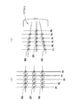
複数の光トラップを連続して生成することによるプローブ500〜502のアレイの動作が、図5に示される。図5(a)に示される実施形態では、第1の所定位置を表わすラインP1に沿って形成されるプローブのアレイの単純な直線運動が示される。動作は、光トラップの第1の所定位置から第2、第3および第4の位置までプローブを転送することにより遂行される。図4をさらに参照して、第1の光トラップの第1の群は、位相パタニング光学部材40の第1領域42にレーザ光線を配向することによって生成される。第1の領域42から放射されたビームレットが集束レンズを通過する時、ビームレットは、プローブ500〜503を含む第1の位置P1で第1の光トラップ群を形成する。
【0060】
第1の位置P1から第2の位置P2にプローブ500〜502を移動させるために、第2の所定位置P2に対応する第2の光トラップ群を生成する第2領域43とレーザ光線とを整列させるために、静的な位相パタニング光学部材40がスピンドル47のまわりで回転する。第1の位置P1の十分近傍に第2の光トラップ群を構築することによって、プローブは、第1の光トラップ群から第2の光トラップ群まで移動される事が出来る。所望の位置P1〜P5に対応して適切な領域42〜46を整列させるべく位相パタニング光学部材を回転させる事によって、シーケンスはプローブを、第2の所定位置P2から第3の所定位置P3まで、第3の所定位置P3から第4の所定位置P4まで、そして第4の所定位置P4から第5の所定位置P5まで連続的に移動させて良い。一組の光学トラップの終了時刻と次の組の光学トラップの開始時刻の時間間隔は、プローブが、ドリフトして脱落する事無く次の組の光学トラップに移動し得る事を保証する時間間隔であるべきである。
【0061】
プローブのこのような動作は、培地内をプローブが転がる機会を増加させるのに有用であり、これによって、培地内のターゲットをプローブと相互作用させる機会が増える。この種の単純な運動は、さらに、サブセル16(図1)から被験セル10内の別の領域に移動させたり、あるいはサブセル16からプローブを分離したりすることにおいて有用であり得る。
【0062】
図5(b)に示された実施形態において、広い間隔から狭い間隔へのプローブの千鳥足状の動作を示す。プローブの千鳥足状の動作は、図5(a)に関して記述されるのと同様の方法によって生じる。しかしながら、第1の領域42は、ラインP1に沿って形成された2つのプローブ500および502と、2つのプローブの中間ではあるがラインP1からは離間しているP2に位置する第3のプローブ501を備える、千鳥足状の光トラップ群を生成する。プローブが千鳥足状に配置されていることによって、プローブが第1の光トラップ群から第2の光トラップ群まで動き出し、第2のおよび後続の位置まで移動するにつれて、プローブが稠密に充填され得る一方で、トラップ群が2つのプローブへ同時に接近しすぎる事が回避され、プローブが誤った光トラップに包含される事を防止する。
【0063】
一旦ターゲットがプローブと相互に作用したならば、ターゲットを調査するためにスペクトル法を使用し得る。陽性の結果(即ち、プローブがターゲットと反応するか結合する)を有するプローブのスペクトルは、非弾性分光法あるいは偏光後方散乱のいずれかに好適な画像化光源39の使用により得ることができる。コンピュータ38は、所望のターゲットを識別し、かつそれらの所望のターゲットを分離するように位相パタニング光学部材に命令するべく、スペクトルのデータを解析することが出来る。スペクトルデータに基づいてターゲットを分離するために用いられる方法が、本発明の範囲から逸脱する事無く、ターゲット、および(または)光データ・ストリームから得られた他の情報に基づいてターゲットを識別および(または)分離するために用いられるように変更され得る事が、当業者にとって認識されるであろう。
【0064】
分析が終了した後、どのプローブを廃棄し、どのプローブを収集するかについての選択が、コンピュータ38および(または)オペレータ36によってなされる。アレイは再配列可能なので、所定の光トラップおよびそれに包含されるプローブが選択的に動く事が出来る。ある場合において、培地3000および非結合ターゲットは、出口18を経由して被験セル10から取り除かれるか洗い流され、分析が終了する。他の場合において、少なくとも光トラップにまだ包含されているプローブのうちのいくつかは、さらに分析を行なうために追加のターゲットとともに再使用される。この技術は、分析のパラメータに依存して、陽性または陰性と試験されたプローブの場合には有用になり得る。更に別の場合、プローブのアレイは、アレイを形成するプローブの量および特性に応じて再配列可能なので、光トラップは、非結合のプローブを廃棄し、かつ更なる実験のための追加のプローブを得るために使用することが出来る。
【0065】
いくつかの実施形態においては、静的にビームを変化させる光学部材40の各領域からビームレットを生成したり、静的にビームを変化させる光学部材40を所定の位置に移動させたりする必要は無い。その代わりに、領域の順序の変更によって、光トラップ群の場所が変更されるであろう。
【0066】
光トラップ50の形成のためのコンパクトなシステムの立面図が、図6(a)に示される。位相パタニング光学部材51は、日本の浜松ホトニクス社によって製造された「PAL−SLMシリーズのX7665」、または、コロラド州ラファイエットのボールダー・ノンリニア・システムズ社によって製造された「SLM512SA7」および「SLM 512SA15」のような、反射的かつ動的な表面を備えた平行配向空間光変調器である動的な光学部材である。
【0067】
図6(a)は光トラップの形成のためのコンパクトなシステムを示す。光学部材51は、ハウジング52と整列するか接続され、そこを貫通して第1光チャネル53aが提供される。第1光チャネルの一端53bは光学部材51のすぐ近傍にあり、第1光チャネルの他端53cが、直交する第2光チャネル53dと交差し連絡している。第2光チャネルは、顕微鏡レンズを取り付けるターレット、即ち「レボルバー」54bのベース54a内に形成される。レボルバー54bは、ニコン社製のTE200型顕微鏡(図示されない)に装着されるようになされる。第2光チャネルは、第2の光チャネルと直交する第3光チャネル55aと更に連絡している。第3光チャネル55aは、レボルバー54bの上面からレボルバーのベース54aまで横断し、また対物レンズ集束レンズ56と平行である。集束レンズはバック・アパーチャ57を形成する形成する頂部および底部を備える。ダイクロイックミラー・ビームスプリッタ58が、第2光チャネルと集束レンズのバック・アパーチャ57の間で、第3の光チャネル内に置かれる。光トラップ50を形成するためのコンパクトなシステム内の他の構成要素は、位相パタニング光学部材から第1光チャネルまで放射するビームレットを反射する第1ミラーM1と、第1ミラーM1によって反射されたビームレットを受けるために整列され、第1光チャネル内に配置された第1伝送光学系TO1と、第1伝送レンズTO1を通り抜けるビームレットを受けるために整列され、第1光チャネル内に配置された第2伝送光学系TO2と、第2転送光学系TO2および第3光チャネル55aを通り抜けるビームレットを反射するために整列され、第1光チャネルおよび第2光チャネルの交点に位置する第2ミラーM2とを備える。
【0068】
光トラップを生成するために、レーザ光線(図示されない)がコリメーター端151の外部の光学系150を通して配向され、光学部材51の動的な表面59によって反射される。光ファイバ150のコリメーター端151を励起する光線(図示されない)は、光学部材51の動的な表面59によって、複数のビームレット(図示されない)へと回折される。各ビームレットの数、種類、および方向は、動的な表面59のメディア中でコード化されたホログラムの変更により制御・変更可能である。その後、ビームレットは、第1ミラーM1で反射され、第1伝送光学系TO1を通って第1光チャネル53aを下り、第2伝送光学系TO2を通って第2ミラーM2へ到達し、ダイクロイックミラー58によって対物レンズ56のバック・アパーチャ57まで配向され、対物レンズ56によって集束され、そこで光トラップを形成するのに必要な光勾配が生成される。ダイクロイックミラー58を貫通して分離する、画像化のための光の一部が第3光チャネル55bのより低い部分を貫通し、光データ・ストリーム(図示されない)を形成する。
【0069】
ビームレットの位相プロファイルが辺縁部においてはそれほど強くなく、辺縁部から内部領域へ向かうにつれてより強くなるという実施形態において、バック・アパーチャ57の約15パーセント未満の過充填は、過充填の無いバック・アパーチャ57によって形成された光トラップと比較して、光トラップの辺縁部においてより大きな強度で光トラップを形成するのに有用である。
【0070】
光トラップ50を形成するためのコンパクトなシステムがマウントされたニコン社製TE200型顕微鏡60の立面図が図6(b)に示される。ハウジング52に取り付けられたレボルバー54が、レボルバー54aおよび54bのためのマウント(図示されない)によって顕微鏡に直接取り付けられる。ハウジングおよびその中身および取り付けられた光学部材51がレボルバー54aおよび54bに固定され、顕微鏡の残りの部分には変更がほとんど必要でないか、全く必要でない。画像化のために、光源61が対物レンズ56の上部に提供されて良い。
【0071】
第1伝送光学系TO1および第2伝送光学系TO2は、それぞれが2つのレンズ部材を含んで図示されている。レンズは凸レンズまたは凹レンズのいずれかであって良い。第1ミラーM1から第2ミラーM2までのイメージ転送を達成するために、空気によって離間された対称な一重線、空気によって離間された対称な二重線、および(または)追加のレンズまたはレンズ群のような、別々の異なる種類や数のレンズが選択され得る。いくつかの実施形態において、第1および第2伝送光学系は空気によって離間された二重線であり、望遠レンズとしても機能させるために少し離間している。
【0072】
本願明細書に関する本発明の範囲内において、特定の修正が上記のシステム装置および方法に対してなされ得るので、添付の図面および明細書に示すように、上記の記載に含まれる全ての事項が例証として解釈される事を意図しており、制限する事を意図していない。
【図面の簡単な説明】
【0073】
【図1】配列可能なプローブのアレイを形成するシステムの一部を切り欠いた側面図である。
【図2】光トラップ内に包含される自由プローブを示す図である。
【図3】プローブのアレイの形成のためのシステムの概観を示す。
【図4】複数の静的な領域を備えるビーム変化部材を示す。
【図5】(a)は、プローブの第1の動作を示し、(b)は、プローブの第2の動作を示す。
【図6a】(a)は、光トラップを形成するためのコンパクトなシステムの構成図である。
【図6b】(b)は、図6(a)のコンパクトなシステムが接続される倒立顕微鏡を示す。
【符号の説明】
【0074】
8...配列可能なアレイ、
10...被験セル(容器)、
12...集束レンズ、
14...入口
16...サブセル
18...出口
22...位相パタニング光学部材、
28...バック・アパーチャ、
100...レーザビーム、
102...レーザ、
500〜504...基質結合プローブ、
2000〜2004...ビームレット、
1000〜1004...光トラップ、【Technical field】
[0001]
Throughout this application, various references are referenced. The entire disclosures of these documents are incorporated herein by reference in the present application to describe the state of the art relating to the present invention.
[0002]
The present invention relates broadly to arrays of probes. More particularly, the present invention relates to systems and methods that use multiple light traps to form an array of arrayable and dynamic probes, with or without substrate binding.
[Background Art]
[0003]
Until now, arrays of potentially reactive probes have been used in analysis and other chemical and biological tests and experiments. For example, arrays are often used in the fields of genetics, biochemistry and biology to analyze samples (targets) of biological or chemical substances. In many cases, analytical samples are only available in relatively small quantities. Due to the small amount of material available, microarrays have been developed that are useful for providing a relatively high density of probes in a small array for analyzing targets in small samples.
[0004]
Microarrays used in the analysis of biological materials are often referred to as biochips. Two main applications of biochips are extraction of sequence information on specific nucleic acids (whole genome of an organism, a single gene or a part of a single gene) (Patent Document 1), and evaluation of expression (Non-Patent Document 1, Non-Patent Document 2, and Non-Patent Document 3).
[0005]
Conventional microarrays are attached to the surface of a planar solid support (substrate) and consist of oligonucleotide probes having either a one-dimensional or two-dimensional configuration. Different types of oligonucleotides attach to the substrate at predetermined locations. Thus, once the microarray is formed, the location of the probes, and thus all targets that respond to the probes, is always known. Attachment of the probe is achieved either by direct synthesis of the oligonucleotide onto the substrate by a process known as in situ photolithography synthesis (US Pat. You.
[0006]
One disadvantage of such microarrays is that the one-dimensional or two-dimensional configuration limits the surface area on which the probes can be mounted and sets a limit on the density of probes for analyzing a target. In the case of DNA hybridization between a target (DNA or DNA fragment) and a probe (immobilized oligonucleotide), the rate of hybridization is controlled by the rate at which the target can contact the probe. Thus, the higher the probe density, the higher the rate of hybridization.
[0007]
A second disadvantage of such microarrays arises from their fabrication method. Once the microarray is fabricated, the type and amount of probe will be determined.
[0008]
Another approach for analyzing targets in small samples is to attach the probe to the surface of a small bead-like substrate (US Pat. Each bead with a different probe is identified by an individual label, which allows the identification of each probe and bound target by identifying which beads have which label after analysis (see US Pat. reference).
[0009]
The identity of the bead and the probe is maintained by physically moving the bead with the probe attached to the guide, capillary, groove or hole in the sheet and subsequently cleaning the bead with the target. The non-flat nature of the beads provides a larger area for the target to respond when compared to microarray probes, while determining the identity of which beads supported which probes to determine identity. Beads must be kept in a predetermined order during analysis to keep records, or bead probes must be retrieved and each bead probe inspected after analysis
[0010]
A further disadvantage of both microarray and bead analysis is that the probe must be in physical contact with the substrate. In some instances, this contact alters the probe inside and itself, or affects the process in which the probe is used during analysis. In other instances, during or after the initial analysis, a desired change in the quantity or quality of the probe if the identity of the probe is known throughout the analysis and the sequence composition can be easily changed. May have gained useful information. However, such changes are not possible in microarray or bead analysis.
[0011]
In an unrelated technique, a technique for optically trapping particles with a plurality of simultaneously generated optical tweezers is known (see generally US Pat. Optical tweezers use gradient forces on light rays to trap particles based on the dielectric constant of the particles. In order to minimize energy, where the electric field is highest, particles having a higher dielectric constant than the surrounding media migrate to the area of the optical tweezers.
[0012]
Other types of traps that can be used to optically trap particles include, but are not limited to, optical vortex, optical bottle, optical rotator, and optical cage. Optical vortexing is a gradient surrounding a region of zero electric field that is useful for manipulating particles with a lower dielectric constant than the surrounding media, or reflective particles, or other types of particles that are repelled by optical tweezers. Generate In order to minimize energy, such particles will move to the region where the electric field is lowest, ie, the zero electric field region at the focus of a properly formed laser beam. Optical vortexing provides a region of zero electric field, such as a donut hole (toroid). The light gradient is distributed radially and has the highest electric field around the circumference of the donut. An optical vortex detains small particles in the hole of the donut. Detention is accomplished by sliding the vortex on small particles along the zero electric field equipotential lines.
[0013]
A light bottle differs from a light vortex in that it has a zero electric field only at the focal point, and at the end of the vortex a non-zero electric field surrounds the focal point in all other directions. Light bottles can be useful in trapping atoms and nanoclusters that are too small or too absorptive to be trapped with light vortices or tweezers [4].
[0014]
An optical rotator is a recently described optical tool that provides a pattern of spiral arms that trap an object [5]. This class of tools can be useful for manipulating non-spherical particles or manipulating MEM devices or nanomachines.
[0015]
The optical cage (Neil, Patent Document 7) is an enlarged version of the same optical vortex. The optical cage forms a time-averaged ring of optical tweezers to enclose particles that are too large or reflective to trap with a lower dielectric constant than the surrounding media. However, unlike the vortex, no zero electric field region is formed. Optical vortices are similar in their use to optical tweezers, but operate on the opposite principle.
[0016]
[Patent Document 1]
U.S. Pat. No. 6,025,136
[Patent Document 2]
U.S. Pat. No. 5,838,732
[Patent Document 3]
U.S. Pat. No. 5,143,854
[Patent Document 4]
WO 00/61198 pamphlet
[Patent Document 5]
International Publication No. 00/71243 pamphlet
[Patent Document 6]
US Patent No. 6055106
[Patent Document 7]
U.S. Pat. No. 5,939,716
[Non-patent document 1]
Senna M et al., "Quantitative monitoring of expression patterns with complementary DNA microarrays" (Science 270 (5235): 467-70; (Oct. 20, 1995))
[Non-patent document 2]
D. J. And Winseller E. A. "Genomics, expression and DNA arrays" (Nature 405 (6788): 827-836 (2000)).
[Non-Patent Document 3]
Ekins R. And Shu F. W. "Microarray: its origins and applications" (Trend in Biotechnology, 17: 217-18 (1999))
[Non-patent document 4]
J. Aalto and M.A. J. Paget "Generating a Beam with a Dark Focus Surrounded by Higher Intensity Regions: Light Bottle Beam" (Optical Letters, 25, 191-193, 2000)
[Non-Patent Document 5]
L. Peterson, M. P. McDonald, J.M. Aalto, W. Civet, p. E. FIG. Bryant and K.S. Drakia, "Suppressed Rotation of Optically Trapped Microscopic Particles" (Science 292, 912-914, 2001)
DISCLOSURE OF THE INVENTION
[Problems to be solved by the invention]
[0017]
There is a need for analytical methods and systems that can evaluate the interaction of a probe with a target without contacting the probe with a substrate. There is a further need for methods and systems for forming arrays of reproducible and reproducible probes, and methods for maintaining probe identity throughout an analysis, regardless of probe location. The present invention satisfies these and other needs, and provides further related advantages.
[Means for Solving the Problems]
[0018]
The present invention provides new and improved methods and systems for constructing, arranging, and using a three-dimensional array of probes.
[0019]
An optical trap is created in the container. Optical traps are created by distributing a beam, such as a laser beam, on an optical element that changes the beam by patterning its phase to create a beamlet. Subsequently, the beamlets are focused by the lens to create the necessary gradient conditions for the light trap. Subsequently, a probe of known properties is added to the container. Predetermined analytical probes are selected, each of which is then selected for inclusion in an optical trap.
[0020]
The quantity and quality of the probes forming the array can be easily rearranged by using optical traps to add, discard, or replace probes. The arrangement of the probes in the array with each other is dynamic because the spatial relationship between the probes can be varied while maintaining the identity of the probes selected to construct the array. Thus, both the array and each probe can move in three dimensions, and the probes can be positioned, moved, and repositioned in the container, either entirely or separately.
[0021]
When a probe is contained within an optical trap, it is included regardless of whether it has been repositioned in the container and regardless of the `` order '' of spatial locations in the array. The identity of the probe can be maintained by knowing the identity of the optical trap being used. Further, one optical trap can pass a probe to another optical trap, tracking the chain of restraints of the probe by the optical trap, thereby determining which probe is encompassed by the optical trap. Can be maintained.
[0022]
Other features and advantages of the invention will be set forth in part in the detailed description that follows, and in the accompanying drawings, and preferred embodiments of the invention will be considered in consideration of the detailed description that is set forth below in conjunction with the accompanying drawings. And some of which will be apparent to those skilled in the art, or may be made apparent by practice of the invention. The advantages of the invention may be realized and attained by means of the instruments and combinations particularly pointed out in the appended claims.
BEST MODE FOR CARRYING OUT THE INVENTION
[0023]
Specific embodiments of the present invention are described in considerable detail below to illustrate its principles and operation. However, various modifications can be made, and the scope of the present invention is not limited to the specific embodiments described later. For example, while biological systems and assays are specifically mentioned for gene sequencing and DNA hybridization, the methods and systems may be used to fabricate and test optical circuits, fabricate nanocomposites, and fabricate optoelectronics. Used in fields such as testing of electronic components, assembly and testing of holographic data storage matrices, drug analysis, genomic analysis, proteomics analysis, facilitation of combinatorial chemistry, promotion of colloid self-assembly, investigation of non-biological materials, etc. Will be recognized.
[0024]
Certain terms are used herein for convenience and reference, but are not limited to the meaning below. A brief definition is provided below.
[0025]
A. A "beamlet" is a sub-beam of light generated by passing a light beam, such as a collimated output from a laser or light-emitting diode, or other energy source, through a medium that diffracts it into two or more sub-beams. Or mention other energy sources. An example of a beamlet would be a higher order laser beam diffracted by a grating.
[0026]
B, "Phase profile" refers to the phase of light or other energy source in the cross section of a beam or beamlet.
[0027]
C, "Phase patterning" refers to a beam of light or a phase profile changing light, including diffraction, phase modulation, mode shaping, splitting, focusing, splitting, forming, or other methods of manipulating the beam or beamlet. It refers to the patterned phase shift imparted to the beamlets. The method of manipulating the beam or beamlet is not limited to the above.
[0028]
D, "Probe" refers to a biological material or other chemical that selectively binds or reacts with a target. Probes include oligonucleotides, polynucleotides, compounds, proteins, peptides, lipids, polysaccharides, ligands, cells, antibodies, antigens, cell organelles, lipids, blastomeres, cell aggregates, microorganisms, complementary DNA, RNA Etc., but is not limited thereto.
[0029]
E. FIG. "Target" refers to a biological or other chemical substance whose presence or absence in a sample is detected by binding or reacting the target with a probe. For example, the presence of a target formed from the genetic material is indicative of a reaction such as a hybridization reaction between the target genetic material and a probe genetic material having specific properties, ie, having a complementary structure required for hybridization. Is detected by Target materials are also oligonucleotides, polynucleotides, compounds, proteins, lipids, polysaccharides, ligands, cells, antibodies, antigens, organelles of cells, lipids, blastomeres, aggregates of cells, microorganisms, complementary DNA, RNA Etc., but is not limited thereto.
【Example】
[0030]
As shown in FIG. 1, probes 500-504 may bind or react with any suitable substrate by any suitable binding process or protocol. An important feature of a suitable substrate is that it is a material that is contained in and scanned by the light trap. Representative dielectric substrates include beads, irregular small particles, or other regular small particles. Suitable substrates include CPG, ceramics, silica, titanium dioxide, latex, polystyrene, methyl styrene, polymethyl methacrylate, paramagnetic materials, trisol, cross-linked dextrans such as graphite, teflon, sepharose, cellulose, nylon Manufactured from plastic-containing materials such as, but not limited to, cross-linked micelles, liposomes and membrane vesicles.
[0031]
As shown in another embodiment illustrated in FIG. 2, the method of the present invention comprises providing one or more probes 505 (one of which is shown) not bound to a substrate. And one or more optical traps 1005, one of which is shown. It is to be understood that an arrayable array can include only bound probes, only unbound probes, or a combination of bound and unbound probes. When bound and unbound probes are combined, the choice of what combination of bound and unbound probes to take may be influenced in part by the physical properties of the probe. In particular, the properties of certain probes, such as skin cells, can change without contacting the substrate. Conversely, by removing the substrate and maintaining the tertiary structure of the probe / protein, the action of other probes, such as proteins, can be better contributed.
[0032]
FIG. 1 shows an
[0033]
FIG. 3 shows an overview of a
[0034]
Any suitable laser can be used as the source of the
[0035]
[0036]
When the
[0037]
In embodiments where the phase profile of the beamlets is not as strong at the edges and becomes stronger from the edges toward the interior region, less than about 15 percent overfilling of the
[0038]
Suitable phase patterning optics are characterized as being transmissive or reflective depending on how the focused light beam or other energy source is oriented. Transmissive diffractive optics transmit light or other sources of energy, while reflective diffractive optics reflect beams.
[0039]
Phase patterning optics can also be categorized as having a static or dynamic surface. Examples of suitable static phase patterning optics include diffraction gratings, gratings including reflective and transmissive gratings, holograms including polychromatic holograms, stencils, holographic filters for shaping light, polychromatic holograms, lenses , Mirrors, prisms, waveplates, and the like, including those with one or more fixed surface areas. The static transmissive
[0040]
Examples of suitable dynamic phase-patterning optics that exhibit a time-dependent aspect to their function include computer-generated diffraction patterns, phase-shifting materials, and liquid crystal phase-shifting, including piston-mode micromirror arrays. Includes arrays, spatial light modulators, electro-optic deflectors, acousto-optic modulators, deformable mirrors, reflective MEMS arrays and the like. In dynamic phase-patterning optics, the media containing the phase-patterning optics encodes a hologram, and the hologram can be changed to provide a patterned phase shift to the focused light beam, such as a diffraction or focusing. Resulting in a corresponding change in the phase profile of the light beam. Further, the media can be changed to change the position of the optical trap. This is an advantage of dynamic phase patterning optics, where the media can be changed to move each of the optical traps separately.
[0041]
Suitable dynamic optics are "PAL-SLM Series X7665" manufactured by Hamamatsu Photonics, Japan, or "SLM512N15" and "SLM512SA7" manufactured by Boulder Nonlinear Systems, Lafayette, CO. ”. These phase patterning optics generate beamlets and are controlled to produce beamlets 2000-2004 (FIG. 1) by coded holograms in media that can be changed to select the beamlet format. Computer.
[0042]
In some embodiments, the type of optical trap to form the array and / or the position of the optical trap is changed to allow for alignment and rearrangement. This format can be changed from its original format to the format of optical tweezers, optical vortex, optical bottle, optical rotator or optical cage.
[0043]
In addition, phase patterning optics are useful for imparting a particular phase geometry mode to laser light, for example, by converting from a Gaussian mode to a Gauss-Laguerre mode. Thus, some beamlets may be generated in Gaussian-Laguerre mode and other beamlets may be generated in Gaussian mode.
[0044]
The probe is formed in the
[0045]
Probes having the particular properties required to bind and / or react with the desired target are selected for addition into a container and inclusion in an arrayable array. In some of the embodiments, where the probe is bound to a substrate, the substrate is labeled with a tracer, such as a wavelength-specific dye, to facilitate probe selection. In a preferred embodiment, all substrate binding probes having the same binding or reaction properties are labeled with the same type of tracer. If the substrate is labeled with a wavelength-specific tracer, selection of probes 500-504 can be accomplished by adding a probe bound to the labeled substrate to
[0046]
In embodiments where unlabeled probes are selected to form all or part of an array, the probes can be added to the
[0047]
As seen in FIG. 3, spectroscopy of a sample of biological material can be performed with an
[0048]
In other embodiments, labeled probes or unlabeled probes, such as unlabeled probes having different binding or reaction properties, are placed in a row of
[0049]
The placement of the probes in the
[0050]
The optical traps 1000-1004 are then used to trap the selected probes 500-504 by including the probes in the optical traps 1000-1004. Such included probes are formed to form an array.
[0051]
The method and system of the present invention are suitable for semi-automated or automated processes for tracking the operation of each optical trap and its contents. This operation can be monitored by video cameras, spectral or optical data streams, which control the selection of probes and the type of probes included in the optical trap and the composition of the probes forming the array. Computer control of the generation of useful optical trap information. In another embodiment, this operation is tracked based on a predetermined operation of each optical trap caused by the encoding of the phase patterning optics. Further, in some embodiments, a computer is used to maintain a record of each probe included in each light trap.
[0052]
Referring again to the
[0053]
The optical data stream is then viewed, converted to a video signal, monitored, or analyzed by a
[0054]
To build the array, an
[0055]
Further, the position of one or more probes trapped in the array can be tracked by monitoring the position of the optical trap containing the probe. Then, using such information, any probes in the array may be separately repositioned in the test cell by altering the surface of the phase patterning optics, and the identity of each probe is Regardless of where the trap locates the probe, it is stored by the optical trap in which the probe is contained.
[0056]
In a preferred embodiment,
[0057]
Referring to FIGS. 1 and 3, a batch of first targets T1-T5 is added through inlet 14 to a
[0058]
For example, in one embodiment, probes 500-504 are rolled in medium 3000 containing targets T1-T5. By including the probe optically rather than physically, moving the probe within the
[0059]
The operation of an array of probes 500-502 by sequentially generating multiple optical traps is shown in FIG. In the embodiment shown in FIG. 5 (a), a simple linear movement of an array of probes formed along a line P1 representing a first predetermined position is shown. The operation is performed by transferring the probe from a first predetermined position of the optical trap to a second, third and fourth position. Still referring to FIG. 4, a first group of first light traps is created by directing a laser beam to a first region 42 of the
[0060]
In order to move the
[0061]
Such operation of the probe is useful to increase the chance of the probe rolling in the medium, thereby increasing the chance of the target in the medium interacting with the probe. This kind of simple movement may also be useful in moving the subcell 16 (FIG. 1) to another area within the
[0062]
FIG. 5B shows a staggered movement of the probe from a wide interval to a narrow interval in the embodiment shown in FIG. The staggered movement of the probe occurs in a manner similar to that described with respect to FIG. However, the first area 42 includes two
[0063]
Once the target has interacted with the probe, spectral methods can be used to probe the target. The spectrum of the probe with a positive result (ie, the probe reacts with or binds to the target) can be obtained by using an
[0064]
After the analysis is completed, a selection is made by
[0065]
In some embodiments, it is not necessary to generate a beamlet from each region of the static beam changing
[0066]
An elevation view of a compact system for forming the
[0067]
FIG. 6 (a) shows a compact system for forming an optical trap. The
[0068]
A laser beam (not shown) is directed through
[0069]
In embodiments where the phase profile of the beamlets is not as strong at the edges and becomes stronger from the edges toward the interior region, overfilling of the
[0070]
An elevation view of a
[0071]
The first transmission optical system TO1 and the second transmission optical system TO2 are each shown including two lens members. The lens can be either a convex lens or a concave lens. To achieve image transfer from the first mirror M1 to the second mirror M2, a symmetric singlet separated by air, a symmetric doublet separated by air, and / or an additional lens or lens group Different different types and numbers of lenses can be selected. In some embodiments, the first and second transmission optics are double lines separated by air and are slightly separated to also function as a telephoto lens.
[0072]
Since certain modifications can be made to the above system devices and methods within the scope of the present invention in connection with the present specification, all matter contained in the above description is illustrated as illustrated in the accompanying drawings and specification. It is intended to be interpreted as non-limiting.
[Brief description of the drawings]
[0073]
FIG. 1 is a cutaway side view of a system for forming an array of probes that can be arranged.
FIG. 2 shows a free probe contained within an optical trap.
FIG. 3 shows an overview of a system for forming an array of probes.
FIG. 4 shows a beam changing member with a plurality of static regions.
5A illustrates a first operation of the probe, and FIG. 5B illustrates a second operation of the probe.
FIG. 6 (a) is a block diagram of a compact system for forming an optical trap.
6 (b) shows an inverted microscope to which the compact system of FIG. 6 (a) is connected.
[Explanation of symbols]
[0074]
8 ... arrayable array,
10 ... test cell (container),
12 ... Focusing lens,
14. Entrance
16 ... Subcell
18 ... Exit
22 ... phase patterning optical member,
28 ... back aperture,
100 ... laser beam,
102 ... Laser,
500-504 ... substrate binding probe,
2000-2004 ... beamlet,
1000 to 1004 ... light trap,
Claims (157)
容器内に少なくとも2つの移動可能な光トラップを生成し、
前記容器内に少なくとも2つのプローブを設け、
前記光トラップ内に包含されるプローブアレイへ含有するものとして、少なくとも2つのプローブを選択し、
該選択された各プローブを前記光トラップの1つにトラッピングして、前記光トラップ内に包含されるプローブアレイを配列し、
該トラップされた前記プローブを包含する前記光トラップの位置をモニターすることで、少なくとも1つのトラップされたプローブの位置を追跡することを特徴とする方法。A method of arranging and tracking probes, comprising:
Creating at least two movable light traps in the container;
Providing at least two probes in the container,
Selecting at least two probes for inclusion in the probe array contained in the optical trap;
Trapping each of said selected probes into one of said optical traps to arrange a probe array contained within said optical trap;
Tracking the position of at least one trapped probe by monitoring the position of the optical trap containing the trapped probe.
容器内に少なくとも2つの移動可能な光トラップを生成し、
前記容器内に流体培地を設け、
前記流体培地内に少なくとも2つの生体物質用プローブを設け、
アレイへ含有するものとして、少なくとも2つのプローブを選択し、
該選択された各プローブを前記光トラップの1つにトラッピングし、
前記生体物質を含む少なくとも1つのターゲットを前記容器内へ導入し、
トラップされたプローブのそれぞれと各ターゲットとの反応の有無を判定することを含むことを特徴とする方法。A method for analyzing biological material, comprising:
Creating at least two movable light traps in the container;
Providing a fluid medium in the container,
Providing at least two biological substance probes in the fluid medium,
Selecting at least two probes for inclusion in the array;
Trapping each of said selected probes into one of said optical traps;
Introducing at least one target containing the biological material into the container,
Determining whether there is a reaction between each of the trapped probes and each of the targets.
容器内に少なくとも二つの可動な光トラップを生成し、
前記容器内に少なくとも二つの前記プローブを供給し、及び
前記光トラップの一つで各プローブを選択することにより前記少なくとも二つのプローブ・アレイを配列することを特徴とする方法。A method of arranging probe arrays, comprising:
Creating at least two movable light traps in the container,
Providing at least two of said probes in said container and arranging said at least two probe arrays by selecting each probe with one of said optical traps.
位相パタニング光学部材から放射される複数のビームレットを形成するために、前記位相パタニング光学部材に光の集束ビームを指向させ、
容器内に可動の光トラップを生成するために、集束レンズを介して前記複数のビームレットを通過させ、且つ、記集束レンズから放出される前記複数のビームレットを収束させるためにバック・アパーチャに前記複数のビームレットを指向させ、
前記容器内に複数のプローブを供給し、
前記光トラップ内に包含されたプローブ・アレイでの介在物のための少なくとも二つのプローブを選択し、
前記光トラップ内に含有されたプローブ・アレイを配列するために前記光トラップの一つで前記選択されたプローブをそれぞれトラップし、及び
前記光トラップ内に含有されたプローブ・アレイを再配列するために、前記プローブを含有している前記光学トラップを移動させることにより、前記光トラップ内に含有されている前記プローブの少なくとも一つの位置を変えることを特徴とする方法。A method of arranging probe arrays, comprising:
Directing a focused beam of light to the phase patterning optical member to form a plurality of beamlets radiated from the phase patterning optical member;
Passing the plurality of beamlets through a focusing lens to create a movable optical trap in the container, and a back aperture to converge the plurality of beamlets emitted from the focusing lens. Directing the plurality of beamlets,
Supplying a plurality of probes in the container,
Selecting at least two probes for inclusions in the probe array contained within the optical trap;
Trapping each of the selected probes with one of the optical traps to arrange a probe array contained within the optical trap, and rearranging the probe array contained within the optical trap; Moving the optical trap containing the probe to change the position of at least one of the probes contained in the optical trap.
光の集束ビームを生成するための光源と、
略透明な容器と、
前記容器の内容物を照射する光のビームを生成するための画像化光源と、
指向用のビームスプリッタと、
前記光源から発せられる光の集束ビームを受信し且つ少なくとも二つのビームレットに回折し、集束レンズのバック・アパーチャに前記ビームレットそれぞれを指向させるための表面を有する位相パタニング光学部材であり、前記表面は前記ビームレットの少なくとも一つの位相形状且つ/または配向を変化するように変化され、プローブを包含するための光トラップを形成するために、前記集束レンズはそれぞれの前記ビームレットを収束させること特徴とする、位相パタニング光学部材と、
前記容器の内容物を照射する光のビームを受信し且つ少なくとも一つの光トラップの動作及び内容物を追跡するためのモニタと、を有するシステム。A system for forming and tracking an optical trap containing a probe, the system comprising:
A light source for producing a focused beam of light;
A substantially transparent container,
An imaging light source for generating a beam of light illuminating the contents of the container;
A beam splitter for pointing,
A phase patterning optical member having a surface for receiving a focused beam of light emitted from the light source and diffracting the beamlet into at least two beamlets and directing each of the beamlets to a back aperture of a focusing lens; Is varied to change at least one phase shape and / or orientation of the beamlets, and wherein the focusing lens focuses each of the beamlets to form an optical trap for containing a probe. A phase patterning optical member,
A monitor for receiving a beam of light illuminating the contents of the container and tracking operation and contents of at least one light trap.
前記ターゲットに結合された複数のプローブと、
光の集束ビームを生成するための光源と、
略透明な容器と、
前記容器の内容物を照射する光のビームを生成するための画像化光源と、
前記光源から発せられる前記集束光のビーム、及び前記容器の内容物を照射する光のビームとを指向させるビームスプリッタと、
前記光源から発せられる光の集束ビームを受信し且つ少なくとも二つのビームレットに回折し、集束レンズのバック・アパーチャに前記ビームレットそれぞれを指向させるための表面を有する位相パタニング光学部材であり、前記表面は前記ビームレットの少なくとも一つの位相形状且つ/または配向を変化するように変化され、前記ターゲットに結合された前記プローブを包含する光トラップを形成するために、前記集束レンズはそれぞれの前記ビームレットを収束させること特徴とする、前記位相パタニング光学部材と、及び
前記容器の内容物を照射する光のビームを受信し且つ少なくとも一つの光トラップの動作及び内容物を追跡するためのモニタと、を有するシステム。A system for forming and tracking an optical trap containing an optical probe coupled to a target, the system comprising:
A plurality of probes bound to the target;
A light source for producing a focused beam of light;
A substantially transparent container,
An imaging light source for generating a beam of light illuminating the contents of the container;
A beam splitter for directing a beam of the focused light emitted from the light source, and a beam of light for irradiating the contents of the container,
A phase patterning optical member having a surface for receiving a focused beam of light emitted from the light source and diffracting the beamlet into at least two beamlets and directing each of the beamlets to a back aperture of a focusing lens; Is varied to change at least one phase shape and / or orientation of the beamlets, and the focusing lens is coupled to each of the beamlets to form an optical trap containing the probe coupled to the target. Wherein the phase patterning optics and a monitor for receiving a beam of light illuminating the contents of the container and tracking the operation and contents of at least one light trap. Having system.
光の集束ビームを生成するための光源と、
上部及び底部を有する集束レンズであって、前記底部はバック・アパーチャを形成することを特徴とする集束レンズと
前記光源から発せられる光の集束ビームを受信し且つ少なくとも二つのビームレットに回折し、集束レンズのバック・アパーチャに前記ビームレットそれぞれを指向させるための表面を有する位相パタニング光学部材と
第一端及び第二端を有する第一光チャンネルであって、前記第一端が前記位相パタニング光学部材と通信することを特徴とする第一光チャンネルと、
第一端及び第二端を有する第二光チャンネルとであって、該第一端が前記第一光チャンネルの第二端に交差することを特徴とする第二光チャンネルと、
第一端及び第二端を有する第三光チャンネルとであって、該第一端が前記第二光チャンネルの第二端と通信する第四光チャンネルと、
前記第一光チャンネルを介して前記位相パタニング光学部材から発せられる前記ビームレットを反射するための第一ミラーと、
前記第一光チャンネル内に配設された搬送オプティクスの第一セットであって、前記第一ミラーにより反射された前記ビームレットを受けるように整列されることを特徴とする搬送オプティクスの第一セットと、
前記第一光チャンネル内に配設された搬送オプティクスの第二セットであって、搬送レンズの第一セットを通過する前記ビームレットを受けるように整列されることを特徴とする搬送オプティクスの第二セットと、
前記第一光チャンネルと前記第二光チャンネルとの交点に位置付けられた第二ミラーであって、前記第三光チャンネルを介して搬送オプティクスの前記第二セットを通過するビームレットを反射するように整列されることを特徴とする第二ミラーと、
前記第三光チャンネルを介して前記集束レンズのバック・アパーチャに通過するビームレットを反射し、且つ光トラップのアレイを形成するために前記第三光チャンネル内に配設された第三ミラーと、を有する装置。An apparatus for forming an array of optical traps, comprising:
A light source for producing a focused beam of light;
A focusing lens having a top and a bottom, wherein the bottom receives a focused beam of light emitted from the light source and a focusing lens, wherein the bottom forms a back aperture, and diffracts into at least two beamlets; A phase patterning optical member having a surface for directing each of the beamlets to a back aperture of a focusing lens, and a first optical channel having a first end and a second end, wherein the first end is the phase patterning optical member. A first optical channel characterized by communicating with the member;
A second optical channel having a first end and a second end, wherein the second end crosses the second end of the first optical channel;
A third optical channel having a first end and a second end, a fourth optical channel having the first end communicating with a second end of the second optical channel;
A first mirror for reflecting the beamlet emitted from the phase patterning optical member via the first optical channel;
A first set of transport optics disposed in the first optical channel, the first set of transport optics being arranged to receive the beamlets reflected by the first mirror. When,
A second set of transport optics disposed in the first optical channel, the second set of transport optics being arranged to receive the beamlets passing through the first set of transport lenses. Set and
A second mirror positioned at the intersection of the first light channel and the second light channel to reflect beamlets passing through the second set of transport optics through the third light channel. A second mirror characterized by being aligned;
A third mirror disposed within the third light channel to reflect a beamlet passing through the third light channel to the back aperture of the focusing lens and to form an array of light traps; An apparatus having
Applications Claiming Priority (2)
| Application Number | Priority Date | Filing Date | Title |
|---|---|---|---|
| US88680201A | 2001-06-20 | 2001-06-20 | |
| PCT/US2002/011586 WO2003001178A2 (en) | 2001-06-20 | 2002-04-12 | Configurable dynamic three dimensional array |
Publications (3)
| Publication Number | Publication Date |
|---|---|
| JP2004532991A true JP2004532991A (en) | 2004-10-28 |
| JP2004532991A5 JP2004532991A5 (en) | 2006-01-05 |
| JP4199107B2 JP4199107B2 (en) | 2008-12-17 |
Family
ID=25389806
Family Applications (1)
| Application Number | Title | Priority Date | Filing Date |
|---|---|---|---|
| JP2003507524A Expired - Fee Related JP4199107B2 (en) | 2001-06-20 | 2002-04-12 | Arrayable dynamic 3D array |
Country Status (6)
| Country | Link |
|---|---|
| EP (1) | EP1412519A4 (en) |
| JP (1) | JP4199107B2 (en) |
| CN (2) | CN1545561A (en) |
| CA (1) | CA2451222A1 (en) |
| NZ (1) | NZ530239A (en) |
| WO (1) | WO2003001178A2 (en) |
Cited By (2)
| Publication number | Priority date | Publication date | Assignee | Title |
|---|---|---|---|---|
| JP2010538645A (en) * | 2007-09-11 | 2010-12-16 | アリックス インク | Combined method and apparatus for sorting objects |
| JP2010538644A (en) * | 2007-09-13 | 2010-12-16 | アリックス インク | Method and apparatus for screening objects in forensic DNA analysis and medical diagnosis |
Families Citing this family (10)
| Publication number | Priority date | Publication date | Assignee | Title |
|---|---|---|---|---|
| DE20306138U1 (en) | 2003-04-16 | 2003-09-04 | Monajembashi, Shamci, Dr., 69126 Heidelberg | Preparation of biological target cells, with auxiliary erythrocytes, has a glass carrier for use with a multi-beam laser as optical tweezers for manipulation to examine the cell elasticity |
| US7449679B2 (en) * | 2003-10-28 | 2008-11-11 | Arryx, Inc. | System and method for manipulating and processing materials using holographic optical trapping |
| US7411181B2 (en) * | 2003-10-28 | 2008-08-12 | Arryx, Inc. | System and method for manipulating and processing materials using holographic optical trapping |
| GB0416498D0 (en) | 2004-07-23 | 2004-08-25 | Council Cent Lab Res Councils | Optically controllable device |
| US8169600B2 (en) | 2006-09-15 | 2012-05-01 | Arryx, Inc. | Surface mapping by optical manipulation of particles in relation to a functionalized surface |
| EP2150806A4 (en) * | 2007-05-10 | 2013-01-02 | Pacific Biosciences California | Methods and systems for analyzing fluorescent materials with reduced autofluorescence |
| US9174752B2 (en) * | 2008-04-23 | 2015-11-03 | Signode Industrial Group Llc | Strapping device with a gear system device |
| CN104520436B (en) * | 2012-06-18 | 2017-07-28 | 索布鲁解决方案公司 | Microorganism evaluation system |
| CN109239937A (en) * | 2018-09-15 | 2019-01-18 | 天津大学 | A kind of optical tweezer automation control device |
| CN113053556A (en) * | 2021-03-10 | 2021-06-29 | 暨南大学 | Biological micromotor array with reconfigurability and application thereof |
Family Cites Families (4)
| Publication number | Priority date | Publication date | Assignee | Title |
|---|---|---|---|---|
| JP3102523B2 (en) * | 1992-10-12 | 2000-10-23 | 日本電信電話株式会社 | Fine particle array control method |
| US5776674A (en) * | 1995-06-05 | 1998-07-07 | Seq, Ltd | Chemical biochemical and biological processing in thin films |
| CN1079158C (en) * | 1996-11-26 | 2002-02-13 | 中国科学院上海光学精密机械研究所 | Optical suspension measuring system |
| US6055106A (en) * | 1998-02-03 | 2000-04-25 | Arch Development Corporation | Apparatus for applying optical gradient forces |
-
2002
- 2002-04-12 CN CNA028162889A patent/CN1545561A/en active Pending
- 2002-04-12 WO PCT/US2002/011586 patent/WO2003001178A2/en not_active Ceased
- 2002-04-12 CA CA002451222A patent/CA2451222A1/en not_active Abandoned
- 2002-04-12 NZ NZ530239A patent/NZ530239A/en not_active Application Discontinuation
- 2002-04-12 EP EP02731351A patent/EP1412519A4/en not_active Withdrawn
- 2002-04-12 CN CN 200510081431 patent/CN1715918B/en not_active Expired - Fee Related
- 2002-04-12 JP JP2003507524A patent/JP4199107B2/en not_active Expired - Fee Related
Cited By (2)
| Publication number | Priority date | Publication date | Assignee | Title |
|---|---|---|---|---|
| JP2010538645A (en) * | 2007-09-11 | 2010-12-16 | アリックス インク | Combined method and apparatus for sorting objects |
| JP2010538644A (en) * | 2007-09-13 | 2010-12-16 | アリックス インク | Method and apparatus for screening objects in forensic DNA analysis and medical diagnosis |
Also Published As
| Publication number | Publication date |
|---|---|
| CN1715918A (en) | 2006-01-04 |
| HK1078933A1 (en) | 2006-03-24 |
| EP1412519A2 (en) | 2004-04-28 |
| CN1715918B (en) | 2010-05-12 |
| EP1412519A4 (en) | 2007-07-04 |
| WO2003001178A3 (en) | 2003-02-27 |
| CA2451222A1 (en) | 2003-01-03 |
| NZ530239A (en) | 2006-08-31 |
| CN1545561A (en) | 2004-11-10 |
| WO2003001178A2 (en) | 2003-01-03 |
| JP4199107B2 (en) | 2008-12-17 |
Similar Documents
| Publication | Publication Date | Title |
|---|---|---|
| US7659983B2 (en) | Hybrid random bead/chip based microarray | |
| US9297762B2 (en) | Spatial positioning of spectrally labeled beads | |
| US7586684B2 (en) | Solute characterization by optoelectronkinetic potentiometry in an inclined array of optical traps | |
| AU771238B2 (en) | Method and device for producing and/or analyzing biochemical reaction supporting materials | |
| JP4199107B2 (en) | Arrayable dynamic 3D array | |
| CA2499046A1 (en) | Diffraction grating-based encoded micro-particles for multiplexed experiments | |
| WO2004066210A1 (en) | Hybrid random bead/chip based microarray | |
| US20040180363A1 (en) | Configurable dynamic three dimensional array | |
| JP2004532991A5 (en) | ||
| AU2002303331A1 (en) | Configurable dynamic three dimensional array | |
| HK1078933B (en) | Configurable dynamic three dimensional array | |
| JP2024510688A (en) | Performing structured illumination microscopy on patterned substrates | |
| Birtwell | Diffractive encoding of microparticles for application to bead-based biological assays |
Legal Events
| Date | Code | Title | Description |
|---|---|---|---|
| A521 | Request for written amendment filed |
Free format text: JAPANESE INTERMEDIATE CODE: A523 Effective date: 20050408 |
|
| A621 | Written request for application examination |
Free format text: JAPANESE INTERMEDIATE CODE: A621 Effective date: 20050408 |
|
| A521 | Request for written amendment filed |
Free format text: JAPANESE INTERMEDIATE CODE: A523 Effective date: 20050502 |
|
| A131 | Notification of reasons for refusal |
Free format text: JAPANESE INTERMEDIATE CODE: A131 Effective date: 20080520 |
|
| A521 | Request for written amendment filed |
Free format text: JAPANESE INTERMEDIATE CODE: A523 Effective date: 20080818 |
|
| TRDD | Decision of grant or rejection written | ||
| A01 | Written decision to grant a patent or to grant a registration (utility model) |
Free format text: JAPANESE INTERMEDIATE CODE: A01 Effective date: 20080916 |
|
| A01 | Written decision to grant a patent or to grant a registration (utility model) |
Free format text: JAPANESE INTERMEDIATE CODE: A01 |
|
| A61 | First payment of annual fees (during grant procedure) |
Free format text: JAPANESE INTERMEDIATE CODE: A61 Effective date: 20081002 |
|
| FPAY | Renewal fee payment (event date is renewal date of database) |
Free format text: PAYMENT UNTIL: 20111010 Year of fee payment: 3 |
|
| R150 | Certificate of patent or registration of utility model |
Free format text: JAPANESE INTERMEDIATE CODE: R150 |
|
| FPAY | Renewal fee payment (event date is renewal date of database) |
Free format text: PAYMENT UNTIL: 20121010 Year of fee payment: 4 |
|
| FPAY | Renewal fee payment (event date is renewal date of database) |
Free format text: PAYMENT UNTIL: 20131010 Year of fee payment: 5 |
|
| LAPS | Cancellation because of no payment of annual fees |