JP2004527283A - Floor mat with voice response display - Google Patents
Floor mat with voice response display Download PDFInfo
- Publication number
- JP2004527283A JP2004527283A JP2002565296A JP2002565296A JP2004527283A JP 2004527283 A JP2004527283 A JP 2004527283A JP 2002565296 A JP2002565296 A JP 2002565296A JP 2002565296 A JP2002565296 A JP 2002565296A JP 2004527283 A JP2004527283 A JP 2004527283A
- Authority
- JP
- Japan
- Prior art keywords
- mat
- display
- floor mat
- layer
- sticky
- Prior art date
- Legal status (The legal status is an assumption and is not a legal conclusion. Google has not performed a legal analysis and makes no representation as to the accuracy of the status listed.)
- Ceased
Links
- 230000004044 response Effects 0.000 title claims description 29
- 238000004140 cleaning Methods 0.000 claims abstract description 38
- 238000000034 method Methods 0.000 claims description 35
- 230000008569 process Effects 0.000 claims description 14
- 239000004973 liquid crystal related substance Substances 0.000 claims description 4
- 241000282412 Homo Species 0.000 claims description 3
- 238000005406 washing Methods 0.000 claims description 3
- 239000013307 optical fiber Substances 0.000 claims description 2
- 238000005401 electroluminescence Methods 0.000 claims 1
- 239000000463 material Substances 0.000 abstract description 86
- 238000010586 diagram Methods 0.000 abstract description 5
- 230000000844 anti-bacterial effect Effects 0.000 abstract description 3
- 230000000843 anti-fungal effect Effects 0.000 abstract description 3
- 229940121375 antifungal agent Drugs 0.000 abstract description 3
- 230000002265 prevention Effects 0.000 abstract description 2
- 235000019568 aromas Nutrition 0.000 abstract 1
- 239000010410 layer Substances 0.000 description 226
- 239000000853 adhesive Substances 0.000 description 149
- 230000001070 adhesive effect Effects 0.000 description 149
- XLYOFNOQVPJJNP-UHFFFAOYSA-N water Substances O XLYOFNOQVPJJNP-UHFFFAOYSA-N 0.000 description 60
- 239000000203 mixture Substances 0.000 description 40
- 230000002209 hydrophobic effect Effects 0.000 description 22
- 230000005484 gravity Effects 0.000 description 18
- 239000000835 fiber Substances 0.000 description 16
- 239000000126 substance Substances 0.000 description 16
- 239000003205 fragrance Substances 0.000 description 14
- 230000006870 function Effects 0.000 description 12
- 239000000123 paper Substances 0.000 description 12
- 238000010521 absorption reaction Methods 0.000 description 9
- 229920003023 plastic Polymers 0.000 description 9
- 239000004033 plastic Substances 0.000 description 9
- 229920000642 polymer Polymers 0.000 description 9
- 230000035939 shock Effects 0.000 description 9
- -1 anthraquinone derivatives of methacrylate Chemical class 0.000 description 8
- 230000000845 anti-microbial effect Effects 0.000 description 8
- 239000012790 adhesive layer Substances 0.000 description 7
- 239000003086 colorant Substances 0.000 description 7
- 238000004519 manufacturing process Methods 0.000 description 7
- 239000002245 particle Substances 0.000 description 7
- 239000002356 single layer Substances 0.000 description 7
- 239000012871 anti-fungal composition Substances 0.000 description 6
- 230000015572 biosynthetic process Effects 0.000 description 6
- 229920001577 copolymer Polymers 0.000 description 6
- 230000009977 dual effect Effects 0.000 description 6
- 229920001971 elastomer Polymers 0.000 description 6
- 238000003860 storage Methods 0.000 description 6
- 239000004599 antimicrobial Substances 0.000 description 5
- 230000002708 enhancing effect Effects 0.000 description 5
- 239000005060 rubber Substances 0.000 description 5
- NIXOWILDQLNWCW-UHFFFAOYSA-M Acrylate Chemical compound [O-]C(=O)C=C NIXOWILDQLNWCW-UHFFFAOYSA-M 0.000 description 4
- 230000002745 absorbent Effects 0.000 description 4
- 239000002250 absorbent Substances 0.000 description 4
- 239000011324 bead Substances 0.000 description 4
- 239000002775 capsule Substances 0.000 description 4
- 230000000295 complement effect Effects 0.000 description 4
- 230000009477 glass transition Effects 0.000 description 4
- 230000007246 mechanism Effects 0.000 description 4
- 229920003052 natural elastomer Polymers 0.000 description 4
- 229920001194 natural rubber Polymers 0.000 description 4
- 235000015927 pasta Nutrition 0.000 description 4
- 229920002635 polyurethane Polymers 0.000 description 4
- 239000004814 polyurethane Substances 0.000 description 4
- 239000000843 powder Substances 0.000 description 4
- 239000002352 surface water Substances 0.000 description 4
- 239000010409 thin film Substances 0.000 description 4
- 238000012546 transfer Methods 0.000 description 4
- 244000043261 Hevea brasiliensis Species 0.000 description 3
- CERQOIWHTDAKMF-UHFFFAOYSA-M Methacrylate Chemical compound CC(=C)C([O-])=O CERQOIWHTDAKMF-UHFFFAOYSA-M 0.000 description 3
- 239000004820 Pressure-sensitive adhesive Substances 0.000 description 3
- NIXOWILDQLNWCW-UHFFFAOYSA-N acrylic acid group Chemical group C(C=C)(=O)O NIXOWILDQLNWCW-UHFFFAOYSA-N 0.000 description 3
- 230000009471 action Effects 0.000 description 3
- 239000003795 chemical substances by application Substances 0.000 description 3
- 239000003599 detergent Substances 0.000 description 3
- 230000003628 erosive effect Effects 0.000 description 3
- 239000010408 film Substances 0.000 description 3
- 230000001965 increasing effect Effects 0.000 description 3
- 230000014759 maintenance of location Effects 0.000 description 3
- 235000019645 odor Nutrition 0.000 description 3
- 239000003973 paint Substances 0.000 description 3
- 239000004014 plasticizer Substances 0.000 description 3
- 229920001296 polysiloxane Polymers 0.000 description 3
- 238000007790 scraping Methods 0.000 description 3
- 229920003051 synthetic elastomer Polymers 0.000 description 3
- 241000894006 Bacteria Species 0.000 description 2
- 229930040373 Paraformaldehyde Natural products 0.000 description 2
- 239000004952 Polyamide Substances 0.000 description 2
- 239000002202 Polyethylene glycol Substances 0.000 description 2
- 239000004372 Polyvinyl alcohol Substances 0.000 description 2
- 244000061456 Solanum tuberosum Species 0.000 description 2
- 235000002595 Solanum tuberosum Nutrition 0.000 description 2
- PPBRXRYQALVLMV-UHFFFAOYSA-N Styrene Chemical compound C=CC1=CC=CC=C1 PPBRXRYQALVLMV-UHFFFAOYSA-N 0.000 description 2
- 239000011358 absorbing material Substances 0.000 description 2
- 238000013459 approach Methods 0.000 description 2
- 125000003118 aryl group Chemical group 0.000 description 2
- 239000001913 cellulose Substances 0.000 description 2
- 229920002678 cellulose Polymers 0.000 description 2
- 230000008859 change Effects 0.000 description 2
- 230000007797 corrosion Effects 0.000 description 2
- 238000005260 corrosion Methods 0.000 description 2
- FPAFDBFIGPHWGO-UHFFFAOYSA-N dioxosilane;oxomagnesium;hydrate Chemical compound O.[Mg]=O.[Mg]=O.[Mg]=O.O=[Si]=O.O=[Si]=O.O=[Si]=O.O=[Si]=O FPAFDBFIGPHWGO-UHFFFAOYSA-N 0.000 description 2
- 238000001035 drying Methods 0.000 description 2
- 230000007613 environmental effect Effects 0.000 description 2
- 229920001821 foam rubber Polymers 0.000 description 2
- 235000013305 food Nutrition 0.000 description 2
- 239000000416 hydrocolloid Substances 0.000 description 2
- 229920001477 hydrophilic polymer Polymers 0.000 description 2
- XMGQYMWWDOXHJM-UHFFFAOYSA-N limonene Chemical compound CC(=C)C1CCC(C)=CC1 XMGQYMWWDOXHJM-UHFFFAOYSA-N 0.000 description 2
- 230000033001 locomotion Effects 0.000 description 2
- 239000000178 monomer Substances 0.000 description 2
- 210000002445 nipple Anatomy 0.000 description 2
- 229920001084 poly(chloroprene) Polymers 0.000 description 2
- 229920002647 polyamide Polymers 0.000 description 2
- 229920001223 polyethylene glycol Polymers 0.000 description 2
- 229920001195 polyisoprene Polymers 0.000 description 2
- 229920006324 polyoxymethylene Polymers 0.000 description 2
- 229920002451 polyvinyl alcohol Polymers 0.000 description 2
- 230000005855 radiation Effects 0.000 description 2
- 229920003048 styrene butadiene rubber Polymers 0.000 description 2
- 239000000758 substrate Substances 0.000 description 2
- 229920002994 synthetic fiber Polymers 0.000 description 2
- 239000012780 transparent material Substances 0.000 description 2
- 229920002554 vinyl polymer Polymers 0.000 description 2
- 229920002818 (Hydroxyethyl)methacrylate Polymers 0.000 description 1
- 125000000022 2-aminoethyl group Chemical group [H]C([*])([H])C([H])([H])N([H])[H] 0.000 description 1
- IVXDDXAWVZEZKU-UHFFFAOYSA-N 2-hydroxyethyl 2-methylprop-2-enoate;prop-2-enoic acid Chemical compound OC(=O)C=C.CC(=C)C(=O)OCCO IVXDDXAWVZEZKU-UHFFFAOYSA-N 0.000 description 1
- RKOOOVKGLHCLTP-UHFFFAOYSA-N 2-methylprop-2-enoic acid;propane-1,2,3-triol Chemical compound CC(=C)C(O)=O.OCC(O)CO RKOOOVKGLHCLTP-UHFFFAOYSA-N 0.000 description 1
- GJCOSYZMQJWQCA-UHFFFAOYSA-N 9H-xanthene Chemical compound C1=CC=C2CC3=CC=CC=C3OC2=C1 GJCOSYZMQJWQCA-UHFFFAOYSA-N 0.000 description 1
- HRPVXLWXLXDGHG-UHFFFAOYSA-N Acrylamide Chemical compound NC(=O)C=C HRPVXLWXLXDGHG-UHFFFAOYSA-N 0.000 description 1
- NLHHRLWOUZZQLW-UHFFFAOYSA-N Acrylonitrile Chemical compound C=CC#N NLHHRLWOUZZQLW-UHFFFAOYSA-N 0.000 description 1
- VEXZGXHMUGYJMC-UHFFFAOYSA-M Chloride anion Chemical compound [Cl-] VEXZGXHMUGYJMC-UHFFFAOYSA-M 0.000 description 1
- 229920000742 Cotton Polymers 0.000 description 1
- 241000195493 Cryptophyta Species 0.000 description 1
- XDTMQSROBMDMFD-UHFFFAOYSA-N Cyclohexane Chemical compound C1CCCCC1 XDTMQSROBMDMFD-UHFFFAOYSA-N 0.000 description 1
- 229920004934 Dacron® Polymers 0.000 description 1
- 239000004819 Drying adhesive Substances 0.000 description 1
- 239000004593 Epoxy Substances 0.000 description 1
- JOYRKODLDBILNP-UHFFFAOYSA-N Ethyl urethane Chemical compound CCOC(N)=O JOYRKODLDBILNP-UHFFFAOYSA-N 0.000 description 1
- 241000233866 Fungi Species 0.000 description 1
- 229920002907 Guar gum Polymers 0.000 description 1
- WOBHKFSMXKNTIM-UHFFFAOYSA-N Hydroxyethyl methacrylate Chemical compound CC(=C)C(=O)OCCO WOBHKFSMXKNTIM-UHFFFAOYSA-N 0.000 description 1
- 206010020751 Hypersensitivity Diseases 0.000 description 1
- 229920000161 Locust bean gum Polymers 0.000 description 1
- 229920002292 Nylon 6 Polymers 0.000 description 1
- 229920001054 Poly(ethylene‐co‐vinyl acetate) Polymers 0.000 description 1
- 239000004642 Polyimide Substances 0.000 description 1
- 229920002367 Polyisobutene Polymers 0.000 description 1
- 239000004743 Polypropylene Substances 0.000 description 1
- IAXXETNIOYFMLW-COPLHBTASA-N [(1s,3s,4s)-4,7,7-trimethyl-3-bicyclo[2.2.1]heptanyl] 2-methylprop-2-enoate Chemical compound C1C[C@]2(C)[C@@H](OC(=O)C(=C)C)C[C@H]1C2(C)C IAXXETNIOYFMLW-COPLHBTASA-N 0.000 description 1
- 238000005299 abrasion Methods 0.000 description 1
- 238000009825 accumulation Methods 0.000 description 1
- 239000002253 acid Substances 0.000 description 1
- 239000003522 acrylic cement Substances 0.000 description 1
- 229920006243 acrylic copolymer Polymers 0.000 description 1
- 229920006397 acrylic thermoplastic Polymers 0.000 description 1
- 230000005791 algae growth Effects 0.000 description 1
- 125000001931 aliphatic group Chemical group 0.000 description 1
- 150000001336 alkenes Chemical class 0.000 description 1
- 150000001408 amides Chemical class 0.000 description 1
- PYKYMHQGRFAEBM-UHFFFAOYSA-N anthraquinone Natural products CCC(=O)c1c(O)c2C(=O)C3C(C=CC=C3O)C(=O)c2cc1CC(=O)OC PYKYMHQGRFAEBM-UHFFFAOYSA-N 0.000 description 1
- 239000003242 anti bacterial agent Substances 0.000 description 1
- 239000003429 antifungal agent Substances 0.000 description 1
- OQIKQWQXNXHQCU-UHFFFAOYSA-N bicyclo[2.2.1]heptane;2-methylprop-2-enoic acid Chemical compound CC(=C)C(O)=O.C1CC2CCC1C2 OQIKQWQXNXHQCU-UHFFFAOYSA-N 0.000 description 1
- 230000001588 bifunctional effect Effects 0.000 description 1
- 229920001400 block copolymer Polymers 0.000 description 1
- 230000000903 blocking effect Effects 0.000 description 1
- 230000001680 brushing effect Effects 0.000 description 1
- CQEYYJKEWSMYFG-UHFFFAOYSA-N butyl acrylate Chemical compound CCCCOC(=O)C=C CQEYYJKEWSMYFG-UHFFFAOYSA-N 0.000 description 1
- 229920005549 butyl rubber Polymers 0.000 description 1
- 230000003749 cleanliness Effects 0.000 description 1
- 239000011248 coating agent Substances 0.000 description 1
- 238000000576 coating method Methods 0.000 description 1
- 239000002131 composite material Substances 0.000 description 1
- 239000004020 conductor Substances 0.000 description 1
- 239000000039 congener Substances 0.000 description 1
- 238000010276 construction Methods 0.000 description 1
- 238000002425 crystallisation Methods 0.000 description 1
- 230000008025 crystallization Effects 0.000 description 1
- 230000007423 decrease Effects 0.000 description 1
- 230000007812 deficiency Effects 0.000 description 1
- 238000013461 design Methods 0.000 description 1
- 125000004386 diacrylate group Chemical group 0.000 description 1
- 150000001991 dicarboxylic acids Chemical class 0.000 description 1
- 238000009792 diffusion process Methods 0.000 description 1
- 238000007598 dipping method Methods 0.000 description 1
- 201000010099 disease Diseases 0.000 description 1
- 208000037265 diseases, disorders, signs and symptoms Diseases 0.000 description 1
- KPUWHANPEXNPJT-UHFFFAOYSA-N disiloxane Chemical class [SiH3]O[SiH3] KPUWHANPEXNPJT-UHFFFAOYSA-N 0.000 description 1
- 239000012769 display material Substances 0.000 description 1
- 238000009826 distribution Methods 0.000 description 1
- 238000010410 dusting Methods 0.000 description 1
- 230000000694 effects Effects 0.000 description 1
- 239000000806 elastomer Substances 0.000 description 1
- 230000005684 electric field Effects 0.000 description 1
- 125000003700 epoxy group Chemical group 0.000 description 1
- 150000002170 ethers Chemical class 0.000 description 1
- 238000001704 evaporation Methods 0.000 description 1
- 230000008020 evaporation Effects 0.000 description 1
- 238000001125 extrusion Methods 0.000 description 1
- 239000002657 fibrous material Substances 0.000 description 1
- 239000000945 filler Substances 0.000 description 1
- 229930003944 flavone Natural products 0.000 description 1
- 150000002213 flavones Chemical class 0.000 description 1
- 235000011949 flavones Nutrition 0.000 description 1
- 239000006260 foam Substances 0.000 description 1
- 230000002538 fungal effect Effects 0.000 description 1
- 239000003292 glue Substances 0.000 description 1
- 229920000578 graft copolymer Polymers 0.000 description 1
- 239000000665 guar gum Substances 0.000 description 1
- 235000010417 guar gum Nutrition 0.000 description 1
- 229960002154 guar gum Drugs 0.000 description 1
- 238000003780 insertion Methods 0.000 description 1
- 230000037431 insertion Effects 0.000 description 1
- 229940119545 isobornyl methacrylate Drugs 0.000 description 1
- 238000003475 lamination Methods 0.000 description 1
- QDLAGTHXVHQKRE-UHFFFAOYSA-N lichenxanthone Natural products COC1=CC(O)=C2C(=O)C3=C(C)C=C(OC)C=C3OC2=C1 QDLAGTHXVHQKRE-UHFFFAOYSA-N 0.000 description 1
- 229940087305 limonene Drugs 0.000 description 1
- 235000001510 limonene Nutrition 0.000 description 1
- 239000007788 liquid Substances 0.000 description 1
- 239000000711 locust bean gum Substances 0.000 description 1
- 235000010420 locust bean gum Nutrition 0.000 description 1
- 238000012423 maintenance Methods 0.000 description 1
- 230000013011 mating Effects 0.000 description 1
- 150000002734 metacrylic acid derivatives Chemical class 0.000 description 1
- 125000005395 methacrylic acid group Chemical class 0.000 description 1
- 239000003094 microcapsule Substances 0.000 description 1
- 239000004005 microsphere Substances 0.000 description 1
- 238000000465 moulding Methods 0.000 description 1
- 125000004108 n-butyl group Chemical group [H]C([H])([H])C([H])([H])C([H])([H])C([H])([H])* 0.000 description 1
- JRZJOMJEPLMPRA-UHFFFAOYSA-N olefin Natural products CCCCCCCC=C JRZJOMJEPLMPRA-UHFFFAOYSA-N 0.000 description 1
- 239000008188 pellet Substances 0.000 description 1
- 239000002985 plastic film Substances 0.000 description 1
- 229920001200 poly(ethylene-vinyl acetate) Polymers 0.000 description 1
- 229920003229 poly(methyl methacrylate) Polymers 0.000 description 1
- 229920002037 poly(vinyl butyral) polymer Polymers 0.000 description 1
- 229920000058 polyacrylate Polymers 0.000 description 1
- 229920001230 polyarylate Polymers 0.000 description 1
- 239000004417 polycarbonate Substances 0.000 description 1
- 229920000515 polycarbonate Polymers 0.000 description 1
- 229920000647 polyepoxide Polymers 0.000 description 1
- 229920000728 polyester Polymers 0.000 description 1
- 239000005020 polyethylene terephthalate Substances 0.000 description 1
- 229920001721 polyimide Polymers 0.000 description 1
- 229920001155 polypropylene Polymers 0.000 description 1
- 239000005077 polysulfide Substances 0.000 description 1
- 229920001021 polysulfide Polymers 0.000 description 1
- 150000008117 polysulfides Polymers 0.000 description 1
- 229920003225 polyurethane elastomer Polymers 0.000 description 1
- 239000004800 polyvinyl chloride Substances 0.000 description 1
- 229920000915 polyvinyl chloride Polymers 0.000 description 1
- 239000011148 porous material Substances 0.000 description 1
- 235000013606 potato chips Nutrition 0.000 description 1
- KCTAWXVAICEBSD-UHFFFAOYSA-N prop-2-enoyloxy prop-2-eneperoxoate Chemical compound C=CC(=O)OOOC(=O)C=C KCTAWXVAICEBSD-UHFFFAOYSA-N 0.000 description 1
- 239000005871 repellent Substances 0.000 description 1
- 230000000717 retained effect Effects 0.000 description 1
- 150000003839 salts Chemical class 0.000 description 1
- 239000004576 sand Substances 0.000 description 1
- 238000000926 separation method Methods 0.000 description 1
- 229910052710 silicon Inorganic materials 0.000 description 1
- 239000010703 silicon Substances 0.000 description 1
- 229920002379 silicone rubber Polymers 0.000 description 1
- 239000004945 silicone rubber Substances 0.000 description 1
- 238000004513 sizing Methods 0.000 description 1
- 239000000344 soap Substances 0.000 description 1
- 239000002904 solvent Substances 0.000 description 1
- 238000005507 spraying Methods 0.000 description 1
- USPTVMVRNZEXCP-UHFFFAOYSA-N sulfamoyl fluoride Chemical compound NS(F)(=O)=O USPTVMVRNZEXCP-UHFFFAOYSA-N 0.000 description 1
- 230000002522 swelling effect Effects 0.000 description 1
- 238000003786 synthesis reaction Methods 0.000 description 1
- 239000005061 synthetic rubber Substances 0.000 description 1
- ISXSCDLOGDJUNJ-UHFFFAOYSA-N tert-butyl prop-2-enoate Chemical compound CC(C)(C)OC(=O)C=C ISXSCDLOGDJUNJ-UHFFFAOYSA-N 0.000 description 1
- 229920001169 thermoplastic Polymers 0.000 description 1
- 239000004416 thermosoftening plastic Substances 0.000 description 1
- 125000000391 vinyl group Chemical group [H]C([*])=C([H])[H] 0.000 description 1
- KAKZBPTYRLMSJV-UHFFFAOYSA-N vinyl-ethylene Natural products C=CC=C KAKZBPTYRLMSJV-UHFFFAOYSA-N 0.000 description 1
- 230000000007 visual effect Effects 0.000 description 1
- 239000002699 waste material Substances 0.000 description 1
- 239000002982 water resistant material Substances 0.000 description 1
- 239000002023 wood Substances 0.000 description 1
Images


Classifications
-
- A—HUMAN NECESSITIES
- A47—FURNITURE; DOMESTIC ARTICLES OR APPLIANCES; COFFEE MILLS; SPICE MILLS; SUCTION CLEANERS IN GENERAL
- A47L—DOMESTIC WASHING OR CLEANING; SUCTION CLEANERS IN GENERAL
- A47L23/00—Cleaning footwear
- A47L23/22—Devices or implements resting on the floor for removing mud, dirt, or dust from footwear
- A47L23/26—Mats or gratings combined with brushes ; Mats
- A47L23/266—Mats
-
- G—PHYSICS
- G10—MUSICAL INSTRUMENTS; ACOUSTICS
- G10L—SPEECH ANALYSIS TECHNIQUES OR SPEECH SYNTHESIS; SPEECH RECOGNITION; SPEECH OR VOICE PROCESSING TECHNIQUES; SPEECH OR AUDIO CODING OR DECODING
- G10L15/00—Speech recognition
- G10L15/22—Procedures used during a speech recognition process, e.g. man-machine dialogue
-
- G—PHYSICS
- G09—EDUCATION; CRYPTOGRAPHY; DISPLAY; ADVERTISING; SEALS
- G09F—DISPLAYING; ADVERTISING; SIGNS; LABELS OR NAME-PLATES; SEALS
- G09F19/00—Advertising or display means not otherwise provided for
- G09F19/22—Advertising or display means on roads, walls or similar surfaces, e.g. illuminated
- G09F19/228—Ground signs, i.e. display signs fixed on the ground
-
- G—PHYSICS
- G09—EDUCATION; CRYPTOGRAPHY; DISPLAY; ADVERTISING; SEALS
- G09F—DISPLAYING; ADVERTISING; SIGNS; LABELS OR NAME-PLATES; SEALS
- G09F27/00—Combined visual and audible advertising or displaying, e.g. for public address
Landscapes
- Engineering & Computer Science (AREA)
- Physics & Mathematics (AREA)
- General Physics & Mathematics (AREA)
- Theoretical Computer Science (AREA)
- Business, Economics & Management (AREA)
- Accounting & Taxation (AREA)
- Marketing (AREA)
- Health & Medical Sciences (AREA)
- Computational Linguistics (AREA)
- Audiology, Speech & Language Pathology (AREA)
- Human Computer Interaction (AREA)
- Acoustics & Sound (AREA)
- Multimedia (AREA)
- Carpets (AREA)
- Piezo-Electric Transducers For Audible Bands (AREA)
- Diaphragms For Electromechanical Transducers (AREA)
- Sink And Installation For Waste Water (AREA)
- Professional, Industrial, Or Sporting Protective Garments (AREA)
Abstract
新しいフロアマットが開示されている。本発明の1実施形態(図40)では、フロアマットは洗浄可能な部分を含んでいる。フロアマットはまた水放散コンポーネント、吸水コンポーネント、衝撃吸収コンポーネント、カスタマイズグラフィック、透明な洗浄可能な部分、洗浄可能な部分上の粘着性表面、抗菌構造、抗真菌性構造、芳香も含んでいる。洗浄可能な部分は腐食性であってもよく、複数の洗浄可能で再使用可能な層を含んでいる。粘着性表面がフロアマットに含まれるならば、滑り防止特性は恐らく濡れた粘着性表面上の滑りの防止を促進するために粘着性表面に関連される。粘着性表面は濡れたときに固有の滑り防止能力を有する材料からなる。さらに、フロアマットが洗浄を必要とするときをユーザが識別することを容易にするセンサシステムがフロアマットに含まれる。
【選択図】図40A new floor mat is disclosed. In one embodiment of the present invention (FIG. 40), the floor mat includes a washable portion. The floor mats also include water-dissipating, water-absorbing, shock-absorbing components, customized graphics, clear washable parts, sticky surfaces on the washable parts, antibacterial structures, antifungal structures, and aromas. The washable portion may be corrosive and includes multiple washable and reusable layers. If a sticky surface is included in the floor mat, anti-slip properties are probably associated with the sticky surface to facilitate prevention of slippage on wet sticky surfaces. The tacky surface consists of a material that has an inherent anti-slip ability when wet. Additionally, a sensor system is included with the floor mat that facilitates a user to identify when the floor mat needs cleaning.
[Selection diagram] FIG.
Description
【技術分野】
【0001】
本発明はフロアマットに関し、特に洗浄可能な部分を含むフロアマットを提供する。
【背景技術】
【0002】
本出願は2001年2月14日出願の米国特許暫定出願60/268,409号明細書の35 USCセクション119(e)の規定に基づいた出願である。さらに本出願は2000年4月19日出願の米国特許出願第09/553,234号(2001年5月22日に米国特許第6,233,776 号明細書として特許)、米国特許出願第09/553,234号、および1999年10月15日出願の米国特許出願第09/418,752号、1999年5月4日出願の米国特許出願第09/304,051号の一部継続出願である。(2001年4月24日に米国特許第6,219,876 号として特許)。
【0003】
フロアマットは水放散コンポーネント、吸水コンポーネント、衝撃吸収(クッション)コンポーネント、カスタマイズグラフィック、透明な洗浄可能な部分、洗浄可能な部分上の粘着性表面、抗菌構造、抗真菌性構造、芳香剤を含んでもよい。洗浄可能な部分は腐食性であってもよく、複数の洗浄可能で再使用可能な層を含んでいる。粘着性表面がフロアマットに含まれるならば、滑り防止特性は恐らく濡れた粘着性表面上の滑りの防止を阻止するために粘着性表面に関連されてもよい。さらに、フロアマットが洗浄を必要とするときをユーザが識別することを容易にするセンサシステムがフロアマットに含まれてもよい。
【0004】
フロアマットは特定の領域または部屋に入ろうとしている人の靴の底を綺麗にするものとして知られている。通常のフロアマットについての1つの問題は、その本来の機能をするときに意図的に汚されるので、人の靴を綺麗にする機能を行うのに十分な状態にフロアマットをどのようにして綺麗に維持するかである。
【0005】
既知のフロアマットは単一の材料のピースから構成されている。これらの単一構造のフロアマットは例えばフロアマットを洗浄することにより綺麗に維持されるが、フロアマット全体は洗浄のためその場所から移動されることを必要とし、したがって、フロアマットはマット全体が綺麗にされる間は所望の場所に使用可能ではない。代わりに、マットがその場所で綺麗にされることができても、例えばそれがカーペット領域に位置されるならばその可能性はなく、その場所でマットを綺麗にするのは都合が悪い。
【0006】
Amosの米国特許第3,785,102 号明細書は複数の積層された廃棄可能なシーツを有する使い捨てパッドを開示しており、特定のシーツが汚れたとき、そのシーツは除去され廃棄される。汚れたシーツが捨てられた後に露出される次のシーツは綺麗であり、したがって綺麗な表面が再び使用可能である。しかしながら、廃棄されるシーツのフロアマットには問題がある。汚れた各シーツの廃棄は各シーツが汚くなった後に捨てられるので非経済的である。さらに、幾つかの有限数のシーツが捨てられた後、シーツは残されておらず、したがって有効な綺麗な表面は得られない。
【0007】
Amosの米国特許第3,785,102 号明細書にはまた接着材料が人の靴から汚れを取る能力を改良するために各シーツの上部表面上に設けられる技術が開示されている。しかしながら、これらのシーツは洗浄可能ではなく、再使用可能ではない。
Amosの米国特許第3,717,897 号明細書には靴とホイールを綺麗にするためのパッドが開示されている。パッドは靴とホイールから汚れを除去するためにその上部表面をカバーする薄い水で洗浄可能な接着剤のカバーを含んでいる。米国特許第3,717,897 号明細書は水で洗浄可能な接着剤の上部表面を有するパッドを開示しているが、このパッドは家庭またはオフィスタイプの応用に使用することについては知られていない。米国特許第3,717,897 号明細書で説明されているように、パッドはクリーンルームの出入口に位置されている。
【0008】
粘着性のフロアマットは例えば病院の部屋、コンピュータチップの製造スペース、体育館等のそれらが使用される建物の内部にある清潔な部屋のように、入口の外部から隔てられた屋内環境での使用が普通である。したがって粘着性のフロアマットは例えば建物の入口のロビーまたは屋外のポーチのように、建物の内部へ入る前に人の靴底を綺麗にするために屋外環境から続いている入口に隣接した区域で使用することは知られていない。
【発明の開示】
【発明が解決しようとする課題】
【0009】
粘着性のフロアマットは幾つかの欠点が知られており、そのために、家庭またはオフィスタイプの応用、例えば家庭またはビジネスオフィスの使用では知られていない。これらの欠点の1つは粘着性の表面が濡れた場合に効果がないことである。それ故、家庭またはビジネス区域に入場する前に人の靴を綺麗にするために、粘着性表面のフロアマットが前述の屋外のポーチ等の屋外環境または家庭またはビジネスの入口のロビー等の屋外の入口に隣接したまたはその付近の屋内環境で使用されるならば、マットは濡れる可能性があり、それ故有効ではない。マットは例えば環境の水分からまたはマットに踏み入れた人の靴底に存在する水分によって濡らされる。さらに、粘着性の表面が濡れるならば、滑りやすくなり、そこに踏み入れる人に対して危険である。
【0010】
特に、過去数十年にわたって、典型的にフロアマットの粘着性表面に使用される接着剤は粘着性のあるしきい値に最適化される点まで進化され商品化されている。それにもかかわらずに、この最適なしきい値でさえも、粘着性の表面は前述の欠点を有し、粘着性表面は濡れたときに滑りやすくなる。
【0011】
粘着性表面に使用される接着剤の性質を改善することによりこの問題を解決しようとする努力は成功していない。前述の粘着度の最適のしきい値を超えていると(即ち粘着性表面はさらに粘着度があるようにされるならば)、表面が乾燥時に躓く危険が存在する。他方で、しきい値以下では(即ち粘着性表面の粘着度が少なくされているならば)、粘着性表面が濡れているとき滑る危険が存在する。
【0012】
前述の説明を考慮すると、濡れているときと乾いているときの両者において粘着度のある粘着性表面を与える粘着剤の単一の性質は知られていない。したがって、濡れた環境と乾いた環境の両者において使用されることのできる粘着性表面を有するフロアマットが必要とされる。
【0013】
前述したような家庭またはオフィスタイプの応用での既知の粘着性フロアマットを使用することによるさらに別の欠点は躓く危険性が生じる可能性と、見栄えがしないことである。米国特許第3,717,897 号明細書では、パッドはクリーンルーム環境で使用するように設計されているので、入口の正面の通路のフロアに接着される。これはマットをクリーンルームのタイプの応用でその位置に維持するには適切であるが、カーペットのフロアで米国特許第3,717,897 号明細書のパッドを使用しようとするならば、パッドはカーペットに適切に粘着せず、躓く危険が存在する。これは大きな不利な問題を生じる。米国特許第3,717,897 号明細書のパッドは接着剤を使用せずにその位置に維持するための十分な質量をもたない。見た目に関しては、粘着性のフロアマットはそれらの機能特性のみで知られており、したがって“クリーンルーム”タイプの応用の使用だけで知られているので、これらは見た目がよくない。それ故、少なくとも前述の理由で、家庭またはオフィスタイプの応用で使用する粘着性のフロアマットは知られていない。
【0014】
既知のフロアマットの付加的な欠点は、特定の購入者のカスタマイズの問題と付加的な洗浄特性がないことである。フロアマットは特定の家庭またはビジネス区域への訪問者が遭遇する最初のオブジェクトである。このように、家庭またはビジネス区域の所有者が訪問者に最初の挨拶またはメッセージをグラフィックに伝達するためにフロアマットを使用することを望んでいる。上面に挨拶文を含んでいるフロアマットが知られているが、これは特定の購入者によって所望の特定のメッセージを伝達するためにメッセージが調節されるように、表示されるグラフィックを特定の購入者がカスタマイズするのを可能にするためのものとして現在知られていない。例えば、ハロウィーンでは購入者はフロアマットに“Happy Halloween ”メッセージを表示することを希望する。別の状態では、購入者は“Hello Joe ”等のメッセージで特定の訪問者に挨拶することを望む。現在、個人が伝達したがっている特定のメッセージを表示するように、およびある状態では伝達したいフロアマットのメッセージを変更するように個人がフロアマットをカスタマイズできるフロアマットの提供は知られていない。
【0015】
既知のフロアマットに関する付加的な問題は、前述したようにこれらが人の靴底を綺麗にする能力において限定されていることである。既知のフロアマットは靴底から汚れの粒子を取り除く能力があるが、これらは靴底を殺菌できず、靴に関する不快な臭いの遮断を容易にするための芳香剤を靴底に与えない。
【0016】
既知のフロアマットについての付加的な欠点は、これらが洗浄可能であったとしても、フロアマットが洗浄を必要とするときをユーザが決定するのを容易にしないことである。通常、フロアマットの所有者または管理者は綺麗さに関してフロアマットの状態を連続してまたは定期的に監視していない。それ故、フロアマットは洗浄を必要とし、所有者は意識的にフロアマットの状態を監視していないので、フロアマットが洗浄を必要とすることを所有者が認識するには長い時間が必要である。それ故、フロアマットの所有者/管理者がフロアマットの洗浄が必要であるときを決定するのを容易にすることが望ましい。
【0017】
さらに、買い物をする多くの人が買い物をする店で所望の品物を探すことができないことにより困惑することはよくある経験である。しばしば、効果のない探索の後、買い物客は所望の品物が置かれている店内の場所へ誘導してもらうために店員を見つけざるを得ない。知識のある店員は少ないか、そうでなければ手一杯の状態であるか、見極めが困難である場合には、さらに困惑する。以下説明するように、本発明によるフロアマットの実施形態はリクエストするとき、例えば店内の品物の位置についての情報を人に与えるための音声応答ディスプレイを含んでいる。
【課題を解決するための手段】
【0018】
それ故、現在知られているフロアマットに存在する欠点を解決する進化したフロアマットを提供することが望ましい。本発明の改良されたフロアマットは従来技術の欠点を克服し、フロアマット内で取外し可能に受けられるように構成された洗浄可能部分を有するベース部分を含んでもよい。フロアマットは水放散能力、吸水能力、衝撃吸収能力、カスタマイズされたグラフィック、透明部分、洗浄可能な部分上の粘着性表面、抗菌組成構造、抗真菌性組成構造、芳香剤のような特性も含ませることができる。洗浄可能な部分は、腐食される特性を含んでいてもよく、複数の洗浄可能な再使用可能な層を含んでいる。粘着性表面がフロアマット中に含まれている場合には、滑り防止を助長するために恐らく濡れた粘着性表面上での滑り防止を助長するために粘着性表面に関連される。さらにセンサシステムがフロアマットの洗浄が必要なときをユーザが識別するのを助けるためにフロアマットに含まれてもよい。他の特性は以下の詳細な説明から明白になるであろう。
【発明を実施するための最良の形態】
【0019】
本発明の種々の特徴は以下の説明および添付図面を同時に参照することにより最良に理解されるであろう。
図1は本発明の原理にしたがったフロアマット100 の第1の実施形態を示している。図1で見られるように、フロアマット100 はベース部分200 、洗浄可能な挿入部分300 を含んでいる。さらにこの明細書で以下説明するように、この実施形態では、洗浄可能な部分300 はベース部分200 内で受けられ、ベース部分200 から取外し可能である。
【0020】
図2は図1のフロアマットの分解斜視図を示している。図2で見られるように、ベース部分200 はほぼ平面の平らな部材として形成され、ベース部分200 の上部表面内の凹部210 を規定している。ベース部分200 は洗浄可能な挿入部分300 を支持し、フロアマットの表面上に置かれたときその位置を維持するのに十分な重量と大きさを与える。ベース部分200 は以下説明するように、水放散能力、吸水能力、クッション能力を含み、ポリウレタン、ポリイソプレンのような材料、または多孔性構造を形成するためナイロン−6のようなモールドまたは織られたその他の架橋結合のエラストマー材料からなる。凹部210 は任意の種々の幾何学構造で構成されることができるが、本発明の実施形態では凹部210 は長方形の形状で構成される。凹部210 は長さL1、幅W1を有する。凹部210 の深さはその内部に洗浄可能な挿入部分300 を受けることができるようにされ、それによって洗浄可能な挿入部分300 が凹部210 で受けられるとき、洗浄可能な挿入部分300 の上部表面は、ベース部分200 の上部表面とほぼ同一平面に位置する。
【0021】
ベース部分200 の上部表面は特定の購入者の要望に応じて任意のカラーで色付けされてもよいが、使用されるカラーはベース部分200 により累積される汚れの可視度を最小にすることが好ましい。例えば、ベース部分200 の上部表面で使用されるのには暗色は明色よりも望ましい。しかしながら任意のカラーは特別な個人の要望に応じてベース部分200 、特にベース部分200 の上部表面に使用されてもよい。さらに、ベース部分200 は半透明または不透明である。
【0022】
図2で見られるように、凹部210 の底部を規定するベース部分200 の表面はその表面上にグラフィック220 を含んでもよい。図示の実施形態では、グラフィックは花の絵画表示とおよび用語“WELCOME ”と綴られたテキストメッセージを含んでいる。本発明は凹部210 内の任意の特定のグラフィックに限定されず、本発明は任意の種々の異なる形態のグラフィックを含んでもよい。
【0023】
グラフィック220 はフロアマットが所有者により購入された後、個人により変更され、したがってカスタマイズされてもよい。所有者は家庭またはオフィスでマットをカスタマイズし、したがって特定の状態に適切なグラフィックは別の状態で表示するために個人により変更されてもよい。例えば、グラフィックはハロウィーンに対して“Happy Halloween ”というメッセージを表示し、冬季休暇の季節には“Happy Holidays”と表示するように変更されてもよい。したがって理解されるように、グラフィックはユーザにより変更可能であり、したがって特定のユーザの特定の要望にカスタマイズされてもよい。
【0024】
前述したように、本発明はグラフィック220 の特定の形態に何等限定されない。グラフィック220 はユーザが表示することを希望する任意の種々の異なるカラー、絵、メッセージまたは他の表示を含むようにユーザによりカスタマイズされることができる。さらにカラーの可視強度を変更することができる。例えば夜間に輝くカラーはハロウィーン等の場合のグラフィック220 に含まれる。
【0025】
任意の種々の異なるタイプの構造または方法がフロアマット100 のグラフィック220 を変更するために本発明で実施され、本発明はグラフィック220 を変更するための特別な方法または構造には何等限定されない。さらに、本発明のフロアマットに変更可能なグラフィックディスプレイを与えるように考慮された全ての種々の実施形態はベース部分または挿入部分の一方または両者で実行されることができる。例えばグラフィックは接着剤または例えばフックおよびループアセンブリ等のファスナアセンブリにより、凹部210 の底部を規定する表面へ、または挿入部分300 の下側へ接着される予め形成されたメッセージまたはアート形状からなり、それによって挿入部分300 がベース部分200 内に位置されたときグラフィックが透明な挿入部分を通じて可視であるようにすることができる。
【0026】
代わりに、種々の異なるグラフィックがフロアマット100 内に貯蔵され、ユーザは他の利用可能なグラフィックがフロアマット100 内にカバーされた状態で、ディスプレイのために特定のグラフィックを選択的に取出すことができる。共通のディスプレイパネル内の種々の異なるグラフィック間の選択性が所望される他の媒体でこのタイプの選択能力は知られている。例えば、スポーツイベントを広告する掲示板は第1の特定の時間期間に第1の特定のメッセージを選択して表示し、同一の掲示板で第2の時間期間に第2のメッセージを表示する。
【0027】
第3の可能な別の形態はフロアマットに変更可能なディスプレイを提供することである。ディスプレイ表面はベース部分または挿入部分に関連され、例えば凹部210 の底部表面上または挿入部分300 の底部に取付けられることができる。ディスプレイはマットの透明部分を通じて観察可能であるようにフロアマットの前面上、マットの後部に含まれ、マット中に埋設され、マットに取付けられ、またはマットに一体化して形成される。例えばディスプレイは接着性部分および/またはベース部分またはフロアマットの任意の他のコンポーネント部分に取付けられることのできるグラフィックの小さい薄い箱から構成されることもできる。しかしながら、これはフロアマットに関連され、ユーザはそれらのカスタマイズされたグラフィックを設計および表示し、その後、別のグラフィックに置換するようにそのグラフィックを変更してもよい。消去可能な書込みボードのようなディスプレイ表面はこの目的で使用される。
【0028】
例えば液晶ディスプレイ等の変更可能な電子ディスプレイ表面を与えることも考えられる。ディスプレイはコンピュータに接続され、コンピュータにより生成されたイメージがディスプレイ上で表示される。したがって、ディスプレイで表示されるイメージは異なるコンピュータイメージを生成し、そのコンピュータイメージをディスプレイ上に表示することにより変更される。ディスプレイは凹部210 内に含まれるようなベース部分200 に関連されるか挿入部分300 の上方を向いた底部表面上に含まれることができる。代わりにディスプレイはベース部分または挿入部分のいずれかと一体化して形成される。変更可能なディスプレイはディスプレイ上で任意の種々の方法で表示されることができる複数の異なるグラフィックを使用することを可能にする。例えばグラフィックはディスプレイ上の通常の固定した位置に表示されるか、ディスプレイを横切ってスクロールされ、両者の例示的な方法は個別的または組み合わせて多数のグラフィックを表示する。
【0029】
フロアマット100 のグラフィック220 を変更する他の構成は、グラフィック220 を生成して変更するために発光重合体を使用することを含んでいる。発光重合体はフロアマットに与えられ、取付けられまたは織り込まれることができる。発光重合体はベース部分または挿入部分等のフロアマット100 の任意の部分で、またはフロアマットの異なる実施形態の任意の他の部分で使用されてもよい。発光重合体は既に知られており、米国特許第5,945,502 号、同第5,869,350 号、同第5,571,626 号明細書に記載され、これらは全体的にここで参考文献とされている。
【0030】
ディスプレイの他の選択肢は電子インクまたは電子ペーパーを使用することである。電子ペーパーはゼロックスから入手可能であり、米国特許第5,723,204 号、同第5,604,027 号、同第4,126,854 号、同第4,143,103 号明細書に記載されており、これらは全体的にここで参考文献とされている。電子ペーパーは画素を生成するためGyricon と呼ばれる数千の小さい電子的に帯電されたビードを使用し、それぞれほぼ人間の髪の幅である。2つのトーンのビードがペーパーの表面を形成する液体で充填されたプラスティックシート内に埋設されている。半分黒色で半分白色の各ビードは電界に応答して旋回する。ビードが黒色または白色の側のいずれを上にしているかがイメージを決定する。イメージをリフレッシュする必要がなく、スクリーンはバックライトで照明されないので、電子ペーパーは通常の電子ディスプレイにより使用されるパワーの数分の一しか使用しない。電磁針とプリンタのような装置はイメージをペーパーに移すために使用されることができる。
【0031】
電子インク45 Spinelli P1., Cambridge, MA 02138のE Ink 社から入手可能である。電子インクはマイクロカプセル化されたマイクロ機械ディスプレイシステムを使用する。小さいマイクロカプセルは画素を生成するために2つのシートのプラスティック間に捕捉される。代わりにカプセルは表面上にスプレーされる。その結果フレキシブルなディスプレイ材料が得られる。小さいカプセルは透明であり暗色のインクと白色のペイントチップの混合を含んでいる。電荷がカプセルを通過される。静電気の電荷に応じて、ペイントチップは各カプセルの上部に浮遊するか下部に位置される。ペイントチップが上部に浮遊するとき、表面は白色に見える、これらが下部に位置するとき、したがってインクの下であるとき、表面は黒色に見える。2つの状態のそれぞれ、即ち黒色または白色は安定である。シートの表面に置かれている透明な電磁グリッドはイメージの形状を制御する。ディスプレイは例えばコンピュータ、したがって例えばモトローラページングシステムの使用によりワールドワイドウェブに無線で接続されてもよい。多数のディスプレイが使用されるならば、全てのディスプレイのテキストはウェブページを通じて単一の編集者によって直ちに変更されることができる。
【0032】
ディスプレイを変更するための前述の任意の方法を使用するディスプレイは、凹部210 内または挿入部分300 の上方を向いている底部表面上のベース部分200 のようなフロアマットの任意の部分に関連されることができる。代わりに、ディスプレイはベース部分または挿入部分のいずれかと一体化されて形成される。ディスプレイは粘着性表面を含むフロアマットと粘着性ではないフロアマットの実施形態とを含んでいる本発明のフロアマットについてここで説明した任意の実施形態で使用される。
【0033】
さらに前述のベース部分200 の説明では、ベース部分200 は水放散コンポーネントと衝撃吸収コンポーネントとの両者を含んでもよい。水放散コンポーネントは水分を洗浄可能な挿入部分300 に移動させてその水分を減少するようにフロアマット100 上に立っている人の靴底から湿気を移すために設けられており、衝撃級数コンポーネントは人の靴底のさらに多くのゴミの量が多くフロアマット100 により除去されるように人の靴底の形状にフロアマット100 を適合するために設けられている。本発明は水放散コンポーネントと衝撃吸収コンポーネントの特定の構造または材料には何等限定されない。例えば水放散コンポーネントはポリアミド、ビニル、ポリイソプレンのような任意の広範囲の既知の材料から構成されることができる。水放散コンポーネントが水を放散または移動し、水を保持しないことが望ましいがそれを必要とするわけではない。したがって、吸水性ではなく多孔性材料が望ましい。衝撃吸収コンポーネントは任意の種々の衝撃吸収コンポーネントから構成されることができ、例えば発泡ゴムを含んでいる。
【0034】
図2はまた洗浄可能な挿入部分300 をさらに示している。図から分かるように、洗浄可能な挿入部分300 はベース部分200 内で形成されている凹部210 と寸法が相補的である幾何学形状を有して形成される。このように洗浄可能な挿入部分300 は凹部210 内で固定して受けられることができる。したがって洗浄可能な挿入部分300 は凹部210 の長さL1よりも僅かに小さい長さL2を有する。同様に洗浄可能な挿入部分300 は凹部210 の幅W1よりも僅かに小さい幅W2を有する。
【0035】
洗浄可能な挿入部分300 の下側310 、即ち凹部210 の底部を規定する表面に接触する表面では、取付け機構が設けられ、したがって洗浄可能な挿入部分300 は凹部210 内のベース部分200 に取外し可能に取付けられる。任意の種々の異なる取付け機構は例えばフックおよびループファスナアセンブリまたは接着剤を含むように洗浄可能な挿入部分300 の下部表面に設けられてもよい。洗浄可能な挿入部分300 をベース部分200 へ取外し可能に取付けるために使用される特定の固定機構にかかわりなく、この実施形態では洗浄可能な挿入部分300 はベース部分200 から取外されることが可能であり、したがってユーザにより洗浄され、洗浄後、綺麗な表面がフロアマット100 に設けられるように凹部210 内に再度挿入される。
【0036】
前述したように、洗浄可能な挿入部分300 はアクリル酸ヒドロキシエチルメタクリレート、グリセリンモノメタクリレートを含む親水性の脂肪族アクリル重合体および共重合体のような透明材料から形成されてもよい。透明な材料の洗浄可能な挿入部分300 の形成は前述したように、個人がフロアマット100 内に設けられるカスタマイズされたグラフィックを観察することを可能にする。その代わりに挿入部分300 は不透明であってもよい。
【0037】
さらに、洗浄可能な挿入部分300 の上面は粘着性表面を含んでもよい。粘着性表面は洗浄可能な挿入部分300 に立っている人の靴底からゴミを除去することを容易にするために設けられている。洗浄可能な挿入部分300 の上面の粘着性表面はこの実施形態では、ユーザが洗浄可能な挿入部分300 の洗浄を所望する程度まで汚れたとき、ユーザはベース部分200 から挿入部分300 を取外し、挿入部分300 を洗浄して、累積したゴミを除去する。挿入部分300 はその後ベース部分200 に再度挿入される。
【0038】
洗浄可能な挿入部分300 の上面に設けられた粘着性表面は適切な可塑剤、可塑化されたネオプレン、ポリスルフィド、ポリウレタンと結合したポリ塩化ビニル等の種々の材料からなる。さらにアクリル酸ブチルのようなアクリルおよび多数のその同族体が使用されてもよい。本発明は任意の特定の材料に限定されない。粘着性表面は通常、接着材料から形成される。この実施形態での唯一の考察は、洗浄サイクルを繰り返した後でさえも表面がその粘着性特性を維持することである。
【0039】
本発明は挿入部分300 の特定の洗浄方法には何等限定されない。挿入部分300 はその特定の材料組成に基づいた任意の種々の方法により洗浄される。例えば挿入部分300 は洗濯機内に挿入部分を位置させることにより洗浄され、洗浄する挿入部分300 または挿入部分300 はスクラブブラシ、石鹸、水または“Spic'N Span ”等の洗剤によりこすることにより洗浄される。
【0040】
さらに、挿入部分300 は周囲に粘着性表面を含んでいるローラーを使用することにより洗浄される。ローラーの粘着性表面は粘着性挿入部分よりも強い接着剤からなり、ローラーの粘着性表面が挿入部分の粘着性表面上を転がるとき、粘着性の挿入部分の汚れおよびゴミは粘着性の挿入部分から剥がされ、ローラーに付着する。この方法では、粘着性表面を有するローラーは粘着性挿入部分を洗浄するために使用されることができる。
【0041】
しかしながら、本発明は挿入部分300 を洗浄するための任意の特定の方法または洗剤に限定されず、挿入部分300 の組成に適合する任意の洗浄方法または洗剤が考慮される。
フロアマット100 はそこに立つ人の靴底を綺麗にするための付加的な特徴を含んでいてもよい。例えばベース部分200 および/または挿入部分300 は抗菌組成物と抗真菌組成物を含んでいる。ポリエチレングリコールモノ−ジおよびメタクリレートのアントラキノン誘導体のような抗菌組成物が使用される。したがってフロアマット100 は殺菌性である。フロアマットは人の靴底から構造的なゴミを洗浄し、任意の潜在的に有害な菌を同様に人の靴底から除去することができるので、抗菌特性は特に望ましい。
【0042】
付加的に、さらに特定の領域に入る前に所望の靴底表面にするためにフロアマット100 には芳香剤も与えられることもできる。リモネン酸等の芳香代用物またはオレンジエーテルを有するキサンテン分子のようなフラボンが使用される。芳香剤は任意の不所望な臭いが芳香剤によって適切に遮断されるようにフロアマット100 から人の靴底に移される。
【0043】
本発明はフロアマット100 で抗菌組成物、抗真菌組成物、および/または芳香剤を使用することにのみ限定されない。むしろ、フロアマット100 はまた人の靴底を綺麗にすることを容易にする種々の他の物質も含んでいる。
種々の構造または方法は抗菌組成物、抗真菌組成物、芳香剤または任意の他の組成物をフロアマット100 に関連するために使用される。物質はフロアマット100 に対して除去可能または放散可能な被覆として設けられるか、例えばフロアマット100 の構造内のペレットとして除去可能に埋設され、それによって圧力がフロアマット100 に与えられるとき、物質は人の靴底に分配される。
【0044】
図3はフロアマット100 の別の実施形態を示している。図3では、ベース部分200 は水放散コンポーネント230 と衝撃吸収コンポーネント240 の別々の層を含んでいることが示されている。水放散コンポーネント230 はこの実施形態では衝撃吸収コンポーネント240 の上部に配置されている。しかしながら、本発明は水放散コンポーネント230 と衝撃吸収コンポーネント240 のこの特定の実施形態に限定されない。例えば、単一のハイブリッド構造は水放散および適合構造との両者を与えるような材料特性を含んでいるベース部分200 で使用されることができる。
【0045】
代わりに、図4は水放散コンポーネントまたは水はけ層と吸水層の両者を含んでもよいフロアマットを示している。図4ではフロアマット400 は水はけ層410 と吸水層420 を含んでいる。水はけ層410 はポリプロピレンまたはオレフィンまたはフロアマット400 の表面から水を移動する特性を有する任意の他の適切な材料からなる。吸水層420 は水はけ層410 の下に配置され、水はけ層410 を通過する水を吸収する。吸水層420 は周期的に取外され、例えば例示では乾燥機によって乾燥される。勿論、水はけ層410 は吸水層420 および衝撃吸収層を有してまたはそれらなしに使用されてもよく、他の実施形態では前述したように、吸水層420 は水はけ層410 および衝撃吸収層を有してまたはそれらなしで使用される。さらに水はけ層および/または吸水層および/または衝撃吸収層は粘着性部分を有してまたはそれなしに使用される。
【0046】
図3を参照すると、図3は挿入部分300 の別の実施形態を示している。挿入部分300 の先に説明した実施形態はその上部の粘着性表面を含んでいる単一構造として説明されているが、挿入部分300 の図3の実施形態は複数の層から構成されている。図から分かるように、層 301−305 は挿入部分300 を構成する。各層は挿入部分300 について先に説明したようにその上部に粘着性表面を含んでもよい。使用において、最上部層、例えば層301 は隣接する下部層例えば層302 から取外され、独立して洗浄されてもよい。洗浄後、層は挿入部分300 の露出された層の上部の凹部210 内に再度設置される。この方法で挿入部分300 は最上部層を取外し、その層を洗浄し、凹部210 内にその層を再度設置することにより洗浄される。各層は独立して洗浄可能であると説明されているが、これは各個々の層が洗浄可能であることを必要としない。各層は挿入部分についての図1および2の実施形態で前述したような材料から形成されてもよい。
【0047】
挿入部分300 の他の代わりの実施形態が考慮される。例えば、前述の実施形態は挿入部分300 が層の上側に粘着性表面を有する1以上の層からなるとして説明していたが、挿入部分300 はその上側に粘着性表面だけを有して形成されることを必要としない。特に、挿入部分300 の別の実施形態は材料の断面全体を通じてその組成が粘着性である材料からの単一の構造部材として挿入部分300 を形成することを含んでいる。交叉結合された親水性の熱可塑性プラスティック、好ましくはnは15を超えないポリエチレングリコールジアクリレートと、ポリビニルネオプレン塩化物等の疎水性材料との混合物等の材料がこの実施形態の挿入部分で使用される。均一で粘着性の材料から挿入部分300 を形成することにより、挿入部分300 は洗浄されるためにベース部分200 の凹部210 から必ずしも取外される必要はない。挿入部分300 は挿入部分の使用結果として挿入部分の上部表面を腐食することによりこの別の実施形態で清浄にされる。したがって腐食可能な挿入部分を設けることにより、挿入部分は挿入部分がフロアマット100 内で使用されるときその上部表面の腐食により清浄にされてもよい。
【0048】
挿入部分300 が腐食されるとき、挿入部分300 の露出された表面はその均一な断面のために構造的に粘着性であり続ける。露出された粘着性表面が腐食されるとき、露出された粘着性表面により捕捉される汚れは腐食結果として放散し、挿入部分自体の腐食は清浄にすることが可能な挿入部分を与える。
【0049】
代わりに、挿入部分300 の粘着性物質の均一な断面でさえも、ユーザは凹部210 から挿入部分300 を取外し別々に挿入部分300 を清浄にする。したがってユーザは挿入部分300 を清浄にするために挿入部分300 の腐食特性だけに依存することを必要とされず、むしろユーザはベース部分から挿入部分を取除き、独立して挿入部分を綺麗にする別々の洗浄ステップと組合わせて挿入部分の腐食可能な清浄にする特性を使用する。
【0050】
前述したように、挿入部分300 は洗浄可能であるか腐食可能および再使用可能であるかそうではない粘着性プラスティック、紙または接着剤等の材料を含んだ種々の材料から構成されることができる。紙が使用されるならば、挿入部分は前述したように単一構造の部材または複数の層として形成されてもよい。さらに、紙はその上部面上に粘着性表面を含んでいてもよい。紙は半透明、不透明または有色でもよく、その上にグラフィックディスプレイを含んでもよい。
【0051】
前述したように、フロアマットは水放散および/または吸収能力を含んでいることが望ましいが必要ではない。この能力は挿入部分の粘着表面が過剰に濡れて滑りやすくなることを防止するのに望ましい。ユーザが挿入部分の粘着性表面上で滑ることを防止するために水放散および吸収能力が粘着性表面の湿り度を減少するために含まれることができることを説明したが、これは粘着性挿入部分が滑りやすくなることを防止するためだけに考慮された構造ではない。代わりに粘着性挿入部分自体が滑り阻止を助長するように形成されることができる。図5乃至12および図23乃至27は粘着性挿入部分300 の別の実施形態を示している。図5は粘着性ではない材料からなるチャンネル322 のグリッドパターン320 を含んでいる粘着性挿入部分300 を示している。チャンネルは挿入部分300 の表面から隆起されるか挿入部分の上部表面で同一平面に位置することができる。粘着性ではない材料でチャンネルを形成することにより、挿入部分300 の粘着性材料は濡れても、ユーザは濡れたときに滑りやすくならない粘着性ではない表面が存在することによって、挿入部分の滑りやすい濡れた粘着性表面で滑らないようにされる。
【0052】
図6および7は、粘着性挿入部分の上部表面330 の上に延在する例えばシリコンまたは砂粒子のような滑り防止粒子324 を含んだ粘着性挿入部分300 の別の実施形態を示している。滑り防止粒子は濡れたときに滑りやすくならない材料からなり、粘着性表面から露出されていることが望ましいが、それが必ずしも必要ではない。滑り防止粒子が粘着性表面内に埋設されても、粘着性挿入部分の上部表面330 上のそれらの突出はフロアマットに立っている人の靴底の滑りに対して物理的な摩擦制約を与える。
【0053】
図5は粘着性ではない材料からなるチャンネル322 のグリッドパターン320 を含んでいるとして粘着性挿入部分300 を示し、図6および7は粘着性挿入部分の上部表面330 上を突出する滑り防止粒子324 を含んでいる粘着性挿入部分300 の別の代わりの実施形態を示しているが、これらの2つの別の実施形態は相互に排他的な特性を含むことを必要としない。例えば粘着性挿入部分300 は粘着性ではないチャンネルのグリッドパターンと滑り防止粒子の両者を含んでいるものが考えられ、これは図面で特別に示されていないが、容易に理解されることができる。
【0054】
滑りに抵抗する粘着部分を設ける別の構成は複数の滑り防止部材、または踏面またはニップルを含み、これは粘着性部分の表面を通過しそこを僅かに超えて突出する。図8で見られるように、この実施形態では粘着性部分300 はベース部分内に挿入され、これは吸水ボーダー500 であり、複数の開口342 をその内部に含んでいる。粘着性部分300 の下に配置されたベースから上方向に延在する各複数の踏面344 は複数の開口342 の1つを通って延在する。各踏面の最上部の端部は粘着性部分300 の最上部表面340 を超えて突出している。人が粘着性部分300 に踏み込んだとき、踏面344 の品質と位置付けは、粘着性部分が人の靴および踏面344 からゴミを除去することができるようにされており、その少なくとも1つは人により踏まれ、粘着性部分300 が濡れ時に滑りやすくなるとき粘着性部分300 上の人が滑ることを防止する。踏面344 は踏まれたときにその最上部が粘着性部分300 の最上部表面340 と同一平面であるように圧縮する。このようにして、踏面344 は滑りを防止するが、人の靴とマットの粘着性表面との接触を阻止しないように人の靴と接触し、これは人の靴の洗浄を強化する。それ故、踏面が粘着性部分の最上部表面上を突出する距離と、踏面の圧縮性との間に関係があり、それは前述の機能を与える関係である。
【0055】
踏面は任意の形状および寸法で構成されることができる。さらに、踏面は例えばゴムまたはプラスティックのような濡れ時に滑りにくい任意の材料からなる。踏面は人が粘着性部分で滑らないことをさらに容易にするためにその中に溝を含んでいる。
図9および10は潜在的に濡れた粘着性部分での滑りを阻止することを助長するために粘着性挿入部分300 とベース部分200 の両者のさらに別の実施形態を示している。図9で見られ、前述したように、粘着性の挿入部分300 は複数の層301 、302 、303 から構成される。3つの層しか示されていないが、任意の数の層が本発明で使用できることが理解できる。図に示されるように、粘着性の層 301−303 はそれぞれ複数の一体化された形成された隆起部分300Aを含んでいる。これらの隆起部分は隆起部分のために粘着性の層の上部層と人の靴の間の摩擦を増加することにより粘着性部分で人が滑ることを防止できる。したがってこれらの隆起部分は粘着性部分が濡れたとき、その上での滑りの潜在性を実質的に減少することができる。
【0056】
隆起部分300Aは種々の方法で各層に形成されることができ、本発明は任意の特定の方法に限定されない。隆起部分を形成する1つの方法は層を層のパッドへアセンブルし、その後パッド全体を機械のプレスに挿入することである。プレスの1表面は平面であり、他方の面、即ち粘着性ではなくまたは層の下側に面する面は突起またはバンプのアレイを含んでいる。パッドが機械プレスでプレスされるとき、全ての粘着性の層はプレス面上でパターンをエンボスされ、パッドの各粘着性表面に隆起部分またはエンボス部分を生じる。したがってそれぞれエンボスされた部分は各層で一体化して形成され、各層の下側または粘着性ではない面上の窪みおよび各層の上側または粘着面上の隆起部分から構成される。
【0057】
理解されるように、隆起部分を形成するための前述の方法では、各層の隆起部分は各他の層の隆起部分と整列される。各層の隆起部分は層が上に積重なるとき、それらの形状が容易に維持されるように整列されることが望ましいが絶対に必要なことではない。
【0058】
図10で見られるように、ベース部分200 はまたエンボスされた層に相補的に形成されてもよい。ベース部分200 の凹部の底部を規定し、粘着性層300 をその中で受ける表面200Aは隆起部分200Bと共に形成されることができる。これらの隆起部分はこれらが粘着性の層の隆起部分と整列されるように配置される。したがって表面200A上の隆起部分200Bは層がベース部分の凹部に挿入されるとき最下部の粘着性の層の窪み内に位置される。理解されるように、特に最下部の層だけがフロアマット中に維持されているとき、これらの隆起部分は粘着性の層の隆起部分の保持と維持を容易にする。しかしながら、ベース部分は本発明を実施するのに隆起部分を有して構成されることが必要ではない。層はベース部分が相補的な隆起部分を含んでいてもいなくても隆起部分を有して形成されてもよい。
【0059】
粘着性部分のさらに別の実施形態では、粘着性部分は水放散能力を含んでもよい。粘着性部分は粘着性部分の表面からの水の放散を助長する疎水性の多孔構造からなる。
図11および12は粘着性部分の水放散能力を与える本発明のフロアマットの別の実施形態を示している。前述したように、図11の実施形態もまた潜在的に濡れた粘着性部分上で人が滑ることを防止する。
【0060】
図11は粘着性部分の粘着性の層301 および302 がそこで複数の開口300Cを規定する粘着性部分300 の1実施形態を示している。各層の開口は相互の層の開口と整列されている。したがって層の整列された開口のために、粘着性部分は粘着性部分の最上部表面または粘着性部分の上に立っている人の靴底から、開口を通って層が位置されているベース部分へ排水することができる。ベース部分は前述したように、開口を通って粘着性部分から排水された表面水を移動および/または吸水する水放散コンポーネントおよび/または吸水コンポーネントを含んでもよい。
【0061】
開口はまた表面から表面水を排水するだけでなく、層上に踏み入れた人の靴と層自体との間の接触摩擦の強化によって層の濡れた表面上での滑りを防止することを助長するために設けられている。開口は人の靴と層との摩擦接触を強化する層の表面上の不連続性を与える。開口を規定する層の表面のエッジはこの強化された接触を与える。人の靴はエッジと噛み合い、したがって靴の摩擦接触を強化する。さらに開口は例えば吸着カップのように人の靴の底部に吸着するように作用する。人の靴に対して開口により生じるこの吸着はまた層の表面上の滑り防止を容易にする。
【0062】
図12は粘着性部分の水放散能力を与える本発明のフロアマットの別の実施形態を示している。示されているように、粘着性部分300 は層301 と302 を含んでいる。ベース部分200 は層301 と302 が凹部内に配置されている凹部を規定する。凹部の底部を規定するベース部分の表面は凹部内の中央位置にまたはその付近に隆起部分200Cを含んでいる。したがって、ベース部分の隆起部分200Cは各層で隆起部分を形成する。理解されるように、層に形成される隆起部分は層から層上の表面水を放散する役目を行う。表面水は隆起部分による重力によって層から排水される。
【0063】
任意の数の層は図11および12の実施形態の粘着性部分300 に含まれてもよい。
滑石粉等の吸水パウダーが本発明で与えられることも考えられる。パウダーはフロアマットに一体化されるかフロアマットに別々に関連される。滑石粉は人がパウダーを踏んだとき人の靴底から水分を除去し、粘着性の挿入部分はその後人の靴底からパウダーを除去し、人が次に粘着性の挿入部分に踏み込んだときさらに靴底の任意の汚れを除去する。
【0064】
本発明はまた粘着性部分または粘着性部分の層が洗浄のために取り除かれるときを決定する装置および方法を提供する。粘着性部分はそこに踏み入れた人の靴底から汚れを取ることを助長するので、粘着性部分またはその層は何人かの人がそこを踏み入れた後に汚くなり、任意の特定の人の靴は例外的に汚くないと仮定する。それ故、洗浄のために汚れた粘着性部分を取り除くときを人が決定することを容易にするのが望ましい。前述したように、この決定はある数の人がマットに踏み入れた後に行われることができる。したがって本発明の実施形態は図13で示されているように、フロアマット100 上の人の存在を検出するセンサシステム700 を含んでいる。センサシステム700 はベース部分200 および/または粘着性部分300 上の人の存在を検出する。ベース部分200 に踏み込んだ人は粘着性部分300 にも踏み入れることが仮定されるので、いずれかの部分での人の存在を感知することで本発明を実施するのに十分である。
【0065】
センサシステム700 はセンサ710 と、観察できるようにセンサ710 に結合されマット100 に配置されているLED等のディスプレイ装置720 を含んでいる。バッテリ等の電源はフロアマットの下側に含まれてもよい。前述したように、センサ710 は例えばこの実施形態では粘着性部分300 上のマット100 上の人の存在を感知する。センサは任意の種々の装置および方法を使用することにより人の存在を検出でき、マット上に立つ人の重量または人の動きによりマットの表面を横切る動作の感知によりマットに与えられる圧力を感知することを含むことができる。したがって、圧力センサと運動検出器が本発明で使用されてもよい。センサシステム700 はまた感知された存在数をカウントすることによりマット100 上に踏み入れた人の数を決定する。存在数が規定された存在数に等しくなった後、信号がディスプレイ装置720 に与えられ、例えばLEDを発光させ、これは粘着性部分が洗浄のために取外すべきであることを示している。本発明は任意の特定数の存在の感知で粘着性部分を取外すことに限定されず、その数はマットが使用されている特定の環境状態に基づいて調節されてもよい。勿論、理解されるように、汚い粘着性部分または層が取外されおよび/または洗浄された後、センサシステムは新しく清浄にされ、露出された層上の人の存在の総数のカウントを開始するようにリセットされることができる。
【0066】
警報装置720 は可視、可聴または振動信号を与えることができ、本発明は任意の特定のタイプの信号を与えるように限定されない。例えば可視信号がフロアマットが洗浄されるべきときに照射され、フロアマットが洗浄を必要としないときには発光しない光から構成されることができる。その代わりに、光は複数の異なるカラーの1つで連続して照射され、各カラーはフロアマットの異なる綺麗さの状態を示している。例えば緑色光はマットが洗浄の必要がないことを示している。黄色光はマットがまもなく洗浄を必要とする汚い状態に到達していることを示している。赤色光はオンおよびオフで明滅し、フロアマットを洗浄すべきときであることを示す。
【0067】
本発明のセンサシステムは洗浄可能な部分を説明する任意の実施形態で使用されてもよく、これは挿入部分であっても挿入部分でなくてもよく、層および粘着性表面とベース部分とを含んでも含まなくてもよい。
洗浄可能な部分300 を挿入部分として説明したが、これは洗浄可能な部分300 がフロアマット100 中に挿入されることを必要としない。洗浄可能な部分300 をフロアマット100 に関連させる多数の別の可能性が存在する。例えば洗浄可能な部分300 はベース部分200 の上部に位置されるか、またはベース部分200 に隣接して位置されることができる。本発明はベース部分200 内の洗浄可能な部分300 の任意の実施形態を挿入することに限定されない。
【0068】
例えば図14は粘着性部分300 と粘着性ではない部分200 を示しており、これは前述したように、分離可能な水放散コンポーネント、吸水コンポーネント、衝撃吸収コンポーネントを含んでもよい。図14で見られるように、粘着性部分300 はボーダー500 内で境界を定められ、これは吸水性、水放散性であり、衝撃吸収コンポーネントを含んでおり、その中に複数の開口342 と踏面344 を含んでもよい。粘着性部分300 は前述の任意の実施形態を含むことができる。取付け層600 は粘着性部分300 と粘着性ではない部分200 の両ボーダー500 の下に位置される。ボーダー500 および/または粘着性ではない部分200 は取付け層600 に取外し可能に取付けられる。したがって取付け層600 を通して、ボーダー500 、それ故粘着性部分300 と粘着性ではない部分200 は相互に取外し可能に取付けられる。このようにして、例えば前面のポーチにおける人の家の外部に粘着性ではない部分200 を位置させ、人の家内に粘着性部分300 を位置させることが可能である。
【0069】
取付け層600 は任意の種々の材料で構成することができる。全ての必要なことは取付け層がフロアマットの1部分をフロアマットの第2の部分へ取外し可能に接合することができることである。例えばフックおよびループファスナアセンブリ、例えばVelco (商標名)は取付け層上のアセンブリの一部分と、フロアマットの第1の部分とフロアマットの第2の部分の下側の他の部分と共に使用されることができる。その代わりに、粘着剤がフロアマットの2つの部分を取付け層に取外し可能に接合するために使用されることができる。さらに、任意のタイプの雄型/雌型コネクタを含んでいるスナップが2つの部分を取付け層に接合するために使用されることができる。
【0070】
図15は本発明のフロアマット100 の1実施形態を使用する第1のプロセスステップを示している。前述したように、フロアマット100 の1実施形態はベース部分200 と挿入部分300 を含んでいる。図15に示されているように、前述したように、図1および2の実施形態で示されているものとは異なるグラフィックディスプレイ220 が図15の実施形態では示されている。すなわち図15はグラフィック220 で“ニコニコ顔”と共に“Hello ”メッセージを表示する。
【0071】
図15に示されているように、本発明の1実施形態を使用して、ユーザは最初にベース部分200 に足を踏み入れる。前述したように、ベース部分200 は水放散および/または吸水コンポーネントを含み、したがって人の靴底から湿り気を除去することを容易にできる。また前述したように、ベース部分200 は1実施形態では衝撃吸収コンポーネントも含んでいるので、ベース部分200 は人がベース部分200 に踏込んだとき人の靴底に適合する。図15では図示していないが、前述したように、抗菌組成物構造、抗真菌組成物構造、芳香剤または任意の他の洗浄物質もフロアマット100 に関連されることができ、それは人がフロアマット100 に圧力を加えたとき人の靴底に与えられる。
【0072】
図16に示されているように、本発明を使用する第2のプロセスステップはフロアマット100 の挿入部分300 に人が踏込んだ状態である。前述したように、挿入部分300 は人の靴底からゴミを除去する作用を促進するために上面の粘着性表面を含んでいる。さらに、抗菌組成物構造、抗真菌組成物構造、芳香剤または任意の他の洗浄構造も人の靴底に与えられるように挿入部分300 内に含まれてもよい。
【0073】
人が挿入部分300 に踏込んだ後、ユーザはフロアマット100 から離れる。前述したように、フロアマット100 は前述の任意の方法により挿入部分300 の汚れの累積後洗浄されることができる。挿入部分300 はベース部分200 から外され洗浄され、層は洗浄または廃棄されるように挿入部分300 から取外されるか、あるいは挿入部分300 は挿入部分300 の腐食により清浄にされる。本発明はフロアマット100 の挿入部分300 を洗浄するための任意の特定の方法に限定されない。
【0074】
図17−22は本発明のフロアマットのさらに別の実施形態を示している。図17に示されるように、フロアマットのこの実施形態では、フロアマット1700は洗浄可能な部分1710および複数のベース部分1720A-D を備えている。示されているように洗浄可能な部分1710はベース部分1720A-D の1つの内部に位置している。このような方法によってフロアマット1700は洗浄可能な部分1710を種々のベース部分1720A-D の1つと交換することにより特定のユーザでカスタマイズされることができる。ベース部分1720A-D は任意の種々の物理的構造で形成されることができ、任意の種々のテーマ、グラフィックまたは色を含むことができる。したがって共通の洗浄可能な部分1710は種々のベース部分1720A-D と共に使用されることができる。
【0075】
図18−20は本発明の原理にしたがったフロアマット1800のさらに別の実施形態を示している。図18に示されているように、フロアマット1800は洗浄可能な部分1810とベース部分1820も含んでいる。前述したように、洗浄可能な部分1810はベース部分1820内で受けられている。この実施形態では、洗浄可能な部分1810は単一のシート1810A からなる。単一のシート1810A はその上面で粘着性があり、前述したように滑り防止ニップルを受けるための開口を含んでもよい。この実施形態では単一のシート1810A は汚れたとき取外され、別のシートに置換されてもよい。
【0076】
図19は複数のシート1810B-D が相互に取付けられ、シートのロール1830に巻かれることを示している。シートはシートのロールから1シートの分離を容易にするために穴を開けられた接合部で相互に接合されることができる。理解されるように、1シートは残りのシートのロールから分離され、その後、ベース部分1820へ挿入される。
【0077】
図20は例えばシート1830のロールがフロアマットの近くに位置されるキャビネットドアにシートのロール1830を取付けることにより貯蔵装置1840に貯蔵されることを示している。この方法では、交換シートは容易に組織され使用のために貯蔵される。
【0078】
その代わりに、ロールにシートを組織化し、キャビネット中にロールを貯蔵する代わりに、シートはこれらが平らなパッケージを形成するように相互に重なったフォルダーであってもよい。シートのパッケージはその後、フロアマット1800の下に蓄積され、ここでは個々のシートはパッケージとフロアマットの下から取外され、必要なときに、Kleenex (商標名)ティッシュと類似の方法で分配される。
【0079】
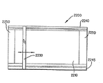
図21は本発明にしたがったフロアマットの別の実施形態を示している。フロアマット2100はまた洗浄可能/掻き落とし可能な部分2110とベース部分2120とを含んでいる。この実施形態では洗浄可能な部分2110はこの応用では前述したように、材料の断面全体にわたる構造において粘着性である材料からの単一の構造部材として形成されている。前述したように、均一で粘着性材料から部分2110を形成することによって、部分2110は洗浄されるためにベース部分2120から必ずしも取外される必要がない。しかしながら、前述したこの実施形態では、洗浄可能な部分2110は挿入部分の使用の結果として挿入部分の上部表面を腐食することにより洗浄される。図21の実施形態では、洗浄可能な部分はスクレーパ2130の使用により洗浄可能な部分2110から約2−3ミクロンの上部表面を掻き落とすことにより綺麗にされる。
【0080】
スクレーパ2130は任意の種々の構造を含むことができるが、絶対に必要なことは洗浄可能な部分2110から上部表面を取り除くことができるスクレーパである。例えば任意のタイプの掻き落とし表面、例えば切れ味の悪いナイフ、レーザまたは平面等がスクレーパ2130として使用されることができる。
【0081】
スクレーパ2130はトラック2140、2145上で移動可能である。トラック2140、2145は洗浄可能な部分2110およびベース部分2120に隣接している。スクレーパ2130はホイールまたは他の構造、例えばトラック2140、2145中の溝等の相補型構造内で受けられるピンを含んでいてもよい。したがってスクレーパ2130はトラック2140、2145で洗浄可能な部分2110を横切って移動可能である。スクレーパ2130は洗浄可能な部分2110を横切って可動であるスクレーパ部分2130上の掻き落とし表面だけを含んでいる。さらに、2つのトラックが使用されることは必要ではない。スクレーパは単一のトラック内で移動することも可能である。
【0082】
スクレーパ2130はトラック上でスクレーパを移動するためにスクレーパと結合するようにユーザの足を利用することを含んでいる任意の種々の方法により移動される。
フロアマット2100はまたトラック2140、2145の一端または両端部に含まれていてもよいごみため2150を含んでいる。ごみため2150はスクレーパ2130が洗浄可能な部分を掻き落とした後に洗浄可能な部分2110からの削り屑が配置される凹部を含んでいる。スクレーパ2130は洗浄可能な部分の削り屑をごみため2150に移動する。ごみために移動された洗浄可能な部分からの削り屑は例えばごみためから削り屑を吸取るか、取外すのが可能なごみためを取外して、ごみためから内容物を捨て、ごみためを再度設置することを含んでいる任意の種々の方法でごみためから除去される。
【0083】
理解されるように、洗浄可能な部分が削られるとき、スクレーパはトラック2140、2145上に同一基準で下げられ、それによって洗浄可能な部分と結合するスクレーパの表面は洗浄可能な部分と噛み合った状態である。このようにして例えばスクレーパがラチェット機構に取付けられ、したがってスクレーパがフロアマットの幅全体を横切って移動されるとき、スクレーパはラチェットがスクレーパを下げるようにラチェットを付勢する。その代わりに、スクレーパはトラックに関して同一の相対位置に存在し、トラックはベース部分と洗浄可能な部分に関して低い位置にラチェットを付けられる。さらに、スクレーパのブレード表面はスクレーパ構造に関して低くされ、それによってブレードは洗浄可能な部分とベース部分に関して移動されるが、スクレーパはトラック、洗浄可能な部分、ベース部分に関して同一の相対位置に存在する。
【0084】
さらに、ベース部分がフロアマット2100の実施形態で使用されるのを必要としない。洗浄可能な部分は単独で洗浄可能な部分に隣接するトラックと、トラックで可能のスクレーパと共に使用されることができる。ごみためは依然として使用される。このように図22はベース部分を使用しない洗浄可能な部分2210を含んでいるフロアマット2200の1実施形態を示している。洗浄可能な部分2210はトラック2240、2245に隣接している。スクレーパ2230はトラック2240、2245上で可動である。ごみため2250はトラック2240、2245の一端部または両端部に含まれてもよい。
【0085】
前述したように、濡れた時と乾燥時の両者で粘着性がある粘着性表面を与える単一の化学物質は知られておらず、これらの状態下では粘着性があまりない。したがって、本発明のさらに別の実施形態では、二重の化学物質が粘着性表面に使用される。二重の化学物質は2つの異なるタイプの粘着組成物を結合する。1つのタイプの粘着組成物は乾燥時に最適な粘着性である。他のタイプの粘着組成物は濡れた時に最適な粘着性である。組合わせて2つのタイプの粘着組成物は濡れた時と乾燥時の両者で最適な粘着性である上部の露出表面を与えるために使用されることができる。したがって人の靴が上部の露出表面と接触するとき、表面は乾いているときでも濡れているときでも良好な粘着性を与え、表面が濡れているときに人の滑りを阻止する作用を助長する。
【0086】
先の説明で使用されている“最適な粘着性”は、2つのタイプの粘着組成が乾いているとき、または濡れているときにある粘着性を保持し、一方のタイプは乾いた状態で最良またはサービス可能なレベルの粘着性を有し、他方のタイプは濡れた状態で最良またはサービス可能なレベルの粘着性を有することを意味している。
【0087】
2つのタイプの粘着組成物を含み、靴と接触する上部の露出された粘着性表面を与える材料は種々の実施形態を仮定することができる。例えば二重の化学物質の上部の露出された粘着性は前述され粘着性ではないベース部分と共動するように設計された挿入部分300 のような粘着性の“挿入”または“部分”の表面である。
【0088】
他方で、二重化学物質の上部の露出された粘着性表面はこのような粘着性の“挿入”または“部分”の表面ではない。むしろ二重化学物質の上部の露出された粘着性表面は実質上独立したフロアマットの使用可能な表面全体であってもよい。
二重化学物質の粘着性表面が粘着性ではない部分と組合わせて使用されても、あるいは実質上独立したフロアマットの使用可能な表面全体であっても、滑り防止コンポーネントの別々の構造部材は粘着性表面が濡れたとき粘着性表面の滑りを防止するために粘着性表面を伴って使用される必要はない。他方で、所望ならば、滑り防止コンポーネントの別々の構造部材は粘着性表面と共に使用されることもできる。
【0089】
通常、粘着性表面を与える材料はそれぞれ乾燥時に最適な粘着性であるか濡れた時に最適な粘着性である化学的性質を有するコンポーネントの組合わせを含み、それによって全体として組合わせは濡れた時または乾燥時に粘着性のサービス可能なレベルを保持する上部の露出された粘着性表面を与える。特に乾燥しているときに最適な粘着性である化学物質を有するコンポーネントの粘着性が水分の存在により減少されたとき、粘着力の損失は濡れた時に最適な粘着性である化学物質を有するコンポーネントにより補償される。他方で、濡れた時に最適な粘着性である化学物質を有するコンポーネントの粘着性が水分の欠如により減少されたとき、粘着力の損失は乾燥時に最適な粘着性である化学物質を有するコンポーネントにより補償される。
【0090】
コンポーネントはそれぞれ乾燥時に粘着性のある特性と濡れた時に粘着性のある特性を有する交錯した領域のパターンで結合される。コンポーネントは複合材料が異なる特性を有する領域にセグメント化されるように結合され、それによって材料は実質上均一ではない構造を有する。他方でコンポーネントは微細な粒状性であり、材料は実質上均一な構造を有する。
【0091】
図23は濡れた時と乾燥時のいずれでも粘着性である上部の露出された粘着性表面を与える材料を含んでいる多層アセンブリ10の1つの可能な実施形態を示している。層は上部層11を含み、これは濡れた時と乾燥時の両者で粘着性である上部の露出された粘着性表面を与える材料を具備している。材料は少なくとも3つのタイプの異なる“ドメイン”を含んでいる。上部層11の組成に関する“ドメイン”は他の別々な構成要素のセグメントとは異なる化学的特性を有している上部層のディスクリートな異なる構成要素セグメントを意味している。
【0092】
上部層11のドメインは圧力感応粘着特性と高い表面エネルギを有する粘着性ドメインを含んでいる。この粘着性ドメインは例えばアクリルメタクリレートの共重合体と、例えばアクリルアミド、エポキシアクリレート、またはウレタン終端されたアクリレートと圧力感応性ポリシロキサン誘導体の二官能単量体である。
【0093】
上部層11の第2のドメインは低い表面エネルギの粘着性ではない疎水性ドメインである。この粘着性ではない疎水性ドメインは例えばポリアクリルフルロロアクリレート、アクリル終端されたフルロロアクリルアミドまたはフルロロスルホンアミド、1または2のアクリレートグループで誘導されたポリシロキサン、アクリレートで誘導されたセルロース、スチレンブタジエン共重合体またはアクリルアクリレートまたはメタアクリレートを含んでいる。メタアクリレートは例えばシクロヘキサン、メタアクリレート、ノルボルナンメタアクリレート、またはイソボルニルメタアクリレートを含んでいる。
【0094】
上部層11の第3のドメインは親水性ドメインである。親水性ドメインは例えばヒドロキシエチルメタアクリレート、ポリアクリルおよびメタアクリル酸、それらの塩、ポリビニルアルコール、ポリオキシメチレン、ポリアミド、ポリエステル、飽和されていないジカルボン酸のポリイミドを含んでいる。
【0095】
上部層11では、粘着性ドメインはクロスリンクされ、親水性ドメインはクロスリンクされ、クロスリンク密度はそれぞれ5から20モルパーセントの範囲である。上部層の材料はフロアマットがサービス中である温度範囲ではエラストマーまたはレザー状態である。ガラス転移温度の所望の範囲は5−25℃である。
【0096】
上部層11では、複数の粘着性ドメインが複数の親水性ドメインと散在されている。親水性ドメインは乾燥状態の上部層11の粘着性を濡れた状態の上部層11の粘着性に実質上等しくさせることにより上部層11の全体的な粘着性を調節する。
低い表面エネルギの疎水性ドメインの機能は上部層にわたる水の連続的なフィルムの形成を阻止し、それ故排水率を増加することである。疎水性ドメインはまた上部層の粘着性の圧力依存性を強化し、それによって圧力のない場合に粘着性を減少する。これはフロアマットが実際に使用されるとき圧力が与えられたときの過度の粘着度の防止と、粘着性表面が過剰な量の浮遊する微粒子を集めることを防止するのを容易にする。
【0097】
重合体層11の全体的な形態はミセラ(miceller)であり、実質上層の表面でまたはその付近にある疎水性ドメインと、実質上層の表面より下の粘着性ドメインを有する。親水性および粘着性ドメインは濡れた状態下では表面に移動し、共に汚れおよび菌等を履物または綺麗にされる他の表面から吸引し濡れた時に粘着性表面の滑り防止を容易にするために必要とされる粘着性を与える。
【0098】
上部層11の製造では、ドメインの形成は溶剤誘導結晶化の使用により強化されることができる。粘着性部分の製造または組立ての選択された方法に基づいて、上部層11の押出し、積層またはアプリケーションプロセス中にドメインの選択的な方向付けによりさらに強化することが可能である。
【0099】
前述の上部層11に加えて、多層アセンブリ10は少なくとも1つの疎水性層12を含んでいる。その片面では、疎水性層12は上部層11に隣接している。疎水性層12は疎水性共重合体から作られる。このような疎水性共重合体の例にはメチルメタクリレート共重合体、スチレンブタジエン共重合体、ポリアルキルまたはポリアリレートシロキサンが含まれている。疎水性層12は例えばアクリル接着剤により上部層11に結合される。疎水性層のガラス転移温度は5−150℃の範囲である。
【0100】
疎水性層12は上部層11から水を効率よく移すように設計されている。疎水性層12の組成はそこでの水の可溶性を最小にし拡散性を最大にするように選択されている。疎水性層12の構成要素としてのポリシロキサンは特にこの視点から望ましい。この層の所望の機能は排水を容易にし相対的な乾燥を維持することであるので、水が存在する場合、疎水性層12の膨張特性を最小にすることも重要である。
【0101】
上部層11に隣接する表面と反対側の表面では、疎水性層12はポリビニルアルコール、ポリオキシメチレン、ポリハイドロキシエステルまたはアミドから作られた親水性層13に隣接している。この親水性層13のクロスリンク密度は10−30モルパーセントの範囲であり、そのガラス転移温度は−30℃乃至10℃の範囲である。
【0102】
親水性層13は疎水性層12によりそこに移された水を吸収することができる。親水性層13は隣接する層に接着結合される。親水性層による水の吸収はその厚さを増加する。親水性層の組成とクロスリンク密度は、この層が水の重量の2倍まで保持されるように選択される(膨張比200%)。親水性層の機能は蒸発による水の除去が遅いとき、貯水装置として作用することである。同時に、親水性層のクロスリンク密度と機能性はそれが水分を過剰に保持しないように慎重に制御される。
【0103】
多層アセンブリ10はさらにフロアと接触するための底部層14を含んでいる。底部層14はポリウレタン、スチレンブタジエン共重合体またはポリカーボネートのような耐摩耗性の滑り防止重合体から作られることができる。底部層14を形成するのに適切なその他の材料はアクリル終端アロマティックポリウレタンおよびエポキシを含んでいる。底部層14は通常高くクロスリンクされ(例えば10−50モルパーセント)、そのガラス転移温度は測定可能であるとき5℃よりも低く、いずれにせよ10℃よりも低い。底部層14は高い表面エネルギを有するように形成され、それによってフロア表面に水のフィルムが存在してもフロア表面の全ての親和性を失わない。
【0104】
多層アセンブリ10が独立したフロアマットとして使用されるならば、底部層14は特に有効である。他方で多層アセンブリ10が粘着性ではない部分と組合わせて挿入部分として使用されるならば、底部層14は存在しなくてもよい。代わりに、粘着性ではない部分と接触して、多層アセンブリ10と粘着性ではない部分との接触を確実にするために粘着剤は親水性層13の表面上で使用されてもよい。
【0105】
上部層11は厚さ約50−500ミクロンである。疎水性層12は厚さ約100−1000ミクロンであり、親水性層13は厚さ約250−1500ミクロンである。底部層14は厚さ約250−1500ミクロンである。
多層アセンブリ10は排水路を与えるためパターンをエンボスされ、排水を行うため穴のパターンを穿孔されることができる(直径2−10mm)。
【0106】
多層アセンブリ10は前述のそれぞれの層を別々に製造し、その後通常のプロセスを使用して共に結合することにより組立てられる。その代わりに、例えば上部層11が最初に製造され、他の層は上部層11および相互に連続的に与えられ、結合される。
別の代わりの実施形態によれば、上部層11は均一な組成を有する材料を具備している。均一な組成は材料がドメインに分割されないが、代わりにさらに微細に粒状にされ、材料が材料全体にわたって実質上一定である化学特性を有することを意味する。化学特性は粘着性を維持しながら材料が水を吸収できる特性である。
【0107】
例えば上部層11の均一な組成の材料はブロック共重合体またはグラフト共重合体のような重合体から作られる。重合体は圧力感応性の接着剤を被覆されるか、親水性単量体でグラフトされ、その後にさらにフルロロアクリレートでグラフトされる。その代わりに、均一な組成の材料は圧力感応性接着剤と、水を拘束するためのファイバまたは微小球等の親水性充填体との混合物を含んでいる。
【0108】
前述したように、多層アセンブリは排水性を改良するために穿孔される。図24は前述したように4つの層を具備する多層アセンブリ15で形成された穿孔パターンの1実施形態を示している。円形の穴16は全ての4つの層を通して打抜き、切断、または穿孔されている。円形の穴は例示として示されているが、穴は任意の形状でよい。
【0109】
本発明の付加的な実施形態は幾つかの任意のパターンで整列されている2つの基本的に異なる粘着組成物を使用している。第1の粘着組成物は圧力感応性で、乾燥時に粘着性である。第2の粘着組成物は親水性で濡れた時に粘着性である。パターンは第2の粘着組成物と交錯する第1の粘着組成物の領域のパターンである。乾燥時に粘着性の粘着剤の例はポリ(エチレン−コ−ビニルアセテート)とポリビニルブチラールを含んでいる。濡れた時に粘着性の粘着剤の例は親水コロイドガムと混合した可塑剤が存在する場合天然および合成ゴムを含む混合物と、以下のクラスの化学物質、即ち2つのアミノエチルエタアクリレートおよびn−ブチルメタアクリレートの共重合体を含んでいる。
【0110】
図25は前述したように2つの基本的に異なる粘着組成を使用している、多層アセンブリ17の断面の斜視図を示している。上部層18は乾燥時に粘着性の粘着剤と交錯する濡れた時に粘着性の粘着剤のチェッカボードパターン19を有している。チェッカボードパターンは例示の目的のみで示され、他の交錯パターンも本発明で考慮されることができる。下部層20はフロアに接触するため耐摩耗性の滑り防止層である。下部層20は多層アセンブリ17が独立したフロアマットとして使用されるならば特に有効である。他方で、多層アセンブリ17が粘着性ではない部分と組み合わせた挿入部分として使用されるならば、下部層20は存在しなくてもよい。代わりに、粘着剤は粘着性ではない部分と接触するため層18の表面で使用される。
【0111】
図26は本発明のさらに別の実施形態を示している多層アセンブリの断面の斜視図である。上部層22は乾燥しているときに粘着性の粘着剤を具備している。第2の層23は濡れた時に粘着性の粘着剤を具備している。下部層24はフロアと接触する耐摩耗性の滑り防止層である。
【0112】
穴25は靴底またはその他の表面による接触が濡れた時に粘着性の粘着剤により清浄にされことを可能にし、同時に濡れた時に粘着性の粘着剤が接触されるように上部層22に形成される。第2の層23も親水性であるので、濡れた時に膨張し、穴25を満たし、靴底等の綺麗にされる表面が、濡れた時に粘着性の粘着剤へより多く接触する。
【0113】
図27は上部の露出された粘着性表面を与える材料が実質上均一の組成を有する別の実施形態を示している。材料は乾燥時に粘着性の材料と濡れた時に粘着性の材料との混合物で構成されている。濡れた時に粘着性の材料はある親水ガム(例えばガウアガム、イナゴマメガム等)を含んでいる。これらの親水ガムは水分を吸収する大きい容量を有するので、これらは良好な濡れ粘着性または接着性を与える。圧力感応性でもある乾燥時に接着性の材料は可塑剤が存在する場合、合成および/または天然ゴムを含む。合成および/または天然ゴムは例えばポリイソブチレン、天然ゴム、シリコンゴム、アクリロニトリルゴム、ポリウレタンゴム、ブチルゴムエラストマー等である。
【0114】
前述したように濡れた時に粘着性で乾燥時に粘着性の材料の混合物の強度および均一度は混合物に凝集性を強化する物質を導入することにより増加される。凝集性を強化する物質は例えば木材セルロース、コットンまたはダクロンのような1以上の天然および人口繊維材料である。
【0115】
図27では、多層アセンブリ26の上部層27は凝集性を強化する物質と混合された圧力感応性の乾燥粘着剤と親水コロイドガムとの混合物で構成されている。凝集性を強化した物質により、上部層27の表面28は単一材料の均一な外観を有する。下部層29はフロアと接触するための耐摩耗性の滑り防止層である。下部層29は層27が挿入部分として使用されるならば存在しなくてもよい。
【0116】
前述したように、濡れた時および乾燥時に粘着性である上部の露出された粘着性表面を与える任意の材料は相互に組み合わせて使用されるか、説明した任意の他の層と組み合わせて使用されることができる。例えば層18または27のいずれかが疎水性および親水性の層と組み合わせて使用されることができる。
【0117】
本発明にしたがった実施形態では、排水能力はマットに捕らえられる水分の不所望の効果を緩和するために与えられる。マットで捕らえられた水分はかび、菌または藻類の成長を生成する。このようなかび、菌または藻類はしばしば人が経験するあるアレルギー反応その他の病気の原因である。病気の潜在的な危険性に加えて、捕らえられた水分はマット付近または周辺で不快な臭いも生じる。
【0118】
図28Aでは、マット支持体および排水構造30の例が示されている、マット支持体および排水構造はそこに置かれるフロアマットを支持し実質上そのレベルを維持するための支持部材31を含んでいる。支持部材31は放射状に配置されてもよい。そこに置かれたマットと接触するための支持部材31の上部表面は実質上同一平面上である。支持部材の対の間には、表面と接触する水を下方向に誘導し水がマット支持体および排水構造のエッジへ排水されることを可能にする勾配面または表面32が存在する。実施形態はマット支持体および排水構造の1以上のエッジ付近に保持貯水器33を含んでいる。壁112 は勾配表面の1側面で支持部材上に配置されている。他の実施形態では、図28Cと32のBで示されているように、保持貯水器は使用されていない。
【0119】
傾斜部111 はマット支持体および排水構造上で人が躓かないようにするために壁112 に形成されている。勾配と傾斜部の程度はマット支持体および排水構造の高さと寸法に応じて変化される。示されている傾斜部は単なる例示であり、他の傾斜部の形態および寸法も可能であり、当業者によく知られている。
【0120】
マット支持体および排水構造30は任意の数の材料、例えばプラスティックまたはゴムから作られることができる。マット支持体および排水構造30はモールドされ、熱成形され、型押しされるか、材料の選択肢と製造されるピースの数に応じてその他の方法で製造される。
【0121】
図28Bは、マット支持体および排水構造の別の可能な実施形態を示している。マット支持体および排水構造34は重力により排水を行う複数の勾配表面36を有する壁35を具備している。表面36等の複数の勾配表面をここでは“重力部分”と呼ぶ。表面36はマット支持体および排水構造の表面99と勾配表面との間に位置する支持部材37により支持される。図28の実施形態では、支持部材37の上部表面は実質上勾配表面36と同一平面上である(即ち支持部材は図28Aの実施形態のように勾配表面の平面を超えて突出しない)。水分が表面36と接触するとき、これはこれらの表面に沿って保持貯水器38まで流れ落ち、保持貯水器38はマット支持体および排水構造34の重力部分の周縁の境界を定めている。
【0122】
図28Bで示されている実施形態では、マット支持体および排水構造34上に位置されるマットは隣接する表面36と、マット支持体および排水構造の壁35により形成される頂点100 により支持される。横断部材はマットの付加的な支持体を与えるために付加される。この付加的な支持体は比較的に頑丈な構造の小さいマットでは必ずしも必要とされない。
【0123】
図28Cはマット支持体および排水構造が保持貯水器をもたない1例を示している。ここではマット支持体および排水構造39は水がマット支持体および排水構造の1以上の端部40から自由に流れ出るように構成されている。このタイプのベースは屋外の使用に設計されたマットによって使用されるのに好ましい。
【0124】
図28Bと28Cに記載されている実施形態では、重力部分は支持部材により支持されているように示されている。その代わりに、重力部分はまた所望された重力で水を流れさせるように可変の厚さの単一ピースの材料から作られることもできる。このような構造はより多くの材料を必要とするが、このような構造は製造がより簡単である。1ピースの重力部分を含んでいるマット支持体および排水構造の1例が図28Dに示されている。マット支持体および排水構造3000を示している図28Dでは、重力部分3001は厚さがそのエッジ3003方向に減少する単一ピースの材料から製造される。単一ピースの材料はその中心またはその付近の頂点3002で最大の厚さを有する。単一ピースの材料はしたがって接触する水を下方向に誘導するために頂点を形成する2つの隣接する勾配表面を与える。
【0125】
マット支持体および排水構造3000は重力部分3001の頂点3002と壁3004でそこに位置されるマットを支持する。横断部材3005はマットが特に大きいならばマットの付加的な支持体として使用されてもよい。マット支持体および排水構造3000は保持貯水器3006を有するものとして示されているが、これはマットが屋外で使用される場合には必要とされない。
【0126】
重力部分3001について示されている以外の重力部分の形状も前述したように排水に適している。例えば反転された鉢形または3以上の側面のピラミッドは前述の排水のための重力機能を行う幾つかの他の形状である。
図29は例えば図28A−Dで説明されたマット支持体および排水構造の1つへマットを配置している状態を示している。図29の例では、マット42はマット支持体および排水構造43の露出領域だけがマット42の端部の保持貯水器のセクションであるようにマット支持体および排水構造43の寸法が定められている。マット42の寸法の決定は水がマット下で捕らえられた状態であるのではなく露出された保持貯水器から蒸発することを可能にする。屋外の使用では、この露出された保持貯水器は必要ではなく、このようなケースでは、マット42はマット支持体および排水構造の全体的な上部の露出表面にわたって延在するような寸法にされる。さらに、屋外での使用では、マット支持体および排水構造の壁はマット支持体および排水構造の側面から取外され、水が例えば何等の損傷も起こす可能性が少ない屋外の階段または屋外へ流れることを可能にする。しかしながら、保持貯水器は屋外でも同様に使用されることができることに注意すべきである。
【0127】
マット42はマット支持体および排水構造と共動する任意の種々の形態で実施される。マット42は例えば任意の市場で入手可能なフロアマットである。代わりにマット42はここで説明したフロアマットまたはここで説明したフロアマットのコンポーネントの任意の実施形態であってもよい。例えば、マット42は唯一の粘着性部分、唯一の粘着性ではない部分を具備するか、粘着性部分と粘着性ではない部分の組合わせであってもよい。あるいはマット42は単一層、または前述したように乾燥時に粘着性で濡れた時に粘着性の多層のマットであってもよい。マット42はベース部分を含んでいてもよい。マット支持体および排水構造は前述したようにマット42の任意の実施形態から分離されているか、またはマット42と一体化して形成される。
【0128】
図30は本発明にしたがった別の代わりの実施形態を示している。図30では、マットの配置44はマット支持体および排水構造と共動する粘着性ではない部分45と粘着性部分49とを備えている。このマットの配置では、吸水性で水はけ特性の粘着性ではない部分45はマット支持体および排水構造46の重力部分47上に位置されている。重力部分47に隣接するマット支持体および排水構造46の実質上平面のセクション48は粘着性部分49を受けるように構成されている。粘着性部分49は単一層または複数の層であり、平面セクション48の一部分だけをカバーしてもよい。複数の層は分離可能で、廃棄可能な粘着性シートであってもよい。凹部は平面セクション48に形成され、単一層または多層の粘着性部分49を受けるように構成されている。代わりに、粘着性部分49は単一層または複数の層として平面セクション48全体に延在し、粘着性ではない部分45と接触していてもよい。
【0129】
マット支持体および排水構造46と共動するマットは図30に示されているように別々の粘着性ではない部分と粘着性部分とを必要としない。代わりに、マット支持体および排水構造46と共動するマットは重力部分47を覆って位置されるように構成された粘着性ではない吸水部分と、平面セクション48を覆って位置されるように構成された粘着性部分とを有する単一の一体化された部材であってもよい。
【0130】
前述したように粘着性ではない吸水部分を重力部分上に位置付けることにより、吸水部分から排水される水は蒸発するかその他の方法で除去されるまでマット支持体および排水構造に蓄えられる。一方、粘着性部分はその前面に置かれるマットの吸水部分のために、マットに接近する人に関して比較的乾いている。
【0131】
別の実施形態では、粘着性および粘着性ではない部分の両者は重力部分を覆って位置される。図31はこのような配置を示している。図31では、マットの配置50は粘着性ではない吸水部分51と、マット支持体および排水構造54の重力部分53上に位置されている保持貯水器を含む粘着性部分52との両者を含んでいる。
【0132】
粘着性部分52は前述したように単一層または複数の層であることができる。粘着性部分52はまた以下の支持体および排水構造へ水を通過させるように水はけまたは吸水特性を有する。粘着性ではない部分51と粘着性部分52は単一の一体化したピースであってもよい。
【0133】
マット支持体および排水構造はこれらが十分に重い材料から作られているならば、時間にわたって摩耗し交換されるので多数のマットと共に使用されることができる。
マット支持体および排水構造の別の実施形態が図32のAで示されている。この実施形態では、マット支持体および排水構造55はその中心または中心付近に頂点101 を形成するように配置された2つの勾配表面57から形成されるAフレーム構造を具備している。Aフレーム構造と接触する水は前述したように重力の作用によりマット支持体および排水構造55の端部の保持貯水器58へ排水される。この実施形態では、マット支持体および排水構造はそこに位置するマットへ付加的な支持体を与えるために付加的な横断部材59を形成されてもよい。マットが合理的に小さく頑丈ならば、交差する部材は必要ない。
【0134】
屋外の使用では、マット支持体および排水構造は保持貯水器を必要としない。このような例は図32のBに示されている。この図面では、マット支持体および排水構造60は保持貯水器をもたず、水はマット支持体および排水構造の端部61の1つから自由に流れ出ることができる。
【0135】
平面図では、マット支持体および排水構造は2つの長い側面と2つの短い側面を有する四辺形である。短い側面はここでは“端部”と呼ばれる。2つの長い側面の間の距離はマット支持体および排水構造の幅であり、2つの端部の間の距離はマット支持体および排水構造の長さである。前述の説明を考慮すると、図32のAに関連して説明したようにAフレーム構造の勾配表面がマット支持体および排水構造の端部方向ではなくその長い側面方向へ傾斜するように方向付けされているマット支持体および排水構造を構成することも可能である。このようなマット支持体および排水構造は図32のCに示されている。この実施形態では、2つの勾配表面63はマット支持体および排水構造の(端部に関して)中心領域またはその付近に頂点を形成するように配置されている。Aフレーム構造の勾配でない平面の外周103 はAフレーム構造と、マット支持体および排水構造の壁との間に延在する。2つの勾配表面63から流れ落ちる水はAフレーム構造と壁との間の傾斜していない平面外周に保持される。代わりに、Aフレーム構造はマット支持体および排水構造の幅全体を横切って延在する。この実施形態では、保持貯水器だけがマット支持体および排水構造の端部に存在する。
【0136】
図33はマット66の上部部分をマット支持体および排水構造67上に位置させた図を示している。マットはその支持体および排水構造67上に位置付けられたとき、マット支持体および排水構造の露出された領域だけが一方の端部の貯水器の小さいセクションであるように寸法を決めされている。これは水がマットの下に捕らえられるのではなく蒸発することを可能にする。
【0137】
マット中の水分の保持を実効的に管理する方法の別の例は図34に示されている。この実施形態では、マット68は主として2層システムとして示されている。マットの上部層は前述したように例えば乾燥しているときに粘着性の材料および濡れた時に粘着性の材料を具備している。しかしながら上部層は任意の特定の種類の材料に限定されない。下部層は上部層に隣接する上部表面にチャンネルが形成されてマットの幅に沿って延在しているフレキシブルなまたは頑丈な材料である。拡大された断面図34−34は、十分な重量がマットに加えられたとき、マットの側面を通じて排水を行うようにマットの幅に沿って形成されたチャンネル71にわたって直接的にマットに穿孔70を配置した図を示している。多層のマットが示されているが、図34で示されているようにチャンネルを有する下部層と組合わせて上部層として穿孔を有する単一層マットを使用することも可能である。
【0138】
図35は図34と共に説明されているマット支持体および排水構造の使用を図示している配置72を示している。この実施形態では、マット支持体および排水構造はそれぞれ一方の端部に保持貯水器73、74を有する。マットの排水の詳細は前述し拡大断面図35−35で図示されているとおりである。マット支持体および排水構造は排水がマット68自体により行われるので重力部分を含む必要はない。
【0139】
水分の除去を管理するように設計されたマットのさらに別の実施形態は図36に示されている。この実施形態ではマット77は3層を具備している。拡大断面図36−36はマット77の機能を示している。上部層79は薄膜層であり、例えばプラスティック等または前述したようにキャリア基体を覆って粘着性の滑り防止表面を有する薄膜層の積層体から形成されている。しかしながら上部層79は任意の特定の種類の材料に限定されない。マットの上部層は水分がマットの中間層81へ上部層を貫通することを可能にする穴80を穿孔されている。中間層81は吸水材料を有する。このような材料は中間層が水の重量の2倍まで保持できるように選択され(膨張比200%)、例えばオープンセル発泡体ゴムまたは発泡プラスティック、非常に親水性の重合体または天然および/または人工ファイバまたは繊維から構成される。吸水層81はマットの幅を横切って延在する小さいチャンネル82と共に構成される。これらのチャンネルは形状が円筒形として示されているが、オープンチャンネルを生成する任意の形態が考慮される。
【0140】
マット77の下部層83は前述したように、ゴムまたはプラスティックのような頑丈な材料であり、下部層と接触表面、例えばマット支持体および排水構造の表面との間に滑りに対する抵抗を与える。例えば人がマットに踏込むことにより重量がマットの上部層に与えられるとき、中間の吸水層81に蓄えられた過剰な水と湿度は吸水層のチャンネル82を通ってマットの側面から排出される。チャンネルはマットの中心またはその付近のチャンネル中の点がマットの側面のチャンネル端部よりも僅かに高いように形成され、それによってチャンネルに対して角度を生成する。これはマット上に与えられた重量がない場合にマットからの排水を行い、またマット表面に加えられた重量による水分の排水を容易にする。
【0141】
図37は図36に関連して説明されたマット77を有するマット支持体および排水構造の使用を示した配置84を示している。この実施形態では、マット支持体および排水構造はそれぞれ端部に保持貯水器85、86を有する。マットの排水の詳細は前述したものと同様に拡大された断面図37−37で示されているとおりである。図35の実施形態のように、マット支持体および排水構造は排水がマット77自体により行われるので重量部分を含む必要はない。
【0142】
吸水層中にチャンネルを配置する別の構成は吸水ファイバを使用し、重量が加えられる場合に水が主としてファイバの長さ方向に流れてマットの側面を出るように好ましくはこれらをマットの幅に沿って方向付けすることである。吸水層中でのファイバの使用が図38に示されている。
【0143】
ファイバが使用される場合、マット88は3つの層を具備している。拡大された断面図38−38はマット88の機能を示している。上部層90は薄膜層であり、例えばプラスティック等で形成され、または前述したようにキャリア基体を覆って粘着性の滑り防止表面を有する薄膜層の積層から形成される。しかしながら上部層は特定の種類の材料に限定されない。マットの上部層は湿気がマットの中間層92へフィルムを貫通して侵入することを可能にする穴91を穿孔されている。中間層92は吸水ファイバ93を有する。これらのファイバは例えばプラスティック、非常に親水性の重合体または天然および/または人工材料から形成される。吸水層92のファイバはマットの幅に沿って方向付けされ、したがってファイバ間の空間とファイバ自体はマットの幅を横切って延在するチャンネルを形成する。
【0144】
マット88の下部層94は、ゴムまたはプラスティックのような頑丈な材料で構成され、下部層とそれに接触する表面との間で滑りに対する抵抗を与える。例えば人がマットに踏込むことにより重量がマットの上部層に与えられるとき、中間の吸水層92に蓄えられた過剰な水と湿度はファイバ93の間の空間により生成されるチャンネルと恐らくファイバ自体を通ってマットの側面から排出される。幾つかまたは全てのファイバもまたマットの中心またはその付近の点でファイバがマットの側面のチャンネル端部よりも僅かに高くされるようにマットに位置付けられ、それによってファイバに対して角度を生成する。これはマット上に与えられた重量がない場合にもマットからの排水を行い、またマット表面に加えられた重量による水分の排水を付加的に助ける。
【0145】
図39は図38と関連して説明されたマット88を有するマット支持体および排水構造の使用を示した整列95を示している。この実施形態では、マット支持体および排水構造はそれぞれ一方の端部に保持貯水器96、97を有する。マットの排水の詳細は前述したように拡大された断面図39−39で示されている。図35、37の実施形態のように、マット支持体および排水構造は排水がマット88自体により行われるので重量部分を含む必要はない。
【0146】
図40は本発明の別の可能な実施形態を示している。図40では、配置400 はベース部分200 に関連して前述したように水放散、吸水、水はけ特性を有するベース部分403 を含んだマット402 を受けるように構成されているマット支持体および排水構造を具備している。マット402 はさらに粘着性挿入部分404 と滑り防止コンポーネント405 を含んでいる。滑り防止コンポーネントは例えば図18で示されているように粘着性挿入部分404 の開口を通ってマット402 のベース部分から延在する踏面であってもよい。粘着性挿入部分404 は単一層であってもよく、また複数の別々の層であってもよい。
【0147】
別の実施形態によると、図示されていないが、マット支持体および排水構造401 自体は粘着性挿入部分がそこに置かれたとき粘着性挿入部分の開口を通じて延在する滑り防止コンポーネントを構成する。
全ての前述の実施形態では、マット支持体および排水構造における可能な水の停滞特性と、そこに位置するマットに潜在的に残る水分と吸水特性を有するために、抗真菌剤、抗菌剤および/または芳香剤の付加は付加的な利点を与え、このような薬剤およびまたは芳香剤を含む構成が本発明に含まれる。このような薬剤およびまたは芳香剤はマット支持体および排水構造および/またはマットをモールドまたは製造する前にマット部分の材料中に含有される。その代わりに薬剤および芳香剤はそれらをマット支持体および排水構造および/またはマットへスプレーし、浸し、ブラッシングまたは散布することにより製造後に与えられてもよい。
【0148】
したがって前述したように、本発明のフロアマットは以下の特徴を含んでいる。以下列挙する特徴は本発明のフロアマットの包括的特徴ではないことに注意すべきである。この説明は全体において本発明のフロアマットの全ての特徴を説明している。
前述したように、1実施形態では、フロアマットは表面領域のある上部の露出された表面を有する粘着性表面を含んでおり、実質上紙ではない滑り防止コンポーネントは濡れた時に粘着性表面上の滑りを防止するため粘着性表面の上部の露出された表面の表面領域内に配置されている。したがって滑り防止コンポーネントが上部の露出された表面が濡れた時にそこに踏み入れた人の滑りを減少するために粘着性表面の上部の露出された表面と動作可能に関連している。滑り防止コンポーネントは上部の露出された表面に一体的に含まれてもよい。
【0149】
滑り防止コンポーネントは接着性ではない材料からなる図5で見ることができる複数のチャンネルを含んでおり、ここでは複数のチャンネルは粘着性表面に人が踏み入れることに応答して粘着性表面の上部表面から延長可能である。代わりに、フロアマットは先に説明した踏面等の粘着性表面に立っている人がいない場合に粘着性表面の上部表面から突出可能な滑り防止コンポーネントを含んでもよい。したがって踏面は細長い部材であり、その長さは粘着性表面の上部の露出された表面を超えて突出する長さよりも実質的に長い粘着性表面の上部の露出された表面を横切って延在する長さである。
【0150】
さらに、滑り防止コンポーネントは図11に示されている開口である。
滑り防止コンポーネントの種々の実施形態は粘着性ではない材料、例えば粘着性ではない部材と耐水性材料からなる。したがって、滑り防止コンポーネントは耐水性であってもよい。滑り防止コンポーネントはまたこれらが複数回の使用後に粘着性表面での滑りを阻止するための機能を残すような材料からなる。このように、滑り防止コンポーネントは十分に頑丈な材料からなり、それによって滑り防止コンポーネントの構造は人により複数回踏まれた後に実質上維持され、人より複数回踏まれた後に実質上維持される組成を有する材料からなる。
【0151】
前述したように、1実施形態ではフロアマットは、人の靴底に接触する粘着性ではない露出された上部表面領域250 と、ベース部分の粘着性ではない露出された上部表面領域に関連する粘着性部分とを有し、靴底に接触する粘着性の露出された上部表面部分350 とを有するベース部分を含んでいる。少なくとも図1で見られるように、ベース部分の粘着性ではない露出された上部表面領域250 は少なくとも粘着性部分の粘着性の露出された上部表面領域350 と同程度の大きさである。
【0152】
フロアマットのベース部分は人の靴がベース部分と粘着性部分に圧力を加えたときに、ベース部分と粘着性部分の両者は人の靴の下部の形態に適合するように衝撃吸収コンポーネントを含んでいる。粘着性部分はその部分の下側にも粘着性表面を含んでいる。
【0153】
種々の実施形態では、ベース部分は図1で示されるように粘着性部分を制限するか、図14で見られるように粘着性部分に隣接して位置されてもよい。
少なくとも図1で見られるように、フロアマットは人の靴底に接触するための連続的な粘着性ではない露出された上部表面領域250 と、人の靴底に接触するための粘着性の露出された上部表面領域350 を有する粘着性部分とを有するベース部分を有する。図15および16でも見られるように、ベース部分の粘着性ではない露出された上部表面領域と、粘着性部分の粘着性の露出された上部表面領域の寸法は両者とも大人の寸法の靴の靴底全体がそこで受けられることが可能な寸法である。ベース部分の連続的な粘着性ではない露出された上部表面領域250 は粘着性部分の粘着性の露出された上部表面領域の第1の側部352 に配置された第1の側の領域252 と、反対側の粘着性部分の粘着性の露出された上部表面領域の第2の側部354 に配置された第2の側の領域254 とを有する。ベース部分の連続的な粘着性ではない露出された上部表面領域の第1の側の領域は、ベース部分の連続的な粘着性ではない露出された上部表面領域の第2の側の領域よりも大きい。
【0154】
背景技術の説明で前述したように、人は店内の1つまたは複数の物品の位置を知る能力がないので困惑する。店の案内は知られているが、これらが伝えられる情報量は空間の制限により限定される。明らかに、所望の品物の位置へ顧客を容易に、都合よく誘導する必要がある。
【0155】
前述の要求を解決するため、本発明のさらに別の実施形態によれば、フロアマットはディスプレイ装置および/または音声発生装置へ結合されたスピーチ認識装置に結合されている音声感知装置に関連される。音声感知装置、スピーチ認識装置、ディスプレイ装置および/または音声発生装置は店で探されている品物の名称または説明を含む人の発話に応答して表示および/または可聴応答を発生するように構成されてもよい。
【0156】
特に、音声感知装置は発話されたスピーチを検出し、そのスピーチをスピーチ認識装置へ転送される電気信号へ変換するように構成される。スピーチ認識装置はスピーチ中に含まれている用語に対応した動作を行うように、音声感知装置から受信された信号を処理するように構成されている。動作は用語に対応する表示の生成および/または用語に対する可聴応答の発生を含んでいる。スピーチ認識装置は表示を形成するためにディスプレイ装置へ、または可聴応答を発生するために音声発生装置へ、または電子ディスプレイ装置と音声発生装置の両者へ結合される。
【0157】
1つの可能な応用では、フロアマット、音声感知装置、スピーチ認識装置、ディスプレイ装置および/または音声発生装置はビジネスの場所、例えばスーパーマーケット等の小売店に配置される。ディスプレイ装置はフロアマット中に含まれ、フロアマットおよび音声感知装置は店内または店外の店の入口近くに位置される。音声感知装置は合理的な距離内にいる人が発話した用語が容易に検出可能であるようなレベル、例えば地面またはフロアレベルから4乃至6フィートの距離に置かれる。任意の支持手段が音声感知装置の保持に使用されてもよい。例えば音声感知装置は独立したスタンドに支持されるか、または別の構造から懸架されてもよい。
【0158】
本発明を使用するため、店を訪れる人はフロアマットに接近し、フロアマット付近またはその上に立つ。音声感知装置は明白に指示される。人が音声感知装置の通常の方向で、発話が音声感知装置から検出可能である距離からその人が探している品物の名称または説明を発話する。音声感知装置はその発話を検出し、それを音声認識装置へ伝送される電気信号へ変換する。スピーチ認識装置は音声感知装置に近接して位置されるか、音声感知装置から離れて位置される。スピーチ認識装置は配線導体または光ファイバ等による接続または超音波、赤外線または無線周波数(RF)放射等の無線接続により音声感知装置へ結合される。
【0159】
スピーチ認識装置へ送信される信号はそこから情報を抽出し、その情報に対応する少なくとも1つの動作を行うように処理される。例えばスピーチ認識装置はもとの発話の1または複数の用語を識別するために信号を処理し、その用語は典型的には店で探されている品物の名称または説明である。品物の名称または説明が識別されたとき、スピーチ認識装置は店内の品物の名称または説明をそれらのそれぞれの位置に相関するデータベースを検索する。発話中で識別された品物がデータベース中で発見されたならば、スピーチ認識装置は店内のその品物の位置を特定するデータベースから情報を検索する。スピーチ認識装置はその後、ディスプレイ装置でその位置情報を表示するか(例えばコンピュータ処理される幾つかの形態のスピーチ合成を使用して)、位置情報を特定する可聴信号を発生するか、あるいはその両者を行う。
【0160】
ディスプレイ装置は文字数字の符号の形態で位置情報を表示する。例えば音声感知装置の方向における用語“pasta ”、“dog food”、“potato chips”という人の発話に応答して、スピーチ認識装置はディスプレイ装置に以下の表示を生成する。
“...PASTA-AISLE 6 ON LEFT...DOG FOOD-AISLE 2 ON RIGHT...POTATO CHIPS-END OF AISLE 9 AT REAR... ”
探している品物の名称または説明および位置と共に、ディスプレイ装置は関連する販売および広告情報を表示する。例えば前述の例のディスプレイに加えて、以下の表示が生成される。
“...ALPO DOG FOOD ON SALE TODAY, 55 CENTS PER CAN...LAY'S POTATO CHIPS-8 OUNCE BAG-$1.49...”
この特徴は売主に付加的な歳入を発生する。
【0161】
数字文字単独の表示の代りに、ディスプレイは店のレイアウトのグラフィック表示の形態であり、所望の品物の位置を目立たせるようにしてもよい。
さらに別の構成として、前述したように音声発生装置は独立してまたは可視ディスプレイを伴って人の発話に対して可聴的に応答してもよい。可聴応答は発話で指名または説明された品物の位置を特定する。可聴応答は例えばコンピュータ生成され、または予め記録された可聴データベースから検索されることができる。
【0162】
音声感知装置、スピーチ認識装置、ディスプレイ装置、音声発生装置は任意の数の既知の市場で入手可能な製品で構成されることができる。音声感知装置は例えば任意の寸法のマイクロホンである。特に音声感知装置は指向性マイクロホンであり、即ちマイクロホンの方向に意図的に指向される発話をランダムな環境雑音からより良好に分離するために良好に限定された指向性応答特性を有するマイクロホンである。使用される市販の指向性マイクロホンの例にはカージオイドマイクロホン、スーパーカージオイドマイクロホン、ショットガンマイクロホン等が含まれる。カージオイドマイクロホンの例はDPA (商標名) 4021 型、Earthworks(商標名)A30X、Shure (商標名)SM57である。スーパーカージオイドマイクロホンの例はPeavey(商標名)PVM 480 とElectrovoice(商標名)ND767Aである。ショットガンマイクロホンの例はBeyerdynamic(商標名)MCE86 S.1 、Sennheizer(商標名)K6 ME66 、Shure (商標名)SM89である。マイクロホンが使用された環境の騒々しさに応じて、より高い指向性のマイクロホンは指向性の低いマイクロホンよりも良好な結果を生む。例えば非常に騒々しい環境では、スーパーカージオイドまたはショットガンマイクロホンのような高い指向性のマイクロホンが好ましい。
【0163】
別の実施形態によれば、音声感知装置はディスプレイ装置に組込まれるか、フロアマットに取付けられ或いはそこに埋設される。音声感知装置は例えばフロアマット中に埋設されたマイクロホンアレイであってもよい。よく知られているように、マイクロホンのアレイ、例えば2以上、好ましくは4の全方向性のエレクトレットマイクロホンは音声の方向に応答する音声感知システムを提供するように配置されることができる。マイクロホンのアレイの使用はアレイがマットに過剰な厚さを付加せずにマットに埋設されることができるので、空間を節約する問題を解決する。
【0164】
音声認識装置は音声感知装置から受信された信号に応答してスピーチ認識ソフトウェアを実行するように構成されているコンピュータプロセッサおよびメモリを含むことができる。スピーチ認識ソフトウェアは実行されるときそこから情報を抽出するために信号を処理し、特にスピーチ認識ソフトウェアはもとの発話で話された用語を識別する。識別された用語により、コンピュータプロセッサおよびメモリはその用語の名称または説明したアイテムが店内で販売されているか否かを決定するソフトウェアを実行するようにさらに構成されている。販売されているならば、ソフトウェアは発話で指名されまたは説明された品物をデータベースで検索するように実行され、店内で販売されている品物をそれらのそれぞれの位置と相関させる。スピーチ認識装置はその後、指名されまたは説明された品物の位置を識別するデータベースから検索された情報をディスプレイ装置で表示させおよび/または音声発生装置により可聴で伝送させる。スピーチ認識装置は例えばスピーチ合成ソフトウェアを実行するか、音声発生装置により人間のスピーチの可聴ファクシミリを発生するようにスピーチコンポーネントの予め記録された可聴データベースをアクセスする。
【0165】
スピーチ認識装置はさらに、例えば不明瞭または曖昧な音声を検出するエラールーチンを実行し、対応するメッセージを表示し、または可聴音で発生し、発話が反復されるようにリクエストする。あるいは、例えば、指名されたまたは説明された品物が入手可能ではないならば、スピーチ認識装置は“NOT AVAILABLE ”または“OUT OF STOCK”等の対応するメッセージを発生する。
【0166】
市場で入手可能なスピーチ認識ソフトウェアの例にはL&H Dragon Natually Speaking(商標名)およびIBM ViaVoice(商標名)が含まれている。通常のプロセッサ/メモリの組合わせを有するソフトウェアを実行することに加えてまたはその代りとして、スピーチ認識装置の機能はASIC(Application Specific Integrated Circuit )または回路論理装置にプログラムされた必要な機能を有するASICのような特定化されたハードウェアで構成されることができる。
【0167】
ディスプレイ装置は任意の多数の形態で構成されることができる。ディスプレイ装置は例えば前述したように液晶ディスプレイ等の電子的に変更可能なディスプレイ表面を含んでいる。ディスプレイ装置はコンピュータ(例えばプロセッサおよびメモリおよび/またはASICを有するスピーチ認識装置)に接続され、コンピュータ生成イメージが前述したようにディスプレイ上に表示される。ディスプレイ装置とスピーチ認識装置間の接続は有線または無線で行われることができる。代わりに、スピーチ認識装置はディスプレイ装置中に組込まれてもよい。
【0168】
さらに前述したように、ディスプレイ装置は凹部210 内に含まれる等、フロアマット100 のベース部分200 に関連されるか、あるいは挿入部分300 の上方に面する底部表面上に含まれてもよい。その代わりに、ディスプレイ装置はベース部分または挿入部分のいずれかと共に一体化して形成されることもできる。ディスプレイ装置で生成されたイメージは通常固定した位置で表示され、またはディスプレイを横切ってスクロールすることができる。ディスプレイ装置は前述したように発光重合体、電子インクまたは電子ペーパーを含んでいてもよい。ディスプレイ装置は発光ダイオード(LED)、有機LED、エレクトロルミネセンス材料、プラズマディスプレイ、または任意の他の可視ディスプレイ放射または反射光を含んでいる。
【0169】
音声発生装置は任意のサイズの1以上のスピーカの形態で構成され、有線または無線接続によりスピーチ認識装置に結合される。スピーカは例えばディスプレイ装置またはフロアマット中に構成されたピエゾ電気平面パネルスピーカである。
図40は食品雑貨店を訪れた人が本発明を使用している本発明の前述の説明の応用を示している。人4000の発話が音声感知装置4001により検出可能であるように音声感知装置4001の感知距離内に位置する人4000は発話4004を発声する。発話4004は図示の例では用語“パスタ”である。
【0170】
音声感知装置4001はその発話4004を無線接続4008または有線接続4009によりスピーチ認識装置4002へ転送される電気信号に変換する。スピーチ認識装置4002はそこから用語“パスタ”を抽出するために信号を処理する。その後、有線接続4013または無線接続4012により、スピーチ認識装置4002は店内のパスタの位置を特定する応答ディスプレイ4007の“通路6 ”をフロアマット100 に含まれるディスプレイ装置4006に表示させる。さらに、またはその代わりに、有線接続4011または無線接続4010により、スピーチ認識装置4002は可聴応答4005の“通路6 ”を音声発生装置4003により発生させる。
【0171】
特に図41に示されているように、スピーチ認識装置4002はメモリ4100とプロセッサ4101を具備している。スピーチ認識装置4002はディスク記憶装置のような記憶装置4103に結合される。記憶装置4103はスピーチ認識ソフトウェア4105および情報データベース4104(例えば販売されている品物をそれらのそれぞれの店内の位置に相関する前述したようなデータベース)を含んでいる。スピーチ認識ソフトウェア4105と情報データベース4104は記憶装置4103からメモリ4100へロードされ、前述の動作を行うようにアクセスされる。
【0172】
前述の説明を考慮して、本発明の便利な応用は小売店の品物の位置についての分配情報に限定されないことが容易に認識されるであろう。本発明はビジネス、さらに情報が通常必要とされる任意の人間が通過する領域の任意の場所で有効な応用を発見するであろう。例えば前述したようにフロアマットおよび関連する装置は広告情報を表示するために任意の私有または公共の建物に設けられることができる。代わりに、または付加的に、フロアマットおよび関連する装置は人または建物の位置に対する案内として使用される。別の例として、フロアマットおよび関連する装置は列車、バスまたは航空機のステーションに配列され、リクエストされたときにスケジュール情報を提供する。
【0173】
前述の説明を考慮して、図42は本発明の実施形態によるプロセスのフロー図を示している。ブロック4200で示されているように、音声応答ディスプレイ装置を含んでいるフロアマットは人間が通過する領域に設けられる。人がフロアマットに接近し、情報をリクエストする発話を行う。ブロック4201に示されているように、音声応答ディスプレイ装置を有するフロアマットは情報をリクエストする発話を受信することができる。
【0174】
ブロック4202に示されているように、音声応答ディスプレイ装置を有するフロアマットは、その後、前述のラインに沿ってリクエストされた情報を得るために発話を処理する。音声応答ディスプレイ装置はその後、ブロック4203に示されているようにリクエストされた情報をその人に表示する。
【0175】
全ての説明した実施形態は本発明が実施する種々の方法の例示である。さらに、例えばベース部分、粘着性部分、グラフィックディスプレイ、これらのコンポーネントに関連する全ての特徴等のフロアマットのコンポーネントの任意の説明した実施形態は本発明の任意の実施形態で組み合わされることが可能であり、本発明は説明した特定の組み合わされた実施形態だけに限定されない。他の実施形態は本発明の技術的範囲を逸脱せずに当業者により実行されることができる。
【図面の簡単な説明】
【0176】
【図1】本発明の実施形態にしたがったフロアマットの斜視図。
【図2】図1のフロアマットの分解斜視図。
【図3】本発明のフロアマットの別の実施形態の分解側面図。
【図4】本発明のフロアマットの別の実施形態の分解側面図。
【0177】
【図5】本発明のフロアマットの滑り防止特性を有する粘着性の挿入部分の第3の別の実施形態の図。
【図6】本発明のフロアマットの滑り防止特性を有する粘着性の挿入部分の第4の別の実施形態の図。
【図7】図6の滑り防止特性を有する粘着性の挿入部分の実施形態の側面図。
【0178】
【図8】本発明のフロアマットの滑り防止特性を有する粘着性の挿入部分の第5の実施形態の斜視図。
【図9】本発明のフロアマットの滑り防止特性を有する粘着性の挿入部分の第6の別の実施形態を示す図。
【図10】ベース部分の別の実施形態を伴った図9の滑り防止特性を有する粘着性の挿入部分を示す図。
【0179】
【図11】本発明のフロアマットの滑り防止特性と水放散能力を有する粘着性の挿入部分の第7の別の実施形態の図。
【図12】本発明のフロアマットの水放散能力を有する粘着性の挿入部分とベース部分の別の実施形態の図。
【図13】本発明の実施形態で使用されてもよいセンサシステムを示す図。
【0180】
【図14】粘着性部分と粘着性のない部分が分離可能なフロアマットの1実施形態を示す図。
【図15】フロアマットを使用するプロセスの1ステップで使用されるときの本発明のフロアマットの1実施形態の斜視図。
【図16】フロアマットを使用するプロセスの第2のステップで使用されるときの図15のフロアマットの斜視図。
【0181】
【図17】交換可能なベース部分を含んでいる本発明にしたがったフロアマットの別の実施形態を示す図。
【図18】洗浄可能な部分の単一シートを含んでいる本発明にしたがったフロアマットの別の実施形態を示す図。
【図19】図18の実施形態で使用されるシーツのロールを示す図。
【0182】
【図20】図19の実施形態で使用されるシーツのロールの収納コンテナの図。
【図21】トラックで移動可能な泥落としを含んでいる本発明にしたがったフロアマットの別の実施形態の図。
【図22】トラックで移動可能な泥落としを含んでいる本発明にしたがったフロアマットの別の実施形態の図。
【0183】
【図23】本発明の原理にしたがった粘着性表面の別の実施形態の図。
【図24】図23の粘着性表面の別の実施形態の図。
【図25】本発明の原理にしたがった粘着性表面の別の実施形態の図。
【図26】本発明の原理にしたがった粘着性表面の別の実施形態の図。
【0184】
【図27】本発明の原理にしたがった粘着性表面の別の実施形態の図。
【図28A】本発明にしたがったフロアマット支持体および排水構造の1実施形態を示す図。
【図28B】フロアマット支持体および排水構造の別の実施形態を示す図。
【0185】
【図28C】保持貯水装置のないフロアマット支持体および排水構造の別の実施形態の図。
【図28D】フロアマット支持体および排水構造の別の実施形態を示す図。
【図29】フロアマットを支持体および排水構造への配置を示した図。
【0186】
【図30】2つの部分のフロアマットが配置されているフロアマット支持体および排水構造の別の実施形態の図。
【図31】2つの部分のフロアマットが配置されているフロアマット支持体および排水構造の別の実施形態の図。
【図32】フロアマット支持体および排水構造と、保持貯水装置のないフロアマット支持体および排水構造の別の実施形態と、フロアマット支持体および排水構造のさらに別の実施形態とを示している図。
【0187】
【図33】本発明の1実施形態にしたがった支持体および排水構造上に置かれたフロアマットの図。
【図34】本発明の1実施形態にしたがったフロアマットの層を示す図。
【図35】支持体および排水構造の1実施形態を使用する図34のフロアマットを示す図。
【0188】
【図36】本発明の別の実施形態にしたがったフロアマットの層を示す図。
【図37】支持体および排水構造の1実施形態を使用する図36のフロアマットを示す図。
【図38】本発明の別の実施形態にしたがったフロアマットの層を示す図。
【0189】
【図39】支持体および排水構造の1実施形態と共に使用される図38のフロアマットを示す図。
【図40】フロアマットに関連されるディスプレイが音声応答である本発明の実施形態にしたがったフロアマットの使用状態を示した図。
【図41】1つの可能な実施形態にしたがった音声認識用のコンピュータおよびソフトウェアの図。
【図42】実施形態にしたがったプロセスのフロー図。【Technical field】
[0001]
The present invention relates to floor mats, and in particular, provides floor mats that include washable portions.
[Background Art]
[0002]
This application is based on the provisions of 35 USC Section 119 (e) of US Provisional Application No. 60 / 268,409, filed February 14, 2001. Further, the present application is filed with U.S. Patent Application No. 09 / 553,234, filed April 19, 2000 (patent as U.S. Patent No. 6,233,776 on May 22, 2001), U.S. Patent Application No. 09 / 553,234, and 1999. It is a continuation-in-part of US Patent Application No. 09 / 418,752 filed October 15, 1999 and US Patent Application No. 09 / 304,051 filed May 4, 1999. (Patented on April 24, 2001 as U.S. Patent No. 6,219,876).
[0003]
Floor mats can include water-dissipating components, water-absorbing components, shock-absorbing (cushion) components, customized graphics, clear washable parts, adhesive surfaces on washable parts, antibacterial structures, antifungal structures, and fragrances Good. The washable portion may be corrosive and includes multiple washable and reusable layers. If a sticky surface is included in the floor mat, anti-slip properties may be associated with the sticky surface, possibly to prevent slippage on wet sticky surfaces. Additionally, a sensor system may be included on the floor mat that facilitates a user identifying when the floor mat needs cleaning.
[0004]
Floor mats are known to clean the shoe soles of people trying to enter a particular area or room. One problem with regular floor mats is how to clean the floor mat in a condition sufficient to perform the function of cleaning a person's shoes, as it is intentionally soiled when performing its original function. Or to maintain.
[0005]
Known floor mats are constructed from a single piece of material. These single-structured floor mats are kept clean, for example, by cleaning the floor mats, but the entire floor mat needs to be moved from its place for cleaning, so the floor mat is While it is being cleaned, it cannot be used where desired. Alternatively, even if the mat can be cleaned in place, it is not possible, for example if it is located in the carpet area, and cleaning the mat in place is inconvenient.
[0006]
Amos U.S. Pat. No. 3,785,102 discloses a disposable pad having a plurality of stacked disposable sheets, wherein when certain sheets become soiled, the sheets are removed and discarded. The next sheet exposed after the dirty sheets have been discarded is clean, so the clean surface is again usable. However, there is a problem with discarded sheet floor mats. Discarding each soiled sheet is uneconomic because it is discarded after each sheet becomes dirty. In addition, after some finite number of sheets have been discarded, no sheets are left and therefore no effective clean surface is obtained.
[0007]
Amos U.S. Pat. No. 3,785,102 also discloses a technique in which an adhesive material is provided on the top surface of each sheet to improve the ability to remove dirt from a person's shoe. However, these sheets are not washable and not reusable.
Amos U.S. Pat. No. 3,717,897 discloses a pad for cleaning shoes and wheels. The pad includes a thin water-washable adhesive cover that covers its upper surface to remove dirt from the shoes and wheels. U.S. Pat. No. 3,717,897 discloses a pad having a water-washable adhesive top surface, but this pad is not known for use in home or office type applications. As described in U.S. Pat. No. 3,717,897, the pad is located at the entrance of a clean room.
[0008]
Adhesive floor mats are suitable for use in indoor environments separated from the outside of the entrance, such as clean rooms inside the building where they are used, such as hospital rooms, computer chip manufacturing space, gymnasiums, etc. Normal. Thus, sticky floor mats may be used in areas adjacent to entrances leading from an outdoor environment to clean people's soles prior to entering the interior of the building, such as a lobby at the entrance of a building or an outdoor porch. Not known to use.
DISCLOSURE OF THE INVENTION
[Problems to be solved by the invention]
[0009]
Adhesive floor mats are known for some drawbacks and are therefore not known for home or office type applications, such as home or business office use. One of these disadvantages is that it is ineffective when the sticky surface gets wet. Therefore, in order to clean a person's shoes before entering a home or business area, a floor mat with a sticky surface may be used in an outdoor environment such as the aforementioned outdoor porch or in an outdoor environment such as the lobby of a home or business entrance. If used in an indoor environment adjacent to or near the entrance, the mat can get wet and is therefore ineffective. The mat is wetted, for example, from the moisture of the environment or by the moisture present in the sole of the person who steps into the mat. Furthermore, if the sticky surface gets wet, it becomes slippery, which is dangerous for those who step into it.
[0010]
In particular, over the past few decades, adhesives typically used for the tacky surfaces of floor mats have evolved and commercialized to a point where they are optimized for a tacky threshold. Nevertheless, even at this optimal threshold, sticky surfaces have the disadvantages described above, and sticky surfaces become slippery when wet.
[0011]
Efforts to solve this problem by improving the properties of the adhesive used for the tacky surface have not been successful. If the above-mentioned optimal threshold value of tackiness is exceeded (ie, if the tacky surface is made more tacky), there is a risk that the surface will trip when drying. On the other hand, below the threshold (ie, if the tackiness of the tacky surface is reduced), there is a risk of slippage when the tacky surface is wet.
[0012]
In view of the foregoing, it is not known the single nature of an adhesive that provides a tacky adhesive surface both when wet and when dry. Accordingly, there is a need for a floor mat having an adhesive surface that can be used in both wet and dry environments.
[0013]
Yet another disadvantage of using known adhesive floor mats in home or office type applications as described above is the potential risk of tripping and lack of appearance. In U.S. Pat. No. 3,717,897, the pad is designed for use in a clean room environment and is therefore glued to the floor of the passage in front of the entrance. This is adequate to keep the mat in place in a clean room type application, but if the pad of US Pat. No. 3,717,897 is to be used on a carpet floor, the pad will adhere properly to the carpet. Without doing so, there is a danger of tripping. This creates a significant disadvantage. The pad of U.S. Pat. No. 3,717,897 does not have sufficient mass to maintain its position without the use of an adhesive. In terms of appearance, sticky floor mats are not attractive because they are known only for their functional properties and are therefore only known for use in "clean room" type applications. Therefore, for at least the aforementioned reasons, no sticky floor mats are known for use in home or office type applications.
[0014]
An additional drawback of the known floor mats is that there are no particular purchaser customization issues and no additional cleaning properties. Floor mats are the first objects encountered by visitors to a particular home or business area. Thus, home or business area owners want to use floor mats to graphically convey initial greetings or messages to visitors. Floor mats that include a greeting on the top surface are known, but this changes the displayed graphic to a particular purchase so that the message is adjusted by the particular purchaser to convey the particular message desired. It is not currently known to allow those to customize it. For example, on Halloween, the buyer wants to display a "Happy Halloween" message on the floor mat. In another situation, the buyer wants to greet a particular visitor with a message such as "Hello Joe". Currently, it is not known to provide a floor mat that allows an individual to customize a floor mat to display a particular message that the individual wants to communicate, and in some situations to change the message on the floor mat that he or she wants to communicate.
[0015]
An additional problem with known floor mats is that they are limited in their ability to clean the sole of a person, as described above. Known floor mats have the ability to remove dirt particles from the sole, but they cannot sterilize the sole and do not provide the sole with fragrance to facilitate the blocking of unpleasant odors associated with the shoe.
[0016]
An additional drawback with known floor mats is that they do not make it easy for the user to determine when the floor mat needs cleaning, even if they can be cleaned. Usually, the owner or manager of the floor mat does not continuously or regularly monitor the condition of the floor mat for cleanliness. Therefore, floor mats require cleaning and the owner does not consciously monitor the condition of the floor mats, so it takes a long time for the owner to recognize that the floor mats need cleaning. is there. Therefore, it is desirable to facilitate the floor mat owner / administrator when it is necessary to clean the floor mat.
[0017]
In addition, it is a common experience that many shoppers are puzzled by the inability to find the desired item at the shop where they shop. Often, after an ineffective search, shoppers are forced to find a clerk to get to the location in the store where the desired item is located. It is even more confusing if the clerk is scarce or otherwise full or difficult to identify. As will be described below, embodiments of the floor mat according to the present invention include a voice response display for requesting, for example, information about the location of an item in a store to a person.
[Means for Solving the Problems]
[0018]
Therefore, it is desirable to provide an advanced floor mat that overcomes the shortcomings that exist in currently known floor mats. The improved floor mat of the present invention overcomes the deficiencies of the prior art and may include a base portion having a washable portion configured to be removably received within the floor mat. Floor mats also include such properties as water dissipation, water absorption, shock absorption, customized graphics, transparent parts, sticky surfaces on washable parts, antibacterial composition structure, antifungal composition structure, fragrance Can be made. The washable portion may include features that are eroded and include a plurality of washable reusable layers. If a sticky surface is included in the floor mat, it is probably associated with a sticky surface to help prevent slippage on a wet sticky surface to help prevent slippage. Additionally, a sensor system may be included on the floor mat to help the user identify when the floor mat needs cleaning. Other characteristics will be apparent from the detailed description below.
BEST MODE FOR CARRYING OUT THE INVENTION
[0019]
The various features of the present invention will be best understood by referring to the following description and accompanying drawings.
FIG. 1 shows a first embodiment of a
[0020]
FIG. 2 is an exploded perspective view of the floor mat of FIG. As can be seen in FIG. 2, the
[0021]
The top surface of the
[0022]
As can be seen in FIG. 2, the surface of the
[0023]
The graphic 220 may be modified by the individual after the floor mat has been purchased by the owner and may therefore be customized. The owner customizes the mat at home or office, so the graphics appropriate for a particular situation may be changed by the individual to display in another situation. For example, the graphic may be changed to display a message "Happy Halloween" for Halloween and display "Happy Holidays" during the winter holiday season. Thus, as will be appreciated, the graphics are modifiable by the user and may therefore be customized to the specific needs of a particular user.
[0024]
As noted above, the present invention is not limited in any way to the particular form of graphic 220.
[0025]
Any of a variety of different types of structures or methods may be implemented with the present invention to modify the graphic 220 of the
[0026]
Alternatively, a variety of different graphics may be stored in
[0027]
A third possible alternative is to provide a changeable display on the floor mat. The display surface is associated with the base portion or the insert portion, and can be mounted, for example, on the bottom surface of the
[0028]
It is also conceivable to provide a changeable electronic display surface, for example a liquid crystal display. The display is connected to a computer, and an image generated by the computer is displayed on the display. Thus, the image displayed on the display is modified by creating a different computer image and displaying that computer image on the display. The display may be associated with the
[0029]
Other configurations for modifying the graphic 220 of the
[0030]
Another option for the display is to use electronic ink or electronic paper. Electronic papers are available from Xerox and are described in U.S. Patent Nos. I have. Electronic paper uses thousands of small electronically charged beads called Gyricon to create pixels, each approximately the width of a human hair. Two tone beads are embedded in a plastic sheet filled with a liquid forming the surface of the paper. Each half-black and half-white bead rotates in response to an electric field. Whether the bead is on the black or white side determines the image. Because there is no need to refresh the image and the screen is not illuminated by the backlight, electronic paper uses only a fraction of the power used by conventional electronic displays. Devices such as magnetic needles and printers can be used to transfer images to paper.
[0031]
Electronic Ink 45 Available from E Ink, Inc., Spinelli P1., Cambridge, MA 02138. Electronic ink uses a microencapsulated micromechanical display system. Small microcapsules are trapped between two sheets of plastic to create pixels. Instead, the capsules are sprayed on the surface. The result is a flexible display material. The small capsules are clear and contain a mixture of dark ink and white paint chips. Charge is passed through the capsule. Depending on the electrostatic charge, the paint tip floats on top of each capsule or is located at the bottom. When the paint chips float on top, the surfaces appear white; when they are located at the bottom, and thus below the ink, the surfaces appear black. Each of the two states, black or white, is stable. A transparent electromagnetic grid placed on the surface of the sheet controls the shape of the image. The display may be wirelessly connected to the World Wide Web, for example, by using a computer, and thus, for example, a Motorola paging system. If multiple displays are used, the text on all displays can be changed immediately by a single editor through a web page.
[0032]
The display using any of the foregoing methods for modifying the display may be associated with any portion of the floor mat, such as the
[0033]
Further, in the description of
[0034]
FIG. 2 also shows a
[0035]
On the
[0036]
As described above, the
[0037]
Further, the top surface of the
[0038]
The adhesive surface provided on the upper surface of the
[0039]
The present invention is not limited in any way to the particular method of cleaning
[0040]
In addition, the
[0041]
However, the present invention is not limited to any particular method or detergent for cleaning
[0042]
Additionally, the
[0043]
The present invention is not limited to the use of antimicrobial compositions, antifungal compositions, and / or fragrances in
Various structures or methods may be used to associate an antimicrobial composition, an antifungal composition, a fragrance or any other composition to the
[0044]
FIG. 3 shows another embodiment of the
[0045]
Alternatively, FIG. 4 shows a floor mat that may include both a water-dissipating component or a drainage layer and a water-absorbing layer. In FIG. 4,
[0046]
Referring to FIG. 3, FIG. 3 shows another embodiment of the
[0047]
Other alternative embodiments of the
[0048]
When the
[0049]
Alternatively, even with a uniform cross-section of the adhesive material of the
[0050]
As described above, the
[0051]
As mentioned above, it is desirable, but not necessary, for the floor mat to include water dissipation and / or absorption capabilities. This ability is desirable to prevent the adhesive surface of the insert from becoming too wet and slippery. Although it has been described that a water-dissipating and absorbing capacity can be included to reduce the wetness of the sticky surface to prevent the user from slipping on the sticky surface of the insert, this is not the case with the sticky insert. It is not a structure designed only to prevent slippage. Alternatively, the adhesive insert itself can be formed to help prevent slippage. 5 to 12 and FIGS. 23 to 27 show another embodiment of the
[0052]
6 and 7 show another embodiment of an
[0053]
FIG. 5 shows the
[0054]
Another arrangement for providing a slip resistant adhesive portion includes a plurality of anti-slip members, or treads or nipples, which project through and slightly beyond the surface of the adhesive portion. As can be seen in FIG. 8, in this embodiment, the
[0055]
The tread can be configured in any shape and size. In addition, the tread is made of any material that is not slippery when wet, for example rubber or plastic. The tread includes a groove therein to further facilitate a person from slipping on the sticky part.
9 and 10 show yet another embodiment of both the
[0056]
The raised
[0057]
As will be appreciated, in the foregoing method for forming raised portions, the raised portions of each layer are aligned with the raised portions of each other layer. The raised portions of each layer are desirably, but not absolutely necessary, aligned so that their shape is easily maintained as the layers are stacked on top of each other.
[0058]
As seen in FIG. 10,
[0059]
In yet another embodiment of the adhesive portion, the adhesive portion may include a water-dissipating ability. The sticky part has a hydrophobic porous structure that promotes water dissipation from the surface of the sticky part.
Figures 11 and 12 show another embodiment of the floor mat of the present invention that provides the ability of the adhesive portion to dissipate water. As described above, the embodiment of FIG. 11 also prevents slippage of a person on a potentially wet sticky part.
[0060]
FIG. 11 shows one embodiment of an
[0061]
The openings not only drain the surface water from the surface, but also help prevent slippage on the wet surface of the layer by enhancing the contact friction between the shoe of the person who stepped on the layer and the layer itself It is provided for. The openings provide a discontinuity on the surface of the layer that enhances the frictional contact between the layer and the person's shoe. The edges of the surface of the layer that define the openings provide this enhanced contact. A person's shoe meshes with the edge, thus enhancing the frictional contact of the shoe. Further, the opening acts to adsorb to the bottom of a person's shoe, for example, as a suction cup. This suction created by the opening on the person's shoe also facilitates anti-slip on the surface of the layer.
[0062]
FIG. 12 shows another embodiment of the floor mat of the present invention that provides the ability of the adhesive portion to dissipate water. As shown, the
[0063]
Any number of layers may be included in the
It is also contemplated that a water-absorbing powder such as talc powder is provided in the present invention. The powder may be integrated into the floor mat or separately associated with the floor mat. The talc powder removes moisture from the sole of the person when the person steps on the powder, the sticky insert then removes the powder from the sole of the person, and when the person next steps on the sticky insert Also remove any dirt on the soles.
[0064]
The present invention also provides an apparatus and method for determining when a sticky portion or a layer of a sticky portion is removed for cleaning. The sticky part helps remove dirt from the sole of the person who stepped into it, so the sticky part or its layer gets dirty after some people stepped on it and any particular person's shoe Assume that it is not exceptionally dirty. Therefore, it is desirable to facilitate one's ability to determine when to remove soiled sticky parts for cleaning. As mentioned above, this determination can be made after a number of people have stepped on the mat. Accordingly, embodiments of the present invention include a
[0065]
The
[0066]
The
[0067]
The sensor system of the present invention may be used in any embodiment that describes a washable part, which may or may not be an insert, and may include a layer and an adhesive surface and a base. It may or may not be included.
Although the
[0068]
For example, FIG. 14 illustrates a
[0069]
[0070]
FIG. 15 illustrates a first process step using one embodiment of the
[0071]
As shown in FIG. 15, using one embodiment of the present invention, a user first steps into
[0072]
As shown in FIG. 16, the second process step using the present invention is with the person stepping into the
[0073]
After the person steps into the
[0074]
Figures 17-22 show yet another embodiment of the floor mat of the present invention. As shown in FIG. 17, in this embodiment of the floor mat, the
[0075]
18-20 illustrate yet another embodiment of a
[0076]
FIG. 19 shows that a plurality of sheets 1810B-D are attached to each other and wound on a
[0077]
FIG. 20 shows, for example, that a roll of
[0078]
Alternatively, instead of organizing the sheets into rolls and storing the rolls in a cabinet, the sheets may be folders that overlap one another so that they form a flat package. The package of sheets is then stored under the
[0079]
FIG. 21 shows another embodiment of a floor mat according to the present invention. The
[0080]
The
[0081]
The
[0082]
The
[0083]
As will be appreciated, when the washable portion is scraped, the scraper is lowered on the
[0084]
Further, it does not require that the base portion be used in embodiments of the
[0085]
As mentioned above, no single chemical is known that provides a sticky surface that is both wet and dry, and under these conditions is not very sticky. Thus, in yet another embodiment of the present invention, a dual chemical is used for the sticky surface. The dual chemistry binds two different types of adhesive compositions. One type of adhesive composition is optimally adhesive when dry. Other types of adhesive compositions have optimal tack when wet. In combination, the two types of adhesive compositions can be used to provide an upper exposed surface that is optimally tacky, both when wet and when dry. Thus, when a person's shoes come into contact with the upper exposed surface, the surface provides good adhesion, whether dry or wet, and helps to prevent human slippage when the surface is wet .
[0086]
As used in the description above, "optimal tack" means that two types of tack compositions retain some tack when dry or wet, while one type is best when dry Or it has a serviceable level of stickiness, while the other type has the best or serviceable level of stickiness when wet.
[0087]
Various embodiments can be envisioned for materials that include two types of adhesive compositions and that provide an upper, exposed adhesive surface in contact with the shoe. The surface of an adhesive "insert" or "portion" such as an
[0088]
On the other hand, the exposed sticky surface on top of the dual chemical is not the surface of such sticky "inserts" or "portions". Rather, the exposed adhesive surface on top of the dual chemistry may be substantially the entire usable surface of a separate floor mat.
Separate structural members of the anti-slip component can be tacky, even if the sticky surface of the dual chemical is used in combination with non-sticky parts or the entire usable surface of a substantially independent floor mat. The adhesive surface need not be used with an adhesive surface to prevent slippage of the adhesive surface when wet. On the other hand, if desired, a separate structural member of the anti-slip component can be used with an adhesive surface.
[0089]
Typically, the material that provides the tacky surface comprises a combination of components that each have a chemistry that is optimally sticky when dry or wet when wet, so that the combination as a whole is wet when wet. Or gives a top exposed tacky surface that retains a serviceable level of tackiness when dry. Loss of adhesion is due to the component having a chemical that is optimally tacky when wet, especially when the component's viscosity is reduced by the presence of moisture, especially when the component has a chemical that is optimally tacky when dry. Is compensated by On the other hand, when the tackiness of a component with a chemical that is optimally tacky when wet is reduced by the lack of moisture, the loss of tack is compensated by the component with a chemical that is optimally tacky when dry. Is done.
[0090]
The components are each joined in a pattern of interlaced regions having a sticky property when dry and a sticky property when wet. The components are bonded such that the composite material is segmented into regions having different properties, whereby the material has a substantially non-uniform structure. On the other hand, the components are finely granular and the material has a substantially uniform structure.
[0091]
FIG. 23 illustrates one possible embodiment of a
[0092]
The domains of the upper layer 11 include adhesive domains having pressure sensitive adhesive properties and high surface energy. The adhesive domain is, for example, a copolymer of acrylic methacrylate and a bifunctional monomer of, for example, acrylamide, epoxy acrylate, or urethane terminated acrylate and a pressure sensitive polysiloxane derivative.
[0093]
The second domain of the top layer 11 is a low surface energy non-sticky hydrophobic domain. The non-sticky hydrophobic domains may be, for example, polyacrylfluoroacrylate, acrylic-terminated fluoroacrylamide or fluorosulfonamide, polysiloxanes derived from one or two acrylate groups, cellulose derived from acrylate, styrene. Contains butadiene copolymer or acrylic acrylate or methacrylate. Methacrylates include, for example, cyclohexane, methacrylate, norbornane methacrylate, or isobornyl methacrylate.
[0094]
The third domain of the upper layer 11 is a hydrophilic domain. Hydrophilic domains include, for example, hydroxyethyl methacrylate, polyacrylic and methacrylic acids, their salts, polyvinyl alcohol, polyoxymethylene, polyamides, polyesters, polyimides of unsaturated dicarboxylic acids.
[0095]
In the top layer 11, the sticky domains are crosslinked and the hydrophilic domains are crosslinked, with crosslink densities ranging from 5 to 20 mole percent each. The material of the top layer is in an elastomeric or leathery state over the temperature range in which the floor mat is in service. The desired range of the glass transition temperature is 5-25C.
[0096]
In the upper layer 11, a plurality of adhesive domains are interspersed with a plurality of hydrophilic domains. The hydrophilic domains control the overall tackiness of the upper layer 11 by making the tackiness of the dry top layer 11 substantially equal to the tackiness of the wet top layer 11.
The function of the low surface energy hydrophobic domain is to prevent the formation of a continuous film of water over the top layer, thus increasing drainage. The hydrophobic domain also enhances the pressure dependence of the tackiness of the top layer, thereby reducing tackiness in the absence of pressure. This helps to prevent excessive stickiness when pressure is applied when the floor mat is actually used and to prevent the sticky surface from collecting an excessive amount of suspended particulates.
[0097]
The overall form of the polymer layer 11 is a miceller, having a hydrophobic domain substantially at or near the surface of the layer and a tacky domain substantially below the surface of the layer. The hydrophilic and sticky domains migrate to the surface under wet conditions, both to attract dirt and bacteria from footwear or other surfaces to be cleaned and to facilitate the prevention of slippage of the sticky surface when wet Gives the required tack.
[0098]
In the manufacture of the top layer 11, the formation of domains can be enhanced by using solvent-induced crystallization. Based on the selected method of manufacturing or assembling the adhesive part, it is possible to further strengthen by extrusion or lamination of the top layer 11 or selective orientation of the domains during the application process.
[0099]
In addition to the above-described upper layer 11, the
[0100]
The
[0101]
On the surface opposite the surface adjacent to the upper layer 11, the
[0102]
The
[0103]
The
[0104]
The
[0105]
Top layer 11 is approximately 50-500 microns thick. The
The
[0106]
The
According to another alternative embodiment, the upper layer 11 comprises a material having a uniform composition. A uniform composition means that the material is not divided into domains, but instead is more finely divided and the material has chemical properties that are substantially constant throughout the material. Chemical properties are properties that allow the material to absorb water while maintaining tackiness.
[0107]
For example, the material of uniform composition of the upper layer 11 is made from a polymer such as a block copolymer or a graft copolymer. The polymer is coated with a pressure-sensitive adhesive or grafted with a hydrophilic monomer and then further grafted with fluorofluoroacrylate. Instead, the homogeneous composition of the material comprises a mixture of a pressure-sensitive adhesive and a hydrophilic filler such as fibers or microspheres for binding water.
[0108]
As mentioned above, the multilayer assembly is perforated to improve drainage. FIG. 24 illustrates one embodiment of a perforation pattern formed by a
[0109]
Additional embodiments of the present invention use two fundamentally different adhesive compositions that are aligned in some arbitrary pattern. The first adhesive composition is pressure sensitive and is tacky when dry. The second adhesive composition is hydrophilic and sticky when wet. The pattern is a pattern of regions of the first adhesive composition that intersect with the second adhesive composition. Examples of adhesives that are tacky when dry include poly (ethylene-co-vinyl acetate) and polyvinyl butyral. Examples of adhesives that are sticky when wet are mixtures comprising natural and synthetic rubbers when plasticizers are mixed with hydrocolloid gums, and the following classes of chemicals: two aminoethyl ethacrylates and n-butyl Contains methacrylate copolymer.
[0110]
FIG. 25 shows a perspective view of a cross section of a
[0111]
FIG. 26 is a cross-sectional perspective view of a multilayer assembly illustrating yet another embodiment of the present invention. The
[0112]
[0113]
FIG. 27 illustrates another embodiment in which the material that provides the top exposed tacky surface has a substantially uniform composition. The material comprises a mixture of a tacky material when dry and a sticky material when wet. Materials that are sticky when wet include certain hydrophilic gums (eg, guar gum, locust bean gum, etc.). Because these hydrophilic gums have a large capacity to absorb moisture, they provide good wet tack or adhesion. Drying adhesive materials that are also pressure sensitive include synthetic and / or natural rubber when plasticizers are present. The synthetic and / or natural rubber is, for example, polyisobutylene, natural rubber, silicone rubber, acrylonitrile rubber, polyurethane rubber, butyl rubber elastomer and the like.
[0114]
As noted above, the strength and uniformity of the mixture of tacky materials when wet and sticky when dry can be increased by introducing a cohesive enhancing substance into the mixture. The cohesion enhancing substance is one or more natural and artificial fiber materials, for example wood cellulose, cotton or dacron.
[0115]
In FIG. 27, the
[0116]
As mentioned above, any material that provides an upper, exposed, sticky surface that is sticky when wet and dry will be used in combination with each other or with any of the other layers described. Can be For example, either
[0117]
In embodiments according to the present invention, drainage capacity is provided to mitigate the undesirable effects of moisture trapped on the mat. Water trapped on the mat produces mold and fungal or algal growth. Such molds, fungi or algae are often responsible for certain allergic reactions and other diseases experienced by humans. In addition to the potential risk of illness, the trapped water also produces an unpleasant odor near or around the mat.
[0118]
In FIG. 28A, an example of a mat support and
[0119]
The
[0120]
The mat support and
[0121]
FIG. 28B shows another possible embodiment of the mat support and drainage structure. The mat support and
[0122]
In the embodiment shown in FIG. 28B, the mat located on the mat support and
[0123]
FIG. 28C shows an example where the mat support and drainage structure do not have a holding reservoir. Here, the mat support and
[0124]
In the embodiment described in FIGS. 28B and 28C, the gravitational portion is shown as being supported by a support member. Alternatively, the gravity portion can also be made from a single piece of material of variable thickness to allow the water to flow with the desired gravity. Such a structure requires more material, but such a structure is easier to manufacture. One example of a mat support and drainage structure that includes a one-piece gravity portion is shown in FIG. 28D. In FIG. 28D, which shows the mat support and
[0125]
The mat support and
[0126]
Shapes of gravity portions other than those shown for
FIG. 29 shows a state where the mat is arranged on one of the mat support and the drainage structure described in FIGS. 28A to 28D, for example. In the example of FIG. 29, the mat 42 is dimensioned such that only the exposed area of the mat support and
[0127]
Mat 42 may be implemented in any of a variety of forms that cooperate with the mat support and drainage structure. The mat 42 is, for example, a floor mat available in any market. Alternatively, mat 42 may be a floor mat described herein or any embodiment of a component of a floor mat described herein. For example, the mat 42 may have only one sticky portion, only one non-sticky portion, or a combination of sticky and non-sticky portions. Alternatively, the mat 42 may be a single layer or a multi-layer mat that is tacky when dry and sticky when wet as described above. Mat 42 may include a base portion. The mat support and drainage structure are separate from any embodiment of the mat 42, as described above, or are formed integrally with the mat 42.
[0128]
FIG. 30 shows another alternative embodiment according to the present invention. In FIG. 30, the
[0129]
The mat cooperating with the mat support and
[0130]
By positioning the non-sticky water-absorbing portion on the gravity portion as described above, the water drained from the water-absorbing portion is stored in the mat support and drainage structure until it evaporates or is otherwise removed. On the other hand, the sticky part is relatively dry for those approaching the mat due to the water-absorbing part of the mat placed on its front.
[0131]
In another embodiment, both sticky and non-sticky portions are located over the gravity portion. FIG. 31 shows such an arrangement. In FIG. 31, the
[0132]
The
[0133]
Mat supports and drainage structures can be used with multiple mats if they are made of a sufficiently heavy material, as they will wear and change over time.
Another embodiment of a mat support and drainage structure is shown in FIG. 32A. In this embodiment, the mat support and
[0134]
For outdoor use, the mat support and drainage structure does not require a holding sump. Such an example is shown in FIG. In this figure, the mat support and
[0135]
In plan view, the mat support and drainage structure is a quadrilateral with two long sides and two short sides. The short sides are referred to herein as "edges". The distance between the two long sides is the width of the mat support and drainage structure, and the distance between the two ends is the length of the mat support and drainage structure. In view of the foregoing description, the sloping surface of the A-frame structure is oriented so that it slopes toward its long side rather than the ends of the mat support and drainage structure, as described in connection with FIG. 32A. It is also possible to construct a mat support and a drainage structure that is in place. Such a mat support and drainage structure is shown in FIG. In this embodiment, the two sloping
[0136]
FIG. 33 shows a view in which the upper portion of the
[0137]
Another example of how to effectively manage the retention of moisture in a mat is shown in FIG. In this embodiment, the
[0138]
FIG. 35 shows an
[0139]
Yet another embodiment of a mat designed to manage moisture removal is shown in FIG. In this embodiment, the
[0140]
The
[0141]
FIG. 37 shows an
[0142]
Another arrangement of placing the channels in the water-absorbing layer uses water-absorbing fibers, and preferably these are placed at the width of the mat so that when weight is added, water will flow mainly along the length of the fiber and exit the sides of the mat. Orientation along. The use of fibers in the water absorbing layer is illustrated in FIG.
[0143]
If fibers are used, the mat 88 has three layers. The enlarged cross-sectional views 38-38 illustrate the function of the mat 88. The upper layer 90 is a thin film layer, for example, formed of plastic or the like, or formed from a stack of thin film layers having an adhesive anti-slip surface over the carrier substrate as described above. However, the upper layer is not limited to a particular type of material. The upper layer of the mat is perforated with holes 91 to allow moisture to penetrate through the film into the
[0144]
The
[0145]
FIG. 39 shows an alignment 95 illustrating the use of a mat support and drainage structure having a mat 88 described in connection with FIG. In this embodiment, the mat support and drainage structure each have a holding
[0146]
FIG. 40 shows another possible embodiment of the present invention. In FIG. 40, an
[0147]
According to another embodiment, not shown, the mat support and drainage structure 401 itself constitutes an anti-slip component that extends through the opening of the adhesive insert when the adhesive insert is placed thereon.
In all the foregoing embodiments, the antifungal, antimicrobial and / or antibacterial agents and / or water-repellent properties of the mat support and drainage structure, as well as the potentially remaining moisture and water absorption properties of the mats located thereon. Alternatively, the addition of a fragrance provides additional benefits, and configurations that include such agents and / or fragrances are included in the present invention. Such agents and / or fragrances are included in the mat support prior to molding or manufacturing the mat support and drainage structure and / or mat. Alternatively, the agents and fragrances may be provided post-manufacturing by spraying, dipping, brushing or dusting them onto the mat support and drainage structure and / or mat.
[0148]
Therefore, as described above, the floor mat of the present invention has the following features. It should be noted that the features listed below are not comprehensive features of the floor mat of the present invention. This description generally describes all features of the floor mat of the present invention.
As described above, in one embodiment, the floor mat includes an adhesive surface having an upper, exposed surface with a surface area, and the substantially non-paper anti-slip component remains on the adhesive surface when wet. It is located in the surface area of the exposed surface on top of the sticky surface to prevent slippage. Accordingly, an anti-slip component is operatively associated with the upper exposed surface of the adhesive surface to reduce slippage of a person stepping into the upper exposed surface when the upper exposed surface becomes wet. The anti-slip component may be integrally included in the upper exposed surface.
[0149]
The anti-slip component includes a plurality of channels, visible in FIG. 5, made of a non-adhesive material, wherein the plurality of channels correspond to a top surface of the tacky surface in response to a person stepping on the tacky surface. Can be extended from Alternatively, the floor mat may include an anti-slip component that can protrude from the upper surface of the adhesive surface when no one is standing on the adhesive surface, such as the treads described above. The tread is thus an elongate member, the length of which extends across the exposed surface of the top of the sticky surface substantially longer than the length protruding beyond the exposed surface of the top of the sticky surface. Length.
[0150]
Further, the anti-slip component is the opening shown in FIG.
Various embodiments of the anti-slip component comprise a non-stick material, for example, a non-stick member and a water-resistant material. Thus, the anti-slip component may be water resistant. The anti-slip components are also made of a material such that they leave a function to prevent slipping on the adhesive surface after multiple uses. In this way, the anti-slip component is made of a sufficiently sturdy material, whereby the structure of the anti-slip component is substantially maintained after multiple steps by a person and substantially after multiple steps by a person It is made of a material having a composition.
[0151]
As described above, in one embodiment, the floor mat includes a non-sticky exposed
[0152]
The base portion of the floor mat includes a shock absorbing component so that when the person's shoe applies pressure to the base portion and the adhesive portion, both the base portion and the adhesive portion conform to the configuration of the lower portion of the person's shoe. In. The sticky portion also includes a sticky surface below the portion.
[0153]
In various embodiments, the base portion may limit the adhesive portion as shown in FIG. 1 or may be located adjacent to the adhesive portion as seen in FIG.
As can be seen at least in FIG. 1, the floor mat has a continuous non-sticky exposed
[0154]
As mentioned above in the description of the background art, people are puzzled because they do not have the ability to know the location of one or more items in the store. Although shop guidance is known, the amount of information that can be conveyed is limited by space limitations. Clearly, there is a need to easily and conveniently guide customers to the desired item location.
[0155]
According to yet another embodiment of the present invention, to solve the foregoing need, the floor mat is associated with a speech sensing device coupled to a speech recognition device coupled to a display device and / or a sound generation device. . The voice sensing device, speech recognition device, display device, and / or voice generating device is configured to generate a display and / or audible response in response to a human utterance including a name or description of the item being sought in the store. You may.
[0156]
In particular, the voice sensing device is configured to detect uttered speech and convert the speech into an electrical signal that is forwarded to the speech recognizer. The speech recognition device is configured to process a signal received from the voice sensing device to perform an operation corresponding to a term included in the speech. Actions include generating a display corresponding to the term and / or generating an audible response to the term. The speech recognizer is coupled to a display device to form a display, or to a sound generator to generate an audible response, or to both an electronic display device and a sound generator.
[0157]
In one possible application, floor mats, voice sensing devices, speech recognizers, display devices and / or voice generating devices are located at business locations, for example, retail stores such as supermarkets. The display device is included in the floor mat, and the floor mat and the audio sensing device are located near the entrance of the store inside or outside the store. The voice sensing device is placed at a level where words spoken by a person within a reasonable distance are easily detectable, for example, 4 to 6 feet from the ground or floor level. Any support means may be used to hold the voice sensing device. For example, the audio sensing device may be supported on a separate stand or suspended from another structure.
[0158]
To use the present invention, a visitor to a store approaches the floor mat and stands near or on the floor mat. The voice sensing device is explicitly indicated. A person utters the name or description of the item the person is looking for in the normal direction of the voice sensing device and from a distance at which speech is detectable from the voice sensing device. The speech sensing device detects the utterance and converts it into an electrical signal that is transmitted to the speech recognizer. The speech recognizer is located proximate to or remote from the voice sensing device. The speech recognizer is coupled to the voice sensing device by a connection such as a wiring conductor or optical fiber or a wireless connection such as ultrasonic, infrared or radio frequency (RF) radiation.
[0159]
The signal transmitted to the speech recognizer is processed to extract information therefrom and perform at least one operation corresponding to the information. For example, a speech recognizer processes the signal to identify one or more terms of the original utterance, which terms are typically the name or description of the item being sought in the store. When the item names or descriptions are identified, the speech recognizer searches a database that correlates the item names or descriptions in the store to their respective locations. If the item identified in the utterance is found in the database, the speech recognizer retrieves information from the database that identifies the item in the store. The speech recognizer may then display the location information on a display device (eg, using some form of computer-processed speech synthesis) and / or generate an audible signal identifying the location information, or both. I do.
[0160]
The display device displays position information in the form of alphanumeric codes. For example, in response to a person uttering the terms "pasta", "dog food", and "potato chips" in the direction of the voice sensing device, the speech recognizer generates the following display on the display device.
"... PASTA-
Along with the name or description and location of the item being sought, the display device displays relevant sales and advertising information. For example, the following display is generated in addition to the display of the above example.
“... ALPO DOG FOOD ON SALE TODAY, 55 CENTS PER CAN ... LAY'S POTATO CHIPS-8 OUNCE BAG- $ 1.49 ...”
This feature generates additional revenue for the seller.
[0161]
Instead of displaying only numeric characters, the display may be in the form of a graphic display of the store layout, so that the position of the desired item can be highlighted.
As a further alternative, as described above, the sound generator may respond audibly to human speech, either independently or with a visible display. The audible response identifies the location of the item named or described in the utterance. The audible response can be, for example, computer-generated or retrieved from a pre-recorded audible database.
[0162]
The voice sensing device, speech recognition device, display device, and voice generating device can be comprised of any number of known commercially available products. The voice sensing device is, for example, a microphone of any size. In particular, the voice sensing device is a directional microphone, i.e. a microphone that has a well-defined directional response to better separate speech intentionally directed in the direction of the microphone from random environmental noise. . Examples of commercially available directional microphones used include cardioid microphones, supercardioid microphones, shotgun microphones, and the like. Examples of cardioid microphones are DPA (TM) 4021, Earthworks (TM) A30X, Shure (TM) SM57. Examples of supercardioid microphones are Peavey ™ PVM 480 and Electrovoice ™ ND767A. Examples of shotgun microphones are Beyerdynamic ™ MCE86 S.1, Sennheizer ™ K6 ME66, Shure ™ SM89. Depending on the loudness of the environment in which the microphone was used, higher directional microphones will produce better results than less directional microphones. For example, in very noisy environments, highly directional microphones such as supercardioid or shotgun microphones are preferred.
[0163]
According to another embodiment, the audio sensing device is integrated into the display device, or is attached to or embedded in a floor mat. The sound sensing device may be, for example, a microphone array embedded in a floor mat. As is well known, an array of microphones, for example, two or more, preferably four, omni-directional electret microphones can be arranged to provide a sound sensing system responsive to the direction of sound. The use of an array of microphones solves the space saving problem because the array can be embedded in the mat without adding excessive thickness to the mat.
[0164]
The speech recognizer may include a computer processor and memory configured to execute speech recognition software in response to a signal received from the speech sensing device. Speech recognition software processes the signal to extract information therefrom when executed, and in particular, the speech recognition software identifies terms spoken in the original utterance. According to the identified term, the computer processor and the memory are further configured to execute software that determines whether the term or the described item is sold in a store. If so, the software is executed to search the database for items named or described in the utterance, correlating the items sold in the store with their respective locations. The speech recognizer then causes the information retrieved from the database identifying the location of the nominated or described item to be displayed on a display device and / or audibly transmitted by a sound generator. The speech recognizer executes, for example, speech synthesis software or accesses a prerecorded audible database of speech components to generate an audible facsimile of human speech by means of a speech generator.
[0165]
The speech recognizer may further execute an error routine to detect, for example, garbled or ambiguous speech, display a corresponding message, or generate an audible sound and request that the utterance be repeated. Alternatively, for example, if the named or described item is not available, the speech recognizer generates a corresponding message such as "NOT AVAILABLE" or "OUT OF STOCK".
[0166]
Examples of commercially available speech recognition software include L & H Dragon Natually Speaking ™ and IBM ViaVoice ™. In addition to or as an alternative to running software with a conventional processor / memory combination, the function of the speech recognizer is an ASIC (Application Specific Integrated Circuit) or an ASIC with the necessary functions programmed into the circuit logic. It can be configured with specialized hardware such as
[0167]
The display device can be configured in any of a number of forms. The display device includes an electronically changeable display surface, such as a liquid crystal display, as described above. The display device is connected to a computer (eg, a speech recognizer having a processor and memory and / or an ASIC), and the computer-generated image is displayed on the display as described above. The connection between the display device and the speech recognition device can be made in a wired or wireless manner. Alternatively, the speech recognition device may be incorporated into a display device.
[0168]
Further, as described above, the display device may be associated with the
[0169]
The speech generator is configured in the form of one or more speakers of any size and is coupled to the speech recognizer by a wired or wireless connection. The loudspeaker is, for example, a piezo electric flat panel loudspeaker configured in a display device or a floor mat.
FIG. 40 shows an application of the above description of the present invention wherein a visitor to a grocery store uses the present invention. The
[0170]
The
[0171]
As particularly shown in FIG. 41, the
[0172]
In view of the foregoing description, it will be readily appreciated that convenient applications of the present invention are not limited to distribution information about the location of items in a retail store. The present invention will find useful applications anywhere in the area of business, and even the passage of any human where information is usually needed. For example, as described above, floor mats and associated devices can be provided in any private or public building to display advertising information. Alternatively or additionally, floor mats and associated devices are used as guidance for the location of a person or building. As another example, floor mats and associated devices are arranged at train, bus, or aircraft stations and provide schedule information when requested.
[0173]
With the foregoing in mind, FIG. 42 illustrates a process flow diagram according to an embodiment of the present invention. As shown at
[0174]
As shown in
[0175]
All described embodiments are illustrative of the various ways in which the invention may be implemented. Further, any described embodiments of the components of the floor mat, such as, for example, a base portion, an adhesive portion, a graphic display, and all features associated with these components, can be combined in any embodiment of the present invention. Indeed, the present invention is not limited to only the particular combined embodiments described. Other embodiments can be implemented by those skilled in the art without departing from the scope of the invention.
[Brief description of the drawings]
[0176]
FIG. 1 is a perspective view of a floor mat according to an embodiment of the present invention.
FIG. 2 is an exploded perspective view of the floor mat of FIG.
FIG. 3 is an exploded side view of another embodiment of the floor mat of the present invention.
FIG. 4 is an exploded side view of another embodiment of the floor mat of the present invention.
[0177]
FIG. 5 is a view of a third alternative embodiment of the adhesive insert having anti-slip properties of the floor mat of the present invention.
FIG. 6 is a view of a fourth alternative embodiment of the adhesive insert having anti-slip properties of the floor mat of the present invention.
FIG. 7 is a side view of the embodiment of the adhesive insert having anti-slip properties of FIG. 6;
[0178]
FIG. 8 is a perspective view of a fifth embodiment of the adhesive insert having anti-slip properties of the floor mat of the present invention.
FIG. 9 shows a sixth alternative embodiment of the adhesive insert with anti-slip properties of the floor mat of the present invention.
FIG. 10 shows the adhesive insert with anti-slip properties of FIG. 9 with another embodiment of the base portion.
[0179]
FIG. 11 is a view of a seventh alternative embodiment of an adhesive insert having anti-slip properties and water-dissipating ability of the floor mat of the present invention.
FIG. 12 is a view of another embodiment of the adhesive insert and base portion of the floor mat of the present invention having the ability to dissipate water.
FIG. 13 illustrates a sensor system that may be used in embodiments of the present invention.
[0180]
FIG. 14 is a diagram showing one embodiment of a floor mat in which an adhesive portion and a non-adhesive portion can be separated.
FIG. 15 is a perspective view of one embodiment of a floor mat of the present invention when used in one step of a process using the floor mat.
FIG. 16 is a perspective view of the floor mat of FIG. 15 when used in a second step of the process using the floor mat.
[0181]
FIG. 17 illustrates another embodiment of a floor mat according to the present invention that includes a replaceable base portion.
FIG. 18 shows another embodiment of a floor mat according to the present invention including a single sheet of washable parts.
FIG. 19 shows a roll of sheets used in the embodiment of FIG.
[0182]
20 is an illustration of a storage container for a roll of sheets used in the embodiment of FIG. 19;
FIG. 21 is an illustration of another embodiment of a floor mat in accordance with the present invention that includes a truck-movable mudwasher.
FIG. 22 is an illustration of another embodiment of a floor mat in accordance with the present invention that includes a truck-movable mudwasher.
[0183]
FIG. 23 is an illustration of another embodiment of an adhesive surface in accordance with the principles of the present invention.
FIG. 24 is an illustration of another embodiment of the adhesive surface of FIG. 23.
FIG. 25 is an illustration of another embodiment of an adhesive surface in accordance with the principles of the present invention.
FIG. 26 is an illustration of another embodiment of an adhesive surface in accordance with the principles of the present invention.
[0184]
FIG. 27 is an illustration of another embodiment of an adhesive surface in accordance with the principles of the present invention.
FIG. 28A shows one embodiment of a floor mat support and drainage structure according to the present invention.
FIG. 28B shows another embodiment of a floor mat support and drainage structure.
[0185]
FIG. 28C is an illustration of another embodiment of a floor mat support and drainage structure without a holding sump.
FIG. 28D shows another embodiment of a floor mat support and drainage structure.
FIG. 29 is a diagram showing an arrangement of a floor mat on a support and a drainage structure.
[0186]
FIG. 30 is an illustration of another embodiment of a floor mat support and drainage structure on which a two-part floor mat is disposed.
FIG. 31 is an illustration of another embodiment of a floor mat support and drainage structure on which a two-part floor mat is disposed.
FIG. 32 illustrates another embodiment of a floor mat support and drainage structure, a floor mat support and drainage structure without a holding reservoir, and yet another embodiment of a floor mat support and drainage structure. FIG.
[0187]
FIG. 33 is an illustration of a floor mat placed on a support and drainage structure according to one embodiment of the present invention.
FIG. 34 illustrates layers of a floor mat according to one embodiment of the present invention.
FIG. 35 shows the floor mat of FIG. 34 using one embodiment of a support and drainage structure.
[0188]
FIG. 36 illustrates a layer of a floor mat according to another embodiment of the present invention.
FIG. 37 shows the floor mat of FIG. 36 using one embodiment of a support and drainage structure.
FIG. 38 illustrates a layer of a floor mat according to another embodiment of the present invention.
[0189]
FIG. 39 shows the floor mat of FIG. 38 used with one embodiment of a support and drainage structure.
FIG. 40 is a diagram showing a use state of a floor mat according to an embodiment of the present invention in which a display associated with the floor mat is a voice response.
FIG. 41 is an illustration of a computer and software for speech recognition according to one possible embodiment.
FIG. 42 is a flow chart of a process according to an embodiment.
Claims (24)
(ii)前記音声応答ディスプレイ装置で表示される発話のリクエストされた情報を受信し、
(iii )前記リクエストされた情報を得るために前記発話を処理し、
(iv)前記音声応答ディスプレイ装置に前記リクエストされた情報を表示するステップを含んでいる方法。(I) providing a floor mat having a voice response display device in an area where humans pass;
(Ii) receiving the requested information of the utterance displayed on the voice response display device;
(Iii) processing the utterance to obtain the requested information;
(Iv) displaying the requested information on the voice response display device.
前記ディスプレイ装置上に表示される情報をリクエストする人の発話を検出するように構成される音声感知装置と、
前記ディスプレイ装置と前記音声感知装置とに結合され、前記発話に対応して前記音声感知装置から受信される信号を処理して、対応する表示を前記ディスプレイ装置に生成するように構成されているスピーチ認識装置とを具備しているシステム。A floor mat containing a display device;
A voice sensing device configured to detect an utterance of a person requesting information displayed on the display device;
A speech coupled to the display device and the voice sensing device and configured to process a signal received from the voice sensing device in response to the utterance and generate a corresponding display on the display device. A system comprising a recognition device.
(ii)前記フロアマット付近またはその上に立っている人の発話が前記マイクロホンにより検出可能であるようにマイクロホンを配置し、
(iii )前記発話を電気信号に変換するために前記マイクロホンを使用し、
(iv)前記マイクロホンに結合されるスピーチ認識装置へ前記信号を伝送し、
(v)前記発話の少なくとも1つの用語を識別するように前記信号を処理するために前記スピーチ認識装置を使用し、
(vi)前記スピーチ認識装置に結合される情報データベースから前記ワードに対応する物品の位置を検索し、
(vii )前記位置を前記ディスプレイに表示するステップを含んでいる方法。(I) placing a floor mat including an electronically changeable display at a retail store;
(Ii) arranging a microphone such that speech of a person standing near or on the floor mat can be detected by the microphone;
(Iii) using the microphone to convert the utterance into an electrical signal;
(Iv) transmitting the signal to a speech recognizer coupled to the microphone;
(V) using the speech recognizer to process the signal to identify at least one term in the utterance;
(Vi) searching a position of an article corresponding to the word from an information database coupled to the speech recognition device;
(Vii) displaying the location on the display.
ディスプレイ装置と、
前記ディスプレイ装置上に表示される情報をリクエストする人の発話を検出するように構成されている音声感知装置と、
前記ディスプレイ装置および前記音声感知装置に結合され、前記ディスプレイ装置上に対応するディスプレイを生成するために前記発話に対応して前記音声感知装置から受信された信号を処理するように構成されているスピーチ認識装置とを含んでいる洗浄システム。In a cleaning system that cleans the soles of people,
A display device;
A voice sensing device configured to detect an utterance of a person requesting information displayed on the display device;
A speech coupled to the display device and the voice sensing device and configured to process a signal received from the voice sensing device in response to the utterance to generate a corresponding display on the display device. A washing system including a recognition device.
Applications Claiming Priority (2)
| Application Number | Priority Date | Filing Date | Title |
|---|---|---|---|
| US26840901P | 2001-02-14 | 2001-02-14 | |
| PCT/US2002/004171 WO2002065451A1 (en) | 2001-02-14 | 2002-02-13 | Floor mat with voice-responsive display |
Publications (2)
| Publication Number | Publication Date |
|---|---|
| JP2004527283A true JP2004527283A (en) | 2004-09-09 |
| JP2004527283A5 JP2004527283A5 (en) | 2005-06-09 |
Family
ID=23022871
Family Applications (1)
| Application Number | Title | Priority Date | Filing Date |
|---|---|---|---|
| JP2002565296A Ceased JP2004527283A (en) | 2001-02-14 | 2002-02-13 | Floor mat with voice response display |
Country Status (11)
| Country | Link |
|---|---|
| EP (1) | EP1366489A4 (en) |
| JP (1) | JP2004527283A (en) |
| KR (1) | KR20030076669A (en) |
| AR (1) | AR036226A1 (en) |
| AU (1) | AU2002245427B2 (en) |
| BR (1) | BR0207266A (en) |
| CA (1) | CA2437361A1 (en) |
| IL (2) | IL157275A0 (en) |
| MX (1) | MXPA03007243A (en) |
| TW (1) | TWI238707B (en) |
| WO (1) | WO2002065451A1 (en) |
Cited By (2)
| Publication number | Priority date | Publication date | Assignee | Title |
|---|---|---|---|---|
| JP2006148612A (en) * | 2004-11-22 | 2006-06-08 | Yamaha Corp | Acoustic device |
| JP2008546467A (en) * | 2005-06-27 | 2008-12-25 | ユーシン テック カンパニー リミテッド | Voice-recognizable mirror-compatible expression medium |
Families Citing this family (15)
| Publication number | Priority date | Publication date | Assignee | Title |
|---|---|---|---|---|
| US6917301B2 (en) | 1999-05-04 | 2005-07-12 | Intellimats, Llc | Floor display system with variable image orientation |
| US7511630B2 (en) | 1999-05-04 | 2009-03-31 | Intellimat, Inc. | Dynamic electronic display system with brightness control |
| US7145469B2 (en) | 1999-05-04 | 2006-12-05 | Intellimats, Llc | Display system for use on horizontal or non-horizontal surfaces |
| US7358861B2 (en) | 1999-05-04 | 2008-04-15 | Intellimats | Electronic floor display with alerting |
| US6940418B2 (en) | 1999-05-04 | 2005-09-06 | Intellimats, Llc | Electronic floor display cleaning system and protective cover |
| US7109881B2 (en) | 1999-05-04 | 2006-09-19 | Intellimats Llc | Electronic floor display with weight measurement and reflective display |
| US7205903B2 (en) | 1999-05-04 | 2007-04-17 | Intellimat, Inc. | Interactive and dynamic electronic floor advertising/messaging display |
| US6982649B2 (en) | 1999-05-04 | 2006-01-03 | Intellimats, Llc | Floor display system with interactive features |
| US7009523B2 (en) | 1999-05-04 | 2006-03-07 | Intellimats, Llc | Modular protective structure for floor display |
| GB2408841A (en) * | 2003-08-19 | 2005-06-08 | Oren Petrank | Automatic entrance station answering apparatus |
| MXPA05003906A (en) * | 2002-10-12 | 2005-10-05 | Intellimats Llc | Floor display system with variable image orientation. |
| AU2004207380B2 (en) * | 2003-01-22 | 2009-04-09 | Intellimats, Llc | Interactive and dynamic electronic floor advertising/messaging displaying |
| US8277741B2 (en) | 2008-10-28 | 2012-10-02 | Mccabe Colin Adam | Anti-germicidal and/or antimicrobial apparatus for reducing and/or eliminating germs and/or bacteria from the soles of footwear and method for use |
| US20170037567A1 (en) | 2015-08-05 | 2017-02-09 | Milliken & Company | Washable Multi-Component Magnetic Floor Mat |
| US20180055266A1 (en) | 2016-08-24 | 2018-03-01 | Milliken & Company | Floor Mat with Hidden Base Component |
Family Cites Families (14)
| Publication number | Priority date | Publication date | Assignee | Title |
|---|---|---|---|---|
| US4720789A (en) * | 1985-10-31 | 1988-01-19 | Bally Manufacturing Corporation | Video exercise or game floor controller with position indicating foot pads |
| EP0543329B1 (en) * | 1991-11-18 | 2002-02-06 | Kabushiki Kaisha Toshiba | Speech dialogue system for facilitating human-computer interaction |
| JP2709801B2 (en) * | 1995-03-02 | 1998-02-04 | 株式会社明拓システム | Floor lighting display |
| US5913727A (en) * | 1995-06-02 | 1999-06-22 | Ahdoot; Ned | Interactive movement and contact simulation game |
| CA2176330A1 (en) * | 1996-05-10 | 1997-11-11 | Peter L. Castle | Illuminated floor mat advertiser |
| US5839976A (en) * | 1996-10-09 | 1998-11-24 | Darr; Elsie A. | Game mat apparatus |
| US5826874A (en) * | 1996-11-12 | 1998-10-27 | Vr Sports, Inc. | Magnetic golf club swing sensor and golf simulator |
| JPH11109901A (en) * | 1997-08-04 | 1999-04-23 | Masahide Baba | Planar advertisement carrier |
| US5966696A (en) * | 1998-04-14 | 1999-10-12 | Infovation | System for tracking consumer exposure and for exposing consumers to different advertisements |
| US6219876B1 (en) * | 1999-05-04 | 2001-04-24 | Tech Mats, L.L.C. | Floor mat |
| US6233776B1 (en) * | 1999-05-04 | 2001-05-22 | Tech Mats, L.L.C | Advanced floor mat |
| JP2000322009A (en) * | 1999-05-07 | 2000-11-24 | Jakkuinku:Kk | Advertising method and device having high capability of attracting constomers |
| DE29918777U1 (en) * | 1999-10-25 | 2000-03-02 | Obieglo, Helmut, 40591 Düsseldorf | Elements module mat |
| JP2001306096A (en) * | 2000-04-21 | 2001-11-02 | Tsuchiya Co Ltd | Speech guide device |
-
2002
- 2002-02-13 JP JP2002565296A patent/JP2004527283A/en not_active Ceased
- 2002-02-13 CA CA002437361A patent/CA2437361A1/en not_active Abandoned
- 2002-02-13 AU AU2002245427A patent/AU2002245427B2/en not_active Ceased
- 2002-02-13 BR BR0207266-1A patent/BR0207266A/en not_active IP Right Cessation
- 2002-02-13 IL IL15727502A patent/IL157275A0/en unknown
- 2002-02-13 EP EP02713583A patent/EP1366489A4/en not_active Withdrawn
- 2002-02-13 MX MXPA03007243A patent/MXPA03007243A/en active IP Right Grant
- 2002-02-13 WO PCT/US2002/004171 patent/WO2002065451A1/en not_active Ceased
- 2002-02-13 KR KR10-2003-7010537A patent/KR20030076669A/en not_active Ceased
- 2002-02-14 AR ARP020100508A patent/AR036226A1/en active IP Right Grant
- 2002-02-15 TW TW091102594A patent/TWI238707B/en active
-
2003
- 2003-08-06 IL IL157275A patent/IL157275A/en not_active IP Right Cessation
Cited By (2)
| Publication number | Priority date | Publication date | Assignee | Title |
|---|---|---|---|---|
| JP2006148612A (en) * | 2004-11-22 | 2006-06-08 | Yamaha Corp | Acoustic device |
| JP2008546467A (en) * | 2005-06-27 | 2008-12-25 | ユーシン テック カンパニー リミテッド | Voice-recognizable mirror-compatible expression medium |
Also Published As
| Publication number | Publication date |
|---|---|
| WO2002065451A9 (en) | 2003-02-13 |
| CA2437361A1 (en) | 2002-08-22 |
| AU2002245427B2 (en) | 2008-01-10 |
| KR20030076669A (en) | 2003-09-26 |
| WO2002065451A1 (en) | 2002-08-22 |
| EP1366489A1 (en) | 2003-12-03 |
| IL157275A (en) | 2008-12-29 |
| MXPA03007243A (en) | 2005-02-14 |
| BR0207266A (en) | 2004-02-10 |
| TWI238707B (en) | 2005-09-01 |
| EP1366489A4 (en) | 2007-05-09 |
| AR036226A1 (en) | 2004-08-25 |
| IL157275A0 (en) | 2004-02-19 |
Similar Documents
| Publication | Publication Date | Title |
|---|---|---|
| US20020156634A1 (en) | Floor mat with voice-responsive display | |
| US6844058B2 (en) | Floor mat including tacky surface with tacky-when-dry and tacky-when-wet properties | |
| CA2372074C (en) | Advanced floor mat | |
| AU2002245427B2 (en) | Floor mat with voice-responsive display | |
| ZA200109043B (en) | Advanced floor mat. | |
| AU2002245427A1 (en) | Floor mat with voice-responsive display | |
| US20020092110A1 (en) | Floor mat support and drainage structure | |
| AU2007216927A1 (en) | Floor mat with voice-responsive display | |
| GB2384703A (en) | Floor mat comprising tacky and non-tacky portions | |
| CA2517748C (en) | Advanced floor mat | |
| AU2003235018B2 (en) | Floor covering with electronic display | |
| WO2002049498A1 (en) | Floor mat support and drainage structure | |
| WO2001080707A1 (en) | Advanced floor mat |
Legal Events
| Date | Code | Title | Description |
|---|---|---|---|
| A621 | Written request for application examination |
Free format text: JAPANESE INTERMEDIATE CODE: A621 Effective date: 20050117 |
|
| A521 | Request for written amendment filed |
Free format text: JAPANESE INTERMEDIATE CODE: A523 Effective date: 20050309 |
|
| A521 | Request for written amendment filed |
Free format text: JAPANESE INTERMEDIATE CODE: A821 Effective date: 20050309 |
|
| A131 | Notification of reasons for refusal |
Free format text: JAPANESE INTERMEDIATE CODE: A131 Effective date: 20071002 |
|
| A521 | Request for written amendment filed |
Free format text: JAPANESE INTERMEDIATE CODE: A523 Effective date: 20080104 |
|
| A02 | Decision of refusal |
Free format text: JAPANESE INTERMEDIATE CODE: A02 Effective date: 20080219 |
|
| A521 | Request for written amendment filed |
Free format text: JAPANESE INTERMEDIATE CODE: A523 Effective date: 20080618 |
|
| A911 | Transfer to examiner for re-examination before appeal (zenchi) |
Free format text: JAPANESE INTERMEDIATE CODE: A911 Effective date: 20080814 |
|
| A912 | Re-examination (zenchi) completed and case transferred to appeal board |
Free format text: JAPANESE INTERMEDIATE CODE: A912 Effective date: 20081010 |
|
| A045 | Written measure of dismissal of application [lapsed due to lack of payment] |
Free format text: JAPANESE INTERMEDIATE CODE: A045 Effective date: 20101026 |