JP2004522028A - Wear assembly - Google Patents
Wear assembly Download PDFInfo
- Publication number
- JP2004522028A JP2004522028A JP2003510530A JP2003510530A JP2004522028A JP 2004522028 A JP2004522028 A JP 2004522028A JP 2003510530 A JP2003510530 A JP 2003510530A JP 2003510530 A JP2003510530 A JP 2003510530A JP 2004522028 A JP2004522028 A JP 2004522028A
- Authority
- JP
- Japan
- Prior art keywords
- wear
- socket
- wear assembly
- lock
- groove
- Prior art date
- Legal status (The legal status is an assumption and is not a legal conclusion. Google has not performed a legal analysis and makes no representation as to the accuracy of the status listed.)
- Granted
Links
- 238000005553 drilling Methods 0.000 claims description 9
- 238000009412 basement excavation Methods 0.000 claims description 7
- 230000001154 acute effect Effects 0.000 claims 1
- 230000000295 complement effect Effects 0.000 abstract description 6
- 238000006243 chemical reaction Methods 0.000 description 19
- 229920001971 elastomer Polymers 0.000 description 13
- 239000000806 elastomer Substances 0.000 description 13
- 238000010276 construction Methods 0.000 description 8
- 230000000694 effects Effects 0.000 description 8
- 230000000087 stabilizing effect Effects 0.000 description 7
- 230000000712 assembly Effects 0.000 description 5
- 238000000429 assembly Methods 0.000 description 5
- 238000004519 manufacturing process Methods 0.000 description 5
- 238000005065 mining Methods 0.000 description 5
- 230000002441 reversible effect Effects 0.000 description 5
- 238000005266 casting Methods 0.000 description 4
- 238000010586 diagram Methods 0.000 description 4
- 238000002347 injection Methods 0.000 description 4
- 239000007924 injection Substances 0.000 description 4
- 239000002184 metal Substances 0.000 description 4
- 230000008901 benefit Effects 0.000 description 3
- 238000009434 installation Methods 0.000 description 3
- 238000005452 bending Methods 0.000 description 2
- 210000005069 ears Anatomy 0.000 description 2
- 238000003780 insertion Methods 0.000 description 2
- 230000037431 insertion Effects 0.000 description 2
- 239000000463 material Substances 0.000 description 2
- 230000035515 penetration Effects 0.000 description 2
- 230000002028 premature Effects 0.000 description 2
- 230000005855 radiation Effects 0.000 description 2
- 230000009471 action Effects 0.000 description 1
- 238000007796 conventional method Methods 0.000 description 1
- 238000006073 displacement reaction Methods 0.000 description 1
- 239000000428 dust Substances 0.000 description 1
- 238000010304 firing Methods 0.000 description 1
- 230000006872 improvement Effects 0.000 description 1
- 238000007373 indentation Methods 0.000 description 1
- 230000014759 maintenance of location Effects 0.000 description 1
- 239000002994 raw material Substances 0.000 description 1
- 230000009467 reduction Effects 0.000 description 1
- 239000002689 soil Substances 0.000 description 1
- 230000006641 stabilisation Effects 0.000 description 1
- 238000011105 stabilization Methods 0.000 description 1
- 238000003466 welding Methods 0.000 description 1
Images


Classifications
-
- E—FIXED CONSTRUCTIONS
- E02—HYDRAULIC ENGINEERING; FOUNDATIONS; SOIL SHIFTING
- E02F—DREDGING; SOIL-SHIFTING
- E02F9/00—Component parts of dredgers or soil-shifting machines, not restricted to one of the kinds covered by groups E02F3/00 - E02F7/00
- E02F9/28—Small metalwork for digging elements, e.g. teeth scraper bits
- E02F9/2808—Teeth
- E02F9/2816—Mountings therefor
- E02F9/2825—Mountings therefor using adapters
-
- E—FIXED CONSTRUCTIONS
- E02—HYDRAULIC ENGINEERING; FOUNDATIONS; SOIL SHIFTING
- E02F—DREDGING; SOIL-SHIFTING
- E02F9/00—Component parts of dredgers or soil-shifting machines, not restricted to one of the kinds covered by groups E02F3/00 - E02F7/00
- E02F9/28—Small metalwork for digging elements, e.g. teeth scraper bits
- E02F9/2808—Teeth
- E02F9/2816—Mountings therefor
- E02F9/2833—Retaining means, e.g. pins
- E02F9/2841—Retaining means, e.g. pins resilient
-
- E—FIXED CONSTRUCTIONS
- E02—HYDRAULIC ENGINEERING; FOUNDATIONS; SOIL SHIFTING
- E02F—DREDGING; SOIL-SHIFTING
- E02F9/00—Component parts of dredgers or soil-shifting machines, not restricted to one of the kinds covered by groups E02F3/00 - E02F7/00
- E02F9/28—Small metalwork for digging elements, e.g. teeth scraper bits
- E02F9/2883—Wear elements for buckets or implements in general
-
- E—FIXED CONSTRUCTIONS
- E21—EARTH OR ROCK DRILLING; MINING
- E21C—MINING OR QUARRYING
- E21C35/00—Details of, or accessories for, machines for slitting or completely freeing the mineral from the seam, not provided for in groups E21C25/00 - E21C33/00, E21C37/00 or E21C39/00
- E21C35/18—Mining picks; Holders therefor
- E21C35/183—Mining picks; Holders therefor with inserts or layers of wear-resisting material
-
- F—MECHANICAL ENGINEERING; LIGHTING; HEATING; WEAPONS; BLASTING
- F16—ENGINEERING ELEMENTS AND UNITS; GENERAL MEASURES FOR PRODUCING AND MAINTAINING EFFECTIVE FUNCTIONING OF MACHINES OR INSTALLATIONS; THERMAL INSULATION IN GENERAL
- F16B—DEVICES FOR FASTENING OR SECURING CONSTRUCTIONAL ELEMENTS OR MACHINE PARTS TOGETHER, e.g. NAILS, BOLTS, CIRCLIPS, CLAMPS, CLIPS OR WEDGES; JOINTS OR JOINTING
- F16B2200/00—Constructional details of connections not covered for in other groups of this subclass
- F16B2200/69—Redundant disconnection blocking means
- F16B2200/71—Blocking disengagement of catches or keys
-
- Y—GENERAL TAGGING OF NEW TECHNOLOGICAL DEVELOPMENTS; GENERAL TAGGING OF CROSS-SECTIONAL TECHNOLOGIES SPANNING OVER SEVERAL SECTIONS OF THE IPC; TECHNICAL SUBJECTS COVERED BY FORMER USPC CROSS-REFERENCE ART COLLECTIONS [XRACs] AND DIGESTS
- Y10—TECHNICAL SUBJECTS COVERED BY FORMER USPC
- Y10T—TECHNICAL SUBJECTS COVERED BY FORMER US CLASSIFICATION
- Y10T403/00—Joints and connections
- Y10T403/70—Interfitted members
- Y10T403/7018—Interfitted members including separably interposed key
Landscapes
- Engineering & Computer Science (AREA)
- Mining & Mineral Resources (AREA)
- Civil Engineering (AREA)
- General Engineering & Computer Science (AREA)
- Structural Engineering (AREA)
- Mechanical Engineering (AREA)
- Life Sciences & Earth Sciences (AREA)
- General Life Sciences & Earth Sciences (AREA)
- Geochemistry & Mineralogy (AREA)
- Geology (AREA)
- Component Parts Of Construction Machinery (AREA)
- Earth Drilling (AREA)
- Quick-Acting Or Multi-Walled Pipe Joints (AREA)
- Portable Nailing Machines And Staplers (AREA)
- Percussive Tools And Related Accessories (AREA)
- Road Repair (AREA)
- Mechanical Operated Clutches (AREA)
- Casting Support Devices, Ladles, And Melt Control Thereby (AREA)
- Jet Pumps And Other Pumps (AREA)
- Respiratory Apparatuses And Protective Means (AREA)
- Helmets And Other Head Coverings (AREA)
- Orthopedics, Nursing, And Contraception (AREA)
Abstract
【課題】摩耗アセンブリ
【解決手段】摩耗アセンブリは、突出部を有するアダプタと、該突出部を収容するソケットを有する摩耗部材と、該摩耗部材をアダプタに固定するロックとを含む。該突出部及びソケットは、該突出部の前方から延びるのに従って垂直方向にそれる、相補的なレール及び溝を含む。該ロックは、先細りの構造を有することができる。A wear assembly includes an adapter having a protrusion, a wear member having a socket for receiving the protrusion, and a lock for fixing the wear member to the adapter. The protrusion and socket include complementary rails and grooves that deflect vertically as they extend from the front of the protrusion. The lock can have a tapered structure.
Description
【技術分野】
【0001】
本発明は、摩耗アセンブリに関し、特に、採鉱設備、掘削機械及び土工機械と共に使用するための摩耗アセンブリに関する。本発明の設計は、掘削刃に特によく適しているが、他の摩耗部材の支持のために用いてもよい。
【背景技術】
【0002】
採鉱中や工事中において、摩耗部材は、一般に、バケット等を保護するためおよび/または採集する土に係合及び該土を粉砕するために、上記機械の掘削刃に沿って設けられている。従って、摩耗部材は、激しい摩耗状態となり、相当の摩耗にあう。そのため、該摩耗部分は、定期的に交換しなければならない。
【0003】
摩耗した部分の交換による材質の損失を最少化するために、上記摩耗アセンブリは、通常、アダプタ及び摩耗部材を含む2つ以上の分離可能な構成要素として製造される。該アダプタは、溶接、機械的アタッチメント、あるいは上記摩耗部材を支持する、前方に突出する突出部を呈するように、掘削装置の刃に沿って鋳造することによって、上記掘削刃に取り付けられる。該摩耗部材は、上記突出部に被さって収容されるソケットと、前方作用端部とを有する。先端部において、該作用端部は、一般に、細くなった掘削刃である。該摩耗部材は、上記アダプタ突出部を実質的に覆い、それにより該突出部を摩耗から保護しようとする。例えば、様々な要因により、上記アダプタは摩耗して交換が必要になる前に、略5〜20の先端部を、単一のアダプタに連続的に取り付けることができる。上記摩耗部材の現場での交換に適応するために、該摩耗部材は、通常、取外し可能なロック(例えば、ロックピン)によって上記アダプタ突出部に固定される。
【0004】
採鉱、掘削及び建設工事、および特に掘削刃装置に使用される摩耗アセンブリは、全方向に加えられる大きくかつ変化する力を受ける。その結果、先端部及び他の摩耗部材は、軸方向、垂直方向、逆方向及び横方向の負荷と共に衝撃、振動及び他の種類の力に耐えるために、上記アダプタにしっかり固定しなければならない。垂直方向の負荷は、該アダプタ上で上記摩耗部材を前方に「回転」させようとし、該摩耗部材の射出をまねくこともある、大きなモーメント力は発生するという点で、特に厄介であった。上記アダプタ突出部の壁部は、該摩耗部材のための支持体を形成するが、上記ロックは、たいていの場合、先端部を保持し、かつ負荷、特にモーメント及び逆方向の力に抵抗する際に、大きな役割も果たす。
【0005】
従来の刃装置1(図24)において、アダプタ突出部2及び先端部4における相補的ソケット3はくさび形状であり、収束性上面及び底面2a、2b、3a、3bを含む。先端部4の自由端4aに加わる中心下方負荷Pは、突出部2上の先端部4を回転させようとするモーメント力を加える。負荷Pは、概して、ソケット3の前端部3cに接触している突出部先端2c及び先端部4の基端または後方端4dに接触する該突出部の基端部2dの下面に伝わり、該上面により抵抗され(反作用力A)、かつ該下面により抵抗される(反作用力B)。これらの反作用力は、力Pにより形成されたモーメントに抵抗する反作用モーメントを形成する。認識できるように、大きな垂直方向力は、実質的な射出力を生成することができる。また、衝撃、振動、摩耗及びみじんの存在等は、激しい射出力に抵抗する困難さを激化させる。
【0006】
この実例の中心下方負荷Pにおいては、反作用力Aの垂直成分は、一般に、下方負荷Pに反作用力Bの垂直成分を加えたものに等しい。しかし、上記突出部の収束性壁部のため、反作用力A、Bの各々の水平成分は、上記先端部を推進しようとする前方方向である。それらの力は、上記突出部及びソケットの外形及び摩擦によって直接抵抗されない程度まで、それらは、上記ロックピンによりせん断負荷として抵抗される。大きなせん断負荷を繰り返し加えると、上記ロックピンに対して受容しがたい大きな応力を発生させて、破損をまねく可能性はある。
【0007】
さらに、そのような従来の刃においては、上記ロックピンは、通常、定位置に打ち込まれており、かつ上記アダプタ突出部の穴に対する、上記先端部の穴の配置により最初に加えられる摩擦力によってきつく保持される。しかし、上記先端部及びアダプタの摩耗は、その接続を緩めようとし、該ロックピンをはずす危険性は増す。従って、該ロックピンは、過度の緩みは発生した場合に、時間を遅らせるように、最初に、規定された開口部内に非常にきつくセットされる。そのため、該ロックピンは、大きなハンマーの繰り返し強打によって、上記開口部へ打ち込み、かつ該開口部から追い出さなければならない。このことは、特に、大きなサイズの刃においては、厄介かつ時間のかかる作業である。
【0008】
摩耗は発生し始める際に、上記先端部とアダプタとの間の密な嵌合を維持するための努力として、上記ロックピンの前方に、テークアップエラストマーを配置する場合はある。該エラストマーは、上記先端部を上記アダプタ上へ引き寄せるように機能すると共に、加えられたモーメント力及び逆方向の力に抵抗する上記ロックの能力を減らす。それらの負荷は、耐えることができる以上の応力を該エラストマーに対して発生させる傾向はある。その結果、使用中に、該エラストマーの過度の使用は、時期尚早の故障及び該ロックピンの損傷を招く可能性はあり、それにより、上記先端部の減損を招く。
【0009】
ピンの故障、緩みまたはエラストマー問題による先端部の減損は、該先端部の時期尚早の減損及び上記アダプタ突出部の摩耗を招くだけでなく、特に採鉱作業において、掘削した原料を処理することができる機械に対する潜在的な損傷を招く。また、上記アダプタは、たいてい定位置に溶接されるので、アダプタの交換は、一般に、上記掘削機械に対して著しい作業休止時間を生じる。
【0010】
上記先端部とアダプタ間の結合の安定性を増し、該先端部を射出させようとする力を減じ、かつ上記ロックに対する負荷を少なくするための様々な異なる先端部及び突出部の設計が開発されている。
【0011】
一つの刃の設計1’(図25)においては、突出部2’及びソケット3’の前端部は、それぞれ、上方及び下方安定化平坦部5’、6’を有する矩形状形態を備えている。上方安定化平坦部5’のため、先端部4’の自由端4c’に対する中心下方負荷P’が、該先端部を上記突出部から射出させようとする実質的な水平成分を概して有しない垂直方向の反作用力A’を発生させるように、該突出部の先端2aに伝わる。それにもかかわらず、反作用力B’が、なお、上記先端部の後方に、該先端部を該突出部から押し出そうとする実質的に前方向の水平成分を発生させる。この設計は、従来の刃装置に関する先端部の安定性を改善するが、一方で、実質的な射出力を加えて、大きなせん断力を上記ロックに対して発生させる可能性がある。
【0012】
Jonesらに対する米国特許第5,709,043号明細書に開示されているような別の設計においては、突出部及びソケットは、それぞれ、刃の長手方向の軸に対して実質的に平行である、前方矩形状部分と、後方支持面とを備えている。この構造においては、上記前方の安定化平坦部と平行な支持面とを組み合わせた効果が、略垂直方向のみである反作用力を、上記突出部の先端及び基部に発生させる。このような垂直方向の反作用力は、一般に、実質的な水平方向成分を発生させない。従って、この構造は、上記先端部を上記アダプタから押し出そうとする力を大きく減じる。また、該先端部のこのような安定化は、低減された摩耗のため、上記先端部のアダプタ上でのずれや動きも減ずる。それにもかかわらず、他の複数の要因(例えば、衝撃等)および逆方向の力は、なお、大きなせん断力を上記ロックに対して加える可能性がある。
【0013】
Hahnらに対する米国特許第4,353,532号明細書に開示されているような他の設計においては、先端部及びアダプタは、それぞれ、該先端部は、該アダプタ突出部に取り付けられたときに、その長手方向軸周りに回転するように、螺旋状ターンまたはネジ山を備えている。該ネジ山のため、該先端部は、刃の長手方向軸周りに回転し、射出力が加えられた際に、該ロックをアダプタ突出部に対して概して押圧する。該ロックは、従来の刃に加えられる大きなせん断力とが対照的に、その種の圧縮力を受けた際に、故障しにくいものである。この構造は、大きな強度及び保持力をもたらすが、一方で、該突出部及びソケットは、複雑で製造コストが高い。
【発明の開示】
【発明が解決しようとする課題】
【0014】
本発明は、過度の応力を上記ロックに対して与えることなく、重い負荷に耐えることができる安定な結合を実現できる摩耗アセンブリに関する。
【課題を解決するための手段】
【0015】
本発明の一つの態様においては、摩耗アセンブリは、一定の負荷を上記摩耗部材に加えることによって、該摩耗部材は、上記アダプタに対して固定されるように形成されている支持面を含む。一つの好適な構造においては、該支持面は、抵抗するために発生した反作用力の水平成分、例えば、中心に加えられた垂直方向の負荷が、該摩耗部材をよりきつく上記アダプタ突出部に対して押し込むように後方へ向けられるように、指向されている。
【0016】
本発明の他の態様においては、上記摩耗部材は、よりうまく射出力に抵抗するために、その長手方向軸周りに、上記アダプタ上でおよび該アダプタから離れて回転する。好適な実施形態においては、この回転は、製造が容易で費用がかからない略線形のレール及び溝によって実現される。それらの相補的なレール及び溝は、上記アセンブリは、掘削用途での良好な貫通及び金属のより少ない使用のための螺旋状のネジ山を有することではなく、より細長い輪郭を有することを可能にする。また、このような溝及びレールは、螺旋状のネジ山を形成するのに用いる比較的角張った溝を用いることによる、高応力の立ち上がりの発生を回避する。
【0017】
本発明の別の態様によれば、上記アダプタの突出部または上記摩耗部材のソケットには、後方に延びるのにつれてそれるレールが設けられている。そのため、相補的な突出部またはソケットは、該レールに適合して収容する溝を有する。好適な実施形態においては、該レールが垂直方向へそれることは、上記摩耗部材の軸方向の取付けを妨げ、該摩耗部材は上記アダプタの突出へ移動するときおよび該突出部から離れるときに、該摩耗部材に捻ることを要する。
【0018】
本発明の他の態様においては、上記アダプタは、長手方向軸の対向する側面に配置され、かつ反対方向に面している2つの支持面を含む。好適な実施形態においては、それらの支持面は、上記突出部の上部及び底部の最大の耐久性に対する摩耗を低減する。また、該支持面は、好ましくは、略Z字状の断面を形成するように、上記アダプタ上でレールの一部として形成される。
【0019】
本発明の別の態様においては、上記アダプタの突出部及び上記摩耗部材のソケットは、前方へ延びるのに従って広くなっている。好適な実施形態においては、該アダプタ及びソケットは、取付け中に、上記摩耗部材の捻りを要するようにそれる、相補的なレール及び溝を有する。この構造は、上記前方に広がっている突出部を該ソケット内へ収容して、該摩耗部材の射出によく耐えるような十分な隙間を形成する。
【0020】
本発明の他の態様においては、上記ロックは、摩擦力を軽減し、かつ該ロックの挿入及び取外しを容易にするために、相補的な溝内に嵌合するように先細になっている。この形態においては、上記ロックの全長は、位置合わせされた開口部を通って摩擦で滑動しないは、係合位置またはその近傍で上記溝の側面に係合する。該ロックを挿入するとき、または取り外すときに、該ロックをたたくことは避けられる。好適な実施形態においては、該ロックは、該ロックを上記溝内に固定して好ましくない損傷または射出を防ぐためのロック部材を有する。
【0021】
本発明の上述及び他の目的、特徴及び効果は、添付図面と共に、本発明の以下の説明を考察すれば、より容易に理解されるであろう。
【発明を実施するための最良の形態】
【0022】
本発明は、摩耗面を保護する摩耗部材に注力している。具体的には、該摩耗アセンブリは、掘削、採鉱、建設工事等での使用に特に適している。該摩耗アセンブリは、掘削刃装置を構成する際に用いるのに適しているが、他の摩耗部材を形成するのに用いることもできる。
【0023】
説明のために、本出願は、発明の構造を掘削刃装置として記載する。他の摩耗部材(例えば、シュラウド)の製品は、同じ突出部及びソケット構造を用いるであろうは、異なる作用端部及び取付け端部を有することも可能である。上方、下方、垂直等の用語は、説明のためだけに、この明細書中で用い、図1に適応させたような刃装置に関する場合に理解されるであろう。それらの用語の使用は、それらの特定の指向を上記摩耗アセンブリに要することの指示ではない。該摩耗アセンブリは、図1に示すものとは異なるように指向することができる。
【0024】
好適な構造においては、刃装置10は、先端部12と、アダプタ14と、ロック16とを備えている(図1〜10)。アダプタ14は、好ましくは、前方に突出する突出部18と、一組の後方に延びる脚部22の形をした取付け端部21とを含む(図1、2、及び9〜10)。脚部22は、掘削機の掘削刃23にまたはり、定位置に溶接されるようになっている。しかし、上記取付け端部は、機械的アタッチメントにより、あるいは該掘削刃と一体に鋳造することによる等の他の方法で上記アダプタに取付けるように異ならせることができる。さらに、特に大きな刃においては、該アダプタは、後に上記掘削刃に固定される、第2のアダプタ等に取り付けることができる。
【0025】
上記突出部は、略くさび形状であり、収束性壁部24、26と、側壁28、30と、前方支持面32とによって形成されている。支持面32は、摩耗部材12に加わる軸方向に向けられた負荷を受け止めるようになっている。収束性壁部24、26には、好ましくは、強度及び耐久性を強めるための緩やかな横方向の湾曲部が設けられているが、それらは、大きな湾曲部を備えた平坦面とすることができ(図3及び8)、あるいは、他の形態を設けることができる。側壁28、30は、略平行な平面上に延びているが、好ましくは、わずかに先細りになっている。しかし、該側壁には、要求に応じて、かなりの傾斜を設けることができる。上記収束性壁部と側壁との間の接続縁部は、通常、それらの位置における応力の集中を最少化するために丸みは付けられている。
【0026】
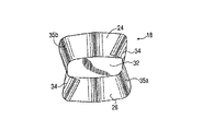
突出部18の側壁28、30には、それぞれ、外側面36及び側方面37を有する側面34及びレール35は形成されている(図2、3、4及び9)。一つの好適な構造においては、レール35は、(例えば、上記側壁の後方延長部を有する)実質的に平行な平面内で、後方に延びているが、それらは、後方に延びるのに従って、互いにそれている。具体的には、一方のレール35aは、支持面32から、収束性壁部26の後方延長部と実質的に平行である後部方向へ延びており、他方のレール35bは、支持面32から、収束性壁部24と実質的に平行な方向に後方へ延びている。このようにして、レール35a、35bは、それらは後方に延びるのに従って、略垂直方向にそれている。該レールには、好ましくは、主として容易な製造のために、線形面、略一定の奥行き及び幅が設けられている。しかしなはら、他の形態も可能である。
【0027】
好適な構造においては、一方のレールは、各収束性壁部24、26に隣接して、かつ実質的に該各収束性壁部と平行に延びている。従って、各収束性壁部24、26の外縁部は、隣接するレールの上部または底部を形成し、側方面37は、該収束性壁部の後方延長部に略平行に延びている。それにもかかわらず、変形例が可能である。例えば、上記側方面は、非線形形状、あるいは、上記収束性壁部と平行でない延長部を有してもよい。また、上記レールは、該レールは、収束性壁部24、26から離れている第2の側方面(図示せず)を有することができるように、該収束性壁部から離間していてもよい。
【0028】
各レール35の外側面36は、実質的に垂直である。好ましくは、側方面37及び側面34は、略V字状の凹部40(図3及び8)を形成するように傾斜している。従って、側方面37及び側面34は、それぞれ、先端部12に加わる垂直方向及び横方向の負荷のための主として支持面を形成するように、垂直方向に対して横方向である表面領域を呈する。収束性壁部24、26は、重い負荷の下で、あるいは、上記部分の摩耗後に、上記ソケットに接触する可能性はある第2の支持面を形成する。各側方面37は、好ましくは、そのそれぞれの側面34に対して、75°〜115°、最も好ましくは、95°の角度で設けられている。それにもかかわらず、他の角度を用いることができる。側面34は、各側壁28、30のだんだん大きくなっていく部分を形成するように、後方に延びるのに従って広はるように、略三角形状である。
【0029】
先端部12は、収束性壁部43、45及び側壁47、49によって規定される、略くさび形状の外形を有する(図1〜10)。収束性壁部43、45は、前方に突出する掘削刃51を形成するように細くなっている。後方に開口しているソケット53は、アダプタの突出部18を収容するために設けられている。
【0030】
ソケット53は、好ましくは、アダプタ突出部18に結合して収容するような形状になっている(図5、6及び8)。従って、該ソケットは、収束性面と、側面59、61と、前面63とで規定される。各側面59、61には、溝65と、内方に突出する隆起部または突起部67は形成されている。溝65は、上記アダプタ突出部上のレール35を収容するような形状になっている。すなわち、好適な構造においては、溝65は、好ましくは、対向する収束性面55、57に沿って延びるように形成されている。突起部67は、側方面37及び側面34とそれぞれ向かい合いかつそれらを支持する側方面69及び内面71を、それぞれ規定する。すなわち、側方面69及び内面71は、略垂直方向に加えられる負荷のための主として支持面を形成するのに対して、収束性面55、57は、重い負荷の下で、あるいは上記部材の摩耗後に、上記突出部に接触する可能性はある第2の支持面を形成する。前方面63は、軸方向の負荷はかかっているときに、支持面32に当接するようになっている。
【0031】
上記突出部は、上記摩耗部材に必要な金属の量を最少にするために、好ましくは、上記アダプタ上にあり、かつ上記ソケットは上記先端部にあるが、後方に延びる突出部を、上記アダプタ内に規定されたソケット内に収容されるように、上記先端部に設けることができる。また、該ソケット及び突出部の構造は、内部のレール(図示せず)を、一致する溝を該突出部(図示せず)に設けた状態で、該ソケット内に設けることができるように、逆にすることもできる。
【0032】
それるレール35及び溝65のため、先端部12は、アダプタ突出部18に嵌合したときに、ねじるか、あるいは回転しなければならない。好適な構造においては、上記先端部は、挿入されたときに、一回転の8分の1位回転する。その結果、該先端部は、どちらかといえば、直線状のレール及び溝ではなく、螺旋状のネジ山は形成されている先端部及びアダプタの場合と同じように、該アダプタの突出部に嵌合する。先端部12は、各溝65の後方部分73は、図9に示すように該レールを収容するために、対応するレール35の前方部75に隣接して位置するように、第1の指向された先端部12によって、突出部18に取付けられる。該溝は垂直方向にそれているため、上記レールの前端部と該溝の後端部との位置合わせによって、上記先端部は、その最終位置に対して回転してしまう。すなわち、該先端部は上記突出部上に滑り込むと、該先端部は、上記レールに対して十分な隙間を生じるように、長手方向の軸X周りに回転し、最終的には、レール35を各溝65内に挿入させる。図10は、レール35をソケット53の溝65内に完全に挿入した状態で、突出部18上に取付けられた先端部12を示す。
【0033】
このように、本発明は、螺旋状のネジ山を備えている(例えば、米国特許第4,353,532号明細書)が、単純かつ高価でない構造を備えている従来の摩耗アセンブリによってもたらされる一定の効果を達成する。本発明に係る上記対向するレールは、上記螺旋状のネジ山アセンブリよりも、鋳造するのが容易である。また、鋭い螺旋状の溝の代わりに、より大きなレール及び溝を使用すると、強度及び耐久性の向上によって、上記突出部における応力の立ち上がりが弱められる。
【0034】
また、本発明は、従来の螺旋状のネジ山アセンブリを上回る他の効果を実現する。本発明は、上記突出部に対して円錐形の基部を用いずに、よりほっそりした輪郭のくさび形状を用いている。すなわち、該突出部の(上面と底面との間の)高さは、円錐形基部によって制限されず、そのため、該突出部の高さは、必要に応じて調節することができる。従って、本発明の該突出部は、螺旋状のネジ山を備えた輪郭よりもよりほっそりとした輪郭を有する刃装置を形成するのに用いることができる。該よりほっそりとした輪郭の刃装置は、掘削時により良好な貫通を実現でき、形成するのにより少ない金属ですむ。
【0035】
さらに、上記ねじりの程度は、上記レールのそれを規定する角度を変えることによって変化させることができる。一般に、上記角度を大きくすればするほど、上記先端部は、取付け時及び取外し時に、より多くの量のねじりを受ける。
【0036】
この構造の場合、先端部12は、アダプタ突出部18上に安定して配置される。従来の刃と比較して、先端部12の自由端部51に対する、中心に加えられる垂直負荷P1は、反作用力A1、B1(図11)の水平成分のため、より小さい射出力を発生させる。例えば、先端部12の自由端部51に対する中心下向きの負荷P1は、突出部18の先端部及び基部において、反作用力A1、B1を発生させる。反作用力A1の垂直成分は、負荷P1に反作用力B1の垂直成分を加えたものに略等しい。しかし、上記先端部の後端部又は基端部の上向きの動きに抵抗するレール35の傾斜は、下方の収束性壁部45に対して反対方向であるため、反作用力B1の水平成分は、該先端部を射出させるよりも該アダプタに対して該先端部を押し込むように後方に向いている。そして、この保持又は固定力は、反作用力A1の水平成分により、上記射出力を少なくとも部分的にずらせる。先端部12の異なる部分へ加えられる垂直成分を有する負荷は、常に上述した固定力を発生させるわけではなく、その効果は、通常の負荷の下で発生してかなりの効果をもたらす。
【0037】
他の好適な構造においては、突出部18aの前方自由端部42は、上方及び下方の安定化平坦部(図12及び13)を有する、略矩形状の外形を有するように形成される。これらの平坦部44、46は、特に、先端部12aの前方端部に対する垂直方向の負荷に抵抗する際に、上記先端部を上記アダプタ上で安定化させるためのさらなる支持を実現するために、上記刃の長手方向軸と実質的に平行に延びている。該実質的に平行な平坦部は、抜き勾配のために、約7°まで上記長手方向軸に対して傾斜させてもよい。該平坦部は、より大きな角度で傾斜させてもよいは、それらの安定化機能は、傾斜はきつくなるにつれて減る傾向はある。先端部12aのソケット53aは、アダプタ突出部18aの平坦部44、46と係合する、一組の前方端部安定化平坦部78、79を含む。該ソケットの前方端部は、好ましくは、該突出部の前方端部と一致するように略矩形状の輪郭を呈するが、該突出部の前方端部及びソケットに対しては、矩形状以外の形状も可能である。
【0038】
好適な刃装置10aにおいては、先端部12aの自由端部に対する中心に加えられる下方への負荷P2は、射出力として作用する水平成分を概して有しない、実質的に垂直方向の反作用力A2を発生させる(図13)。上述したように、上記レールの傾斜は、上記先端部の基端において、射出力よりも保持力を伴う水平成分を発生させる。すなわち、この負荷の場合、上記支持面(例えば、上記平坦部及びレール)の全体的な効果は、上記先端部を射出させることではなく、上記アダプタに対して固定することである。
【0039】
この構造は、先端部の安定性の実質的な改善をもたらす。結果として生じる上記固定力の発生は、上記ロックピンへの負荷を少なくし、先端部の損傷のリスクを低減する。また、該結果として生じる固定力は、上記アダプタ突出部上での上記先端部の動きを減らすことにつなはり、それにより、上記刃構造の摩耗は減ることになる。さらに、上記装置は固定されていると同時に、最も支配的な、あるいは通常の垂直及び軸方向の負荷を受けているので、製造公差を緩和して、より容易かつ低コストの製造を可能にし、(負荷支持エラストマーを有する)テークアップ方式のロックピンを使用をなくすことができ、規格に対する要求も、上記刃の寿命を縮めることなく低減することができる。その代わり、該刃は、耐久性は向上する。
【0040】
従来の刃装置(図24参照)においては、上記突出部を湾曲させるそのような負荷の傾向のため、突出部2の上方及び下方の収束性壁部2a、2b(例えば、長手方向軸から最も垂直方向に離れた面)の最大の耐久性は、垂直方向の負荷の下で、高い応力レベルを有することになる。従来の刃においては、外側の収束性面は、主たる支持面を形成すると共に、最も高い応力レベルにさらされる。その結果、それらの面は、動いて上記ソケット壁部を摩擦し、重い負荷の下で、激しい摩耗を受ける。本発明においては、レール35及び側面34は、主たる支持面を形成する。該支持面は、上記刃装置の中心水平面に近いので、それらの面の摩耗は、上記外側の収束性壁部の摩耗よりも大きい湾曲性負荷に耐える上記突出部の能力により、あまり影響を受けない。より少ない摩耗によって、本発明に係る上記刃装置は、より強固でより耐久性のあるアセンブリである。その結果、より少ない金属を要し、かつ良好な貫通性を有する、本発明に従って形成されたより小さな刃装置は、従来のより大きな刃装置に取って代わることができる。また、上記最大の耐久性におけるこの摩耗の低減は、断面係数を、突出部の強度を維持する該突出部の寿命とほぼ同じのままにすることを可能にする。
【0041】
代替の実施例として、上記刃装置の取付け及び取外しに利用する回転のため、上記突出部の前方端部及び対応するソケットは、実際には、該突出部の後方端部よりも広くてもよく、すなわち、上記側壁は、前方に行くに従って、約5°までの角度でわずかにそれるように先細りにすることができる。該突出部の前方における、該突出部及びソケット幅のこの拡大は、摩耗は起きたときに、上記先端部を該突出部から意図した回転まで移動させる経路を制限することにつながる。その結果、この構造は、該先端部を動かそうとする力、および特に逆の力に対する抵抗力を増加させる。
【0042】
別の代替実施例として、上記突出部は、外側面81及び側方支持面83を含む、長手方向に延びるレール80を備えることが可能である(図14)。側方支持面83は、互いに対して、および上記刃の長手方向軸Xに対して略平行である。これらの配置においては、該レールの奥行きは、好ましくは、後方に延びるのに従って増加し、すなわち、上記突出部の収束性壁部は、たとえ、側方面83は、該刃の長手方向軸と略平行な方向に、後方へ延びていても、各レール80の上方又は下方面を形成する。それにもかかわらず、該レールは、一定の奥行きを有することができ、かつ単純に、各収束性壁部から離間することも可能である。該レールのそれはないと、上記先端部は、上記アダプタ突出部上で回転しない。取付け及び取外し時に該先端部を回転させることの恩恵の一部は、この実施形態に適用されず、該レールは、なお、上記収束性壁部の最高の耐久性において応力を低減する(従来の刃装置と比較して)安定した面を形成し、また上述したように、湾曲力に抵抗する際に、上記支持面の摩耗を低減する。略Z字状の断面を形成する、2つのみのレールの使用により、材料の量は削減されるため、上述した負荷及び摩耗の効果は改善される。また、この実施形態は、上記先端部の、取付け時のひねりが好ましくない場合、または不可能な場合にも用いることができる。一つの実施例として、該先端部は、プレートに溶接することができ、そのため上記アセンブリは、上記掘削刃に沿って上記突出するアダプタ突出部に正しく取付けることができる。
【0043】
上記全ての実施形態に関して、上記突出部及び先端部は、好ましくは、該先端部を、該突出部上にリバーシブルに取付けることができるように、長手方向軸Xの周りに回転対称になるように形成される。それにもかかわらず、本発明においては、比対称的な突出部および/または先端部を用いることが可能である。
【0044】
本発明に係る上記先端部及びアダプタは、該先端部の該アダプタからの取外しに抵抗する広範囲の異なるロックと共に用いることができる。ロック16は、先端部12の突出部18からの射出に抵抗する際に、少なくとも部分的に、せん断力の代わりに圧縮力に耐えるため(それに伴って、低減されたせん断負荷を受け)、該ロックは、実質的にせん断負荷のみを該ロックに対して加える他の従来の先端部及びアダプタと共に用いられるロックほどの強度を要しない。ロック16の配置は、好ましくは、図1、2に示すように、突出部18の一方側に沿って行われる。しかし、ロックは、(従来の刃装置のように)垂直又は水平方向の中心部分を含む他の位置に設けることができる。さらに、実質的には、固いロックピン、テークアップエラストマーを有するピン、あるいは、Jonesらに対する米国特許第5,469,648号明細書に開示されているような固いケーシングを有するロックを含むアダプタに先端部を固定するのに用いるどのような従来のロックも、本発明に関連して用いることができる。
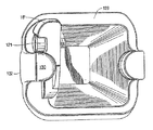
【0045】
例えば、図2は、上記突出部の側部の垂直溝89内に収容されるドライブスルー形ロックピンの形をしたロック16を示す。上記先端部は、公知であるが、該ピンの裏面に係合して該先端部の該アダプタに対して保持する、内方に延びる突起93を有する少なくとも一つの後方に延びる耳部91を備えている。好ましくは、耳部及び突起は、該先端部を180°の位置のどこでもリバーシブルに取付けることができるように、該先端部の両側(図示せず)に設けられる。上記溝及びピンは、直線状の輪郭を有して示されているが、それらは、Emrichに対する米国特許第4,965,945号明細書におけるように、湾曲させることもできる。
【0046】
好適な構造においては、上記先端部を上記アダプタに固定するために、先細りのロックピン16’が設けられている。特に図15〜18を参照すると、突出部18’は、先細りのロックピン16’を収容するために、一方の側面に沿って、先細りの垂直溝103を有する。該ロックは、その全長に沿って先細りとすることができるが、単に、その長さのかなりの部分に沿って先細りにすることを要する。好適な構造においては、前方面104は、該先細りが、該ロックの実質的に全長に沿って延びるように、該ロックの全長の後方へだんだんと弧状になっている。図15は、部分的にのみ上記突出部を通って延び、上記底部における閉じた端部105に対して先細りになっている一端は閉じた溝を示す。それにもかかわらず、上記アダプタを全体的に通って延びて開いた溝を、必要に応じて、上記先細りのピンと共に使用することができる。
【0047】
ロックピン16’は、先細りの溝103(図15〜18)内に嵌合するための対応する先細り形状を有する。ロックピン16’は、好ましくは、細い先端部106で終端する。ピン16’は、上記突出部の肩部109(例えば、溝103の前方縁部)に係合するための前方面と、耳部91’の突起93’に係合するための後方面とを有する支持部107を有する。図15〜18に示す実施形態においては、ロックピン16’は、該ロックを軸方向の力に対して強め、かつ該ロックピンの正しい挿入を保障するために、後方に延びるウェブ111を有する。しかし、該ロックピンは、均一な円形、矩形、あるいは要望に応じて他の形状を有することができる。
【0048】
突出部18’は、突起93’及び耳部91’は、該突出部の側面に沿って上記溝の位置まで通過することができるように、溝103と連通するスロット113を規定する。ピン16’は、突起93’の一部を収容するために、後方面107の後方でウェブ111の近傍に、凹部115を規定する。ロックピン16’は、鋳造等の従来のどのような方法で形成してもよい。
【0049】
ロックピン16’は、好ましくは、固定部材を用いて溝103内に保持される。図15〜18に示す実施形態においては、該固定部材は、止めネジ121である。溝103は、好ましくは、該止めネジを収容して上記ロックピンを溝103内に良好に保持するための凹み125を含むが、該凹みは、必ずしも必要ではない。ロックピン16’は、一旦、溝103内に取付けられると、止めネジ121は締められる。止めネジ121は、膨径していてもよく、あるいは、保持リングまたは、該止めネジは、上記ロックピンから外れるのを防ぐ他の手段を備えてもよい。該ロックピンは、好ましくは、該止めネジを摩耗から保護する張出しシェルフ123を含む。また、振動時のねじの緩みを阻止するために、ばね(図示せず)を上記止めネジと結合することもできる。
【0050】
ロックピン16’は、また、他の摩耗アセンブリと共に用いることもできる。例えば、図19に示すように、該ロックピンは、単純なくさび形状のソケット、耳部132、突起130を有する先端部128を保持するのに用いることができる。本発明に係る先細りのロックピンは、垂直又は水平方向の中心穴部(図示せず)を有する刃装置にも用いることができる。
【0051】
別法として、上記ピンは、上記溝から外れるのに抵抗するために、エラストマーは、裏打ちされた移動止めのような他の固定部材を設けてもよい。また、図15〜18の実施形態は、上記ロックピンを上記アダプタに結合する固定部材を示すが、該固定部材は、その代わりに、該ロックピンを上記先端部に操作可能に係合してもよい。さらに、該固定部材は、該ロックピンに取付ける必要はないは、その代わりに、別々の部材にするか、あるいは、上記アダプタ又は先端部に取付けてもよい(例えば、米国特許第4,965,945号明細書のプラグを参照)。
【0052】
代替の実施例として、ロックピン131、133(図20、図22(A),22(B)並びに図21、図23(A),22(B))は、ロックピン16’の定位置で用いることができる先細りの構造を有する。ロックピン131は、上記アダプタ突出部に規定された棚部140の下に嵌合するエラストマー138によって、一端部136において、外側に偏向している移動止め134を有する。該移動止めは、好ましくは、棚部140との強固な係合を形成するための突出した接触面136aを有する。移動止め134は、好ましくは、エラストマー138に付着しており、該エラストマーも、鋳造体135のくぼみに付着している。ロックピン133においては、移動止め141は、エラストマー145によって弓状経路143に沿って動くように偏向されている。移動止め141の自由端部147は、上記アダプタ突出部に規定された切り欠き149等に係合する。いずれの場合にも、上記アダプタ突出部は、細いスロット(図示せず)を含み、それにより、上記ロックの取外しが必要な場合に、工具を挿入して上記移動止めを該エラストマー内に押し込んで、移動止め134、141を解放することができる。
【0053】
先細りのピンの効果のうちの一つは、従来のドライブスルー形ピンよりも、取付け及び取外しが容易であるということである。該先細りの外観は、上記ロックピンが、ほぼ完全に上記溝内に挿入されるまで、上記先端部又は突出部の表面からいかなる抵抗も受けることなく、該ロックピンを挿入することができるようにする。該先細りのロックピンは、上記溝から解放されるまでに短い距離を移動するのみであるので、ハンマーでたたくよりも、プライ工具を使って取り外してもよい。該ロックピンは、一旦解放されると、手で取り外すことができる。対照的に、従来のドライブスルー形ロックピンの場合には、上記先端部と突出部との間の良好な支持接触を保障するために、該ピンの2つの支持面は、ほぼ平行になっている。従って、該ドライブスルー形ロックピンは、上記摩耗アセンブリに挿入されるに従って、あるいは該摩耗アセンブリから取り外されるにつれて、動程の全距離に沿って、かなりの抵抗を受ける。
【0054】
本発明に係る上記先細りのロックピンの他の効果は、上記固定部材が係合された状態の上記ロックを取り外すのに必要な力は、従来のドライブスルー形ロックピンを取り外すのに要する力よりも大きいということである。上記先細りのロックピンは、上記溝は先細りになっており、または終端しており、また、上記止めネジ等の上記ロック部材は、該ロックピンの上記溝から上方への動きを防ぐため、下方への動きが抑止される。従って、該ロックピンは、取付け後の上記先細りのロックピンの取外しを防ぐために、しっかりした嵌合ではなく、機械的な接触を基にしている。
【0055】
上述の議論は、本発明の好適な実施形態に関係している。様々な他の実施形態、多くの変形例及び代替例を、特許請求の範囲に記載したような本発明の主旨及び広範囲の態様から逸脱することなく、実施することが可能である。
【図面の簡単な説明】
【0056】
【図1】本発明による掘削刃装置の斜視図である。
【図2】刃装置の分解斜視図である。
【図3】刃装置のためのアダプタの正面図である。
【図4】図の平面と平行な前方支持面のみ有するアダプタ突出部の正面図である。
【図5】刃装置用の先端部の後部斜視図である。
【図6】先端部の後部正面図である。
【図7】刃装置の部分平面図である。
【図8】図7の線8−8に沿った、刃装置の断面図である。
【図9】アダプタの突出部に取り付けるために配置された先端部の側面図である。
【図10】アダプタに取り付けられた先端部の部分断面図である。
【図11】図1及び2に係る刃装置のベクトル力図である。
【図12】本発明に係る刃装置の代替の実施形態の斜視図である。
【図13】図12に係る刃装置のベクトル力図である。
【図14】本発明に係る刃装置の他の代替実施形態のアダプタの側面図である。
【図15】代替のロックを有する、本発明に係る第2の刃装置の分解斜視図である。
【図16】代替のロックを、その固定位置に入れた状態の第2の刃装置の部分側面図である。
【図17】図16の線17−17に沿った部分断面図である。
【図18】代替のロックの斜視図である。
【図19】代替の刃装置の先端部に係合した、代替のロックの後方図である。
【図20】刃装置に挿入された、別の代替のロックの斜視図である。
【図21】刃装置に挿入された、別の代替のロックの側面図である。
【図22】(A)は、図20に示すロックの斜視図、また(B)は、図20に示すロックの側面図である。
【図23】(A)は、図21に示すロックの斜視図、また(B)は、点線で示すエラストマー及び移動止めの基部を有する、図21に示すロックの斜視図である。
【図24】従来の刃装置のベクトル力図である。
【図25】他の公知の刃装置のベクトル力図である。【Technical field】
[0001]
The present invention relates to wear assemblies and, more particularly, to wear assemblies for use with mining equipment, excavating machines and earthworking machines. The design of the present invention is particularly well suited for excavating blades, but may be used to support other wear members.
[Background]
[0002]
During mining and construction, wear members are generally provided along the excavating blades of the machine to protect buckets and / or to engage and / or grind the soil to be collected. Therefore, the wear member is in a severe wear state and is subject to considerable wear. Therefore, the worn part must be replaced regularly.
[0003]
In order to minimize material loss due to replacement of worn parts, the wear assembly is typically manufactured as two or more separable components including an adapter and a wear member. The adapter is attached to the drilling blade by casting along the blade of the drilling rig so as to present a forward projecting protrusion that supports welding, mechanical attachment, or the wear member. The wear member includes a socket that is accommodated by being covered with the protruding portion, and a front action end portion. At the tip, the working end is generally a narrowed excavating blade. The wear member substantially covers the adapter protrusion, thereby attempting to protect the protrusion from wear. For example, due to various factors, approximately 5 to 20 tips can be continuously attached to a single adapter before the adapter wears out and requires replacement. In order to accommodate on-site replacement of the wear member, the wear member is typically secured to the adapter protrusion by a removable lock (eg, a lock pin).
[0004]
Wear assemblies used in mining, drilling and construction work, and in particular drilling blade equipment, are subject to large and changing forces applied in all directions. As a result, the tip and other wear members must be securely fastened to the adapter to withstand impacts, vibrations, and other types of forces as well as axial, vertical, reverse and lateral loads. The vertical load was particularly troublesome in that a large moment force was generated that would attempt to “rotate” the wear member forward on the adapter, which could lead to injection of the wear member. The wall of the adapter protrusion forms a support for the wear member, but the lock often holds the tip and resists loads, particularly moments and reverse forces. It also plays a big role.
[0005]
In the conventional blade device 1 (FIG. 24), the
[0006]
In this example center lower load P, the vertical component of the reaction force A is generally equal to the lower load P plus the vertical component of the reaction force B. However, because of the converging wall of the protrusion, the horizontal component of each of the reaction forces A and B is the forward direction in which the tip is to be propelled. To the extent that their forces are not directly resisted by the protrusion and socket profile and friction, they are resisted as a shear load by the lock pin. Repeated application of a large shear load can cause unacceptable high stress on the lock pin and can lead to breakage.
[0007]
Further, in such a conventional blade, the lock pin is usually driven into a fixed position, and is caused by the frictional force initially applied by the arrangement of the hole in the tip portion with respect to the hole in the adapter protrusion. Hold tight. However, wear of the tip and adapter tends to loosen the connection, increasing the risk of removing the lock pin. Thus, the lock pin is initially set very tightly within the defined opening to delay the time if excessive loosening occurs. Therefore, the lock pin must be driven into the opening and driven out of the opening by repeated smashing of a large hammer. This is a cumbersome and time consuming task, especially for large sized blades.
[0008]
As wear begins to occur, a take-up elastomer may be placed in front of the lock pin as an effort to maintain a tight fit between the tip and the adapter. The elastomer functions to draw the tip onto the adapter and reduces the ability of the lock to resist applied moment and reverse forces. Those loads tend to generate more stress on the elastomer than can be withstood. As a result, during use, excessive use of the elastomer can lead to premature failure and damage to the lock pin, thereby leading to loss of the tip.
[0009]
Tip failure due to pin failure, looseness or elastomer problems not only leads to premature failure of the tip and wear of the adapter protrusion, but can also handle the drilled raw material, especially in mining operations. Causes potential damage to the machine. Also, since the adapter is often welded in place, adapter replacement generally results in significant work downtime for the excavating machine.
[0010]
Various different tip and protrusion designs have been developed to increase the stability of the connection between the tip and adapter, reduce the force to inject the tip, and reduce the load on the lock. ing.
[0011]
In one
[0012]
In another design, such as that disclosed in US Pat. No. 5,709,043 to Jones et al., The protrusion and socket are each substantially parallel to the longitudinal axis of the blade. And a front rectangular part and a rear support surface. In this structure, the effect of combining the front stabilizing flat part and the parallel support surface generates reaction force that is only in the substantially vertical direction at the tip and base of the protrusion. Such vertical reaction forces generally do not generate a substantial horizontal component. Therefore, this structure greatly reduces the force of pushing the tip from the adapter. Such stabilization of the tip also reduces displacement and movement of the tip on the adapter due to reduced wear. Nevertheless, other factors (e.g., impact etc.) and reverse forces can still apply large shear forces to the lock.
[0013]
In other designs, such as those disclosed in U.S. Pat. No. 4,353,532 to Hahn et al., The tip and adapter are each when the tip is attached to the adapter protrusion. , With helical turns or threads to rotate about its longitudinal axis. Due to the thread, the tip rotates about the longitudinal axis of the blade and generally presses the lock against the adapter protrusion when a radial force is applied. The lock is less prone to failure when subjected to that kind of compressive force, in contrast to the large shear forces applied to conventional blades. This structure provides great strength and retention, while the protrusions and sockets are complex and expensive to manufacture.
DISCLOSURE OF THE INVENTION
[Problems to be solved by the invention]
[0014]
The present invention relates to a wear assembly that can provide a stable bond that can withstand heavy loads without overstressing the lock.
[Means for Solving the Problems]
[0015]
In one aspect of the invention, the wear assembly includes a support surface configured to be fixed relative to the adapter by applying a constant load to the wear member. In one preferred construction, the support surface is a horizontal component of the reaction force generated to resist, e.g., a vertical load applied to the center, against the adapter protrusion that makes the wear member more tight. It is oriented so that it can be pushed backwards.
[0016]
In another aspect of the invention, the wear member rotates on and away from the adapter about its longitudinal axis in order to better resist radiation. In the preferred embodiment, this rotation is achieved by substantially linear rails and grooves that are easy and inexpensive to manufacture. Their complementary rails and grooves allow the assembly to have a more elongated profile rather than having a helical thread for good penetration and less metal usage in drilling applications. To do. Such grooves and rails also avoid the occurrence of high stress rises due to the use of relatively square grooves used to form helical threads.
[0017]
According to another aspect of the invention, the protrusion of the adapter or the socket of the wear member is provided with a rail that deviates as it extends rearward. Thus, the complementary protrusion or socket has a groove that fits and accommodates the rail. In a preferred embodiment, the vertical deflection of the rail prevents axial attachment of the wear member, and when the wear member moves to and away from the protrusion of the adapter, It is necessary to twist the wear member.
[0018]
In another aspect of the invention, the adapter includes two support surfaces disposed on opposite sides of the longitudinal axis and facing in opposite directions. In a preferred embodiment, these support surfaces reduce wear for maximum durability of the top and bottom of the protrusion. The support surface is preferably formed as a part of the rail on the adapter so as to form a substantially Z-shaped cross section.
[0019]
In another aspect of the invention, the adapter protrusion and the wear member socket are wider as they extend forward. In a preferred embodiment, the adapter and socket have complementary rails and grooves that deflect during installation to require twisting of the wear member. This structure accommodates the forward projecting portion into the socket and forms a sufficient gap to withstand the wear member injection well.
[0020]
In another aspect of the invention, the lock is tapered to fit into a complementary groove to reduce frictional forces and facilitate insertion and removal of the lock. In this configuration, the full length of the lock does not slide frictionally through the aligned opening, but engages the side of the groove at or near the engagement position. When inserting or removing the lock, hitting the lock is avoided. In a preferred embodiment, the lock has a locking member for securing the lock in the groove to prevent unwanted damage or injection.
[0021]
The above and other objects, features and advantages of the present invention will be more readily understood when the following description of the invention is considered in conjunction with the accompanying drawings.
BEST MODE FOR CARRYING OUT THE INVENTION
[0022]
The present invention focuses on a wear member that protects the wear surface. In particular, the wear assembly is particularly suitable for use in excavation, mining, construction work and the like. The wear assembly is suitable for use in constructing a drilling blade device, but can also be used to form other wear members.
[0023]
For illustration purposes, this application describes the inventive structure as a drilling blade device. Other wear member (e.g., shroud) products may use the same protrusion and socket structure, but may have different working and mounting ends. The terms upper, lower, vertical, etc. will be understood when referring to the blade device as used herein for purposes of illustration only and adapted to FIG. The use of these terms is not an indication that these specific orientations are required for the wear assembly. The wear assembly can be oriented differently than shown in FIG.
[0024]
In a preferred structure, the blade device 10 includes a
[0025]
The protruding portion has a substantially wedge shape, and is formed by the converging
[0026]
[0027]
In a preferred construction, one rail extends adjacent to each converging
[0028]
The
[0029]
The
[0030]
The
[0031]
In order to minimize the amount of metal required for the wear member, the protrusion is preferably on the adapter, and the socket is at the tip, but the protrusion extending rearward is connected to the adapter. The tip can be provided so as to be accommodated in a socket defined therein. In addition, the structure of the socket and the protruding portion is such that an inner rail (not shown) can be provided in the socket with a matching groove provided in the protruding portion (not shown). The reverse is also possible.
[0032]
Because of the
[0033]
Thus, the present invention results from a conventional wear assembly with a helical thread (eg, US Pat. No. 4,353,532) but with a simple and inexpensive structure. Achieve a certain effect. The opposing rails according to the present invention are easier to cast than the helical thread assembly. Also, if larger rails and grooves are used instead of sharp spiral grooves, the rise in stress at the protrusions is weakened due to improved strength and durability.
[0034]
The present invention also realizes other advantages over conventional helical thread assemblies. The present invention uses a wedge shape with a slimmer profile without using a conical base for the protrusion. That is, the height of the protrusion (between the top and bottom surfaces) is not limited by the conical base, so the height of the protrusion can be adjusted as needed. Thus, the protrusions of the present invention can be used to form a blade device having a slimmer profile than a profile with a helical thread. The slender profile blade device can achieve better penetration during excavation and requires less metal to form.
[0035]
Furthermore, the degree of torsion can be varied by changing the angle defining that of the rail. In general, the greater the angle, the greater the amount of torsion of the tip during attachment and removal.
[0036]
In the case of this structure, the
[0037]
In another preferred construction, the front free end 42 of the
[0038]
In the preferred blade device 10a, the downward load P2 applied to the center of the
[0039]
This structure provides a substantial improvement in tip stability. The resulting generation of the fixing force reduces the load on the lock pin and reduces the risk of tip damage. The resulting securing force also reduces the movement of the tip on the adapter protrusion, thereby reducing wear of the blade structure. In addition, the device is fixed and at the same time is subjected to the most dominant or normal vertical and axial loads, thus reducing manufacturing tolerances and enabling easier and lower cost manufacturing, The use of a take-up lock pin (having a load-supporting elastomer) can be eliminated, and the requirements for standards can also be reduced without reducing the life of the blade. Instead, the blade has improved durability.
[0040]
In the conventional blade device (see FIG. 24), the converging wall portions 2a and 2b above and below the projecting portion 2 (for example, the most from the longitudinal axis) due to the tendency of the load to bend the projecting portion. Maximum durability (vertically spaced surfaces) will have high stress levels under vertical loads. In conventional blades, the outer convergent surface forms the main support surface and is exposed to the highest stress levels. As a result, these surfaces move and rub against the socket wall and are subject to severe wear under heavy loads. In the present invention, the
[0041]
As an alternative embodiment, the front end of the protrusion and the corresponding socket may actually be wider than the rear end of the protrusion due to the rotation used to attach and remove the blade device. That is, the side wall can be tapered to slightly deviate by an angle of up to about 5 ° as it goes forward. This enlargement of the protrusion and socket width in front of the protrusion leads to limiting the path through which the tip moves from the protrusion to the intended rotation when wear occurs. As a result, this structure increases the force trying to move the tip and in particular the resistance to the opposite force.
[0042]
As another alternative, the protrusion may include a
[0043]
For all of the above embodiments, the protrusion and tip are preferably rotationally symmetric about the longitudinal axis X so that the tip can be reversibly mounted on the protrusion. It is formed. Nevertheless, it is possible in the present invention to use specific symmetrical protrusions and / or tips.
[0044]
The tip and adapter according to the present invention can be used with a wide range of different locks that resist removal of the tip from the adapter. Because the
[0045]
For example, FIG. 2 shows a
[0046]
In a preferred structure, a tapered lock pin 16 'is provided to secure the tip to the adapter. With particular reference to FIGS. 15-18, the
[0047]
The lock pin 16 'has a corresponding tapered shape for fitting into the tapered groove 103 (FIGS. 15-18). The
[0048]
The protruding
[0049]
The lock pin 16 'is preferably held in the
[0050]
Lock pin 16 'can also be used with other wear assemblies. For example, as shown in FIG. 19, the lock pin can be used to hold a
[0051]
Alternatively, the elastomer may be provided with other securing members, such as a lined detent, in order to resist the pin from coming out of the groove. 15 to 18 show a fixing member that couples the lock pin to the adapter. The fixing member, instead, operably engages the lock pin with the tip. Also good. Further, the securing member need not be attached to the locking pin, but instead may be a separate member or attached to the adapter or tip (eg, US Pat. No. 4,965,965). (See the 945 plug).
[0052]
As an alternative embodiment, lock pins 131, 133 (FIGS. 20, 22A, 22B and FIGS. 21, 23A, 22B) are in place of
[0053]
One of the effects of a tapered pin is that it is easier to install and remove than a conventional drive-through pin. The tapered appearance allows the lock pin to be inserted without receiving any resistance from the surface of the tip or protrusion until the lock pin is almost completely inserted into the groove. To do. The taper lock pin only moves a short distance before it is released from the groove, so it may be removed using a ply tool rather than hitting with a hammer. Once released, the lock pin can be removed by hand. In contrast, in the case of a conventional drive-through lock pin, the two support surfaces of the pin are substantially parallel to ensure good support contact between the tip and the protrusion. Yes. Thus, the drive-through lock pin is subject to significant resistance along the entire distance of travel as it is inserted into or removed from the wear assembly.
[0054]
Another effect of the tapered lock pin according to the present invention is that the force required to remove the lock with the fixing member engaged is greater than the force required to remove the conventional drive-through lock pin. Is also big. The tapered lock pin has the groove tapered or terminated, and the lock member such as the set screw is positioned below to prevent the lock pin from moving upward from the groove. Movement to is suppressed. Therefore, the lock pin is based on mechanical contact rather than a tight fit to prevent removal of the tapered lock pin after installation.
[0055]
The above discussion relates to preferred embodiments of the present invention. Various other embodiments, many variations and alternatives may be practiced without departing from the spirit and broad scope of the invention as set forth in the claims.
[Brief description of the drawings]
[0056]
FIG. 1 is a perspective view of an excavating blade device according to the present invention.
FIG. 2 is an exploded perspective view of the blade device.
FIG. 3 is a front view of an adapter for a blade device.
FIG. 4 is a front view of an adapter protrusion having only a front support surface parallel to the plane of the drawing.
FIG. 5 is a rear perspective view of a tip portion for a blade device.
FIG. 6 is a rear front view of the tip portion.
FIG. 7 is a partial plan view of the blade device.
8 is a cross-sectional view of the blade device taken along line 8-8 of FIG.
FIG. 9 is a side view of the distal end disposed for attachment to the protrusion of the adapter.
FIG. 10 is a partial cross-sectional view of a distal end portion attached to an adapter.
11 is a vector force diagram of the blade device according to FIGS. 1 and 2. FIG.
FIG. 12 is a perspective view of an alternative embodiment of a blade device according to the present invention.
13 is a vector force diagram of the blade device according to FIG. 12;
FIG. 14 is a side view of an adapter of another alternative embodiment of a blade device according to the present invention.
FIG. 15 is an exploded perspective view of a second blade device according to the present invention having an alternative lock.
FIG. 16 is a partial side view of the second blade device with an alternative lock in its locked position.
17 is a partial cross-sectional view taken along line 17-17 of FIG.
FIG. 18 is a perspective view of an alternative lock.
FIG. 19 is a rear view of an alternative lock engaged with the tip of an alternative blade device.
FIG. 20 is a perspective view of another alternative lock inserted into the blade device.
FIG. 21 is a side view of another alternative lock inserted into the blade device.
22A is a perspective view of the lock shown in FIG. 20, and FIG. 22B is a side view of the lock shown in FIG.
23A is a perspective view of the lock shown in FIG. 21, and FIG. 23B is a perspective view of the lock shown in FIG. 21 having an elastomer and a detent base shown by dotted lines.
FIG. 24 is a vector force diagram of a conventional blade device.
FIG. 25 is a vector force diagram of another known blade device.
Claims (128)
長手方向軸を規定し、かつ前方作用端部と、前記突出部を収容するための後方に開口したソケットとを具備し、該ソケットは、各々が、前記長手方向軸に対して傾斜して延びている互いに対向する収束性面と側面とによって規定され、各側面は、前記アダプタに係合するために、前記収束性面の間に側方支持面を含み、各側方支持面は、前記収束性面のうちの異なる一つと対向し、かつ前記長手方向軸に対して、前記側方支持面は、面する前記収束性面と略同じ傾斜方向に延びており、また
前記摩耗部材を前記アダプタに対して保持するロックを具備する摩耗アセンブリ。An adapter having a rear mounting end for securing the wear assembly to the wear surface and a forwardly extending protrusion;
Defining a longitudinal axis and comprising a forward working end and a rearwardly open socket for receiving the protrusion, each socket extending obliquely with respect to the longitudinal axis. Each side surface includes a lateral support surface between the convergent surfaces for engaging the adapter, and each lateral support surface includes Opposite one of the converging surfaces, and with respect to the longitudinal axis, the lateral support surface extends in substantially the same inclined direction as the converging surface facing, and the wear member is A wear assembly having a lock that holds against the adapter.
長手方向軸を規定し、細い前方作用端部へ延びている一組の収束性壁部と、一組の側壁と、各々が、前記レールを収容するために、ソケットの対向する面上に設けられた一組の溝を有する後方に開口した該ソケットとを含む摩耗部材であって、各溝は、前記長手方向軸と位置合わせされた平面からそれており、かつ前記細い前方作用端部に沿って延びている摩耗部材と、
前記摩耗部材を前記アダプタに固定するロックとを具備する摩耗アセンブリ。An adapter having a rear mounting end for securing the wear assembly to the wear surface and a forwardly extending protrusion having a set of rails;
A set of converging walls defining a longitudinal axis and extending to a narrow forward working end, and a set of side walls, each provided on opposite surfaces of the socket to accommodate the rail A rear-opening socket having a set of grooves formed on the narrow front working end, each groove deviating from a plane aligned with the longitudinal axis. A wear member extending along;
A wear assembly comprising a lock for securing the wear member to the adapter.
一組の収束性壁部及び一組の側壁を有する摩耗部材と、
前記摩耗部材を前記アダプタに対して保持するロックとを備え、
前記アダプタ及び摩耗部材のうちの一方は、突出部を含み、該突出部は、一組の収束性壁部及び一組の側壁を有し、前記アダプタ及び摩耗部材のうちの他方は、前記突出部を収容するソケットを含み、
前記突出部及びソケットのうちの一方は、前記側壁の各々に沿って略長手方向のレールを含み、該レールのうちの一方は、前記収束性壁部の各々と略同じ方向に傾斜しており、
前記突出部及びソケットのうちの他方は、前記レールを収容する一組の溝を含む摩耗アセンブリ。An adapter having a rear portion adapted to be secured to the wear surface;
A wear member having a set of converging walls and a set of side walls;
A lock that holds the wear member against the adapter;
One of the adapter and the wear member includes a protrusion, the protrusion having a set of converging wall portions and a set of side walls, and the other of the adapter and the wear member is the protrusion. Including a socket to accommodate the part,
One of the protrusion and socket includes a substantially longitudinal rail along each of the side walls, and one of the rails is inclined in substantially the same direction as each of the converging wall portions. ,
The wear assembly, wherein the other of the protrusion and socket includes a set of grooves for receiving the rails.
前方作用端部と、後方に開口したソケットとを含む摩耗部材であって、該ソケットは、その長さの実質的に一部にわたって、略Z字状の断面形状を有する摩耗部材と、
前記アダプタに前記摩耗部材を固定するロックとを具備する摩耗アセンブリ。An adapter having a rear attachment adapted to secure the wear assembly to the wear surface and a forwardly extending protrusion;
A wear member including a front working end and a socket open to the rear, the socket having a substantially Z-shaped cross-sectional shape over substantially a portion of its length;
A wear assembly comprising a lock for securing the wear member to the adapter.
長手方向軸を規定し、かつ前方作用端部と、前記突出部を収容するための後方に開口したソケットとを含む摩耗部材と、
前記摩耗部材を前記アダプタに対して保持するロックとを具備し、
前記突出部及びソケットは、複数の協働線形レールと、設置時及び前記突出部から取り外すときに、略前記長手方向軸周りに回転するために、前記摩耗部材を要する溝とを含む摩耗アセンブリ。An adapter having a rear mounting end for securing the wear assembly to the wear surface and a forwardly extending protrusion;
A wear member that defines a longitudinal axis and includes a forward working end and a rearwardly open socket for receiving the protrusion;
A lock for holding the wear member with respect to the adapter;
The wear assembly includes a plurality of cooperating linear rails and a groove that requires the wear member to rotate about the longitudinal axis when installed and removed from the protrusion.
前方作用端部と、側面及び収束性面によって規定された後方に開口したソケットとを含む摩耗部材であって、該ソケットは、前記レールを収容するために、前記側面のそれぞれの上に溝を有し、該溝は、それぞれ、該溝の一方の面上の前記収束性面と、該溝の他方の面上の側方支持面とのうちの一方によって規定されており、該側方支持面は、反対側の方向に面している摩耗部材と、
前記摩耗部材を前記アダプタに保持するロックとを具備する摩耗アセンブリ。An adapter having a rear mounting end for securing the wear assembly to the wear surface and a forwardly extending projection having a rail;
A wear member comprising a forward working end and a rearwardly open socket defined by a side surface and a converging surface, the socket having a groove on each of the side surfaces for receiving the rail. Each of the grooves is defined by one of the converging surface on one side of the groove and a side support surface on the other side of the groove, the side support The surface is a wear member facing in the opposite direction;
A wear assembly comprising a lock for holding the wear member to the adapter.
前方作用端部と、側面及び収束性面によって規定された後方に開口したソケットとを含み、前記側方支持面は、前記前方作用端部に向かって延びるのに従ってそれている摩耗部材と、
前記摩耗部材を前記アダプタに保持するロックとを具備する摩耗アセンブリ。An adapter having a rear mounting end for securing the wear assembly to the wear surface and a forwardly extending protrusion;
A wear member including a front working end and a rearwardly open socket defined by a side surface and a converging surface, the side support surface being deflected as it extends toward the front working end;
A wear assembly comprising a lock for holding the wear member to the adapter.
細長い本体の少なくとも実質的な長さに沿って、一端に向かって傾斜している該細長い本体と、
前記摩耗アセンブリに前記ロックを固定するために、前記本体から横方向に延びている可動ロック部材とを具備するロック。A wear assembly lock for an excavator having an adapter and a wear member,
The elongate body inclined toward one end along at least a substantial length of the elongate body;
A lock comprising a movable locking member extending laterally from the body for securing the lock to the wear assembly.
Applications Claiming Priority (2)
| Application Number | Priority Date | Filing Date | Title |
|---|---|---|---|
| US09/899,535 US6735890B2 (en) | 2001-07-06 | 2001-07-06 | Wear assembly |
| PCT/US2002/019795 WO2003004783A2 (en) | 2001-07-06 | 2002-07-03 | Wear assembly |
Related Child Applications (1)
| Application Number | Title | Priority Date | Filing Date |
|---|---|---|---|
| JP2008231644A Division JP4791516B2 (en) | 2001-07-06 | 2008-09-10 | Wear assembly and wear member |
Publications (3)
| Publication Number | Publication Date |
|---|---|
| JP2004522028A true JP2004522028A (en) | 2004-07-22 |
| JP2004522028A5 JP2004522028A5 (en) | 2007-09-13 |
| JP4295085B2 JP4295085B2 (en) | 2009-07-15 |
Family
ID=25411164
Family Applications (2)
| Application Number | Title | Priority Date | Filing Date |
|---|---|---|---|
| JP2003510530A Expired - Lifetime JP4295085B2 (en) | 2001-07-06 | 2002-07-03 | Wear assembly |
| JP2008231644A Expired - Lifetime JP4791516B2 (en) | 2001-07-06 | 2008-09-10 | Wear assembly and wear member |
Family Applications After (1)
| Application Number | Title | Priority Date | Filing Date |
|---|---|---|---|
| JP2008231644A Expired - Lifetime JP4791516B2 (en) | 2001-07-06 | 2008-09-10 | Wear assembly and wear member |
Country Status (21)
| Country | Link |
|---|---|
| US (3) | US6735890B2 (en) |
| EP (3) | EP1637660B1 (en) |
| JP (2) | JP4295085B2 (en) |
| KR (1) | KR101024445B1 (en) |
| CN (3) | CN1274917C (en) |
| AR (3) | AR034737A1 (en) |
| AT (3) | ATE462047T1 (en) |
| AU (2) | AU2002320131B2 (en) |
| BR (3) | BR0210755B1 (en) |
| CA (1) | CA2451309C (en) |
| DE (4) | DE20221725U1 (en) |
| DK (2) | DK1637661T3 (en) |
| ES (3) | ES2287298T3 (en) |
| MX (2) | MX343761B (en) |
| MY (3) | MY143623A (en) |
| NO (1) | NO336703B1 (en) |
| NZ (2) | NZ545677A (en) |
| PE (1) | PE20030264A1 (en) |
| PT (2) | PT1637661E (en) |
| WO (1) | WO2003004783A2 (en) |
| ZA (1) | ZA200400018B (en) |
Cited By (3)
| Publication number | Priority date | Publication date | Assignee | Title |
|---|---|---|---|---|
| JP2009526935A (en) * | 2006-02-17 | 2009-07-23 | エスコ・コーポレイション | Wear assembly |
| JP2010526953A (en) * | 2007-05-10 | 2010-08-05 | エスコ・コーポレイション | Wear assembly for drilling equipment |
| JP2012517539A (en) * | 2009-02-06 | 2012-08-02 | メタロヘニア,エセ.ア. | Connection system for excavators and similar machinery and components thereof for connecting mounting elements to adapters |
Families Citing this family (124)
| Publication number | Priority date | Publication date | Assignee | Title |
|---|---|---|---|---|
| US20040060207A1 (en) * | 2002-09-27 | 2004-04-01 | Livesay Richard E. | Mechanically attached tip assembly |
| AR046804A1 (en) * | 2003-04-30 | 2005-12-28 | Esco Corp | ASSEMBLY COUPLING ASSEMBLY FOR EXCAVATOR SHOVEL |
| USD552631S1 (en) | 2004-02-10 | 2007-10-09 | Italricambi Srl | Tooth assembly for buckets |
| ITUD20040021A1 (en) * | 2004-02-10 | 2004-05-10 | Italricambi Srl | TOOTH FOR EXCAVATOR BUCKETS OR SIMILAR |
| USD546350S1 (en) * | 2004-02-10 | 2007-07-10 | Italricambi Srl | Tooth assembly for buckets |
| USD552632S1 (en) | 2004-02-10 | 2007-10-09 | Italricambi Srl | Tooth assembly for buckets |
| US20060010725A1 (en) * | 2004-07-14 | 2006-01-19 | Jackson Michael J | Excavating tooth and adapter |
| CA2576218A1 (en) * | 2004-08-02 | 2006-02-09 | Wundowie Foundry Pty Ltd. | Tooth and adaptor assembly |
| USD560232S1 (en) * | 2005-05-30 | 2008-01-22 | Italricambi Spa | Tooth assembly for buckets |
| AU2005203574C1 (en) * | 2005-08-10 | 2013-11-07 | Cutting Edges Equipment Parts Pty Ltd | Adaptor, intermediate adaptor and tooth assembly or construction |
| UA94416C2 (en) * | 2005-08-30 | 2011-05-10 | Еско Корпорейшн | Wear assembly for excavating machines |
| MY149408A (en) * | 2005-08-30 | 2013-08-30 | Esco Corp | Wear assembly for excavating machines |
| CA2523513A1 (en) * | 2005-10-14 | 2007-04-14 | Amsco Cast Products (Canada) Inc. | Tooth and adaptor assembly for a dipper bucket |
| AU2012200752C1 (en) * | 2006-02-17 | 2016-10-06 | Esco Group Llc | Wear Assembly |
| PL2902552T3 (en) * | 2006-03-30 | 2021-01-11 | Esco Group Llc | Wear member for excavating equipment |
| MY142299A (en) * | 2006-04-24 | 2010-11-15 | Esco Corp | Wear assembly |
| CA2652603C (en) * | 2006-06-16 | 2013-01-15 | Esco Corporation | Lock for securing wear parts to earth-working equipment |
| US7658024B2 (en) * | 2006-07-06 | 2010-02-09 | H&L Tooth Company | Universal digging tooth attachment apparatus |
| ES2750372T3 (en) * | 2006-08-16 | 2020-03-25 | Caterpillar Inc | Earthmoving Tool Set |
| CA2719712C (en) | 2007-03-29 | 2013-11-19 | Cqms Pty Ltd | Mounting of wear members |
| WO2008119103A1 (en) | 2007-04-03 | 2008-10-09 | Cqms Pty Ltd | A mounting pin assembly for an excavator wear member |
| US8061064B2 (en) | 2007-05-10 | 2011-11-22 | Esco Corporation | Wear assembly for excavating equipment |
| CA2597277C (en) * | 2007-08-14 | 2011-11-08 | Neil Douglas Bentley | Retainer pin and tooth for tooth and adaptor assembly |
| CA2612341A1 (en) * | 2007-11-27 | 2009-05-27 | Black Cat Blades Ltd. | Ground engaging tool blade |
| USD602505S1 (en) * | 2007-12-13 | 2009-10-20 | Hensley Industries, Inc. | Ground engaging wear member |
| NO334868B1 (en) | 2008-04-10 | 2014-06-23 | Komatsu Kvx Llc | Drawer wear unit comprising a wear part and an adapter |
| US20110058894A1 (en) * | 2008-04-18 | 2011-03-10 | Cqms Pty Ltd | A lock assembly for an excavator wear member |
| AU320746S (en) * | 2008-04-28 | 2008-08-12 | Cqms Pty Ltd | A locking pin for an excavator wear assembly |
| US20090277050A1 (en) * | 2008-05-06 | 2009-11-12 | Esco Corporation | Wear Assembly For Excavating Equipment |
| GB2461910B (en) * | 2008-07-17 | 2012-07-18 | Bamford Excavators Ltd | Method of operating an apparatus |
| PL3184701T3 (en) * | 2009-03-23 | 2023-06-19 | Black Cat Wear Parts Ltd. | Fully stabilized excavator tooth attachment |
| US7980011B2 (en) * | 2009-03-23 | 2011-07-19 | Black Cat Blades Ltd. | Fully stabilized excavator tooth attachment |
| US9359744B2 (en) * | 2009-08-05 | 2016-06-07 | H&L Tooth Company | Multipiece wear assembly |
| EP2494113B1 (en) * | 2009-10-30 | 2019-03-06 | ESCO Group LLC | Wear assembly for excavating equipment |
| USRE45710E1 (en) * | 2009-12-11 | 2015-10-06 | CQMS Pty Limited | Locking pin assembly for an excavator wear member |
| WO2011069212A1 (en) * | 2009-12-11 | 2011-06-16 | Cqms Pty Ltd | A wear member assembly |
| USD634605S1 (en) * | 2010-05-24 | 2011-03-22 | Cqms Pty Ltd | Locking pin assembly for an excavator wear member |
| PE20130327A1 (en) | 2009-12-11 | 2013-04-03 | Cqms Pty Ltd | FIXING PIECE FOR AN EXCAVATOR CONSUMABLE |
| BR112012015521A2 (en) * | 2009-12-24 | 2018-05-29 | Cqms Pty Ltd | "wear set for an excavator bucket" |
| US9185335B2 (en) | 2009-12-28 | 2015-11-10 | Thomson Licensing | Method and device for reception of video contents and services broadcast with prior transmission of data |
| JOP20200150A1 (en) | 2011-04-06 | 2017-06-16 | Esco Group Llc | Hardfaced wearpart using brazing and associated method and assembly for manufacturing |
| US9757730B2 (en) * | 2011-07-06 | 2017-09-12 | Joy Mm Delaware, Inc. | Pick retainer |
| US8890672B2 (en) | 2011-08-29 | 2014-11-18 | Harnischfeger Technologies, Inc. | Metal tooth detection and locating |
| AU2012307065B2 (en) | 2011-09-08 | 2017-10-26 | Cqms Pty Ltd | A lock assembly for an excavator wear member |
| CN102443954B (en) * | 2011-09-27 | 2014-07-02 | 东华大学 | Electromagnetic shielding weft knitted fabric formed of carbon filament core-spun yarns and purposes thereof |
| USD706840S1 (en) | 2011-10-07 | 2014-06-10 | Caterpillar, Inc. | Tip for a ground engaging machine implement |
| USD706312S1 (en) | 2011-10-07 | 2014-06-03 | Caterpiller, Inc. | Tip for a ground engaging machine implement |
| USD707264S1 (en) | 2011-10-07 | 2014-06-17 | Caterpillar Inc. | Adapter for a ground engaging machine implement |
| US9062436B2 (en) | 2011-10-07 | 2015-06-23 | Caterpillar Inc. | Implement tooth assembly with tip and adapter |
| US8943717B2 (en) | 2011-10-08 | 2015-02-03 | Caterpillar Inc. | Implement tooth assembly with tip and adapter |
| USD706307S1 (en) | 2011-10-07 | 2014-06-03 | Caterpillar, Inc. | Adapter for a ground engaging machine implement |
| US9057177B2 (en) | 2011-10-08 | 2015-06-16 | Caterpillar Inc. | Implement tooth assembly with tip and adapter |
| US8943716B2 (en) | 2011-10-10 | 2015-02-03 | Caterpillar Inc. | Implement tooth assembly with tip and adapter |
| EP2581506A1 (en) * | 2011-10-14 | 2013-04-17 | Caterpillar Work Tools B. V. | Wear pack for a demolition tool |
| MY181319A (en) | 2011-11-23 | 2020-12-21 | Esco Group Llc | Wear assembly |
| WO2013082678A1 (en) | 2011-12-08 | 2013-06-13 | Cqms Pty Ltd | An excavator wear assembly |
| US8959807B2 (en) * | 2011-12-13 | 2015-02-24 | Caterpillar Inc. | Edge protector for ground engaging tool assembly |
| SG11201403315YA (en) | 2012-01-31 | 2014-09-26 | Esco Corp | Wear resistant material and system and method of creating a wear resistant material |
| WO2013123167A1 (en) * | 2012-02-17 | 2013-08-22 | Esco Corporation | Wear assembly |
| ES2644068T3 (en) * | 2012-09-21 | 2017-11-27 | Liebherr-Mining Equipment Colmar Sas | Wing cover for a spoon of an earth moving machine; and earth moving machine |
| AU2014245831B9 (en) | 2013-03-25 | 2017-07-27 | Derwent Industries Pty Ltd | Lock assembly |
| USD728635S1 (en) | 2013-08-01 | 2015-05-05 | Caterpillar Inc. | Coupler for a ground engaging machine implement |
| USD728637S1 (en) | 2013-08-01 | 2015-05-05 | Caterpillar Inc. | Tip for a ground engaging machine implement |
| USD728636S1 (en) | 2013-08-01 | 2015-05-05 | Caterpillar Inc. | Coupler and tip for a ground engaging machine implement |
| EP3087137B1 (en) | 2013-12-23 | 2019-09-18 | BASF South East Asia Pte. Ltd. | Novel anti-agglomerants for polyisobutylene production |
| BR112016025243B1 (en) * | 2014-04-28 | 2021-02-09 | Metalogenia Research & Technologies S.L | tooth for attachment to the edge of a bucket of an operational machine and adapter for attachment to the edge of a bucket of an operational machine |
| KR20190028813A (en) * | 2015-02-13 | 2019-03-19 | 에스코 그룹 엘엘씨 | Monitoring ground-engaging products for earth working equipment |
| EP3122948B1 (en) * | 2015-02-13 | 2021-10-13 | Black Cat Wear Parts Ltd. | Wear members for excavation implements |
| US9611625B2 (en) | 2015-05-22 | 2017-04-04 | Harnischfeger Technologies, Inc. | Industrial machine component detection and performance control |
| USD774565S1 (en) | 2015-08-12 | 2016-12-20 | Caterpillar Inc. | Tip for a ground engaging machine implement |
| USD774564S1 (en) | 2015-08-12 | 2016-12-20 | Caterpillar Inc. | Tip for a ground engaging machine implement |
| USD774567S1 (en) | 2015-08-12 | 2016-12-20 | Caterpillar Inc. | Tip for a ground engaging machine implement |
| USD774110S1 (en) | 2015-08-12 | 2016-12-13 | Caterpillar Inc. | Tip for a ground engaging machine implement |
| USD774109S1 (en) | 2015-08-12 | 2016-12-13 | Caterpillar Inc. | Tip for a ground engaging machine implement |
| USD775673S1 (en) | 2015-08-12 | 2017-01-03 | Caterpillar Inc. | Tip for a ground engaging machine implement |
| USD775242S1 (en) | 2015-08-12 | 2016-12-27 | Caterpillar Inc. | Tip for a ground engaging machine implement |
| USD774566S1 (en) | 2015-08-12 | 2016-12-20 | Caterpillar Inc. | Tip for a ground engaging machine implement |
| USD775240S1 (en) | 2015-08-12 | 2016-12-27 | Caterpillar Inc. | Tip for a ground engaging machine implement |
| USD774108S1 (en) | 2015-08-12 | 2016-12-13 | Caterpillar Inc. | Tip for a ground engaging machine implement |
| USD775241S1 (en) | 2015-08-12 | 2016-12-27 | Caterpillar Inc. | Tip for a ground engaging machine implement |
| USD775243S1 (en) | 2015-08-12 | 2016-12-27 | Caterpillar Inc. | Tip for a ground engaging machine implement |
| US10030368B2 (en) | 2015-10-06 | 2018-07-24 | Hensley Industries, Inc. | Excavating tooth assembly with locking pin assembly |
| AU2016354542B2 (en) | 2015-11-12 | 2019-03-07 | Joy Global Surface Mining Inc | Methods and systems for detecting heavy machine wear |
| US10167720B2 (en) * | 2016-01-13 | 2019-01-01 | Caterpillar Paving Products Inc. | Milling tool holder |
| US10508418B2 (en) | 2016-05-13 | 2019-12-17 | Hensley Industries, Inc. | Stabilizing features in a wear member assembly |
| EA202092188A1 (en) * | 2016-06-13 | 2021-03-31 | ЭСКО ГРУП ЛЛСи | HANDLING SYSTEM FOR WEARABLE GROUNDING ELEMENTS ATTACHED TO GROUNDING EQUIPMENT |
| US10407880B2 (en) | 2016-06-24 | 2019-09-10 | Caterpillar Inc. | Wear member retention system for an implement |
| CN106238147A (en) * | 2016-08-30 | 2016-12-21 | 浙江华莎驰机械有限公司 | A kind of perching knife shape waste disposal tooth |
| CN114277881B (en) | 2016-09-09 | 2023-11-17 | 久益环球地表采矿公司 | Ground engaging tool locking system |
| USD803898S1 (en) | 2016-12-15 | 2017-11-28 | Caterpillar Inc. | Tip for a ground engaging machine implement |
| USD805112S1 (en) | 2016-12-15 | 2017-12-12 | Caterpillar Inc. | Tip for a ground engaging machine implement |
| USD806759S1 (en) | 2016-12-15 | 2018-01-02 | Caterpillar Inc. | Tip for a ground engaging machine implement |
| USD806142S1 (en) | 2016-12-15 | 2017-12-26 | Caterpillar Inc. | Adapter for a ground engaging machine implement |
| USD803899S1 (en) | 2016-12-15 | 2017-11-28 | Caterpillar Inc. | Tip for a ground engaging machine implement |
| USD805562S1 (en) | 2016-12-15 | 2017-12-19 | Caterpillar Inc. | Adapter for a ground engaging machine implement |
| USD840441S1 (en) | 2016-12-15 | 2019-02-12 | Caterpillar Inc. | Adapter for a ground engaging machine implement |
| USD803900S1 (en) | 2016-12-15 | 2017-11-28 | Caterpillar Inc. | Tip for a ground engaging machine implement |
| USD803275S1 (en) | 2016-12-15 | 2017-11-21 | Caterpillar Inc. | Tip for a ground engaging machine implement |
| USD806140S1 (en) | 2016-12-15 | 2017-12-26 | Caterpillar Inc. | Adapter for a ground engaging machine implement |
| USD803901S1 (en) | 2016-12-15 | 2017-11-28 | Caterpillar Inc. | Tip for a ground engaging machine implement |
| USD806141S1 (en) | 2016-12-15 | 2017-12-26 | Caterpillar Inc. | Adapter for a ground engaging machine implement |
| USD803902S1 (en) | 2016-12-15 | 2017-11-28 | Caterpillar Inc. | Tip for a ground engaging machine implement |
| USD803274S1 (en) | 2016-12-15 | 2017-11-21 | Caterpillar Inc. | Tip for a ground engaging machine implement |
| USD803897S1 (en) | 2016-12-15 | 2017-11-28 | Caterpillar Inc. | Tip for a ground engaging machine implement |
| USD806139S1 (en) | 2016-12-15 | 2017-12-26 | Caterpillar Inc. | Adapter for a ground engaging machine implement |
| USD806758S1 (en) | 2016-12-15 | 2018-01-02 | Caterpillar Inc. | Tip for a ground engaging machine implement |
| US20180207780A1 (en) * | 2017-01-25 | 2018-07-26 | Lu Kang Hand Tools Industrial Co., Ltd. | Detachable hand tool made of different materials |
| USD832310S1 (en) | 2017-08-30 | 2018-10-30 | Caterpillar Inc. | Adapter for a ground engaging machine implement |
| USD918965S1 (en) * | 2018-06-19 | 2021-05-11 | Hensley Industries, Inc. | Ground engaging wear member |
| USD888785S1 (en) | 2019-03-07 | 2020-06-30 | Caterpillar Inc. | Adapter for a ground engaging machine implement |
| USD905765S1 (en) | 2019-03-07 | 2020-12-22 | Caterpillar Inc. | Adapter for a ground engaging machine implement |
| USD897379S1 (en) * | 2019-04-26 | 2020-09-29 | Caterpillar Inc. | Tip for a ground engaging machine implement |
| USD894971S1 (en) | 2019-04-26 | 2020-09-01 | Caterpillar Inc. | Tip for a ground engaging machine implement |
| KR102080913B1 (en) * | 2019-09-20 | 2020-02-24 | 주식회사 건화 | Bucket |
| PE20220676A1 (en) * | 2019-09-23 | 2022-04-29 | Cqms Pty Ltd | DEVICE FOR REMOVING A WEARING MEMBER |
| US11634892B2 (en) | 2019-11-27 | 2023-04-25 | Hensley Industries, Inc. | Excavating tooth assembly with releasable lock pin assembly |
| USD908144S1 (en) * | 2020-01-06 | 2021-01-19 | Pengo Corporation | Excavating tooth |
| MX2023000689A (en) * | 2020-07-17 | 2023-02-13 | Metalogenia Research & Tech Sl | ADAPTER AND WEAR ELEMENT WITH A PIN ARRANGEED IN A POINT OF LOW STRESS. |
| USD945499S1 (en) | 2020-11-18 | 2022-03-08 | Caterpillar Inc. | Adapter for a ground engaging machine implement |
| USD945498S1 (en) | 2020-11-18 | 2022-03-08 | Caterpillar Inc. | Adapter for a ground engaging machine implement |
| EP4137644A1 (en) * | 2021-08-18 | 2023-02-22 | Metalogenia Research & Technologies S.L. | Protective element for a wear element of earthmoving machines |
| CN114232722A (en) * | 2021-12-31 | 2022-03-25 | 常州市聚科金属结构件有限公司 | Conveniently change bucket of shovel piece |
| CN117646472B (en) * | 2024-01-29 | 2024-04-23 | 宁波禾顺新材料有限公司 | Bucket tooth fixing system and bucket tooth fixing method of single-lug structure |
| CN118997267A (en) * | 2024-08-22 | 2024-11-22 | 中国非金属材料南京矿山工程有限公司 | Anti-falling device for bucket teeth of excavator |
Family Cites Families (72)
| Publication number | Priority date | Publication date | Assignee | Title |
|---|---|---|---|---|
| US805004A (en) * | 1905-02-03 | 1905-11-21 | Andrew M Cupples | Tooth for excavator-buckets. |
| US821215A (en) | 1905-07-18 | 1906-05-22 | John C Cantlebery | Tooth for steam-shovels. |
| US887984A (en) * | 1907-04-05 | 1908-05-19 | Taylor Iron & Steel Company | Tooth for excavating-shovels. |
| US888047A (en) * | 1907-12-27 | 1908-05-19 | Taylor Iron And Steel Company | Tooth for excavating-shovels. |
| US995285A (en) * | 1911-01-18 | 1911-06-13 | Edward Louis Pemberton | Tooth for excavating-buckets. |
| US1188480A (en) * | 1914-06-26 | 1916-06-27 | American Manganese Steel Co | Tooth for dippers of excavating-machines. |
| US1544222A (en) * | 1921-10-22 | 1925-06-30 | American Hoist & Derrick Co | Dipper-tooth point for excavating shovels |
| US1485434A (en) * | 1922-11-14 | 1924-03-04 | Frog Switch & Mfg Company | Dipper tooth |
| US1729889A (en) | 1927-07-23 | 1929-10-01 | American Manganese Steel Co | Wedge-fit tooth point |
| US2040085A (en) | 1934-03-23 | 1936-05-12 | Bucyrus Erie Co | Dipper tooth |
| US2032875A (en) | 1934-06-09 | 1936-03-03 | American Manganese Steel Co | Laminated tooth point |
| US2145663A (en) | 1936-09-28 | 1939-01-31 | Nazro H Reynolds | Attachment means for digging teeth and excavating buckets and the like |
| US2124230A (en) | 1937-03-08 | 1938-07-19 | H And L Corp | Detachable point for earth digging teeth |
| US2256488A (en) * | 1938-06-22 | 1941-09-23 | Daniels Murtaugh Company | Replaceable tooth for dippers |
| US2419677A (en) | 1945-02-10 | 1947-04-29 | Arthur W Danlels | Excavating tooth |
| US2483032A (en) | 1945-06-06 | 1949-09-27 | Electric Steel Foundry | Excavating tooth |
| US2896345A (en) | 1954-07-23 | 1959-07-28 | Electric Steel Foundry Co | Tooth assembly |
| US2846790A (en) | 1955-01-13 | 1958-08-12 | Electric Steel Foundry Co | Tooth assembly |
| US2987838A (en) | 1957-08-05 | 1961-06-13 | Elton Stratton | Excavating tooth |
| US2982035A (en) * | 1958-04-28 | 1961-05-02 | Thomas C Whisler | Excavator tooth |
| US3082555A (en) | 1960-08-26 | 1963-03-26 | Esco Corp | Wear cap for excavating tooth |
| US3117386A (en) | 1961-03-07 | 1964-01-14 | Ferwerda Ray | Tooth arrangement for earth digging apparatus |
| US3496658A (en) | 1967-12-22 | 1970-02-24 | Esco Corp | Excavating tooth components |
| US3453756A (en) | 1968-03-13 | 1969-07-08 | Smith International | Reversible excavating tooth |
| DE2162474A1 (en) | 1971-12-16 | 1973-06-20 | Andre Aulfinger | EXCAVATOR TOOTH WITH INTERCHANGEABLE TOOTH TIP |
| US4136469A (en) | 1975-02-21 | 1979-01-30 | Zepf Hans Rudolf | Shovel tooth |
| CH599403A5 (en) | 1976-04-12 | 1978-05-31 | Zepf Hans Rudolf | |
| US4335532A (en) | 1980-04-28 | 1982-06-22 | Esco Corporation | Excavating tooth |
| US4404760A (en) | 1980-04-28 | 1983-09-20 | Esco Corporation | Excavating tooth |
| US4326348A (en) | 1980-07-30 | 1982-04-27 | Esco Corporation | Excavating tooth assembly |
| US4391050A (en) | 1981-05-01 | 1983-07-05 | J. I. Case Company | Tooth assembly |
| US4481728A (en) | 1981-12-01 | 1984-11-13 | Abex Corporation | Dipper tooth tip and adapter |
| DE3315024A1 (en) | 1983-04-26 | 1984-10-31 | Liebherr-France S.A., Colmar-Cedex | Tooth for grippers, scoops or shovels of hydraulic excavators, loaders or the like |
| US4470210A (en) | 1983-05-25 | 1984-09-11 | Esco Corporation | Mounting for excavating implement and method |
| US4577423A (en) | 1984-12-24 | 1986-03-25 | Esco Corporation | Excavating tooth system |
| CN86209610U (en) * | 1986-11-29 | 1987-12-16 | 埃斯科公司 | Digging bucket teeth |
| US4761900A (en) | 1986-12-04 | 1988-08-09 | Esco Corporation | Excavating tooth assembly |
| US5018283A (en) | 1989-08-04 | 1991-05-28 | Deere & Company | Loader bucket tooth |
| SE469561B (en) | 1989-09-08 | 1993-07-26 | Rainer A Hilden | Exchangeable tooth |
| US5068986A (en) | 1990-08-30 | 1991-12-03 | Esco Corporation | Excavating tooth point particularly suited for large dragline buckets |
| US5152088A (en) | 1990-09-10 | 1992-10-06 | Esco Corporation | Excavating tooth point and method of replacement |
| US5074062A (en) | 1990-09-10 | 1991-12-24 | Esco Corporation | Method of replacing a worn excavating tooth point |
| US5152087A (en) | 1990-10-09 | 1992-10-06 | A. M. Logistic Corporation | Holding clamp and reversible earth working cutting teeth |
| US5148616A (en) | 1990-12-21 | 1992-09-22 | A.M. Logistics Corporation | Adaptor for earth working cutting teeth and holding clamp |
| US5088214A (en) * | 1991-01-17 | 1992-02-18 | Esco Corporation | Excavator wear edge |
| MX9207479A (en) | 1991-12-20 | 1993-07-01 | Esco Corp | ACCESSORIES FOR EXCAVATION BUCKETS. |
| US5177886A (en) | 1992-03-16 | 1993-01-12 | Caterpillar Inc. | Tooth with clearances in socket |
| US5469648A (en) | 1993-02-02 | 1995-11-28 | Esco Corporation | Excavating tooth |
| FR2708973B1 (en) * | 1993-03-29 | 1995-10-27 | Pasqualini Charles | Device and method for connecting removable teeth and adapters formed at the ends of tools and receptacles in use on public works vehicles. |
| US5272824A (en) * | 1993-05-10 | 1993-12-28 | Caterpillar Inc. | Tooth assembly with leaf spring retainer |
| SE504157C2 (en) | 1994-03-21 | 1996-11-25 | Componenta Wear Parts Ab | The tooth arrangement; joining with a sprint |
| US5423138A (en) * | 1994-04-04 | 1995-06-13 | Caterpillar, Inc. | Tip to adapter interface |
| AUPN174595A0 (en) * | 1995-03-15 | 1995-04-06 | Ani Corporation Limited, The | A mounting system |
| US5561925A (en) | 1995-07-25 | 1996-10-08 | Caterpillar Inc. | Tooth assembly and retaining mechanism |
| US5806216A (en) * | 1995-09-29 | 1998-09-15 | Caterpillar Inc. | Base edge cover for a bucket and apparatus for retaining same |
| US5653048A (en) * | 1995-11-06 | 1997-08-05 | Esco Corporation | Wear assembly for a digging edge of an excavator |
| US5564206A (en) | 1995-11-13 | 1996-10-15 | Gh Hensley Industries, Inc. | Self-adjusting tooth/adapter connection system for material displacement apparatus |
| US5718070A (en) | 1995-11-13 | 1998-02-17 | Gh Hensley Industries, Inc. | Self-adjusting tooth/adapter connection system for material displacement apparatus |
| CN1204376A (en) * | 1995-12-11 | 1999-01-06 | 埃斯科公司 | wear parts |
| US5937550A (en) * | 1995-12-11 | 1999-08-17 | Esco Corporation | Extensible lock |
| US5666748A (en) * | 1995-12-11 | 1997-09-16 | Esco Corporation | Wear cap and components useable therewith |
| US5709043A (en) | 1995-12-11 | 1998-01-20 | Esco Corporation | Excavating tooth |
| ATE184670T1 (en) | 1996-07-01 | 1999-10-15 | Metalogenia Sa | COUPLING CONNECTION FOR AN EXCAVATOR TOOTH |
| CA2219036C (en) * | 1997-11-13 | 2001-09-04 | Quality Steel Foundries Ltd. | Coupling device for locking an excavation tooth onto an adaptor |
| US6030143A (en) | 1997-12-18 | 2000-02-29 | Esco Corporation | Locking pin for excavating equipment |
| US5987787A (en) * | 1998-02-11 | 1999-11-23 | Wright Equipment Company (Proprietary) Limited | Ground engaging tool components |
| US5956874A (en) * | 1998-05-07 | 1999-09-28 | Columbia Steel Casting Co., Inc. | Tooth assembly and lock system |
| US6047487A (en) | 1998-07-17 | 2000-04-11 | H&L Tooth Co. | Multipiece excavating tooth assembly |
| US6158917A (en) | 1999-02-23 | 2000-12-12 | Wolin; Robert H. | Retention mechanism for mounting pins |
| US6108950A (en) | 1999-03-08 | 2000-08-29 | Gh Hensley Industries, Inc. | Self-adjusting tooth/adapter connection system for material displacement apparatus |
| US6374521B1 (en) * | 1999-04-05 | 2002-04-23 | Trn Business Trust | Apparatus and method for coupling an excavation tooth assembly |
| FR2792343B1 (en) | 1999-04-19 | 2001-06-22 | Charles Pasqualini | CONNECTION DEVICE BETWEEN WEAR PARTS AT THE END OF TOOLS AND RECEPTACLES FOR USE ON PUBLIC WORKS MACHINERY AND EQUIPMENT |
-
2001
- 2001-07-06 US US09/899,535 patent/US6735890B2/en not_active Expired - Lifetime
-
2002
- 2002-07-03 ES ES02749631T patent/ES2287298T3/en not_active Expired - Lifetime
- 2002-07-03 DK DK05027595.7T patent/DK1637661T3/en active
- 2002-07-03 MX MX2010001598A patent/MX343761B/en unknown
- 2002-07-03 DE DE20221725U patent/DE20221725U1/en not_active Expired - Lifetime
- 2002-07-03 ES ES05027595T patent/ES2341868T3/en not_active Expired - Lifetime
- 2002-07-03 MX MXPA03012025A patent/MXPA03012025A/en active IP Right Grant
- 2002-07-03 KR KR1020047000180A patent/KR101024445B1/en not_active Expired - Lifetime
- 2002-07-03 ES ES05027594T patent/ES2337798T3/en not_active Expired - Lifetime
- 2002-07-03 AT AT05027595T patent/ATE462047T1/en active
- 2002-07-03 PT PT05027595T patent/PT1637661E/en unknown
- 2002-07-03 EP EP05027594A patent/EP1637660B1/en not_active Expired - Lifetime
- 2002-07-03 CN CNB028136578A patent/CN1274917C/en not_active Expired - Lifetime
- 2002-07-03 CN CN2005100970649A patent/CN1800522B/en not_active Expired - Lifetime
- 2002-07-03 BR BRPI0210755-4A patent/BR0210755B1/en not_active IP Right Cessation
- 2002-07-03 DE DE60220795T patent/DE60220795T2/en not_active Expired - Lifetime
- 2002-07-03 NZ NZ545677A patent/NZ545677A/en not_active IP Right Cessation
- 2002-07-03 EP EP02749631A patent/EP1404926B1/en not_active Expired - Lifetime
- 2002-07-03 DK DK05027594.0T patent/DK1637660T3/en active
- 2002-07-03 WO PCT/US2002/019795 patent/WO2003004783A2/en not_active Ceased
- 2002-07-03 NZ NZ530359A patent/NZ530359A/en not_active IP Right Cessation
- 2002-07-03 CN CN2006100740567A patent/CN1837518B/en not_active Expired - Lifetime
- 2002-07-03 DE DE60235777T patent/DE60235777D1/en not_active Expired - Lifetime
- 2002-07-03 BR BRPI0216017-0A patent/BR0216017B1/en active IP Right Grant
- 2002-07-03 AT AT02749631T patent/ATE365249T1/en not_active IP Right Cessation
- 2002-07-03 JP JP2003510530A patent/JP4295085B2/en not_active Expired - Lifetime
- 2002-07-03 DE DE60234652T patent/DE60234652D1/en not_active Expired - Lifetime
- 2002-07-03 CA CA002451309A patent/CA2451309C/en not_active Expired - Lifetime
- 2002-07-03 PT PT05027594T patent/PT1637660E/en unknown
- 2002-07-03 AU AU2002320131A patent/AU2002320131B2/en not_active Expired
- 2002-07-03 EP EP05027595A patent/EP1637661B1/en not_active Expired - Lifetime
- 2002-07-03 BR BRPI0216099-4B1A patent/BR0216099B1/en active IP Right Grant
- 2002-07-03 AT AT05027594T patent/ATE450663T1/en active
- 2002-07-05 AR ARP020102539A patent/AR034737A1/en active IP Right Grant
- 2002-07-05 MY MYPI20063209A patent/MY143623A/en unknown
- 2002-07-05 MY MYPI20022551A patent/MY133535A/en unknown
- 2002-07-05 PE PE2002000605A patent/PE20030264A1/en active IP Right Grant
- 2002-07-05 MY MYPI20063208A patent/MY144084A/en unknown
-
2003
- 2003-11-18 US US10/714,884 patent/US7100315B2/en not_active Expired - Lifetime
-
2004
- 2004-01-05 ZA ZA200400018A patent/ZA200400018B/en unknown
- 2004-01-05 NO NO20040022A patent/NO336703B1/en not_active IP Right Cessation
-
2005
- 2005-12-27 AR ARP050105554A patent/AR055828A2/en active IP Right Grant
- 2005-12-27 AR ARP050105553A patent/AR056635A2/en active IP Right Grant
-
2006
- 2006-08-02 US US11/498,407 patent/US7739814B2/en not_active Expired - Lifetime
-
2007
- 2007-05-07 AU AU2007202035A patent/AU2007202035B2/en not_active Expired
-
2008
- 2008-09-10 JP JP2008231644A patent/JP4791516B2/en not_active Expired - Lifetime
Cited By (5)
| Publication number | Priority date | Publication date | Assignee | Title |
|---|---|---|---|---|
| JP2009526935A (en) * | 2006-02-17 | 2009-07-23 | エスコ・コーポレイション | Wear assembly |
| JP2012255334A (en) * | 2006-02-17 | 2012-12-27 | Esco Corp | Abrasion assembly |
| JP2010526953A (en) * | 2007-05-10 | 2010-08-05 | エスコ・コーポレイション | Wear assembly for drilling equipment |
| JP2017166320A (en) * | 2007-05-10 | 2017-09-21 | エスコ・コーポレイションEsco Corporation | Wear assembly for excavating equipment |
| JP2012517539A (en) * | 2009-02-06 | 2012-08-02 | メタロヘニア,エセ.ア. | Connection system for excavators and similar machinery and components thereof for connecting mounting elements to adapters |
Also Published As
Similar Documents
| Publication | Publication Date | Title |
|---|---|---|
| JP4791516B2 (en) | Wear assembly and wear member | |
| AU2002320131A1 (en) | Wear assembly | |
| JP5468653B2 (en) | Wear assembly | |
| US9222243B2 (en) | Wear assembly | |
| NZ555735A (en) | Wear member in the form of a tooth for a digging edge of an excavator bucket | |
| HK1088371B (en) | Wear assembly and wear member | |
| HK1068659B (en) | Wear assembly and wear member | |
| HK1125429B (en) | Wear assembly | |
| HK1186223A (en) | Wear assembly |
Legal Events
| Date | Code | Title | Description |
|---|---|---|---|
| A521 | Request for written amendment filed |
Free format text: JAPANESE INTERMEDIATE CODE: A523 Effective date: 20050704 |
|
| A621 | Written request for application examination |
Free format text: JAPANESE INTERMEDIATE CODE: A621 Effective date: 20050704 |
|
| A521 | Request for written amendment filed |
Free format text: JAPANESE INTERMEDIATE CODE: A523 Effective date: 20051219 |
|
| A521 | Request for written amendment filed |
Free format text: JAPANESE INTERMEDIATE CODE: A523 Effective date: 20070726 |
|
| A131 | Notification of reasons for refusal |
Free format text: JAPANESE INTERMEDIATE CODE: A131 Effective date: 20080624 |
|
| A521 | Request for written amendment filed |
Free format text: JAPANESE INTERMEDIATE CODE: A523 Effective date: 20080910 |
|
| TRDD | Decision of grant or rejection written | ||
| A01 | Written decision to grant a patent or to grant a registration (utility model) |
Free format text: JAPANESE INTERMEDIATE CODE: A01 Effective date: 20090310 |
|
| A01 | Written decision to grant a patent or to grant a registration (utility model) |
Free format text: JAPANESE INTERMEDIATE CODE: A01 |
|
| A61 | First payment of annual fees (during grant procedure) |
Free format text: JAPANESE INTERMEDIATE CODE: A61 Effective date: 20090409 |
|
| FPAY | Renewal fee payment (event date is renewal date of database) |
Free format text: PAYMENT UNTIL: 20120417 Year of fee payment: 3 |
|
| R150 | Certificate of patent or registration of utility model |
Ref document number: 4295085 Country of ref document: JP Free format text: JAPANESE INTERMEDIATE CODE: R150 Free format text: JAPANESE INTERMEDIATE CODE: R150 |
|
| FPAY | Renewal fee payment (event date is renewal date of database) |
Free format text: PAYMENT UNTIL: 20120417 Year of fee payment: 3 |
|
| FPAY | Renewal fee payment (event date is renewal date of database) |
Free format text: PAYMENT UNTIL: 20130417 Year of fee payment: 4 |
|
| R250 | Receipt of annual fees |
Free format text: JAPANESE INTERMEDIATE CODE: R250 |
|
| FPAY | Renewal fee payment (event date is renewal date of database) |
Free format text: PAYMENT UNTIL: 20130417 Year of fee payment: 4 |
|
| FPAY | Renewal fee payment (event date is renewal date of database) |
Free format text: PAYMENT UNTIL: 20140417 Year of fee payment: 5 |
|
| R250 | Receipt of annual fees |
Free format text: JAPANESE INTERMEDIATE CODE: R250 |
|
| R250 | Receipt of annual fees |
Free format text: JAPANESE INTERMEDIATE CODE: R250 |
|
| R250 | Receipt of annual fees |
Free format text: JAPANESE INTERMEDIATE CODE: R250 |
|
| R250 | Receipt of annual fees |
Free format text: JAPANESE INTERMEDIATE CODE: R250 |
|
| R250 | Receipt of annual fees |
Free format text: JAPANESE INTERMEDIATE CODE: R250 |
|
| R250 | Receipt of annual fees |
Free format text: JAPANESE INTERMEDIATE CODE: R250 |
|
| R250 | Receipt of annual fees |
Free format text: JAPANESE INTERMEDIATE CODE: R250 |
|
| S111 | Request for change of ownership or part of ownership |
Free format text: JAPANESE INTERMEDIATE CODE: R313111 |
|
| R350 | Written notification of registration of transfer |
Free format text: JAPANESE INTERMEDIATE CODE: R350 |
|
| R250 | Receipt of annual fees |
Free format text: JAPANESE INTERMEDIATE CODE: R250 |
|
| R250 | Receipt of annual fees |
Free format text: JAPANESE INTERMEDIATE CODE: R250 |
|
| R250 | Receipt of annual fees |
Free format text: JAPANESE INTERMEDIATE CODE: R250 |
|
| EXPY | Cancellation because of completion of term |