JP2004504170A5 - - Google Patents
Download PDFInfo
- Publication number
- JP2004504170A5 JP2004504170A5 JP2002511941A JP2002511941A JP2004504170A5 JP 2004504170 A5 JP2004504170 A5 JP 2004504170A5 JP 2002511941 A JP2002511941 A JP 2002511941A JP 2002511941 A JP2002511941 A JP 2002511941A JP 2004504170 A5 JP2004504170 A5 JP 2004504170A5
- Authority
- JP
- Japan
- Prior art keywords
- teeth
- tooth
- saw blade
- rake face
- tip
- Prior art date
- Legal status (The legal status is an assumption and is not a legal conclusion. Google has not performed a legal analysis and makes no representation as to the accuracy of the status listed.)
- Granted
Links
- 230000001154 acute effect Effects 0.000 description 18
- 238000003466 welding Methods 0.000 description 6
- 238000000926 separation method Methods 0.000 description 1
Images


Description
【特許請求の範囲】
【請求項1】 互いに間隔を隔てて配置された多数の歯によって規定される切削端を備えた鋸ブレードであって、
各歯が、
先端部と、
上記先端部の一側に形成されたすくい面と、
上記先端部の上記すくい面と反対側に形成され、第1鋭形逃げ角を規定する第1クリアランス面と、
上記第1クリアランス面の上記先端部と反対側に形成され、上記第1鋭形逃げ角よりも小さい第2鋭形逃げ角を規定する第2クリアランス面と、
上記第2クリアランス面の上記第1クリアランス面と反対側に形成され、上記第1及び第2逃げ角よりも大きい第3鋭形逃げ角を規定する第3クリアランス面と、
上記すくい面の上記先端部と反対側に形成され、上記ブレードの長手方向に沿って、歯の一側から他側までほぼ延出する溶接域と、
上記すくい面の上記先端部と反対側に形成され、上記溶接域の一端を越えて延出するすくい面突起とを備え、
上記すくい面突起は、上記すくい面によって規定される平面に対して外側に突出し、上記第2及び第3クリアランス面は、上記歯の上記すくい面突起とは反対の外側に突出し、上記第2及び第3クリアランス面の少なくとも一つが、上記歯の上記すくい面突起とは反対側で上記溶接域を越えて延出し、それにより上記溶接域における歯の厚さが増加することを特徴とする鋸ブレード。
【請求項2】 上記第1鋭形逃げ角が、約20°から約35°の範囲内である請求項1記載の鋸ブレード。
【請求項3】 上記第2鋭形逃げ角が、約5°から約20°の範囲内である請求項1記載の鋸ブレード。
【請求項4】 上記第3逃げ角が、約40°から約55°の範囲内である請求項1記載の鋸ブレード。
【請求項5】 各歯が、上記第1クリアランス面とすくい面との間に形成される刃先角を規定し、その刃先角が約45°から約65°の範囲内である請求項1記載の鋸ブレード。
【請求項6】 上記すくい面が、上記先端部とすくい面突起との間に、約0.0254cmから約0.1016cmの範囲内である長さを規定する請求項1記載の鋸ブレード。
【請求項7】 上記第2クリアランス面が、上記第1クリアランス面に近接する第1端部と上記第3クリアランス面に近接する第2端部とを有し、上記第2クリアランス面の上記第1端部は、あさり付けされていない歯の先端部の切削面から下側に、約0.0254cmから約0.0762cmの範囲内の深さだけ間隔を隔てて配置される請求項1記載の鋸ブレード。
【請求項8】 上記すくい面突起は、上記すくい面の表面から最も突出した表面領域を規定し、その最大突出表面領域は、あさり付けされていない歯の先端部の切削面から下側に、約0.0762cmから約0.254cmの範囲内の深さだけ間隔を隔てて配置される請求項1記載の鋸ブレード。
【請求項9】 上記最大突出表面領域の深さが、約0.1143cmから約0.1905cmの範囲内である請求項8記載の鋸ブレード。
【請求項10】 上記すくい面突起は、上記すくい面の平面と直交する方向に、約0.0127cmから約0.1524cmの範囲内の厚さを規定する請求項1記載の鋸ブレード。
【請求項11】 上記すくい面突起の厚さが、約0.0127cmから約0.1016cmの範囲内である請求項10記載の鋸ブレード。
【請求項12】 各歯は、上記すくい面突起の上記先端部と反対側にガレットを規定し、各ガレットは上記ガレット底部と上記歯の上記先端部との間に深さを規定し、各歯は更に、連続する歯の上記先端部間にピッチ距離を規定し、各歯の上記ガレット深さが上記ピッチ距離の少なくとも約40%である請求項1記載の鋸ブレード。
【請求項13】 上記すくい面が、あさり付けされていない歯の上記先端部間を延びる面と垂直な面に対して鋭形すくい角を規定し、その鋭形すくい角は約5°から約10°の範囲内である請求項1記載の鋸ブレード。
【請求項14】 複数の歯が少なくとも9個の歯のピッチパターンを形成する請求項1記載の鋸ブレード。
【請求項15】 上記歯ピッチパターンは少なくとも14個の歯からなり、各ピッチパターンは少なくとも12の異なるピッチ距離を規定する請求項14記載の鋸ブレード。
【請求項16】 上記鋸ブレードは、少なくとも9個の歯のピッチパターンと、各ピッチパターン内の少なくとも一つの振動あさりパターンとを規定する請求項14記載の鋸ブレード。
【請求項17】 上記歯が、同じ方向にあさり付けされた連続する歯が、対称面に対して互いに異なるあさり角度を有する振動あさりパターンを規定する請求項1記載の鋸ブレード。
【請求項18】 上記歯が、異なる水平高さ及びあさりパターンを有する請求項17記載の鋸ブレード。
【請求項19】 各歯が、上記すくい面突起の上記すくい面と反対側に形成されたガレットと、上記すくい面突起と上記ガレットとの間に形成された接触ラインとを規定し、上記接触ラインは少なくとも二つのあさり付けされていない歯の先端部間を延びる平面とほぼ直交する面に対して約5°の範囲内である請求項1記載の鋸ブレード。
【請求項20】 互いに間隔を隔てて配置された多数の歯によって規定される切削端を備えた鋸ブレードであって、
各歯が、
先端部と、
上記先端部の一側に形成されたすくい面と、
上記先端部の上記すくい面と反対側に形成され、第1鋭形逃げ角を規定する第1クリアランス面と、
上記すくい面の上記先端部と反対側に形成され、上記ブレードの長手方向に沿って、歯の一側から他側までほぼ延出する溶接域と、
上記すくい面の上記先端部と反対側に形成され、上記溶接域の一端を越えて延出すると共に、上記すくい面によって規定される平面に対して外側に突出し、上記溶接域における歯の幅を増加させると共に歯剥がれに対する抗力を向上させる第1手段と、
上記歯の上記第1手段とは反対の外側に突出すると共に、上記歯の上記第1手段と反対側で上記溶接域を越えて延出し、上記溶接域における歯の幅を更に増加させると共に歯剥がれに対する抗力を更に向上させる第2手段とを備えたことを特徴とする鋸ブレード。
【請求項21】 上記歯が、異なる水平高さ及びあさりパターンを規定する請求項20記載の鋸ブレード。
【請求項22】 上記第1手段が、上記すくい面の上記先端部と反対側に形成され、上記溶接域の一端を越えて延出し、上記すくい面によって規定される平面に対して外側に突出するすくい面突起を備えた請求項20記載の鋸ブレード。
【請求項23】 上記第2手段が、上記第1クリアランス面の上記先端部と反対側に形成され、上記第1鋭形逃げ角よりも小さい第2鋭形逃げ角を規定し、上記歯の上記第1手段と反対側で上記溶接域を超えて延出し、それによって上記溶接域の歯の厚さを増加させる第2クリアランス面を備えた請求項20記載の鋸ブレード。
【請求項24】 各歯が、上記第1クリアランス面の上記先端部と反対側に形成され、上記第1鋭形逃げ角よりも小さい第2鋭形逃げ角を規定する第2クリアランス面を備え、上記第2手段が、上記第2クリアランス面の上記第1クリアランス面と反対側に形成され、上記第1及び第2逃げ角よりも大きい第3鋭形逃げ角を規定し、上記歯の上記第1手段と反対側で上記溶接域を超えて延出し、それによって上記溶接域の歯の厚さを増加させる第3クリアランス面で規定された請求項20記載の鋸ブレード。
【請求項25】 各歯は、上記第1手段の上記すくい面と反対側に形成されるガレットと、上記第1手段と上記ガレットとの間に形成される接触ラインとを規定し、上記接触ラインは少なくとも二つのあさり付けされていない歯の先端部間を延びる平面とほぼ直交する面に対して約5°の範囲内である請求項20記載の鋸ブレード。
【請求項26】 互いに間隔を隔てて配置された多数の歯によって規定される切削端を備えた鋸ブレードであって、
各歯が、
先端部と、
上記先端部の一側に形成されたすくい面と、
上記先端部の上記すくい面と反対側に形成され、第1鋭形逃げ角を規定する第1クリアランス面と、
上記すくい面の上記先端部と反対側に形成され、上記ブレードの長手方向に沿って、歯の一側から他側までほぼ延出する溶接域と、
上記すくい面の上記先端部と反対側に形成され、少なくとも上記溶接域の上記すくい面と近接する側の端部を越えて延出すると共に、上記すくい面によって規定される平面に対して外側に突出し、上記溶接域における歯の幅を増加させると共に歯剥がれに対する抗力を向上させる手段とを備え、
上記多数の歯が異なる水平高さ、及びあさりパターンを規定することを特徴とする鋸ブレード。
【請求項27】 上記歯剥がれに対する抗力を向上させる手段が、上記すくい面の上記先端部と反対側に形成され、上記溶接域の一端を越えて延出し、上記すくい面によって規定される平面に対して外側に突出するすくい面突起で規定された請求項26記載の鋸ブレード。
【請求項28】 上記歯剥がれに対する抗力を向上させる手段が更に、上記第1クリアランス面の上記先端部と反対側に形成され、上記第1鋭形逃げ角よりも小さい第2鋭形逃げ角を規定し、上記歯の上記すくい面突起と反対側で上記溶接域を超えて延出し、それによって上記溶接域の歯の厚さを増加させる第2クリアランス面で規定された請求項27記載の鋸ブレード。
【請求項29】 各歯が、上記第1クリアランス面の上記先端部と反対側に形成され、上記第1鋭形逃げ角よりも小さい第2鋭形逃げ角を規定する第2クリアランス面を備え、上記歯剥がれに対する抗力を向上させる手段が、上記第2クリアランス面の上記第1クリアランス面と反対側に形成され、上記第1及び第2逃げ角よりも大きい第3鋭形逃げ角を規定し、上記歯の上記すくい面突起と反対側で上記溶接域を超えて延出し、それによって上記溶接域の歯の厚さを増加させる第3クリアランス面で更に規定された請求項27記載の鋸ブレード。
【請求項30】 各歯は、上記歯剥がれに対する抗力を向上させる手段の上記すくい面と反対側に形成されるガレットと、上記手段と上記ガレットとの間に形成される接触ラインとを規定し、上記接触ラインは少なくとも二つのあさり付けされていない歯の先端部間を延びる平面とほぼ直交する面に対して約5°の範囲内である請求項26記載の鋸ブレード。
【請求項31】 対称面の右側にあさり付けされた多数の右側あさり付歯と、対称面の左側にあさり付けされた多数の左側あさり付歯とによって、異なる水平高さ及びあさりパターンが形成され、第1右側及び左側あさり付歯はそれぞれ、対称面に対して第1鋭角であさり付けされ、第2右側及び左側あさり付歯はそれぞれ、対称面に対して上記第1鋭角よりも小さい第2鋭角であさり付けされる請求項26記載の鋸ブレード。
【請求項32】 上記第1鋭角は約6°から約20°の範囲内であり、上記第2鋭角は約2°から約12°の範囲内である請求項31記載の鋸ブレード。
[Claim of claim]
1. A saw blade having a cutting end defined by a number of teeth spaced apart from one another, comprising:
Each tooth is
The tip,
A rake face formed on one side of the tip,
A first clearance surface formed on the opposite side of the rake surface of the tip and defining a first sharp relief angle;
A second clearance surface formed on the side opposite to the tip end of the first clearance surface and defining a second acute relief angle smaller than the first acute relief angle;
A third clearance surface formed on the side opposite to the first clearance surface of the second clearance surface and defining a third sharp relief angle larger than the first and second clearance angles;
A welding area formed on the opposite side of the tip of the rake face and extending substantially from one side of the tooth to the other side along the longitudinal direction of the blade;
A rake face projection formed on the opposite side of the tip of the rake face and extending beyond one end of the weld zone;
The rake surface projection projects outward with respect to the plane defined by the rake surface, and the second and third clearance surfaces project outward of the tooth opposite to the rake surface projection. A saw blade characterized in that at least one of the third clearance surfaces extends beyond the welding zone on the side opposite the rake-plane projection of the teeth, whereby the tooth thickness in the welding zone is increased. .
2. The saw blade of claim 1 wherein said first acute relief angle is in the range of about 20 ° to about 35 °.
3. The saw blade of claim 1 wherein said second acute relief angle is in the range of about 5 ° to about 20 °.
4. The saw blade of claim 1 wherein said third relief angle is in the range of about 40 ° to about 55 °.
5. The blade according to claim 1, wherein each tooth defines a cutting edge angle formed between the first clearance surface and the rake surface, and the cutting edge angle is in the range of about 45 ° to about 65 °. Saw blade.
Wherein said rake face, between the rake face protrusion and the tip, the saw blade of claim 1, wherein defining a length in the range of about 0.0254cm to about 0.1016 cm.
7. The second clearance surface has a first end adjacent to the first clearance surface and a second end adjacent to the third clearance surface, and the
8. The rake face projection defines a surface area that most protrudes from the surface of the rake face, and the maximum projection surface area is below the cutting surface of the tip of the unclad tooth, saw blade of claim 1 wherein from about 0.0762cm are spaced only a depth interval in the range of about 0.254 cm.
9. The saw blade of claim 8, wherein the depth of the largest projecting surface area is in the range of about 0.1143 cm to about 0.1905 cm .
10. The saw blade of claim 1, wherein said rake face projection defines a thickness in the range of about 0.0127 cm to about 0.1524 cm in a direction perpendicular to the plane of said rake face.
11. The saw blade of
12. Each tooth defines a gullet opposite to said tip of said rake face projection, each gullet defines a depth between said gullet bottom and said tip of said tooth, The saw blade of claim 1, wherein the teeth further define a pitch distance between the tips of successive teeth, and the gullet depth of each tooth is at least about 40% of the pitch distance.
13. The rake surface defines a sharp rake angle with respect to a plane perpendicular to the plane extending between the tips of the untoothed teeth, the sharp rake angle being about 5 ° to about 5 °. The saw blade according to claim 1, which is in the range of 10 °.
14. The saw blade according to claim 1, wherein the plurality of teeth form a pitch pattern of at least nine teeth.
15. The saw blade according to claim 14, wherein said tooth pitch pattern comprises at least 14 teeth, each pitch pattern defining at least 12 different pitch distances.
16. The saw blade according to claim 14, wherein the saw blade defines a pitch pattern of at least nine teeth and at least one oscillating crest pattern in each pitch pattern.
17. The saw blade according to claim 1, wherein said teeth define a vibrating cray pattern in which successive teeth cramped in the same direction have cavitation angles that differ from one another relative to a plane of symmetry.
18. The saw blade according to claim 17, wherein said teeth have different horizontal heights and clam patterns.
19. Each tooth defines a gullet formed on the side opposite to the rake surface of the rake surface projection, and a contact line formed between the rake surface projection and the gullet, A saw blade according to claim 1, wherein the line is within about 5 ° with respect to a plane substantially orthogonal to a plane extending between the tips of at least two non-toothed teeth.
20. A saw blade having a cutting end defined by a number of teeth spaced apart from one another, comprising:
Each tooth is
The tip,
A rake face formed on one side of the tip,
A first clearance surface formed on the opposite side of the rake surface of the tip and defining a first sharp relief angle;
A welding area formed on the opposite side of the tip of the rake face and extending substantially from one side of the tooth to the other side along the longitudinal direction of the blade;
The rake face is formed on the side opposite to the tip end and extends beyond one end of the weld zone and protrudes outward with respect to the plane defined by the rake face, and the width of the teeth in the weld zone is A first means for increasing the resistance to peeling of teeth while increasing it;
The teeth project outwardly opposite the first means and extend beyond the weld zone on the opposite side of the teeth to further increase the tooth width in the weld zone and A saw blade comprising: a second means for further improving the resistance to peeling.
21. The saw blade according to
22. The first means is formed opposite the tip of the rake face and extends beyond one end of the weld zone and projects outwardly with respect to the plane defined by the rake face. 21. The saw blade of
The second means is formed on the side opposite to the tip end of the first clearance surface, and defines a second acute relief angle smaller than the first acute relief angle, and the second means 21. The saw blade according to
24. Each of the teeth is formed on the side opposite to the tip end of the first clearance surface, and has a second clearance surface defining a second acute clearance angle smaller than the first acute clearance angle. The second means is formed on the opposite side of the first clearance surface to the second clearance surface, and defines a third acute relief angle larger than the first and second clearance angles, 21. The saw blade according to
25. Each tooth defines a gullet formed on the opposite side to the rake face of the first means, and a contact line formed between the first means and the gullet, 21. The saw blade according to
26. A saw blade having a cutting end defined by a number of teeth spaced apart from one another, comprising:
Each tooth is
The tip,
A rake face formed on one side of the tip,
A first clearance surface formed on the opposite side of the rake surface of the tip and defining a first sharp relief angle;
A welding area formed on the opposite side of the tip of the rake face and extending substantially from one side of the tooth to the other side along the longitudinal direction of the blade;
The rake face is formed on the side opposite to the tip end and extends at least beyond the end of the weld zone on the side adjacent to the rake face, and outside the plane defined by the rake face Means for protruding and increasing the tooth width in the weld zone and for improving the resistance to tooth removal,
A saw blade characterized in that the plurality of teeth define different horizontal heights and clam patterns.
27. The means for improving the resistance to peeling of teeth is formed on the side opposite to the tip end portion of the rake face, extends beyond one end of the welding area, and is in the plane defined by the rake face 27. The saw blade according to
28. The means for improving the resistance to tooth separation is further formed on a side opposite to the tip end portion of the first clearance surface, and has a second acute relief angle smaller than the first acute relief angle. 28. The saw of claim 27 , defined by a second clearance surface defining and extending beyond the weld zone on the opposite side of the rake surface projections of the teeth, thereby increasing the tooth thickness of the weld zone. blade.
29. Each of the teeth is formed on a side opposite to the tip end of the first clearance surface, and has a second clearance surface defining a second acute clearance angle smaller than the first acute clearance angle. The means for improving the resistance to peeling of the teeth is formed on the side opposite to the first clearance surface of the second clearance surface, and defines a third acute relief angle larger than the first and second clearance angles. 28. The saw blade according to claim 27 , further defined by a third clearance surface extending beyond the weld zone opposite the rake surface projection of the teeth, thereby increasing the tooth thickness of the weld zone. .
30. Each tooth defines a gullet formed on the opposite side of the rake surface of the means for improving the resistance to peeling of teeth and a contact line formed between the means and the gullet. 27. The saw blade according to
31. Different horizontal heights and clam patterns are formed by a number of right-hand cavitation teeth cramped to the right of the plane of symmetry and a plurality of crest-left teeth cramped to the left of the plane of symmetry The first right and left side teeth are respectively beveled at a first acute angle with respect to the plane of symmetry, and the second right and left side teeth are respectively provided with a second angle smaller than the first acute angle with respect to the plane of symmetry. 27. The saw blade according to
32. The saw blade of claim 31, wherein said first acute angle is in the range of about 6 ° to about 20 ° and said second acute angle is in the range of about 2 ° to about 12 °.
また、本発明の好適実施形態に従えば、すくい面突起は、すくい面の表面から最も突出した表面領域を規定し、その表面領域は、あさり付けされていない歯の先端部の切削面から、下側に所定深さだけ間隔を隔てて配置される。この深さは、約0.0762cmから約0.254cmの範囲であり、最も好ましくは、約0.1143cmから約0.1905cmの範囲である。さらに、すくい面突起は、すくい面の平面と直交し、約0.0127cmから約0.1524cmの範囲内の厚さを規定することが望ましい。 Also, according to a preferred embodiment of the present invention, the rake surface projection defines a surface area that most protrudes from the surface of the rake surface, which surface area is from the cutting surface of the tip of the tooth that is not clasped, The lower side is spaced apart by a predetermined depth. This depth is in the range of about 0.0762cm to about 0.254 cm, and most preferably in the range of about 0.1143cm to about 0.1905Cm. In addition, it is desirable that the rake face projections be orthogonal to the plane of the rake face and define a thickness within the range of about 0.0127 cm to about 0.1524 cm .
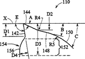
図2に最適に示されるように、すくい面は、先端部40とすくい面突起54との間を延出する長さD1を規定する。この長さD1は、約0.0254cmから約0.1016cmの範囲内である。図示した形態では、すくい面の長さD1は約0.0508cmである。
As best shown in FIG. 2, the rake face defines a length D1 extending between the
図2に示されるように、第2クリアランス面48は、第1クリアランス面44に近接する第1端部と第3クリアランス面50に近接する第2端部とを有する。第2クリアランス面の第1端部は、あさり付けされていない歯(unset tooth)の先端部の切削面Xから下側に深さD2だけ間隔が隔てられている。本発明に基づく深さD2は、約0.0254cmから約0.0762cmの範囲である。図示した形態では、深さD2は約0.03048cmであり、これは、ブレードの通常又は予想される寿命サイクルの期間にこの表面が磨耗することを防ぐために必要とされる最小深さである。
As shown in FIG. 2, the
図3に最適に示されるように、すくい面突起54は、すくい面42の表面から最も突出した表面領域56を規定し、その表面領域56は、あさり付けされていない歯の先端部の切削面から下側に深さD3だけ間隔が隔てられている。この深さD3は、約0.0762cmから約0.254cmの範囲であり、最も好ましくは、約0.1143cmから約0.1905cmの範囲である。また、図2に示されるように、すくい面突起54はすくい面の平面と直交する方向に厚さD4を規定し、この厚さD4は、約0.0127cmから約0.1524cmの範囲が好ましく、約0.0254cmから約0.1016cmの範囲が最も好ましい。
As best seen in FIG. 3, the
S=あさりなしかき歯(raker tooth)
RH=右側、あさりの重い歯
LH=左側、あさりの重い歯
RL=右側、あさりの軽い歯
LL=左側、あさりの軽い歯
本発明の図示形態において、重くあさりの付けられた歯(即ち、図1におけるRH又はLHの歯)は、あさり付けされていない基準歯の先端部面の下側に、約−0.01016cmから約−0.01524cmの範囲で配置される。この深さは各歯のピッチに依存する。
S = clambered tooth (raker tooth)
RH = right side, clam heavy tooth LH = left side clam heavy tooth RL = right side, clam light tooth LL = left side, clam light tooth In the illustrated embodiment of the present invention, heavy clam teeth (ie RH or LH teeth in 1) are placed in the range of about -0.01016 cm to about -0.01524 cm below the tip face of the uncapped reference tooth. This depth depends on the pitch of each tooth.
逃げ角A、B、Cは、上記図1〜図4の形態と同様であることが好ましい。更に、図6の第1クリアランス面144と第2クリアランス面148との間の半径R4は約0.1524cmで、第2クリアランス面148と第3クリアランス面150との間の半径R5は約0.2032cmである。すくい面の長さD1は約0.05842cmで、すくい角Eは約98°(又はあさりのない歯の先端部部間を延びる面に対して垂直な線に対して8°)である。しかしながら、これら角度及び寸法は一例であり、特定の鋸ブレード及び/又は応用(用途)の必要性に応じて適宜変更されうることが、この開示に基づき当業者に認識されるであろう。
The relief angles A, B and C are preferably the same as those in the embodiment shown in FIGS. Furthermore, the radius R4 between the
Applications Claiming Priority (3)
| Application Number | Priority Date | Filing Date | Title |
|---|---|---|---|
| US21889700P | 2000-07-18 | 2000-07-18 | |
| US09/886,627 US6601495B2 (en) | 2000-07-18 | 2001-06-21 | Structural saw blade |
| PCT/US2001/022655 WO2002006020A1 (en) | 2000-07-18 | 2001-07-18 | Structural saw blade |
Publications (3)
| Publication Number | Publication Date |
|---|---|
| JP2004504170A JP2004504170A (en) | 2004-02-12 |
| JP2004504170A5 true JP2004504170A5 (en) | 2006-01-05 |
| JP3870158B2 JP3870158B2 (en) | 2007-01-17 |
Family
ID=26913357
Family Applications (1)
| Application Number | Title | Priority Date | Filing Date |
|---|---|---|---|
| JP2002511941A Expired - Fee Related JP3870158B2 (en) | 2000-07-18 | 2001-07-18 | Structural saw blade |
Country Status (10)
| Country | Link |
|---|---|
| US (1) | US6601495B2 (en) |
| EP (1) | EP1324863B1 (en) |
| JP (1) | JP3870158B2 (en) |
| KR (1) | KR100506547B1 (en) |
| AU (1) | AU2001278950A1 (en) |
| BR (1) | BR0112604B1 (en) |
| CA (1) | CA2415816C (en) |
| MX (1) | MXPA03000521A (en) |
| TW (1) | TW498003B (en) |
| WO (1) | WO2002006020A1 (en) |
Families Citing this family (52)
| Publication number | Priority date | Publication date | Assignee | Title |
|---|---|---|---|---|
| DE19821525B4 (en) * | 1997-05-15 | 2007-05-31 | Amada Co., Ltd., Isehara | sawblade |
| DE59906445D1 (en) * | 1999-11-10 | 2003-09-04 | Graf & Co Ag | sawtooth |
| US6598509B2 (en) | 2001-06-29 | 2003-07-29 | Simonds Industries, Inc. | Cutting tool tooth form including set teeth with surface features and method of making same |
| US7178441B2 (en) * | 2002-12-20 | 2007-02-20 | Kapman Ab | Versatile bandsaw blade |
| AU2003902508A0 (en) * | 2003-05-21 | 2003-06-05 | Anthony Collins | Self supported rasp blade |
| US20040255740A1 (en) * | 2003-06-23 | 2004-12-23 | Troyer Daniel C. | Sawdust clearing band saw blade |
| US7658136B2 (en) * | 2004-12-22 | 2010-02-09 | Black & Decker Inc. | Hole saw blade |
| US7225714B2 (en) * | 2004-12-22 | 2007-06-05 | Black & Decker Inc. | Tooth form design for reciprocating saw blade |
| US7174823B2 (en) * | 2004-09-22 | 2007-02-13 | Irwin Industrial Tool Company | Saw blade having increased tooth stiffness and resistance to fatigue failure |
| CN1947908A (en) * | 2005-10-10 | 2007-04-18 | 库拉图五金工具(上海)有限公司 | Method for processing saw |
| US20070199416A1 (en) * | 2006-02-25 | 2007-08-30 | Cook James T | Band saw blade |
| WO2007098276A2 (en) * | 2006-02-25 | 2007-08-30 | James Timothy Cook | Band saw blade |
| US7913601B2 (en) * | 2006-04-28 | 2011-03-29 | Simonds International Corporation | Enhanced performance saw blade toothform pattern |
| DE502007004103D1 (en) * | 2006-11-24 | 2010-07-22 | Oerlikon Trading Ag | SAWBAND AND METHOD FOR PRODUCING A SAWBAND |
| US8430009B2 (en) * | 2007-01-29 | 2013-04-30 | Maurice Micacchi | Saw tooth for circular saw |
| USD608611S1 (en) | 2007-04-20 | 2010-01-26 | Black & Decker Inc. | Plunge nose reciprocating saw blade |
| US9364907B2 (en) | 2007-12-11 | 2016-06-14 | Black & Decker Inc. | Jigsaw blade |
| US20090145280A1 (en) | 2007-12-11 | 2009-06-11 | Black & Decker Inc. | Reciprocating Saw Blade with Plunge Nose |
| RU2010140369A (en) | 2008-03-04 | 2012-04-10 | Ирвин Индастриал Тул Компани (Us) | TOOLS HAVING WORKING SURFACES FROM SEALED POWDER METAL AND METHOD |
| JP5184172B2 (en) * | 2008-03-26 | 2013-04-17 | 株式会社アマダ | Saw blade |
| USD641766S1 (en) * | 2008-03-26 | 2011-07-19 | Amada Company Limited | Saw blade |
| JP5173670B2 (en) | 2008-08-20 | 2013-04-03 | 株式会社アマダ | Saw blade and manufacturing method thereof |
| JP5238406B2 (en) * | 2008-08-20 | 2013-07-17 | 株式会社アマダ | Band saw blade |
| CN102548697B (en) * | 2009-07-27 | 2015-08-19 | 艾温工业工具公司 | There is saw blade and the correlation technique of single-stage and multistage setting model in pitch model |
| US10189099B2 (en) | 2010-04-22 | 2019-01-29 | Milwaukee Electric Tool Corporation | Saw Blade |
| EP2564966B1 (en) | 2010-04-22 | 2017-04-12 | Milwaukee Electric Tool Corporation | Saw blade |
| US9375796B2 (en) * | 2010-05-07 | 2016-06-28 | Irwin Industrial Tool Company | Saw blade with robust tooth form |
| US9248518B2 (en) | 2010-06-30 | 2016-02-02 | Irwin Industrial Tool Company | Saw blade tooth form for abusive cutting applications |
| US20120042765A1 (en) | 2010-08-20 | 2012-02-23 | Kazda Austin J | Reciprocating saw blade |
| US20120224929A1 (en) * | 2011-03-01 | 2012-09-06 | Anderson James R | Cylindrical cutter |
| USD841417S1 (en) | 2011-04-22 | 2019-02-26 | Milwaukee Electric Tool Corporation | Saw blade |
| CA2770289C (en) | 2011-05-18 | 2019-06-04 | Maurice Micacchi | Saw tooth for circular saw |
| US9731365B2 (en) * | 2011-12-07 | 2017-08-15 | Irwin Industrial Tool Company | Saw blade with tooth form projection |
| US9751134B2 (en) | 2012-07-18 | 2017-09-05 | Milwaukee Electric Tool Corporation | Toothform for a cutting tool, such as a hole saw |
| US9370834B2 (en) | 2013-03-14 | 2016-06-21 | Irwin Industrial Tool Company | Saw blade with feed limiter |
| US10906111B2 (en) * | 2013-07-29 | 2021-02-02 | The M.K. Morse Company | Method of using a cutting blade |
| US20160008899A1 (en) * | 2014-07-14 | 2016-01-14 | Roy A. Hunter | Variable Pitch Blade |
| US10112245B2 (en) | 2015-04-20 | 2018-10-30 | Irwin Industrial Tool Company | Band saw blade |
| US10625353B2 (en) | 2015-09-01 | 2020-04-21 | Wood-Mizer, Llc | Wood cutting band saw blade having reduced kerf dust |
| AT517762A1 (en) * | 2015-10-14 | 2017-04-15 | Voestalpine Prec Strip Gmbh | Cutting tool for cutting flat materials |
| US10166612B2 (en) * | 2016-08-26 | 2019-01-01 | Irwin Industrial Tool Company | Tooth formations and arrangement for a saw blade |
| CN106182449B (en) * | 2016-08-29 | 2018-07-03 | 日照海恩锯业有限公司 | A kind of knife-edge noise reduction hole saw bit and cutting machine |
| US10532412B2 (en) | 2016-09-23 | 2020-01-14 | Milwaukee Electric Tool Corporation | Hole saw arbor assembly |
| US10213854B2 (en) * | 2016-11-14 | 2019-02-26 | Irwin Industrial Tool Company | Band saw blade |
| EP3725441B1 (en) | 2017-01-06 | 2025-04-09 | Milwaukee Electric Tool Corporation | Hole saw |
| US11413693B2 (en) | 2017-05-16 | 2022-08-16 | Milwaukee Electric Tool Corporation | Saw blade |
| USD973733S1 (en) | 2017-08-15 | 2022-12-27 | Milwaukee Electric Tool Corporation | Hole saw |
| US10537951B2 (en) * | 2017-08-16 | 2020-01-21 | Black & Decker Inc. | Band saw blade for cutting structural workpieces |
| CN110039116A (en) * | 2019-05-28 | 2019-07-23 | 湖南泰嘉新材料科技股份有限公司 | A method of optimization bi-metal bandsaw blades weld seam |
| USD948583S1 (en) * | 2019-12-04 | 2022-04-12 | Kapman Ab | Bandsaw blade profile |
| US11440111B2 (en) * | 2020-08-17 | 2022-09-13 | Bmic Llc | Method of using a blade configured to reduce residual foam dust |
| CN112355401A (en) * | 2020-10-14 | 2021-02-12 | 浙江思普锯业有限公司 | Bimetal saw blade with special-shaped tooth groove and small tooth |
Family Cites Families (30)
| Publication number | Priority date | Publication date | Assignee | Title |
|---|---|---|---|---|
| US552370A (en) | 1895-12-31 | Seymour h | ||
| US820969A (en) | 1905-10-26 | 1906-05-22 | Heinrich Grelck | Saw. |
| US1955137A (en) | 1932-06-27 | 1934-04-17 | Lee Lars Paulsen | Steel saw-tooth |
| US2071618A (en) | 1936-01-04 | 1937-02-23 | Arthur M Ferrarl | Method and means for saw-surfacing and cleaning a saw kerf |
| US2126382A (en) | 1936-01-27 | 1938-08-09 | Stockton Box Company | Band saw |
| US3292674A (en) | 1964-01-20 | 1966-12-20 | High Duty Saws Ltd | Saws |
| USRE31433E (en) | 1978-08-28 | 1983-11-01 | Capewell Manufacturing Company | Variable tooth saw blade |
| US4179967A (en) | 1978-08-28 | 1979-12-25 | Stanadyne, Inc. | Variable tooth saw blade |
| US4292871A (en) | 1979-02-01 | 1981-10-06 | The L. S. Starrett Company | Welded edge band saw tooth geometry |
| US4232578A (en) | 1979-07-09 | 1980-11-11 | Wallace Murray Corporation | Saw blade and method of making |
| NZ209377A (en) | 1983-08-30 | 1988-09-29 | South Wales Mini Ind | Bandsaw blade: teeth having triangular (front profile) cutting tip hardened to 900-920 diamond pyramid number |
| US4784033A (en) | 1986-01-22 | 1988-11-15 | Milford Products Corporation | Triple chip ground carbide tip bandsaw blade with ductile filler |
| US5018421A (en) | 1988-04-07 | 1991-05-28 | Armstrong-Blum Manufacturing Company, Ltd. | Saw blade tooth geometry |
| US5606900A (en) | 1992-05-11 | 1997-03-04 | The L.S. Starrett Company | Variable height, high performance, bandsaw blade and method of manufacture therefor |
| JP3283572B2 (en) * | 1992-06-18 | 2002-05-20 | 株式会社アマダ | Band saw blade |
| US5868058A (en) | 1993-07-22 | 1999-02-09 | Manufacture Forezienne De Lames De Scies S.A. | Log mill band-saw blade for initial processing of timber and derivatives thereof |
| DE69535770D1 (en) | 1994-08-19 | 2008-07-31 | Black & Decker Inc | SAW DENTAL FORM AND METHOD FOR THE PRODUCTION THEREOF |
| TW269653B (en) | 1994-08-19 | 1996-02-01 | Black & Decker Inc | Saw blade tooth form and method therefor |
| US5501129A (en) | 1994-09-27 | 1996-03-26 | Armstrong-Blum Manufacturing Company | All purpose saw blade |
| US6167792B1 (en) * | 1995-03-23 | 2001-01-02 | American Saw & Mfg. Company | Tooth form for a saw blade |
| AU5253696A (en) | 1995-03-23 | 1996-10-08 | American Saw And Manufacturing Company | Synchronized variable tooth arrangements for saws |
| US5603252A (en) | 1995-08-28 | 1997-02-18 | Sandvik Ab | Saw blade |
| US5896800A (en) | 1995-09-26 | 1999-04-27 | Black & Decker Inc. | Circular saw blade |
| JP3633217B2 (en) | 1996-09-25 | 2005-03-30 | 松下電工株式会社 | Cutlery and manufacturing method thereof |
| USD438549S1 (en) | 1997-05-08 | 2001-03-06 | Amada Company, Limited | Band saw blade |
| JP4464473B2 (en) | 1997-05-08 | 2010-05-19 | 株式会社アマダ | Band saw blade |
| DE19820430B4 (en) * | 1997-05-08 | 2009-04-09 | Amada Co., Ltd., Isehara | band saw blade |
| DE19739074B4 (en) | 1997-09-08 | 2005-07-07 | WIKUS-Sägenfabrik Wilhelm H. Kullmann GmbH & Co. KG | Saw blade and method for its production |
| JP2001062629A (en) * | 1999-06-22 | 2001-03-13 | Amada Co Ltd | Saw blade |
| US6276248B1 (en) * | 1999-11-05 | 2001-08-21 | American Saw & Manufacturing Company | Band saw blade having reduced noise and uniform tooth loading characteristics |
-
2001
- 2001-06-21 US US09/886,627 patent/US6601495B2/en not_active Expired - Lifetime
- 2001-07-17 TW TW90117402A patent/TW498003B/en not_active IP Right Cessation
- 2001-07-18 AU AU2001278950A patent/AU2001278950A1/en not_active Abandoned
- 2001-07-18 MX MXPA03000521A patent/MXPA03000521A/en active IP Right Grant
- 2001-07-18 EP EP20010957181 patent/EP1324863B1/en not_active Expired - Lifetime
- 2001-07-18 KR KR10-2003-7000736A patent/KR100506547B1/en not_active Expired - Fee Related
- 2001-07-18 BR BR0112604A patent/BR0112604B1/en not_active IP Right Cessation
- 2001-07-18 WO PCT/US2001/022655 patent/WO2002006020A1/en not_active Ceased
- 2001-07-18 CA CA 2415816 patent/CA2415816C/en not_active Expired - Fee Related
- 2001-07-18 JP JP2002511941A patent/JP3870158B2/en not_active Expired - Fee Related
Similar Documents
| Publication | Publication Date | Title |
|---|---|---|
| JP2004504170A5 (en) | ||
| US10569345B2 (en) | Toothform for a cutting tool, such as a hole saw | |
| CN103143775B (en) | Saw blade with tooth form projection | |
| JP2735691B2 (en) | Improved band saw blade | |
| KR100506547B1 (en) | Structural saw blade | |
| CN1143746C (en) | Band saw blade | |
| JP5366512B2 (en) | Saw blade comprising a base and teeth having a cutting edge | |
| JPWO2002042028A1 (en) | Saw blade | |
| GB2113144A (en) | Saw blade | |
| CN101784359A (en) | Jigsaw blade | |
| CN110650829A (en) | Saw blade | |
| US8826790B2 (en) | Saw blade | |
| JP3981297B2 (en) | Saw blade | |
| WO2011014523A1 (en) | Saw blade with single level and multiple level set patterns within pitch patterns, and related method | |
| CN1929946A (en) | Saw blade for wood | |
| JP2616924B2 (en) | Saw blade | |
| WO2005096949B1 (en) | Tooth form design for reciprocating saw blade | |
| JP5941945B2 (en) | Reciprocating blade | |
| EP3321019B1 (en) | Band saw blade | |
| JP6204071B2 (en) | Saw blade for electric saw | |
| JP6204070B2 (en) | Saw blade for electric saw | |
| KR20150003129U (en) | Saw Blade |