JP2004258349A - Projection display device and method of manufacturing projection display device - Google Patents
Projection display device and method of manufacturing projection display device Download PDFInfo
- Publication number
- JP2004258349A JP2004258349A JP2003049283A JP2003049283A JP2004258349A JP 2004258349 A JP2004258349 A JP 2004258349A JP 2003049283 A JP2003049283 A JP 2003049283A JP 2003049283 A JP2003049283 A JP 2003049283A JP 2004258349 A JP2004258349 A JP 2004258349A
- Authority
- JP
- Japan
- Prior art keywords
- light
- color
- image
- switching
- modulating
- Prior art date
- Legal status (The legal status is an assumption and is not a legal conclusion. Google has not performed a legal analysis and makes no representation as to the accuracy of the status listed.)
- Granted
Links
- 238000004519 manufacturing process Methods 0.000 title claims description 8
- 239000004973 liquid crystal related substance Substances 0.000 claims description 159
- 230000002194 synthesizing effect Effects 0.000 claims description 30
- 230000005540 biological transmission Effects 0.000 claims description 26
- 238000000926 separation method Methods 0.000 claims description 21
- 238000000034 method Methods 0.000 claims description 15
- 230000015572 biosynthetic process Effects 0.000 claims description 3
- 238000003786 synthesis reaction Methods 0.000 claims description 3
- 238000010586 diagram Methods 0.000 abstract description 20
- 230000004044 response Effects 0.000 abstract description 15
- 230000010287 polarization Effects 0.000 description 19
- 230000003287 optical effect Effects 0.000 description 17
- 230000001965 increasing effect Effects 0.000 description 11
- 238000004364 calculation method Methods 0.000 description 9
- 230000006870 function Effects 0.000 description 8
- 230000008859 change Effects 0.000 description 6
- 241001270131 Agaricus moelleri Species 0.000 description 5
- 238000012937 correction Methods 0.000 description 5
- 238000002360 preparation method Methods 0.000 description 5
- 238000002834 transmittance Methods 0.000 description 5
- 238000006243 chemical reaction Methods 0.000 description 4
- 230000003247 decreasing effect Effects 0.000 description 4
- QSHDDOUJBYECFT-UHFFFAOYSA-N mercury Chemical compound [Hg] QSHDDOUJBYECFT-UHFFFAOYSA-N 0.000 description 4
- 229910052753 mercury Inorganic materials 0.000 description 4
- 230000000694 effects Effects 0.000 description 3
- 239000003086 colorant Substances 0.000 description 2
- 238000009826 distribution Methods 0.000 description 2
- 238000010521 absorption reaction Methods 0.000 description 1
- 230000008901 benefit Effects 0.000 description 1
- 230000023077 detection of light stimulus Effects 0.000 description 1
- 238000011161 development Methods 0.000 description 1
- 238000005516 engineering process Methods 0.000 description 1
- 230000002708 enhancing effect Effects 0.000 description 1
- 230000004907 flux Effects 0.000 description 1
- 239000011521 glass Substances 0.000 description 1
- 239000011159 matrix material Substances 0.000 description 1
- 229910001507 metal halide Inorganic materials 0.000 description 1
- 150000005309 metal halides Chemical class 0.000 description 1
- 238000012986 modification Methods 0.000 description 1
- 230000004048 modification Effects 0.000 description 1
- 238000011160 research Methods 0.000 description 1
- 238000012827 research and development Methods 0.000 description 1
- 229910052724 xenon Inorganic materials 0.000 description 1
- FHNFHKCVQCLJFQ-UHFFFAOYSA-N xenon atom Chemical compound [Xe] FHNFHKCVQCLJFQ-UHFFFAOYSA-N 0.000 description 1
Images


Landscapes
- Liquid Crystal (AREA)
- Projection Apparatus (AREA)
- Transforming Electric Information Into Light Information (AREA)
- Video Image Reproduction Devices For Color Tv Systems (AREA)
Abstract
【課題】本発明は、高精度の振幅制御や高速応答化或いは微細化等を伴うことなく多階調化できるようにした投射型表示装置を提供することを目的とする。
【解決手段】複数の光変調手段30A,30Bにより形成された、互いに異なる階調の画像光を合成,投射することで、個々の光変調手段30A,30Bよりも個階調が高く、ダイナミックレンジの広い画像表示が可能となる。
【選択図】 図1An object of the present invention is to provide a projection-type display device capable of performing multiple gradations without involving high-accuracy amplitude control, high-speed response, or miniaturization.
Kind Code: A1 Abstract: By combining and projecting image lights having different gray levels formed by a plurality of light modulating units, the individual gray levels are higher than the individual light modulating units, and a dynamic range is provided. Image can be displayed.
[Selection diagram] Fig. 1
Description
【0001】
【発明の属する技術分野】
本発明は、投射型表示装置及び投射型表示装置の製造方法に関し、特に、多階調表示が可能な表示技術に関するものである。
【0002】
【従来の技術】
表示装置の分野では、色再現が表示品質に大きく影響するため、従来より、このような表示性能を高めるための研究開発が盛んに行なわれており、例えば色再現範囲を広める研究がある(非特許文献1参照)。
また一方で、明暗の知覚(以後、階調と呼ぶ)を再現すること(調子再現)も表示品質に影響し、オリジナルを再現するにはダイナミックレンジが広く、多階調である方が種々の画像を再現するには望ましい。ところで、多階調で表示を行なう手法としては、一般に、印加電圧を増減することで出力される光の光量を変化させる振幅変調方式や、光の出力面積を変えることで光量調整を行なう空間変調方式、或いは光の出射時間を増減することで光量調整を行なう時間変調方式等が知られている。また、一枚の表示パネルにおいて、これらの方式を組み合わせることで、多階調化を図ることも考えられる。
【0003】
【非特許文献1】
“Development of Six−Primary HDTV−Display System”,H.Motomura et.al.,EURODISPLAY 2002,p.563−p.566
【0004】
【発明が解決しようとする課題】
しかしながら、振幅変調により多階調化するためには、印加電圧の振幅を高精度で制御しなければならず、高価なICチップが必要となる。また、時間変調で多階調化するためには、駆動周波数を上げる必要があり、高速応答性が要求される。さらに、空間変調により多階調化するためには、1画素を細かく分割しなければならず微細化が必要となる。このように、いずれの方式を採用した場合でも、多階調化には一定の限界がある。
本発明は、上述の課題に鑑み創案されたもので、高精度の振幅制御や高速応答化或いは微細化等を伴うことなく多階調化できるようにした投射型表示装置及び投射型表示装置の製造方法を提供することを目的とする。
【0005】
【課題を解決するための手段】
上記目的を達成するために、本発明の投射型表示装置は、光源と、上記光源から出射された光を変調して互いに異なる階調の画像光を形成する複数の光変調手段と、上記複数の光変調装置で形成された各画像光を合成する合成手段と、上記合成手段で合成された画像光を拡大投影する投射手段とを備えたことを特徴とする。
【0006】
本構成では、互いに異なる複数の階調の画像光を空間的に重ね合わせて合成することで1つの画像を形成しているため、低階調の光変調手段を用いながらそれよりも高階調の画像表示が可能となり、又、ダイナミックレンジも広げることができる。なお、上記光源としては、メタルハライドランプや高圧水銀ランプ、キセノンランプ等の白色光源や、カラーLED等の色光源を用いることができる。また、本発明では、光の変調方法として、印加電圧を増減することで出力される光の光量を変化させる振幅変調方式や、光の出力面積を変えることで光量調整を行なう空間変調方式、或いは光の出射時間を増減することで光量調整を行なう時間変調方式のいずれを用いてもよい。
【0007】
また、フルカラー表示を可能とすべく、投射型表示装置を、複数の色光源と、上記色光源に対応して設けられた複数の光変調手段と、上記複数の光変調手段から出力された光を合成する合成手段と、上記合成手段で合成された光を拡大投影する投射手段とを備えて構成するとともに、上記光変調手段を少なくとも1つの色光源に対して複数設け、上記1つの色光源に対応して設けられた複数の光変調手段から互いに異なる階調の画像光を出力してもよい。この構成では、R(赤),G(緑),B(青)等の複数の色光源の内、少なくとも1つの色光源に対して、独立に階調制御される光変調手段を複数設けているため、多階調化が可能となる。勿論、独立に階調制御される複数の光変調手段を、各色光源に対応して複数組設けてもよい。
【0008】
また、1つの光源から出射された光を複数の色光に分離し、各色光をそれぞれ変調することにより、フルカラー化を図ってもよい。すなわち、投射型表示装置を、白色光源と、上記光源から出射された白色光を互いに異なる複数の色光に分離する色分離手段と、分離された上記各色光に対応して設けられた複数の光変調手段と、上記複数の光変調手段から出力された光を合成する合成手段と、上記合成手段で合成された光を拡大投射する投射手段とを備えて構成するとともに、上記光変調手段を、分離された少なくとも1つの色光に対して複数設け、上記1つの色光に対応して設けられた複数の光変調手段から互いに異なる階調の画像光を出力してもよい。この構成では、白色光をR(赤),G(緑),B(青)等の複数の色光に分離した後、分離された少なくとも1つの色光に対して、独立に階調制御される光変調手段を複数設けているため、多階調化が可能となる。勿論、独立に階調制御される複数の光変調手段を、各色光に対応して複数組設けてもよい。
【0009】
また、本発明の投射型表示装置は、白色光源と、上記光源から出射された白色光に含まれる複数の色光の内のいずれかを時分割で切替可能な色切替手段と、上記色切替手段から出射された光を変調する複数の光変調手段と、上記複数の光変調手段から出力された光を合成する合成手段と、上記合成手段で合成された光を拡大投射する投射手段とを備え、上記複数の光変調手段は、上記色切替手段より順次出力される少なくとも1つの色光を変調して互いに異なる階調の画像光を形成することを特徴とする。
【0010】
本構成は、色切替手段により時分割で切り替えて出射された各色光を、互いに階調の異なる複数の画像光を時分割で出力するようにしたものである。本投射型表示装置では、光源から出射された白色光は、色切替手段により互いに異なる複数の色光に分離され、各色光が時分割で順次出力される。ここで、色切替手段は例えば面内にR,G,Bのダイクロイックミラーが回転方向に順に配置された回転式のカラーホイールとして構成され、光源光がいずれかのダイクロイックミラーを通過することで対応する色光が光変調手段に出力される。また、少なくとも一つの色光に対して複数の光変調手段が設けられ、これらの複数の光変調手段により互いに異なる階調の画像光が形成され、合成手段に順次出力される。
したがって、本構成でも上記各構成のものと同様に、低階調の光変調手段を用いながらそれよりも高階調の画像表示が可能となり、又、ダイナミックレンジも広げることができる。
【0011】
また、本発明の投射型表示装置は、光源と、上記光源から出射された光の方向を複数の光変調手段に対して時間的に切り替えて出力する光切替手段と、上記光切替手段の切り替えタイミングに応じて上記複数の光変調手段から順次出力された光を経時的に合成する合成手段と、上記合成手段により合成された光を拡大投影する投射手段とを備え、上記複数の光変調手段は、上記光切替手段から出力された光を変調して互いに異なる階調の画像光を形成することを特徴とする。
【0012】
本構成は互いに階調の異なる複数の画像光を時分割で出力するようにしたものである。本投射型表示装置では、光源から出射された光は、まず、光切替手段によりその出射方向を複数の光変調手段の間で時分割的に切り替えられる。ここで、上記光切替手段は例えば面内に開口部を有する回転式のミラーホイールとして構成され、光源光が上記開口部を通過することで光を一の光変調手段に出力でき、光源光が非開口部であるミラー面で反射することで、光の出力方向が他の光変調手段に切り替えられる。そして、各光変調手段により互いに異なる階調の画像光が形成され、合成手段に順次出力される。
【0013】
したがって、本構成でも上記各構成のものと同様に、低階調の光変調手段を用いながらそれよりも高階調の画像表示が可能となり、又、ダイナミックレンジも広げることができる。なお、光源光を複数の光変調手段に順次切り替えて出力する代わりに、複数の光変調手段で形成された各画像光を順次で切り替えて投射するようにしてもよい。すなわち、本発明の投射型表示装置は、光源と、上記光源から出射された光を変調して互いに異なる階調の画像光を形成する複数の光変調手段と、上記複数の光変調手段で形成された複数の画像光を時間的に切り替えて出力する光切替手段と、上記光切替手段から出力された画像光を拡大投影する投射手段とを備えたことを特徴とする。この構成でも同様の効果が得られる。
【0014】
上述のように複数の光変調手段により複数の画像光を時分割で切り替えて表示する場合、光源光が選択的に一の光変調手段に対してのみ出力され、この選択された光変調手段により画像光が形成されている間(表示期間)、他の光変調手段の応答する時間に余裕が生まれる。このため、この期間に他の光変調手段において割り込み等の表示のための動作を行なうことで、例えば、光変調手段として液晶装置等の応答速度の遅い装置を用いた場合でも、見かけ上の応答速度を上げることができる。また、光変調手段として液晶装置を用いる場合、各液晶装置は中間調をとらない透過又は非透過の2状態のみ許容する構成とすることが好ましい。このように白表示(透過状態)と黒表示(非透過状態)の2値状態のみ許容することで、光変調手段として用いられる各液晶装置の応答時間を短くでき、見かけ上の応答速度を更に高めることができる。また、TN(Twist Nematic)モードなどの液晶モードは中間調状態の方が視角特性に異方性が大きい。これは液晶分子がある方向にある傾きを持って分布しているためである。プロジェクターの光学系のような等方的な光強度分布をもつ光源では、視角特性のために面内ムラが生じ、また光利用効率も悪くなる。白黒状態では液晶分子の分布は全体では比較的等方的で、界面の位相差も補償し合うので視角特性が向上する利点がある。
【0015】
なお、上記構成において、上記光源と上記光切替手段との間に、光源光に含まれる複数の色光の内のいずれかを時分割で切替可能な色切替手段を設け、上記色切替手段により一の色光が選択されている期間内に上記光切替手段が上記一の色光を上記複数の光変調手段に切り替えて出力することが好ましい。これにより、フルカラー表示が可能となる。例えば、第1のタイミングにおいて色切替手段によりR光が透過されると、このR光は光切替手段の切り替えタイミングに応じて複数の光変調手段に時分割で出力され、互いに階調の異なるRの画像光が形成される。そして、第2のタイミングにおいて色切替手段によりG光が透過されると、このG光は光切替手段の切り替えタイミングに応じて複数の光変調手段に時分割で出力され、互いに階調の異なるGの画像光が形成される。同様に、第3のタイミングにおいて色切り替え手段によりB光が透過されると、このB光は光切替手段の切り替えタイミングに応じて複数の光変調手段に時分割でされ、互いに階調の異なるRの画像光が形成される。
【0016】
また、上記構成において、上記光源と上記光切替手段との間に、光源光に含まれる複数の色光の内のいずれかを時分割で切替可能な色切替手段を更に設け、上記色切替手段とともに、一の色光が選択されている期間内に上記光切替手段が上記一の色光を一の光変調手段に出力すると同時に、二の色光を選択して二の光変調手段に出力することが好ましい。これにより、同時に一の色光と二の色光を表示に寄与させることができ、光利用効率を高めることができる。
【0017】
ここで、色切替手段は例えば面内にR,G,Bのダイクロイックミラーが回転方向に順に配置された回転式のカラーホイールとして構成され、光源光がいずれかのダイクロイックミラーを通過することで対応する色光を一の光変調手段に出力し、他の色光を他の光変調手段に出力することができる。そして、このようなカラーホイールを複数組み合わせることで、各光変調手段に対してR,G,Bのいずれかの色光を時間的に切り替えて出力することができる。そして、第1〜第3のタイミングで形成された各色の画像光が経時的に合成されて、フルカラー表示が実現される。また、この構成では、各色の画像光を時分割で表示しているため、光変調手段を各色光に対してそれぞれ設ける必要がなく、各色の画像光を同時に出力するものに比べて装置構成を簡素化できる利点もある。
【0018】
また、本発明の投射型表示装置は、光源と、上記光源から出射された光を互いに異なる複数の色光に分離し、分離された上記各色光の出射方向を複数の光変調手段に対して時間的に切り替えて出力する色分離/切替手段と、上記色分離/切替手段の切り替えタイミングに応じて上記複数の光変調手段から順次出力された光を経時的に合成する合成手段と、上記合成手段により合成された光を拡大投影する投射手段とを備え、上記複数の光変調手段は、上記色分離/切替手段から出力された色光を変調して互いに異なる階調の画像光を形成することを特徴とする。
【0019】
本構成では、光源から出射された光は、色分離/切替手段により複数の色光に分離され、それぞれ複数の光変調手段に出力される。また、各光変調手段に出力される色光は時間的に切り替えられるようになっており、互いに階調の異なる同一色の画像光が複数の光変調手段により異なるタイミングで形成される。例えば、本構成では、光源光が第1のタイミングにおいて第1の色光,第2の色光に分離され、それぞれ第1の光変調手段,第2の光変調手段に出力される。また、第2のタイミングにおいて、第1の色光,第2の色光はそれぞれ第2の光変調手段,第1の光変調手段に出力される。この際、第1のタイミングにおいて第1の光変調手段で形成された第1の色の画像光と、第2のタイミングにおいて第2の光変調手段で形成された第1の色の画像光とは、互いに独立に階調制御される。同様に、第1のタイミングにおいて第2の光変調手段で形成された第2の色の画像光と、第2のタイミングにおいて第1の光変調手段で形成された第2の色の画像光とは、互いに独立に階調制御される。
【0020】
ここで、色分離/切替手段は例えば面内にR,G,Bのダイクロイックミラーが回転方向に順に配置された回転式のカラーホイールとして構成され、高原光がいずれかのダイクロイックミラーを通過することで対応する色光を一の光変調手段に出力し、他の色光を他の光変調手段に出力することができる。そして、このようなカラーホイールを複数組み合わせることで、各光変調手段に対してR,G,Bのいずれかの色光を時間的に切り替えて出力することができる。そして、異なるタイミングで別々の光変調手段により形成された同一色の画像光が順次合成手段に出力される。
【0021】
したがって、本構成でも簡素な構成でフルカラー表示が可能となる。また、本構成では、光源から出力された光を複数の光変調手段に対して時分割で振り分けて出力しているため、色切替手段により光の透過と反射(又は吸収)とを切り替える構成に比べて光利用効率が高く、明るい表示が可能となる。
【0022】
また、本発明の投射型表示装置は、光源と、上記光源から出射された光を互いに異なる複数の色光に分離する色分離手段と、上記色分離手段から出射された光を変調して互いに異なる階調の画像光を形成する複数の光変調手段と、上記複数の光変調手段で形成された複数の画像光を時間的に切り替えて出力する光切替手段と、上記光切替手段から出力された画像光を拡大投影する投射手段とを備えたことを特徴とする。本構成でも、低階調の光変調手段を用いながらそれよりも高階調の画像表示が可能となり、又、ダイナミックレンジも広げることができる。
【0023】
なお、上記構成において、上記光源から出射された光が上記光切替手段により一の光変調手段に出力されている間、他の光変調手段は表示のための動作を行なうことが好ましい。これにより、例えば、光変調手段として液晶装置等の応答速度の遅い装置を用いた場合でも、見かけ上の応答速度を上げることができる。また、光変調手段として液晶装置を用いる場合、各液晶装置は中間調をとらない透過又は非透過の2状態のみ許容する構成とすることが好ましい。このように白表示(透過状態)と黒表示(非透過状態)の2値状態のみ許容することで、光変調手段として用いられる各液晶装置の応答時間を短くでき、見かけ上の応答速度を更に高めることができる。
【0024】
なお、上記各構成において、1つの色光(又は、単一の光源)に対して複数設けられた光変調手段には、少なくとも互いにダイナミックレンジの異なる第1の光変調手段と第2の光変調手段とが含まれることが好ましい。例えば、第1の光変調手段と第2の光変調手段との階調数がそれぞれn階調,m階調であり、第2の光変調手段の1階調が第1の光変調手段の1階調をm等分したものである場合、表示可能な階調数は各光変調手段の表示可能な階調数の積(即ち、n×m階調)で表わされ、階調再現性を格段に向上させることができる。
【0025】
このように第1の光変調手段と第2の光変調手段とのダイナミックレンジを異ならせる方法としては、例えば、各光変調手段の開口率を異ならせる方法がある。また、第1の光変調手段と第2の光変調手段とに入射される光源光の強度を異ならせることで、各光変調手段のダイナミックレンジを異ならせてもよい。
また、本発明の投射型表示装置の製造方法は、光源と、上記光源から出射された光を変調して互いに異なる階調の画像光を形成する複数の光変調手段と、上記複数の光変調手段で形成された各画像光を合成する合成手段と、上記合成手段で合成された画像光を拡大投影する投射手段とを形成することを特徴とする。
【0026】
【発明の実施の形態】
[第1実施形態]
図1〜図6を参照しながら本発明の第1実施形態に係る投射型表示装置について説明する。図1は本実施形態の投射型表示装置の全体構成を示す機能ブロック図、図2はその要部の機能ブロック図、図3,図4はいずれもその動作を説明するための図、図5,図6はいずれも本投射型表示装置の要部構成を示す模式図である。なお、以下の全ての図面においては、図面を見やすくするため、各構成要素の膜厚や寸法の比率などは適宜異ならせてある。
【0027】
図1に示すように、本実施形態の投射型表示装置は、R(赤)、G(緑)、B(青)の画像データを入力する画像データ入力部10と、各色の画像データを互いに異なる階調データに分解してそれぞれ複数(例えば図1では2つ)の画像形成部30A,30Bに出力する信号出力部20と、各画像形成部30A,30Bで形成された画像光を合成し、スクリーン50に拡大投影する合成/投射部40とを備えている。
【0028】
図2に示すように、信号出力部20は、ルックアップテーブル21と表示信号演算部22とを機能的に備えており、画像信号入力部10から入力されたR,G,Bの画像データを、互いに異なる階調データに分解して出力するようになっている。具体的には、表示信号演算装置22は、ルックアップテーブル21に基づいて各色の画像データをそれぞれ主階調用の階調データと微階調用の階調データとに分解し、階調補正を施した後、それぞれ画像形成部30A,30Bに出力するようになっている。
【0029】
図5,図6は、画像形成部30A,30B及び合成/投射部40を含む本投射型表示装置の全体的な光学系を示す模式図である。図5に示すように、本投射型表示装置は、高圧水銀ランプ等の白色光源31と、この光源31から出射された光を互いに異なる偏光(p偏光,s偏光)に分離する偏光分離部32と、分離された偏光をそれぞれ入射され互いに異なる階調の画像光を形成する複数の画像形成部30A,30Bと、各画像形成部30A,30Bで形成された画像光を合成する合成部(合成手段)41と、合成された画像光をスクリーンに拡大投影する投射レンズ(投射手段)42とを備えている。ここで、合成部41と投射レンズ42とにより合成/投射部40が構成されている。
【0030】
画像形成部30A、30Bは同様の構成を有するため、図6では画像形成部30としてその概略構成を示し、両者を区別する場合には、画像形成部30A,画像形成部30Bに対応して各部材の符号にA又はBを付す。
図6に示すように、画像形成部30は、偏光分離部32から入射された偏光を互いに異なる複数の色光に分離するためのダイクロイックミラーDM1〜DM3,反射ミラーM3,M4からなる色分離手段と、分離された各色光に対応して設けられた複数の透過型液晶装置(光変調手段)301〜303と、各液晶装置301〜303で形成された画像光を合成するためのダイクロイックプリズムDPからなる色合成手段とを備えている。
【0031】
ダイクロイックミラーDM1,DM2は、例えばガラス表面に誘電体多層膜を積層したもので、所定の色光を選択的に反射し、それ以外の波長の光を透過するようになっている。すなわち、赤色光反射のダイクロイックミラーDM1は、光源31からの光束のうち青色光B,緑色光Gを透過し、赤色光Rを反射する。また、緑色光反射のダイクロイックミラーDM2は、ダイクロイックミラーDM1を透過した緑色光Gと青色光Bの内、青色光Bを透過し、緑色光Gを反射する。これにより、光源31から入射された光の内、青色光BはダイクロイックミラーDM1,DM2を透過した後、ミラーM4,M5で反射されて青色用の液晶装置303に入射される。また、緑色光GはダイクロイックミラーDM1を透過し、ダイクロイックミラーDM2で反射された後、緑色用の液晶装置302に入射される。赤色光RはダイクロイックミラーDM1で反射された後、ミラーM3で反射されて赤色用の液晶装置301に入射される。
【0032】
液晶装置301〜303は、例えばアクティブマトリクス型の透過型液晶装置として構成されている。そして、入射された色光を変調して対応する色の画像光を形成し、ダイクロイックプリズムDPに出力するようになっている。ダイクロイックプリズムDPは、4つの直角プリズムが貼り合わされた構造となっており、その内面に赤色光Rを反射するミラー面と青色光Bを反射するミラー面とが十字状に形成されている。そして、三つの色光R,G,Bがこれらのミラー面によって合成されてカラー画像を表わす光が形成されるようになっている。そして、各画像形成部30A,30BのダイクロイックプリズムDPA,DPBから出射された光は、直接或いはミラーM2により反射されてそれぞれ合成部41に入射され、各カラー画像光が合成され、投射レンズ42によりスクリーン上に拡大投影されるようになっている。
【0033】
なお、偏光分離部32及び合成部41は偏光ビームスプリッタからなり、画像形成部30Aの各液晶装置301A〜303Aから出力される画像光の偏光方向と画像形成部30Bの各液晶装置301B〜303Bから出射される画像光の偏光方向とは、合成部41に入射される際に互いに直交するようになっている。この偏光ビームスプリッタには反射偏光膜が形成され、入射された光の内、p偏光を透過し、s偏光を反射するようになっている。このため、例えば光源31から偏光分離部32に入射された光(p偏光とs偏光とが混在した光)の内、p偏光は偏光分離部32を透過して画像形成部30Bに入射し、s偏光は偏光分離部32により反射されミラーM1を介して画像形成部30Aに入射される。ここで、例えば液晶装置301A〜303A及び液晶装置301B〜303BはノーマリホワイトのTN型液晶装置として構成されており、各液晶装置301A〜303A,301B〜303Bの入射光側の偏光板はそれぞれ入射される光の偏光方向に対して平行(もしくは垂直)な透過軸を有し、出射光側の偏光板は入射光側の偏光板に垂直な方向の透過軸を有している。よって、画像形成部30Aからはp偏光が出射され、画像形成部30Bからはs偏光が出射される。合成部41に入射したp偏光の画像光は合成部41を透過し、画像形成部30BからミラーM2を介して合成部41に入射したs偏光の画像光は合成部41で反射される結果、両画像光は合成されてスクリーン50上に投影される。
【0034】
ここで、上述した合成手段の構成は一例にすぎず、例えばノーマリーブラックのTNモードを用いる場合や、ミラーで光を反射する表示装置(例えばDMD(Digital Mirror Device)など)を偏光方向を変えないように配置する場合などは入射の偏光と同じ偏光が出射されるので、上記と同じ考え方で偏光ビームスプリッタの配置を変えればよい。
【0035】
ところで、本実施形態では、同一の色光に対応する各画像形成部30A,30Bの液晶装置(即ち、液晶装置301Aと液晶装置301B、液晶装置302Aと液晶装置302B、液晶装置303Aと液晶装置303B)は独立に階調制御されるようになっており、互いに異なる階調の画像光を合成することで多階調化を図っている。また、各色光について複数設けられた各液晶装置(例えば液晶装置301A,301B)は互いにダイナミックレンジが異なり、一方が主画像を形成する主階調用の液晶装置、他方が主画像を微調整するための微階調用の液晶装置として構成されている。
【0036】
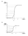
図3は赤色用の液晶装置301A,301Bの電圧−透過率特性を示す図である。液晶装置301Aは、図3(a)に示すように、1階調の刻み幅の広い主階調用の液晶装置として機能し、例えばn階調(T1〜Tn)の表示が可能となっている。一方、液晶装置301Bは、図3(b)に示すように、1階調の刻み幅の狭い微階調用の液晶装置として機能する。液晶装置301Bはm階調(t1〜tm)の表示が可能であり、その1階調の刻み幅は例えば主階調の1階調T1をm等分したものとなっている。したがって、投射型表示装置全体として表示可能な階調数は、各液晶装置301A,301Bの階調数の積(即ちn×m階調)で表わされ、極めて階調再現性の高い表示装置となっている。なお、液晶装置301A,301Bのダイナミックレンジを異ならせる方法としては、各液晶装置301A,301Bについて画素の開口率を変えたり、液晶装置301A,301Bに入射される光の光量を変えたりする方法がある。また、画像信号を出力するICにおいて参照電圧を変えることで抵抗分割される刻み幅が変わり、ダイナミックレンジを異ならせることができる。また、階調特性は同じままダイナミックレンジを広げたい場合は複数の表示装置に互いに同じ階調の画像光を出せばいい。よって、画素の開口率を変えるよりは入射光量を変えたり、画像信号を変える方式の方が同じ液晶装置を使えるためより好ましい。
【0037】
同様に、画像形成部30Aの液晶装置302A,303Aはそれぞれ緑色光,青色光に対する主階調用の液晶装置として機能し、画像形成部30Bの液晶装置302B、303Bは、それぞれ緑色光,青色光に対する微階調用の液晶装置として機能する。
【0038】
このような構成において、画像データ入力部10から信号出力部20にRGB信号などの画像データが入力されると(図4(a)参照)、表示信号演算部22はルックアップテーブル21に基づいて、各フレームの色画像毎に主階調用の階調データ1AR〜1AB,2AR〜2AB,・・・と微階調用の階調データ1BR〜1BB,2BR〜2BB,・・・とを作成し、各液晶装置301A〜303A,301B〜301Bに出力する(図4(b)参照)。そして、各液晶装置301A〜303A,301B〜301Bで形成された主階調用及び微階調用の画像光が同時に合成され、スクリーン50上にカラー画像として表示される。
【0039】
したがって、本実施形態の投射型表示装置によれば、互いに異なる複数の階調の画像光を空間的に重ね合わせて合成しているため、個々の液晶装置の表示可能な階調数が少ない場合でも、その組合せにより投射型表示装置全体として高い階調再現性が得られ、又ダイナミックレンジも広げることができる。
特に、各色光に対して複数設けられた液晶装置のダイナミックレンジを互いに異ならせているため、投射型表示装置全体として表示可能な階調数を格段に高めることができる。
【0040】
[第2実施形態]
次に、図7〜図11を参照しながら本発明の第2実施形態に係る投射型表示装置について説明する。なお、本実施形態において上記第1実施形態と同様の部位については同じ符号を付し、その説明を省略する。
【0041】
本実施形態の投射型表示装置は、主たる画像光と微調整用の画像光とを時分割的に表示するようにしたものであり、図7に示すように、R(赤)、G(緑)、B(青)の画像データを入力する画像データ入力部10と、光源31から出射された光の出射方向を画像形成部30A′,30B′の間で切り替え可能な光路切替部36と、各色の画像データを互いに異なる階調データに分解し各階調データを光路切替部36の切り替えタイミングに合わせてそれぞれ画像形成部30A′,30B′に出力する信号出力部20′と、各画像形成部30A′,30B′で形成された画像光を合成し、スクリーン50に拡大投影する合成/投射部40′とを備えている。
【0042】
本実施形態において、信号出力部20′は、ルックアップテーブルと表示信号演算部(いずれも図示略)とを機能的に備えており、画像信号入力部10から入力されたR,G,Bの画像データを互いに異なる階調データに分解して出力するようになっている。具体的には、表示信号演算部はルックアップテーブルに基づいて各色の画像データをそれぞれ主階調用の階調データと微階調用の階調データとに分解し、階調補正を施す。また、表示信号演算部はクロック発生部60から出力される同期信号により光路切替部36と同期して駆動され、階調補正の施された主階調用の階調データと微階調用の階調データとを、光路切替部36の切り替えタイミングに合わせて、それぞれ画像形成部30A′,画像形成部30B′に対して順に出力するようになっている。
【0043】
図8は、本投射型表示装置の全体的な光学系を示す模式図である。本投射型表示装置は、高圧水銀ランプ等の白色光源31と、この光源31から出射された光(p偏光とs偏光とが混在した光)を一偏光(例えばp偏光)に変換する偏光変換部35と、偏光変換された光を互いに異なる複数の色光に分離し、分離された各色光をそれぞれ画像形成部30A′,30B′に出力するカラーホイール361,362からなる色分離/切替部(色分離/切替手段)36と、各画像形成部30A′,30B′で形成された画像光を合成する合成部(合成手段)41′と、合成された画像光をスクリーン50に拡大投影する投射レンズ(投射手段)42とを備えている。ここで、合成部41′と投射レンズ42とにより合成/投射部40′が構成されている。
【0044】
カラーホイール361(362)は回転可能なダイクロイックミラーのホイールであり、図9(a)に示すように、回転面内に、赤色透過用、緑色透過用、青色透過用の扇形のダイクロイックミラー361R(362R),361G(362G)、361B(362B)が回転方向に沿って例えば順に6つ配置されている。これらのダイクロイックミラーはいずれかの色光を透過し、それ以外の色光を反射するようになっており、カラーホイールを回転して光源光が入射される位置(即ち、光源光が入射されるダイクロイックミラー)を変えることで、色光の光路(出射方向)を切り替えることができるようになっている。また、カラーホイール361,362は、1フィールド期間内に画像形成部30A′,30B′にR,G,Bの各色光が入射されるように、例えば、1フィールド期間に半回転するようになっている。また、例えば1フィールド期間に1回転するようにして、1フィールド期間中のR、G、Bの画像を分散させるように表示すれば色割れの抑制効果が得られる。
【0045】
この2つのカラーホイール361,362は、図9(b)に示すような位相で互いに同期して回転している。すなわち、カラーホイール361,362が回転した際に、カラーホイール361で反射された光の光路L上で、ダイクロイックミラー361Gとダイクロイックミラー362R、ダイクロイックミラー361Bとダイクロイックミラー362G、ダイクロイックミラー361Rとダイクロイックミラー362Bが対向するような位相を保って回転している。このため、例えば、光源31から出射された白色光があるタイミングにおいてダイクロイックミラー361Rに入射されると、図10に示すように、この光の内、赤色光が透過され、ミラーM6を介して画像形成部30A′に入射する。一方、入射された光の内、緑色光,青色光はダイクロイックミラー361Rで反射され、ダイクロイックミラー362Bに入射されて青色光のみ透過される。そして、ダイクロイックミラー362Bを透過した赤色光はミラーM7を介して画像形成部30B′に入射される。この結果、上記タイミングにおいて、画像形成部30A′では赤色の画像光が形成され、画像形成部30B′では青色の画像光が形成される。
【0046】
本実施形態において、画像形成部30A′,30B′はいずれも単板の透過型液晶装置(光変調手段)として構成され、各液晶装置30A′,30B′は色分離/切替部36の切り替えタイミングに合わせてそれぞれ画像光を形成するようになっている。また、液晶装置30A′,30B′は、出射される画像光の偏光方向が合成部41′に入射される際に互いに直交するように構成されている。例えば、液晶装置30A′,30B′はそれぞれノーマリブラックモード,ノーマリホワイトモードの構成を有しており、液晶装置30A′,30B′から合成部41′に対してそれぞれp偏光,s偏光の画像光が出射されるようになっている。
【0047】
また、液晶装置30A′,30B′は互いに独立に階調制御されるようになっており、互いに異なる階調の画像光を合成することで多階調化を図っている。また、液晶装置30A′,30B′は互いにダイナミックレンジが異なり、液晶装置30A′が主画像を形成する主階調用の液晶装置、液晶装置30B′が主画像を微調整するための微階調用の液晶装置として機能する。なお、各液晶装置30A′,30B′の電圧−透過率特性は、それぞれ図3(a),図3(b)に示したものと同様であり、液晶装置30A′,30B′の画像光を合成することでn×m階調の画像表示が可能となっている。
【0048】
合成部41′は偏光ビームスプリッタからなり、反射偏光膜41a′により、合成部41′に対して入射された光の内、p偏光を透過し、s偏光を反射するようになっている。このため、液晶装置30A′から合成部41′に入射したp偏光の画像光は反射偏光膜41a′を透過し、液晶装置30B′から合成部41′に入射したs偏光の画像光は反射偏光膜41a′に反射される結果、両画像光は合成されてスクリーン50上に投影されるようになっている。
【0049】
このような構成において、画像データ入力部10から信号出力部20′に画像データが入力されると(図11(a)参照)、信号出力部20′は各フィールドの色画像毎に主階調用の階調データ1AR〜1AB,2AR〜2AB,3AR〜3AB,・・・と微階調用の階調データ1BB〜1BG,2BB〜2BG,3BB〜3BG,・・・とを作成する。
【0050】
一方、光源31から出射された光は、偏光変換部35により一偏光に変換され、カラーホイール361,362によりR,G,Bの各色光に分離される。そして、1フィールド期間内に、画像形成部30A′に対してR,G,Bの色光を順に出力し、同時に画像形成部30B′に対してB,R,Gの色光を順に出力する。
【0051】
この際、カラーホイール361,362の回転に同期して、信号出力部20′から各画像形成部30A′,30B′にそれぞれ主階調データ,微階調データが出力される。具体的には、信号出力部20′は、画像形成部30A′にR,G,Bの色光が時間順次に出力される際に、これと同期して画像形成部30A′に対して赤色用,緑色用,青色用の主階調データ1AR,1AG,1ABを時間順次に出力する。また、同時に、画像形成部30B′に対して青色用,赤色用,緑色用の微階調データ1BB,1BR,1BGを時間順次に出力する(図11(b)参照)。すなわち、同じ色の主階調用の画像光と微階調用の画像光とは異なるタイミングで形成される。そして、各色毎に各画像形成部30A′,30B′から時間をずらして出力された画像光が合成部41′に順次出力され、これらの色画像が1フィールド期間内に合成される結果、スクリーン50上にフルカラー画像が表示される。
【0052】
したがって、本実施形態の投射型表示装置でも、互いに異なる複数の階調の画像光を空間的に重ね合わせて合成しているため、ダイナミックレンジが広く、階調再現性の高い画像表示が可能となる。
また、本実施形態では、カラーホイール361,362で色分離された各色光を各画像形成部30A′,30B′において時間順次に変調しているため、各色毎に液晶装置を設ける上記第1実施形態の構成に比べて装置構成を簡素化できる。この際、カラーホイール361,362により、R,G,Bの3つの色光の内、2つの色光を表示に寄与させている(即ち、光源光の2/3を利用できる)ため、光利用効率が高く、明るい表示が可能となる。
【0053】
[第3実施形態]
次に、図12〜図16を参照しながら本発明の第3実施形態の投射型表示装置について説明する。なお、本実施形態において上記第2実施形態と同様の部位については同じ符号を付し、その説明を省略する。
【0054】
本実施形態の投射型表示装置は、上記第2実施形態と同様に、主たる画像光と微調整用の画像光とを1フィールド期間内に時分割で表示するものであり、図12に示すように、R(赤)、G(緑)、B(青)の画像データを入力する画像データ入力部10と、光源31から出射された光の出射方向を画像形成部30A′′,30B′′の間で切り替え可能な光切替部(光切替部)36′と、各色の画像データを互いに異なる階調データに分解し各階調データを光切替部36′の切り替えタイミングに合わせてそれぞれ画像形成部30A′′,30B′′に出力する信号出力部20′′と、各画像形成部30A′′,30B′′で形成された画像光を合成し、スクリーン50に拡大投影する合成/投射部40′′とを備えている。
【0055】
本実施形態において、信号出力部20′′は、ルックアップテーブルと表示信号演算部(いずれも図示略)とを機能的に備えており、画像信号入力部10から入力されたR,G,Bの画像データを互いに異なる階調データに分解して出力するようになっている。具体的には、表示信号演算部はルックアップテーブルに基づいて各色の画像データをそれぞれ主階調用の階調データと微階調用の階調データとに分解し、階調補正を施す。また、表示信号演算部はクロック発生部60から出力される同期信号により光切替部36′と同期して駆動され、階調補正の施された主階調用の階調データと微階調用の階調データとを、光切替部36′の切り替えタイミングに合わせて、それぞれ画像形成部30A′′,画像形成部30B′′に対して順に出力するようになっている。
【0056】
図13は、本投射型表示装置の全体的な光学系を示す模式図である。本投射型表示装置は、高圧水銀ランプ等の白色光源31と、この光源31から出射された光を一偏光に変換する偏光変換部35と、偏光変換された光に含まれるR,G,Bの色光を時間的に切り替えて出力するカラーホイール(色切替手段)37と、カラーホイール37から出力された色光を複数(本実施形態では例えば2つ)の画像形成部30A′′,30B′′に切り替えて出力するミラーホイール364,365からなる光切替部36′と、各画像形成部30A′′,30B′′で形成された画像光を合成する回転式のミラーホイール411,412からなる合成部(合成手段)41′′と、合成された画像光をスクリーン50に拡大投影する投射レンズ(投射手段)42とを備えている。ここで、合成部41′′と投射レンズ42とにより合成/投射部40′′が構成されている。
【0057】
カラーホイール37は回転可能なダイクロイックミラーのホイールであり、図9(a)に示すカラーホイール361,362と同様に、回転面内に、赤色透過用、緑色透過用、青色透過用の扇形のダイクロイックミラーが回転方向に沿って例えば順に6つ配置されている。そして、カラーホイール37を回転して光源光が入射される位置(即ち、光源光が入射されるダイクロイックミラー)を変えることで、透過される色光を切り替えることができるようになっている。また、カラーホイール37は、1フィールド期間内に画像形成部30A′′,30B′′にR,G,Bの色光が入射されるように、例えば、1フィールド期間に半回転するようになっている。なお、ダイクロイックミラーを用いる代わりに、対応する色のカラーフィルターを用いることも可能である。
【0058】
ミラーホイール364,365,411,412は、図14(a)に示すように、回転面内に、光反射領域となる扇形のミラー部Pと光透過領域となる扇形の開口部Qとが交互に3つずつ配置されている。そして、このミラーホイールを回転して光が入射される位置を光反射領域と光透過領域との間で変えることで、光の光路(出射方向)を切り替えるようになっている。
【0059】
これらのミラーホイール364,365,411,412は、図14(b)に示すような位相で互いに同期して回転している。すなわち、ミラーホイール364,365は、光源光を画像形成部30A′′,30B′′に対して交互に出力すべく、ミラーホイール364を透過する光の光路L1上で、ミラーホイール364の開口部Qとミラーホイール365のミラー部Pとが対向するような位相を保って回転している。また、ミラーホイール364(365),ミラーホイール411(412)は、画像形成部30A′′(30B′′)から出力された画像光が投射レンズ42側に反射されるように、ミラーホイール364(365)で反射される光の光路L2(L3)上で、ミラーホイール364(365)のミラー部Pとミラーホイール411(412)のミラー部Pとが対向するような位相を保って回転、更に、反射されたこれらの画像光が交互に投射レンズ42に出力されるように、ミラーホイール412を透過する光の光路上L4で、ミラーホイール412の開口部Qとミラーホイール411のミラー部Pとが対向するような位相を保って回転している。
【0060】
また、カラーホイール37によって切り替えられた色光が1フィールド期間内に各画像形成部30A′′,30B′′に入射されるように、カラーホイール37により一の色光が選択されている期間(即ち、光源光が一のダイクロイックミラーに入射されている期間)にミラーホイール364のミラー部P,開口部Qが上記色光の光路L1を横切るように、各ミラーホイールの回転速度が設定されている。よって、図15に示すように各色光が時間順次に光変調手段に切り替えて出力される。
【0061】
本実施形態において、画像形成部30A′′,30B′′はいずれも単板の透過型液晶装置(光変調手段)として構成され、各液晶装置30A′′,30B′′は、1フィールド期間内にカラーホイール37による色の切替タイミングに合わせて、それぞれR,G,Bの画像光を形成するようになっている。この際、光切替部36′により色光が一の液晶装置に出力されている間、他の液晶装置は次の表示の準備を行なうようになっている。例えば、光切替部36′により赤色光が液晶装置30A′′から液晶装置30B′′に切り替えられ、液晶装置30A′′によるR画像の表示が終了すると、液晶装置30A′′には信号出力部20′′からG画像の画像データが入力され、液晶装置30B′′によってR画像の表示が行われている最中に液晶装置30A′′の液晶分子の配向がG画像表示を行なうべく変化される。この間、液晶装置30A′′には光が入射されずこの配向変化は投射画像に影響しない。つまり、液晶装置30B′′に対して光が選択的に出力される期間を液晶装置30A′′の準備期間とし、この準備期間に、割り込み等、次の色の画像表示のための動作を行なうことで、見かけ上の液晶の動作速度を高めている。
【0062】
また、液晶装置30A′′,30B′′は互いに独立に階調制御されるようになっており、互いに異なる階調の画像光を合成することで多階調化を図っている。また、液晶装置30A′′,30B′′は互いにダイナミックレンジが異なり、液晶装置30A′′が主画像を形成する主階調用の液晶装置、液晶装置30B′′が主画像を微調整するための微階調用の液晶装置として機能する。なお、各液晶装置30A′′,30B′′の電圧−透過率特性は、それぞれ図3(a),図3(b)に示したものと同様であり、液晶装置30A′′,30B′′の画像光を合成することでn×m階調の画像表示が可能となっている。
【0063】
このような構成において、画像データ入力部10から信号出力部20′′に画像データが入力されると(図16(a)参照)、信号出力部20′′は各フィールドの色画像毎に主画像用の階調データ1AR〜1AB,2AR〜2AB,・・・と微階調用の階調データ1BB〜1BG,2BB〜2BG,・・・とを作成する。
一方、光源31から出射された光は、偏光変換部35により一偏光に変換され、カラーホイール37により1フィールド期間内にR,G,Bの色光が順に切り替えて出力されるとともに、出力された色光は、ミラーホイール364,365により、その出射方向を液晶装置30A′′と液晶装置30B′′とに交互に切り替えられる。
【0064】
この際、カラーホイール37の回転に同期して、信号出力部20′′から各液晶装置30A′′,30B′′にそれぞれ主階調データ,微階調データが出力される。具体的には、信号出力部20′′は、図16(b)に示すように、青色光が液晶装置30A′′から液晶装置30B′′に切り替えられると同時に液晶装置30A′′に赤色用の主階調データ1ARを出力し、前フィールドにおいて液晶装置30B′′が青色画像を表示している最中(期間TAR)に液晶装置30A′′の液晶の配向を変化させる。この間、液晶装置30A′′には光が出力されないため、スクリーン50には液晶装置30B′′の青色画像光のみ投射される。
【0065】
そして、カラーホイール37から赤色光が液晶装置30A′′に出力されると、十分に配向変化された液晶装置30A′′から赤色の主画像光が投射される。一方、信号出力部20′′は、光の出射方向が液晶装置30A′′に切り替えられると同時に、液晶装置30B′′に赤色用の微階調データ1BRを出力し、液晶装置30A′′が赤色画像を表示している最中(期間TBR)に液晶装置30B′′の液晶の配向を変化させる。この間、液晶装置30B′′には光が出力されないため、スクリーン50には液晶装置30A′′の赤色画像光のみ投射される。
【0066】
そして、ミラーホイール364,365により赤色光の出射方向が液晶装置30B′′に切り替えられると、十分に配向変化された液晶装置30B′′から微調整用の赤色の画像光が投射される。この間、液晶装置30A′′では、緑色画像を形成するための準備期間TAGとなり、信号出力部20′′から出力された緑色用の階調データにより液晶の配向が変化される。
【0067】
以上により、主画像光と、これを微調整するための画像光とが順に投射されてスクリーン50上に多階調な赤色画像が出力される。
そして、同様の手順により、緑色画像,青色画像とが順に形成され、これらの色画像が1フィールド期間に時間順次に合成される結果、スクリーン50上にフルカラー画像が表示される。
【0068】
したがって、本実施形態の投射型表示装置でも、互いに異なる複数の階調の画像光を空間的に重ね合わせて合成しているため、ダイナミックレンジが広く、階調再現性の高い画像表示が可能となる。
また、本実施形態では、カラーホイール37から順次出力された色光を液晶装置30A′′,30B′′において時間順次に変調しているため、各色毎に液晶装置を設ける上記第1実施形態の構成に比べて装置構成を簡素化できる。
【0069】
さらに、本実施形態では、一の液晶装置に対して光が出力される間、他の液晶装置に割り込み動作を行ない、次の表示のための準備動作(配向変化)を行なっているため、個々の液晶装置の応答速度が遅い場合でも、投射型表示装置全体として見かけ上の応答速度を上げることができる。しかも、割り込み動作を行なう期間には光切替部36′から液晶装置に光が出力されないため、このような配向変化が投射画像を乱すことはない。
【0070】
なお、本実施形態では時分割で色切替を行っているが、第1実施形態の構成のようにダイクロイックミラーなどを用いることで、分離された各色光ごとそれぞれに複数の光変調手段に導光するタイミングを切替えて主画像光と、これを微調整するための画像光とを順に投射してもよい。この構成では1フィールド期間中に各色光を全て投射するため、ダイナミックレンジが広く、階調再現性の高く、かつ明るい画像表示が可能となる。
【0071】
[第4実施形態]
次に、図17,図18を参照しながら本発明の第4実施形態の投射型表示装置について説明する。なお、本実施形態において上記第3実施形態と同様の部位については同じ符号を付し、その説明を省略する。
【0072】
本実施形態の投射型表示装置は、上記第3実施形態の構成において、光切替部36′を省略し、各画像形成部30A′′,30B′′から出力された画像光を投射レンズ42に対して時間順次に出力するようにしたものであり、図17に示すように、R(赤)、G(緑)、B(青)の画像データを入力する画像データ入力部10と、各色の画像データを互いに異なる階調データに分解し各階調データをそれぞれ画像形成部30A′′,30B′′に出力する信号出力部20′′と、各画像形成部30A′′,30B′′で形成された画像光を時分割で交互に出力する光切替手段43とを備えている。
【0073】
図18は、本投射型表示装置の全体的な光学系を示す模式図である。本投射型表示装置は、各画像形成部30A′′,30B′′のそれぞれに、白色光源31と、この光源31から出射された光を一偏光に変換する偏光変換部35と、偏光変換された光に含まれるR,G,Bの色光を時間的に切り替えて出力するカラーホイール(色切替手段)37とを備え、更に、各画像形成部30A′′,30B′′で形成された画像光を投射レンズ(投射手段)42側に交互に切り替えて出力する回転式のミラーホイールからなる光切替部(光切替手段)43とを備えている。
【0074】
ミラーホイール43には、画像形成部30A′′で形成された画像光が直接出力される他、画像形成部30B′′で形成された画像光がミラーM8を介して出力されるようになっている。このミラーホイール43は、図14(a)に示す上記第3実施形態のミラーホイールと同様に、回転面内に、光反射領域となる扇形のミラー部Pと光透過領域となる扇形の開口部Qとが交互に3つずつ配置されている。そして、このミラーホイールを回転して光が入射される位置を光反射領域と光透過領域との間で変えることで、各画像形成部30A′′,30B′′で形成された画像光の内、いずれか一方のみ投射レンズ42に出力するようになっている。
【0075】
また、カラーホイール(色切替手段)37によって切り替えられた色光が1フィールド期間内に各画像形成部30A′′,30B′′に入射されるように、カラーホイール37により一の色光が選択されている期間(即ち、光源光が一のダイクロイックミラーに入射されている期間)にミラーホイール43のミラー部P,開口部Qが上記色光の光路Lを横切るようにミラーホイール43の回転速度が設定されている。
【0076】
画像形成部30A′′,30B′′は、上記第3実施形態のものと同様に、いずれも単板の透過型液晶装置(光変調手段)として構成され、各液晶装置30A′′,30B′′は、1フィールド期間内にカラーホイール37による色の切替タイミングに合わせて、それぞれR,G,Bの画像光を形成するようになっている。この際、光切替部43により、一の液晶装置の画像光が投射レンズ42に選択的に出力されている間、他の液晶装置は次の表示の準備を行なうようになっている。この準備動作については、上記第3実施形態と同様である。
【0077】
また、液晶装置30A′′,30B′′は互いに独立に階調制御されるようになっており、互いに異なる階調の画像光を合成することで多階調化を図っている。また、液晶装置30A′′,30B′′は互いにダイナミックレンジが異なり、液晶装置30A′′が主画像を形成する主階調用の液晶装置、液晶装置30B′′が主画像を微調整するための微階調用の液晶装置として機能する。なお、各液晶装置30A′′,30B′′の電圧−透過率特性は、それぞれ図3(a),図3(b)に示したものと同様であり、液晶装置30A′′,30B′′の画像光を合成することでn×m階調の画像表示が可能となっている。
そして、これ以外の構成については上記第3実施形態と同様であるため、その説明を省略する。
【0078】
したがって、本実施形態の投射型表示装置でも、簡素な構成で、ダイナミックレンジが広く、階調再現性の高い画像表示が可能となる。
なお、本実施形態では時分割で色切替を行っているが、第1実施形態の構成のようにダイクロイックミラーなどを用いることで、分離された各色光ごとそれぞれに光切替手段のタイミングに合わせて複数の光変調手段に主画像光と、これを微調整するための画像光とを表示し、表示画像を光切替手段により順次投射してもよい。この構成では1フィールド期間中に各色光を全て投射するため、ダイナミックレンジが広く、階調再現性の高く、かつ明るい画像表示が可能となる。
【0079】
なお、本発明は上述の実施形態に限定されるものではなく、本発明の趣旨を逸脱しない範囲で種々変形して実施することができる。
例えば、上記各実施形態では、各色光に対して2つの液晶装置を設けた構成について説明したが、本発明はこれに限定されず、3つ以上の液晶装置で形成された互いに異なる階調の画像光を合成してもよい。例えば、上記第2実施形態の構成において3つの液晶装置を用いた場合、光路切替部36で分離されたR,G,Bの各色光を全て表示に寄与させることが可能となるため、一層明るい表示が可能となる。
【0080】
また、上記各実施形態では、互いにダイナミックレンジの異なる2つの液晶装置を用いた構成について説明した。このような構成では、上述のように投射表示装置全体して階調再現性を格段に高めることができるが、少なくとも各液晶装置が互いに独立に階調制御されれば各液晶装置よりも多階調な表示が可能であるため、各液晶装置のダイナミックレンジを互いに等しく構成することも可能である。また、2つの液晶装置の表示可能な階調数をそれぞれn階調,m階調として一般化したが、これらの階調数は、要求される表示性能により任意に決めることができる。例えば、各液晶装置を白表示(透過状態)と黒表示(非透過状態)の2状態(2階調)のみ許容される構成としてもよい。この場合、多階調化するために多くの液晶装置が必要となるものの、各液晶装置は中間調表示を行わないため応答速度を上げることができる。
【0081】
また、上記各実施形態では、R,G,Bの各色光に対して複数の液晶装置を設けたが、必ずしも分離された全ての色光に対して複数の光変調手段を設ける必要はない。例えば、視感度の高い緑色の光に対してのみ複数の液晶装置を設けることで、低コストで視認性の高い投射型表示装置を実現できる。
【0082】
具体的には、図19に示すように、白色光源31から出射された光を色分離手段としてのダイクロイックミラーDM1,DM2により互いに異なる複数の色光(例えば赤色光,緑色光,青色光)に分離し、分離された各色光を複数の光変調手段(液晶装置3011,3012,302,303)により変調して画像光を形成する。そして、各液晶装置から出射された光をダイクロイックプリズムDPで合成して投射レンズ42によりスクリーン50上に拡大投影する。この際、ダイクロイックプリズムDPの少なくとも1つの入射面に偏光ビームスプリッタPBを配置し、この偏光ビームスプリッタPBの2つの入射面に液晶装置3011,3012を配置してこれらの液晶装置3011,3012に同じ色光を入射する。この方法としては、例えばDM1で反射された色光をハーフミラー等で2つに分離して各液晶装置に入射したり、又、図19に示すように、液晶装置3011に入射される色光(即ち、DM1で反射された色光)と同じ色の光源31aを別に設けて液晶装置3012に入射させたりする方法がある。そして、例えば、液晶装置3011を主階調用の液晶装置とし、液晶装置3012を微階調用の液晶装置とすることで、分離された少なくとも一つの色光(DM1で反射された色光)に対して、本発明の効果が得られる。
【0083】
また、上記各実施形態では、光源31から出射された白色光をR,G,Bの各色光に分離し、各色光をそれぞれ光変調することでカラー画像を形成したが、R,G,Bの3つのLED光源を用意し、各光源に対応してそれぞれ複数の液晶装置を設けてもよい。すなわち、複数の色光源と、上記色光源に対応して設けられた複数の光変調手段と、上記複数の光変調手段から出力された光を合成する合成手段と、上記合成手段で合成された光を拡大投影する投射手段とを備えて構成し、上記光変調手段は少なくとも1つの色光源に対して複数設けられ、上記1つの色光源に対応して設けられた複数の光変調手段は互いに異なる階調の画像光を形成するようにしてもよい。
【0084】
また、上記各実施形態では液晶装置を用いて説明したが、それに限らず、エレクトロルミネッセンス装置、無機エレクトロルミネッセンス装置、プラズマディスプレイ装置、電気泳動表示装置、電界放出表示装置、LED(ライトエミッティングダイオード)表示装置などのように、複数の画素毎に表示状態を制御可能な各種の電気光学装置を用いても構わない。特に自発光型の電気光学装置を用いる場合はそれ自体が光源を兼ねることになる。
【図面の簡単な説明】
【図1】本発明の第1実施形態の投射型表示装置の機能ブロック図。
【図2】同、投射型表示装置の要部ブロック図である。
【図3】同、画像形成部の電圧−透過率特性である。
【図4】同、投射型表示装置の動作を説明するための図である。
【図5】同、投射型表示装置の要部構成を示す斜視図である。
【図6】同、投射型表示装置の要部構成を示す平面図である。
【図7】本発明の第2実施形態の投射型表示装置の機能ブロック図。
【図8】同、投射型表示装置の概略構成を示す平面図である。
【図9】同、投射型表示装置の要部構成を示す図である。
【図10】色分離及び色切り替えタイミングを示すタイミングチャート。
【図11】同、投射型表示装置の動作を説明するための図である。
【図12】本発明の第3実施形態の投射型表示装置の機能ブロック図。
【図13】同、投射型表示装置の概略構成を示す平面図である。
【図14】同、投射型表示装置の要部構成を示す図である。
【図15】色切り替えタイミング及び光切り替えタイミングを示すタイミングチャート。
【図16】同、投射型表示装置の動作を説明するための図である。
【図17】本発明の第4実施形態の投射型表示装置の機能ブロック図。
【図18】同、投型表示装置の概略構成を示す平面図である。
【図19】本発明の投射型表示装置の他の構成例を示す図である。
【符号の説明】
301A,302A,303A,30A′,30A′′,301B,302B,303B,30B′,30B′′…液晶装置(光変調手段)、31…光源、36…色分離/切替手段、36′…光切替手段、37…カラーホイール(色切替手段)、41,41′…合成手段、42…投射レンズ(投射手段)、43…ミラーホイール(光切替手段)[0001]
TECHNICAL FIELD OF THE INVENTION
The present invention relates to a projection display device and a method of manufacturing the projection display device, and more particularly, to a display technology capable of performing multi-tone display.
[0002]
[Prior art]
In the field of display devices, since color reproduction greatly affects display quality, research and development for enhancing such display performance have been actively carried out, and for example, there is research for expanding the color reproduction range (non-display). Patent Document 1).
On the other hand, reproducing the perception of light and darkness (hereinafter referred to as gradation) (tone reproduction) also affects the display quality. To reproduce the original, the dynamic range is wide, It is desirable to reproduce images. By the way, as a method of performing display with multiple gradations, generally, an amplitude modulation method in which the amount of light output is changed by increasing or decreasing an applied voltage, or a spatial modulation in which the light amount is adjusted by changing the output area of light. A method, a time modulation method for adjusting the light amount by increasing or decreasing the light emission time, and the like are known. In addition, it is conceivable to achieve multi-gradation by combining these methods in one display panel.
[0003]
[Non-patent document 1]
"Development of Six-Primary HDTV-Display System", H .; Motomura et. al. , EURODISPLAY 2002, p. 563-p. 566
[0004]
[Problems to be solved by the invention]
However, in order to increase the number of gradations by amplitude modulation, the amplitude of the applied voltage must be controlled with high precision, and an expensive IC chip is required. Further, in order to increase the number of gradations by time modulation, it is necessary to increase the driving frequency, and high-speed response is required. Further, in order to increase the number of gradations by spatial modulation, one pixel must be finely divided, and miniaturization is required. Thus, no matter which method is used, there is a certain limit to multi-gradation.
SUMMARY OF THE INVENTION The present invention has been made in view of the above-described problems, and is directed to a projection-type display device and a projection-type display device capable of performing multiple gradations without involving high-accuracy amplitude control, high-speed response, or miniaturization. It is intended to provide a manufacturing method.
[0005]
[Means for Solving the Problems]
In order to achieve the above object, a projection display device according to the present invention includes a light source, a plurality of light modulating means for modulating light emitted from the light source to form image light having different gradations from each other, and And a projecting means for enlarging and projecting the image light synthesized by the synthesizing means.
[0006]
In the present configuration, since one image is formed by spatially overlapping and combining image lights of a plurality of different gradations, a light modulation unit of a lower gradation is used while a light modulation unit of a lower gradation is used. Image display is possible, and the dynamic range can be expanded. As the light source, a white light source such as a metal halide lamp, a high-pressure mercury lamp, or a xenon lamp, or a color light source such as a color LED can be used. Further, in the present invention, as a light modulation method, an amplitude modulation method in which the amount of light output is changed by increasing or decreasing an applied voltage, a spatial modulation method in which the light amount is adjusted by changing the output area of light, or Any of the time modulation methods of adjusting the light amount by increasing or decreasing the light emission time may be used.
[0007]
Further, in order to enable full-color display, the projection display device is provided with a plurality of color light sources, a plurality of light modulation units provided corresponding to the color light sources, and a light output from the plurality of light modulation units. And a projection unit for enlarging and projecting the light combined by the combination unit, and a plurality of the light modulation units are provided for at least one color light source. May be output from a plurality of light modulating means provided in correspondence with the above. In this configuration, a plurality of light modulation units that are independently controlled in gradation are provided for at least one color light source among a plurality of color light sources such as R (red), G (green), and B (blue). Therefore, multi-gradation can be achieved. Of course, a plurality of sets of a plurality of light modulating means, each of which is independently controlled in gradation, may be provided corresponding to each color light source.
[0008]
Further, light emitted from one light source may be separated into a plurality of color lights, and each color light may be modulated to achieve full color. That is, a projection type display device is provided with a white light source, a color separation unit that separates white light emitted from the light source into a plurality of different color lights, and a plurality of lights provided corresponding to the separated color lights. Modulating means, combining means for combining the lights output from the plurality of light modulating means, and a projection means for expanding and projecting the light combined by the combining means, and the light modulating means, It is also possible to provide a plurality of at least one separated color light, and output image light of different gradations from a plurality of light modulating means provided corresponding to the one color light. In this configuration, the white light is separated into a plurality of color lights such as R (red), G (green), and B (blue), and then at least one of the separated color lights is independently controlled in gradation. Since a plurality of modulation means are provided, it is possible to increase the number of gradations. Of course, a plurality of sets of a plurality of light modulating units that are independently controlled in gradation may be provided corresponding to each color light.
[0009]
In addition, the projection display device of the present invention includes a white light source, a color switching unit capable of switching in time division any one of a plurality of color lights included in the white light emitted from the light source, and the color switching unit. A plurality of light modulating means for modulating light emitted from the light source, a synthesizing means for synthesizing the light output from the plurality of light modulating means, and a projecting means for enlarging and projecting the light synthesized by the synthesizing means. The plurality of light modulating means modulates at least one color light sequentially output from the color switching means to form image light having different gradations from each other.
[0010]
In this configuration, each of the color lights emitted by being switched in a time-sharing manner by the color switching means is output as a plurality of image lights having mutually different gradations in a time-sharing manner. In this projection display device, the white light emitted from the light source is separated into a plurality of different color lights by the color switching means, and each color light is sequentially output in a time-division manner. Here, the color switching means is configured as a rotating color wheel in which, for example, R, G, and B dichroic mirrors are sequentially arranged in the rotational direction in a plane, and the light source light passes through any one of the dichroic mirrors. Is output to the light modulating means. In addition, a plurality of light modulating means are provided for at least one color light, and image lights having different gradations are formed by the plurality of light modulating means, and are sequentially output to the combining means.
Therefore, in the present configuration, similarly to each of the above-described configurations, it is possible to display an image with a higher gradation than that using the light modulation unit with a low gradation, and it is possible to widen the dynamic range.
[0011]
In addition, the projection display device of the present invention includes a light source, a light switching unit that temporally switches and outputs a direction of light emitted from the light source to a plurality of light modulation units, and a switching of the light switching unit. A synthesizing means for synthesizing light sequentially output from the plurality of light modulating means in accordance with timing, and a projecting means for enlarging and projecting the light synthesized by the synthesizing means; Is characterized in that the light output from the light switching means is modulated to form image light having different gradations.
[0012]
In this configuration, a plurality of image lights having different gradations are output in a time-division manner. In the present projection display device, the light emitted from the light source is first switched by the light switching means in a time division manner among the plurality of light modulation means. Here, the light switching means is configured as, for example, a rotary mirror wheel having an opening in a plane, and light can be output to one light modulating means by passing light from the light source through the opening. The light output direction is switched to another light modulating means by reflecting the light on the mirror surface which is the non-aperture portion. Then, image light beams having different gradations are formed by the respective light modulating units, and are sequentially output to the synthesizing unit.
[0013]
Therefore, in the present configuration, similarly to each of the above-described configurations, it is possible to display an image with a higher gradation than that using the light modulation unit with a low gradation, and it is possible to widen the dynamic range. Instead of sequentially switching and outputting the light source light to the plurality of light modulating units, each image light formed by the plurality of light modulating units may be sequentially switched and projected. That is, the projection display apparatus of the present invention is formed by a light source, a plurality of light modulating means for modulating light emitted from the light source to form image light having different gradations, and a plurality of light modulating means. A light switching unit for switching the plurality of image lights temporally and outputting the image light, and a projection unit for enlarging and projecting the image light output from the light switching unit. With this configuration, a similar effect can be obtained.
[0014]
When a plurality of image lights are switched and displayed in a time-division manner by the plurality of light modulation means as described above, the light source light is selectively output only to one light modulation means, and the selected light modulation means While the image light is being formed (display period), there is room for the response time of other light modulating means. For this reason, by performing an operation for displaying an interrupt or the like in the other light modulating means during this period, for example, even when a device having a low response speed such as a liquid crystal device is used as the light modulating means, an apparent response is obtained. Speed can be increased. When a liquid crystal device is used as the light modulating means, it is preferable that each liquid crystal device is configured to allow only two states of transmission or non-transmission without taking a halftone. By permitting only the binary state of white display (transmissive state) and black display (non-transmissive state), the response time of each liquid crystal device used as the light modulation means can be shortened, and the apparent response speed can be further increased. Can be enhanced. Further, in a liquid crystal mode such as a TN (Twist Nematic) mode, the viewing angle characteristic has a larger anisotropy in the halftone state. This is because the liquid crystal molecules are distributed with a certain inclination in a certain direction. In a light source having an isotropic light intensity distribution, such as an optical system of a projector, in-plane unevenness occurs due to viewing angle characteristics, and light use efficiency also deteriorates. In the black-and-white state, the distribution of liquid crystal molecules is relatively isotropic as a whole, and the phase difference at the interface is compensated for each other.
[0015]
Note that, in the above configuration, a color switching unit is provided between the light source and the light switching unit, the color switching unit being capable of switching any one of a plurality of color lights included in the light source light in a time-division manner. It is preferable that the light switching means switches the one color light to the plurality of light modulation means and outputs the same during a period in which the color light is selected. As a result, full-color display becomes possible. For example, when the R light is transmitted by the color switching means at the first timing, the R light is output to a plurality of light modulation means in a time division manner in accordance with the switching timing of the light switching means, and the R lights having different gradations from each other are output. Is formed. Then, when the G light is transmitted by the color switching means at the second timing, the G light is output to a plurality of light modulation means in a time division manner in accordance with the switching timing of the light switching means, and the G lights having different gradations from each other. Is formed. Similarly, when the B light is transmitted by the color switching means at the third timing, the B light is time-division-divided by a plurality of light modulation means in accordance with the switching timing of the light switching means, and the R light having different gradations from each other is obtained. Is formed.
[0016]
Further, in the above configuration, between the light source and the light switching means, further provided with a color switching means capable of switching in time division any one of the plurality of color lights included in the light source light, together with the color switching means It is preferable that the light switching unit outputs the one color light to the one light modulation unit during the period in which the one color light is selected, and simultaneously selects the two color lights and outputs the same to the two light modulation units. . Thereby, one color light and two color lights can be simultaneously contributed to the display, and the light use efficiency can be improved.
[0017]
Here, the color switching means is configured as a rotating color wheel in which, for example, R, G, and B dichroic mirrors are sequentially arranged in the rotational direction in a plane, and the light source light passes through any one of the dichroic mirrors. The color light to be emitted can be output to one light modulation means, and the other color light can be output to another light modulation means. By combining a plurality of such color wheels, any one of R, G, and B color lights can be temporally switched and output to each light modulation unit. Then, the image lights of the respective colors formed at the first to third timings are synthesized with time, and a full-color display is realized. Further, in this configuration, since the image light of each color is displayed in a time-division manner, it is not necessary to provide a light modulation unit for each color light, and the device configuration is smaller than that of outputting the image light of each color simultaneously. There is also an advantage that can be simplified.
[0018]
Further, the projection display device of the present invention separates a light source and light emitted from the light source into a plurality of different color lights, and outputs the emitted direction of each of the separated color lights to a plurality of light modulation units. Color separating / switching means for selectively switching and outputting the light, combining means for combining light sequentially output from the plurality of light modulating means with time in accordance with the switching timing of the color separating / switching means, and the combining means Projecting means for enlarging and projecting the light combined by the method, wherein the plurality of light modulating means modulate the color light output from the color separation / switching means to form image light having mutually different gradations. Features.
[0019]
In this configuration, the light emitted from the light source is separated into a plurality of color lights by the color separation / switching means, and each is output to the plurality of light modulation means. Further, the color lights outputted to the respective light modulating means are configured to be temporally switched, and image lights of the same color having different gradations are formed at different timings by a plurality of light modulating means. For example, in this configuration, the light source light is separated into a first color light and a second color light at a first timing, and output to the first light modulation unit and the second light modulation unit, respectively. At the second timing, the first color light and the second color light are output to the second light modulator and the first light modulator, respectively. At this time, the first color image light formed by the first light modulating means at the first timing, and the first color image light formed by the second light modulating means at the second timing. Are controlled independently of each other. Similarly, the image light of the second color formed by the second light modulating means at the first timing and the image light of the second color formed by the first light modulating means at the second timing Are controlled independently of each other.
[0020]
Here, the color separation / switching means is configured as a rotating color wheel in which, for example, R, G, and B dichroic mirrors are sequentially arranged in the plane in the rotational direction, and the high light passes through one of the dichroic mirrors. Thus, the corresponding color light can be output to one light modulation means, and the other color light can be output to another light modulation means. By combining a plurality of such color wheels, any one of R, G, and B color lights can be temporally switched and output to each light modulation unit. Then, image lights of the same color formed by different light modulating means at different timings are sequentially output to the synthesizing means.
[0021]
Therefore, even with this configuration, full-color display can be performed with a simple configuration. Further, in this configuration, since the light output from the light source is distributed to the plurality of light modulating units in a time division manner and output, the color switching unit switches between transmission and reflection (or absorption) of the light. In comparison with this, the light use efficiency is high, and a bright display is possible.
[0022]
In addition, the projection display device of the present invention includes a light source, a color separation unit that separates light emitted from the light source into a plurality of different color lights, and modulates light emitted from the color separation unit to be different from each other. A plurality of light modulating means for forming image light of gradation, a light switching means for temporally switching and outputting a plurality of image lights formed by the plurality of light modulating means, and a light output from the light switching means. And projection means for enlarging and projecting the image light. Also in this configuration, it is possible to display an image with a higher gradation than that using a light modulation unit with a low gradation, and it is possible to widen the dynamic range.
[0023]
In the above configuration, it is preferable that while the light emitted from the light source is being output to one light modulating means by the light switching means, the other light modulating means performs an operation for display. Thus, for example, even when a device having a low response speed such as a liquid crystal device is used as the light modulation unit, the apparent response speed can be increased. When a liquid crystal device is used as the light modulating means, it is preferable that each liquid crystal device is configured to allow only two states of transmission or non-transmission without taking a halftone. By permitting only the binary state of white display (transmissive state) and black display (non-transmissive state), the response time of each liquid crystal device used as the light modulation means can be shortened, and the apparent response speed can be further increased. Can be enhanced.
[0024]
In each of the above configurations, a plurality of light modulating means provided for one color light (or a single light source) include at least a first light modulating means and a second light modulating means having different dynamic ranges from each other. Is preferably included. For example, the number of gradations of the first light modulation means and the number of gradations of the second light modulation means are n gradations and m gradations, respectively, and one gradation of the second light modulation means is one gradation of the first light modulation means. When one gradation is divided into m equal parts, the number of gradations that can be displayed is represented by the product of the number of gradations that can be displayed by each light modulation means (that is, n × m gradations). Sex can be significantly improved.
[0025]
As a method of making the dynamic range of the first light modulating means different from the dynamic range of the second light modulating means, for example, there is a method of making the aperture ratio of each light modulating means different. Further, the dynamic range of each light modulating means may be made different by making the intensity of the light source light incident on the first light modulating means and the second light modulating means different.
The method of manufacturing a projection display device according to the present invention may further include a light source, a plurality of light modulating units configured to modulate light emitted from the light source to form image light having different gray levels, and the plurality of light modulation units. And a projecting unit for enlarging and projecting the image light synthesized by the synthesizing unit.
[0026]
BEST MODE FOR CARRYING OUT THE INVENTION
[First Embodiment]
A projection display device according to a first embodiment of the present invention will be described with reference to FIGS. FIG. 1 is a functional block diagram showing the overall configuration of the projection type display device according to the present embodiment, FIG. 2 is a functional block diagram of a main part thereof, FIGS. And FIG. 6 are schematic diagrams each showing a configuration of a main part of the projection type display device. In all of the following drawings, the thickness of each component, the ratio of dimensions, and the like are appropriately changed in order to make the drawings easy to see.
[0027]
As shown in FIG. 1, the projection display device of the present embodiment includes an image
[0028]
As shown in FIG. 2, the
[0029]
FIGS. 5 and 6 are schematic diagrams showing the entire optical system of the projection type display device including the
[0030]
Since the
As shown in FIG. 6, the
[0031]
The dichroic mirrors DM1 and DM2 are, for example, a dielectric multilayer film laminated on a glass surface, and selectively reflect light of a predetermined color and transmit light of other wavelengths. That is, the red light reflecting dichroic mirror DM1 transmits the blue light B and the green light G in the light flux from the
[0032]
The
[0033]
Note that the
[0034]
Here, the configuration of the synthesizing means described above is merely an example. For example, when a normally black TN mode is used, or a display device (for example, a DMD (Digital Mirror Device)) that reflects light with a mirror changes the polarization direction. In the case where the polarization beam splitter is not arranged, for example, the same polarization as the incident polarization is emitted. Therefore, the arrangement of the polarization beam splitter may be changed in the same way as described above.
[0035]
In the present embodiment, the liquid crystal devices of the
[0036]
FIG. 3 is a diagram showing the voltage-transmittance characteristics of the
[0037]
Similarly, the
[0038]
In such a configuration, when image data such as RGB signals is input from the image
[0039]
Therefore, according to the projection type display device of the present embodiment, since the image lights of a plurality of different gradations are spatially superimposed and synthesized, the number of displayable gradations of each liquid crystal device is small. However, the combination can provide high gradation reproducibility as a whole of the projection type display device, and can widen the dynamic range.
In particular, since the dynamic ranges of the plurality of liquid crystal devices provided for each color light are different from each other, the number of gray scales that can be displayed as the whole projection display device can be significantly increased.
[0040]
[Second embodiment]
Next, a projection display device according to a second embodiment of the present invention will be described with reference to FIGS. In this embodiment, the same parts as those in the first embodiment are denoted by the same reference numerals, and description thereof will be omitted.
[0041]
The projection type display device of the present embodiment displays main image light and image light for fine adjustment in a time-division manner. As shown in FIG. 7, R (red), G (green) ), An image
[0042]
In the present embodiment, the
[0043]
FIG. 8 is a schematic diagram showing an overall optical system of the projection type display device. The projection type display device includes a
[0044]
The color wheel 361 (362) is a rotatable dichroic mirror wheel. As shown in FIG. 9A, a fan-shaped
[0045]
The two
[0046]
In the present embodiment, each of the
[0047]
In addition, the
[0048]
The combining unit 41 'is composed of a polarizing beam splitter, and transmits p-polarized light and reflects s-polarized light in the light incident on the combining unit 41' by the reflective
[0049]
In such a configuration, when image data is input from the image
[0050]
On the other hand, the light emitted from the
[0051]
At this time, in synchronization with the rotation of the
[0052]
Therefore, even in the projection type display device of the present embodiment, since image lights of a plurality of different gradations are spatially superposed and synthesized, it is possible to display an image with a wide dynamic range and high gradation reproducibility. Become.
Further, in the present embodiment, since the color lights separated by the
[0053]
[Third embodiment]
Next, a projection type display device according to a third embodiment of the present invention will be described with reference to FIGS. In this embodiment, the same parts as those in the second embodiment are denoted by the same reference numerals, and description thereof will be omitted.
[0054]
As in the second embodiment, the projection display device of the present embodiment displays main image light and image light for fine adjustment in a time-division manner within one field period, as shown in FIG. The image
[0055]
In the present embodiment, the
[0056]
FIG. 13 is a schematic diagram showing the overall optical system of the projection type display device. The projection display device includes a
[0057]
The
[0058]
As shown in FIG. 14A, the
[0059]
These
[0060]
Also, a period in which one color light is selected by the color wheel 37 (that is, a period in which one color light is selected by the
[0061]
In the present embodiment, each of the
[0062]
The
[0063]
In such a configuration, when image data is input from the image
On the other hand, the light emitted from the
[0064]
At this time, in synchronization with the rotation of the
[0065]
When the red light is output from the
[0066]
Then, when the emission direction of the red light is switched to the
[0067]
As described above, the main image light and the image light for finely adjusting the main image light are sequentially projected, and a multi-tone red image is output on the
Then, by the same procedure, a green image and a blue image are sequentially formed, and these color images are time-sequentially combined in one field period. As a result, a full-color image is displayed on the
[0068]
Therefore, even in the projection type display device of the present embodiment, since image lights of a plurality of different gradations are spatially superposed and synthesized, it is possible to display an image with a wide dynamic range and high gradation reproducibility. Become.
Further, in the present embodiment, the color light sequentially output from the
[0069]
Furthermore, in the present embodiment, while light is output to one liquid crystal device, another liquid crystal device performs an interrupt operation and performs a preparation operation (orientation change) for the next display. Even when the response speed of the liquid crystal device is low, the apparent response speed of the entire projection display device can be increased. Moreover, since no light is output from the light switching unit 36 'to the liquid crystal device during the interruption operation, such a change in alignment does not disturb the projected image.
[0070]
In this embodiment, color switching is performed in a time-division manner. However, by using a dichroic mirror or the like as in the configuration of the first embodiment, light is guided to a plurality of light modulating means for each of the separated color lights. The main image light and the image light for finely adjusting the main image light may be sequentially projected by switching the timing of performing the adjustment. In this configuration, since all the color lights are projected during one field period, a wide dynamic range, high gradation reproducibility, and bright image display can be achieved.
[0071]
[Fourth embodiment]
Next, a projection type display device according to a fourth embodiment of the present invention will be described with reference to FIGS. In the present embodiment, the same parts as those in the third embodiment are denoted by the same reference numerals, and description thereof will be omitted.
[0072]
In the projection type display device of the present embodiment, in the configuration of the third embodiment, the
[0073]
FIG. 18 is a schematic diagram showing the entire optical system of the projection type display device. In the projection type display device, a
[0074]
The image light formed by the
[0075]
Further, one color light is selected by the
[0076]
Each of the
[0077]
The
The other configuration is the same as that of the third embodiment, and a description thereof will not be repeated.
[0078]
Therefore, even with the projection display device of the present embodiment, it is possible to display an image with a simple configuration, a wide dynamic range, and high gradation reproducibility.
In this embodiment, the color switching is performed in a time-division manner. However, by using a dichroic mirror or the like as in the configuration of the first embodiment, each separated color light is adjusted to the timing of the light switching unit. The main image light and the image light for finely adjusting the main image light may be displayed on the plurality of light modulating units, and the display image may be sequentially projected by the light switching unit. In this configuration, since all the color lights are projected during one field period, a wide dynamic range, high gradation reproducibility, and bright image display can be achieved.
[0079]
Note that the present invention is not limited to the above-described embodiment, and can be implemented with various modifications without departing from the spirit of the present invention.
For example, in each of the above embodiments, a configuration in which two liquid crystal devices are provided for each color light is described. However, the present invention is not limited to this, and different gray scales formed by three or more liquid crystal devices are used. Image light may be combined. For example, when three liquid crystal devices are used in the configuration of the second embodiment, all of the R, G, and B color lights separated by the optical
[0080]
In each of the above embodiments, a configuration using two liquid crystal devices having different dynamic ranges has been described. In such a configuration, as described above, the gradation reproducibility of the entire projection display device can be remarkably improved. Since a smooth display is possible, the dynamic range of each liquid crystal device can be configured to be equal to each other. Further, the number of gray scales that can be displayed by the two liquid crystal devices has been generalized as n gray scales and m gray scales, respectively, but these gray scale numbers can be arbitrarily determined according to the required display performance. For example, each liquid crystal device may be configured to allow only two states (two gradations) of white display (transmission state) and black display (non-transmission state). In this case, although a large number of liquid crystal devices are required to increase the number of gradations, each liquid crystal device does not perform halftone display, so that the response speed can be increased.
[0081]
Further, in each of the above embodiments, a plurality of liquid crystal devices are provided for each of the R, G, and B color lights. However, it is not necessary to provide a plurality of light modulating units for all the separated color lights. For example, by providing a plurality of liquid crystal devices only for green light with high visibility, a low cost and high visibility projection display device can be realized.
[0082]
Specifically, as shown in FIG. 19, light emitted from the
[0083]
Further, in each of the above embodiments, the color image is formed by separating the white light emitted from the
[0084]
In each of the above embodiments, a liquid crystal device has been described. However, the present invention is not limited to this, and an electroluminescent device, an inorganic electroluminescent device, a plasma display device, an electrophoretic display device, a field emission display device, an LED (light emitting diode) Various electro-optical devices, such as a display device, which can control a display state for each of a plurality of pixels may be used. In particular, when a self-luminous electro-optical device is used, the device itself also functions as a light source.
[Brief description of the drawings]
FIG. 1 is a functional block diagram of a projection display device according to a first embodiment of the present invention.
FIG. 2 is a main block diagram of the projection display device.
FIG. 3 shows a voltage-transmittance characteristic of the image forming unit.
FIG. 4 is a diagram for explaining the operation of the projection display device.
FIG. 5 is a perspective view showing a main configuration of the projection display device.
FIG. 6 is a plan view showing a main configuration of the projection display device.
FIG. 7 is a functional block diagram of a projection display device according to a second embodiment of the present invention.
FIG. 8 is a plan view showing a schematic configuration of the projection display device.
FIG. 9 is a diagram showing a main configuration of the projection display device.
FIG. 10 is a timing chart showing color separation and color switching timing.
FIG. 11 is a diagram for explaining an operation of the projection display device.
FIG. 12 is a functional block diagram of a projection display device according to a third embodiment of the present invention.
FIG. 13 is a plan view showing a schematic configuration of the projection display device.
FIG. 14 is a diagram showing a main part configuration of the projection display device.
FIG. 15 is a timing chart showing color switching timing and light switching timing.
FIG. 16 is a diagram for explaining the operation of the projection display device.
FIG. 17 is a functional block diagram of a projection display device according to a fourth embodiment of the present invention.
FIG. 18 is a plan view showing a schematic configuration of the projection display device.
FIG. 19 is a diagram showing another configuration example of the projection display device of the present invention.
[Explanation of symbols]
301A, 302A, 303A, 30A ', 30A ", 301B, 302B, 303B, 30B', 30B" ... Liquid crystal device (light modulation means), 31 ... Light source, 36 ... Color separation / switching means, 36 '... Light Switching means, 37 ... color wheel (color switching means), 41, 41 '... combining means, 42 ... projection lens (projection means), 43 ... mirror wheel (light switching means)
Claims (18)
上記光源から出射された光を変調して互いに異なる階調の画像光を形成する複数の光変調手段と、
上記複数の光変調手段で形成された各画像光を合成する合成手段と、
上記合成手段で合成された画像光を拡大投影する投射手段とを備えたことを特徴とする、投射型表示装置。A light source,
A plurality of light modulating means for modulating light emitted from the light source to form image light of different gradations from each other,
Combining means for combining the respective image lights formed by the plurality of light modulating means,
A projection unit for enlarging and projecting the image light combined by the combining unit.
上記色光源に対応して設けられた複数の光変調手段と、
上記複数の光変調手段から出力された光を合成する合成手段と、
上記合成手段で合成された光を拡大投影する投射手段とを備え、
上記光変調手段は少なくとも1つの色光源に対して複数設けられ、上記1つの色光源に対応して設けられた複数の光変調手段は互いに異なる階調の画像光を形成することを特徴とする、投射型表示装置。Multiple color light sources,
A plurality of light modulation means provided corresponding to the color light source,
Combining means for combining the light output from the plurality of light modulating means,
Projection means for enlarging and projecting the light combined by the combining means,
A plurality of the light modulating means are provided for at least one color light source, and the plurality of light modulating means provided corresponding to the one color light source form image light having different gradations from each other. , Projection type display device.
上記光源から出射された白色光を互いに異なる複数の色光に分離する色分離手段と、
分離された上記各色光に対応して設けられた複数の光変調手段と、
上記複数の光変調手段から出力された光を合成する合成手段と、
上記合成手段で合成された光を拡大投射する投射手段とを備え、
上記光変調手段は、分離された少なくとも1つの色光に対して複数設けられ、上記1つの色光に対応して設けられた複数の光変調手段は互いに異なる階調の画像光を形成することを特徴とする、投射型表示装置。A white light source,
Color separation means for separating the white light emitted from the light source into a plurality of different color lights,
A plurality of light modulating means provided corresponding to each of the separated color lights,
Combining means for combining the light output from the plurality of light modulating means,
Projection means for enlarging and projecting the light synthesized by the synthesis means,
A plurality of the light modulating units are provided for at least one separated color light, and the plurality of light modulating units provided corresponding to the one color light form image light having different gradations from each other. Projection type display device.
上記光源から出射された白色光に含まれる複数の色光の内のいずれかを時分割で切替可能な色切替手段と、
上記色切替手段から出射された光を変調する複数の光変調手段と、
上記複数の光変調手段から出力された光を合成する合成手段と、
上記合成手段で合成された光を拡大投射する投射手段とを備え、
上記複数の光変調手段は、上記色切替手段より順次出力される少なくとも1つの色光を変調して互いに異なる階調の画像光を形成することを特徴とする、投射型表示装置。A white light source,
Color switching means capable of switching in a time-division manner any one of the plurality of color lights included in the white light emitted from the light source,
A plurality of light modulating means for modulating light emitted from the color switching means,
Combining means for combining the light output from the plurality of light modulating means,
Projection means for enlarging and projecting the light synthesized by the synthesis means,
The projection type display device, wherein the plurality of light modulating units modulate at least one color light sequentially output from the color switching unit to form image lights having mutually different gradations.
上記光源から出射された光の方向を複数の光変調手段に対して時間的に切り替えて出力する光切替手段と、
上記光切替手段の切り替えタイミングに応じて上記複数の光変調手段から順次出力された光を経時的に合成する合成手段と、
上記合成手段により合成された光を拡大投影する投射手段とを備え、
上記複数の光変調手段は、上記光切替手段から出力された光を変調して互いに異なる階調の画像光を形成することを特徴とする、投射型表示装置。A light source,
Light switching means for temporally switching and outputting the direction of light emitted from the light source to the plurality of light modulation means,
Combining means for combining light sequentially output from the plurality of light modulating means with time according to the switching timing of the light switching means,
Projection means for enlarging and projecting the light combined by the combining means,
The projection type display device, wherein the plurality of light modulating units modulate the light output from the light switching unit to form image lights having mutually different gradations.
上記光源から出射された光を変調して互いに異なる階調の画像光を形成する複数の光変調手段と、
上記複数の光変調手段で形成された複数の画像光を時間的に切り替えて出力する光切替手段と、
上記光切替手段から出力された画像光を拡大投影する投射手段とを備えたことを特徴とする、投射型表示装置。A light source,
A plurality of light modulating means for modulating light emitted from the light source to form image light of different gradations from each other,
A light switching unit that switches the plurality of image lights formed by the plurality of light modulation units temporally and outputs the light;
A projection unit for enlarging and projecting the image light output from the light switching unit.
上記光切替手段は、上記色切替手段により一の色光が選択されている期間内に上記一の色光を上記複数の光変調手段に切り替えて出力することを特徴とする、請求項5〜8のいずれかの項に記載の投射型表示装置。Between the light source and the light switching means, further comprising a color switching means capable of switching in time division any of the plurality of color lights included in the light source light,
9. The light switching unit according to claim 5, wherein the light switching unit switches and outputs the one color light to the plurality of light modulation units during a period in which one color light is selected by the color switching unit. A projection display device according to any one of the above items.
上記光切替手段は、上記色切替手段とともに、一の色光が選択されている期間内に上記一の色光を一の光変調手段に出力すると同時に、二の色光を選択して二の光変調手段に出力することを特徴とする、請求項5〜8のいずれかの項に記載の投射型表示装置。Between the light source and the light switching means, further comprising a color switching means capable of switching in time division any of the plurality of color lights included in the light source light,
The light switching means, together with the color switching means, outputs the one color light to one light modulation means during a period in which one color light is selected, and simultaneously selects two color lights and two light modulation means. The projection type display device according to claim 5, wherein the projection type display device outputs the image data.
上記光源から出射された光を互いに異なる複数の色光に分離し、分離された上記各色光の出射方向を複数の光変調手段に対して時間的に切り替えて出力する色分離/切替手段と、
上記色分離/切替手段の切り替えタイミングに応じて上記複数の光変調手段から順次出力された光を経時的に合成する合成手段と、
上記合成手段により合成された光を拡大投影する投射手段とを備え、
上記複数の光変調手段は、上記色分離/切替手段から出力された色光を変調して互いに異なる階調の画像光を形成することを特徴とする、投射型表示装置。A light source,
A color separation / switching unit that separates the light emitted from the light source into a plurality of different color lights, and temporally switches and outputs the emission direction of the separated color light to a plurality of light modulation units;
Combining means for combining light sequentially output from the plurality of light modulating means with time in accordance with the switching timing of the color separating / switching means;
Projection means for enlarging and projecting the light combined by the combining means,
The projection type display device, wherein the plurality of light modulating units modulate the color light output from the color separation / switching unit to form image lights having different gradations.
上記光源から出射された光を互いに異なる複数の色光に分離する色分離手段と、
上記色分離手段から出射された光を変調して互いに異なる階調の画像光を形成する複数の光変調手段と、
上記複数の光変調手段で形成された複数の画像光を時間的に切り替えて出力する光切替手段と、
上記光切替手段から出力された画像光を拡大投影する投射手段とを備えたことを特徴とする、投射型表示装置。A light source,
Color separation means for separating the light emitted from the light source into a plurality of different color lights,
A plurality of light modulation means for modulating the light emitted from the color separation means to form image light of different gradations from each other,
A light switching unit that switches the plurality of image lights formed by the plurality of light modulation units temporally and outputs the light;
A projection unit for enlarging and projecting the image light output from the light switching unit.
上記光源から出射された光を変調して互いに異なる階調の画像光を形成する複数の光変調手段と、
上記複数の光変調手段で形成された各画像光を合成する合成手段と、
上記合成手段で合成された画像光を拡大投影する投射手段とを形成することを特徴とする、投射型表示装置の製造方法。In the method of manufacturing a projection display device, a light source,
A plurality of light modulating means for modulating light emitted from the light source to form image light of different gradations from each other,
Combining means for combining the respective image lights formed by the plurality of light modulating means,
And a projecting means for enlarging and projecting the image light synthesized by the synthesizing means.
Priority Applications (1)
| Application Number | Priority Date | Filing Date | Title |
|---|---|---|---|
| JP2003049283A JP4441896B2 (en) | 2003-02-26 | 2003-02-26 | Projection display |
Applications Claiming Priority (1)
| Application Number | Priority Date | Filing Date | Title |
|---|---|---|---|
| JP2003049283A JP4441896B2 (en) | 2003-02-26 | 2003-02-26 | Projection display |
Publications (2)
| Publication Number | Publication Date |
|---|---|
| JP2004258349A true JP2004258349A (en) | 2004-09-16 |
| JP4441896B2 JP4441896B2 (en) | 2010-03-31 |
Family
ID=33115039
Family Applications (1)
| Application Number | Title | Priority Date | Filing Date |
|---|---|---|---|
| JP2003049283A Expired - Fee Related JP4441896B2 (en) | 2003-02-26 | 2003-02-26 | Projection display |
Country Status (1)
| Country | Link |
|---|---|
| JP (1) | JP4441896B2 (en) |
Cited By (6)
| Publication number | Priority date | Publication date | Assignee | Title |
|---|---|---|---|---|
| WO2007010782A1 (en) * | 2005-07-21 | 2007-01-25 | Sony Corporation | Display device, display control method, and program |
| JP2009145365A (en) * | 2007-12-11 | 2009-07-02 | Seiko Epson Corp | Signal conversion device, video projection device, and video projection system |
| JP2011002666A (en) * | 2009-06-18 | 2011-01-06 | Canon Inc | Image display device and method for controlling the same |
| JP2011141341A (en) * | 2010-01-05 | 2011-07-21 | Canon Inc | Image signal distribution apparatus and control method thereof, and program |
| JP2015111279A (en) * | 2010-09-14 | 2015-06-18 | 学校法人幾徳学園 | Information display device |
| CN112562523A (en) * | 2019-09-26 | 2021-03-26 | 精工爱普生株式会社 | Image light generation module and image display device |
-
2003
- 2003-02-26 JP JP2003049283A patent/JP4441896B2/en not_active Expired - Fee Related
Cited By (10)
| Publication number | Priority date | Publication date | Assignee | Title |
|---|---|---|---|---|
| WO2007010782A1 (en) * | 2005-07-21 | 2007-01-25 | Sony Corporation | Display device, display control method, and program |
| JP2007025601A (en) * | 2005-07-21 | 2007-02-01 | Sony Corp | Display device, display control method, and program |
| US7933069B2 (en) | 2005-07-21 | 2011-04-26 | Sony Corporation | Display device, display controlling method, and program |
| JP2009145365A (en) * | 2007-12-11 | 2009-07-02 | Seiko Epson Corp | Signal conversion device, video projection device, and video projection system |
| JP2011002666A (en) * | 2009-06-18 | 2011-01-06 | Canon Inc | Image display device and method for controlling the same |
| JP2011141341A (en) * | 2010-01-05 | 2011-07-21 | Canon Inc | Image signal distribution apparatus and control method thereof, and program |
| JP2015111279A (en) * | 2010-09-14 | 2015-06-18 | 学校法人幾徳学園 | Information display device |
| CN112562523A (en) * | 2019-09-26 | 2021-03-26 | 精工爱普生株式会社 | Image light generation module and image display device |
| JP2021051271A (en) * | 2019-09-26 | 2021-04-01 | セイコーエプソン株式会社 | Image light generation module and image display unit |
| CN112562523B (en) * | 2019-09-26 | 2024-06-07 | 精工爱普生株式会社 | Image light generation module and image display device |
Also Published As
| Publication number | Publication date |
|---|---|
| JP4441896B2 (en) | 2010-03-31 |
Similar Documents
| Publication | Publication Date | Title |
|---|---|---|
| EP1420597B1 (en) | Projector | |
| US6807010B2 (en) | Projection display apparatus having both incoherent and laser light sources | |
| US6962414B2 (en) | Sequential projection color display using multiple imaging panels | |
| US7471822B2 (en) | Method and apparatus for high brightness wide color gamut display | |
| US7929193B2 (en) | Multi-primary color projection display | |
| US6280034B1 (en) | Efficient two-panel projection system employing complementary illumination | |
| JP3625050B2 (en) | Projection display system and projection display method | |
| US20050185139A1 (en) | Light modulating unit and image projection apparatus | |
| KR20120023627A (en) | High dynamic range projection system | |
| US20090135313A1 (en) | Method for projecting colored video image and system thereof | |
| JP4441896B2 (en) | Projection display | |
| JP2003279899A (en) | Polarized light source, image display device and polarized light illuminator | |
| JP4281385B2 (en) | Projection display | |
| JP2004117388A (en) | Video projection device | |
| JP2002207192A (en) | Video display device and drive circuit | |
| JP4020709B2 (en) | Video magnifier | |
| JP2001174775A (en) | Projector device | |
| JP4147902B2 (en) | projector | |
| US7004587B2 (en) | Projection display apparatus with two reflective light panels | |
| JP2795618B2 (en) | Projection display device | |
| JP2849137B2 (en) | Projection display device | |
| JP2008164811A (en) | Image display method and image display device | |
| JP2003098482A (en) | Image projection device and image projection method | |
| WO2020156295A1 (en) | Display method, display system and computer storage medium | |
| JP2001100029A (en) | Polarized color filter and image projection device using the filter |
Legal Events
| Date | Code | Title | Description |
|---|---|---|---|
| A621 | Written request for application examination |
Free format text: JAPANESE INTERMEDIATE CODE: A621 Effective date: 20060105 |
|
| A521 | Written amendment |
Free format text: JAPANESE INTERMEDIATE CODE: A821 Effective date: 20060106 |
|
| A977 | Report on retrieval |
Free format text: JAPANESE INTERMEDIATE CODE: A971007 Effective date: 20090202 |
|
| A131 | Notification of reasons for refusal |
Free format text: JAPANESE INTERMEDIATE CODE: A131 Effective date: 20090303 |
|
| A521 | Written amendment |
Free format text: JAPANESE INTERMEDIATE CODE: A523 Effective date: 20090417 |
|
| A131 | Notification of reasons for refusal |
Free format text: JAPANESE INTERMEDIATE CODE: A131 Effective date: 20090519 |
|
| A521 | Written amendment |
Free format text: JAPANESE INTERMEDIATE CODE: A523 Effective date: 20090710 Free format text: JAPANESE INTERMEDIATE CODE: A821 Effective date: 20090710 |
|
| A131 | Notification of reasons for refusal |
Free format text: JAPANESE INTERMEDIATE CODE: A131 Effective date: 20091013 |
|
| A521 | Written amendment |
Free format text: JAPANESE INTERMEDIATE CODE: A523 Effective date: 20091109 |
|
| A521 | Written amendment |
Free format text: JAPANESE INTERMEDIATE CODE: A821 Effective date: 20091111 |
|
| TRDD | Decision of grant or rejection written | ||
| A01 | Written decision to grant a patent or to grant a registration (utility model) |
Free format text: JAPANESE INTERMEDIATE CODE: A01 Effective date: 20091218 |
|
| A01 | Written decision to grant a patent or to grant a registration (utility model) |
Free format text: JAPANESE INTERMEDIATE CODE: A01 |
|
| A61 | First payment of annual fees (during grant procedure) |
Free format text: JAPANESE INTERMEDIATE CODE: A61 Effective date: 20091231 |
|
| R150 | Certificate of patent or registration of utility model |
Free format text: JAPANESE INTERMEDIATE CODE: R150 |
|
| FPAY | Renewal fee payment (event date is renewal date of database) |
Free format text: PAYMENT UNTIL: 20130122 Year of fee payment: 3 |
|
| FPAY | Renewal fee payment (event date is renewal date of database) |
Free format text: PAYMENT UNTIL: 20130122 Year of fee payment: 3 |
|
| FPAY | Renewal fee payment (event date is renewal date of database) |
Free format text: PAYMENT UNTIL: 20140122 Year of fee payment: 4 |
|
| LAPS | Cancellation because of no payment of annual fees |