JP2004226307A - Solid-phase chip-type pH change trigger measurement method using reagent cartridge - Google Patents
Solid-phase chip-type pH change trigger measurement method using reagent cartridge Download PDFInfo
- Publication number
- JP2004226307A JP2004226307A JP2003016268A JP2003016268A JP2004226307A JP 2004226307 A JP2004226307 A JP 2004226307A JP 2003016268 A JP2003016268 A JP 2003016268A JP 2003016268 A JP2003016268 A JP 2003016268A JP 2004226307 A JP2004226307 A JP 2004226307A
- Authority
- JP
- Japan
- Prior art keywords
- solid
- solid phase
- reagent cartridge
- sample diluent
- phase chip
- Prior art date
- Legal status (The legal status is an assumption and is not a legal conclusion. Google has not performed a legal analysis and makes no representation as to the accuracy of the status listed.)
- Pending
Links
Images


Landscapes
- Investigating Or Analysing Biological Materials (AREA)
Abstract
【課題】測定対象と受容体反応の速度を促進し、早期に測定が完了するようにし、また検出対象の存在が確認できる濃度の最小下限値の低減を図る測定方法を提案する。
【解決手段】本発明は、測定対象とそれに対し特異的に結合する受容体との反応を試薬カートリッジによって行う固相チップ方式のpH変化誘因体測定方法に関するものである。試薬カートリッジ10において、検体希釈液が収納された検体希釈液収納部4に、測定対象に対し特異的に結合する受容体が表面に固定化された固相部3aを有する固相チップ3が、その固相部3aが検体希釈液に浸漬されるように固定した状態とし、さらに試薬カートリッジ10を、少なくとも固相部3aの軸方向に振騰させる。固相部3aの先端付近の内面は先細り状にテーパがかけられているものを用いるとよい。この方法により反応速度が速められ、同一の検出下限濃度を達成するための反応時間を短縮することができる。
【選択図】 図5An object of the present invention is to provide a measurement method for accelerating a reaction between a measurement object and a receptor, completing the measurement at an early stage, and reducing a minimum lower limit of a concentration at which the presence of the detection object can be confirmed.
The present invention relates to a solid-phase chip-type pH change inducer measurement method in which a reaction between a measurement target and a receptor that specifically binds to the measurement target is performed using a reagent cartridge. In the reagent cartridge 10, a solid phase chip 3 having a solid phase portion 3 a on which a receptor specifically binding to a measurement target is immobilized on a sample diluent storage portion 4 containing a sample diluent, The solid phase portion 3a is fixed so as to be immersed in the sample diluent, and the reagent cartridge 10 is further shaken at least in the axial direction of the solid phase portion 3a. The inner surface near the tip of the solid phase portion 3a may be tapered in a tapered shape. By this method, the reaction rate is increased, and the reaction time for achieving the same lower detection limit concentration can be shortened.
[Selection diagram] FIG.
Description
【0001】
【発明の属する技術分野】
本発明は、測定対象とそれに対し特異的に結合する受容体との反応を試薬カートリッジによって行う固相チップ方式のpH変化誘因体測定方法に関するものである。
【0002】
【従来の技術】
医学、生化学等の生物関連分野において、生体活性に関する微量な物質の測定として、細径管の内壁に測定対象物質に対する受容体を固定化した細径管固相を用いた測定装置がある(例えば、特許文献1、特許文献2)。また本出願人は、そのような測定装置に用いる試薬カートリッジを提案している(特許文献3)。このような測定装置では従来、測定対象物質を細径管固相に吸着される際、細径管固相を単に検体溶液中に浸漬して静置していた。例えば、特許文献3に提案した試薬カートリッジにおいては、細径管固相チップを収納する固相チップ収容部と検体を溶解させる検体希釈液収容部が一体化されている。この試薬カートリッジを使用する場合、操作者はまず検体希釈液収容部に検体を溶解させ、次に固相チップを固相チップ収容部から取り出して、これを検体を溶解した検体希釈液収容部に挿入し、密栓状態で所定時間、静置させる。そうすると、毛細管現象によって、検体溶液は細径管内に吸引され、測定対象物質がリガンド−受容体反応によって細径管内壁に吸着される。その後、この固相チップを測定装置にかけ、吸着された測定対象物質を測定する。
【0003】
【特許文献1】
特許第2591641号 (全般)
【特許文献2】
特許第2634374号 (全般)
【特許文献3】
特開平11−174056号(全般)
【0004】
しかしながら、固相チップを、検体を溶解した検体希釈液収容部に挿入し静置させていたので、リガンド−受容体反応の速度が遅く、測定に時間がかかっていた。また、検出対象の存在が確認できる濃度の最小下限値をできるだけ下げる要求もある。
【0005】
【発明が解決しようとする課題】
本発明は、このような問題を解決するためになされたものであって、その目的は、リガンド−受容体反応の速度を促進し、早期に測定が完了するようにし、また検出対象の存在が確認できる濃度の最小下限値の低減を図る測定方法を提案することにある。
【0006】
【課題を解決するための手段】
前記課題を解決するために、本発明に係る試薬カートリッジによる固相チップ方式pH変化誘因体測定方法は、
試薬カートリッジにおいて、検体希釈液が収納された検体希釈液収納部に、測定対象に対し特異的に結合する受容体が表面に固定化された固相部を有する固相チップが、その固相部が前記検体希釈液に浸漬されるように固定した状態とし、前記試薬カートリッジを、少なくとも前記固相部の軸方向に振騰させることを特徴とする。
この方法により、測定対象とそれに対し特異的に結合する受容体との反応の速度が速められることになる。
【0007】
さらに、前記固相部の先端付近の内面が先細り状にテーパがかけられている前記試薬カートリッジを用いることにより、試薬カートリッジが少なくとも前記固相部の軸方向に振騰されることから、より反応速度が速められることになる。
【0008】
【発明の実施の形態】
本発明の実施の形態の試薬カートリッジの全体の外観を図2に示し、その縦断面図を図1に示す。これらの図に示すように試薬カートリッジの本体1は、固相チップ収納部2と、検体希釈液収納部4が一体化されて成るものである。固相チップ収納部2は固相チップ3が収納され、検体希釈液収納部4には検体希釈液5が収納されている。検体希釈液収納部4の開口部4aは、シール6により覆われ、検体希釈液収納部4は密閉されている。シール6は固相チップ3の一端にも接着されている。
【0009】
以下各部について詳細な説明を行う。検体希釈液収納部4と固相チップ収納部2とは並行に配置され、樹脂によって一体成型されている。樹脂としては、検体希釈液5の散逸防止のために、ポリプロピレン、ポリエチレン、ポリテトラプロロエチレン等の水蒸気の透過性の低いものが好ましい。
【0010】
固相チップ3の外観を図3に示す。この図に示すように、固相チップ3は、固相部3aと、操作者が手で持つ部分である固相チップホルダー部3bとから成る。さらに固相部3aは、径大部と細径管部とから成り、細径管部は図1に示したように細径管となっている。固相部3aの径大部には半径方向に貫通孔3cが設けられており、その径大部の内部には貫通孔3cと細径管部の内部を連通する通路が設けられている。固相部3aは、吸湿等によってその活性が経時的に劣化する恐れがあるので、気密に保存することが必要である。そのために、固相部3aは固相チップ収納部2に収納されている。そして、固相チップホルダー部3bに設けられているテーパー部3dとこれに密着する形状とされた固相チップ収納部2の開口部周辺とが密着することによって固相チップ収納部2は気密に保たれている。
また、固相部3aの先端付近は内面が先細り状にテーパがかけられている。
【0011】
検体希釈液5は、血液、血清、リンパ液、胃液、胃粘液、尿等の検体を希釈すると共に、後述の抗原抗体反応に好適なpHを確保する機能を有する。そのために検体希釈液としては通常、リン酸塩緩衝液、トリス緩衝液等のpH緩衝液が用いられる。シール6は検体希釈液収納部4の上面の開口部4a周辺と、固相チップ3の固相チップホルダー部3bの基端に接着され、検体希釈液収納部4の開口部4aを密閉すると共に、固相チップ3が未使用であることを保証している。ここでシール6の素材としては、水蒸気の散逸の少ないアルミラミネートのシートが用いられる。検体希釈液収納部4の開口部4aの周辺も固相チップホルダー部3bのテーパー部3dに密着する形状となっている。
【0012】
つぎに、本発明の試薬カートリッジにおいて最も重要な部品である固相チップ3をさらに詳細に説明する。固相チップ3は、上述のように固相部3aと固相チップホルダー部3bとから構成されている。固相部3aには抗体が固定化されている。ここで抗体は、測定対象と特異的に結合し得る抗体であり、この抗体は固相部3aの少なくとも細径管部の内壁に固定化されている。この固定化は物理吸着法により行う。そのためには固相部3aの素材として、ポリスチレン、ポリプロピレン等の疎水性の樹脂を用いることが好ましい。固相部3aと固相チップホルダー部3bは別々に成型し、あとで連結しても良いし、一体成型でも良い。多数製造する場合、前者は、固相部3aだけをまとめて抗体の固定化を行うことができるので効率よく固定化を行うことができる。
【0013】
固相部3aへ抗体を物理吸着させるには、抗体をpH7付近のPBS(リン酸塩/生理食塩水緩衝液)に溶解して1乃至100μg/mlの濃度とし、これに固相部3aを浸漬して1乃至24時間静置する。さらにその後いわゆるブロッキングを行う。ブロッキングは、上記の抗体溶液から取り出し、さらに液切りした固相部3aをブロッキング溶液に1時間乃至3日間程度浸漬することによって行う。ブロッキング溶液としては、0.2乃至2%の牛血清アルブミンのPBS(pH7付近)溶液を用いる。ブロッキング後の固相部3aは、液切り、真空乾燥を行った後、試薬カートリッジの固相部3aとして組み込む迄の間、密封下で4℃乃至室温で保存しておく。
【0014】
次にこのように構成された試薬カートリッジを用いてpH変化誘因体を測定する手順について説明する。操作者はまずシール6を検体希釈液収納部4の上面および固相チップホルダー部3bの基端から剥離させ、検体を検体希釈液収納部4の中に注入し、検体希釈液5とよく混合する。
【0015】
次に固相チップ3を固相チップ収納部2から取り出し、図4に示すように検体希釈液収納部4の中に挿入する。このとき固相チップ3のテーパー部3dが、検体希釈液収納部4の開口部4aに密着して嵌合する状態となる。この挿入時から、希釈された検体が毛細管現象によって固相チップ3の固相部3aの内部に自然吸引され、固相部3aの表面の抗体と測定対象との間の抗原抗体反応が進行する。本試薬カートリッジをこの状態で振騰させ、抗原抗体反応を所定時間行わせる。この間、テーパー部3dによって検体希釈液収納部4の気密性が保たれるので、振騰による検体の散逸を防ぐことができる。次に抗原抗体反応終了後の固相チップ3を固相チップ方式pH変化誘因体測定装置の測定セルに挿入して、検体濃度の測定を行う。
【0016】
図4に示すように固相チップ3が検体希釈液収納部4の中に挿入された状態の本試薬カートリッジを振騰させる装置を図5において説明する。図5(a)はこの振騰装置の側面断面図であり、図5(b)はこの振騰装置の正面図である。
図5(a)に示すように、防振ケース21には、回転モーター22が内蔵されており、偏心ローター23を回転させるようになっている。偏心ローター23には、支軸部24が設けられている。一方、固相チップ3が検体希釈液収納部4の中に挿入された状態の本試薬カートリッジ10を立てて固定するためのカートリッジ固定台25には、固定台支持部26が一体に形成され、回転軸受け27を介して、支軸部24を軸受けできるようになっている。なお、固定台支持部26が支軸部24を回転軸受け27で軸受けできるように、防振ケース21には開口部28が設けられている。試薬カートリッジ10を振騰中に試薬カートリッジ10がカートリッジ固定台25から離脱しないように、カートリッジ固定台25の上下にはゴム製ストッパー29a、29bが設けられている。また、試薬カートリッジ10がカートリッジ固定台25にしっかり当接されるようにゴム製クッション30が敷かれている。
また、図5(b)に示すように、カートリッジ固定台25には試薬カートリッジ10が3つ立てて配列されており、試薬カートリッジ10同士の間にはクッション31が設けられている。
【0017】
図5に示した状態で、回転モーター22を駆動させると、偏心ローター23が支軸部24とともに回転する。それにともなって、回転軸受け27を介して支軸部24を軸受けしている固定台支持部26も回転させ、カートリッジ固定台25も回転させられる。このとき、固定台支持部26は回転軸受け27により支軸部24を軸受けし、試薬カートリッジ10とカートリッジ固定台25から成る物体の重心は支軸部24より下方にあるので、固相チップ3が上側に本体1が下側になっていることが維持されて試薬カートリッジ10が振騰されることになる。したがって、固相チップ3の軸の上下方向に振騰されることになる。
【0018】
固相部3aの先端付近はその内面が先細り状にテーパがかけられているので、振騰装置により試薬カートリッジ10が振騰されると、検体希釈液5が固相部3a内壁に十分攪拌されてゆきわたることになる。なお、固相部3a内の検体希釈液5の一部は貫通孔3cから検体希釈液収容部4に流れ出て循環することになる。
【0019】
図6に特開平10−332634 号公報に記載の方式のpH変化誘因体測定装置を示す。この装置による測定を説明すると、まず図6に示しているように、測定セル11に固相チップ3を挿入する。次にこの状態で基質溶液を入口12から送液し、固相部3a内部の洗浄を行う。このとき基質溶液は矢印で示すように固相チップ3の固相部3aの内部を通り、貫通孔3cを経由して基質溶液オーバーフロー部13に至り、廃液口14から排出される。所定時間基質溶液で洗浄した後、その送液を停止する。このため固相部3a内部の基質溶液が、そこに吸着されたpH変化誘因体の作用によって分解され、pHが変化する。その後、固相チップ3内の基質溶液を測定用pH電極15のある場所まで逆流させてそのpHを測定する。一方、未反応の基質溶液のpHは参照用pH電極16によって測定する。両者の差ΔpHをpH変化誘因体の濃度の指標とする。
【0020】
次に振騰速度・振騰時間が反応速度に及ぼす影響について述べる。
表1は、Hpウレアーゼ濃度を0.1ミリ単位/mL、振騰の振幅を4mm、振騰時間を15分、検体溶液を70μLと固定し、振騰速度を300〜2800rpmまで変化させたときのpH変化であるΔpHを測定した実験結果である。2回分の平均値を算出している。
なおここで、1ミリ単位は、26℃で1分間に1μmol の尿素を分解するウレアーゼの量と定義する。
表1からわかるように、振騰速度である回転数が大きいほどΔpHが大きくなることから、振騰速度が早いほど反応速度が速いことがわかる。
【表1】
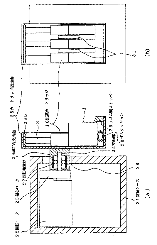
表2は、振騰速度を2800rpmとして振騰時間を5分、10分、15分としたとき、および振騰させずに15分間静置させたものの、Hpウレアーゼ濃度(mU/mL)に対するΔpHのデータの結果である。データは2回分の平均である。
【表2】
図7は、表2の結果をグラフにまとめたものである。これより、同じHpウレアーゼ濃度であれば静置よりも振騰させた方がΔpHは大きいこと、さらには振騰時間が長いほどΔpHが大きいことが示されている。
【0023】
以上の説明において、例えば測定対象をヘリコバクターピロリ由来ウレアーゼとすれば、固相部3aに固定化される抗体とは、ヘリコバクターピロリ由来ウレアーゼに対するモノクロナール抗体である。しかし、本発明はこれに限定されず、固相部3aに固定化される受容体は測定対象と特異的に結合し、測定対象は基質溶液のpHを変化させるものであれば良い。
【0024】
【発明の効果】
以上詳記したように、本試薬カートリッジの固相チップ3が検体希釈液収納部4の中に挿入された状態で振騰装置により振騰させるようにしたため、測定対象と受容体との結合反応速度を速めることができる。そのことにより同一の検出下限濃度を達成するための反応時間を短縮することができる。
【図面の簡単な説明】
【図1】本発明の実施の形態の試薬カートリッジの縦断面図。
【図2】本発明の実施の形態の試薬カートリッジの外観を示す斜視図。
【図3】本発明の実施の形態の試薬カートリッジにおける固相チップ3の外観を示す斜視図。
【図4】本発明の実施の形態の試薬カートリッジの使用状態を示す図。
【図5】本発明の試薬カートリッジを振騰装置に取り付けた状態を示す図であり、図5(a)は側面断面図、図5(b)は正面図。
【図6】本発明の実施の形態の試薬カートリッジにおける固相チップ3を用いて行ったpH誘因体測定を説明するための図。
【図7】Hpウレアーゼ濃度・振騰の有無・振騰時間がΔpHに与える影響をグラフにした図。
【符号の説明】
1 本体
2 固相チップ収納部
3 固相チップ
3a 固相部
3b 固相チップホルダー部
3c 貫通孔
4 検体希釈液収納部
5 検体希釈液
6 シール
10 試薬カートリッジ
11 測定セル
12 入口
13 オーバーフロー部
14 廃液口
15 pH電極
16 参照用pH電極
21 防振ケース
22 回転モーター
23 偏心ローター
24 支軸部
25 カートリッジ固定台
26 固定台支持部
27 回転軸受け
28 開口部
29a、29b ゴム製ストッパー
30 ゴムクッション
31 クッション[0001]
TECHNICAL FIELD OF THE INVENTION
TECHNICAL FIELD The present invention relates to a solid-phase chip type pH change inducer measurement method in which a reaction between an object to be measured and a receptor that specifically binds thereto is performed by a reagent cartridge.
[0002]
[Prior art]
BACKGROUND ART In biological fields such as medicine and biochemistry, there is a measuring device using a small-diameter tube solid phase in which a receptor for a substance to be measured is immobilized on an inner wall of a small-diameter tube as a measurement of a trace substance related to bioactivity ( For example, Patent Documents 1 and 2). In addition, the present applicant has proposed a reagent cartridge used for such a measuring device (Patent Document 3). Conventionally, in such a measuring apparatus, when the substance to be measured is adsorbed to the small-diameter tube solid phase, the small-diameter tube solid phase is simply immersed in the sample solution and allowed to stand. For example, in the reagent cartridge proposed in
[0003]
[Patent Document 1]
Patent No. 2591641 (General)
[Patent Document 2]
Patent No. 2634374 (General)
[Patent Document 3]
JP-A-11-174056 (general)
[0004]
However, since the solid-phase chip was inserted into the sample-diluting solution storage portion in which the sample was dissolved and allowed to stand, the speed of the ligand-receptor reaction was slow, and the measurement took time. There is also a demand for lowering the minimum lower limit value of the concentration at which the presence of the detection target can be confirmed as much as possible.
[0005]
[Problems to be solved by the invention]
The present invention has been made to solve such a problem, and its object is to promote the speed of the ligand-receptor reaction, to complete the measurement at an early stage, and to check the presence of the detection target. It is an object of the present invention to propose a measuring method for reducing the minimum lower limit of the concentration that can be confirmed.
[0006]
[Means for Solving the Problems]
In order to solve the above problems, a solid-phase chip-type pH change inducer measurement method using a reagent cartridge according to the present invention,
In the reagent cartridge, a solid-phase chip having a solid-phase part having a receptor specifically bound to an object to be measured immobilized on a surface thereof in a sample-diluent storage part containing a sample diluent, Is fixed so as to be immersed in the sample diluent, and the reagent cartridge is shaken at least in the axial direction of the solid phase portion.
By this method, the speed of the reaction between the object to be measured and the receptor that specifically binds thereto is increased.
[0007]
Further, by using the reagent cartridge in which the inner surface near the tip of the solid phase portion is tapered in a tapered shape, the reagent cartridge is swung at least in the axial direction of the solid phase portion, so that more reaction is caused. Speed will be increased.
[0008]
BEST MODE FOR CARRYING OUT THE INVENTION
FIG. 2 shows an overall appearance of the reagent cartridge according to the embodiment of the present invention, and FIG. 1 shows a longitudinal sectional view thereof. As shown in these figures, the main body 1 of the reagent cartridge has a solid-phase
[0009]
Hereinafter, each part will be described in detail. The sample diluent storage section 4 and the solid-phase
[0010]
FIG. 3 shows the appearance of the solid-
The inner surface of the vicinity of the tip of the
[0011]
The sample diluent 5 has a function of diluting samples such as blood, serum, lymph, gastric juice, gastric mucus, urine, etc., and ensuring a pH suitable for an antigen-antibody reaction described later. For this purpose, a pH buffer such as a phosphate buffer or a Tris buffer is usually used as the sample diluent. The
[0012]
Next, the
[0013]
In order to physically adsorb the antibody to the
[0014]
Next, a procedure for measuring the pH change inducer using the reagent cartridge configured as described above will be described. First, the operator peels off the
[0015]
Next, the
[0016]
An apparatus for shaking the reagent cartridge in a state where the solid-
As shown in FIG. 5A, a rotation motor 22 is built in the vibration isolating case 21 so that the eccentric rotor 23 is rotated. The eccentric rotor 23 is provided with a support shaft portion 24. On the other hand, a fixed base supporting part 26 is integrally formed with a cartridge fixing base 25 for standing and fixing the present reagent cartridge 10 in a state where the
As shown in FIG. 5B, three reagent cartridges 10 are arranged on the cartridge fixing stand 25 in an upright position, and a
[0017]
When the rotary motor 22 is driven in the state shown in FIG. 5, the eccentric rotor 23 rotates together with the support shaft 24. Along with this, the fixed base support part 26 that supports the support shaft part 24 via the rotary bearing 27 is also rotated, and the cartridge fixed base 25 is also rotated. At this time, the fixed base support part 26 supports the support shaft part 24 by the rotary bearing 27, and the center of gravity of the object composed of the reagent cartridge 10 and the cartridge fixed base 25 is below the support shaft part 24. The reagent cartridge 10 is shaken while maintaining the main body 1 on the upper side on the lower side. Accordingly, the solid-
[0018]
Since the inner surface of the vicinity of the tip of the
[0019]
FIG. 6 shows an apparatus for measuring a pH change inducer according to the method described in JP-A-10-332634. The measurement by this apparatus will be described. First, as shown in FIG. 6, the solid-
[0020]
Next, the effects of the swing speed and the shake time on the reaction speed will be described.
Table 1 shows that when the Hp urease concentration was fixed at 0.1 milliunit / mL, the shaking amplitude was 4 mm, the shaking time was 15 minutes, the sample solution was fixed at 70 μL, and the shaking speed was changed from 300 to 2800 rpm. 5 is an experimental result obtained by measuring ΔpH, which is a change in pH. The average value of two times is calculated.
Here, 1 millimeter unit is defined as the amount of urease that decomposes 1 μmol of urea per minute at 26 ° C.
As can be seen from Table 1, since the ΔpH increases as the rotation speed, which is the swing speed, increases, it can be seen that the reaction speed increases as the swing speed increases.
[Table 1]
Table 2 shows the ΔpH against the Hp urease concentration (mU / mL) when the shaking speed was 2800 rpm, the shaking time was 5 minutes, 10 minutes, and 15 minutes, and the sample was allowed to stand for 15 minutes without shaking. This is the result of the data. Data is the average of two runs.
[Table 2]
FIG. 7 is a graph summarizing the results of Table 2. This shows that, for the same Hp urease concentration, ΔpH is larger when shaken than when left still, and that ΔpH is larger as the shake time is longer.
[0023]
In the above description, for example, if the measurement target is Helicobacter pylori-derived urease, the antibody immobilized on the
[0024]
【The invention's effect】
As described in detail above, since the solid-
[Brief description of the drawings]
FIG. 1 is a longitudinal sectional view of a reagent cartridge according to an embodiment of the present invention.
FIG. 2 is a perspective view showing the appearance of the reagent cartridge according to the embodiment of the present invention.
FIG. 3 is a perspective view showing an appearance of a solid-
FIG. 4 is a diagram showing a usage state of the reagent cartridge according to the embodiment of the present invention.
5A and 5B are views showing a state where the reagent cartridge of the present invention is mounted on a shaking device, wherein FIG. 5A is a side sectional view and FIG. 5B is a front view.
FIG. 6 is a view for explaining a pH inducer measurement performed using the solid-
FIG. 7 is a graph showing the effects of Hp urease concentration, presence / absence of shaking, and shaking time on ΔpH.
[Explanation of symbols]
DESCRIPTION OF SYMBOLS 1
Claims (2)
前記試薬カートリッジを、少なくとも前記固相部の軸方向に振騰させることを特徴とする試薬カートリッジによる固相チップ方式pH変化誘因体測定方法。In the reagent cartridge, a solid phase chip having a solid phase portion having a receptor specifically bound to a measurement target immobilized on the surface thereof is provided in a sample diluent storage portion in which a sample diluent is stored. Is fixed so as to be immersed in the sample diluent,
A solid phase chip-type pH change inducer measuring method using a reagent cartridge, wherein the reagent cartridge is swung at least in the axial direction of the solid phase portion.
Priority Applications (1)
| Application Number | Priority Date | Filing Date | Title |
|---|---|---|---|
| JP2003016268A JP2004226307A (en) | 2003-01-24 | 2003-01-24 | Solid-phase chip-type pH change trigger measurement method using reagent cartridge |
Applications Claiming Priority (1)
| Application Number | Priority Date | Filing Date | Title |
|---|---|---|---|
| JP2003016268A JP2004226307A (en) | 2003-01-24 | 2003-01-24 | Solid-phase chip-type pH change trigger measurement method using reagent cartridge |
Publications (1)
| Publication Number | Publication Date |
|---|---|
| JP2004226307A true JP2004226307A (en) | 2004-08-12 |
Family
ID=32903782
Family Applications (1)
| Application Number | Title | Priority Date | Filing Date |
|---|---|---|---|
| JP2003016268A Pending JP2004226307A (en) | 2003-01-24 | 2003-01-24 | Solid-phase chip-type pH change trigger measurement method using reagent cartridge |
Country Status (1)
| Country | Link |
|---|---|
| JP (1) | JP2004226307A (en) |
Cited By (1)
| Publication number | Priority date | Publication date | Assignee | Title |
|---|---|---|---|---|
| JP2015514992A (en) * | 2012-04-16 | 2015-05-21 | アクセス メディカル システムズ,リミティド | Extensive luminescent immunoassay |
-
2003
- 2003-01-24 JP JP2003016268A patent/JP2004226307A/en active Pending
Cited By (2)
| Publication number | Priority date | Publication date | Assignee | Title |
|---|---|---|---|---|
| JP2015514992A (en) * | 2012-04-16 | 2015-05-21 | アクセス メディカル システムズ,リミティド | Extensive luminescent immunoassay |
| US10451616B2 (en) | 2012-04-16 | 2019-10-22 | Access Medical Systems, Ltd. | Wide range luminescent immunoassays |
Similar Documents
| Publication | Publication Date | Title |
|---|---|---|
| ES2312763T3 (en) | APPARATUS AND METHODS FOR MEASURING ANALYTES AND IMMUNOENSAY. | |
| US9737890B2 (en) | Microfluidic device and method for operating thereof | |
| ES2820877T3 (en) | Improvement of the interference of a heterophile antibody in an immunosensor | |
| KR102418162B1 (en) | Sample containers adapted for acoustic ejections and sample preservation and methods thereof | |
| ES2241911T3 (en) | DEVICE AND TEST PROCEDURE FOR HIGH DENSITY LIPOPROTEINS. | |
| JP4523598B2 (en) | Liquid router | |
| JP2009545741A (en) | Immunochromatographic strip and kit containing the same | |
| PT1390760E (en) | Assay system | |
| CN1452718A (en) | Analyzing device | |
| CN1904620A (en) | Chemical analysis device | |
| CN1800858A (en) | Chemical analysis apparatus and chemical analysis cartridge | |
| CN1755370A (en) | Chemical analysis device and structure used therein | |
| WO2007105764A1 (en) | Disk for liquid sample analysis | |
| CN110023757A (en) | The device and method for reducing the interfering compound in biological sample | |
| WO2014150876A2 (en) | Biosensor structures for improved point of care testing and methods of manufacture thereof | |
| CN110694700A (en) | two-part assembly | |
| JPH05307038A (en) | Method for preserving antigen cell in solid phase immunity inspection | |
| HU223618B1 (en) | Process and process fluid processing | |
| JP2009168585A (en) | Sample solution analysis method and sample solution analyzer | |
| ES3035098T3 (en) | Biochemical reaction substrate and analysis device | |
| JP2004226307A (en) | Solid-phase chip-type pH change trigger measurement method using reagent cartridge | |
| CN111630394A (en) | Subject measurement device, reagent container, and subject measurement method | |
| US7381374B2 (en) | Immunoassay devices and methods of using same | |
| KR20200001389A (en) | System and method for detecting immunodiagnostic biomarker using magnetic particles and electrochemical sensor | |
| JP6190472B2 (en) | Novel PoC inspection system and method |
Legal Events
| Date | Code | Title | Description |
|---|---|---|---|
| A621 | Written request for application examination |
Free format text: JAPANESE INTERMEDIATE CODE: A621 Effective date: 20050920 |
|
| A977 | Report on retrieval |
Free format text: JAPANESE INTERMEDIATE CODE: A971007 Effective date: 20071023 |
|
| A131 | Notification of reasons for refusal |
Free format text: JAPANESE INTERMEDIATE CODE: A131 Effective date: 20071113 |
|
| A02 | Decision of refusal |
Free format text: JAPANESE INTERMEDIATE CODE: A02 Effective date: 20080415 |