JP2004209096A - Medical instrument holding device - Google Patents
Medical instrument holding device Download PDFInfo
- Publication number
- JP2004209096A JP2004209096A JP2003001461A JP2003001461A JP2004209096A JP 2004209096 A JP2004209096 A JP 2004209096A JP 2003001461 A JP2003001461 A JP 2003001461A JP 2003001461 A JP2003001461 A JP 2003001461A JP 2004209096 A JP2004209096 A JP 2004209096A
- Authority
- JP
- Japan
- Prior art keywords
- arm
- endoscope
- holding
- weight
- medical device
- Prior art date
- Legal status (The legal status is an assumption and is not a legal conclusion. Google has not performed a legal analysis and makes no representation as to the accuracy of the status listed.)
- Pending
Links
- 230000005484 gravity Effects 0.000 description 23
- 230000003287 optical effect Effects 0.000 description 11
- 238000010586 diagram Methods 0.000 description 8
- 210000003811 finger Anatomy 0.000 description 7
- 230000000694 effects Effects 0.000 description 6
- 238000006243 chemical reaction Methods 0.000 description 5
- 238000001514 detection method Methods 0.000 description 4
- 230000003028 elevating effect Effects 0.000 description 4
- 238000003780 insertion Methods 0.000 description 4
- 230000037431 insertion Effects 0.000 description 4
- 210000003813 thumb Anatomy 0.000 description 4
- 210000003625 skull Anatomy 0.000 description 3
- 238000013459 approach Methods 0.000 description 2
- 230000014509 gene expression Effects 0.000 description 2
- 238000000034 method Methods 0.000 description 2
- 238000012986 modification Methods 0.000 description 2
- 230000004048 modification Effects 0.000 description 2
- 230000001105 regulatory effect Effects 0.000 description 2
- 125000002066 L-histidyl group Chemical group [H]N1C([H])=NC(C([H])([H])[C@](C(=O)[*])([H])N([H])[H])=C1[H] 0.000 description 1
- 206010028980 Neoplasm Diseases 0.000 description 1
- 238000005452 bending Methods 0.000 description 1
- 210000004204 blood vessel Anatomy 0.000 description 1
- 230000001276 controlling effect Effects 0.000 description 1
- 238000012937 correction Methods 0.000 description 1
- 238000006073 displacement reaction Methods 0.000 description 1
- 238000002406 microsurgery Methods 0.000 description 1
- 238000012283 microsurgical operation Methods 0.000 description 1
- 210000005036 nerve Anatomy 0.000 description 1
- 210000001519 tissue Anatomy 0.000 description 1
Images


Classifications
-
- A—HUMAN NECESSITIES
- A61—MEDICAL OR VETERINARY SCIENCE; HYGIENE
- A61B—DIAGNOSIS; SURGERY; IDENTIFICATION
- A61B90/00—Instruments, implements or accessories specially adapted for surgery or diagnosis and not covered by any of the groups A61B1/00 - A61B50/00, e.g. for luxation treatment or for protecting wound edges
- A61B90/50—Supports for surgical instruments, e.g. articulated arms
- A61B2090/5025—Supports for surgical instruments, e.g. articulated arms with a counter-balancing mechanism
- A61B2090/504—Supports for surgical instruments, e.g. articulated arms with a counter-balancing mechanism with a counterweight
Landscapes
- Health & Medical Sciences (AREA)
- Surgery (AREA)
- Life Sciences & Earth Sciences (AREA)
- Heart & Thoracic Surgery (AREA)
- Molecular Biology (AREA)
- Oral & Maxillofacial Surgery (AREA)
- Engineering & Computer Science (AREA)
- Biomedical Technology (AREA)
- Nuclear Medicine, Radiotherapy & Molecular Imaging (AREA)
- Medical Informatics (AREA)
- Pathology (AREA)
- Animal Behavior & Ethology (AREA)
- General Health & Medical Sciences (AREA)
- Public Health (AREA)
- Veterinary Medicine (AREA)
- Endoscopes (AREA)
- Manipulator (AREA)
- Accommodation For Nursing Or Treatment Tables (AREA)
Abstract
Description
【0001】
【発明の属する技術分野】
本発明は、例えば脳神経外科等の腫瘍摘出術で使用される内視鏡や処置具等の医療用器具を保持する医療用器具保持装置に関する。
【0002】
【従来の技術】
近年、脳神経外科手術において微細な術部の拡大観察を行なうために手術用顕微鏡が使用されてマイクロサージャリーが頻繁に行われている。手術用顕微鏡の観察範囲は頭蓋の開創部を通して観察できる範囲に限られており、手術用顕微鏡では見えない死角部分がある。このため、手術用顕微鏡では見えない死角部分を観察するために内視鏡が用いられる。
【0003】
そして、内視鏡観察像を見ながら頭蓋内の治療部位に処置具を挿入してマイクロサージャリーが行なわれる。その際、内視鏡は複数のアームと関節部を備えた医療用器具保持装置により、固定・支持された状態で使用される。ところで、頭蓋内は神経、血管等の重要組織が複雑かつ微細に絡み合って構成されている。このため、医療用器具保持装置によって内視鏡を微細かつスムーズに移動したり、正確な位置に内視鏡を固定したりすることができる構成であることが望まれている。
【0004】
例えば特許文献1は、先端部に内視鏡等の医療用器具を保持する保持部を配した医療用器具保持装置について開示されている。この装置は複数のアームの関節部に球面継手を配設し、また、医療用器具を保持する先端部の反対側に医療用器具などの重量に釣り合わせるようにカウンターバランス(カウンターウェイト)を設けている。このため、医療用器具を軽い力で自由に配置させることを可能としている。また、この装置では、そのアームの関節を例えば人間の関節の動きと同等の動きが可能である球面継手を用いて構成している。このため、球面継手を介して保持部に取り付けられた医療用器具を自然な操作感をもって操作することが可能となる。さらに、術式や術部に応じて医療用器具を最適に配置することが可能となる。
【0005】
また、例えば特許文献2は各アームを平行四辺形リンクで構成した医療用器具保持装置について開示されている。この装置は、本体支持部の先端部に取り付けられる医療用器具の重心をアーム先端部のL字型の俯仰中心に一致させている。また、本体支持部の医療用器具が配設された側に対して反対側に医療用器具等の重量を相殺する2つのカウンターバランスを備えている。このため、常にバランスが取れた状態で医療用器具を自由に移動させて配置することが可能となっている。そして、このような装置では、平行四辺形リンクからなる本体支持部に設けられたカウンターバランス型アームにより、支持部の先端部に取り付けられた医療用器具を常にバランスを保った状態で移動操作することが可能である。このため、術者は内視鏡の観察視野の変更等、微妙な調整も容易に行なうことができる。
【0006】
【特許文献1】
特開平8−52158号公報
【0007】
【特許文献2】
特開平7−227398号公報
【0008】
【発明が解決しようとする課題】
例えば特許文献1に開示された医療用器具保持装置では、その関節の動きによって、本体支持部に対するアームの先端部や各アーム本体、さらには、その先端部に取り付けられた重量物である医療用器具の位置が変化する。このため、カウンターバランスにより常に完全なバランスを取ることは難しい。したがって、球面継手により構成されている各関節の固定を解除すると、アーム本体や医療用器具の重量によって医療用器具が術者の意図しない方向に動いてしまうことがある。特に内視鏡のような医療用器具を術部に挿入した状態で観察視野を微妙に調整する場合などには術者は細心の注意が必要となり、多大な疲労を与えることとなっていた。
【0009】
また、例えば特許文献2に開示された医療用器具保持装置では、内視鏡を微妙に傾斜させる俯仰機構をその俯仰中心と内視鏡の重心とを平行四辺形リンクを構成するアーム上で一致させるように配置する必要がある。すなわち、内視鏡の把持部に俯仰機構を配置することが必要となり、内視鏡の把持部近傍が非常に大型化する。したがって、術部を処置する際に処置具などを挿入する空間が減ってしまい、処置具操作の自由度が減るといった問題が発生する。例えば内視鏡を手術用顕微鏡と合わせて用い、手術用顕微鏡の死角部位を内視鏡で観察する。このような場合には、把持部が大型化することにより内視鏡と手術用顕微鏡の鏡体部が干渉しやすくなり、手術作業の制限が大きくなってしまうという問題があった。
【0010】
本発明は、このような課題を解決するためになされたものであり、術部の観察や処置を行なう医療用器具の手術作業空間に与える制限を最小に抑え、医療用器具を容易かつ確実に移動、配置、固定することができ、医療用器具の例えば細かい操作などを安定的に行なうことが可能な医療用器具保持装置を提供することが目的である。
【0011】
【課題を解決するための手段】
上記課題を解決するために、この発明の医療用器具保持装置は、医療用器具を保持する保持手段と、この保持手段を傾斜可能に支持する傾斜支持機構と、2つの端部を有し、その一方の端部で前記傾斜支持機構を支持する支持手段と、2つの端部と、これら端部間に設けられた枢軸とを有し、一方の端部で前記支持手段の他方の端部を支持するとともに、前記枢軸を中心として回動して前記支持手段を移動させる回動部材を含み、所定の範囲内で前記傾斜支持機構および保持手段を移動させて前記医療用器具を所望の位置に移動させる移動手段と、この移動手段の他方の端部に支持され、前記医療用器具を保持する保持手段の重量によって生じる前記枢軸周りの回転モーメントよりも小さい前記枢軸周りの回転モーメントを発生させる重量を有するカウンターウェイトとを備えている。
【0012】
このため、把持される医療用器具周辺の小型化により広い手術作業空間が確保される。また、装置に取り付けられる医療用器具のような重量物のバランスが保たれた状態で移動操作して確実に所望の位置に配置されて固定される。
【0013】
【発明の実施の形態】
以下、図面を参照しながらこの発明の好ましい実施の形態について説明する。
【0014】
(第1の実施の形態)
まず、第1の実施の形態について図1および図2を用いて説明する。
図1に示すように、この実施の形態に係わる医療用器具保持装置100は、手術台3aに設けられたサイドレール3に沿って移動可能で、例えば固定ねじ4によって所望の位置で固定可能なベース部2を備えている。図1および図2に示すように、このベース部2には、軸受部2aが設けられ、この軸受部2aでベース部2に対して例えば鉛直軸O1回りに回動自在な支持アーム1の下端が支持されている。この支持アーム1の上端には軸受部(支持部)5が設けられている。この軸受部5には、鉛直軸O1に対して直交する方向に回動軸(枢軸)O2が設けられ、この回動軸O2回りに回動(揺動)自在な回動部材としてアーム6aが装着されている。このアーム6aの一端には軸受部7が、他端には軸受部8がそれぞれ設けられており、これら軸受部7,8を挿通する互いに平行な軸O3回りに回動可能にそれぞれアーム6c,6dが接続されている。なお、軸受部5は、アーム6aの略中央に設けられていることが好適であるが、アーム6aの両端および両端の間のいずれの位置に設けられていてもよい。
【0015】
さらに、それぞれアーム6c,6dの他端側、他端には、軸受部9,10が設けられている。これら軸受部9,10には、軸受部9,10を挿通する軸O3回りに回動可能、かつ、アーム6aに対して平行にアーム6bが連接されている。したがって、これら4つのアーム6a−6dと4つの軸受部7−10とにより医療用器具保持装置100の平衡手段に相当する平行四辺形リンク機構6が構成されている。なお、アーム6cはアーム6dよりも長尺に形成され、その他端は平行四辺形リンク機構6の外部に延出されている。また、アーム6a,6bはそれぞれ軸受部7,9に接続されたアーム6cの軸受部7,9間よりも長尺に形成されていることが好適である。すなわち、アーム6a,6bはアーム6dよりも長尺に形成されていることが好適である。
【0016】
そして、この平行四辺形リンク機構6の1つの軸受部8には、さらに軸受部8の軸O3に対して直交した軸O4を有する軸受部12が配設されている。この軸受部12には医療用器具の支持手段として長尺の支持アーム11の一端(基端)が支持され、支持アーム11の一端とアーム6dとが連接されている。このため、支持アーム11とアーム6dとは、軸O4上の同一軸上に配設されていることが好適である。この支持アーム11の他端(先端)には、図1中に矢印13,14で示す前後左右方向に俯仰可能(傾斜可能)に支持する傾斜支持機構であるボールジョイント15によって医療用器具を保持する保持手段が支持されている。この実施の形態では、保持手段として保持アーム16が支持されている。この保持アーム16には、医療用器具として例えば内視鏡17が一体的に取り付けられている。さらに、この内視鏡17にはその観察像を撮像するテレビカメラ18が光学的に接続されている。そして、このテレビカメラ18は図示しないカメラ制御ユニットに、このカメラ制御ユニットは図示しないTVモニターに電気的にそれぞれ接続されている。
【0017】
一方、上述した軸受部8に対して対角上の軸受部9よりも外方に延出されたアーム6cの他端にはカウンターウェイト(カウンターバランス)19が一体的に取り付けられている。このカウンターウェイト19は、保持アーム16、内視鏡17およびテレビカメラ18等を主としてまとめた重量物による軸O2回りに発生する慣性(回転)モーメントを相殺するべく、任意の重量を備えている。なお、このカウンターウェイト19は着脱可能であり、かつ、その重量が上述した重量物や軸O2までの距離によって適宜に選択可能であることが好適である。
【0018】
さらに、上述した軸受部2aには、ベース部2に対する支持アーム1の軸O1回りの回動を電気的に規制する例えば電磁ブレーキ(電磁クラッチ)20が配設されている。また、軸受部5にはアーム6aの軸O2回りの回動を電気的に規制する電磁ブレーキ21が、軸受部8にはアーム6dの軸O3回りの回動を規制する電磁ブレーキ22が、軸受部12には支持アーム11の軸O4回りの回動を電気的に規制する電磁ブレーキ23が、さらに、ボールジョイント15内にも保持アーム16の矢印13,14方向の俯仰を電気的に規制する電磁ブレーキ24がそれぞれ設けられている。また、保持アーム16には、押圧するとこれら電磁ブレーキ20−24のブレーキ動作を固定状態から固定解除状態に切り替える入力切替手段として入力スイッチ25が配設されている。そして、この入力スイッチ25は、押圧によって発生した信号を制御する制御手段として制御回路(図示せず)に接続されている。
【0019】
したがって、平行四辺形リンク機構6は、電磁ブレーキ20−24が固定解除状態である場合において、保持アーム16、ボールジョイント15、支持アーム11を所定の範囲内で移動させることができるようになっている。このため、平行四辺形リンク機構6は、保持アーム16の先端に配設された内視鏡17を所定の範囲内で移動させる移動手段として形成されている。
【0020】
なお、図1および図2中の符号Gは、上述したように、ボールジョイント15を介して支持アーム11によって支持される医療用器具保持アーム16、内視鏡17、テレビカメラ18を主としてまとめた重量物の重心位置を示している。符号G’は上述したカウンターウェイト19の重心位置を示している。符号Pは、術者が内視鏡17を移動操作する際に内視鏡17を把持する把持部の中心、すなわち、作用点(操作点)を示している。
【0021】
次に、図2を用いて重量物である医療用器具保持アーム16、内視鏡17、テレビカメラ18等に対するカウンターウェイト19の重量について、つまりバランスの取り方について説明する。なお、平行四辺形リンク機構6を構成するアーム6a−6dおよび支持アーム11の重量は、医療用器具保持アーム16、内視鏡17、テレビカメラ18等の重量物およびカウンターウェイト19の重量に比べて十分に小さい。このため、アーム6a−6dおよび支持アーム11の重量を無視、すなわち重量がないものと仮定して説明する。
【0022】
上述した重量物の重心Gでの重量をWg、この重量物の重心Gから軸受部5の回動軸O2に直交する回動軸O1までの距離をLgとすると、重心Gにおいて回動軸O2回りに発生する回転モーメントMgは、
Mg=Wg・Lg …(1)
となる。また、術者が内視鏡17を移動操作する際に内視鏡17を把持する把持部の中心を作用点Pとすると、内視鏡17の操作時には重心Gにかかる重量Wgの一部が術者によって保持される。このため、保持された状態でのボールジョイント15にかかる重量をW1、術者による保持力量(操作力量)をW2’とすると、
Wg=W1−W2’ …(2)
となる。そして、作用点Pにかかる重量W2を保持力量W2’の反力(W2=−W2’)として考えると、式(2)は、
Wg=W1+W2 …(3)
となる。
【0023】
ここで、ボールジョイント15の中心から上述した重心Gまでの距離をS1、重心Gから作用点Pまでの距離をS2とする。すなわち、内視鏡17の作用点(操作点)Pとボールジョイント15の左右前後方向の傾斜の中心との間の距離をS1+S2だけ離れた状態にあるとする。このとき、重心Gの回りに発生する慣性モーメントの関係から
W2=(S1/S2)・W1 …(4)
となるので、式(3),(4)より
W1=(S2/(S1+S2))・Wg …(5)
となる。
【0024】
ここで、ボールジョイント15の中心において軸受部5の回動軸O2回りに発生する慣性モーメントMwは、
Mw=W1・Lw …(6)
となる。
【0025】
これに対してカウンターウェイト19によって発生する回動軸O2回りの回転モーメントMcはカウンターウェイト19の重量をWc、カウンターウェイト19の重心G’から回動軸O1,O2までの距離をLcとすると
Mc=Wc・Lc …(7)
となる。ここで、この実施の形態においてカウンターウェイト19の重量Wcは上述のモーメントMwを相殺する重量に設定されている。このため、Mw=Mcの関係が得られ、式(6),(7)よりカウンターウェイト19の重量Wcは、
Wc=(Lw/Lc)・(S2/(S1+S2))・Wg …(8)
となる。すなわち、このような関係が成り立つように距離および重量が設定されている。
【0026】
ここで、例えば回転軸O2との距離が距離Lw:Lc=2:1、かつ、重心Gからの距離S1:S2=1:1に形成されているとする。すなわち、アーム6a−6d、支持アーム11および保持アーム16がこのような関係を満たすように形成されているとする。すると、カウンターウェイト19の重量Wcと重量物の重量Wgとの関係は、
Wc=Wg …(9)
となる。このため、Lw=Lg=2とすると、カウンターウェイト19によって発生する回動軸O2回りの回転モーメントMc、および、重量物の重心Gの位置に発生する回動軸O2回りの回転モーメントMgは、それぞれ
Mc=Wg・Lc=Wg …(10)
Mg=Wg・Lg=2Wg …(11)
となる。したがって、式(10),(11)により、カウンターウェイト19によって発生する回動軸O2回りの回転モーメントMcと、重心Gにおいて回動軸O2回りに発生する回転モーメントMgとの関係は、
Mc=(1/2)Mg
となる。したがって、このようなモーメントの関係が成り立つように、距離Lw,Lc,S1,S2および重量Wc,Wgが設定されてカウンターウェイト19と重量物とのバランスが図られている。
【0027】
次に、このような構成を有する医療用器具保持装置100の作用について説明する。
例えば内視鏡17を術部Xに挿入して術部Xの内部観察をするために、術者は内視鏡17を手で把持した状態で保持アーム16に設けられた入力スイッチ25を把持した手の指で押圧する(図1参照)。すると、図示しない制御回路により、電磁ブレーキ20−24のブレーキ状態がそれぞれ解除され、回動軸O1回りに支持アーム1が回転可能となる。また、回動軸O2回りにアーム6aが回動可能になることにより、平行四辺形リンク機構6全体が回転軸O1回りに傾斜する。さらに、軸受部8の回動軸O3回りにアーム6dが回動可能となることにより、平行四辺形リンク機構6が変形され、支持アーム11の進退動が可能となる。また、回動軸O4回りに支持アーム11が回転可能となるとともに、ボールジョイント15によって保持アーム16の矢印13,14の方向の俯仰が可能となる。このため、術者は内視鏡17の先端部を3次元的に自由な位置に配置可能となる。
【0028】
このとき、術者は内視鏡17の作用点Pを手で把持した状態で、内視鏡17を移動操作する。すると、保持アーム16、内視鏡17、テレビカメラ18等を含めた重量物の重量Wgによりボールジョイント15の中心回りに回転モーメントMpが発生する。このため、術者の手にはアンバランス力量として、重量Wgの一部分である重量W2が働く。すなわち、術者はそのアンバランス力量を手で支えるために反力W2’を作用点Pで重量W2の反対方向に働かせる。したがって、重量W2と反力W2’とは互いに打ち消しあう関係にある(W2=W2’)ので、ボールジョイント15にかかる重量W1は、W1=Wg−W2+W2’=Wgとなる。このため、回動軸O2回りに発生する回転モーメントはボールジョイント15にかかる重量W1のみに影響される(Wg=W1)。したがって、ボールジョイント15の中心において回動軸O2回りに発生する慣性モーメントMwは、上述した式(6)と同一となる。
【0029】
ここで、カウンターウェイト19による回動軸O2回りの回転モーメントMcはモーメントMwを打ち消す回転モーメントを発生させる重量に設定されている(Mc=Mw)。すなわち、術者は平行四辺形リンク機構6および支持アーム11を上述した式(8)の関係を満たすように設定している。そして、このように装置100のバランスを取った状態で内視鏡17を所望の位置に向けて操作して、内視鏡17を所望の位置に配置する。このとき、装置100のバランスを取っているので、術者は軽い力で内視鏡17を所望の位置、所望の方向に移動して配置することができる。
【0030】
術者は内視鏡17を所望の位置に配置した後、入力スイッチ25から指を離すことで電磁ブレーキ20−24によってそれぞれの軸受部2a,5,8,15が固定される。このため、内視鏡17はその位置でしっかりと固定される。内視鏡17の図示しない光学系でリレーされた術部Xの観察像は、テレビカメラ18によって撮像された後、図示しないTVコントロールユニットを介してモニター上に表示され、術者によって観察される。
【0031】
以上説明したように、この実施の形態によれば以下のような効果が得られる。内視鏡17を前後左右方向に俯仰させるボールジョイント部15と内視鏡17の操作点Pとをずらして配置した。このため、保持アーム16で保持される内視鏡17の把持部、すなわち操作部は通常の内視鏡17と略同等の接眼レンズおよびTVカメラ程度の大きさで済む。すなわち、ボールジョイント部15と干渉することがないので余分な装置を設ける必要がない。したがって、医療用器具保持アーム16を使用しない場合、つまり、支持アーム11に医療用器具17が直接連接されている場合と略同等の作業空間を確保することができる。
【0032】
また、ボールジョイント15回りに発生するアンバランス力量を差し引いた分の重量に釣り合うように平行四辺形リンク機構6にカウンターウェイト19を設定した。このため、術者は支持アーム11の先端の関節(ボールジョイント15)の先端側にかかるアンバランス力量分、すなわち作用点Pにかかる重量W2を反力W2’で支えることのみによって装置100のバランスが図られる。したがって、内視鏡17を所望の位置に軽い力で自由に配置することができる。
【0033】
さらに、支持アーム11は、関節(ボールジョイント15)を介して保持アーム16のみを支えている。このため、そのアンバランス力量によって生じる力の方向は保持アーム16および医療用器具17の重量がかかる方向、すなわち例えば鉛直方向などの単一方向に定まる。したがって、電磁ブレーキ20−24を解除しても術者の意図しない方向にアームが移動し難くなる。例えば医療用器具17を細かく操作するときに安定的に行なうことができる。
【0034】
以上説明したように、術部の観察や処置を行なう医療用器具17の手術作業空間に与える制限を最小に抑え、医療用器具17を容易かつ確実に移動、配置、固定することができ、医療用器具の例えば細かい操作などを安定的に行なうことが可能な医療用器具保持装置100を提供することができる。
【0035】
なお、この実施の形態においては医療用器具として内視鏡17を例として説明したが、鉗子や切子などの処置具であっても同様の効果が得られることは言うまでもない。
【0036】
(第2の実施の形態)
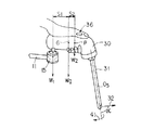
次に、図3ないし図5に従って第2の実施の形態について説明する。この実施の形態は第1の実施の形態の変形例である。このため、第1の実施の形態で説明した部材と同一の部材には同一の符号を付し、ここでの説明を省略する。ここでは、保持手段として保持アーム16の代わりにグリップ30が設けられ、また、装着されたカウンターウェイト19の代わりにカウンターウェイト調整機構としてカウンターウェイト38が設けられている。
【0037】
図3ないし図5に示すように、支持アーム11の先端に設けられたボールジョイント15には、第1の実施の形態で用いた保持アーム16の代わりに、医療用器具を保持するグリップ30が回動可能に取り付けられている。このグリップ30は、ボールジョイント15に回動可能に取り付けられた本体部と、この本体部に対して適当な角度に屈曲するとともに、医療用器具として例えば内視鏡31を先端に保持している屈曲部とを備えている。この内視鏡31はその挿入軸O5回りに回動可能に保持されている。そして、図3および図4に示すように、この内視鏡31は、その先端部に挿入軸O5に対してある一定の角度αの観察光軸32を有する、いわゆる斜視型(側視型)に形成されている。この内視鏡31の挿入軸O5の内部には、図示しない対物レンズやリレー光学系等が内蔵されている。
【0038】
一方、グリップ30の内部には、図3に示すようにリレー光学系34と反射部材33とを備え、内視鏡31の内部のリレー光学系と光学的に接続されている。さらに、グリップ30の内部には、グリップ30の内部のリレー光学系34によってその撮像素子上に内視鏡31の観察像を結像するTVカメラ35が配置されて固定されている。また、グリップ30の上面には、電磁ブレーキ20−24の固定/解除の入力切り替えを行なうスイッチ36が設けられている。このスイッチ36は、図示しない制御回路に接続されている。
【0039】
さらに、平行四辺形リンク機構6を構成するアーム6cのリンク機構6の外側に延設された他端側には同軸上にリードネジ37が一体的に形成されている。このリードネジ37にはカウンターウェイト38が矢印39方向に回転しながら移動可能、すなわち軸O2回りの回転モーメント量が可変状態に螺着されている。
【0040】
次に、このような構成を有する医療用器具保持装置100の作用について説明する。
術者は、グリップ30の本体部の前方側を観察する場合、例えば図4に示すようにグリップ30を把持する。例えば親指でスイッチ36を押圧するとともに、人差指をグリップ30の本体部と屈曲部との境界周辺に配置する。このとき、内視鏡31およびグリップ30とからなる重量物の重心G、ボールジョイント15の中心、および、術者がグリップ30を把持する際の作用点Pの位置関係は図4に示されている。すなわち、グリップ30の前方側を観察する場合、手の前方側に屈曲部および内視鏡31が配設されるようにスイッチ36を押圧した状態であり、重量物の重心位置Gが作用点P側に偏って位置している。なお、作用点Pは、グリップ30を把持した状態の親指と他の指との略中央部分に位置している。また、距離S1は、重心位置Gからボールジョイント部15までの距離であり、距離S2は、重心位置Gから作用点Pまでの距離である。
【0041】
術者がグリップ30に設けられたスイッチ36を押圧操作すると、電磁ブレーキ20−24が解除される。すると、第1の実施の形態と同様に、図3に示す平行四辺形リンク機構6および支持アーム11、さらにカウンターウェイト38によってボールジョイント15にかかる重量W1による軸O2回りの回転モーメントが相殺される。このため、術者は軽い力量で内視鏡31を所望の位置に移動できる。
【0042】
次に、スイッチ36から指を離すことにより、電磁ブレーキ20−24が固定される。内視鏡31の対物レンズに入射された光は、内視鏡31の図示しないリレー光学系、グリップ30の反射部材33およびリレー光学系34を介してTVカメラ35の撮像素子上に結像される。そして、図示しないモニター上にその観察像として映し出される。また、このとき、図4に示す距離S1,S2の関係をS1:S2=2:1であると仮定すると、ボールジョイント15にかかる重量W1は上述した式(5)より
W1=Wg/3 …(12)
となる。
【0043】
次に、術者が内視鏡31よって異なる斜視の方向を観察する際、例えば、図4と180°逆の方向、すなわち図5に示すような観察を行なう場合について説明する。この場合、まず、内視鏡31をその挿入軸O5回りに矢印41方向(図4参照)に180°回転させる。そして、術者はグリップ30を図5に示すように、図4に示す方向に対して逆方向から把持する。すなわち、例えば親指でスイッチ36を押圧するとともに、人差指を本体部と屈曲部との境界周辺に配置する。つまり、手の前方側は、グリップ30の本体部の基端側、ボールジョイント15側に向けられている。このとき、内視鏡31およびグリップ30とからなる重量物の重心G、ボールジョイント15の中心、および、術者がグリップ30を把持する際の作用点Pの位置関係は図5に示されている。すなわち、グリップ30の後方側を観察する場合、手の後方側に内視鏡31が配設されるように、スイッチ36を押圧した状態で重量物の重心位置Gがグリップ30の本体部の略中央部近傍に位置している。なお、作用点Pは、グリップ30を把持した状態の親指と他の指との略中央部分に位置している。
【0044】
そして、上述したように術者がグリップ30に設けられたスイッチ36を押圧操作すると、電磁ブレーキ20−24が解除される。すると、第1の実施の形態と同様に、図3に示す平行四辺形リンク機構6および支持アーム11、さらにカウンターウェイト38によってボールジョイント15にかかる重量W1による軸O2回りの回転モーメントが相殺される。このため、術者は軽い力量で内視鏡31を所望の位置に移動できる。
【0045】
このとき、図5に示す距離S1,S2の関係をS1:S2=1:1と仮定すると、上述したようにボールジョイント15にかかる重量W1は式(5)より
W1=Wg/2 …(13)
となる。ここで、式(12),(13)を比較すると、グリップ30の把持の仕方によって上述した重量W1の値が変化することが認識される。
【0046】
そこで、図3に示すように、術者はカウンターウェイト38をその中心軸回りである矢印42の方向に回転させる。すると、リードネジ37によってカウンターウェイト38は回転しながら矢印39方向、すなわちアーム6cの軸方向に沿って移動する。例えば、上述したように重量W1がWg/3(式(12)参照)からWg/2(式(13)参照)のように増加した場合には、カウンターウェイト38の効きを強くさせる必要がある。このため、重量W1に対するバランス状態を確保するまで、カウンターウェイト38を平行四辺形リンク機構6から離れる方向に回転させてバランスを取るように移動させる。
【0047】
以上説明したように、この実施の形態によれば、第1の実施の形態で説明した効果に加えて以下のような効果が得られる。
グリップ30の把持方法、把持位置によって変化する操作点Pの位置ずれによって発生するアンバランス力量に対して、カウンターウェイト38をアーム6cの軸方向に沿って移動させることによって簡単に補正することができる。このため、より確実で容易な内視鏡31の操作が可能となる。
【0048】
さらに、内視鏡31の観察像を撮像するTVカメラ35やリレー光学系34をグリップ30内に内蔵している。また、このグリップ30は一般にボールジョイント15を介して支持アーム11から回動可能に延出されている。このため、内視鏡31の把持部周辺に余計な部材を配置することなく小型化することができる。そして、内視鏡31の観察下での術部の処置作業空間をさらに広く確保できる。
【0049】
また、この実施の形態ではグリップ30の内部に通常は観察光軸方向に突出する例えばTVカメラ35等が内蔵されているので、観察光軸方向への突出を極端に小さくすることができる。このため、手術用顕微鏡(図示せず)と内視鏡31とを組合せて使用する際にも、さらに内視鏡31が邪魔になり難く、操作性を向上させることができる。したがって、術部のより確実な処置作業が可能となる。
【0050】
(第3実施の形態)
続いて、図6ないし図9に従い第3の実施の形態を説明する。この実施の形態は第2の実施の形態の変形例であって、同一の部材には同一の符号を付し、詳しい説明を省略する。そして、この実施の形態では第2の実施の形態で説明したボールジョイント15が自在ジョイント49に変更され、また、カウンターウェイト38の調整機構が変更されている。以下、異なる部分のみ説明する。
【0051】
まず、図6および図7を用いて自在ジョイント49の構成について説明する。図6および図7に示すように、支持アーム11の他端には、例えばコ字状やU字状などに形成された軸受部50が接続されている。この軸受部50の内側部には、円弧状または球面状の支持部56が形成されている。そして、この支持部56に対して摺動するように、すなわち、図7中の矢印57の方向に揺動可能(傾斜可能)に支持するように、両端部が例えば半球状や円弧形状などに形成されている軸51が支持されている。さらに、この軸51は中央部に回転盤52を備え、この軸51の中心軸O11を枢軸として図6中の矢印54の方向に回動可能となっている。
【0052】
この回転盤52の外周には、例えば軸O11に対して直交する方向に軸を有する支持部材53の一端が一体的に配設されている。この支持部材53の他端には、図示しないが上述したグリップ30の本体部が一体的に取り付けられ、支持部材の回動に連動して3次元的に回動可能となっている。
【0053】
また、軸51内の中心軸O11上には回転盤52の軸51に対する回転角を検出する検出手段としてエンコーダ59が内蔵固定されている。このため、このエンコーダ59の入力軸は回転盤52の中心部58の中心軸上に取り付けられている。また、エンコーダ59はこのエンコーダ59によって得られる回動盤52の回動角度から回動盤52の傾斜角、すなわちグリップ30の軸51に対する傾斜角を演算する演算手段として図示しない演算回路に接続されている。
【0054】
次に、図8に従ってカウンターウェイト調整機構60の構成について説明する。平行四辺形リンク機構6の軸受部9には、平行四辺形リンク機構6の外側にモーターハウジング61が一体的に取り付けられている。このモーターハウジング61の内部には、アーム6cと同一軸上に軸を有するモーター62が内蔵されている。さらに、このモーター62には、モーター62の回転角度を検出するためのエンコーダ63が装着されている。このモーター62には、上述した演算回路からの動作信号に応じてモーター62に駆動信号を入力する図示しないドライブ回路が接続されている。エンコーダ63は、モーター62の回転角度をフィードバックするべく、上述した演算回路に電気的に接続されている。また、モーター62は、その出力軸を介して駆動ハウジング61に支持されたリードねじ65に一体的に取り付けられている。このリードねじ65には、第2の実施の形態と同様に、カウンターウェイト66が螺合されている。さらに、モーターハウジング61とカウンターウェイト66とは、モーターハウジング61に一体的に形成されたガイド67によって相対的に回転が防止された状態で近接および離隔可能に連接されている。すなわち、モーター62の回転に伴ってリードねじ65が回転することによって、カウンターウェイト66がガイド67に沿ってモーターハウジング61に対して近接および離隔するようになっている。なお、モーター62は、演算回路によって計算された傾斜角度βに基づいて駆動信号を出力するドライブ回路(図示せず)に接続されている。このため、カウンターウェイト66の必要移動量は、演算回路によって計算されてドライブ回路に動作信号が出力されるようになっている。また、モーター62の回転角度はエンコーダ63によって検出され、随時演算回路に入力されるようになっている。したがって、演算回路は、モーター62の回転数が必要な角度に達した時点でドライブ回路への動作信号出力を停止するようになっている。つまり、カウンターウェイト66の位置が前述の重量W1の増加に伴う回動軸O2回りの回転モーメントの増加分を補正する位置に達した時点でドライブ回路からの駆動信号が停止し、モーター62の回転が停止するようになっている。
【0055】
次に、このような構成を有する医療用器具保持装置100の作用について説明する。
術者は第2の実施の形態と同様に、グリップ30を操作して内視鏡31を所望の位置に配置して固定する。このとき、電磁ブレーキ20−24を解除した状態で自在ジョイント49を操作して、内視鏡31の先端部の微妙な位置調整を行なう。すなわち、図6および図7中の軸O11回りの矢印54の方向および矢印57の方向にグリップ30を傾斜させる。すると、グリップ30の矢印54の方向の傾斜に伴って、回転盤52が回動する。このとき、図6に示すように例えば角度β傾斜したと仮定する。軸51内に内蔵されたエンコーダ59(図7参照)によりその回転角度βを検出し、その検出信号を図示しない演算回路に出力する。演算回路は、エンコーダ59からの入力信号によりグリップ30の軸受部50に対する傾斜角度βを算出する。
【0056】
次に、図9に従って支持部材53が軸受部50に対して傾斜角度βだけ傾斜したときの軸受部50にかかる重量W1の変化について説明する。
軸受部50の支持部材53が鉛直に位置している場合に対して角度β傾斜することにより、グリップ30の内視鏡操作点である作用点Pでのアンバランス重量W2は、2つの分力になる。つまり、支持部材53が鉛直に位置している場合のグリップ30に対して平行な方向(グリップ30の本体部(長手方向))である平行成分と、この平行方向に対して垂直な垂直方向である垂直成分との2つの分力になる。このため、角度β傾斜したときの中心軸O11回りのモーメントに寄与する中心軸O11回りのアンバランス力量としては、その垂直成分W2・cosβが採用され、平行成分W2・sinβはグリップ30と平行な方向の力として、中心軸O11に対して垂直な方向に働く。ここで、平行成分W2・sinβのさらに垂直な成分W2・sinβ・cosβは中心軸O11上で重量W1と同一方向に働く重量、すなわち回動軸O2回りの回転モーメントを発生させる力量となる。このときの自在ジョイント49に働く重量W1はその合力となり、これをW1βとおくと、
W1β=W1+W2・sinβ・cosβ
となる。演算回路にはこの傾斜角度βに対する重量W1の増加量がメモリーされており、このとき発生する回動軸O2回りの回転モーメントの増加量が算出される。このため、上述した演算回路により、カウンターウェイト66の必要移動量が計算されてドライブ回路に動作信号が出力される。このドライブ回路は、その動作信号の入力に応じてモーター62に駆動信号を出力する。そして、モーター62を駆動(回転)させると、リードネジ65が軸受64を介して回転する。すると、リードネジ65に螺合しているカウンターウェイト66はガイド67によって自身の回転が規制されているため、矢印68の方向に沿って移動する。
【0057】
なお、モーター62の回転角度をエンコーダ63によって検出し、この検出信号を演算回路からドライブ回路に伝達する。そして、予め計算されたモーター62の回転量の信号を演算回路を介してドライブ回路に出力する。そして、ドライブ回路によって、モーター62への駆動信号を制御して、装置100のバランスが取られる位置にカウンターウェイト66が配置されたときにモーター62の回転が停止する。
【0058】
以上説明したように、この実施の形態によれば以下のような効果が得られる。
グリップ30の傾斜に伴う回動軸O2回りの回転モーメントの変化に対しても自動でカウンターウェイト66の位置の補正が可能となるため、常にバランスを保った状態で内視鏡31の操作が可能となる。このため、内視鏡31を細かく移動させるときに、随時バランスを取ることができるので、操作を容易かつ安定的に行なうことができる。
【0059】
また、第2の実施の形態に示したような、グリップ30の把持方向に違いによる作用点Pのずれに関しても、例えば、各把持スタイルに応じた基準位置を演算回路にメモリーしておく。すると、把持ポジションを選択入力することで同様に補正することができる。
【0060】
したがって、術部の観察や処置を行なう医療用器具31の手術作業空間に与える制限を最小に抑え、医療用器具31を容易かつ確実に移動、配置、固定することができ、医療用器具31の例えば細かい操作などを安定的に行なうことが可能な医療用器具保持装置100を提供することができる。
【0061】
これまで、いくつかの実施の形態について図面を参照しながら具体的に説明したが、この発明は、上述した実施の形態に限定されるものではなく、その要旨を逸脱しない範囲で行なわれるすべての実施を含む。
上記説明によれば、下記の事項が得られる。また、各項の組み合わせも可能である。
【0062】
[付記]
(付記項1) 医療器具(31)を保持する保持手段(30)と、
前記保持手段を傾斜可能に支持する傾斜機構(15)と、
2つの端部を有し、その一方の端部に前記傾斜機構を支持する支持手段(11)と、
2つの端部(7,8)を有し、その一方の端部(8)に前記支持手段(11)の他方の端部を支持するとともに、枢軸(5)を中心に回転して前記支持手段(11)を移動可能な回動部材(6a)を含む移動手段(6)と、
前記移動手段(6)の他方の端部(7)に支持されて前記医療器具(17)を保持する前記保持手段の重量によって生じる前記支持部(5)回りの回転モーメント(Mg)よりも小さい回転モーメント(Mc)を発生させる重量のカウンターウェイト(38)と
を備えることを特徴とする医療器具保持装置。
(付記項2) 医療用器具(17,31)を保持する保持部(16,30)と、この保持部(16,30)を傾斜可能に支持する傾斜機構(15)と、前記保持部(16,30)を上下・水平方向に移動可能に支持する移動機構(6a)とを備えた医療用器具保持装置(100)において、
前記移動機構(6a)は移動機構本体(6a)を支持する支持部(5)を中心に、一端に前記保持部(16,30)を、他端に前記保持部(16,30)に釣り合わされるカウンターウェイト(19,38)を支持する平衡手段(6)からなり、
前記カウンターウェイト(19,38)は、前記保持部(16,30)の重量によって生じる前記支持部(5)回りの回転モーメント(Mg)よりも小さい回転モーメント(Mc)を発生させる重量を有することを特徴とする医療用器具保持装置。
【0063】
(付記項3) 前記保持部(16,30)と、この保持部(16,30)によって保持される医療用器具(17,31)とを合わせた重量物の重心位置(G)と、前記傾斜機構(15)の傾斜中心位置とは互いに異なる位置にあり、一致していないことを特徴とする付記項2に記載の医療用器具保持装置。
(付記項4) 前記平衡手段(6)は、平行四辺形リンク機構からなることを特徴とする付記項2に記載の医療用器具保持装置。
(付記項5) その一端で前記保持部(16,30)を支持する第1のアーム(6d)と、一端が前記第1のアーム(6d)に接続され、その略中心位置で全体を支持する支持部(5)を有する第2のアーム(6a)と、この第2のアーム(6a)に平行な状態で前記第1のアーム(6d)の他端に接続される第3のアーム(6b)と、一端が前記第2のアーム(6a)の他端に接続され、かつ前記第1のアーム(6d)に平行になるべく前記第3のアーム(6b)と接続され、その他端において前記カウンターウェイト(19,38)を支持する第4のアーム(6c)からなる平行四辺形リンク機構(6)を有したことを特徴とする付記項2に記載の医療用器具保持装置。
(付記項6) 前記第1のアーム(6d)は前記第4のアーム(6c)より短く形成されていることを特徴とする付記項5に記載の医療用器具保持装置。
(付記項7) 前記保持部(16,30)に医療用器具(17,31)を操作する操作部を有すると共に、この操作部における操作中心位置(P)が、前記保持部(16,30)と、保持部(16,30)によって保持される医療用器具(17,31)とを合わせた重量物の重心位置(G)から外れ、一致していないことを特徴とする付記項3に記載の医療用器具保持装置。
(付記項8) 前記第4のアーム(6c)上において、前記カウンターウェイト(38)の位置を調整する調整機構(62)を有したことを特徴とする付記項3に記載の医療用器具保持装置。
(付記項9) 前記傾斜機構(15)における、移動機構(6a)に対する保持部(30)の傾斜角度を検出する検出手段と、この検出手段によって検出される傾斜角度から、前記第2のアーム(6a)に設けられた支持部(5)回りに発生する回転モーメント(Mg,Mc)の変化量を算出する演算手段とを有し、この演算手段の演算結果に応じて、前記第4のアーム(6c)上でのカウンターウェイト(38)の位置を調整する調整機構(62)を有することを特徴とする付記項5に記載の医療用器具保持装置。
【0064】
【発明の効果】
以上説明したように、この実施の形態によれば、術部の観察や処置を行なう医療用器具の手術作業空間に与える制限を最小に抑え、医療用器具を容易かつ確実に移動、配置、固定することができ、医療用器具の例えば細かい操作などを安定的に行なうことが可能な医療用器具保持装置を提供することができる。
【0065】
医療用器具の先端位置の微調整を行なう俯仰機構と医療用器具を把持操作する把持部とを離して配置した。さらに、これに伴う俯仰機構回りに発生するアンバランス力量のうち術者自身の手で把持すべき力量を差し引いた分に対応するカウンターウェイトを配置した。このため、術者は医療用器具を自然な感覚で自在に操作できるとともに、医療用器具の操作部まわりをコンパクトにすることができるため、手術作業空間を広く確保され、より確実な術部処置が可能となる。また、前記アンバランスを伴う俯仰機構は保持具の先端部のアームのみを支えている。このため、そのアンバランスによって生じる力の方向は単一方向に定まり、術者の意図しない方向にアームが移動するようなことは生じないため、確実なアーム配置やアーム操作が可能となる。
【図面の簡単な説明】
【図1】第1の実施の形態に係わる医療用器具保持装置の全体のシステムを示す構成図。
【図2】医療用器具保持装置のバランス状態を示す概略図。
【図3】第2の実施の形態に係わる医療用器具保持装置の全体のシステムを示す構成図。
【図4】図3に示す医療用器具を把持した状態を示す概略図。
【図5】図4に示す医療用器具を反対側から把持した状態を示す概略図。
【図6】第3の実施の形態に係わる医療用器具保持装置の自在ジョイント部を示す概略図。
【図7】図6における矢印Z方向から見たときの概略的な断面図。
【図8】平行四辺形リンク機構の外側に設けられたカウンターウェイトの調整機構の構成を示す概略図。
【図9】グリップを俯仰させた際に生じる重量の変化を示す概念図。
【符号の説明】
O1−O4…回動軸、G…重心、P…作用点、Wg,W1…重量、W2…反力、Mw…慣性モーメント、Mc…回転モーメント、Wc…重量、Mp…回転モーメント、1…支持アーム、2…ベース部、2a…軸受部、3…サイドレール、3a…手術台、4…固定ねじ、5…軸受部、6…平行四辺形リンク機構、6a−6d…アーム、7−10…軸受部、11…支持アーム、12…軸受部、13,14…矢印、15…ボールジョイント、16…医療用器具保持アーム、17…医療用器具、18…テレビカメラ、19…カウンターウェイト、20−24…電磁ブレーキ、25…入力スイッチ[0001]
TECHNICAL FIELD OF THE INVENTION
The present invention relates to a medical device holding device for holding a medical device such as an endoscope or a treatment tool used in tumor excision such as neurosurgery.
[0002]
[Prior art]
2. Description of the Related Art In recent years, a surgical microscope has been used to perform a microscopic observation of a fine surgical site in neurosurgery, and microsurgery has been frequently performed. The observation range of the surgical microscope is limited to the range that can be observed through the wound portion of the skull, and there are blind spots that cannot be seen with the surgical microscope. For this reason, an endoscope is used to observe a blind spot that cannot be seen with an operating microscope.
[0003]
Then, a microsurgical operation is performed by inserting a treatment tool into a treatment site in the skull while observing an endoscopic observation image. At this time, the endoscope is used while being fixed and supported by a medical device holding device having a plurality of arms and joints. By the way, important tissues such as nerves and blood vessels are complicatedly and minutely entangled in the skull. For this reason, it is desired that the medical instrument holding device has a configuration in which the endoscope can be finely and smoothly moved and the endoscope can be fixed at an accurate position.
[0004]
For example, Patent Literature 1 discloses a medical device holding device in which a holding portion for holding a medical device such as an endoscope is provided at a distal end portion. In this device, spherical joints are arranged at the joints of a plurality of arms, and a counterbalance (counter weight) is provided on the opposite side of the tip that holds the medical device so as to balance the weight of the medical device. ing. For this reason, the medical device can be freely arranged with a small force. Further, in this device, the joint of the arm is configured using a spherical joint capable of performing a movement equivalent to the movement of a human joint, for example. For this reason, it becomes possible to operate the medical device attached to the holding unit via the spherical joint with a natural operation feeling. Further, it is possible to optimally arrange the medical device according to the operation method and the operation site.
[0005]
For example,
[0006]
[Patent Document 1]
JP-A-8-52158
[0007]
[Patent Document 2]
JP-A-7-227398
[0008]
[Problems to be solved by the invention]
For example, in the medical device holding device disclosed in Patent Literature 1, the movement of the joint causes the distal end of the arm with respect to the main body support portion, each arm main body, and a medical object that is a heavy object attached to the distal end. The position of the instrument changes. For this reason, it is difficult to always achieve perfect balance by counter balance. Therefore, when the fixation of each joint constituted by the spherical joint is released, the weight of the arm body or the medical instrument may cause the medical instrument to move in a direction not intended by the operator. In particular, when the observation field of view is finely adjusted in a state where a medical instrument such as an endoscope is inserted into the operation site, the operator needs to be extremely careful, resulting in a great deal of fatigue.
[0009]
Further, in the medical device holding device disclosed in
[0010]
The present invention has been made in order to solve such a problem, and minimizes a restriction imposed on a surgical operation space of a medical instrument for performing observation and treatment of an operative site, and easily and reliably supplies the medical instrument. An object of the present invention is to provide a medical device holding device that can be moved, arranged, and fixed, and that can perform, for example, a fine operation of the medical device stably.
[0011]
[Means for Solving the Problems]
In order to solve the above problems, a medical device holding device of the present invention includes a holding unit that holds a medical device, an inclined support mechanism that supports the holding unit in a tiltable manner, and two ends, A support means for supporting the inclined support mechanism at one end, two ends, and a pivot provided between the ends, one end of the support means being the other end of the support means And a rotating member that rotates about the pivot to move the support means, and moves the tilt support mechanism and the holding means within a predetermined range to move the medical device to a desired position. And a rotation moment about the pivot axis that is smaller than the rotation moment caused by the weight of the holding means that holds the medical device and that is supported by the other end of the movement means. Weight And a counterweight to.
[0012]
For this reason, a large surgical operation space is secured by miniaturization around the medical instrument to be grasped. In addition, the moving operation is performed in a state where the balance of a heavy object such as a medical instrument attached to the apparatus is maintained, and the apparatus is securely arranged and fixed at a desired position.
[0013]
BEST MODE FOR CARRYING OUT THE INVENTION
Hereinafter, preferred embodiments of the present invention will be described with reference to the drawings.
[0014]
(First Embodiment)
First, a first embodiment will be described with reference to FIGS.
As shown in FIG. 1, the medical
[0015]
Further,
[0016]
Further, a bearing
[0017]
On the other hand, a counterweight (counterbalance) 19 is integrally attached to the other end of the
[0018]
Further, the bearing 2a is provided with, for example, an electromagnetic brake (electromagnetic clutch) 20, which electrically restricts rotation of the support arm 1 about the axis O1 with respect to the
[0019]
Therefore, the parallelogram link mechanism 6 can move the holding
[0020]
1 and 2 collectively mainly includes the medical
[0021]
Next, the weight of the
[0022]
Assuming that the weight at the center of gravity G of the above-described heavy object is Wg, and the distance from the center of gravity G of the heavy object to the rotation axis O1 orthogonal to the rotation axis O2 of the
Mg = Wg · Lg (1)
It becomes. Further, assuming that the center of the gripping portion that grips the
Wg = W1-W2 '(2)
It becomes. When the weight W2 applied to the action point P is considered as a reaction force (W2 = −W2 ′) of the holding force amount W2 ′, the equation (2) becomes
Wg = W1 + W2 (3)
It becomes.
[0023]
Here, the distance from the center of the ball joint 15 to the center of gravity G is S1, and the distance from the center of gravity G to the action point P is S2. That is, it is assumed that the distance between the operation point (operation point) P of the
W2 = (S1 / S2) · W1 (4)
From Equations (3) and (4),
W1 = (S2 / (S1 + S2)) · Wg (5)
It becomes.
[0024]
Here, the moment of inertia Mw generated around the rotation axis O2 of the
Mw = W1 · Lw (6)
It becomes.
[0025]
On the other hand, the rotational moment Mc generated around the rotation axis O2 by the
Mc = Wc · Lc (7)
It becomes. Here, in this embodiment, the weight Wc of the
Wc = (Lw / Lc) · (S2 / (S1 + S2)) · Wg (8)
It becomes. That is, the distance and the weight are set so that such a relationship holds.
[0026]
Here, for example, it is assumed that the distance from the rotation axis O2 is Lw: Lc = 2: 1 and the distance from the center of gravity G is S1: S2 = 1: 1. That is, it is assumed that the arms 6a to 6d, the support arm 11, and the holding
Wc = Wg (9)
It becomes. Therefore, assuming that Lw = Lg = 2, the rotational moment Mc generated around the rotation axis O2 generated by the
Mc = Wg · Lc = Wg (10)
Mg = Wg · Lg = 2Wg (11)
It becomes. Therefore, according to Expressions (10) and (11), the relationship between the rotation moment Mc generated around the rotation axis O2 generated by the
Mc = (1/2) Mg
It becomes. Therefore, the distances Lw, Lc, S1, S2 and the weights Wc, Wg are set such that the relationship of the moments is established, and the balance between the
[0027]
Next, the operation of the medical
For example, in order to insert the
[0028]
At this time, the operator moves the
[0029]
Here, the rotation moment Mc about the rotation axis O2 by the
[0030]
After the operator places the
[0031]
As described above, according to this embodiment, the following effects can be obtained. The ball joint 15 for raising and lowering the
[0032]
In addition, a
[0033]
Further, the support arm 11 supports only the holding
[0034]
As described above, the
[0035]
In this embodiment, the
[0036]
(Second embodiment)
Next, a second embodiment will be described with reference to FIGS. This embodiment is a modification of the first embodiment. Therefore, the same members as those described in the first embodiment are denoted by the same reference numerals, and description thereof will be omitted. Here, a
[0037]
As shown in FIGS. 3 to 5, instead of the holding
[0038]
On the other hand, as shown in FIG. 3, a relay optical system 34 and a reflecting
[0039]
Further, a
[0040]
Next, the operation of the medical
When observing the front side of the main body of the
[0041]
When the surgeon presses the
[0042]
Next, by releasing the finger from the
W1 = Wg / 3 (12)
It becomes.
[0043]
Next, a description will be given of a case where the operator observes the oblique direction different from the
[0044]
When the operator presses the
[0045]
At this time, assuming that the relationship between the distances S1 and S2 shown in FIG. 5 is S1: S2 = 1: 1, as described above, the weight W1 applied to the ball joint 15 is given by the equation (5).
W1 = Wg / 2 (13)
It becomes. Here, when the expressions (12) and (13) are compared, it is recognized that the value of the above-described weight W1 changes depending on how the
[0046]
Therefore, as shown in FIG. 3, the surgeon rotates the
[0047]
As described above, according to this embodiment, the following effects can be obtained in addition to the effects described in the first embodiment.
The
[0048]
Further, a
[0049]
In addition, in this embodiment, for example, a
[0050]
(Third embodiment)
Next, a third embodiment will be described with reference to FIGS. This embodiment is a modification of the second embodiment, and the same members are denoted by the same reference numerals and detailed description thereof will be omitted. In this embodiment, the ball joint 15 described in the second embodiment is changed to a
[0051]
First, the configuration of the universal joint 49 will be described with reference to FIGS. As shown in FIGS. 6 and 7, the other end of the support arm 11 is connected to a bearing
[0052]
One end of a
[0053]
An
[0054]
Next, the configuration of the
[0055]
Next, the operation of the medical
As in the second embodiment, the surgeon operates the
[0056]
Next, a change in the weight W1 applied to the bearing
When the
W1β = W1 + W2 · sinβ · cosβ
It becomes. The arithmetic circuit stores the increase amount of the weight W1 with respect to the inclination angle β, and calculates the increase amount of the rotational moment generated around the rotation axis O2 at this time. For this reason, the required amount of movement of the
[0057]
The rotation angle of the
[0058]
As described above, according to this embodiment, the following effects can be obtained.
Since the position of the
[0059]
As for the shift of the action point P due to the difference in the gripping direction of the
[0060]
Therefore, the restriction imposed on the operation space of the
[0061]
So far, some embodiments have been specifically described with reference to the drawings. However, the present invention is not limited to the above-described embodiments, and all of the embodiments may be performed without departing from the gist thereof. Including implementation.
According to the above description, the following items can be obtained. Further, a combination of each item is also possible.
[0062]
[Appendix]
(Appendix 1) Holding means (30) for holding a medical device (31);
A tilting mechanism (15) for tiltably supporting the holding means;
A support means (11) having two ends, one end of which supports the tilting mechanism;
It has two ends (7, 8), one end of which (8) supports the other end of said support means (11), and which rotates about a pivot (5) to support said support means (11). Moving means (6) including a rotating member (6a) capable of moving means (11);
The rotational moment (Mg) around the support part (5) caused by the weight of the holding means for holding the medical device (17) supported by the other end (7) of the moving means (6). A counterweight (38) of a weight that generates a rotational moment (Mc)
A medical device holding device comprising:
(Additional Item 2) A holding portion (16, 30) for holding the medical device (17, 31), an inclination mechanism (15) for tiltably supporting the holding portion (16, 30), and the holding portion (16). And a moving mechanism (6a) for movably supporting the moving device (16, 30) in the vertical and horizontal directions.
The moving mechanism (6a) is balanced with the holding parts (16, 30) at one end and the holding parts (16, 30) at the other end centering on a support part (5) that supports the moving mechanism body (6a). The balance means (6) supporting the counterweights (19, 38),
The counterweight (19, 38) has a weight that generates a rotational moment (Mc) smaller than a rotational moment (Mg) around the support portion (5) caused by the weight of the holding portion (16, 30). A medical device holding device characterized by the above-mentioned.
[0063]
(Additional Item 3) The position of the center of gravity (G) of the heavy object combining the holding portion (16, 30) and the medical instrument (17, 31) held by the holding portion (16, 30), 3. The medical device holding device according to
(Additional Item 4) The medical device holding device according to
(Additional Item 5) A first arm (6d) supporting the holding portion (16, 30) at one end and an end connected to the first arm (6d), and the whole is supported at a substantially central position. A second arm (6a) having a supporting portion (5) to be connected, and a third arm (6) connected to the other end of the first arm (6d) in a state parallel to the second arm (6a). 6b), one end is connected to the other end of the second arm (6a), and is connected to the third arm (6b) so as to be parallel to the first arm (6d), and the other end is connected to the third arm (6b). The medical device holding device according to
(Additional Item 6) The medical instrument holding device according to
(Additional Item 7) The holding section (16, 30) has an operation section for operating the medical instrument (17, 31), and the operation center position (P) in this operation section is the holding section (16, 30). ) And the medical device (17, 31) held by the holding portions (16, 30) are displaced from the center of gravity (G) of the heavy object and do not coincide with each other. The medical device holding device as described in the above.
(Additional Item 8) The medical device holding device according to Additional Item 3, further comprising an adjustment mechanism (62) for adjusting a position of the counterweight (38) on the fourth arm (6c). apparatus.
(Additional Item 9) The detection means for detecting the inclination angle of the holding portion (30) with respect to the moving mechanism (6a) in the inclination mechanism (15), and the second arm is obtained from the inclination angle detected by the detection means. Calculating means for calculating an amount of change in the rotational moment (Mg, Mc) generated around the support portion (5) provided in (6a), and the fourth means is provided in accordance with the calculation result of the calculating means. 6. The medical device holding device according to
[0064]
【The invention's effect】
As described above, according to this embodiment, the restriction imposed on the surgical operation space of the medical instrument for performing observation and treatment of the operative site is minimized, and the medical instrument is easily and reliably moved, arranged, and fixed. Thus, a medical device holding device capable of stably performing, for example, a fine operation of the medical device can be provided.
[0065]
The elevating mechanism for finely adjusting the position of the distal end of the medical device and the gripper for gripping and operating the medical device were arranged apart. In addition, a counterweight corresponding to the amount obtained by subtracting the amount of force to be gripped by the operator's own hand from the unbalanced amount of force generated around the elevating mechanism is arranged. This allows the surgeon to freely operate the medical instrument with a natural feeling and to make the operation section of the medical instrument compact, so that a wide operating space for the operation is ensured, and a more reliable operation section treatment is possible. Becomes possible. Further, the lifting mechanism with imbalance supports only the arm at the tip of the holder. For this reason, the direction of the force generated by the imbalance is determined in a single direction, and the arm does not move in a direction not intended by the operator, so that the arm can be reliably arranged and operated.
[Brief description of the drawings]
FIG. 1 is a configuration diagram showing an entire system of a medical device holding device according to a first embodiment.
FIG. 2 is a schematic diagram showing a balanced state of the medical device holding device.
FIG. 3 is a configuration diagram showing an entire system of a medical device holding device according to a second embodiment.
FIG. 4 is a schematic diagram showing a state where the medical device shown in FIG. 3 is gripped.
FIG. 5 is a schematic diagram showing a state where the medical device shown in FIG. 4 is gripped from the opposite side.
FIG. 6 is a schematic diagram showing a universal joint portion of the medical device holding device according to the third embodiment.
FIG. 7 is a schematic sectional view when viewed from the direction of arrow Z in FIG. 6;
FIG. 8 is a schematic diagram showing a configuration of a counterweight adjustment mechanism provided outside a parallelogram link mechanism.
FIG. 9 is a conceptual diagram showing a change in weight that occurs when the grip is lowered.
[Explanation of symbols]
O1-O4: rotating shaft, G: center of gravity, P: point of action, Wg, W1: weight, W2: reaction force, Mw: inertia moment, Mc: rotational moment, Wc: weight, Mp: rotational moment, 1:
Claims (1)
この保持手段を傾斜可能に支持する傾斜支持機構と、
2つの端部を有し、その一方の端部で前記傾斜支持機構を支持する支持手段と、
2つの端部と、これら端部間に設けられた枢軸とを有し、一方の端部で前記支持手段の他方の端部を支持するとともに、前記枢軸を中心として回動して前記支持手段を移動させる回動部材を含み、所定の範囲内で前記傾斜支持機構および保持手段を移動させて前記医療用器具を所望の位置に移動させる移動手段と、
この移動手段の他方の端部に支持され、前記医療用器具を保持する保持手段の重量によって生じる前記枢軸周りの回転モーメントよりも小さい前記枢軸周りの回転モーメントを発生させる重量を有するカウンターウェイトと
を具備することを特徴とする医療用器具保持装置。Holding means for holding the medical device;
An inclination support mechanism that supports the holding means in a tiltable manner,
Support means having two ends, one end of which supports the tilt support mechanism;
Having two ends and a pivot provided between the ends, one end supporting the other end of the support means and rotating about the pivot to support the support means Moving means for moving the medical instrument to a desired position by moving the tilt support mechanism and holding means within a predetermined range,
A counterweight supported by the other end of the moving means and having a weight for generating a rotational moment about the pivot smaller than the rotational moment about the pivot caused by the weight of the holding means for retaining the medical device. A medical device holding device, comprising:
Priority Applications (2)
| Application Number | Priority Date | Filing Date | Title |
|---|---|---|---|
| JP2003001461A JP2004209096A (en) | 2003-01-07 | 2003-01-07 | Medical instrument holding device |
| US10/751,565 US7556626B2 (en) | 2003-01-07 | 2004-01-05 | Medical instrument holding apparatus |
Applications Claiming Priority (1)
| Application Number | Priority Date | Filing Date | Title |
|---|---|---|---|
| JP2003001461A JP2004209096A (en) | 2003-01-07 | 2003-01-07 | Medical instrument holding device |
Publications (2)
| Publication Number | Publication Date |
|---|---|
| JP2004209096A true JP2004209096A (en) | 2004-07-29 |
| JP2004209096A5 JP2004209096A5 (en) | 2006-03-16 |
Family
ID=32708815
Family Applications (1)
| Application Number | Title | Priority Date | Filing Date |
|---|---|---|---|
| JP2003001461A Pending JP2004209096A (en) | 2003-01-07 | 2003-01-07 | Medical instrument holding device |
Country Status (2)
| Country | Link |
|---|---|
| US (1) | US7556626B2 (en) |
| JP (1) | JP2004209096A (en) |
Cited By (5)
| Publication number | Priority date | Publication date | Assignee | Title |
|---|---|---|---|---|
| JP2014203080A (en) * | 2013-04-09 | 2014-10-27 | カール ツァイス マイクロスコピー ゲーエムベーハーCarl Zeiss Microscopy Gmbh | Turning arm stand for digital microscope |
| JP2015171482A (en) * | 2014-03-12 | 2015-10-01 | 株式会社デンソー | Arm support device |
| US9681795B2 (en) | 2015-03-27 | 2017-06-20 | Olympus Corporation | Endoscope holding apparatus |
| JP2017221414A (en) * | 2016-06-15 | 2017-12-21 | 株式会社デンソー | Support tracking device |
| JP2018047183A (en) * | 2016-09-23 | 2018-03-29 | ソニー・オリンパスメディカルソリューションズ株式会社 | Medical observation apparatus, medical observation system, and control method |
Families Citing this family (46)
| Publication number | Priority date | Publication date | Assignee | Title |
|---|---|---|---|---|
| NL1020396C2 (en) * | 2002-04-16 | 2003-10-17 | Amc Amsterdam | Manipulator for an instrument for minimally invasive surgery, as well as such an instrument. |
| US7153256B2 (en) * | 2003-03-07 | 2006-12-26 | Neuronetics, Inc. | Reducing discomfort caused by electrical stimulation |
| US8118722B2 (en) * | 2003-03-07 | 2012-02-21 | Neuronetics, Inc. | Reducing discomfort caused by electrical stimulation |
| JP2004298458A (en) * | 2003-03-31 | 2004-10-28 | Olympus Corp | Stereoscopic observation system |
| US10251532B2 (en) * | 2004-03-20 | 2019-04-09 | Karl Storz Imaging, Inc. | Method and system for using a variable direction of view endoscope with a robotic endoscope holder |
| US8177702B2 (en) | 2004-04-15 | 2012-05-15 | Neuronetics, Inc. | Method and apparatus for determining the proximity of a TMS coil to a subject's head |
| US7303527B2 (en) * | 2004-07-26 | 2007-12-04 | Ng Raymond C | Medical examination apparatus |
| US7857746B2 (en) * | 2004-10-29 | 2010-12-28 | Nueronetics, Inc. | System and method to reduce discomfort using nerve stimulation |
| US8088058B2 (en) * | 2005-01-20 | 2012-01-03 | Neuronetics, Inc. | Articulating arm |
| JP4813067B2 (en) * | 2005-03-14 | 2011-11-09 | オリンパス株式会社 | Endoscope device |
| US9943372B2 (en) | 2005-04-18 | 2018-04-17 | M.S.T. Medical Surgery Technologies Ltd. | Device having a wearable interface for improving laparoscopic surgery and methods for use thereof |
| US7396326B2 (en) | 2005-05-17 | 2008-07-08 | Neuronetics, Inc. | Ferrofluidic cooling and acoustical noise reduction in magnetic stimulators |
| US7824324B2 (en) * | 2005-07-27 | 2010-11-02 | Neuronetics, Inc. | Magnetic core for medical procedures |
| DE102006004126B4 (en) * | 2006-01-25 | 2007-11-29 | Karl Storz Gmbh & Co. Kg | Surgical armrest |
| NL2000607C2 (en) * | 2007-04-24 | 2008-10-28 | Academisch Medisch Ct Van De U | Manipulator for an instrument for minimally invasive surgery, as well as a positioning aid for placing such an instrument. |
| JP2009080413A (en) * | 2007-09-27 | 2009-04-16 | Fujinon Corp | Imaging optical system, image pickup apparatus for endoscope |
| JP5350675B2 (en) * | 2008-05-15 | 2013-11-27 | オリンパスメディカルシステムズ株式会社 | Medical holding device |
| US20100152749A1 (en) * | 2008-12-12 | 2010-06-17 | Von Pechmann Walter | Table-mounted surgical instrument stabilizers with single-handed or voice activated maneuverability |
| US20140291457A1 (en) * | 2009-01-30 | 2014-10-02 | Randy Rotheisler | Articulated jib for moving a camera during the production of a motion picture |
| US8424824B1 (en) * | 2009-12-22 | 2013-04-23 | Western Digital Technologies, Inc. | Balancer swivel arm assembly |
| US8323463B2 (en) | 2010-01-22 | 2012-12-04 | Praxair Technology, Inc. | Catalyst containing oxygen transport membrane |
| DK2663890T3 (en) | 2011-01-12 | 2015-11-30 | Idea Machine Dev Design & Production Ltd | COMPACT MICROSCOPY SYSTEM AND PROCEDURE |
| WO2012117922A1 (en) * | 2011-03-03 | 2012-09-07 | オリンパスメディカルシステムズ株式会社 | Medical holding device |
| EP2505159A1 (en) * | 2011-04-01 | 2012-10-03 | Aevum Mechatronik GmbH | Device for producing rotary motions, method, device and medical light |
| US10866783B2 (en) * | 2011-08-21 | 2020-12-15 | Transenterix Europe S.A.R.L. | Vocally activated surgical control system |
| US9204939B2 (en) | 2011-08-21 | 2015-12-08 | M.S.T. Medical Surgery Technologies Ltd. | Device and method for assisting laparoscopic surgery—rule based approach |
| US9757206B2 (en) | 2011-08-21 | 2017-09-12 | M.S.T. Medical Surgery Technologies Ltd | Device and method for assisting laparoscopic surgery—rule based approach |
| US11561762B2 (en) * | 2011-08-21 | 2023-01-24 | Asensus Surgical Europe S.A.R.L. | Vocally actuated surgical control system |
| US9795282B2 (en) | 2011-09-20 | 2017-10-24 | M.S.T. Medical Surgery Technologies Ltd | Device and method for maneuvering endoscope |
| FR2981339B1 (en) * | 2011-10-18 | 2016-02-19 | Commissariat Energie Atomique | IMPROVED BALANCING LOAD MANIPULATOR |
| DE102012202303A1 (en) * | 2012-02-15 | 2013-08-22 | Leica Microsystems (Schweiz) Ag | Adjustable tripod |
| WO2014108898A1 (en) * | 2013-01-08 | 2014-07-17 | M.S.T. Medical Surgery Technologies Ltd. | Support and positioner for an endoscope maneuvering system |
| KR101434870B1 (en) * | 2013-02-19 | 2014-09-02 | 한양대학교 에리카산학협력단 | Stand for a medical-optical instrument |
| SG11201601296UA (en) * | 2013-08-28 | 2016-03-30 | Inst Of Technical Education | System and apparatus for guiding an instrument |
| FI125610B (en) | 2013-11-29 | 2015-12-15 | Nexstim Oy | Support device for transcranial magnetic stimulation device |
| US10426571B2 (en) | 2014-11-14 | 2019-10-01 | Medineering Gmbh | Intelligent holding arm for head surgery, with touch-sensitive operation |
| JP2016152906A (en) * | 2015-02-18 | 2016-08-25 | ソニー株式会社 | Medical support arm device and medical observation device |
| EP3275393B1 (en) * | 2015-03-25 | 2025-02-12 | Sony Olympus Medical Solutions Inc. | Medical observation device, surgical observation device, and medical observation system |
| EP3357447B1 (en) * | 2015-10-01 | 2025-11-26 | Sony Group Corporation | Medical support arm device and medical system |
| US12390287B2 (en) | 2015-10-16 | 2025-08-19 | Medical Microinstruments, Inc. | Surgical tool for robotic surgery and robotic surgical assembly |
| ITUB20155057A1 (en) | 2015-10-16 | 2017-04-16 | Medical Microinstruments S R L | Robotic surgery set |
| EP3743004A1 (en) | 2018-01-26 | 2020-12-02 | Mako Surgical Corp. | End effectors, systems, and methods for impacting prosthetics guided by surgical robots |
| FR3103100B1 (en) * | 2019-11-15 | 2021-12-10 | Robocath | EXTENDED FLEXIBLE MEDICAL INSTRUMENT SUPPORT ARTICULATED ARM WITH HANDLE AND LOCKING AND RELEASING ACTUATOR |
| CN113520622B (en) * | 2021-07-12 | 2023-05-26 | 河南省人民医院 | Head detection positioning device for neurosurgery |
| US11906009B2 (en) | 2021-07-30 | 2024-02-20 | Corindus, Inc. | Rotational joint assembly for robotic medical system |
| FR3127268A1 (en) * | 2021-09-17 | 2023-03-24 | Robocath | ARTICULATED ROBOT SUPPORT ARM EXTENDED FLEXIBLE MEDICAL DEVICE HANDLING CATHETER INCLUDING A BRAKE |
Family Cites Families (24)
| Publication number | Priority date | Publication date | Assignee | Title |
|---|---|---|---|---|
| CH526069A (en) * | 1971-01-14 | 1972-07-31 | Contraves Ag | Adjustable tripod with an optical observation device |
| CH535916A (en) * | 1971-01-14 | 1973-04-15 | Contraves Ag | Adjustable tripod with an optical observation device |
| JPS607489B2 (en) * | 1979-07-18 | 1985-02-25 | 旭光学工業株式会社 | Counterbalance mechanism of laser scalpel device |
| DE7930126U1 (en) * | 1979-07-24 | 1980-01-24 | Contraves Ag, Zuerich (Schweiz) | TRIPOD FOR AN OPTICAL OBSERVATION DEVICE |
| DE7930125U1 (en) * | 1979-07-24 | 1980-01-24 | Contraves Ag, Zuerich (Schweiz) | ADDITIONAL DEVICE ON A TRIPOD FOR AN OPTICAL OBSERVATION DEVICE |
| US4548373A (en) * | 1983-03-22 | 1985-10-22 | Tokyo Kogaku Kikai Kabushiki Kaisha | Medical equipment supporting device |
| JPS6456409A (en) * | 1987-05-29 | 1989-03-03 | Mitaka Koki Kk | Stand device for medical optical machinery |
| US5257998A (en) * | 1989-09-20 | 1993-11-02 | Mitaka Kohki Co., Ltd. | Medical three-dimensional locating apparatus |
| DE9013260U1 (en) * | 1990-09-19 | 1990-11-22 | Fa. Carl Zeiss, 7920 Heidenheim | Carrying device with weight compensation for a surgical microscope |
| DE4029638A1 (en) * | 1990-09-19 | 1992-03-26 | Zeiss Carl Fa | SWIVELING DEVICE FOR CARRIER DEVICES FOR OPTICAL OBSERVATION DEVICES |
| DE4334069A1 (en) * | 1993-06-21 | 1995-04-13 | Zeiss Carl Fa | Balanced tripod |
| JPH07227398A (en) | 1993-12-22 | 1995-08-29 | Olympus Optical Co Ltd | Operational tool supporting apparatus |
| JP2843507B2 (en) * | 1994-08-09 | 1999-01-06 | 三鷹光器株式会社 | Articulated instrument holding arm |
| US5825536A (en) * | 1994-09-12 | 1998-10-20 | Olympus Optical Co., Ltd. | Surgical microscope unit |
| JP2781164B2 (en) * | 1995-12-28 | 1998-07-30 | 三鷹光器株式会社 | Auto-balance structure of medical stand device |
| US6045104A (en) * | 1997-03-31 | 2000-04-04 | Mitaka Kohki Co., Ltd. | Medical stand apparatus |
| US5957423A (en) * | 1997-11-05 | 1999-09-28 | Kronner; Richard F. | Low profile scope holder |
| JP2000245738A (en) | 1999-02-26 | 2000-09-12 | Olympus Optical Co Ltd | Remote operation supporting system |
| JP4436494B2 (en) | 1999-10-01 | 2010-03-24 | オリンパス株式会社 | Face-mounted image display device |
| JP4222706B2 (en) | 2000-03-22 | 2009-02-12 | オリンパス株式会社 | Medical instrument holding device |
| JP4488264B2 (en) | 2000-04-20 | 2010-06-23 | オリンパス株式会社 | Surgical microscope |
| EP1336885B1 (en) * | 2002-02-13 | 2003-12-17 | Möller-Wedel GmbH | Microsurgical microscope system |
| DE10300620B4 (en) * | 2002-05-18 | 2017-04-13 | Carl Zeiss Meditec Ag | Carrier device for a medical-optical device |
| JP4270889B2 (en) * | 2003-01-15 | 2009-06-03 | オリンパス株式会社 | Medical instrument holding device |
-
2003
- 2003-01-07 JP JP2003001461A patent/JP2004209096A/en active Pending
-
2004
- 2004-01-05 US US10/751,565 patent/US7556626B2/en not_active Expired - Lifetime
Cited By (5)
| Publication number | Priority date | Publication date | Assignee | Title |
|---|---|---|---|---|
| JP2014203080A (en) * | 2013-04-09 | 2014-10-27 | カール ツァイス マイクロスコピー ゲーエムベーハーCarl Zeiss Microscopy Gmbh | Turning arm stand for digital microscope |
| JP2015171482A (en) * | 2014-03-12 | 2015-10-01 | 株式会社デンソー | Arm support device |
| US9681795B2 (en) | 2015-03-27 | 2017-06-20 | Olympus Corporation | Endoscope holding apparatus |
| JP2017221414A (en) * | 2016-06-15 | 2017-12-21 | 株式会社デンソー | Support tracking device |
| JP2018047183A (en) * | 2016-09-23 | 2018-03-29 | ソニー・オリンパスメディカルソリューションズ株式会社 | Medical observation apparatus, medical observation system, and control method |
Also Published As
| Publication number | Publication date |
|---|---|
| US7556626B2 (en) | 2009-07-07 |
| US20040138524A1 (en) | 2004-07-15 |
Similar Documents
| Publication | Publication Date | Title |
|---|---|---|
| JP2004209096A (en) | Medical instrument holding device | |
| JP4270889B2 (en) | Medical instrument holding device | |
| JP4222706B2 (en) | Medical instrument holding device | |
| JP6666249B2 (en) | Medical observation device | |
| JP5265818B2 (en) | Medical holding device | |
| EP2964069B1 (en) | A robotic manipulator system | |
| KR102186510B1 (en) | Redundant axis and degree of freedom for hardware-constrained remote center robotic manipulator | |
| JP4903917B1 (en) | Endoscope holding device | |
| JP5981924B2 (en) | Objective lens assembly for a surgical microscope having pitch and roll rotation | |
| JP2005013715A (en) | Observation system | |
| JP2006042913A (en) | Image observation apparatus | |
| JPWO2018055888A1 (en) | Medical observation device and medical observation system | |
| JP4179798B2 (en) | Endoscopic surgery device | |
| KR20210070914A (en) | Passive joint device, cable guide, and power transmission mechanism | |
| JP2014076204A (en) | Medical observation system | |
| JP2004298458A (en) | Stereoscopic observation system | |
| JP4398208B2 (en) | Observation device | |
| JP7628175B2 (en) | Robot System | |
| EP3476356B1 (en) | Medical arm assembly | |
| JP2004358239A (en) | Medical care equipment holding device | |
| JP3708147B2 (en) | Surgical microscope | |
| JP4436623B2 (en) | Surgical microscope system | |
| JPH0256890B2 (en) | ||
| JP3899164B2 (en) | Surgical microscope | |
| KR102537300B1 (en) | Handheld Microsurgical Robot |
Legal Events
| Date | Code | Title | Description |
|---|---|---|---|
| A621 | Written request for application examination |
Free format text: JAPANESE INTERMEDIATE CODE: A621 Effective date: 20060105 |
|
| A521 | Written amendment |
Free format text: JAPANESE INTERMEDIATE CODE: A523 Effective date: 20060127 |
|
| A131 | Notification of reasons for refusal |
Free format text: JAPANESE INTERMEDIATE CODE: A131 Effective date: 20080902 |
|
| A521 | Written amendment |
Free format text: JAPANESE INTERMEDIATE CODE: A523 Effective date: 20081015 |
|
| A02 | Decision of refusal |
Free format text: JAPANESE INTERMEDIATE CODE: A02 Effective date: 20081125 |