JP2004192091A - Data integration device for multiple design support systems - Google Patents
Data integration device for multiple design support systems Download PDFInfo
- Publication number
- JP2004192091A JP2004192091A JP2002356233A JP2002356233A JP2004192091A JP 2004192091 A JP2004192091 A JP 2004192091A JP 2002356233 A JP2002356233 A JP 2002356233A JP 2002356233 A JP2002356233 A JP 2002356233A JP 2004192091 A JP2004192091 A JP 2004192091A
- Authority
- JP
- Japan
- Prior art keywords
- data
- information
- conversion
- design support
- design
- Prior art date
- Legal status (The legal status is an assumption and is not a legal conclusion. Google has not performed a legal analysis and makes no representation as to the accuracy of the status listed.)
- Pending
Links
Images


Classifications
-
- Y—GENERAL TAGGING OF NEW TECHNOLOGICAL DEVELOPMENTS; GENERAL TAGGING OF CROSS-SECTIONAL TECHNOLOGIES SPANNING OVER SEVERAL SECTIONS OF THE IPC; TECHNICAL SUBJECTS COVERED BY FORMER USPC CROSS-REFERENCE ART COLLECTIONS [XRACs] AND DIGESTS
- Y02—TECHNOLOGIES OR APPLICATIONS FOR MITIGATION OR ADAPTATION AGAINST CLIMATE CHANGE
- Y02E—REDUCTION OF GREENHOUSE GAS [GHG] EMISSIONS, RELATED TO ENERGY GENERATION, TRANSMISSION OR DISTRIBUTION
- Y02E60/00—Enabling technologies; Technologies with a potential or indirect contribution to GHG emissions mitigation
Abstract
【課題】複数の設計支援システム間でのデータ構造の統合を支援する複数設計支援システム対応データ統合装置について、構造変換情報の再利用などを容易になせるようにする。
【解決手段】複数設計支援システム対応データ統合装置は、一つの統一的な製品構成情報が格納された製品構造情報格納手段である統合データベース4000を備えるとともに、構造変換情報格納手段3110、3120、3130と構造逆変換情報格納手段3210、3220、3230を備え、これらの構造変換情報格納手段に、データ統合対象の各設計支援システム1100、1200、1300に固有のデータ構造と統合的なデータ構造との間でなされるデータ変換・逆変換に用いられる構造変換に関する情報である構造変換情報を格納するようにされている。
【選択図】 図1An object of the present invention is to facilitate reuse of structure conversion information and the like in a data integration device for a plurality of design support systems that supports integration of a data structure among a plurality of design support systems.
A data integration device compatible with a plurality of design support systems includes an integrated database 4000, which is a product structure information storage unit that stores one unified product configuration information, and a structure conversion information storage unit 3110, 3120, 3130. And structure inversion information storage means 3210, 3220, and 3230. These structure conversion information storage means include a data structure unique to each of the design support systems 1100, 1200, and 1300 to be integrated with the data and an integrated data structure. Structure conversion information, which is information on structure conversion used for data conversion / inverse conversion performed between the two, is stored.
[Selection diagram] Fig. 1
Description
【0001】
【発明の属する技術分野】
本発明は、例えばプラントの設計・運転・保守などのプラントライフサイクルに係わる分野での例のように、設計業務が分業化されており、その分散設計業務について設計者の間でそれぞれのCADなどの設計支援システムにおけるデータベースによってなされる情報の伝達や共有をより効率的に行えるように支援するためのデータ統合装置、つまり複数設計支援システム対応データ統合装置に関する。
【0002】
【従来の技術】
例えば原子力・火力などの発電プラントの製造業では設計段階、運用・保守段階、廃棄段階などのプラントライフサイクルにわたって、それぞれ使いやすいデータ処理ツール(設計支援システム)を利用して、設計結果や保守結果などを格納している。しかしながら、それぞれが利用するデータベースの構造やデータベースで扱っている項目は大きく異なるのが普通であり、設計段階のデータを運用・保守段階で再利用することはあまりなかった。設計段階に限ってみても、系統設計、配管設計、構造設計、機器設計などで異なるCADツールを使って設計を実施しているため、設計段階の中でも各設計段階の設計結果を意味ある構造で有機的に結合して統合することはかなり困難であった。この問題を解決するために、国際的にISOなどでSTEP(standard for the exchange of product model data)という設計データに関する製品構造の標準モデルを作って、複数の設計支援システムからのデータの統合や異なる設計支援システム間のデータ交換がなされようとしている。また、異種設計支援システムの設計データをPDM(product data management)システムというものを用いてトランスレータを構築することで統合しようとする試みもなされている(例えば非特許文献1)。
【0003】
【非特許文献1】
雑誌「Computer−Aided Design」vol33(2001) pp521―529の「Mapping product structures between CAD and PDM systems using UML」。
【0004】
【発明が解決しようとする課題】
上で述べたISOによる製品構造の標準モデルやその類の標準モデルを用いるについては、異なる設計支援システムそれぞれにおける設計データの構造をこの標準モデルと対応付けるためのトランスレータと呼ばれるプログラムを構築して各設計支援システム間でのデータの統合を実施する必要がある。そしてトランスレータプログラムは、各設計支援システムの設計データから標準モデルへの順方向の変換と標準モデルから各設計支援システムの設計データへの逆方向の変換それぞれについて作ることになる。このようにトランスレータプログラムにより各設計支援システムの設計データと標準モデル間の構造変換を行う方式において、従来では構造変換の情報がプログラム言語の中に埋め込まれてしまい、構造変換情報に関してブラックボックス的になっている。このため、例えばAというグループでなされていたデータの統合に新たにBというグループが加わってBグループ用のトランスレータプログラムを作るなどの際に、Aグループで用いられていた構造変換情報をBグループでも利用すると言った場合の構造変換情報の再利用をしくいという問題があった。
【0005】
また、トランスレータプログラムや標準モデルに対応付けたデータを管理する統合データベースを集中して管理するしくみも従来にはなかった。このため、1)データの統合の状況は、総合対象となっている複数のCAD(設計支援システム)の内のある一つのCADに適合する形式へ統合データベースに格納の全データを変換しないと確認できない、2)CADデータを対応付けるべき標準モデルに不足項目があるとその都度プログラムを作り直しする必要がある、などという問題もあった。
【0006】
本発明は、このような従来の事情を背景になされたものであり、構造変換情報の再利用などを容易とする複数設計支援システム対応データ統合装置の提供を目的とし、併せてデータの統合状況の確認を容易に行えたり、またデータ統合のための標準モデルに不足項目があった場合のその追加を容易になせたりできるようにしたデータ統合装置の提供を目的としている。
【0007】
【課題を解決するための手段】
上記目的を達成するために本発明では、それぞれ異なる構造のデータを有する複数の設計支援システム間でのデータの統合を支援する複数設計支援システム対応データ統合装置において、製品構造情報格納手段を備えるとともに、構造変換情報格納手段を備え、前記製品構造情報格納手段には、一つの統一的な製品構成情報が格納され、前記構造変換情報格納手段には、前記各設計支援システムに固有の構造のデータを前記統一的製品構成情報を基に統合的な構造のデータに変換する構造変換情報と、前記統合的な構造のデータを前記各設計支援システムに固有の構造のデータに変換するのに用いられる構造変換情報とが格納されていることを特徴としている。
【0008】
また本発明では上記のような複数設計支援システム対応データ統合装置について、前記構造変換情報に基づいて変換された統合データを格納する統合データベースを備えるとともに、この統合データベースに格納のデータを可視化するための手段を備えるものとしている。
【0009】
また本発明では上記のような複数設計支援システム対応データ統合装置について、前記製品構成情報の編集を行うための構造編集画面を表示できるようにしている。
【0010】
【発明の実施の形態】
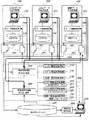
本発明の一実施形態による複数設計支援システム対応データ統合装置の構成を図1に示す。図の例では、複数設計支援システム対応データ統合装置がCADシステム1100、CADシステム1200、帳票システム1300といった複数の設計支援システムの設計データを対象に動作するものとしている。複数設計支援システム対応データ統合装置は、設計データ・スプール2000、データ変換・逆変換装置3000、統合データベース4000、情報検索表示装置5000および監視・制御装置6000を備えている。またそのデータ変換・逆変換装置3000は、構造変換情報呼び出し装置3100、構造逆変換情報呼び出し装置3200を備えるとともに、これら構造変換情報呼び出し装置3100と構造逆変換情報呼び出し装置3200のそれぞれについて、データ統合対象の各設計支援システムに対応する構造変換情報格納手段(構造変換情報呼び出し装置3100用は構造変換情報格納手段であり、構造逆変換情報呼び出し装置3200用は構造逆変換情報格納手段となる)を備えている。
【0011】
図の例では、構造変換情報格納手段として、CADシステム1100に対応するCAD1構造変換情報格納手段3110、CADシステム1200に対応するCAD2構造変換情報格納手段3120、帳票システム1300に対応する帳票1構造変換情報格納手段3130を備えている。また構造逆変換情報格納手段として、CADシステム1100に対応するCAD1構造逆変換情報格納手段3210、CADシステム1200に対応するCAD2構造逆変換情報格納手段3220、帳票システム1300に対応する帳票1構造逆変換情報格納手段3230を備え、それぞれにはCAD1フォーマット格納手段3211、CAD2フォーマット格納手段3221、帳票1フォーマット格納手段3231が付随している。
【0012】
ここで、統合データベース4000には、CADシステム1100、CADシステム1200、帳票システム1300などの複数の設計支援システムに固有な構造の設計データを統一的なものにする基となる統一的な製品構成情報が格納されている。つまり統合データベース4000は、統一的製品構成情報の格納手段としての機能も負っている。
【0013】
各設計支援システムから変換対象として出力されるデータは、設計データ・スプール2000に一旦蓄積されてからデータ変換・逆変換装置3000で変換を受ける。より具体的には、各設計支援システムから順方向の変換対象として出力される設計データは、各設計支援システム1100、1200、1300それぞれのデータ編集装置1120、1220、1320よりそれぞれに固有のフォーマットで出力され、CAD1データ1121、CAD2データ1221、帳票1データ1321として設計データ・スプール2000に一旦格納され、そこからデータ変換・逆変換装置3000に取り込まれて変換処理を受ける。そして、統合データベース4000に格納されている統一的な製品構成情報に対応付けて統合形式に変換された後のデータは統合データベース4000に格納される。
【0014】
一方、データ変換・逆変換装置3000で生成される逆変換後のデータは、設計データ・スプール2000に一旦蓄積されてから対応する設計支援システムに取り込まれる。より具体的には、データ変換・逆変換装置3000において統合データベース4000に格納の統合形式によるデータを逆変換して各設計支援システムで扱えるように適合させた設計データは、CAD1データ3101、CAD2データ3201、帳票1データ3301として設計データ・スプール2000に一旦格納され、そこから各設計支援システム1100、1200、1300にそれぞれのデータ編集装置1120、1220、1320を介して取り込まれる。したがって、他のCADで作成した情報も、統合データベース4000を介してデータを取り込むことで、自CADデータの不足分を補う情報として利用することができることになる。
【0015】
統合データベース4000に格納されている統合構造による設計データなどは、情報検索表示装置5000を介して、データ変換・逆変換の監視・制御装置6000の表示画面に表示することにより可視化できるようにされている。つまり本実施形態では情報検索表示装置5000が統合データベース4000のデータを可視化するための手段の主要部を構成している。ただこれについては、情報検索表示装置5000の機能を監視・制御装置6000に負わせるようにすることも可能である。また、監視・制御装置6000は、設計データ・スプール2000、データ変換・逆変換装置3000の監視・制御、統合データベース4000における製品構成情報の追加・編集処理などにも使用できる。なお、CADシステム1100は、CADデータ入出力装置1110、データ編集装置1120、CAD固有のデータベース1130からなり、CADシステム1200も同様に、CADデータ入出力装置1210、データ編集装置1220、CAD固有のデータベース1230からなる。一方、帳票システム1300は、帳票データ入出力装置1310、データ編集装置1320、帳票データベース1330からなる。
【0016】
データ変換・逆変換装置3000の構造変換情報呼び出し装置3100と構造逆変換情報呼び出し装置3200はそれぞれ、CADデータ入出力装置1110、1210、帳票データ入出力装置1310および監視・制御装置6000のいずれからも制御できるようにされている。構造変換情報呼び出し装置3100は、変換対象の設計データの設計データ・スプール2000への蓄積が完了した後に、CADデータ入出力装置1110、1210、帳票データ入出力装置1310のいずれかから指示を受けることで起動する。起動後、変換対象のデータの種類に対応して、CAD1構造変換情報格納手段3110、CAD2構造変換情報格納手段3120、帳票1構造変換情報格納手段3130のそれぞれに格納されている後述のような構造変換情報の中から該当する情報を選択し、その選択した構造変換情報に基づいてトランスレータプログラムにより、CADシステム1100、CADシステム1200、帳票システム1300のいずれかからの設計データを統合データベースに入力できる形に変換する。また、構造逆変換情報呼び出し装置3200も、同じく、CADデータ入出力装置1110、1210、帳票データ入出力装置1310のいずれかの指示で起動する。構造逆変換情報呼び出し装置3200は起動後、逆変換対象のデータの種類と範囲に対応して、CAD1構造逆変換情報格納手段3210、CAD2構造逆変換情報格納手段3220、帳票1構造逆変換情報格納手段3230のそれぞれに格納されている後述のような構造逆変換情報の中から該当する情報を選択し、その選択した構造逆変換情報に基づいて逆トランスレータプログラムにより統合データベース中のデータをCADシステム1100、CADシステム1200、帳票システム1300のいずれかに適合する設計データに逆変換し、設計データ・スプール2000に蓄積する。
【0017】
図2は統合データベース4000に格納されており、そこで用いられる統一的な製品構成情報の一例を示している。まず、図2(a)に設計データ4100−aの構成を示す。全ての設計データはこの構成によって統合データベース4000に格納される。格納後の設計データの具体例を図10に示す。設計データ4100−aは、設計データの一個一個を識別するためのID 4100−bと、部品種別4100−c、部品属性4100−d、部品構成4100−e、接続情報4100−g、座標4100−g、形状4100−h、入力元情報4100−iからなる。このうちID 4100−bと部品種別4100−cは必須であるが、その他の4100−dから4100−iは必要に応じて使用する。
【0018】
図2(b)は部品種別として利用するクラス情報の一例である。クラス情報とは設計データの種別を分類するための情報である。このクラス情報は合成関係と継承関係からクラス間の関係が表される。合成関係は全体−部分の構成関係を表し、接続線の◇シンボル側が全体、◇シンボルと反対側が部分のクラスを表す。また、継承関係は親−子の分類関係を表し、接続線の△シンボル側が親分類、△シンボルと反対側が子分類のクラスを表す。したがって、図2(b)では、プラント4200−aは系統4200−bが複数集まって構成され、個々の系統4200−bはライン4200−cが複数集まって構成され、個々のライン4200−cはサブライン4200−dが複数集まって構成され、個々のサブライン4200−dはプラント構成要素4200−eが複数集まって構成される。また、系統4200−bは、配管系統4200−b−1、機器系統4200−b−2、電気系統4200−b−3に分類される。
【0019】
図2(c)はプラントの主要な部品を構成するプラント構成要素4200−eにおける親子関係の分類について一例を示したものである。プラント構成要素4200−eは、属性として名称4200−e−1を有するとともに、配管部品4300−bと計装部品4300−cに分類される。配管部品4300−bは、属性として呼び径4300−b−1を有し、配管4300−dと弁4300−eとフィッティング4300−fに分類される。配管4300−dは直管4300−gに分類される。直管4300−gは、属性として長さ4300−g−3を有するとともに、上位階層のクラスから継承した名称4300−g−1(プラント構成要素で定義、ここから継承した属性)と呼び径4300−g−2(配管部品で定義、ここから継承した属性)を利用することができる。
【0020】
図2(d)はプラント構成要素4200−eの図形表現に係わるクラス間の関係の一例を表したものである。プラント構成要素4200−eはプラント構成要素形状4400−bが複数集まって構成され、個々のプラント構成要素形状4400−bは形状表現要素4400−cが複数集まって構成され、個々の形状表現要素4400−cは幾何表現要素4400−dが複数集まって構成される。プラント構成要素形状4400−bは2次元図形か3次元図形に分類され、さらに3次元図形は詳細図形か概要図形に分類される。また、幾何表現要素4400−dは直線部品組合せか多角形部品組合せか立体部品組合せに分類される。さらに、立体部品組合せは、立方体か円柱か四角錐に分類される。以上の図2(b)、(c)、(d)のクラス情報から必要なものを選択して、図2(a)の設計データとして利用することになる。
【0021】
図3に、CADシステム1100の出力データの構成と具体的なデータの例を示す。CAD1データ1121は、図3(a)に示すようにCADシステム1100の定める固有のフォーマットでCADデータを出力したものである。CAD1データ1121は図3(b)に定めるクラス構造に従う。すなわち、全体構造1130aは部屋1130bが複数集まって構成され、個々の部屋1130bは配管系統1130cが複数集まって構成され、個々の配管系統1130cは要素1130dが複数集まって構成される。また、個々の要素1130dは属性としてID、形状、開始座標、終了座標、最高使用圧力、最高使用温度、材質を有する。図3(b)のような構造で情報を表現した場合の具体的に格納されるデータの構造(インスタンス構造と呼ぶ)を表したのが図3(c)である。CAD1データ1130a−1は部屋A 1130b−1と部屋B 1130b−2からなる。また、部屋A 1130b−1は配管系統A 1130c−1と配管系統B1130c−2からなる。さらに配管系統A 1130c−1は配管a 1130d−1、配管b 1130d−2、弁a 1130d−3、エルボa 1130d−4からなる。このように見ると図3(b)のクラス構造はデータが入るための情報の抽象的な表現形式、図3(c)のインスタンス構造は具体的なデータが入ったあとの情報の表現構造ということができる。このようなCADシステム固有の情報表現形式は、図2に示した標準的な製品構成情報と対比すれば明らかなように、それとは大きく異なっており、またそうであるのが一般的である。
【0022】
図4に、CADシステム1200の出力データの構成と具体的なデータの例を示す。CAD2データ1221は、図4(b)に示すようにCADシステム1200の定める固有のフォーマットでCADデータを出力したものである。CAD2データ1221は図4(b)に定めるクラス構造に従う。すなわち、全体構造1230aは部屋1230bが複数集まって構成され、個々の部屋1230bは構造系1230cが複数集まって構成され、個々の構造系1230cは構造部材1230dが複数集まって構成され、個々の構造部材1230dは構造要素1230eが複数集まって構成される。また、個々の構造要素1230eは属性としてID、形状、断面形状、開始座標、終了座標を有する。図4(b)のようなクラス構造で情報を表現した場合のインスタンス構造を表したのが図3(c)である。CAD2データ1230a−1は部屋A 1230b−1と部屋B 1230b−2からなる。また、部屋A 1230b−1は構造系A 1230c−1と構造系B 1230c−2からなる。さらに構造系A 1230c−1は構造部材A 1230d−1、構造部材B 1230d−2からなる。そして構造部材1230d−1はID S0001 1230e−1とID S0002 1230e−2からなる。このように図4(b)のクラス構造もまた、データが入るための情報の抽象的な表現形式、図4(c)のインスタンス構造は具体的なデータが入ったあとの情報の表現構造ということができる。このCADシステム固有の情報表現形式も図2に示したような標準的な製品構成情報とは大きく異なる。
【0023】
図5に、帳票システム1300の出力データの構成と具体的なデータの例を示す。帳票1データ1321は、例えば図5(a)のように表形式でデータが表現される。列名として系統番号、弁番号、弁名称、形式、操作、弁箱材種などが表現される。これらの情報をもとに、クラス構造は図5(b)のように表現される。すなわち、弁テーブルというクラス1330−aが一つあり、系統番号、弁番号、弁名称、形式、操作、弁箱材種などが属性として表現される。弁テーブルの行をユニークな情報として識別する主キーとして、系統番号、弁番号を利用することにより、具体的な弁という情報を構成する情報として弁情報の行データが存在するインスタンス構造が構成される。これらの情報も通常は、図2に示したような標準的な製品構成情報とは大きく異なる。
【0024】
図6に、CAD1データ構造から統合データベース構造への対応付けに係わる、つまり固有の製品構成とデータ表現形式を有するCAD1データを統一的製品構成情報と表現形式による統合データベース4000に格納のデータへ変換するのに用いられる構造変換情報の例を示す。構造変換情報3110fは、CAD1データのクラス構造と該クラス構造で使われる具体的な値(円柱など)の情報を用いて、標準的な製品構成情報で用意されているクラス構造との間の対応関係を、直線による接続で表したものと該直線上で作用する関数、条件判断からなる。CAD1データの配管系統クラスと要素クラスの形状から、製品構成情報中で準備されている配管のうちの直管クラスを利用する。そして、要素の属性のうちのIDの値を利用して、直管に係わるIDとしてIDp1を生成する関数を作用させる。直管の中で利用可能な属性のうち、要素で利用されている最高使用圧力、最高使用温度、材質をCAD1データと製品構成情報の間で対応付ける。また、CAD1データの図形情報を統合データベースに保存するために、プラント構成要素形状クラス、形状表現要素クラス、円柱クラスを製品構成情報側に用意する。これらのクラスに関してもCAD1データの要素IDごとに具体的な情報(インスタンス情報と呼ぶ)を生成するために要素IDと対応付けて、それぞれIDps1、IDsr1、IDgr1といったIDについてID生成関数を作用させることにより生成する。また、プラント構成要素形状の部品種別を3次元図形の中の概要図形であると規定し、円柱の中で利用可能な属性のうち、半径、長さ、座標について変換関数を通して要素の開始座標、終了座標、口径から計算できるようにする。以上の構造変換情報3110fを利用することでCAD1データから統合データベースで利用する製品構造情報に対応づく情報を生成できる。なお、CAD1データとは異なる構造を有するCAD2データ、帳票1データに関しても統合データベースの製品構成情報に対応付けた変換をなせるようにしてあるが、それに用いる構造変換情報はCAD1データの場合と基本的に同様であるので、その説明は省略する。
【0025】
図7に、統合データベース構造からCAD1データ構造への対応付けに係わる、つまり統一的製品構成情報と表現形式による統合データベース4000に格納のデータを固有の製品構成とデータ表現形式のCAD1データへ変換するのに用いられる構造逆変換情報の例を示す。CAD1データ構造と統合データ構造で利用する製品構造情報は図6と同一である。ここでは逆構造変換情報3210r1とCAD1データのフォーマット(インデント、データ区切り、データの並びなど)3210r2を予め用意することで、統合データベースの製品構造情報で指定した範囲のクラスに関して、元のCAD1データの形式にデータを逆変換することができるようにしている。またここでは、IDp1に関連するIDであるIDps1、IDsr1、IDgr1を元にIDを生成するID逆変換関数を利用することでCAD1データの要素に係わるインスタンスを復元する。また、それぞれ統合データベースで利用する製品構成情報のクラスからCAD1データのクラス、属性に対し直線による接続で逆方向に表したものと該直線上で作用する関数、条件判断から逆構造変換情報3210r1を構成する。このような情報を用意することで統合データベースに格納されているインスタンスのデータからCAD1データの構造にしたがったデータを逆変換して復元することができる。CAD2データ、帳票1データに関しても、CAD1データについての例と基本的に同様な逆構造変換情報とそれぞれのデータフォーマットを用意することで、それぞれのデータ構造に従ったデータを復元することができるようにしてあるが、それについての説明は省略する。
【0026】
以上のような構造変換情報と構造逆変換情報はトランスレータプログラムに埋め込まれることなく外部化されている。すなわち構造変換情報は、上述のように、それぞれに対応する図1の構造変換情報格納手段3110、3120、3130に格納されており、必要に応じて構造変化情報呼び出し装置3100により呼び出して利用されるようになっている。また、構造逆変換情報も、上述のように、それぞれに対応する図1の構造逆変換情報格納手段3210、3220、3230に格納されており、必要に応じて構造逆変換情報呼び出し装置3200により呼び出して利用されるようになっている。このように各設計支援システムに固有の形式によるデータと統合データベースに格納の統合的な形式によるデータの間の対応付けに関する構造変換情報を明確に外部化しておくことにより、構造変換情報を可視化することができ、そのことによって構造変換情報の再利用が容易となり、異なる設計支援システム間で設計結果を意味ある構造で有機的に結合して統合することがやり易くなる。また設計支援システム側の少変更、製品構成情報の少変更にも、対応関係の構造を少変更することで容易に対応することができる。
【0027】
図8に、CAD1データを統合データベースに格納する際の処理の流れを示す。この処理は構造変換情報呼び出し装置3100の動作を表したものである。本処理では、CADデータ入出力装置1110からデータ変換・逆変換装置3000へのCAD1データ変換処理指示が出された後に、構造変換情報呼び出し装置3100が起動する。まず、設計データ・スプール2000に一旦蓄積されているCAD1データを読み出す(STEP F10)。次に、図6で示したような構造変換情報を構造変換情報呼び出し装置3100において、CAD1構造変化情報格納手段3110から呼び出し(読み込む)、これを基にトランスレータプログラムが変換を実行する(STEP F20)。そして、変換後の情報を統合データベースに向けて出力し(STEP F30)、続いて統合データベースに変換後の情報を格納する(STEP F40)。変換後の情報は図2(a)の形式で、具体的例としては図10に示すようなもので表現される。変換後の情報に関しては、変換前の設計支援システムの名称を付加して格納することとし、すでに統合データベース内に設計データが格納されていて、変換後のデータ(値)が異なる場合も、そのデータとデータを作成した設計支援システムの名称をそのまま重複して格納する。この場合、設計データを逆変換により取り出す場合には、設計データに矛盾があるということと、どのデータを逆変換用に利用するかユーザに問い合わせるようにする。CAD1データ以外の設計データに関しても、それぞれに対応する構造変換情報を用いて上で説明したのと同様な処理を行うことにより、統合データベースに格納可能な形に設計データ変換することができる。
【0028】
図9に、統合データベースに格納のデータをCAD1データに逆変換する際の処理の流れを示す。本処理でも図8の処理と同様にCADデータ入出力装置1110からデータ変換・逆変換装置3000へのCAD1データ逆変換処理指示が出された後に、構造逆変換情報呼び出し装置3200が起動する。まず、CADデータ入出力装置1110を用いて、データ逆変換範囲を指定する(STEP R10)。次に、構造逆変換情報呼び出し装置3200において、CAD1構造逆変換情報格納手段3210からCADシステム1100用のCAD1構造逆変換情報を呼び出す(読み込む)とともにCAD1構造逆変換情報格納手段3210に付随するCAD1フォーマット格納手段3211からCADシステム1100用のCAD1フォーマットを呼び出す(読み込む)(STEP R20)。次いで、変換範囲のクラスに対応するインスタンス情報を統合データベース4000より読み込む(STEP R30)。それから、読み込んだインスタンスに対応するCADデータをCAD1構造逆変換情報に基づいて逆トランスレータプログラムによりCAD1フォーマットで生成する(STEP R40)。生成したCAD1データ3101は設計データ・スプール2000に出力する(STEPR50)。そして最後に、CADデータ入出力装置1110を介して、逆変換されたCADデータについて、データ編集装置1120を通して読み込み、CAD1固有のデータベース1130に蓄積される(STEP R60)。構造逆変換情報呼び出し装置3200を用いた設計データの逆変換処理は、統合データベースを介することにより、CAD1データへの逆変換以外についても行うことができる。すなわち、他の設計支援システムで作成されたデータの読み込みや作成した設計データの復元を自在になすことができる。
【0029】
以上の順方向変換や逆方向変換では、構造変換情報に基づいてのトランスレータプログラムによる変換処理をなすものとなっているが、ここで用いられるトランスレータプログラムは構造変換情報が与えられていることにより、この分野の技術者であれば容易に作成できるものである。したがってトランスレータプログラムについての具体的な説明は省略する。
【0030】
図10に、CAD1からの変換後のデータの一例を示す。この例では、World Wide Web Consortium(W3C)で規定・標準化されているExtensible Markup Language(XML)を用いて統合データベースに格納するための変換後のデータを記述してある。データ構造は図2(a)の設計データの構造にしたがっている。すなわち、属性としてIDを持つ設計データタグがあり、その中に部品種別や形状、部品構成、属性などのタグがある。そして、設計データがそれぞれインスタンスとしてIDを持ちながら表現され、形状や部品構成情報タグを介して関連づいている。
【0031】
図11に、統合データベース4000に格納されているデータを可視化する情報検索画面の一例を示す。統合データベース4000から情報検索表示装置5000を介して、監視・制御装置6000からの操作で図形や属性を可視化する。ここでは、例えば、設計情報検索結果の表示ウィンドウ6000−aで配管クラスのインスタンスPA001を指定することにより、この配管に関わるインスタンスを統合データベースから検索・収集することにより3次元形状と属性名称、単位付きの属性値を表示することができる。したがって、本発明におけるこのような実施形態によれば、統合化後のデータの全体を特別なCADなどの設計支援装置を導入しなくても可視化できる。すなわち、複数設計支援システム対応データ統合装置に接続しているCADシステム1100、1200や帳票システム1300は、逆変換を通じて統合データベース4000に格納の統合形式データの全体を見ることができるが、このように複数設計支援システム対応データ統合装置に接続する設計支援システムを有しないユーザの場合にはそれができない。このようなユーザが何らかの理由で複数設計支援システム対応データ統合装置での統合データの全体を見たいという場合に、特別なCADなどの設計支援システムを導入しなくとも、それが可能になるということである。
【0032】
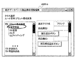
図12に、統合データベースに格納の製品構成情報を編集する、つまり製品構成情報に情報を追加する操作を行う際に用いる構造編集画面の一例を示す。図6や図7のような、構造変換情報や逆構造変換情報を生成する際に、統合データベースで利用する製品構成情報に関して、不足するクラスや属性が発生した場合に、本機能を利用する。すなわち、統合データベース製品構成情報編集ウィンドウ6000−bを利用することによって、配管部品の分類クラスとして、フランジというものがなかったときに、配管部品クラスを選択して、追加クラス名としてフランジを入力することにより、不足しているクラスを追加する。また、属性や部品構成に関しても、同様に追加することが可能である。
【0033】
図13に、データ変換・逆変換状況の監視画面の一例を示す。ここでは、データ変換・逆変換モニタ6000−cを利用することで、変換対象CAD、変換範囲、変換・逆変換の種別、進行状況を知ることができる。また、監視・制御装置6000からの直接の指示でデータ変換・逆変換装置3000に作用して、変換・逆変換処理を中断することができる。処理を中断した場合には、関係する設計支援システムに処理中断の情報を伝達する。
【0034】
【発明の効果】
以上説明したように本発明では、各設計支援システムに固有な構造のデータとこれらを統合する構造のデータとの間でのデータ変換・逆変換について用いられる構造変換に関する情報である構造変換情報を独立のデータとして格納手段に格納することで外部化するようにしている。したがって本発明によれば、構造変換情報の再利用が容易となるし、また修正なども軽微であれば簡単に対応することができ、異なる設計支援システム間における設計結果の意味ある構造での有機的な統合をより容易に行うことが可能となり、設計支援システムによる設計業務の効率改善に大きく寄与できる。また本発明では、統合データベースに格納してある統合形式のデータを可視化できるようにしている。したがって本発明によれば、統合データの可視化について、特別なCADなどの設計支援装置の導入を不要にすることができる。また本発明では、製品構成情報の編集を行うための構造編集画面を表示できるようにしている。したがって本発明によれば、製品構成情報に不足分があってもそれを追加する操作を容易に行うことができ、データ統合の有用性をさらに高めることができる。
【図面の簡単な説明】
【図1】一実施形態による複数設計支援システム対応データ統合装置の構成を複数の設計支援システムと関係させて示す図である。
【図2】統合データベースで利用する製品構成情報の一例を示す図である。
【図3】あるCADシステムの出力データの構成と具体的なデータの例を示す図である。
【図4】他のCADシステムの出力データの構成と具体的なデータの例を示す図である。
【図5】帳票システムの出力データの構成と具体的なデータの例を示す図である。
【図6】あるCADに固有のCADデータ構造情報を統合構造のデータへ変換するのに用いられる構造変換情報の例を示す図である。
【図7】統合構造のデータをあるCADに固有のデータ構造へ変換するのに用いられる構造逆変換情報の例を示す図である。
【図8】CADからのデータを統合データベースに格納する際の処理の流れを示す図である。
【図9】統合データベースに格納のデータを逆変換してCADに取り込む処理の流れを示す図である。
【図10】統合形式に変換後のデータの一例を示す図である。
【図11】情報検索画面の一例を示す図である。
【図12】統合データベースの構造編集画面の一例を示す図である。
【図13】データ変換・逆変換状況の監視画面の一例を示す図である。
【符号の説明】
1100 CADシステム(設計支援システム)
1200 CADシステム(設計支援システム)
1300 帳票システム1(設計支援システム)
2000 設計データ・スプール
3000 データ変換・逆変換装置
3110 構造変換情報格納手段
3120 構造変換情報格納手段
3130 構造変換情報格納手段
3210 構造逆変換情報格納手段
3220 構造逆変換情報格納手段
3230 構造逆変換情報格納手段
4000 統合データベース
5000 情報検索表示装置
6000 監視・制御装置[0001]
TECHNICAL FIELD OF THE INVENTION
In the present invention, for example, as in an example in a field related to a plant life cycle such as plant design, operation, and maintenance, design work is divided into divisions of work. The present invention relates to a data integration device for supporting more efficient transmission and sharing of information performed by a database in a design support system, that is, a data integration device compatible with a plurality of design support systems.
[0002]
[Prior art]
For example, in the power plant manufacturing industry such as nuclear power and thermal power plants, using the easy-to-use data processing tools (design support system) throughout the plant life cycle such as the design stage, operation / maintenance stage, and disposal stage, the design results and maintenance results are obtained. And so on. However, the structure of the database used by each of them and the items handled in the database usually differ greatly, and the data at the design stage was not often reused at the operation and maintenance stage. Even in the design stage, design is performed using different CAD tools for system design, piping design, structural design, equipment design, etc., so the design results in each design stage have a meaningful structure even in the design stage. It was quite difficult to combine and integrate organically. In order to solve this problem, a standard model of a product structure related to design data called STEP (standard for the product of model data) is created internationally by ISO or the like, and data from a plurality of design support systems are integrated or different. Data is being exchanged between design support systems. In addition, an attempt has been made to integrate design data of a heterogeneous design support system by constructing a translator using a PDM (product data management) system (for example, Non-Patent Document 1).
[0003]
[Non-patent document 1]
Magazine "Computer-Aided Design" vol. 33 (2001) pp521-529, "Mapping product structures between CAD and PDM systems using UML".
[0004]
[Problems to be solved by the invention]
Regarding the use of the above-mentioned standard model of the product structure by the ISO and the like standard model, a program called a translator for associating the structure of the design data in each of the different design support systems with the standard model is constructed, and the It is necessary to implement data integration between support systems. Then, a translator program is created for each of the forward conversion from the design data of each design support system to the standard model and the reverse conversion from the standard model to the design data of each design support system. As described above, in the method of performing the structure conversion between the design data of each design support system and the standard model by the translator program, the information of the structure conversion is conventionally embedded in the program language, and the structure conversion information is black box-like. Has become. For this reason, for example, when a group B is newly added to the integration of data performed in the group A and a translator program for the group B is created, the structural conversion information used in the group A is also used in the group B. There is a problem that it is difficult to reuse the structure conversion information when it is said to be used.
[0005]
Also, there has been no mechanism for centrally managing an integrated database for managing data associated with a translator program and a standard model. For this reason, 1) the data integration status must be confirmed unless all data stored in the integrated database is converted to a format compatible with one of a plurality of CADs (design support systems) to be integrated. No, 2) there is a problem that the program needs to be recreated each time the standard model to be associated with the CAD data has a missing item.
[0006]
SUMMARY OF THE INVENTION The present invention has been made in view of such conventional circumstances, and has as its object to provide a data integration device for a multiple design support system that facilitates reuse of structure conversion information and the like. It is an object of the present invention to provide a data integration device that can easily confirm the data and can easily add missing items in a standard model for data integration when there are missing items.
[0007]
[Means for Solving the Problems]
In order to achieve the above object, the present invention provides a data integration device for a plurality of design support systems that supports integration of data between a plurality of design support systems each having data having a different structure. , Structure conversion information storage means, wherein the product structure information storage means stores one unified product configuration information, and the structure conversion information storage means stores data of a structure unique to each of the design support systems. Is used to convert data of the integrated structure into data of a structure specific to each of the design support systems, and structure conversion information for converting the integrated product configuration information into data of an integrated structure based on the unified product configuration information. The structure conversion information is stored.
[0008]
Further, in the present invention, the data integration device for a plurality of design support systems as described above includes an integrated database for storing integrated data converted based on the structure conversion information, and visualizes data stored in the integrated database. Means.
[0009]
Further, in the present invention, a structure editing screen for editing the product configuration information can be displayed for the data integration device compatible with the multiple design support system as described above.
[0010]
BEST MODE FOR CARRYING OUT THE INVENTION
FIG. 1 shows a configuration of a data integration device for a multiple design support system according to an embodiment of the present invention. In the example shown in the figure, the data integration device corresponding to a plurality of design support systems operates on design data of a plurality of design support systems such as a
[0011]
In the example of the figure, as the structure conversion information storage means, CAD1 structure conversion information storage means 3110 corresponding to
[0012]
Here, the integrated
[0013]
Data output from each design support system as a conversion target is once stored in a
[0014]
On the other hand, the data after the inverse conversion generated by the data conversion /
[0015]
The design data and the like based on the integrated structure stored in the
[0016]
The structure conversion
[0017]
FIG. 2 shows an example of unified product configuration information stored in the
[0018]
FIG. 2B is an example of class information used as a component type. The class information is information for classifying the type of design data. This class information indicates the relationship between the classes from the composition relationship and the inheritance relationship. The composition relationship represents the whole-part configuration relationship, in which the {symbol side of the connection line represents the whole, and the side opposite to the {symbol} represents the class of the part. In addition, the inheritance relationship indicates a parent-child classification relationship, in which the △ symbol side of the connection line represents the parent classification, and the opposite side of the △ symbol represents the child classification class. Therefore, in FIG. 2B, the plant 4200-a is configured by a plurality of systems 4200-b, each system 4200-b is configured by a plurality of lines 4200-c, and each line 4200-c is A plurality of sub-lines 4200-d are configured, and each sub-line 4200-d is configured by a plurality of plant components 4200-e. The system 4200-b is classified into a piping system 4200-b-1, an equipment system 4200-b-2, and an electric system 4200-b-3.
[0019]
FIG. 2C shows an example of the classification of the parent-child relationship in the plant component 4200-e that constitutes the main part of the plant. The plant component 4200-e has a name 4200-e-1 as an attribute and is classified into a piping component 4300-b and an instrumentation component 4300-c. The pipe part 4300-b has a nominal diameter 4300-b-1 as an attribute, and is classified into a pipe 4300-d, a valve 4300-e, and a fitting 4300-f. The pipe 4300-d is classified as a straight pipe 4300-g. The straight pipe 4300-g has a length 4300-g-3 as an attribute, a name 4300-g-1 (defined by a plant component, an attribute inherited from this) and a
[0020]
FIG. 2D illustrates an example of a relationship between classes related to the graphic expression of the plant component 4200-e. The plant component 4200-e is configured by a plurality of plant component shapes 4400-b, and the individual plant component shape 4400-b is configured by a plurality of shape expression components 4400-c. −c is configured by gathering a plurality of geometric expression elements 4400-d. The plant component shape 4400-b is classified into a two-dimensional figure or a three-dimensional figure, and the three-dimensional figure is further classified into a detailed figure or a general figure. Further, the geometric expression element 4400-d is classified into a combination of a straight part, a combination of polygons, and a combination of three-dimensional parts. Further, the three-dimensional component combination is classified into a cube, a cylinder, and a quadrangular pyramid. Necessary items are selected from the class information shown in FIGS. 2B, 2C, and 2D and used as design data in FIG. 2A.
[0021]
FIG. 3 shows a configuration of output data of the
[0022]
FIG. 4 shows a configuration of output data of the
[0023]
FIG. 5 shows a configuration of output data of the
[0024]
FIG. 6 relates to the mapping from the CAD1 data structure to the integrated database structure, that is, converts CAD1 data having a unique product configuration and data representation format into data stored in the
[0025]
FIG. 7 relates to the association from the integrated database structure to the CAD1 data structure, that is, converts the data stored in the
[0026]
The structure conversion information and the structure reverse conversion information described above are externalized without being embedded in the translator program. That is, as described above, the structure conversion information is stored in the corresponding structure conversion
[0027]
FIG. 8 shows a flow of processing when CAD1 data is stored in the integrated database. This processing represents the operation of the structure conversion
[0028]
FIG. 9 shows a flow of processing when data stored in the integrated database is inversely converted into CAD1 data. In this process, similarly to the process in FIG. 8, after the CAD data input /
[0029]
In the above forward conversion and backward conversion, the translator program performs the conversion process based on the structure conversion information, but the translator program used here is given the structure conversion information, Engineers in this field can easily create the file. Therefore, a specific description of the translator program is omitted.
[0030]
FIG. 10 shows an example of data after conversion from CAD1. In this example, the converted data to be stored in the integrated database is described using Extensible Markup Language (XML) defined and standardized by the World Wide Web Consortium (W3C). The data structure follows the structure of the design data in FIG. That is, there is a design data tag having an ID as an attribute, and among them, tags such as a component type, a shape, a component configuration, and an attribute are included. Then, the design data is expressed while each having an ID as an instance, and is related via a shape or a component configuration information tag.
[0031]
FIG. 11 shows an example of an information search screen for visualizing data stored in the
[0032]
FIG. 12 shows an example of a structure editing screen used when editing the product configuration information stored in the integrated database, that is, when performing an operation of adding information to the product configuration information. When generating the structure conversion information and the inverse structure conversion information as shown in FIGS. 6 and 7, this function is used when a missing class or attribute occurs in the product configuration information used in the integrated database. In other words, by using the integrated database product configuration information editing window 6000-b, when there is no flange as a piping component classification class, a piping component class is selected and a flange is input as an additional class name. By adding missing classes. Also, attributes and component configurations can be similarly added.
[0033]
FIG. 13 shows an example of a data conversion / reverse conversion status monitoring screen. Here, by using the data conversion / inverse conversion monitor 6000-c, the CAD to be converted, the conversion range, the type of conversion / inverse conversion, and the progress can be known. Further, the data conversion /
[0034]
【The invention's effect】
As described above, in the present invention, the structure conversion information, which is the information on the structure conversion used for the data conversion / inverse conversion between the data of the structure unique to each design support system and the data of the structure integrating these, is described. It is externalized by storing it as independent data in storage means. Therefore, according to the present invention, it is easy to reuse the structure conversion information, and it is possible to easily cope with the modification if the modification is minor. Integration can be performed more easily, which can greatly contribute to the improvement of the efficiency of the design work by the design support system. Further, according to the present invention, data in an integrated format stored in an integrated database can be visualized. Therefore, according to the present invention, it is not necessary to introduce a special design support device such as CAD for visualizing integrated data. In the present invention, a structure editing screen for editing product configuration information can be displayed. Therefore, according to the present invention, even if there is a shortage in the product configuration information, an operation of adding the shortage can be easily performed, and the usefulness of data integration can be further enhanced.
[Brief description of the drawings]
FIG. 1 is a diagram showing a configuration of a data integration device corresponding to a plurality of design support systems according to an embodiment in relation to a plurality of design support systems.
FIG. 2 is a diagram illustrating an example of product configuration information used in an integrated database.
FIG. 3 is a diagram showing a configuration of output data of a certain CAD system and an example of specific data.
FIG. 4 is a diagram showing a configuration of output data of another CAD system and an example of specific data.
FIG. 5 is a diagram showing a configuration of output data of a form system and an example of specific data.
FIG. 6 is a diagram showing an example of structure conversion information used to convert CAD data structure information unique to a certain CAD into data of an integrated structure.
FIG. 7 is a diagram showing an example of structure reverse conversion information used to convert data of an integrated structure into a data structure unique to a certain CAD.
FIG. 8 is a diagram showing a flow of processing when data from a CAD is stored in an integrated database.
FIG. 9 is a diagram showing a flow of a process of inversely converting data stored in an integrated database and taking in the CAD.
FIG. 10 is a diagram illustrating an example of data converted to an integrated format.
FIG. 11 is a diagram showing an example of an information search screen.
FIG. 12 is a diagram showing an example of a structure editing screen of the integrated database.
FIG. 13 is a diagram showing an example of a data conversion / inverse conversion status monitoring screen.
[Explanation of symbols]
1100 CAD system (design support system)
1200 CAD system (design support system)
1300 Form System 1 (Design Support System)
2000 Design Data Spool
3000 data conversion / inversion device
3110 Structure conversion information storage means
3120 Structure conversion information storage means
3130 Structure conversion information storage means
3210 Structural inverse conversion information storage means
3220 Structural inverse conversion information storage means
3230 Structural inverse conversion information storage means
4000 Integrated Database
5000 Information retrieval and display device
6000 monitoring and control equipment
Claims (3)
Priority Applications (1)
| Application Number | Priority Date | Filing Date | Title |
|---|---|---|---|
| JP2002356233A JP2004192091A (en) | 2002-12-09 | 2002-12-09 | Data integration device for multiple design support systems |
Applications Claiming Priority (1)
| Application Number | Priority Date | Filing Date | Title |
|---|---|---|---|
| JP2002356233A JP2004192091A (en) | 2002-12-09 | 2002-12-09 | Data integration device for multiple design support systems |
Publications (1)
| Publication Number | Publication Date |
|---|---|
| JP2004192091A true JP2004192091A (en) | 2004-07-08 |
Family
ID=32756623
Family Applications (1)
| Application Number | Title | Priority Date | Filing Date |
|---|---|---|---|
| JP2002356233A Pending JP2004192091A (en) | 2002-12-09 | 2002-12-09 | Data integration device for multiple design support systems |
Country Status (1)
| Country | Link |
|---|---|
| JP (1) | JP2004192091A (en) |
Cited By (3)
| Publication number | Priority date | Publication date | Assignee | Title |
|---|---|---|---|---|
| US7859544B2 (en) | 2006-08-11 | 2010-12-28 | Kabushiki Kaisha Toshiba | Data federation system, and control method and control program thereof |
| JP2020102115A (en) * | 2018-12-25 | 2020-07-02 | 横河電機株式会社 | Engineering support system and engineering support method |
| JP2021124785A (en) * | 2020-01-31 | 2021-08-30 | 富士フイルムビジネスイノベーション株式会社 | Management equipment, management programs, and management systems |
-
2002
- 2002-12-09 JP JP2002356233A patent/JP2004192091A/en active Pending
Cited By (4)
| Publication number | Priority date | Publication date | Assignee | Title |
|---|---|---|---|---|
| US7859544B2 (en) | 2006-08-11 | 2010-12-28 | Kabushiki Kaisha Toshiba | Data federation system, and control method and control program thereof |
| JP2020102115A (en) * | 2018-12-25 | 2020-07-02 | 横河電機株式会社 | Engineering support system and engineering support method |
| JP2021124785A (en) * | 2020-01-31 | 2021-08-30 | 富士フイルムビジネスイノベーション株式会社 | Management equipment, management programs, and management systems |
| JP7512601B2 (en) | 2020-01-31 | 2024-07-09 | 富士フイルムビジネスイノベーション株式会社 | Management device, management program, and management system |
Similar Documents
| Publication | Publication Date | Title |
|---|---|---|
| US8219669B2 (en) | Operational process control data server | |
| US8040344B2 (en) | CAD system, control method and control program for same | |
| US9852153B2 (en) | Graphically representing programming attributes | |
| CN109144007B (en) | Automatic construction system for integration and interconnection of digital workshop manufacturing equipment | |
| CN108351636A (en) | Engineering Design Tools, Systems and Modules | |
| Chen et al. | A new process knowledge representation approach using parameter flow chart | |
| CN112084385B (en) | Part-process-equipment association relationship topological view generation method based on digital twinning | |
| JP5369832B2 (en) | Production information management system | |
| CN105447253A (en) | Integration method of three-dimensional process data | |
| JP4738067B2 (en) | CAD data creation apparatus and method | |
| JP3797821B2 (en) | Ontology construction support device | |
| US7571390B2 (en) | System and method for projecting transformations of object trees | |
| JP3164757B2 (en) | Plant maintenance support CAD system | |
| JP2005301630A (en) | CAD data conversion apparatus and method, and program | |
| CN102483814A (en) | Method of assistance in the planning of a technical system | |
| JP2004192091A (en) | Data integration device for multiple design support systems | |
| JP2004318208A (en) | Product data management systems and programs | |
| JP3854825B2 (en) | Database integration support method and system | |
| CN102934038A (en) | Method and system for preprocessing and providing information for operating technical equipment | |
| JP2021140593A (en) | Information processor, information processing method, and program | |
| JP2009122933A (en) | Definition information-reconstructing device for xml document conversion, method and program for the same | |
| CN117149920A (en) | Multi-dimensional data physical model building method of dam operation and maintenance system and data warehouse | |
| Nigischer et al. | Lightweight visualization of SysML models in PDM systems | |
| JP2010238084A (en) | Production information management system and method | |
| JP2008009590A (en) | Production management system, production management method, and storage medium for storing production management program for executing production management method |
Legal Events
| Date | Code | Title | Description |
|---|---|---|---|
| A621 | Written request for application examination |
Free format text: JAPANESE INTERMEDIATE CODE: A621 Effective date: 20040804 |
|
| A131 | Notification of reasons for refusal |
Free format text: JAPANESE INTERMEDIATE CODE: A131 Effective date: 20070116 |
|
| A521 | Written amendment |
Free format text: JAPANESE INTERMEDIATE CODE: A523 Effective date: 20070319 |
|
| A02 | Decision of refusal |
Free format text: JAPANESE INTERMEDIATE CODE: A02 Effective date: 20070424 |
|
| A521 | Written amendment |
Free format text: JAPANESE INTERMEDIATE CODE: A523 Effective date: 20070621 |
|
| A911 | Transfer to examiner for re-examination before appeal (zenchi) |
Free format text: JAPANESE INTERMEDIATE CODE: A911 Effective date: 20070704 |
|
| A912 | Re-examination (zenchi) completed and case transferred to appeal board |
Free format text: JAPANESE INTERMEDIATE CODE: A912 Effective date: 20070727 |