JP2004188973A - System and method for processing multicolor image - Google Patents
System and method for processing multicolor image Download PDFInfo
- Publication number
- JP2004188973A JP2004188973A JP2003390488A JP2003390488A JP2004188973A JP 2004188973 A JP2004188973 A JP 2004188973A JP 2003390488 A JP2003390488 A JP 2003390488A JP 2003390488 A JP2003390488 A JP 2003390488A JP 2004188973 A JP2004188973 A JP 2004188973A
- Authority
- JP
- Japan
- Prior art keywords
- image
- image density
- color
- process color
- value
- Prior art date
- Legal status (The legal status is an assumption and is not a legal conclusion. Google has not performed a legal analysis and makes no representation as to the accuracy of the status listed.)
- Granted
Links
- 238000000034 method Methods 0.000 title claims abstract description 212
- 238000012545 processing Methods 0.000 title claims abstract description 41
- 239000002245 particle Substances 0.000 claims abstract description 69
- 239000003086 colorant Substances 0.000 claims abstract description 61
- 239000011159 matrix material Substances 0.000 claims abstract description 46
- 230000008569 process Effects 0.000 claims description 176
- 238000006243 chemical reaction Methods 0.000 claims description 12
- 238000004458 analytical method Methods 0.000 claims description 4
- 230000003247 decreasing effect Effects 0.000 claims description 2
- 230000001131 transforming effect Effects 0.000 claims 1
- 238000000926 separation method Methods 0.000 abstract description 18
- 239000002131 composite material Substances 0.000 abstract description 2
- 239000010410 layer Substances 0.000 description 93
- 238000013459 approach Methods 0.000 description 6
- 238000010586 diagram Methods 0.000 description 6
- 230000009286 beneficial effect Effects 0.000 description 3
- 230000000694 effects Effects 0.000 description 3
- 239000002356 single layer Substances 0.000 description 3
- 230000008901 benefit Effects 0.000 description 2
- 238000004364 calculation method Methods 0.000 description 2
- 230000035945 sensitivity Effects 0.000 description 2
- 230000002411 adverse Effects 0.000 description 1
- 230000015572 biosynthetic process Effects 0.000 description 1
- 230000008859 change Effects 0.000 description 1
- 238000004590 computer program Methods 0.000 description 1
- 238000007796 conventional method Methods 0.000 description 1
- 238000011156 evaluation Methods 0.000 description 1
- 239000004744 fabric Substances 0.000 description 1
- 230000007274 generation of a signal involved in cell-cell signaling Effects 0.000 description 1
- 238000003384 imaging method Methods 0.000 description 1
- 239000011229 interlayer Substances 0.000 description 1
- -1 label stock Substances 0.000 description 1
- 239000000203 mixture Substances 0.000 description 1
- 230000007935 neutral effect Effects 0.000 description 1
- 239000000123 paper Substances 0.000 description 1
- 238000003672 processing method Methods 0.000 description 1
- 238000009877 rendering Methods 0.000 description 1
- 230000004044 response Effects 0.000 description 1
- 230000009466 transformation Effects 0.000 description 1
- 230000000007 visual effect Effects 0.000 description 1
Images


Classifications
-
- H—ELECTRICITY
- H04—ELECTRIC COMMUNICATION TECHNIQUE
- H04N—PICTORIAL COMMUNICATION, e.g. TELEVISION
- H04N1/00—Scanning, transmission or reproduction of documents or the like, e.g. facsimile transmission; Details thereof
- H04N1/46—Colour picture communication systems
- H04N1/52—Circuits or arrangements for halftone screening
Landscapes
- Engineering & Computer Science (AREA)
- Multimedia (AREA)
- Signal Processing (AREA)
- Facsimile Image Signal Circuits (AREA)
- Color, Gradation (AREA)
- Color Image Communication Systems (AREA)
- Image Processing (AREA)
- Threshing Machine Elements (AREA)
- Silver Salt Photography Or Processing Solution Therefor (AREA)
Abstract
Description
本発明は、印刷又は複写システム上の複製用の多色画像処理に関する。特に、各色分解画像に関連した各色のマーキング粒子が重ね合わされる関係で配置されている複数の色分解画像により構成されている画像を被描画体に形成するシステムに関する。 The present invention relates to multicolor image processing for reproduction on a printing or copying system. In particular, the present invention relates to a system for forming an image composed of a plurality of color separation images arranged in such a manner that marking particles of each color related to each color separation image are superimposed on a drawing object.
以下、多色印刷システムだけについて説明するが、本発明は、デジタル多色印刷および/または複写システムに同等に適用可能である。本明細書において、色は、黒及び白、並びに、灰色のすべての陰影を含むあらゆる色を意味する。限定された数の色(プロセスカラー)のマーキング粒子は、カラー画像を描画するため各多色印刷システムで利用可能である。デジタルカラー印刷において、連続的な階調はプロセスカラーによる分解画像を中間調処理することによって描画される。プロセスカラーは、カラー画像を描画するため各多色印刷システムで利用できるマーキング粒子の色であり、その数は限定されている。通常、これらのカラー印刷システムは、例えば、インク若しくはトナーのような使用されるマーキング粒子の種類に基づいて分類され、また、例えば、マグネトグラフィー、電子写真、若しくはインクジェットのような利用されるイメージング処理やメディアレンジの生産性に基づいて分類される。しかし、マーキング粒子の多色画像がどのように構成されているかに基づいて分類することも可能である。市販されているデジタル多色印刷システムの大多数において、マーキング粒子の多色画像は、マーキング粒子による複数の色分解画像が位置合わせされて色分解画像構成され、各色分解画像に係る各プロセスカラーを有するマーキング粒子の画像ドットは重ね合わされ、マーキング粒子の階層構造を形成する。マーキング粒子の積み重ねられる高さは、マーキング粒子のサイズと、中間調処理と、利用可能なプロセスカラーの数とに依存し、画像濃度によって変化する。第1の中間調処理アプローチによれば、各プロセスカラーの色分解画像は、分解画像毎に異なるスクリーンを使用して中間調処理される。異なるプロセスカラーの画像ドットの間のオーバーラップ量は、画像濃度と、それぞれのスクリーンに関連した画素記入シーケンスと、に依存する。複数の異なるスクリーンを使用するこのアプローチの不都合は、モアレパターンの生成に対する感度である。モアレパターンは、中間調スクリーンを組み合わせることによって発生される干渉パターンにより生じる可視的な歪みであって描画された多色画像に現れるものである。モアレパターンの可視的効果は所定のスクリーン角度を使用して中間調スクリーンを傾けることにより低減させ得ることは公知であるが、モアレを回避することは、4色以上のプロセスカラーを描画できるカラー印刷機では特に困難である。したがって、プロセスカラー毎に異なるスクリーンを使用することは、多色画像を描画するために4色以上のプロセスカラーを利用できる場合には選択肢に含まれない。第2の中間調処理アプローチでは、同じスクリーンが各プロセスカラーに対して使用される。このアプローチは、それぞれの色の画像ドットの間に最大のオーバーラップを生じ、その結果として、エリアカバレッジが最小になる。特に、画像濃度が低い場合には、この第2のアプローチによって描画された画像は粒状性に対する感度が非常に高い。粒状性は、描画された色について認知される特徴であり、着色されたマーキング粒子が如何に均一に被描画体上に現像されるかに関連している。 Although only a multicolor printing system is described below, the invention is equally applicable to digital multicolor printing and / or copying systems. As used herein, color means any color including black and white, as well as all shades of gray. A limited number of color (process color) marking particles are available in each multicolor printing system to render color images. In digital color printing, continuous gradation is drawn by performing halftone processing on a separation image by a process color. Process color is the color of the marking particles that can be used in each multicolor printing system to render a color image, and the number is limited. Typically, these color printing systems are categorized based on the type of marking particles used, e.g., ink or toner, and the imaging process used, e.g., magnetography, electrophotography, or inkjet. And media range based on productivity. However, it is also possible to classify based on how the multicolor image of the marking particles is constructed. In the majority of digital multicolor printing systems on the market, a multicolor image of marking particles is formed by aligning a plurality of color separation images by the marking particles and separating each process color according to each color separation image. The image dots of the marking particles are superimposed to form a hierarchical structure of the marking particles. The stacking height of the marking particles depends on the size of the marking particles, the halftoning and the number of available process colors and varies with the image density. According to a first halftone processing approach, the color separation images of each process color are halftoned using a different screen for each separation image. The amount of overlap between image dots of different process colors depends on the image density and the pixel entry sequence associated with each screen. The disadvantage of this approach using multiple different screens is the sensitivity to the generation of moiré patterns. Moiré patterns are visible distortions caused by interference patterns created by combining halftone screens and appear in rendered multicolor images. It is known that the visual effect of moiré patterns can be reduced by tilting the halftone screen using a given screen angle, but avoiding moiré is a color printing that can render more than three process colors. It is particularly difficult on machines. Therefore, using a different screen for each process color is not an option when four or more process colors can be used to render a multicolor image. In a second halftoning approach, the same screen is used for each process color. This approach results in the greatest overlap between the image dots of each color, resulting in minimal area coverage. In particular, when the image density is low, the image drawn by this second approach has a very high sensitivity to graininess. Graininess is a perceived feature of rendered colors and is related to how uniformly the colored marking particles are developed on the workpiece.
上記のアプローチには更に本来的な不都合がある。第一に、異なるプロセスカラーのマーキング粒子は重ね合わされるので、マーキング粒子の積み重ねの高さが、特に、フルカラー高濃度画像部分において高くなる可能性がある。特に、マーキング粒子がトナー粒子である場合、トナー粒子のサイズは典型的にマイクロメートルのレンジにあり、プロセスカラーの数が増加するとマーキング粒子の最大積み重ね高さも増加するので、画像を描画するために使用されるプロセスカラーの量が制限される。マーキング粒子の積み重ねの高さが高くなると、利用者にとって視覚的にも知覚的にも目立つようになるだけではなく、媒体のカール及び運搬に悪影響を与えると共に、スクラッチや折り曲げのような外部からの機械的影響に対する抵抗力を低下させる。その上、様々な画像構成、例えば、種々の濃度および/またはカラー組成は、上記の不都合の一部を強め、異なる画像部分の間に光沢の差のような更なる不都合を露見させるトポグラフィックな差異を被描画体に生じさせる。 The above approach has further inherent disadvantages. First, since marking particles of different process colors are superimposed, the height of the stack of marking particles can be high, especially in full color high density image portions. In particular, if the marking particles are toner particles, the size of the toner particles is typically in the micrometer range, and as the number of process colors increases, the maximum stacking height of the marking particles also increases, so to render the image. The amount of process colors used is limited. As the height of the stack of marking particles increases, it not only becomes noticeable to the user visually and perceptually, but also adversely affects the curl and transport of the media, as well as from outside sources such as scratches and folds. Reduces resistance to mechanical effects. Moreover, different image configurations, such as different densities and / or color compositions, enhance some of the above disadvantages and expose topographical effects that expose additional disadvantages such as differences in gloss between different image portions. A difference is caused in the object to be drawn.
米国特許第6,250,733号明細書には、すべてのカラーに対して一つのスクリーンを利用する中間調処理方法が提案され、この中間調処理方法では、低画像濃度レベルにおいて、画素は、各色の画像ドットを、重ね合わせるのではなく相互に隣接させて配置することにより描画される。この画像ドット・オフ・ドット方式は粒状性に関して有利である。米国特許第6,250,733号明細書には、更に、ある画像部分の画素の画像濃度レベルの合計が100%のインク領域カバレッジに対応する閾値を上回るとき、残りの画像濃度レベルが、同じスクリーンを利用する第2のインク層に画像ドットを重ね合わせることにより描画されることが開示されている。しかし、この第2のインク層を加えるとき、第2の層のインクドットが同じ色の第1の層のインクドットの上に置かれないように注意しなければならない。これを可能にするため、ある画像部分が100%インク領域カバレッジの閾値を上回る画像濃度レベルの合計を有し、第2の層の画像ドットを形成する必要があるならば、プロセスカラーに関連した画像データは、その画像データを仮想色に関連付けるように再構成される。これらの仮想色は2色のプロセスカラーの組合せによって実現される。このようなプロセスカラーの組合せは、同じスクリーンを使用して二つの層で2色のプロセスカラーを相互に重ねることによって実現される。両方の層に同じスクリーンを使用することにより、例えば、位置合わせ誤差に起因する望ましくない干渉パターンが生じる。 U.S. Pat. No. 6,250,733 proposes a halftone processing method that utilizes one screen for all colors, in which at low image density levels the pixels are: It is drawn by arranging the image dots of each color adjacent to each other instead of overlapping. This image dot-off-dot method is advantageous with regard to graininess. U.S. Pat. No. 6,250,733 further states that when the sum of the image density levels of the pixels of an image portion exceeds a threshold corresponding to 100% ink area coverage, the remaining image density levels are the same. It is disclosed that an image is drawn by superimposing image dots on a second ink layer using a screen. However, when adding this second ink layer, care must be taken that the second layer ink dots do not lie on the first color ink dots of the same color. To enable this, if an image portion has a sum of image density levels above a threshold of 100% ink area coverage, and if it is necessary to form a second layer of image dots, the image color associated with the process color The image data is reconfigured to associate the image data with a virtual color. These virtual colors are realized by a combination of two process colors. Such a combination of process colors is achieved by overlapping the two process colors in two layers using the same screen. Using the same screen for both layers results in undesirable interference patterns due to, for example, registration errors.
本発明の目的は、着色されたマーキング粒子が位置合わせされた合成多色画像を被描画体に形成する能力を備えたカラー画像複製システムでデジタル多色画像を複製するためデジタル多色画像を処理するシステム及び方法を提供することである。デジタル多色画像は、そのデジタル多色画像の複製中に粒状性を制限すると共に干渉パターンを回避するように処理されるべきである。 It is an object of the present invention to process a digital multicolor image to reproduce the digital multicolor image in a color image reproduction system capable of forming a composite multicolor image in which colored marking particles are aligned on a workpiece. To provide a system and method for doing so. The digital multicolor image should be processed to limit graininess and avoid interference patterns during reproduction of the digital multicolor image.
本発明の更なる目的は、マーキング粒子の積み重ね高さが制限されたフルカラー画像を生成する能力を備えたカラー画像複製システムでデジタル多色画像を複製するためデジタル多色画像を処理するシステム及び方法を提供することである。 It is a further object of the present invention to provide a system and method for processing a digital multicolor image to reproduce the digital multicolor image in a color image reproduction system capable of producing a full color image with a limited stacking height of marking particles. It is to provide.
さらに、本発明の更なる目的は、プロセスカラーの数に制限を課すことなく画像を描画する能力を備えたカラー画像複製システムでデジタル多色画像を複製するためデジタル多色画像を処理するシステム及び方法を提供することである。 It is a further object of the present invention to provide a system for processing digital multicolor images to reproduce digital multicolor images in a color image reproduction system capable of rendering images without imposing a limit on the number of process colors. Is to provide a way.
本発明によれば、カラー画像複製システムによって生成されたマーキング粒子の多色画像は、複数の位置合わせされた色分解画像により構成され、各色分解画像に関連付けられた対応色のマーキング粒子は、複製されるべき画像部分に対応する印刷エリアが完全に覆われない限り、第1のマーキング粒子の層を作成するように、互いに隣接して配置される。このエリアが十分に覆われてもなお画像が完成していない場合には、連続して配置される第2のマーキング粒子の層及び後続の層が第1の画像ドットの層の上に形成される。このドット・オフ・ドット方式は、粒状性を制限し、マーキング粒子の積み重ね高さを制限し、プロセスカラーの数に制限を課さない、という利点がある。プロセスカラーはシステムで利用可能などのような色でもよく、例えば、黒、白、シアン、マゼンタ、黄、赤、緑、青、橙、ピンク、並びにこれらのプロセスカラーの淡色、中間色、及び濃色が含まれる。特に、本発明の第1の態様によれば、デジタル多色画像を画像処理する方法が開示され、この方法は、以下のステップを備える。すなわち、
・デジタル多色画像からプロセスカラーの選択用の画像信号を生成し、各画像信号はプロセスカラーの選択によるプロセスカラーのデジタル分解画像に関連付けられ、デジタル多色画像の各画素に対し、関連したプロセスカラーの画像濃度値を指定するステップと、
・デジタル多色画像の各画像部分について総エリアカバレッジ値CTを決定するため、各画像部分について画像部分における画素のプロセスカラーのすべての画像濃度値を合計するステップと、を備え、さらに
・ある画像部分の総エリアカバレッジ値が100%を上回る場合に、
a)画像信号によって指定された画像部分の画素の画像濃度値を、マーキング粒子の画像ドットの第1の層に関連付けられた第1の画像濃度値と、マーキング粒子の画像ドットの第2の層及び後続の層に関連付けられた少なくとも第2の画像濃度値とに分割するステップであって、少なくとも第2の画像濃度値の合計がCT=100%に一致するエリアカバレッジ値に対応させる、分割するステップと、
b)マトリクスディザ技術を用いて、画像信号を、対応する第1の印刷信号及び対応する少なくとも第2の印刷信号に変換するステップと、を備える。変換するステップにあっては、印刷信号のそれぞれは、画像部分の各画素に対し、対応するプロセスカラーのマーキング粒子の画像ドットを形成すべきであるかどうかを示す信号であり、マトリクスディザ技術は、第1の印刷信号のそれぞれが第1の画像濃度値を閾値処理することによって第1の2次元マトリクス構造のラスタから構築され、一方、第2の印刷信号のそれぞれが第2の画像濃度値を閾値処理することによって第2の2次元マトリクス構造のラスタから構築されるような技術である。第1の層に関連したラスタは第2の層及び後続の層に関連したラスタとは異なるので、望ましくない干渉パターンの形成を制限することが可能である。
According to the present invention, the multicolor image of the marking particles generated by the color image reproduction system is composed of a plurality of aligned color separation images, and the marking particles of the corresponding color associated with each color separation image are reproduced. As long as the printing area corresponding to the part of the image to be printed is not completely covered, they are arranged next to one another so as to create a first layer of marking particles. If this area is sufficiently covered but the image is not yet complete, a layer of successively arranged second marking particles and a subsequent layer is formed on the first image dot layer. You. This dot-off-dot method has the advantage of limiting graininess, limiting the stacking height of marking particles, and imposing no limit on the number of process colors. The process colors can be any available on the system, for example, black, white, cyan, magenta, yellow, red, green, blue, orange, pink, and light, neutral, and dark colors of these process colors. Is included. In particular, according to a first aspect of the present invention, there is disclosed a method for image processing a digital multicolor image, the method comprising the following steps. That is,
Generating image signals for selecting a process color from the digital multicolor image, each image signal being associated with a digital separation image of the process color by selecting the process color, and for each pixel of the digital multicolor image, an associated process Specifying a color image density value;
Summing all image density values of the process colors of the pixels in the image portion for each image portion to determine a total area coverage value CT for each image portion of the digital multicolor image; If the total area coverage value of the part exceeds 100%,
a) determining the image density values of the pixels of the image portion specified by the image signal by a first image density value associated with the first layer of marking particle image dots and a second layer of marking particle image dots; And at least a second image density value associated with a subsequent layer, wherein the sum of at least the second image density value corresponds to an area coverage value that matches CT = 100%. Steps and
b) using a matrix dither technique to convert the image signal into a corresponding first print signal and a corresponding at least a second print signal. In the step of converting, each of the print signals is a signal that indicates, for each pixel of the image portion, whether an image dot of a marking particle of a corresponding process color should be formed, and a matrix dither technique. , Each of the first print signals is constructed from a raster of a first two-dimensional matrix structure by thresholding the first image density values, while each of the second print signals is a second image density value Is constructed from a raster having a second two-dimensional matrix structure by performing threshold processing on. Since the raster associated with the first layer is different from the raster associated with the second and subsequent layers, it is possible to limit the formation of unwanted interference patterns.
画像処理システムは、ネットワーク若しくはその他のインタフェースによって、印刷および/または複写システムのような1台以上の画像複製システムに接続することができるコンピュータに組み込むことができる。画像処理システムはカラー画像複製システムの一部でもよい。画像処理システムは、カラースキャナがネットワーク若しくはその他のインタフェースによってカラー画像複製システムに接続できる場合には、そのカラースキャナの一部でもよい。 The image processing system can be incorporated into a computer that can be connected by a network or other interface to one or more image reproduction systems, such as a printing and / or copying system. The image processing system may be part of a color image reproduction system. The image processing system may be part of a color scanner if the color scanner can be connected to the color image reproduction system via a network or other interface.
本発明の一実施例によれば、少なくとも2個のプロセスカラーは、非零の第2の画像濃度値をもつ。この場合、上記方法は、関連した第1の画像濃度値に基づいて少なくとも2個のプロセスカラーのうちの第1のプロセスカラーの第1のエリアカバレッジ部分と、関連した第2の画像濃度値に基づいて第1のプロセスカラーの第2のエリアカバレッジ部分と、関連した第1の画像濃度値に基づいて少なくとも2個のプロセスカラーのうちの第2のプロセスカラーの第1のエリアカバレッジ部分と、関連した第2の画像濃度値に基づいて第2のプロセスカラーの第2のエリアカバレッジ部分と、を決定するステップを更に有し、分割は、第1のプロセスカラーの第1のエリアカバレッジ部分と第2のプロセスカラーの第1のカバレッジエリアの比が、第1のプロセスカラーの第2のカバレッジエリアと第2のプロセスカラーの第2のエリアカバレッジ部分の比から5%未満の差異しか生じないような分割である。少なくとも二つのプロセスカラーのエリアカバレッジ部分の間の比の層間における変動を最小限に抑えることは、複製画像のカラーバランスに有利な影響を与える。 According to one embodiment of the present invention, at least two process colors have a non-zero second image density value. In this case, the method includes, based on the associated first image density value, applying a first area coverage portion of a first one of the at least two process colors and an associated second image density value. A second area coverage portion of the first process color based on the first process color; a first area coverage portion of a second process color of the at least two process colors based on the associated first image density value; Determining a second area coverage portion of the second process color based on the associated second image density value, wherein the splitting includes determining a first area coverage portion of the first process color. The ratio of the first coverage area of the second process color is different from the second coverage area of the first process color and the second area coverage of the second process color. Tsu is divided as occur only difference of less than 5% from the ratio of the di-section. Minimizing inter-layer variability in the ratio between the area coverage portions of at least two process colors has a beneficial effect on the color balance of the replicated image.
本発明の別の態様によれば、デジタル多色画像を処理する画像処理システムが開示され、この画像処理システムは、以下のモジュールを備える。すなわち、
・デジタル多色画像からプロセスカラーの選択用の画像信号を生成し、各画像信号はプロセスカラーの選択によるプロセスカラーのデジタル分解画像に関連付けられ、デジタル多色画像の各画素に対し、関連したプロセスカラーの画像濃度値を指定する生成モジュールと、
・デジタル多色画像の各画像部分に対し、画像部分毎に総エリアカバレッジ値CTを決定するため、画像部分の画素のすべてのプロセスカラーの画像濃度値を合計し、ある画像部分の総エリアカバレッジ値が100%を上回る場合、画像信号によって指定された画像部分の画素の画像濃度値を、マーキング粒子の画像ドットの第1の層に関連付けられた第1の画像濃度値と、マーキング粒子の画像ドットの第2の層及び後続の層に関連付けられた少なくとも第2の画像濃度値とに分割し、少なくとも第2の画像濃度値の合計をCT=100%に一致するエリアカバレッジ値に対応させる解析モジュールと、
・CTが100%を上回る場合、マトリクスディザ技術を用いて、画像信号を、対応する第1の印刷信号及び少なくとも対応する第2の印刷信号に変換する変換モジュールと、
を備える。変換モジュールにおいては、印刷信号のそれぞれは、画像部分の各画素に対し、対応するプロセスカラーのマーキング粒子の画像ドットが形成されるべきであるかどうかを示す信号であり、マトリクスディザ技術は、第1の印刷信号の各々が第1の画像濃度値を閾値処理することによって第1の2次元マトリクス構造のラスタから構築され、一方、第2の印刷信号の各々が第2の画像濃度値を閾値処理することによって、第1の2次元マトリクス構造とは異なる第2の2次元マトリクス構造のラスタから構築されるような技術である。
According to another aspect of the present invention, an image processing system for processing a digital multicolor image is disclosed, and the image processing system includes the following modules. That is,
Generating image signals for selecting a process color from the digital multicolor image, each image signal being associated with a digital separation image of the process color by selecting the process color, and for each pixel of the digital multicolor image, an associated process A generation module for specifying a color image density value;
For each image portion of the digital multicolor image, to determine the total area coverage value CT for each image portion, sum the image density values of all the process colors of the pixels of the image portion, and obtain the total area coverage of a certain image portion If the value is greater than 100%, the image density value of the pixel in the image portion specified by the image signal is replaced by the first image density value associated with the first layer of image dots of the marking particles and the image of the marking particles. Analysis that divides the dot into at least a second image density value associated with the second and subsequent layers of the dots and associates at least a sum of the second image density values with an area coverage value that matches CT = 100% Modules and
A conversion module for converting the image signal into a corresponding first print signal and at least a corresponding second print signal using a matrix dither technique if the CT is greater than 100%;
Is provided. In the conversion module, each of the print signals is a signal that indicates, for each pixel of the image portion, whether an image dot of the marking particle of the corresponding process color should be formed, and the matrix dither technique is Each of the first print signals is constructed from a raster of a first two-dimensional matrix structure by thresholding a first image density value, while each of the second print signals thresholds a second image density value. By processing, the technique is constructed from a raster of a second two-dimensional matrix structure different from the first two-dimensional matrix structure.
以下、添付図面との関連で本発明を詳細に説明する。様々な実施例を開示する。しかし、当業者がその他の様々な均等な実施例、或いは、本発明を実施する別の方法を想像できることは明らかであり、本発明の範囲は特許請求の範囲に記載された事項だけによって限定される。 Hereinafter, the present invention will be described in detail with reference to the accompanying drawings. Various embodiments are disclosed. It is apparent, however, that one skilled in the art can imagine various other equivalent embodiments, or other ways of practicing the present invention, the scope of which is limited only by the claims. You.
本発明の好ましい実施例によれば、図1に示されるように、デジタル画像複製システム、即ち、カラー印刷および/または複写システムは、画像処理システム(1)と印刷ユニット(2)を含む。デジタル多色画像は、複製を作るためにデジタル画像複製システムに供給される。デジタル画像は様々な方法で生成される。例えば、デジタル画像は、スキャナ(3)を使用して原画像を走査することによって生成される。スキャナはデジタル画像複製システムの一部でもよく、或いは、ネットワーク若しくはその他のインタフェースを介してデジタル画像複製システムに接続してもよい。デジタル静止画像は、カメラ又はビデオカメラ(4)によって生成され、カメラ又はビデオカメラは、ネットワーク若しくはその他のインタフェース、例えば、IEEE1394インタフェースを介してデジタル画像複製システムに接続できる。スキャナ又はカメラによって通常はビットマップ形式若しくは圧縮ビットマップ形式で生成されたデジタル画像の他に、例えば、コンピュータプログラムによって人工的に製作されたデジタル画像又は文書(5)もデジタル画像複製システムに供給される。後者の画像は、一般的に、ページ記述言語(PDL)フォーマットや拡張マークアップ言語(XML)フォーマットを含む構造化フォーマットで表されるが、これらのフォーマットには限定されない。PDLフォーマットの例には、PDF(Adobe)、PostScript(Adobe)、及びPCL(Hewlett−Packard)が含まれる。 According to a preferred embodiment of the present invention, as shown in FIG. 1, a digital image reproduction system, ie, a color printing and / or copying system, includes an image processing system (1) and a printing unit (2). The digital multicolor image is provided to a digital image duplication system to make a duplicate. Digital images are generated in various ways. For example, a digital image is generated by scanning the original image using a scanner (3). The scanner may be part of the digital image reproduction system, or may be connected to the digital image reproduction system via a network or other interface. The digital still image is generated by a camera or video camera (4), which can be connected to a digital image reproduction system via a network or other interface, for example, an IEEE 1394 interface. In addition to digital images, usually generated in bitmap or compressed bitmap format by a scanner or camera, digital images or documents (5), for example, artificially produced by a computer program, are also supplied to the digital image reproduction system. You. The latter image is generally represented in a structured format, including, but not limited to, a page description language (PDL) format and an extensible markup language (XML) format. Examples of the PDL format include PDF (Adobe), PostScript (Adobe), and PCL (Hewlett-Packard).
デジタル画像の由来とは無関係に、画像処理システムによって、直接的又はインタフェース経由で容易に取り出せるように、デジタル画像をメモリに記憶するようにしてよい。 Regardless of the origin of the digital image, the digital image may be stored in memory for easy retrieval directly or via an interface by the image processing system.
画像処理システムの画像信号生成器(8)は、プロセスカラー選択(7)のための画像信号の系列を生成する。プロセスカラー(6)は、印刷ユニットで利用できるマーキング粒子の色に対応する。プロセスカラーの例は、黒、白、シアン、マゼンタ、黄、赤、緑、青、ピンク、橙であり、これらのプロセスカラーの淡色、中間色又は濃色も含まれる。プロセスカラーの任意の選択が可能である。例えば、選択は、デジタル画像および/または希望の品質レベルを適切に複製するために要求される全色域に依存して行われる。各画像信号は、選択による特定のプロセスカラーの分解画像と1対1の関係をもつ。画像信号は、デジタル画像の各画素に対して、関連したプロセスカラーの少なくとも一つの画像濃度値を指定する。画像濃度値は典型的に8ビット値であり、このため、プロセスカラーの1色当たりについて256個のグレイレベルを使用することができる。 An image signal generator (8) of the image processing system generates a sequence of image signals for process color selection (7). The process color (6) corresponds to the color of the marking particles available in the printing unit. Examples of process colors are black, white, cyan, magenta, yellow, red, green, blue, pink, orange, and include light, intermediate, or dark colors of these process colors. Any selection of process colors is possible. For example, the selection is made depending on the digital image and / or the gamut required to properly reproduce the desired quality level. Each image signal has a one-to-one relationship with a separation image of a specific process color by selection. The image signal specifies, for each pixel of the digital image, at least one image density value of the associated process color. Image density values are typically 8-bit values, so that 256 gray levels per process color can be used.
解析モジュール(10)は、デジタル画像の画像部分毎に、画像部分のすべての画素のすべての選択されたプロセスカラーの画像濃度値を合計する。得られた数値は、画像部分のエリアに対する総カバレッジ値CT、即ち、マーキング粒子の画像ドットを互いに隣接させて、重なり合うことなく配置するときに、全画像部分を描画するため必要になる被描画体上のエリアを決定するため使用される。実施可能であるならば、画像強度はCTを決定するときに補正される。 The analysis module (10) sums, for each image portion of the digital image, the image density values of all selected process colors of all pixels of the image portion. The obtained numerical value is the total coverage value CT for the area of the image portion, that is, the object to be drawn which is necessary for drawing the entire image portion when the image dots of the marking particles are arranged adjacent to each other without overlapping. Used to determine the area above. If feasible, the image intensity is corrected when determining the CT.
変換モジュール(9)は、詳細に後述される本発明による中間調技術を用いて画像信号を印刷信号に変換する。各印刷信号は、画素毎に、対応するプロセスカラーのマーキング粒子の画像ドットが形成されるべきであるかどうかを指示する。この指示は、印刷ユニットの中間調処理能力に依存して1ビット値又は多ビット値を使用して行われる。印刷ユニットが多レベルの中間調処理能力を備えている場合、多ビット値が使用され、ビット数は印刷ユニットによって1画素当たりに再現可能なグレイレベルの数に関係する。通常、印刷ユニットは2値の中間調処理能力、換言すると、画像ドットが形成されるべきか否かを指示する「0」又は「1」の単一ビット値しか備えていない。以下の説明では、2値の中間調処理能力だけを備えている印刷ユニットだけを参照する。しかし、本発明は、多重レベルの中間調処理能力を備えた印刷ユニットにも同等に適用できることが明白である。 The conversion module (9) converts an image signal into a print signal using a halftone technique according to the present invention, which will be described in detail later. Each print signal indicates, for each pixel, whether an image dot of a marking particle of the corresponding process color is to be formed. This indication is made using a one-bit value or a multi-bit value depending on the halftone processing capability of the printing unit. If the printing unit has multiple levels of halftone processing, multi-bit values are used, and the number of bits is related to the number of gray levels reproducible per pixel by the printing unit. Typically, a printing unit has only a binary halftone processing capability, in other words, a single bit value of "0" or "1" that indicates whether an image dot should be formed. In the following description, reference will be made only to printing units having only binary halftone processing capability. However, it should be apparent that the invention is equally applicable to printing units with multiple levels of halftone processing capability.
多数のプロセスカラー(6)が印刷ユニット(2)で利用できる。印刷信号の系列に応答して、印刷ユニット(2)は、対応するプロセスカラーのマーキング粒子の各分解画像を被描画体に形成する。印刷ユニットは、全エリアカバレッジに達するまで、各色の分解画像に関連したマーキング粒子の画像ドットを互いに隣接して配置して、マーキング粒子の第1の層を形成する。ある画像部分でCT>100%であるならば、第2の層及び後続の層が、少なくとも2個のプロセスカラーに対し各層内で同じエリアカバレッジ比を使用して、上記第1の層の上に形成される。マーキング粒子の層を形成するとき、全エリアカバレッジに到達したときに限り後続の層が形成される。被描画体は、印刷部材でも中間部材でもよい。媒体はウェブ形式でもシート形式でもよく、例えば、紙、段ボール、ラベルストック、プラスチック、又は、織物によって構成されてよい。中間部材は、ベルト又はドラムのような、循環運動をする無端部材でもよい。 A number of process colors (6) are available in the printing unit (2). In response to the sequence of print signals, the printing unit (2) forms on the object to be rendered a respective decomposed image of the corresponding process color marking particles. The printing unit places the image dots of the marking particles associated with each color separation image adjacent to each other until full area coverage is reached, forming a first layer of marking particles. If CT> 100% in an image portion, the second layer and subsequent layers may be over the first layer using the same area coverage ratio within each layer for at least two process colors. Formed. When forming a layer of marking particles, a subsequent layer is formed only when full area coverage is reached. The object to be drawn may be a printing member or an intermediate member. The media may be in web form or sheet form and may be comprised of, for example, paper, cardboard, label stock, plastic, or fabric. The intermediate member may be a circular endless member, such as a belt or a drum.
図2のフローチャートに示されるように本発明の一実施例による画像処理ユニットが動作するとき、デジタル画像は画像信号生成器(8)へ供給される。画像信号生成器は、プロセスカラーの選択用の画像信号(20)を生成し、各画像信号は上記選択によるプロセスカラーのデジタル分解画像に関連付けられ、上記デジタル画像の画素毎に関連したプロセスカラーの画像濃度値を指定する。選択されたプロセスカラーは、シアン(C)、マゼンタ(M)、黄(Y)及び黒(K)である。第1の画像部分(21)が選択される。画像部分(21)のサイズは1画素のサイズから完全な画像のサイズまで変わり得る。画像部分の各画素P(i、j)(22)に対し、プロセスカラー選択のための関連した画像濃度値Yi、j、Mi、j、Ci、j、Ki、jが取り出される。選択された画像部分のすべての画素の画像濃度値は、総エリアカバレッジ値CTを決定するために加算される(23)。例えば、選択された画像部分に対して、CT[%]は次式によって決められる。
次に、選択された画像部分がマーキング粒子の画像ドットの単一層を使用して描画できるかどうかを、CT値を100%の全エリアカバレッジ値と比較する(24)ことよって判定する。CT値が100%以下であるならば、対応するプロセスカラーのマーキング粒子の画像ドットの単一層は選択された画像部分を描画するために十分である。この場合、図3を参照して後述するように、画像信号は、各プロセスカラーに対して同じ中間調スクリーンを利用して印刷信号に変換される(25)。中間調スクリーンは、閾値を含む繰り返し2次元マトリクス構造、即ち、ディザマトリクスによって構成されたラスタである。閾値は所定の順序に並べられる。或いは、閾値は、ランダムに、即ち、いわゆる確率論的なディザマトリクスの形に配列してもよい。各印刷信号は、ラスタの対応する閾値に関して、各画素の関連したプロセスカラーの画像濃度値を解析することによって、同一の2次元マトリクス構造の上記ラスタから構築される。印刷信号は印刷ユニットへ転送してもよく、印刷ユニットにおいて、位置合わせ誤差の影響を受け、ドット・オフ・ドット式に印刷されたマーキング粒子の位置合わせされた多色画像が被描画体に形成される。或いは、CT値が100%を上回る場合、マーキング粒子の画像ドットの単一層は全部の画像部分を描画するためには不十分である。CT値に依存して、画像ドットのマーキング粒子の少なくとも第2の層、及び、可能であれば後続の層が全部の画像部分を描画するために必要とされる。100%<CT≦200%の場合、図2において想定されているように、2層で十分である。各プロセスカラーYi、j、Mi、j、Ci、j、Ki、jに関連した画像濃度値は、図4を参照して後述されるように、第1の画像濃度値Y1i、j、M1i、j、C1i、j、K1i、jと、第2の画像濃度値Y2i、j、M2i、j、C2i、j、K2i、jに分けられる(26)。第1の画像濃度値は、同じ第1の中間調スクリーンを利用して、マーキング粒子の画像ドットの第1のフルカバレッジ層を描画する第1の印刷信号の系列を生成する(25)ため使用される。第2の画像濃度値は、上記の第1の中間調スクリーンではないがこれと同一の或る第2の中間調スクリーンを利用して、マーキング粒子の画像ドットの第2の層を描画する第2の印刷信号の系列を生成する(25)ため使用される。第1及び第2の印刷信号の系列は印刷ユニットに転送される。印刷ユニットは、位置合わせ誤差の影響を受け、上記第1の印刷信号の系列を使用して、上記第1の系列に関連したプロセスカラーのドット・オフ・ドット印刷されたマーキング粒子の第1の層を被描画体に形成し、上記第2の系列に関連したプロセスカラーのドット・オフ・ドット印刷された第2のマーキング粒子の層を上記第1の層に形成する。 Next, it is determined whether the selected image portion can be rendered using a single layer of image dots of marking particles by comparing the CT value with a 100% full area coverage value (24). If the CT value is less than or equal to 100%, a single layer of image dots of the corresponding process color marking particles is sufficient to render the selected image portion. In this case, as described below with reference to FIG. 3, the image signal is converted to a print signal using the same halftone screen for each process color (25). The halftone screen is a raster composed of a repeating two-dimensional matrix structure including threshold values, that is, a dither matrix. The thresholds are arranged in a predetermined order. Alternatively, the thresholds may be arranged randomly, ie in the form of a so-called stochastic dither matrix. Each print signal is constructed from the raster in the same two-dimensional matrix structure by analyzing the image density value of the associated process color of each pixel with respect to the corresponding threshold of the raster. The printing signal may be transferred to the printing unit, where the printing unit is affected by the alignment error and forms a multicolor image of the marking particles printed in a dot-off-dot manner on the object to be drawn. Is done. Alternatively, if the CT value is greater than 100%, a single layer of image dots of marking particles is not sufficient to render the entire image portion. Depending on the CT value, at least a second layer of marking particles of the image dots, and possibly subsequent layers, are needed to render the entire image portion. For 100% <CT ≦ 200%, two layers are sufficient, as assumed in FIG. The image density value associated with each process color Yi , j , Mi , j , Ci , j , Ki, j is a first image density value Y1i , as described below with reference to FIG. , J , M 1i, j , C 1i, j , K 1i, j and second image density values Y 2i, j , M 2i, j , C 2i, j , K 2i, j (26) . The first image density value is used to generate a first sequence of print signals that renders a first full coverage layer of image dots of the marking particles utilizing the same first halftone screen (25). Is done. The second image density value may be a second halftone screen that renders a second layer of image dots of marking particles utilizing a second halftone screen that is not the same as the first halftone screen described above. 2 to generate (25) a sequence of print signals. The sequences of the first and second print signals are transferred to the printing unit. The printing unit is susceptible to registration errors and uses the first sequence of print signals to generate a first one of the dot-off-dot printed marking particles of the process color associated with the first sequence. A layer is formed on the object to be drawn and a layer of dot-off-dot printed second marking particles of the process color associated with the second series is formed on the first layer.
図3は、デジタル画像の画像部分に関連した画像信号を印刷信号に変換する方法(図2の参照番号25)の実施形態のフローチャートである。変換を始めるにあたって、画像部分のエリアカバレッジ値と、その画像部分を描画するために必要な層数は既知である。各層に対し、デジタル画像の各画素の関連した画像濃度値は変換ルーチンに入力される。画像部分の第1の画素から始めて、その画素に関連し、対応する層を生成するために必要とされる画像濃度値が、プロセスカラーの所定の系列に従って取り出され、ソートされる(31)。ソート順は、プロセスカラーのコントラスト値が低下する順番である。最高コントラスト値のプロセスカラーに関連した画像信号が最初に変換される。この場合、黒(K)が最初に変換され、次に、マゼンタ(M)、シアン(C)が変換され、最後に、黄(Y)が変換される。人間の視覚は、最高コントラストのプロセスカラーに対する感度が最も高い。本発明は、プロセスカラーの順番がコントラストの減少する順番であることに限定されるものではないが、この順番は、確率論的ディザマトリクスは画像濃度値が低い場合に描画された画像の最良の分布を生じるので、中間調値化が確率論的ディザマトリクスを利用するときに特に有利である。画素に関連した画像濃度値がソートされた後、マーキング粒子の画像ドットを形成すべきであるかどうかが判定され、形成すべきである場合には、使用されるべきプロセスカラーが判定される。これは、次の手順で行われる。画素の全体的な画像濃度値DTが規定される(32)。最初、DTはプロセスカラーの系列内の1番目のプロセスカラーに関連した画像濃度値と一致する。これは黒色であるため、DT=Kxi、jである。各層には、2次元マトリクス構造の繰り返しパターンにより構成されたラスタが関連付けられている。各層内で、同じラスタが各プロセスカラーに対して使用される。DTは、関連したラスタの対応する閾値Txi、jと比較される(33)。DTの値がこの閾値を上回るとき、この場合には黒色である対応するカラーのマーキング粒子の画像ドットが形成されるべきであることが指定される。DTの値がこの閾値以下であるならば、プロセスカラーが系列内の最後のプロセスカラーであるかどうかを判定する(35)。プロセスカラーは黒色であるため、まだ、最後のプロセスカラーではない。したがって、次のプロセスカラー(マゼンタ)に関連した画像濃度値がDTに加算される(32)。再度、DTは関連したラスタの同じ対応する閾値と比較される(33)。DTの値がこの閾値を上回るとき、この場合にはマゼンタである対応するカラーのマーキング粒子の画像ドットが形成されるべきであることが指示され、上回らないときには、後続のプロセスカラー、即ち、シアンの画像濃度値がDTに加算される。この一連のステップは、対応するカラーの画像ドットを形成すべきであることが指示されるか(34)、又は、閾値を上回ることなく系列の最後のプロセスカラーに到達する(35)まで繰り返される。後者の場合、形成されるべきマーキング粒子の画像ドットは存在しない旨が指示される(36)。画像ドットを形成すべきであるかどうかが指示された後、次の画素に関連した画像濃度値が、もしあれば、取得される。これが画像部分のすべての画素について繰り返されると、もしあれば、後続の各層について全シーケンスが全画像部分が印刷信号に変換されるまで繰り返される。
FIG. 3 is a flowchart of an embodiment of a method (
更に、本発明の一実施例に従って、CTの値に依存してマーキング粒子の画像ドットの多数の層を形成するための印刷信号への変換を可能にさせるため、画像部分に関連した画像信号をスプリットする方法(図2の参照番号(26))の実施形態が図4に示されている。本発明によれば、複製された画像のカラーバランスに有利な効果を得るため、少なくとも二つのプロセスカラーのエリアカバレッジ割合値の間の比の層間での変動が最小限に抑えられるように、中間調処理を実行することが目標とされる。図4において、図2でも仮定されていたように100%<CT≦200%である場合を仮定すると、画像信号は、画像ドットの2層を生成するため分けられる。これは次の手順で行われる。最初に、どのプロセスカラーが第1の画像ドット層においてだけ描画されるべきかと、どのプロセスカラーが両方の画像ドット層で描画されるべきかが決定される(41)。図4に示されているような実施形態の場合、黒は第1の層だけで描画され、一方、マゼンタ、シアン、黄は両方の層に分割される。最高のコントラスト値を有するプロセスカラーを第1の層だけに描画することは、複製された画像のカラーバランスに有利な効果を生ずる。各画素に対し、黒画像ドットだけを形成すべきであるかどうかを判定する。これは、関連した画像濃度値を第1のディザマトリクス構造の対応する閾値と比較する(42)ことによって行われる。画像濃度値が閾値を上回るとき、黒色プロセスカラーの画像ドットを形成すべきであることが指示される(43)。続いて、画像部分の次の画素が処理される。画像濃度値が閾値を上回らない場合、画素に関連した画像濃度値の合計がTMAXを上回るかどうかを判定する(44)。TMAXは第1のディザマトリクスの最大閾値である。画素に関連した画像濃度値の合計が最大閾値を上回らない場合、第1の層のマーキング粒子の画像ドットを形成すべきであるかどうかが判定されるであろう。この評価は、例えば、図3に示されるように、第1のディザマトリクスを使用して画素に関連した画像信号(45)を印刷信号に変換(25)することによって第1の層だけで実行される。画素に関連した画像濃度値の合計が最大閾値を上回らる場合、マゼンタ、シアン、及び、黄、即ち、第1の層及び第2の層の両方で描画されるプロセスカラーの画素エリアカバレッジ割合値が計算される(46)。続いて、関連した画像濃度値は、第1の画像濃度値、即ち、第1の層に関連した画像濃度値と、第2の画像濃度値、即ち、第2の層に関連した画像濃度値と、に分割される(46)。マゼンタ、シアン、及び、黄の第1と第2の両方の画像濃度値は、マゼンタ、シアン、及び、黄のエリアカバレッジ割合の間の比が両方の層内でほぼ同一になるように計算される。この計算が画像部分のすべての画素に対して実行された後、第1の画像濃度値に関連した画像信号は、マーキング粒子の画像ドットの第1の層を描画する第1の印刷信号の系列に変換され(25)、一方、第2の画像濃度値に関連した画像信号は、マーキング粒子の画像ドットの第2の層を描画するための第2の印刷信号の系列に変換される(25)。
Further, in accordance with one embodiment of the present invention, the image signal associated with the image portion is converted to a print signal for forming multiple layers of image dots of the marking particles depending on the value of CT. An embodiment of the splitting method (
(例)
図面を参照して、一例によって、本発明の一実施例による中間調処理技術を利用してデジタル多色画像が複製される方法を説明する。例えば、原多色画像を600dpi×600dpiの解像度で走査して、赤(R)、緑(G)及び青(B)に対応する3個の分解画像により構成されたデジタル多色画像を得る場合を考える。各分解画像に関連した画像信号は、各色の画素毎に、8ビット表現を使用して画像濃度値を指定する。8ビット表現は、各々が特定の色調値に対応する256レベルを定義することが可能である。このデジタル多色画像はデジタルカラー印刷システムへ転送される。黒(K)、シアン(C)、マゼンタ(M)及び黄(Y)の4色のプロセスカラーの選択が行われた場合を考える。画像プロセッサの画像信号生成モジュールは、分解画像に関連した3個のRGB色の画像信号を、選択されたプロセスカラーであるCMYKの分解画像に関連した4個の画像信号に変換する。公知のカラー管理技術が元の色を適切に描画するため使用される。適切であれば、好ましくは、プロセスカラーの分解画像の画素サイズが印刷ユニットの画像ドットサイズと合うように、従来技術を用いて変換中にラスタが適応させられる。本例では、走査された画像の画素サイズは、約42μm×42μmのサイズであり、600dpi×600dpiの画像解像度を有する。この画素サイズは、印刷ユニットが600dpi×600dpiの解像度で印刷する能力を備えているならば、印刷ユニットによって描画できる最小画素サイズに対応する。
(Example)
With reference to the drawings, a method of reproducing a digital multicolor image using a halftone processing technique according to an embodiment of the present invention will be described by way of example. For example, a case where an original multicolor image is scanned at a resolution of 600 dpi × 600 dpi to obtain a digital multicolor image composed of three separated images corresponding to red (R), green (G), and blue (B) think of. The image signal associated with each decomposed image specifies an image density value using an 8-bit representation for each pixel of each color. An 8-bit representation can define 256 levels, each corresponding to a particular tone value. This digital multicolor image is transferred to a digital color printing system. Consider a case where four process colors of black (K), cyan (C), magenta (M), and yellow (Y) are selected. The image signal generation module of the image processor converts the three RGB color image signals associated with the separation image into four image signals associated with the CMYK separation image that is the selected process color. Known color management techniques are used to render the original colors appropriately. If appropriate, the raster is preferably adapted during the transformation using conventional techniques so that the pixel size of the separation image of the process color matches the image dot size of the printing unit. In this example, the pixel size of the scanned image is approximately 42 μm × 42 μm, and has an image resolution of 600 dpi × 600 dpi. This pixel size corresponds to the minimum pixel size that can be drawn by the printing unit if the printing unit is capable of printing at a resolution of 600 dpi x 600 dpi.
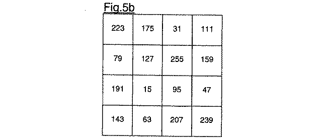
プロセスカラーの分解画像に関連した印刷信号は、画素毎に、関連したプロセスカラーの画像濃度値をラスタの対応するセル内の閾値と比較することにより生成される。ラスタはマトリクス構造の繰り返しパターンである。マトリクスの各セルのサイズは、印刷ユニットによって描画できる最小画像ドットサイズに対応する。16個のセルを有するこのようなマトリクス構造の一例は図5aに示されている。実際には、通常、より多数の色調値を描画することができる一層大きいマトリクスが使用される。最小画像濃度と最大画像濃度の間の閾値の分布は選択することができる。閾値は所定の順序で、又は、ランダムに並べられてよい。 The print signal associated with the separation image of the process color is generated on a pixel-by-pixel basis by comparing the image density value of the associated process color with a threshold in the corresponding cell of the raster. A raster is a repeating pattern of a matrix structure. The size of each cell of the matrix corresponds to the minimum image dot size that can be drawn by the printing unit. An example of such a matrix structure having 16 cells is shown in FIG. 5a. In practice, usually larger matrices are used that can render a larger number of tonal values. The threshold distribution between the minimum and maximum image densities can be selected. The thresholds may be arranged in a predetermined order or randomly.
更に、一例として、図5aにおける単一のマトリクス構造のラスタと同じサイズのエリアを有するデジタル画像(図5cを参照)が処理され、その画像部分が画素と対応している場合を考える。第1のディザマトリクス(図5a)の最大閾値は255である。この場合には画素である画像部分の総エリアカバレッジ値(CT)は、それぞれのプロセスカラーの画像濃度値を加算することにより得られた値に基づいている。画像濃度値の合計が255を上回るとき、CTは100%カバレッジを上回る。デジタル画像の第1の画像部分は、黒色だけの240である非零画像濃度値を有する画素である(図2cの左上隅)。したがって、CT値が100%カバレッジを下回ることは明らかである。即ち、図3の処理フローを使用したとき、層の数は1である。本例の場合、画像の各画素のプロセスカラーのソート系列(31)は同じであり、K、M、C、及び、最後にYの順番である。最初、DTは、プロセスカラーの系列内の1番目のプロセスカラーに関連した画像濃度値と一致する。このプロセスカラーは黒であるので、DT=240である。第1の層に関連したラスタは図5aのラスタである。DTは、関連したラスタの対応した閾値63と比較される(33)。DTの値はこの閾値を上回るので、対応した色、この場合には黒のマーキング粒子の画像ドットを形成することが指示される。これは図5fに現されている(左上隅)。この一連のステップは、後続の画素に対して繰り返される。各層内で、同じラスタが各プロセスカラーのため使用される。図5fの空のセルは、形成される画像ドットが存在しないことを指示する。図5cの第2行の4番目の画素は、マゼンタ色に関連した画像濃度値200と、黄色に関連した画像濃度値150と、を有する。これらの値を加算することによって、最大閾値255を明らかに上回る値350が得られ、換言すると、CTは100%を上回る(24)。画素に関連した各プロセスカラーの画像濃度値Mi、j、Yi、jは、図4を参照して詳しく説明されたように、第1の画像濃度値M1i、j、Y1i、j(図5d)と、第2の画像濃度値M2i、j、Y2i、j(図5e)と、分けられる(26)。Mi、j+Yi、j>255(44)であるとき、第1の画像濃度値M1i、j=0.57×255=145とY1i、j=0.43×255=110が計算され、第2の画像濃度値M2i、j=200−145=55とY2i、j=150−110=40が計算される(46)。印刷信号へ変換するため、図3の処理フローが再び使用される。第1の層に対し、最初、DTは、プロセスカラーの系列内の1番目のプロセスカラーに関連した画像濃度値と一致する。これは黒であるため、DT=0である。第1の層に関連したラスタは図5aのラスタである。DTは、関連したラスタの対応する閾値175と比較される(33)。DTの値はこの閾値よりも小さいので、プロセスカラーが系列内の最後のプロセスカラーであるかどうかが判定される(35)。プロセスカラーは黒であるため、まだその場合には当てはまらない。したがって、次のプロセスカラー(マゼンタ)に関連した画像濃度値がDTに加算される(32)。再度、ここでは145に一致するDTは、関連したラスタの同じ対応する閾値175と比較される(33)。このDTの値は未だこの閾値を上回らない。したがって、黄色プロセスカラーに対する値110がDTに加算され、DTが明らかに閾値を上回る。その結果として、図5eに示されているように、黄色の画像ドットが第1の層に形成される。第2の層に対し、最初、DTの非零値は、マゼンタ色のプロセスカラーに関連した画像濃度値55と一致する。第2の層に関連したラスタは図5bのラスタである。DTは関連したラスタの対応する閾値159と比較される(33)。DTの値はこの閾値よりも小さいので、次のプロセスカラー(黄)に関連した非零画像濃度値がDTに加算される(32)。再度、ここでは95に一致するDTが、関連したラスタの同じ対応する閾値159と比較される(33)。このDTの値は未だこの閾値を上回らない。このプロセスカラーは系列内の最後のプロセスカラーであるため、この画素に対して第2の層に画素ドットは形成されない。
Further, as an example, consider the case where a digital image (see FIG. 5c) having an area of the same size as the raster of the single matrix structure in FIG. 5a has been processed and that image portion corresponds to a pixel. The maximum threshold of the first dither matrix (FIG. 5a) is 255. In this case, the total area coverage value (CT) of the image portion which is a pixel is based on a value obtained by adding the image density values of the respective process colors. When the sum of the image density values exceeds 255, the CT is above 100% coverage. The first image portion of the digital image is the pixels having a non-zero image density value that is 240 for black only (upper left corner in FIG. 2c). Thus, it is clear that the CT value is below 100% coverage. That is, when the processing flow of FIG. 3 is used, the number of layers is one. In the case of this example, the sort sequence (31) of the process color of each pixel of the image is the same, and the order is K, M, C, and finally Y. Initially, DT matches the image density value associated with the first process color in the sequence of process colors. Since this process color is black, D T = 240. The raster associated with the first layer is that of FIG. 5a. DT is compared to the
理論的には、本例の簡単化された処理フローを利用することにより、相互に重なる同じプロセスカラーの二つの画像ドットを獲得することが可能である。しかし、実際的な実施例では、複数の層に描画される各プロセスカラーのエリアカバレッジ割合の間の比が影響されないことを保証し、かつ、各色の適切な量が描画されることを保証すると同時に、二つの画像ドットが獲得されることを避けるために、適切な注意が払われる。 Theoretically, by using the simplified processing flow of the present example, it is possible to obtain two image dots of the same process color that overlap each other. However, in a practical embodiment, ensuring that the ratio between the area coverage percentages of each process color rendered on multiple layers is not affected, and ensuring that the appropriate amount of each color is rendered At the same time, proper care is taken to avoid acquiring two image dots.
更に、本発明の他の実施例によれば、図6は、1画素のサイズを有する画像部分に関連した画像信号を、CTの値に依存してマーキング粒子の画像ドットの層を形成する印刷信号に変換する実施態様を示す図である。本発明によれば、複製された画像のカラーバランスに有利な影響を与えるため、少なくとも2色のプロセスカラーのエリアカバレッジ割合の間の比が層と層の間で変化する量を最小限に抑えるように中間調処理を行うことが目標とされる。したがって、どのプロセスカラーが第1の画像ドット層においてだけ描画されるべきかと、どのプロセスカラーがすべての層において描画されるべきかが決定される(61)。図6のような実施態様の場合、本例では黒、マゼンタ、シアン及び黄であるすべてのプロセスカラーは、すべての層に描画されることとなる。画素に関連したすべての画像濃度値の合計Σは、総エリアカバレッジ値CT、各々のプロセスカラー割合、及び、画素を描画するために必要な層の数を計算するため決定される。各層には、関連したスクリーン、即ち、閾値を含む繰り返しマトリクス構造のラスタがある。画素を描画するために多数の層が必要になる場合、即ち、CTが100%を上回るとき、各層に関連した対応するマトリクス構造は相互に異なる。必須要件ではないが、説明の簡単化のため、マトリクス構造の最大閾値TMAXは、各層に関連した対応するスクリーンに対して同一であると仮定する。一例として、CTは100%を上回ることにする。第1の層から始めて、ΣがTMAXを上回るかどうかを判定する。CTは100%を上回るので、Σ>TMAXであり、変数FRACはTMAXと一致するようにセットされる。変数FRACは、それぞれの層に亘って、画素に関連した各色の画像濃度値の分割を容易に行うために導入される。画素に関連した画像濃度値がソートされた後、マーキング粒子の画像ドットが形成されるべきであるかどうかを判定し、形成されるべきである場合、どのプロセスカラーを使用すべきかを判定する。これは次の手順で行われる。画素の全体的な画像濃度値DTが定義される(65)。最初、DTは第1の層に対応するプロセスカラーの系列中の1番目のプロセスカラーに関連した画像濃度割合と一致する。この画像濃度割合は、対応するプロセスカラーのエリアカバレッジ割合とFRACの積として決められる。このようにすることによって、各層内のプロセスカラーの画像濃度割合の間の比がほぼ同じになるという利点が得られる。1番目のプロセスカラーは黒であるため、DT=FK×FRACである。各層に関連したラスタは、2次元マトリクス構造の繰り返しパターンにより構成される。各層内で、同じラスタが各プロセスカラーに対し使用される。DTは、関連したラスタの閾値Txi、jと比較される(66)。DTの値がこの閾値を上回るとき、本例では黒である対応する色のマーキング粒子の画像ドットを形成すべきである旨を指示する(67)。DTの値がこの閾値以下であるとき、このプロセスカラーが系列中の最後のプロセスカラーであるかどうかを判定する(68)。プロセスカラーは黒であるため、このプロセスカラーは未だ最後のプロセスカラーではない。したがって、次のプロセスカラー(マゼンタ)に関連した画像濃度割合がDTに加算される(65)。再度、DTは、関連したラスタの同じ対応する閾値と比較される(66)。DTの値がこの閾値を上回るとき、対応する色、この場合には、マゼンタのマーキング粒子の画像ドットを形成すべきである旨を指示し、そうではないとき、次のプロセスカラー、即ち、シアンの画像濃度割合がDTに加算される。この一連のステップは、対応する色の画像ドットを形成すべき旨が指示される(67)か、又は、閾値を上回ること無く、系列中の最後のプロセスカラーに達する(68)まで繰り返される。後者の場合、形成されるべきマーキング粒子の画像ドットが存在しない旨を指示する(69)。本例では、CTは、特定のプロセスカラーに対し、閾値及び対応する画像濃度割合の値に依存して100%を上回るので、画像ドットを形成すべき旨が指示される。画素に関連したすべてのプロセスカラーの全エリアカバレッジ割合の合計であるFTOTは、次に、特定の着色ドットが形成されるように補正される(67)。第2又は後続の層を処理するとき、再度、その層又は各層に対して、Σの新しい値がTMAXを上回るかどうかが判定される。換言すると、例えば、第2の層の場合には、CTが200%を上回るかどうか、又は、例えば、第3の層の場合には、CTが300%を上回るかどうかが判定される。それぞれの層のマーキング粒子の画像ドットが形成されるべきであるかどうかを判定し、形成されるべきである場合に、使用されるべきプロセスカラーを判定するため、DTは、第2又は任意の後続の層に対応するプロセスカラーの系列中の1番目のプロセスカラーに関連した画像濃度割合と一致するようにセットされる。しかし、1つ又は複数の後の層で描画されるプロセスカラーの画像ドットが同じ画素位置に形成される可能性は回避される。次に、DTは、第2の層又は後続の層に関連したスクリーン内の画素位置(i、j)に対応する閾値と比較される。第2又は後続の層に関連したスクリーンは、閾値を含む繰り返しマトリクス構造のラスタであり、このマトリクス構造は、第1の層に関連したスクリーンのマトリクス構造とは異なる。しかし、第2又は後続の層に関連した画素位置(i、j)に対応する閾値は、補正されたFTOTと乗算される。特に、閾値は下げられるので、前の層に描画された色とは異なるプロセスカラーの画像ドットが後の層に描画される機会が増加する。このようにすることによって、有利には、前の層に描画されるプロセスカラーが描画されるべき色の量に与える影響が考慮され、必ず適切な量の色が効率的に描画されるようにする。 Further, in accordance with another embodiment of the present invention, FIG. 6 illustrates printing an image signal associated with an image portion having a size of one pixel to form a layer of image dots of marking particles depending on the value of CT. FIG. 4 is a diagram illustrating an embodiment of converting to a signal. According to the present invention, the amount of change between the area coverage ratios of at least two process colors between layers is minimized to advantageously affect the color balance of the reproduced image. The goal is to perform halftone processing as described above. Thus, it is determined which process color is to be rendered only in the first image dot layer and which process color is to be rendered in all layers (61). In the case of the embodiment as in FIG. 6, all process colors, in this example black, magenta, cyan and yellow, will be rendered on all layers. The sum す べ て of all image density values associated with a pixel is determined to calculate the total area coverage value CT, the percentage of each process color, and the number of layers required to render the pixel. Each layer has an associated screen, a raster of a repeating matrix structure containing thresholds. When multiple layers are required to render a pixel, i.e., when CT is greater than 100%, the corresponding matrix structures associated with each layer are different from each other. Although not a requirement, for simplicity of explanation, it is assumed that the maximum threshold T MAX of the matrix structure is the same for the corresponding screen associated with each layer. As an example, let the CT be greater than 100%. Starting from the first layer, determine if Σ is greater than T MAX . Since CT is greater than 100%, Σ> T MAX and the variable FRAC is set to match T MAX . The variable FRAC is introduced to facilitate the division of image density values for each color associated with a pixel across each layer. After the image density values associated with the pixels have been sorted, it is determined whether image dots of the marking particles are to be formed, and if so, which process color is to be used. This is performed in the following procedure. An overall image density value DT for the pixel is defined (65). Initially, DT matches the image density percentage associated with the first process color in the sequence of process colors corresponding to the first layer. This image density ratio is determined as the product of the area coverage ratio of the corresponding process color and FRAC. This has the advantage that the ratio between the image density ratios of the process colors in each layer is approximately the same. Since the first process color is black, D T = F K × FRAC. The raster associated with each layer is constituted by a repeating pattern of a two-dimensional matrix structure. Within each layer, the same raster is used for each process color. DT is compared to the associated raster threshold Txi, j (66). When the value of DT exceeds this threshold, it indicates that image dots of marking particles of the corresponding color, in this example black, should be formed (67). If the value of DT is less than or equal to this threshold, it is determined whether this process color is the last process color in the sequence (68). Since the process color is black, this process color is not yet the last process color. Therefore, the image density ratio associated with the next process color (magenta) is added to DT (65). Again, DT is compared to the same corresponding threshold of the associated raster (66). When the value of DT exceeds this threshold, it indicates that an image dot of the corresponding color, in this case, magenta marking particles, should be formed; otherwise, the next process color, ie, The cyan image density ratio is added to DT . This sequence of steps is repeated until an indication is made to form an image dot of the corresponding color (67) or the last process color in the sequence is reached (68) without exceeding the threshold. In the latter case, it is indicated that there is no image dot of the marking particles to be formed (69). In this example, the CT is greater than 100% for a particular process color, depending on the threshold and the corresponding image density ratio value, so an indication is provided that an image dot should be formed. FTOT , which is the sum of all area coverage percentages of all process colors associated with the pixel, is then corrected to form a particular colored dot (67). When processing the second or subsequent layer, it is again determined for that or each layer whether the new value of 上 回 る is greater than T MAX . In other words, it is determined, for example, whether the CT is greater than 200% for the second layer, or whether the CT is greater than 300% for the third layer, for example. DT is a second or optional value to determine whether image dots of the marking particles of each layer are to be formed and, if so, the process color to be used. Is set to match the image density ratio associated with the first process color in the sequence of process colors corresponding to the subsequent layer of. However, the possibility that image dots of the process color drawn in one or more subsequent layers are formed at the same pixel position is avoided. Next, DT is compared to a threshold corresponding to the pixel location (i, j) in the screen associated with the second or subsequent layer. The screen associated with the second or subsequent layer is a raster of a repeating matrix structure including thresholds, which is different from the matrix structure of the screen associated with the first layer. However, the threshold corresponding to the pixel position (i, j) associated with the second or subsequent layer is multiplied by the corrected F TOT . In particular, since the threshold value is lowered, the chance that image dots of a process color different from the color drawn on the previous layer are drawn on the later layer is increased. Doing so advantageously takes into account the effect of the process color drawn on the previous layer on the amount of color to be drawn, and ensures that the proper amount of color is drawn efficiently. I do.
1 画像処理システム
2 印刷ユニット
3 スキャナ
4 カメラ又はビデオカメラ
5 デジタル画像又は文書
6 プロセスカラー
7 プロセスカラー選択
8 画像信号生成器
9 変換モジュール
10 解析モジュール
20、45 画像信号
21 画像部分
22 画素
24、33、42、63、66 比較ステップ
23、65 加算ステップ
25 生成ステップ
26 スプリットステップ
31 ソートステップ
32 規定ステップ
34、36、43、67、69 指示ステップ
35、44、68 判定ステップ
46 計算ステップ
41、61 決定ステップ
Mi、j、Yi、j、M2i、j、Y2i、j画像濃度値
DESCRIPTION OF
Claims (8)
前記デジタル多色画像の各画像部分について総エリアカバレッジ値CTを決定するため、前記各画像部分について前記画像部分における画素のプロセスカラーのすべての前記画像濃度値を合計するステップと、
を有し、
ある画像部分の総エリアカバレッジ値が100%を上回る場合、
a)前記画像信号によって指定された前記画像部分の画素の前記画像濃度値を、マーキング粒子の画像ドットの第1の層に関連付けられた第1の画像濃度値と、マーキング粒子の画像ドットの第2の層及び後続の層に関連付けられた少なくとも第2の画像濃度値とに分割するステップであって、前記少なくとも第2の画像濃度値の合計をCT=100%に一致するエリアカバレッジの値に対応させる、分割するステップと、
b)マトリクスディザ技術を用いて、前記画像信号を、対応する第1の印刷信号及び対応する少なくとも第2の印刷信号に変換するステップであって、前記印刷信号のそれぞれは、画像部分の各画素に対し、対応するプロセスカラーのマーキング粒子の画像ドットを形成すべきであるかを示す信号であり、前記マトリクスディザ技術は、前記第1の印刷信号のそれぞれを前記第1の画像濃度値を閾値処理することによって第1の2次元マトリクス構造のラスタから構築し、一方、前記第2の印刷信号のそれぞれを前記第2の画像濃度値を閾値処理することによって前記第1の2次元マトリクス構造とは異なる第2の2次元マトリクス構造のラスタから構築するような技術である、変換するステップとを更に備える、デジタル多色画像を画像処理する方法。 An image signal for selecting a process color, the image signal being associated with a digitally decomposed image of the process color according to the selection of the process color and specifying an image density value of the process color associated with each pixel of the digital multicolor image. Generating from the digital multicolor image;
Summing all the image density values of the process colors of the pixels in the image portion for each image portion to determine a total area coverage value CT for each image portion of the digital multicolor image;
Has,
If the total area coverage value of a certain image part exceeds 100%,
a) determining the image density value of the pixel of the image portion specified by the image signal by a first image density value associated with a first layer of image dots of the marking particles; Dividing the sum of the at least second image density values into an area coverage value corresponding to CT = 100%. Corresponding, splitting;
b) using a matrix dither technique to convert the image signal into a corresponding first print signal and a corresponding at least a second print signal, wherein each of the print signals is a pixel of an image portion. A signal indicating whether image dots of marking particles of the corresponding process color should be formed, and the matrix dithering technique sets each of the first print signals to a threshold value of the first image density value. Processing from the rasters of the first two-dimensional matrix structure, while processing each of the second print signals with the first two-dimensional matrix structure by thresholding the second image density value. Transforming the digital multicolor image, which is a technique for constructing from a raster of a different second two-dimensional matrix structure. How to.
前記第1のプロセスカラーの前記第1のエリアカバレッジ割合と前記第2のプロセスカラーの前記第1のエリアカバレッジ割合との間の比と、前記第1のプロセスカラーの前記第2のエリアカバレッジ割合と前記第2のプロセスカラーの前記第2のエリアカバレッジ割合との間の比との差が5%未満になるような分割が行われる、請求項2に記載の方法。 Determining a first area coverage ratio of a first one of the at least two process colors based on the associated first image density value, based on the associated second image density value; Determining a second area coverage ratio of the first process color, and determining a first area coverage of a second one of the at least two process colors based on the associated first image density value; Determining a ratio and determining a second area coverage ratio of the second process color based on the associated second image density value;
The ratio between the first area coverage ratio of the first process color and the first area coverage ratio of the second process color, and the second area coverage ratio of the first process color 3. The method of claim 2, wherein the splitting is performed such that a difference between a ratio between the second process color and the second area coverage ratio of the second process color is less than 5%.
前記デジタル多色画像の各画像部分について総エリアカバレッジ値CTを決定するため、前記各画像部分について前記画像部分における画素の前記プロセスカラーのすべての前記画像濃度値を合計し、ある画像部分の総エリアカバレッジ値が100%を上回る場合、画像信号によって指定された画像部分の画素の画像濃度値を、マーキング粒子の画像ドットの第1の層に関連付けられた第1の画像濃度値と、マーキング粒子の画像ドットの第2の層及び後続の層に関連付けられた少なくとも第2の画像濃度値とに分割し、前記少なくとも第2の画像濃度値の合計をCT=100%に一致するエリアカバレッジ値に対応させる解析モジュールと、
CTが100%を上回る場合に、マトリクスディザ技術を用いて、前記画像信号を、対応する第1の印刷信号及び対応する少なくとも第2の印刷信号に変換する変換モジュールであって、前記印刷信号のそれぞれは、画像部分の各画素に対し、対応するプロセスカラーのマーキング粒子の画像ドットを形成すべきであるかを示す信号であり、前記マトリクスディザ技術は、前記第1の印刷信号のそれぞれを前記第1の画像濃度値を閾値処理することによって第1の2次元マトリクス構造のラスタから構築し、一方、前記第2の印刷信号のそれぞれを前記第2の画像濃度値を閾値処理することによって前記第1の2次元マトリクス構造とは異なる第2の2次元マトリクス構造のラスタから構築するような技術である、変換モジュールとを備える、デジタル多色画像を処理する画像処理システム。 An image signal for selecting a process color, the image signal being associated with a digitally separated image of the process color resulting from the selection of the process color, and specifying an image density value of the associated process color for each pixel of the digital multicolor image. A generation module for generating a signal from the digital multicolor image;
To determine a total area coverage value CT for each image portion of the digital multicolor image, sum the image density values of all of the process colors of pixels in the image portion for each image portion, and If the area coverage value is greater than 100%, the image density value of the pixel in the image portion specified by the image signal is replaced by the first image density value associated with the first layer of the marking particle image dots; Divided into at least a second image density value associated with a second layer of image dots and a subsequent layer of the image dots, and summing the at least second image density values to an area coverage value that matches CT = 100% Analysis modules to be supported,
A conversion module for converting the image signal into a corresponding first print signal and a corresponding at least a second print signal using a matrix dither technique when CT is greater than 100%, the conversion module comprising: Each is a signal indicating, for each pixel of the image portion, whether an image dot of a marking particle of the corresponding process color should be formed, and the matrix dither technique converts each of the first print signals to The first image density value is constructed from a raster of a first two-dimensional matrix structure by thresholding the first image density value, while each of the second print signals is thresholded by the second image density value. A conversion module, which is a technique for constructing from a raster of a second two-dimensional matrix structure different from the first two-dimensional matrix structure. Image processing system for processing a digital multi-color image.
Applications Claiming Priority (1)
| Application Number | Priority Date | Filing Date | Title |
|---|---|---|---|
| EP02080674 | 2002-12-10 |
Publications (2)
| Publication Number | Publication Date |
|---|---|
| JP2004188973A true JP2004188973A (en) | 2004-07-08 |
| JP4620948B2 JP4620948B2 (en) | 2011-01-26 |
Family
ID=32479788
Family Applications (1)
| Application Number | Title | Priority Date | Filing Date |
|---|---|---|---|
| JP2003390488A Expired - Fee Related JP4620948B2 (en) | 2002-12-10 | 2003-11-20 | Multicolor image processing system and method |
Country Status (4)
| Country | Link |
|---|---|
| US (1) | US7321447B2 (en) |
| JP (1) | JP4620948B2 (en) |
| AT (1) | ATE331388T1 (en) |
| DE (1) | DE60306324T2 (en) |
Cited By (1)
| Publication number | Priority date | Publication date | Assignee | Title |
|---|---|---|---|---|
| JP2014508441A (en) * | 2011-01-12 | 2014-04-03 | オセ−テクノロジーズ ビーブイ | Half-correlation method with semi-correlation |
Families Citing this family (12)
| Publication number | Priority date | Publication date | Assignee | Title |
|---|---|---|---|---|
| JP2005286999A (en) * | 2004-03-05 | 2005-10-13 | Fuji Photo Film Co Ltd | Allocation method of threshold matrix |
| JP2005252893A (en) | 2004-03-05 | 2005-09-15 | Fuji Photo Film Co Ltd | Threshold matrix |
| JP2005252888A (en) | 2004-03-05 | 2005-09-15 | Fuji Photo Film Co Ltd | Method for generating threshold matrix and threshold matrix thereof, and reproducing method of color image |
| JP2006092400A (en) * | 2004-09-27 | 2006-04-06 | Fuji Photo Film Co Ltd | Program for supporting digital image printing, apparatus for supporting digital image printing, and digital image printing system |
| JP4241632B2 (en) * | 2005-01-25 | 2009-03-18 | 富士フイルム株式会社 | Color plate creation threshold value matrix creation method, color image reproduction method, color image separation creation device, and threshold matrix |
| FR2891891B1 (en) * | 2005-10-11 | 2013-08-30 | Valeo Vision | OPTICALLY GUIDED LIGHTING OR SIGNALING DEVICE FOR MOTOR VEHICLE |
| JP4238902B2 (en) * | 2006-09-04 | 2009-03-18 | 日本電気株式会社 | Character noise elimination device, character noise elimination method, character noise elimination program |
| JP4707636B2 (en) * | 2006-09-26 | 2011-06-22 | 大日本スクリーン製造株式会社 | Image recording method and image recording apparatus |
| JP5121535B2 (en) * | 2008-03-31 | 2013-01-16 | キヤノン株式会社 | Image processing apparatus and method |
| JP2012186770A (en) * | 2011-03-08 | 2012-09-27 | Fuji Xerox Co Ltd | Image processing apparatus, image forming apparatus, and program |
| CN107077760B (en) | 2014-10-08 | 2020-09-08 | 惠普发展公司有限责任合伙企业 | Generating halftone data for three-dimensional objects |
| EP3213148B1 (en) | 2014-10-29 | 2021-01-13 | Hewlett-Packard Development Company, L.P. | Three-dimensional halftoning |
Citations (1)
| Publication number | Priority date | Publication date | Assignee | Title |
|---|---|---|---|---|
| JPH02155674A (en) * | 1988-12-08 | 1990-06-14 | Canon Inc | Image data processor |
Family Cites Families (12)
| Publication number | Priority date | Publication date | Assignee | Title |
|---|---|---|---|---|
| EP0162963B1 (en) * | 1984-04-27 | 1989-03-08 | Siemens Aktiengesellschaft | Ink-writing apparatus reproducing multicolour characters and/or patterns |
| US5107349A (en) * | 1990-04-16 | 1992-04-21 | Eastman Kodak Company | Multiple screen frequency half-toning with one screen angle |
| US5493323A (en) | 1993-08-05 | 1996-02-20 | Xerox Corporation | Color images having multiple separations with minimally overlapping halftone dots |
| JP2921787B2 (en) * | 1995-06-23 | 1999-07-19 | キヤノン株式会社 | Recording medium and image forming method using the same |
| US5631748A (en) | 1995-11-16 | 1997-05-20 | Xerox Corporation | Color images having multiple separations with minimally overlapping halftone dots and reduced interpixel contrast |
| US6404510B1 (en) * | 1997-05-28 | 2002-06-11 | Fuji Photo Film Co., Ltd. | Image printing method |
| US6084689A (en) * | 1998-03-11 | 2000-07-04 | Colorbus, Inc. | Method and apparatus for saturation compensation in total ink limited output |
| US6250733B1 (en) * | 1998-11-23 | 2001-06-26 | Xerox Corporation | Color printer halftoning method |
| US6307645B1 (en) | 1998-12-22 | 2001-10-23 | Xerox Corporation | Halftoning for hi-fi color inks |
| US6867884B1 (en) | 2000-07-07 | 2005-03-15 | Kodak Polychrome Graphics, Llc | Halftone dot placement for multi-color images |
| US6493083B2 (en) * | 2000-12-15 | 2002-12-10 | Xerox Corporation | Method for measuring color registration and determining registration error in marking platform |
| US6906736B2 (en) * | 2002-02-19 | 2005-06-14 | Polaroid Corporation | Technique for printing a color image |
-
2003
- 2003-11-20 JP JP2003390488A patent/JP4620948B2/en not_active Expired - Fee Related
- 2003-11-27 AT AT03078755T patent/ATE331388T1/en not_active IP Right Cessation
- 2003-11-27 DE DE60306324T patent/DE60306324T2/en not_active Expired - Lifetime
- 2003-12-09 US US10/730,118 patent/US7321447B2/en not_active Expired - Fee Related
Patent Citations (1)
| Publication number | Priority date | Publication date | Assignee | Title |
|---|---|---|---|---|
| JPH02155674A (en) * | 1988-12-08 | 1990-06-14 | Canon Inc | Image data processor |
Cited By (1)
| Publication number | Priority date | Publication date | Assignee | Title |
|---|---|---|---|---|
| JP2014508441A (en) * | 2011-01-12 | 2014-04-03 | オセ−テクノロジーズ ビーブイ | Half-correlation method with semi-correlation |
Also Published As
| Publication number | Publication date |
|---|---|
| ATE331388T1 (en) | 2006-07-15 |
| US20040114168A1 (en) | 2004-06-17 |
| DE60306324T2 (en) | 2007-06-06 |
| JP4620948B2 (en) | 2011-01-26 |
| DE60306324D1 (en) | 2006-08-03 |
| US7321447B2 (en) | 2008-01-22 |
Similar Documents
| Publication | Publication Date | Title |
|---|---|---|
| US7839537B2 (en) | Method and apparatus for multi-color printing using a rosette or diamond halftone screen for one or more of the colors | |
| JP4620948B2 (en) | Multicolor image processing system and method | |
| EP1741284A1 (en) | Hybrid dot-line halftone composite screens | |
| US10071564B2 (en) | Control apparatus, image processing method and non-transitory recording medium storing image processing program | |
| US5689344A (en) | Mitigation of tenting deletions in color xerographic printers | |
| US7508557B2 (en) | System and method for processing a multi-colour image | |
| US5633990A (en) | Method of non-overlapping color printing | |
| JP4138576B2 (en) | Method and system for processing multicolor images | |
| US7440141B2 (en) | Method for generating a dither mask | |
| EP1443748B1 (en) | System and method for processing a multi-colour image | |
| US7529005B2 (en) | Method for processing a multi-colour image | |
| US7394572B2 (en) | Method and apparatus for processing of half-tone image | |
| EP1571828B1 (en) | System and method for processing a multi-colour image | |
| JPH06113113A (en) | Image forming device | |
| EP1571827B1 (en) | Method for processing a multi-colour image | |
| EP1370067B1 (en) | Method and system for processing a multi-colour image | |
| US8294952B2 (en) | Memory efficient hierarchical error diffusion with color consistency constraints | |
| EP1608146B1 (en) | Method for generating a dither mask | |
| JP3314196B2 (en) | Image processing apparatus and method | |
| JP4396112B2 (en) | Image forming apparatus and control method thereof | |
| JP2004228941A (en) | Image processing method | |
| JP2005094293A (en) | Image forming method |
Legal Events
| Date | Code | Title | Description |
|---|---|---|---|
| A621 | Written request for application examination |
Free format text: JAPANESE INTERMEDIATE CODE: A621 Effective date: 20061116 |
|
| A131 | Notification of reasons for refusal |
Free format text: JAPANESE INTERMEDIATE CODE: A131 Effective date: 20100323 |
|
| A601 | Written request for extension of time |
Free format text: JAPANESE INTERMEDIATE CODE: A601 Effective date: 20100617 |
|
| A602 | Written permission of extension of time |
Free format text: JAPANESE INTERMEDIATE CODE: A602 Effective date: 20100622 |
|
| A521 | Request for written amendment filed |
Free format text: JAPANESE INTERMEDIATE CODE: A523 Effective date: 20100921 |
|
| TRDD | Decision of grant or rejection written | ||
| A01 | Written decision to grant a patent or to grant a registration (utility model) |
Free format text: JAPANESE INTERMEDIATE CODE: A01 Effective date: 20101012 |
|
| A01 | Written decision to grant a patent or to grant a registration (utility model) |
Free format text: JAPANESE INTERMEDIATE CODE: A01 |
|
| A61 | First payment of annual fees (during grant procedure) |
Free format text: JAPANESE INTERMEDIATE CODE: A61 Effective date: 20101029 |
|
| FPAY | Renewal fee payment (event date is renewal date of database) |
Free format text: PAYMENT UNTIL: 20131105 Year of fee payment: 3 |
|
| R150 | Certificate of patent or registration of utility model |
Ref document number: 4620948 Country of ref document: JP Free format text: JAPANESE INTERMEDIATE CODE: R150 Free format text: JAPANESE INTERMEDIATE CODE: R150 |
|
| R250 | Receipt of annual fees |
Free format text: JAPANESE INTERMEDIATE CODE: R250 |
|
| R250 | Receipt of annual fees |
Free format text: JAPANESE INTERMEDIATE CODE: R250 |
|
| R250 | Receipt of annual fees |
Free format text: JAPANESE INTERMEDIATE CODE: R250 |
|
| R250 | Receipt of annual fees |
Free format text: JAPANESE INTERMEDIATE CODE: R250 |
|
| R250 | Receipt of annual fees |
Free format text: JAPANESE INTERMEDIATE CODE: R250 |
|
| R250 | Receipt of annual fees |
Free format text: JAPANESE INTERMEDIATE CODE: R250 |
|
| LAPS | Cancellation because of no payment of annual fees |