JP2004171865A - Card connector - Google Patents
Card connector Download PDFInfo
- Publication number
- JP2004171865A JP2004171865A JP2002334972A JP2002334972A JP2004171865A JP 2004171865 A JP2004171865 A JP 2004171865A JP 2002334972 A JP2002334972 A JP 2002334972A JP 2002334972 A JP2002334972 A JP 2002334972A JP 2004171865 A JP2004171865 A JP 2004171865A
- Authority
- JP
- Japan
- Prior art keywords
- cover
- card
- housing
- card connector
- pair
- Prior art date
- Legal status (The legal status is an assumption and is not a legal conclusion. Google has not performed a legal analysis and makes no representation as to the accuracy of the status listed.)
- Pending
Links
Images


Classifications
-
- G—PHYSICS
- G06—COMPUTING OR CALCULATING; COUNTING
- G06K—GRAPHICAL DATA READING; PRESENTATION OF DATA; RECORD CARRIERS; HANDLING RECORD CARRIERS
- G06K7/00—Methods or arrangements for sensing record carriers, e.g. for reading patterns
- G06K7/0013—Methods or arrangements for sensing record carriers, e.g. for reading patterns by galvanic contacts, e.g. card connectors for ISO-7816 compliant smart cards or memory cards, e.g. SD card readers
- G06K7/0021—Methods or arrangements for sensing record carriers, e.g. for reading patterns by galvanic contacts, e.g. card connectors for ISO-7816 compliant smart cards or memory cards, e.g. SD card readers for reading/sensing record carriers having surface contacts
- G06K7/003—Methods or arrangements for sensing record carriers, e.g. for reading patterns by galvanic contacts, e.g. card connectors for ISO-7816 compliant smart cards or memory cards, e.g. SD card readers for reading/sensing record carriers having surface contacts means for pressing the connector contacts in the direction of the card contacts to assure trustworthy electrical connection between card and connector
-
- G—PHYSICS
- G06—COMPUTING OR CALCULATING; COUNTING
- G06K—GRAPHICAL DATA READING; PRESENTATION OF DATA; RECORD CARRIERS; HANDLING RECORD CARRIERS
- G06K7/00—Methods or arrangements for sensing record carriers, e.g. for reading patterns
- G06K7/0013—Methods or arrangements for sensing record carriers, e.g. for reading patterns by galvanic contacts, e.g. card connectors for ISO-7816 compliant smart cards or memory cards, e.g. SD card readers
- G06K7/0021—Methods or arrangements for sensing record carriers, e.g. for reading patterns by galvanic contacts, e.g. card connectors for ISO-7816 compliant smart cards or memory cards, e.g. SD card readers for reading/sensing record carriers having surface contacts
-
- H—ELECTRICITY
- H01—ELECTRIC ELEMENTS
- H01R—ELECTRICALLY-CONDUCTIVE CONNECTIONS; STRUCTURAL ASSOCIATIONS OF A PLURALITY OF MUTUALLY-INSULATED ELECTRICAL CONNECTING ELEMENTS; COUPLING DEVICES; CURRENT COLLECTORS
- H01R12/00—Structural associations of a plurality of mutually-insulated electrical connecting elements, specially adapted for printed circuits, e.g. printed circuit boards [PCB], flat or ribbon cables, or like generally planar structures, e.g. terminal strips, terminal blocks; Coupling devices specially adapted for printed circuits, flat or ribbon cables, or like generally planar structures; Terminals specially adapted for contact with, or insertion into, printed circuits, flat or ribbon cables, or like generally planar structures
- H01R12/70—Coupling devices
- H01R12/82—Coupling devices connected with low or zero insertion force
- H01R12/83—Coupling devices connected with low or zero insertion force connected with pivoting of printed circuits or like after insertion
Landscapes
- Engineering & Computer Science (AREA)
- Artificial Intelligence (AREA)
- Computer Vision & Pattern Recognition (AREA)
- Physics & Mathematics (AREA)
- General Physics & Mathematics (AREA)
- Theoretical Computer Science (AREA)
- Coupling Device And Connection With Printed Circuit (AREA)
- Details Of Connecting Devices For Male And Female Coupling (AREA)
Abstract
Description
【0001】
【発明の属する技術分野】
本発明は、携帯型電話機等の携帯機器に用いるカードコネクタの技術に関する。
【0002】
【従来の技術】
携帯機器のうち例えば携帯型電話機には、加入者識別情報の他に、電話番号、または着信音のメロディ情報等を記憶できる記憶用のメモリICカードが備えられている。このメモリICカードは、携帯型電話機本体に取り付けられたICカード接続用コネクタ(以下「カードコネクタ」と称する)に対して挿抜可能であり、カードコネクタにメモリICカードを挿入するとその中に記憶されている情報を利用することができる。
【0003】
このため例えば携帯型電話機を新規電話機と交換した場合でも利用者はメモリICカードに新たに情報の書込みや書換えを行う必要はない。すなわち、新規電話機の動作環境を整備する必要がないので便利である。
【0004】
カードコネクタは、基台となるハウジングと、このハウジングに対して開閉し、開いたときに開口部からカードを挿抜可能なカバーとを備えている(例えば特許文献1参照)。
【0005】
【特許文献1】
特開2000−48879号公報。
【0006】
【発明が解決しようとする課題】
前記特許文献1に記載のカードコネクタは、ハウジングからカバーが外れないことを前提として作られている。よって、万一カバーが外れた場合には、ハウジングにカバーを再装着するのは面倒であった。
【0007】
また、これまでの技術では、カードコネクタに装着されたカードがロック状態にあるか否かを確認する手立てがなかった。このため、従来のカードコネクタにあっては、ロックが不完全であることに起因して不用意にカバーが開いてしまうこともあった。
【0008】
本発明は、上記実情に鑑みて為されたものであり、その解決しようとする課題は、カバーの脱落時の再装着が容易であり、またカバーが回動しえる状態、及びカバーが閉じられてロックされた状態にあることが容易に確認できる技術を提供することにある。
【0009】
【課題を解決するための手段】
上記した課題を解決するために、本発明は以下の手段とした。
【0010】
即ち、本発明のカードコネクタは、基台となるハウジングと、このハウジングに対してスライドし、スライド方向所定の位置で回動自在に開閉し、開状態にある時にカードを挿抜可能なカバーと、このカバーの一端に形成されて当該カバーを前記ハウジングに支持する一対の支持片と、当該一対の支持片にそれぞれ形成され同一軸線上に位置する凸部と、前記ハウジングの両側部にそれぞれ形成され前記凸部と嵌合する一対の凹部と、前記凸部を前記一対の凹部のうちの一方の凹部から他方の凹部に移動すると、前記他方の凹部及び前記凸部の嵌合により前記カバーを前記ハウジングに対して回動する回動機構と、前記凸部が前記他方の凹部から前記一方の凹部に移動すると、前記一方の凹部及び前記凸部の嵌合を契機に前記カバーを閉状態でロックするロック機構とを有する。
【0011】
本発明のカードコネクタにあっては、ハウジングに取り付けられたカバーをスライドさせることで、カバーをハウジングに対して回動する回動機構と、カバーをハウジングに対して閉状態でロックするロック機構とを切り換えられるので、例えばスライド方向における一方向にカバーをスライドすればカバーはロックされるようになり、他方向にスライドすればカバーは回動できるようになるよう設定しておき、そのことを利用者に認識させておく。なおロックされる側へのスライド及び回動できる側へのスライドが一旦なされた後は、反対方向へのスライドしかできないようにしておけば、利用者は、予めわかっていたカバーのスライド方向と現在可能なスライド方向とから、カバーが現在ロック状態にあるのか回動可能状態にあるのかを認識できる。
【0012】
また、本発明のカードコネクタは、回動用凹部またはロック用凹部と嵌合する凸部を一対の支持片にそれぞれ備えたため、凸部がハウジングの側面に乗り上げると、当該乗り上げた分、即ち凸部の高さ分一対の支持片が湾曲し、一対の支持片はその変形量に応じて弾性エネルギーを蓄えるようになる。このため、一対の支持片は、その凸部が凹部と嵌入する際には、蓄積されていた弾性エネルギーが一気に放出されるようになるので、凸部が凹部に嵌入する際にクリック感(節度感)のある嵌合が得られる。よって、カバーがハウジングに対してロック解除されたか否かを利用者に認識させることができる。
【0013】
さらに、本発明のカードコネクタによれば、ハウジングに形成されている凹部と、カバーの一対の支持片にそれぞれ形成されている凸部との嵌合により、ハウジングとカバーとは一体化されている。
【0014】
そして、凸部の形成されている一対の支持片は、それぞれが曲がり易い一端固定多端自由な支持片であるからハウジングからカバーが外れてしまった場合には、一対の支持片の間を拡開することでカバーをハウジングに容易に再装着できる。
【0015】
さらにまた、前記一対の支持片の形状をそれぞれが対向する側、すなわちカバーの内側に曲折されたクランク形状にすれば、前記カバーをスライドすることにより前記凸部が回動用の他方の凹部とロック用の一方の凹部との間を移動する際に、前記凸部が前記ハウジングの側板に乗り上げた場合における、その乗り上げ量に起因して上記一対の支持片が弾性変形しても、上記一対の支持片同士の間の最大拡開幅がカバーの幅員内に収まるように凸部の高さ寸法と一対の支持片の長さ寸法を設定しておけば、ハウジングに対するカバー挿抜にあたって周囲の部品に一対の支持片が当たってしまうこともないため作業性が良好になる。
【0016】
加えて、凸部及び前記凹部を円錐形にしておけば、凸部を凹部のどこからでも入れられるので、一層作業性は良くなる。前記凸部及び前記凹部はそれぞれ扁平円形凸部及び扁平円形凹部であってもよい。
【0017】
また凹部及び凸部は、円錐形に限られるものでなく、これ以外にも、例えば扁平円形凸部及び扁平円形凹部にすることもできる。
【0018】
そして、前記ロック用の一方の凹部の一部を切り欠いておけば、これがロック用の凹部であることを視認できるので、目視によっても前記回動用の他方の凹部と簡単に区別が付けられる。よって、スライド方向の間違いを防止し易くなる。
【0019】
また、カバーを金属製にするとともに横断面(長手方向に対して直角な方向に切断した面のこと)で下方に向いたコの字状、すなわち左右上方の三方で閉塞し下方で開口する形状にし、当該横断面の左方に位置する左閉塞壁及び右方に位置する右閉塞壁の各自由端部をそれぞれ対向する側に鋭角で屈曲せしめて前記各閉塞壁に鈍角な屈曲部を形成し、この屈曲部をカード挿抜時にカードを案内するカード案内部にすることもできる。このようにすることでカバーにカードを挿入した時に前記カード案内部はカードの主面(以下カード主面)に対して異なった向きとなって対面しないので非接触状態になる。
【0020】
カバーは板金を加工して形成され、またカード主面には電気端子であるコンタクトが配置されている。しかし、このようにカード案内部がカード主面と非接触状態にあれば、カード案内部が前記コンタクトと接触しようにも両者は向きが異なっておりかつ離れているので、ショートすることが無い。カード案内部がコンタクトと接触しなければ、前記コンタクトをカードの外周近傍にまで配置することも可能になる。よって、それだけカードにおけるコネクタの設計の自由度を高められる。
【0021】
前記カバーは、その長手方向における前端及び後端にそれぞれ対向片を形成し、その内の一方の対向片に、カバーに差し込まれたカードを他方の対向片側に付勢する板バネを設けるようにしてもよい。
【0022】
この場合、カードがカバーに入れられると、一方の対向片に形成された板バネの弾性力によりカードは他方の対向片の側に押しやられ、カードの反挿入側の端部は他方の対向片に弾発的に当接するようになる。このため、カードは板バネと他方の対向片との間に挟まれるようになるので、カバーから外れ難くなる。
【0023】
また、ハウジングの前記両側部のうち前記他方の凹部形成箇所、すなわちカバーをハウジングに対して回動する回動機構を構成する箇所の上面部を円弧形状にすると共に当該上面部の曲率中心と、前記円形な他方の凹部の中心とを同じにしてもよい。
【0024】
このようにすることで、前記一方の対向片をカバーに備えなくともカードを備えたカバーの回動ができる。詳しくは、カバーが前記一方の対向片を有しないと、カバーを開いた状態、すなわちカバーが傾いた状態では、カバー内のカードは、重力により後退し、その後端縁が、カバーから突出しその結果前記上面部に当接するようになる。
【0025】
そして当該当接状態でカバーを回動しても、既述のごとく前記上面部の曲率中心と前記他方の凹部の中心(当該凹部に嵌合する前記凸部が形成された前記支持片を有するカバーの回動中心)とは同じ点で共通であるから、カバーの回動によりカバーを少し開いたことに起因してカードがカバー内を後方に移動し、もってハウジングの前記両側部のうち前記他方の凹部形成箇所の上面部にカードの後端縁が当接した後は、当該当接状態を維持しつつ、カバーの開閉に合わせてカードは前記上面部を時計回りに又は反時計回りに滑ることが可能になる。この結果、既述のように一方の対向片をカバーに設けなくてもカードを備えたカバーの回動を支障なくできる。
【0026】
加えて、前記一対の凹部の形成箇所と前記凸部の形成箇所とを入れ替えて、前記凸部を前記ハウジングの両側部にそれぞれ形成し、前記一対の凹部を前記一対の支持片にそれぞれ形成することも考えられる。このようにすることにより設計の自由度が高まる。
【0027】
【発明の実施の形態】
以下、図面を参照し、本発明であるカードコネクタの実施の形態(以下「実施形態」という)を説明する。
(第1の実施の形態)
【0028】
図1から図22を参照して本発明に係る第1の実施の形態(以下「第1実施形態」)を説明する。
【0029】
図1に示すように、カードコネクタ1は、メモリICカード(以下「ICカード」と称する)2を例えば携帯型電話機3に取り付けるための装置であって、この実施形態では、携帯型電話機3の筐体3aに形成した取付凹部3bに取り付けた状態を示す。
【0030】
カードコネクタ1は、例えば図2に示すように、カード2を挿抜可能な金属製のカバー20と、カバー20の基台であり、かつモールド成型されたハウジング10とを有する。
【0031】
カバー20は、例えば図1〜図4からわかるようにカード2よりも短い。またカバー20とハウジング10とはほぼ同じ長さ寸法である。
【0032】
また、カバー20は、例えば図5,図6,図8及び図9からわかるように、横断面でほぼコ字形を呈する。すなわちカバー20は、カード2が挿入された時にカードの表裏面であるカード主面(図2参照)を覆う主面部21と、主面部21の両側縁から垂下してカード2の左右側面を覆う左右閉塞壁22l,22r(図3参照)とを有する。なおカード主面を符号2c,2cで示し、その内、電気端子であるコンタクト30のある側の主面を便宜上符号2c’を用いて示し、コンタクト30のない側の主面2cと区別する。
【0033】
さらに、カバー20はハウジング10の長手方向に対してスライドし、スライド方向所定の位置でハウジング10に対して自在に 回動する。詳しくは、カバー20は、左右閉塞壁22l,22rの一部としてそれらの後端に延在され、カバー20の長手方向(カード2の挿抜方向)に延びる一端固定他端自由な板状をした一対の支持片24,24を有し、これら一対の支持片24,24の自由端部を結ぶ仮想の軸線を回動中心軸としてハウジング10に対してカバー20が回動することで開閉する。
【0034】
なお、本明細書において前後とは、カバー20のうちカード2が挿抜される開口20aの側が前であり、その反対側が後である。また、左右とは、カバー20の開口20aに正対して右と左の側をいう。そして上下とは、カバー20の開口20aに正対して上と下の側をいう。
【0035】
各一対の支持片24は、カバーの内側に曲折するクランク形状をしている。そして、その後端部24aはほぼ円形であり、そこには円錐形凸部24bがプレス成形されている。各一対の支持片24の円錐形凸部24b同士を結んだ線が前記軸線であり符号24cで示す(図3,図5参照)。よって各円錐形凸部24bは、カバー20の一端縁に平行な同一の軸線24c上に位置する。また、一対の支持片24がカバーの内側に曲折されたクランク形状をしている関係で、例えば図3に示すように、後端部24a同士の間隔W1は、カバーの幅員W2よりも狭い。
【0036】
さらにカバー20は、図1,図5,図6,図8,図9からわかるように、左右閉塞壁22l,22rの前端部下縁においてカバー20の内側に直角に折り曲げられた左右のカード案内部25l,25rを有する。
【0037】
カード案内部25l,25rは、図8に示すように、矩形状をした板部の一隅を切り落としたごとき板状部であり、カード2をカバー20に対して挿抜する時にカード2をカバー20内に案内し易くするとともに、カバー20の回動時、カード2がカバー20の下方に位置した時にカード2がカバー20から落下しないようにするためのものである。
【0038】
カバー20にカード案内部25l,25rを設けることにより、カバー20の主面部21と、左右閉塞壁22l,22rと、カード案内部25l,25rとから画成され、かつ下方に開口する空間部Sは断面チャネル(溝)状になる。よって、カード2はその主面2c’の一部を除きカバー20により囲繞されるとともにカード案内部25l,25rを有するので、カバー20に対してカード2の挿抜がし易くなる。
【0039】
また例えば図2,図4,図5及び図9等からわかるように、左右閉塞壁22l,22rの長手方向には、適度の間隔をあけて内側にわずかに曲折された横断面L字形の爪部26を二つ有する。爪部26は、カバー20を閉じたときにハウジング10に係止してカバー20の閉状態を維持するためのものである。
【0040】
次に、ハウジング10について説明する。
【0041】
図10に示すように、ハウジング10は、その全体形状が概略板状をしており、カバー20を閉じたときにカード2と携帯型電話機3とを電気的に接続する。当該電気的な接続を実行するためにハウジング10は複数(この実施形体では6本)のコンタクト11を有する。
【0042】
コンタクト11は、ハウジング10の中央に位置し、ほぼ中央で曲折されてU字形状をしている。コンタクト11は、ハウジング10に取り付けられた時に上側に位置し、カード2のコンタクト30と電気的に接触するカード側接点部11aと、同下側に位置し携帯型電話機3の図示しないコンタクトと電気的に接触する電話機側接点部11bとからなる。また、コンタクト11をこのようにU字形にした関係で、カバー20を閉じた時に弾性力を生じる。この弾性力は、カバー20を閉じた時にコンタクト11がカード2の前記コンタクトと確実に接触するように作用する。
【0043】
板状のハウジング10は、コンタクト11が配置される矩形状のコンタクト配置部10Aと、コンタクト配置部10Aの両側に位置しかつコンタクト配置部10Aよりも後方に延びる一対のカバー取付け腕10a,10aとからなる。カバー取付け腕10aはハウジング10の側部といえる。
【0044】
コンタクト配置部10Aは、その中央に前記コンタクト11を収納する複数(この実施形形体では6つ)の収納溝が左右前後に整列して形成されており、これら各溝内でコンタクト11が保持される。
【0045】
カバー取付け腕10aは、横断面が矩形の柱形状をしている。そして、カバー取付け腕10aの後端部10a1に支持された状態で、カバー20が回動したりスライドしたりする。
【0046】
カバー取付け腕10aは、その後端部10a1の外側面における前後方向(長手方向)に配列されかつ隣接する2つの凹部12,13を有する。なお、この明細書では、凹部12,13を便宜上それぞれ他方の凹部および一方の凹部として取り扱う。他方の凹部12よりも他方の凹部13の方が前方に位置する。後端部10a1はカバー取付け腕10aの他の部位よりも大きめなほぼ直方体形状をした部位である。
【0047】
凹部12は、この凹部12にカバー20の円錐形凸部24bが嵌合することでカバー20をハウジング10に対して回動する回動機構20Aを構成する円錐形凹部である。よって凹部12を特に断らない限り回動用円錐凹部12という。
【0048】
凹部13は、カバー20の閉状態をロックする際に円錐形凸部24bと嵌合し、当該嵌合を契機にカバー20をハウジング10に対して閉状態でロックする、後述のロック機構20Bを機能させる。よって凹部13をロック用円錐凹部13という。
【0049】
また、カバー取付け腕10aは、その外側面の長手方向における略中央部にカバー20の爪部26が挿入される爪部挿入凹部14A,14Bを有する。
【0050】
爪部挿入凹部14Aは、上方,下方及び側方に開いており、その前部には、爪部挿入凹部14Aに爪部26が挿入された際に爪部26と係止してカバー20の閉状態を保持する爪部係止部14aを有する。
【0051】
爪部挿入凹部14Aのうち爪部係止部14a以外の部位では、爪部26は係止されずに解放された状態になる。よって、当該部位を爪部解放部と呼称し符号14bで示す。このような爪部挿入凹部14Aは、その側面形状が矩形の四隅のうちの一隅部を矩形に除去したごとき形状である。
【0052】
爪部係止部14aと爪部26とは、共に前記ロック機構20Bの構成部材である(図4,図18,図20参照)。図4に示すように、爪部係止部14aの爪部解放部14bに爪部26を入れた後、カバー20をハウジング10の長手方向における前方にスライドすることで爪部26を爪部係止部14aに係止させると、カバー20のハウジング10に対する閉状態が維持される。
【0053】
そして、その状態から爪部26が爪部解放部14bに位置するようにカバー20をハウジング10の長手方向における後方にスライドすると、爪部26と爪部係止部14aとの前記係止が解かれるため、カバー20を開けるようになる。
【0054】
爪部挿入凹部14Bは、爪部挿入凹部14Aとほぼ同じであるが、相違点は、後方に開いている点と、カバー20のスライド方向に応じて、爪部26を爪部係止部14aや爪部解放部14bに案内するガイド部14cを有することである。
【0055】
爪部挿入凹部14Bが後方にも開いているのは、爪部挿入凹部14Bのさらに後方に他の爪部挿入凹部がないからである。この関係で、爪部挿入凹部14Bに係る爪部解放部14bは、爪部挿入凹部14Aに係る爪部解放部14bよりも大きい。
【0056】
次にカバー20のハウジング10への取り付けについて述べる。
【0057】
カバー20をハウジング10に取り付けるには、カバー20の一対の支持片24,24をハウジング10の幅寸法よりも拡開する(図11,図12参照)。そして、図12に示すように、一対の支持片24の後端部24aに形成されている円錐形凸部24bをハウジング10の回動用円錐凹部12の近傍に当接させた後、図13に示すように回動用円錐凹部12に向けて(図11〜13の例示では上から下に向けて)カバー20を移動して嵌合する。当該嵌合により、カバー20をハウジング10に対して回動する前記回動機構20Aが形成される。なお、カバー20の円錐形凸部24bをハウジング10のロック用円錐凹部13に嵌合しても、カバー20をハウジング10に対して回動することはそれ自体可能であるが、正規な回動位置ではないので完全にカバー20を閉じることができないようになっている。このため、カバー20のハウジング10に対する回動を確保するためには、カバー20のハウジング10への取り付けにあたり、円錐形凸部24bを回動用円錐凹部12に確実に嵌合することを要する。
【0058】
回動機構20Aにより、カバー20はハウジング10に対して、軸線24cを回動軸として時計回りに又は反時計回りに回動できるようになる。そしてカバー20を回動することによってカバー20がハウジング10から離れた状態にある時には、カバー20に対するカード2の挿抜ができる。そして、当該状態にカバー20があるときをこの明細書ではカバー20が開いた状態にあるという。
【0059】
反対に開状態にあるカバー20がハウジング10に向けて回動することで、両者20,10が、重なり合った状態をカバー20が閉じた状態にあるという。当該閉状態でロック機構20Bが機能すると、カバー20はハウジング10に対して開かなくなり、カバー20に対するカード2の抜き差しができなくなる。
【0060】
次にカバー20が回動機構20Aによる回動可能状態からロック機構20Bによりロックされるまでの状態および反対にカバー20がロックされた状態から回動できるようになるまでの状態を詳説する。
【0061】
図2は、ロック機構20Bによりカバー20がハウジング10にロックされて開かない状態を示す。当然ながらこのとき、円錐形凸部24b及びロック用円錐凹部13は嵌合状態にある。
【0062】
ロック機構20Bによるロック状態を解除して非ロック状態にするには、図2〜図4の矢印A方向にカバー20をスライドする。すると、それまで嵌合状態にあった円錐形凸部24bとロック用円錐凹部13との嵌合が解かれて、図14及び図15に示すように、円錐形凸部24bは、ロック用円錐凹部13と回動用円錐凹部12との間の狭間部15に乗り上げる。
【0063】
円錐形凸部24bが狭間部15に乗り上げると、一対の支持片24は自由端部である後端部24aが外側に幾分変位し、支持片24全体でわずかに外側に湾曲せしめられる。ただし、その変位量は、カバー20の幅員W2内に収まるように、一対の支持片24の長さ寸法や円錐形凸部24bの高さ寸法が設定されている。また一対の支持片24が湾曲しているとき、一対の支持片24には弾性エネルギーが蓄えられる。
【0064】
さらにカバー20を矢印A方向にスライドすると、それまで爪部係止部14aにあった爪部26が爪部解放部14bに変位する(図18参照)。このため、ロック機構20Bによるカバー20のロックは解除される。また、ロック解除前にロック用円錐凹部13と嵌合していた円錐形凸部24bは、ロック用円錐凹部13との嵌合が解かれて回動用円錐凹部12と嵌合する。
【0065】
円錐形凸部24bの回動用円錐凹部12との嵌合にあたり、湾曲により一対の支持片24に蓄積されていた弾性エネルギーは一気に開放されて一対の支持片24は変形前の元の状態に戻る。この結果、円錐形凸部24bが回動用円錐凹部12に衝突する。よって、利用者はクリック感(節度感)を覚えるため、カバー20がロック解除されたか否かを認識できる。当該クリック感は、円錐形凸部24bがロック用円錐凹部13と嵌合する場合にも同様に認識できる。
【0066】
円錐形凸部24bと回動用円錐凹部12との嵌合により、回動機構20Aが機能するようになる。
【0067】
カードコネクタ1は、図4の状態にあっては、既述のようにカバー20はロック状態にあるのでカバー20は開かない。
【0068】
また図16〜図19は、図4の状態からカバー20をハウジング10に対してその長手方向における後方にスライドすることで、回動機構20Aによりカバー20を図4において時計回りに開くことができる状態にあることを示す。なお図19は図18の状態にあるカードコネクタの適所で切った縦断面図であり、ハウジング10のU字形をしたコンタクト11のカード側接点部11aと電話機側接点部11bとが閉じた状態にあり、その状態でカード2のコンタクト30(図1参照)とハウジング10のコンタクト11とが当接状態にあることを示す。
【0069】
図20は、図18の状態からカバー20を鋭角状態で開くことにより、カード2の挿入が矢印C方向において可能であり、矢印D方向においてカード2を抜くことが可能であることを示す。図21は鋭角に開いた状態にあるカードコネクタを適所で切った縦断面図である。カバー20を開いた状態ではハウジング10のコンタクト11がその弾性により拡開した状態にあることがわかる。
【0070】
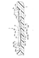
図22は、カバー20を鈍角状態で開きカバー20を携帯型電話機3の筐体3aに当接させた状態でもカード2の挿抜が矢印C及びD方向にできる状態にあることを示す。
【0071】
開いた状態のカバー20を閉じるときは、図22においてカバー20を時計回りに回動する。
【0072】
カバー20にカード2を挿入後カバー20を閉じると、ハウジング10のコンタクト11とカード2のコンタクト30とが接触し、もってカードコネクタ1とカード2との電気的接続がなされ、カードコネクタ1を介して携帯型電話機3とカード2との間で情報のやりとりが可能になる。
【0073】
このような構成の第1の実施形態に係るカードコネクタ1にあっては、次のような作用効果を奏する。
【0074】
カード2をカードコネクタ1のカバー20に収納し、カバー20を閉じる方向に回動して閉じた後、携帯型電話機3の筐体3aに形成した取付凹部3b内において図2や図4等で示した矢印B方向にカバー20をハウジング10に対してスライドすると、カバー20はロック機構20Bによってロックされた状態になる(図4参照)。なお、この状態でカード2のうちカード2が差し込まれる側と反対側の端縁である前端縁2aが、携帯型電話機3の筐体3aの内壁面3a1に当接する程近接するように、前記取付凹部3bにおけるカードコネクタ1の長さ寸法やカバー20のスライド量等を設定しておけば、カバー20からのカード2の抜けを確実に防止できる。
【0075】
さらに、カードコネクタ1によれば、ハウジング10に形成されている回動用円錐凹部12と、カバー20の一対の支持片に形成されている円錐形凸部24bとの嵌合によりハウジング10とカバー20とは一体化されているけれども、円錐形凸部24bは、曲がり易い一端固定他端自由な一対の支持片24に形成されているので、ハウジング10からカバー20が外れてしまった場合には、一対の支持片24,24の間を拡開することでカバー20をハウジング10に容易に装着することができる。
【0076】
さらにまた、前記一対の支持片24,24はその形状がカバー20の内側に曲折されたクランク形状であるから、カバー20をハウジング10に対してスライドすることで円錐形凸部24bがハウジング10の側板のうち回動用円錐凹部12とロック用円錐凹部13との間の狭間部15を移動する際に、円錐形凸部24bが当該狭間部15に乗り上げた際のその乗り上げ量に起因して一対の支持片24,24が拡開する方向に湾曲しても、一対の支持片24,24同士の間の最大拡開幅がカバー20の幅員W2内に収まるように円錐形凸部24bの高さ寸法と一対の支持片24,24の長さ寸法を設定してあるので、ハウジング10に対するカバー20の挿抜にあたって周囲の部品に湾曲した一対の支持片24が当たってしまうことはない。したがって作業性が良好である。
【0077】
加えて、円錐形凸部24b及び回動用円錐凹部12が錐形状であるから、円錐形凸部24bを回動用円錐凹部12のどこからでも入れられる。よって、カードコネクタ1にあってはその組み立て作業性が良好になる。円錐形はその斜面の傾きを任意に設計できるため、円錐形凸部24b及び回動用円錐凹部12の嵌合時の外れにくさと、カバー20をハウジング10に対してスライドした時のカバー20の操作性を考慮した最適な傾きを選択できるので設計の自由度が広がる。
【0078】
なお、カバー20を図7に示すように変形することもできる。図7は図6に相当する横断面図である。
【0079】
図7に係るカバー20は、下方を向いたコの字状すなわち左右上方の三方で閉塞し下方で開口する形状をしている。そしてカバー20の、横断面における自由端縁を外側から内側に向けて鋭角で折り曲げて鈍角な屈曲部25’l,25’rを形成し、当該屈曲部25’l,25’rを、カード挿抜時にカード2を案内するカード案内部にしてある。
【0080】
図7より、カード案内部25’l,25’rがカード2のコンタクト30が設けられている側のカード主面2c’と非接触状態にあることがわかる。要するに第1の変形例にあってはカード案内部の曲げ角度が相違する。
【0081】
カバー20は金属製であり、またカード2の主面2c’には電気端子であるコンタクト30が配置されている。しかし、このようにカード案内部25’l,25’rがカード主面2c’と非接触状態にあれば、カード案内部25’l,25’rがカード主面2c’にあるコンタクト30と接触しようにも、カード案内部25’l,25’rとコンタクト30とは離れており、接触できないようになっているのでショートすることがない。
【0082】
カード案内部25’l,25’rがコンタクト11と接触しなければ、コンタクト30をカード2の中心部に限定することなく外周近傍にも配置することも可能になる。よって、それだけカード2におけるコンタクト30の設計の自由度を高められる。
【0083】
また、図9に図2のIX−IX線に沿って切断した一部省略断面図を示す。
【0084】
爪部26がコンタクト30に当接しないように、左右閉塞壁22l,22rの長さ寸法をカード2の厚みよりも大きくすると好適である。
(第2の実施の形態)
【0085】
図23から図28を参照して本発明カードコネクタの第2の実施の形態(以下「第2実施形態」)を説明する。本実施形態のカードコネクタを符号1Aで示す。
【0086】
第2実施形態に係るカードコネクタ1Aが第1実施形態に係るカードコネクタ1と異なる点は、ハウジング10に形成されている回動機構とロック機構の形態である。よって他の同一部分には同一符号を付して説明を省略する。
【0087】
第1実施形態に係る回動機構では、回動用の凹部がロック用の凹部よりも後方にあったが、本実施形態では逆であり、回動用凹部がロック用凹部よりも前方にある。また、ロック用凹部の形状は開口が半円状の切欠円錐状であり、その形成位置は図24に示すように、切り欠き側が後方を向いた状態で、カバー取付け腕10aの後端部10a1の外形線にまで臨むようになっている。一方、回動用凹部は円錐形である。本実施形態に係る回動用凹部及びロック用凹部をそれぞれ符号12Aおよび13Aで示す。また、回動機構及びロック機構をそれぞれ符号20A’及び20B’で示す。
【0088】
また、本実施形態では、カバー取付け腕10aの長手方向において回動用凹部12Aがロック用凹部13Aよりも前方に位置する関係上、ロック機構の爪部係止部は、その形成箇所が爪部挿入凹部の後方に位置する。本実施形態では爪部係止部および爪部解放部をそれぞれ符号14a’および14b’で示し、爪部挿入凹部を符号14A’,14B’で示す。また、爪部挿入凹部14A’に係る爪部解放部14b’の方が,爪部挿入凹部14B’に係る爪部解放部14b’よりも大きく、この点第1の実施形態の場合と逆である。
【0089】
次に図25〜図28を参照して、本実施形態の作用効果を説明する。
【0090】
図25及び図26はカバー20のロック状態を示し、図27及び図28はカバー20の非ロック(回動可能)状態を示し、それぞれカバー20の回動前の状態及び回動している状態を示す。
【0091】
カバー20を非ロック状態にするには、カバー20を図26の矢印B方向にスライドする。すると、それまで嵌合状態にあった円錐形凸部24bとロック用凹部13Aとの嵌合が解かれて、カバー20の円錐形凸部24bは、ロック用凹部13Aと回動用円錐凹部12Aとの間にある狭間部15に乗り上げる(図示せず)。
【0092】
このとき、第1実施形態と同様その乗り上げ量を含む各一対の支持片24の後端部24a同士の間隔W1は、カバー20の幅員W2内に収まるようになっている。従って、第2実施形態に係るカードコネクタ1にあっても第1実施形態の場合と同様、携帯型電話機3への設置場所の面積が限られる場合に、カードコネクタ1の周囲に確保する必要のある空間を少なくできる。
【0093】
カバー20をさらに矢印B方向にスライドさせると、図27に示すように円錐形凸部24bは、回動用凹部12Aと嵌合する。このとき、前述のように、円錐形凸部24bが回動用凹部12Aに嵌入する際にクリック感(節度感)が得られ、カバー20がハウジング10に対してロック解除されたか否かを利用者に認識させることができる。
【0094】
円錐形凸部24bと回動用凹部12Aとの嵌合により回動機構20A’を構成し、図28のようにカバー20を図27の状態から反時計回りに回動し、もってカバー20を開くことができる。
【0095】
反対にカバー20を閉じるときは、図28の状態から時計回りにカバー20を回動して図27のようにカバー20を閉じる。その後カバー20を図27の矢印A方向にスライドし、図26で示すようにロック機構20Bを作動させカバー20が開かないようにする。ロック機構20Bが確実に機能しているか否かの判断も第1実施形態の場合と同様クリック感を認識することで実現する。
【0096】
本実施形態に係るカードコネクタ1にあっては、ロック用凹部13Aが半円錐形状であるから、円錐形をした回動用凹部12Aとの形状差は歴然としている。よってカバー20をハウジング10に装着する際に、利用者はカバー20の取付位置を間違えることがない。また、カバー取付け腕10aの長手方向における前後に回動用凹部12Aとロック用凹部13Aとは配置されており、ロック用凹部13Aは、その開口が半円状の切欠円錐状でかつ切り欠き側が後方を向いているので、それだけハウジング10の長さ寸法を小さくできる。よってハウジング10、延いてはカードコネクタ1の小型化ができる。また材料の節約になる。
(第3の実施の形態)
【0097】
図29から図38を参照して本発明カードコネクタの第3の実施の形態(以下「第3実施形態」)を説明する。
【0098】
図29は本発明第3の実施形態に係るカードコネクタ1Bの全体斜視図であって、カバーを閉じた状態を示す。また、図30はカバーを開いた状態を示すカードコネクタの一部切欠斜視図であり、図31は図30の矢印IIIXI方向から見た状態でハウジング10からカバー20’を取り外した図である。さらに図32はハウジングの全体斜視図であり、図33は図32の要部拡大斜視図である。
【0099】
第3実施形態に係るカードコネクタ1Bが第2実施形態に係るカードコネクタ1Aと異なる点は、回動機構とロック機構の形態、カバー内にカードが全部収納されるようになっている点、カバーの構成、これら相違点に関連する箇所にある。よって第2実施形態と同一部分には同一符号を付して説明を省略する。
【0100】
図33のカードコネクタ1Bの要部拡大斜視図からわかるように、カードコネクタ1Bでは回動機構を構成する回動用凹部は 扁平な円形凹部であり、ロック用凹部は回動用凹部を半分にした扁平な半円形凹部である。回動用凹部及びロック用凹部をそれぞれ符号12B及び13Bで示す。
【0101】
また、回動用凹部12B及びロック用凹部13Bが扁平凹部である関係上、一対の支持片24の凸部もそれに合わせて高さは低い。当該凸部を符号24b’で示す。またこれまでの実施形態では当該凸部は円錐形であったが、回動用凹部12Bやロック用凹部13Bに合わせて扁平円柱凸部にしてもよいのは勿論である。要は凸部24b’と回動用凹部12B又はロック用凹部13Bとが好適に嵌合できればよい。また、回動用凹部12Bとロック用凹部13Bとはそれらの並び方向において二次面的に見て点接触(奥行き方向においては線接触)しているので、両凹部を離して形成した場合に比べ、ハウジング10のカバー取付け腕10aの後端部10a1の長さ寸法を短くできる。なお、両凹部を交叉させることも可能であり、この場合、後端部10a1の長さ寸法をさらに短くできる。
【0102】
また、第3実施形態に係るロック機構は、第2実施形態に係るロック機構20B’(図26,図27参照)と同種のものであるが、ロック機構を構成する爪部係止部14a’を含む爪部挿入凹部の形成位置が、矩形状のコンタクト配置部10Aの長手方向における両端部近傍にある点で異なる。なお、本実施形態では、爪部挿入凹部の形態は、その形成位置に拘わらず第2実施形態の爪部挿入凹部14B’と同一であるので同一符号を付して説明を省略する(図34参照)。
【0103】
また、第3実施形態のカバーを符号20’で示す。
【0104】
カバー20’は、その長手方向における前端及び後端にそれぞれ対向片となる、庇片27(他方の対向片)及びカード支持片28(一方の対向片)を有する。
【0105】
庇片27は、カバー20’の前端縁からカバー20’の主面部21(図29参照)に対して直角に折り曲げられた細長い板状片である。
【0106】
カード支持片28は、カバー20’の後端縁に設けられた横断面L字形をなす細長い板状片である。カード支持片28は、カバー20’の主面部21との間でカード2を挟めるように主面部21の内側に折り曲げられている。そして、カード支持片28には、カバー20’に差し込まれたカード2を庇片27側に向けて付勢する板バネ28aをカード支持片28のうちカバー20’と連結されている連結部28bに有する。板バネ28aは、連結部28bの一部をU字形に切り欠いて上方に曲折した片持ち梁状の板バネである。
【0107】
このような構成の第3の実施形態に係るカードコネクタ1Bにあっては、第1及び第2の実施形態と同様の効果を得られる以外に次のような作用効果を奏する。
【0108】
すなわち、カード2はその先端がカード支持片28と主面部21との間に入ると、板バネ28aの弾性力によりカード2は庇片27側に向けて押しやられる。このため、カード2はその両端がそれぞれ庇片27及びカード支持片28に弾発的に当接した状態になる。このため、カード2は板バネ28aと庇片27との間に挟まれるようになり、よって第1実施形態で述べたカード案内部25がなくても、当該弾発力を解除しない限りカード2はカバー20’から落下しなくなる。
【0109】
カバー20のロック及び解除の方法においては第1実施形態の場合と同様であるので、説明は省略する。
(第1変形例)
【0110】
図34〜図36を参照して第3実施形態に係る第1変形例のカードコネクタ1B’を説明する。このカードコネクタ1B’がカードコネクタ1Bと相違する点は、カード支持片に係わる箇所およびそれに関連する箇所だけである。よって、他の同一部分には同一符号を付して説明を省略する。本第1変形例のカード支持片を符号28’で示す。
【0111】
カードコネクタ1B’のカード支持片28’がカードコネクタ1Bのカード支持片28と相違する点は、片持ち梁状の弾性片28cを有する点である(図34参照)。
【0112】
片持ち梁状の弾性片28cは、カバー20’を閉じた場合にカバーを開く方向に弾性を生じる。
【0113】
すなわち弾性片28cは、カバー20’が開いているときは、図35に示すように”への字状”をしているが、カバー20’を閉じると、カバー20’とハウジング10との間で挟まれて屈曲点28c1が図36に示すように下方に変位するようになっている。このため、弾性片28cは、カバー20’が開いた状態にある時の弾性片28c(図35参照)を反転したごとき形状になり(換言すれば弾性片28cは、下方に鈍角で開いていた状態から上方に鈍角で開いた状態になる。)、カード支持片28には弾性エネルギーが蓄積されるようになる。そしてこの時にカバー20’が非ロック状態にないと当該弾性エネルギはカバー20’を開くように作用する。
【0114】
よって、この第1の変形例にあっては、当該弾性エネルギがカバー20’に作用することによりカバー20’を開き易くなるという特有の効果を奏する。
【0115】
なお、ハウジング10において弾性片28cが当接する部位には溝10bを形成してある。当該溝10bは弾性片28cに対応していればハウジング10のどこにあってもよいが、この実施形態ではコンタクト配置部10Aのうち一方(右側)のカバー取付け腕10aの近傍に形成されている。
(第2変形例)
【0116】
第2変形例に係るカードコネクタを符号1C(図37参照)で示す。
【0117】
また、図38は、カードコネクタ1Cの要部拡大斜視図である。カードコネクタ1Cが第1変形例に係るカードコネクタ1B’と相違する主要な部分は、回動用凹部及びロック用凹部及びそれに伴う関連箇所だけである。よってカードコネクタ1B’と同一部分及び他の実施形態と同一部分には同一符号を付して説明を省略する。
【0118】
本変形例に係る回動用凹部12B’及びロック用凹部13B’が、第1変形例に係る回動用凹部12B及びロック用凹部13B(図33参照)と相違する点は、(1)前者の回動用凹部12B’にあっては、図33に示す円形の回動用凹部12Bにその中心点Cを交叉する仮想十字線C1の垂直線に沿って延びる扁平な縦溝(以下「扁平溝」と」称す)16をカバー取付け腕10aの後端部10a1に形成した点、(2)後者のロック用凹部13B’にあっては、その形成箇所及び形状がロック用凹部13Bの場合と異なる点にある。
【0119】
また、これら(1)及び(2)の相違に基づいて、カードコネクタ1Cにあっては、(3)ハウジング両側部である一対のカバー取付け腕10a,10aに形成されている爪部挿入凹部の形態が相違する。
【0120】
扁平溝16は横断面で劣弧形状をした浅めな溝であり、回動用凹部12B’に一対の支持片24の凸部を案内する案内溝として機能する。なお、凸部24b’を扁平な円柱形状とした場合、扁平溝16の溝幅もそれに合わせて拡大することで、凸部24b’が溝16内を通過できるようにすると好適である。
【0121】
なお、扁平溝16はその横断面が劣弧形状をしたものを示したがこれに限定されないのは勿論である。要するに、回動用凹部12B’に一対の支持片24の凸部24b’を案内できる形状をした溝であればなんでもよい。
【0122】
扁平溝16は、既述した各種実施形態にも適用できる。
【0123】
ロック用凹部13B’は、回動用凹部12B’の前方に形成され図38に示した状態で、前方上部が90°切り欠かれた一部切欠き円形状の凹部である。
【0124】
本第2変形例にあっては、回動用凹部12B’の前方にロック用凹部13B’があるので、第1実施形態で述べた場合と同様、爪部係止部14a,爪部解放部14b及びガイド部14cを有する一対の爪部挿入凹部14Bが一対のカバー取付け腕10a,10aに形成されている(図37参照)。
【0125】
この第2変形例の場合も既述した第2実施形態の場合と同様、ロック用凹部13B’が切り欠かれておりそのことが視認できるので、目視によっても前記回動用凹部12B’と簡単に区別が付けられる。よって、スライド方向の間違いを防止し易くなる。また、回動用凹部12B’とロック用凹部13B’とはそれらの並び方向において二次面的に見て点接触(奥行き方向においては線接触)しているので、両凹部12B’,13B’を離して形成した場合に比べ、ハウジング10のカバー取付け腕10aの後端部10a1の長さ寸法を短くできる。よって材料の節約ができる。
【0126】
さらに、回動用凹部12B’に支持片24の凸部24b’を案内する案内溝として扁平溝16が機能するので、扁平溝16に支持片24の凸部24b’を当てた状態で、回動用凹部12B’に向けて凸部24b’を滑らせれば回動用凹部12B’に支持片24の凸部24b’が自動的に嵌合するようになる。よって回動用凹部12B’と凸部24b’との嵌合を確実に行える。
【0127】
また、図38に示すように、カバー取付け腕10aの後端部10a1の上面部10a11の形状が横断面で円弧形状であり、その曲率中心(曲率半径R)と回動用凹部12B’の中心(曲率半径r)とは同じである。当該中心を符号Cで示す。
【0128】
このようにすることで、カード支持片28’をカバー20’に備えなくともカード2を備えたカバー20’の回動ができる。詳述すると、カバー20’がカード支持片28’を有しないと、カバー20’を開いた状態、すなわちカバー20’が傾いた状態では、カバー内のカード2は、重力により後退し、その後端縁2bが、カバー20’の後方から突出し、その結果前記上面部10a11に当接するようになる。
【0129】
そして当該当接状態でカバー20’を回動しても、既述のごとく後端部10a1の上面部10a11の曲率中心と回動用凹部12B’の中心、すなわち当該凹部12B’に嵌合する前記凸部24b’が形成された前記支持片24を有するカバー20’の回動中心とは既述のごとく同じ点Cで共通であるから、カバー20’の回動によりカバー20’を少し開くことに起因してカード2がカバー20’内を後方に移動し、もってハウジング10の前記一対のカバー取付け腕10a,10aのうち、回動用凹部12B’が形成されている箇所の上面部10a11にカード2の後端縁2bが当接した後は、当該当接状態を維持しつつ、カバー20’の開閉に合わせてカード2は前記上面部10a11を時計回りに又は反時計回りに滑ることが可能になる(図39,図40参照)。この結果、既述のようにカード支持片28’をカバー20’に設けなくてもカード2を備えたカバー20’の回動が支障なくできる。
【0130】
このように、ハウジングのカバー取付け腕のうち前記他方の凹部形成箇所の上面部の外形線を円弧形状にすると共に当該上面部の曲率中心と、前記円形な他方の凹部の中心とを同じにするという技術的思想は、既述した他の実施形態にも適用できる。
【0131】
例えば、わかりやすい例で、ハウジングのカバー取付け腕のうち前記他方の凹部形成箇所の上面部の外形線が丸みを帯びている図24に示す本発明第2実施形態に係るハウジング10に適用した場合を図41を参照して述べると、ハウジング10のカバー取付け腕10aのうち前記他方の凹部12A形成箇所の上面部10a11の曲率中心と、前記円形な他方の凹部12Aの中心とを同じにすることで適用できる。これらは共通であるので符号Cで示す。
【0132】
なお、回動用凹部12B’と凸部24b’とが嵌合してなる本変形例に係る回動機構を符号20A”で示す。なお、本第2変形例にあってはロック機構には第1実施形態に係るロック機構20Bが適用されている。
【0133】
また、前記した各実施形態で述べた一対の凹部12,13、12A,13A,13B,12B’,13B’の形成箇所である一対のカバー取付け腕10a,10aと、これらの凹部12,13、12A,13A,13B,12B’,13B’に対応する前記凸部24bや24b’の形成箇所である前記一対の支持片24,24とを入れ替えて、前記凸部24bや24b’を一対のカバー取付け腕10aに形成し、前記凹部12,13、12A,13A,13B,12B’,13B’を前記一対の支持片に形成してもよい。このようにすることで設計の自由度が高まる。
【0134】
【発明の効果】
以上、説明したように本発明のカードコネクタによれば、万が一カバーがハウジングから外れた場合でもカバーの脱落時の再装着が容易にできるので作業性が向上する。またハウジングの両側部に一対の凹部を設け、カバーには前記凹部と嵌合する凸部を設けて凹凸嵌合可能とし、当該凹凸嵌合の利用によって、カバーがハウジングに対して回動可能状態であることとロックされた状態で閉じられていることとが容易に確認できる技術を提供するという優れた効果を奏し得る。
【図面の簡単な説明】
【図1】本発明第1の実施形態に係るカードコネクタを携帯型電話機に適用した場合の一例を示す図である。
【図2】本発明第1の実施形態に係るカードコネクタにカードを挿入しカバーを閉じた状態の全体斜視図である。
【図3】図2の平面図である。
【図4】図1のIV−IV線断面図である。
【図5】本発明第1の実施形態に係るカバーの全体斜視図である。
【図6】図5の矢印VI方向から見たカバー端面図である。
【図7】本発明第1の実施形態に係る変形例であって図6に相当する図である。
【図8】本発明第1の実施形態に係るカバーの裏面図である。
【図9】図2のIX−IX線に沿って切断した一部省略断面図である。
【図10】本発明第1の実施形態に係るハウジングの全体斜視図である。
【図11】本発明第1の実施形態に係るカードコネクタの分解斜視図である。
【図12】図11の状態からカバーをハウジングに取り付ける直前の斜視図である。
【図13】図12の状態からカバーをハウジングに取り付けた状態を示す斜視図である。
【図14】図2の状態においてカバーをスライドすることで、カバーをロック状態から回動可能状態に移行する中途状態を示す斜視図である。
【図15】図14の平面図である。
【図16】図14の状態からカバーをさらにスライドして、カバーが回動可能状態に移行した状態を示す斜視図である。
【図17】図16の平面図である。
【図18】図4の状態からカバーをスライドし、回動機構によりカバーを開くことができる状態にあることを示す図である。
【図19】図18の状態におけるカードコネクタの縦断面図である。
【図20】カバーを鋭角で開きカードの挿抜ができる状態を示す図である。
【図21】鋭角状態におけるカードコネクタの縦断面図である。
【図22】カバーを鈍角状態で開きカバーを携帯型電話機の筐体に当接させた状態でカードの挿抜ができる状態を示す図である。
【図23】本発明第2の実施形態に係るカードコネクタにおいてカバーを鋭角で開いている状態を示す全体斜視図である。
【図24】本発明第2の実施形態に係るハウジングの全体斜視図である。
【図25】本発明第2の実施形態に係るカードコネクタにカードを挿入しカバーを閉じた状態の全体斜視図である。
【図26】図25の矢印IIXVI方向から見た側面図である。
【図27】図26の状態からカバーをスライドし、カバーが回動可能状態に移行した状態を示す側面図である。
【図28】図27の状態からカバーを鋭角状態で開きカードの挿抜ができる状態を示す図である。
【図29】本発明第3の実施形態に係るカードコネクタの全体斜視図であって、カバーを閉じた状態を示す図である。
【図30】本発明第3の実施形態に係るカードコネクタの一部切欠斜視図であって、カードが挿入されている状態でカバーを開いた状態を示す図である。
【図31】図30の矢印IIIXI方向から見たカバーの一部切り欠き図である。
【図32】本発明第3の実施形態に係るハウジングの全体斜視図である。
【図33】図32の領域IIIXIII部分の拡大図である。
【図34】本発明第3の実施形態に係るカードコネクタの第1の変形例を示す全体斜視図である。
【図35】図34の鈍角で開いているカバーを鋭角で開いた場合の縦断面図であって、カード支持片の弾性片を含む箇所での縦断面図である。
【図36】図35に係るカードコネクタを閉じている状態を示す縦断面図である。
【図37】本発明第3実施形態における第2の変形例に係るカードコネクタの全体斜視図である。
【図38】本発明第3実施形態における第2の変形例に係るカードコネクタの要部拡大斜視図であって図33に相当する図である。
【図39】図37のIIIXIX−IIIXIX線に沿って切断した垂直断面図である。
【図40】図39の状態からカバーを閉じた場合の垂直断面図である。
【図41】第2変形例の適用例であって図24の領域IVXI部分の拡大斜視図である。
【符号の説明】
1 カードコネクタ
1A カードコネクタ
1B カードコネクタ
1B’ カードコネクタ
1C カードコネクタ
2 カード
2a カードの前端縁
2b カードの後端縁
2c カード主面
2c’カード主面
3 携帯型電話機
3a 筐体
3a1 内壁面
3b 取付凹部
10 ハウジング
10A コンタクト配置部
10a カバー取付け腕
10a1 後端部
10a11 後端部の上面部
10b 溝
11 ハウジングのコンタクト
11a カード側接点部
11b 電話機側接点部
12 回動用円錐凹部
12A 回動用凹部
12B 回動用凹部
12B’ 回動用凹部
13 ロック用円錐凹部
13A ロック用凹部
13B ロック用凹部
13B’ロック用凹部
14A 爪部挿入凹部
14B 爪部挿入凹部
14A’ 爪部挿入凹部
14B’ 爪部挿入凹部
14a 爪部係止部
14a’ 爪部係止部
14b 爪部解放部
14b’ 爪部解放部
14c ガイド部
15 狭間部
16 扁平溝
20 カバー
20’カバー
20A 回動機構
20A’回動機構
20A”回動機構
20B ロック機構
20B’ロック機構
20a カバーの開口
21 カバーの主面部
22l カバーの左閉塞壁
22r カバーの右閉塞壁
24 一対の支持片
24a 一対の支持片の後端部
24b 円錐形凸部
24b’ 扁平凸部
24c 軸線
25 カード案内部
25l カード案内部
25r カード案内部
25’l カード案内部
25’r カード案内部
26 爪部
27 庇片
28 カード支持片
28’ カード支持片
28a 板バネ
28b 連結部
28c1 屈曲点
28c 弾性片
30 カードのコンタクト
C 回動用凹部またはカバー取付け腕の後端部上面部の中心点
C1 仮想十字線[0001]
TECHNICAL FIELD OF THE INVENTION
The present invention relates to a technology of a card connector used for a mobile device such as a mobile phone.
[0002]
[Prior art]
2. Description of the Related Art For example, a portable telephone among portable devices is provided with a memory IC card for storage capable of storing a telephone number, melody information of a ringtone, and the like in addition to subscriber identification information. The memory IC card can be inserted into and removed from an IC card connector (hereinafter, referred to as a "card connector") attached to the main body of the portable telephone. When the memory IC card is inserted into the card connector, the memory IC card is stored therein. Information that is available.
[0003]
Therefore, for example, even when the portable telephone is replaced with a new telephone, the user does not need to newly write or rewrite information in the memory IC card. In other words, there is no need to improve the operating environment of the new telephone, which is convenient.
[0004]
The card connector includes a housing serving as a base, and a cover which can be opened and closed with respect to the housing and which can insert and remove a card from an opening when opened.
[0005]
[Patent Document 1]
JP-A-2000-48879.
[0006]
[Problems to be solved by the invention]
The card connector described in
[0007]
Further, in the conventional techniques, there is no means for checking whether the card mounted on the card connector is in a locked state. For this reason, in the conventional card connector, the cover may be opened carelessly due to incomplete locking.
[0008]
SUMMARY OF THE INVENTION The present invention has been made in view of the above circumstances, and a problem to be solved is that the cover can be easily re-attached when the cover is dropped off, the cover can be rotated, and the cover is closed. It is an object of the present invention to provide a technology that allows the user to easily confirm the locked state.
[0009]
[Means for Solving the Problems]
In order to solve the above problems, the present invention has the following solutions.
[0010]
That is, the card connector of the present invention has a housing serving as a base, a cover that slides with respect to the housing, opens and closes rotatably at a predetermined position in the sliding direction, and allows a card to be inserted and removed when in an open state, A pair of support pieces formed at one end of the cover and supporting the cover to the housing, a projection formed on the pair of support pieces and positioned on the same axis, and formed on both sides of the housing, respectively. A pair of recesses to be fitted with the protrusions, and when the protrusions are moved from one of the pair of recesses to the other, the cover is fitted by fitting the other recess and the protrusions. When the protrusion moves from the other recess to the one recess, the cover closes upon the engagement of the one recess and the protrusion when the protrusion moves from the other recess to the one recess. And a lock mechanism for locking.
[0011]
According to the card connector of the present invention, a rotating mechanism for rotating the cover with respect to the housing by sliding the cover attached to the housing, and a locking mechanism for locking the cover in a closed state with respect to the housing. For example, if you slide the cover in one direction in the sliding direction, the cover will be locked, and if you slide in the other direction, the cover will be set to be able to rotate, and that is used Let people know. After the slide to the locked side and the slide to the rotatable side are performed once, if only the slide in the opposite direction can be performed, the user can determine the slide direction of the cover previously known and the current slide direction. From the possible sliding direction, it is possible to recognize whether the cover is currently in the locked state or the rotatable state.
[0012]
In addition, the card connector of the present invention includes the pair of support pieces each having a convex portion that fits into the rotation concave portion or the lock concave portion. Therefore, when the convex portion rides on the side surface of the housing, the convex portion, that is, the convex portion. The pair of support pieces are curved by the height of the pair, and the pair of support pieces store elastic energy according to the deformation amount. For this reason, when the convex portion of the pair of support pieces is fitted into the concave portion, the stored elastic energy is released at a stretch, so that a click feeling (a moderation) occurs when the convex portion is fitted into the concave portion. Feeling) can be obtained. Therefore, it is possible to make the user recognize whether or not the cover is unlocked with respect to the housing.
[0013]
Further, according to the card connector of the present invention, the housing and the cover are integrated by fitting the concave portion formed on the housing with the convex portions formed on the pair of support pieces of the cover. .
[0014]
When the cover is detached from the housing, the pair of support pieces on which the convex portions are formed are easily fixed and each end is a multi-end free support piece. By doing so, the cover can be easily reattached to the housing.
[0015]
Furthermore, if the shape of the pair of support pieces is a crank shape bent to the side facing each other, that is, the inside of the cover, the cover is slid so that the protrusion locks with the other recess for rotation. When moving between one of the concave portions, the convex portion rides on the side plate of the housing. By setting the height of the projection and the length of the pair of support pieces so that the maximum expansion width between the support pieces is within the width of the cover, the surrounding parts can be inserted and removed when inserting and removing the cover from the housing. Workability is improved because the pair of support pieces do not hit.
[0016]
In addition, if the convex portion and the concave portion are formed in a conical shape, the convex portion can be inserted from anywhere in the concave portion, so that the workability is further improved. The convex portion and the concave portion may be a flat circular convex portion and a flat circular concave portion, respectively.
[0017]
Further, the concave portion and the convex portion are not limited to the conical shape, but may be, for example, a flat circular convex portion and a flat circular concave portion.
[0018]
If a part of the one locking recess is cut out, it is possible to visually recognize that the locking recess is a locking recess, so that it can be easily distinguished visually from the other rotating recess. Therefore, it is easy to prevent a mistake in the sliding direction.
[0019]
In addition, the cover is made of metal and has a U-shape that faces downward in a cross section (a surface cut in a direction perpendicular to the longitudinal direction), that is, a shape that is closed on three sides on the left and right and opened downward. And each free end of the left obstruction wall located on the left side of the cross section and the right obstruction wall located on the right side is bent at an acute angle to the opposing side to form an obtuse bent portion in each of the obstruction walls. However, the bent portion may be used as a card guiding portion for guiding the card when inserting and removing the card. In this way, when the card is inserted into the cover, the card guide is in a different direction with respect to the main surface of the card (hereinafter referred to as the card main surface) and does not face each other, so that it is in a non-contact state.
[0020]
The cover is formed by processing a sheet metal, and contacts as electric terminals are arranged on the main surface of the card. However, if the card guide is not in contact with the card main surface as described above, even if the card guide is in contact with the contact, the two are different in direction and separated from each other, so that there is no short circuit. If the card guide does not come into contact with the contacts, the contacts can be arranged near the outer periphery of the card. Therefore, the degree of freedom in designing the connector of the card can be increased accordingly.
[0021]
The cover has opposing pieces formed at the front end and the rear end in the longitudinal direction, and one of the opposing pieces is provided with a leaf spring for urging the card inserted into the cover toward the other opposing side. You may.
[0022]
In this case, when the card is put into the cover, the card is pushed toward the other opposing piece by the elastic force of the leaf spring formed on one opposing piece, and the end of the card on the side opposite to the insertion side is put on the other opposing piece. Will come into contact with the body. For this reason, the card is sandwiched between the leaf spring and the other opposing piece, so that it is difficult for the card to come off the cover.
[0023]
Further, the upper surface portion of the other concave portion forming portion of the both side portions of the housing, that is, the upper surface portion of a portion constituting a rotating mechanism that rotates the cover with respect to the housing, and the center of curvature of the upper surface portion, The center of the other circular recess may be the same.
[0024]
By doing so, the cover provided with the card can be rotated without providing the one opposing piece on the cover. Specifically, when the cover does not have the one opposing piece, in a state in which the cover is opened, that is, in a state where the cover is inclined, the card in the cover retreats due to gravity, and the rear edge protrudes from the cover. It comes into contact with the upper surface.
[0025]
Then, even if the cover is rotated in the contact state, as described above, the center of curvature of the upper surface portion and the center of the other concave portion (including the support piece on which the convex portion fitted to the concave portion is formed). (The center of rotation of the cover) is common in the same point, so that the card is moved rearward in the cover due to the cover being slightly opened by the rotation of the cover, and the After the rear edge of the card contacts the upper surface of the other concave portion, the card rotates the upper surface clockwise or counterclockwise in accordance with opening and closing of the cover while maintaining the contact state. It becomes possible to slip. As a result, the rotation of the cover provided with the card can be easily performed without providing one of the opposed pieces on the cover as described above.
[0026]
In addition, the locations where the pair of concave portions are formed and the locations where the convex portions are formed are interchanged, the convex portions are formed on both sides of the housing, and the pair of concave portions are formed on the pair of support pieces, respectively. It is also possible. This increases the degree of freedom in design.
[0027]
BEST MODE FOR CARRYING OUT THE INVENTION
Hereinafter, an embodiment (hereinafter, referred to as “embodiment”) of a card connector according to the present invention will be described with reference to the drawings.
(First Embodiment)
[0028]
A first embodiment according to the present invention (hereinafter, “first embodiment”) will be described with reference to FIGS.
[0029]
As shown in FIG. 1, a
[0030]
The
[0031]
The
[0032]
Further, as can be seen from FIGS. 5, 6, 8 and 9, for example, the
[0033]
Further, the
[0034]
In addition, in this specification, the front and rear means the front of the
[0035]
Each pair of
[0036]
Further, as can be seen from FIGS. 1, 5, 6, 8, and 9, the right and left card guides bent at right angles to the inside of the
[0037]
As shown in FIG. 8, the
[0038]
By providing the card guides 251 and 25r on the
[0039]
As can be seen from, for example, FIGS. 2, 4, 5 and 9, etc., in the longitudinal direction of the left and
[0040]
Next, the
[0041]
As shown in FIG. 10, the
[0042]
The
[0043]
The plate-shaped
[0044]
A plurality of (six in this embodiment) storage grooves for storing the
[0045]
The
[0046]
The
[0047]
The
[0048]
The
[0049]
The
[0050]
The
[0051]
The
[0052]
The
[0053]
Then, when the
[0054]
The
[0055]
The
[0056]
Next, attachment of the
[0057]
To attach the
[0058]
The
[0059]
Conversely, when the
[0060]
Next, a state from a state in which the
[0061]
FIG. 2 shows a state where the
[0062]
To release the locked state by the
[0063]
When the conical
[0064]
When the
[0065]
Upon fitting of the conical
[0066]
The fitting of the conical
[0067]
In the state of FIG. 4, the
[0068]
16 to 19, the
[0069]
FIG. 20 shows that the
[0070]
FIG. 22 shows that the
[0071]
To close the
[0072]
When the
[0073]
The
[0074]
After the
[0075]
Further, according to the
[0076]
Further, since the pair of
[0077]
In addition, since the conical
[0078]
The
[0079]
The
[0080]
FIG. 7 shows that the card guides 25′l and 25′r are in a non-contact state with the card
[0081]
The
[0082]
If the card guides 25'l and 25'r do not contact the
[0083]
FIG. 9 is a partially omitted cross-sectional view taken along the line IX-IX of FIG.
[0084]
It is preferable that the length dimension of the left and
(Second embodiment)
[0085]
A second embodiment (hereinafter, “second embodiment”) of the card connector of the present invention will be described with reference to FIGS. The card connector of the present embodiment is denoted by
[0086]
The difference between the
[0087]
In the rotation mechanism according to the first embodiment, the concave portion for rotation is behind the concave portion for locking, but in the present embodiment, the opposite is true, and the concave portion for rotating is located forward of the concave portion for locking. The shape of the locking concave portion is a notch conical shape with a semicircular opening, and its forming position is as shown in FIG. 24, with the notch side facing rearward and the rear end portion 10a1 of the
[0088]
Further, in the present embodiment, since the rotation
[0089]
Next, referring to FIGS. 25 to 28, the operation and effect of the present embodiment will be described.
[0090]
FIGS. 25 and 26 show the locked state of the
[0091]
In order to put the
[0092]
At this time, similarly to the first embodiment, the distance W1 between the
[0093]
When the
[0094]
The
[0095]
Conversely, when closing the
[0096]
In the
(Third embodiment)
[0097]
A third embodiment of the card connector of the present invention (hereinafter, "third embodiment") will be described with reference to FIGS.
[0098]
FIG. 29 is an overall perspective view of the
[0099]
The
[0100]
As can be seen from the enlarged perspective view of the main part of the
[0101]
In addition, since the rotating
[0102]
The lock mechanism according to the third embodiment is of the same type as the
[0103]
The cover of the third embodiment is indicated by reference numeral 20 '.
[0104]
The cover 20 'has an eaves piece 27 (the other opposing piece) and a card support piece 28 (one opposing piece) which are opposing pieces at the front end and the rear end in the longitudinal direction, respectively.
[0105]
The
[0106]
The
[0107]
The
[0108]
That is, when the leading end of the
[0109]
The method for locking and releasing the
(First Modification)
[0110]
A
[0111]
The card supporting piece 28 'of the
[0112]
The cantilever-shaped
[0113]
That is, when the
[0114]
Therefore, the first modified example has a specific effect that the
[0115]
A
(Second Modification)
[0116]
The card connector according to the second modification is denoted by reference numeral 1C (see FIG. 37).
[0117]
FIG. 38 is an enlarged perspective view of a main part of the card connector 1C. The main parts of the card connector 1C that are different from the
[0118]
The difference between the turning
[0119]
Also, based on the difference between (1) and (2), in the card connector 1C, (3) the claw insertion concave portions formed on the pair of
[0120]
The
[0121]
The
[0122]
The
[0123]
The
[0124]
In the second modified example, since the
[0125]
In the case of the second modification, similarly to the case of the second embodiment described above, the
[0126]
Further, since the
[0127]
As shown in FIG. 38, the shape of the upper surface portion 10a11 of the rear end portion 10a1 of the
[0128]
By doing so, the cover 20 'provided with the
[0129]
Even if the cover 20 'is rotated in the contact state, as described above, the center of curvature of the upper surface portion 10a11 of the rear end portion 10a1 and the center of the rotation
[0130]
As described above, the outer shape line of the upper surface of the other concave portion of the cover mounting arm of the housing is formed in an arc shape, and the center of curvature of the upper surface is the same as the center of the other circular concave portion. This technical idea can be applied to the other embodiments described above.
[0131]
For example, in an example that is easy to understand, a case where the present invention is applied to the
[0132]
Note that a rotation mechanism according to this modification in which the rotation
[0133]
In addition, a pair of
[0134]
【The invention's effect】
As described above, according to the card connector of the present invention, even if the cover comes off the housing, the cover can be easily re-attached when the cover comes off, so that the workability is improved. Further, a pair of concave portions are provided on both sides of the housing, and a convex portion is provided on the cover so as to be fitted to the concave portion, so that the cover can be rotated with respect to the housing by using the concave and convex fitting. It is possible to obtain an excellent effect of providing a technology that allows the user to easily confirm that the lock is closed in a locked state.
[Brief description of the drawings]
FIG. 1 is a diagram illustrating an example in which a card connector according to a first embodiment of the present invention is applied to a mobile phone.
FIG. 2 is an overall perspective view of a state where a card is inserted into a card connector according to the first embodiment of the present invention and a cover is closed.
FIG. 3 is a plan view of FIG. 2;
FIG. 4 is a sectional view taken along line IV-IV of FIG. 1;
FIG. 5 is an overall perspective view of a cover according to the first embodiment of the present invention.
FIG. 6 is an end view of the cover as viewed from a direction of an arrow VI in FIG. 5;
FIG. 7 is a modified example according to the first embodiment of the present invention and is a view corresponding to FIG.
FIG. 8 is a rear view of the cover according to the first embodiment of the present invention.
FIG. 9 is a partially omitted cross-sectional view taken along the line IX-IX of FIG. 2;
FIG. 10 is an overall perspective view of a housing according to the first embodiment of the present invention.
FIG. 11 is an exploded perspective view of the card connector according to the first embodiment of the present invention.
FIG. 12 is a perspective view of the state of FIG. 11 immediately before the cover is attached to the housing.
FIG. 13 is a perspective view showing a state where the cover is attached to the housing from the state of FIG.
14 is a perspective view showing an intermediate state in which the cover is slid from a locked state to a rotatable state by sliding the cover in the state shown in FIG. 2;
FIG. 15 is a plan view of FIG.
FIG. 16 is a perspective view showing a state in which the cover is further slid from the state of FIG. 14 and the cover shifts to a rotatable state;
FIG. 17 is a plan view of FIG. 16;
18 is a view showing that the cover is slid from the state shown in FIG. 4 and the cover can be opened by a rotating mechanism.
19 is a longitudinal sectional view of the card connector in the state of FIG.
FIG. 20 is a view showing a state in which the cover can be opened at an acute angle to insert and remove a card.
FIG. 21 is a longitudinal sectional view of the card connector in an acute angle state.
FIG. 22 is a diagram showing a state in which a card can be inserted and withdrawn while the cover is opened at an obtuse angle and the cover is in contact with the housing of the mobile phone.
FIG. 23 is an overall perspective view showing a state in which a cover is opened at an acute angle in the card connector according to the second embodiment of the present invention.
FIG. 24 is an overall perspective view of a housing according to a second embodiment of the present invention.
FIG. 25 is an overall perspective view of a state where a card is inserted into a card connector according to a second embodiment of the present invention and a cover is closed.
26 is a side view as seen from the direction of arrow IIXVI in FIG. 25.
27 is a side view showing a state in which the cover is slid from the state shown in FIG. 26 and the cover shifts to a rotatable state.
FIG. 28 is a diagram showing a state in which the cover can be opened at an acute angle from the state of FIG. 27 so that a card can be inserted and removed.
FIG. 29 is an overall perspective view of a card connector according to a third embodiment of the present invention, showing a state in which a cover is closed.
FIG. 30 is a partially cutaway perspective view of a card connector according to a third embodiment of the present invention, showing a state where a cover is opened while a card is inserted.
31 is a partially cutaway view of the cover as viewed from the direction of arrow IIIXI in FIG. 30.
FIG. 32 is an overall perspective view of a housing according to a third embodiment of the present invention.
FIG. 33 is an enlarged view of a region IIIXIII in FIG. 32;
FIG. 34 is an overall perspective view showing a first modification of the card connector according to the third embodiment of the present invention.
FIG. 35 is a vertical cross-sectional view when the cover that is opened at an obtuse angle in FIG. 34 is opened at an acute angle, and is a vertical cross-sectional view of a portion including an elastic piece of a card supporting piece.
36 is a longitudinal sectional view showing a state where the card connector shown in FIG. 35 is closed.
FIG. 37 is an overall perspective view of a card connector according to a second modification of the third embodiment of the present invention.
38 is an enlarged perspective view of a main part of a card connector according to a second modification of the third embodiment of the present invention, and is a view corresponding to FIG. 33.
FIG. 39 is a vertical sectional view taken along the line IIIXIX-IIIXIX of FIG. 37.
40 is a vertical sectional view when the cover is closed from the state shown in FIG. 39.
FIG. 41 is an application example of the second modified example and is an enlarged perspective view of a region IVXI in FIG. 24;
[Explanation of symbols]
1 Card connector
1A card connector
1B card connector
1B 'card connector
1C card connector
2 cards
2a Front edge of card
2b Card trailing edge
2c Card main surface
2c 'card main surface
3 Mobile phone
3a housing
3a1 Inner wall
3b Mounting recess
10 Housing
10A contact arrangement part
10a Cover mounting arm
10a1 rear end
10a11 Upper surface of rear end
10b groove
11 Housing contacts
11a Card side contact
11b Telephone contact section
12 Conical recess for rotation
12A Rotating recess
12B Rotating recess
12B 'Rotating recess
13 Locking conical recess
13A Lock recess
13B Lock recess
13B 'Lock recess
14A Claw insertion recess
14B Claw insertion recess
14A 'claw insertion recess
14B 'claw insertion recess
14a Claw locking part
14a 'Claw locking part
14b Claw release section
14b 'claw release section
14c Guide part
15 Narrow section
16 flat groove
20 Cover
20 'cover
20A rotation mechanism
20A 'rotating mechanism
20A "rotating mechanism
20B Lock mechanism
20B 'lock mechanism
20a Cover opening
21 Main surface of cover
22l Left closing wall of cover
22r Right closing wall of cover
24 A pair of support pieces
24a Rear ends of a pair of support pieces
24b Conical convex
24b 'flat convex part
24c axis
25 Card Guide
25l Card Guide
25r Card guide
25'l Card guide
25'r card guide
26 Claw
27 Eaves piece
28 Card support strip
28 'card support strip
28a leaf spring
28b connecting part
28c1 Bending point
28c elastic piece
30 card contacts
C Center point of the upper surface of the rear end of the rotating recess or cover mounting arm
C1 virtual crosshair
Claims (9)
このハウジング(10)に対してスライドし、スライド方向所定の位置で回動自在に開閉し、開状態にある時にカード(2)を挿抜可能なカバー(20)と、
このカバー(20)の一端に形成されて当該カバー(20)を前記ハウジング(10)に支持する一対の支持片(24,24)と、
当該一対の支持片(24,24)にそれぞれ形成され同一軸線上に位置する凸部(24b)と、
前記ハウジング(10)の両側部(10a,10a)にそれぞれ形成され前記凸部(24b)と嵌合する一対の凹部(12,13)と、
前記凸部(24b)を前記一対の凹部(12,13)のうちの一方の凹部(13)から他方の凹部(12)に移動すると、前記他方の凹部(12)及び前記凸部(24b)の嵌合により前記カバー(20)を前記ハウジング(10)に対して回動する回動機構(20A)と、
前記凸部(24b)が前記他方の凹部(12)から前記一方の凹部(13)に移動すると、前記一方の凹部(13)及び前記凸部(24b)の嵌合を契機に前記カバー(20)を閉状態でロックするロック機構(20B)とを有するカードコネクタ(1)。A housing (10) serving as a base;
A cover (20) that slides with respect to the housing (10), opens and closes rotatably at a predetermined position in the sliding direction, and allows insertion and removal of the card (2) when in an open state;
A pair of support pieces (24, 24) formed at one end of the cover (20) and supporting the cover (20) on the housing (10);
A projection (24b) formed on the pair of support pieces (24, 24) and located on the same axis,
A pair of recesses (12, 13) formed on both sides (10a, 10a) of the housing (10) and fitted with the protrusions (24b),
When the convex portion (24b) is moved from one concave portion (13) of the pair of concave portions (12, 13) to the other concave portion (12), the other concave portion (12) and the convex portion (24b) are moved. A rotating mechanism (20A) for rotating the cover (20) with respect to the housing (10) by fitting of
When the convex part (24b) moves from the other concave part (12) to the one concave part (13), the cover (20) is triggered by the fitting of the one concave part (13) and the convex part (24b). And a lock mechanism (20B) for locking the card connector in a closed state.
その内の一方の対向片(28)は、カバー(20’)に差し込まれたカード(2)を他方の対向片(27)側に付勢する板バネ(28a)を有することを特徴とする請求項1乃至3のいずれかに記載のカードコネクタ(1B)。The cover (20 ') has opposing pieces (27, 28) at its front and rear ends in the longitudinal direction, respectively.
One of the opposing pieces (28) has a leaf spring (28a) for urging the card (2) inserted into the cover (20 ') toward the other opposing piece (27). The card connector (1B) according to any one of claims 1 to 3.
Priority Applications (7)
| Application Number | Priority Date | Filing Date | Title |
|---|---|---|---|
| JP2002334972A JP2004171865A (en) | 2002-11-19 | 2002-11-19 | Card connector |
| PCT/US2003/036952 WO2004047228A1 (en) | 2002-11-19 | 2003-11-19 | Improved memory card connector |
| AU2003297289A AU2003297289A1 (en) | 2002-11-19 | 2003-11-19 | Improved memory card connector |
| DE60311513T DE60311513T2 (en) | 2002-11-19 | 2003-11-19 | Improved memory card connector |
| EP03811633A EP1563574B9 (en) | 2002-11-19 | 2003-11-19 | improved memory card connector |
| US10/535,560 US20060270263A1 (en) | 2002-11-19 | 2003-11-19 | Memory card connector |
| CN 200380105086 CN1720643A (en) | 2002-11-19 | 2003-11-19 | Improved memory card connector |
Applications Claiming Priority (1)
| Application Number | Priority Date | Filing Date | Title |
|---|---|---|---|
| JP2002334972A JP2004171865A (en) | 2002-11-19 | 2002-11-19 | Card connector |
Publications (1)
| Publication Number | Publication Date |
|---|---|
| JP2004171865A true JP2004171865A (en) | 2004-06-17 |
Family
ID=32321746
Family Applications (1)
| Application Number | Title | Priority Date | Filing Date |
|---|---|---|---|
| JP2002334972A Pending JP2004171865A (en) | 2002-11-19 | 2002-11-19 | Card connector |
Country Status (6)
| Country | Link |
|---|---|
| EP (1) | EP1563574B9 (en) |
| JP (1) | JP2004171865A (en) |
| CN (1) | CN1720643A (en) |
| AU (1) | AU2003297289A1 (en) |
| DE (1) | DE60311513T2 (en) |
| WO (1) | WO2004047228A1 (en) |
Cited By (5)
| Publication number | Priority date | Publication date | Assignee | Title |
|---|---|---|---|---|
| JP2006210127A (en) * | 2005-01-27 | 2006-08-10 | Jst Mfg Co Ltd | Card connector |
| JP2006210128A (en) * | 2005-01-27 | 2006-08-10 | Jst Mfg Co Ltd | Card connector |
| JP2007149395A (en) * | 2005-11-24 | 2007-06-14 | Jst Mfg Co Ltd | connector |
| JP2010170862A (en) * | 2009-01-23 | 2010-08-05 | Hosiden Corp | Connector for optical wiring |
| WO2025088789A1 (en) * | 2023-10-27 | 2025-05-01 | ファナック株式会社 | Motor drive device |
Families Citing this family (7)
| Publication number | Priority date | Publication date | Assignee | Title |
|---|---|---|---|---|
| GB2406449A (en) * | 2003-09-26 | 2005-03-30 | Molex Inc | Memory Card Connector with Latch and Lock |
| JP2006085987A (en) * | 2004-09-15 | 2006-03-30 | Japan Aviation Electronics Industry Ltd | Card connector |
| US7658630B2 (en) | 2005-04-18 | 2010-02-09 | Hewlett-Packard Development Company, L.P. | System and method for connecting electronic components |
| JP5049003B2 (en) | 2006-05-25 | 2012-10-17 | 第一電子工業株式会社 | Card Connector and Housing SubAssy Manufacturing Method |
| DE102007057521B4 (en) * | 2006-11-30 | 2011-09-22 | Amphenol-Tuchel Electronics Gmbh | Smart card connector with shielding device |
| CN102738618B (en) * | 2011-04-15 | 2015-02-04 | 索尼爱立信移动通讯有限公司 | Storage card base, mobile terminal and method for protecting storage card |
| CN108258499B (en) * | 2017-12-29 | 2020-02-18 | 王阳阳 | A push-pull SIM card socket connector |
Family Cites Families (3)
| Publication number | Priority date | Publication date | Assignee | Title |
|---|---|---|---|---|
| US5320552A (en) * | 1990-03-17 | 1994-06-14 | Amphenol-Tuchel Electronics Gmbh | Contacting apparatus, in particular a contacting apparatus for a subscriber identity module |
| GB2331637A (en) * | 1996-09-26 | 1999-05-26 | Whitaker Corp | Electronic module connector having a rotatable cover |
| DE50007264D1 (en) * | 1999-07-26 | 2004-09-09 | Amphenol Tuchel Elect | contacting |
-
2002
- 2002-11-19 JP JP2002334972A patent/JP2004171865A/en active Pending
-
2003
- 2003-11-19 CN CN 200380105086 patent/CN1720643A/en active Pending
- 2003-11-19 WO PCT/US2003/036952 patent/WO2004047228A1/en not_active Ceased
- 2003-11-19 DE DE60311513T patent/DE60311513T2/en not_active Expired - Fee Related
- 2003-11-19 AU AU2003297289A patent/AU2003297289A1/en not_active Abandoned
- 2003-11-19 EP EP03811633A patent/EP1563574B9/en not_active Expired - Lifetime
Cited By (5)
| Publication number | Priority date | Publication date | Assignee | Title |
|---|---|---|---|---|
| JP2006210127A (en) * | 2005-01-27 | 2006-08-10 | Jst Mfg Co Ltd | Card connector |
| JP2006210128A (en) * | 2005-01-27 | 2006-08-10 | Jst Mfg Co Ltd | Card connector |
| JP2007149395A (en) * | 2005-11-24 | 2007-06-14 | Jst Mfg Co Ltd | connector |
| JP2010170862A (en) * | 2009-01-23 | 2010-08-05 | Hosiden Corp | Connector for optical wiring |
| WO2025088789A1 (en) * | 2023-10-27 | 2025-05-01 | ファナック株式会社 | Motor drive device |
Also Published As
| Publication number | Publication date |
|---|---|
| DE60311513D1 (en) | 2007-03-15 |
| EP1563574B1 (en) | 2007-01-24 |
| WO2004047228B1 (en) | 2004-08-19 |
| WO2004047228A1 (en) | 2004-06-03 |
| DE60311513T2 (en) | 2007-11-08 |
| CN1720643A (en) | 2006-01-11 |
| EP1563574A1 (en) | 2005-08-17 |
| AU2003297289A1 (en) | 2004-06-15 |
| EP1563574B9 (en) | 2007-06-27 |
Similar Documents
| Publication | Publication Date | Title |
|---|---|---|
| JP4203345B2 (en) | Card type communication terminal | |
| US6062901A (en) | Low profile battery holder assembly for printed circuit board | |
| US6234810B1 (en) | Smart card connector | |
| TWI331301B (en) | Memory card socket structure | |
| JP5160936B2 (en) | Card connector | |
| JP2004171865A (en) | Card connector | |
| TW200423490A (en) | Connector for memory card | |
| JP6423504B1 (en) | Flat conductor connector | |
| CN101308965A (en) | card connector | |
| CN101305384B (en) | Card connector | |
| JP2000308113A (en) | Reader for smart card and telecommunication equipment | |
| JP2000340280A (en) | Memory card connector | |
| TWI226726B (en) | Housing, connector, and connecting method of connector | |
| JP4376075B2 (en) | Card connector | |
| JP4454285B2 (en) | Function expansion card | |
| JP4543453B2 (en) | Lid opening / closing device | |
| JP4023389B2 (en) | Memory card socket | |
| JP3772788B2 (en) | Card connector | |
| JP2004103378A (en) | Connector for card | |
| WO2008015927A1 (en) | Memory card connector | |
| JP2002150226A (en) | Plate holder with built-in storage medium | |
| JP2009104968A (en) | Card connector | |
| JP3876845B2 (en) | Memory card adapter | |
| JPH09114934A (en) | Portable electronic unit | |
| JP3390418B2 (en) | Desktop holder for mobile phone |
Legal Events
| Date | Code | Title | Description |
|---|---|---|---|
| A977 | Report on retrieval |
Free format text: JAPANESE INTERMEDIATE CODE: A971007 Effective date: 20051215 |
|
| A131 | Notification of reasons for refusal |
Free format text: JAPANESE INTERMEDIATE CODE: A131 Effective date: 20060124 |
|
| A601 | Written request for extension of time |
Free format text: JAPANESE INTERMEDIATE CODE: A601 Effective date: 20060414 |
|
| A602 | Written permission of extension of time |
Free format text: JAPANESE INTERMEDIATE CODE: A602 Effective date: 20060419 |
|
| A521 | Written amendment |
Free format text: JAPANESE INTERMEDIATE CODE: A523 Effective date: 20060720 |
|
| A02 | Decision of refusal |
Free format text: JAPANESE INTERMEDIATE CODE: A02 Effective date: 20070109 |