JP2004168359A - Method for manufacturing of dlc film coating plastic container - Google Patents
Method for manufacturing of dlc film coating plastic container Download PDFInfo
- Publication number
- JP2004168359A JP2004168359A JP2002336026A JP2002336026A JP2004168359A JP 2004168359 A JP2004168359 A JP 2004168359A JP 2002336026 A JP2002336026 A JP 2002336026A JP 2002336026 A JP2002336026 A JP 2002336026A JP 2004168359 A JP2004168359 A JP 2004168359A
- Authority
- JP
- Japan
- Prior art keywords
- gas
- plastic container
- layer
- pressure
- raw material
- Prior art date
- Legal status (The legal status is an assumption and is not a legal conclusion. Google has not performed a legal analysis and makes no representation as to the accuracy of the status listed.)
- Granted
Links
- 229920003023 plastic Polymers 0.000 title claims abstract description 143
- 239000004033 plastic Substances 0.000 title claims abstract description 143
- 238000000034 method Methods 0.000 title claims abstract description 43
- 238000004519 manufacturing process Methods 0.000 title claims abstract description 42
- 239000007888 film coating Substances 0.000 title 1
- 238000009501 film coating Methods 0.000 title 1
- 239000007789 gas Substances 0.000 claims abstract description 303
- 125000004435 hydrogen atom Chemical group [H]* 0.000 claims abstract description 67
- 239000000203 mixture Substances 0.000 claims abstract description 63
- 239000002994 raw material Substances 0.000 claims description 99
- 229910052799 carbon Inorganic materials 0.000 claims description 12
- OKTJSMMVPCPJKN-UHFFFAOYSA-N Carbon Chemical compound [C] OKTJSMMVPCPJKN-UHFFFAOYSA-N 0.000 claims description 11
- 239000012528 membrane Substances 0.000 claims description 3
- 230000000087 stabilizing effect Effects 0.000 claims description 3
- 238000005137 deposition process Methods 0.000 claims description 2
- 230000004888 barrier function Effects 0.000 abstract description 32
- 238000000151 deposition Methods 0.000 abstract description 15
- 230000008021 deposition Effects 0.000 abstract description 14
- 230000003247 decreasing effect Effects 0.000 abstract description 2
- 239000010408 film Substances 0.000 description 255
- 229920000139 polyethylene terephthalate Polymers 0.000 description 62
- 239000005020 polyethylene terephthalate Substances 0.000 description 62
- 230000015572 biosynthetic process Effects 0.000 description 30
- 229920005989 resin Polymers 0.000 description 23
- 239000011347 resin Substances 0.000 description 23
- 238000005268 plasma chemical vapour deposition Methods 0.000 description 14
- 230000000052 comparative effect Effects 0.000 description 12
- 238000010438 heat treatment Methods 0.000 description 12
- HSFWRNGVRCDJHI-UHFFFAOYSA-N alpha-acetylene Natural products C#C HSFWRNGVRCDJHI-UHFFFAOYSA-N 0.000 description 10
- 125000002534 ethynyl group Chemical group [H]C#C* 0.000 description 10
- 235000013361 beverage Nutrition 0.000 description 9
- -1 polyethylene terephthalate Polymers 0.000 description 9
- 235000014171 carbonated beverage Nutrition 0.000 description 8
- 230000008859 change Effects 0.000 description 8
- 229930195733 hydrocarbon Natural products 0.000 description 8
- 239000000463 material Substances 0.000 description 8
- YXFVVABEGXRONW-UHFFFAOYSA-N Toluene Chemical compound CC1=CC=CC=C1 YXFVVABEGXRONW-UHFFFAOYSA-N 0.000 description 7
- 150000002430 hydrocarbons Chemical class 0.000 description 7
- 239000012535 impurity Substances 0.000 description 7
- UHOVQNZJYSORNB-UHFFFAOYSA-N Benzene Chemical compound C1=CC=CC=C1 UHOVQNZJYSORNB-UHFFFAOYSA-N 0.000 description 6
- QVGXLLKOCUKJST-UHFFFAOYSA-N atomic oxygen Chemical compound [O] QVGXLLKOCUKJST-UHFFFAOYSA-N 0.000 description 6
- 239000001301 oxygen Substances 0.000 description 6
- 229910052760 oxygen Inorganic materials 0.000 description 6
- CURLTUGMZLYLDI-UHFFFAOYSA-N Carbon dioxide Chemical compound O=C=O CURLTUGMZLYLDI-UHFFFAOYSA-N 0.000 description 5
- UFHFLCQGNIYNRP-UHFFFAOYSA-N Hydrogen Chemical compound [H][H] UFHFLCQGNIYNRP-UHFFFAOYSA-N 0.000 description 5
- 239000001257 hydrogen Substances 0.000 description 5
- 229910052739 hydrogen Inorganic materials 0.000 description 5
- VNWKTOKETHGBQD-UHFFFAOYSA-N methane Chemical compound C VNWKTOKETHGBQD-UHFFFAOYSA-N 0.000 description 5
- 230000009477 glass transition Effects 0.000 description 4
- 238000006748 scratching Methods 0.000 description 4
- 230000002393 scratching effect Effects 0.000 description 4
- XLYOFNOQVPJJNP-UHFFFAOYSA-N water Substances O XLYOFNOQVPJJNP-UHFFFAOYSA-N 0.000 description 4
- 239000004215 Carbon black (E152) Substances 0.000 description 3
- VGGSQFUCUMXWEO-UHFFFAOYSA-N Ethene Chemical compound C=C VGGSQFUCUMXWEO-UHFFFAOYSA-N 0.000 description 3
- 239000005977 Ethylene Substances 0.000 description 3
- LYCAIKOWRPUZTN-UHFFFAOYSA-N Ethylene glycol Chemical compound OCCO LYCAIKOWRPUZTN-UHFFFAOYSA-N 0.000 description 3
- 241001122767 Theaceae Species 0.000 description 3
- 238000000071 blow moulding Methods 0.000 description 3
- 230000007423 decrease Effects 0.000 description 3
- 230000000694 effects Effects 0.000 description 3
- 235000015203 fruit juice Nutrition 0.000 description 3
- 238000009434 installation Methods 0.000 description 3
- 230000035699 permeability Effects 0.000 description 3
- 230000008569 process Effects 0.000 description 3
- 239000000758 substrate Substances 0.000 description 3
- XKRFYHLGVUSROY-UHFFFAOYSA-N Argon Chemical compound [Ar] XKRFYHLGVUSROY-UHFFFAOYSA-N 0.000 description 2
- IJGRMHOSHXDMSA-UHFFFAOYSA-N Atomic nitrogen Chemical compound N#N IJGRMHOSHXDMSA-UHFFFAOYSA-N 0.000 description 2
- OTMSDBZUPAUEDD-UHFFFAOYSA-N Ethane Chemical compound CC OTMSDBZUPAUEDD-UHFFFAOYSA-N 0.000 description 2
- CTQNGGLPUBDAKN-UHFFFAOYSA-N O-Xylene Chemical group CC1=CC=CC=C1C CTQNGGLPUBDAKN-UHFFFAOYSA-N 0.000 description 2
- URLKBWYHVLBVBO-UHFFFAOYSA-N Para-Xylene Chemical group CC1=CC=C(C)C=C1 URLKBWYHVLBVBO-UHFFFAOYSA-N 0.000 description 2
- 239000004743 Polypropylene Substances 0.000 description 2
- 150000001338 aliphatic hydrocarbons Chemical class 0.000 description 2
- 229910003481 amorphous carbon Inorganic materials 0.000 description 2
- 238000013459 approach Methods 0.000 description 2
- 235000013405 beer Nutrition 0.000 description 2
- KDKYADYSIPSCCQ-UHFFFAOYSA-N but-1-yne Chemical group CCC#C KDKYADYSIPSCCQ-UHFFFAOYSA-N 0.000 description 2
- 229910002092 carbon dioxide Inorganic materials 0.000 description 2
- 239000001569 carbon dioxide Substances 0.000 description 2
- 238000005229 chemical vapour deposition Methods 0.000 description 2
- 229910003460 diamond Inorganic materials 0.000 description 2
- 239000010432 diamond Substances 0.000 description 2
- 238000006073 displacement reaction Methods 0.000 description 2
- 235000013399 edible fruits Nutrition 0.000 description 2
- 238000001678 elastic recoil detection analysis Methods 0.000 description 2
- 238000011156 evaluation Methods 0.000 description 2
- 150000002500 ions Chemical class 0.000 description 2
- IVSZLXZYQVIEFR-UHFFFAOYSA-N m-xylene Chemical group CC1=CC=CC(C)=C1 IVSZLXZYQVIEFR-UHFFFAOYSA-N 0.000 description 2
- 238000005086 pumping Methods 0.000 description 2
- 230000004044 response Effects 0.000 description 2
- 230000000717 retained effect Effects 0.000 description 2
- 235000014347 soups Nutrition 0.000 description 2
- 230000001954 sterilising effect Effects 0.000 description 2
- 238000003860 storage Methods 0.000 description 2
- WSSSPWUEQFSQQG-UHFFFAOYSA-N 4-methyl-1-pentene Chemical compound CC(C)CC=C WSSSPWUEQFSQQG-UHFFFAOYSA-N 0.000 description 1
- NLHHRLWOUZZQLW-UHFFFAOYSA-N Acrylonitrile Chemical compound C=CC#N NLHHRLWOUZZQLW-UHFFFAOYSA-N 0.000 description 1
- 229920001634 Copolyester Polymers 0.000 description 1
- XDTMQSROBMDMFD-UHFFFAOYSA-N Cyclohexane Chemical compound C1CCCCC1 XDTMQSROBMDMFD-UHFFFAOYSA-N 0.000 description 1
- MYMOFIZGZYHOMD-UHFFFAOYSA-N Dioxygen Chemical compound O=O MYMOFIZGZYHOMD-UHFFFAOYSA-N 0.000 description 1
- LFQSCWFLJHTTHZ-UHFFFAOYSA-N Ethanol Chemical compound CCO LFQSCWFLJHTTHZ-UHFFFAOYSA-N 0.000 description 1
- 229920000219 Ethylene vinyl alcohol Polymers 0.000 description 1
- PYVHTIWHNXTVPF-UHFFFAOYSA-N F.F.F.F.C=C Chemical compound F.F.F.F.C=C PYVHTIWHNXTVPF-UHFFFAOYSA-N 0.000 description 1
- 229930182556 Polyacetal Natural products 0.000 description 1
- 239000004962 Polyamide-imide Substances 0.000 description 1
- 229920001328 Polyvinylidene chloride Polymers 0.000 description 1
- XUIMIQQOPSSXEZ-UHFFFAOYSA-N Silicon Chemical compound [Si] XUIMIQQOPSSXEZ-UHFFFAOYSA-N 0.000 description 1
- XECAHXYUAAWDEL-UHFFFAOYSA-N acrylonitrile butadiene styrene Chemical compound C=CC=C.C=CC#N.C=CC1=CC=CC=C1 XECAHXYUAAWDEL-UHFFFAOYSA-N 0.000 description 1
- 229920000122 acrylonitrile butadiene styrene Polymers 0.000 description 1
- 239000004676 acrylonitrile butadiene styrene Substances 0.000 description 1
- 229920001893 acrylonitrile styrene Polymers 0.000 description 1
- 239000000853 adhesive Substances 0.000 description 1
- 230000001070 adhesive effect Effects 0.000 description 1
- 238000004458 analytical method Methods 0.000 description 1
- 229910052786 argon Inorganic materials 0.000 description 1
- 150000004945 aromatic hydrocarbons Chemical class 0.000 description 1
- 239000001273 butane Substances 0.000 description 1
- 125000004432 carbon atom Chemical group C* 0.000 description 1
- 238000006243 chemical reaction Methods 0.000 description 1
- 229920006026 co-polymeric resin Polymers 0.000 description 1
- 239000011248 coating agent Substances 0.000 description 1
- 238000000576 coating method Methods 0.000 description 1
- 230000008602 contraction Effects 0.000 description 1
- 230000010485 coping Effects 0.000 description 1
- 229920001577 copolymer Polymers 0.000 description 1
- 238000007334 copolymerization reaction Methods 0.000 description 1
- 150000001925 cycloalkenes Chemical class 0.000 description 1
- VEIOBOXBGYWJIT-UHFFFAOYSA-N cyclohexane;methanol Chemical compound OC.OC.C1CCCCC1 VEIOBOXBGYWJIT-UHFFFAOYSA-N 0.000 description 1
- ATUOYWHBWRKTHZ-UHFFFAOYSA-N dimethylmethane Natural products CCC ATUOYWHBWRKTHZ-UHFFFAOYSA-N 0.000 description 1
- 229910001882 dioxygen Inorganic materials 0.000 description 1
- 238000005516 engineering process Methods 0.000 description 1
- 235000013305 food Nutrition 0.000 description 1
- 229910021385 hard carbon Inorganic materials 0.000 description 1
- 239000001307 helium Substances 0.000 description 1
- 229910052734 helium Inorganic materials 0.000 description 1
- SWQJXJOGLNCZEY-UHFFFAOYSA-N helium atom Chemical compound [He] SWQJXJOGLNCZEY-UHFFFAOYSA-N 0.000 description 1
- 238000009413 insulation Methods 0.000 description 1
- 229920000554 ionomer Polymers 0.000 description 1
- MOYKHGMNXAOIAT-JGWLITMVSA-N isosorbide dinitrate Chemical compound [O-][N+](=O)O[C@H]1CO[C@@H]2[C@H](O[N+](=O)[O-])CO[C@@H]21 MOYKHGMNXAOIAT-JGWLITMVSA-N 0.000 description 1
- 235000014058 juice drink Nutrition 0.000 description 1
- 239000007788 liquid Substances 0.000 description 1
- 230000014759 maintenance of location Effects 0.000 description 1
- 230000007246 mechanism Effects 0.000 description 1
- 238000000465 moulding Methods 0.000 description 1
- VLKZOEOYAKHREP-UHFFFAOYSA-N n-Hexane Chemical compound CCCCCC VLKZOEOYAKHREP-UHFFFAOYSA-N 0.000 description 1
- IJDNQMDRQITEOD-UHFFFAOYSA-N n-butane Chemical compound CCCC IJDNQMDRQITEOD-UHFFFAOYSA-N 0.000 description 1
- OFBQJSOFQDEBGM-UHFFFAOYSA-N n-pentane Natural products CCCCC OFBQJSOFQDEBGM-UHFFFAOYSA-N 0.000 description 1
- 229910052757 nitrogen Inorganic materials 0.000 description 1
- 229940078552 o-xylene Drugs 0.000 description 1
- JRZJOMJEPLMPRA-UHFFFAOYSA-N olefin Natural products CCCCCCCC=C JRZJOMJEPLMPRA-UHFFFAOYSA-N 0.000 description 1
- 230000003647 oxidation Effects 0.000 description 1
- 238000007254 oxidation reaction Methods 0.000 description 1
- 229920003207 poly(ethylene-2,6-naphthalate) Polymers 0.000 description 1
- 229920003229 poly(methyl methacrylate) Polymers 0.000 description 1
- 229920002492 poly(sulfone) Polymers 0.000 description 1
- 229920006122 polyamide resin Polymers 0.000 description 1
- 229920002312 polyamide-imide Polymers 0.000 description 1
- 229920001707 polybutylene terephthalate Polymers 0.000 description 1
- 229920005668 polycarbonate resin Polymers 0.000 description 1
- 239000004431 polycarbonate resin Substances 0.000 description 1
- 229920000728 polyester Polymers 0.000 description 1
- 229920000573 polyethylene Polymers 0.000 description 1
- 239000011112 polyethylene naphthalate Substances 0.000 description 1
- 229920013716 polyethylene resin Polymers 0.000 description 1
- 229920005644 polyethylene terephthalate glycol copolymer Polymers 0.000 description 1
- 229920001721 polyimide Polymers 0.000 description 1
- 239000004926 polymethyl methacrylate Substances 0.000 description 1
- 229920006324 polyoxymethylene Polymers 0.000 description 1
- 229920001155 polypropylene Polymers 0.000 description 1
- 229920005990 polystyrene resin Polymers 0.000 description 1
- 239000004800 polyvinyl chloride Substances 0.000 description 1
- 229920000915 polyvinyl chloride Polymers 0.000 description 1
- 239000005033 polyvinylidene chloride Substances 0.000 description 1
- 238000012545 processing Methods 0.000 description 1
- 230000001737 promoting effect Effects 0.000 description 1
- SCUZVMOVTVSBLE-UHFFFAOYSA-N prop-2-enenitrile;styrene Chemical compound C=CC#N.C=CC1=CC=CC=C1 SCUZVMOVTVSBLE-UHFFFAOYSA-N 0.000 description 1
- 239000001294 propane Substances 0.000 description 1
- QQONPFPTGQHPMA-UHFFFAOYSA-N propylene Natural products CC=C QQONPFPTGQHPMA-UHFFFAOYSA-N 0.000 description 1
- 230000009467 reduction Effects 0.000 description 1
- 230000000630 rising effect Effects 0.000 description 1
- 238000005001 rutherford backscattering spectroscopy Methods 0.000 description 1
- 238000007789 sealing Methods 0.000 description 1
- 238000004904 shortening Methods 0.000 description 1
- 229910052710 silicon Inorganic materials 0.000 description 1
- 239000010703 silicon Substances 0.000 description 1
- 238000009751 slip forming Methods 0.000 description 1
- 235000014214 soft drink Nutrition 0.000 description 1
- 238000001179 sorption measurement Methods 0.000 description 1
- 238000004659 sterilization and disinfection Methods 0.000 description 1
- 238000012360 testing method Methods 0.000 description 1
- 239000010409 thin film Substances 0.000 description 1
- 239000008096 xylene Substances 0.000 description 1
Images


Landscapes
- Chemical Vapour Deposition (AREA)
- Details Of Rigid Or Semi-Rigid Containers (AREA)
- Coating Of Shaped Articles Made Of Macromolecular Substances (AREA)
- Laminated Bodies (AREA)
Abstract
Description
【0001】
【発明の属する技術分野】
本発明は、炭酸飲料、果汁入り炭酸飲料、ビール、発泡酒等の発酵型炭酸飲料又は果汁飲料等に代表される飲料を充填するためのガスバリア性プラスチック容器及びその製造法に関する。特にガスバリア性は、プラスチック容器の内表面にコーティングしたDLC(ダイヤモンドライクカーボン)膜により実現するものである。
【0002】
【従来の技術】
飲料用容器は、飲料の種類に応じてその充填及び殺菌方法が大きく異なる。例えば、炭酸飲料は、炭酸ガスを逃がさないように低温で充填され、容器毎の殺菌は行われない。また果実飲料、お茶、コーヒー、スープ等はホット充填、すなわち85〜90℃で充填される。このうち、お茶、コーヒー、スープは60℃程度に加温されて販売される場合も多い。
【0003】
プラスチック容器、特にPET(ポリエチレンテレフタレート樹脂)ボトルは、清涼飲料、炭酸飲料、果汁入り炭酸飲料、高果汁飲料、お茶、コーヒー等の飲料容器として実用化されていることは周知のとおりであり、上記の何れかの充填方法により中身が充填されている。
【0004】
ところでPETボトルは、中身の酸化のし易さから全ての飲料に対して充分な酸素ガスバリア性を持ち合わせているとはいえない。そこでDLC膜をプラスチック容器の内面にコーティングして特に炭酸飲料や高果汁飲料容器としてガスバリア性を付与し、香気成分の収着を防止すべく、プラズマCVD(Chemical Vapor Deposition、化学気相成長)法を用いた蒸着装置とDLC膜コーティングプラスチック容器が開示されている(例えば特許文献1、2を参照。)。
【0005】
【特許文献1】
特開平8−53117号公報
【特許文献2】
特開平8−53116号公報
【0006】
【発明が解決しようとする課題】
ところで、ホット充填ではプラスチック容器がPETボトルであれば、樹脂のガラス転移点よりも高温にて中身が充填される。PETボトルはブロー成形により成形されるが、PETのガラス転移点(63〜78℃)よりも高温にさらされると若干収縮する。
【0007】
特許文献1、2に開示されたDLC膜コーティングプラスチック容器において、DLC膜とプラスチックの弾性係数及び熱膨張係数は当然異なり、さらにガラス転移点以上のPETボトルで生ずる収縮はDLC膜では生じない。
【0008】
本発明者らが容器への充填を検討した際に、上記充填方法のうち、特にプラスチック容器に対してDLC膜の伸縮追随性が要求されるホット充填のケース(加熱によりプラスチックが収縮してしまう充填法)について、DLC膜にマイクロクラックが生ずることがわかった。
【0009】
そこで、本発明者らは上記ケースを含むあらゆる充填方法を行っても、DLC膜のマイクロクラックを発生させず、併せてプラスチック容器にガスバリア性を付与できるかを鋭意検討した結果、DLC膜を水素原子高含有組成の第1層とその上に形成した第1層よりも相対的に水素原子低含有組成で少なくとも13nm以上の膜厚の第2層とから構成することで、第1層にプラスチックの収縮に追随し得る機能を持たせ且つ第2層にガスバリア性の機能を持たせ、さらに第1層を第2層に対して傾斜組成とすることで第1層と第2層との境界における応力集中、マイクロクラックを防止したDLC膜コーティングプラスチック容器が上記のいずれの充填方法、特にホット充填に対応可能なプラスチック容器となることを見出した。すなわち、この容器において水素原子高含有組成の第1層は、プラスチック素材との密着性が高く、また比較的柔軟でプラスチックの収縮に追随し、第1層よりも相対的に水素原子低含有組成で少なくとも13nm以上の膜厚の第2層は、比較的硬質で13nm以上の膜厚があればガスバリア性を発揮する。第1層は第2層に対して傾斜組成とするとマイクロクラックも生じない。
【0010】
一方、本技術を市場ニーズに合致した実用的なものとするためには、ブロー成形機などのプラスチック容器製造ライン等の他装置と同オーダーの量産速度(数百本/分程度)を低コストで信頼性高く実現する必要がある。このためには1本の総プロセス時間を数秒以内に抑える必要があり、前記第1層の成膜時間は1秒〜数秒程度以下、出来るだけ短くする必要がある。
【0011】
そこで本発明の目的は、特にホット充填に対応可能な上記2層構造のDLC膜をコーティングしたプラスチック容器を簡易でできるだけ短時間に製造する方法を提供することである。すなわち、実際の成膜圧力の高低によって膜中の水素原子含有率が制御でき、成膜圧力が高ければDLC膜は水素原子高含有組成となり、成膜圧力が低ければDLC膜は水素原子低含有組成となる。また、設定到達圧力下でプラスチック容器の内部に原料ガスを供給開始する際、バリア膜の膜質を良くするためのガス置換促進のために初期の原料ガス流量を意図的に多くすることを行なうが、この初期ガスの供給により容器の内圧が高くなり、そして排気と原料ガス供給量のバランスにより設定成膜圧力まで再度減圧されるという容器内圧プロファイルが生じる。これらを利用して、成膜圧力が高いときに第1層を形成して設定成膜圧力となったところで、第2層を引き続き形成することで、2層構造のDLC膜コーティングプラスチック容器を容易に製造する方法を提供することを目的とする。すなわち、「ガス置換」と「傾斜膜成膜」の両方を同時に行なうことにより、ガス置換にかかる時間に傾斜膜の成膜も並行して行ない、時間短縮することができる。このガス置換は流量調節器と原料供給バルブの配置関係と動作の工夫により、たとえば1秒以下のきわめて短時間に行なうことができる。このとき、容器内圧プロファイルのうち、内圧が上昇中のタイミング、内圧が最も高いところでのタイミング又は内圧が再度減圧するタイミングがあるため、この3つのタイミングを利用した2層構造のDLC膜コーティングプラスチック容器を短時間に容易に低コストで製造する方法を提供することを目的とする。
【0012】
さらに本発明の目的は、少なくとも原料ガス発生源、ガス流量制御手段、供給オン−オフを可能とする原料供給バルブの順に配列したガス系統により原料ガスの供給を行ない、原料ガスの供給開始時の初期ガスの供給とともに上昇させるプラスチック容器の内圧の上昇量を、ガス流量制御手段から原料供給バルブ間に滞留する原料ガス量又はガス流量制御手段の背圧の少なくともいずれか一方によって制御することで、前記容器内圧プロファイルを最適なものとし、不純物の混入が少ないDLC膜コーティングプラスチック容器の製造方法を提供することである。
【0013】
さらに本発明の目的は、原料ガス置換を充分に行ない、原料置換後、供給する原料ガスを初期は多めに供給しその後供給量を減らすように供給する原料ガス量を制御して所望の容器内圧プロファイルを実現することで、前記容器内圧プロファイルを最適なものとし、不純物の混入がほとんどなく再現性に優れたDLC膜コーティングプラスチック容器の製造方法を提供することである。
【0014】
プラズマエネルギー源としては高周波出力又はマイクロ波出力を挙げることができるが、本発明の目的はプラズマエネルギーとして高周波を選択し、容器壁面に自己バイアス電圧を生じさせることで、ガスバリア性を有する緻密なDLC膜を形成することを目的とする。
【0015】
なおガスバリア性の機能とは未コーティング容器と比較して概ね5倍以上のガスバリア性の確保を目指すこととする。
【0016】
【課題を解決するための手段】
上記の課題を解決するための手段は次のとおりである。すなわち、本発明に係るDLC膜コーティングプラスチック容器の製造方法は、プラスチック容器の内部を設定到達圧力まで排気する真空排気工程、排気を継続しながら前記プラスチック容器の内部に炭素源ガスを含む原料ガスをガス流量制御手段にて一定流量供給開始し、前記プラスチック容器の内圧を設定成膜圧力以上に上昇させてさらに排気の継続に伴い前記設定成膜圧力まで再び減圧させる間に一定出力のプラズマ発生用エネルギーを供給して前記プラスチック容器の内部の前記原料ガスをプラズマ化させて前記プラスチック容器の内表面に水素原子高含有で傾斜組成のDLC膜を第1層として形成する第1層成膜工程、前記原料ガスをプラズマ化させたままの状態で前記設定成膜圧力を保持しながら前記第1層上に水素原子低含有で一定組成のDLC膜を第2層として形成する第2層成膜工程、とを有することを特徴とする。
【0017】
本発明に係るDLC膜コーティングプラスチック容器の製造方法では、前記第1層成膜工程において、前記プラスチック容器の内圧を設定成膜圧力以上に上昇させる間に一定出力のプラズマ発生用エネルギーを供給して前記原料ガスのプラズマ化を開始させることが好ましい。
【0018】
また本発明に係るDLC膜コーティングプラスチック容器の製造方法では、前記第1層成膜工程において、前記プラスチック容器の内圧を設定成膜圧力以上に上昇させてさらに排気の継続に伴い前記設定成膜圧力まで再び減圧させる間でほぼ最高内圧となったときに一定出力のプラズマ発生用エネルギーを供給して前記原料ガスのプラズマ化を開始させることが好ましい。
【0019】
また本発明に係るDLC膜コーティングプラスチック容器の製造方法では、前記第1層成膜工程において、前記プラスチック容器の内圧を排気の継続に伴い前記設定成膜圧力まで再び減圧させる間に一定出力のプラズマ発生用エネルギーを供給して前記原料ガスのプラズマ化を開始させることが好ましい。
【0020】
さらに本発明に係るDLC膜コーティングプラスチック容器の製造方法では、前記原料ガスの前記プラスチック容器の内部までの供給は、原料ガス発生源から発生させた前記原料ガスをガス流量制御手段により流量制御し、さらに前記ガス流量制御手段により流量制御された原料ガスを原料供給バルブで供給オン−オフを可能としたガス系統により行ない、且つ前記ガス流量制御手段から前記原料供給バルブ間に滞留する原料ガス量又は前記ガス流量制御手段の背圧の少なくともいずれか一方によって供給開始初期の原料ガス流入量を調節して、前記原料ガスの供給開始とともに上昇させる前記プラスチック容器の内圧の上昇量を制御することが好ましい。
【0021】
ここで本発明に係るDLC膜コーティングプラスチック容器の製造方法では、プラスチック容器の内圧の前記上昇量の制御は、前記原料ガスの供給開始による上昇量をもって行ない、排気量の調節を用いないことが好ましい。
【0022】
本発明に係るDLC膜コーティングプラスチック容器の製造方法は、プラスチック容器の内部を設定到達圧力まで排気する真空排気工程、排気を継続しながら前記プラスチック容器の内部に所定流量の炭素源ガスを含む原料ガスを供給して前記プラスチック容器の内圧を設定成膜圧力以上に上昇させるとともに前記プラスチック容器の内部をガス置換するガス置換工程、前記ガス置換工程における原料ガスのガス流量よりも少量のガス流量に設定した後、排気の継続に伴い前記設定成膜圧力まで再び減圧させる間に一定出力のプラズマ発生用エネルギーを供給して前記プラスチック容器の内部の前記原料ガスをプラズマ化させて前記プラスチック容器の内表面に水素原子高含有で傾斜組成のDLC膜を第1層として形成する第1層成膜工程、前記原料ガスをプラズマ化させたままの状態で前記設定成膜圧力を保持しながら前記第1層上に水素原子低含有で一定組成のDLC膜を第2層として形成する第2層成膜工程、とを有することを特徴とする。
【0023】
また本発明に係るDLC膜コーティングプラスチック容器の製造方法は、プラスチック容器の内部を設定到達圧力まで排気する真空排気工程、前記プラスチック容器の内部に炭素源ガスを含む原料ガスを設定成膜圧力で一定流量流している状態に安定化させて前記プラスチック容器の内部を前記原料ガスでガス置換するガス置換工程、前記ガス置換工程における原料ガスのガス流量よりも多量のガス流量に設定して前記プラスチック容器の内圧を前記設定成膜圧力よりも上昇させて所定時間経過後に前記ガス置換工程における原料ガスのガス流量に再度設定して内圧上昇を停止させてさらに前記設定成膜圧力まで再び減圧させ、且つ前記内圧上昇が停止したときに一定出力のプラズマ発生用エネルギーを供給して前記プラスチック容器の内部の前記原料ガスをプラズマ化させ、水素原子高含有で傾斜組成のDLC膜を第1層として形成する第1層成膜工程、前記原料ガスをプラズマ化させたままの状態で前記設定成膜圧力を保持しながら前記第1層上に水素原子低含有で一定組成のDLC膜を第2層として形成する第2層成膜工程、とを有することを特徴とする。
【0024】
さらに本発明に係るDLC膜コーティングプラスチック容器の製造方法では、前記プラスチック容器の内部に口部から内部電極を挿入し、前記プラスチック容器の外側に外部電極を配置した後、前記外部電極に高周波電力を供給して前記原料ガスをプラズマ化することが好ましい。
【0025】
【発明の実施の形態】
以下、本発明について実施の形態及び実施例を挙げて詳細に説明するが本発明はこれらの記載に限定して解釈されない。
【0026】
本発明に係るDLC膜コーティングプラスチック容器の製造する方法を説明するに際して、この製造方法を使用することが可能な製造装置の一態様について先ずに説明する。本発明の製造方法は原料ガスをプラズマ化させるプラズマCVD法を用いるため、そのエネルギー源として高周波又はマイクロ波を用いることができる。
【0027】
高周波プラズマCVD法による装置の一形態を図1に示し、それに基づいて説明する。高周波プラズマCVD成膜装置100は、外部電極3と、内部電極9と、原料ガス供給手段26と、マッチングユニット10と、高周波電源11とを具備する。
【0028】
外部電極3は、導電性の蓋部5及び絶縁部材4とともにチャンバー6を構成する。蓋部5の下には絶縁部材4が配置されており、この絶縁部材4の下には外部電極3が配置されている。この外部電極3は、上部外部電極2と下部外部電極1からなり、上部外部電極2の下部に下部外部電極1の上部がOリング8を介して着脱自在に取りつけられるよう構成されている。また、外部電極3は絶縁部材4によって蓋部5と絶縁されている。
【0029】
CVD成膜装置100はプラスチック容器1本用成膜装置について説明しているが、複数のプラスチック容器の内面に同時にDLC膜を成膜する場合についてもチャンバー6及び内部電極9等を並列に配置することで適用することができる。
【0030】
なお、本実施形態では外部電極3を下部外部電極1と上部外部電極2の2つに分割しているが、DLC膜の膜厚等の均一化を図るため、外部電極を例えば底部電極、胴部電極及び肩部電極のように3つ、あるいはそれ以上に分割し、各電極は例えばOリング等を挟んでシール性を確保しつつ、フッ化樹脂シートやポリイミドフィルムで電気的に絶縁しても良い。
【0031】
外部電極3の内部には空間が形成されており、この空間はコーティング対象のプラスチック容器、例えばポリエチレンテレフタレート樹脂製の容器であるPETボトル7を収容するためのものである。外部電極3内の空間は、そこに収容されるPETボトル7の外形よりも僅かに大きくなるように形成されている。絶縁部材4及び蓋部5には、外部電極内の空間につながる開口部が設けられている。また、蓋部5の内部には空間が設けられており、この空間は上記開口部を介して外部電極3内の空間につながっている。外部電極3内の空間は、上部外部電極2と下部外部電極1の間に配置されたOリング8によって外部から密閉されている。
【0032】
インピーダンス整合器(マッチングユニット)10は、下部外部電極1に接続されている。さらに、マッチングユニット10は同軸ケーブルを介して高周波電源( RF電源)11に接続されている。
【0033】
高周波電源は、プラスチック容器内で原料ガスをプラズマ化するためのエネルギーである高周波を発生させるものである。高周波電源の周波数は、100kHz〜1000MHzであるが、例えば、工業用周波数である13.56MHzのものを使用する。
【0034】
内部電極9は、外部電極3内に配置され、かつPETボトル7の内部に配置される。すなわち、蓋部5の上部から蓋部5内の空間、蓋部5と絶縁部材4の開口部を通して、外部電極3内の空間に内部電極9が差し込まれている。一方、内部電極9の先端9aは外部電極3内の空間であって外部電極3内に収容されたPETボトル7の内部に配置される。内部電極9は、その内部が中空からなる管形状を有している。内部電極9の先端にはガス吹き出し口9aが設けられている。なお、内部電極9は蓋部5を介してグランドに接地されている。
【0035】
原料ガス供給手段26は、PETボトル7の内部に原料ガス発生源25から供給される原料ガスを導入する。すなわち、内部電極9の基端には、配管20の一方側が接続されており、この配管20の他方側は原料供給バルブ21に接続され、原料供給バルブ21の他方側には配管22の一方側が接続され、配管22の他方側にはマスフローコントローラー23の一方側が接続されている。マスフローコントローラー23の他方側は配管24を介して原料ガス発生源25に接続されている。原料ガス発生源25は原料ガスを発生させるものである。
【0036】
原料ガスを構成する炭素源ガスとしては、常温で気体又は液体の脂肪族炭化水素類、芳香族炭化水素類、含酸素炭化水素類、含窒素炭化水素類などが使用される。例えば(1)メタン系として、メタンCH4、エタンC2H6、プロパンC3H6、ブタンC4H10、(2)エチレン系としてエチレンC2H4、プロピレンC3H6、ブチレンC4H8(3つの異性体)、(3)アセチレン系としてアセチレンC2H2、メチルアセチレンC3H4、エチルアセチレン(C4H6)、(4)その他としてノルマルヘキサンC6H14、シクロヘキサンC6H12、(5)芳香族としてベンゼンC6H6、トルエンC6H5CH3、キシレンC6H4(CH3)2が例示できる。特に炭素数が6以上のベンゼン,トルエン,o−キシレン,m−キシレン,p−キシレン,シクロヘキサン等が望ましい。ただし食品等の容器に使用する場合には、衛生上の観点から脂肪族炭化水素類、特にメタン系炭化水素、エチレン系炭化水素、アセチレン系炭化水素が好ましい。これらの炭素源ガスは、原料ガスとして単独で用いても良いが、2種以上の混合ガスとして使用するようにしても良い。さらにこれらのガスをアルゴンやヘリウムの様な希ガスで希釈して用いる様にしても良い。また、ケイ素含有DLC膜を成膜する場合には、Si含有炭化水素系ガスを使用する。
【0037】
本発明でいうDLC膜とは、iカーボン膜又は水素化アモルファスカーボン膜(a−C:H) と呼ばれる膜のことであり、硬質炭素膜、ポリマーライクカーボンも含む水素含有率が0〜67%の炭素膜をいう。またDLC膜はアモルファス状の炭素膜であり、SP3結合も有する。このDLC膜を成膜する原料ガスとしては炭化水素系ガス、例えばアセチレンガスを用い、Si含有DLC膜を成膜する原料ガスとしてはSi含有炭化水素系ガスを用いる。このようなDLC膜をプラスチック容器の内表面に形成することにより、炭酸飲料や発泡飲料等の容器としてワンウェイ若しくはリターナブルに使用可能な容器を得る。
【0038】
蓋部5内の空間は真空計13が設置された配管12の一方側に接続されており、配管12の他方側は真空バルブ14の一方側が接続され、真空バルブ14の他方側には配管15の一方側が接続され、配管15の他方側には真空ポンプ16に接続されている。この真空ポンプ16はダクト排気17に接続されている。
【0039】
本発明のプラスチック容器を成形する際に使用する樹脂は、ポリエチレンテレフタレート樹脂(PET)、ポリエチレンテレフタレート系コポリエステル樹脂(ポリエステルのアルコール成分にエチレングリコールの代わりに、シクロヘキサンディメタノールを使用したコポリマーをPETGと呼んでいる、イーストマン製)、ポリブチレンテレフタレート樹脂、ポリエチレンナフタレート樹脂、ポリエチレン樹脂、ポリプロピレン樹脂(PP)、シクロオレフィンコポリマー樹脂(COC、環状オレフィン共重合)、アイオノマ樹脂、ポリ−4−メチルペンテン−1樹脂、ポリメタクリル酸メチル樹脂、ポリスチレン樹脂、エチレン−ビニルアルコール共重合樹脂、アクリロニトリル樹脂、ポリ塩化ビニル樹脂、ポリ塩化ビニリデン樹脂、ポリアミド樹脂、ポリアミドイミド樹脂、ポリアセタール樹脂、ポリカーボネート樹脂、ポリスルホン樹脂、又は、4弗化エチレン樹脂、アクリロニトリル−スチレン樹脂、アクリロニトリル−ブタジエン−スチレン樹脂、を例示することができる。この中で、PETが特に好ましい。
【0040】
次に、図1に示す高周波プラズマCVD成膜装置100を用いて容器の内部にDLC膜を成膜する方法について説明する。
【0041】
(第1の実施の形態)
(PETボトルの設置)
まず、真空バルブ(不図示)を開いてチャンバー6内を大気開放する。これにより、空気が蓋部5内の空間、外部電極3内の空間に入り、チャンバー6内が大気圧にされる。次に、外部電極3の下部外部電極1を上部外部電極2から取り外し、上部外部電極2の下側から上部外部電極2内の空間にPETボトル7を差込み、設置する。この際、内部電極9はPETボトル7内に挿入された状態になる。次に、下部外部電極1を上部外部電極2の下部に装着し、外部電極3はOリング8によって密閉される。
【0042】
(真空排気工程)
この後、真空バルブ(不図示)を閉じた後、真空バルブ14を開き、真空ポンプ16を作動させる。これにより、PETボトル7内を含むチャンバー6内が配管12を通して排気され、チャンバー6内が真空となる。このときのチャンバー6内の真空圧力は10− 2〜10− 1Torr(1.33〜13.3Pa)であり、この真空圧力を設定到達圧力とする。この段階まで原料供給バルブ21は閉としている。
【0043】
(第1層成膜工程)
次に排気を継続しながら原料供給バルブ21を開き、原料ガス発生源25において原料ガス、例えばアセチレンを発生させ、この原料ガスを配管20内に導入する。マスフローコントローラー23によって流量制御された原料ガスを配管20及びアース電位の内部電極9を通してガス吹き出し口9aから吹き出す。原料ガス供給量は例えば50sccmとする。これにより原料ガスがPETボトル7内に導入される。このとき、原料ガスの供給開始とともに、PETボトル7の内圧を設定成膜圧力、例えば0.05〜0.5Torr(6.65〜66.5Pa)以上に上昇させてさらに排気の継続に伴い設定成膜圧力まで再び減圧させる。この圧力上昇はガス制御手段23と原料供給バルブ13間に滞留する原料ガスがガス供給開始初期に流入することにより生ずる。この間は凡そ0.1〜0.3秒である。そして設定成膜圧力以上に上昇させさらに設定成膜圧力まで再び減圧する間のいずれかのときに、外部電極3にマッチングユニット10を介して高周波電源(RF電源)11からRF出力(例えば13.56MHz)を供給する。高周波の供給電力を例えば300〜500Wの一定出力とする。これにより、外部電極3と内部電極9間にプラズマを着火させる。このとき、マッチングユニット10は、外部電極と内部電極間の放電インピーダンスに、インダクタンスL、キャパシタンスCによって第2層成膜時にもっとも反射電力が少なくなるように合わせている。これによって、PETボトル7内で原料ガス系プラズマが発生するが、初期の放電インピーダンスは、第2層成膜時のそれと大きく異なるため、不整合が生じて反射電力が多くなり、プラズマへの有効入力電力は小さくなる。その後インピーダンスが第2層成膜時に近づくため反射電力が減り、有効入力電力は次第に出力値に近づいていく。前記の圧力が上昇し減圧することによる効果と、この有効入力電力が小電力から大きくなる効果により、PETボトル7プラスチック容器の内表面に水素原子高含有で傾斜組成の第1層としてのDLC膜が成膜される。このときの成膜時間は0.1〜1秒程度、長くても数秒程度と短いものとなる。第1層の膜厚は例えば2〜6nmとする。この第1層はホット充填の際の容器収縮に対するDLC膜の追随性を持たせ、密着性を向上させるため、水素原子高含有組成とする。これは、圧力が高いことと、電力が小さいため、膜に入射するイオンのエネルギーが低いことを利用している。
【0044】
第1層成膜工程において、高周波出力の開始のタイミングは大きく分類して3種類ある。先ず第1のタイミングとして、PETボトル7の内圧を設定成膜圧力以上に上昇させる間に高周波出力の開始を行なう方法である。内圧が上昇し次に再び設定成膜圧力まで戻る間に、第1層の水素原子含有率は次のように変わる。すなわち、プラスチック表面を起点として膜の厚さ方向に向かうにつれて、水素原子低含有組成、水素原子高含有組成、水素原子低含有組成と変化する。第1層には水素原子低含有組成が含まれるが第2層と比較すると相対的に水素原子高含有組成であり、第1層は柔軟な膜で且つ組成も傾斜組成となっているためプラスチック容器との密着性に優れる。また、第2層の水素原子低含有組成部分がガスバリア性を発揮することに加えて、第1層の水素原子低含有組成部分も少なからずガスバリア性を発揮するため、3つのタイミングのうち第1層の成膜時間が最も長く、膜厚が厚くなる本方法はガスバリア性が最も高い。
【0045】
第2のタイミングとして、PETボトル7の内圧を設定成膜圧力以上に上昇させてさらに排気の継続に伴い設定成膜圧力まで再び減圧させる間でほぼ最高内圧となったときに高周波出力の開始を行なう方法である。この方法では第1層の水素原子含有率は次のように変わる。すなわち、プラスチック表面を起点として膜の厚さ方向に向かうにつれて、水素原子高含有組成、水素原子低含有組成と変化する。第2層の組成まで考慮しても、DLC膜全体でプラスチック表面を起点として膜の厚さ方向に向かうにつれて、なめらかに水素原子高含有組成、水素原子低含有組成と変化する。このため、第1層は第1のタイミングの場合と比較して基板直上に水素原子低含有組成がないことからさらに柔軟な膜で且つ組成も傾斜組成となっているため3つのタイミングの方法のうちプラスチック容器との密着性に最も優れる。
【0046】
第3のタイミングとして、PETボトル7の内圧を排気の継続に伴い設定成膜圧力まで再び減圧させる間に高周波出力の開始を行なう方法である。この方法では第1層の水素原子含有率は次のように変わる。すなわち、プラスチック表面を起点として膜の厚さ方向に向かうにつれて、水素原子高含有組成、水素原子低含有組成と変化する。組成の変化の様子は第2のタイミングの場合と類似するが、第2のタイミングの場合と比較してプラスチック容器の内表面直上の水素原子含有率がわずかに低い。第2のタイミングに次いで密着性が良好である。放電時間を短縮できるという特徴をもつ。
【0047】
原料ガスのPETボトル7の内部までの供給は、原料ガス発生源25から発生させた原料ガスをマスフローコントローラー23(ガス流量制御手段)により流量制御し、さらにマスフローコントローラー23により流量制御された原料ガスを原料供給バルブ21で供給オン−オフを可能としたガス系統により行ない、マスフローコントローラー23から原料供給バルブ21間に滞留する原料ガス量又はマスフローコントローラー23の背圧の少なくともいずれか一方によって供給開始初期の原料ガス流入量、すなわち供給開始とともに上昇させるPETボトル7の内圧の上昇量を制御することが好ましい。例えば、マスフローコントローラー23から原料供給バルブ21間の配管の長さを大きく採るか或いはこれらの間に例えば0.5〜200cc容量の原料ガスの保管空間を設けることで、PETボトル7の内圧の上昇量を大きくすることができる。PETボトル7の内圧の上昇量を大きくすると水素原子含有率がより高くなり、ガスバリア性の機能は乏しいがより柔軟性がある第1層を形成することができる。一方、マスフローコントローラー23から原料供給バルブ21間の配管の長さを短くし、原料ガスの保管空間を設けなければ、PETボトル7の内圧の上昇量を小さくすることができる。PETボトル7の内圧の上昇量を小さくすると水素原子含有率が低くなり(ただし、第2層の水素原子含有率よりは高い)、ガスバリア性の機能が多少あり柔軟性がやや乏しい第1層を形成することができる。またマスフローコントローラー23の背圧を高く設定すると上昇量を大きくでき、低く設定すると上昇量を小さく制御できる。初期流入ガスの制御は、たとえば以下のように行なう。マスフローコントローラー23と原料供給バルブ21の間の配管22に、成膜前のアイドリング時間にあらかじめマスフローコントローラー23を通して一定量の原料ガスを供給する設定としておくことにより、配管22内の圧力をマスフローコントローラー23の背圧と同じ圧力になるようにガスを滞留させておく。同じ圧力になると、マスフローコントローラー23はいかなる供給量に設定してあってもそれ以上ガスを流すことはできなくなり、配管22内が安定に保たれた状態になる。この状態で、いったんマスフローコントローラー23に強制バルブ閉の信号を送り、マスフローコントローラー23内の可変流量バルブ(図示せず)を全閉の状態にする。次に排気を継続しながら原料供給バルブ21を開き、同時にマスフローコントローラー23の強制バルブ閉の信号を解除し、流量を成膜設定流量とする制御を開始する。このようにすると、まず配管22に滞留したガスが配管20を通してガス吹き出し口9aから吹き出す。これが、初期にPETボトル7内に流入するガスである。そして引き続き徐々にマスフローコントローラー23の流量が増加し、高速応答のマスフローコントローラーであれば、1秒以内、たとえば0.2秒程度で設定成膜流量に制御される。
【0048】
なお、原料ガス供給の初期には、第2層バリヤ膜の膜質を良くするために必要なガス置換促進を行なうことが好ましいため、意図的に供給開始初期の原料ガス流入量を多くすることが好ましい。ちなみにガス置換が必要なガスは大気(酸素と窒素)とPETボトル7内面に吸着している水分である。
【0049】
本実施例では真空ポンプ16は一定排気速度で運転しており、真空バルブ14の開度も原料ガスを供給している間変化させないので、排気速度は一定である。一方、ガス置換促進のための供給開始初期の原料ガス流入量を第2層の設定成膜流量より多く設定することにより、PETボトル7の内圧は、設定成膜圧力、たとえば0.05〜0.5Torr(6.65〜66.5Pa)以上に上昇させ、たとえば0.2〜1.0Torr(26.6〜133Pa)程度とし、置換終了後、排気の継続とマスフローコントローラー23で制御された設定成膜流量、たとえば50sccmとが均衡する事により第2層の設定成膜圧力まで再び減圧し安定化させることができる。この動作はマスフローコントローラー23と原料ガス供給バルブ21を用いた簡単な構成で、その配置と運転条件を制御することにより非常に短い時間に行なうことができ、たとえば凡そ0.1〜0.5秒である。すなわちプラスチック容器の内圧の上昇量の制御は、原料ガスの供給開始による上昇量をもって行ない、排気量の調節を用いないことが好ましい。もし同様の圧力上昇動作を真空ポンプ16の排気速度の変更、あるいは真空バルブ14の開度調整で行なうとすると、どちらも高価な装置で難しい高速制御が必要で量産装置への応用には非常に不都合となる。このガス置換のための原料ガス供給時に、同時に、密着性の向上のための第1層の成膜を行なうことにより、第1層の成膜にかかる余分な時間を減らすことができる。もちろん、第1層の成膜に、たとえばガス置換のために必要なガス圧の変化よりも大きな圧力や長い時間が必要な場合には、それに合わせた初期ガス供給量を流せばよく、ガス置換の条件にとらわれる必要はない。
【0050】
(第2層成膜工程)
原料ガスをプラズマ化させたままの状態で設定成膜圧力を保持しながら第1層上に水素原子低含有で一定組成のDLC膜を第2層として形成する。第1層は成膜圧力の変化に応じて傾斜組成になっており、第1層成膜工程の終了時の成膜圧力と第2層成膜工程の開始時の成膜圧力は同一であるため、第1層と第2層との境界において組成、膜応力の相違は生じない。第2層の膜厚は応力を考慮して13〜200nmとすることができるが、ガスバリア性と密着性を考慮すると13〜38nmの厚さとすることが特に好ましい。13nm未満の厚さではガスバリア性が充分に上がらず、38nmを超える厚さでは膜の内部応力によりマイクロクラックが生ずる可能性がある。
【0051】
DLC膜の膜厚は例えば0.003〜0.2μmとなるように形成しても良いが、ガスバリア性、生産性、膜中の残留応力、密着性の観点から15〜40nmとすることが好ましい。
【0052】
(成膜終了)
次に、高周波電源11からのRF出力を停止し、原料供給バルブ21を閉じて原料ガスの供給を停止する。この後、PETボトル7内の原料ガスを真空ポンプ16によって排気する。その後、真空バルブ14を閉じ、真空ポンプ16を停止する。このときのチャンバー6内の圧力は10− 2〜10− 1Torr(1.33〜13.3Pa)である。この後、真空バルブ(不図示)を開いてチャンバー6内を大気開放し、前述した成膜方法を繰り返すことにより、次のPETボトル内に第1層と第2層からなるDLC膜が成膜される。
【0053】
(第2の実施形態)
PETボトルの設置、真空排気工程及び第2層成膜工程は第1の実施形態と同一である。
【0054】
(ガス置換工程)
次に排気を継続しながら原料供給バルブ21を開き、原料ガス発生源25において原料ガス、例えばアセチレンを発生させ、この原料ガスを配管20内に導入する。マスフローコントローラー23によって流量制御された原料ガスを配管20及びアース電位の内部電極9を通してガス吹き出し口9aから吹き出す。原料ガス供給量は例えば100sccmとする。これにより原料ガスがPETボトル7内に導入される。そしてPETボトル7内は、所定時間、例えば0.1〜1秒間、原料ガスの供給と残存ガスの排気が同時に行なわれ、原料ガスによりPETボトル7内を充満するように置換される。ガス置換は膜中の不純物を除くために行う。原料ガスの供給によりPETボトル7の内圧は設定成膜圧力、例えば0.05〜0.5Torr(6.65〜66.5Pa)以上に上昇させる。
【0055】
(第1層成膜工程)
ガス置換を行った後、早期に設定成膜圧力に戻すためにガス置換工程における原料ガスのガス流量よりも少量のガス流量、例えば50sccmとした後、排気の継続に伴い設定成膜圧力まで再び減圧させる間に、外部電極3にマッチングユニット10を介して高周波電源(RF電源)11からRF出力(例えば13.56MHz)を供給する。高周波の供給電力を例えば300〜500Wの一定出力とする。これにより、外部電極3と内部電極9間にプラズマを着火させる。このとき、マッチングユニット10は、外部電極と内部電極間の放電インピーダンスに、インダクタンスL、キャパシタンスCによって第2層成膜時にもっとも反射電力が少なくなるように合わせている。これによって、PETボトル7内で原料ガス系プラズマが発生し、PETボトル7プラスチック容器の内表面に水素原子高含有で傾斜組成のDLC膜を第1層として形成する。このときの成膜時間は0.1〜1秒程度、長くても数秒程度と短いものとなる。第1層の膜厚は例えば2〜6nmとする。この第1層はホット充填の際の容器収縮に対するDLC膜の追随性を持たせ、密着性を向上させるため、水素原子高含有組成とする。第2の実施の形態においては、原料ガスのガス流量を制御することにより意図的に設定成膜圧力よりも高い圧力とし且つガス置換を充分に行なうことで膜中の不純物を少なくすることができる。
【0056】
(第3の実施形態)
PETボトルの設置、真空排気工程及び第2層成膜工程は第1の実施形態と同一である。
【0057】
(ガス置換工程)
排気を継続しながら原料供給バルブ21を開き、原料ガス発生源25において原料ガス、例えばアセチレンを発生させ、この原料ガスを配管20内に導入する。マスフローコントローラー23によって流量制御された原料ガスを配管20及びアース電位の内部電極9を通してガス吹き出し口9aから吹き出す。原料ガス供給量は例えば50sccmとする。これにより原料ガスがPETボトル7内に導入される。そしてPETボトル7内は、所定時間、例えば0.1〜1秒間、原料ガスの供給と残存ガスの排気が同時に行なわれ、原料ガスによりPETボトル7内を充満するように置換される。置換すると同時に容器内をDLC膜の設定成膜圧力、例えば0.05〜0.5Torr(6.65〜66.5Pa)程度に調整する。すなわち、プラスチック容器の内部に炭素源ガスを含む原料ガスを設定成膜圧力下で一定流量、例えば50sccmを流している状態に安定化させてプラスチック容器の内部を原料ガスでガス置換するガス置換工程が行なわれる。ここでガス置換は膜中の不純物を除くために行う。
【0058】
(第1層成膜工程)
強制的に容器の内圧を圧力上昇させるためにガス置換工程における原料ガスのガス流量よりも多量のガス流量、例えば100sccmに設定してPETボトル7の内圧を設定成膜圧力よりも上昇させる。さらに所定時間、例えば0.1〜1秒経過後に、設定成膜圧力に戻すためにガス置換工程における原料ガスのガス流量に再度に設定する。これによりプラスチック容器の内圧の上昇が止まり、設定成膜圧力まで再び減圧することとなる。そして、プラスチック容器の内圧の上昇が止まり、最高内圧となったところで、外部電極3にマッチングユニット10を介して高周波電源(RF電源)11からRF出力(例えば13.56MHz)を供給する。高周波の供給電力を例えば300〜500Wの一定出力とする。これにより、外部電極3と内部電極9間にプラズマを着火させる。このとき、マッチングユニット10は、外部電極と内部電極間の放電インピーダンスに、インダクタンスL、キャパシタンスCによって第2層成膜時にもっとも反射電力が少なくなるように合わせている。これによって、PETボトル7内で原料ガス系プラズマが発生し、PETボトル7プラスチック容器の内表面に水素原子高含有で傾斜組成のDLC膜が第1層として形成される。このときの成膜時間は0.1〜1秒程度、長くても数秒程度と短いものとなる。第1層の膜厚は例えば2〜6nmとする。この第1層はホット充填の際の容器収縮に対するDLC膜の追随性を持たせ、密着性を向上させるため、水素原子高含有組成とする。実施の形態3については、ガス置換工程を経た後、原料ガスのガス流量を制御することにより再現性が極めて高く、且つガス置換を充分に行なうことで膜中の不純物をほとんどなくすことができる。
【0059】
本発明において、プラズマ放電中の圧力は0.05〜0.50Torr(6.65〜66.5Pa)にすることが好ましい。0.05Torr未満の場合は、放電しにくく、0.60Torrを超えると内部電極の管内で放電が生じてプラズマ放電が不安定となるからである。第1層成膜工程における最大圧力(圧力上昇のトップ圧力)は設定成膜圧力以上1.0 Torr(133Pa)以下にすることが好ましい。1.0 Torr以下とするのはその後に設定成膜圧力に戻す時間が必要以上にかかるからである。第1層成膜中の圧力は第2層成膜圧力よりも高く且つ0.5Torr(66.5Pa)以下とすることが好ましい。第1層成膜工程においてバルブ開後設定成膜圧力以上に内圧を上昇させるときに、放電インピーダンスが第2層成膜時(インピーダンスマッチングは第2層成膜時の放電インピーダンスに対して整合を取っている)と異なるため、反射電力が大きくなり、したがって有効にプラズマに入射する電力が小さくなる。このため膜に入射するイオンエネルギーが低くなり、水素含有量が多く、密着性が高く、柔軟な膜が形成されるためである。プラズマ着火時スイッチオンの圧力は0.2〜0.5 Torr(26.6〜66.5Pa)が好ましい。同様に放電安定領域圧力内で第1層の水素原子含有率を高くして柔軟な膜質とするためである。第2層成膜中の圧力(設定成膜圧力)は0.05〜0.2 Torr(6.65〜26.6Pa)とすることが好ましい。第1層よりも水素原子含有率を少なくして硬質膜を形成してガスバリア性を付与するためである。本発明はホット充填時のボトル収縮に耐え得る追随性及びガスバリア性を有するDLC膜を成膜するために、最適な容器内圧プロファイルとその圧力範囲を見出したものである。したがって、成膜初期に高内圧で成膜し、その後低内圧で成膜するという内圧の圧力差を設けるという制御では、本発明が求めるDLC膜のボトル収縮追随性とガスバリア性を得るためには不充分である。
【0060】
第1、第2、第3の実施の形態において、排気量は一定として容器の内圧をマスフローコントローラーの背圧若しくはマスフローコントローラーと原料供給バルブとの間の配管22の容積若しくは供給する原料ガス流量で所望の容器内圧プロファイルを得るものである。したがって排気量の制御を行なわないため、装置が簡素で且つ内圧の応答性が良い。
【0061】
第1、第2、第3の実施の形態において、本発明では原料ガスをプラズマ化させる手段として高周波電源のみならず、マイクロ波電源を用いても良い。マイクロ波として例えば、2.45GHzを供給する。マイクロ波をプラズマエネルギー供給源とするため、容器内部にマイクロ波を供給すること及び内部電極は不要となること等の用いる装置上の違いはあるが、製法としては高周波電源を用いる場合と共通である。
【0062】
さらに容器外壁近傍に磁石を設置して磁場型プラズマCVD法によりDLC膜を成膜しても良い。
【0063】
また実施形態では、内部に薄膜を成膜する容器として飲料用のPETボトルを用いているが、他の用途に使用される容器を用いることも可能である。
【0064】
本発明では、要求される装置の能力により成膜チャンバー数、高周波電源数等構成部品数を適宜変更しても良い。
【0065】
次に第1層と第2層とから構成されるDLC膜コーティングプラスチック容器について説明する。本発明に係るDLC膜コーティングプラスチック容器は、プラスチック容器の内表面にDLC膜をコーティングしたものである。ここで、DLC膜は、内表面上に形成した水素原子高含有組成の第1層と第1層上に形成した第1層よりも相対的に水素原子低含有組成の第2層とからなる。第2層は少なくとも13nm以上の膜厚とすることが好ましい。DLCの水素原子含有率は、理論的に0〜67原子%をとり得る。67原子%のときはエチレンポリマーに近い。
【0066】
本発明者らの経験によれば水素原子含有率が小さいDLC膜は硬く、内部応力が大きく、ガスバリア性も高い。一方、水素原子含有率が大きいとDLC膜は相対的に柔軟になり、内部応力が小さく、ガスバリア性は低い。本発明において第1層を水素原子高含有組成としたのは柔軟で膜内の内部応力を小さくすることでプラスチックの収縮に追随することを可能として膜の密着性を高める為である。ここで、水素原子高含有組成とは67水素原子%に近いという意味ではなく、第2層の水素原子含有率との比較で相対的に高いということを意味する。一方、第2層の水素原子低含有組成の意味するところは同様に第1層の水素原子含有率との比較で相対的に低いことを意味するが、第2層を水素原子低含有組成とするのはガスバリア性を確保する為であり、第2層の水素原子含有率を42原子%以上48原子%以下とすることが好ましい。したがって第2層の膜厚は前述したとおり、ガスバリア性の確保の観点から13〜38nmとすることが特に好ましい。また第1層の膜厚は密着性と成膜時間短縮の観点から2〜6nmとすることが好ましい。ここでの密着性とは充填後の加熱によるプラスチックの収縮に対してのDLC膜の密着性をいう。
【0067】
第2層に接する第1層の部分を傾斜組成とするのは、第1層と第2層との間の特性の違いを緩和させる為である。本発明では成膜圧力を制御することにより容易に傾斜組成とすることが出来る。
【0068】
中身の充填方法によらず使用できる容器を製造する観点から、第1層と第2層との関係により性質が異なるDLC膜を次のようにとらえて、このDLC膜を成膜するための成膜圧力条件を適宜調整する。すなわち、DLC膜コーティングプラスチック容器を90℃熱水下で10分間静置させ、さらに水で急冷し、乾燥後25℃の空気雰囲気下におく。このとき、プラスチックはガラス転移点を超えて加温される為、1〜2%の収縮が発生する。このように加熱によるプラスチックの収縮条件下におかれたDLC膜を条件1のJISK5400の碁盤目テープ法によって剥離が生じないように第1層と第2層との関係を決めることである。このとき特にホット充填向け容器として好ましい。条件1として、切り傷の隙間は1mm、ます目の数は100とする。
【0069】
またDLC膜を次のようにとらえても良い。すなわち、同様の加熱によるプラスチックの収縮条件下におかれたDLC膜を条件2の加重式引掻き法において垂直加重が1.8mN以上の密着強度を有するように第1層と第2層との関係を決めることである。このときも特にホット充填向け容器として好ましい。条件2として、試験機は株式会社島津製作所製島津走査型スクラッチテスタSST−101、引掻き針はダイヤモンドで曲率半径15μm、負荷速度は1μm/s、振幅10μm、送り速度は2μm/s、垂直加重は膜が剥れ始めたときの引掻針にかかる加重とする。容器内側胴部に形成したDLC膜を測定する。
【0070】
本発明に係るDLC膜コーティングプラスチック容器は、ホット充填向け容器とする場合には特に第1層の水素原子含有率は50原子%以上60水素原子%以下、第2層の水素原子含有率は42原子%以上48原子%以下、好ましくは42原子%上46原子%以下とすることが好ましい。第1層の水素原子含有率を50原子%以上60水素原子%以下とするのは、プラスチックの収縮により膜に内部応力がかかるため、第1層の形成時には膜中に内部応力を極力残留させない方が良いこと及び膜の柔軟性を与えた方がプラスチックの収縮に追随できるからである。
【0071】
【実施例】
プラスチック容器はPETボトルとした。PETボトルの高さは207mm、肉厚0.3mm、容器容量は500ml、内表面積は400cm2とした。加熱処理を行なう場合のボトル形状は図2(a)の容器(耐熱丸型)を用いた。なお、加熱処理を行なう場合において、図2(b)の容器(耐熱角型)のPETボトルも使用することができる。図2(a)の容器(耐熱丸型)及び図2(b)の容器(耐熱角型)のPETボトルは、減圧吸収面或いはパネルを有する。炭酸用容器は炭酸ガスの内圧があるので、円筒円錐形の形状をしているが、耐熱容器はその胴部に一部凹凸部がある。80〜95℃程度の温度で処理された内容物をその温度を保有した状態で容器内に充填、密封して商品として出荷される場合、内容物が常温まで冷却されると容器内が減圧され容器自体の形状変化が避けられない。この凹凸部を有する胴部等の壁面を減圧吸収面或いはパネルという。図2(a)(b)の各容器の特性を表1にまとめた。
【表1】
(実施例1)
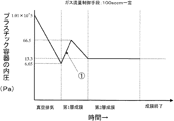
図1に示す高周波を外部電極に印加する高周波プラズマCVD法でDLC膜を成膜する。原料ガスとして高純度アセチレンを用いる。チャンバーとプラスチック容器の残存空気ガスを排気してプラスチック容器内の真空圧力を0.05Torr(6.65Pa)まで減圧した後、排気を継続しながら原料供給バルブ21を開いてプラスチック容器7内へ原料ガスを導入する。原料ガス流量は50sccmと一定とした。このとき、マスフローコントローラー23の背圧と配管22に滞留する原料ガス量に応じて決定される初期原料ガス流入量によって、プラスチック容器の内圧が一時的に設定成膜圧力0.10Torr(13.3Pa)よりも高くなり、最高0.4Torr(53.2Pa)程度まで上昇する。このときのプラスチック容器の容器内圧プロファイルを図3に示した。図3のプロファイルは前述した第1の実施形態の成膜方法に対応するものである。そして、図3の▲1▼に対応するタイミング、すなわち第1層成膜工程における第1のタイミングで高周波電力(13.56MHz)を500W供給し、プラズマCVDにより第1層の成膜を行った。圧力の変化に応じて第1層は傾斜組成の膜が形成される。第1層の成膜時間は0.3秒程度であり、設定成膜厚力0.10Torr(13.3Pa)到達後、そのまま第2層の成膜を行った。第2層の成膜時間は2.0秒程度とした。以上の成膜条件を表2に示した。第1層の厚みは4nm、第2層の厚みは20nmであり、これも合わせて表2に整理した。なお、第2層の成膜速度は凡そ10nm/秒であり、以下に示す実施例及び比較例では第2層の成膜時間を代えることで第2層の厚みを制御した。
【0073】
【表2】
(実施例2)
原料ガス流量を50sccmの一定から100sccmの一定に変更した以外は実施例1と同様に成膜を行ない、これを実施例2とした。容器内圧プロファイルは図4に示すものである。成膜条件と膜厚を表2に整理した。
【0075】
(実施例3)
高周波の印加のタイミングを図3の▲2▼とした以外は実施例1と同様に成膜を行ない、これを実施例3とした。前述の第1の実施形態の第1層成膜工程の第2のタイミングに相当する。成膜条件と膜厚を表2に整理した。
【0076】
(実施例4)
第2層成膜工程における高周波印加時間を実施例3(約1.3秒)よりも長くした(約2.0秒)以外は実施例3と同様に成膜を行ない、これを実施例4とした。成膜条件と膜厚を表2に整理した。
【0077】
(実施例5)
配管22の内部空間の体積を大きくして原料ガスの滞留体積を大きくした以外は実施例3と同様に成膜を行ない、これを実施例5とした。容器内圧プロファイルは図5に示す通りとなる。成膜条件と膜厚を表2に整理した。なお、配管22の内部空間の体積を大きくする代わりにマスフローコントローラーの背圧を高くすることでも同様の容器内圧プロファイルを得ることができる。
【0078】
(実施例6)
高周波の印加のタイミングを図3の▲3▼とした以外は実施例1と同様に成膜を行ない、これを実施例6とした。前述の第1の実施形態の第1層成膜工程の第2のタイミングに相当する。成膜条件と膜厚を表2に整理した。
【0079】
(実施例7)
図1に示す高周波を外部電極に印加する高周波プラズマCVD法でDLC膜を成膜する。原料ガスとして高純度アセチレンを用いる。チャンバーとプラスチック容器の残存空気ガスを排気してプラスチック容器内の真空圧力を0.05Torr(6.65Pa)まで減圧した後、排気を継続しながら原料供給バルブ21を開いてプラスチック容器7内へ原料ガスを導入する。原料ガス流量は100sccmとした。このときプラスチック容器の内圧が一時的に設定成膜圧力0.10Torr(13.3Pa)よりも高くなり、最高0.5Torr(66.5Pa)程度まで上昇する。このとき容器内部は原料ガスで充分置換される。その後原料ガス流量を50sccmに設定することで、容器の内圧を設定成膜圧力0.10Torr(13.3Pa)にする。このときのプラスチック容器の容器内圧プロファイルを図6に示した。図6のプロファイルは前述した第2の実施形態の成膜方法に対応するものである。そして、図6の▲3▼に対応するタイミングで高周波電力(13.56MHz)を500W供給し、プラズマCVDにより第1層の成膜を行った。圧力の変化に応じて第1層は傾斜組成の膜が形成される。第1層の成膜時間は0.3秒程度であり、設定成膜厚力到達後、そのまま第2層の成膜を行った。第2層の成膜時間は3.8秒程度とした。以上の成膜条件を表2に示した。第1層の厚みは3nm、第2層の厚みは38nmであり、これも合わせて表2に整理した。
【0080】
(実施例8)
実施例7における原料ガス流量100sccmを200sccmとしたこと以外は実施例7と同様に成膜を行ない、これを実施例8とした。すなわち、容器内圧を設定成膜圧力にする際の原料ガス流量50sccmは実施例7と同じである。また実施例8の容器内圧プロファイルは図7に示した。図7のプロファイルは前述した第2の実施形態の成膜方法に対応するものである。そして、図7の▲3▼に対応するタイミングで高周波電力(13.56MHz)を供給する。
【0081】
(実施例9)
図1に示す高周波を外部電極に印加する高周波プラズマCVD法でDLC膜を成膜する。原料ガスとして高純度アセチレンを用いる。チャンバーとプラスチック容器の残存空気ガスを排気してプラスチック容器内の真空圧力を0.05Torr(6.65Pa)まで減圧した後、排気を継続しながら原料供給バルブ21を開いてプラスチック容器7内へ原料ガスを導入する。原料ガス流量は50sccmとした。このとき、マスフローコントローラー23の背圧と配管22に滞留する原料ガス量に応じて決定される初期原料ガス流入量によって、プラスチック容器の内圧が一時的に設定成膜圧力0.10Torr(13.3Pa)よりも高くなり、最高0.4Torr(53.2Pa)程度まで上昇する。そして排気の継続により設定成膜圧力とする。この段階でプラスチック容器内はほぼ完全に原料ガスで置換される。その後原料ガスを75sccmに増やして一時的に設定成膜圧力よりも内圧を高くし、最高0.4Torr(53.2Pa)程度まで上昇させる。このときのプラスチック容器の容器内圧プロファイルを図8に示した。図8のプロファイルは前述した第3の実施形態の成膜方法に対応するものである。そして、図8の▲5▼に対応するタイミングで高周波電力(13.56MHz)を500W供給し、プラズマCVDにより第1層の成膜を行った。圧力の変化に応じて第1層は傾斜組成の膜が形成される。第1層の成膜時間は0.3秒程度であり、設定成膜厚力0.10Torr(13.3Pa)到達後、そのまま第2層の成膜を行った。第2層の成膜時間は1.3秒程度とした。以上の成膜条件を表2に示した。第1層の厚みは2nm、第2層の厚みは13nmであり、これも合わせて表2に整理した。
【0082】
(比較例1)
実施例1において高周波の印加タイミングを図3の0に対応するタイミングとした以外は実施例1と同様とし、これを比較例1とした。成膜条件、膜厚を表2に同様に示した。
【0083】
(比較例2)
実施例1において高周波の印加タイミングを図3の▲4▼に対応するタイミングとした以外は実施例1と同様とし、これを比較例2とした。成膜条件、膜厚を表2に同様に示した。
【0084】
(比較例3)
実施例8において高周波の印加タイミングを図7の▲2▼に対応するタイミングとした以外は実施例8と同様とし、これを比較例3とした。成膜条件、膜厚を表2に同様に示した。
【0085】
実施例1〜9及び比較例1〜3について、水素含量の測定を行った。PETボトル内面にSi基板を貼り付け、同一条件同一方法によりDLC膜をSi基板に200nm成膜した。RBS法(ラザフォード後方散乱分析法)−HFS法(水素前方散乱法)によるDLC膜の水素組成調査を行った。測定装置は、日新ハイボルテージ(株)製の後方散乱測定装置AN−2500を使用した。結果を表3に示した。
【0086】
実施例1〜9及び比較例1〜3について、ホット充填を考慮して、DLC膜を成膜後ホット充填時の容器の収縮を再現する加熱処理を行った。各実施例、各比較例のDLC膜コーティングプラスチック容器を90℃熱水下で10分間静置させ、さらに水で急冷し、乾燥後25℃の空気雰囲気下におく。加熱処理前後の酸素透過度、加熱処理後の付着強度を測定した。
【0087】
酸素透過度は、MOCON社製Oxtran2/20で測定した。23℃で外側湿度RH60%、内側湿度RH90%で行った。酸素透過度を表3に示した。
【0088】
加熱処理後の付着強度は、前記条件1による碁盤目テープ法、前記条件2による加重式引掻き法で測定した。碁盤目テープ法は切り傷によって100分割し、テープにより剥れなかった個数の割合として評価した。結果を表3に示した。
【0089】
ホット充填向け容器として、加熱処理後においても充分な密着強度を有し且つガスバリア性容器として十分なバリア性を有する場合を総合評価○とし、密着強度、ガスバリア性のいずれか若しくは両方が不充分である場合には総合評価×として表3に示した。
【0090】
【表3】
実施例1〜9では、DLC膜を水素原子含有率の異なる第1層と第2層とで構成したので加熱条件下にさらされた後でも密着性に優れ且つ第2層を主体とした容器のガスバリア性の確保ができていた。また、第1層を第2層につながるように傾斜組成としたので、応力集中等によるマイクロクラックの発生は生じなかった。
【0092】
それに対して比較例1では設定到達圧力に達した後直ぐに原料供給と放電を開始することから第1層の品質が容器ごとに不安定であった。比較例2では水素原子低含有組成のDLC膜のみの単一組成構造としたため硬質膜となり、加熱によるプラスチックの収縮条件下で充分な密着性を確保できなかった。比較例3では容器の内圧が0.8Torr(106Pa)と高いために内部電極の管内で放電が生じてしまい、容器内部でのプラズマが不安定で強度も弱く、膜厚が薄くなり酸素バリア性が充分でなかった。
【0093】
【発明の効果】
容器内表面に形成するDLC膜を水素原子高含有組成の第1層とその上に形成した第1層よりも相対的に水素原子低含有組成で少なくとも13nm以上の膜厚の第2層とから構成し、且つ第1層を第2層に対して傾斜組成とすることで、ホット充填を含むあらゆる充填方法に対応する容器が得られることを見出したことに伴い、本発明によりこの容器を複雑な装置を用いずに簡単な原料ガス制御により製造する方法を提供することができた。すなわち本発明にかかる製造方法により、第1層はプラスチック素材との密着性が高く、またプラスチックの収縮に追随し得る機能を有し且つ第2層は比較的硬質でガスバリア性の機能を有するものである。さらに第1層を第2層に対して容易に傾斜組成とすることができるので、第1層と第2層との境界における応力集中、マイクロクラックを防止することができる。
【0094】
特に本発明によれば、ブロー成形機などのプラスチック容器製造ライン等の他装置と同オーダーの量産速度(数百本/分程度)を低コストで信頼性高く実現することができる。
【0095】
また本発明は、容器の最適容器内圧プロファイルをいくつか提案するものであり、第1層の傾斜組成も複数形態提供することが可能であり、用途に応じて適宜選択することができる。いずれの製造方法も圧力制御に複雑な装置機構は必要とせず、排気量の制御も不要である。
【0096】
本発明において例えば第1の実施形態のように「ガス置換」と「傾斜膜成膜」の両方を同時に行なう場合には、ガス置換にかかる時間に傾斜膜の成膜も並行して行ない、時間短縮することができる。このガス置換は流量調節器と原料供給バルブの配置関係と動作の工夫により、たとえば1秒以下のきわめて短時間に行なうことができる。
【0097】
さらに本発明において例えば第2、第3の実施形態のように「ガス置換」と「傾斜膜成膜」の両方を分けてガス置換を完全に行なう場合には、DLC膜内に不純物の混入が少なく、再現性に優れるDLC膜コーティングプラスチック容器を製造することが可能である。
【図面の簡単な説明】
【図1】高周波プラズマCVD法によるDLC膜コーティングプラスチック容器の製造装置の概略図を示すものである。
【図2】本発明の実施例で使用するボトル形状の概略図であり、(a)は耐熱丸型、(b)は耐熱角型を示す。
【図3】第1の実施形態に対応する容器の容器内圧プロファイルの一形態を示す図である。
【図4】図3と比較して原料ガス流量を多くしたときの容器の容器内圧プロファイルの一形態を示す図である。
【図5】図3と比較して供給開始初期の原料ガス流入量を多くしたときの容器の容器内圧プロファイルの一形態を示す図である。
【図6】第2の実施形態に対応する容器の容器内圧プロファイルの一形態を示す図である。
【図7】図6と比較して原料ガス流量を多くしたときの容器の容器内圧プロファイルの一形態を示す図である。
【図8】第3の実施形態に対応する容器の容器内圧プロファイルの一形態を示す図である。
【符号の説明】
100,高周波プラズマCVD成膜装置
1,下部外部電極
2,上部外部電極
3,外部電極
4,絶縁部材
5,蓋部
6,チャンバー
7,PETボトル
8,Oリング
9,内部電極
9a,ガス吹きだし口
10,マッチングユニット
11,高周波電源
13,真空計
14,真空バルブ
16,真空ポンプ
17,ダクト排気
12,15,20,22,24,配管
21,原料供給バルブ
23,マスフローコントローラー
25,原料ガス発生源
26,原料ガス供給手段[0001]
TECHNICAL FIELD OF THE INVENTION
The present invention relates to a gas-barrier plastic container for filling beverages represented by fermented carbonated beverages such as carbonated beverages, fruit-containing carbonated beverages, beer, low-malt beer, and fruit juice beverages, and a method for producing the same. Particularly, the gas barrier property is realized by a DLC (diamond-like carbon) film coated on the inner surface of a plastic container.
[0002]
[Prior art]
The method of filling and sterilizing beverage containers varies greatly depending on the type of beverage. For example, a carbonated beverage is filled at a low temperature so that carbon dioxide gas does not escape, and sterilization for each container is not performed. Fruit drinks, tea, coffee, soups and the like are hot-filled, that is, filled at 85 to 90 ° C. Of these, tea, coffee and soup are often sold after being heated to about 60 ° C.
[0003]
It is well known that plastic containers, especially PET (polyethylene terephthalate resin) bottles, have been put into practical use as beverage containers for soft drinks, carbonated drinks, carbonated drinks with fruit juice, high juice drinks, tea, coffee, etc. Is filled by any one of the filling methods described above.
[0004]
By the way, PET bottles cannot be said to have a sufficient oxygen gas barrier property for all beverages because of easy oxidation of the contents. Therefore, a plasma CVD (Chemical Vapor Deposition) method is used to coat the inner surface of a plastic container with a DLC film to impart a gas barrier property, particularly as a carbonated beverage or high fruit juice beverage container, and to prevent sorption of aroma components. And a DLC film-coated plastic container are disclosed (for example, see
[0005]
[Patent Document 1]
JP-A-8-53117
[Patent Document 2]
JP-A-8-53116
[0006]
[Problems to be solved by the invention]
By the way, in a hot filling, if the plastic container is a PET bottle, the contents are filled at a temperature higher than the glass transition point of the resin. PET bottles are formed by blow molding, but shrink slightly when exposed to temperatures higher than the glass transition point (63-78 ° C.) of PET.
[0007]
In the DLC film-coated plastic containers disclosed in
[0008]
When the present inventors examined filling in a container, among the above-mentioned filling methods, in particular, a hot-filled case in which the plastic container is required to follow the expansion and contraction of the DLC film (the plastic shrinks due to heating) (Filling method), it was found that microcracks occurred in the DLC film.
[0009]
Accordingly, the present inventors have conducted extensive studies on whether the DLC film can be provided with gas barrier properties without generating microcracks in the DLC film even when performing any filling method including the above case. The first layer having a composition with a high atomic content and the second layer having a composition with a hydrogen atom content lower than that of the first layer formed thereon and having a thickness of at least 13 nm or more can be used as the first layer. The second layer has a gas barrier function and the first layer has a gradient composition with respect to the second layer so that the boundary between the first and second layers can be formed. It has been found that a plastic container coated with a DLC film which prevents stress concentration and microcracks in the above becomes a plastic container which can be used for any of the above-mentioned filling methods, particularly hot filling. That is, in this container, the first layer having a high content of hydrogen atoms has a high adhesion to a plastic material, is relatively flexible and follows the shrinkage of plastic, and has a composition having a relatively low content of hydrogen atoms than the first layer. The second layer having a thickness of at least 13 nm is relatively hard and exhibits gas barrier properties if it has a thickness of 13 nm or more. When the first layer has a gradient composition with respect to the second layer, microcracks do not occur.
[0010]
On the other hand, in order to make this technology practical to meet the needs of the market, mass production speed (about several hundred pieces / min) of the same order as other equipment such as a plastic container production line such as a blow molding machine should be used at low cost. Need to be implemented with high reliability. For this purpose, it is necessary to keep the total processing time of one layer within a few seconds, and the film formation time of the first layer needs to be as short as 1 second to several seconds or less.
[0011]
SUMMARY OF THE INVENTION An object of the present invention is to provide a method for manufacturing a plastic container coated with a DLC film having the above-mentioned two-layer structure capable of coping with hot filling in a simple manner in a short time. In other words, the content of hydrogen atoms in the film can be controlled by the level of the actual film formation pressure. If the film formation pressure is high, the DLC film has a high hydrogen atom composition, and if the film formation pressure is low, the DLC film has a low hydrogen atom content. Composition. Further, when starting supply of the source gas into the plastic container under the set ultimate pressure, the initial source gas flow rate is intentionally increased in order to promote gas replacement for improving the film quality of the barrier film. The supply of the initial gas increases the internal pressure of the container, and the internal pressure profile of the container is again reduced to the set film forming pressure by the balance between the exhaust gas and the supply amount of the source gas. By utilizing these, when the film forming pressure is high, the first layer is formed and when the film forming pressure reaches the set film forming pressure, the second layer is continuously formed, so that a DLC film coated plastic container having a two-layer structure can be easily formed. It is an object of the present invention to provide a manufacturing method. That is, by performing both the “gas replacement” and the “gradient film formation” simultaneously, the gradient film formation can be performed in parallel with the time required for the gas replacement, and the time can be reduced. This gas replacement can be performed in a very short time of, for example, 1 second or less, by arranging the flow relationship between the flow controller and the raw material supply valve and devising the operation. At this time, in the container internal pressure profile, there is a timing when the internal pressure is increasing, a timing when the internal pressure is the highest, or a timing when the internal pressure is reduced again. It is an object of the present invention to provide a method for easily manufacturing the same in a short time at low cost.
[0012]
Further, an object of the present invention is to supply a source gas by a gas system in which at least a source gas generating source, a gas flow rate control means, and a source supply valve enabling supply on / off are arranged in order, and to start supplying the source gas. By controlling the amount of increase in the internal pressure of the plastic container to be increased together with the supply of the initial gas by controlling at least one of the amount of the raw material gas remaining between the raw material supply valves and the back pressure of the gas flow control means from the gas flow control means, An object of the present invention is to provide a method of manufacturing a DLC film-coated plastic container with an optimized container internal pressure profile and containing less impurities.
[0013]
Further, it is an object of the present invention to sufficiently perform the replacement of the source gas, and after the replacement of the source material, supply the source gas to be supplied in the initial stage, and then control the amount of the source gas to be supplied so as to reduce the supply amount, thereby obtaining a desired container internal pressure. It is an object of the present invention to provide a method for manufacturing a DLC film-coated plastic container which realizes a profile, optimizes the container internal pressure profile, has almost no impurities, and has excellent reproducibility.
[0014]
A high-frequency output or a microwave output can be used as a plasma energy source. The object of the present invention is to select a high-frequency plasma energy and generate a self-bias voltage on the container wall surface, thereby providing a dense DLC having gas barrier properties. The purpose is to form a film.
[0015]
The function of the gas barrier property is to aim at securing the gas barrier property of about 5 times or more as compared with the uncoated container.
[0016]
[Means for Solving the Problems]
The means for solving the above problems are as follows. That is, in the method for manufacturing a DLC film-coated plastic container according to the present invention, a vacuum evacuation step of evacuating the inside of the plastic container to a set ultimate pressure is performed. A constant flow rate supply is started by the gas flow rate control means, the internal pressure of the plastic container is increased to a set film forming pressure or more, and the pressure is again reduced to the set film forming pressure with the continuation of the exhaust. A first layer forming step of supplying energy to convert the source gas inside the plastic container into plasma to form a DLC film having a high hydrogen atom content and a gradient composition as a first layer on the inner surface of the plastic container; Low hydrogen atom content on the first layer while maintaining the set film forming pressure while keeping the source gas in a plasma state. The second layer forming step of forming a DLC film having a constant composition as the second layer, characterized by having a city.
[0017]
In the method for producing a DLC film-coated plastic container according to the present invention, in the first layer film forming step, a constant output energy for plasma generation is supplied while increasing the internal pressure of the plastic container to a set film forming pressure or more. It is preferable to start plasma conversion of the source gas.
[0018]
Further, in the method for manufacturing a DLC film-coated plastic container according to the present invention, in the first layer forming step, the internal pressure of the plastic container is increased to a set film forming pressure or more, and the set film forming pressure is further increased with the continuation of evacuation. It is preferable to supply a constant output energy for plasma generation when the internal pressure becomes almost the maximum while the pressure is reduced again until the source gas is turned into plasma.
[0019]
Further, in the method for manufacturing a DLC film-coated plastic container according to the present invention, in the first layer film forming step, a plasma having a constant output is generated while the internal pressure of the plastic container is reduced again to the set film forming pressure with continuation of evacuation. It is preferable to supply energy for generation to start plasma of the raw material gas.
[0020]
Further, in the method for producing a DLC film-coated plastic container according to the present invention, the supply of the raw material gas to the inside of the plastic container is performed by controlling the flow rate of the raw material gas generated from a raw material gas generation source by gas flow rate control means, Further, the raw material gas whose flow rate is controlled by the gas flow rate control means is supplied by a gas system capable of being turned on and off by a raw material supply valve, and the amount of the raw material gas remaining between the raw material supply valves from the gas flow rate control means or It is preferable to control the amount of increase in the internal pressure of the plastic container, which is increased at the same time as the supply of the raw material gas, by adjusting the inflow amount of the raw material gas at the beginning of the supply by at least one of the back pressures of the gas flow control means. .
[0021]
Here, in the method for producing a DLC film-coated plastic container according to the present invention, it is preferable that the increase in the internal pressure of the plastic container is controlled with the increase due to the start of the supply of the raw material gas, and the exhaust gas amount is not adjusted. .
[0022]
The method for manufacturing a DLC film-coated plastic container according to the present invention includes a vacuum evacuation step of evacuating the interior of the plastic container to a set ultimate pressure, and a source gas containing a predetermined flow rate of a carbon source gas inside the plastic container while continuing the evacuation. To increase the internal pressure of the plastic container to a value equal to or higher than the set film forming pressure, and to set the gas flow rate smaller than the gas flow rate of the raw material gas in the gas replacement step in which the inside of the plastic container is gas-replaced. After that, with the continuation of the evacuation, a constant output energy for plasma generation is supplied while the pressure is reduced again to the set film forming pressure to convert the raw material gas inside the plastic container into plasma, thereby forming an inner surface of the plastic container. A first layer forming step of forming a DLC film having a high hydrogen atom content and a gradient composition as a first layer, A second layer forming step of forming a DLC film having a low hydrogen atom content and a constant composition as the second layer on the first layer while maintaining the set film forming pressure while keeping the raw material gas in a plasma state , And
[0023]
Further, the method for producing a DLC film-coated plastic container according to the present invention includes a vacuum evacuation step of evacuating the inside of the plastic container to a set ultimate pressure, wherein a raw material gas containing a carbon source gas is fixed inside the plastic container at a set film forming pressure. A gas replacement step of stabilizing the flow rate in a flowing state and replacing the inside of the plastic container with the raw material gas, and setting the gas flow rate larger than the gas flow rate of the raw material gas in the gas replacement step. After the elapse of a predetermined time after raising the internal pressure from the set film forming pressure, the gas flow rate of the raw material gas in the gas replacement step is set again, the internal pressure rise is stopped, and the pressure is reduced again to the set film forming pressure, and When the internal pressure rise is stopped, a constant output energy for plasma generation is supplied to the inside of the plastic container. A first layer forming step of forming the raw material gas into plasma and forming a DLC film having a high hydrogen atom content and a gradient composition as a first layer; and setting the set film forming pressure while maintaining the raw material gas in a plasma state. Forming a DLC film having a low hydrogen atom content and a constant composition as a second layer on the first layer while holding the second layer.
[0024]
Further, in the method for producing a DLC film-coated plastic container according to the present invention, after inserting an internal electrode from the mouth into the plastic container and disposing an external electrode outside the plastic container, high-frequency power is applied to the external electrode. It is preferable that the raw material gas is supplied and turned into plasma.
[0025]
BEST MODE FOR CARRYING OUT THE INVENTION
Hereinafter, the present invention will be described in detail with reference to embodiments and examples, but the present invention is not construed as being limited to these descriptions.
[0026]
In describing the method for manufacturing the DLC film-coated plastic container according to the present invention, one embodiment of a manufacturing apparatus that can use this manufacturing method will be described first. Since the manufacturing method of the present invention uses a plasma CVD method for converting a raw material gas into plasma, a high frequency or a microwave can be used as the energy source.
[0027]
One embodiment of an apparatus using a high-frequency plasma CVD method is shown in FIG. The high-frequency plasma CVD film forming apparatus 100 includes an external electrode 3, an internal electrode 9, a raw material
[0028]
The external electrode 3 forms a chamber 6 together with the conductive lid 5 and the insulating member 4. An insulating member 4 is arranged below the lid 5, and an external electrode 3 is arranged below the insulating member 4. The external electrode 3 includes an upper
[0029]
Although the CVD film forming apparatus 100 describes a film forming apparatus for a single plastic container, the chamber 6 and the internal electrodes 9 are arranged in parallel also when a DLC film is formed on the inner surfaces of a plurality of plastic containers at the same time. That can be applied.
[0030]
In this embodiment, the external electrode 3 is divided into the lower
[0031]
A space is formed inside the external electrode 3, and this space is for accommodating a plastic container to be coated, for example, a PET bottle 7 which is a container made of polyethylene terephthalate resin. The space inside the external electrode 3 is formed to be slightly larger than the outer shape of the PET bottle 7 housed therein. The insulating member 4 and the lid 5 are provided with openings that connect to spaces in the external electrodes. Further, a space is provided inside the lid portion 5, and this space is connected to the space inside the external electrode 3 via the opening. The space inside the external electrode 3 is sealed from the outside by an O-ring 8 arranged between the upper
[0032]
The impedance matching device (matching unit) 10 is connected to the lower
[0033]
The high-frequency power supply generates high-frequency power, which is energy for converting a raw material gas into plasma in a plastic container. The frequency of the high-frequency power supply is 100 kHz to 1000 MHz. For example, an industrial frequency of 13.56 MHz is used.
[0034]
The internal electrode 9 is arranged inside the external electrode 3 and inside the PET bottle 7. That is, the internal electrode 9 is inserted into the space inside the external electrode 3 from the upper portion of the lid 5 through the space in the lid 5 and the opening of the lid 5 and the insulating member 4. On the other hand, the
[0035]
The source gas supply means 26 introduces the source gas supplied from the source
[0036]
As the carbon source gas constituting the raw material gas, gaseous or liquid aliphatic hydrocarbons, aromatic hydrocarbons, oxygen-containing hydrocarbons, nitrogen-containing hydrocarbons, and the like at room temperature are used. For example, (1) methane CH4, Ethane C2H6, Propane C3H6, Butane C4H10, (2) ethylene C as ethylene-based2H4, Propylene C3H6, Butylene C4H8(3 isomers), (3) acetylene C as acetylene system2H2, Methyl acetylene C3H4, Ethyl acetylene (C4H6), (4) Others: normal hexane C6H14, Cyclohexane C6H12, (5) benzene C as an aromatic6H6, Toluene C6H5CH3, Xylene C6H4(CH3)2Can be exemplified. Particularly, benzene, toluene, o-xylene, m-xylene, p-xylene, cyclohexane and the like having 6 or more carbon atoms are desirable. However, when used in containers for foods and the like, aliphatic hydrocarbons, particularly methane-based hydrocarbons, ethylene-based hydrocarbons, and acetylene-based hydrocarbons are preferred from the viewpoint of hygiene. These carbon source gases may be used alone as a raw material gas, or may be used as a mixed gas of two or more kinds. Further, these gases may be diluted with a rare gas such as argon or helium for use. When forming a silicon-containing DLC film, a Si-containing hydrocarbon-based gas is used.
[0037]
The DLC film referred to in the present invention is a film called an i-carbon film or a hydrogenated amorphous carbon film (aC: H), and has a hydrogen content of 0 to 67% including a hard carbon film and polymer-like carbon. Carbon film. The DLC film is an amorphous carbon film, and SP3It also has a bond. A hydrocarbon-based gas, for example, an acetylene gas is used as a source gas for forming the DLC film, and a Si-containing hydrocarbon-based gas is used as a source gas for forming the Si-containing DLC film. By forming such a DLC film on the inner surface of a plastic container, a container which can be used as a one-way or returnable container for a carbonated beverage or a sparkling beverage is obtained.
[0038]
The space in the lid 5 is connected to one side of a pipe 12 in which a
[0039]
The resin used when molding the plastic container of the present invention is polyethylene terephthalate resin (PET), polyethylene terephthalate-based copolyester resin (a copolymer using cyclohexane dimethanol instead of ethylene glycol as the alcohol component of polyester is referred to as PETG). Eastman), polybutylene terephthalate resin, polyethylene naphthalate resin, polyethylene resin, polypropylene resin (PP), cycloolefin copolymer resin (COC, cyclic olefin copolymerization), ionomer resin, poly-4-methylpentene -1 resin, polymethyl methacrylate resin, polystyrene resin, ethylene-vinyl alcohol copolymer resin, acrylonitrile resin, polyvinyl chloride resin, polyvinylidene chloride resin, Polyamide resin, polyamideimide resin, polyacetal resin, polycarbonate resin, polysulfone resin, or ethylene tetrafluoride resin, acrylonitrile - styrene resins, acrylonitrile - butadiene - styrene resin, can be exemplified. Among them, PET is particularly preferred.
[0040]
Next, a method of forming a DLC film inside a container using the high-frequency plasma CVD film forming apparatus 100 shown in FIG. 1 will be described.
[0041]
(First Embodiment)
(PET bottle installation)
First, a vacuum valve (not shown) is opened to open the inside of the chamber 6 to the atmosphere. As a result, air enters the space in the lid 5 and the space in the external electrode 3, and the inside of the chamber 6 is brought to atmospheric pressure. Next, the lower
[0042]
(Evacuation process)
Then, after closing the vacuum valve (not shown), the
[0043]
(First layer deposition step)
Next, the raw
[0044]
In the first layer deposition process, the timing of starting the high frequency output is roughly classified into three types. First, as a first timing, a high-frequency output is started while the internal pressure of the PET bottle 7 is increased to a set film forming pressure or more. While the internal pressure rises and then returns to the set deposition pressure again, the hydrogen atom content of the first layer changes as follows. That is, the composition changes to a low hydrogen atom content composition, a high hydrogen atom content composition, and a low hydrogen atom content composition in the thickness direction of the film starting from the plastic surface. The first layer contains a composition containing a low amount of hydrogen atoms, but has a relatively high content of hydrogen atoms as compared with the second layer. Excellent adhesion to containers. Further, in addition to the gas-barrier property of the hydrogen-poor composition portion of the second layer, the hydrogen-poor composition portion of the first layer also exerts gas barrier property to a considerable extent. This method, in which the film formation time of the layer is the longest and the film thickness is large, has the highest gas barrier property.
[0045]
As a second timing, when the internal pressure of the PET bottle 7 is increased to the set film forming pressure or more and the pressure is reduced to the set film forming pressure again as the evacuation continues, the high frequency output starts when the internal pressure becomes almost the maximum. The way to do it. In this method, the hydrogen atom content of the first layer changes as follows. In other words, the composition changes from a high hydrogen atom content composition to a low hydrogen atom content composition in the thickness direction of the film starting from the plastic surface. Even when the composition of the second layer is taken into consideration, the composition of the DLC film as a whole starts from the surface of the plastic and gradually changes to a high hydrogen atom content composition and a low hydrogen atom content composition in the thickness direction of the film. For this reason, the first layer is a more flexible film and has a gradient composition because there is no composition containing a low content of hydrogen atoms immediately above the substrate as compared with the case of the first timing. Among them, it has the best adhesion to plastic containers.
[0046]
As a third timing, there is a method in which high-frequency output is started while the internal pressure of the PET bottle 7 is reduced again to the set film-forming pressure as the evacuation continues. In this method, the hydrogen atom content of the first layer changes as follows. In other words, the composition changes from a high hydrogen atom content composition to a low hydrogen atom content composition in the thickness direction of the film starting from the plastic surface. The state of the composition change is similar to that at the second timing, but the hydrogen atom content immediately above the inner surface of the plastic container is slightly lower than at the second timing. Adhesion is good next to the second timing. Discharge time can be shortened.
[0047]
The supply of the raw material gas to the inside of the PET bottle 7 is performed by controlling the flow rate of the raw material gas generated from the raw material
[0048]
In the initial stage of the supply of the source gas, it is preferable to perform the gas replacement promotion necessary for improving the film quality of the second-layer barrier film. preferable. Incidentally, the gases that require gas replacement are the atmosphere (oxygen and nitrogen) and the moisture adsorbed on the inner surface of the PET bottle 7.
[0049]
In this embodiment, the vacuum pump 16 is operated at a constant pumping speed, and the opening of the
[0050]
(Second layer deposition step)
A DLC film having a low hydrogen atom content and a constant composition is formed as a second layer on the first layer while maintaining a set film forming pressure while keeping the source gas in a plasma state. The first layer has a gradient composition according to the change in the film forming pressure, and the film forming pressure at the end of the first layer film forming step is the same as the film forming pressure at the start of the second layer film forming step. Therefore, no difference in composition and film stress occurs at the boundary between the first layer and the second layer. The thickness of the second layer can be 13 to 200 nm in consideration of stress, but is particularly preferably 13 to 38 nm in consideration of gas barrier properties and adhesion. If the thickness is less than 13 nm, the gas barrier properties are not sufficiently improved, and if the thickness exceeds 38 nm, microcracks may occur due to the internal stress of the film.
[0051]
The DLC film may be formed to have a thickness of, for example, 0.003 to 0.2 μm, but is preferably 15 to 40 nm from the viewpoint of gas barrier properties, productivity, residual stress in the film, and adhesion. .
[0052]
(Film formation completed)
Next, the RF output from the high-frequency power supply 11 is stopped, and the supply of the source gas is stopped by closing the
[0053]
(Second embodiment)
The installation of the PET bottle, the evacuation step, and the second layer deposition step are the same as in the first embodiment.
[0054]
(Gas replacement process)
Next, the raw
[0055]
(First layer deposition step)
After the gas replacement, the gas flow rate of the source gas in the gas replacement step is set to a gas flow rate smaller than the gas flow rate of the raw material gas, for example, 50 sccm in order to quickly return to the set film forming pressure, and then the film forming pressure is again increased to the set film forming pressure with the evacuation. During the pressure reduction, an RF output (for example, 13.56 MHz) is supplied to the external electrode 3 from the high frequency power supply (RF power supply) 11 via the
[0056]
(Third embodiment)
The installation of the PET bottle, the evacuation step, and the second layer deposition step are the same as in the first embodiment.
[0057]
(Gas replacement process)
The source
[0058]
(First layer deposition step)
In order to forcibly increase the internal pressure of the container, a gas flow rate larger than the gas flow rate of the raw material gas in the gas replacement step, for example, 100 sccm is set, and the internal pressure of the PET bottle 7 is raised above the set film forming pressure. After a lapse of a predetermined time, for example, 0.1 to 1 second, the gas flow rate of the source gas in the gas replacement step is set again to return to the set film forming pressure. As a result, the internal pressure of the plastic container stops increasing, and the pressure is reduced again to the set film forming pressure. When the internal pressure of the plastic container stops rising and reaches the maximum internal pressure, an RF output (for example, 13.56 MHz) is supplied to the external electrode 3 from the high frequency power supply (RF power supply) 11 via the
[0059]
In the present invention, the pressure during the plasma discharge is preferably set to 0.05 to 0.50 Torr (6.65 to 66.5 Pa). When the pressure is less than 0.05 Torr, the discharge is difficult, and when the pressure exceeds 0.60 Torr, a discharge occurs in the tube of the internal electrode, and the plasma discharge becomes unstable. It is preferable that the maximum pressure (the top pressure of the pressure increase) in the first layer film forming step is not less than the set film forming pressure and not more than 1.0 Torr (133 Pa). The reason for setting the pressure to 1.0 Torr or less is that it takes more time than necessary to return to the set film forming pressure. The pressure during the formation of the first layer is preferably higher than the pressure for forming the second layer and not more than 0.5 Torr (66.5 Pa). When the internal pressure is increased to a value equal to or higher than the set film forming pressure after the valve is opened in the first layer film forming step, the discharge impedance is set at the time of forming the second layer. ), The reflected power increases, and thus the power effectively entering the plasma decreases. For this reason, the ion energy incident on the film is reduced, the hydrogen content is large, the adhesion is high, and a flexible film is formed. The switch-on pressure at the time of plasma ignition is preferably 0.2 to 0.5 Torr (26.6 to 66.5 Pa). Similarly, it is for increasing the hydrogen atom content of the first layer within the discharge stable region pressure to obtain a flexible film quality. The pressure during the formation of the second layer (set film formation pressure) is preferably 0.05 to 0.2 Torr (6.65 to 26.6 Pa). This is because a gas barrier property is imparted by forming a hard film with a lower hydrogen atom content than the first layer. The present invention has found an optimum container internal pressure profile and its pressure range in order to form a DLC film having followability and gas barrier properties that can withstand bottle shrinkage during hot filling. Therefore, in the control of forming a film at a high internal pressure in the initial stage of film formation and thereafter providing a pressure difference of the internal pressure in which the film is formed at a low internal pressure, in order to obtain the bottle shrinkage following property and gas barrier property of the DLC film required by the present invention, Insufficient.
[0060]
In the first, second, and third embodiments, the exhaust pressure is fixed, and the internal pressure of the container is determined by the back pressure of the mass flow controller or the volume of the
[0061]
In the first, second, and third embodiments, in the present invention, not only a high-frequency power source but also a microwave power source may be used as means for converting the source gas into plasma. For example, 2.45 GHz is supplied as microwaves. Since microwaves are used as a plasma energy supply source, there are differences in the equipment used, such as supplying microwaves inside the container and eliminating the need for internal electrodes, but the manufacturing method is the same as when using a high-frequency power supply. is there.
[0062]
Furthermore, a DLC film may be formed by a magnetic field type plasma CVD method by installing a magnet near the outer wall of the container.
[0063]
In the embodiment, a PET bottle for a beverage is used as a container for forming a thin film inside, but a container used for other purposes can also be used.
[0064]
In the present invention, the number of components such as the number of film forming chambers and the number of high-frequency power sources may be appropriately changed depending on the required capacity of the apparatus.
[0065]
Next, a plastic container coated with a DLC film composed of a first layer and a second layer will be described. The DLC film-coated plastic container according to the present invention is obtained by coating the inner surface of a plastic container with a DLC film. Here, the DLC film is composed of a first layer having a high content of hydrogen atoms formed on the inner surface and a second layer having a relatively low content of hydrogen atoms than the first layer formed on the first layer. . The second layer preferably has a thickness of at least 13 nm or more. The hydrogen atom content of DLC can theoretically be 0 to 67 atomic%. At 67 atomic%, it is close to an ethylene polymer.
[0066]
According to the experience of the present inventors, a DLC film having a small hydrogen atom content is hard, has a large internal stress, and has a high gas barrier property. On the other hand, when the hydrogen atom content is large, the DLC film becomes relatively flexible, the internal stress is small, and the gas barrier property is low. The reason why the first layer is made to have a high content of hydrogen atoms in the present invention is to make the film flexible and to reduce the internal stress in the film, thereby making it possible to follow the shrinkage of the plastic and to enhance the adhesion of the film. Here, the high hydrogen atom content composition does not mean that it is close to 67 hydrogen atom%, but means that it is relatively high as compared with the hydrogen atom content rate of the second layer. On the other hand, the meaning of the low hydrogen atom content composition of the second layer also means that it is relatively low in comparison with the hydrogen atom content rate of the first layer. This is to ensure gas barrier properties, and it is preferable that the hydrogen atom content of the second layer be set to not less than 42 atomic% and not more than 48 atomic%. Therefore, as described above, the thickness of the second layer is particularly preferably 13 to 38 nm from the viewpoint of ensuring gas barrier properties. Further, the thickness of the first layer is preferably 2 to 6 nm from the viewpoint of adhesion and shortening of the film formation time. Here, the adhesiveness refers to the adhesiveness of the DLC film to shrinkage of the plastic due to heating after filling.
[0067]
The reason why the portion of the first layer that is in contact with the second layer has the graded composition is to reduce a difference in characteristics between the first layer and the second layer. In the present invention, a gradient composition can be easily obtained by controlling the film forming pressure.
[0068]
From the viewpoint of manufacturing a container that can be used irrespective of the method of filling the contents, a DLC film having different properties depending on the relationship between the first layer and the second layer is considered as follows, and a component for forming the DLC film is formed. Adjust the membrane pressure conditions as appropriate. That is, the DLC film-coated plastic container is allowed to stand at 90 ° C. in hot water for 10 minutes, rapidly cooled with water, dried, and then placed in an air atmosphere at 25 ° C. At this time, since the plastic is heated beyond the glass transition point, shrinkage of 1 to 2% occurs. The relationship between the first layer and the second layer is determined so that the DLC film placed under the condition of shrinkage of the plastic by heating is not peeled off by the grid tape method of JIS K5400 under
[0069]
The DLC film may be considered as follows. That is, the relationship between the first layer and the second layer is set such that the DLC film placed under the same plastic shrinkage condition by heating has a vertical load of 1.8 mN or more in the weighted scratching method under
[0070]
When the DLC film-coated plastic container according to the present invention is used as a container for hot filling, the first layer has a hydrogen atom content of 50 atomic% or more and 60 atomic% or less, and the second layer has a hydrogen atom content of 42 atomic% or less. It is preferable that the content be set to not less than atomic% and not more than 48 atomic%, preferably not less than 42 atomic% and not more than 46 atomic%. The reason why the hydrogen atom content of the first layer is set to 50 atomic% or more and 60 hydrogen atomic% or less is that internal stress is applied to the film due to shrinkage of the plastic, so that the internal stress does not remain in the film as much as possible when the first layer is formed. This is because it is better and the flexibility of the film can follow the shrinkage of the plastic.
[0071]
【Example】
The plastic container was a PET bottle. PET bottle height is 207mm, wall thickness is 0.3mm, container capacity is 500ml, inner surface area is 400cm2And The bottle (heat-resistant round type) shown in FIG. In the case of performing the heat treatment, a PET bottle (heat-resistant square type) shown in FIG. 2B can also be used. The PET bottles of the container (heat-resistant round type) in FIG. 2A and the container (heat-resistant square type) in FIG. 2B have a reduced-pressure absorbing surface or panel. Since the carbonic acid container has an internal pressure of carbon dioxide gas, it has a cylindrical conical shape. However, the heat-resistant container has a partly uneven portion on its body. In the case where the contents treated at a temperature of about 80 to 95 ° C. are filled in a container while maintaining the temperature and sealed and shipped as a product, when the contents are cooled to room temperature, the pressure in the container is reduced. A change in the shape of the container itself is inevitable. The wall surface of the body or the like having the uneven portion is referred to as a reduced pressure absorbing surface or panel. Table 1 summarizes the characteristics of each container shown in FIGS.
[Table 1]
(Example 1)
A DLC film is formed by a high frequency plasma CVD method in which a high frequency shown in FIG. 1 is applied to an external electrode. High-purity acetylene is used as a source gas. After the residual air gas in the chamber and the plastic container is evacuated to reduce the vacuum pressure in the plastic container to 0.05 Torr (6.65 Pa), the raw
[0073]
[Table 2]
(Example 2)
A film was formed in the same manner as in Example 1 except that the flow rate of the source gas was changed from a constant of 50 sccm to a constant of 100 sccm. The container internal pressure profile is shown in FIG. Table 2 shows the film forming conditions and film thicknesses.
[0075]
(Example 3)
A film was formed in the same manner as in Example 1 except that the timing of applying the high frequency was changed to (2) in FIG. This corresponds to the second timing of the first layer film forming step of the first embodiment. Table 2 shows the film forming conditions and film thicknesses.
[0076]
(Example 4)
A film was formed in the same manner as in Example 3 except that the high-frequency application time in the second layer film formation step was made longer (about 2.0 seconds) than in Example 3 (about 1.3 seconds). And Table 2 shows the film forming conditions and film thicknesses.
[0077]
(Example 5)
A film was formed in the same manner as in Example 3 except that the volume of the inner space of the
[0078]
(Example 6)
A film was formed in the same manner as in Example 1 except that the timing of applying the high frequency was changed to (3) in FIG. This corresponds to the second timing of the first layer film forming step of the first embodiment. Table 2 shows the film forming conditions and film thicknesses.
[0079]
(Example 7)
A DLC film is formed by a high frequency plasma CVD method in which a high frequency shown in FIG. 1 is applied to an external electrode. High-purity acetylene is used as a source gas. After exhausting the residual air gas in the chamber and the plastic container and reducing the vacuum pressure in the plastic container to 0.05 Torr (6.65 Pa), the raw
[0080]
(Example 8)
A film was formed in the same manner as in Example 7 except that the material gas flow rate in Example 7 was changed from 100 sccm to 200 sccm. That is, the raw material gas flow rate of 50 sccm when the container internal pressure is set to the set film forming pressure is the same as in the seventh embodiment. The internal pressure profile of the container of Example 8 is shown in FIG. The profile of FIG. 7 corresponds to the film forming method of the second embodiment described above. Then, high-frequency power (13.56 MHz) is supplied at a timing corresponding to (3) in FIG.
[0081]
(Example 9)
A DLC film is formed by a high frequency plasma CVD method in which a high frequency shown in FIG. 1 is applied to an external electrode. High-purity acetylene is used as a source gas. After the residual air gas in the chamber and the plastic container is exhausted to reduce the vacuum pressure in the plastic container to 0.05 Torr (6.65 Pa), the raw
[0082]
(Comparative Example 1)
Comparative Example 1 was the same as Example 1 except that the application timing of the high frequency was changed to the timing corresponding to 0 in FIG. Table 2 similarly shows film forming conditions and film thicknesses.
[0083]
(Comparative Example 2)
Comparative Example 2 was the same as Example 1 except that the application timing of the high frequency in Example 1 was changed to the timing corresponding to (4) in FIG. Table 2 similarly shows film forming conditions and film thicknesses.
[0084]
(Comparative Example 3)
Example 8 was the same as Example 8 except that the application timing of the high frequency was changed to the timing corresponding to (2) in FIG. Table 2 similarly shows film forming conditions and film thicknesses.
[0085]
For Examples 1 to 9 and Comparative Examples 1 to 3, the hydrogen content was measured. A Si substrate was attached to the inner surface of the PET bottle, and a DLC film was formed to a thickness of 200 nm on the Si substrate by the same method under the same conditions. The hydrogen composition of the DLC film was investigated by the RBS method (Rutherford backscattering analysis method) -HFS method (hydrogen forward scattering method). As a measuring device, a backscattering measuring device AN-2500 manufactured by Nisshin High Voltage Co., Ltd. was used. The results are shown in Table 3.
[0086]
In Examples 1 to 9 and Comparative Examples 1 to 3, heat treatment was performed to reproduce the shrinkage of the container during hot filling after forming the DLC film in consideration of hot filling. The DLC film-coated plastic containers of the respective Examples and Comparative Examples were allowed to stand at 90 ° C. in hot water for 10 minutes, rapidly cooled with water, dried, and then placed in an air atmosphere at 25 ° C. The oxygen permeability before and after the heat treatment and the adhesion strength after the heat treatment were measured.
[0087]
The oxygen permeability was measured with
[0088]
The adhesive strength after the heat treatment was measured by a cross-cut tape method under the
[0089]
When the container for hot filling has sufficient adhesion strength even after the heat treatment and has sufficient barrier properties as a gas barrier container, the overall evaluation is ○, and either or both of the adhesion strength and gas barrier properties are insufficient. In some cases, the results are shown in Table 3 as overall evaluations x.
[0090]
[Table 3]
In Examples 1 to 9, since the DLC film was composed of the first layer and the second layer having different hydrogen atom contents, the container having excellent adhesion even after being exposed under the heating condition and having the second layer as a main component was used. Gas barrier properties of Further, since the first layer was formed to have a gradient composition so as to be connected to the second layer, no microcracks occurred due to stress concentration or the like.
[0092]
On the other hand, in Comparative Example 1, the supply of the raw material and the discharge were started immediately after reaching the set ultimate pressure, so that the quality of the first layer was unstable for each container. In Comparative Example 2, a hard film was formed because only the DLC film having a composition containing a low amount of hydrogen atoms had a single composition structure, and sufficient adhesion could not be secured under the conditions of shrinkage of the plastic due to heating. In Comparative Example 3, since the internal pressure of the container was as high as 0.8 Torr (106 Pa), discharge occurred in the tube of the internal electrode, and the plasma inside the container was unstable and weak, the film thickness was reduced, and the oxygen barrier property was reduced. Was not enough.
[0093]
【The invention's effect】
The DLC film formed on the inner surface of the container is composed of a first layer having a high content of hydrogen atoms and a second layer having a composition having a relatively low content of hydrogen atoms and a thickness of at least 13 nm or more than the first layer formed thereon. According to the present invention, it has been found that a container corresponding to any filling method including hot filling can be obtained by constituting and having a gradient composition of the first layer with respect to the second layer. Thus, a method for manufacturing by simple raw material gas control without using a simple apparatus could be provided. That is, by the manufacturing method according to the present invention, the first layer has a high adhesion to the plastic material, has a function capable of following shrinkage of the plastic, and the second layer has a relatively hard and gas barrier function. It is. Furthermore, since the first layer can be easily made to have a gradient composition with respect to the second layer, stress concentration and microcracks at the boundary between the first layer and the second layer can be prevented.
[0094]
In particular, according to the present invention, a mass production speed (about several hundred pieces / minute) of the same order as that of another apparatus such as a plastic container production line such as a blow molding machine can be realized with low cost and high reliability.
[0095]
Further, the present invention proposes some optimum container internal pressure profiles of the container, and it is possible to provide a plurality of forms of the gradient composition of the first layer, which can be appropriately selected according to the application. Neither of the manufacturing methods requires a complicated apparatus mechanism for pressure control, and does not require control of the displacement.
[0096]
In the present invention, for example, when both “gas replacement” and “gradient film formation” are performed at the same time as in the first embodiment, the film formation of the gradient film is also performed in parallel with the time required for gas replacement. Can be shortened. This gas replacement can be performed in a very short time of, for example, 1 second or less, by arranging the flow relationship between the flow controller and the raw material supply valve and devising the operation.
[0097]
Further, in the present invention, when the gas replacement is completely performed by separating both the “gas replacement” and the “graded film formation” as in the second and third embodiments, for example, impurities are mixed in the DLC film. It is possible to manufacture a DLC film-coated plastic container which is small and excellent in reproducibility.
[Brief description of the drawings]
FIG. 1 is a schematic view of a manufacturing apparatus of a plastic container coated with a DLC film by a high-frequency plasma CVD method.
FIG. 2 is a schematic view of a bottle shape used in an embodiment of the present invention, in which (a) shows a heat-resistant round type, and (b) shows a heat-resistant square type.
FIG. 3 is a view showing one embodiment of a container internal pressure profile of the container corresponding to the first embodiment.
FIG. 4 is a view showing one form of a container internal pressure profile of the container when the flow rate of the source gas is increased as compared with FIG.
FIG. 5 is a view showing one form of a container internal pressure profile when the amount of raw material gas flowing in the initial stage of supply is increased as compared with FIG. 3;
FIG. 6 is a view showing one form of a container internal pressure profile of a container corresponding to the second embodiment.
7 is a view showing one form of a container internal pressure profile of the container when the flow rate of the source gas is increased as compared with FIG.
FIG. 8 is a view showing one form of a container internal pressure profile of a container corresponding to the third embodiment.
[Explanation of symbols]
100, high frequency plasma CVD film forming equipment
1, lower external electrode
2, Upper external electrode
3, external electrode
4, insulation member
5, lid
6, chamber
7, PET bottle
8, O-ring
9. Internal electrode
9a, gas outlet
10. Matching unit
11. High frequency power supply
13. Vacuum gauge
14. Vacuum valve
16. Vacuum pump
17, duct exhaust
12, 15, 20, 22, 24, piping
21, Raw material supply valve
23 、 Mass flow controller
25, source gas source
26, source gas supply means
Claims (9)
Priority Applications (1)
| Application Number | Priority Date | Filing Date | Title |
|---|---|---|---|
| JP2002336026A JP3970169B2 (en) | 2002-11-20 | 2002-11-20 | DLC film coated plastic container manufacturing method |
Applications Claiming Priority (1)
| Application Number | Priority Date | Filing Date | Title |
|---|---|---|---|
| JP2002336026A JP3970169B2 (en) | 2002-11-20 | 2002-11-20 | DLC film coated plastic container manufacturing method |
Publications (2)
| Publication Number | Publication Date |
|---|---|
| JP2004168359A true JP2004168359A (en) | 2004-06-17 |
| JP3970169B2 JP3970169B2 (en) | 2007-09-05 |
Family
ID=32699978
Family Applications (1)
| Application Number | Title | Priority Date | Filing Date |
|---|---|---|---|
| JP2002336026A Expired - Lifetime JP3970169B2 (en) | 2002-11-20 | 2002-11-20 | DLC film coated plastic container manufacturing method |
Country Status (1)
| Country | Link |
|---|---|
| JP (1) | JP3970169B2 (en) |
Cited By (28)
| Publication number | Priority date | Publication date | Assignee | Title |
|---|---|---|---|---|
| JP2006057008A (en) * | 2004-08-20 | 2006-03-02 | Plasma Ion Assist Co Ltd | Sealant and method for producing the same |
| JP2006089073A (en) * | 2004-09-22 | 2006-04-06 | Hokkai Can Co Ltd | Inner surface coated plastic container and method of manufacturing |
| JP2008202107A (en) * | 2007-02-21 | 2008-09-04 | Hitachi Kokusai Electric Inc | Substrate processing equipment |
| JP2010049050A (en) * | 2008-08-22 | 2010-03-04 | Hitachi Chem Co Ltd | Transparent resin laminate and method of manufacturing the same |
| US7985188B2 (en) | 2009-05-13 | 2011-07-26 | Cv Holdings Llc | Vessel, coating, inspection and processing apparatus |
| US8512796B2 (en) | 2009-05-13 | 2013-08-20 | Si02 Medical Products, Inc. | Vessel inspection apparatus and methods |
| JP2015010280A (en) * | 2013-06-27 | 2015-01-19 | 深▲セン▼富泰宏精密工業有限公司 | Workpiece and manufacturing method thereof |
| JP2015105397A (en) * | 2013-11-29 | 2015-06-08 | 三井造船株式会社 | Film forming method, film forming device and film |
| US9272095B2 (en) | 2011-04-01 | 2016-03-01 | Sio2 Medical Products, Inc. | Vessels, contact surfaces, and coating and inspection apparatus and methods |
| JP2016511798A (en) * | 2013-02-21 | 2016-04-21 | エリコン サーフェス ソリューションズ アーゲー、 トリュープバッハ | DLC coating with introductory layer |
| US9458536B2 (en) | 2009-07-02 | 2016-10-04 | Sio2 Medical Products, Inc. | PECVD coating methods for capped syringes, cartridges and other articles |
| US9545360B2 (en) | 2009-05-13 | 2017-01-17 | Sio2 Medical Products, Inc. | Saccharide protective coating for pharmaceutical package |
| US9554968B2 (en) | 2013-03-11 | 2017-01-31 | Sio2 Medical Products, Inc. | Trilayer coated pharmaceutical packaging |
| US9662450B2 (en) | 2013-03-01 | 2017-05-30 | Sio2 Medical Products, Inc. | Plasma or CVD pre-treatment for lubricated pharmaceutical package, coating process and apparatus |
| US9664626B2 (en) | 2012-11-01 | 2017-05-30 | Sio2 Medical Products, Inc. | Coating inspection method |
| US9764093B2 (en) | 2012-11-30 | 2017-09-19 | Sio2 Medical Products, Inc. | Controlling the uniformity of PECVD deposition |
| US9863042B2 (en) | 2013-03-15 | 2018-01-09 | Sio2 Medical Products, Inc. | PECVD lubricity vessel coating, coating process and apparatus providing different power levels in two phases |
| US9878101B2 (en) | 2010-11-12 | 2018-01-30 | Sio2 Medical Products, Inc. | Cyclic olefin polymer vessels and vessel coating methods |
| US9903782B2 (en) | 2012-11-16 | 2018-02-27 | Sio2 Medical Products, Inc. | Method and apparatus for detecting rapid barrier coating integrity characteristics |
| US9937099B2 (en) | 2013-03-11 | 2018-04-10 | Sio2 Medical Products, Inc. | Trilayer coated pharmaceutical packaging with low oxygen transmission rate |
| US10189603B2 (en) | 2011-11-11 | 2019-01-29 | Sio2 Medical Products, Inc. | Passivation, pH protective or lubricity coating for pharmaceutical package, coating process and apparatus |
| US10201660B2 (en) | 2012-11-30 | 2019-02-12 | Sio2 Medical Products, Inc. | Controlling the uniformity of PECVD deposition on medical syringes, cartridges, and the like |
| US11066745B2 (en) | 2014-03-28 | 2021-07-20 | Sio2 Medical Products, Inc. | Antistatic coatings for plastic vessels |
| US11077233B2 (en) | 2015-08-18 | 2021-08-03 | Sio2 Medical Products, Inc. | Pharmaceutical and other packaging with low oxygen transmission rate |
| US11116695B2 (en) | 2011-11-11 | 2021-09-14 | Sio2 Medical Products, Inc. | Blood sample collection tube |
| US11624115B2 (en) | 2010-05-12 | 2023-04-11 | Sio2 Medical Products, Inc. | Syringe with PECVD lubrication |
| WO2024060291A1 (en) * | 2022-09-20 | 2024-03-28 | 湖南千山制药机械股份有限公司 | Plastic cup injection and plating integrated machine, and injection, plating, filling and sealing integrated machine |
| US12257371B2 (en) | 2012-07-03 | 2025-03-25 | Sio2 Medical Products, Llc | SiOx barrier for pharmaceutical package and coating process |
-
2002
- 2002-11-20 JP JP2002336026A patent/JP3970169B2/en not_active Expired - Lifetime
Cited By (46)
| Publication number | Priority date | Publication date | Assignee | Title |
|---|---|---|---|---|
| JP2006057008A (en) * | 2004-08-20 | 2006-03-02 | Plasma Ion Assist Co Ltd | Sealant and method for producing the same |
| JP2006089073A (en) * | 2004-09-22 | 2006-04-06 | Hokkai Can Co Ltd | Inner surface coated plastic container and method of manufacturing |
| JP2008202107A (en) * | 2007-02-21 | 2008-09-04 | Hitachi Kokusai Electric Inc | Substrate processing equipment |
| JP2010049050A (en) * | 2008-08-22 | 2010-03-04 | Hitachi Chem Co Ltd | Transparent resin laminate and method of manufacturing the same |
| US9545360B2 (en) | 2009-05-13 | 2017-01-17 | Sio2 Medical Products, Inc. | Saccharide protective coating for pharmaceutical package |
| US8512796B2 (en) | 2009-05-13 | 2013-08-20 | Si02 Medical Products, Inc. | Vessel inspection apparatus and methods |
| US8834954B2 (en) | 2009-05-13 | 2014-09-16 | Sio2 Medical Products, Inc. | Vessel inspection apparatus and methods |
| US7985188B2 (en) | 2009-05-13 | 2011-07-26 | Cv Holdings Llc | Vessel, coating, inspection and processing apparatus |
| US10537273B2 (en) | 2009-05-13 | 2020-01-21 | Sio2 Medical Products, Inc. | Syringe with PECVD lubricity layer |
| US9572526B2 (en) | 2009-05-13 | 2017-02-21 | Sio2 Medical Products, Inc. | Apparatus and method for transporting a vessel to and from a PECVD processing station |
| US10390744B2 (en) | 2009-05-13 | 2019-08-27 | Sio2 Medical Products, Inc. | Syringe with PECVD lubricity layer, apparatus and method for transporting a vessel to and from a PECVD processing station, and double wall plastic vessel |
| US9458536B2 (en) | 2009-07-02 | 2016-10-04 | Sio2 Medical Products, Inc. | PECVD coating methods for capped syringes, cartridges and other articles |
| US11624115B2 (en) | 2010-05-12 | 2023-04-11 | Sio2 Medical Products, Inc. | Syringe with PECVD lubrication |
| US11123491B2 (en) | 2010-11-12 | 2021-09-21 | Sio2 Medical Products, Inc. | Cyclic olefin polymer vessels and vessel coating methods |
| US9878101B2 (en) | 2010-11-12 | 2018-01-30 | Sio2 Medical Products, Inc. | Cyclic olefin polymer vessels and vessel coating methods |
| US9272095B2 (en) | 2011-04-01 | 2016-03-01 | Sio2 Medical Products, Inc. | Vessels, contact surfaces, and coating and inspection apparatus and methods |
| US11116695B2 (en) | 2011-11-11 | 2021-09-14 | Sio2 Medical Products, Inc. | Blood sample collection tube |
| US10577154B2 (en) | 2011-11-11 | 2020-03-03 | Sio2 Medical Products, Inc. | Passivation, pH protective or lubricity coating for pharmaceutical package, coating process and apparatus |
| US11884446B2 (en) | 2011-11-11 | 2024-01-30 | Sio2 Medical Products, Inc. | Passivation, pH protective or lubricity coating for pharmaceutical package, coating process and apparatus |
| US11724860B2 (en) | 2011-11-11 | 2023-08-15 | Sio2 Medical Products, Inc. | Passivation, pH protective or lubricity coating for pharmaceutical package, coating process and apparatus |
| US10189603B2 (en) | 2011-11-11 | 2019-01-29 | Sio2 Medical Products, Inc. | Passivation, pH protective or lubricity coating for pharmaceutical package, coating process and apparatus |
| US11148856B2 (en) | 2011-11-11 | 2021-10-19 | Sio2 Medical Products, Inc. | Passivation, pH protective or lubricity coating for pharmaceutical package, coating process and apparatus |
| US12257371B2 (en) | 2012-07-03 | 2025-03-25 | Sio2 Medical Products, Llc | SiOx barrier for pharmaceutical package and coating process |
| US9664626B2 (en) | 2012-11-01 | 2017-05-30 | Sio2 Medical Products, Inc. | Coating inspection method |
| US9903782B2 (en) | 2012-11-16 | 2018-02-27 | Sio2 Medical Products, Inc. | Method and apparatus for detecting rapid barrier coating integrity characteristics |
| US11406765B2 (en) | 2012-11-30 | 2022-08-09 | Sio2 Medical Products, Inc. | Controlling the uniformity of PECVD deposition |
| US9764093B2 (en) | 2012-11-30 | 2017-09-19 | Sio2 Medical Products, Inc. | Controlling the uniformity of PECVD deposition |
| US10363370B2 (en) | 2012-11-30 | 2019-07-30 | Sio2 Medical Products, Inc. | Controlling the uniformity of PECVD deposition |
| US10201660B2 (en) | 2012-11-30 | 2019-02-12 | Sio2 Medical Products, Inc. | Controlling the uniformity of PECVD deposition on medical syringes, cartridges, and the like |
| JP2016511798A (en) * | 2013-02-21 | 2016-04-21 | エリコン サーフェス ソリューションズ アーゲー、 トリュープバッハ | DLC coating with introductory layer |
| US9662450B2 (en) | 2013-03-01 | 2017-05-30 | Sio2 Medical Products, Inc. | Plasma or CVD pre-treatment for lubricated pharmaceutical package, coating process and apparatus |
| US10016338B2 (en) | 2013-03-11 | 2018-07-10 | Sio2 Medical Products, Inc. | Trilayer coated pharmaceutical packaging |
| US9554968B2 (en) | 2013-03-11 | 2017-01-31 | Sio2 Medical Products, Inc. | Trilayer coated pharmaceutical packaging |
| US12239606B2 (en) | 2013-03-11 | 2025-03-04 | Sio2 Medical Products, Llc | PECVD coated pharmaceutical packaging |
| US9937099B2 (en) | 2013-03-11 | 2018-04-10 | Sio2 Medical Products, Inc. | Trilayer coated pharmaceutical packaging with low oxygen transmission rate |
| US10912714B2 (en) | 2013-03-11 | 2021-02-09 | Sio2 Medical Products, Inc. | PECVD coated pharmaceutical packaging |
| US11298293B2 (en) | 2013-03-11 | 2022-04-12 | Sio2 Medical Products, Inc. | PECVD coated pharmaceutical packaging |
| US11344473B2 (en) | 2013-03-11 | 2022-05-31 | SiO2Medical Products, Inc. | Coated packaging |
| US10537494B2 (en) | 2013-03-11 | 2020-01-21 | Sio2 Medical Products, Inc. | Trilayer coated blood collection tube with low oxygen transmission rate |
| US11684546B2 (en) | 2013-03-11 | 2023-06-27 | Sio2 Medical Products, Inc. | PECVD coated pharmaceutical packaging |
| US9863042B2 (en) | 2013-03-15 | 2018-01-09 | Sio2 Medical Products, Inc. | PECVD lubricity vessel coating, coating process and apparatus providing different power levels in two phases |
| JP2015010280A (en) * | 2013-06-27 | 2015-01-19 | 深▲セン▼富泰宏精密工業有限公司 | Workpiece and manufacturing method thereof |
| JP2015105397A (en) * | 2013-11-29 | 2015-06-08 | 三井造船株式会社 | Film forming method, film forming device and film |
| US11066745B2 (en) | 2014-03-28 | 2021-07-20 | Sio2 Medical Products, Inc. | Antistatic coatings for plastic vessels |
| US11077233B2 (en) | 2015-08-18 | 2021-08-03 | Sio2 Medical Products, Inc. | Pharmaceutical and other packaging with low oxygen transmission rate |
| WO2024060291A1 (en) * | 2022-09-20 | 2024-03-28 | 湖南千山制药机械股份有限公司 | Plastic cup injection and plating integrated machine, and injection, plating, filling and sealing integrated machine |
Also Published As
| Publication number | Publication date |
|---|---|
| JP3970169B2 (en) | 2007-09-05 |
Similar Documents
| Publication | Publication Date | Title |
|---|---|---|
| JP3970169B2 (en) | DLC film coated plastic container manufacturing method | |
| JP4437647B2 (en) | Method for producing gas container coated plastic container | |
| US20050229851A1 (en) | Plasma cvd film forming apparatus and method for manufacturing cvd film coated plastic container | |
| JP4252347B2 (en) | Method for producing gas barrier thin film coated plastic container | |
| WO2006126677A1 (en) | Apparatus for manufacturing gas barrier plastic container, method for manufacturing the container, and the container | |
| KR20110134398A (en) | Process for depositing diamond-like carbon as a protective coating on the inner surface of molded article | |
| TW200416138A (en) | Process and apparatus for depositing plasma coating onto a container | |
| EP1802686A1 (en) | Process for plasma coating | |
| JP2005200044A (en) | Plastic container and manufacturing method thereof | |
| JP4566719B2 (en) | Carbon film coated plastic container manufacturing method, plasma CVD film forming apparatus and plastic container | |
| WO2000071780A1 (en) | Dlc film, dlc-coated plastic container, and method and apparatus for manufacturing dlc-coated plastic container | |
| JP4372833B1 (en) | Method for producing gas barrier thin film coated plastic container | |
| JP4664658B2 (en) | Plasma CVD film forming apparatus and method for manufacturing plastic container having gas barrier property | |
| JP3993971B2 (en) | Plastic container having gas barrier coating layer and method for producing the same | |
| JP2008544011A (en) | Polymer product having a thin film coating formed by plasma on at least one of its sides and a method for producing such a product | |
| JP2003236976A (en) | Silicon oxide coating film with excellent gas barrier property and packaging body using it | |
| JP4002164B2 (en) | DLC film-coated plastic container and manufacturing method thereof | |
| JP5273760B2 (en) | Plastic container | |
| JP4877934B2 (en) | Preform for gas barrier plastic container and method for producing gas barrier plastic container | |
| JP5610345B2 (en) | Manufacturing method of plastic container having gas barrier property, adapter for small container and thin film deposition apparatus | |
| JP2005105294A (en) | CVD film forming apparatus and CVD film coated plastic container manufacturing method | |
| JP4279127B2 (en) | Gas barrier thin film coated plastic container manufacturing apparatus and manufacturing method thereof | |
| WO2005035826A1 (en) | Plasma cvd film-forming apparatus | |
| AU2005334309B8 (en) | Apparatus for forming a coating film on an inner surface of a container | |
| JP2005200043A (en) | Plastic container |
Legal Events
| Date | Code | Title | Description |
|---|---|---|---|
| A521 | Request for written amendment filed |
Free format text: JAPANESE INTERMEDIATE CODE: A821 Effective date: 20050805 |
|
| A711 | Notification of change in applicant |
Free format text: JAPANESE INTERMEDIATE CODE: A711 Effective date: 20050805 |
|
| A621 | Written request for application examination |
Free format text: JAPANESE INTERMEDIATE CODE: A621 Effective date: 20050819 |
|
| A521 | Request for written amendment filed |
Free format text: JAPANESE INTERMEDIATE CODE: A821 Effective date: 20050808 |
|
| A711 | Notification of change in applicant |
Free format text: JAPANESE INTERMEDIATE CODE: A712 Effective date: 20060313 |
|
| A977 | Report on retrieval |
Free format text: JAPANESE INTERMEDIATE CODE: A971007 Effective date: 20070523 |
|
| TRDD | Decision of grant or rejection written | ||
| A01 | Written decision to grant a patent or to grant a registration (utility model) |
Free format text: JAPANESE INTERMEDIATE CODE: A01 Effective date: 20070531 |
|
| A61 | First payment of annual fees (during grant procedure) |
Free format text: JAPANESE INTERMEDIATE CODE: A61 Effective date: 20070605 |
|
| R150 | Certificate of patent or registration of utility model |
Free format text: JAPANESE INTERMEDIATE CODE: R150 Ref document number: 3970169 Country of ref document: JP Free format text: JAPANESE INTERMEDIATE CODE: R150 |
|
| A711 | Notification of change in applicant |
Free format text: JAPANESE INTERMEDIATE CODE: A712 Effective date: 20070730 |
|
| FPAY | Renewal fee payment (event date is renewal date of database) |
Free format text: PAYMENT UNTIL: 20100615 Year of fee payment: 3 |
|
| S111 | Request for change of ownership or part of ownership |
Free format text: JAPANESE INTERMEDIATE CODE: R313115 |
|
| FPAY | Renewal fee payment (event date is renewal date of database) |
Free format text: PAYMENT UNTIL: 20100615 Year of fee payment: 3 |
|
| R360 | Written notification for declining of transfer of rights |
Free format text: JAPANESE INTERMEDIATE CODE: R360 |
|
| FPAY | Renewal fee payment (event date is renewal date of database) |
Free format text: PAYMENT UNTIL: 20100615 Year of fee payment: 3 |
|
| R360 | Written notification for declining of transfer of rights |
Free format text: JAPANESE INTERMEDIATE CODE: R360 |
|
| R371 | Transfer withdrawn |
Free format text: JAPANESE INTERMEDIATE CODE: R371 |
|
| FPAY | Renewal fee payment (event date is renewal date of database) |
Free format text: PAYMENT UNTIL: 20100615 Year of fee payment: 3 |
|
| S111 | Request for change of ownership or part of ownership |
Free format text: JAPANESE INTERMEDIATE CODE: R313115 |
|
| FPAY | Renewal fee payment (event date is renewal date of database) |
Free format text: PAYMENT UNTIL: 20100615 Year of fee payment: 3 |
|
| R350 | Written notification of registration of transfer |
Free format text: JAPANESE INTERMEDIATE CODE: R350 |
|
| A072 | Dismissal of procedure [no reply to invitation to correct request for examination] |
Free format text: JAPANESE INTERMEDIATE CODE: A072 Effective date: 20071214 |
|
| FPAY | Renewal fee payment (event date is renewal date of database) |
Free format text: PAYMENT UNTIL: 20100615 Year of fee payment: 3 |
|
| FPAY | Renewal fee payment (event date is renewal date of database) |
Free format text: PAYMENT UNTIL: 20110615 Year of fee payment: 4 |
|
| R250 | Receipt of annual fees |
Free format text: JAPANESE INTERMEDIATE CODE: R250 |
|
| FPAY | Renewal fee payment (event date is renewal date of database) |
Free format text: PAYMENT UNTIL: 20110615 Year of fee payment: 4 |
|
| FPAY | Renewal fee payment (event date is renewal date of database) |
Free format text: PAYMENT UNTIL: 20140615 Year of fee payment: 7 |
|
| R250 | Receipt of annual fees |
Free format text: JAPANESE INTERMEDIATE CODE: R250 |
|
| R250 | Receipt of annual fees |
Free format text: JAPANESE INTERMEDIATE CODE: R250 |
|
| S111 | Request for change of ownership or part of ownership |
Free format text: JAPANESE INTERMEDIATE CODE: R313115 |
|
| R350 | Written notification of registration of transfer |
Free format text: JAPANESE INTERMEDIATE CODE: R350 |
|
| R250 | Receipt of annual fees |
Free format text: JAPANESE INTERMEDIATE CODE: R250 |
|
| S531 | Written request for registration of change of domicile |
Free format text: JAPANESE INTERMEDIATE CODE: R313531 |
|
| S533 | Written request for registration of change of name |
Free format text: JAPANESE INTERMEDIATE CODE: R313533 |
|
| R350 | Written notification of registration of transfer |
Free format text: JAPANESE INTERMEDIATE CODE: R350 |
|
| R250 | Receipt of annual fees |
Free format text: JAPANESE INTERMEDIATE CODE: R250 |
|
| R250 | Receipt of annual fees |
Free format text: JAPANESE INTERMEDIATE CODE: R250 |
|
| R250 | Receipt of annual fees |
Free format text: JAPANESE INTERMEDIATE CODE: R250 |
|
| S531 | Written request for registration of change of domicile |
Free format text: JAPANESE INTERMEDIATE CODE: R313531 |
|
| R350 | Written notification of registration of transfer |
Free format text: JAPANESE INTERMEDIATE CODE: R350 |
|
| S111 | Request for change of ownership or part of ownership |
Free format text: JAPANESE INTERMEDIATE CODE: R313117 |
|
| R350 | Written notification of registration of transfer |
Free format text: JAPANESE INTERMEDIATE CODE: R350 |
|
| R250 | Receipt of annual fees |
Free format text: JAPANESE INTERMEDIATE CODE: R250 |
|
| EXPY | Cancellation because of completion of term |