JP2004161189A - In-wheel motor system - Google Patents
In-wheel motor system Download PDFInfo
- Publication number
- JP2004161189A JP2004161189A JP2002331604A JP2002331604A JP2004161189A JP 2004161189 A JP2004161189 A JP 2004161189A JP 2002331604 A JP2002331604 A JP 2002331604A JP 2002331604 A JP2002331604 A JP 2002331604A JP 2004161189 A JP2004161189 A JP 2004161189A
- Authority
- JP
- Japan
- Prior art keywords
- motor
- wheel
- rotor
- guide rail
- side guide
- Prior art date
- Legal status (The legal status is an assumption and is not a legal conclusion. Google has not performed a legal analysis and makes no representation as to the accuracy of the status listed.)
- Granted
Links
- 238000013016 damping Methods 0.000 claims description 3
- 230000008878 coupling Effects 0.000 abstract description 15
- 238000010168 coupling process Methods 0.000 abstract description 15
- 238000005859 coupling reaction Methods 0.000 abstract description 15
- 230000005540 biological transmission Effects 0.000 abstract description 8
- 230000003247 decreasing effect Effects 0.000 abstract 1
- 230000033001 locomotion Effects 0.000 description 14
- 238000010586 diagram Methods 0.000 description 8
- 239000000725 suspension Substances 0.000 description 6
- 230000035939 shock Effects 0.000 description 4
- 239000006096 absorbing agent Substances 0.000 description 3
- 229910000831 Steel Inorganic materials 0.000 description 2
- 238000006243 chemical reaction Methods 0.000 description 2
- 239000010959 steel Substances 0.000 description 2
- 230000000694 effects Effects 0.000 description 1
- 230000001105 regulatory effect Effects 0.000 description 1
- 239000013585 weight reducing agent Substances 0.000 description 1
Images


Landscapes
- Electric Propulsion And Braking For Vehicles (AREA)
- Arrangement Or Mounting Of Propulsion Units For Vehicles (AREA)
Abstract
Description
【0001】
【発明の属する技術分野】
本発明は、ダイレクトドライブホイールを駆動輪とする車輌において用いられるインホイールモータシステムに関するものである。
【0002】
【従来の技術】
近年、電気自動車などのモータによって駆動される車輌においてはモータを車輪に内蔵するインホイールモータシステムが採用されつつある。ところで、従来のインホイールモータでは、モータ部が車輌の足回りを構成する部品の一つであるアップライトまたはナックルと呼ばれる部品に接続するスピンドル軸に固定され、モータロータ及びホイールが回転可能な構造となっている(例えば、特許文献1〜3参照)。
一般に、足回りにバネ等のサスペンション機構を備えた車輌においては、ホイールやナックル、サスペンションアームといったバネ下に相当する部品の質量、いわゆるバネ下質量が大きい程、凹凸路を走行したときにタイヤ接地力の変動が増大し、ロードホールディング性が悪化することが知られている。
【0003】
一方、電気自動車などのモータによって駆動される車輌においては、スペース効率や駆動力の伝達効率の高さから、モータを車輪に内蔵するインホイールモータが採用されることがある。しかしながら、従来のインホイールモータは、上記のように、モータステータ部が車輌の足回り部品に接続するスピンドル軸に回転可能に固定されるため、上記のバネ下質量がインホイールモータの分だけ増加し、その結果、タイヤ接地力変動が増大し、ロードホールディング性が悪化してしまうといった問題点があった。
【0004】
そこで、上記のような問題を解決するため、図5に示すように、中空形状のインホイールモータ3のステータ3Sを支持する非回転側ケース3aとナックル5とを、車輌の上下方向に案内する直動ガイド部材11と、この直動ガイド部材11の稼動方向に伸縮するバネ部材とダンパーとから成るショックアブゾーバ12とを備えた緩衝機構10によって連結するとともに、上記モータ3のロータ3Rを支持する回転側ケース3bとホイール2とを駆動力伝達機構であるフレキシブルカップリング20により結合する構成のインホイールモータシステムが提案されている。これにより、上記モータ3を車輌の足回り部品であるナックル5に対して弾性支持するとともに、トルクをホイール2へ効率よく伝達させ、かつ、上下運動方向に拘束することができるので、車輌のタイヤ接地力の変動を低減して、車輌のロードホールディング性を向上させることが可能となる。
上記フレキシブルカップリング20は、図6(a)にも示すように、複数枚の中空円盤状のプレート21A〜21Cと、隣接する上記プレート21A,21B及びプレート21B,21C間を結合するとともに、上記隣接するプレート21A,21B及びプレート21B,21Cを互いに円盤のラジアル方向に案内する直動ガイド22A,22Bとを備えたもので、上記直動ガイド22A,22Bとしては、例えば、図6(b)に示すように、上記プレート21A〜21Cのラジアル方向に延長する凸部を有するガイドレール22pと、上記プレート21A〜21Cのラジアル方向に延長する凹部を有し、上記ガイドレール22pに係合するガイド部材22qと、上記ガイドレール22pとガイド部材22qとをより円滑にスライドさせるために、上記ガイドレール22pの凸部とガイド部材22qの凹部との間に配設された複数の鋼球22mとから構成される。
上記ガイドレール22p及びガイド部材22qは、上記隣接するプレート21A,21B及びプレート21B,21Cを互いに円盤のラジアル方向に案内するようにスライドするので、インホイールモータ3は上記直動ガイド22A,22Bの作動方向、すなわち、円盤のラジアル方向に沿っては動くことができるが、回転方向には動くことができないため、ホイール2に回転トルクを効率的に伝達することが可能となる(例えば、特許文献4参照)。
【0005】
また、駆動力伝達機構として、図7,図8に示すように、上記直動ガイド22A,22Bに代えて、中間の中空円盤状プレート(以下、中間プレートという)21Bの、モータ3側とホイール2側のそれぞれの周上に、90°間隔で、かつ、プレートの表,裏の同位置に、複数の直動ガイド23,24を配置したフレキシブルカップリング20Zを用いた構成も提案されている。上記フレキシブルカップリング20Zでは、ガイドレール23aとガイド部材23bとから構成される、モータ3側に配置された直動ガイド23の稼動方向を、各中空円盤状プレート21A〜21Cの径方向に対して45°方向とし、ガイドレール24aとガイド部材24bとから構成される、ホイール2側に配置された直動ガイド24の稼動方向を、上記直動ガイド24の稼動方向に対して直交する方向としている。
ところで、上記フレキシブルカップリング20では、中間プレート21Bの表裏の同位置に直動ガイドがないので、上記直動ガイド22A,22Bは中空円盤状プレート21A〜21Cの周方向に対してオフセットされ、周方向に圧縮荷重を受ける部分では座屈変形の危険がある。これに対して、上記フレキシブルカップリング20Zのような構成を採ることにより、インホイールモータ3からは、回転力のみがホイール2側のプレート21Cに伝達されるので、モータ3の駆動力をホイール2に確実に伝達させることができる。また、中間プレート21Bの周方向における荷重のオフセットをなくすことができるので、座屈の危険が減少する(例えば、特許文献4参照)。
【0006】
【特許文献1】
特許第2676025号公報(第2頁、第1図)
【特許文献2】
特表平9−506236号公報(第9−12頁、第1図)
【特許文献3】
特開平10−305735号公報(第3頁、第1図)
【特許文献4】
国際公開第02/83446号パンフレット
【0007】
【発明が解決しようとする課題】
しかしながら、上記構成のフレキシブルカップリング20Zでは、外乱があった場合、中間プレート21Bは偏心しながら回転するので、その振動によりモータ3が振動してしまうといった問題点があった。また、上記中間プレート21Bの偏心を見込んで、車輪内に所定のクリアランスを設ける必要があった。
更には、上記中間プレート21Bの表,裏の同位置にそれぞれ、直動ガイド23,24の一方の稼動方向を中間プレート21Bの径方向に対して45°方向とし、かつ、他方の稼動方向をそれに直交する方向に配置しなければならないため、組付けに高い精度が要求されるだけでなく、中間プレート21B上においても、それぞれの直動ガイド23と直動ガイド24間の角度もばらつきやすいといった問題点があった。
また、複数個の中空円盤状プレートが少なくとも3枚は必要であることから、駆動力伝達機構の重量が増加し、駆動系のイナーシャが大きくなってしまうという欠点がある。
【0008】
本発明は、従来の問題点に鑑みてなされたもので、組付けが容易で、かつ、モータへ伝達する振動を低減できるとともに、駆動系のイナーシャとを小さくすることのできる駆動力伝達機構を備えたインホイールモータシステムを提供することを目的とする。
【0009】
【課題を解決するための手段】
本発明の請求項1に記載の発明は、車輪部に設けられた中空形状のダイレクトドライブモータのステータ側が、車輌の足回り部品に対して、弾性体及び/または減衰機構を介して支持されたインホイールモータシステムであって、モータロータとホイールとを、ロータ周方向に等間隔に配置された、表裏で作動方向が直交する複数のクロスガイドにより連結したものである。これにより、表裏のガイド部材の作動方向を確実に規制することができるとともに、駆動伝達機構を軽量化できるので、駆動系のイナーシャを小さくすることが可能となる。また、軽量化により、モータに伝達する振動も低減できる。
また、請求項2に記載の発明は、請求項1に記載のインホイールモータシステムにおいて、上記クロスガイドのモータ側ガイドレールを、その稼動方向が全てモータロータの径方向に対して45°方向になるように配置するとともに、上記ホイール側ガイドレールの全ての稼動方向を上記モータ側ガイドレールの稼動方向に対して直交する方向になるように上記クロスガイドを配置したもので、これにより、座屈変形を確実に抑制することができ、回転力のみをホイール側に伝達することができる。
【0010】
【発明の実施の形態】
以下、本発明の実施の形態について、図面に基づき説明する。
図1は、本実施の形態に係わるインホイールモータシステムの構成を示す図で、同図において、1はタイヤ、2はリム2aとホイールディスク2bとから成るホイール、3は半径方向に対して内側に設けられた非回転側ケース3aに固定されたモータステータ(以下、ステータという)3Sと、半径方向に対して外側に設けられ、軸受け3jを介して上記非回転側ケース3aに対して回転可能に接合された回転側ケース3bに固定されたモータロータ(以下、ロータという)3Rとを備えたアウターロータ型のインホイールモータである。
4はホイール2とその回転軸において連結されたハブ部、5は上下のサスペンションアーム6a,6bに連結されるナックル、7はショックアブゾーバ等から成るサスペンション部材、8は上記ハブ部4に装着された制動装置、10は車輌の上下方向に案内する直動ガイド部材11と、この直動ガイド部材11の稼動方向に伸縮するバネ部材とダンパーとから成るショックアブゾーバ12とを備え、モータの非回転側ケース3aとナックル5とを連結する緩衝機構、30はモータの回転側ケース3bに取付けられた中空円盤状のモータ側プレート31と、ホイール2に取付けられた中空円盤状のホイール側プレート32と、上記プレート31,32間を結合する複数個のクロスガイド33とを備えたフレキシブルカップリングである。
【0011】
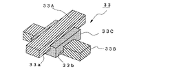
クロスガイド33は、図2に示すように、直交する2軸の直動ガイドを組合わせたもので、ビーム状の部材であるモータ側ガイドレール33Aとホイール側ガイドレール33Bと、直方体状の部材の上面及び下面にそれぞれ設けられた、上記ガイドレール33A,33Bをそれぞれ案内する案内溝33a,33bを備えたクロスガイド本体33Cとを備えている。これにより、モータ側ガイドレール33Aとホイール側ガイドレール33Bとは、クロスガイド本体33Cの案内溝33a,33bに沿って互いに直交する方向に稼動することができる。
本例では、図3に示すように、モータ側プレート31とホイール側プレート32との間に、上記クロスガイド33を4個等間隔(90°間隔)に配置するとともに、上記各クロスガイド33のモータ側ガイドレール33Aを、その稼動方向が全てロータ3Rの径方向に対して45°方向になるように配置している。したがって、各モータ側ガイドレール33Aの稼動方向は全て同方向(45°方向)を向き、各ホイール側ガイドレール33Bの全ての稼動方向は、上記各モータ側ガイドレール33Aの稼動方向に対してそれぞれ直交する方向となる。
【0012】
上記構成において、インホイールモータ3の回転側ケース3bからの回転力は、まず、モータ側プレート31を介して、モータ側ガイドレール33Aに入力される。このモータ側ガイドレール33Aに入力された周方向の力はクロスガイド本体33Cを通して、ホイール側ガイドレール33Bに伝達されホイール2を駆動する。
このとき、クロスガイド本体33Cには、図4に示すように、モータ側ガイドレール33Aからの入力とホイール側ガイドレール33Bからの反作用によって、周方向に回転する力と径方向外側に押し出される力とが作用する。
しかし、モータ側ガイドレール33Aとホイール側ガイドレール33Bとは回転する方向に動くが、常に互いに直交した方向を保とうとするため、上記クロスガイド33を径方向外側に押し出そうとする力は、クロスガイド本体33Cの捩れ反力と釣り合う。その結果、複数のクロスガイド33のみで偏心を吸収することができるので、ロータ3Rからのトルクをスムーズにホイール2に伝達させることができる。
【0013】
このように、本実施の形態によれば、緩衝機構10により、インホイールモータ3のステータ3Sを支持する非回転側ケース3aを、車輌上下方向に揺動可能に結合する構成のインホイールモータシステムにおいて、ロータ3Rを支持する回転側ケース3bとホイール2とを、モータ側ガイドレール33Aの稼動方向が全てロータ3Rの径方向に対して45°方向で、ホイール側ガイドレール33Bの全ての稼動方向が上記モータ側ガイドレール33Aの稼動方向に対して直交する方向となるように配置された複数個のクロスガイド33を備えたフレキシブルカップリング30で結合するようにしたので、モータ3の駆動力をホイール2に確実に伝達させることができる。
また、中間プレートを省略することができるので、フレキシブルカップリング30が軽量化され、モータ3へ伝達する振動を大幅に低減することができるとともに、駆動系のイナーシャを小さくすることができるだけでなく、車輪内に所定のクリアランスを設ける必要がないので、設計の自由度を上げることができる。更には、クロスガイド33を用いることにより、モータ側ガイドレール33Aとホイール側ガイドレール33Bとの作動方向を互いに直交する方向に限定することができるので、組付けが容易なだけでなく、フレキシブルカップリング30の動作を安定させることができる。
【0014】
なお、上記実施の形態では、4個のクロスガイド33を用いた場合について説明したが、クロスガイド33の個数はこれに限るものではなく、2個または3個、あるいは、5個以上であってもよい。このとき、上記各クロスガイド33は、モータ側プレート31とホイール側プレート32との間に、等間隔に配置することが好ましい。
また、クロスガイド33のガイドレール33A,33Bの形状は、図3に示すように、ビーム状に限定されるものではなく、クロスガイドの案内溝33a,33bに係合する凸部を有する部材であってもよい。また、上記ガイドレール33A,33Bをより円滑にスライドさせるために、上記案内溝33a,33bと上記ガイドレール33A,33Bの凸部との間に複数個の鋼球を配設するようにしてもよい。
【0015】
【発明の効果】
以上説明したように本発明によれば、中空形状のダイレクトドライブモータのステータ側が、車輌の足回り部品に対して、弾性体及び/または減衰機構を介して支持されたインホイールモータシステムにおいて、モータロータとホイールとを、ロータ周方向に等間隔に配置された、表裏で作動方向が直交する複数のクロスガイドにより連結するようにしたので、表裏のガイド部材の作動方向を確実に規制することができるとともに、駆動伝達機構を小型軽量化できるので、駆動系のイナーシャを小さくすることができる。また、軽量化により、モータに伝達する振動も大幅に低減することができる。
また、上記各クロスガイドのモータ側ガイドレールを、その稼動方向が全てモータロータの径方向に対して45°方向になるように配置するとともに、上記ホイール側ガイドレールの全ての稼動方向を上記モータ側ガイドレールの稼動方向に対して直交する方向に配置することにより、座屈変形を抑制することができ、回転力のみを確実にホイール側に伝達することができる。
また、本発明のインホイールモータシステムを採用することにより、スペース効率や駆動力の伝達効率に優れ、かつ、タイヤ接地力変動の少ないインホイールモータ車を実現することが可能となる。
【図面の簡単な説明】
【図1】本発明の実施の形態に係わるインホイールモータシステムの構成を示す縦断面図である。
【図2】本実施の形態に係わるクロスガイドの構成を示す図である。
【図3】本実施の形態に係わるフレキシブルカップリングの一構成例を示す図である。
【図4】フレキシブルカップリングの動作を説明するための図である。
【図5】従来のインホイールモータの構成を示す図である。
【図6】従来のフレキシブルカップリングの構成を示す図である。
【図7】従来のインホイールモータの他の構成を示す図である。
【図8】従来のフレキシブルカップリングの他の構成を示す図である。
【符号の説明】
1 タイヤ、2 ホイール、2a リム、2b ホイールディスク、
3 インホイールモータ、3R モータロータ、3S モータステータ、
3a 非回転側ケース、3b 回転側ケース、3j 軸受け、4 ハブ部、
5 ナックル、6a,6b サスペンションアーム、7 サスペンション部材、
8 制動装置、10 緩衝機構、11 直動ガイド部材、
12 ショックアブゾーバ、30 フレキシブルカップリング、
31 モータ側プレート、32 ホイール側プレート、33 クロスガイド、
33A モータ側ガイドレール、33B ホイール側ガイドレール、
33C クロスガイド本体。[0001]
TECHNICAL FIELD OF THE INVENTION
The present invention relates to an in-wheel motor system used in a vehicle having a direct drive wheel as a driving wheel.
[0002]
[Prior art]
2. Description of the Related Art In recent years, in vehicles driven by a motor such as an electric vehicle, an in-wheel motor system in which a motor is built in wheels has been adopted. By the way, in the conventional in-wheel motor, the motor portion is fixed to a spindle shaft connected to a component called an upright or a knuckle, which is one of components constituting the underbody of the vehicle, and has a structure in which the motor rotor and the wheel can rotate. (For example, see
Generally, in a vehicle equipped with a suspension mechanism such as a spring on the underbody, the larger the mass of the unsprung parts such as wheels, knuckles, and suspension arms, the larger the so-called unsprung mass, the more the tire touches the ground when traveling on an uneven road. It is known that the fluctuation of the force increases and the road holding performance deteriorates.
[0003]
On the other hand, in a vehicle driven by a motor such as an electric vehicle, an in-wheel motor in which a motor is built in a wheel may be adopted because of high space efficiency and high transmission efficiency of driving force. However, in the conventional in-wheel motor, as described above, the motor stator portion is rotatably fixed to the spindle shaft connected to the underbody part of the vehicle, so the unsprung mass increases by the amount of the in-wheel motor. However, as a result, there has been a problem that the variation in tire contact force is increased, and the road holding performance is deteriorated.
[0004]
Therefore, in order to solve the above problem, as shown in FIG. 5, the non-rotating side case 3a supporting the stator 3S of the hollow in-
As shown in FIG. 6A, the
The guide rail 22p and the guide member 22q slide so as to guide the adjacent plates 21A and 21B and the plates 21B and 21C in the radial direction of the disk, so that the in-
[0005]
As a driving force transmitting mechanism, as shown in FIGS. 7 and 8, instead of the
By the way, in the
[0006]
[Patent Document 1]
Japanese Patent No. 2676025 (
[Patent Document 2]
Japanese Unexamined Patent Publication No. 9-506236 (page 9-12, FIG. 1)
[Patent Document 3]
JP-A-10-305735 (
[Patent Document 4]
WO 02/83446 pamphlet [0007]
[Problems to be solved by the invention]
However, in the
Further, at the same position on the front and back of the intermediate plate 21B, one operating direction of the
Further, since at least three hollow disk-shaped plates are required, there is a disadvantage that the weight of the driving force transmission mechanism increases and the inertia of the driving system increases.
[0008]
The present invention has been made in view of the conventional problems, and provides a driving force transmission mechanism that is easy to assemble, can reduce vibration transmitted to a motor, and can reduce inertia of a driving system. It is an object to provide an in-wheel motor system provided with the same.
[0009]
[Means for Solving the Problems]
In the invention according to
According to a second aspect of the present invention, in the in-wheel motor system according to the first aspect, all the operating directions of the motor-side guide rails of the cross guide are 45 ° with respect to the radial direction of the motor rotor. And the cross guides are arranged so that all operating directions of the wheel-side guide rails are perpendicular to the operating direction of the motor-side guide rails. Can be reliably suppressed, and only the rotational force can be transmitted to the wheel side.
[0010]
BEST MODE FOR CARRYING OUT THE INVENTION
Hereinafter, embodiments of the present invention will be described with reference to the drawings.
FIG. 1 is a diagram showing a configuration of an in-wheel motor system according to the present embodiment, in which 1 is a tire, 2 is a wheel composed of a rim 2a and a
[0011]
As shown in FIG. 2, the
In this example, as shown in FIG. 3, four cross guides 33 are arranged at equal intervals (90 ° intervals) between the
[0012]
In the above configuration, the rotational force from the rotating case 3b of the in-
At this time, as shown in FIG. 4, the cross guide
However, although the motor-
[0013]
As described above, according to the present embodiment, the in-wheel motor system of the configuration in which the non-rotating side case 3a supporting the stator 3S of the in-
Further, since the intermediate plate can be omitted, the weight of the
[0014]
In the above-described embodiment, the case where four cross guides 33 are used has been described. However, the number of cross guides 33 is not limited to this, and is two or three, or five or more. Is also good. At this time, the cross guides 33 are preferably arranged at equal intervals between the motor-
Further, the shape of the
[0015]
【The invention's effect】
As described above, according to the present invention, in the in-wheel motor system in which the stator side of the hollow direct drive motor is supported via the elastic body and / or the damping mechanism with respect to the vehicle underbody parts, And the wheels are connected by a plurality of cross guides arranged at equal intervals in the circumferential direction of the rotor, and the operating directions are orthogonal on the front and back, so that the operating directions of the front and back guide members can be reliably restricted. At the same time, the drive transmission mechanism can be reduced in size and weight, so that the inertia of the drive system can be reduced. Further, the vibration transmitted to the motor can be significantly reduced due to the weight reduction.
In addition, the motor-side guide rails of each of the cross guides are arranged so that all the operating directions are at 45 ° to the radial direction of the motor rotor, and all the operating directions of the wheel-side guide rails are set to the motor side. By arranging the guide rails in a direction perpendicular to the operating direction, buckling deformation can be suppressed, and only rotational force can be reliably transmitted to the wheel side.
Further, by adopting the in-wheel motor system of the present invention, it is possible to realize an in-wheel motor vehicle that is excellent in space efficiency and transmission efficiency of driving force and that has little variation in tire contact force.
[Brief description of the drawings]
FIG. 1 is a longitudinal sectional view showing a configuration of an in-wheel motor system according to an embodiment of the present invention.
FIG. 2 is a diagram showing a configuration of a cross guide according to the present embodiment.
FIG. 3 is a diagram showing a configuration example of a flexible coupling according to the present embodiment.
FIG. 4 is a diagram for explaining the operation of the flexible coupling.
FIG. 5 is a diagram showing a configuration of a conventional in-wheel motor.
FIG. 6 is a diagram showing a configuration of a conventional flexible coupling.
FIG. 7 is a diagram showing another configuration of a conventional in-wheel motor.
FIG. 8 is a diagram showing another configuration of a conventional flexible coupling.
[Explanation of symbols]
1 tire, 2 wheels, 2a rim, 2b wheel disc,
3 in-wheel motor, 3R motor rotor, 3S motor stator,
3a non-rotating side case, 3b rotating side case, 3j bearing, 4 hub part,
5 knuckles, 6a, 6b suspension arms, 7 suspension members,
8 brake device, 10 buffer mechanism, 11 linear guide member,
12 shock absorbers, 30 flexible couplings,
31 Motor side plate, 32 Wheel side plate, 33 Cross guide,
33A motor side guide rail, 33B wheel side guide rail,
33C Cross guide body.
Claims (2)
Priority Applications (6)
| Application Number | Priority Date | Filing Date | Title |
|---|---|---|---|
| JP2002331604A JP4260462B2 (en) | 2002-11-15 | 2002-11-15 | In-wheel motor system |
| ES03791412T ES2380325T3 (en) | 2002-08-29 | 2003-08-29 | Motor system integrated in a wheel |
| CN03823417.3A CN1684851B (en) | 2002-08-29 | 2003-08-29 | In-wheel motor system |
| PCT/JP2003/011027 WO2004020236A1 (en) | 2002-08-29 | 2003-08-29 | In-wheel motor system |
| EP03791412A EP1547844B1 (en) | 2002-08-29 | 2003-08-29 | In-wheel motor system |
| US10/526,082 US7287611B2 (en) | 2002-08-29 | 2003-08-29 | In-wheel motor system |
Applications Claiming Priority (1)
| Application Number | Priority Date | Filing Date | Title |
|---|---|---|---|
| JP2002331604A JP4260462B2 (en) | 2002-11-15 | 2002-11-15 | In-wheel motor system |
Publications (2)
| Publication Number | Publication Date |
|---|---|
| JP2004161189A true JP2004161189A (en) | 2004-06-10 |
| JP4260462B2 JP4260462B2 (en) | 2009-04-30 |
Family
ID=32808923
Family Applications (1)
| Application Number | Title | Priority Date | Filing Date |
|---|---|---|---|
| JP2002331604A Expired - Fee Related JP4260462B2 (en) | 2002-08-29 | 2002-11-15 | In-wheel motor system |
Country Status (1)
| Country | Link |
|---|---|
| JP (1) | JP4260462B2 (en) |
Cited By (4)
| Publication number | Priority date | Publication date | Assignee | Title |
|---|---|---|---|---|
| WO2006030715A1 (en) * | 2004-09-14 | 2006-03-23 | Kabushiki Kaisha Bridgestone | Flexible coupling and in-wheel motor system |
| US7528518B2 (en) | 2005-01-19 | 2009-05-05 | Mitsubishi Jidosha Kogyo Kabushiki Kaisha | In-wheel motor |
| CN111114629A (en) * | 2019-12-30 | 2020-05-08 | 清华大学苏州汽车研究院(吴江) | Steering system and automobile |
| JP2021518298A (en) * | 2018-03-19 | 2021-08-02 | ディー.エス.レイダー エルティーディー | Wheel assembly |
-
2002
- 2002-11-15 JP JP2002331604A patent/JP4260462B2/en not_active Expired - Fee Related
Cited By (8)
| Publication number | Priority date | Publication date | Assignee | Title |
|---|---|---|---|---|
| WO2006030715A1 (en) * | 2004-09-14 | 2006-03-23 | Kabushiki Kaisha Bridgestone | Flexible coupling and in-wheel motor system |
| US7571784B2 (en) | 2004-09-14 | 2009-08-11 | Kabushiki Kaisha Bridgestone | Flexible coupling and in-wheel motor system |
| EP1808610A4 (en) * | 2004-09-14 | 2010-08-04 | Bridgestone Corp | Flexible coupling and in-wheel motor system |
| US7528518B2 (en) | 2005-01-19 | 2009-05-05 | Mitsubishi Jidosha Kogyo Kabushiki Kaisha | In-wheel motor |
| DE102006002421B4 (en) | 2005-01-19 | 2018-07-26 | Mitsubishi Jidosha Kogyo K.K. | wheel motor |
| JP2021518298A (en) * | 2018-03-19 | 2021-08-02 | ディー.エス.レイダー エルティーディー | Wheel assembly |
| CN111114629A (en) * | 2019-12-30 | 2020-05-08 | 清华大学苏州汽车研究院(吴江) | Steering system and automobile |
| CN111114629B (en) * | 2019-12-30 | 2025-03-14 | 清华大学苏州汽车研究院(吴江) | Steering system and automobile |
Also Published As
| Publication number | Publication date |
|---|---|
| JP4260462B2 (en) | 2009-04-30 |
Similar Documents
| Publication | Publication Date | Title |
|---|---|---|
| JP4133186B2 (en) | In-wheel motor system for steering wheels | |
| JP3638586B2 (en) | In-wheel motor mounting method and in-wheel motor system | |
| JP4113506B2 (en) | Wheel support device | |
| JP4287319B2 (en) | In-wheel motor system | |
| JP2005289324A (en) | Vehicle with rear wheel auxiliary drive motor | |
| WO2006030715A1 (en) | Flexible coupling and in-wheel motor system | |
| JP2004090793A (en) | In-wheel motor system | |
| JP4213028B2 (en) | In-wheel motor system | |
| JP4260462B2 (en) | In-wheel motor system | |
| JP5219718B2 (en) | In-wheel motor system | |
| JP4607603B2 (en) | Wheel support device | |
| JP4575298B2 (en) | In-wheel motor system | |
| JP4279067B2 (en) | In-wheel motor system | |
| JP4350591B2 (en) | In-wheel motor system | |
| JP4350442B2 (en) | In-wheel motor system | |
| JP2005329767A (en) | In-wheel motor system | |
| JP2005329911A (en) | In-wheel motor system | |
| JP2007168507A (en) | In-wheel motor system | |
| JP2005035323A (en) | In-wheel motor system | |
| JP2007161177A (en) | In-wheel motor system | |
| JP2005329905A (en) | In-wheel motor system |
Legal Events
| Date | Code | Title | Description |
|---|---|---|---|
| A621 | Written request for application examination |
Free format text: JAPANESE INTERMEDIATE CODE: A621 Effective date: 20051028 |
|
| A131 | Notification of reasons for refusal |
Free format text: JAPANESE INTERMEDIATE CODE: A131 Effective date: 20081104 |
|
| A521 | Written amendment |
Free format text: JAPANESE INTERMEDIATE CODE: A523 Effective date: 20081224 |
|
| TRDD | Decision of grant or rejection written | ||
| A01 | Written decision to grant a patent or to grant a registration (utility model) |
Free format text: JAPANESE INTERMEDIATE CODE: A01 Effective date: 20090203 |
|
| A01 | Written decision to grant a patent or to grant a registration (utility model) |
Free format text: JAPANESE INTERMEDIATE CODE: A01 |
|
| A61 | First payment of annual fees (during grant procedure) |
Free format text: JAPANESE INTERMEDIATE CODE: A61 Effective date: 20090204 |
|
| FPAY | Renewal fee payment (event date is renewal date of database) |
Free format text: PAYMENT UNTIL: 20120220 Year of fee payment: 3 |
|
| R150 | Certificate of patent or registration of utility model |
Free format text: JAPANESE INTERMEDIATE CODE: R150 |
|
| FPAY | Renewal fee payment (event date is renewal date of database) |
Free format text: PAYMENT UNTIL: 20120220 Year of fee payment: 3 |
|
| FPAY | Renewal fee payment (event date is renewal date of database) |
Free format text: PAYMENT UNTIL: 20130220 Year of fee payment: 4 |
|
| FPAY | Renewal fee payment (event date is renewal date of database) |
Free format text: PAYMENT UNTIL: 20140220 Year of fee payment: 5 |
|
| R250 | Receipt of annual fees |
Free format text: JAPANESE INTERMEDIATE CODE: R250 |
|
| R250 | Receipt of annual fees |
Free format text: JAPANESE INTERMEDIATE CODE: R250 |
|
| LAPS | Cancellation because of no payment of annual fees |