【0001】
【発明の属する技術分野】
本発明は、非水電解質およびこの非水電解質を用いた非水電解質二次電池に関する。
【0002】
【従来の技術】
イオン性化合物は、通常、プラスに帯電したカチオンとマイナスに帯電したアニオンとが、静電気的に引き合って結晶を構成している。このイオン性化合物は水をはじめとする種々の液体に溶解し、電気を流す液体、すなわち、電解質溶液を与える。
このイオン性化合物の中には、室温においても液体状態を保ち、極低温で固化しないものもあり、このような室温以下で液体状態を保つイオン性化合物は、特に室温溶融塩またはイオン性液体と呼ばれている。一般的に、イオン性液体を構成するカチオンとアニオンとは、その間の静電的相互作用が小さくなるように、どちらか一方または両方が、ある程度の大きさを有する分子イオンであるとともに、電荷もまた静電的相互作用を小さくする理由で1価である。
【0003】
上記イオン性液体を電池等の電解質へ応用する研究が精力的に進められているが、一般的に、イオン性液体は、吸湿性が高く、空気中での取り扱いが困難であるという欠点を有しており、その応用が十分になされているとは言えなかった。
このような状況下、1992年にWilkesらによって報告された1−エチル−3−メチルイミダゾリウムテトラフルオロボレートは、空気中でも取り扱うことのできる画期的なイオン性液体で、これをきっかけにして側鎖の異なる多数のアルキルイミダゾリウムカチオンと、種々のアニオンとを組み合わせたイオン性液体が多数合成されるようになった。
【0004】
このような背景から、イオン性液体を非水電解質二次電池の電解質として使用する試みが次第になされ始め、例えば、特許文献1(特開平11−260400号公報)では、常温溶融塩(イオン性液体)とカーボネート化合物からなる非水電解質を用いた非水電解質二次電池が報告されている。
しかしながら、この公報で用いられている常温溶融塩は、主としてイミダゾリウムイオン系のものであり、比較的凝固点が高いことから、電池の低温特性という点において、未だ不充分である。
また、カーボネートを加えて常温溶融塩の還元分解を抑える工夫はなされているものの、塩自体の電位窓がそれほど広くないため、電池の充放電時に塩が還元分解を受け易く、実用上十分な性能を備えているとは言い難い。
【0005】
【特許文献1】
特開平11−260400号公報
【0006】
【発明が解決しようとする課題】
本発明は、このような事情に鑑みなされたもので、イオン性液体を含み、低温特性および安定性に優れた二次電池を与える非水電解質、およびこの非水電解質を備えた非水電解質二次電池を提供することを目的とする。
【0007】
【課題を解決するための手段及び発明の実施の形態】
本発明者らは、上記目的を達成するために鋭意検討を重ねた結果、置換基としてアルコキシアルキル基を少なくとも1つ有する4級アンモニウム塩および4級ホスホニウム塩が、イオン性液体としての性状を有すること、およびこれらのイオン性液体が、低融点を有し、かつ、広い電位窓を有しているため、電池の充放電時に還元分解を受けにくく、非水電解質として優れていることを見いだし、本発明を完成した。
【0008】
すなわち、本発明は、
1. 下記一般式(1)で示され、融点が50℃以下のイオン性液体と、このイオン性液体より貴な電位で還元分解される化合物と、リチウム塩とを含んでなることを特徴とする非水電解質、
【化4】
〔式中、R1〜R4は互いに同一もしくは異種の炭素数1〜5のアルキル基、またはR′−O−(CH2)n−で表されるアルコキシアルキル基(R′はメチル基またはエチル基を示し、nは1〜4の整数である。)を示し、これらR1、R2、R3およびR4のいずれか2個の基が環を形成していても構わない。ただし、R1〜R4の内少なくとも1つは上記アルコキシアルキル基である。Xは窒素原子またはリン原子を示し、Yは一価のアニオンを示す。〕
2. 下記一般式(1)で示され、融点が50℃以下のイオン性液体と、作用極を炭素質材料または金属リチウムとしたときに、前記イオン性液体より貴な電位で還元分解される化合物と、リチウム塩とを含んでなることを特徴とする非水電解質。
【化5】
〔式中、R1〜R4は互いに同一もしくは異種の炭素数1〜5のアルキル基、またはR′−O−(CH2)n−で表されるアルコキシアルキル基(R′はメチル基またはエチル基を示し、nは1〜4の整数である。)を示し、これらR1、R2、R3およびR4のいずれか2個の基が環を形成していても構わない。ただし、R1〜R4の内少なくとも1つは上記アルコキシアルキル基である。Xは窒素原子またはリン原子を示し、Yは一価のアニオンを示す。〕
3. 前記化合物の含有量が、0.1〜60重量%であることを特徴とする1または2の非水電解質、
4. 前記化合物の含有量が、0.1〜30重量%であることを特徴とする3の非水電解質、
5. 前記化合物が、エチレンカーボネート、プロピレンカーボネート、ビニレンカーボネート、ジメチルカーボネート、エチルメチルカーボネート、およびジエチルカーボネートから選ばれる1種または2種以上であることを特徴とする1〜4のいずれかの非水電解質、
6. 前記イオン性液体の融点が、25℃以下であることを特徴とする1〜5のいずれかの非水電解質、
7. 前記Xが、窒素原子、R′がメチル基、nが2であることを特徴とする1〜6のいずれかの非水電解質、
8. 前記イオン性液体が、下記一般式(2)で示されることを特徴とする1〜6のいずれかの非水電解質、
【化6】
〔式中、R′はメチル基またはエチル基を示し、Xは窒素原子またはリン原子を示し、Yは一価のアニオンを示す。また、Meはメチル基を、Etはエチル基を意味する。〕
9. 前記Yが、BF4 −、PF6 −、(CF3SO2)2N−、CF3SO3 −、またはCF3CO2 −であることを特徴とする請求項1〜8のいずれか1項に記載の非水電解質、
10. 前記リチウム塩が、LiBF4、LiPF6、Li(CF3SO2)2N、LiCF3SO3またはLiCF3CO2であることを特徴とする1〜9のいずれかの非水電解質、
11. リチウム含有複合酸化物を含む正極と、リチウムイオンを吸蔵・放出する炭素質材料または金属リチウムを含む負極と、これら正負極間に介在させたセパレータと、非水電解質とを備えて構成された非水電解質二次電池であって、前記非水電解質が、1〜10のいずれかの非水電解質であることを特徴とする非水電解質二次電池、
12. 前記セパレータが、厚み20〜50μm、空孔率25〜85%の多孔性フィルムまたは多孔性シートであることを特徴とする11の非水電解質二次電池、
13. 前記多孔性フィルムまたは多孔性シートが、セルロースを主成分として含むことを特徴とする12の非水電解質二次電池
を提供する。
【0009】
以下、本発明について更に詳しく説明する。
本発明に係る非水電解質に用いられるイオン性液体は、下記一般式(1)で示され、融点が50℃以下のものである。
【0010】
【化7】
〔式中、R1〜R4は互いに同一もしくは異種の炭素数1〜5のアルキル基、
またはR′−O−(CH2)n−で表されるアルコキシアルキル基(R′はメチル基またはエチル基を示し、nは1〜4の整数である。)を示し、これらR1、R2、R3およびR4のいずれか2個の基が環を形成していても構わない。ただし、R1〜R4の内少なくとも1つは上記アルコキシアルキル基である。Xは窒素原子またはリン原子を示し、Yは一価のアニオンを示す。〕
【0011】
ここで、炭素数1〜5のアルキル基としては、メチル基、エチル基、プロピル基、2−プロピル基、ブチル基、ペンチル基等が挙げられるが、イオン性液体の物理的性状および電気化学的特性を考慮すると、R1〜R4の少なくとも1つはメチル基、エチル基またはプロピル基、特に、メチル基またはエチル基であることが好ましい、なお、これらのエチル基またはプロピル基がその他のアルキル基と環を形成していてもよい。
また、R′−O−(CH2)n−で表されるアルコキシアルキル基としては、メトキシまたはエトキシメチル基、メトキシまたはエトキシエチル基、メトキシまたはエトキシプロピル基、メトキシまたはエトキシブチル基が挙げられる。上記nは1〜4の整数であるが、イオン性液体の物理的性状および電気化学的特性を考慮すると、2〜4が好ましく、特に、n=2が好ましい。
【0012】
また、R1〜R4のいずれか2個の基が環を形成している化合物としては、Xに窒素原子を採用した場合には、アジリジン環、アゼチジン環、ピロリジン環、ピペリジン環等を有する4級アンモニウム塩、一方、Xにリン原子を採用した場合には、ペンタメチレンホスフィン(ホスホリナン)環等を有する4級ホスホニウム塩等が挙げられる。
【0013】
特に、置換基として、上記R′がメチル基であり、nが2のメトキシエチル基を少なくとも1つ有する4級アンモニウム塩が好適である。
また、置換基として、メチル基、2つのエチル基、およびアルコキシエチル基を有する下記一般式(2)で示される4級塩も好適に用いることができる。
【0014】
【化8】
〔式中、R′はメチル基またはエチル基を示し、Xは窒素原子またはリン原子を示し、Yは一価のアニオンを示す。また、Meはメチル基を、Etはエチル基を意味する。〕
【0015】
上記一価のアニオンYとしては、特に限定されるものではなく、BF4 −、PF6 −、AsF6 −、SbF6 −、AlCl4 −、HSO4 −、ClO4 −、CH3SO3 −、CF3SO3 −、CF3CO2 −、(CF3SO2)2N−、(C2F5SO2)2N−、(C3F7SO2)2N−、(C4F9SO2)2N−、(CF3SO2)(C2F5SO2)N−、(CF3SO2)(C3F7SO2)N−、(CF3SO2)(C4F9SO2)N−、(C2F5SO2)(C3F7SO2)N−、(C2F5SO2)(C4F9SO2)N−、Cl−、Br−、I−等のアニオンを用いることができるが、非水系有機溶媒中での解離度、安定性等を考慮すると、BF4 −、PF6 −、(CF3SO2)2N−、CF3SO3 −、CF3CO2 −を用いることが好ましい。
これらの中でも、特に、イオン性液体の粘度をより低くして取り扱い性を高めるという点から、(CF3SO2)2N−を用いることが好ましく、また、汎用性が高く、PF6 −よりも水の影響を受けにくく扱いやすいという点から、BF4 −を用いることが好ましい。
【0016】
本発明において、好適に用いられる4級アンモニウム塩および4級ホスホニウム塩の具体例としては、以下の化合物(3)〜(11)が挙げられる(Meはメチル基、Etはエチル基を示す)。
【0017】
【化9】
【0018】
上記4級アンモニウム塩の一般的な合成法は、次の通りである。まず、3級アミン類と、アルキルハライドまたはジアルキル硫酸等とを混合し、必要に応じて加熱を行うことで4級アンモニウムハライド塩とする。なお、アルコキシエチルハライド、アルコキシメチルハライド等の反応性の低い化合物を用いる場合、オートクレーブ等を用いて加圧下で反応させることが好適である。
上述のようにして得られた4級アンモニウムハライド塩を、水等の水性媒体中に溶解し、ホウフッ化水素酸や、テトラフルオロリン酸等の必要とするアニオン種を発生させる試薬と反応させてアニオン交換反応を行い、4級アンモニウム塩を得ることができる。
【0019】
具体例として、4級アンモニウムテトラフルオロボレートの合成法を挙げると、4級アンモニウムハライドを水に溶解させ、酸化銀を加えて塩交換を行い、4級アンモニウム水酸化物塩とした後、ホウフッ化水素酸と反応させて目的物を得ることができる。この方法は、4級アンモニウム水酸化物塩生成の際に、塩交換により生じるハロゲン化銀の除去が容易に行えるため、純度の高い4級アンモニウムテトラフルオロボレートを合成するのに有効である。
【0020】
また、4級ホスホニウム塩は、4級アンモニウム塩と同様、3級ホスフィン類と、アルキルハライドまたはジアルキル硫酸等とを混合し、必要に応じて加熱を行うことで、一般的に合成することができる。
また、陰イオンを種々に変化させた4級ホスホニウム塩を製造する場合には、4級アンモニウム塩同様、4級ホスホニウムハライド(塩化物、臭化物、ヨウ化物)を、水性媒体中に溶解し、必要とするアニオン種を発生させる試薬と反応させて、アニオン交換反応を行えばよい。
【0021】
上記イオン性液体の融点は、50℃以下であり、好ましくは25℃以下、特に好ましくは15℃以下である。ここで、融点が50℃を超えると、低温下において電解質中でイオン性液体が析出し、イオン電導率が低下する可能性が高くなる。上記イオン性液体の融点は低いほど好ましく、その下限値は特に限定されない。
なお、本発明のイオン性液体は、従来からよく用いられているイミダゾリウムイオンを有するイオン性液体と比較して低い融点を有しているから、該イオン性液体を含む非水電解質を非水電解質二次電池の電解質に用いることで、より低温特性に優れた二次電池を得ることができる。
さらに、上記イオン性液体は、従来公知のイミダゾリウムイオンを有するイオン性液体と比較して、その含有する水分率を低減させる、または低く抑えることが可能であるので、該イオン性液体を含む非水電解質を非水電解質二次電池の電解質に用いることで、より高い充放電性能を有し、かつ繰り返し充放電を行った際にも劣化しにくい二次電池を得ることができる。
【0022】
また、上記イオン性液体は、従来公知のイミダゾリウムイオンを有するイオン性液体と比較して、広い電位窓を有しているから、それ自体充放電時に還元分解を受けにくく、さらに、後に詳述するイオン性液体よりも貴な電位で還元分解される化合物を上記イオン性液体に添加して電解質を調製することで、イオン性液体の充放電に伴う還元分解をより効果的に抑制することができ、その結果、繰り返し充放電を行った際にも劣化しにくい、安定性の高い二次電池を得ることができる。
【0023】
本発明に係る非水電解質は、上述したイオン性液体と、このイオン性液体より貴な電位で還元分解される化合物と、リチウム塩とを含んでなるものである。
ここで、イオン性液体より貴な電位で還元分解される化合物は、二次電池の活物質上、特に負極活物質上で、充放電に伴う電気化学反応により、SEI(Solid Electrolyte Interphase)と呼ばれる被膜を形成するものであり、この際にイオン性液体よりも貴な電位で還元分解されるという特性を有する化合物であれば特に限定されるものではなく、例えば、環状もしくは鎖状炭酸エステル、鎖状カルボン酸エステル、環状もしくは鎖状エーテル、リン酸エステル、ラクトン化合物、ニトリル化合物、アミド化合物またはこれらの混合物等を用いることができる。
【0024】
また、上記還元分解される電位の測定方法としては、例えば、サイクリックボルタンメトリー測定装置を用い、作用極、対極として白金電極、参照極に銀/塩化銀電極を使用する系、作用極として炭素質材料または金属リチウム、対極として白金電極、参照極に銀/塩化銀電極を使用する系でサイクリックボルタンメトリー測定を行う方法、定電流定電圧電源を使用し、作用極として炭素質材料電極、対極に金属リチウム電極、必要に応じて金属リチウム電極等の参照極を使用する系で、充放電試験を行うことによって測定する方法を用いることができる。
【0025】
特に、前記イオン性液体より貴な電位で還元分解される化合物の還元電位を測定するときには、実際の非水電解質二次電池特に、リチウムイオン二次電池やリチウム二次電池に近い系である作用極として炭素質材料電極または金属リチウム電極、対極として白金電極、参照極に銀/塩化銀電極を使用する系でのサイクリックボルタンメトリー測定や、作用極として炭素質材料電極、対極に金属リチウム電極、必要に応じて金属リチウム電極等の参照極を使用する系での充放電試験を行うことによって還元電位を測定することが好ましい。
【0026】
環状炭酸エステルとしては、例えば、プロピレンカーボネート、エチレンカーボネート,ブチレンカーボネート等のアルキレンカーボネートまたはビニレンカーボネートなどが挙げられる。鎖状炭酸エステルとしては、例えば、ジメチルカーボネート,エチルメチルカーボネート,ジエチルカーボネート等のジアルキルカーボネートが挙げられる。鎖状カルボン酸エステルとしては、例えば、酢酸メチル,プロピオン酸メチルなどが挙げられる。環状または鎖状エーテルとしては、例えば、テトラヒドロフラン,1,3−ジオキソラン,1,2−ジメトキシエタンなどが挙げられる。リン酸エステルとしては、例えば、リン酸トリメチル,リン酸トリエチル,リン酸エチルジメチル,リン酸ジエチルメチル,リン酸トリプロピル,リン酸トリブチル,リン酸トリ(トリフルオロメチル),リン酸トリ(トリクロロメチル),リン酸トリ(トリフルオロエチル),リン酸トリ(トリパーフルオロエチル),2−エトキシ−1,3,2−ジオキサホスホラン−2−オン,2−トリフルオロエトキシ−1,3,2−ジオキサホスホラン−2−オン、2−メトキシエトキシ−1,3,2−ジオキサホスホラン−2−オンなどが挙げられる。ラクトン化合物としては、例えば、γ−ブチロラクトンなどが挙げられる。ニトリル化合物としては、例えば、アセトニトリルなどが挙げられる。アミド化合物としては、例えば、ジメチルホルムアミドなどが挙げられる。
【0027】
これらの各種化合物の中でも、環状炭酸エステル、鎖状炭酸エステル、リン酸エステル、またはこれらの混合物は、高い充放電特性および高出力特性等の電池性能を示すことから、好適に用いられ、特に、エチレンカーボネート、プロピレンカーボネート、ビニレンカーボネート、ジメチルカーボネート、エチルメチルカーボネート、およびジエチルカーボネートから選ばれる1種または2種以上が好適に用いられる。中でも、エチレンカーボネート、プロピレンカーボネート、ビニレンカーボネート等の環状炭酸エステルは、引火点および発火点が高く、さらに蒸気圧も低いため安全性という観点より好適に用いられる。
【0028】
特に、上記ビニレンカーボネートは、その他のカーボネート化合物と比較してより貴な電位で還元分解され、均一で薄いSEIを形成することから、より好適に用いることができる。すなわち、ビニレンカーボネートを用いることで、電位窓が比較的狭いイオン性液体を電解質として使用することが可能になるとともに、このようなイオン性液体を用いた場合でも、ビニレンカーボネートが還元分解されて均一で薄いSEIを形成することで、非水電解質二次電池のSEIによるインピーダンスの上昇を抑制することができるものである。
【0029】
上記非水電解質において、イオン性液体よりも貴な電位で還元分解される化合物の含有量は、非水電解質全体に対して、0.1〜60重量%であることが好ましく、特に、0.1〜30重量%、より好ましくは0.2〜20重量%、より一層好ましくは0.4〜15重量%である。
ここで、上記化合物の含有量が、0.1重量%未満であると、上述した電位窓の広いイオン性液体を用いたとしても、このイオン性液体の充放電時の還元分解を効率的に抑制し難くなる虞が高まり、結果として二次電池のサイクル寿命および安定性の向上を達成できなくなる虞がある。一方、含有量が60重量%を超えると、不燃性であるイオン性液体の非水電解質中に占める割合が低くなるため、二次電池の安全性が低下する虞がある。
【0030】
上記リチウム塩としては、非水電解質二次電池に用いられる公知の種々のリチウム塩を用いることができ、例えば、LiBF4、LiPF6、LiAsF6、LiClO4、Li(CF3SO2)2N、Li(CF3SO2)2N、Li(C2F5SO2)2N、Li(C3F7SO2)2N、Li(C4F9SO2)2N、Li(CF3SO2)(C2F5SO2)N、Li(CF3SO2)(C3F7SO2)N、Li(CF3SO2)(C4F9SO2)N、Li(C2F5SO2)(C3F7SO2)N、Li(C2F5SO2)(C4F9SO2)N、Li(CF3OCF2SO2)2N、LiCF3SO3、LiCF3CO2等が使用できるが、汎用性、イオン性液体への溶解度および解離度等を考慮すると、特に、LiBF4、LiPF6、Li(CF3SO2)2N、LiCF3SO3またはLiCF3CO2を用いることが好ましい。
【0031】
また、上記電解質中におけるリチウム塩の含有量は、特に限定されるものではないが、通常、0.05〜3mol/L、好ましくは0.1〜2mol/Lである。リチウム塩の濃度が低すぎると、電池のインピーダンスが高くなり、大電流での充放電ができなくなる虞があり、一方、高すぎると、液粘度が高くなり、電池の製造が困難になる虞がある。
【0032】
以上のような本発明の非水電解質によれば、従来公知のイミダゾリウムイオンを有するイオン性液体よりも広い電位窓を有するイオン性液体を用いるとともに、これよりも貴な電位で還元分解される化合物を含有しているから、イオン性液体が充放電時に還元分解を受けにくく、結果として、この電解質を用いた非水電解質二次電池のサイクル維持率および安定性を向上させることができる。
また、上記イオン性液体が、従来公知のイミダゾリウムイオンを有するイオン性液体よりも低融点を有しているから、より一層低温特性に優れた非水電解質を得ることができる。
【0033】
上述した本発明の非水電解質は、高分子化合物と混合し、高分子電解質として使用することも可能である。
ここで、高分子化合物としては、特に限定されるものではないが、例えば、(a)ヒドロキシアルキル多糖誘導体、(b)オキシアルキレン分岐型ポリビニルアルコール誘導体、(c)ポリグリシドール誘導体、(d)シアノ基置換一価炭化水素基含有ポリビニルアルコール誘導体、(e)熱可塑性ポリウレタン等を好適に用いることができる。
【0034】
上記(a)ヒドロキシアルキル多糖類誘導体としては、▲1▼セルロース、デンプン、プルランなどの天然に産出される多糖類にエチレンオキシドを反応させることによって得られるヒドロキシエチル多糖類、▲2▼上記多糖類にプロピレンオキシドを反応させることによって得られるヒドロキシプロピル多糖類、▲3▼上記多糖類にグリシドールまたは3−クロロ−1,2−プロパンジオールを反応させることによって得られるジヒドロキシプロピル多糖類等が挙げられ、これらヒドロキシアルキル多糖類の水酸基の一部または全部がエステル結合もしくはエーテル結合を介した置換基で封鎖されたものであることが好ましい。
なお、上記ヒドロキシアルキル多糖類は、モル置換度が2〜30、好ましくは2〜20のものである。モル置換度が2より小さい場合、リチウム塩を溶解する能力が低すぎて使用に適さない可能性が高い。
【0035】
上記(b)オキシアルキレン分岐型のポリビニルアルコール誘導体としては、分子中に下記一般式(12)で示されるポリビニルアルコール単位を有する平均重合度20以上の高分子化合物における上記ポリビニルアルコール単位中の水酸基の一部または全部が、平均モル置換度0.3以上のオキシアルキレン含有基で置換されてなる高分子化合物を好適に用いることができる。
【0036】
【化10】
(式中、nは20〜10,000であることが好ましい。)
【0037】
この高分子化合物は、オキシアルキレン分率が高いために、多くのリチウム塩を溶解できる能力を有するとともに、分子中にイオンが移動するオキシアルキレン部分が多くなるので、イオンが移動し易くなる。その結果、高いイオン導電性を発現できる。また、上記高分子化合物は高い粘着性を備えているから、バインダー成分としての役割、正負極を強固に接着する機能を充分に発揮できる。
【0038】
上記式(12)で示される高分子化合物としては、▲1▼ポリビニルアルコール単位を有する高分子化合物と、エチレンオキシド、プロピレンオキシド、グリシドール等のオキシラン化合物とを反応させて得られる高分子化合物(ジヒドロキシプロピル化ポリエチレンビニルアルコール、プロピレンオキシド化ポリビニルアルコール等)、▲2▼ポリビニルアルコール単位を有する高分子化合物と、水酸基との反応性を有する置換基を末端に有するポリオキシアルキレン化合物とを反応させて得られる高分子化合物等が挙げられる。
【0039】
ここで、ポリビニルアルコール単位を有する高分子化合物は、分子中にポリビニルアルコール単位を有する数平均重合度20以上、好ましくは30以上、さらに好ましくは50以上の高分子化合物において、上記ポリビニルアルコール単位中の水酸基の一部または全部がオキシアルキレン含有基によって置換されたものである。この場合、数平均重合度の上限は、取り扱い性等を考慮すると、2,000以下、より好ましくは500以下、特に200以下であることが好ましい。
【0040】
上記ポリビニルアルコール単位を有する高分子化合物は、上記数平均重合度範囲を満たし、かつ、分子中のポリビニルアルコール単位の分率が98モル%以上のホモポリマーが最適であるが、これに限定されるものではなく、上記数平均重合度範囲を満たし、かつ、ポリビニルアルコール分率が好ましくは60モル%以上、より好ましくは70モル%以上のポリビニルアルコール単位を有する高分子化合物、例えば、ポリビニルアルコールの水酸基の一部がホルマール化されたポリビニルホルマール、ポリビニルアルコールの水酸基の一部がアルキル化された変性ポリビニルアルコール、ポリ(エチレンビニルアルコール)、部分ケン化ポリ酢酸ビニル、その他の変性ポリビニルアルコール等を用いることができる。
【0041】
この高分子化合物は、上記ポリビニルアルコール単位中の水酸基の一部または全部が平均モル置換度0.3以上のオキシアルキレン含有基(なお、このオキシアルキレン基は、その水素原子の一部が水酸基によって置換されていてもよい)で置換されているものであり、好ましくは30モル%以上、より好ましくは50モル%以上置換されているものである。
【0042】
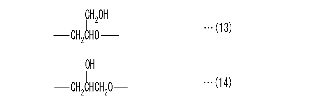
上記(c)ポリグリシドール誘導体は、下記式(13)で示される単位(以下、A単位という)と、下記式(14)で示される単位(以下、B単位という)とを有し、分子鎖の各末端が所定の置換基により封鎖されたものである。
【0043】
【化11】
【0044】
ここで、上記ポリグリシドールは、グリシドールまたは3−クロロ−1,2−プロパンジオールを重合させることにより得ることができるが、一般的には、グリシドールを原料とし、塩基性触媒またはルイス酸触媒を用いて重合を行うことが好ましい。
【0045】
上記ポリグリシドールは、分子中にA,B二つの単位を両者合わせて2個以上、好ましくは6個以上、より好ましくは10個以上有するものである。この場合、上限は特に制限されないが、通常10,000個以下程度である。これら各単位の合計数は、必要とするポリグリシドールの流動性および粘性等を考慮して適宜設定すればよい。また、分子中のA単位とB単位との比率は、モル比でA:B=1/9〜9/1、好ましくは3/7〜7/3である。なお、A,B単位の出現には規則性はなく、任意の組み合わせが可能である。
【0046】
さらに、上記ポリグリシドールにおけるゲル濾過クロマトグラフィー(GPC)を用いたポリエチレングリコール換算の重量平均分子量(Mw)が好ましくは200〜730,000、より好ましくは200〜100,000、さらに好ましくは600〜20,000のものである。また、平均分子量比(Mw/Mn)が1.1〜20、より好ましくは1.1〜10である。
【0047】
これら上記高分子化合物(a)〜(c)は、分子中の水酸基の一部または全部、好ましくは10モル%以上をハロゲン原子、炭素数1〜10の非置換または置換一価炭化水素基、R5CO−基(R5は炭素数1〜10の非置換または置換一価炭化水素基)、R5 3Si−基(R5は上記と同じ)、アミノ基、アルキルアミノ基およびリン原子を有する基から選ばれる1種または2種以上の一価の置換基により封鎖し、水酸基封鎖ポリマー誘導体とすることができる。
【0048】
ここで、炭素数1〜10の非置換または置換の一価炭化水素基としては、例えば、メチル基、エチル基、プロピル基、イソプロピル基、t−ブチル基、ペンチル基等のアルキル基、フェニル基、トリル基等のアリール基、ベンジル基等のアラルキル基、ビニル基等のアルケニル基、これらの基の水素原子の一部または全部をハロゲン原子、シアノ基、水酸基、アミノ基等で置換したもの等が挙げられ、これらの1種を単独でまたは2種以上を組み合わせて用いることができる。
【0049】
この場合、上記高分子化合物(a)〜(c)の水酸基を極性の高い置換基で封鎖すれば、高分子のマトリックスの極性が高まる(誘電率が高まる)ため、低誘電率の高分子マトリックス中で起こり易い、解離したカチオンと対アニオンとの再結合による導電性の低下を防止することができ、また、難燃性、疎水性を有する置換基で封鎖すれば、上記高分子化合物に、疎水性、難燃性などの特性を付与することができる。
【0050】
上記高分子化合物(a)〜(c)の誘電率を上げるためには、オキシアルキレン鎖を持つ高分子化合物(a)〜(c)と、水酸基反応性の化合物とを反応させることにより、この高分子化合物の水酸基を高極性の置換基で封鎖する。
このような高極性の置換基としては、特に制限されるものではないが、イオン性の置換基より中性の置換基の方が好ましく、例えば、炭素数1〜10の非置換または置換一価炭化水素基、R5CO−基(R5は上記と同じ)などが挙げられる。また、必要に応じてアミノ基、アルキルアミノ基などで封鎖することもできる。
【0051】
一方、高分子化合物(a)〜(c)に疎水性、難燃性を付与する場合には、上記高分子化合物の水酸基をハロゲン原子、R5 3Si−基(R5は上記と同じ)、リン原子を有する基などで封鎖すればよい。
R5 3Si−基としては、R5が炭素数1〜10(好ましくは1〜6)の上記と同様の非置換または置換一価炭化水素基が挙げられ、好ましくはR5はアルキル基であり、トリアルキルシリル基、中でもトリメチルシリル基が好ましい。
また、上記置換基は、アミノ基、アルキルアミノ基、リン原子を有する基などであってもよい。
【0052】
なお、上記置換基による末端封鎖率は10モル%以上であることが好ましく、より好ましくは50モル%以上、さらに好ましくは90モル%以上であり、実質的に全ての末端を上記置換基にて封鎖する(封鎖率約100モル%)こともできる。
【0053】
上記(d)シアノ基置換一価炭化水素基置換ポリビニルアルコール誘導体としては、上述の一般式(12)で示される分子中にポリビニルアルコール単位を有する平均重合度20以上の高分子化合物における上記ポリビニルアルコール単位中の水酸基の一部または全部が、シアノ基置換一価炭化水素基で置換されたものを好適に用いることができる。
この高分子化合物は、側鎖が比較的短いものであるため、電解質の粘度を低く抑えることができる。
【0054】
このような高分子化合物としては、シアノエチル基、シアノベンジル基、シアノベンゾイル基等で水酸基の一部または全部が置換されたポリビニルアルコールが挙げられ、側鎖が短いという点を考慮すると、特にシアノエチルポリビニルアルコールが好適である。
なお、ポリビニルアルコールの水酸基をシアノ基置換一価炭化水素基で置換する手法としては、公知の種々の方法を採用できる。
【0055】
上記(e)熱可塑性ポリウレタンとしては、(A)ポリオール化合物と、(B)ポリイソシアネート化合物と、必要に応じて(C)鎖伸長剤とを反応させてなる熱可塑性ポリウレタン系樹脂を用いることが好ましい。
なお、熱可塑性ポリウレタン系樹脂には、ウレタン結合を有するポリウレタン樹脂以外にも、ウレタン結合とウレア結合とを有するポリウレタンウレア樹脂も含まれる。
【0056】
(A)成分のポリオール化合物としては、ポリエーテルポリオール,ポリエステルポリオール,ポリエステルポリエーテルポリオール,ポリエステルポリカーボネートポリオール,ポリカプロラクトンポリオール、またはこれらの混合物を用いることが好ましい。
このような(A)成分のポリオール化合物の数平均分子量は1,000〜5,000であることが好ましく、より好ましくは1,500〜3,000である。ポリオール化合物の数平均分子量が小さすぎると、得られる熱可塑性ポリウレタン系樹脂フィルムの耐熱性、引張り伸び率などの物理特性が低下する場合がある。一方、大きすぎると、合成時の粘度が上昇し、得られる熱可塑性ポリウレタン系樹脂の製造安定性が低下する場合がある。なお、ここでいうポリオール化合物の数平均分子量は、いずれもJIS K1577に準拠して測定した水酸基価に基づいて算出した数平均分子量を意味する。
【0057】
(B)成分のポリイソシアネート化合物としては、例えば、トリレンジイソシアネート,4,4′−ジフェニルメタンジイソシアネート,p−フェニレンジイソシアネート,1,5−ナフチレンジイソシアネート,キシリレンジイソシアネート等の芳香族ジイソシアネート類、ヘキサメチレンジイソシアネート,イソホロンジイソシアネート,4,4′−ジシクロヘキシルメタンジイソシアネート,水添化キシリレンジイソシアネート等の脂肪族または脂環式ジイソシアネート類等が挙げられる。
【0058】
(C)成分の鎖伸長剤としては、イソシアネート基および反応性の活性水素原子を分子中に2個有し、かつ分子量が300以下である低分子量化合物を用いることが好ましい。
このような低分子量化合物としては、公知の種々の化合物を使用でき、例えば、エチレングリコール,プロピレングリコール,1,3−プロパンジオール等の脂肪族ジオール、1,4−ビス(β−ヒドロキシエトキシ)ベンゼン,1,4−シクロヘキサンジオール,ビス(β−ヒドロキシエチル)テレフタレート等の芳香族ジオールまたは脂環式ジオール、ヒドラジン,エチレンジアミン,ヘキサメチレンジアミン,キシリレンジアミン等のジアミン、アジピン酸ヒドラジド等のアミノアルコール等が挙げられ、これらの1種を単独でまたは2種以上を組合わせて用いることができる。
【0059】
なお、上記熱可塑性ポリウレタンにおいては、(A)成分のポリオール化合物100重量部に対して(B)成分のポリイソシアネート化合物を5〜200重量部、好ましくは20〜100重量部添加し、(C)成分の鎖伸長剤を1〜200重量部、好ましくは5〜100重量部添加する。
【0060】
以上説明したように本発明の非水電解質と、高分子化合物とを混合することにより得られる高分子電解質によれば、上述したイオン性液体とこれよりも貴な電位で還元分解される化合物を含んでいるため、サイクル劣化が少なく安定性に優れ、しかも低温特性に優れた非水電解質二次電池を得ることができる。
また、上記非水電解質は、上述した高分子化合物を含んでいるから、高いイオン導電性を発現できるとともに、バインダー成分としての役割や、正負極を強固に接着する機能をも充分に発揮することができる。
【0061】
また、上述した本発明の非水電解質には、分子内に反応性二重結合を有する化合物を添加し、これを反応、固化させて高分子電解質として使用することも可能である。なお、本発明における固化とは、ゲル化をも含む概念である。
すなわち、上記組成物を固化またはゲル化させて得られる非水電解質を薄膜に形成して二次電池の電解質として用いる場合に、形状保持性などの物理的強度を高める点から、分子中に反応性二重結合を有する化合物を添加し、この化合物の反応により高分子を形成させ、電解質の形状保持能力を高めるものである。
特に、上記分子中に反応性二重結合を有する化合物中における反応性二重結合の数が2個以上であると、この化合物の反応により三次元網目構造が形成されるから、より一層電解質の形状保持能力を高めることができ、好適である。
【0062】
さらに、本発明の非水電解質に、上記反応性二重結合に加えて上述した高分子化合物を添加した場合には、反応性二重結合を有する化合物が架橋してなるポリマーの三次元網目構造に、この高分子化合物の分子鎖が相互に絡みついた半相互侵入高分子網目(semi−Interpenetrating Polymer Network;(semi−IPN))構造を有する電解質が得られ、電解質の形状保持能力および強度を一層高めることができるとともに、接着性、イオン電導度をも高めることができる。
【0063】
ここで、分子内に反応性二重結合を有する化合物としては、特に限定されるものではなく、例えば、グリシジルメタクリレート、グリシジルアクリレート、メタクリル酸メトキシジエチレングリコール、メタクリル酸メトキシトリエチレングリコール、メタクリル酸メトキシポリエチレングリコール(平均分子量200〜1200)等のアクリル酸またはメタクリル酸エステル、メタクリロイルイソシアネート、2−ヒドロキシメチルメタクリル酸、N,N−ジメチルアミノエチルメタクリル酸等の分子中にアクリル酸基またはメタクリル酸基を1つ有する化合物が挙げられる。
なお、これらの反応性二重結合を1つ有する化合物と上述した高分子化合物とを用いてsemi−IPN構造を形成する場合には、後述する分子中に反応性二重結合を2個以上有する化合物を添加する必要がある。
【0064】
また、例えば、ジビニルベンゼン、ジビニルスルホン、メタクリル酸アリル、ジメタクリル酸エチレングリコール、ジメタクリル酸ジエチレングリコール、ジメタクリル酸トリエチレングリコール、ジメタクリル酸ポリエチレングリコール(平均分子量200〜1000)、ジメタクリル酸1,3−ブチレングリコール、ジメタクリル酸1,6−ヘキサンジオール、ジメタクリル酸ネオペンチルグリコール、ジメタクリル酸ポリプロピレングリコール(平均分子量400)、2−ヒドロキシ−1,3−ジメタクリロキシプロパン、2,2−ビス−[4−(メタクリロキシエトキシ)フェニル]プロパン、2,2−ビス−[4−(メタクリロキシエトキシ・ジエトキシ)フェニル]プロパン、2,2−ビス−[4−(メタクリロキシエトキシ・ポリエトキシ)フェニル]プロパン、ジアクリル酸エチレングリコール、ジアクリル酸ジエチレングリコール、ジアクリル酸トリエチレングリコール、ジアクリル酸ポリエチレングリコール(平均分子量200〜1000)、ジアクリル酸1,3−ブチレングリコール、ジアクリル酸1,6−ヘキサンジオール、ジアクリル酸ネオペンチルグリコール、ジアクリル酸ポリプロピレングリコール(平均分子量400)、2−ヒドロキシ−1,3−ジアクリロキシプロパン、2,2−ビス−[4−(アクリロキシエトキシ)フェニル]プロパン、2,2−ビス−[4−(アクリロキシエトキシ・ジエトキシ)フェニル]プロパン、2,2−ビス−[4−(アクリロキシエトキシ・ポリエトキシ)フェニル]プロパン、トリメチロールプロパントリアクリレート、トリメチロールプロパントリメタクリレート、テトラメチロールメタントリアクリレート、テトラメチロールメタンテトラアクリレート、水溶性ウレタンジアクリレート、水溶性ウレタンジメタクリレート、トリシクロデカンジメタノールアクリレート、水素添加ジシクロペンタジエンジアクリレート、ポリエステルジアクリレート、ポリエステルジメタクリレート等の分子中に反応性二重結合を2個以上有する化合物が好適に用いられる。
【0065】
上記反応性二重結合を含有する化合物の中でも特に好ましい反応性モノマーとしては、下記一般式(15)で示されるポリオキシアルキレン成分を含有するジエステル化合物が挙げられ、これと下記一般式(16)で示されるポリオキシアルキレン成分を含有するモノエステル化合物、およびトリエステル化合物とを組み合わせて用いることが推奨される。
【0066】
【化12】
(但し、式中、R6〜R8は、水素原子、またはメチル基、エチル基、n−プロピル基、i−プロピル基、n−ブチル基、i−ブチル基、s−ブチル基、t−ブチル基等の炭素数1〜6、特に1〜4のアルキル基を示し、X≧1かつY≧0の条件を満足するものか、またはX≧0かつY≧1の条件を満足するものであり、好ましくはR6〜R8は、メチル基、エチル基、n−プロピル基、i−プロピル基、n−ブチル基、i−ブチル基、s−ブチル基、t−ブチル基である。)
【0067】
【化13】
(但し、式中、R9〜R11は、水素原子、またはメチル基、エチル基、n−プロピル基、i−プロピル基、n−ブチル基、i−ブチル基、s−ブチル基、t−ブチル基等の炭素数1〜6、特に1〜4のアルキル基を示し、A≧1かつB≧0の条件を満足するものか、またはA≧0かつB≧1の条件を満足するものであり、好ましくはR9〜R11は、メチル基、エチル基、n−プロピル基、i−プロピル基、n−ブチル基、i−ブチル基、s−ブチル基、t−ブチル基である。)
【0068】
上記式(15)において、例えば、X=9、Y=0、R6=R8=CH3が好ましく用いられる。一方。上記式(16)において、例えばA=2または9、B=0、R9=R11=CH3が好ましく用いられる。
また、トリエステル化合物としては、トリメチロールプロパントリメタクリレートが好適である。
【0069】
上記ポリオキシアルキレン成分を含有するジエステル化合物とポリオキシアルキレン成分を含有するモノエステル化合物は、上記イオン性液体と、このイオン性液体より貴な電位で還元分解される化合物と、リチウム塩と、高分子化合物との混合物中で紫外線、電子線、X線、γ線、マイクロ波、高周波などを照射することにより、または混合物を加熱することにより、semi−IPN構造の三次元架橋ネットワーク構造を形成する。
【0070】
ここで、上記ポリオキシアルキレン成分を含有するジエステル化合物およびモノエステル化合物と、トリエステル化合物との組成比は、ポリオキシアルキレン成分の長さによって適宜設定されるものであり、特に限定されるものではないが、モル比で、
〔ジエステル化合物/モノエステル化合物〕=0.1〜2、特に0.3〜1.5
〔ジエステル化合物/トリエステル化合物〕=2〜15、特に3〜10
の範囲内が電解質の強度向上という点から見て好ましい。
【0071】
以上説明したように、本発明の非水電解質と、反応性二重結合を有する化合物とを含む組成物を固化(ゲル化)させて得られる高分子電解質は、上述したイオン性液体と、これよりも貴な電位で還元分解される化合物とを含むので、低温特性、サイクル特性、イオン導電性、粘着性等の上述した特性を有するのみならず、高い形状保持能力をも有するものである。
特に、分子中に反応性二重結合を有する化合物として、反応性二重結合を2個以上有するものを用いるとともに、上述した高分子化合物をも含む組成物を固化させた電解質は、semi−IPN構造の三次元架橋ネットワーク構造を有するため、電解質の形状保持能力および強度を一層高めることができるとともに、接着性、イオン電導度をも一層高めることができる。
【0072】
本発明に係る二次電池は、リチウム含有複合酸化物を含む正極と、リチウムイオンを吸蔵・放出する炭素質材料または金属リチウムを含む負極と、これらの正負極間に介在させたセパレータと、非水電解質とを備えて構成された二次電池において、非水電解質として、上述した非水電解質または高分子電解質を用いたものである。
【0073】
上記正極としては、正極集電体の表裏両面または片面に、バインダーポリマーと正極活物質とを主成分として含む正極用バインダー組成物を塗布してなるものを用いることができる。
なお、バインダーポリマーと正極活物質とを主成分として含む正極用バインダー組成物を溶融混練した後、押出し、フィルム成形することにより正極を形成することもできる。
【0074】
上記バインダーポリマーとしては、当該用途に使用できるポリマーであれば特に限定はないが、例えば、(I)下記式から求めた膨潤率が150〜800重量%の範囲である熱可塑性樹脂、(II)フッ素系高分子材料等を1種単独で、または(I),(II)の2種以上を組み合わせて用いることが好ましい。
また、上記(I)の熱可塑性樹脂は、下記式から求めた膨潤率が150〜800重量%の範囲であり、より好ましくは250〜500重量%、さらに好ましくは250〜400重量%である。
【0075】
【数1】
【0076】
上記(I)のバインダーポリマーとしては、下記一般式(3)で表わされる単位を含む熱可塑性樹脂を用いることができる。
【0077】
【化14】
(式中、rは3〜5、sは5以上の整数を示す。)
【0078】
次に、上記(II)のバインダーポリマーであるフッ素系高分子材料としては、例えば、ポリフッ化ビニリデン(PVDF)、フッ化ビニリデンとヘキサフルオロプロピレンとの共重合体〔P(VDF−HFP)〕、フッ化ビニリデンと塩化3フッ化エチレンとの共重合体〔P(VDF−CTFE)〕等が好ましく用いられる。これらの内でも、フッ化ビニリデンが50重量%以上、特に70重量%以上(上限値は97重量%程度である)であるものが好適である。
この場合、フッ素系ポリマーの重量平均分子量は、特に限定はないが、500,000〜2,000,000が好ましく、より好ましくは500,000〜1,500,000である。重量平均分子量が小さすぎると物理的強度が著しく低下する場合がある。
【0079】
上記正極集電体としては、ステンレス鋼、アルミニウム、チタン、タンタル、ニッケル等を用いることができる。これらの中でも、アルミニウム箔または酸化アルミニウム箔が性能と価格との両面から見て好ましい。この正極集電体は、箔状、エキスパンドメタル状、板状、発泡状、ウール状、ネット状等の三次元構造などの種々の形態のものを採用することができる。
【0080】
本発明では、上記正極活物質として、リチウムイオン含有カルコゲン化合物(リチウム含有複合酸化物)が用いられる。
ここで、リチウムイオン含有カルコゲン化合物(リチウム含有複合酸化物)としては、例えば、LiCoO2、LiMnO2、LiMn2O4、LiMo2O4、LiV3O8、LiNiO2、LixNiyM1−yO2(但し、Mは、Co,Mn,Ti,Cr,V,Al,Sn,Pb,Znから選ばれる少なくとも1種以上の金属元素を表し、0.05≦x≦1.10、0.5≦y≦1.0)等が挙げられる。
【0081】
なお、正極用バインダー組成物には、上述のバインダー樹脂および正極活物質以外にも、必要に応じて導電材を添加することができる。導電材としては、カーボンブラック、ケッチェンブラック、アセチレンブラック、カーボンウイスカー、炭素繊維、天然黒鉛、人造黒鉛などが挙げられる。
【0082】
上記正極用バインダー組成物において、バインダー樹脂100重量部に対して正極活物質の添加量は1,000〜5,000重量部、好ましくは1,200〜3,500重量部であり、導電材の添加量は20〜500重量部、好ましくは50〜400重量部である。
【0083】
一方、上記負極は、リチウム金属からなる負極、または負極集電体の表裏両面もしくは片面に、バインダーポリマーと負極活物質とを主成分として含む負極用バインダー組成物を塗布してなるものである。ここで、バインダーポリマーとしては、正極と同じものを用いることができる。
なお、バインダーポリマーと負極活物質とを主成分として含む負極用バインダー組成物を溶融混練した後、押出し、フィルム成形することにより負極を形成してもよい。
【0084】
負極集電体としては、銅、ステンレス鋼、チタン、ニッケルなどが挙げられ、これらの中でも、銅箔または表面が銅メッキ膜にて被覆された金属箔が性能と価格との両面から見て好ましい。この集電体は、箔状、エキスパンドメタル状、板状、発泡状、ウール状、ネット状等の三次元構造などの種々の形態のものを採用することができる。
【0085】
上記負極活物質としては、リチウムイオンを可逆的に吸蔵、放出する炭素質材料を用いる。
この炭素質材料としては、難黒鉛化炭素系材料や黒鉛系材料等の炭素質材料を使用することができる。より具体的には、熱分解炭素類、コークス類(ピッチコークス、ニートルコークス、石油コークス)、黒鉛類、ガラス状炭素類、有機高分子化合物焼成体(フェノール樹脂、フラン樹脂等を適当な温度で焼成し炭素化したもの)、炭素繊維、活性炭等の炭素質材料を使用することができる。
なお、負極用バインダー組成物にも、必要に応じて導電材を添加することができる。導電材としては、上述の正極用バインダー組成物と同様のものが挙げられる。
【0086】
上記負極用バインダー組成物において、バインダーポリマー100重量部に対して負極活物質の添加量は500〜1,700重量部、好ましくは700〜1,300重量部であり、導電材の添加量は0〜70重量部、好ましくは0〜40重量部である。
【0087】
上記負極用バインダー組成物および正極用バインダー組成物は、通常、分散媒を加えてペースト状で用いられる。分散媒としては、例えば、N−メチル−2−ピロリドン(NMP)、ジメチルホルムアミド、ジメチルアセトアミド、ジメチルスルホアミド等の極性溶媒が挙げられる。この場合、分散媒の添加量は、正極用または負極用バインダー組成物100重量部に対して30〜300重量部程度である。
【0088】
なお、正極および負極を薄膜化する方法としては、特に制限されないが、例えば、アプリケータロール等のローラーコーティング、スクリーンコーティング、ドクターブレード法、スピンコーティング、バーコーター等の手段を用いて、乾燥後における活物質層の厚さを10〜200μm、特に15〜100μmの均一な厚みに形成することが好ましい。
【0089】
また、正負極間に介在されるセパレータとしては、特に限定はなく、例えば、ポリエチレン不織布、ポリプロピレン不織布、ポリエステル不織布、PTFE多孔体フィルム、クラフト紙、レーヨン繊維・サイザル麻繊維混抄シート、マニラ麻シート、ガラス繊維シート、セルロース系電解紙、レーヨン繊維からなる抄紙、セルロースとガラス繊維との混抄紙、またはこれらを組み合わせて複数層に構成したものなどを使用することができる。
なお、セパレータの構造としては、特に限定されるものではなく、単層構造のものでもよく、複数のフィルムまたはシートを積層した多層構造のものを用いてもよい。
【0090】
セパレータの形態としては、厚み20〜50μm、空孔率25〜85%の多孔性フィルムまたは多孔性シートであることが好ましい。ここで、厚みが、20μm未満の場合、電池の内部短絡の発生率が高くなる虞があり、一方、50μmを超えた場合、電池の放電負荷特性が悪化する虞がある。これらを考慮すると、セパレータの厚みは、25〜40μm、特に、25〜35μmであることが好ましい。
【0091】
一方、空孔率が、空孔率が25%未満の場合、電解質溶液の浸透性が悪くなる虞があるとともに、同体積あたりの電解質溶液の量が減少するのでイオンの伝導率が低下し、電池特性が悪くなる虞がある。一方、85%を超えた場合、電池の大電流放電特性は向上するものの、物理的強度が低下するため、組立作業時の取り扱い性が悪くなる虞があるとともに、内部短絡の発生率が高まる虞がある。これらを考慮すると、セパレータの空孔率は、25〜85%、より好ましくは50〜80%、特に、65〜75%であることが好適である。上記厚みおよび空孔率を満たすセパレータを用いることで、大電流放電特性に優れた非水電解質二次電池を得ることができる。
【0092】
このような多孔性フィルムまたは多孔性シートの材質としては、特に限定されるものではなく、上述した各種材質のセパレータを使用することができるが、中でも、セルロースを主成分とする多孔性フィルムまたは多孔性シートを用いることが好ましい。なお、「主成分」とは、セパレータ中にセルロースが、乾燥状態、すなわち、水分を除去した状態で、95重量%以上程度含まれることを意味する。
【0093】
このようなセルロースを主成分とする多孔性フィルムまたは多孔性シートを用いることで、非水電解質二次電池の充電特性、レート特性、安全性、電池生産性を向上させることができるとともに、過充電特性をも高めることができる。
ここで、セルロースを含む多孔性フィルムまたは多孔性シートとしては、特に限定されるものではないが、製造コスト、電解質溶液に対する親液性、電池特性等を考慮すると、セルロース繊維を抄紙して得られる紙を用いることが好ましい。なお、セルロース繊維を叩解して得られる紙も使用することができる。
上記セルロースは、200℃以上の耐熱性を有しており、ポリオレフィン系樹脂よりも熱安定性に優れているため、電池の熱安定性を向上させることができ、結果として、セパレータの熱収縮による内部短絡等による異常過熱の危険性を回避することができる。
【0094】
また、セルロースを主成分とするセパレータを用いた場合、セルロース分子中の水酸基と極性の高い電解質分子とが強く相互作用するため、ポリオレフィン系セパレータと比べ親液性が向上する。このため、電解質溶液の浸透速度が大きく、電池組み立て時の作業効率が向上するとともに、セパレータが電解質溶液に浸らない部分があるために起こる電池性能の劣化が生じることもない。
しかも、表面積の大きなセルロース繊維の表面が電解質溶液と相互作用するため、電解質の保持性も高くなることから、離液も生じにくくなり、結果として、電池の充放電特性、高温保持特性、安全性の向上を図ることもできる。
【0095】
本発明の二次電池は、上述した正極と負極との間にセパレータを介在させてなる電池構造体を、積層、折畳、または捲回させて、さらにラミネート型やコイン型に形成し、これを電池缶またはラミネートパック等の電池容器に収容し、電池缶であれば封缶、ラミネートパックであればヒートシールすることで、組み立てられる。この場合、セパレータを正極と負極との間に介在させ、電池容器に収容した後、非水電解液を充填することとなる。なお、非水電解質として反応性二重結合を有する化合物を用いる場合には、電解質用組成物を充填し、電極間、セパレータと電極間の空隙に十分に浸透させた後に反応硬化させればよい。
【0096】
このようにして得られる本発明の非水電解質二次電池は、充放電効率、エネルギー密度、出力密度、寿命等の優れた特性を損なうことなく、高容量、高電流で作動でき、しかも、使用温度範囲の広いものである。
また、本発明の非水電解質二次電池は、ビデオカメラ、ノート型パソコン、携帯電話,PHS(登録商標)等の携帯端末などの主電源、メモリのバックアップ電源用途をはじめとして、パソコン等の瞬時停電対策用電源、電気自動車またはハイブリッド自動車への応用、太陽電池と併用したソーラー発電エネルギー貯蔵システム等の様々な用途に好適に使用することができる。
【0097】
【実施例】
以下、合成例、実施例および比較例を挙げて、本発明をより具体的に説明するが、本発明は下記の実施例に制限されるものではない。
なお、実施例1〜8および比較例1、2までは、本発明の電解質溶液の負極側での性能をみる目的で、対極にリチウム金属を用いた。この場合、慣用的には炭素質負極は正極となるが、放電時にリチウムイオンを受け取って還元されるため、ここでは負極と呼び、還元方向を充電と呼ぶことにした。
【0098】
[合成例1] 化合物(8)の合成
【0099】
【化15】
【0100】
ジエチルアミン(関東化学(株)製)100mlと2−メトキシエチルクロライド(関東化学(株)製)85mlとを混合し、得られた混合溶液をオートクレーブ中に入れ、100℃で24時間反応させた。この時、内圧は、0.127MPa(1.3kgf/cm2)であった。24時間後、析出した結晶と反応液との混合物に水酸化カリウム(片山化学工業(株)製)56gを溶解した水溶液200mlを加え、2層に別れた有機層を分液ロートで分液した。さらに、塩化メチレン(和光純薬工業(株)製)100mlを加え抽出する操作を2回行った。分液した有機層をまとめ、飽和食塩水で洗浄した後、炭酸カリウム(和光純薬工業(株)製)を加えて乾燥し、減圧濾過した。得られた有機層の溶媒をロータリーエバポレーターを用いて留去し、残留分について常圧蒸留を行い、沸点135℃付近の留分を18.9g得た。この化合物が2−メトキシエチルジエチルアミンであることを1H−核磁気共鳴スペクトル(以下、NMRという)により確認した。
【0101】
得られた2−メトキシエチルジエチルアミン8.24gをテトラヒドロフラン(和光純薬工業(株)製)10mlに溶解し、氷冷下、ヨウ化メチル(和光純薬工業(株)製)4.0mlを加えた。30分後、アイスバスを外し、室温にて一晩撹拌した。この反応溶液の溶媒を減圧留去し、得られた固形分をエタノール(和光純薬工業(株)製)−テトラヒドロフラン系で再結晶し、2−メトキシエチルジエチルメチルアンモニウムヨウ素塩を16g得た。
【0102】
続いて、2−メトキシエチルジエチルメチルアンモニウムヨウ素塩10.0gをアセトニトリル(関東化学(株)製)50mLに溶解した。これにトリフルオロメタンスルホン酸イミドリチウム(キシダ化学(株)製)9.5gを加え、これが完全に溶解した後、さらに15分間撹拌した。
アセトニトリルを減圧留去し、残留分に水を加え、2層に分離した有機層を分液し、水で5回洗浄し、有機層中の不純物を取り除いた。
洗浄後の有機層を真空ポンプにて減圧にし、水を十分に留去し、室温で液体状の化合物(8)を6.8g得た。
【0103】
[合成例2] 化合物(3)の合成
【0104】
【化16】
【0105】
合成例1と同様にして得られた2−メトキシエチルジエチルアミン8.24gをテトラヒドロフラン(和光純薬工業(株)製)10mlに溶解し、氷冷下、ヨウ化メチル(和光純薬工業(株)製)4.0mlを加えた。30分後、アイスバスを外し、室温にて一晩撹拌した。この反応溶液の溶媒を減圧留去し、得られた固形分をエタノール(和光純薬工業(株)製)−テトラヒドロフラン系で再結晶し、2−メトキシエチルジエチルメチルアンモニウムヨウ素塩を16g得た。
続いて、2−メトキシエチルジエチルメチルアンモニウムヨウ素塩15.0gを蒸留水100mlに溶解し、酸化銀(関東化学(株)製)6.37gを加え、3時間撹拌した。この反応混合物を減圧濾過して、沈殿物を取り除いた後、撹拌下、42%テトラフルオロホウ酸(関東化学(株)製)を反応液がpH5〜6付近になるまで少量ずつ加えた。この反応溶液を凍結乾燥し、さらに真空ポンプで水を十分留去し、室温(25℃)で液体状の化合物(3)を12.39g得た。
【0106】
[合成例3]
トリフルオロメタンスルホン酸イミドリチウム(キシダ化学(株)製)5.74gを、クロロホルムとアセトニトリルとの1:1(体積比)混合溶媒30mlに添加して攪拌し、懸濁液を調製した後、この懸濁液に1−エチル−3−メチルイミダゾリウムクロリド(東京化成工業(株)製)2.92gをクロロホルムとアセトニトリルとの1:1(体積比)混合溶媒30mlに溶解させた溶液を添加し、80分間攪拌した。生成した結晶を減圧濾過で除去し、濾液中の溶媒をエバポレータおよび真空ポンプで留去した。
得られた残留分4.85gをさらにシリカゲルカラムクロマトグラフィー(ワコーゲル C−200、和光純薬工業(株)製、溶出液:クロロホルムとメタノールとの1:1(体積比)混合溶媒)にて精製し、室温で液状のイミダゾリウム系イオン性液体3.06gを得た。
【0107】
[合成例4]
攪拌機、温度計および冷却管を備えた反応器に、予め加熱脱水したポリエチレングリコール4000(PEG4000−S、三洋化成工業(株)製)60.20重量部と、4,4’−ジフェニルメタンジイソシアネート7.84重量部とを仕込み、窒素気流下、120℃で2時間攪拌、混合した後、1,4−ブタンジオール1.86重量部を加えて、同様に窒素気流下、120℃にて反応させた。反応が進行し、反応物がゴム状になった時点で反応を停止した。その後、反応物を反応器から取り出し、100℃で12時間加熱し、赤外線吸収スペクトルでイソシアネート基の吸収ピークが消滅したのを確認して加熱をやめ、固体状のポリウレタン樹脂を得た。
得られたポリウレタン樹脂の重量平均分子量(Mw)は1.05×10⁵であった。このポリウレタン樹脂8重量部をN−メチル−2−ピロリドン92重量部に溶解することによって、ポリウレタン樹脂溶液を得た。
【0108】
[参考例1]電位窓測定
上記合成例1、合成例2、合成例3で得られたそれぞれの化合物および1−エチル−3−メチルイミダゾリウムテトラフルオロボレート(関東化学(株)製)について、サイクリックボルタンメトリー装置を使用し、作用極として白金電極(電極面積1.76mm2)、対極として白金電極(電極面積400mm2)、参照極に銀/塩化銀電極を使用し、掃引速度1mV/秒の条件でサイクリックボルタンメトリー測定を行った。測定の結果得られた電位窓のデータを図1に示す。
【0109】
[実施例1]評価電池1
〈炭素質負極の作製〉
炭素質負極活物質としてMCMB(MCMB6−28、大阪ガスケミカル(株)製)92重量部、およびポリフッ化ビニリデン10重量部をN−メチル−2−ピロリドン90重量部に溶解した溶液80重量部と、N−メチル−2−ピロリドン40重量部とを攪拌・混合し、ペースト状の炭素質負極用組成物を得た。この炭素質負極用組成物を、銅箔上にドクターブレードにより塗布した後、80℃で2時間乾燥し、電極の厚みが30μmとなるようにロールプレスして炭素質負極を作製した。
【0110】
〈電解液の調製〉
電解液として合成例1で得られたイオン性液体96重量部にトリフルオロメタンスルホン酸イミドリチウム4重量部を溶解させ、これに対してビニレンカーボネート10重量部を添加した溶液を調製した。
〈評価電池の作製〉
上記で作製した炭素質負極を12mmφに、セパレータ(ポリオレフィン多孔膜E25MMS、東燃タピルス(株)製)を13mmφにそれぞれ切り取り、上記で調製した電解液に浸し、30分間減圧することにより液を含浸させた。電解液を含浸させた炭素質負極と12mmφの円板状に打ち抜いたリチウム金属を、電解液を含浸させたセパレータを介して積層し外装ケースで密閉することにより評価電池を作製した。なお、本実施例で使用したポリオレフィン多孔膜の厚みおよび空孔率を測定したところ、厚みが25μm、空孔率が26.6%であった。
ここで、セパレータの厚みは、1/10000シックネスゲージを用いて測定した。空孔率は、セパレータを直径3cmの円状に切り抜き、空気中における体積と重量とをそれぞれ求め、次式を用いて算出した値である(以下の各実施例におけるセパレータの厚み、空孔率も同様の方法により求めた値である)。
空孔率(%)=100×{(体積−重量)/(セパレータの樹脂成分の比重)}/体積
なお、上記セパレータの樹脂成分の比重は、JIS K 7112記載の水中置換法により、セパレータの空気中での重量とセパレータを水中に浸漬した時の重量より、以下の式により算出した値である。
セパレータの樹脂成分の比重=(セパレータの空気中での重量)/{(セパレータの空気中での重量)−(セパレータを水中に浸漬したときの重量)}
【0111】
〈充放電試験〉
製作した評価電池について、充電電圧を10mV、放電電圧を1.5Vに設定し、電流密度0.03mA/cm2の定電流で充放電試験を行った結果、炭素質負極の充電容量297mAh/g、1サイクル目の充放電効率83.3%となった。
【0112】
[比較例1]評価電池2
電解液を合成例1で得られたイオン性液体96重量部にトリフルオロメタンスルホン酸イミドリチウム4重量部を溶解させた溶液を用いた以外は、実施例1と同様にして評価電池を作製した。
〈充放電試験〉
作製した評価電池について実施例1と同様に充放電試験を行った結果、炭素質負極の容量151mAh/g、1サイクル目の充放電効率45.7%となった。
実施例1と比較例1の1サイクル目の充電曲線を図2に示す。
【0113】
[比較例2]評価電池3
電解液として合成例3で得られたイオン性液体96重量部にトリフルオロメタンスルホン酸イミドリチウム4重量部を溶解させ、それに対してビニレンカーボネート10重量部を添加した溶液を用いた以外は、実施例1と同様にして評価電池を作製した。
〈充放電試験〉
作製した評価電池について、実施例1と同様の充放電試験を行った結果、炭素質負極の容量243mAh/g、1サイクル目の充放電効率68.2%となった。
【0114】
[実施例2]評価電池4
電解液として合成例1で得られたイオン性液体96重量部にトリフルオロメタンスルホン酸イミドリチウム4重量部を溶解させ、それに対してビニレンカーボネート5重量部を添加した溶液を用いた以外は、実施例1と同様にして評価電池を作製した。
〈充放電試験〉
作製した評価電池について実施例1と同様に充放電試験を行った結果、炭素質負極の容量285mAh/g、1サイクル目の充放電効率82.7%となった。
【0115】
[実施例3]評価電池5
電解液として合成例1で得られたイオン性液体96重量部にトリフルオロメタンスルホン酸イミドリチウム4重量部を溶解させ、それに対してビニレンカーボネート1重量部を添加した溶液を用いた以外は、実施例1と同様にして評価電池を作製した。
〈充放電試験〉
作製した評価電池について実施例1と同様に充放電試験を行った結果、炭素質負極の容量279mAh/g、1サイクル目の充放電効率81.5%となった。
【0116】
[実施例4]評価電池6
電解液として合成例1で得られたイオン性液体96重量部にトリフルオロメタンスルホン酸イミドリチウム4重量部を溶解させ、それに対してエチレンカーボネート10重量部を添加した溶液を用いた以外は、実施例1と同様にして評価電池を作製した。
〈充放電試験〉
作製した評価電池について実施例1と同様に充放電試験を行った結果、炭素質負極の容量273mAh/g、1サイクル目の充放電効率79.3%となった。
【0117】
[実施例5]評価電池7
電解液として合成例1で得られたイオン性液体96重量部にトリフルオロメタンスルホン酸イミドリチウム4重量部を溶解させ、それに対してビニレンカーボネート:ジエチルカーボネート=1:1(体積比)で混合した溶液10重量部を添加した溶液を用いた以外は、実施例1と同様にして評価電池を作製した。
〈充放電試験〉
作製した評価電池について実施例1と同様に充放電試験を行った結果、炭素質負極の容量277mAh/g、1サイクル目の充放電効率80.8%となった。
【0118】
[実施例6]評価電池8
電解液として合成例1で得られたイオン性液体83重量部にトリフルオロメタンスルホン酸イミドリチウム17重量部を溶解させ、それに対してビニレンカーボネート10重量部添加した溶液を用いた以外は、実施例1と同様にして評価電池を作製した。
〈充放電試験〉
作製した評価電池について実施例1と同様に充放電試験を行った結果、炭素質負極の容量270mAh/g、1サイクル目の充放電効率78.2%となった。
【0119】
[実施例7]評価電池9
電解液として合成例2で得られたイオン性液体96重量部にテトラフルオロホウ酸リチウム4重量部を溶解させ、それに対してビニレンカーボネート10重量部添加した溶液を用いた以外は、実施例1と同様にして評価電池を作製した。
〈充放電試験〉
作製した評価電池について実施例1と同様に充放電試験を行った結果、炭素質負極の容量282mAh/g、1サイクル目の充放電効率81.9%となった。
【0120】
[実施例8]評価電池10
電解液として合成例1で得られたイオン性液体96重量部にテトラフルオロホウ酸リチウム4重量部を溶解させ、それに対してビニレンカーボネート10重量部添加した溶液を用いた以外は、実施例1と同様にして評価電池を作製した。
〈充放電試験〉
作製した評価電池について実施例1と同様に充放電試験を行った結果、炭素質負極の容量288mAh/g、1サイクル目の充放電効率82.6%となった。
【0121】
上記各実施例、比較例における炭素質負極の容量および1サイクル目の充放電効率を下記表1にまとめて示す。
【0122】
【表1】
【0123】
表1に示されるように、上記実施例1〜8で得られた評価電池は、本発明のイオン性液体およびこのイオン性液体よりも貴な電位で還元分解される化合物を含む非水電解質を用いているから、該化合物を含まない電解質を用いた比較例1の評価電池と比べ、炭素質負極容量および充放電効率が著しく高いことがわかる。
また、イミダゾリウムイオンを含むイオン性液体と上記化合物とを含む電解質を用いた比較例2の評価電池と比べても、負極容量および充放電効率とも格段に向上していることがわかる。
【0124】
[実施例9]二次電池1
〈正極の作製〉
正極活物質としてLiCoO292重量部と、導電剤としてケッチェンブラック3重量部と、ポリフッ化ビニリデン10重量部をN−メチル−2−ピロリドン90重量部に溶解した溶液50重量部と、N−メチル−2−ピロリドン20重量部とを攪拌・混合し、ペースト状の正極合剤を得た。この正極合剤をアルミ箔上にドクターブレードにより塗布した後、80℃で2時間乾燥し、電極の厚みが30μmとなるようにロールプレスして正極を作製した。
【0125】
〈炭素質負極の作製〉
炭素質負極活物質としてMCMB(MCMB6−28、大阪ガスケミカル(株)製)92重量部、およびポリフッ化ビニリデン10重量部をN−メチル−2−ピロリドン90重量部に溶解した溶液80重量部と、N−メチル−2−ピロリドン40重量部とを攪拌・混合し、ペースト状の炭素質負極用組成物を得た。この炭素質負極用組成物を銅箔上に、ドクターブレードにより塗布した後、80℃で2時間乾燥し、電極の厚みが30μmとなるようにロールプレスして炭素質負極を作製した。
〈電解液の調製〉
電解液として合成例1で得られたイオン性液体96重量部にトリフルオロメタンスルホン酸イミドリチウム4重量部を溶解させ、それに対してビニレンカーボネート10重量部を添加した溶液を調製した。
【0126】
〈二次電池の作製〉
上記で作製した正極と炭素質負極をそれぞれ11mmφ、12mmφに、セパレータ(ポリオレフィン多孔膜E25MMS、東燃タピルス(株)製)を13mmφに切り取り、上記で調製した電解液に浸し、30分間減圧することにより液を含浸させた。電解液を含浸させた正極と炭素質負極を、電解液を含浸させたセパレータを介して積層し外装ケースで密閉することにより、二次電池を作製した。
【0127】
〈充放電試験〉
製作した二次電池について、充電電圧を4.2V、放電電圧を2.7Vに設定し、電流密度0.03mA/cm2の定電流で充放電試験を行った結果、電池容量0.723mAh、1サイクル目の充放電効率76.5%となった。その後、同様の条件で20サイクルの充放電試験を行った結果、20サイクル目の放電容量維持率(1サイクル目の放電容量に対する20サイクル目の放電容量の割合)は、97.2%であった。1サイクル目の放電曲線を図3に示す。
【0128】
[実施例10]二次電池2
〈二次電池の作製〉
電解液として合成例2で得られたイオン性液体96重量部にテトラフルオロホウ酸リチウム4重量部を溶解させ、それに対してビニレンカーボネート10重量部添加した溶液を用いた以外は、実施例9と同様にして二次電池を作製した。
〈充放電試験〉
作製した二次電池について実施例9と同様の充放電試験を行った結果、電池容量0.714mAh、1サイクル目の充放電効率75.9%となった。その後実施例9と同様にして20サイクルの充放電試験を行った結果、20サイクル目の放電容量維持率は、96.8%であった。
【0129】
[実施例11]二次電池3
〈ポリウレタン樹脂膜の作製〉
合成例3で得られたポリウレタン樹脂溶液を乾燥膜厚が30μmとなるようにドクターブレードにより塗布した後、120℃で2時間減圧乾燥し、ポリウレタン樹脂膜を作成した。
〈電解液の調製〉
電解液として合成例1で得られたイオン性液体96重量部にトリフルオロメタンスルホン酸イミドリチウム4重量部を溶解させ、それに対してビニレンカーボネート10重量部を添加した溶液を調製した。
【0130】
〈二次電池の作製〉
実施例9と同様に作製した正極と炭素質負極をそれぞれ11mmφ、12mmφに切り取り、上記で調製した電解液に浸し、30分間減圧することにより液を含浸させた。さらに、上記ポリウレタン樹脂膜を13mmφに切り取り、上記で調製した電解液に24時間浸すことによって電解液を含浸させた。電解液を含浸させた正極と炭素質負極を、電解液を含浸させたポリウレタン樹脂膜を介して積層し外装ケースで密閉することにより、二次電池を作製した。
〈充放電試験〉
作製した二次電池について実施例9と同様の充放電試験を行った結果、電池容量0.708mAh、1サイクル目の充放電効率75.5%となった。その後実施例9と同様にして20サイクルの充放電試験を行った結果、20サイクル目の放電容量維持率は、96.1%であった。
【0131】
[実施例12]二次電池4
〈電解質用組成物溶液の作製〉
予め脱水処理されたポリエチレングリコールジメタクリレート(オキシレンユニット数=9)100重量部と、メトキシポリエチレングリコールモノメタクリレート(オキシレンユニット数=2)70.15重量部と、トリメチロールプロパントリメタクリレート8.41重量部とを混合し、この混合組成物14.5重量部に対し、実施例11で作製した電解質溶液を85重量部とアゾビスイソブチロニトリル0.5重量部を加えることにより電解質用組成物を調製した。
【0132】
〈二次電池の作製〉
実施例9と同様に作製した正極と炭素質負極をそれぞれ11mmφ、12mmφに切り取り、セパレータ(ポリオレフィン多孔膜E25MMS、東燃タピルス(株)製)を13mmφに切り取り、上記で調製した電解質用組成物溶液に浸し、30分間減圧することにより液を含浸させた。上記で電解質用組成物溶液を含浸させた正極と炭素質負極を、電解質用組成物溶液を含浸させたセパレータを介して積層し外装ケースで密閉し、その後55℃で2時間、80℃で0.5時間加熱しゲル化させ、二次電池を作製した。
〈充放電試験〉
作製した二次電池について実施例9と同様に充放電試験を行った結果、電池容量0.706mAh、1サイクル目の充放電効率75.0%となった。その後実施例9と同様に20サイクルの充放電試験を行った結果、20サイクル目の放電容量維持率は、95.3%であった。
【0133】
上記各実施例で得られた二次電池の放電容量、1サイクル目の充放電効率、および放電容量維持率について下記表2にまとめて示した。
【0134】
【表2】
【0135】
表2に示されるように、本発明のイオン性液体を含む電解質を含んで構成された実施例9〜12の非水電解質二次電池は、放電容量、充放電効率、および放電容量維持率に優れていることがわかる。
【0136】
[実施例13]二次電池5
〈電解液の調製〉
電解液として合成例1で得られたイオン性液体71重量部に、トリフルオロメタンスルホン酸イミドリチウム29重量部を溶解させ、それに対してビニレンカーボネート10重量部を添加した溶液を調整した。
【0137】
〈二次電池の作製〉
実施例9と同様に作製した正極と炭素質負極を電極の塗布部がそれぞれ38mm×38mm、40mm×40mmとなるように切り取り、セルロースセパレータ(TF40−30、ニッポン高度紙工業(株)製)を介して積層し、ポリプロピレン板で挟んで固定した。この積層体をラミネートでパックし、上記で調製した電解液を注液し、1時間減圧することにより電解液を含浸させた。最後に、ラミネートを真空状態で密閉してラミネート型非水電解質二次電池を作製した。なお、本実施例で使用したセルロースセパレータの厚みおよび空孔率を測定したところ、厚みが30μmで空孔率が73.1%であった。
【0138】
〈充放電試験〉
初期性能試験
上記にて作製した二次電池について、充電電圧4.2V、放電電圧2.7Vに設定し、電流密度0.076mA/cm2(0.1C相当)の条件で充放電試験を行ったところ、放電容量11.2mAh(LiCoO2当たりの容量132.6mAh/g)であり、リチウムイオン電池として良好に作動することを確認した。得られた充放電カーブを図4に示す。
【0139】
負荷特性試験
上記にて作製した二次電池について、充電電圧4.2V、放電電圧2.7Vに設定し、充電時の電流密度0.076mA/cm2(0.1C相当)、放電時の電流密度0.152mA/cm2(0.2C相当)、0.228mA/cm2(0.3C相当)、0.380mA/cm2(0.5C相当)、0.760mA/cm2(1.0C相当)の条件で充放電試験を行った結果、放電容量および0.1C放電時に対する容量比(各放電レートでの容量/0.1C放電時の容量×100%)は、それぞれ11.1mAh、99.3%、11.1mAh、99.1%、10.8mAh、96.3%、6.3mAh、56.4%であった。各電流密度における放電時の容量及び、0.1C放電時に対する容量比を表3に、得られた放電カーブを図5に示す。
【0140】
【表3】
【0141】
サイクル試験
上記にて作製した二次電池について、充電電圧4.2V、放電電圧2.7Vに設定し電流密度0.076mA/cm2(0.1C相当)の定電流の条件でサイクル試験を行った結果、100サイクル目の放電容量維持率(各サイクルの放電容量/1サイクル目の放電容量×100%)は96.9%であった。また、同様に作製した二次電池で、放電の電流密度のみ0.380mA/cm2(0.5C相当)の定電流に条件を変更してサイクル試験を行った結果は、100サイクル目の放電容量維持率96.4%であった。放電の電流密度0.076mA/cm2(0.1C相当)で行った試験の各サイクルの放電容量維持率の結果を図6に示す。なお、この結果より本発明の非水電解質を使用した非水電解質二次電池のサイクル特性は、放電電流への依存性が大きくないということがわかる。
【0142】
温度特性試験
上記にて作製した二次電池について、充電を上限電圧4.2V、電流密度0.076mA/cm2(0.1C相当)、温度25℃条件で行い、放電を終止電圧2.7V、電流密度0.76mA/cm2(1.0C相当)、温度25℃、45℃、60℃条件でそれぞれ行った。結果は、25℃放電のとき放電容量7.57mAh、45℃放電のとき8.28mAh、60℃放電のとき8.61mAであった。なお、放電は、充電終了後恒温槽を各放電試験温度に設定し、恒温槽が設定温度に到達してから、6時間電池を放置した後に行った。試験の結果得られた放電カーブを図7に示す。
【0143】
[実施例14] 二次電池6
電解液として合成例1で得られたイオン性液体83重量部にトリフルオロメタンスルホン酸イミドリチウム17重量部を溶解させ、それに対してビニレンカーボネート10重量部を添加した溶液を用いた以外は、実施例13と同様にして二次電池を作製した。
【0144】
[実施例15] 二次電池7
電解液として合成例1で得られたイオン性液体65重量部にトリフルオロメタンスルホン酸イミドリチウム35重量部を溶解させ、それに対してビニレンカーボネート10重量部を添加した溶液を用いた以外は、実施例13と同様にして二次電池を作製した。
【0145】
[実施例16] 二次電池8
電解液として合成例1で得られたイオン性液体61重量部にトリフルオロメタンスルホン酸イミドリチウム39重量部を溶解させ、それに対してビニレンカーボネート10重量部を添加した溶液を用いた以外は、実施例13と同様にして二次電池を作製した。
【0146】
[実施例17] 二次電池9
セパレータとして、オレフィンセパレータ(ポリオレフィン多孔膜E25MMS、東燃タピルス(株)製)を用いた以外は、実施例13と同様にして二次電池を作製した。
【0147】
[実施例18] 二次電池10
電解液としてビニレンカーボネート10重量部のかわりに、エチレンカーボネート40重量部添加した溶液を用いた以外は、実施例13と同様にして二次電池を作製した。
【0148】
[実施例19] 二次電池11
電解液としてビニレンカーボネート10重量部の代わりに、ビニレンカーボネート10重量部とエチレンカーボネート30重量部とを添加した溶液を用いた以外は、実施例13と同様にして二次電池を作製した。作製した二次電池の負荷特性試験の結果、得られた放電カーブを図8に示した。
【0149】
[実施例20] 二次電池12
電解液として合成例1で得られたイオン性液体71重量部にトリフルオロメタンスルホン酸イミドリチウム14.5重量部、六フッ化リン酸リチウム14.5重量部を溶解させ、それに対してビニレンカーボネート10重量部を添加した溶液を用いた以外は、実施例13と同様にして二次電池を作製した。
【0150】
[実施例21] 二次電池13
電解液としてビニレンカーボネート10重量部の代わりに、ビニレンカーボネート10重量部とエチレンカーボネート15重量部とを添加した溶液を用いた以外は、実施例13と同様にして二次電池を作製した。
【0151】
上記実施例14〜21で作製した電池について、初期性能試験、負荷特性試験、サイクル試験を実施例13と同様に行った。実施例13〜21の初期性能試験、負荷特性試験、サイクル試験の結果を表4に示す。
【0152】
【表4】
【0153】
【発明の効果】
本発明によれば、低融点を有するとともに広い電位窓を有するイオン性液体と、これよりも貴な電位で還元分解される化合物とを非水電解質に含んでいるから、この非水電解質を二次電池の電解質として用いることで、低温特性、安定性およびサイクル維持率に優れた非水電解質二次電池を得ることができる。
【図面の簡単な説明】
【図1】合成例1〜3で得られた化合物の電位窓データを示すグラフである。
【図2】実施例1および比較例1の評価電池の1サイクル目の充電曲線を示すグラフである。
【図3】実施例9の非水電解質二次電池の1サイクル目の放電曲線を示すグラフである。
【図4】実施例13の非水電解質二次電池の初期充放電曲線を示すグラフである。
【図5】実施例13の非水電解質二次電池の負荷特性試験時の放電曲線を示すグラフである。
【図6】実施例13の非水電解質二次電池の100サイクル目までの容量維持率を示すグラフである。
【図7】実施例13の非水電解質二次電池の温度試験時の放電曲線を示すグラフである。
【図8】実施例19の非水電解質二次電池の負荷特性試験時の放電曲線を示すグラフである。[0001]
TECHNICAL FIELD OF THE INVENTION
The present invention relates to a non-aqueous electrolyte and a non-aqueous electrolyte secondary battery using the non-aqueous electrolyte.
[0002]
[Prior art]
In the ionic compound, usually, a positively charged cation and a negatively charged anion are electrostatically attracted to form a crystal. This ionic compound dissolves in various liquids including water and gives a liquid that conducts electricity, that is, an electrolyte solution.
Some of these ionic compounds maintain a liquid state even at room temperature and do not solidify at cryogenic temperatures. being called. In general, one or both of the cations and the anions constituting the ionic liquid are molecular ions having a certain size so that the electrostatic interaction therebetween is small, and the charge is also low. In addition, it is monovalent for reducing electrostatic interaction.
[0003]
Research on applying the ionic liquid to electrolytes such as batteries has been energetically pursued. However, ionic liquids generally have a drawback that they have high hygroscopicity and are difficult to handle in air. And its application was not fully implemented.
Under these circumstances, 1-ethyl-3-methylimidazolium tetrafluoroborate, reported by Wilkes et al. In 1992, is a revolutionary ionic liquid that can be handled even in air. Many ionic liquids have been synthesized in which many alkyl imidazolium cations having different chains are combined with various anions.
[0004]
From such a background, attempts to use an ionic liquid as an electrolyte of a non-aqueous electrolyte secondary battery are gradually started. For example, in Patent Document 1 (Japanese Patent Application Laid-Open No. 11-260400), room temperature molten salt (ionic liquid) is used. ) And a non-aqueous electrolyte secondary battery using a carbonate compound composed of a carbonate compound.
However, the room-temperature molten salt used in this publication is mainly of the imidazolium ion type and has a relatively high freezing point, so that it is still insufficient in low-temperature characteristics of the battery.
In addition, although carbonate is added to suppress the reductive decomposition of the molten salt at room temperature, the potential window of the salt itself is not so wide, so the salt is susceptible to reductive decomposition during charging and discharging of the battery, which is sufficient for practical use. It is hard to say that it has.
[0005]
[Patent Document 1]
JP-A-11-260400
[0006]
[Problems to be solved by the invention]
The present invention has been made in view of such circumstances, and a non-aqueous electrolyte containing an ionic liquid and providing a secondary battery having excellent low-temperature characteristics and stability, and a non-aqueous electrolyte including the non-aqueous electrolyte. It is intended to provide a secondary battery.
[0007]
Means for Solving the Problems and Embodiments of the Invention
The present inventors have conducted intensive studies to achieve the above object, and as a result, a quaternary ammonium salt and a quaternary phosphonium salt having at least one alkoxyalkyl group as a substituent have properties as an ionic liquid. And that these ionic liquids have a low melting point, and because they have a wide potential window, are less susceptible to reductive decomposition during charge and discharge of the battery, and are found to be excellent as non-aqueous electrolytes, The present invention has been completed.
[0008]
That is, the present invention
1. A non-ionic liquid characterized by comprising an ionic liquid represented by the following general formula (1) and having a melting point of 50 ° C. or lower, a compound that is reduced and decomposed at a noble potential than the ionic liquid, and a lithium salt. Water electrolyte,
Embedded image
2. An ionic liquid represented by the following general formula (1) and having a melting point of 50 ° C. or less, and a compound which is reductively decomposed at a nobleer potential than the ionic liquid when the working electrode is a carbonaceous material or metallic lithium. And a lithium salt.
Embedded image
[Wherein, R1~ R4Are the same or different alkyl groups having 1 to 5 carbon atoms, or R'-O- (CH2)nAn alkoxyalkyl group represented by-(R 'represents a methyl group or an ethyl group, and n is an integer of 1 to 4);1, R2, R3And R4And any two groups may form a ring. Where R1~ R4Is at least one of the above alkoxyalkyl groups. X represents a nitrogen atom or a phosphorus atom, and Y represents a monovalent anion. ]
3. (1) The nonaqueous electrolyte according to (1) or (2), wherein the content of the compound is 0.1 to 60% by weight;
4. (3) The nonaqueous electrolyte according to 3, wherein the content of the compound is 0.1 to 30% by weight,
5. The non-aqueous electrolyte according to any one of 1 to 4, wherein the compound is one or more selected from ethylene carbonate, propylene carbonate, vinylene carbonate, dimethyl carbonate, ethyl methyl carbonate, and diethyl carbonate.
6.融 点 The non-aqueous electrolyte according to any one of 1 to 5, wherein the ionic liquid has a melting point of 25 ° C. or less,
7. {The non-aqueous electrolyte according to any of 1 to 6, wherein X is a nitrogen atom, R 'is a methyl group, and n is 2.
8.非 The non-aqueous electrolyte according to any one of 1 to 6, wherein the ionic liquid is represented by the following general formula (2):
Embedded image
[Wherein, R ′ represents a methyl group or an ethyl group, X represents a nitrogen atom or a phosphorus atom, and Y represents a monovalent anion. Me represents a methyl group, and Et represents an ethyl group. ]
9. The Y is BF4 −, PF6 −, (CF3SO2)2N−, CF3SO3 −Or CF3CO2 −The non-aqueous electrolyte according to any one of claims 1 to 8,
10.が The lithium salt is LiBF4, LiPF6, Li (CF3SO2)2N, LiCF3SO3Or LiCF3CO2The non-aqueous electrolyte according to any one of 1 to 9,
11. A non-aqueous electrolyte including a positive electrode including a lithium-containing composite oxide, a negative electrode including a carbonaceous material or metallic lithium that occludes and releases lithium ions, a separator interposed between the positive and negative electrodes, and a non-aqueous electrolyte. A nonaqueous electrolyte secondary battery, wherein the nonaqueous electrolyte is any one of 1 to 10 nonaqueous electrolytes,
12. (11) The nonaqueous electrolyte secondary battery according to 11, wherein the separator is a porous film or a porous sheet having a thickness of 20 to 50 μm and a porosity of 25 to 85%.
13. <12> The non-aqueous electrolyte secondary battery according to 12, wherein the porous film or the porous sheet contains cellulose as a main component.
I will provide a.
[0009]
Hereinafter, the present invention will be described in more detail.
The ionic liquid used in the non-aqueous electrolyte according to the present invention is represented by the following general formula (1) and has a melting point of 50 ° C. or less.
[0010]
Embedded image
[Wherein, R1~ R4Are the same or different alkyl groups having 1 to 5 carbon atoms,
Or R'-O- (CH2)nAn alkoxyalkyl group represented by-(R 'represents a methyl group or an ethyl group, and n is an integer of 1 to 4);1, R2, R3And R4And any two groups may form a ring. Where R1~ R4Is at least one of the above alkoxyalkyl groups. X represents a nitrogen atom or a phosphorus atom, and Y represents a monovalent anion. ]
[0011]
Here, examples of the alkyl group having 1 to 5 carbon atoms include a methyl group, an ethyl group, a propyl group, a 2-propyl group, a butyl group, and a pentyl group, and the physical properties and electrochemical properties of the ionic liquid. Considering the characteristics, R1~ R4Is preferably a methyl group, an ethyl group or a propyl group, particularly preferably a methyl group or an ethyl group, and these ethyl group or propyl group may form a ring with another alkyl group .
Further, R'-O- (CH2)nExamples of the alkoxyalkyl group represented by-include a methoxy or ethoxymethyl group, a methoxy or ethoxyethyl group, a methoxy or ethoxypropyl group, and a methoxy or ethoxybutyl group. The above n is an integer of 1 to 4, but is preferably 2 to 4, and particularly preferably n = 2, in consideration of the physical properties and electrochemical properties of the ionic liquid.
[0012]
Also, R1~ R4As a compound in which any two groups form a ring, when a nitrogen atom is employed for X, a quaternary ammonium salt having an aziridine ring, an azetidine ring, a pyrrolidine ring, a piperidine ring, and the like, When a phosphorus atom is used for X, a quaternary phosphonium salt having a pentamethylenephosphine (phosphorinane) ring or the like can be used.
[0013]
In particular, a quaternary ammonium salt having at least one methoxyethyl group in which R 'is a methyl group and n is 2 is preferable as a substituent.
Further, a quaternary salt represented by the following general formula (2) having a methyl group, two ethyl groups, and an alkoxyethyl group as a substituent can also be suitably used.
[0014]
Embedded image
[Wherein, R ′ represents a methyl group or an ethyl group, X represents a nitrogen atom or a phosphorus atom, and Y represents a monovalent anion. Me represents a methyl group, and Et represents an ethyl group. ]
[0015]
The monovalent anion Y is not particularly limited.4 −, PF6 −, AsF6 −, SbF6 −, AlCl4 −, HSO4 −, ClO4 −, CH3SO3 −, CF3SO3 −, CF3CO2 −, (CF3SO2)2N−, (C2F5SO2)2N−, (C3F7SO2)2N−, (C4F9SO2)2N−, (CF3SO2) (C2F5SO2) N−, (CF3SO2) (C3F7SO2) N−, (CF3SO2) (C4F9SO2) N−, (C2F5SO2) (C3F7SO2) N−, (C2F5SO2) (C4F9SO2) N−, Cl−, Br−, I−And the like, but considering the degree of dissociation and stability in a non-aqueous organic solvent, BF4 −, PF6 −, (CF3SO2)2N−, CF3SO3 −, CF3CO2 −It is preferable to use
Among them, in particular, from the viewpoint of lowering the viscosity of the ionic liquid to enhance the handleability, (CF3SO2)2N−It is preferable to use PF6 −BF is less affected by water than BF4 −It is preferable to use
[0016]
In the present invention, specific examples of quaternary ammonium salts and quaternary phosphonium salts suitably used include the following compounds (3) to (11) (Me represents a methyl group, and Et represents an ethyl group).
[0017]
Embedded image
[0018]
A general method for synthesizing the quaternary ammonium salt is as follows. First, a tertiary amine is mixed with an alkyl halide or dialkyl sulfuric acid, and the mixture is heated as necessary to obtain a quaternary ammonium halide salt. When a compound having low reactivity such as an alkoxyethyl halide or an alkoxymethyl halide is used, it is preferable to carry out the reaction under pressure using an autoclave or the like.
The quaternary ammonium halide salt obtained as described above is dissolved in an aqueous medium such as water and reacted with a reagent such as borofluoric acid or tetrafluorophosphoric acid, which generates a necessary anionic species. An anion exchange reaction can be performed to obtain a quaternary ammonium salt.
[0019]
As a specific example, a method for synthesizing quaternary ammonium tetrafluoroborate is as follows. A quaternary ammonium halide is dissolved in water, salt exchange is performed by adding silver oxide, and a quaternary ammonium hydroxide salt is formed. The desired product can be obtained by reacting with a hydrogen acid. This method is effective for synthesizing quaternary ammonium tetrafluoroborate with high purity, because silver halide generated by salt exchange can be easily removed when a quaternary ammonium hydroxide salt is produced.
[0020]
In addition, the quaternary phosphonium salt can be generally synthesized by mixing a tertiary phosphine, an alkyl halide or dialkyl sulfate, and heating as necessary, as in the case of the quaternary ammonium salt. .
In the case of producing a quaternary phosphonium salt in which anions are variously changed, a quaternary phosphonium halide (chloride, bromide, iodide) is dissolved in an aqueous medium like a quaternary ammonium salt. Anion exchange reaction may be carried out by reacting with a reagent that generates an anion species described below.
[0021]
The melting point of the ionic liquid is 50 ° C. or lower, preferably 25 ° C. or lower, particularly preferably 15 ° C. or lower. Here, when the melting point exceeds 50 ° C., the ionic liquid is precipitated in the electrolyte at a low temperature, and there is a high possibility that the ionic conductivity decreases. The lower the melting point of the ionic liquid, the better, and the lower limit is not particularly limited.
Since the ionic liquid of the present invention has a lower melting point than the ionic liquid having imidazolium ions, which has been widely used, a non-aqueous electrolyte containing the ionic liquid can be used as a non-aqueous electrolyte. By using it as the electrolyte of the electrolyte secondary battery, a secondary battery having more excellent low-temperature characteristics can be obtained.
Further, the ionic liquid can reduce or suppress the water content of the ionic liquid as compared with a conventionally known ionic liquid having imidazolium ions. By using the water electrolyte as the electrolyte of the non-aqueous electrolyte secondary battery, a secondary battery having higher charge / discharge performance and hardly deteriorated even when repeatedly charged / discharged can be obtained.
[0022]
In addition, the ionic liquid has a wider potential window as compared with a conventionally known ionic liquid having imidazolium ions, so that it is less susceptible to reductive decomposition during charge / discharge itself, and further described in detail later. By preparing an electrolyte by adding to the ionic liquid a compound that is reduced and decomposed at a more noble potential than the ionic liquid to be formed, it is possible to more effectively suppress reductive decomposition accompanying charge and discharge of the ionic liquid. As a result, a highly stable secondary battery which is not easily deteriorated even when repeatedly charged and discharged can be obtained.
[0023]
The non-aqueous electrolyte according to the present invention comprises the ionic liquid described above, a compound that is reduced and decomposed at a noble potential than the ionic liquid, and a lithium salt.
Here, a compound that is reductively decomposed at a nobleer potential than the ionic liquid is called SEI (Solid Electrolyte Interphase) on the active material of the secondary battery, particularly on the negative electrode active material, by an electrochemical reaction accompanying charge and discharge. The compound is not particularly limited as long as it forms a film, and is not particularly limited as long as it is a compound having a property of being reductively decomposed at a noble potential than the ionic liquid at this time. Carboxylic acid esters, cyclic or chain ethers, phosphoric acid esters, lactone compounds, nitrile compounds, amide compounds, and mixtures thereof can be used.
[0024]
As a method for measuring the potential for the reductive decomposition, for example, a system using a platinum electrode as a working electrode and a counter electrode, a silver / silver chloride electrode as a reference electrode, and a carbonaceous material as a working electrode using a cyclic voltammetry measuring device. Material or metal lithium, method of performing cyclic voltammetry measurement in a system using a platinum electrode as a counter electrode, and a silver / silver chloride electrode as a reference electrode, using a constant current and constant voltage power supply, and using a carbonaceous material electrode as a working electrode and a counter electrode A method of performing measurement by performing a charge / discharge test in a system using a reference electrode such as a metal lithium electrode and, if necessary, a metal lithium electrode can be used.
[0025]
In particular, when measuring the reduction potential of a compound that is reductively decomposed at a potential nobler than the ionic liquid, the action of a system close to an actual nonaqueous electrolyte secondary battery, particularly a lithium ion secondary battery or a lithium secondary battery, is performed. Cyclic voltammetry measurement in a system using a carbonaceous material electrode or metal lithium electrode as a pole, a platinum electrode as a counter electrode, and a silver / silver chloride electrode as a reference electrode, a carbonaceous material electrode as a working electrode, and a metal lithium electrode as a counter electrode. It is preferable to measure the reduction potential by conducting a charge / discharge test in a system using a reference electrode such as a lithium metal electrode as necessary.
[0026]
Examples of the cyclic carbonate include alkylene carbonate such as propylene carbonate, ethylene carbonate and butylene carbonate, and vinylene carbonate. Examples of the chain carbonate include dialkyl carbonates such as dimethyl carbonate, ethyl methyl carbonate, and diethyl carbonate. Examples of the chain carboxylate include methyl acetate and methyl propionate. Examples of the cyclic or chain ether include tetrahydrofuran, 1,3-dioxolan, 1,2-dimethoxyethane, and the like. Examples of the phosphate ester include trimethyl phosphate, triethyl phosphate, ethyl dimethyl phosphate, diethyl methyl phosphate, tripropyl phosphate, tributyl phosphate, tri (trifluoromethyl) phosphate, and tri (trichloromethyl) phosphate. ), Tri (trifluoroethyl) phosphate, tri (tripperfluoroethyl) phosphate, 2-ethoxy-1,3,2-dioxaphosphoran-2-one, 2-trifluoroethoxy-1,3,3 2-dioxaphospholane-2-one, 2-methoxyethoxy-1,3,2-dioxaphospholane-2-one and the like. Examples of the lactone compound include γ-butyrolactone. Examples of the nitrile compound include acetonitrile. Examples of the amide compound include dimethylformamide.
[0027]
Among these various compounds, a cyclic carbonate, a chain carbonate, a phosphate, or a mixture thereof is preferably used because it shows battery performance such as high charge / discharge characteristics and high output characteristics. One or more selected from ethylene carbonate, propylene carbonate, vinylene carbonate, dimethyl carbonate, ethyl methyl carbonate, and diethyl carbonate are preferably used. Among them, cyclic carbonates such as ethylene carbonate, propylene carbonate, and vinylene carbonate are preferably used from the viewpoint of safety because of their high flash point and ignition point and low vapor pressure.
[0028]
In particular, the above vinylene carbonate can be more preferably used because it is reductively decomposed at a more noble potential than other carbonate compounds to form a uniform and thin SEI. In other words, by using vinylene carbonate, it becomes possible to use an ionic liquid having a relatively narrow potential window as an electrolyte, and even when such an ionic liquid is used, vinylene carbonate is reduced and decomposed to be homogeneous. By forming a thin SEI, the increase in impedance due to SEI of the nonaqueous electrolyte secondary battery can be suppressed.
[0029]
In the above non-aqueous electrolyte, the content of the compound that is reductively decomposed at a nobleer potential than that of the ionic liquid is preferably 0.1 to 60% by weight based on the whole non-aqueous electrolyte. It is 1 to 30% by weight, more preferably 0.2 to 20% by weight, even more preferably 0.4 to 15% by weight.
Here, when the content of the compound is less than 0.1% by weight, even if the above-mentioned ionic liquid having a wide potential window is used, the reductive decomposition of the ionic liquid during charge / discharge is efficiently performed. There is a possibility that the suppression becomes difficult, and as a result, the cycle life and stability of the secondary battery may not be improved. On the other hand, if the content exceeds 60% by weight, the proportion of the nonflammable ionic liquid in the nonaqueous electrolyte becomes low, so that the safety of the secondary battery may be reduced.
[0030]
As the lithium salt, various known lithium salts used for non-aqueous electrolyte secondary batteries can be used. For example, LiBF4, LiPF6, LiAsF6, LiClO4, Li (CF3SO2)2N, Li (CF3SO2)2N, Li (C2F5SO2)2N, Li (C3F7SO2)2N, Li (C4F9SO2)2N, Li (CF3SO2) (C2F5SO2) N, Li (CF3SO2) (C3F7SO2) N, Li (CF3SO2) (C4F9SO2) N, Li (C2F5SO2) (C3F7SO2) N, Li (C2F5SO2) (C4F9SO2) N, Li (CF3OCF2SO2)2N, LiCF3SO3, LiCF3CO2Can be used. However, considering the versatility, the solubility in an ionic liquid, the degree of dissociation, and the like, in particular, LiBF4, LiPF6, Li (CF3SO2)2N, LiCF3SO3Or LiCF3CO2It is preferable to use
[0031]
The content of the lithium salt in the electrolyte is not particularly limited, but is usually 0.05 to 3 mol / L, and preferably 0.1 to 2 mol / L. If the concentration of the lithium salt is too low, the impedance of the battery increases, and charging and discharging with a large current may not be performed. On the other hand, if the concentration is too high, the liquid viscosity may increase, which may make battery manufacturing difficult. is there.
[0032]
According to the non-aqueous electrolyte of the present invention as described above, while using an ionic liquid having a wider potential window than a conventionally known ionic liquid having imidazolium ions, the ionic liquid is reductively decomposed at a more noble potential than this Since the compound is contained, the ionic liquid is less susceptible to reductive decomposition during charge and discharge, and as a result, the cycle retention and stability of a nonaqueous electrolyte secondary battery using this electrolyte can be improved.
Further, since the ionic liquid has a lower melting point than a conventionally known ionic liquid having imidazolium ions, a non-aqueous electrolyte having more excellent low-temperature characteristics can be obtained.
[0033]
The above-described non-aqueous electrolyte of the present invention can be mixed with a polymer compound and used as a polymer electrolyte.
Here, the polymer compound is not particularly limited, and examples thereof include (a) a hydroxyalkyl polysaccharide derivative, (b) an oxyalkylene branched polyvinyl alcohol derivative, (c) a polyglycidol derivative, and (d) a cyano derivative. A group-substituted monovalent hydrocarbon group-containing polyvinyl alcohol derivative, (e) a thermoplastic polyurethane or the like can be suitably used.
[0034]
Examples of the (a) hydroxyalkyl polysaccharide derivatives include: (1) hydroxyethyl polysaccharides obtained by reacting naturally occurring polysaccharides such as cellulose, starch and pullulan with ethylene oxide; and (2) the above polysaccharides. Hydroxypropyl polysaccharide obtained by reacting propylene oxide; (3) dihydroxypropyl polysaccharide obtained by reacting glycidol or 3-chloro-1,2-propanediol with the above polysaccharide; It is preferable that some or all of the hydroxyl groups of the hydroxyalkyl polysaccharide are blocked with a substituent via an ester bond or an ether bond.
The hydroxyalkyl polysaccharide has a degree of molar substitution of 2 to 30, preferably 2 to 20. When the molar substitution degree is smaller than 2, the ability to dissolve the lithium salt is too low, and it is highly likely that the lithium salt is not suitable for use.
[0035]
As the (b) oxyalkylene branched polyvinyl alcohol derivative, the hydroxyl group in the polyvinyl alcohol unit in a polymer compound having an average degree of polymerization of 20 or more and having a polyvinyl alcohol unit represented by the following general formula (12) in the molecule: A polymer compound partially or wholly substituted with an oxyalkylene-containing group having an average degree of molar substitution of 0.3 or more can be suitably used.
[0036]
Embedded image
(In the formula, n is preferably 20 to 10,000.)
[0037]
Since this polymer compound has a high oxyalkylene fraction, it has the ability to dissolve many lithium salts, and has an increased number of oxyalkylene moieties to which ions move in the molecule, so that ions can easily move. As a result, high ionic conductivity can be exhibited. Further, since the polymer compound has high tackiness, it can sufficiently exhibit a role as a binder component and a function of firmly bonding the positive and negative electrodes.
[0038]
Examples of the polymer compound represented by the above formula (12) include: (1) a polymer compound (dihydroxypropyl) obtained by reacting a polymer compound having a polyvinyl alcohol unit with an oxirane compound such as ethylene oxide, propylene oxide, or glycidol. (2) a polymer compound having a polyvinyl alcohol unit and a polyoxyalkylene compound having a substituent having reactivity with a hydroxyl group at a terminal thereof. Polymer compounds and the like can be mentioned.
[0039]
Here, the polymer compound having a polyvinyl alcohol unit is a polymer compound having a polyvinyl alcohol unit in a molecule having a number average degree of polymerization of 20 or more, preferably 30 or more, and more preferably 50 or more. A part or all of the hydroxyl groups are substituted with an oxyalkylene-containing group. In this case, the upper limit of the number average degree of polymerization is preferably 2,000 or less, more preferably 500 or less, and particularly preferably 200 or less, in consideration of handleability and the like.
[0040]
As the polymer compound having the polyvinyl alcohol unit, a homopolymer that satisfies the number average polymerization degree range and has a polyvinyl alcohol unit fraction of 98 mol% or more in the molecule is optimal, but is not limited thereto. However, a polymer compound satisfying the above-mentioned number average polymerization degree range and having a polyvinyl alcohol content of preferably at least 60 mol%, more preferably at least 70 mol%, for example, a hydroxyl group of polyvinyl alcohol Use of polyvinyl formal, a part of which is formalized, modified polyvinyl alcohol in which a part of hydroxyl groups of polyvinyl alcohol is alkylated, poly (ethylene vinyl alcohol), partially saponified polyvinyl acetate, and other modified polyvinyl alcohols Can be.
[0041]
This polymer compound has an oxyalkylene-containing group in which part or all of the hydroxyl groups in the polyvinyl alcohol unit has an average degree of molar substitution of 0.3 or more (this oxyalkylene group has a part of its hydrogen atoms formed by a hydroxyl group. (Optionally substituted), and preferably 30 mol% or more, more preferably 50 mol% or more.
[0042]
The polyglycidol derivative (c) has a unit represented by the following formula (13) (hereinafter, referred to as A unit) and a unit represented by the following formula (14) (hereinafter, referred to as B unit), and has a molecular chain. Are terminally blocked with a predetermined substituent.
[0043]
Embedded image
[0044]
Here, the polyglycidol can be obtained by polymerizing glycidol or 3-chloro-1,2-propanediol. Generally, glycidol is used as a raw material and a basic catalyst or a Lewis acid catalyst is used. It is preferable to carry out the polymerization.
[0045]
The polyglycidol has two or more units of A and B in the molecule, preferably two or more, more preferably six or more, and more preferably ten or more. In this case, the upper limit is not particularly limited, but is usually about 10,000 or less. The total number of these units may be appropriately set in consideration of the required fluidity and viscosity of polyglycidol. The ratio of the A unit to the B unit in the molecule is A: B = 1/9 to 9/1, preferably 3/7 to 7/3 in a molar ratio. The appearance of the A and B units has no regularity, and any combination is possible.
[0046]
Further, the polyglycidol preferably has a weight average molecular weight (Mw) in terms of polyethylene glycol using gel filtration chromatography (GPC) of 200 to 730,000, more preferably 200 to 100,000, and still more preferably 600 to 20. 2,000. Further, the average molecular weight ratio (Mw / Mn) is from 1.1 to 20, more preferably from 1.1 to 10.
[0047]
In these polymer compounds (a) to (c), a part or all, preferably 10 mol% or more, of the hydroxyl groups in the molecule is a halogen atom, an unsubstituted or substituted monovalent hydrocarbon group having 1 to 10 carbon atoms, R5CO-group (R5Is an unsubstituted or substituted monovalent hydrocarbon group having 1 to 10 carbon atoms), R5 3Si-group (R5Is the same as described above), one or more monovalent substituents selected from an amino group, an alkylamino group and a group having a phosphorus atom, whereby a hydroxyl-blocked polymer derivative can be obtained.
[0048]
Here, examples of the unsubstituted or substituted monovalent hydrocarbon group having 1 to 10 carbon atoms include an alkyl group such as a methyl group, an ethyl group, a propyl group, an isopropyl group, a t-butyl group and a pentyl group, and a phenyl group. , An aryl group such as a tolyl group, an aralkyl group such as a benzyl group, an alkenyl group such as a vinyl group, and the like, in which some or all of the hydrogen atoms of these groups have been substituted with halogen atoms, cyano groups, hydroxyl groups, amino groups, etc. These can be used alone or in combination of two or more.
[0049]
In this case, if the hydroxyl groups of the polymer compounds (a) to (c) are blocked with a substituent having a high polarity, the polarity of the polymer matrix is increased (the dielectric constant is increased). It is possible to prevent the decrease in conductivity due to recombination of the dissociated cation and the counter anion, which is likely to occur in the polymer compound.In addition, if the polymer compound is blocked with a flame-retardant, hydrophobic substituent, Properties such as hydrophobicity and flame retardancy can be imparted.
[0050]
In order to increase the dielectric constant of the polymer compounds (a) to (c), the polymer compounds (a) to (c) having an oxyalkylene chain are reacted with a hydroxyl group-reactive compound to thereby increase the dielectric constant. The hydroxyl group of the polymer compound is blocked with a highly polar substituent.
Such a highly polar substituent is not particularly limited, but a neutral substituent is more preferable than an ionic substituent, for example, an unsubstituted or substituted monovalent having 1 to 10 carbon atoms. Hydrocarbon group, R5CO-group (R5Is the same as described above). Further, if necessary, it can be blocked with an amino group, an alkylamino group or the like.
[0051]
On the other hand, when imparting hydrophobicity and flame retardancy to the high molecular compounds (a) to (c), the hydroxyl group of the high molecular compound is replaced with a halogen atom, R5 3Si-group (R5May be the same as described above), or may be blocked with a group having a phosphorus atom.
R5 3As the Si- group, R5Is the same unsubstituted or substituted monovalent hydrocarbon group as described above having 1 to 10 (preferably 1 to 6) carbon atoms.5Is an alkyl group, and a trialkylsilyl group, among which a trimethylsilyl group is preferable.
Further, the substituent may be an amino group, an alkylamino group, a group having a phosphorus atom, or the like.
[0052]
The terminal blocking ratio by the substituent is preferably 10 mol% or more, more preferably 50 mol% or more, and still more preferably 90 mol% or more. Substantially all terminals are substituted with the substituent. Blocking (blocking rate about 100 mol%) is also possible.
[0053]
As the above (d) cyano group-substituted monovalent hydrocarbon group-substituted polyvinyl alcohol derivative, the above-mentioned polyvinyl alcohol in a polymer compound having a polyvinyl alcohol unit in a molecule represented by the above general formula (12) and having an average degree of polymerization of 20 or more is mentioned. What substituted a part or all of the hydroxyl group in the unit with the cyano group substituted monovalent hydrocarbon group can be used conveniently.
Since the polymer has a relatively short side chain, the viscosity of the electrolyte can be kept low.
[0054]
Examples of such a polymer compound include polyvinyl alcohol in which a part or all of hydroxyl groups are substituted with a cyanoethyl group, a cyanobenzyl group, a cyanobenzoyl group, and the like. Alcohol is preferred.
In addition, as a technique of replacing the hydroxyl group of polyvinyl alcohol with a cyano group-substituted monovalent hydrocarbon group, various known methods can be adopted.
[0055]
As the thermoplastic polyurethane (e), a thermoplastic polyurethane resin obtained by reacting (A) a polyol compound, (B) a polyisocyanate compound, and, if necessary, (C) a chain extender may be used. preferable.
The thermoplastic polyurethane resin includes a polyurethane urea resin having a urethane bond and a urea bond in addition to a polyurethane resin having a urethane bond.
[0056]
As the polyol compound as the component (A), it is preferable to use polyether polyol, polyester polyol, polyester polyether polyol, polyester polycarbonate polyol, polycaprolactone polyol, or a mixture thereof.
The number average molecular weight of such a polyol compound as the component (A) is preferably from 1,000 to 5,000, and more preferably from 1,500 to 3,000. If the number average molecular weight of the polyol compound is too small, physical properties such as heat resistance and tensile elongation of the obtained thermoplastic polyurethane resin film may be reduced. On the other hand, if it is too large, the viscosity at the time of synthesis increases, and the production stability of the obtained thermoplastic polyurethane-based resin may decrease. In addition, the number average molecular weight of the polyol compound referred to here means a number average molecular weight calculated based on a hydroxyl value measured according to JIS K1577.
[0057]
Examples of the polyisocyanate compound (B) include aromatic diisocyanates such as tolylene diisocyanate, 4,4'-diphenylmethane diisocyanate, p-phenylene diisocyanate, 1,5-naphthylene diisocyanate, and xylylene diisocyanate, and hexamethylene. Examples thereof include aliphatic or alicyclic diisocyanates such as diisocyanate, isophorone diisocyanate, 4,4'-dicyclohexylmethane diisocyanate, and hydrogenated xylylene diisocyanate.
[0058]
As the chain extender of the component (C), it is preferable to use a low molecular weight compound having two isocyanate groups and reactive active hydrogen atoms in the molecule and having a molecular weight of 300 or less.
As such a low molecular weight compound, various known compounds can be used, for example, aliphatic diols such as ethylene glycol, propylene glycol and 1,3-propanediol, and 1,4-bis (β-hydroxyethoxy) benzene. Diols such as 1,4-cyclohexanediol, bis (β-hydroxyethyl) terephthalate or alicyclic diols, diamines such as hydrazine, ethylenediamine, hexamethylenediamine, xylylenediamine, amino alcohols such as adipic hydrazide, etc. These can be used alone or in combination of two or more.
[0059]
In the thermoplastic polyurethane, the polyisocyanate compound (B) is added in an amount of 5 to 200 parts by weight, preferably 20 to 100 parts by weight, based on 100 parts by weight of the polyol compound (A). The component chain extender is added in an amount of 1 to 200 parts by weight, preferably 5 to 100 parts by weight.
[0060]
As described above, according to the polymer electrolyte obtained by mixing the non-aqueous electrolyte of the present invention and the polymer compound, the ionic liquid described above and the compound that is reduced and decomposed at a more noble potential than the ionic liquid are used. Therefore, a non-aqueous electrolyte secondary battery with little cycle deterioration, excellent stability, and excellent low-temperature characteristics can be obtained.
Further, since the non-aqueous electrolyte contains the above-described polymer compound, it can exhibit high ionic conductivity, and also sufficiently exhibit a role as a binder component and a function of firmly bonding the positive and negative electrodes. Can be.
[0061]
Further, it is also possible to add a compound having a reactive double bond in the molecule to the above-mentioned non-aqueous electrolyte of the present invention, to react and solidify the compound to use as a polymer electrolyte. The solidification in the present invention is a concept including gelation.
That is, when a non-aqueous electrolyte obtained by solidifying or gelling the above composition is formed into a thin film and used as an electrolyte of a secondary battery, a reaction occurs in the molecule from the viewpoint of increasing physical strength such as shape retention. A compound having an acidic double bond is added, and a polymer is formed by the reaction of the compound to enhance the shape retention ability of the electrolyte.
In particular, when the number of reactive double bonds in the compound having a reactive double bond in the molecule is two or more, a three-dimensional network structure is formed by the reaction of the compound, so that the electrolyte can be further reduced. The shape holding ability can be enhanced, which is preferable.
[0062]
Further, when the above-described polymer compound is added to the non-aqueous electrolyte of the present invention in addition to the reactive double bond, a three-dimensional network structure of a polymer obtained by crosslinking a compound having a reactive double bond is used. In addition, an electrolyte having a semi-interpenetrating polymer (Network) (semi-IPN) structure in which the molecular chains of the polymer compound are entangled with each other is obtained, and the shape retention ability and strength of the electrolyte are further improved. In addition to being able to increase, the adhesiveness and the ionic conductivity can also be increased.
[0063]
Here, the compound having a reactive double bond in the molecule is not particularly limited, for example, glycidyl methacrylate, glycidyl acrylate, methoxydiethylene glycol methacrylate, methoxytriethylene glycol methacrylate, methoxypolyethylene glycol methacrylate (Acrylic acid or methacrylic acid ester having an average molecular weight of 200 to 1200), methacryloyl isocyanate, 2-hydroxymethyl methacrylic acid, N, N-dimethylaminoethyl methacrylic acid, etc. Compounds.
When a semi-IPN structure is formed using a compound having one reactive double bond and the above-described polymer compound, the compound has two or more reactive double bonds in a molecule described below. Compounds need to be added.
[0064]
In addition, for example, divinylbenzene, divinyl sulfone, allyl methacrylate, ethylene glycol dimethacrylate, diethylene glycol dimethacrylate, triethylene glycol dimethacrylate, polyethylene glycol dimethacrylate (average molecular weight 200 to 1000), dimethacrylic acid 1, 3-butylene glycol, 1,6-hexanediol dimethacrylate, neopentyl glycol dimethacrylate, polypropylene glycol dimethacrylate (average molecular weight 400), 2-hydroxy-1,3-dimethacryloxypropane, 2,2- Bis- [4- (methacryloxyethoxy) phenyl] propane, 2,2-bis- [4- (methacryloxyethoxydiethoxy) phenyl] propane, 2,2-bis- [4- (methacryloxyethoxy) Liethoxy) phenyl] propane, ethylene glycol diacrylate, diethylene glycol diacrylate, triethylene glycol diacrylate, polyethylene glycol diacrylate (average molecular weight 200 to 1000), 1,3-butylene glycol diacrylate, 1,6-hexanediol diacrylate Neopentyl glycol diacrylate, polypropylene glycol diacrylate (average molecular weight 400), 2-hydroxy-1,3-diacryloxypropane, 2,2-bis- [4- (acryloxyethoxy) phenyl] propane, 2, 2-bis- [4- (acryloxyethoxydiethoxy) phenyl] propane, 2,2-bis- [4- (acryloxyethoxy / polyethoxy) phenyl] propane, trimethylolpropanetri Acrylate, trimethylolpropane trimethacrylate, tetramethylolmethane triacrylate, tetramethylolmethanetetraacrylate, water-soluble urethane diacrylate, water-soluble urethane dimethacrylate, tricyclodecane dimethanol acrylate, hydrogenated dicyclopentadiene diacrylate, polyester diacrylate Compounds having two or more reactive double bonds in the molecule, such as polyester dimethacrylate and the like, are preferably used.
[0065]
As a particularly preferred reactive monomer among the compounds containing a reactive double bond, a diester compound containing a polyoxyalkylene component represented by the following general formula (15) is exemplified. It is recommended to use a combination of a monoester compound containing a polyoxyalkylene component represented by and a triester compound.
[0066]
Embedded image
(However, in the formula, R6~ R8Is a hydrogen atom, or a group having 1 to 6 carbon atoms such as a methyl group, an ethyl group, an n-propyl group, an i-propyl group, an n-butyl group, an i-butyl group, an s-butyl group and a t-butyl group, particularly An alkyl group of 1 to 4 which satisfies the condition of X ≧ 1 and Y ≧ 0, or satisfies the condition of X ≧ 0 and Y ≧ 1;6~ R8Represents a methyl group, an ethyl group, an n-propyl group, an i-propyl group, an n-butyl group, an i-butyl group, an s-butyl group, and a t-butyl group. )
[0067]
Embedded image
(However, in the formula, R9~ R11Is a hydrogen atom, or a group having 1 to 6 carbon atoms such as a methyl group, an ethyl group, an n-propyl group, an i-propyl group, an n-butyl group, an i-butyl group, an s-butyl group and a t-butyl group, particularly An alkyl group of 1 to 4 which satisfies the condition of A ≧ 1 and B ≧ 0, or satisfies the condition of A ≧ 0 and B ≧ 1;9~ R11Represents a methyl group, an ethyl group, an n-propyl group, an i-propyl group, an n-butyl group, an i-butyl group, an s-butyl group, and a t-butyl group. )
[0068]
In the above formula (15), for example, X = 9, Y = 0, R6= R8= CH3Is preferably used. on the other hand. In the above formula (16), for example, A = 2 or 9, B = 0, R9= R11= CH3Is preferably used.
As the triester compound, trimethylolpropane trimethacrylate is preferred.
[0069]
The diester compound containing a polyoxyalkylene component and the monoester compound containing a polyoxyalkylene component include the ionic liquid, a compound that is reductively decomposed at a noble potential than the ionic liquid, a lithium salt, By irradiating ultraviolet rays, electron beams, X-rays, γ-rays, microwaves, high-frequency waves, or the like in a mixture with a molecular compound, or by heating the mixture, a three-dimensional crosslinked network structure of a semi-IPN structure is formed. .
[0070]
Here, the composition ratio of the diester compound and the monoester compound containing the polyoxyalkylene component and the triester compound is appropriately set according to the length of the polyoxyalkylene component, and is not particularly limited. But not in molar ratio,
[Diester compound / monoester compound] = 0.1 to 2, especially 0.3 to 1.5
[Diester compound / triester compound] = 2 to 15, especially 3 to 10
Is preferred from the viewpoint of improving the strength of the electrolyte.
[0071]
As described above, the polymer electrolyte obtained by solidifying (gelling) the composition containing the non-aqueous electrolyte of the present invention and the compound having a reactive double bond includes the ionic liquid described above, Since it contains a compound which is reductively decomposed at a more noble potential, it has not only the above-mentioned properties such as low-temperature properties, cycle properties, ionic conductivity and adhesiveness, but also has a high shape retention ability.
In particular, as a compound having a reactive double bond in a molecule, a compound having two or more reactive double bonds is used, and an electrolyte obtained by solidifying a composition containing the above-described polymer compound is also a semi-IPN. Since it has a three-dimensional cross-linked network structure, the shape retention ability and strength of the electrolyte can be further enhanced, and the adhesiveness and ionic conductivity can be further enhanced.
[0072]
The secondary battery according to the present invention includes a positive electrode containing a lithium-containing composite oxide, a negative electrode containing a carbonaceous material or metallic lithium that occludes and releases lithium ions, a separator interposed between these positive and negative electrodes, In a secondary battery including a water electrolyte, the above-mentioned non-aqueous electrolyte or polymer electrolyte is used as the non-aqueous electrolyte.
[0073]
As the positive electrode, those obtained by applying a positive electrode binder composition containing a binder polymer and a positive electrode active material as main components on both front and rear surfaces or one surface of a positive electrode current collector can be used.
The positive electrode can also be formed by melt-kneading a binder composition for a positive electrode containing a binder polymer and a positive electrode active material as main components, extruding, and forming a film.
[0074]
The binder polymer is not particularly limited as long as it is a polymer that can be used for the purpose. For example, (I) a thermoplastic resin having a swelling ratio obtained from the following formula in the range of 150 to 800% by weight; It is preferable to use a fluorine-based polymer material alone or in combination of two or more of (I) and (II).
The thermoplastic resin of the above (I) has a swelling ratio determined by the following formula in the range of 150 to 800% by weight, more preferably 250 to 500% by weight, and further preferably 250 to 400% by weight.
[0075]
(Equation 1)
[0076]
As the binder polymer (I), a thermoplastic resin containing a unit represented by the following general formula (3) can be used.
[0077]
Embedded image
(In the formula, r represents 3 to 5, and s represents an integer of 5 or more.)
[0078]
Next, as the fluorine-based polymer material as the binder polymer (II), for example, polyvinylidene fluoride (PVDF), a copolymer of vinylidene fluoride and hexafluoropropylene [P (VDF-HFP)], A copolymer of vinylidene fluoride and ethylene chloride trifluoride [P (VDF-CTFE)] is preferably used. Among these, those having a vinylidene fluoride content of 50% by weight or more, particularly 70% by weight or more (the upper limit is about 97% by weight) are preferable.
In this case, the weight average molecular weight of the fluoropolymer is not particularly limited, but is preferably 500,000 to 2,000,000, and more preferably 500,000 to 1,500,000. If the weight average molecular weight is too small, the physical strength may be significantly reduced.
[0079]
As the positive electrode current collector, stainless steel, aluminum, titanium, tantalum, nickel, or the like can be used. Among these, an aluminum foil or an aluminum oxide foil is preferable in terms of both performance and cost. As the positive electrode current collector, various forms such as a three-dimensional structure such as a foil shape, an expanded metal shape, a plate shape, a foamed shape, a wool shape, and a net shape can be adopted.
[0080]
In the present invention, a lithium ion-containing chalcogen compound (lithium-containing composite oxide) is used as the positive electrode active material.
Here, as the lithium ion-containing chalcogen compound (lithium-containing composite oxide), for example, LiCoO2, LiMnO2, LiMn2O4, LiMo2O4, LiV3O8, LiNiO2, LixNiyM1-yO2(However, M represents at least one or more metal elements selected from Co, Mn, Ti, Cr, V, Al, Sn, Pb, and Zn, and 0.05 ≦ x ≦ 1.10, 0.5 ≦ y ≦ 1.0).
[0081]
In addition, a conductive material can be added to the binder composition for the positive electrode, if necessary, in addition to the binder resin and the positive electrode active material described above. Examples of the conductive material include carbon black, Ketjen black, acetylene black, carbon whiskers, carbon fibers, natural graphite, and artificial graphite.
[0082]
In the positive electrode binder composition, the addition amount of the positive electrode active material is 1,000 to 5,000 parts by weight, preferably 1,200 to 3,500 parts by weight, based on 100 parts by weight of the binder resin. The addition amount is 20 to 500 parts by weight, preferably 50 to 400 parts by weight.
[0083]
On the other hand, the negative electrode is obtained by applying a negative electrode binder composition containing a binder polymer and a negative electrode active material as main components on both front and back surfaces or one surface of a negative electrode made of lithium metal or a negative electrode current collector. Here, the same binder polymer as that of the positive electrode can be used.
The negative electrode may be formed by melt-kneading a binder composition for a negative electrode containing a binder polymer and a negative electrode active material as main components, extruding, and forming a film.
[0084]
Examples of the negative electrode current collector include copper, stainless steel, titanium, and nickel. Among these, a copper foil or a metal foil whose surface is coated with a copper plating film is preferable in terms of both performance and price. . The current collector may have various forms such as a three-dimensional structure such as a foil shape, an expanded metal shape, a plate shape, a foamed shape, a wool shape, and a net shape.
[0085]
As the negative electrode active material, a carbonaceous material that reversibly stores and releases lithium ions is used.
As the carbonaceous material, a carbonaceous material such as a non-graphitizable carbon-based material and a graphite-based material can be used. More specifically, pyrolytic carbons, cokes (pitch coke, needle coke, petroleum coke), graphites, glassy carbons, and organic polymer compound fired bodies (phenol resin, furan resin, etc.) And carbonized materials such as carbon fiber and activated carbon.
In addition, a conductive material can be added to the binder composition for the negative electrode as needed. Examples of the conductive material include those similar to the above-described positive electrode binder composition.
[0086]
In the binder composition for a negative electrode, the addition amount of the negative electrode active material is 500 to 1,700 parts by weight, preferably 700 to 1,300 parts by weight, and the addition amount of the conductive material is 0 to 100 parts by weight of the binder polymer. The amount is from 70 to 70 parts by weight, preferably from 0 to 40 parts by weight.
[0087]
The binder composition for a negative electrode and the binder composition for a positive electrode are usually used in the form of a paste with a dispersion medium added thereto. Examples of the dispersion medium include polar solvents such as N-methyl-2-pyrrolidone (NMP), dimethylformamide, dimethylacetamide, and dimethylsulfonamide. In this case, the addition amount of the dispersion medium is about 30 to 300 parts by weight based on 100 parts by weight of the binder composition for the positive electrode or the negative electrode.
[0088]
The method of thinning the positive electrode and the negative electrode is not particularly limited, for example, roller coating such as an applicator roll, screen coating, doctor blade method, spin coating, using means such as a bar coater, after drying, after drying It is preferable that the active material layer is formed to have a uniform thickness of 10 to 200 μm, particularly 15 to 100 μm.
[0089]
The separator interposed between the positive and negative electrodes is not particularly limited. For example, polyethylene nonwoven fabric, polypropylene nonwoven fabric, polyester nonwoven fabric, PTFE porous film, kraft paper, rayon fiber / sisal fiber mixed sheet, manila hemp sheet, glass A fiber sheet, a cellulosic electrolytic paper, a paper made of rayon fiber, a mixed paper of cellulose and glass fiber, or a combination of these in a plurality of layers can be used.
The structure of the separator is not particularly limited, and may have a single-layer structure or a multilayer structure in which a plurality of films or sheets are stacked.
[0090]
The form of the separator is preferably a porous film or a porous sheet having a thickness of 20 to 50 μm and a porosity of 25 to 85%. Here, if the thickness is less than 20 μm, the occurrence rate of internal short circuit of the battery may increase, while if it exceeds 50 μm, the discharge load characteristics of the battery may deteriorate. In consideration of these, the thickness of the separator is preferably 25 to 40 μm, particularly preferably 25 to 35 μm.
[0091]
On the other hand, when the porosity is less than 25%, the permeability of the electrolyte solution may be deteriorated, and the amount of the electrolyte solution per the same volume decreases, so that the ion conductivity decreases. Battery characteristics may be degraded. On the other hand, when it exceeds 85%, the large current discharge characteristics of the battery are improved, but the physical strength is reduced, so that the handleability during the assembling work may be deteriorated and the occurrence rate of internal short circuit may be increased. There is. In consideration of these, the porosity of the separator is preferably 25 to 85%, more preferably 50 to 80%, and particularly preferably 65 to 75%. By using a separator that satisfies the above thickness and porosity, a nonaqueous electrolyte secondary battery having excellent large current discharge characteristics can be obtained.
[0092]
The material of such a porous film or porous sheet is not particularly limited, and various types of separators described above can be used. It is preferable to use a conductive sheet. The “main component” means that cellulose is contained in the separator in an amount of about 95% by weight or more in a dry state, that is, a state in which moisture is removed.
[0093]
By using such a porous film or porous sheet containing cellulose as a main component, it is possible to improve the charging characteristics, rate characteristics, safety, and battery productivity of the nonaqueous electrolyte secondary battery, and to increase the overcharge. Characteristics can also be enhanced.
Here, the porous film or porous sheet containing cellulose is not particularly limited, but is obtained by paper-making cellulose fibers in consideration of production cost, lyophilicity to an electrolyte solution, battery characteristics, and the like. It is preferable to use paper. In addition, paper obtained by beating cellulose fibers can also be used.
The cellulose has a heat resistance of 200 ° C. or higher, and is more excellent in thermal stability than the polyolefin-based resin, so that the thermal stability of the battery can be improved. The risk of abnormal overheating due to an internal short circuit or the like can be avoided.
[0094]
When a separator containing cellulose as a main component is used, a hydroxyl group in a cellulose molecule and a highly polar electrolyte molecule strongly interact with each other, so that lyophilicity is improved as compared with a polyolefin separator. For this reason, the permeation rate of the electrolyte solution is high, the work efficiency at the time of assembling the battery is improved, and the performance of the battery is not degraded due to the portion where the separator is not immersed in the electrolyte solution.
In addition, since the surface of the cellulose fiber having a large surface area interacts with the electrolyte solution, the retention of the electrolyte is also increased, so that liquid separation is unlikely to occur. As a result, the charge / discharge characteristics, high-temperature retention characteristics, and safety of the battery Can also be improved.
[0095]
The secondary battery of the present invention is formed by laminating, folding, or winding a battery structure in which a separator is interposed between the above-described positive electrode and negative electrode, and further forming a laminate type or coin type. Is housed in a battery container such as a battery can or a laminate pack, and the battery can is assembled by sealing the can and the laminate pack by heat sealing. In this case, after the separator is interposed between the positive electrode and the negative electrode and housed in the battery container, the non-aqueous electrolyte is filled. When a compound having a reactive double bond is used as the non-aqueous electrolyte, the composition may be filled with an electrolyte composition, and may be reacted and cured after sufficiently penetrating the gap between the electrodes and the separator and the electrode. .
[0096]
The non-aqueous electrolyte secondary battery of the present invention obtained in this manner can operate at high capacity and high current without impairing excellent characteristics such as charge / discharge efficiency, energy density, power density, and life. It has a wide temperature range.
In addition, the non-aqueous electrolyte secondary battery of the present invention can be used as a main power source for video cameras, notebook computers, mobile phones, and portable terminals such as PHS (registered trademark), as a backup power source for memories, and as an instantaneous power source for personal computers. It can be suitably used for various applications such as a power supply for power failure measures, application to electric vehicles or hybrid vehicles, and a solar power generation energy storage system used in combination with a solar cell.
[0097]
【Example】
Hereinafter, the present invention will be described more specifically with reference to Synthesis Examples, Examples, and Comparative Examples, but the present invention is not limited to the following Examples.
In Examples 1 to 8 and Comparative Examples 1 and 2, lithium metal was used as a counter electrode in order to check the performance of the electrolyte solution of the present invention on the negative electrode side. In this case, the carbonaceous negative electrode is conventionally used as a positive electrode. However, since lithium ions are received and reduced at the time of discharge, the negative electrode is referred to as the negative electrode and the reduction direction is referred to as charging.
[0098]
Synthesis Example 1 Synthesis of Compound (8)
[0099]
Embedded image
[0100]
100 ml of diethylamine (manufactured by Kanto Chemical Co., Ltd.) and 85 ml of 2-methoxyethyl chloride (manufactured by Kanto Chemical Co., Ltd.) were mixed, and the obtained mixed solution was placed in an autoclave and reacted at 100 ° C. for 24 hours. At this time, the internal pressure was 0.127 MPa (1.3 kgf / cm2)Met. After 24 hours, 200 ml of an aqueous solution in which 56 g of potassium hydroxide (manufactured by Katayama Chemical Industry Co., Ltd.) was dissolved was added to the mixture of the precipitated crystals and the reaction solution, and the organic layer separated into two layers was separated using a separating funnel. . Furthermore, the operation of adding and extracting 100 ml of methylene chloride (manufactured by Wako Pure Chemical Industries, Ltd.) was performed twice. The separated organic layers were combined, washed with saturated saline, dried by adding potassium carbonate (manufactured by Wako Pure Chemical Industries, Ltd.), and filtered under reduced pressure. The solvent of the obtained organic layer was distilled off using a rotary evaporator, and the residue was subjected to atmospheric distillation to obtain 18.9 g of a fraction having a boiling point of around 135 ° C. This compound is 2-methoxyethyldiethylamine1It was confirmed by H-nuclear magnetic resonance spectrum (hereinafter referred to as NMR).
[0101]
8.24 g of the obtained 2-methoxyethyldiethylamine was dissolved in 10 ml of tetrahydrofuran (manufactured by Wako Pure Chemical Industries, Ltd.), and 4.0 ml of methyl iodide (manufactured by Wako Pure Chemical Industries, Ltd.) was added under ice cooling. Was. After 30 minutes, the ice bath was removed, and the mixture was stirred at room temperature overnight. The solvent of this reaction solution was distilled off under reduced pressure, and the obtained solid was recrystallized from ethanol (manufactured by Wako Pure Chemical Industries, Ltd.)-Tetrahydrofuran to obtain 16 g of 2-methoxyethyldiethylmethylammonium iodide.
[0102]
Subsequently, 10.0 g of 2-methoxyethyldiethylmethylammonium iodide was dissolved in 50 mL of acetonitrile (Kanto Chemical Co., Ltd.). To this, 9.5 g of lithium trifluoromethanesulfonate (manufactured by Kishida Chemical Co., Ltd.) was added, and after this was completely dissolved, the mixture was further stirred for 15 minutes.
Acetonitrile was distilled off under reduced pressure, water was added to the residue, the organic layer separated into two layers was separated, and washed five times with water to remove impurities in the organic layer.
The pressure of the washed organic layer was reduced by a vacuum pump, and water was sufficiently distilled off to obtain 6.8 g of a liquid compound (8) at room temperature.
[0103]
[Synthesis Example 2] Synthesis of compound (3)
[0104]
Embedded image
[0105]
8.24 g of 2-methoxyethyldiethylamine obtained in the same manner as in Synthesis Example 1 was dissolved in 10 ml of tetrahydrofuran (manufactured by Wako Pure Chemical Industries, Ltd.), and methyl iodide (Wako Pure Chemical Industries, Ltd.) was added under ice-cooling. 4.0 ml). After 30 minutes, the ice bath was removed, and the mixture was stirred at room temperature overnight. The solvent of this reaction solution was distilled off under reduced pressure, and the obtained solid was recrystallized from ethanol (manufactured by Wako Pure Chemical Industries, Ltd.)-Tetrahydrofuran to obtain 16 g of 2-methoxyethyldiethylmethylammonium iodide.
Subsequently, 15.0 g of 2-methoxyethyldiethylmethylammonium iodide was dissolved in 100 ml of distilled water, 6.37 g of silver oxide (manufactured by Kanto Chemical Co., Ltd.) was added, and the mixture was stirred for 3 hours. This reaction mixture was filtered under reduced pressure to remove a precipitate, and then, with stirring, 42% tetrafluoroboric acid (manufactured by Kanto Chemical Co., Ltd.) was added little by little until the reaction solution reached a pH of about 5 to 6. The reaction solution was freeze-dried, and water was sufficiently distilled off with a vacuum pump to obtain 12.39 g of a liquid compound (3) at room temperature (25 ° C.).
[0106]
[Synthesis Example 3]
5.74 g of lithium imide trifluoromethanesulfonate (manufactured by Kishida Chemical Co., Ltd.) was added to 30 ml of a 1: 1 (volume ratio) mixed solvent of chloroform and acetonitrile, and the mixture was stirred to prepare a suspension. To the suspension was added a solution prepared by dissolving 2.92 g of 1-ethyl-3-methylimidazolium chloride (manufactured by Tokyo Chemical Industry Co., Ltd.) in 30 ml of a 1: 1 (by volume) mixed solvent of chloroform and acetonitrile. And stirred for 80 minutes. The generated crystals were removed by filtration under reduced pressure, and the solvent in the filtrate was distilled off with an evaporator and a vacuum pump.
The obtained residue (4.85 g) was further purified by silica gel column chromatography (Wakogel @ C-200, manufactured by Wako Pure Chemical Industries, Ltd., eluent: mixed solvent of chloroform and methanol at a ratio of 1: 1 (volume ratio)). Thus, 3.06 g of an imidazolium-based ionic liquid which was liquid at room temperature was obtained.
[0107]
[Synthesis Example 4]
In a reactor equipped with a stirrer, a thermometer and a cooling tube, 60.20 parts by weight of polyethylene glycol 4000 (PEG4000-S, manufactured by Sanyo Chemical Industries, Ltd.) and 4,4'-diphenylmethane diisocyanate previously heated and dehydrated. After mixing and stirring at 120 ° C. for 2 hours under a nitrogen stream, 1.86 parts by weight of 1,4-butanediol was added, and the mixture was similarly reacted at 120 ° C. under a nitrogen stream. . When the reaction proceeded and the reaction product became rubbery, the reaction was stopped. Thereafter, the reaction product was taken out of the reactor and heated at 100 ° C. for 12 hours. After confirming that the absorption peak of the isocyanate group had disappeared in the infrared absorption spectrum, the heating was stopped to obtain a solid polyurethane resin.
The weight average molecular weight (Mw) of the obtained polyurethane resin is 1.05 × 10⁵Met. 8 parts by weight of this polyurethane resin was dissolved in 92 parts by weight of N-methyl-2-pyrrolidone to obtain a polyurethane resin solution.
[0108]
[Reference Example 1] Potential window measurement
For each of the compounds obtained in Synthesis Examples 1, 2 and 3, and 1-ethyl-3-methylimidazolium tetrafluoroborate (manufactured by Kanto Chemical Co., Ltd.), a cyclic voltammetry device was used. Platinum electrode (electrode area 1.76 mm) as working electrode2), Platinum electrode (electrode area 400 mm) as counter electrode2), A cyclic voltammetry measurement was performed using a silver / silver chloride electrode as a reference electrode and a sweep speed of 1 mV / sec. FIG. 1 shows the data of the potential window obtained as a result of the measurement.
[0109]
[Example 1]Evaluation battery 1
<Preparation of carbonaceous negative electrode>
92 parts by weight of MCMB (MCMB6-28, manufactured by Osaka Gas Chemical Co., Ltd.) as a carbonaceous negative electrode active material, and 80 parts by weight of a solution obtained by dissolving 10 parts by weight of polyvinylidene fluoride in 90 parts by weight of N-methyl-2-pyrrolidone And 40 parts by weight of N-methyl-2-pyrrolidone were stirred and mixed to obtain a paste-like composition for a carbonaceous negative electrode. The composition for a carbonaceous negative electrode was applied on a copper foil with a doctor blade, dried at 80 ° C. for 2 hours, and roll-pressed so that the thickness of the electrode became 30 μm, to produce a carbonaceous negative electrode.
[0110]
<Preparation of electrolyte solution>
As an electrolytic solution, 4 parts by weight of lithium trifluoromethanesulfonate was dissolved in 96 parts by weight of the ionic liquid obtained in Synthesis Example 1, and 10 parts by weight of vinylene carbonate was added thereto to prepare a solution.
<Preparation of evaluation battery>
The carbonaceous negative electrode prepared above was cut into 12 mmφ, and the separator (polyolefin porous membrane E25MMS, manufactured by Tonen Tapils Co., Ltd.) was cut into 13 mmφ. Was. An evaluation battery was fabricated by laminating a carbonaceous negative electrode impregnated with an electrolyte and a 12 mmφ disc-shaped lithium metal through a separator impregnated with the electrolyte and sealing the battery with an outer case. When the thickness and porosity of the polyolefin porous membrane used in this example were measured, the thickness was 25 μm and the porosity was 26.6%.
Here, the thickness of the separator was measured using a 1/10000 thickness gauge. The porosity is a value obtained by cutting the separator into a circle having a diameter of 3 cm, obtaining the volume and weight in the air, and calculating using the following formulas (thickness of separator, porosity in each of the following examples). Is a value obtained by the same method).
Porosity (%) = 100 × {(volume-weight) / (specific gravity of resin component of separator)} / volume
The specific gravity of the resin component of the separator is a value calculated from the weight of the separator in air and the weight of the separator when immersed in water, according to the following equation, according to the underwater substitution method described in JIS K 7112.
Specific gravity of resin component of separator = (weight of separator in air) / {(weight of separator in air) − (weight of separator immersed in water)}
[0111]
<Charge / discharge test>
Regarding the produced evaluation battery, the charging voltage was set to 10 mV, the discharging voltage was set to 1.5 V, and the current density was 0.03 mA / cm2As a result of performing a charge / discharge test at a constant current of, the charge capacity of the carbonaceous negative electrode was 297 mAh / g, and the charge / discharge efficiency in the first cycle was 83.3%.
[0112]
[Comparative Example 1]Evaluation battery 2
An evaluation battery was prepared in the same manner as in Example 1 except that a solution obtained by dissolving 4 parts by weight of lithium trifluoromethanesulfonate in 96 parts by weight of the ionic liquid obtained in Synthesis Example 1 was used as the electrolytic solution.
<Charge / discharge test>
A charge / discharge test was performed on the prepared evaluation battery in the same manner as in Example 1. As a result, the capacity of the carbonaceous negative electrode was 151 mAh / g, and the charge / discharge efficiency in the first cycle was 45.7%.
FIG. 2 shows the charge curves of the first cycle of Example 1 and Comparative Example 1.
[0113]
[Comparative Example 2]Evaluation battery 3
Example 2 was repeated except that a solution obtained by dissolving 4 parts by weight of lithium trifluoromethanesulfonate in 96 parts by weight of the ionic liquid obtained in Synthesis Example 3 and adding 10 parts by weight of vinylene carbonate to the solution was used as an electrolytic solution. An evaluation battery was produced in the same manner as in Example 1.
<Charge / discharge test>
As a result of performing the same charge / discharge test as in Example 1 for the produced evaluation battery, the capacity of the carbonaceous negative electrode was 243 mAh / g, and the charge / discharge efficiency in the first cycle was 68.2%.
[0114]
[Example 2]Evaluation battery 4
Example 2 was repeated except that a solution obtained by dissolving 4 parts by weight of lithium trifluoromethanesulfonate in 96 parts by weight of the ionic liquid obtained in Synthesis Example 1 and adding 5 parts by weight of vinylene carbonate to the solution was used as an electrolyte. An evaluation battery was produced in the same manner as in Example 1.
<Charge / discharge test>
As a result of performing a charge / discharge test on the produced evaluation battery in the same manner as in Example 1, the capacity of the carbonaceous negative electrode was 285 mAh / g, and the charge / discharge efficiency in the first cycle was 82.7%.
[0115]
[Example 3]Evaluation battery 5
Example 1 was repeated except that a solution obtained by dissolving 4 parts by weight of lithium trifluoromethanesulfonate in 96 parts by weight of the ionic liquid obtained in Synthesis Example 1 and adding 1 part by weight of vinylene carbonate to the solution was used as an electrolytic solution. An evaluation battery was produced in the same manner as in Example 1.
<Charge / discharge test>
As a result of performing a charge / discharge test on the produced evaluation battery in the same manner as in Example 1, the capacity of the carbonaceous negative electrode was 279 mAh / g, and the charge / discharge efficiency in the first cycle was 81.5%.
[0116]
[Example 4]Evaluation battery 6
Example 2 was repeated except that a solution prepared by dissolving 4 parts by weight of lithium trifluoromethanesulfonate in 96 parts by weight of the ionic liquid obtained in Synthesis Example 1 and adding 10 parts by weight of ethylene carbonate to the solution was used as the electrolytic solution. An evaluation battery was produced in the same manner as in Example 1.
<Charge / discharge test>
A charge / discharge test was performed on the produced evaluation battery in the same manner as in Example 1. As a result, the capacity of the carbonaceous negative electrode was 273 mAh / g, and the charge / discharge efficiency in the first cycle was 79.3%.
[0117]
[Example 5]Evaluation battery 7
A solution obtained by dissolving 4 parts by weight of lithium trifluoromethanesulfonate in 96 parts by weight of the ionic liquid obtained in Synthesis Example 1 as an electrolytic solution and mixing it with vinylene carbonate: diethyl carbonate = 1: 1 (volume ratio). An evaluation battery was prepared in the same manner as in Example 1 except that a solution containing 10 parts by weight was used.
<Charge / discharge test>
A charge / discharge test was performed on the produced evaluation battery in the same manner as in Example 1. As a result, the capacity of the carbonaceous negative electrode was 277 mAh / g, and the charge / discharge efficiency in the first cycle was 80.8%.
[0118]
[Example 6]Evaluation battery 8
Example 1 was repeated except that a solution prepared by dissolving 17 parts by weight of lithium trifluoromethanesulfonate in 83 parts by weight of the ionic liquid obtained in Synthesis Example 1 and adding 10 parts by weight of vinylene carbonate to the solution was used as the electrolytic solution. In the same manner as in the above, an evaluation battery was produced.
<Charge / discharge test>
As a result of performing a charge / discharge test on the produced evaluation battery in the same manner as in Example 1, the capacity of the carbonaceous negative electrode was 270 mAh / g, and the charge / discharge efficiency in the first cycle was 78.2%.
[0119]
[Example 7]Evaluation battery 9
Example 1 was repeated except that a solution obtained by dissolving 4 parts by weight of lithium tetrafluoroborate in 96 parts by weight of the ionic liquid obtained in Synthesis Example 2 and adding 10 parts by weight of vinylene carbonate to the solution was used as an electrolytic solution. An evaluation battery was produced in the same manner.
<Charge / discharge test>
A charge / discharge test was performed on the prepared evaluation battery in the same manner as in Example 1. As a result, the capacity of the carbonaceous negative electrode was 282 mAh / g, and the charge / discharge efficiency in the first cycle was 81.9%.
[0120]
Example 8Evaluation battery 10
Example 1 was repeated except that a solution obtained by dissolving 4 parts by weight of lithium tetrafluoroborate in 96 parts by weight of the ionic liquid obtained in Synthesis Example 1 and adding 10 parts by weight of vinylene carbonate to the solution was used as an electrolytic solution. An evaluation battery was produced in the same manner.
<Charge / discharge test>
As a result of performing a charge / discharge test on the produced evaluation battery in the same manner as in Example 1, the capacity of the carbonaceous negative electrode was 288 mAh / g, and the charge / discharge efficiency in the first cycle was 82.6%.
[0121]
Table 1 below summarizes the capacity of the carbonaceous negative electrode and the charge / discharge efficiency in the first cycle in each of the above Examples and Comparative Examples.
[0122]
[Table 1]
[0123]
As shown in Table 1, the evaluation batteries obtained in Examples 1 to 8 described above were prepared using a non-aqueous electrolyte containing the ionic liquid of the present invention and a compound that is reductively decomposed at a nobleer potential than the ionic liquid. From the results, it can be seen that the carbonaceous negative electrode capacity and the charge / discharge efficiency are remarkably higher than those of the evaluation battery of Comparative Example 1 using the electrolyte not containing the compound.
Also, it can be seen that the negative electrode capacity and the charging / discharging efficiency are remarkably improved as compared with the evaluation battery of Comparative Example 2 using the electrolyte containing the ionic liquid containing imidazolium ions and the above compound.
[0124]
[Example 9]Secondary battery 1
<Preparation of positive electrode>
LiCoO as positive electrode active material292 parts by weight, 3 parts by weight of Ketjen black as a conductive agent, 50 parts by weight of a solution prepared by dissolving 10 parts by weight of polyvinylidene fluoride in 90 parts by weight of N-methyl-2-pyrrolidone, and N-methyl-2-pyrrolidone 20 The mixture was stirred and mixed with parts by weight to obtain a paste-like positive electrode mixture. This positive electrode mixture was applied on an aluminum foil with a doctor blade, dried at 80 ° C. for 2 hours, and roll-pressed so that the thickness of the electrode became 30 μm, to produce a positive electrode.
[0125]
<Preparation of carbonaceous negative electrode>
92 parts by weight of MCMB (MCMB6-28, manufactured by Osaka Gas Chemical Co., Ltd.) as a carbonaceous negative electrode active material, and 80 parts by weight of a solution obtained by dissolving 10 parts by weight of polyvinylidene fluoride in 90 parts by weight of N-methyl-2-pyrrolidone And 40 parts by weight of N-methyl-2-pyrrolidone were stirred and mixed to obtain a paste-like composition for a carbonaceous negative electrode. The composition for a carbonaceous negative electrode was applied on a copper foil with a doctor blade, dried at 80 ° C. for 2 hours, and roll-pressed so that the electrode thickness became 30 μm, to produce a carbonaceous negative electrode.
<Preparation of electrolyte solution>
As an electrolytic solution, 4 parts by weight of lithium trifluoromethanesulfonate was dissolved in 96 parts by weight of the ionic liquid obtained in Synthesis Example 1, and 10 parts by weight of vinylene carbonate was added thereto to prepare a solution.
[0126]
<Preparation of secondary battery>
The positive electrode and the carbonaceous negative electrode prepared above were cut into 11 mmφ and 12 mmφ, respectively, and the separator (polyolefin porous membrane E25MMS, manufactured by Tonen Tapils Co., Ltd.) was cut into 13 mmφ. The liquid was impregnated. The positive electrode impregnated with the electrolytic solution and the carbonaceous negative electrode were laminated via a separator impregnated with the electrolytic solution, and sealed with an outer case to produce a secondary battery.
[0127]
<Charge / discharge test>
For the manufactured secondary battery, the charging voltage was set to 4.2 V, the discharging voltage was set to 2.7 V, and the current density was 0.03 mA / cm.2As a result of performing a charge / discharge test at a constant current of, the battery capacity was 0.723 mAh, and the charge / discharge efficiency in the first cycle was 76.5%. Thereafter, a charge / discharge test for 20 cycles was performed under the same conditions. As a result, the discharge capacity retention ratio at the 20th cycle (the ratio of the discharge capacity at the 20th cycle to the discharge capacity at the 1st cycle) was 97.2%. Was. FIG. 3 shows the discharge curve of the first cycle.
[0128]
[Example 10]Secondary battery 2
<Preparation of secondary battery>
Example 9 was repeated except that a solution obtained by dissolving 4 parts by weight of lithium tetrafluoroborate in 96 parts by weight of the ionic liquid obtained in Synthesis Example 2 and adding 10 parts by weight of vinylene carbonate to the solution was used as an electrolytic solution. Similarly, a secondary battery was manufactured.
<Charge / discharge test>
As a result of performing the same charge / discharge test as in Example 9 for the produced secondary battery, the battery capacity was 0.714 mAh, and the charge / discharge efficiency in the first cycle was 75.9%. Thereafter, a charge / discharge test of 20 cycles was performed in the same manner as in Example 9, and as a result, the discharge capacity retention ratio at the 20th cycle was 96.8%.
[0129]
[Example 11]Rechargeable battery 3
<Preparation of polyurethane resin film>
The polyurethane resin solution obtained in Synthesis Example 3 was applied with a doctor blade so that the dry film thickness became 30 μm, and then dried under reduced pressure at 120 ° C. for 2 hours to form a polyurethane resin film.
<Preparation of electrolyte solution>
As an electrolytic solution, 4 parts by weight of lithium trifluoromethanesulfonate was dissolved in 96 parts by weight of the ionic liquid obtained in Synthesis Example 1, and 10 parts by weight of vinylene carbonate was added thereto to prepare a solution.
[0130]
<Preparation of secondary battery>
The positive electrode and the carbonaceous negative electrode produced in the same manner as in Example 9 were cut into 11 mmφ and 12 mmφ, respectively, immersed in the electrolytic solution prepared above, and impregnated with the liquid by reducing the pressure for 30 minutes. Further, the polyurethane resin film was cut into 13 mmφ, and immersed in the electrolyte solution prepared above for 24 hours to impregnate the electrolyte solution. A secondary battery was fabricated by laminating a positive electrode impregnated with the electrolyte and a carbonaceous negative electrode via a polyurethane resin film impregnated with the electrolyte and sealing the battery with an outer case.
<Charge / discharge test>
As a result of performing the same charge / discharge test as in Example 9 on the produced secondary battery, the battery capacity was 0.708 mAh, and the charge / discharge efficiency in the first cycle was 75.5%. Thereafter, a charge / discharge test of 20 cycles was performed in the same manner as in Example 9, and as a result, the discharge capacity retention ratio at the 20th cycle was 96.1%.
[0131]
[Example 12]Rechargeable battery 4
<Preparation of electrolyte composition solution>
100 parts by weight of polyethylene glycol dimethacrylate (number of oxylene units = 9), 70.15 parts by weight of methoxypolyethylene glycol monomethacrylate (number of oxylene units = 2), and trimethylolpropane trimethacrylate 8.41 Parts by weight, and 85 parts by weight of the electrolyte solution prepared in Example 11 and 0.5 parts by weight of azobisisobutyronitrile were added to 14.5 parts by weight of the mixed composition. Was prepared.
[0132]
<Preparation of secondary battery>
The positive electrode and the carbonaceous negative electrode produced in the same manner as in Example 9 were cut into 11 mmφ and 12 mmφ, respectively, and the separator (polyolefin porous membrane E25MMS, manufactured by Tonen Tapils Co., Ltd.) was cut into 13 mmφ, and the above-prepared electrolyte solution for electrolyte was cut into The liquid was impregnated by immersion and reducing the pressure for 30 minutes. The positive electrode impregnated with the composition solution for electrolyte and the carbonaceous negative electrode are laminated via a separator impregnated with the composition solution for electrolyte and sealed with an outer case, and then sealed at 55 ° C. for 2 hours and at 80 ° C. for 2 hours. The mixture was heated for 5 hours to form a gel, thereby producing a secondary battery.
<Charge / discharge test>
As a result of performing a charge / discharge test on the manufactured secondary battery in the same manner as in Example 9, the battery capacity was 0.706 mAh, and the charge / discharge efficiency in the first cycle was 75.0%. Thereafter, a charge / discharge test of 20 cycles was performed in the same manner as in Example 9, and as a result, the discharge capacity retention ratio at the 20th cycle was 95.3%.
[0133]
Table 2 below summarizes the discharge capacity of the secondary battery obtained in each of the above examples, the charge / discharge efficiency at the first cycle, and the discharge capacity retention ratio.
[0134]
[Table 2]
[0135]
As shown in Table 2, the non-aqueous electrolyte secondary batteries of Examples 9 to 12 configured to include the electrolyte containing the ionic liquid of the present invention have improved discharge capacity, charge / discharge efficiency, and discharge capacity maintenance rate. It turns out that it is excellent.
[0136]
Example 13Rechargeable battery 5
<Preparation of electrolyte solution>
29 parts by weight of lithium trifluoromethanesulfonate were dissolved in 71 parts by weight of the ionic liquid obtained in Synthesis Example 1 as an electrolytic solution, and a solution in which 10 parts by weight of vinylene carbonate was added thereto was prepared.
[0137]
<Preparation of secondary battery>
A positive electrode and a carbonaceous negative electrode produced in the same manner as in Example 9 were cut out such that the coated portions of the electrodes became 38 mm × 38 mm and 40 mm × 40 mm, respectively, and a cellulose separator (TF40-30, manufactured by Nippon Advanced Paper Industries, Ltd.) was obtained. And fixed by sandwiching between polypropylene plates. This laminate was packed by lamination, the electrolyte solution prepared above was injected, and the pressure was reduced for 1 hour to impregnate the electrolyte solution. Finally, the laminate was sealed in a vacuum to produce a laminate type nonaqueous electrolyte secondary battery. When the thickness and porosity of the cellulose separator used in this example were measured, the thickness was 30 μm and the porosity was 73.1%.
[0138]
<Charge / discharge test>
Initial performance test
Regarding the secondary battery prepared above, the charging voltage was set to 4.2 V and the discharging voltage was set to 2.7 V, and the current density was 0.076 mA / cm.2(Equivalent to 0.1 C), a charge / discharge test was performed. As a result, a discharge capacity of 11.2 mAh (LiCoO2Capacity of 132.6 mAh / g), and it was confirmed that the lithium ion battery was operated well. The obtained charge / discharge curve is shown in FIG.
[0139]
Load characteristics test
For the secondary battery prepared above, the charging voltage was set to 4.2 V and the discharging voltage was set to 2.7 V, and the current density during charging was 0.076 mA / cm.2(Corresponding to 0.1 C), current density during discharge 0.152 mA / cm2(Equivalent to 0.2C), 0.228mA / cm2(Equivalent to 0.3 C), 0.380 mA / cm2(Equivalent to 0.5C), 0.760mA / cm2As a result of conducting a charge / discharge test under the condition of (equivalent to 1.0 C), the discharge capacity and the capacity ratio to the 0.1 C discharge (capacity at each discharge rate / capacity at 0.1 C discharge × 100%) were respectively 11.1 mAh, 99.3%, 11.1 mAh, 99.1%, 10.8 mAh, 96.3%, 6.3 mAh, and 56.4%. Table 3 shows the capacity at the time of discharging at each current density and the capacity ratio with respect to the discharging at 0.1 C, and FIG. 5 shows the obtained discharge curve.
[0140]
[Table 3]
[0141]
Cycle test
Regarding the secondary battery prepared above, the charging voltage was set to 4.2 V and the discharging voltage was set to 2.7 V, and the current density was 0.076 mA / cm.2As a result of performing a cycle test under the condition of a constant current (corresponding to 0.1 C), the discharge capacity retention rate at the 100th cycle (discharge capacity at each cycle / discharge capacity at the first cycle × 100%) was 96.9%. there were. In a secondary battery manufactured in the same manner, only the discharge current density was 0.380 mA / cm.2The results of a cycle test performed under the conditions changed to a constant current (equivalent to 0.5 C) were a discharge capacity retention rate of 96.4% at the 100th cycle. Current density of discharge 0.076 mA / cm2FIG. 6 shows the results of the discharge capacity retention ratio in each cycle of the test (corresponding to 0.1 C). From this result, it can be seen that the cycle characteristics of the non-aqueous electrolyte secondary battery using the non-aqueous electrolyte of the present invention do not largely depend on the discharge current.
[0142]
Temperature characteristic test
Regarding the secondary battery prepared above, charging was performed at an upper limit voltage of 4.2 V and a current density of 0.076 mA / cm.2(Corresponding to 0.1 C), the temperature is 25 ° C., the discharge is 2.7 V and the current density is 0.76 mA / cm.2(Equivalent to 1.0 C), and the temperature was 25 ° C, 45 ° C, and 60 ° C, respectively. The results were a discharge capacity of 7.57 mAh at 25 ° C. discharge, 8.28 mAh at 45 ° C. discharge, and 8.61 mA at 60 ° C. discharge. Note that the discharge was performed after the battery was allowed to stand for 6 hours after the completion of charging, with the thermostat set to the respective discharge test temperatures, and after the thermostat reached the set temperature. FIG. 7 shows a discharge curve obtained as a result of the test.
[0143]
[Example 14]Rechargeable battery 6
Example 2 was repeated except that a solution prepared by dissolving 17 parts by weight of lithium trifluoromethanesulfonate in 83 parts by weight of the ionic liquid obtained in Synthesis Example 1 and adding 10 parts by weight of vinylene carbonate to the solution was used as the electrolytic solution. A secondary battery was fabricated in the same manner as in No. 13.
[0144]
[Example 15]Secondary battery 7
Example 1 was repeated except that a solution prepared by dissolving 35 parts by weight of lithium trifluoromethanesulfonate in 65 parts by weight of the ionic liquid obtained in Synthesis Example 1 and adding 10 parts by weight of vinylene carbonate to the solution was used as an electrolytic solution. A secondary battery was fabricated in the same manner as in No. 13.
[0145]
[Example 16]Rechargeable battery 8
Example 1 was repeated except that a solution prepared by dissolving 39 parts by weight of lithium trifluoromethanesulfonate in 61 parts by weight of the ionic liquid obtained in Synthesis Example 1 and adding 10 parts by weight of vinylene carbonate to the solution was used as the electrolytic solution. A secondary battery was fabricated in the same manner as in No. 13.
[0146]
[Example 17]Secondary battery 9
A secondary battery was fabricated in the same manner as in Example 13, except that an olefin separator (polyolefin porous membrane E25MMS, manufactured by Tonen Tapils Co., Ltd.) was used as the separator.
[0147]
[Example 18]Secondary battery 10
A secondary battery was produced in the same manner as in Example 13, except that a solution obtained by adding 40 parts by weight of ethylene carbonate was used instead of 10 parts by weight of vinylene carbonate as the electrolytic solution.
[0148]
[Example 19]Secondary battery 11
A secondary battery was fabricated in the same manner as in Example 13, except that a solution obtained by adding 10 parts by weight of vinylene carbonate and 30 parts by weight of ethylene carbonate was used instead of 10 parts by weight of vinylene carbonate as the electrolytic solution. FIG. 8 shows a discharge curve obtained as a result of the load characteristic test of the manufactured secondary battery.
[0149]
[Example 20]Secondary battery 12
As an electrolyte, 14.5 parts by weight of lithium trifluoromethanesulfonate and 14.5 parts by weight of lithium hexafluorophosphate were dissolved in 71 parts by weight of the ionic liquid obtained in Synthesis Example 1, and then vinylene carbonate 10 was dissolved. A secondary battery was fabricated in the same manner as in Example 13, except that the solution to which parts by weight were added was used.
[0150]
[Example 21]Secondary battery 13
A secondary battery was fabricated in the same manner as in Example 13, except that a solution obtained by adding 10 parts by weight of vinylene carbonate and 15 parts by weight of ethylene carbonate was used instead of 10 parts by weight of vinylene carbonate as the electrolytic solution.
[0151]
The batteries prepared in Examples 14 to 21 were subjected to the initial performance test, load characteristic test, and cycle test in the same manner as in Example 13. Table 4 shows the results of the initial performance test, load characteristic test, and cycle test of Examples 13 to 21.
[0152]
[Table 4]
[0153]
【The invention's effect】
According to the present invention, since the non-aqueous electrolyte contains an ionic liquid having a low melting point and a wide potential window and a compound which is reduced and decomposed at a noble potential than the non-aqueous electrolyte, By using it as an electrolyte for a secondary battery, a non-aqueous electrolyte secondary battery having excellent low-temperature characteristics, stability, and cycle retention can be obtained.
[Brief description of the drawings]
FIG. 1 is a graph showing potential window data of the compounds obtained in Synthesis Examples 1 to 3.
FIG. 2 is a graph showing the first cycle charge curves of the evaluation batteries of Example 1 and Comparative Example 1.
FIG. 3 is a graph showing a first cycle discharge curve of the nonaqueous electrolyte secondary battery of Example 9.
FIG. 4 is a graph showing an initial charge / discharge curve of the nonaqueous electrolyte secondary battery of Example 13.
FIG. 5 is a graph showing a discharge curve of a non-aqueous electrolyte secondary battery of Example 13 during a load characteristic test.
FIG. 6 is a graph showing the capacity retention of the nonaqueous electrolyte secondary battery of Example 13 up to the 100th cycle.
FIG. 7 is a graph showing a discharge curve at the time of a temperature test of the nonaqueous electrolyte secondary battery of Example 13.
FIG. 8 is a graph showing a discharge curve at the time of a load characteristic test of the nonaqueous electrolyte secondary battery of Example 19.


