JP2004138135A - Air-conditioning system - Google Patents
Air-conditioning system Download PDFInfo
- Publication number
- JP2004138135A JP2004138135A JP2002302515A JP2002302515A JP2004138135A JP 2004138135 A JP2004138135 A JP 2004138135A JP 2002302515 A JP2002302515 A JP 2002302515A JP 2002302515 A JP2002302515 A JP 2002302515A JP 2004138135 A JP2004138135 A JP 2004138135A
- Authority
- JP
- Japan
- Prior art keywords
- pipe
- return
- flexible
- fluid
- supply
- Prior art date
- Legal status (The legal status is an assumption and is not a legal conclusion. Google has not performed a legal analysis and makes no representation as to the accuracy of the status listed.)
- Pending
Links
- 238000004378 air conditioning Methods 0.000 title abstract description 6
- 239000012530 fluid Substances 0.000 claims abstract description 43
- 238000001816 cooling Methods 0.000 claims description 17
- 238000010438 heat treatment Methods 0.000 claims description 17
- 238000009434 installation Methods 0.000 abstract 1
- 238000012423 maintenance Methods 0.000 description 8
- 238000010276 construction Methods 0.000 description 4
- 238000010586 diagram Methods 0.000 description 2
- 230000007423 decrease Effects 0.000 description 1
- 230000000694 effects Effects 0.000 description 1
- 238000007689 inspection Methods 0.000 description 1
- 239000011810 insulating material Substances 0.000 description 1
- 230000007774 longterm Effects 0.000 description 1
- 239000000463 material Substances 0.000 description 1
- 238000000034 method Methods 0.000 description 1
- 238000009428 plumbing Methods 0.000 description 1
- 238000007789 sealing Methods 0.000 description 1
- 238000003466 welding Methods 0.000 description 1
Images


Landscapes
- Steam Or Hot-Water Central Heating Systems (AREA)
Abstract
Description
【0001】
【発明の属する技術分野】
この発明は、天井や壁などに、熱交換するための流体を流すパイプユニットを設置する冷暖房システムに関する。
【0002】
【従来の技術】
図4に示す冷暖房用パイプユニット1は、供給側メインパイプ2と、戻り側メインパイプ3との間に、湾曲部4で折り返した複数の熱交換パイプ5で接続している。
供給側メインパイプ2は、その一端に流体の供給口6を設け、この流体の供給口6を、図示しない供給流路を介してポンプに接続し、他端を漏れがないように塞いでいる。
【0003】
それに対して、戻り側メインパイプ3では、その一端を漏れがないように塞ぎ、他端に流体の戻り口7を設けている。そして、この戻り口7を、図示しない戻り流路を介してタンクに接続している。
したがって、供給側メインパイプ2から供給された流体が、熱交換パイプ5で熱交換し、戻り側メインパイプ3を介してタンクへ戻る。
【0004】
上記熱交換パイプ5は、細くて曲り易いため、そのままでは、間隔Lが不均一になり易い。そこで、リテーナ8を用いて、熱交換パイプ5を等間隔に整列させるようにしている。
【0005】
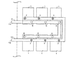
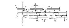
このようなパイプユニット1を、図5、図6に示すように、天井裏に複数設置して冷暖房システムとすることがある。なお、図5は、天井裏に設置したパイプユニット1を上から見た図であり、図6は、天井裏を側面から見た図である。そして、図6では、パイプユニット1が設置されている室内と廊下などとの境界を一点鎖線で示し、個々のパイプユニットは省略し、全体を二点鎖線で表示している。
図5,図6に示すように、各パイプユニット1の供給口6を、それぞれ、接続パイプ13と継ぎ手14を介して供給流路9に接続し、各戻り口7を、接続パイプ15と継ぎ手14とを介して戻り流路10に接続している。そして、上記供給流路9の供給口11と戻り流路10の戻り口12とを天井裏から外に出し、供給口11を、図示しない流体循環装置のポンプ吐出側に接続し、戻り口12をタンク側に接続している。
【0006】
このように、各パイプユニット1を、供給流路9や戻り流路10に並列に接続しているのは、各パイプユニット1に供給される流体温度が、均一になるようにするためである。例えば、複数のパイプユニットを直列に接続した場合には、ポンプの吐出側から離れるに従って、パイプユニット1に供給される流体の温度が、徐々に下がってしまう。
【0007】
また、図5では、各パイプユニット1の供給口6と戻り口7の位置がわかり易いように、供給口6を白丸、戻り口7を黒丸で表している。実際は、供給口6と戻り口7の上方には、供給流路9および戻り流路10があるので、供給口6および戻り口7は、上からは見えない。そして、供給口11,戻り口12は、廊下の天井裏など、流体循環装置との接続が容易にできるスペースに開口させている。なお、図5,図6のような配管は、実際に行われているが、このような配管についての文献調査は行っていない。そのため、本願発明に係わる先行技術文献は知らない。
【0008】
【発明が解決しようとする課題】
上記のように、パイプユニット1を天井裏に敷設する際には、パイプユニット1の供給口6と供給流路9との接続作業と、戻り口7と戻り流路10との接続作業とを行わなければならない。実際に、多数の接続パイプ13を供給口6や継ぎ手14に溶着やネジによって取り付け、さらに、多数の接続パイプ15を戻り口7や継ぎ手14によう着やネジによって取り付け、その後、上記継ぎ手14に、供給流路9と戻り流路10を接続する作業は、手間が掛かって大変である。特に、天井裏のような狭い作業スペースで行う配管作業は、非常に困難で、手間も時間も掛かってしまう。しかも、接続パイプ13,15や継ぎ手14などの接続個所が多いため、その接続個所から流体が漏れる可能性も高い。
【0009】
したがって、確実な接続を行うためには、配管作業になれた作業員でも、非常に時間が掛かるという問題があった。また、実際に使用を開始してから、継ぎ目から流体の漏れが発生した場合には、再度、天井裏での作業を行わなければならない。
この発明の目的は、冷暖房用のパイプユニットの敷設の作業を簡単にして、敷設作業性の良い冷暖房システムを提供することである。
【0010】
【課題を解決するための手段】
第1の発明は、流体を供給するための供給口と、流体を戻すための戻り口とを備えた複数の冷暖房用パイプユニットと、上記供給口に流体を供給するとともに、戻り口からの流体を受ける機能を有する循環機構と、この循環機構と接続した分岐装置と、この分岐装置と上記供給口とを接続する可撓性を有する可撓性供給パイプと、上記分岐装置と上記戻り口とを接続する可撓性を有する可撓性戻りパイプとを備えている。そして、各パイプユニットに予め結合した可撓性供給パイプの長さを等しくし、各パイプユニットに予め結合した可撓性戻りパイプの長さを等しくした点に特徴を有する。
【0011】
第2の発明は、分岐装置と、可撓性供給パイプおよび可撓性戻りパイプとをプラグとソケットからなる継ぎ手を介して接続し、上記パイプ側には、継ぎ手のプラグを設け、上記分岐装置側には、その内部にシール部材を備えた継ぎ手のソケットを設けた点に特徴を有する。
【0012】
【発明の実施の形態】
図1〜図3に、この発明の実施例の冷暖房システムを示す。
なお、この実施例の冷暖房システムに用いる冷暖房用のパイプユニットは、従来例のものと同じなので、図4のパイプユニット1を用いるものとする。
ただし、この実施例のパイプユニット1では、図1に示すように、供給側メインパイプ2の供給口6に可撓性を有する可撓性供給パイプ16を接合し、戻り側メインパイプ3の戻り口7には、やはり、可撓性を有する可撓性戻りパイプ17を接合している。これらの可撓性パイプ16,17は、それぞれ供給口6と戻り口7に予め固定しておいて施工現場に持ち込むようにするので、施工現場で、パイプの接続作業を行う必要がなく楽である。
【0013】
さらに、全ての供給口6に接合された可撓性供給パイプ16は、長さを等しくしている。また、全ての戻り口7に接合された可撓性戻りパイプ17も、長さを等しくしている。これらの長さは、後で説明する分岐装置19、20から最も遠いパイプユニット1の供給口6や戻り口7までの距離と、ほぼ同等かそれよりも若干長くしている。
また、各可撓性供給パイプ16と、可撓性戻りパイプ17の端部には、継ぎ手のプラグ18を接続している。この継ぎ手は、後で説明する分岐装置19、20と可撓性供給パイプ16や可撓性戻りパイプ17とを接続するための継ぎ手である。
【0014】
上記分岐装置19は、パイプユニット1の可撓性供給パイプ16をまとめて、この発明の循環機構である流体循環装置21に接続する装置であり、分岐装置20は、パイプユニット1の可撓性戻りパイプ17をまとめて上記循環装置21に接続する装置である。流体循環装置21は、この分岐装置19を介して各可撓性供給パイプ16から各パイプユニット1へ流体を供給し、パイプユニット1から可撓性戻りパイプ17を介して戻される流体を受ける機能を備えている。
この実施例では、流体循環装置21が、流体を供給する機能と戻り流体を受ける機能とを1つの装置内に備えている。また、この流体循環装置21には、流体を冷却または加熱する機構も備えていえる。
ただし、この発明の循環機構は、例えば、流体を受けるタンクと、このタンクと離れた場所に設置され、流体を供給するポンプとで構成するものでもかまわない。
【0015】
また、分岐装置19には、図3に示すように、上記プラグ18とともに継ぎ手を構成するソケット22が取り付けられている。つまり、上記プラグ18をソケット22に押し込むと、両者は接続され、ソケット22内のストッパ機構によってプラグ18がはずれなくなる。ただし、ソケット22の図示しない解放リングをプラグ18と反対方向にずらすと、上記ストッパ機構が解除されて、プラグ18を引き抜くことができるようにしている。
一方、分岐装置20にも、分岐装置19と同様に、ソケット22が取り付けられていて、そこに、可撓性戻りパイプ17のプラグ18を接続するようにしている。
【0016】
上記のように、可撓性供給パイプ16と、可撓性戻りパイプ17とを備えたパイプユニット1を複数、天井裏に設置した状態を図2に示す。この図2では、各パイプユニット1の供給口6を白丸で表し、戻り口7を黒丸で表している。また、一点鎖線Lは、天井裏とメンテナンススペースSとの境界である。
上記メンテナンススペースSとは、上記分岐装置19,20を設置するスペースで、例えば廊下の天井裏など、パイプの接続作業や、各装置のメンテナンスがやりやすいスペースである。
【0017】
なお、上記メンテナンススペースSは、廊下など室外に設けなければならないものではなく、パイプユニット1を設置した天井裏の一部に上記分岐装置19,20を設置して、メンテナンススペースとすることもできる。ただし、その場合には、室内から、パイプの接続状況を確認したり、分岐装置19,20のメンテナンスができるように、点検口などを設ける必要がある。あるいは、室内や、廊下の壁際などに、上記分岐装置19,20を設置するスペースを設けても良い。また、図2に示すこの実施例では、上記分岐装置19,20とともに流体循環装置21も、廊下側のメンテナンススペースSに、設置しているが、上記流体循環装置21は、地下や、屋外など、どこに設置してもかまわない。
【0018】
このような冷暖房システムを設置する手順を以下に説明する。
まず、天井裏に必要な数のパイプユニット1を敷設する。そして、各パイプユニット1に接合されている可撓性供給パイプ16と、可撓性戻りパイプ17とを廊下側のメンテナンススペースSへ引き出す。
次に、メンテナンススペースSに設置した分岐装置19のソケット22に、可撓性供給パイプ16の各プラグ18を接続し、分岐装置20のソケット22に、可撓性戻りパイプ17のプラグ18を接続する。
【0019】
全ての可撓性供給パイプ16を分岐装置19に接続し、全ての可撓性戻りパイプ17を分岐装置20に接続したら、各分岐装置19,20を流体供給装置21に接続する。以上で、冷暖房システムの完成である。
なお、上記可撓性供給パイプ16は、全て長さが等しく、また、可撓性戻りパイプ17も、全て長さが等しいので、流体供給装置21から各パイプユニット1までのそれぞれの流路抵抗が等しくなる。そのため、流体循環装置21から各パイプユニット1に供給される流体の流量や流速にばらつきが無く、同じ温度の流体が供給されることになる。
【0020】
また、全ての可撓性供給パイプ16が等しいので、分岐装置19までの距離が短いパイプユニット1の可撓性供給パイプ16は長さが余ってしまうが、その分は、天井裏やメンテナンススペースS内で、巻くなどして余らせておけばよい。
可撓性戻りパイプ17に関しても同様である。
以上のように、この発明のシステムでは、従来のように、パイプユニットの敷設時に、面倒な配管作業が不要になる。従って、作業性が向上し、作業時間も短縮できる。さらに、接続個所から、流体が漏れる心配もない。
【0021】
また、上記実施例では、分岐装置19,20側に継ぎ手のソケット22を設け、可撓性供給パイプ16と可撓性戻りパイプ17側にプラグ18を設けている。通常、シール部材は、ソケット22内に設けているので、長期の使用でシール部材が破損したり、劣化したりした場合に、分岐装置19、20側を取り替えれば良い。
もしも、可撓性供給パイプ16や可撓性戻りパイプ17に、プラグ18の代わりにソケット22を設けた場合に、その中に設けたシール部材が破損したときには、可撓性パイプ16,17を予め結合したパイプユニット1までも取り替えなければならないが、この実施例ではその必要がない。
【0022】
なお、プラグの外周にシール部材を取り付けた場合には、シール部材の交換が簡単であるが、シール部材が脱落したり、傷ついたりし易いので、あまり好ましくない。ただし、その場合には、分岐装置19,20側に、ソケット22とプラグ18のどちらを設けてもシールの破損に対応できる。
また、この実施例では、図4に示すパイプユニット1を用いたが、パイプユニットはこれに限らない。例えば、供給側メインパイプ2と戻り側メインパイプ3とが平行位置に対向しているものや、両メインパイプ2,3が同軸上に接続されているものでもかまわないし、その他、どのような形状でもかまわない。さらに、上記のようなメインパイプ2、3と熱交換パイプ5とを、断熱材などとともに、一体化してパネル状にしたパイプユニットを用いることもできる。
【0023】
さらに、上記実施例では、パイプユニット1を天井裏に設置する例を説明したが、パネル化したパイプユニットを天井材として設置するようにしても良い。
もちろん、天井だけでなく、壁や床などに設置して冷暖房をすることもできる。どこに用いるにしても、作業性がよく、簡単に施工できるメリットは同様である。
【0024】
【発明の効果】
第1、第2の発明によれば、パイプユニットの施工時に、複雑な配管作業を必要としない。従って、作業性がよく、配管の技術がない者でも、短時間で、施工作業ができる。
第2の発明によれば、パイプユニットを設置後、分岐装置と可撓性パイプとの間の継ぎ手のシール部材が破損した場合に、容易に対応できるようになる。
【図面の簡単な説明】
【図1】この発明の実施例のパイプユニットの正面図である。
【図2】実施例の冷暖房システムのパイプユニットを天井に設置した状態を示した図である。
【図3】実施例の分岐装置と、可撓性供給パイプとの接続部を示した図である。
【図4】従来例のパイプユニットの平面図である。
【図5】従来例の冷暖房システムのパイプユニットを天井に設置した状態を上から見た図である。
【図6】従来例の冷暖房システムのパイプユニットを天井に設置した状態を側面から見た図である。
【符号の説明】
1 パイプユニット
2 供給側メインパイプ
3 戻り側メインパイプ
6 供給口
7 戻り口
16 可撓性供給パイプ
17 可撓性戻りパイプ
18 プラグ
19 分岐装置
20 分岐装置
21 流体循環装置
22 ソケット[0001]
TECHNICAL FIELD OF THE INVENTION
The present invention relates to a cooling and heating system in which a pipe unit for flowing a fluid for heat exchange is installed on a ceiling or a wall.
[0002]
[Prior art]
The
The supply side
[0003]
On the other hand, the return side
Therefore, the fluid supplied from the supply side
[0004]
Since the
[0005]
As shown in FIGS. 5 and 6, a plurality of
As shown in FIGS. 5 and 6, the
[0006]
The reason why each
[0007]
In FIG. 5, the
[0008]
[Problems to be solved by the invention]
As described above, when laying the
[0009]
Therefore, there is a problem that it takes a very long time even for an operator who has become a plumbing worker to perform a reliable connection. Further, if fluid leakage occurs from the seam after actually starting use, it is necessary to perform work again above the ceiling.
An object of the present invention is to provide a cooling and heating system which simplifies the work of laying a pipe unit for cooling and heating and has good laying workability.
[0010]
[Means for Solving the Problems]
A first invention provides a plurality of cooling / heating pipe units each having a supply port for supplying a fluid, and a return port for returning the fluid, and supplying a fluid to the supply port and a fluid from the return port. Circulating mechanism having a function of receiving the circulating mechanism, a branching device connected to the circulating mechanism, a flexible supply pipe connecting the branching device and the supply port, a flexible supply pipe, the branching device and the return port, And a flexible return pipe having flexibility. The present invention is characterized in that the length of the flexible supply pipe previously connected to each pipe unit is made equal, and the length of the flexible return pipe previously connected to each pipe unit is made equal.
[0011]
According to a second aspect of the present invention, the branching device is connected to a flexible supply pipe and a flexible return pipe via a joint consisting of a plug and a socket. On the side, there is a feature that a socket of a joint provided with a seal member therein is provided.
[0012]
BEST MODE FOR CARRYING OUT THE INVENTION
1 to 3 show a cooling and heating system according to an embodiment of the present invention.
The pipe unit for cooling and heating used in the cooling and heating system of this embodiment is the same as that of the conventional example, so the
However, in the
[0013]
Further, the
A
[0014]
The branching
In this embodiment, the
However, the circulation mechanism of the present invention may be configured by, for example, a tank that receives a fluid, and a pump that is provided at a location separated from the tank and supplies the fluid.
[0015]
As shown in FIG. 3, a
On the other hand, similarly to the branching
[0016]
FIG. 2 shows a state in which a plurality of
The maintenance space S is a space where the branching
[0017]
Note that the maintenance space S does not have to be provided outside a room such as a corridor, and the branching
[0018]
The procedure for installing such a cooling and heating system will be described below.
First, a required number of
Next, each plug 18 of the
[0019]
When all the
Since the
[0020]
In addition, since all the
The same applies to the
As described above, the system of the present invention eliminates the need for complicated piping work when laying a pipe unit as in the related art. Therefore, workability is improved and work time can be reduced. Furthermore, there is no fear that fluid leaks from the connection point.
[0021]
Further, in the above embodiment, the
If a
[0022]
When the seal member is attached to the outer periphery of the plug, the replacement of the seal member is easy, but it is not preferable because the seal member is easily dropped or damaged. However, in that case, the breakage of the seal can be dealt with by providing either the
In this embodiment, the
[0023]
Further, in the above-described embodiment, an example in which the
Of course, it can be installed on the wall, floor, etc., as well as on the ceiling, for cooling and heating. Regardless of where it is used, the workability is good and the merit of easy construction is the same.
[0024]
【The invention's effect】
According to the first and second aspects of the present invention, complicated piping work is not required at the time of installing the pipe unit. Accordingly, the workability is good, and even a person who does not have the skill in piping can perform the construction work in a short time.
According to the second aspect, it is possible to easily cope with a case where the seal member of the joint between the branching device and the flexible pipe is broken after the pipe unit is installed.
[Brief description of the drawings]
FIG. 1 is a front view of a pipe unit according to an embodiment of the present invention.
FIG. 2 is a diagram illustrating a state where a pipe unit of the cooling and heating system according to the embodiment is installed on a ceiling.
FIG. 3 is a diagram showing a connection portion between the branching device of the embodiment and a flexible supply pipe.
FIG. 4 is a plan view of a conventional pipe unit.
FIG. 5 is a top view of a state in which a pipe unit of a conventional cooling and heating system is installed on a ceiling.
FIG. 6 is a side view showing a state in which a pipe unit of a conventional cooling and heating system is installed on a ceiling.
[Explanation of symbols]
DESCRIPTION OF
Claims (2)
Priority Applications (1)
| Application Number | Priority Date | Filing Date | Title |
|---|---|---|---|
| JP2002302515A JP2004138135A (en) | 2002-10-17 | 2002-10-17 | Air-conditioning system |
Applications Claiming Priority (1)
| Application Number | Priority Date | Filing Date | Title |
|---|---|---|---|
| JP2002302515A JP2004138135A (en) | 2002-10-17 | 2002-10-17 | Air-conditioning system |
Publications (1)
| Publication Number | Publication Date |
|---|---|
| JP2004138135A true JP2004138135A (en) | 2004-05-13 |
Family
ID=32450559
Family Applications (1)
| Application Number | Title | Priority Date | Filing Date |
|---|---|---|---|
| JP2002302515A Pending JP2004138135A (en) | 2002-10-17 | 2002-10-17 | Air-conditioning system |
Country Status (1)
| Country | Link |
|---|---|
| JP (1) | JP2004138135A (en) |
-
2002
- 2002-10-17 JP JP2002302515A patent/JP2004138135A/en active Pending
Similar Documents
| Publication | Publication Date | Title |
|---|---|---|
| CN104155704B (en) | Sensor probe | |
| KR100782676B1 (en) | Wall embedded faucet connection system | |
| JP2004138135A (en) | Air-conditioning system | |
| JP2017525934A (en) | Heat exchanger and air conditioner provided with the same | |
| US7558457B2 (en) | Combined illumination and ventilation duct | |
| ATE325989T1 (en) | DISTANCE HEATING, HOUSE CONNECTION THEREOF, CONTROL FOR THIS HOUSE CONNECTION AND METHOD FOR OPERATING THIS DISTANCE HEATING SYSTEM | |
| US6862918B2 (en) | Device for testing domestic water piping systems and methodology | |
| US20160327308A1 (en) | Plug and play modular comfort device and interface template adapted to said plug and play modular comfort device | |
| CN106122610A (en) | A kind of guiding corrugated bushing for pre-buried water supply pipe system | |
| JP5887484B2 (en) | Heat pump water heater | |
| JP2006029639A (en) | Air conditioning system | |
| US20040104281A1 (en) | Fitting-assembly and fitting-block for a central heating system | |
| KR20090009534U (en) | Dispenser Box for Air Conditioner for Easy Landfilling | |
| KR200321663Y1 (en) | Heating Pipet Having Multi Output Line | |
| JP2775025B2 (en) | Water leak prevention cold and hot water piping system | |
| JP6798685B2 (en) | Hot water supply piping system | |
| SK97895A3 (en) | Connecting system for radiators | |
| CN101258367A (en) | Air distribution system for air conditioning system | |
| CN216643328U (en) | High-temperature-resistant pp air pipe | |
| WO2019142575A1 (en) | Branch unit, refrigeration device, and method for installing refrigeration device | |
| AU2003213465B2 (en) | Combined hot-water supply system | |
| JP2011030681A (en) | Sprinkler system of direct water service connection type | |
| RU2792184C2 (en) | Pipe shaft module | |
| JP2892946B2 (en) | Centralized piping structure | |
| JP2004218224A (en) | Water distribution board |
Legal Events
| Date | Code | Title | Description |
|---|---|---|---|
| A621 | Written request for application examination |
Effective date: 20051017 Free format text: JAPANESE INTERMEDIATE CODE: A621 |
|
| A131 | Notification of reasons for refusal |
Effective date: 20080916 Free format text: JAPANESE INTERMEDIATE CODE: A131 |
|
| A521 | Written amendment |
Effective date: 20081114 Free format text: JAPANESE INTERMEDIATE CODE: A523 |
|
| A02 | Decision of refusal |
Free format text: JAPANESE INTERMEDIATE CODE: A02 Effective date: 20090331 |