JP2004056779A - Image inputting device - Google Patents
Image inputting device Download PDFInfo
- Publication number
- JP2004056779A JP2004056779A JP2003154814A JP2003154814A JP2004056779A JP 2004056779 A JP2004056779 A JP 2004056779A JP 2003154814 A JP2003154814 A JP 2003154814A JP 2003154814 A JP2003154814 A JP 2003154814A JP 2004056779 A JP2004056779 A JP 2004056779A
- Authority
- JP
- Japan
- Prior art keywords
- image
- camera
- mirror
- partial
- unit
- Prior art date
- Legal status (The legal status is an assumption and is not a legal conclusion. Google has not performed a legal analysis and makes no representation as to the accuracy of the status listed.)
- Granted
Links
Images


Landscapes
- Image Processing (AREA)
- Closed-Circuit Television Systems (AREA)
- Editing Of Facsimile Originals (AREA)
- Studio Devices (AREA)
- Image Input (AREA)
Abstract
Description
【0001】
【発明の属する技術分野】
本発明は広範囲の画像を複数の画像を合成することで取得する画像入力装置に関するものである。
【0002】
【従来の技術】
通常用いられるビデオカメラ等の画像入力機器は、限られた視野を持つため、ユーザを取り囲む外界の情報の内、極一部のみを映し出していると考えられる。このような限られた視野を拡大し、広視野画像を取得可能な画像入力装置を用いると、例えば、店舗内や屋外の監視においては、従来は監視者が注視する近辺の映像しか得られなかったのに対し、周囲の状況も含めて一目で確認できるため視認性が著しく向上すると考えられる。また、広視野画像入力機器であれば一台で監視する範囲も広くなり全体としてのコストダウンにもつながると期待される。
【0003】
旧来の広視野画像取得方法は円柱の側面に貼り付けられたフィルム上を、反対側の側面を移動するスリットから投影される光が走査する形態(いわゆるパノラマカメラ)や魚眼レンズ/広角レンズを用いて直接広視野画像を取得する形態が主であった。広視野画像はそのままパノラマ写真として用いるか、魚眼レンズ等の場合は逆変換を適用する光学系を通じてスクリーンに投射するのが主な目的であり、計算機において広視野画像を利用するためにはフィルムや写真をスキャナ等により入力するという手間を必要とした。
【0004】
ハードウェアの進展により画像を直接計算機に入力可能となるに従い、計算機上に入力された画像に幾何変換や合成処理を適用することで広視野画像を得る形態が利用されるようになった。この計算機上における処理を前提とした広視野画像取得手法は、通常のカメラで撮った部分画像を合成して広視野画像を生成する画像合成型と、広角レンズまたはミラーを用いて直接広視野画像を取得する光学型に、大きく分類できる。
【0005】
画像合成型はさらに、カメラが回転するように調整された三脚/雲台を用いて複数の部分画像を取得し、それらを合成して広視野画像を生成する手法、複数のカメラを用いて得た部分画像を合成する手法、に分類できる。前者では、通常のカメラで取得した複数の画像を合成するため、得られた広視野画像は高い解像度を持つが、従来の手法では視点移動に伴い画像間に発生する視差の問題を回避するために、レンズの主点を中心にカメラが回転するように構成された機構を必要とする(例えば、特許文献1、2参照。)。また、部分画像取得作業が煩雑であり、カメラの重量・サイズが大きく、信号・電源ケーブルの特性上カメラを継続的かつ高速に回転させられないため広視野画像を連続して取得するのが困難であるという問題があった。
【0006】
後者は、カメラを固定的に配置するため一度正しい設定が得られれば画像取得そのものには時間を必要とせずリアルタイム性が高い反面、多数のカメラを配置するため装置サイズが大きくなり、また、カメラが固定されているため解像度や撮像範囲を変更するのが困難であるという問題がある。さらには、用いるカメラの数が増加した場合には各カメラの映像を計算機に入力する機構も大掛かりなものとなる。
【0007】
光学型は広角レンズ/ミラーを用いて広視野画像を直接取得し、幾何変換により画像を再構成するものである。魚眼レンズを用いたもの、ミラーを用いたもの等が開発されている。いずれの手法においても、一度の撮像で広視野画像を取得できるためレンズ/ミラーは固定であり、かつ、リアルタイム性が高いが、得られた広視野画像の解像度が低いという問題がある。特に魚眼レンズを用いる手法では画像端部の歪みが大きく、幾何変換を適用しても非常に粗い画像しか得られない。ミラーを用いた広視野画像入力機器と注視点画像を取得するカメラを組み合わせた手法も存在するが、注視点画像の解像度は高いものの、広視野画像そのものの解像度不足を解決するには至っていない。従来の広視野画像入力手法の問題点を解決し、解像度が高く、継続的かつ高速に広視野画像を取得可能な手法として、カメラ前面でミラーを回転させて取得した複数の部分画像を合成する手法がある。画像と実際の上下左右の対応が変化することや幾何的な歪みを除けば、ミラーをカメラの光軸周りに回転させることはカメラのパン操作に、また、ミラーをカメラ光軸に垂直な軸周りに回転させることはカメラのチルト操作に相当することから、このミラーの回転を用いて複数の部分画像を取得し、得られた部分画像に幾何変換を適用して合成し、広視野画像を取得するものである。
【0008】
【特許文献1】
特開平9−18750号公報
【特許文献2】
特開平8−116490号公報
【0009】
【発明が解決しようとする課題】
しかしながら、先にあげた特開平9−18750号公報に係る明細書にて指摘されているように、従来のミラーを回転させて取得した部分画像を合成することにより広視野画像を入力する画像入力装置には、
1. 撮影範囲を切り替えるためのミラーが大きくなる、
2. レンズ前面に配置されたミラーによって撮影範囲を切り替えると視差が生じるという問題があった。特に後者は、レンズ主点以外にてカメラを回転させた場合にも発生する問題であり、合成画像における連続性を損ない、広視野画像の画質を著しく低下させてしまうという問題が有った。
【0010】
本発明は、このような事情に鑑みてなされたものであり、本発明は、ミラーをカメラ前面にて回転することにより取得した複数の部分画像を合成する際に、高速に広視野画像を入力することができる画像入力装置を提供することを目的とする。
【0011】
【課題を解決するための手段】
上記目的を達成するために請求項1に記載の発明は、被写界を撮像するカメラと、被写界からの反射光を前記カメラのカメラレンズ方向に光路変換するために前記カメラの前方に配置されたミラーと、前記ミラーを前記カメラの光軸回りに回転させるミラー回転機構と、前記ミラーの回転に伴って前記カメラより入力される複数の画像を合成して広視野角の画像を生成する処理手段とを有する画像入力装置であって、前記ミラーは、側面のうち2面が反射面となっている三角柱ミラーであり、前記カメラは、前記ミラーの2面の前記反射面で光路変換された被写体からの反射光を撮像し、前記処理手段は、前記カメラにより撮像された複数の各画像を前記ミラーの反射面に対応させて分離して独立に画像合成することを特徴とする。
【0012】
また請求項2に記載の発明は、請求項1に記載の画像入力装置において、前記処理手段は、前記カメラにより撮像された画像を取得し、ディジタル処理する画像取得手段と、前記画像取得手段により取得されディジタル処理された各画像を前記ミラーの2つの反射面に対応させて分離する画像分離手段と、前記ミラーの2つの反射面のうち第1の反射面に対応して前記画像分離手段により分離された画像を合成する第1の画像合成手段と、前記ミラーの2つの反射面のうち第2の反射面に対応して前記画像分離手段により分離された画像を合成する第2の画像合成手段と、前記第1、第2の画像合成手段により合成された画像を広視野画像の上から重ね書きすることにより更新する画像更新手段とを有することを特徴とする。
【0013】
請求項1、2に記載の発明によれば、被写界を撮像するカメラと、被写界からの反射光を前記カメラのカメラレンズ方向に光路変換するために前記カメラの前方に配置されたミラーと、前記ミラーを前記カメラの光軸回りに回転させるミラー回転機構と、前記ミラーの回転に伴って前記カメラより入力される複数の画像を合成して広視野角の画像を生成する処理手段とを有する画像入力装置であって、前記ミラーは、側面のうち2面が反射面となっている三角柱ミラーであり、前記カメラは、前記ミラーの2面の前記反射面で光路変換された被写体からの反射光を撮像し、前記処理手段は、前記カメラにより撮像された複数の各画像を前記ミラーの反射面に対応させて分離して独立に画像合成するようにしたので、2方向の画像を同時に撮像、合成及び更新することができ、それ故、ミラーをカメラ前面にて回転することにより取得した複数の部分画像を合成する際に、広視野画像を高速に入力することが可能となる。
【0014】
また請求項3に記載の発明は、カメラレンズの光軸を一致させて互いに向き合うように配置され被写界を撮像する第1、第2の2台のカメラと、前記第1、第2のカメラの間に配置され、被写界からの反射光を前記第1、第2のカメラのカメラレンズ方向に光路変換する両面ミラーと、前記両面ミラーを前記第1、第2のカメラの光軸回りに回転させるミラー回転機構と、前記記ミラーの回転に伴って前記第1、第2のカメラより入力される複数の画像を合成して広視野角の画像を生成する処理手段とを有することを特徴とする。
【0015】
また請求項4に記載の発明は、請求項3に記載の画像入力装置において、前記処理手段は、前記両面ミラーの第1の反射面からの反射光を撮像する前記第1のカメラにより撮像された画像を取得し、ディジタル処理する第1の画像取得手段と、前記両面ミラーの第2の反射面からの反射光を撮像する前記第2のカメラにより撮像された画像を取得し、ディジタル処理する第2の画像取得手段と、前記第1の画像取得手段によりディジタル処理された画像を合成する第1の画像合成手段と、前記第2の画像取得手段によりディジタル処理された画像を合成する第2の画像合成手段と、前記第1、第2の画像合成手段により合成された画像を広視野画像の上から重ね書きすることにより更新する画像更新手段と、を有することを特徴とする。
【0016】
請求項3、4に記載の発明によれば、カメラレンズの光軸を一致させて互いに向き合うように配置され被写界を撮像する第1、第2の2台のカメラと、前記第1、第2のカメラの間に配置され、被写界からの反射光を前記第1、第2のカメラのカメラレンズ方向に光路変換する両面ミラーと、前記両面ミラーを前記第1、第2のカメラの光軸回りに回転させるミラー回転機構と、前記記ミラーの回転に伴って前記第1、第2のカメラより入力される複数の画像を合成して広視野角の画像を生成する処理手段とを有するので、ミラーをカメラ前面にて回転することにより取得した複数の部分画像を合成する際に、高速に広視野画像を入力することができると共に、請求項29、30に記載の発明に係る画像入力装置により得られる広視野画像より高い解像度の広視野画像を生成することができる。
【0017】
【発明の実施の形態】
以下、本発明の実施の形態について図面を参照して詳細に説明する。
図1は、本発明の第1の実施の形態を説明するための図である。
図1において、本発明における画像入力装置100は、カメラ005の撮影方向、すなわち向きを変更するためのカメラ移動手段014と、カメラ移動手段014に対してカメラ005の向きを変更するよう指示を出すと共にカメラ005の姿勢情報を各部に伝える姿勢制御手段015と、外界の画像を取得するカメラ005と、カメラ005の映し出した画像を装置内に取り込む撮像手段006と、撮像手段006を制御して部分画像を画像メモリ008に格納し、かつ、部分画像取得時のカメラ005の向きおよび部分画像と合成画像の属性情報を画像属性メモリ004に格納する撮像制御手段007と、撮像制御手段007が格納した部分画像および、得られた部分画像を合成して作成した合成画像を格納する画像メモリ008と、部分画像の属性情報、部分画像の取得時のカメラ005の向きの情報を格納する画像属性メモリ004と、部分画像に含まれる視差の影響を、カメラの回転中心を投影の中心とし、かつ、各部分画像上の画素に対応する空間上の直線の無限遠点を用いて投影点を決定することにより低減しながら、画像属性メモリ004および画像メモリ008を参照して各部分画像を合成して、合成画像を画像メモリ008に格納する画像合成手段009と、から構成される。尚、撮像手段006及び撮像制御手段007は本発明の部分画像取得手段に、画像メモリ008は本発明の第1の記憶手段に、画像属性メモリ004は本発明の第2の記憶手段に、それぞれ相当する。
【0018】
本発明における画像入力装置100の第1の実施の形態の動作の概略は以下の通りである。
カメラ005はカメラ移動手段014により向きが変更可能となっている。カメラ移動手段014は姿勢制御手段015の指示に応じてカメラ005の向きを変更する。
カメラ005は外界の様子を撮像可能であり、カメラ005が映し出す範囲はその向きに応じて変化する。
姿勢制御手段015は、カメラ移動手段014にカメラ005の向きを変更するように指示を出し、カメラ移動手段014は姿勢制御手段015の指示を受け、カメラ005の向きを移動させる。
【0019】
次に、撮像制御手段007は、撮像手段006に部分画像を取得するように指示を出す。
また撮像手段006は、撮像制御手段007から指示を受け取ると、姿勢制御手段015の指示により向きを変えたカメラ005により部分画像を撮影し装置内に取り込む。
撮像制御手段007は、撮像手段006が取り込んだ画像を画像メモリ008に、画像取得時のカメラ005の向きの情報を画像属性メモリ004に、それぞれ格納する。
【0020】
画像合成手段009は、撮像制御手段007により画像属性メモリ004に格納された部分画像を取得した時のカメラ005の姿勢情報を用いて部分画像の合成位置を求める。求めた合成位置に従って、画像メモリ008に格納された部分画像を、カメラの回転中心を投影の中心とし、かつ、各部分画像上の画素に対応する空間上の直線の無限遠点を用いて投影点を決定することにより、すなわちカメラの回転中心を投影の中心とし、前記カメラの視点と前記複数の各部分画像が形成される画像平面上における部分画像上の画素とを結ぶ直線に平行で、かつ前記カメラの回転中心を通る直線と空間上に設定された投影面との交点を前記部分画像上の画素の投影点とすることにより、部分画像間に含まれる視差の影響を低減しながら画像メモリ008に格納されている合成画像上に合成して、合成画像を更新する。
【0021】
上記の各処理を繰り返すことで、本発明における画像入力装置100は、広視野の合成画像を取得できる。
本画像入力装置100により得られた部分画像や合成画像は、例えば、表示制御手段011により選択された後、表示手段012に表示され、ユーザに提示される。
次に、本発明の第2の実施の形態について図面を参照して詳細に説明する。
図2は、本発明の第2の実施の形態の構成を説明するための図である。
第1の実施の形態と同じ名称を持つ構成要素は基本的に同じ機能を提供する。以下では、第1の実施の形態との差異について説明する。
【0022】
第2の実施の形態は、第1の実施の形態に対して、画像メモリ008内の部分画像間に位置合わせ処理を適用して部分画像間の位置関係を求め、その結果に基づいて、画像属性メモリ004に格納されている各部分画像の取得位置の位置補正量を求めて、画像属性メモリ004に格納する位置合わせ手段013が追加されている。
【0023】
また、第2の実施の形態における各構成要素の内、画像属性メモリ004は、カメラ005および撮像手段006を用いて撮像制御手段007が取得した部分画像の取得時のカメラ005の向きの情報と、部分画像と合成画像に関連する属性情報、および位置合わせ手段013により求められた各部分画像の合成位置の位置補正量、をそれぞれ格納する様に、また、画像合成手段009は、撮像制御手段007により画像属性メモリ004に格納された部分画像を取得した時のカメラ005の向き情報と、位置合わせ手段013により求めた合成位置の位置補正量とを用いて部分画像の合成位置を求め、求めた合成位置に従って、画像メモリ008に格納された部分画像を、カメラの回転中心を投影の中心とし、かつ、各部分画像上の画素に対応する空間上の直線の無限遠点を用いて投影点を決定することにより、すなわちカメラの回転中心を投影の中心とし、前記カメラの視点と前記複数の各部分画像が形成される画像平面上における部分画像上の画素とを結ぶ直線に平行で、かつ前記カメラの回転中心を通る直線と空間上に設定された投影面との交点を前記部分画像上の画素の投影点とすることにより、部分画像間に含まれる視差の影響を低減しながら、画像メモリ008に格納されている合成画像上に合成して、合成画像を更新する様に、それぞれ変更されている。
【0024】
第2の実施の形態の動作の概略について説明する。
カメラ005はカメラ移動手段014により向きを変更可能となっている。カメラ移動手段014は姿勢制御手段015の指示に応じてカメラ005の向きを変更する。
カメラ005は外界の様子を撮像可能であり、カメラ005が映し出す範囲はその向きに応じて変化する。
姿勢制御手段015は、カメラ移動手段014にカメラ005の向きを変更するように指示を出し、カメラ移動手段014は姿勢制御手段015の指示を受け、カメラ005の向きを移動する。
【0025】
次に、撮像制御手段007は、撮像手段006に部分画像を取得するように指示を出す。
次に、撮像手段006は、撮像制御手段007から指示を受け取ると、姿勢制御手段015の指示により向きを変えたカメラ005により部分画像を撮影し装置内に取り込む。
撮像制御手段007は、撮像手段006が取り込んだ部分画像を画像メモリ008に、画像取得時のカメラ005の向きの情報を画像属性メモリ004に、それぞれ格納する。
位置合わせ手段013は、画像メモリ008内の部分画像間に位置合わせ処理を適用して部分画像間の位置関係を求め、その結果に基づいて、画像属性メモリ004内の各部分画像の位置補正量を求めて、画像属性メモリ004に格納する。
【0026】
画像合成手段009は、撮像制御手段007により画像属性メモリ004に格納された部分画像を取得した時のカメラ005の向き情報と、位置合わせ手段013により求めた位置補正量とを用いて部分画像の合成位置を求め、求めた合成位置に従って、画像メモリ008に格納された部分画像を、部分画像に含まれる視差の影響を、カメラの回転中心を投影の中心とし、かつ、各部分画像上の画素に対応する空間上の直線の無限遠点を用いて投影点を決定することにより、すなわちカメラの回転中心を投影の中心とし、前記カメラの視点と前記複数の各部分画像が形成される画像平面上における部分画像上の画素とを結ぶ直線に平行で、かつ前記カメラの回転中心を通る直線と空間上に設定された投影面との交点を前記部分画像上の画素の投影点とすることにより、低減しながら、同じく画像メモリ008に格納されている合成画像上に合成して合成画像を更新する。
【0027】
上記の各処理を繰り返すことで、本発明における画像入力装置100は、広視野の合成画像を取得できる。
本画像入力装置100により得られた部分画像や合成画像は、例えば、表示制御手段011により選択された後、表示手段012に表示され、ユーザに提示される。
図3は、本発明の第3の実施の形態を説明するための図である。
第1および第2の実施の形態と同じ名称を持つ構成要素は基本的に同じ機能を提供する。以下では、第1の実施の形態との差異について説明する。
【0028】
第3の実施の形態は、第1の実施の形態に対して、カメラ移動手段014と姿勢制御手段015を削除し、カメラ005のレンズ前に保持され、ミラー移動手段002により向きを変更可能なミラー001と、ミラー001の向きを変更するためのミラー移動手段002と、ミラー移動手段002に対してミラー001の向きを変更するよう指示を出すミラー制御手段003と、追加されている。
【0029】
また、第1の実施の形態における各構成要素の内、カメラ005は、ミラー001を経由して外界の様子を撮像可能であり、カメラ005が映し出す範囲はミラー001の向きに応じて変化するように、撮像制御手段007は、撮像手段006に部分画像を取得するように指示を出し、撮像手段006が取り込んだ画像を画像メモリ008に、画像取得時のミラー001の向きの情報を画像位置メモリ004に、それぞれ格納するように、画像位置メモリ004は、カメラ005および撮像手段006を用いて撮像制御手段007が取得した部分画像の取得時のミラーの向きの情報をそれぞれ格納するように、画像合成手段009は、撮像制御手段007により画像位置メモリ004に格納された部分画像を取得した時のミラー001の向き情報を用いて部分画像の合成位置を求め、部分画像に含まれる視差の影響を、ミラーの回転中心を投影の中心とし、かつ、各部分画像上の画素に対応する空間上の直線の無限遠点を用いて投影点を決定することにより、すなわちミラーの回転中心を投影の中心とし、前記カメラの視点から部分画像が形成される画像平面上における部分画像の画素を通る光線が前記ミラー上で反射した後の反射光線を示す反射直線に平行で、かつ前記ミラーの回転中心を通る直線と空間上に設定された投影面との交点を前記部分画像の投影点とすることにより、低減しながら各部分画像を合成するように、それぞれ変更されている。
【0030】
本発明における画像入力装置100の第3の実施の形態の動作の概略は以下の通りである。
ミラー001はカメラ005の前面に保持されており、ミラー移動手段002により向きを変更可能となっている。ミラー移動手段002はミラー制御手段003の指示に応じてミラー001の向きを変更する。
カメラ005はミラー001を経由して外界の様子を撮像可能であり、カメラ005が映し出す範囲はミラー001の向きに応じて変化する。
ミラー制御手段003は、ミラー移動手段002にミラー001の向きを変更するように指示を出し、ミラー移動手段002はミラー制御手段003の指示を受け、ミラー001の向きを移動する。
【0031】
次に、撮像制御手段007は、撮像手段006に部分画像を取得するように指示を出す。
次に、撮像手段006は、撮像制御手段007から指示を受け取ると、カメラ005がミラー制御手段003の指示により向きを変えたミラー001を経由して部分画像を撮影し装置内に取り込む。
撮像制御手段007は、撮像手段006が取り込んだ画像を画像メモリ008に、画像取得時のミラーの向きの情報および部分画像の属性情報を画像属性メモリ004に、それぞれ格納する。
【0032】
画像合成手段009は、撮像制御手段007により画像属性メモリ004に格納された部分画像を取得した時のミラー001の向き情報を用いて部分画像の合成位置を求める。求めた合成位置に従って、画像メモリ008に格納された部分画像を、部分画像に含まれる視差の影響を、ミラーの回転中心を投影の中心とし、かつ、各部分画像上の画素に対応する空間上の直線の無限遠点を用いて投影点を決定することにより、すなわちミラーの回転中心を投影の中心とし、前記カメラの視点から部分画像が形成される画像平面上における部分画像の画素を通る光線が前記ミラー上で反射した後の反射光線を示す反射直線に平行で、かつ前記ミラーの回転中心を通る直線と空間上に設定された投影面との交点を前記部分画像の投影点とすることにより、低減しながら、画像メモリ008に格納されている合成画像上に合成して、合成画像を更新する。
【0033】
上記の各処理を繰り返すことで、本発明における画像入力装置100は、広視野の合成画像を取得できる。
本画像入力装置100により得られた部分画像や合成画像は、例えば、表示制御手段011により選択された後、表示手段012に表示され、ユーザに提示される。
次に、本発明の第4の実施の形態について図面を参照して詳細に説明する。 図4は、本発明の第4の実施の形態の構成を説明するための図である。
第3の実施の形態と同じ名称を持つ構成要素は基本的に同じ機能を提供する。以下では、第3の実施の形態との差異について説明する。
【0034】
第4の実施の形態は、第3の実施の形態に対して、
画像メモリ008内の部分画像間に位置合わせ処理を適用して部分画像間の位置関係を求め、その結果に基づいて、画像属性メモリ004内の各部分画像の合成位置補正量を求めて、画像属性メモリ004に格納する位置合わせ手段013が追加されている。
また、第2の実施の形態における各構成要素の内、画像属性メモリ004は、カメラ005および撮像手段006を用いて撮像制御手段007が取得した部分画像の取得時のミラーの向きの情報と、部分画像と合成画像の属性情報および位置合わせ手段013により求められた各部分画像の合成位置の位置補正量、をそれぞれ格納する様に、また画像合成手段009は、撮像制御手段007により画像属性メモリ004に格納された部分画像を取得した時のミラー001の向き情報と、位置合わせ手段013により求めた合成位置の位置補正量とを用いて部分画像の合成位置を求め、求めた合成位置に従って、画像メモリ008に格納された部分画像を、部分画像に含まれる視差の影響を、ミラーの回転中心を投影の中心とし、かつ、各部分画像上の画素に対応する空間上の直線の無限遠点を用いて投影点を決定することにより、すなわちミラーの回転中心を投影の中心とし、前記カメラの視点から部分画像が形成される画像平面上における部分画像の画素を通る光線が前記ミラー上で反射した後の反射光線を示す反射直線に平行で、かつ前記ミラーの回転中心を通る直線と空間上に設定された投影面との交点を前記部分画像の投影点とすることにより、低減しながら、同じく画像メモリ008に格納されている合成画像上に合成して、合成画像を更新する様に、それぞれ変更されている。
【0035】
第4の実施の形態の動作の概略について説明する。
ミラー001はカメラ005の前面に保持されており、ミラー移動手段002により向きを変更可能となっている。ミラー移動手段002はミラー制御手段003の指示に応じてミラー001の向きを変更する。
カメラ005はミラー001を経由して外界の様子を撮像可能であり、カメラ005の視野はミラー001の向きに応じて変化する。
ミラー制御手段003は、ミラー移動手段002にミラー001の向きを変更するように指示を出し、ミラー移動手段002はミラー制御手段003の指示を受け、ミラー001の向きを移動する。
【0036】
撮像制御手段007は、撮像手段006に部分画像を取得するように指示を出す。
撮像手段006は、撮像制御手段007から指示を受け取ると、カメラ005がミラー制御手段003の指示により向きを変えたミラー001を経由して画像を撮影し装置内に取り込む。
撮像制御手段007は、撮像手段006が取り込んだ画像を画像メモリ008に、画像取得時のミラーの向きの情報および部分画像の属性情報を画像属性メモリ004に、それぞれ格納する。
【0037】
位置合わせ手段013は、画像メモリ008内の部分画像間に位置合わせ処理を適用して部分画像間の位置関係を求め、その結果に基づいて、画像属性メモリ004内の各部分画像の合成位置の位置補正量を求めて、画像属性メモリ004に格納する。
画像合成手段009は、撮像制御手段007により画像属性メモリ004に格納された部分画像を取得した時のミラー001の向き情報と、位置合わせ手段013により求めた合成位置の位置補正量とを用いて部分画像の合成位置を求め、求めた合成位置に従って、画像メモリ008に格納された部分画像を、部分画像に含まれる視差の影響を、ミラーの回転中心を投影の中心とし、かつ、各部分画像上の画素に対応する空間上の直線の無限遠点を用いて投影点を決定することにより、すなわちミラーの回転中心を投影の中心とし、前記カメラの視点から部分画像が形成される画像平面上における部分画像の画素を通る光線が前記ミラー上で反射した後の反射光線を示す反射直線に平行で、かつ前記ミラーの回転中心を通る直線と空間上に設定された投影面との交点を前記部分画像の投影点とすることにより、低減しながら、同じく画像メモリ008に格納されている合成画像上に合成して合成画像を更新する。
【0038】
上記の各処理を繰り返すことで、本発明における画像入力装置100は、広視野の合成画像を取得できる。
本画像入力装置100により得られた部分画像や合成画像は、例えば、表示制御手段011により選択された後、表示手段012に表示され、ユーザに提示される。
次に、本発明における画像入力装置100の第1の実施の形態における画像入力装置を、具体的な実施例を挙げて各構成の処理内容を図面を参照しながら詳しく説明する。
図25は、本実施例の構成を説明するための図であり、この図を用いて画像を入力する際の各構成の説明を行う。
【0039】
図25において、筐体101には、上記実施の形態における姿勢制御手段015、画像属性メモリ004、撮像手段006、撮像制御手段007、画像メモリ008、画像合成手段009、表示制御手段011が格納されており、他の構成要素とケーブルにより接続されている。
カメラ005は、カメラ移動手段014により保持されており、水平方向に回転可能である。カメラ移動手段014は、ステッピングモータ、原点検出器、ギア、カメラ保持治具を用いて、ステッピングモータの回転出力をギアを介して適切に減速して保持治具の回転として取り出すことで治具に接続されたカメラ005の水平方向の回転を実現する。原点検出器は、カメラの水平方向の回転量を0とみなす基準点を検出するものであり、例えば、ギアに取りつけた磁石とホール素子を組み合わせてカメラの水平1回転毎に1パルスを発生させるような構成を利用可能である。このような原点検出器は、ステッッピングモータと共に頻繁に利用される機器であるため、詳細は省略する。
【0040】
上記の構成を持つカメラ移動手段014の場合、カメラ005の向き、すなわち水平方向における角度は、原点検出器の出力を基準として、ステッピングモータへの出力パルス数と1パルス辺りの回転量、ギアの減速比から求められる。当然のことながら、カメラ移動手段014はここにあげた以外の構成とすることも可能であり、例えば、DCモータ、減速ギア、カメラ固定治具とロータリーエンコーダを用いる構成など様々な実現方法を利用可能である。
姿勢制御手段015は上記カメラ移動手段014へのパルス送出,送出パルス数の計算及び保持、原点検出器による原点検出を行なうものであり、通常のステッピングモータ制御に利用される機構と同様であり、詳細は割愛する。これはパーソナルコンピュータと、その出力をステッピングモータに適した形式へ変換する機構とを組み合わせることでも容易に実現可能である。
【0041】
本実施例においては、ステッピングモータの1パルス当たりの回転量が18度、ギアの減速比を18分の1であるとする。この時、カメラ005はステッピングモータへの出力1パルスにつき1度水平方向に回転する。これらは説明を容易にするために仮に設定するものであり、本発明の適用範囲を限定するものではない。当然のことながら、他の回転量を持つステッピングモータ、他の減速比を利用することが可能である。
また、本実施例の説明においてはカメラ005は、水平方向に対してのみ回転するものとし、光軸上に回転中心が存在するものとするが、これは説明を容易にするために設定するものであり、本発明の実施例を規定するものではない。カメラ移動手段014の構成を変更することによりカメラ005の水平および垂直方向への回転を適用することや、回転中心が光軸上に存在しない場合にも容易に対応可能である。
【0042】
表示手段012は通常用いられるTVモニタであり、表示制御手段011が生成した表示用の画像をユーザに提示するものである。
図26は、カメラ005により撮像した部分画像を合成して合成画像を生成することを説明するためのイメージ図であり、カメラ005、カメラ移動手段014、投影面306と座標系との関係を示している。図26にあるように、本実施例においては、カメラ005により撮像された部分画像300は、カメラ005の回転軸と軸を共有する円筒状の投影面306上に投影され他の部分画像と合成される。なお、本実施例においては投影面306として円筒面を用いるが、カメラ005の回転中心を中心とする球面等に対応することも可能である。これらの投影面306を平面に展開したものを合成画像とする。
【0043】
また、カメラ005の回転範囲が180度未満の場合は、円筒面上や球面上ではなく、平面とすることも可能である。この場合は投影面306を展開するという処理が不要になる。
図27は、投影による合成処理を説明するための図であり、カメラ005の画像平面302と投影面306との関係を示している。
図27においては、カメラの回転中心c313を原点としてX、Y、Zの各軸が設定されている。カメラ005は、カメラ回転中心c313から距離Lだけ離れた視点o301と取得される部分画像に相当する画像平面302を用いたピンホールカメラモデルにて表現される。画像平面302上には部分画像座標系が設定されており、各軸をX’、Y’とする。カメラ005の焦点距離をfとすると、画像平面302はカメラ回転中心c313と視点o301を結んだ直線上の、視点o301から距離fの位置に存在する。投影面306はZ軸を軸とする円筒面であり、その半径をDとする。
【0044】
カメラ005の姿勢は、XY平面と画像平面302が平行、すなわち、カメラの視線方向とZ軸の方向が同じで、かつ、X’軸とX軸、Y’軸とY軸が平行な状態を基準に、X軸、Y軸、Z軸の各軸周りの回転量φ、ρ、θを用いて表現できる。
本実施例では水平方向のみの回転を考えるため、垂直方向への回転量に相当するφは固定であり、かつ、光軸周りの回転量に相当するρは、ρ=0であるとみなせる。水平方向の回転量、すなわちZ軸周りの回転量θはカメラ移動手段014により観測される値を用いる。
【0045】
図5は、本実施例における処理の流れを説明するための図である。以下、図5に基づいて、本実施例における処理の流れを詳細に説明する。
本実施例における画像入力装置100は、まず、1枚の広視野画像を構成する画像数、各部分画像を取得すべき位置、カメラ移動手段014の原点への移動、姿勢制御手段015内の出力パルス数を計数するカウンタの初期化等、各構成要素に必要な初期化を行う(ステップA01)。本実施例においては、これらの値はあらかじめ装置内部に保持されているものとする。例えば、焦点距離=5.5mm、水平画角50度、垂直画角38度程度のビデオカメラを用いて、周囲360度の広視野画像を取得する場合は15枚程度の部分画像を取得すれば良い。この時各部分画像の取得間隔は約24度である。当然のことながら、これらの値をユーザが外部から与えるように構成することや、画像数、取得位置のいずれかのみを外部より与えて他方を計算により求める構成など、様々な手法を実現可能である。
【0046】
以下の説明では、1枚の広視野画像を構成する部分画像数をNとし、各部分画像は番号i(0≦i≦N−1)により表現し、ステップA01における初期化処理時にi=0に初期化されているものとする。部分画像はすべて同じ大きさを持つものとし、X’方向、Y’方向それぞれの大きさをSx及びSyと表現する。各画像は256階調で表現される濃淡画像とし、画素値が大きいほど明るくなるものとする。また、部分画像iを取得すべきカメラ005の向きを水平方向の角度θiで表現するものとする。これらは説明のために仮に設定するものであり、本説明の適用範囲を限定するものではなく、他の表現手法を利用可能である。本発明は、カラー画像や2値画像等にも適用可能であり、さらに、カメラ005の水平方向、すなわちZ軸周り以外の回転も可能な場合は、各軸周りの回転量も含めて取得すべき向きを設定すれば良い。
【0047】
また部分画像メモリ008は、N枚の部分画像及び合成画像を格納するのに必要十分な大きさを持っており、画像属性メモリ004には、部分画像の大きさ、部分画像取得時のカメラの姿勢、部分画像メモリ上の位置、合成画像の大きさ、画像メモリ上の位置の各属性情報が格納されているものとする。各部分画像や合成画像の画素値は、これらの属性情報を利用することで参照可能である。このような部分画像メモリ008及び画像属性メモリ004はメモリ素子の組み合わせや、または、コンピュータに搭載されている記憶装置を流用することで容易に実現可能である。
初期化終了後、本発明における画像入力装置100は撮像処理を終了するまで、ステップB’00〜ステップG00の処理を繰り返す(ステップA02)。処理を終了する条件については、ユーザからの指示、既定時間実行した後終了する等様々な手法を実施可能であるが、本発明の本質ではないので詳細は割愛する。
【0048】
姿勢制御手段015は、カメラ移動手段014を用いてカメラ005の向きを部分画像iの取得位置θiに移動する(ステップB’00)。
図6は、カメラ移動処理の処理の流れを説明するための図である。
図6において、姿勢制御手段015は、カメラ移動手段014に指示を出し、カメラ005の移動を開始する。すなわち、カメラ移動手段014は、ステッピングモータにパルスを出力してカメラ005の向きを移動し(ステップB’92)、出力したパルス数を更新する(ステップB’93)。そして出力パルス数からカメラ005の向きθを求める(ステップB’94)。ここでは、ステップB’92においては1パルスを出力し、ステップB’94においては、出力パルス数を示すカウンタ値を1増加させるものとする。ただし、これらは仮に設定するものであり、例えば、カメラの水平方向の回転の分解能がより細かな値を持つ場合などは2パルスを一度に出力するなど、ここにあげた例とは異なった値を利用することも可能である。
【0049】
ステッピングモータへの出力1パルスにつき1度水平方向に回転することから、カメラの水平方向の向きθは、
θ←出力パルス数×1(度/パルス) MOD 360
と求められる。ここでMODは剰余を求める演算子である。
その後、姿勢制御手段015は、求めたθと部分画像iを取得すべき位置を示すθiを比較することでカメラ005が目的の向きに移動したか否かを監視し(ステップB’02)、目的の向きに達した場合はカメラ005の移動を終了する。そうでない場合は、再びステップB’92に戻り、パルス出力以降の処理を繰り返す。
【0050】
次に、撮像制御手段007は、カメラ005が取得した画像を装置内に取り込む(ステップC00)。すなわち、撮像制御手段007は、カメラ005が映し出している外界の映像を撮像手段006により部分画像iとして装置内に取り込み、部分画像取得時のカメラ005の向き、すなわちθiを画像属性メモリ004に、部分画像iを画像メモリ008に格納する。撮像手段006として、ビデオ信号をAD変換した後メモリに格納する装置や、パーソナルコンピュータとビデオキャプチャボードを組み合わせた装置を利用することが可能である。
【0051】
続いて、画像合成手段009は、取得した部分画像を、視差の影響が低減するように投影面306に投影し、この投影面306を展開して合成画像を更新する(ステップE00)。
図7は、合成処理の処理の流れを説明するための図である。
図7において、画像合成手段009はまず、取得直後の部分画像を合成画像上に投影するために、画像メモリ008内から部分画像iを、また、その取得位置θiを画像属性メモリ004から取得する(ステップE91)。本実施例においては、部分画像iに含まれる各画素には重複なく、かつ、0から順に番号j(0≦j≦J)が付加されており、このjを指定することで、部分画像i上の画素の位置が決定するものとする。これは説明を容易にするために仮に設定するものであり、各画素を重複なくかつ順番に選択できる手法であればどのようなものでも利用可能である。例えば、通常用いられるラスタスキャンのように、X’方向およびY’方向の各軸毎に値を変化させていく手法などを用いても、本発明の本質には影響を与えない。そのために、まず、部分画像上の画素を指定する変数jを初期化し、全画素数を示すJを求める(ステップE92)。具体的には、
j←0
J←Sx×Sy
となる。
そして全ての画素について、ステップE94以降の処理を適用する(ステップE93)。
【0052】
まず、番号Jに対応する、部分画像上の位置(xj,yj)を、
xj ← (j MOD Sx) − Sx÷2
yj ← (j DIV Sx) − Sy÷2
として求める。ここで、MODはjをSxで割った余りを求める整数演算子であり、DIVはjをSxで割った際の商を求める整数演算子である。(xj,yj)は、図27にあるように、両像の中心を原点とする座標系で表現されている。次に、得られた部分画像上の位置(xj,yj)に対応する合成画像上の位置(Xj,Yj)を求める(ステップE95)。
【0053】
以下、ステップE95及びステップE96における、部分画像上の画素の投影面306への投影処理を、図を用いて詳細に説明する。
まず、部分画像i上の点p311を考え、その部分画像座標系における座標を(xj,yj)とすると、その3次元空間における座標(x,y,z)は、X軸、Y軸、Z軸の各軸周りの回転量φ、ρ、θを用いて、
【数1】

【数2】
【数3】
【数4】
【0054】
視点o301から点p311を通る直線は、3次元座標系において、パラメータsを用いて、
【数5】
【0055】
この問題を解決するために、本発明における画像入力装置では、画像合成手段009における画像合成処理においてカメラ回転中心c313を投影の中心として、各部分画像を投影面306上に投影することを最大の特徴とする。
図28は、カメラ回転中心c313を投影中心とする投影手法を説明するための図である。
式(5)で表現される直線307上の点q309とカメラ回転中心c313を結ぶ直線と、投影面306の交点p’’310を考えると、式(5)中には点q309の空間上の位置を定めるパラメータsが含まれていることから、カメラ回転中心c313を投影の中心とした場合には、図28に示すように、パラメータsの値、すなわち点q309の視点o301からの距離に応じて点p’’310の位置が変化することを示している。
【0056】
しかしながら、空間上の点q309が遠方、すなわち、パラメータsの値が大きくなっていく場合を考えると、カメラ回転中心c313と点q309を結ぶ直線の方向ベクトルは徐々に、直線307の方向ベクトルに近づき、最終的には平行な方向に収束するという特性がある。すなわち、カメラ回転中心c313から見た直線307上の点を投影面306上に投影した場合、交点p’310は、直線307と平行でカメラ回転中心c313を通る直線と投影面306との交点に収束する。これは、視点o301と画像平面302上の点p311とを結ぶ直線上にある空間上の点のほとんどが、この交点に投影されることを示している。このことから、この収束点を投影点312とすることにより、上記の視差の問題を大幅に低減可能であり、得られる合成画像の品質を著しく向上させられる。
【0057】
そこで、ステップE95においては、部分画像i上の各点(xj,yj)から、式(5)で示される直線307と同じ方向ベクトルを持ちカメラ回転中心c313を通る直線と、投影面306である半径Dの円筒面との交点の位置ベクトル、すなわち、部分画像i上の点p311に対応する投影面306上の点312の3次元位置(X,Y,Z)を、まず、
【数6】
【数7】
【0058】
このようにして求めた合成画像上の位置(Xj,Yj)の画素値を、部分画像i上の位置(xj,yj)の画素値で置換することで部分画像i上の点を合成画像上に投影する(ステップE96)。(Xj,Yj)が整数値でない場合は、少数点以下を四捨五入すれば良い。
なお、合成画像の大きさは、部分画像上の各画素を投影する際に必要に応じて適宜更新するものとするが、本実施例のように各部分画像の取得位置が決まっている場合には、ステップA01の初期化処理において、各部分画像の大きさと取得位置から合成画像の大きさをあらかじめ決定しておくように構成することも可能である。すなわち、ステップA01の初期化処理において、あらかじめすべての部分画像について、部分画像取得位置θiを用いて、含まれる画素の合成画像上の位置を計算し、得られたX方向、Y方向それぞれの位置の最小値及び最大値から合成画像の大きさを決定し、その結果を画像メモリに格納しておくのである。この合成画像の大きさを示す値を参照することで、合成画像の大きさ更新等の処理が不要になり、画像合成処理をより高速に実現可能となる。
【0059】
部分画像i上の点(xj,yj)の合成画像上への投影が終了した後、次の点を処理するように、変数jの値を増加し、ステップE93に戻る(ステップE97)。
部分画像i上の全画素の合成画像上への投影処理が終了したか否かを全画素数を示すJと変数jの比較により判断し、全画素への処理が終了した場合には、画像合成処理を終了する(ステップE93)。
合成処理(ステップE00)における部分画像iの合成画像への投影処理が終了した後、表示制御手段011は、更新された合成画像を画像メモリ008から読み出し、表示手段012に表示する(ステップG00)。本実施例においては、合成画像全体を表示するものとするが、合成画像の一部だけをユーザの指示に応じて選択的に表示するように構成することも可能である。
【0060】
更新された合成画像の表示が終了した後、次の部分画像を取得するべく、iの値を1増加し、図18におけるステップA02以降を繰り返す。なお、iの値がN−1を超えた場合には、0に初期化することで、N枚の部分画像の取得、合成画像の更新を継続的に行うことが可能となる。
図31は、このような継続的に更新される合成画像を用いた機能の例を説明するための図であり、複数のユーザが同一の合成画像上から異なった地点を切り出して表示手段012に表示する例を示している。合成画像の更新とともに、各ユーザが選択した領域の画像も更新され、各ユーザは最新の情報を常に得ることができる。
このように、単一のカメラを用いた装置でありながら、擬似的に複数の異なる視点を提供可能なことも、本発明における画像入力装置の大きな特徴である。
【0061】
なお、上記の説明においては、カメラ移動、撮像、画像合成、表示の各処理を順に実行するものとして説明したが、これらは並列に実行するように構成することも可能である。
以下、第2の実施例として、各処理を並列に構成した場合について、第1の実施例と比較しながら、図を用いて詳細に説明する。
第2の実施例においても、外観、各手段の構成、投影面、座標系の設定など、処理の流れに関わる個所以外は、第1の実施例とすべて同一とする。
図8は、各処理を並列に構成した場合の全体の処理の流れを説明するための図である。
図8における各処理は、図18における第1の実施例における処理の流れと比較して、カメラ移動(ステップB’00),撮像(ステップC00)、画像合成(ステップE00)、表示(ステップG00)の各処理が同期をとりながら、並列に実行されることを特徴とする。
【0062】
第1の実施例と同様の初期化処理(ステップA01)、終了確認処理(ステップA02)を経た後、各処理はそれぞれ動作を開始する。
図9は、第2の実施例におけるカメラ移動処理(ステップB’00)の処理の流れを詳細に説明するための図である。
第2の実施例におけるカメラ移動処理は、第1の実施例と比較して、カメラ005を個々の画像取得位置に移動するのではなく、カメラ005の向きを記録しながら継続的に移動することに特徴がある。
すなわち、カメラ移動処理は、図8における終了確認処理(ステップA02)からの指示があるまで、パルス出力(ステップB’92)からカメラ位置計算(ステップB’94)の処理を継続して行ない、得られたカメラ位置を姿勢制御手段015内に記録(ステップB’96)という処理を繰り返す。
【0063】
撮像処理(ステップC00)はこのカメラ位置を参照して処理を行なう。ここではカメラ位置として水平方向の角度が伝えられるものとするが、出力パルス数を直接送出する等、撮像処理においてカメラの向きが確認できる手法であればどのような形態でもよい。また水平だけではなく、各軸周りの回転量を伝えるように構成することも可能である。
パルス出力(ステップB’92)からカメラ位置計算(ステップB’94)までの各処理は、第1の実施例における処理の流れを説明する図である図6において同一名称を持つ処理と同様の処理である。
【0064】
図8における終了確認処理(ステップA02)の指示があった場合は(ステップB’97)、第1の実施例と同様に、カメラ005の移動を停止し、処理を終了する。
図10は、第2の実施例における撮像処理(ステップC00)の処理の流れを詳細に説明するための図である。
第2の実施例における撮像処理は、第1の実施例と比較して、カメラ移動処理により送信された水平方向のカメラ005の向きの情報と次に取得すべき部分画像の取得位置の情報とから、部分画像取得のタイミングを自ら判断して継続的に撮像を行うことに特徴がある。
【0065】
すなわち、まず、姿勢制御手段015に記録されたカメラの水平方向の角度を参照し(ステップC91)、得られた情報と次に取得すべき部分画像iの取得位置を比較して(ステップC92)、部分画像iの取得位置であれば、第1の実施例と同様に、部分画像iを取得し、画像メモリ008に部分画像を、取得時の位置および属性情報を画像属性メモリ004に記録すると共に、新規に取得した部分画像に対して画像合成処理が必要なことを示す投影処理フラグをセットする(ステップC93)。
投影処理フラグは、一般の計算機処理において利用されるフラグと同様に画像属性メモリ004上の部分画像の属性を追加することで容易に実現可能であり、ステップA01において初期化時にすべて解除されているものとする。セットされた投影処理フラグは、取得した部分画像への画像合成処理が終了した時に解除される。なお、投影処理フラグは一実施例であり、部分画像の取得および合成処理の適用を確認可能な手段であればどのような手段を用いてもよい。
【0066】
ステップC92において、カメラ005の向きが、次の取得位置と異なっている場合は、ステップC91〜ステップC92を繰り返すことで、カメラ005の向きが取得位置に達するまで待機する。
図8における終了確認処理(ステップA02)の指示があった場合は(ステップC94)、第1の実施例と同様に、撮像処理を終了する。指示がない間は、次の部分画像を取得するべく、iの値を1増加し、図10におけるステップC91〜ステップC93の処理を繰り返す。なお、iの値がN−1を超えた場合には、0に初期化することで、N枚の部分画像の取得、合成画像の更新を継続的に行う。
【0067】
図11は、第2の実施例における合成処理(ステップE00)の処理の流れを詳細に説明するための図である。
第2の実施例における合成処理は、第1の実施例と比較して、画像属性メモリ004の部分画像iの投影処理フラグを監視することで、処理すべき部分画像の取得を判断し、部分画像とその取得位置から、部分画像の合成画像上への投影処理を継続的に行うことに特徴がある。
すなわち、まず、図11において、処理の対象となる部分画像iの取得を画像属性メモリ004に格納されている部分画像iの投影処理フラグがセットされているか否かにより判断し、セットされている場合は、第1の実施例における処理の流れを説明する図である図7において同一名称を持つ処理と同様に、ステップE91〜ステップE97の処理を適用し、部分画像を合成画像上に投影する。部分画像iの投影処理が終了した場合には、投影処理フラグを解除することにより部分画像iに対する処理が終わったことを記録する(ステップE98)。
【0068】
そして、図8における終了確認処理(ステップA02)の指示があった場合は(ステップE99)、合成処理を終了する。指示がない間は、上記のステップE90以降の処理を繰り返す。
表示処理は、表示制御手段011が、合成画像を継続的に画像メモリ008から読み出し、表示手段012に表示する(ステップG00)。継続的に読み出し、表示されるため、更新された合成画像は直ちに表示手段012に表示される。なお、合成画像の一部だけをユーザの指示に応じて選択的に表示するように構成することや、複数のユーザが同一の合成画像上から異なった地点を切り出して表示手段012に表示する機能を提供可能なことは第1の実施例と同様である。
【0069】
このように各処理を並列に構成することで、第1の実施例と比較して、画像取得から画像を合成するに至る一連の処理の流れにおいて、一つの処理の遅れが他の処理にも影響を与え全体の動作速度が低下するという問題を防げるという長所が生じる。
次に、本発明の画像入力装置における第2の実施の形態の実施例を、図を参照して詳細に説明する。
【0070】
第1の実施の形態においては、部分画像の取得のすべき位置と実際に部分画像を取得した際のカメラの向きには差が発生しないものとして構成されている。しかしながら、カメラ移動手段014によるカメラ向き検出精度が低い場合、さらには、画像取得指示から実際に部分画像が取得されるまでの遅延が大きい場合には、特にカメラ005を継続的に移動している時に部分画像の取得位置に大きな誤差が含まれる可能性が高く、合成画像の精度が著しく低下するという問題がある。
【0071】
本発明の第2の実施の形態はこのような問題を解消するためになされたものであり、第1の実施の形態と比較して、各部分画像の取得位置に含まれる誤差を解消し高精度の合成画像を取得可能とするために、部分画像間に位置あわせを適用する位置あわせ手段が追加されたことを特徴とする。
【0072】
本実施例においても、第1の実施の形態における実施例の構成を説明するための図である図25と同様の外観を持つが、筐体101には、姿勢制御手段015、画像属性メモリ004、撮像手段006、撮像制御手段007、画像メモリ008、画像合成手段009、表示制御手段011の各構成要素に加えて、さらに、位置合わせ手段013が格納されており、他の構成要素とケーブルにより接続されている。第1の実施の形態の第1の実施例と比較して、同じ名称を持つ構成要素は同じ機能を提供するが、画像属性メモリ004は、部分画像取得時のカメラ005の向きの情報および位置合わせ手段013により求められた各部分画像の合成位置の位置補正量、をそれぞれ格納する。また画像合成手段009は、画像属性メモリ004内の部分画像の取得位置と、位置合わせ手段013により求めた部分画像の位置補正量を利用して合成位置を求めるように構成されている。
【0073】
図12は、本実施例における処理の流れを説明するための図である。図12において、第1の実施の形態の第1の実施例における処理の流れを説明するための図である図5と同じ名称を持つ構成要素は同じ機能を提供するものとする。なお、第2の実施の形態の実施例において、外観、各手段の構成、投影面、座標系の設定など、位置合わせ手段013および位置合わせ処理(ステップD00)に関わる個所以外は、第1の実施の形態の実施例とすべて同一とする。
図12における初期化(ステップA01)は、第1の実施の形態の第1の実施例と比較して、部分画像の合成位置を求める際の位置補正量値を0に初期化する処理が追加されている。終了確認(ステップA02)、カメラ移動(ステップB’00)、撮像(ステップC00)は、第1の実施の形態の第1の実施例と同様である。
【0074】
図13は、本発明の第2の実施の形態の実施例における位置合わせ処理(ステップD00)の処理の流れを説明するための図である。
図13において、まず位置合わせ処理は、部分画像iおよび、部分画像iの位置補正量を求める際の基準となる基準画像を求める(ステップD91)。ここでは直前に撮像した部分画像、すなわち、部分画像i−1を基準画像とする。i−1が0未満の場合は、部分画像i−1+Nを基準画像とする。なお、ここで用いた基準画像選択手法は仮に設定したものであり、処理対象である部分画像iと相関がある画像であれば他の選択手法を用いても良い。また、部分画像ではなく、合成画像そのものを基準画像とすることも、当然のことながら、可能である。なお、基準となる画像が存在しない場合は(ステップD911)、位置合わせ処理を行わずに、位置補正量を0として(ステップD912)処理を終了する。
【0075】
本実施例では、位置合わせ処理として、通常の画像処理にて用いられる手法と同様に相互相関係数を用いた逐次探索手法を利用する。すなわち、部分画像iの取得位置θiとその最大誤差dθに対して、θi−dθ≦θ≦θi+dθとなる範囲内から、基準画像と部分画像iの重複部における相互相関係数が最も高くなるθを求める処理として実装される。dθは用いるカメラ移動手段の駆動精度および位置検出精度から決定される値であるが、ここでは撮像間隔24度の3分の1とする。カメラ移動手段の駆動精度および位置検出精度が高い場合にはより小さく、低い場合にはより大きくすれば良い。
【0076】
まず、変数θを範囲内の最小値である、θi−dθに、最大の相互相関係数示すCmaxを相互相関係数の下限値よりもさらに小さい値(ここでは−2)に、最大の相互相関係数を与えた時の位置θmaxを取得位置θiに、それぞれ初期化する(ステップD92)。そして変数θが所定の範囲内に収まっている間、ステップD94以降の処理を適用することで、部分画像iが基準画像と最も良く重なり合う位置を求める(ステップD93)。
【0077】
そのために、まず、基準画像と部分画像を、第1の実施の形態の実施例における合成処理と同様の手法で投影した際に少なくとも両者を包含可能な大きさを持つ作業用の画像を画像メモリ008上に確保し、各画素をすべて空白にし、基準画像を第1の実施の形態の実施例における合成処理と同様の視差の影響を低減する手法により作業用の画像上に投影する。次に、変数θに対して、同様の投影手法により部分画像iの各画素の投影位置を求め、基準画像と部分画像iが重複する領域を求める(ステップD94)。得られた重複領域において相互相関係数Cを求め(ステップD95)、それまでに得られていた最大の相互相関係数を示すCmaxとCとを比較し(ステップD96)、CがCmaxを上回っていた場合には、CmaxをCで置き換え、更にθmaxをθで置き換える(ステップD97)。そして、次の位置における相互相関係数を求めるために、
θ←θ+Δθ
としてθを更新し、ステップD93以降の処理を繰り返す(ステップD98)。
【0078】
ここでΔθは、必要な精度に応じて設定されるべき値であり、ここでは、位置検出の最小分解能である1度の半分である0.5度とする。
範囲内のすべての位置について相互相関係数を求めた後、Cmaxには最大の相互相関係数が、θmaxにはCmaxを与えた時の位置が格納されている。位置合わせ処理は、このθmaxから部分画像iの位置補正量を、
θmax−θi
として求め、画像属性メモリ004に格納する(ステップD99)。
ここでは、位置合わせ処理と画像合成処理を並列に実行する場合にも対応できるように、部分画像iの予め定められた取得位置とその補正量を明確に区別するために、位置補正量を求める形態で実行しているが、両者を明確に区別する必要が無い場合には、部分画像iの部分画像iの取得位置を直接θと置き換えるように処理を構成してもよい。
なお、ここでは、カメラの水平方向の移動量をのみを対象範囲としたが、他の座標軸についても変動が見られる時は、各座標軸の可動範囲から構成される3次元領域を候補とすればよい。
【0079】
また上で述べた以外の位置合わせ手法を用いることも可能であり、例えば、相互相関係数は計算量が多いため、より簡便な、対応する画素値の差の絶対値の和や、この和を重複領域の面積で平均化したものなどが利用可能である。また3次元空間の単純な逐次検索ではなく、対応点を利用したより計算量の少ない手法も利用可能である。これらの処理は、位置合わせまたはマッチング処理として、通常の画像処理にて用いられる手法であり、従来の技術を利用可能である。従来の位置合わせ処理技術については、「共立出版、bit別冊『コンピュータ・サイエンス』,エーシーエム・コンピューティング・サーベイズ’92、77〜119頁」に詳しく述べられているため、詳細は割愛する。
【0080】
ステップD00における位置合わせ処理結果を利用して、画像合成手段009は、第1の実施の形態における実施例と同様に、部分画像に含まれる視差の影響を低減しながら各部分画像を合成画像上に投影する(ステップE00)。本実施例においては、第1の実施の形態の第1の実施例における合成処理の処理の流れを説明する図である図7のステップE91において、画像属性メモリ004に格納された部分画像を取得した時のカメラ005の向き情報と、位置合わせ手段013により求めた位置補正量とを足しあわせることで部分画像の位置を求める点が異なるのみであり、その他の投影手法に関しては第1の実施の形態と同様である。
【0081】
このように、位置合わせ手段013により部分画像iの取得位置に含まれる誤差を解消し、高精度の合成画像を生成することが可能となる。
第2の実施の形態においても、第1の実施の形態と同様に、各処理が並列に実行されるように構成することが可能である。この時、位置合わせ処理は、図8における処理の流れを示す図におけるカメラ移動処理、撮像処理、画像合成処理と同様に並列に実行され、図15に示すような処理の流れとなる。
位置合わせ処理は、第1の実施の形態において各処理が並列に実行されるように構成された実施例における画像合成処理と同様に、画像属性メモリ004に格納されている位置合わせ処理を適用するか否かを示す位置合わせ処理フラグを参照して位置合わせ処理が実行される。
【0082】
すなわち、撮像処理(ステップC00)において、新規に取得した部分画像に対して、画像メモリ008に部分画像を、取得時の位置および属性情報を画像属性メモリ004に記録すると共に、位置合わせ処理が必要なことを示す位置合わせ処理フラグが画像属性メモリ004にセットされる(ステップC93)。位置合わせ処理フラグは、ここでは一般の計算機処理において利用されるフラグと同様に画像属性メモリ004上の部分画像の属性を追加することで容易に実現可能であり、ステップA01における初期化時にすべて解除されているものとする。この位置合わせ処理フラグは、取得した部分画像への位置合わせ処理が終了した時に解除される。なお、位置合わせ処理フラグは一実施例であり、部分画像の取得および位置合わせ処理の適用を確認可能な手段であれば、どのような手段を用いてもよい。
【0083】
位置合わせ処理は、第2の実施の形態の上記の実施例と比較して、画像属性メモリ004の部分画像iの位置合わせ処理フラグを監視することで、処理すべき部分画像の取得を判断し、部分画像とその取得位置から、部分画像の合成画像上への投影処理を継続的に行うことに特徴がある。
すなわち、まず、図15において、処理の対象となる部分画像iの取得を画像属性メモリ004に格納されている部分画像iの位置合わせ処理フラグがセットされているか否かにより判断し、セットされている場合は、第2の実施の形態の上記の実施例における処理の流れを説明する図である図13において同一名称を持つ処理と同様に、ステップD91〜ステップD912の処理を適用し、部分画像の位置補正量を決定する。部分画像iの位置合わせ処理が終了した場合には、位置合わせ処理フラグを解除し、投影処理フラグを設定することにより部分画像iに対する位置合わせ処理が終了し合成処理の適用が必要なことを記録する(ステップD913)。
【0084】
そして図8における終了確認処理(ステップA02)の指示があった場合は(ステップD910)、合成処理を終了する。指示がない間は、上記のステップD90以降の処理を繰り返す。
画像合成処理(ステップE00)は、この位置合わせ処理により設定された投影処理フラグを参照して、第1の実施の形態の第2の実施例と同様の処理の流れで、画像合成処理を実行する。
【0085】
また、部分画像の取得および画像合成が継続的に、かつ、同じ位置を目標に行われる場合には、各部分画像の取得位置に含まれる誤差は安定すると考えられる。すなわち、継続的に画像取得および合成が行われている時、ある時点で求めた部分画像iに対する位置補正量は、次に部分画像iを取得する時にも高い精度で利用できると考えられる。このことを利用して、第1の実施例に対して、図14のように、位置合わせ処理(ステップD00)と合成処理(ステップE00)が並列に実行されるように構成可能である。この時、合成処理における合成位置を求める際には(ステップE02)、以前に部分画像iに対して求めた位置補正量が利用されることになる。この構成により、他の処理と比較して処理コストが高く、全体の処理速度を低下させる原因となりやすい位置合わせ処理の影響を低減できる。
【0086】
また、上記の各実施の形態の実施例における画像合成処理では、部分画像iを合成画像上に投影するという手法を説明したが、逆に、合成画像上の点を画像平面上に投影することで合成画像上の点の画素値を決定するように構成することも可能である。
図16は合成画像上の点を画像平面上に投影することで合成画像上の点の画素値を決定するように構成した画像合成処理の処理の流れの例を説明するための図である。
なお、合成画像の大きさは、ステップA01の初期化処理において予め決定されており、X方向、Y方向の大きさをMx、Myとする。この値は、すべての部分画像について、取得位置θiを用いて、部分画像に含まれる画素の合成画像上の位置を上記実施例における合成処理と同様の手法により求めた位置のX方向、Y方向それぞれの最小値および最大値から決定可能である。
【0087】
上記の実施例における画像合成処理における処理の流れを説明するための図である図7と同様に画像合成手段009は、画像メモリ008内から取得直後の部分画像iと合成画像を、それぞれの取得位置θiを始めとする属性情報を画像属性メモリ004から取得する(ステップE’91)。ここで、合成画像に含まれる各画素には重複がなく、かつ、0から順に番号k(0≦k≦K)が付加されており、このkを指定することで、合成画像上の画素の位置が決定するものとする。これは、説明を容易にするために仮に設定するものであり、各画素を重複なくかつ順番に選択できる手法であればどのようなものでも利用可能である。例えば、通常用いられるラスタスキャンのようにX方向およびY方向の各軸毎に値を変化させていく手法等を用いても、本発明の本質に影響を与えない。
【0088】
画像合成手段は、画像合成上の画素を指定する変数kを初期化し、全画素数を示すKを求める(ステップE’92)。具体的には、
k←0
K←Mx×My
となる。
そして、すべての画素について、ステップE’94以降の処理を適用する(E’93)。まず、番号kに対応する、合成画像上の位置(Xk,Yk)を、
Xk ← (k MOD Mx) −Mx÷2
Yk ← (k DIV Mx) −My÷2
として求める。ここで、MODはkをMxで割った余りを求める整数演算子であり、DIVはkをMxで割った際の商を求める整数演算子である。(Xk,Yk)は、合成画像の中心を原点とする座標系で表現されている。
【0089】
そして得られた合成画像上の画素位置(Xk,Yk)を示す点に対応する部分画像上の画素位置(xk,yk)を示す点を求める(ステップE’95)。すなわち、合成画像上の点(Xk,Yk)から投影面306上の投影点312の3次元座標(X,Y,Z)が、式(7)の逆変換として
【数8】
【数9】
【0090】
また画像平面302の法線ベクトルが視点o312の位置ベクトルと平行で、かつ、光軸と画像平面の交点、すなわち、φ=ρ=θ=0の時に(0,0,f+L)に相当する点を、φ、ρ、θに従って回転させた点を通ることから、画像平面302上の点p311の位置ベクトルは、
【数10】
【数11】
【0091】
合成画像上の点(Xk,Yk)に対応する画像平面302上の点は、直線307と画像平面302の交点として求められることから、点p311の3次元座標を定める定数sは
【数12】
【数13】
【数14】
【数15】
【0092】
そこで画像合成処理では、上記の計算手法に従って各合成画像上の画素に対応する部分画像座標系上の座標値を求め(ステップE’95)、その値が部分画像の存在する範囲、すなわち、(−Sx/2,−Sy/2)〜(Sx/2,Sy/2)に収まっているか否かを判断して(ステップE’96)、収まっている場合には、共一次内挿処理により部分画像の点(xk,yk)の周囲の4点の画素値から合成画像上の点(Xk,Yk)の画素値を決定する。これらの内挿処理は、通常の画像処理に利用されているものであればどのようなものでも利用可能である。内挿処理については、「『画像解析ハンドブック』、pp.441−444、東京大学出版会、1992」に詳しく説明されているため、詳細は割愛する。
【0093】
kに対応する合成画像上の画素値を決定した後、画像合成処理は、kの値を1増やし、次の画素を処理対象に、上記の処理の実行を継続する(ステップE’97)。
このように合成画像上の点から部分画像上の対応点を求める場合は、座標の丸め誤差に伴う空白画素の発生が合成画像上に生じないという特徴がある。
また上記画像合成処理では合成画像の大きさを予め部分画像の投影位置から計算しておくものとしたが、合成画像の大きさをユーザからの指示などにより別途、設定したい場合がある。このような場合にも、計算により求めた合成画像サイズが指定サイズに収まるように拡大・縮小比率を求め、この比率を合成画像の座標系に適用することで上記の画像投影手法を利用することが可能である。例えば、計算により求めた大きさが2000×200画素であり、指定された大きさが500×50画素の場合、指定された大きさの座標値をX,Y成分とも4倍することで、計算により求めた大きさの合成画像を用いた場合の座標に変換可能であり、この座標値を用いることで部分画像上の対応点を求められる。
【0094】
なお、このように合成画像上の座標から部分画像上の対応点を求める画像合成処理も、他の処理と並列に実行されるように構成可能であり、図17がこの画像合成処理を並列に実行する場合の処理の流れを示している。図17に示された処理の流れは、図7で示される画像合成処理に対する図11の並列処理向けの画像合成処理と同様に、処理対象の画像の存在を投影処理フラグを参照して行うように図16で示される画像合成処理に変更を加えたものであり、詳細は割愛する。
【0095】
また、第2の実施の形態の実施例においては、カメラ移動手段014が部分画像取得時のカメラ005の向きを検出するとしたが、位置合わせ手段013を構成要素とする場合は、θの存在範囲を適切に設定することでカメラ005の向きの検出機構を省くことも可能である。
【0096】
次に、本発明における画像入力装置100の第3および第4の実施の形態における画像入力装置を、具体的な実施例を挙げて各構成の処理内容を図面を参照しながら詳しく説明する。
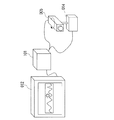
第3および第4の実施の形態は、第1および第2の実施の形態が、カメラ005そのものを回転して得た複数の部分画像を合成するのに対し、カメラ005の前面でミラー001を回転させて複数の部分画像を取得することに特徴がある。図32は、ミラー001の回転とカメラ005の回転の対応を説明するための図であり、右側がカメラを回転した場合、左側がカメラ前面でミラーを回転した場合の視野を図示している。
【0097】
図32に示すように、画像と実際の上下左右の対応が変化することや幾何的な歪みを除けば、ミラー001をカメラ005の光軸周りに回転させることはカメラ005のパン操作に、また、ミラー001をカメラ光軸に垂直な軸周りに回転させることはカメラ005のチルト操作に相当する。そのため、ミラー001を用いた場合においても、単純に合成したのでは視差の影響を受けて合成画像上に形状や位置の不連続が発生する場合がある。第3および第4の実施の形態では、この視差による画質低下の影響を、第1および第2の実施の形態と同様の合成手法を適用することで低減する。
【0098】
以下の説明において、第1および第2の実施の形態の実施例と同じ名称を持つ構成要素は基本的に同じ機能を提供する。特に説明の無い個所は、第1および第2の実施の形態の実施例とすべて同一とし、第1および第2の実施の形態の実施例との差異を中心に説明する。
図33は、第3の実施の形態の実施例の構成を説明するための図であり、この図を用いて画像を入力する際の各構成の説明を行う。
図33において、筐体101には、上記実施の形態におけるミラー制御手段003、画像属性メモリ004、撮像手段006、撮像制御手段007、画像メモリ008、画像合成手段009、表示制御手段011が格納されており、他の構成要素とケーブルにより接続されている。
【0099】
ミラー001は、ミラー移動手段002により保持されており、水平方向に回転可能である。ミラー移動手段002は、第1および第2の実施の形態の実施例におけるカメラ移動手段014と同様に、ステッピングモータ、原点検出器、ギア、ミラー保持治具を用いて、ステッピングモータの回転出力をギアを介して適切に減速して保持治具の回転として取り出すことで治具に接続されたミラー001の水平方向の回転を実現する。原点検出器は、ミラーの水平方向の回転量を0とみなす基準点を検出するものであり、例えば、ギアに取り付けた磁石とホール素子を組み合せてミラーの水平方向1回転毎に1パルスを発生させるような構成を利用可能である。このような原点検出器は、ステッピングモータと共に頻繁に利用される機器であるため、詳細は割愛する。
【0100】
上記の構成を持つミラー移動手段002の場合、ミラー001の向き、すなわち水平方向における角度は、原点検出器の出力を基準として、ステッピングモータへの出力パルス数と1パルス辺りの回転量、ギアの減速比から求められる。当然のことながら、ミラー移動手段002はここにあげた以外の構成とすることも可能であり、例えば、DCモータ、減速ギア、ミラー固定治具とロータリーエンコーダを用いる構成など様々な実現方法を利用可能である。
ミラー制御手段003は、上記ミラー移動手段002へのパルス送出、送出パルス数の計算および保持、原点検出器による原点検出を行うものであり、通常のステッピングモータ制御に利用される機構と同様であり詳細は割愛する。これはパーソナルコンピュータと、その出力をステッピングモータに適した形式へ変換する機構とを組み合せることでも容易に実現可能である。
【0101】
本実施例においては、ステッピングモータの1パルス当たりの回転量が18度、ギアの減速比18分の1であるとする。この時、ミラー001はステッピングモータへの出力1パルスにつき1度水平方向に回転する。これらは説明を容易にするために仮に設定するものであり、本発明の適用範囲を限定するものではない。当然のことながら、他の回転量を持つステッピングモータ、他の減速比を利用することが可能である。
また、本実施例の説明においてはミラー001は、水平方向に対してのみ回転するものとし、光軸上に回転中心が存在するものとするが、これは説明を容易にするために設定するものであり、本発明の実施例を規定するものではない。ミラー移動手段002の構成を変更することによりミラー001の水平および垂直方向への回転を適用することや、回転中心が光軸上に存在しない場合にも容易に対応可能である。
【0102】
カメラ005は通常のビデオカメラであり、支柱400を介してカメラ005の光軸とミラー001の回転軸が一致するように固定されており、ミラー001を経由した外界の映像がカメラ005により入力されるように配置されている。図34は、カメラ005により撮像した部分画像を合成して合成画像を生成することを説明するためのイメージ図であり、ミラー001、カメラ005、ミラー移動手段002、投影面306と座標系の関係を示している。
【0103】
図34にあるように、本実施例においては、ミラー001を経由してカメラ005により撮像された部分画像300は、ミラー001の回転軸と軸を共有する円筒状の投影面306上に投影され、他の部分画像と合成される。なお、本実施例においては投影面306として円筒面を用いるが、ミラー001の回転中心を中心とする球面等に対応することも可能である。これらの投影面306を平面に展開したものを合成画像とする。
また、ミラー001の回転範囲が180度未満の場合は、円筒面上や球面上ではなく、平面とすることも可能なことは、第1および第2の実施の形態の実施例と同様である。
【0104】
図35は、投影による合成処理を説明するための図であり、ミラー001を経由してカメラ005の画像平面と投影面との関係を示している。
図35においては、ピンホールカメラモデルにて表現したカメラ005の視点o301を原点として、カメラ005により取得される部分画像に相当する画像平面302の各軸と平行なX軸、Y軸、および、カメラ005の光軸方向にZ軸を持つ3次元座標系が設定されている。カメラ005の焦点距離をfとすると、画像平面302はZ軸方向の距離fの位置に存在する。ミラー005は平面として表現され、Z軸上の回転中心c304を中心に回転し、その単位法線ベクトルをn303とする。投影面306はZ軸を軸とする円筒面であり、その半径をDとする。
【0105】
ミラー001の単位法線ベクトルn303は、水平、すなわちXY平面と平行な状態を基準に、X軸、Y軸、Z軸の各軸周りの回転量φ、ρ、θを用いて、
【数16】
【0106】
図18は、本実施例における処理の流れを説明するための図である。
以下、図18に基づいて、本実施例における処理の流れを詳細に説明する。
本実施例における画像入力装置100は、まず、1枚の広視野画像を構成する画像数、各部分画像を取得すべき位置、ミラー移動手段002の原点への移動、ミラー制御手段003内の出力パルス数を計数するカウンタの初期化等、各構成要素に必要な初期化を行う(ステップA01)。第1および第2の実施の形態の実施例と同様であるため詳細は割愛する。
なお、部分画像iを取得すべきミラー001の向きを水平方向の角度θiで表現するものとする。これらは説明のために仮に設定するものであり、本説明の適用範囲を限定するものではなく、他の表現手法を利用可能である。ミラー001の水平方向、すなわちZ軸周り以外の回転も可能な場合は、各軸周りの回転量も含めて取得すべき向きを設定すれば良い。
【0107】
また、画像メモリ008は、N枚の部分画像及び合成画像を格納するのに必要十分な大きさを持っており、画像属性メモリ004は、部分画像の大きさ、取得時のミラーの姿勢、部分画像が格納されている画像メモリ上の位置、合成画像の大きさ、合成画像が格納される画像メモリ上の位置の各属性情報が格納されているものとする。各部分画像や合成画像の画素値は、これらの属性情報を利用することで参照可能である。このような画像メモリ008および画像属性メモリ004はメモリ素子の組み合わせや、または、コンピュータに搭載されている記憶装置を流用することで容易に実現可能である。
【0108】
初期化終了後、本発明における画像入力装置100は撮像処理を終了するまで、ステップB00〜ステップG00の処理を繰り返す(ステップA02)。処理を終了する条件については、ユーザからの指示、既定時間実行した後終了する等様々な手法を実施可能であるが、本発明の本質ではないので詳細は割愛する。
ミラー制御手段003は、ミラー移動手段002を用いてミラー001の向きを部分画像iの取得位置θiに移動する(ステップB00)。
【0109】
図19は、ミラー移動処理の処理の流れを説明するための図である。
図19において、ミラー制御手段003は、まず、ミラー移動手段002に指示を出し、ミラー001の移動を開始する。すなわち、ミラー移動手段002は、ステッピングモータにパルスを出力してミラーの向きを移動し(ステップB92)、出力パルス数を更新する(ステップB93)。そして出力パルス数から、第1のおよび第2の実施の形態のカメラの角度を求める場合と同様の計算に基づき、ミラー001の向きθを求める(ステップB94)。
【0110】
ここでは、ステップB92においては1パルスを出力し、ステップB94においては、出力パルス数を示すカウンタ値を1増加させるものとする。ただし、これらは仮に設定するものであり、例えば、カメラの水平方向の回転の分解能がより細かな値を持つ場合などは2パルスを一度に出力するなど、ここにあげた例とは異なった値を利用することも可能なことは、第1および第2の実施の形態における実施例と同様である。
その後、ミラー制御手段003は、求めたθと部分画像iを取得すべき位置を示すθiを比較することでミラー001が目的の向きに移動したか否かを監視し(ステップB95)、目的の向きに達した場合はミラー001の移動を終了する。そうでない場合は、再びステップB92に戻り、パルス出力以降の処理を繰り返す。
【0111】
次に、撮像制御手段007は、第1および第2の実施の形態の実施例における撮像処理と同様に、ミラー001を経由してカメラ005が取得した外界の映像を撮像手段006により部分画像として画像メモリ008に、取得時のミラー001の向き、すなわちθiを画像属性メモリ004に、それぞれ取り込む(ステップC00)。ここで、撮像手段の構成は、第1および第2の実施の形態における実施例と同様である。
続いて、画像合成手段009は、取得した部分画像を、視差の影響が低減するように投影面306に投影し、この投影面306を展開して合成画像を更新する(ステップE00)。
【0112】
本実施例における合成処理の流れは、第1および第2の実施の形態の実施例の合成処理の流れを示す図である図7と同様の処理の流れであるが、第1および第2の実施の形態の実施例では、カメラ005の向きを利用したのに対して、本実施例ではミラー001の向きを利用する点およびステップE95における投影手法がミラーの回転中心c304を利用する点が異なっている。
図7において、画像合成手段009はまず、取得直後の部分画像iを合成画像上に投影するために、画像メモリ008内から部分画像iを、また、その取得位置θiを画像属性メモリ004から取得する(ステップE91)。本実施例において、部分画像の各画素に付加された番号、およびその番号を用いて部分画像i上の画素の位置を決定する処理(ステップE92、ステップE93、およびステップE94)は、第1および第2の実施の形態における実施例と同様である。
【0113】
以下、ステップE95およびステップE96における、部分画像上の画素の投影面306への投影処理を、図を用いて詳細に説明する。
まず、部分画像i取得時のミラー位置θiから、部分画像iを取得した時のミラー001の単位法線ベクトルn303を式(16)に対して、θ=θi、ρ=0を代入した、
【数17】
【数18】
視点o301から点p311を通る直線は、パラメータsを用いて、
【数19】
【0114】
ミラー001上の点r305と、単位法線ベクトルn303と、回転中心c304の間の関係は、内積を用いて、
【数20】
【数21】
【0115】
ここで、直線の方向ベクトルlが、単位法線ベクトルnで示される平面において反射した後の方向ベクトルは、単位法線ベクトルのX、Y、Z成分により構成される反射を示す行列Rを用いて
【数22】
【数23】
【0116】
図37は、この視差の問題を説明するための図であり、上記の投影手法では、空間上の点q309が、破線および実線で示されるようにミラー001が異なる向きの時に、投影面306上の異なる2点p’308に投影されることを示している。この視差は、ミラー001の回転中心c304と投影面306への投影の中心が一致していないことに起因するものである。
この問題を解決するために、本発明における画像入力装置では、第1および第2の実施の形態の実施例において、カメラ回転中心を投影の中心としたのと同様に、画像合成手段009における画像合成処理において回転中心c304を投影の中心として、各部分画像を投影面306上に投影する。
【0117】
図36は、回転中心c304を投影中心とする投影手法を説明するための図である。回転中心c304から式(23)で表現される反射直線307上の点q309へのベクトルは、
【数24】
【数25】
【0118】
しかしながら、空間上の点q309が遠方、すなわち、パラメータsの値が大きくなっていく場合を考えると、回転中心c304と点p’’310を結ぶベクトルは徐々に、反射直線307の方向ベクトルに近づき、最終的には平行な方向に収束するという特性がある。例えば、レンズの焦点距離5.5、回転中心が(0,0,30)の時には、反射点からの距離が約1000程度でほぼ収束する。すなわち、回転中心c304から見た反射直線307上の点を投影面306上に投影した場合、交点p’310は、反射直線307と平行で回転中心c304を通る直線と投影面306との交点に収束する。これは、視点o301と画像平面302上の点p311とを結ぶ直線がミラー001により反射した反射直線307上にある空間上の点のほとんどが、この交点に投影されることを示している。このことから、この収束点を投影点312とすることにより、上記の視差の問題を大幅に低減可能であり、得られる合成画像の品質を著しく向上させられる。
【0119】
そこで、ステップE95においては、部分画像i上の各点(xj,yj,f)から、式(23)で示される反射直線307と同じ方向ベクトルを持ち回転中心c304を通る直線と、投影面306である半径Dの円筒面との交点の位置ベクトルを、
【数26】
【0120】
また、合成画像の大きさの更新タイミングおよび手法についても第1および第2の実施の形態の実施例と同様である。
部分画像i上の全画素の合成画像上への投影処理が終了したか否かを全画素数を示すJと変数jの比較により判断し、全画素への処理が終了した場合には、画像合成処理を終了する(ステップE93)。
合成処理(ステップE00)における部分画像iの合成画像への投影処理が終了した後、表示制御手段011は、更新された合成画像を画像メモリ008から読み出し、第1および第2の実施の形態の実施例と同様に、表示手段012に表示する(ステップG00)。
【0121】
更新された合成画像の表示が終了した後、第1および第2の実施の形態の実施例と同様に、次の部分画像を取得するべく、図18におけるステップA02以降を繰り返す。図31に示したような、継続的に更新される合成画像を用いた機能の例を利用可能なことも第1および第2の実施の形態の実施例と同様である。
なお、上記の説明においては、ミラー移動、撮像、画像合成、表示の各処理を順に実行するものとして説明したが、これらは並列に実行するように構成することも可能である。
【0122】
以下、第3の実施の形態の第2の実施例として、各処理を並列に構成した場合について、第3の実施の形態の第1の実施例と比較しながら、図を用いて詳細に説明する。
第3の実施の形態の第2の実施例においても、外観、各手段の構成、投影面、座標系の設定など、処理の流れに関わる個所以外は、第3の実施の形態の第1の実施例とすべて同一とする。
図20は、各処理を並列に構成した場合の全体の処理の流れを説明するための図である。
図20における各処理は、図18における第3の実施の形態の第1の実施例における処理の流れと比較して、ミラー移動(ステップB00),撮像(ステップC00)、画像合成(ステップE00)、表示(ステップG00)の各処理が同期をとりながら、並列に実行されることを特徴とする。
【0123】
第3の実施の形態の第1の実施例と同様の初期化処理(ステップA01)、終了確認処理(ステップA02)を経た後、各処理はそれぞれ動作を開始する。
図21は、第3の実施の形態の第2の実施例におけるミラー移動処理(ステップB00)の処理の流れを詳細に説明するための図である。
第2の実施例におけるミラー移動処理は、第1の実施例と比較して、ミラー001を個々の画像取得位置に移動するのではなく、ミラーの向きを記録しながら継続的に移動することに特徴がある。
すなわち、ミラー移動処理は、図20における終了確認処理(ステップA02)からの指示があるまで、パルス出力(ステップB92)からミラー位置計算(ステップB94)の処理を継続して行い、得られたミラー位置をミラー制御手段015内に記録(ステップB96)という処理を繰り返す。撮像処理(ステップC00)は、第1および第2の実施の形態における実施例と同様に、このミラー位置を参照して処理を行う。ここではミラー位置として水平方向の角度が伝えられるものとするが、出力パルス数を直接送出する等、撮像処理においてミラーの向きが確認できる手法であれば、どのような形態でも良い。また、水平だけでなく、各軸周りの回転量を伝えるように構成可能なことも、第1および第2の実施の形態における実施例と同様である。
【0124】
パルス出力(ステップB92)からミラー位置計算(ステップB94)までの各処理は、第3の実施の形態の第1の実施例における処理の流れを説明する図である図19において同一名称を持つ処理と同様の処理である。
図20における終了確認処理(ステップA02)の指示があった場合は(ステップB97)、第3の実施の形態における第1の実施例と同様に、ミラー001の移動を停止し、処理を終了する。
【0125】
図22は、第3の実施の形態の第2の実施例における撮像処理(ステップC00)の処理の流れを詳細に説明するための図である。
本実施例における撮像処理の流れは、第1の実施の形態の第2の実施例における撮像処理の流れを示す図である図10と同様の処理の流れであるが、先の実施例ではカメラ005の向きを取得したのに対して(ステップC91)、本実施例ではミラー001の向きを取得し(ステップC95)、利用する点が異なっているのみであり、詳細は割愛する。
【0126】
本実施例における合成処理の流れは、第1の実施の形態の第2の実施例における合成処理の流れを示す図である図11と同様の処理の流れであるが、第1の実施の形態の第2の実施例ではカメラ005の向きを利用したのに対して、本実施例ではミラー001の向きを利用する点、およびステップE04における投影手法が、第3の実施の形態の第1の実施例における処理と同様に、ミラーの回転中心c304を利用する点が異なっている。
表示処理は、表示制御手段011が、合成画像を継続的に画像メモリ008から読み出し、表示手段012に表示する(ステップG00)。継続的に読み出し、表示されるため、更新された合成画像は直ちに表示手段012に表示される点や、合成画像の一部だけをユーザの指示に応じて選択的に表示するように構成することや、複数のユーザが同一の合成画像上から異なった地点を切り出して表示手段012に表示する機能を提供可能なことは先の実施例と同様である。
【0127】
このように各処理を並列に構成することで、第3の実施の形態の第1の実施例と比較して、画像取得から画像を合成するに至る一連の処理の流れにおいて、一つの処理の遅れが他の処理にも影響を与え全体の動作速度が低下するという問題を防げるという長所が生じる。
次に、本発明の画像入力装置における第4の実施の形態の実施例を、図を参照して詳細に説明する。
【0128】
第3の実施の形態においては、部分画像の取得のすべき位置と実際に部分画像を取得した際のミラーの向きには差が発生しないものとして構成されている。しかしながら、ミラー移動手段002によるミラー向き検出精度が低い場合、さらには、画像取得指示から実際に部分画像が取得されるまでの遅延が大きい場合には、部分画像の取得位置に大きな誤差が含まれる場合があり、合成画像の精度を著しく低下させるという問題が発生する場合がある。
【0129】
本発明の第4の実施の形態は、第1の実施の形態に対する第2の実施の形態と同様に、このような取得位置に含まれる誤差の問題を解消するためになされたものであり、第3の実施の形態と比較して、各部分画像の取得位置に含まれる誤差を解消し高精度の合成画像を取得可能とするために、部分画像間に位置あわせを適用する位置あわせ手段が追加されたことを特徴とする。
【0130】
本実施例においても、第3の実施の形態における実施例の構成を説明するための図である図33と同様の外観を持つが、筐体101には、ミラー制御手段003、画像属性メモリ004、撮像手段006、撮像制御手段007、画像メモリ008、画像合成手段009、表示制御手段011の各構成要素に加えて、さらに、位置合わせ手段013が格納されており、他の構成要素とケーブルにより接続されている。第3の実施の形態の第1の実施例と比較して、同じ名称を持つ構成要素は同じ機能を提供するが、画像属性メモリ004は、部分画像取得時のミラーの向きの情報および位置合わせ手段013により求められた各部分画像の位置補正量をそれぞれ、格納する。また画像合成手段009は、画像属性メモリ004内の部分画像の取得位置と、位置合わせ手段013により求めた部分画像の位置補正量を利用して合成位置を求めるように構成されている。
【0131】
図23は、本実施例における処理の流れを説明するための図である。図23において、第3の実施の形態の第1の実施例における処理の流れを説明するための図である図18と同じ名称を持つ構成要素は同じ機能を提供するものとする。なお、第4の実施の形態の実施例において、外観、各手段の構成、投影面、座標系の設定など、位置合わせ手段013および位置合わせ処理(ステップD00)に関わる個所以外は、第3の実施の形態の実施例とすべて同一とする。
図23における初期化(ステップA01)は、第3の実施の形態の第1の実施例と比較して、部分画像の合成位置を求める際の位置補正量値を0に初期化する処理が追加されている。終了確認(ステップA02)、ミラー移動(ステップB00)、撮像(ステップC00)は、第3の実施の形態の第1の実施例と同様である。
【0132】
本実施例における位置合わせ処理(ステップD00)の流れは、第2の実施の形態の実施例における位置合わせ処理の流れを示す図である図13と同様の処理の流れであるが、第2の実施の形態の実施例ではカメラ005の向きを利用したのに対して、本実施例ではミラー001の向きを利用する点が異なっている。
ステップD00における位置合わせ処理結果を利用して、画像合成手段009は、第3の実施の形態における実施例と同様に、部分画像に含まれる視差の影響を低減しながら各部分画像を合成画像上に投影する(ステップE00)。本実施例においては、第3の実施の形態の第1の実施例における合成処理の処理の流れを説明する図である図7と、ステップE02において、画像属性メモリ004に格納された部分画像を取得した時のミラー001の向き情報と、位置合わせ手段013により求めた合成位置補正量とを用いて部分画像の合成位置を求める点が異なるのみであり、その他の投影手法に関しては第3の実施の形態の第1の実施例と同様である。
【0133】
このように、位置合わせ手段013により部分画像iの取得位置に含まれる誤差を解消し、高精度の合成画像を生成することが可能となる。
第4の実施の形態においても、第3の実施の形態と同様に、各処理が並列に実行されるように構成することが可能であり、この時、ステップD00における位置合わせ処理は、第2の実施の形態の実施例における位置合わせ処理の流れを示す図である図15と同じ処理の流れとなるが、第2の実施の形態の実施例ではカメラ005の向きを利用したのに対して、本実施例ではミラー001の向きを利用する点が異なっている。
【0134】
また、第2の実施の形態の実施例と同様に、部分画像の取得および画像合成が継続的に、かつ、同じ位置を目標に行われる場合には、各部分画像の取得位置に含まれる誤差は安定すると考えられるため、継続的に画像取得および合成が行われている時、ある時点で求めた部分画像iに対する位置補正量は、次に部分画像iを取得する時にも高い精度で利用できる。このことから、第4の実施の形態の第1の実施例に対して、図24のように、位置合わせ処理(ステップD00)と合成処理(ステップE00)が並列に実行されるように構成可能である。図24は、第2の実施の形態の実施例における処理の流れを示す図である図14と同様の処理の流れであるが、カメラ005ではなく、ミラー001の移動を行う点(ステップB’00)と、各処理においてカメラ005の向きではなくミラー0001の向きの情報を利用する点が異なっている。
【0135】
また、第3および第4の実施の形態の実施例における画像合成処理では、部分画像iを合成画像上に投影するという手法を説明したが、第1および第2の実施の形態の実施例と同様に、合成画像上の点を画像平面上に投影することで合成画像上の点の画素値を決定するように構成することも可能である。
このときの画像合成処理の流れは、第1及び第2の実施の形態における実施例と同様に、図16および図17となる。図17は、画像合成処理を他の処理と並列に実行する場合を示している。
【0136】
この画像合成処理における各処理は、第1および第2の実施の形態の実施例においてはカメラ005の向きを利用したのに対してミラー001の向きを利用するように構成される点、および、合成画像上の位置(Xk,Yk)から部分画像上の位置(xk,yk)を求める際の計算が異なるのみである。以下、第3及び第4の実施の形態の実施例において、合成画像上の点を画像平面上に投影することで合成画像上の点の画素値を決定する場合の計算手法について説明する。
【0137】
合成画像上の点(Xk,Yk)から投影面306上の投影点312の3次元座標(X,Y、Z)は、第1および第2の実施の形態における実施例と同様に、
【数27】
【0138】
投影点312とミラー回転中心304を通る直線の方向ベクトルは、
【数28】
【数29】
【0139】
この方向ベクトルを持ち、視点o301、すなわち、原点を通る直線は、パラメータsを用いて
【数30】
【数31】
求めた位置(xk,yk)から合成画像上の画素値を決定する手法は、第1および第2の実施の形態における実施例と同様であり、詳細は割愛する。
【0140】
このように合成画像上の点から部分画像上の対応点を求める場合は、座標の丸め誤差に伴う空白画素の発生が合成画像上に生じないという特徴があるのは、第1および第2の実施の形態における実施例と同様である。また計算により求めた合成画像サイズが指定サイズに収まるように拡大・縮小比率を求め、この比率を合成画像の座標系に適用することで上記の画像投影手法を利用可能なことも、同様である。さらには、他の処理と並列に実行されるように構成可能なことも、第1および第2の実施の形態における実施例と同様である。
【0141】
図40は第4の実施の形態における実施例において、合成画像上の画素値を部分画像上の対応点から共一次内挿により求めた画像の例を示している。図40(A)が画像合成処理において得られる合成画像の一状態を示しており、図40(B)は表示処理において、合成画像から中央部のみを切り出して表示される様子を示している。
【0142】
また、各第3および第4の実施の形態における実施例においては、図33に示すように、カメラ005が上方に、ミラー001が下方にある形態について説明したが、本発明の適用範囲はこれに限定されるものではない。図38および図39は、他の実施の例を示したものであり、カメラ005を下方に、ミラー001を上方に設置する場合の例を示している。図39が外観を、図38が断面図をそれぞれ示している。このような構成とした場合、ミラー移動手段002の構成要素であるミラー保持治具をミラー両端にして各部分画像に治具が映り込まないようにすることで、カメラ005を支える支柱400が視界に入ることを防ぐことが可能となる。
【0143】
また、第4の実施の形態における実施例においては、ミラー移動手段002が部分画像取得時のミラー001の向きを検出するとしたが、位置合わせ手段013を構成要素とする場合は、θの存在範囲を適切に設定することでミラー001の向きの検出機構を省くことも可能である。
また、上記の各実施の形態における実施例においては、ビデオカメラを、固定焦点距離を持つものとして扱ったが、ズームレンズ等により焦点距離が可変な場合にも、現在の焦点距離を装置に伝える手段を設けることで容易に対応可能である。
【0144】
また、上記各実施の形態における実施例においてはカメラ005の光学系を周辺減光や歪曲収差を持たない単純なピンホールモデルにて説明したが、これらの歪みを取り除く手段を撮像制御手段007に追加することによりこのような光学系に起因する歪みを生じるカメラ005に対しても本発明は適用可能である。このようなカメラパラメータの測定技術については、「出口『カメラキャリブレーション手法の最近の動向』、情処研報Vol.93、No.25、CV82−1、1993」に詳しく紹介されているため、ここでは割愛する。
また、各実施例において、カメラ005またはミラー001を、それぞれカメラ移動手段014またはミラー移動手段002により自動的に移動するものとしたが、これらを簡略化してユーザが手動でカメラ005またはミラー001を移動可能な構成にすることも可能である。
【0145】
次に本発明の第5の実施の形態に係る画像入力装置の構成を図41及び図42に示す。図41は画像入力装置の機構部を含む全体構成を示し、図42は図41に示す機構部の側面を示している。これらの図において、本実施の形態に係る画像入力装置は、機構部と制御部とからなり、具体的には、機構部は、カメラ本体610とカメラレンズ611からなり被写界を撮像するカメラ600と、その側面のうち2面に反射面602a−1、602a−2が形成され、被写界からの反射光をカメラ600のカメラレンズ611方向に光路変換するためにカメラ600の前方に配置された三角柱ミラー602aと、三角柱ミラー602aをカメラ600の光軸回りに回転させるミラー回転機構603とを有している。尚、カメラ600、ミラー602aは図4に示す第4の実施の形態に係る画像入力装置のカメラ005、ミラー001に相当し、ミラー回転機構603は図4に示す第4の実施の形態に係る画像入力装置におけるミラー移動手段002に相当する。
【0146】
また制御部は、三角柱ミラー602aの回転に伴ってカメラより入力される複数の画像を合成して広視野角画像を生成する処理手段500と、処理手段500からの制御信号に従ってミラー回転機構603を制御するミラー回転制御手段501とを有している。ミラー回転制御手段501は、図4に示す第4の実施の形態に係る画像入力装置のミラー制御手段003に相当する。
【0147】
処理手段500は、カメラ600により撮像された画像を取得して処理する画像取得手段502と、画像取得手段502で処理された画像を反射面602a−1からの反射光を撮像することにより得られた画像と反射面602a−2からの反射光を撮像することにより得られる画像に分離する画像分離手段505と、画像分離手段505で分離された画像をそれぞれ独立に合成処理する画像合成手段503−1、503−2と、画像合成手段503−1、503−2で合成された画像を、それぞれの更新部分が広視野画像に反映されるように統合することで合成画像を更新する画像更新手段504とを有している。画像合成手段503−1は第1の画像合成手段に、画像合成手段503−2は本発明の第2の画像合成手段に、それぞれ相当する。
尚、画像取得手段502は図4に示す第4の実施の形態に係る画像入力装置の撮像手段006及び撮像制御手段007に相当する。画像合成手段503−1及び503−2は、図4に示す第4の実施の形態に係る画像入力装置の画像合成手段009に相当する。
【0148】
上記構成からなる本発明の第5の実施の形態に係る画像入力装置の動作について説明する。上記構成において、処理手段500は、ミラー回転制御手段501を介してミラー回転機構603を制御し、三角柱ミラー602aを回転制御する。
処理手段500は、三角柱ミラー602aの回転速度を自由に設定できるが、通常は一定速度で回転させるように制御する。被写界からの反射光は、三角柱ミラー602aの反射面602a−1と反射面602a−2で光路変換されてカメラ600に入力され、この結果、カメラ600により被写界が撮像され、その映像信号がカメラ本体610から画像取得手段502に送出される。
【0149】
画像取得手段502は、三角柱ミラー602aが回転した状態で、カメラ本体610より順次、画像を取得し処理する。三角柱ミラー602aが一定速度で回転している場合は、一定時間毎に画像を取得すれば、画像入力装置の周囲における被写界の画像を一定間隔で取得することが可能となる。
さて、画像取得手段502で取得された画像は、三角柱ミラー602aの反射面602a−1からの反射光を撮像することにより得られた画像と、反射面602a−2からの反射光を撮像することにより得られた画像が合わさったものである。
【0150】
そこで画像分離手段505は、画像取得手段502により取得され処理された各画像を三角柱ミラー602aの2つの反射面602a−1、602a−2に対応させて分離して、分離された画像をそれぞれ画像合成手段503−1と画像合成手段503−2に送出する。
画像合成手段503−1、503−2では、それぞれ独立に画像の合成処理を行い、合成された結果を画像更新手段504へ送出する。
画像更新手段504では、画像合成手段503−1、503−2から送られてきた各画像から更新された部分を広視野画像上に重ね書きすることで順次広視野画像を更新し、図示していない表示手段に出力する。
【0151】
画像合成手段503−1及び503−2における合成処理は、本発明における第1〜第4の実施の形態における合成処理と同様である。
【0152】
図43は、図41に示した画像入力装置におけるカメラ600で撮像された各画像M1、M2、M3、M4、…の例を示しており、上下方向が一致するように回転して配置した様子を示している。
図43にあるように三角柱ミラー602aの2つの反射面602a−1と反射面602a−2を介して撮像された各画像領域における境界線Lの位置は,カメラ600のカメラレンズ611の光軸に対する三角柱ミラー602aの相対角度で決まる。画像分離手段505は、この境界線Lに従って撮像した画像を2つに分離する。分離された各画像は取得時のミラー角度が180度異なる2枚の部分画像とみなすことができるため、画像合成手段503−1及び503−2において、本発明における第1〜第4の実施の形態における画像合成処理と同様の処理でそれぞれ独立に合成される。
【0153】
画像更新手段504は、画像合成手段503−1及び503−2において生成された各合成画像のうち、撮像した画像が反映されている部分のみを抜き出して広視野画像上の対応部分に重ね書きすることで広視野画像を更新する。撮像した画像が反映されている部分は、例えば、分離後の画像上の各画素が合成画像上に投影される領域の外接矩形とすることで容易に判断可能である。また図44は図43における画像M2が広視野画像に合成される様子を説明するための図である。 図44において、画像M2は、三角柱ミラー602aの反射面602a−1を介して撮像された画像M2−1と、反射面602a−2を介して撮像された画像M2−2とに分離された後、それぞれ独立に合成画像1及び合成画像2上に合成される。この時、両者の合成位置は互いに180度異なっている。画像更新手段504は、合成画像1、合成画像2それぞれの更新された部分の外接矩領域R−1とR−2を抜き出して重ね書きすることで広視野画像を更新する。
以上のように、本実施の形態においては、個々の撮像した画像には、カメラから見たある方向の被写体と、それと180度反対方向の被写体がそれぞれ同時に撮像されている。したがって、三角柱ミラー602aが180度回転しただけで360度全方位の広視野画像を取得することができる。すなわち、三角柱ミラー602aが360度回転する度に、広視野画像は2回更新されることになる。すなわち、本発明の第4の実施の形態に係る画像入力装置に比べて、広視野画像を入力する際のフレームレートを2倍、高速化することができる。ここでは、2つの独立した画像合成手段が存在するものとして説明したが、各合成処理を並列に行う必要がない場合は、本発明における第1〜第4の実施の形態において利用した画像合成手段を、分離後の各画像に順番に適用するように構成することも可能である。
【0154】
以上説明したように本発明の第5の実施の形態に係る画像入力装置によれば、三角柱ミラーを用いてカメラにより撮像した2方向の画像を同時に合成し、更新することにより、ミラーがカメラの光軸回りを1回転するのに要する時間の1/2で360度全方位の広視野画像を1回、更新することが可能となる。
【0155】
次に本発明の第6の実施の形態に係る画像入力装置の構成を図45及び図46に示す。図45は画像入力装置の機構部を含む全体構成を示し、図46は図45に示す機構部の側面を示している。これらの図において、本実施の形態に係る画像入力装置は、機構部と制御部とからなり、具体的には、機構部は、カメラ本体610uとカメラレンズ611uからなるカメラ601uと、カメラ本体610dとカメラレンズ611dからなり、カメラ601uとカメラレンズの光軸を一致させて互いに向き合うように配置されたカメラ601dと、カメラ601uとカメラ601dとの間に配置され反射面602b−1、602b−2を有し、被写界からの反射光をカメラ601u、601dのカメラレンズ方向に光路変換する両面ミラー602bと、両面ミラー602bをカメラ601u、601dの光軸回りに回転させるミラー回転機構603と、ミラー回転機構603の回転を両面ミラー602bに伝達するための両面ミラー602bを保持している中空ギア604及びギア605とを有している。カメラ601uは、本発明の第1のカメラに、カメラ601dは、本発明の第2のカメラに、それぞれ相当する。
尚、両面ミラー602bは、図4に示す本発明の第4の実施の形態に係る画像入力装置のミラー001に、ミラー回転機構603は図4のミラー移動手段002に、それぞれ相当する。
【0156】
また制御部は、ミラーの回転に伴ってカメラ601u、601dより入力される複数の画像を合成して広視野角の画像を生成する処理手段500と、処理手段500から出力される制御信号に従ってミラー回転機構603を制御するミラー回転制御手段501とを有している。
処理手段500は、カメラ601uにより撮像された画像を取得して処理する画像取得手段502uと、画像取得手段502uで処理された画像を合成処理する画像合成手段503uと、カメラ601dにより撮像された画像を取得して処理する画像取得手段502dと,画像取得手段502dで処理された画像を合成処理する画像合成手段503dと、画像合成手段503u、503dにより合成された各画像から更新された部分を広視野画像に重ね書きして更新する画像更新手段504とを有している。尚、ミラー回転制御手段501は、図4に示す本発明の第4の実施の形態に係る画像入力装置のミラー制御手段003に、画像取得手段502u、502dは、図4に示す本発明の第4の実施の形態に係る画像入力装置の撮像手段006及び撮像制御手段007に、画像合成手段503u、503dは、図4に示す本発明の第4の実施の形態に係る画像入力装置の画像合成手段009に、それぞれ相当する。
【0157】
ここで、画像取得手段502uは本発明の第1の画像取得手段に、画像取得手段502dは本発明の第2の画像取得手段に、画像合成手段503uは本発明の第1の画像合成手段に、画像合成手段503dは本発明の第2の画像合成手段に、それぞれ相当する。
【0158】
次に上記構成からなる本発明の第6の実施の形態に係る画像入力装置の動作について説明する。上記構成において、処理手段500は、ミラー回転制御手段501を介してミラー回転機構603を制御し、ギア605を回転駆動する。ギア605の回転は、中空ギア604を介して両面ミラー602bに伝達される.中空ギア604は、両面ミラー602bの反射面602b−2で反射された光をカメラ601dに入力されるように中空形状をしている。
【0159】
処理手段500は、両面ミラー602bの回転速度を自由に設定できるが、通常は一定速度で回転させるように制御する。被写界からの反射光は、両面ミラー602bの反射面602b−1と反射面602b−2で光路変換されてそれぞれ、カメラ601u及びカメラ601dに入力され、この結果、カメラ601u及びカメラ601dにより被写界が撮像され、その映像信号がカメラ本体610u及びカメラ本体610dから、画像取得手段502u及び画像取得手段502dに送出される。
【0160】
画像取得手段502u及び画像取得手段502dは、両面ミラー602bが回転した状態で、カメラ本体610u及びカメラ本体610dから順次、画像を取得し、処理する。両面ミラー602bが一定速度で回転している場合は、一定時間毎に画像を取得すれば、画像入力装置の周囲における被写界の画像を一定間隔で取得することが可能となる。
画像取得手段502u及び画像取得手段502dで取得された画像は、それぞれ画像合成手段503u及び画像合成手段503dで合成処理され、画像更新手段504へ送出される。
画像更新手段504では、画像合成手段503u及び画像合成手段503dから送られてきた各画像から更新された部分を広視野画像上に重ね書きすることで順次広視野画像を更新し、図示していない表示手段に出力する。
【0161】
図47は、本実施の形態における撮像から広視野画像更新に至る処理を説明するための図である。本実施の形態では、2つのカメラと、それらに挟まれた両面ミラー602bを用いているため、あるミラー位置に対して撮像位置が180度異なる2枚の画像が取得されることを特徴とする。この2枚の画像を、本発明における第5の実施の形態と同様に、画像合成手段503u及び画像合成手段503dによりそれぞれ合成して合成画像を生成し、画像更新手段504により各合成画像の更新された部分を広視野画像上に重ね書きすることで広視野画像を更新する。すなわち、図47において、あるミラー角度に対して両面ミラー602bの反射面602b−1を経由して撮像された画像M1−1と、同じく反射面602b−2を経由して撮像された画像M1−2は、それぞれ合成画像1及び合成画像2に合成される。この時、両者の合成位置は互いに180度異なっている、それぞれの更新領域の外接矩形領域R−1とR−2に相当する部分画像が広視野画像上に重ね書きされる。
本実施の形態における画像合成は、カメラ601uとカメラ601dのそれぞれの処理系統に対して本発明の第4の実施の形態に係る画像入力方法をそのまま適用できる。
本実施の形態では、2つのカメラと、それらに挟まれた両面ミラー602bを用いているため、ミラーが1回転する間に2つの360度全方位広視野画像が生成される。言い換えれば,両面ミラー602bが1回転する間に、360度全方位広視野画像が2回更新されることになる。すなわち、第5の実施の形態と同様に、第4の実施の形態に係る画像入力装置に比べて,広視野画像を入力する際のフレームレートを2倍、高速化することができる。
尚、ここでは、2つの独立した画像合成手段が存在するものとして説明したが、各合成処理を並列に行う必要がない場合は、本発明における第1〜第4の実施の形態において利用した画像合成手段を、各画像に順番に適用するように構成することも可能である。
【0162】
以上 説明したように本発明の第6の実施の形態に係る画像入力装置によれば、両面ミラーを用いてカメラにより撮像した2方向の画像を同時に合成し、更新することにより、ミラーがカメラの光軸回りを1回転するのに要する時間の1/2で360度全方位の広視野画像を1回、更新することが可能となる。
また2台のカメラと両面ミラーを組み合せることによりで広視野画像を高速に入力することが可能になると共に、更に本発明の第4の実施の形態に係る画像入力装置と同様の解像度の広視野画像を生成することができる。
【0163】
尚、回転可能に保持されたカメラを回転駆動することにより撮影方向を変化させながら被写界の部分を撮影し、取得した被写界の複数の部分画像を投影面上に投影し、その投影結果に基づいて合成画像面上に合成し、広視野の合成画像を入力する画像入力装置において、前記複数の部分画像の合成時に前記カメラの回転中心を投影の中心とし、前記カメラの視点と前記複数の各部分画像が形成される画像平面上における部分画像上の画素とを結ぶ直線に平行で、かつ前記カメラの回転中心を通る直線と空間上に設定された投影面との交点を前記部分画像上の画素の投影点とする画像合成手段を有することを特徴とする画像入力装置の機能を実現するためのプログラムをコンピュータにより読み取り可能な記録媒体に記録して、この記録媒体に記録されたプログラムをコンピュータシステムに読み込ませ、実行することにより画像入力を行うようにしてもよい。
この記録媒体に記録されたプログラムをコンピュータシステムに読み込ませ、実行することにより、レンズの主点以外の点を中心としてカメラを回転した場合にも、部分画像に含まれる視差の影響を低減した良好な広視野の合成画像が得られる。
【0164】
また回転可能に保持されたカメラを回転駆動することにより撮影方向を変化させながら被写界の部分を撮影し、取得した被写界の複数の部分画像を投影面上に投影し、その投影結果に基づいて合成画像面上に合成し、広視野の合成画像を入力する画像入力装置において、カメラの撮影方向を変更するカメラ移動手段と、前記カメラ移動手段にカメラの撮影方向を変更するように指示すると共にカメラの姿勢情報を各部に伝達する姿勢制御手段と、部分画像及び該部分画像を合成して作成した合成画像が格納される第1の記憶手段と、部分画像及び合成画像に関連する属性情報及び部分画像取得時のカメラの姿勢情報が格納される第2の記憶手段と、前記カメラが撮影した画像を取り込み該取り込んだ画像から部分画像を取得し、該部分画像を前記第1の記憶手段に格納し、前記姿勢制御手段より受け取った前記カメラの部分画像取得時の姿勢情報及び、部分画像と合成画像に関連する属性情報を前記第2の記憶手段に格納する部分画像取得手段と、カメラの回転中心を投影の中心とし、前記カメラの視点と前記複数の各部分画像が形成される画像平面上における部分画像上の画素とを結ぶ直線に平行で、かつ前記カメラの回転中心を通る直線と空間上に設定された投影面との交点を前記部分画像上の画素の投影点とするように投影点を決定し、前記第1、第2の記憶手段の記憶内容を参照して各部分画像を合成し、合成画像を前記第1の記憶手段に格納する画像合成手段とを有することを特徴とする画像入力装置の機能を実現するためのプログラムをコンピュータにより読み取り可能な記録媒体に記録して、この記録媒体に記録されたプログラムをコンピューシステムに読み込ませ、実行することにより画像入力を行うようにしてもよい。
この記録媒体に記録されたプログラムをコンピューシステムに読み込ませ、実行することにより、レンズの主点以外の点を中心としてカメラを回転した場合にも、部分画像に含まれる視差の影響を低減した良好な広視野の合成画像が得られる。
【0165】
また回転可能に保持されたカメラを回転駆動することにより撮影方向を変化させながら被写界の部分を撮影し、取得した被写界の複数の部分画像を投影面上に投影し、その投影結果に基づいて合成画像面上に合成し、広視野の合成画像を入力する画像入力装置において、カメラの撮影方向を変更するカメラ移動手段と、前記カメラ移動手段にカメラの撮影方向を変更するように指示すると共にカメラの姿勢情報を各部に伝達する姿勢制御手段と、部分画像及び該部分画像を合成して作成した合成画像が格納される第1の記憶手段と、部分画像及び合成画像に関連する属性情報及び部分画像取得時のカメラの姿勢情報が格納される第2の記憶手段と、前記カメラが撮影した画像を取り込み該取り込んだ画像から部分画像を取得し、該部分画像を前記第1の記憶手段に格納し、前記姿勢制御手段より受け取った前記カメラの部分画像取得時の姿勢情報及び、部分画像と合成画像に関連する属性情報を前記第2の記憶手段に格納する部分画像取得手段と、前記第1の記憶手段に格納されている各部分画像間の位置関係を求め、求められた位置関係に基づいて前記第2の記憶手段に格納されている各部分画像の合成位置の位置補正量を求め、前記第2の記憶手段に格納する位置合わせ手段と、前記第2の記憶手段に格納されている各部分画像を取得した時のカメラの姿勢情報及び前記位置合わせ手段により求められた位置補正量を用いて各部分画像の合成位置を求め、求めた合成位置に従って、カメラの回転中心を投影の中心とし、前記カメラの視点と前記複数の各部分画像が形成される画像平面上における部分画像上の画素とを結ぶ直線に平行で、かつ前記カメラの回転中心を通る直線と空間上に設定された投影面との交点を前記部分画像上の画素の投影点とするように投影点を決定し、前記第1、第2の記憶手段の記憶内容を参照して各部分画像を合成し、合成画像を前記第1の記憶手段に格納する画像合成手段とを有することを特徴とする画像入力装置の機能を実現するためのプログラムをコンピュータにより読み取り可能な記録媒体に記録して、この記録媒体に記録されたプログラムをコンピュータシステムに読み込ませ、実行することにより画像入力を行うようにしてもよい。
【0166】
この記録媒体に記録されたプログラムをコンピュータシステムに読み込ませ、実行することにより、レンズの主点以外の点を中心としてカメラを回転した場合にも、部分画像に含まれる視差の影響を低減した良好な広視野の合成画像が得られると共に、カメラ移動手段を構成するカメラの角度検出機構の誤差を低減し、高精度の合成画像を作成することが可能となる。
また部分画像取得時におけるカメラの向きの存在範囲を適切に設定することにより、画像入力装置の構成上、カメラ移動手段を構成するカメラの角度検出機構を省くことができる。
【0167】
またカメラの前面に回転可能に保持されたミラーを回転駆動することにより、前記カメラの被写界における撮影範囲を変更しながら被写界の部分を撮影し、取得した被写界の複数の部分画像を投影面上に投影し、その投影結果に基づいて合成画像面上に合成し、広視野の合成画像を入力する画像入力装置において、前記複数の部分画像の合成時に前記ミラーの回転中心を投影の中心とし、前記カメラの視点から部分画像が形成される画像平面上における部分画像の画素を通る光線が前記ミラー上で反射した後の反射光線を示す反射直線に平行で、かつ前記ミラーの回転中心を通る直線と空間上に設定された投影面との交点を前記部分画像上の画素の投影点とする画像合成手段を有することを特徴とする画像入力装置の機能を実現するためのプログラムをコンピュータにより読み取り可能な記録媒体に記録して、この記録媒体に記録されたプログラムをコンピュータシステムに読み込ませ、実行することにより画像入力を行うようにしてもよい。
この記録媒体に記録されたプログラムをコンピュータシステムに読み込ませ、実行することにより、部分画像に含まれる視差の影響を低減した良好な広視野の合成画像が得られる。
【0168】
またカメラの前面に回転可能に保持されたミラーを回転駆動することにより、前記カメラの被写界における撮影範囲を変更しながら被写界の部分を撮影し、取得した被写界の複数の部分画像を投影面上に投影し、その投影結果に基づいて合成画像面上に合成し、広視野の合成画像を入力する画像入力装置において、カメラの撮影方向を変更するように前記ミラーの向きを変更するミラー移動手段と、前記ミラー移動手段に前記ミラーの向きを変更するように指示すると共に前記ミラーの姿勢情報を各部に伝達するミラー制御手段と、部分画像及び該部分画像を合成して作成した合成画像が格納される第1の記憶手段と、部分画像及び合成画像に関連する属性情報及び部分画像取得時の前記ミラーの姿勢情報が格納される第2の記憶手段と、前記カメラが撮影した画像を取り込み該取り込んだ画像から部分画像を取得し、該部分画像を前記第1の記憶手段に格納し、前記ミラー制御手段より受け取った前記ミラーの部分画像取得時の姿勢情報及び、部分画像と合成画像に関連する属性情報を前記第2の記憶手段に格納する部分画像取得手段と、前記ミラーの回転中心を投影の中心とし、前記カメラの視点から部分画像が形成される画像平面上における部分画像の画素を通る光線が前記ミラー上で反射した後の反射光線を示す反射直線に平行で、かつ前記ミラーの回転中心を通る直線と空間上に設定された投影面との交点を前記部分画像上の画素の投影点とするように投影点を決定し、前記第1、第2の記憶手段の記憶内容を参照して各部分画像を合成し、合成画像を前記第1の記憶手段に格納する画像合成手段とを有することを特徴とする画像入力装置の機能を実現するためのプログラムをコンピュータにより読み取り可能な記録媒体に記録して、この記録媒体に記録されたプログラムをコンピュータシステムに読み込ませ、実行することにより画像入力を行うようにしてもよい。
この記録媒体に記録されたプログラムをコンピュータシステムに読み込ませ、実行することにより、部分画像に含まれる視差の影響を低減した良好な広視野の合成画像が得られる。
【0169】
またカメラの前面に回転可能に保持されたミラーを回転駆動することにより、前記カメラの被写界における撮影範囲を変更しながら被写界の部分を撮影し、取得した被写界の複数の部分画像を投影面上に投影し、その投影結果に基づいて合成画像面上に合成し、広視野の合成画像を入力する画像入力装置において、カメラの撮影方向を変更するように前記ミラーの向きを変更するミラー移動手段と、前記ミラー移動手段に前記ミラーの向きを変更するように指示すると共に前記ミラーの姿勢情報を各部に伝達するミラー制御手段と、部分画像及び該部分画像を合成して作成した合成画像が格納される第1の記憶手段と、部分画像及び合成画像に関連する属性情報及び部分画像取得時の前記ミラーの姿勢情報が格納される第2の記憶手段と、前記カメラが撮影した画像を取り込み該取り込んだ画像から部分画像を取得し、該部分画像を前記第1の記憶手段に格納し、前記ミラー制御手段より受け取った前記ミラーの部分画像取得時の姿勢情報及び、部分画像と合成画像に関連する属性情報を前記第2の記憶手段に格納する部分画像取得手段と、前記第1の記憶手段に格納されている各部分画像間の位置関係を求め、求められた位置関係に基づいて前記第2の記憶手段に格納されている各部分画像の合成位置の位置補正量を求め、前記第2の記憶手段に格納する位置合わせ手段と、前記第2の記憶手段に格納されている各部分画像を取得した時のカメラの姿勢情報及び前記位置合わせ手段により求められた合成位置の位置補正量を用いて各部分画像の合成位置を求め、求めた合成位置に従って、前記ミラーの回転中心を投影の中心とし、前記カメラの視点から部分画像が形成される画像平面上における部分画像の画素を通る光線が前記ミラー上で反射した後の反射光線を示す反射直線に平行で、かつ前記ミラーの回転中心を通る直線と空間上に設定された投影面との交点を前記部分画像上の画素の投影点とするように投影点を決定し、前記第1、第2の記憶手段の記憶内容を参照して各部分画像を合成し、合成画像を前記第1の記憶手段に格納する画像合成手段とを有することを特徴とする画像入力装置の機能を実現するためのプログラムをコンピュータにより読み取り可能な記録媒体に記録して、この記録媒体に記録されたプログラムをコンピュータシステムに読み込ませ、実行することにより画像入力を行うようにしてもよい。
この記録媒体に記録されたプログラムをコンピュータシステムに読み込ませ、実行することにより、部分画像に含まれる視差の影響を低減した良好な広視野の合成画像が得られると共に、ミラー移動手段を構成するミラーの角度検出機構の誤差を低減し、高精度の合成画像を作成することが可能となる。
また部分画像取得時におけるミラーの向きの存在範囲を適切に設定することにより、画像入力装置の構成上、ミラー移動手段を構成するミラーの角度検出機構を省くことができる。
【0170】
また回転可能に保持されたカメラを回転駆動することにより撮影方向を変化させながら被写界の部分を撮影し、取得した被写界の複数の部分画像を合成し、広視野の合成画像を入力する画像入力装置において、前記複数の部分画像の合成時に空間上に設定された投影面上の点と前記カメラの回転中心とを結ぶ直線に平行で、かつカメラの視点を通る直線と前記取得した複数の各部分画像が形成される画像平面との交点から前記投影面上の点に対応する合成画像面上の画素を求める画像合成手段を有することを特徴とする画像入力装置の機能を実現するためのプログラムをコンピュータにより読み取り可能な記録媒体に記録して、この記録媒体に記録されたプログラムをコンピュータシステムに読み込ませ、実行することにより画像入力を行うようにしてもよい。
この記録媒体に記録されたプログラムをコンピュータシステムに読み込ませ、実行することにより、レンズの主点以外の点を中心としてカメラを回転した場合にも、部分画像に含まれる視差の影響を低減した良好な広視野の合成画像が得られると共に、合成画像上の画素値を例えば、線形補間等の演算処理により決定する際に画素の位置を示す座標値の丸め誤差に伴う空白画素が合成画像上に生じない、という効果が有る。
【0171】
また回転可能に保持されたカメラを回転駆動することにより撮影方向を変化させながら被写界の部分を撮影し、取得した被写界の複数の部分画像を合成し、広視野の合成画像を入力する画像入力装置において、カメラの撮影方向を変更するカメラ移動手段と、前記カメラ移動手段にカメラの撮影方向を変更するように指示すると共にカメラの姿勢情報を各部に伝達する姿勢制御手段と、部分画像及び該部分画像を合成して作成した合成画像が格納される第1の記憶手段と、部分画像及び合成画像に関連する属性情報及び部分画像取得時のカメラの姿勢情報が格納される第2の記憶手段と、前記カメラが撮影した画像を取り込み該取り込んだ画像から部分画像を取得し、該部分画像を前記第1の記憶手段に格納し、前記姿勢制御手段より受け取った前記カメラの部分画像取得時の姿勢情報及び、部分画像と合成画像に関連する属性情報を前記第2の記憶手段に格納する部分画像取得手段と、前記複数の部分画像の合成時に空間上に設定された投影面上の点と前記カメラの回転中心とを結ぶ直線に平行で、かつカメラの視点を通る直線と前記取得した複数の各部分画像が形成される画像平面との交点から前記投影面上の点に対応する合成画像面上の画素を求め、前記第1、第2の記憶手段の記憶内容を参照して各部分画像を合成し、合成画像を前記第1の記憶手段に格納する画像合成手段とを有することを特徴とする画像入力装置の機能を実現するためのプログラムをコンピュータにより読み取り可能な記録媒体に記録して、この記録媒体に記録されたプログラムをコンピュータシステムに読み込ませ、実行することにより画像入力を行うようにしてもよい。
この記録媒体に記録されたプログラムをコンピュータシステムに読み込ませ、実行することにより、レンズの主点以外の点を中心としてカメラを回転した場合にも、部分画像に含まれる視差の影響を低減した良好な広視野の合成画像が得られると共に、合成画像上の画素値を例えば、線形補間等の演算処理により決定する際に画素の位置を示す座標値の丸め誤差に伴う空白画素が合成画像上に生じない、という効果が有る。
【0172】
また回転可能に保持されたカメラを回転駆動することにより撮影方向を変化させながら被写界の部分を撮影し、取得した被写界の複数の部分画像を合成し、広視野の合成画像を入力する画像入力装置において、カメラの撮影方向を変更するカメラ移動手段と、前記カメラ移動手段にカメラの撮影方向を変更するように指示すると共にカメラの姿勢情報を各部に伝達する姿勢制御手段と、部分画像及び該部分画像を合成して作成した合成画像が格納される第1の記憶手段と、部分画像及び合成画像に関連する属性情報及び部分画像取得時のカメラの姿勢情報が格納される第2の記憶手段と、前記カメラが撮影した画像を取り込み該取り込んだ画像から部分画像を取得し、該部分画像を前記第1の記憶手段に格納し、前記姿勢制御手段より受け取った前記カメラの部分画像取得時の姿勢情報及び、部分画像と合成画像に関連する属性情報を前記第2の記憶手段に格納する部分画像取得手段と、前記第1の記憶手段に格納されている各部分画像間の位置関係を求め、求められた位置関係に基づいて前記第2の記憶手段に格納されている各部分画像の合成位置の位置補正量を求め、前記第2の記憶手段に格納する位置合わせ手段と、前記第2の記憶手段に格納されている各部分画像を取得した時のカメラの姿勢情報及び前記位置合わせ手段により求められた合成位置の位置補正量を用いて各部分画像の合成位置を求め、求めた合成位置に従って、空間上に設定された投影面上の点と前記カメラの回転中心とを結ぶ直線に平行で、かつカメラの視点を通る直線と前記取得した複数の各部分画像が形成される画像平面との交点から前記投影面上の点に対応する合成画像面上の画素を求め、前記第1、第2の記憶手段の記憶内容を参照して各部分画像を合成し、合成画像を前記第1の記憶手段に格納する画像合成手段とを有することを特徴とする画像入力装置の機能を実現するためのプログラムをコンピュータにより読み取り可能な記録媒体に記録して、この記録媒体に記録されたプログラムをコンピュータシステムに読み込ませ、実行することにより画像入力を行うようにしてもよい。
【0173】
この記録媒体に記録されたプログラムをコンピュータシステムに読み込ませ、実行することにより、レンズの主点以外の点を中心としてカメラを回転した場合にも、部分画像に含まれる視差の影響を低減した良好な広視野の合成画像が得られると共に、合成画像上の画素値を例えば、線形補間等の演算処理により決定する際に画素の位置を示す座標値の丸め誤差に伴う空白画素が合成画像上に生じない、という効果が有る。
またカメラ移動手段を構成するカメラの角度検出機構の誤差を低減し、高精度の合成画像を作成することが可能となる。
更に部分画像取得時におけるカメラの向きの存在範囲を適切に設定することにより、画像入力装置の構成上、カメラ移動手段を構成するカメラの角度検出機構を省くことができる。
【0174】
またカメラの前面に回転可能に保持されたミラーを回転駆動することにより、前記カメラの被写界における撮影範囲を変更しながら被写界の部分を撮影し、取得した被写界の複数の部分画像を合成し、広視野の合成画像を入力する画像入力装置において、前記複数の部分画像の合成時に空間上に設定された投影面上の点と前記ミラーの回転中心とを結ぶ直線を前記ミラー上で反射した反射光線を示す直線と平行で、かつ前記カメラの視点に入射する直線と前記部分画像が形成される画像平面上との交点から前記投影面上の点に対応する合成画像面上の画素を求める画像合成手段を有することを特徴とする画像入力装置の機能を実現するためのプログラムをコンピュータにより読み取り可能な記録媒体に記録して、この記録媒体に記録されたプログラムをコンピュータシステムに読み込ませ、実行することにより画像入力を行うようにしてもよい。
この記録媒体に記録されたプログラムをコンピュータシステムに読み込ませ、実行することにより、この記録媒体に記録されたプログラムをコンピュータシステムに読み込ませ、実行することにより、部分画像に含まれる視差の影響を低減した良好な広視野の合成画像が得られると共に、合成画像上の画素値を例えば、線形補間等の演算処理により決定する際に画素の位置を示す座標値の丸め誤差に伴う空白画素が合成画像上に生じない、という効果が有る。
【0175】
またカメラの前面に回転可能に保持されたミラーを回転駆動することにより、前記カメラの被写界における撮影範囲を変更しながら被写界の部分を撮影し、取得した被写界の複数の部分画像を合成し、広視野の合成画像を入力する画像入力装置において、カメラの撮影方向を変更するように前記ミラーの向きを変更するミラー移動手段と、前記ミラー移動手段に前記ミラーの向きを変更するように指示すると共に前記ミラーの姿勢情報を各部に伝達するミラー制御手段と、部分画像及び該部分画像を合成して作成した合成画像が格納される第1の記憶手段と、部分画像及び合成画像に関連する属性情報及び部分画像取得時の前記ミラーの姿勢情報が格納される第2の記憶手段と、前記カメラが撮影した画像を取り込み該取り込んだ画像から部分画像を取得し、該部分画像を前記第1の記憶手段に格納し、前記ミラー制御手段より受け取った前記ミラーの部分画像取得時の姿勢情報及び、部分画像と合成画像に関連する属性情報を前記第2の記憶手段に格納する部分画像取得手段と、前記複数の部分画像の合成時に空間上に設定された投影面上の点と前記ミラーの回転中心とを結ぶ直線を前記ミラー上で反射した反射光線を示す直線と平行で、かつ前記カメラの視点に入射する直線と前記部分画像が形成される画像平面上との交点から前記投影面上の点に対応する合成画像面上の画素を求め、前記第1、第2の記憶手段の記憶内容を参照して各部分画像を合成し、合成画像を前記第1の記憶手段に格納する画像合成手段とを有することを特徴とする画像入力装置の機能を実現するためのプログラムをコンピュータにより読み取り可能な記録媒体に記録して、この記録媒体に記録されたプログラムをコンピュータシステムに読み込ませ、実行することにより画像入力を行うようにしてもよい。
この記録媒体に記録されたプログラムをコンピュータシステムに読み込ませ、実行することにより、部分画像に含まれる視差の影響を低減した良好な広視野の合成画像が得られると共に、合成画像上の画素値を例えば、線形補間等の演算処理により決定する際に画素の位置を示す座標値の丸め誤差に伴う空白画素が合成画像上に生じない、という効果が有る。
【0176】
またカメラの前面に回転可能に保持されたミラーを回転駆動することにより、前記カメラの被写界における撮影範囲を変更しながら被写界の部分を撮影し、取得した被写界の複数の部分画像を合成し、広視野の合成画像を入力する画像入力装置において、カメラの撮影方向を変更するように前記ミラーの向きを変更するミラー移動手段と、前記ミラー移動手段に前記ミラーの向きを変更するように指示すると共に前記ミラーの姿勢情報を各部に伝達するミラー制御手段と、部分画像及び該部分画像を合成して作成した合成画像が格納される第1の記憶手段と、部分画像及び合成画像に関連する属性情報及び部分画像取得時の前記ミラーの姿勢情報が格納される第2の記憶手段と、前記カメラが撮影した画像を取り込み該取り込んだ画像から部分画像を取得し、該部分画像を前記第1の記憶手段に格納し、前記ミラー制御手段より受け取った前記ミラーの部分画像取得時の姿勢情報及び、部分画像と合成画像に関連する属性情報を前記第2の記憶手段に格納する部分画像取得手段と、前記第1の記憶手段に格納されている各部分画像間の位置関係を求め、求められた位置関係に基づいて前記第2の記憶手段に格納されている各部分画像の合成位置の位置補正量を求め、前記第2の記憶手段に格納する位置合わせ手段と、前記第2の記憶手段に格納されている各部分画像を取得した時のカメラの姿勢情報及び前記位置合わせ手段により求められた合成位置の位置補正量を用いて各部分画像の合成位置を求め、求めた合成位置に従って、空間上に設定された投影面上の点と前記ミラーの回転中心とを結ぶ直線を前記ミラー上で反射した反射光線を示す直線と平行で、かつ前記カメラの視点に入射する直線と前記部分画像が形成される画像平面上との交点から前記投影面上の点に対応する合成画像面上の画素を求め、前記第1、第2の記憶手段の記憶内容を参照して各部分画像を合成し、合成画像を前記第1の記憶手段に格納する画像合成手段とを有することを特徴とする画像入力装置の機能を実現するためのプログラムをコンピュータにより読み取り可能な記録媒体に記録して、この記録媒体に記録されたプログラムをコンピュータシステムに読み込ませ、実行することにより画像入力を行うようにしてもよい。
この記録媒体に記録されたプログラムをコンピュータシステムに読み込ませ、実行することにより、部分画像に含まれる視差の影響を低減した良好な広視野の合成画像が得られると共に、合成画像上の画素値を例えば、線形補間等の演算処理により決定する際に画素の位置を示す座標値の丸め誤差に伴う空白画素が合成画像上に生じない、という効果が有る。
更にミラー移動手段を構成するミラーの角度検出機構の誤差を低減し、高精度の合成画像を作成することが可能となる。
また部分画像取得時におけるミラーの向きの存在範囲を適切に設定することにより、画像入力装置の構成上、ミラー移動手段を構成するミラーの角度検出機構を省くことができる。
【0177】
【発明の効果】
請求項1、2に記載の発明によれば、被写界を撮像するカメラと、被写界からの反射光を前記カメラのカメラレンズ方向に光路変換するために前記カメラの前方に配置されたミラーと、前記ミラーを前記カメラの光軸回りに回転させるミラー回転機構と、前記ミラーの回転に伴って前記カメラより入力される複数の画像を合成して広視野角の画像を生成する処理手段とを有する画像入力装置であって、前記ミラーは、側面のうち2面が反射面となっている三角柱ミラーであり、前記カメラは、前記ミラーの2面の前記反射面で光路変換された被写体からの反射光を撮像し、前記処理手段は、前記カメラにより撮像された複数の各画像を前記ミラーの反射面に対応させて分離して独立に画像合成するようにしたので、2方向の画像を同時に撮像、合成及び更新することができ、それ故、ミラーをカメラ前面にて回転することにより取得した複数の部分画像を合成する際に、広視野画像を高速に入力することが可能となる。
【0178】
請求項3、4に記載の発明によれば、カメラレンズの光軸を一致させて互いに向き合うように配置され被写界を撮像する第1、第2の2台のカメラと、前記第1、第2のカメラの間に配置され、被写界からの反射光を前記第1、第2のカメラのカメラレンズ方向に光路変換する両面ミラーと、前記両面ミラーを前記第1、第2のカメラの光軸回りに回転させるミラー回転機構と、前記記ミラーの回転に伴って前記第1、第2のカメラより入力される複数の画像を合成して広視野角の画像を生成する処理手段とを有するので、ミラーをカメラ前面にて回転することにより取得した複数の部分画像を合成する際に、高速に広視野画像を入力することができると共に、請求項29、30に記載の発明に係る画像入力装置により得られる広視野画像より高い解像度の広視野画像を生成することができる。
【図面の簡単な説明】
【図1】本発明の第1の実施の形態に係る画像入力装置の構成を示すブロック図。
【図2】本発明の第2の実施の形態に係る画像入力装置の構成を示すブロック図。
【図3】本発明の第3の実施の形態に係る画像入力装置の構成を示すブロック図。
【図4】本発明の第4の実施の形態に係る画像入力装置の構成を示すブロック図。
【図5】本発明の第1の実施の形態の第1実施例に係る画像入力装置の画像入力処理の内容を示すフローチャート。
【図6】本発明の第1の実施の形態の実施例に係る画像入力装置のカメラ移動処理の内容を示すフローチャート。
【図7】本発明の第1の実施の形態の実施例に係る画像入力装置の画像合成処理の内容を示すフローチャート。
【図8】本発明の第1の実施の形態の第2実施例に係る画像入力装置の処理内容を示すフローチャート。
【図9】本発明の第1の実施の形態の第2実施例に係る画像入力装置のカメラ移動処理の内容を示すフローチャート。
【図10】本発明の第1の実施の形態の第2実施例に係る画像入力装置の撮像処理の内容を示すフローチャート。
【図11】本発明の第1の実施の形態の第2実施例に係る画像入力装置の画像合成処理の内容を示すフローチャート。
【図12】本発明の第2の実施の形態の第1実施例に係る画像入力装置の処理内容を示すフローチャート。
【図13】本発明の第2の実施の形態の第1実施例に係る画像入力装置の位置合わせ処理の内容を示すフローチャート。
【図14】本発明の第2の実施の形態の第2実施例に係る画像入力装置の処理内容を示すフローチャート。
【図15】本発明の第2の実施の形態の第2実施例に係る画像入力装置の位置合わせ処理の内容を示すフローチャート。
【図16】本発明の実施の形態に係る画像入力装置における画像合成処理の他の例の内容を示すフローチャート。
【図17】本発明の実施の形態に係る画像入力装置における画像合成処理の更に他の例の内容を示すフローチャート。
【図18】本発明の第3の実施の形態の第1実施例に係る画像入力装置の画像入力処理の内容を示すフローチャート。
【図19】本発明の第3の実施の形態の実施例に係る画像入力装置のミラー移動処理の内容を示すフローチャート。
【図20】本発明の第3の実施の形態の第2実施例に係る画像入力装置の画像入力処理の内容を示すフローチャート。
【図21】本発明の第3の実施の形態の第2実施例に係る画像入力装置のミラー移動処理の内容を示すフローチャート。
【図22】本発明の実第3の実施の形態の第2実施例に係る画像入力装置の撮像処理の内容を示すフローチャート。
【図23】本発明の第4の実施の形態の第1実施例に係る画像入力装置の画像入力処理の内容を示すフローチャート。
【図24】本発明の第4の実施の形態の第2の実施例に係る画像入力装置の画像入力処理の内容を示すフローチャート。
【図25】本発明の第1および第2の実施の形態の実施例に係る画像入力装置の外観の一例を示す説明図。
【図26】本発明の第1および第2の実施の形態の実施例に係る画像入力装置と投影面との関係を示す説明図。
【図27】本発明の第1および第2の実施の形態の実施例に係る画像入力装置に適用される投影手法を説明するためのモデル図。
【図28】本発明の第1および第2の実施の形態の実施例に係る画像入力装置に適用されるカメラの回転中心を投影中心とする投影手法を説明するためのモデル図。
【図29】画像入力装置において、カメラの視点が移動することに起因して視差が生じる状態を説明するためのモデル図。
【図30】本発明の各実施の形態に係る画像入力装置において投影面を平面に展開する手法を示す説明図。
【図31】本発明に係る画像入力装置を利用した機能の一例を示す説明図。
【図32】本発明における画像入力装置において、カメラを回転させた
場合、およびカメラ前面でミラーを回転させた場合の各々について撮像範囲を示す説明図。
【図33】本発明の第3および第4の実施の形態の実施例に係る画像入力装置の外観の一例を示す説明図。
【図34】本発明の第3および第4の実施の形態の実施例に係る画像入力装置と投影面との関係を示す説明図。
【図35】本発明の第3および第4の実施の形態の実施例に係る画像入力装置に適用される投影手法を説明するためのモデル図。
【図36】本発明の第3および第4の実施の形態の実施例に係る画像入力装置に適用されるミラーの回転中心を投影中心とずる投影手法を説明するためのモデル図。
【図37】カメラ前面に設けられたミラーの回転中心と投影中心とが一致しないために視差が生じる状態を説明するためのモデル図。
【図38】本発明の第3および第4の実施の形態の実施例に係る画像入力装置の他の構成例を示す断面図。
【図39】図38に示す画像入力装置の外観を示す説明図。
【図40】本発明の第4の実施の形態に係る画像入力装置により、合成画像上の画素値を部分画像上の対応点から求めた合成画像の一例を示す図。
【図41】本発明の第5の実施の形態に係る画像入力装置の機構部を含む構成を示すブロック図。
【図42】図41に示した画像入力装置の機構部の側面を示す説明図。
【図43】図41に示した画像入力装置におけるカメラにより撮像される画像例を示す説明図。
【図44】本発明の第5の実施の形態に係る画像入力装置による撮像から広視野画像更新に至る処理を示す説明図。
【図45】本発明の第6の実施の形態に係る画像入力装置の機構部を含む構成を示すブロック図。
【図46】図45に示した画像入力装置の機構部の側面を示す説明図。
【図47】本発明の第6の実施の形態に係る画像入力装置による撮像から広視野画像更新に至る処理を示す説明図。
【符号の説明】
100…画像入力装置
001…ミラー
002…ミラー移動手段
003…ミラー制御手段
004…画像属性メモリ
005…カメラ
006…撮像手段
007…撮像制御手段
008…画像メモリ
009…画像合成手段
011…表示制御手段
012…表示手段
013…位置合わせ手段
014…カメラ移動手段
015…姿勢制御手段
101…筐体
500…処理手段
502,502u,502d…画像取得手段
503−1,503−2,503u,503d…画像合成手段
504…画像更新手段
505…画像分離手段
600,601u,601d…カメラ
602a…三角柱ミラー
602b…両面ミラー
603…ミラー回転機構[0001]
TECHNICAL FIELD OF THE INVENTION
The present invention relates to an image input device that acquires a wide range of images by combining a plurality of images.
[0002]
[Prior art]
It is considered that an image input device such as a video camera which is usually used has only a limited field of view, and thus reflects only a very small part of the external information surrounding the user. By using an image input device capable of expanding such a limited field of view and obtaining a wide field of view image, for example, in monitoring inside a store or outdoors, conventionally, only an image near the area watched by the observer can be obtained. On the other hand, visibility can be remarkably improved because it can be checked at a glance, including surrounding conditions. In addition, in the case of a wide-field image input device, it is expected that the range to be monitored by a single device is widened, which leads to a reduction in overall cost.
[0003]
The conventional wide-field image acquisition method uses a form (a so-called panoramic camera) in which light projected from a slit moving on the opposite side scans a film attached to the side of a cylinder (a so-called panoramic camera) or a fisheye lens / wide-angle lens. The main mode was to directly acquire a wide-field image. The main purpose is to use the wide-field image as it is as a panoramic photograph or, in the case of a fish-eye lens or the like, to project it on a screen through an optical system that applies an inverse transform. Input by a scanner or the like is required.
[0004]
With the advancement of hardware, as images can be directly input to a computer, a form of obtaining a wide-field image by applying a geometric transformation or a synthesis process to an image input on the computer has come to be used. This wide-field image acquisition method based on processing on a computer is based on an image synthesis type that synthesizes partial images taken with a normal camera to generate a wide-field image, and a wide-field image directly using a wide-angle lens or mirror. Can be broadly classified into optical types that obtain
[0005]
The image synthesis type further acquires a plurality of partial images using a tripod / head that is adjusted so that the camera rotates, and combines them to generate a wide-field image. And a method of combining the partial images. In the former, the obtained wide-view image has a high resolution to combine multiple images acquired by a normal camera, but the conventional method avoids the problem of parallax that occurs between images due to viewpoint movement. In addition, a mechanism configured to rotate the camera about the principal point of the lens is required (for example, see
[0006]
In the latter case, once the correct settings are obtained since the cameras are fixedly arranged, the image acquisition itself does not require time and the real-time property is high.On the other hand, since a large number of cameras are arranged, the device size becomes large, and the camera size increases. Is fixed, it is difficult to change the resolution and the imaging range. Furthermore, when the number of cameras to be used increases, the mechanism for inputting images from each camera to a computer also becomes large-scale.
[0007]
The optical type directly captures a wide-field image using a wide-angle lens / mirror, and reconstructs the image by geometric transformation. The one using a fisheye lens, the one using a mirror, and the like have been developed. In any of the methods, since a wide-field image can be acquired by a single imaging, the lens / mirror is fixed and the real-time property is high, but the resolution of the obtained wide-field image is low. In particular, in the method using a fisheye lens, distortion at the end of the image is large, and only a very coarse image can be obtained even when the geometric transformation is applied. There is also a method of combining a wide-field image input device using a mirror and a camera for acquiring a point-of-regard image, but the resolution of the point-of-regard image is high, but the resolution of the wide-field image itself has not been solved yet. As a method to solve the problems of the conventional wide-field image input method and obtain continuous, high-speed wide-field images with high resolution, multiple partial images obtained by rotating a mirror in front of the camera are combined. There is a method. Rotating the mirror around the camera's optical axis can be used for panning the camera, and the mirror can be used to move the mirror perpendicular to the camera's optical axis, except that the correspondence between the image and the actual top, bottom, left, and right changes and geometric distortions. Since rotating around corresponds to a tilt operation of the camera, multiple partial images are acquired using the rotation of the mirror, and the obtained partial images are combined by applying geometric transformation to form a wide-field image. What you get.
[0008]
[Patent Document 1]
JP-A-9-18750
[Patent Document 2]
JP-A-8-116490
[0009]
[Problems to be solved by the invention]
However, as pointed out in the specification of Japanese Patent Application Laid-Open No. Hei 9-18750, image input for inputting a wide-field image by synthesizing a partial image obtained by rotating a conventional mirror. The equipment includes
1. The mirror for switching the shooting range becomes larger,
2. When the photographing range is switched by a mirror disposed on the front surface of the lens, there is a problem that parallax occurs. In particular, the latter is a problem that occurs even when the camera is rotated at a position other than the principal point of the lens, and has a problem that the continuity of the synthesized image is impaired and the image quality of a wide-field image is significantly reduced.
[0010]
The present invention has been made in view of such circumstances, and according to the present invention, when combining a plurality of partial images obtained by rotating a mirror in front of a camera, a wide-field image is input at high speed. It is an object of the present invention to provide an image input device capable of performing such operations.
[0011]
[Means for Solving the Problems]
In order to achieve the above object, the invention according to
[0012]
According to a second aspect of the present invention, in the image input device according to the first aspect, the processing unit obtains an image captured by the camera and digitally processes the image. An image separating unit that separates each of the acquired and digitally processed images in accordance with the two reflecting surfaces of the mirror, and an image separating unit that corresponds to a first reflecting surface of the two reflecting surfaces of the mirror; First image combining means for combining separated images, and second image combining means for combining images separated by the image separating means corresponding to a second reflecting surface of the two reflecting surfaces of the mirror Means, and an image updating means for updating the image synthesized by the first and second image synthesizing means by overwriting the wide-field image.
[0013]
According to the first and second aspects of the present invention, the camera is arranged in front of the camera for imaging the object field and for changing the optical path of the reflected light from the object field toward the camera lens of the camera. A mirror, a mirror rotation mechanism for rotating the mirror around the optical axis of the camera, and processing means for generating a wide viewing angle image by combining a plurality of images input from the camera with the rotation of the mirror Wherein the mirror is a triangular prism mirror whose two side surfaces are reflecting surfaces, and the camera is a subject whose optical path is changed by the two reflecting surfaces of the mirror. The reflected light from the camera is imaged, and the processing unit separates the plurality of images captured by the camera in correspondence with the reflection surface of the mirror and independently synthesizes the images. Imaging at the same time It can be synthesized and updating, therefore, when synthesizing a plurality of partial images obtained by rotating the mirror by the camera front, it is possible to enter the wide-field image at high speed.
[0014]
According to a third aspect of the present invention, there are provided first and second two cameras arranged to face each other with the optical axes of camera lenses coincident with each other and imaging the object scene, and the first and second cameras. A double-sided mirror disposed between the cameras and configured to change the optical path of reflected light from an object field toward camera lenses of the first and second cameras, and to connect the double-sided mirror to an optical axis of the first and second cameras; A mirror rotating mechanism for rotating the mirror, and processing means for generating a wide viewing angle image by combining a plurality of images input from the first and second cameras with the rotation of the mirror. It is characterized by.
[0015]
According to a fourth aspect of the present invention, in the image input device according to the third aspect, the processing means is imaged by the first camera which images reflected light from a first reflecting surface of the double-sided mirror. First image acquiring means for acquiring and digitally processing the acquired image, and acquiring and digitally processing an image captured by the second camera which captures the reflected light from the second reflecting surface of the double-sided mirror. A second image obtaining means, a first image synthesizing means for synthesizing the image digitally processed by the first image obtaining means, and a second image synthesizing means for synthesizing the image digitally processed by the second image obtaining means. And an image updating unit that updates the image synthesized by the first and second image synthesizing units by overwriting the image over a wide-field image.
[0016]
According to the third and fourth aspects of the present invention, the first and second two cameras are arranged so that the optical axes of the camera lenses coincide with each other and face each other, and image the scene. A double-sided mirror disposed between the second cameras for changing the optical path of reflected light from the object field toward camera lenses of the first and second cameras; A mirror rotation mechanism for rotating about the optical axis, and processing means for generating a wide-viewing-angle image by combining a plurality of images input from the first and second cameras with the rotation of the mirror. According to the present invention, when a plurality of partial images acquired by rotating a mirror in front of a camera are combined, a wide-field image can be input at a high speed. Wide-field image obtained by image input device It is possible to generate a wide-field image of high resolution.
[0017]
BEST MODE FOR CARRYING OUT THE INVENTION
Hereinafter, embodiments of the present invention will be described in detail with reference to the drawings.
FIG. 1 is a diagram for explaining the first embodiment of the present invention.
In FIG. 1, the
[0018]
The outline of the operation of the first embodiment of the
The direction of the
The
The attitude control means 015 instructs the camera movement means 014 to change the direction of the
[0019]
Next, the
Further, when the
The
[0020]
The
[0021]
By repeating the above processes, the
The partial image or the composite image obtained by the
Next, a second embodiment of the present invention will be described in detail with reference to the drawings.
FIG. 2 is a diagram for explaining the configuration of the second exemplary embodiment of the present invention.
Components having the same names as in the first embodiment basically provide the same functions. Hereinafter, differences from the first embodiment will be described.
[0022]
In the second embodiment, a positional relationship between partial images is obtained by applying a registration process between partial images in the
[0023]
Further, among the components in the second embodiment, the
[0024]
The operation of the second embodiment will be briefly described.
The direction of the
The
The attitude control means 015 instructs the camera movement means 014 to change the direction of the
[0025]
Next, the
Next, upon receiving the instruction from the
The
The
[0026]
The
[0027]
By repeating the above processes, the
The partial image or the composite image obtained by the
FIG. 3 is a diagram for explaining a third embodiment of the present invention.
Components having the same names as the first and second embodiments basically provide the same functions. Hereinafter, differences from the first embodiment will be described.
[0028]
The third embodiment is different from the first embodiment in that the camera moving means 014 and the attitude control means 015 are deleted, the camera is held in front of the lens of the
[0029]
Further, among the constituent elements in the first embodiment, the
[0030]
The outline of the operation of the third embodiment of the
The
The
The
[0031]
Next, the
Next, when the
The image capturing
[0032]
The
[0033]
By repeating the above processes, the
The partial image or the composite image obtained by the
Next, a fourth embodiment of the present invention will be described in detail with reference to the drawings. FIG. 4 is a diagram for explaining the configuration of the fourth embodiment of the present invention.
Components having the same names as those of the third embodiment basically provide the same functions. Hereinafter, differences from the third embodiment will be described.
[0034]
The fourth embodiment is different from the third embodiment in that
A positional relationship between the partial images is obtained by applying the registration processing between the partial images in the
Further, among the components in the second embodiment, the
[0035]
An outline of the operation of the fourth embodiment will be described.
The
The
The
[0036]
The
When the
The image capturing
[0037]
The
The
[0038]
By repeating the above processes, the
The partial image or the composite image obtained by the
Next, the image input device according to the first embodiment of the
FIG. 25 is a diagram for describing the configuration of the present embodiment. Each configuration when an image is input will be described with reference to FIG.
[0039]
In FIG. 25, the
The
[0040]
In the case of the camera moving means 014 having the above configuration, the direction of the
The
[0041]
In this embodiment, it is assumed that the rotation amount per pulse of the stepping motor is 18 degrees and the gear reduction ratio is 1/18. At this time, the
In the description of the present embodiment, it is assumed that the
[0042]
The
FIG. 26 is an image diagram for explaining that a partial image captured by the
[0043]
When the rotation range of the
FIG. 27 is a diagram for explaining the combining process by projection, and shows the relationship between the image plane 302 of the
In FIG. 27, X, Y, and Z axes are set with the rotation center c313 of the camera as the origin. The
[0044]
The posture of the
In the present embodiment, since rotation only in the horizontal direction is considered, φ corresponding to the rotation amount in the vertical direction is fixed, and ρ corresponding to the rotation amount around the optical axis can be regarded as ρ = 0. As the horizontal rotation amount, that is, the rotation amount θ about the Z axis, a value observed by the
[0045]
FIG. 5 is a diagram for explaining the flow of processing in the present embodiment. Hereinafter, the flow of the processing in the present embodiment will be described in detail with reference to FIG.
First, the
[0046]
In the following description, the number of partial images constituting one wide-field image is represented by N, and each partial image is represented by a number i (0 ≦ i ≦ N−1), and i = 0 during the initialization processing in step A01. Shall be initialized to All the partial images have the same size, and the sizes in the X ′ direction and the Y ′ direction are expressed as Sx and Sy, respectively. Each image is a grayscale image expressed in 256 gradations, and the larger the pixel value, the brighter the image. Further, the direction of the
[0047]
The
After the end of the initialization, the
[0048]
The
FIG. 6 is a diagram for explaining the flow of the camera moving process.
In FIG. 6, the
[0049]
Since the camera rotates in the horizontal direction once per pulse output to the stepping motor, the horizontal direction θ of the camera is
θ ← number of output pulses × 1 (degree / pulse) MOD 360
Is required. Here, MOD is an operator for obtaining a remainder.
Thereafter, the
[0050]
Next, the
[0051]
Subsequently, the
FIG. 7 is a diagram for explaining the flow of the combining process.
In FIG. 7, the
j ← 0
J ← Sx × Sy
It becomes.
Then, the processing after step E94 is applied to all the pixels (step E93).
[0052]
First, the position (xj, yj) on the partial image corresponding to the number J is
xj ← (j MOD Sx) −Sx ÷ 2
yj ← (j DIV Sx) −Sy ÷ 2
Asking. Here, MOD is an integer operator for obtaining a remainder obtained by dividing j by Sx, and DIV is an integer operator for obtaining a quotient obtained by dividing j by Sx. As shown in FIG. 27, (xj, yj) is represented by a coordinate system with the origins at the centers of both images. Next, a position (Xj, Yj) on the composite image corresponding to the obtained position (xj, yj) on the partial image is obtained (step E95).
[0053]
Hereinafter, the projection processing of the pixels on the partial image onto the projection plane 306 in step E95 and step E96 will be described in detail with reference to the drawings.
First, a point p311 on the partial image i is considered, and if coordinates in the partial image coordinate system are (xj, yj), coordinates (x, y, z) in the three-dimensional space are X-axis, Y-axis, Z-axis. Using the rotation amounts φ, ρ, and θ around each axis,
(Equation 1)
(Equation 2)
[Equation 3]
(Equation 4)
[0054]
A straight line passing from the viewpoint o301 to the point p311 is expressed by using a parameter s in a three-dimensional coordinate system.
(Equation 5)
[0055]
In order to solve this problem, in the image input device according to the present invention, it is the largest that the image synthesis processing in the image synthesis means 009 projects each partial image on the projection plane 306 with the camera rotation center c313 as the projection center. Features.
FIG. 28 is a diagram for explaining a projection method using the camera rotation center c313 as the projection center.
Considering a straight line connecting the point q309 on the straight line 307 expressed by the equation (5) and the camera rotation center c313 and an intersection p ″ 310 of the projection plane 306, in the equation (5), Since the parameter s for determining the position is included, when the camera rotation center c313 is set as the projection center, as shown in FIG. 28, according to the value of the parameter s, that is, the distance of the point q309 from the viewpoint o301. This indicates that the position of the point p ″ 310 changes.
[0056]
However, considering that the point q309 in the space is distant, that is, the value of the parameter s increases, the direction vector of the straight line connecting the camera rotation center c313 and the point q309 gradually approaches the direction vector of the straight line 307. And finally converges in a parallel direction. That is, when a point on the straight line 307 viewed from the camera rotation center c 313 is projected on the projection plane 306, the intersection p ′ 310 is the intersection of the straight line passing through the camera rotation center c 313 and the projection plane 306 in parallel with the straight line 307. Converge. This indicates that most points in space on a straight line connecting the viewpoint o301 and the point p311 on the image plane 302 are projected to this intersection. Therefore, by setting the convergence point as the projection point 312, the above-described problem of parallax can be significantly reduced, and the quality of the obtained composite image can be significantly improved.
[0057]
Therefore, in step E95, from each point (xj, yj) on the partial image i, a straight line passing through the camera rotation center c313 and having the same direction vector as the straight line 307 represented by Expression (5), and the projection plane 306. First, the position vector of the intersection with the cylindrical surface having the radius D, that is, the three-dimensional position (X, Y, Z) of the point 312 on the projection plane 306 corresponding to the point p311 on the partial image i is
(Equation 6)
(Equation 7)
[0058]
By replacing the pixel value at the position (Xj, Yj) on the composite image obtained in this way with the pixel value at the position (xj, yj) on the partial image i, the point on the partial image i is changed on the composite image. (Step E96). If (Xj, Yj) is not an integer value, the value after the decimal point may be rounded off.
Note that the size of the composite image is appropriately updated as necessary when projecting each pixel on the partial image. However, when the acquisition position of each partial image is determined as in the present embodiment, In the initialization processing of step A01, the size of the composite image may be determined in advance from the size and the acquisition position of each partial image. That is, in the initialization processing in step A01, the positions of the included pixels on the composite image are calculated in advance for all the partial images using the partial image acquisition positions θi, and the obtained positions in the X direction and the Y direction are obtained. The size of the composite image is determined from the minimum value and the maximum value of, and the result is stored in the image memory. By referring to the value indicating the size of the synthesized image, processing such as updating the size of the synthesized image is not required, and the image synthesis processing can be realized at higher speed.
[0059]
After the projection of the point (xj, yj) on the partial image i onto the composite image is completed, the value of the variable j is increased so as to process the next point, and the process returns to step E93 (step E97).
It is determined whether or not the projection processing of all the pixels on the partial image i on the composite image has been completed by comparing the variable J with J indicating the number of all pixels. The combining process ends (step E93).
After the projection processing of the partial image i onto the composite image in the composite processing (step E00) is completed, the
[0060]
After the display of the updated composite image is completed, the value of i is increased by 1 in order to acquire the next partial image, and the steps from step A02 in FIG. 18 are repeated. When the value of i exceeds N-1, initialization to 0 enables acquisition of N partial images and continuous updating of the composite image.
FIG. 31 is a diagram for explaining an example of a function using such a continuously updated composite image. A plurality of users cut out different points from the same composite image and display them on the
As described above, a great feature of the image input device according to the present invention is that it can provide a plurality of different viewpoints in a pseudo manner even though the device uses a single camera.
[0061]
In the above description, it is described that the respective processes of camera movement, imaging, image synthesis, and display are sequentially executed. However, these processes may be configured to be executed in parallel.
Hereinafter, as a second embodiment, a case where each process is configured in parallel will be described in detail with reference to the drawings while comparing with the first embodiment.
The second embodiment is also the same as the first embodiment except for locations related to the processing flow, such as the appearance, the configuration of each means, the projection plane, and the setting of the coordinate system.
FIG. 8 is a diagram for explaining the flow of the entire process when each process is configured in parallel.
Each process in FIG. 8 is different from the process flow in the first embodiment in FIG. 18 in that the camera is moved (step B'00), the image is captured (step C00), the image is synthesized (step E00), and the display is performed (step G00). ) Is performed in parallel while synchronizing.
[0062]
After the same initialization process (step A01) and end confirmation process (step A02) as in the first embodiment, each process starts its operation.
FIG. 9 is a diagram for explaining in detail the flow of the camera moving process (step B'00) in the second embodiment.
The camera moving process according to the second embodiment is different from the first embodiment in that the
That is, in the camera moving process, the process from the pulse output (step B'92) to the camera position calculation (step B'94) is continued until there is an instruction from the end confirmation process (step A02) in FIG. The process of recording the obtained camera position in the attitude control means 015 (step B'96) is repeated.
[0063]
The imaging process (step C00) is performed with reference to the camera position. Here, it is assumed that the angle in the horizontal direction is transmitted as the camera position, but any form may be used as long as the camera direction can be confirmed in the imaging processing, such as by directly sending the number of output pulses. It is also possible to configure so as to transmit not only the horizontal but also the rotation amount around each axis.
Each process from the pulse output (step B'92) to the camera position calculation (step B'94) is the same as the process having the same name in FIG. 6, which is a diagram for explaining the process flow in the first embodiment. Processing.
[0064]
When the end confirmation process (step A02) in FIG. 8 is instructed (step B'97), the movement of the
FIG. 10 is a diagram for explaining in detail the flow of the imaging process (step C00) in the second embodiment.
The imaging process in the second embodiment is different from the first embodiment in that the information on the orientation of the
[0065]
That is, first, the horizontal angle of the camera recorded in the
The projection processing flag can be easily realized by adding the attribute of the partial image on the
[0066]
If the orientation of the
When the end confirmation process (step A02) in FIG. 8 is instructed (step C94), the imaging process is terminated as in the first embodiment. While there is no instruction, the value of i is increased by 1 in order to acquire the next partial image, and the processing of steps C91 to C93 in FIG. 10 is repeated. When the value of i exceeds N-1, initialization of the partial image is initialized to 0, so that the acquisition of N partial images and the update of the composite image are continuously performed.
[0067]
FIG. 11 is a diagram for explaining in detail the flow of the combining process (step E00) in the second embodiment.
In the synthesizing process in the second embodiment, the acquisition of the partial image to be processed is determined by monitoring the projection processing flag of the partial image i in the
That is, first, in FIG. 11, the acquisition of the partial image i to be processed is determined based on whether or not the projection processing flag of the partial image i stored in the
[0068]
Then, when there is an instruction of the end confirmation processing (step A02) in FIG. 8 (step E99), the combining processing is ended. As long as there is no instruction, the processing from step E90 is repeated.
In the display processing, the
[0069]
By configuring each process in parallel in this manner, compared to the first embodiment, in a series of processes from image acquisition to image synthesis, one process is delayed even in other processes. This has the advantage of preventing the problem of influencing and lowering the overall operating speed.
Next, an example of the second embodiment in the image input apparatus of the present invention will be described in detail with reference to the drawings.
[0070]
In the first embodiment, the configuration is such that there is no difference between the position where the partial image should be obtained and the direction of the camera when the partial image is actually obtained. However, when the camera direction detection accuracy of the
[0071]
The second embodiment of the present invention has been made to solve such a problem. Compared with the first embodiment, the second embodiment of the present invention eliminates an error included in the acquisition position of each partial image, and In order to enable acquisition of a composite image with high accuracy, a positioning means for applying positioning between partial images is added.
[0072]
This embodiment also has an appearance similar to that of FIG. 25 for describing the configuration of the embodiment of the first embodiment, but the
[0073]
FIG. 12 is a diagram for explaining the flow of processing in the present embodiment. In FIG. 12, components having the same names as those in FIG. 5, which is a diagram for describing a processing flow in the first example of the first embodiment, are assumed to provide the same functions. Note that, in the example of the second embodiment, except for the position related to the
The initialization (step A01) in FIG. 12 is different from the first example of the first embodiment in that a process for initializing a position correction amount value to obtain a combined position of a partial image to 0 is added. Have been. The end confirmation (step A02), camera movement (step B'00), and imaging (step C00) are the same as in the first example of the first embodiment.
[0074]
FIG. 13 is a diagram for explaining the flow of the positioning process (Step D00) in the example of the second embodiment of this invention.
In FIG. 13, first, in the positioning process, a partial image i and a reference image serving as a reference when calculating the position correction amount of the partial image i are obtained (step D91). Here, the partial image taken immediately before, that is, the partial image i-1 is set as the reference image. If i-1 is less than 0, the partial image i-1 + N is set as the reference image. Note that the reference image selection method used here is temporarily set, and another selection method may be used as long as the image has a correlation with the partial image i to be processed. Also, it is naturally possible to use not the partial image but the composite image itself as the reference image. When there is no reference image (step D911), the position correction amount is set to 0 (step D912) without performing the position alignment processing, and the processing is terminated.
[0075]
In the present embodiment, a sequential search method using a cross-correlation coefficient is used as the positioning process, similarly to the method used in normal image processing. That is, with respect to the acquisition position θi of the partial image i and the maximum error dθ, from the range of θi−dθ ≦ θ ≦ θi + dθ, the cross-correlation coefficient at the overlapping portion of the reference image and the partial image i becomes the highest θ. Is implemented as a process for determining dθ is a value determined from the driving accuracy and the position detection accuracy of the camera moving means to be used. Here, it is set to one third of the imaging interval of 24 degrees. When the driving accuracy and the position detecting accuracy of the camera moving means are high, the value may be smaller, and when the driving accuracy and the position detecting accuracy are low, the value may be larger.
[0076]
First, the variable θ is set to θi−dθ, which is the minimum value in the range, and the maximum cross-correlation coefficient Cmax is set to a value (here, −2) smaller than the lower limit of the cross-correlation coefficient, and the maximum cross-correlation coefficient is set. The position θmax when the correlation coefficient is given is initialized to the acquisition position θi (step D92). Then, while the variable θ falls within the predetermined range, the position at which the partial image i overlaps the reference image best is obtained by applying the processing after step D94 (step D93).
[0077]
For this purpose, first, when the reference image and the partial image are projected by the same method as the synthesizing process in the example of the first embodiment, a working image having a size capable of including at least both is stored in the image memory. 008, all pixels are left blank, and the reference image is projected onto the working image by the same technique of reducing the effect of parallax as in the synthesis processing in the example of the first embodiment. Next, for the variable θ, the projection position of each pixel of the partial image i is obtained by the same projection method, and an area where the reference image and the partial image i overlap is obtained (step D94). A cross-correlation coefficient C is obtained in the obtained overlapping area (step D95), and Cmax indicating the maximum cross-correlation coefficient obtained so far is compared with C (step D96), and C exceeds Cmax. If so, Cmax is replaced with C, and θmax is replaced with θ (step D97). Then, to find the cross-correlation coefficient at the next position,
θ ← θ + Δθ
Is updated, and the processing after step D93 is repeated (step D98).
[0078]
Here, Δθ is a value to be set according to the required accuracy, and here, it is 0.5 degrees which is half of 1 degree which is the minimum resolution of position detection.
After obtaining the cross-correlation coefficients for all the positions in the range, the maximum cross-correlation coefficient is stored in Cmax, and the position when Cmax is given is stored in θmax. In the positioning process, the position correction amount of the partial image i is calculated from θmax.
θmax−θi
And stores it in the image attribute memory 004 (step D99).
Here, in order to cope with the case where the positioning process and the image synthesizing process are performed in parallel, the position correction amount is obtained in order to clearly distinguish the predetermined acquisition position of the partial image i from the correction amount. Although it is executed in the form, when it is not necessary to clearly distinguish the two, the processing may be configured to directly replace the acquisition position of the partial image i of the partial image i with θ.
In this case, only the movement amount of the camera in the horizontal direction is set as the target range. However, when fluctuations are observed in other coordinate axes, a three-dimensional area including the movable range of each coordinate axis may be used as a candidate. Good.
[0079]
It is also possible to use an alignment method other than those described above. For example, since the cross-correlation coefficient requires a large amount of calculation, a simpler method of summing the absolute values of the differences between the corresponding pixel values, and this sum Can be used. Instead of a simple sequential search in a three-dimensional space, a method using a corresponding point and having a smaller amount of calculation can also be used. These processes are methods used in normal image processing as alignment or matching processes, and conventional techniques can be used. The conventional alignment processing technology is described in detail in "Kyoritsu Shuppan, Bit Separate Volume" Computer Science ", ACM Computing Survey '92, pp. 77-119", and will not be described in detail.
[0080]
Using the result of the alignment processing in step D00, the
[0081]
As described above, it is possible to eliminate an error included in the acquisition position of the partial image i by the
Also in the second embodiment, similarly to the first embodiment, it is possible to configure so that each process is executed in parallel. At this time, the positioning process is executed in parallel in the same manner as the camera moving process, the imaging process, and the image synthesizing process in the diagram showing the process flow in FIG. 8, and the process flow is as shown in FIG.
As the position alignment process, the position alignment process stored in the
[0082]
That is, in the imaging process (step C00), for the newly acquired partial image, the partial image is recorded in the
[0083]
In the alignment processing, the acquisition of the partial image to be processed is determined by monitoring the alignment processing flag of the partial image i in the
That is, first, in FIG. 15, the acquisition of the partial image i to be processed is determined based on whether or not the alignment processing flag of the partial image i stored in the
[0084]
Then, when there is an instruction of the end confirmation processing (step A02) in FIG. 8 (step D910), the combining processing ends. As long as there is no instruction, the processing from step D90 is repeated.
In the image synthesizing process (step E00), the image synthesizing process is executed in the same processing flow as in the second example of the first embodiment with reference to the projection processing flag set by the alignment process. I do.
[0085]
In addition, when the acquisition of the partial images and the image synthesis are performed continuously and at the same position as the target, the error included in the acquisition position of each partial image is considered to be stable. That is, when the image acquisition and the synthesis are continuously performed, it is considered that the position correction amount for the partial image i obtained at a certain time can be used with high accuracy even when the next partial image i is obtained. Taking advantage of this, the first embodiment can be configured so that the alignment process (step D00) and the combining process (step E00) are executed in parallel as shown in FIG. At this time, when obtaining the synthesis position in the synthesis processing (step E02), the position correction amount previously obtained for the partial image i is used. With this configuration, the processing cost is higher than the other processing, and the influence of the alignment processing which tends to cause a reduction in the overall processing speed can be reduced.
[0086]
Further, in the image synthesis processing in the examples of the above embodiments, the method of projecting the partial image i on the synthesized image has been described. On the contrary, the point on the synthesized image is projected on the image plane. Can be configured to determine the pixel value of a point on the composite image.
FIG. 16 is a diagram for explaining an example of a processing flow of an image composition process configured to determine a pixel value of a point on the composite image by projecting a point on the composite image onto the image plane.
Note that the size of the composite image is determined in advance in the initialization processing in step A01, and the sizes in the X and Y directions are Mx and My. This value is obtained by obtaining the position of the pixel included in the partial image on the composite image using the acquisition position θi for all the partial images in the X direction and the Y direction of the position obtained by the same method as the synthesis processing in the above embodiment. It can be determined from the respective minimum and maximum values.
[0087]
The
[0088]
The image synthesizing means initializes a variable k specifying a pixel on the image synthesizing, and obtains K indicating the total number of pixels (step E'92). In particular,
k ← 0
K ← Mx × My
It becomes.
Then, the processing after step E'94 is applied to all the pixels (E'93). First, the position (Xk, Yk) on the composite image corresponding to the number k is
Xk ← (k MOD Mx) −Mx ÷ 2
Yk ← (k DIV Mx) −My ÷ 2
Asking. Here, MOD is an integer operator for obtaining a remainder obtained by dividing k by Mx, and DIV is an integer operator for obtaining a quotient obtained by dividing k by Mx. (Xk, Yk) is expressed in a coordinate system having the origin at the center of the composite image.
[0089]
Then, a point indicating the pixel position (xk, yk) on the partial image corresponding to the point indicating the pixel position (Xk, Yk) on the obtained composite image is obtained (step E'95). That is, the three-dimensional coordinates (X, Y, Z) of the projection point 312 on the projection plane 306 from the point (Xk, Yk) on the composite image are calculated as the inverse transform of the equation (7).
(Equation 8)
(Equation 9)
[0090]
Also, the point where the normal vector of the image plane 302 is parallel to the position vector of the viewpoint o312 and the intersection of the optical axis and the image plane, that is, (0, 0, f + L) when φ = ρ = θ = 0 Passes through a point rotated according to φ, ρ, θ, the position vector of the point p311 on the image plane 302 is
(Equation 10)
[Equation 11]
[0091]
Since the point on the image plane 302 corresponding to the point (Xk, Yk) on the composite image is obtained as the intersection of the straight line 307 and the image plane 302, the constant s that determines the three-dimensional coordinates of the point p311 is
(Equation 12)
(Equation 13)
[Equation 14]
[Equation 15]
[0092]
Therefore, in the image synthesizing process, the coordinate values on the partial image coordinate system corresponding to the pixels on each synthesized image are obtained in accordance with the above calculation method (step E'95), and the values are in the range where the partial image exists, ie, ( -Sx / 2, -Sy / 2) to (Sx / 2, Sy / 2) are determined (step E'96), and if so, bilinear interpolation is performed. The pixel value of the point (Xk, Yk) on the composite image is determined from the four pixel values around the point (xk, yk) of the partial image. Any of these interpolation processes can be used as long as they are used in normal image processing. The interpolation process is described in detail in “Image Analysis Handbook”, pp. 441-444, The University of Tokyo Press, 1992, and will not be described in detail.
[0093]
After determining the pixel value on the composite image corresponding to k, the image compositing process increases the value of k by one, and continues the execution of the above-described processing for the next pixel to be processed (step E'97).
When the corresponding point on the partial image is obtained from the point on the composite image as described above, there is a feature that the generation of a blank pixel due to the rounding error of the coordinate does not occur on the composite image.
In the above-described image combining process, the size of the combined image is calculated in advance from the projection position of the partial image. However, there is a case where the size of the combined image needs to be separately set in accordance with an instruction from the user. Even in such a case, the above-described image projection method is used by calculating the enlargement / reduction ratio so that the calculated composite image size falls within the designated size and applying the ratio to the coordinate system of the composite image. Is possible. For example, if the size obtained by calculation is 2000 × 200 pixels and the specified size is 500 × 50 pixels, the calculation is performed by multiplying the coordinate value of the specified size by 4 times for both the X and Y components. The coordinates can be converted into coordinates in the case of using the synthesized image of the size obtained by the above. A corresponding point on the partial image can be obtained by using the coordinate values.
[0094]
It should be noted that the image synthesizing process for obtaining the corresponding point on the partial image from the coordinates on the synthetic image as described above can be configured to be executed in parallel with other processes, and FIG. The flow of the process when executing is shown. The flow of the processing shown in FIG. 17 is similar to the image synthesis processing for parallel processing in FIG. 11 with respect to the image synthesis processing shown in FIG. 7, and the presence of the processing target image is performed with reference to the projection processing flag. Is a modification of the image combining process shown in FIG. 16, and the details are omitted.
[0095]
In the example of the second embodiment, the
[0096]
Next, the image input device according to the third and fourth embodiments of the
In the third and fourth embodiments, the first and second embodiments combine a plurality of partial images obtained by rotating the
[0097]
As shown in FIG. 32, rotating the
[0098]
In the following description, components having the same names as the examples of the first and second embodiments basically provide the same functions. Unless otherwise described, the same parts as those of the first and second embodiments are all described, and differences from the first and second embodiments will be mainly described.
FIG. 33 is a diagram for explaining the configuration of the example of the third embodiment. Each component when an image is input will be described with reference to FIG.
33, the
[0099]
The
[0100]
In the case of the mirror moving means 002 having the above configuration, the orientation of the
The mirror control means 003 performs pulse transmission to the mirror moving means 002, calculates and holds the number of transmitted pulses, and performs origin detection by an origin detector, and is the same as a mechanism used for ordinary stepping motor control. Details are omitted. This can be easily realized by combining a personal computer and a mechanism for converting the output into a format suitable for a stepping motor.
[0101]
In the present embodiment, it is assumed that the rotation amount per pulse of the stepping motor is 18 degrees and the gear reduction ratio is 1/18. At this time, the
In the description of the present embodiment, it is assumed that the
[0102]
The
[0103]
As shown in FIG. 34, in this embodiment, the
Further, when the rotation range of the
[0104]
FIG. 35 is a diagram for explaining the combining process by projection, and shows the relationship between the image plane of the
In FIG. 35, with the viewpoint o301 of the
[0105]
The unit normal vector n303 of the
(Equation 16)
[0106]
FIG. 18 is a diagram for explaining the flow of processing in this embodiment.
Hereinafter, the flow of the process in the present embodiment will be described in detail with reference to FIG.
First, the
Note that the direction of the
[0107]
The
[0108]
After the completion of the initialization, the
The
[0109]
FIG. 19 is a diagram for explaining the flow of the mirror moving process.
In FIG. 19, the
[0110]
Here, it is assumed that one pulse is output in step B92, and the counter value indicating the number of output pulses is incremented by one in step B94. However, these are tentatively set. For example, when the resolution of the horizontal rotation of the camera has a finer value, two pulses are output at a time. Can be used as in the examples in the first and second embodiments.
Thereafter, the mirror control means 003 monitors whether or not the
[0111]
Next, similarly to the imaging processing in the examples of the first and second embodiments, the
Subsequently, the
[0112]
The flow of the synthesizing process in the present embodiment is the same as the flow of the synthesizing process in the example of the first and second embodiments, and is the same as that of FIG. In the example of the embodiment, the direction of the
In FIG. 7, the
[0113]
Hereinafter, the projection processing of the pixels on the partial image onto the projection plane 306 in step E95 and step E96 will be described in detail with reference to the drawings.
First, from the mirror position θi at the time of acquiring the partial image i, the unit normal vector n303 of the
[Equation 17]
(Equation 18)
A straight line passing from the viewpoint o301 to the point p311 is obtained by using the parameter s,
[Equation 19]
[0114]
The relationship between the point r305 on the
(Equation 20)
(Equation 21)
[0115]
Here, the direction vector after the straight
(Equation 22)
(Equation 23)
[0116]
FIG. 37 is a diagram for explaining this parallax problem. In the above-described projection method, when the point q309 in the space is different in direction from the
In order to solve this problem, in the image input device according to the present invention, in the examples of the first and second embodiments, similarly to the case where the rotation center of the camera is set to the center of projection, the image In the synthesizing process, each partial image is projected on the projection plane 306 with the rotation center c304 as the projection center.
[0117]
FIG. 36 is a diagram for explaining a projection method using the rotation center c304 as the projection center. The vector from the rotation center c304 to the point q309 on the reflection straight line 307 expressed by Expression (23) is
[Equation 24]
(Equation 25)
[0118]
However, considering the case where the point q309 in the space is distant, that is, the value of the parameter s increases, the vector connecting the rotation center c304 and the point p ″ 310 gradually approaches the direction vector of the reflection straight line 307. And finally converges in a parallel direction. For example, when the focal length of the lens is 5.5 and the center of rotation is (0, 0, 30), the distance from the reflection point converges at about 1000. That is, when a point on the reflection straight line 307 viewed from the rotation center c304 is projected on the projection plane 306, the intersection point p'310 is defined by Converge. This indicates that most of the points in the space on the reflection straight line 307 reflected by the
[0119]
Therefore, in step E95, from each point (xj, yj, f) on the partial image i, a straight line having the same direction vector as the reflection straight line 307 represented by Expression (23) and passing through the rotation center c304, and the projection plane 306 Is the position vector of the intersection with the cylindrical surface of radius D
(Equation 26)
[0120]
The timing and method for updating the size of the composite image are the same as those in the examples of the first and second embodiments.
It is determined whether or not the projection processing of all the pixels on the partial image i on the composite image has been completed by comparing the variable J with J indicating the number of all pixels. The combining process ends (step E93).
After the projection processing of the partial image i onto the composite image in the composite processing (step E00) is completed, the
[0121]
After the display of the updated composite image is completed, steps A02 and subsequent steps in FIG. 18 are repeated in order to acquire the next partial image, as in the examples of the first and second embodiments. An example of a function using a continuously updated composite image as shown in FIG. 31 can be used, similarly to the examples of the first and second embodiments.
In the above description, each process of mirror movement, imaging, image synthesis, and display has been described as being executed sequentially. However, these processes may be configured to be executed in parallel.
[0122]
Hereinafter, as a second example of the third embodiment, a case where each process is configured in parallel will be described in detail with reference to the drawings while comparing with the first example of the third embodiment. I do.
Also in the second example of the third embodiment, the first embodiment of the third embodiment is the same as the first embodiment of the third embodiment except for parts related to the processing flow, such as the appearance, the configuration of each means, the projection plane, and the setting of the coordinate system. All are the same as the examples.
FIG. 20 is a diagram for explaining the flow of the entire processing when each processing is configured in parallel.
Each process in FIG. 20 is different from the process flow in the first example of the third embodiment in FIG. 18 in that the mirror is moved (step B00), the image is captured (step C00), and the image is synthesized (step E00). , Display (step G00) are executed in parallel while being synchronized.
[0123]
After an initialization process (step A01) and an end confirmation process (step A02) similar to those of the first example of the third embodiment, each process starts its operation.
FIG. 21 is a diagram for explaining in detail the flow of the mirror moving process (step B00) in the second example of the third embodiment.
The mirror moving process in the second embodiment is different from the first embodiment in that the
That is, in the mirror moving process, the process from the pulse output (step B92) to the mirror position calculation (step B94) is continuously performed until there is an instruction from the end confirmation process (step A02) in FIG. The process of recording the position in the mirror control means 015 (step B96) is repeated. The imaging process (step C00) is performed with reference to the mirror position, as in the examples in the first and second embodiments. Here, it is assumed that the angle in the horizontal direction is transmitted as the mirror position, but any form may be used as long as the direction of the mirror can be confirmed in the imaging processing, such as by directly sending the number of output pulses. Further, it is possible to transmit not only the horizontal but also the amount of rotation about each axis similarly to the examples in the first and second embodiments.
[0124]
Each process from the pulse output (step B92) to the mirror position calculation (step B94) has the same name in FIG. 19 which is a diagram for explaining the flow of the process in the first example of the third embodiment. This is the same processing as.
When the end confirmation process (step A02) in FIG. 20 is instructed (step B97), the movement of the
[0125]
FIG. 22 is a diagram for explaining in detail the flow of the imaging process (step C00) in the second example of the third embodiment.
The flow of the imaging process in the present embodiment is the same as the flow of the imaging process in the second embodiment of the first embodiment shown in FIG. In contrast to the acquisition of the orientation of 005 (step C91), in the present embodiment, the orientation of the
[0126]
The flow of the synthesizing process according to the present embodiment is the same as the flow of the synthesizing process according to the second embodiment of the first embodiment shown in FIG. 11, which is a diagram showing the flow of the synthesizing process according to the first embodiment. In the second embodiment, the direction of the
In the display processing, the
[0127]
By configuring each process in parallel in this way, compared to the first example of the third embodiment, one process is performed in a series of processes from image acquisition to image synthesis. There is an advantage that the delay can affect other processes and prevent the problem that the overall operation speed is reduced.
Next, an example of the fourth embodiment in the image input apparatus of the present invention will be described in detail with reference to the drawings.
[0128]
In the third embodiment, the configuration is such that there is no difference between the position where the partial image should be obtained and the direction of the mirror when the partial image is actually obtained. However, when the mirror direction detection accuracy by the
[0129]
The fourth embodiment of the present invention is made to solve such a problem of the error included in the acquisition position, as in the second embodiment with respect to the first embodiment. Compared with the third embodiment, in order to eliminate an error included in the acquisition position of each partial image and enable acquisition of a high-accuracy composite image, a registration unit that applies registration between partial images is used. It is characterized by being added.
[0130]
This embodiment also has the same appearance as that of FIG. 33 illustrating the configuration of the embodiment in the third embodiment, but the
[0131]
FIG. 23 is a diagram for explaining the flow of processing in the present embodiment. In FIG. 23, components having the same names as those in FIG. 18, which is a diagram for describing the processing flow in the first example of the third embodiment, are assumed to provide the same functions. Note that, in the example of the fourth embodiment, the third unit except for the position related to the
In the initialization (step A01) in FIG. 23, compared with the first example of the third embodiment, a process of initializing a position correction amount value to obtain a combined position of a partial image to 0 is added. Have been. The end confirmation (step A02), the mirror movement (step B00), and the imaging (step C00) are the same as in the first example of the third embodiment.
[0132]
The flow of the positioning process (step D00) in the present embodiment is the same as the flow of the positioning process in the example of the second embodiment shown in FIG. The difference between the embodiment of the embodiment and the embodiment is that the orientation of the
Using the result of the alignment processing in step D00, the
[0133]
As described above, it is possible to eliminate an error included in the acquisition position of the partial image i by the
In the fourth embodiment as well, similarly to the third embodiment, it is possible to configure so that each process is executed in parallel. At this time, the positioning process in step D00 is the second process. FIG. 15 is a diagram showing the flow of the alignment processing in the example of the second embodiment, but the flow of the processing is the same as that in FIG. 15. This embodiment is different in that the direction of the
[0134]
Further, similarly to the example of the second embodiment, when the acquisition of the partial images and the image synthesis are performed continuously and targeting the same position, the error included in the acquisition position of each partial image is set. Is considered stable, the position correction amount for the partial image i obtained at a certain point in time when image acquisition and composition are continuously performed can be used with high accuracy even when the next partial image i is obtained. . Therefore, as compared with the first example of the fourth embodiment, as shown in FIG. 24, it is possible to configure so that the alignment processing (step D00) and the synthesis processing (step E00) are executed in parallel. It is. FIG. 24 is a diagram showing the flow of processing in the example of the second embodiment. The flow of processing is similar to that of FIG. 14 except that the
[0135]
Further, in the image combining process in the examples of the third and fourth embodiments, the method of projecting the partial image i on the combined image has been described. However, the method of the first and second embodiments is different from that of the first and second embodiments. Similarly, it is also possible to configure so that the pixel value of the point on the composite image is determined by projecting the point on the composite image onto the image plane.
The flow of the image synthesizing process at this time is as shown in FIGS. 16 and 17, similarly to the examples in the first and second embodiments. FIG. 17 shows a case where the image synthesis processing is executed in parallel with other processing.
[0136]
Each processing in the image synthesis processing is configured to use the orientation of the
[0137]
The three-dimensional coordinates (X, Y, Z) of the projection point 312 on the projection plane 306 from the point (Xk, Yk) on the composite image are similar to the examples in the first and second embodiments.
[Equation 27]
[0138]
The direction vector of a straight line passing through the projection point 312 and the mirror rotation center 304 is
[Equation 28]
(Equation 29)
[0139]
A line having this direction vector and passing through the viewpoint o301, that is, the origin, is obtained by using the parameter s.
[Equation 30]
(Equation 31)
The method of determining the pixel value on the synthesized image from the obtained position (xk, yk) is the same as in the examples in the first and second embodiments, and the details are omitted.
[0140]
When the corresponding point on the partial image is obtained from the point on the composite image in this way, the first and second embodiments have a feature that blank pixels do not occur on the composite image due to coordinate rounding errors. This is the same as the example in the embodiment. It is also the same that the above-described image projection method can be used by calculating an enlargement / reduction ratio such that the calculated composite image size falls within the specified size and applying the ratio to the coordinate system of the composite image. . Furthermore, it can be configured to be executed in parallel with other processing, as in the examples in the first and second embodiments.
[0141]
FIG. 40 shows an example of an image obtained by bi-linear interpolation of pixel values on a composite image from corresponding points on a partial image in the example of the fourth embodiment. FIG. 40A shows one state of a synthesized image obtained in the image synthesis processing, and FIG. 40B shows a state in which only the center portion is cut out from the synthesized image and displayed in the display processing.
[0142]
Further, in the examples of the third and fourth embodiments, the configuration in which the
[0143]
Further, in the example of the fourth embodiment, the
Further, in the examples in the above embodiments, the video camera is treated as having a fixed focal length. However, even when the focal length is variable by a zoom lens or the like, the current focal length is transmitted to the device. By providing the means, it can be easily handled.
[0144]
Further, in the examples in each of the above embodiments, the optical system of the
In each embodiment, the
[0145]
Next, the configuration of an image input device according to a fifth embodiment of the present invention is shown in FIGS. FIG. 41 shows the overall configuration of the image input apparatus including the mechanism, and FIG. 42 shows a side view of the mechanism shown in FIG. In these drawings, the image input device according to the present embodiment includes a mechanism unit and a control unit. Specifically, the mechanism unit includes a
[0146]
The control unit also includes a processing unit 500 that combines a plurality of images input from the camera with the rotation of the
[0147]
The processing unit 500 obtains an image obtained by capturing the image captured by the
Note that the
[0148]
The operation of the image input device according to the fifth embodiment of the present invention having the above configuration will be described. In the above configuration, the processing unit 500 controls the mirror rotation mechanism 603 via the mirror
The processing unit 500 can freely set the rotation speed of the
[0149]
The
Now, the image obtained by the
[0150]
Therefore, the
The image synthesizing units 503-1 and 503-2 independently perform image synthesizing processing, and transmit the synthesized result to the
The
[0151]
The combining process in the image combining units 503-1 and 503-2 is the same as the combining process in the first to fourth embodiments of the present invention.
[0152]
FIG. 43 shows an example of images M1, M2, M3, M4,... Taken by the
As shown in FIG. 43, the position of the boundary line L in each image area imaged via the two reflecting
[0153]
The
As described above, in the present embodiment, in each captured image, a subject in a certain direction viewed from the camera and a subject in a direction opposite to the subject by 180 degrees are simultaneously captured. Therefore, a 360-degree omnidirectional wide-field image can be acquired only by rotating the
[0154]
As described above, according to the image input device according to the fifth embodiment of the present invention, the two-directional images captured by the camera are simultaneously synthesized and updated by using the triangular prism mirror, so that the mirror becomes It is possible to update a 360-degree omnidirectional wide-field image once in half the time required for one rotation around the optical axis.
[0155]
Next, the configuration of an image input device according to a sixth embodiment of the present invention is shown in FIGS. FIG. 45 shows the overall configuration of the image input device including the mechanism, and FIG. 46 shows a side view of the mechanism shown in FIG. In these figures, the image input device according to the present embodiment includes a mechanism and a controller. Specifically, the mechanism includes a
The double-
[0156]
The control unit also includes a processing unit 500 that combines a plurality of images input from the
The processing unit 500 includes an
[0157]
Here, the
[0158]
Next, the operation of the image input device having the above-described configuration according to the sixth embodiment of the present invention will be described. In the above configuration, the processing unit 500 controls the mirror rotation mechanism 603 via the mirror
[0159]
The processing means 500 can freely set the rotation speed of the double-
[0160]
The
The images acquired by the
The
[0161]
FIG. 47 is a diagram for describing processing from imaging to wide-field image updating in the present embodiment. In the present embodiment, since two cameras and the double-
In the image synthesis according to the present embodiment, the image input method according to the fourth embodiment of the present invention can be applied to each processing system of the
In the present embodiment, since two cameras and the double-
Here, the description has been made assuming that there are two independent image synthesizing means. However, if it is not necessary to perform each synthesizing process in parallel, the image used in the first to fourth embodiments of the present invention is used. The synthesizing means may be configured to be applied to each image in order.
[0162]
As described above, according to the image input apparatus according to the sixth embodiment of the present invention, the two-way images captured by the camera are simultaneously synthesized and updated by using the double-sided mirror, so that the mirror is connected to the camera. It is possible to update a 360-degree omnidirectional wide-field image once in half the time required for one rotation around the optical axis.
In addition, by combining two cameras and a double-sided mirror, a wide-field image can be input at a high speed, and a wide-angle image having the same resolution as that of the image input device according to the fourth embodiment of the present invention can be obtained. A field-of-view image can be generated.
[0163]
Note that, by rotating a camera rotatably held, a part of the scene is photographed while changing the photographing direction, and a plurality of partial images of the acquired scene are projected on a projection surface, and the projection is performed. In an image input device that synthesizes on a synthesized image plane based on the result and inputs a synthesized image with a wide field of view, the center of rotation of the camera is used as the center of projection when the plurality of partial images are synthesized, and the viewpoint of the camera and the viewpoint The intersection of a straight line passing through the rotation center of the camera and a straight line passing through the rotation center of the camera and a projection plane set in space is defined as the portion on the image plane on which the plurality of partial images are formed. A program for realizing the function of the image input device, which has an image synthesizing unit that sets a projection point of a pixel on an image as a projection point, is recorded on a computer-readable recording medium. To read the recorded program in the computer system, it may be performed an image input by executing.
By causing the computer system to read and execute the program recorded on the recording medium, even when the camera is rotated around a point other than the principal point of the lens, the effect of parallax included in the partial image is reduced. A synthesized image with a wide field of view is obtained.
[0164]
In addition, by rotating a camera rotatably held, a portion of the scene is photographed while changing the photographing direction, and a plurality of partial images of the acquired scene are projected on a projection surface, and the projection result is obtained. In an image input device that synthesizes on a synthesized image plane based on the above and inputs a wide-field synthesized image, a camera moving unit that changes the shooting direction of the camera, and the camera moving unit changes the shooting direction of the camera. An attitude control means for instructing and transmitting the attitude information of the camera to each section, a first storage means for storing a partial image and a synthetic image created by synthesizing the partial image, and Second storage means for storing the attribute information and the posture information of the camera at the time of acquiring the partial image, and acquiring an image taken by the camera to acquire a partial image from the acquired image; A part storing the attitude information at the time of obtaining the partial image of the camera and the attribute information related to the partial image and the composite image received from the attitude control means in the second storage means; Image acquisition means, the rotation center of the camera being the center of projection, the camera being parallel to a straight line connecting a viewpoint of the camera and a pixel on a partial image on an image plane on which the plurality of partial images are formed, and The projection point is determined such that the intersection of the straight line passing through the rotation center of the pixel and the projection plane set in the space is the projection point of the pixel on the partial image, and the storage contents of the first and second storage means are determined. A computer for reading a program for realizing the function of the image input device, comprising: synthesizing the respective partial images with reference to the image storing means; and storing the synthesized image in the first storage means. Recorded in Do recording medium, the program recorded on the recording medium to read to the computer system may perform an image input by executing.
By causing the computer system to read and execute the program recorded on the recording medium, even when the camera is rotated around a point other than the principal point of the lens, the influence of parallax included in the partial image is reduced. A good wide-field composite image can be obtained.
[0165]
In addition, by rotating a camera rotatably held, a portion of the scene is photographed while changing the photographing direction, and a plurality of partial images of the acquired scene are projected on a projection surface, and the projection result is obtained. In an image input device that synthesizes on a synthesized image plane based on the above and inputs a wide-field synthesized image, a camera moving unit that changes the shooting direction of the camera, and the camera moving unit changes the shooting direction of the camera. An attitude control means for instructing and transmitting the attitude information of the camera to each section, a first storage means for storing a partial image and a synthetic image created by synthesizing the partial image, and Second storage means for storing the attribute information and the posture information of the camera at the time of acquiring the partial image, and acquiring an image taken by the camera to acquire a partial image from the acquired image; A part storing the attitude information at the time of obtaining the partial image of the camera and the attribute information related to the partial image and the composite image received from the attitude control means in the second storage means; A positional relationship between the image acquisition unit and each of the partial images stored in the first storage unit is obtained, and the partial images stored in the second storage unit are combined based on the obtained positional relationship. Position adjusting means for obtaining a position correction amount of a position and storing the position correction amount in the second storage means; camera posture information at the time of acquiring each partial image stored in the second storage means; The combined position of each partial image is obtained using the position correction amount obtained by the above, and according to the obtained combined position, the rotation center of the camera is set as the center of projection, and the viewpoint of the camera and the plurality of partial images are formed. Picture The intersection of a straight line passing through the rotation center of the camera and a straight line connecting the pixels on the partial image on the plane and the projection plane set on the space is defined as a projection point of the pixel on the partial image. Image synthesizing means for determining a projection point, synthesizing each partial image with reference to the storage contents of the first and second storage means, and storing the synthesized image in the first storage means. A program for realizing the function of the image input device as a feature is recorded on a computer-readable recording medium, and the program recorded on the recording medium is read into a computer system and executed to input an image. You may do so.
[0166]
By causing the computer system to read and execute the program recorded on the recording medium, even when the camera is rotated around a point other than the principal point of the lens, the effect of parallax included in the partial image is reduced. It is possible to obtain a composite image with a wide field of view, reduce errors in the angle detection mechanism of the camera constituting the camera moving means, and create a composite image with high accuracy.
In addition, by appropriately setting the range of the orientation of the camera at the time of acquiring the partial image, the angle detection mechanism of the camera constituting the camera moving means can be omitted from the configuration of the image input device.
[0167]
Further, by rotating a mirror rotatably held on the front of the camera, a portion of the scene is photographed while changing the photographing range in the scene of the camera, and a plurality of portions of the acquired scene are acquired. An image input device that projects an image on a projection surface, combines the images on a combined image surface based on the projection result, and inputs a combined image with a wide field of view. With the center of projection, light rays passing through the pixels of the partial image on the image plane on which the partial image is formed from the viewpoint of the camera are parallel to the reflection straight line indicating the reflected light rays after being reflected on the mirror, and of the mirror A process for realizing the function of the image input apparatus, characterized by comprising image synthesizing means for setting an intersection of a straight line passing through the center of rotation and a projection plane set in space as a projection point of a pixel on the partial image. Record the grams in a computer-readable recording medium, to read the program recorded in this recording medium into a computer system, it may be performed an image input by executing.
By causing the computer system to read and execute the program recorded on the recording medium, it is possible to obtain a favorable wide-field-of-view composite image in which the influence of parallax included in the partial image is reduced.
[0168]
Further, by rotating a mirror rotatably held on the front of the camera, a portion of the scene is photographed while changing the photographing range in the scene of the camera, and a plurality of portions of the acquired scene are acquired. In an image input device that projects an image on a projection surface, synthesizes the image on a synthesized image surface based on the projection result, and inputs a wide-field synthesized image, the direction of the mirror is changed so that the shooting direction of the camera is changed. A mirror moving means for changing, a mirror controlling means for instructing the mirror moving means to change the orientation of the mirror and transmitting mirror position information to each part, a partial image and a partial image, A first storage unit for storing the combined image obtained, a second storage unit for storing attribute information relating to the partial image and the combined image, and attitude information of the mirror at the time of obtaining the partial image; An image captured by a camera is captured, a partial image is obtained from the captured image, the partial image is stored in the first storage unit, and attitude information at the time of obtaining the partial image of the mirror received from the mirror control unit and A partial image acquisition unit for storing attribute information relating to the partial image and the composite image in the second storage unit, and an image in which a partial image is formed from the viewpoint of the camera, with the center of rotation of the mirror being the center of projection. An intersection point between a straight line passing through the pixel of the partial image on the plane and a reflection straight line indicating a reflected light beam after being reflected on the mirror and passing through the rotation center of the mirror and a projection plane set in space Is determined as a projection point of a pixel on the partial image, the respective partial images are synthesized with reference to the storage contents of the first and second storage means, and the synthesized image is defined as the first image. Memory A program for realizing the function of the image input device having an image synthesizing means for storing the program in a computer-readable recording medium; and storing the program recorded in the recording medium in a computer system. The image input may be performed by reading and executing.
By causing the computer system to read and execute the program recorded on the recording medium, it is possible to obtain a favorable wide-field-of-view composite image in which the influence of parallax included in the partial image is reduced.
[0169]
Further, by rotating a mirror rotatably held on the front of the camera, a portion of the scene is photographed while changing the photographing range in the scene of the camera, and a plurality of portions of the acquired scene are acquired. In an image input device that projects an image on a projection surface, synthesizes the image on a synthesized image surface based on the projection result, and inputs a wide-field synthesized image, the direction of the mirror is changed so that the shooting direction of the camera is changed. A mirror moving means for changing, a mirror controlling means for instructing the mirror moving means to change the orientation of the mirror and transmitting mirror position information to each part, a partial image and a partial image, A first storage unit for storing the combined image obtained, a second storage unit for storing attribute information relating to the partial image and the combined image, and attitude information of the mirror at the time of obtaining the partial image; An image captured by a camera is captured, a partial image is obtained from the captured image, the partial image is stored in the first storage unit, and attitude information at the time of obtaining the partial image of the mirror received from the mirror control unit and A positional relationship between partial image acquisition means for storing attribute information related to the partial image and the composite image in the second storage means, and a positional relationship between each partial image stored in the first storage means. A position correcting unit for obtaining a position correction amount of a combined position of each partial image stored in the second storage unit based on the positional relationship obtained, and storing the position correction amount in the second storage unit; The combined position of each partial image is obtained by using the posture information of the camera at the time of acquiring each partial image and the position correction amount of the combined position obtained by the positioning unit, and the obtained combined position is A reflection indicating a reflected ray after a ray passing through a pixel of a partial image on an image plane where a partial image is formed from the viewpoint of the camera is reflected on the mirror with the rotation center of the mirror as a projection center. A projection point is determined so that an intersection point between a straight line that is parallel to the straight line and passes through the rotation center of the mirror and a projection plane set in space is set as a projection point of a pixel on the partial image. An image synthesizing unit for synthesizing each partial image with reference to the storage content of the second storage unit and storing the synthesized image in the first storage unit, thereby realizing the function of the image input apparatus. May be recorded on a computer-readable recording medium, and the program recorded on the recording medium may be read by a computer system and executed to input an image. No.
By causing the computer system to read and execute the program recorded on the recording medium, it is possible to obtain a composite image having a wide field of view in which the effect of parallax included in the partial image is reduced, and to configure a mirror moving unit. It is possible to reduce the error of the angle detection mechanism and create a highly accurate composite image.
In addition, by appropriately setting the existing range of the orientation of the mirror at the time of acquiring the partial image, it is possible to omit the mirror angle detection mechanism that constitutes the mirror moving unit in the configuration of the image input device.
[0170]
In addition, by rotating the camera rotatably held, the camera shoots a portion of the scene while changing the shooting direction, synthesizes a plurality of acquired partial images of the scene, and inputs a wide-field synthesized image. In the image input device, when the plurality of partial images are combined, a straight line that connects a point on a projection plane set in space and a rotation center of the camera and a straight line that passes through the viewpoint of the camera is acquired. The image input device according to the present invention includes an image synthesizing unit that obtains a pixel on a synthesized image plane corresponding to a point on the projection plane from an intersection with an image plane on which each of the plurality of partial images is formed. Program is recorded on a computer-readable recording medium, and the program recorded on the recording medium is read into a computer system and executed to input an image. Unishi may be.
By causing the computer system to read and execute the program recorded on the recording medium, even when the camera is rotated around a point other than the principal point of the lens, the effect of parallax included in the partial image is reduced. In addition to obtaining a synthesized image with a wide field of view, blank pixels are generated on the synthesized image due to rounding errors in coordinate values indicating pixel positions when pixel values on the synthesized image are determined by arithmetic processing such as linear interpolation. There is an effect that there is no.
[0171]
In addition, by rotating the camera rotatably held, the camera shoots a portion of the scene while changing the shooting direction, synthesizes a plurality of acquired partial images of the scene, and inputs a wide-field synthesized image. A camera moving means for changing a shooting direction of a camera, a posture control means for instructing the camera moving means to change a shooting direction of the camera and transmitting posture information of the camera to each unit; A first storage unit for storing an image and a combined image created by combining the partial images; and a second storage unit for storing attribute information relating to the partial image, the combined image, and camera posture information at the time of acquiring the partial image. Means for capturing an image taken by the camera, obtaining a partial image from the captured image, storing the partial image in the first storage means, and receiving the partial image from the attitude control means. Position information of the camera at the time of obtaining the partial image, and partial image obtaining means for storing attribute information relating to the partial image and the composite image in the second storage means; The projection is performed from the intersection of a straight line passing through the viewpoint of the camera and the image plane on which each of the plurality of acquired partial images is formed, which is parallel to a straight line connecting a point on the set projection plane and the rotation center of the camera. A pixel on the combined image plane corresponding to a point on the plane is obtained, and the partial images are combined with reference to the contents stored in the first and second storage units, and the combined image is stored in the first storage unit. A program for realizing the function of the image input apparatus characterized by having an image synthesizing means for performing the function of the image input apparatus, and recording the program recorded on the recording medium on a computer system. Read into, it may be performed image input by executing.
By causing the computer system to read and execute the program recorded on the recording medium, even when the camera is rotated around a point other than the principal point of the lens, the effect of parallax included in the partial image is reduced. In addition to obtaining a synthesized image with a wide field of view, blank pixels are generated on the synthesized image due to rounding errors in coordinate values indicating pixel positions when pixel values on the synthesized image are determined by arithmetic processing such as linear interpolation. There is an effect that there is no.
[0172]
In addition, by rotating the camera rotatably held, the camera shoots a portion of the scene while changing the shooting direction, synthesizes a plurality of acquired partial images of the scene, and inputs a wide-field synthesized image. A camera moving means for changing a shooting direction of a camera, a posture control means for instructing the camera moving means to change a shooting direction of the camera and transmitting posture information of the camera to each unit; A first storage unit for storing an image and a combined image created by combining the partial images; and a second storage unit for storing attribute information relating to the partial image, the combined image, and camera posture information at the time of acquiring the partial image. Means for capturing an image taken by the camera, obtaining a partial image from the captured image, storing the partial image in the first storage means, and receiving the partial image from the attitude control means. The partial image acquiring means for storing the attitude information of the camera at the time of acquiring the partial image and the attribute information relating to the partial image and the composite image in the second storage means, and is stored in the first storage means. A positional relationship between the partial images is determined, and a position correction amount of a combined position of each partial image stored in the second storage unit is determined based on the determined positional relationship, and stored in the second storage unit. Each of the partial images using position information of the camera at the time of acquiring each of the partial images stored in the second storage means and the position correction amount of the combined position obtained by the position adjusting means. In accordance with the obtained synthesis position, a straight line passing through the viewpoint of the camera and the straight line passing through the viewpoint of the camera and parallel to a line connecting a point on the projection plane set in space and the rotation center of the camera. Each partial image Determining a pixel on the composite image plane corresponding to a point on the projection plane from an intersection with the image plane to be formed, synthesizing each partial image with reference to the storage contents of the first and second storage means, An image synthesizing means for storing the synthesized image in the first storage means. A program for realizing the function of the image input apparatus is recorded on a computer-readable recording medium, and the recording medium The computer may read the program recorded in the computer and execute the program to input an image.
[0173]
By causing the computer system to read and execute the program recorded on the recording medium, even when the camera is rotated around a point other than the principal point of the lens, the effect of parallax included in the partial image is reduced. In addition to obtaining a synthesized image with a wide field of view, blank pixels are generated on the synthesized image due to rounding errors in coordinate values indicating pixel positions when pixel values on the synthesized image are determined by arithmetic processing such as linear interpolation. There is an effect that there is no.
Further, it is possible to reduce an error of the angle detection mechanism of the camera constituting the camera moving means, and to create a highly accurate composite image.
Furthermore, by appropriately setting the range of the camera orientation when acquiring the partial image, it is possible to omit the angle detection mechanism of the camera constituting the camera moving means due to the configuration of the image input device.
[0174]
Further, by rotating a mirror rotatably held on the front of the camera, a portion of the scene is photographed while changing the photographing range in the scene of the camera, and a plurality of portions of the acquired scene are acquired. In an image input apparatus for synthesizing images and inputting a synthesized image having a wide field of view, a line connecting a point on a projection plane set in space at the time of synthesizing the plurality of partial images and a rotation center of the mirror is defined as the mirror. On a composite image plane corresponding to a point on the projection plane from an intersection of a straight line incident on the viewpoint of the camera and a line on the image plane on which the partial image is formed, which is parallel to the straight line indicating the reflected light beam reflected above A program for realizing the function of the image input device characterized by having an image synthesizing means for obtaining the number of pixels is recorded on a computer-readable recording medium, and the program recorded on this recording medium is recorded. To read a gram to a computer system, it may be performed an image input by executing.
The program recorded on the recording medium is read and executed by a computer system, whereby the program recorded on the recording medium is read and executed by the computer system, thereby reducing the influence of parallax included in the partial image. A good synthesized image with a wide field of view can be obtained, and blank pixels due to a rounding error of the coordinate value indicating the position of the pixel when the pixel value on the synthesized image is determined by arithmetic processing such as linear interpolation are displayed on the synthesized image. Does not occur.
[0175]
Further, by rotating a mirror rotatably held on the front of the camera, a portion of the scene is photographed while changing the photographing range in the scene of the camera, and a plurality of portions of the acquired scene are acquired. In an image input device for synthesizing an image and inputting a synthesized image having a wide field of view, a mirror moving unit that changes the direction of the mirror so as to change a shooting direction of a camera, and changes the direction of the mirror to the mirror moving unit Mirror control means for instructing each part to perform the operation and transmitting the mirror posture information to each part; first storage means for storing a partial image and a synthetic image created by synthesizing the partial image; Second storage means for storing attribute information related to an image and attitude information of the mirror at the time of obtaining the partial image; An image is acquired, the partial image is stored in the first storage unit, and the attitude information at the time of acquiring the partial image of the mirror received from the mirror control unit and the attribute information relating to the partial image and the composite image are stored in the first storage unit. A partial image acquisition unit stored in a second storage unit, and a straight line connecting a point on a projection plane set in space and a rotation center of the mirror when the plurality of partial images are combined is reflected on the mirror. A pixel on the composite image plane corresponding to a point on the projection plane is determined from an intersection of a straight line parallel to the straight line indicating the reflected light ray and incident on the viewpoint of the camera and the image plane on which the partial image is formed. And an image synthesizing means for synthesizing each partial image with reference to the contents stored in the first and second storage means and storing the synthesized image in the first storage means. To realize the function of And recording a program in a computer-readable recording medium, to read the program recorded in this recording medium into a computer system, it may be performed an image input by executing.
By causing the computer system to read and execute the program recorded on the recording medium, it is possible to obtain a good wide-field composite image in which the influence of parallax included in the partial image is reduced, and to obtain pixel values on the composite image. For example, there is an effect that a blank pixel due to a rounding error of a coordinate value indicating a pixel position does not occur on a composite image when the pixel value is determined by an arithmetic process such as linear interpolation.
[0176]
Further, by rotating a mirror rotatably held on the front of the camera, a portion of the scene is photographed while changing the photographing range in the scene of the camera, and a plurality of portions of the acquired scene are acquired. In an image input device for synthesizing an image and inputting a synthesized image having a wide field of view, a mirror moving unit that changes the direction of the mirror so as to change a shooting direction of a camera, and changes the direction of the mirror to the mirror moving unit Mirror control means for instructing each part to perform the operation and transmitting the mirror posture information to each part; first storage means for storing a partial image and a synthetic image created by synthesizing the partial image; Second storage means for storing attribute information related to an image and attitude information of the mirror at the time of obtaining the partial image; An image is acquired, the partial image is stored in the first storage unit, and the attitude information at the time of acquiring the partial image of the mirror received from the mirror control unit and the attribute information relating to the partial image and the composite image are stored in the first storage unit. The positional relationship between the partial image acquisition unit stored in the second storage unit and each of the partial images stored in the first storage unit is obtained, and the second storage unit is stored on the basis of the obtained positional relationship. A position correction amount of the combined position of each of the stored partial images is obtained, and a position adjusting unit that stores the partial image in the second storage unit and a position correction amount when each of the partial images stored in the second storage unit are acquired. Using the posture information of the camera and the position correction amount of the combined position obtained by the positioning means, a combined position of each partial image is obtained, and according to the obtained combined position, a point on a projection plane set in space and the Mirror times A straight line connecting the center is parallel to a straight line indicating a reflected light beam reflected on the mirror, and an intersection point between a straight line incident on the viewpoint of the camera and an image plane on which the partial image is formed on the projection plane. Image synthesis for obtaining a pixel on a synthesized image plane corresponding to a point, synthesizing each partial image with reference to the storage contents of the first and second storage means, and storing the synthesized image in the first storage means Recording a program for realizing the function of the image input apparatus characterized by having means on a computer-readable recording medium, and reading and executing the program recorded on the recording medium by a computer system Thus, image input may be performed.
By causing the computer system to read and execute the program recorded on the recording medium, it is possible to obtain a good wide-field composite image in which the influence of parallax included in the partial image is reduced, and to obtain pixel values on the composite image. For example, there is an effect that a blank pixel due to a rounding error of a coordinate value indicating a pixel position does not occur on a composite image when the pixel value is determined by an arithmetic process such as linear interpolation.
Furthermore, it is possible to reduce errors in the mirror angle detection mechanism that constitutes the mirror moving means, and to create a highly accurate composite image.
In addition, by appropriately setting the existing range of the orientation of the mirror at the time of acquiring the partial image, it is possible to omit the mirror angle detection mechanism that constitutes the mirror moving unit in the configuration of the image input device.
[0177]
【The invention's effect】
According to the first and second aspects of the present invention, the camera is arranged in front of the camera for imaging the object field and for changing the optical path of the reflected light from the object field toward the camera lens of the camera. A mirror, a mirror rotation mechanism for rotating the mirror around the optical axis of the camera, and processing means for generating a wide viewing angle image by combining a plurality of images input from the camera with the rotation of the mirror Wherein the mirror is a triangular prism mirror whose two side surfaces are reflecting surfaces, and the camera is a subject whose optical path is changed by the two reflecting surfaces of the mirror. The reflected light from the camera is imaged, and the processing unit separates the plurality of images captured by the camera in correspondence with the reflection surface of the mirror and independently synthesizes the images. Imaging at the same time It can be synthesized and updating, therefore, when synthesizing a plurality of partial images obtained by rotating the mirror by the camera front, it is possible to enter the wide-field image at high speed.
[0178]
According to the third and fourth aspects of the present invention, the first and second two cameras are arranged so that the optical axes of the camera lenses coincide with each other and face each other, and image the scene. A double-sided mirror disposed between the second cameras for changing the optical path of reflected light from the object field toward camera lenses of the first and second cameras; A mirror rotation mechanism for rotating about the optical axis, and processing means for generating a wide-viewing-angle image by combining a plurality of images input from the first and second cameras with the rotation of the mirror. According to the present invention, when a plurality of partial images acquired by rotating a mirror in front of a camera are combined, a wide-field image can be input at a high speed. Wide-field image obtained by image input device It is possible to generate a wide-field image of high resolution.
[Brief description of the drawings]
FIG. 1 is a block diagram showing a configuration of an image input device according to a first embodiment of the present invention.
FIG. 2 is a block diagram showing a configuration of an image input device according to a second embodiment of the present invention.
FIG. 3 is a block diagram showing a configuration of an image input device according to a third embodiment of the present invention.
FIG. 4 is a block diagram showing a configuration of an image input device according to a fourth embodiment of the present invention.
FIG. 5 is a flowchart showing the content of an image input process of the image input device according to the first example of the first embodiment of the present invention.
FIG. 6 is a flowchart showing the contents of a camera moving process of the image input device according to the example of the first embodiment of the present invention.
FIG. 7 is a flowchart showing the content of an image combining process of the image input device according to the example of the first embodiment of the present invention.
FIG. 8 is a flowchart showing processing contents of the image input device according to the second example of the first embodiment of the present invention.
FIG. 9 is a flowchart showing the contents of a camera moving process of the image input device according to the second example of the first embodiment of the present invention.
FIG. 10 is a flowchart showing the contents of an imaging process of the image input device according to the second example of the first embodiment of the present invention.
FIG. 11 is a flowchart showing the content of an image combining process of the image input device according to the second example of the first embodiment of the present invention.
FIG. 12 is a flowchart showing processing contents of the image input apparatus according to the first example of the second embodiment of the present invention.
FIG. 13 is a flowchart showing the contents of a positioning process of the image input device according to the first example of the second embodiment of the present invention.
FIG. 14 is a flowchart showing processing contents of an image input device according to a second example of the second embodiment of the present invention.
FIG. 15 is a flowchart showing the contents of a positioning process of the image input apparatus according to the second example of the second embodiment of the present invention.
FIG. 16 is a flowchart showing the contents of another example of the image synthesizing process in the image input device according to the embodiment of the present invention.
FIG. 17 is a flowchart showing the contents of still another example of the image synthesizing process in the image input device according to the embodiment of the present invention.
FIG. 18 is a flowchart showing the content of an image input process of the image input device according to the first example of the third embodiment of the present invention.
FIG. 19 is a flowchart showing the contents of a mirror moving process of the image input device according to the example of the third embodiment of the present invention.
FIG. 20 is a flowchart showing the content of an image input process of the image input device according to the second example of the third embodiment of the present invention.
FIG. 21 is a flowchart showing the contents of a mirror moving process of the image input device according to the second example of the third embodiment of the present invention.
FIG. 22 is a flowchart showing the contents of an imaging process of the image input device according to Example 2 of the third embodiment of the present invention;
FIG. 23 is a flowchart showing the content of image input processing of the image input device according to Example 1 of the fourth embodiment of the present invention.
FIG. 24 is a flowchart showing the content of an image input process of the image input device according to the second example of the fourth embodiment of the present invention.
FIG. 25 is an explanatory diagram illustrating an example of an external appearance of an image input device according to an example of the first and second embodiments of the present invention.
FIG. 26 is an explanatory diagram showing a relationship between an image input device and a projection plane according to an example of the first and second embodiments of the present invention.
FIG. 27 is a model diagram for explaining a projection method applied to the image input device according to the examples of the first and second embodiments of the present invention.
FIG. 28 is a model diagram for explaining a projection method using a rotation center of a camera as a projection center, which is applied to the image input device according to the first and second embodiments of the present invention.
FIG. 29 is a model diagram for explaining a state in which parallax occurs due to movement of a viewpoint of a camera in the image input apparatus.
FIG. 30 is an explanatory diagram showing a method of developing a projection plane into a plane in the image input device according to each embodiment of the present invention.
FIG. 31 is an explanatory diagram showing an example of a function using the image input device according to the present invention.
FIG. 32 shows the image input device according to the present invention in which the camera is rotated.
FIG. 7 is an explanatory diagram showing an imaging range in each case and when a mirror is rotated in front of the camera.
FIG. 33 is an explanatory diagram showing an example of an external appearance of an image input device according to an example of the third and fourth embodiments of the present invention.
FIG. 34 is an explanatory diagram showing a relationship between an image input device and a projection plane according to examples of the third and fourth embodiments of the present invention.
FIG. 35 is a model diagram for explaining a projection method applied to the image input device according to the examples of the third and fourth embodiments of the present invention.
FIG. 36 is a model diagram for explaining a projection method applied to the image input device according to the third and fourth embodiments of the present invention, in which a rotation center of a mirror is shifted from a projection center.
FIG. 37 is a model diagram for explaining a state in which parallax occurs because the center of rotation of a mirror provided on the front surface of the camera does not match the center of projection.
FIG. 38 is a sectional view showing another configuration example of the image input device according to the examples of the third and fourth embodiments of the present invention.
FIG. 39 is an explanatory view showing the appearance of the image input device shown in FIG. 38;
FIG. 40 is a diagram illustrating an example of a composite image in which pixel values on a composite image are obtained from corresponding points on a partial image by the image input device according to the fourth embodiment of the present invention.
FIG. 41 is a block diagram showing a configuration including a mechanism of an image input device according to a fifth embodiment of the present invention.
FIG. 42 is an explanatory diagram showing a side surface of a mechanism of the image input device shown in FIG. 41;
FIG. 43 is an explanatory diagram showing an example of an image captured by a camera in the image input device shown in FIG. 41;
FIG. 44 is an explanatory diagram showing processing from imaging by the image input device according to the fifth embodiment of the present invention to updating a wide-field image.
FIG. 45 is a block diagram showing a configuration including a mechanism of an image input apparatus according to a sixth embodiment of the present invention.
FIG. 46 is an explanatory view showing a side surface of a mechanism of the image input apparatus shown in FIG. 45;
FIG. 47 is an explanatory diagram showing processing from imaging to wide-field image updating by the image input device according to the sixth embodiment of the present invention.
[Explanation of symbols]
100 image input device
001 ... Mirror
002: mirror moving means
003: mirror control means
004: Image attribute memory
005… Camera
006 ... Imaging means
007 ... Imaging control means
008 ... Image memory
009 ... Image synthesis means
011... Display control means
012 ... display means
013: Positioning means
014: Camera moving means
015 ... Attitude control means
101 ... housing
500 processing means
502, 502u, 502d ... Image acquisition means
503-1, 503-2, 503u, 503d ... image combining means
504 ... Image updating means
505 ... Image separation means
600, 601u, 601d ... camera
602a: Triangular prism mirror
602b ... Double-sided mirror
603: mirror rotation mechanism
Claims (4)
前記ミラーは、側面のうち2面が反射面となっている三角柱ミラーであり、
前記カメラは、前記ミラーの2面の前記反射面で光路変換された被写体からの反射光を撮像し、
前記処理手段は、前記カメラにより撮像された複数の各画像を前記ミラーの反射面に対応させて分離して独立に画像合成することを特徴とする画像入力装置。A camera for imaging the object scene, a mirror arranged in front of the camera for changing the optical path of the reflected light from the object direction toward the camera lens of the camera, and the mirror around the optical axis of the camera. An image input device comprising: a mirror rotating mechanism for rotating; and a processing unit configured to combine a plurality of images input from the camera with the rotation of the mirror to generate an image with a wide viewing angle,
The mirror is a triangular prism mirror in which two of the side surfaces are reflection surfaces,
The camera captures an image of reflected light from a subject whose optical path has been changed by the two reflecting surfaces of the mirror,
The image input device, wherein the processing means separates and independently synthesizes a plurality of images taken by the camera in correspondence with the reflecting surface of the mirror.
前記カメラにより撮像された画像を取得し、ディジタル処理する画像取得手段と、
前記画像取得手段により取得されディジタル処理された各画像を前記ミラー
の2つの反射面に対応させて分離する画像分離手段と、
前記ミラーの2つの反射面のうち第1の反射面に対応して前記画像分離手段により分離された画像を合成する第1の画像合成手段と、
前記ミラーの2つの反射面のうち第2の反射面に対応して前記画像分離手段により分離された画像を合成する第2の画像合成手段と、
前記第1、第2の画像合成手段により合成された画像を広視野画像の上から重ね書きすることにより更新する画像更新手段と、
を有することを特徴とする請求項1に記載の画像入力装置。The processing means includes:
Image acquisition means for acquiring an image taken by the camera and performing digital processing,
Image separating means for separating each image obtained and digitally processed by the image obtaining means in accordance with two reflecting surfaces of the mirror,
First image synthesizing means for synthesizing an image separated by the image separating means corresponding to a first reflecting surface of the two reflecting surfaces of the mirror;
Second image synthesizing means for synthesizing an image separated by the image separating means corresponding to a second reflecting surface of the two reflecting surfaces of the mirror;
An image updating unit that updates the image synthesized by the first and second image synthesizing units by overwriting from a wide-field image,
The image input device according to claim 1, further comprising:
前記第1、第2のカメラの間に配置され、被写界からの反射光を前記第1、第2のカメラのカメラレンズ方向に光路変換する両面ミラーと、
前記両面ミラーを前記第1、第2のカメラの光軸回りに回転させるミラー回転機構と、
前記記ミラーの回転に伴って前記第1、第2のカメラより入力される複数の画像を合成して広視野角の画像を生成する処理手段と、
を有することを特徴とする画像入力装置。First and second two cameras arranged so that the optical axes of the camera lenses coincide with each other and face each other, and image the scene;
A double-sided mirror disposed between the first and second cameras, for changing the optical path of reflected light from the object field toward a camera lens of the first and second cameras;
A mirror rotating mechanism for rotating the double-sided mirror around the optical axis of the first and second cameras;
Processing means for combining a plurality of images input from the first and second cameras with the rotation of the mirror to generate an image with a wide viewing angle;
An image input device comprising:
前記両面ミラーの第1の反射面からの反射光を撮像する前記第1のカメラにより撮像された画像を取得し、ディジタル処理する第1の画像取得手段と、
前記両面ミラーの第2の反射面からの反射光を撮像する前記第2のカメラにより撮像された画像を取得し、ディジタル処理する第2の画像取得手段と、
前記第1の画像取得手段によりディジタル処理された画像を合成する第1の画像合成手段と、
前記第2の画像取得手段によりディジタル処理された画像を合成する第2の画像合成手段と、
前記第1、第2の画像合成手段により合成された画像を広視野画像の上から重ね書きすることにより更新する画像更新手段と、
を有することを特徴とする請求項3に記載の画像入力装置。The processing means includes:
A first image acquisition unit that acquires an image captured by the first camera that captures light reflected from a first reflection surface of the double-sided mirror, and performs digital processing;
A second image acquisition unit that acquires an image captured by the second camera that captures light reflected from a second reflection surface of the double-sided mirror, and performs digital processing;
First image synthesizing means for synthesizing an image digitally processed by the first image obtaining means;
A second image synthesizing unit that synthesizes an image digitally processed by the second image obtaining unit;
An image updating unit that updates the image synthesized by the first and second image synthesizing units by overwriting from a wide-field image,
The image input device according to claim 3, comprising:
Priority Applications (1)
| Application Number | Priority Date | Filing Date | Title |
|---|---|---|---|
| JP2003154814A JP3861855B2 (en) | 1999-01-21 | 2003-05-30 | Image input device |
Applications Claiming Priority (2)
| Application Number | Priority Date | Filing Date | Title |
|---|---|---|---|
| JP1356999 | 1999-01-21 | ||
| JP2003154814A JP3861855B2 (en) | 1999-01-21 | 2003-05-30 | Image input device |
Related Parent Applications (1)
| Application Number | Title | Priority Date | Filing Date |
|---|---|---|---|
| JP19233299A Division JP3463612B2 (en) | 1999-01-21 | 1999-07-06 | Image input method, image input device, and recording medium |
Publications (2)
| Publication Number | Publication Date |
|---|---|
| JP2004056779A true JP2004056779A (en) | 2004-02-19 |
| JP3861855B2 JP3861855B2 (en) | 2006-12-27 |
Family
ID=31948266
Family Applications (1)
| Application Number | Title | Priority Date | Filing Date |
|---|---|---|---|
| JP2003154814A Expired - Fee Related JP3861855B2 (en) | 1999-01-21 | 2003-05-30 | Image input device |
Country Status (1)
| Country | Link |
|---|---|
| JP (1) | JP3861855B2 (en) |
Cited By (35)
| Publication number | Priority date | Publication date | Assignee | Title |
|---|---|---|---|---|
| WO2007116784A1 (en) * | 2006-04-03 | 2007-10-18 | Ken Yanagisawa | Video display method and video system |
| JP2009010915A (en) * | 2007-05-31 | 2009-01-15 | Takeshi Yanagisawa | Video display method and video system |
| JP2020512581A (en) * | 2017-03-15 | 2020-04-23 | コアフォトニクス リミテッド | Camera with panoramic scanning range |
| JP2022552430A (en) * | 2019-12-14 | 2022-12-15 | グラス イメージング インコーポレイテッド | Imaging system with rotatable reflector |
| US11703668B2 (en) | 2014-08-10 | 2023-07-18 | Corephotonics Ltd. | Zoom dual-aperture camera with folded lens |
| US11733064B1 (en) | 2018-04-23 | 2023-08-22 | Corephotonics Ltd. | Optical-path folding-element with an extended two degree of freedom rotation range |
| US11770616B2 (en) | 2015-08-13 | 2023-09-26 | Corephotonics Ltd. | Dual aperture zoom camera with video support and switching / non-switching dynamic control |
| US11809066B2 (en) | 2017-11-23 | 2023-11-07 | Corephotonics Ltd. | Compact folded camera structure |
| US11832008B2 (en) | 2020-07-15 | 2023-11-28 | Corephotonics Ltd. | Image sensors and sensing methods to obtain time-of-flight and phase detection information |
| US11852790B2 (en) | 2018-08-22 | 2023-12-26 | Corephotonics Ltd. | Two-state zoom folded camera |
| US11852845B2 (en) | 2013-07-04 | 2023-12-26 | Corephotonics Ltd. | Thin dual-aperture zoom digital camera |
| US11856291B2 (en) | 2013-08-01 | 2023-12-26 | Corephotonics Ltd. | Thin multi-aperture imaging system with auto-focus and methods for using same |
| US11962901B2 (en) | 2020-05-30 | 2024-04-16 | Corephotonics Ltd. | Systems and methods for obtaining a super macro image |
| US11977270B2 (en) | 2016-07-07 | 2024-05-07 | Corephotonics Lid. | Linear ball guided voice coil motor for folded optic |
| US11977210B2 (en) | 2016-05-30 | 2024-05-07 | Corephotonics Ltd. | Rotational ball-guided voice coil motor |
| US12007582B2 (en) | 2018-02-05 | 2024-06-11 | Corephotonics Ltd. | Reduced height penalty for folded camera |
| US12007671B2 (en) | 2021-06-08 | 2024-06-11 | Corephotonics Ltd. | Systems and cameras for tilting a focal plane of a super-macro image |
| US12038671B2 (en) | 2017-01-12 | 2024-07-16 | Corephotonics Ltd. | Compact folded camera |
| US12069371B2 (en) | 2013-06-13 | 2024-08-20 | Corephotonics Lid. | Dual aperture zoom digital camera |
| US12075151B2 (en) | 2019-12-09 | 2024-08-27 | Corephotonics Ltd. | Systems and methods for obtaining a smart panoramic image |
| US12096150B2 (en) | 2020-05-17 | 2024-09-17 | Corephotonics Ltd. | Image stitching in the presence of a full field of view reference image |
| US12108151B2 (en) | 2020-07-15 | 2024-10-01 | Corephotonics Ltd. | Point of view aberrations correction in a scanning folded camera |
| US12174272B2 (en) | 2020-04-26 | 2024-12-24 | Corephotonics Ltd. | Temperature control for hall bar sensor correction |
| US12184980B2 (en) | 2020-08-12 | 2024-12-31 | Corephotonics Ltd. | Optical image stabilization in a scanning folded camera |
| US12200359B2 (en) | 2016-06-19 | 2025-01-14 | Corephotonics Ltd. | Frame synchronization in a dual-aperture camera system |
| US12216246B2 (en) | 2015-01-03 | 2025-02-04 | Corephotonics Ltd. | Miniature telephoto lens module and a camera utilizing such a lens module |
| US12247851B2 (en) | 2020-07-31 | 2025-03-11 | Corephotonics Ltd. | Hall sensor—magnet geometry for large stroke linear position sensing |
| US12328505B2 (en) | 2022-03-24 | 2025-06-10 | Corephotonics Ltd. | Slim compact lens optical image stabilization |
| US12352931B2 (en) | 2018-02-12 | 2025-07-08 | Corephotonics Ltd. | Folded camera with optical image stabilization |
| US12366762B2 (en) | 2016-12-28 | 2025-07-22 | Corephotonics Ltd. | Folded camera structure with an extended light- folding-element scanning range |
| US12439142B2 (en) | 2021-03-11 | 2025-10-07 | Corephotonics Ltd . | Systems for pop-out camera |
| US12443091B2 (en) | 2020-02-22 | 2025-10-14 | Corephotonics Ltd. | Split screen feature for macro photography |
| US12495119B2 (en) | 2019-07-31 | 2025-12-09 | Corephotonics Ltd. | System and method for creating background blur in camera panning or motion |
| US12520025B2 (en) | 2021-07-21 | 2026-01-06 | Corephotonics Ltd. | Pop-out mobile cameras and actuators |
| US12547055B2 (en) | 2024-01-10 | 2026-02-10 | Corephotonics Ltd. | Actuators for providing an extended two-degree of freedom rotation range |
-
2003
- 2003-05-30 JP JP2003154814A patent/JP3861855B2/en not_active Expired - Fee Related
Cited By (71)
| Publication number | Priority date | Publication date | Assignee | Title |
|---|---|---|---|---|
| JP5457668B2 (en) * | 2006-04-03 | 2014-04-02 | 健 柳沢 | Video display method and video system |
| WO2007116784A1 (en) * | 2006-04-03 | 2007-10-18 | Ken Yanagisawa | Video display method and video system |
| JP2009010915A (en) * | 2007-05-31 | 2009-01-15 | Takeshi Yanagisawa | Video display method and video system |
| US12262120B2 (en) | 2013-06-13 | 2025-03-25 | Corephotonics Ltd. | Dual aperture zoom digital camera |
| US12069371B2 (en) | 2013-06-13 | 2024-08-20 | Corephotonics Lid. | Dual aperture zoom digital camera |
| US12164115B2 (en) | 2013-07-04 | 2024-12-10 | Corephotonics Ltd. | Thin dual-aperture zoom digital camera |
| US12265234B2 (en) | 2013-07-04 | 2025-04-01 | Corephotonics Ltd. | Thin dual-aperture zoom digital camera |
| US11852845B2 (en) | 2013-07-04 | 2023-12-26 | Corephotonics Ltd. | Thin dual-aperture zoom digital camera |
| US12267588B2 (en) | 2013-08-01 | 2025-04-01 | Corephotonics Ltd. | Thin multi-aperture imaging system with auto-focus and methods for using same |
| US12114068B2 (en) | 2013-08-01 | 2024-10-08 | Corephotonics Ltd. | Thin multi-aperture imaging system with auto-focus and methods for using same |
| US11856291B2 (en) | 2013-08-01 | 2023-12-26 | Corephotonics Ltd. | Thin multi-aperture imaging system with auto-focus and methods for using same |
| US11991444B2 (en) | 2013-08-01 | 2024-05-21 | Corephotonics Ltd. | Thin multi-aperture imaging system with auto-focus and methods for using same |
| US12105268B2 (en) | 2014-08-10 | 2024-10-01 | Corephotonics Ltd. | Zoom dual-aperture camera with folded lens |
| US11703668B2 (en) | 2014-08-10 | 2023-07-18 | Corephotonics Ltd. | Zoom dual-aperture camera with folded lens |
| US12007537B2 (en) | 2014-08-10 | 2024-06-11 | Corephotonics Lid. | Zoom dual-aperture camera with folded lens |
| US11982796B2 (en) | 2014-08-10 | 2024-05-14 | Corephotonics Ltd. | Zoom dual-aperture camera with folded lens |
| US12216246B2 (en) | 2015-01-03 | 2025-02-04 | Corephotonics Ltd. | Miniature telephoto lens module and a camera utilizing such a lens module |
| US12405448B2 (en) | 2015-01-03 | 2025-09-02 | Corephotonics Ltd. | Miniature telephoto lens module and a camera utilizing such a lens module |
| US12231772B2 (en) | 2015-08-13 | 2025-02-18 | Corephotonics Ltd. | Dual aperture zoom camera with video support and switching/non-switching dynamic control |
| US11770616B2 (en) | 2015-08-13 | 2023-09-26 | Corephotonics Ltd. | Dual aperture zoom camera with video support and switching / non-switching dynamic control |
| US12022196B2 (en) | 2015-08-13 | 2024-06-25 | Corephotonics Ltd. | Dual aperture zoom camera with video support and switching / non-switching dynamic control |
| US12401904B2 (en) | 2015-08-13 | 2025-08-26 | Corephotonics Ltd. | Dual aperture zoom camera with video support and switching / non-switching dynamic control |
| US11977210B2 (en) | 2016-05-30 | 2024-05-07 | Corephotonics Ltd. | Rotational ball-guided voice coil motor |
| US12372758B2 (en) | 2016-05-30 | 2025-07-29 | Corephotonics Ltd. | Rotational ball-guided voice coil motor |
| US12200359B2 (en) | 2016-06-19 | 2025-01-14 | Corephotonics Ltd. | Frame synchronization in a dual-aperture camera system |
| US12298590B2 (en) | 2016-07-07 | 2025-05-13 | Corephotonics Ltd. | Linear ball guided voice coil motor for folded optic |
| US11977270B2 (en) | 2016-07-07 | 2024-05-07 | Corephotonics Lid. | Linear ball guided voice coil motor for folded optic |
| US12124106B2 (en) | 2016-07-07 | 2024-10-22 | Corephotonics Ltd. | Linear ball guided voice coil motor for folded optic |
| US12366762B2 (en) | 2016-12-28 | 2025-07-22 | Corephotonics Ltd. | Folded camera structure with an extended light- folding-element scanning range |
| US12038671B2 (en) | 2017-01-12 | 2024-07-16 | Corephotonics Ltd. | Compact folded camera |
| US12259639B2 (en) | 2017-01-12 | 2025-03-25 | Corephotonics Ltd. | Compact folded camera |
| US12309496B2 (en) | 2017-03-15 | 2025-05-20 | Corephotonics Ltd. | Camera with panoramic scanning range |
| US11671711B2 (en) | 2017-03-15 | 2023-06-06 | Corephotonics Ltd. | Imaging system with panoramic scanning range |
| JP2020512581A (en) * | 2017-03-15 | 2020-04-23 | コアフォトニクス リミテッド | Camera with panoramic scanning range |
| US12189274B2 (en) | 2017-11-23 | 2025-01-07 | Corephotonics Ltd. | Compact folded camera structure |
| US11809066B2 (en) | 2017-11-23 | 2023-11-07 | Corephotonics Ltd. | Compact folded camera structure |
| US12372856B2 (en) | 2017-11-23 | 2025-07-29 | Corephotonics Ltd. | Compact folded camera structure |
| US12007672B2 (en) | 2017-11-23 | 2024-06-11 | Corephotonics Ltd. | Compact folded camera structure |
| US12007582B2 (en) | 2018-02-05 | 2024-06-11 | Corephotonics Ltd. | Reduced height penalty for folded camera |
| US12352931B2 (en) | 2018-02-12 | 2025-07-08 | Corephotonics Ltd. | Folded camera with optical image stabilization |
| US11867535B2 (en) | 2018-04-23 | 2024-01-09 | Corephotonics Ltd. | Optical-path folding-element with an extended two degree of freedom rotation range |
| US11976949B2 (en) | 2018-04-23 | 2024-05-07 | Corephotonics Lid. | Optical-path folding-element with an extended two degree of freedom rotation range |
| US11733064B1 (en) | 2018-04-23 | 2023-08-22 | Corephotonics Ltd. | Optical-path folding-element with an extended two degree of freedom rotation range |
| US12379230B2 (en) | 2018-04-23 | 2025-08-05 | Corephotonics Ltd. | Optical-path folding-element with an extended two degree of freedom rotation range |
| US12085421B2 (en) | 2018-04-23 | 2024-09-10 | Corephotonics Ltd. | Optical-path folding-element with an extended two degree of freedom rotation range |
| US11852790B2 (en) | 2018-08-22 | 2023-12-26 | Corephotonics Ltd. | Two-state zoom folded camera |
| US12495119B2 (en) | 2019-07-31 | 2025-12-09 | Corephotonics Ltd. | System and method for creating background blur in camera panning or motion |
| US12075151B2 (en) | 2019-12-09 | 2024-08-27 | Corephotonics Ltd. | Systems and methods for obtaining a smart panoramic image |
| US12328496B2 (en) | 2019-12-09 | 2025-06-10 | Corephotonics Ltd. | Systems and methods for obtaining a smart panoramic image |
| JP7286024B2 (en) | 2019-12-14 | 2023-06-02 | グラス イメージング インコーポレイテッド | Imaging system with rotatable reflector |
| JP2022552430A (en) * | 2019-12-14 | 2022-12-15 | グラス イメージング インコーポレイテッド | Imaging system with rotatable reflector |
| US11785322B2 (en) | 2019-12-14 | 2023-10-10 | Glass Imaging Inc. | Forming combined image by imaging system with rotatable reflector |
| US12443091B2 (en) | 2020-02-22 | 2025-10-14 | Corephotonics Ltd. | Split screen feature for macro photography |
| US12174272B2 (en) | 2020-04-26 | 2024-12-24 | Corephotonics Ltd. | Temperature control for hall bar sensor correction |
| US12096150B2 (en) | 2020-05-17 | 2024-09-17 | Corephotonics Ltd. | Image stitching in the presence of a full field of view reference image |
| US12395733B2 (en) | 2020-05-30 | 2025-08-19 | Corephotonics Ltd. | Systems and methods for obtaining a super macro image |
| US11962901B2 (en) | 2020-05-30 | 2024-04-16 | Corephotonics Ltd. | Systems and methods for obtaining a super macro image |
| US12167130B2 (en) | 2020-05-30 | 2024-12-10 | Corephotonics Ltd. | Systems and methods for obtaining a super macro image |
| US12368975B2 (en) | 2020-07-15 | 2025-07-22 | Corephotonics Ltd. | Image sensors and sensing methods to obtain time-of-flight and phase detection information |
| US11832008B2 (en) | 2020-07-15 | 2023-11-28 | Corephotonics Ltd. | Image sensors and sensing methods to obtain time-of-flight and phase detection information |
| US12003874B2 (en) | 2020-07-15 | 2024-06-04 | Corephotonics Ltd. | Image sensors and sensing methods to obtain Time-of-Flight and phase detection information |
| US12192654B2 (en) | 2020-07-15 | 2025-01-07 | Corephotonics Ltd. | Image sensors and sensing methods to obtain time-of-flight and phase detection information |
| US12108151B2 (en) | 2020-07-15 | 2024-10-01 | Corephotonics Ltd. | Point of view aberrations correction in a scanning folded camera |
| US12442665B2 (en) | 2020-07-31 | 2025-10-14 | Corephotonics Ltd. | Hall sensor—magnet geometry for large stroke linear position sensing |
| US12247851B2 (en) | 2020-07-31 | 2025-03-11 | Corephotonics Ltd. | Hall sensor—magnet geometry for large stroke linear position sensing |
| US12184980B2 (en) | 2020-08-12 | 2024-12-31 | Corephotonics Ltd. | Optical image stabilization in a scanning folded camera |
| US12439142B2 (en) | 2021-03-11 | 2025-10-07 | Corephotonics Ltd . | Systems for pop-out camera |
| US12007671B2 (en) | 2021-06-08 | 2024-06-11 | Corephotonics Ltd. | Systems and cameras for tilting a focal plane of a super-macro image |
| US12520025B2 (en) | 2021-07-21 | 2026-01-06 | Corephotonics Ltd. | Pop-out mobile cameras and actuators |
| US12328505B2 (en) | 2022-03-24 | 2025-06-10 | Corephotonics Ltd. | Slim compact lens optical image stabilization |
| US12547055B2 (en) | 2024-01-10 | 2026-02-10 | Corephotonics Ltd. | Actuators for providing an extended two-degree of freedom rotation range |
Also Published As
| Publication number | Publication date |
|---|---|
| JP3861855B2 (en) | 2006-12-27 |
Similar Documents
| Publication | Publication Date | Title |
|---|---|---|
| JP3861855B2 (en) | Image input device | |
| JP3463612B2 (en) | Image input method, image input device, and recording medium | |
| KR100799088B1 (en) | High Speed Digital Pan Tilt Zoom Video | |
| JP3320541B2 (en) | Image processing method and apparatus for forming an image from a plurality of adjacent images | |
| JP4643773B2 (en) | Electronic zoom image input method | |
| JP5224721B2 (en) | Video projection system | |
| JP5596972B2 (en) | Control device and control method of imaging apparatus | |
| US20020075258A1 (en) | Camera system with high resolution image inside a wide angle view | |
| EP1813105B1 (en) | Methods and systems for producing seamless composite images without requiring overlap of source images | |
| WO2003036567A1 (en) | Camera system with both a wide angle view and a high resolution view | |
| WO2004084542A1 (en) | Panoramic picture creating method and device, and monitor system using the method and device | |
| JPH10155109A (en) | Imaging method and apparatus, and storage medium | |
| CN110771140A (en) | Cloud deck system, image processing method thereof and unmanned aerial vehicle | |
| JP2004015205A (en) | Multi-projection system and correction data acquisition method in multi-projection system | |
| JP2003134375A (en) | Image pickup system | |
| JP2006262030A (en) | Angle of view adjusting apparatus, camera system, and angle of view adjusting method | |
| JP2001333303A (en) | Omnidirectional vision system | |
| JP2024513783A (en) | How to control the camera | |
| JP2004135209A (en) | Apparatus and method for generating wide-view high-resolution video | |
| JP2000341574A (en) | Camera device and camera control system | |
| JP4423777B2 (en) | Panorama projector apparatus and panorama photographing apparatus | |
| JP2007511117A (en) | Method and apparatus for capturing a wide-field image and its region of interest | |
| JPH1141509A (en) | Image pickup device | |
| JP2821042B2 (en) | Image synthesis device | |
| GB2347575A (en) | Synthesizing a zoomed out image using several overlapping images |
Legal Events
| Date | Code | Title | Description |
|---|---|---|---|
| A131 | Notification of reasons for refusal |
Free format text: JAPANESE INTERMEDIATE CODE: A131 Effective date: 20060509 |
|
| A521 | Request for written amendment filed |
Free format text: JAPANESE INTERMEDIATE CODE: A523 Effective date: 20060710 |
|
| TRDD | Decision of grant or rejection written | ||
| A01 | Written decision to grant a patent or to grant a registration (utility model) |
Free format text: JAPANESE INTERMEDIATE CODE: A01 Effective date: 20060905 |
|
| A61 | First payment of annual fees (during grant procedure) |
Free format text: JAPANESE INTERMEDIATE CODE: A61 Effective date: 20060918 |
|
| R150 | Certificate of patent or registration of utility model |
Free format text: JAPANESE INTERMEDIATE CODE: R150 |
|
| FPAY | Renewal fee payment (event date is renewal date of database) |
Free format text: PAYMENT UNTIL: 20091006 Year of fee payment: 3 |
|
| FPAY | Renewal fee payment (event date is renewal date of database) |
Free format text: PAYMENT UNTIL: 20101006 Year of fee payment: 4 |
|
| FPAY | Renewal fee payment (event date is renewal date of database) |
Free format text: PAYMENT UNTIL: 20111006 Year of fee payment: 5 |
|
| FPAY | Renewal fee payment (event date is renewal date of database) |
Free format text: PAYMENT UNTIL: 20121006 Year of fee payment: 6 |
|
| FPAY | Renewal fee payment (event date is renewal date of database) |
Free format text: PAYMENT UNTIL: 20131006 Year of fee payment: 7 |
|
| LAPS | Cancellation because of no payment of annual fees |