JP2004054394A - Wireless information processing system, wireless information recording medium, wireless information processing apparatus, and communication method of wireless information processing system - Google Patents
Wireless information processing system, wireless information recording medium, wireless information processing apparatus, and communication method of wireless information processing system Download PDFInfo
- Publication number
- JP2004054394A JP2004054394A JP2002208124A JP2002208124A JP2004054394A JP 2004054394 A JP2004054394 A JP 2004054394A JP 2002208124 A JP2002208124 A JP 2002208124A JP 2002208124 A JP2002208124 A JP 2002208124A JP 2004054394 A JP2004054394 A JP 2004054394A
- Authority
- JP
- Japan
- Prior art keywords
- command
- wireless information
- activation signal
- wireless
- slot
- Prior art date
- Legal status (The legal status is an assumption and is not a legal conclusion. Google has not performed a legal analysis and makes no representation as to the accuracy of the status listed.)
- Abandoned
Links
Images


Classifications
-
- G—PHYSICS
- G06—COMPUTING OR CALCULATING; COUNTING
- G06K—GRAPHICAL DATA READING; PRESENTATION OF DATA; RECORD CARRIERS; HANDLING RECORD CARRIERS
- G06K7/00—Methods or arrangements for sensing record carriers, e.g. for reading patterns
- G06K7/0008—General problems related to the reading of electronic memory record carriers, independent of its reading method, e.g. power transfer
-
- G—PHYSICS
- G06—COMPUTING OR CALCULATING; COUNTING
- G06K—GRAPHICAL DATA READING; PRESENTATION OF DATA; RECORD CARRIERS; HANDLING RECORD CARRIERS
- G06K7/00—Methods or arrangements for sensing record carriers, e.g. for reading patterns
- G06K7/10—Methods or arrangements for sensing record carriers, e.g. for reading patterns by electromagnetic radiation, e.g. optical sensing; by corpuscular radiation
- G06K7/10009—Methods or arrangements for sensing record carriers, e.g. for reading patterns by electromagnetic radiation, e.g. optical sensing; by corpuscular radiation sensing by radiation using wavelengths larger than 0.1 mm, e.g. radio-waves or microwaves
- G06K7/10019—Methods or arrangements for sensing record carriers, e.g. for reading patterns by electromagnetic radiation, e.g. optical sensing; by corpuscular radiation sensing by radiation using wavelengths larger than 0.1 mm, e.g. radio-waves or microwaves resolving collision on the communication channels between simultaneously or concurrently interrogated record carriers.
- G06K7/10029—Methods or arrangements for sensing record carriers, e.g. for reading patterns by electromagnetic radiation, e.g. optical sensing; by corpuscular radiation sensing by radiation using wavelengths larger than 0.1 mm, e.g. radio-waves or microwaves resolving collision on the communication channels between simultaneously or concurrently interrogated record carriers. the collision being resolved in the time domain, e.g. using binary tree search or RFID responses allocated to a random time slot
Landscapes
- Engineering & Computer Science (AREA)
- Physics & Mathematics (AREA)
- General Physics & Mathematics (AREA)
- Toxicology (AREA)
- Health & Medical Sciences (AREA)
- Artificial Intelligence (AREA)
- Computer Vision & Pattern Recognition (AREA)
- Theoretical Computer Science (AREA)
- Electromagnetism (AREA)
- General Health & Medical Sciences (AREA)
- Computer Networks & Wireless Communication (AREA)
- Mobile Radio Communication Systems (AREA)
- Near-Field Transmission Systems (AREA)
Abstract
【課題】通信対象物の数に依らず、応答信号の衝突を回避しつつ通信時間の短縮が可能な無線情報処理システム等を提供する。
【解決手段】無線情報処理装置が通信領域内にある複数の無線情報記録媒体に対してコマンドスロット(0〜Nの1整数)を設定することを命じ、設定したコマンドスロットと無線情報処理装置が送信する応答命令を受けた回数とが一致する無線情報記録媒体が、この無線情報記録媒体が有する固有の識別情報を応答し、無線情報処理装置が複数の無線情報記録媒体に対してタイムスロット(0〜Mの1整数)を設定することを命令し、識別情報を応答したが無線情報処理装置によって適切に受信されていない無線情報記録媒体が、設定したタイムスロットより定まる応答時間区分において識別情報を応答する。
【選択図】 図2An object of the present invention is to provide a wireless information processing system or the like that can reduce communication time while avoiding collision of response signals regardless of the number of communication objects.
A wireless information processing apparatus instructs to set a command slot (an integer of 0 to N) for a plurality of wireless information recording media in a communication area, and the set command slot and the wireless information processing apparatus A wireless information recording medium having the same number of times that a response command to be transmitted is received responds with the unique identification information of the wireless information recording medium, and the wireless information processing apparatus transmits time slots ( 0 to 1), and the wireless information recording medium that responds with the identification information but has not been properly received by the wireless information processing apparatus is identified in the response time section determined by the set time slot. To respond.
[Selection] Fig. 2
Description
【0001】
【発明の属する技術分野】
本発明は、無線情報処理システム、無線情報記録媒体、無線情報処理装置、及び無線情報処理システムの通信方法に関わり、特に、複数の無線情報記録媒体と無線情報処理装置との間で無線通信によって信号の送受信を行う無線情報処理の通信方式に関する。
【0002】
【従来の技術】
従来から、複数の無線カード等の無線情報記録媒体と、これらの無線カードと無線通信によって信号の送受信を行うカードリーダライタ等を有する無線情報処理装置とから成る無線カードシステムが存在する。この無線カードシステムにおいて、複数の無線カードが送信する応答信号をカードリーダライタが一度に受信する「マルチリード方式」と称される通信方式が確立されている。近年では、例えば特開平10−222622号公報(第1の従来技術)等において、このマルチリード方式に関する各種の改良・関連技術の提案がなされている。
【0003】
第1の従来技術は、複数の応答信号を一度に正確に受信する為に、無線カード毎に応答信号を送信する時間差を設けることを特徴とする。即ち、複数の無線カードからの応答信号を一度に受信する為に必要な応答時間に対してカード枚数に応じた時間区分数を設定し、各無線カードが自ら割り当てた応答時間区分において応答信号を夫々送信する。応答信号の衝突回避及び正確な受信が可能となり、通信時間の短縮化が図られる。
【0004】
具体的に、無線情報処理装置が、通信可能な領域(通信領域)内にある複数の無線カードに対してカードアドレスを応答することを要求する起動信号を送信する場合について示す。無線情報処理装置は、例えば通信領域内に同時に存在し得る無線カードの最大枚数等から成る応答時間の時間区分数を起動信号と共に送信する。この起動信号を受信した複数の無線カードは、乱数を発生させて応答時間区分の1つを夫々選択し、その応答時間区分においてカードアドレス等を含む応答信号をカードリーダライタへ送信する。複数の無線カードが異なる応答時間区分において応答信号を送信する確率が増加し、応答信号の衝突を回避される。
【0005】
【発明が解決しようとする課題】
第1の従来技術に係る通信方式は、無線カードの数に応じて以下の長所及び短所を有する。一度、起動信号を送信した無線情報処理装置は、その後一定の応答時間、複数の無線カードからの応答を待つ必要がある。通信領域内に同時に存在し得る無線カードの最大枚数が少ない場合、応答時間の時間区分数が減り、全体の応答時間も短くて済む。従って、一度の起動信号に対して、複数の無線カードからの応答信号を効率良く正確に受信することができる。
【0006】
しかしながら、通信対象とする無線カードの数が多い場合、無線情報処理装置は時間区分数を多く設定し、起動信号を送信した後、長い応答時間、無線カードからの応答を待たなければならない。応答時間を短縮する為に時間区分数を少なく設定すると、応答信号が衝突する確率が増え、正確な応答信号の受信が困難となる。
【0007】
このように、第1の従来技術に係る通信方式が有効に機能し得る無線カードの数には上限が有り、無線カード数の増減に応じて適切な無線通信が困難となる。第1の従来技術に係る通信方式の長所を生かしつつ、短所を克服する新たなマルチリード方式が求められている。
【0008】
本発明はこのような従来技術の問題点を解決するために成されたものであり、その目的は、通信対象物の数に依らず、応答信号の衝突を回避しつつ通信時間の短縮が可能な無線情報処理システム、無線情報記録媒体、無線情報処理装置、及び無線情報処理システムの通信方法を提供することである。
【0009】
【課題を解決するための手段】
上記目的を達成するため、本発明の第1の特徴は、無線情報処理装置と無線情報記録媒体とを有する無線情報処理システムであって、無線情報処理装置は、固有の識別情報を有する無線情報記録媒体に対してコマンドスロットを設定することを要求する第1の起動信号を生成する第1の起動信号生成部と、無線情報記録媒体に対して識別情報を応答することを要求する第2の起動信号を生成する第2の起動信号生成部と、無線情報記録媒体に対してタイムスロットを設定することを要求する第3の起動信号を生成する第3の起動信号生成部と、通信領域内にある複数の無線情報記録媒体に対して第1乃至第3の起動信号を送信する送信部と、無線情報記録媒体が送信する識別情報を含む応答信号を受信する受信部とを具備し、無線情報記録媒体は、識別情報が記録された識別情報記録部と、第1乃至第3の起動信号を受信する受信部と、コマンドスロットを設定するコマンドスロット設定部と、第2の起動信号を受信した回数を積算する積算部と、第2の起動信号を受信した回数がコマンドスロットと一致する時に、若しくはタイムスロットを設定した時はタイムスロットより定まる応答時間区分において応答信号を送信する送信部と、応答信号が無線情報処理装置によって適切に受信されていない時に、タイムスロットを設定するタイムスロット設定部とを具備することである。
【0010】
本発明の第1の特徴によれば、無線情報記録媒体は、第2の起動信号を受信した回数がコマンドスロットと一致する時に、若しくはタイムスロットを設定した時はタイムスロットより定まる応答時間区分において応答信号を送信する。即ち、コマンドスロットによる応答条件が揃う場合又はタイムスロットによる応答条件が揃う場合に夫々識別情報を応答する。通信領域内にある無線情報記録媒体の数が比較的多い場合、先ず、コマンドスロットによる応答信号の送受信を行い、その後、無線情報記録媒体の数が比較的少なくなった状態で、タイムスロットによる応答信号の送受信を行う。
【0011】
本発明の第2の特徴は、無線情報処理装置と無線情報記録媒体とを有する無線情報処理システムであって、無線情報処理装置は本発明の第1の特徴に係る無線情報処理装置であり、無線情報記録媒体は、識別情報が記録された識別情報記録部と、第1乃至第3の起動信号を受信する受信部と、コマンドスロットを設定するコマンドスロット設定部と、第2の起動信号を受信した回数を積算する積算部と、タイムスロットを設定するタイムスロット設定部と、第2の起動信号を受信した回数がコマンドスロットと一致する時に、タイムスロットより定まる応答時間区分において、無線情報処理装置に対して応答信号を送信する送信部とを具備することである。
【0012】
本発明の第2の特徴によれば、無線情報記録媒体は、第2の起動信号を受信した回数がコマンドスロットと一致する時に、タイムスロットより定まる応答時間区分において、応答信号を送信する。
【0013】
本発明の第3の特徴は、固有の識別情報が記録された識別情報記録部と、無線情報処理装置が送信する、コマンドスロットを設定することを要求する第1の起動信号、識別情報を応答することを要求する第2の起動信号、及びタイムスロットを設定することを要求する第3の起動信号を受信する受信部と、コマンドスロットを設定するコマンドスロット設定部と、第2の起動信号を受信した回数を積算する積算部と、第2の起動信号を受信した回数がコマンドスロットと一致する時に、若しくはタイムスロットを設定した時はタイムスロットより定まる応答時間区分において、無線情報処理装置に対して識別情報を含む応答信号を送信する送信部と、応答信号が無線情報処理装置によって適切に受信されていない時に、タイムスロットを設定するタイムスロット設定部とを具備する無線情報記録媒体であることである。
【0014】
本発明の第4の特徴は、本発明の第3の特徴に係る識別情報記録部、受信部、コマンドスロット設定部、及び積算部を具備し、タイムスロットを設定するタイムスロット設定部と、第2の起動信号を受信した回数がコマンドスロットと一致する時に、タイムスロットより定まる応答時間区分において、無線情報処理装置に対して識別情報を含む応答信号を送信する送信部とを更に具備する無線情報記録媒体であることである。
【0015】
本発明の第5の特徴は、固有の識別情報を有する無線情報記録媒体に対してコマンドスロットを設定することを要求する第1の起動信号を生成する第1の起動信号生成部と、無線情報記録媒体に対して識別情報を応答することを要求する第2の起動信号を生成する第2の起動信号生成部と、無線情報記録媒体に対してタイムスロットを設定することを要求する第3の起動信号を生成する第3の起動信号生成部と、通信領域内にある複数の無線情報記録媒体に対して第1乃至第3の起動信号を送信する送信部と、第2の起動信号を受信した回数がコマンドスロットと一致する無線情報記録媒体が送信する識別情報を含む応答信号、及び無線情報記録媒体がタイムスロットより定まる応答時間区分において送信する応答信号を受信する受信部とを具備する無線情報処理装置であることである。
【0016】
本発明の第6の特徴は、無線情報処理装置が通信領域内にある複数の無線情報記録媒体に対して0乃至N(Nは0又は任意の自然数)の何れか1つの整数から成るコマンドスロットを設定することを命じ、設定したコマンドスロットと無線情報処理装置が送信する応答命令を受けた回数とが一致する無線情報記録媒体が、この無線情報記録媒体が有する固有の識別情報を応答し、無線情報処理装置が複数の無線情報記録媒体に対して0乃至M(Mは0又は任意の自然数)の何れか1つの整数から成るタイムスロットを設定することを命令し、識別情報を応答したが無線情報処理装置によって適切に受信されていない無線情報記録媒体が、設定したタイムスロットより定まる応答時間区分において識別情報を応答する無線情報処理システムの通信方法であることである。
【0017】
本発明の第7の特徴は、無線情報処理装置が通信領域内にある複数の無線情報記録媒体に対して0乃至N(Nは0又は任意の自然数)の何れか1つの整数から成るコマンドスロット及び0乃至M(Mは0又は任意の自然数)の何れか1つの整数から成るタイムスロットを設定することを命じ、設定したコマンドスロットと無線情報処理装置が送信する応答命令を受けた回数とが一致する無線情報記録媒体が、設定したタイムスロットより定まる応答時間区分において無線情報記録媒体が有する固有の識別情報を応答する無線情報処理システムの通信方法であることである。
【0018】
【発明の実施の形態】
以下図面を参照して、本発明の実施の形態を説明する。図面の記載において同一あるいは類似の部分には同一あるいは類似な符号を付している。
【0019】
(第1の実施の形態)
<無線情報処理システムの構成>
図1に示すように、本発明の第1の実施の形態に係る無線情報処理システムは、複数の無線情報記録媒体と、これらの無線情報記録媒体と無線通信3によって信号の送受信を行う無線情報処理装置1とを少なくとも具備する。以下、無線情報記録媒体として「無線カード」を例に取り説明する。ここで「複数の無線カード」とは、無線情報処理装置1の通信可能な領域(以後、「通信領域」という)6内に存在する10個の無線カードA〜Jを示す。無線カードA〜Jは、互いに依存しない独自の通信手段によって無線情報処理装置1と信号の送受信を行うことができる。無線情報処理装置1は、無線カードA〜Jへの様々な命令を含む各種の起動信号を生成/制御するホストコンピュータ4と、起動信号を送信し、起動信号に対する無線カードA〜Jからの応答信号を受信するカードリーダライタ4とを少なくとも具備する。無線カードA〜Jは、その構成及び動作が互いに同じである為、以後の説明においては「無線カード2」と総称する。
【0020】
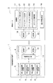
図2に示すように、無線カード2は、無線情報処理装置1が送信する各種の起動信号を受信する受信部19と、無線情報処理装置1へ応答信号を送信する送信部20と、無線カード2ごとに異なるカード固有の識別情報を記録した識別情報記録部18と、起動信号及び応答信号の送受信を制御する演算部17とを少なくとも有する。
【0021】
演算部17は、コマンドスロットを設定するコマンドスロット設定部21と、タイムスロットを設定するタイムスロット設定部22と、特定の起動信号を受信した回数を積算する積算部23と、無線情報処理装置1との通信期間において有効な特定情報(以下「コマンドID」という)を記憶/制御する特定情報制御部(以下「コマンドID制御部」という)24とを有する。ここで、「コマンドスロット」は0〜N(Nは0又は任意の自然数)の何れか1つの整数から成り、「タイムスロット」は0〜M(Mは0又は任意の自然数)の何れか1つの整数から成る。また、無線情報処理装置1が送信する「各種の起動信号」には、コマンドスロットを設定することを要求する第1の起動信号、識別情報を応答することを要求する第2の起動信号、タイムスロットを設定することを要求する第3の起動信号、及びコマンドIDを変更することを要求する第4の起動信号が含まれる。コマンドスロット設定部21は、第1の起動信号に従ってコマンドスロットを設定し、タイムスロット設定部22は、第3の起動信号に従ってタイムスロットを設定する。コマンドスロットは0〜Nの範囲内で設定され、タイムスロットは0〜Mの範囲内で設定される。積算部23は「特定の起動信号」として第2の起動信号を受信した回数を積算し、第2の起動信号を受信した回数がコマンドスロットと一致するか否かを判定する。
【0022】
送信部20は、第2の起動信号を受信した回数がコマンドスロットと一致する時に、若しくはタイムスロットより定まる応答時間区分において、無線情報処理装置1に対して識別情報を含む応答信号を送信する。なお、送信部20は、タイムスロット設定部22がタイムスロットを設定した時に、このタイムスロットより定まる応答時間区分において応答信号を送信する。
【0023】
以下、「積算部」の一例として、第2の起動信号を受信するたびにコマンドスロットを1づつ減算し、コマンドスロットが0になったか否かを判断するコマンドスロット減算部23について説明を続ける。
【0024】
一方、無線情報処理装置1において、カードリーダライタ4は、無線カード2に対して第1乃至第4の起動信号を送信する送信部14と、無線カード2が送信する識別情報を含む応答信号を受信する受信部15と、第1乃至第4の起動信号及び応答信号の送受信を制御する送受信制御部13とを有する。
【0025】
ホストコンピュータ5は、第1の起動信号を生成する第1の起動信号生成部7と、第2の起動信号を生成する第2の起動信号生成部8と、第3の起動信号を生成する第3の起動信号生成部9と、第4の起動信号を生成する第4の起動信号生成部10とを少なくとも有する。
【0026】
<無線情報処理装置の構成>
図3に示すように、カードリーダライタ4の送信部14は、送受信制御部13により制御される送信回路25と、送信回路25に接続されたループ状の送信アンテナコイル26とを有する。カードリーダライタ4の受信部15は、送受信制御部13により制御される受信回路27と、受信回路27に接続されたループ状の受信アンテナコイル28とを有する。
【0027】
ホストコンピュータ5は、第1乃至第4の起動信号の生成及び制御を司る演算部29と、データ記憶部30と、プログラム記憶部31と、入力装置32と、出力装置33とを有する。入力装置32はキーボード、マウス、ライトペンまたはフレキシブルディスク装置等で構成される。データ記憶部30及びプログラム記憶部31は、磁気テープ、磁気ドラム、磁気ディスク、光ディスク、光磁気ディスク、或いはROM、RAM等の半導体メモリー等を用いた記録部である。また出力装置33はディスプレイ装置やプリンタ装置などにより構成されている。演算部29、データ記憶部30およびプログラム記憶部31等はCPU、及びこのCPUに接続されたROM、RAM、磁気ディスク等の記憶装置を含む通常のコンピュータシステムで構成すればよい。演算部29で実行される各処理の入力データはデータ記憶部30に格納され、プログラム命令はプログラム記憶部31に記憶される。そしてこれらの入力データやプログラム命令は必要に応じてCPUに読み込まれ、演算処理が実行されるとともに、無線カード2からの応答信号の受信によって発生した数値情報などのデータはデータ記憶部30に格納される。
【0028】
演算部29は、第1乃至第4の起動信号生成部7〜10と、第1乃至第4の起動信号のうち何れの信号を送信するかを選択する起動信号選択部34と、コマンドスロット及びタイムスロットの設定範囲を決定するスロット設定範囲決定部35とを有する。スロット設定範囲決定部35は、コマンドスロットの設定範囲を示すNを、タイムスロットの設定範囲を示すMを夫々設定する。N及びMは、通信領域内に同時に存在し得る無線カード2の最大枚数等を参照して決定することができる。
【0029】
<起動信号の構成>
図4に示すように、無線情報処理装置が生成及び送信する起動信号51には、無線カード2に対する具体的な命令を示す各種コマンド58、通信領域内の複数の無線カード2を識別する為のカード識別情報72、及び各種コマンド付加電文等75が少なくとも含まれる。起動信号51を受信した無線カード2は、カード識別情報72の一致を条件として、各種コマンド58に示された命令を各種コマンド付加電文等75を参照して実行する。
【0030】
図5(a)に示すように、第1の起動信号52には、各種コマンド58としてアドレス応答コマンド59及びコマンドスロット(0〜N)設定コマンド60、カード識別情報72としてコマンドID73、及び各種コマンド付加電文等75としてコマンドスロット設定範囲(=N)76に関する情報が含まれる。
【0031】
図5(b)に示すように、第2の起動信号53には、各種コマンド58としてアドレス応答コマンド61及びコマンドスロット減算コマンド62、及びカード識別情報72としてコマンドID73が含まれる。
【0032】
図5(c)に示すように、第3の起動信号54には、各種コマンド58としてアドレス応答コマンド63及びタイムスロット(0〜M)設定コマンド64、カード識別情報72としてコマンドID73、及び各種コマンド付加電文等75としてタイムスロット設定範囲(=M)77に関する情報が含まれる。
【0033】
図5(d)に示すように、第4の起動信号55には、各種コマンド58としてコマンドID変更コマンド65、カード識別情報72として変更前コマンドID74及びカードアドレス46、及び各種コマンド付加電文等75として変更後コマンドID78が含まれる。なお、「カードアドレス」は、図2の識別情報記録部18に記録された識別情報の一例であり、その詳細については図6を参照して後述する。
【0034】
<無線カードの構成>
図2の受信部19及び送信部20は、図6の送受信部16に対応している。図6に示すように、送受信部16は、演算部17に接続された変復調回路37と、変復調回路37に接続されたループ状の送受信アンテナコイル36とを有する。
【0035】
コマンドスロット設定部21は、乱数を発生する第1の乱数発生器38と、第1の乱数発生器38によって発生した乱数を用いてコマンドスロットを設定するコマンドカウンタ39とを有する。コマンドスロット減算部23は、コマンドカウンタ39が設定したコマンドスロットを図5(b)の第2の起動信号53に従って1つづ減算する。
【0036】
タイムスロット設定部22は、乱数を発生する第2の乱数発生器40と、第2の乱数発生器40によって発生した乱数を用いてタイムスロットを設定するタイムカウンタ41と、タイムスロットより定まる応答時間区分を測定するタイマ42とを有する。タイムスロットより定まる応答時間区分を測定する為に、例えばタイマ42は、所定の時間間隔でタイムスロットを1づつ減算し、コマンドスロットが0になったか否かを判断すればよい。
【0037】
識別情報記録部18には、無線カード2が夫々有するカード固有の識別情報の一例として、カードアドレス46が記録されている。
【0038】
コマンドID制御部24は、コマンドIDを一時的に記録する特定情報記録部(以下「コマンドIDレジスタ」という)43と、コマンドIDレジスタ43に記録されたコマンドIDと図5(a)乃至(c)の第1乃至第3の起動信号52〜54に含まれるコマンドID73又は図5(d)の第4の起動信号55に含まれる変更前コマンドID74とを比較する特定情報比較部(以下「コマンドID比較部」という)44と、コマンドIDレジスタ43に記録されているコマンドIDを変更後コマンドID78へ変更する特定情報変更部(以下「コマンドID変更部」という)45とを更に有する。コマンドID変更部45は、コマンドIDレジスタ43に記録されたコマンドIDと変更前コマンドID74とが一致し、且つ識別情報記録部18に記録されたカードアドレス46と第4の起動信号55に含まれるカードアドレス46とが一致する時に、コマンドIDを変更する。
【0039】
コマンドスロット設定部21、コマンドスロット減算部23、及びタイムスロット設定部22は、コマンドIDレジスタ43に記録されているコマンドIDと第1乃至第3の起動信号52〜54に含まれるコマンドID73とが一致するときに、第1乃至第3の起動信号52〜54に従って各コマンド59〜64を実行する。
【0040】
図7に示すように、第1の乱数発生器38は、例えば8ビットデータからなる乱数47を発生させる。コマンドカウンタ39は、図5(a)のコマンドスロット設定範囲(=N)76に応じて必要なビット数、例えば4ビット分のデータを乱数47から抽出して、スロット(コマンドスロット)48を設定する。例えばN=15である場合、乱数47から4ビット分のデータを抽出してコマンドスロットを設定すればよい。カウンタスロットには、0〜15(=24−1)の内の任意の整数が無作為に設定されることになる。
【0041】
同様に、第2の乱数発生器40は、例えば8ビットデータからなる乱数47を発生させる。タイムカウンタ41は、図5(c)のタイムスロット設定範囲(=M)77に応じて必要なビット数、例えば4ビット分のデータを乱数47から抽出して、スロット(タイムスロット)48を設定する。4ビット分のデータを用いてタイムスロットを設定する場合、タイムスロットには、0〜15(=24−1)の内の任意の整数が設定されることになる。
【0042】
図8に示すように、第1及び第2の乱数発生器38、40は、直列に接続された複数のレジスタ49a〜49d及び排他論理和(XOR)回路50a、50bとを夫々有する。図8では、4ビットデータからなる乱数(47a、47b)を発生させる場合の第1及び第2の乱数発生器38、40の回路構成を示している。4つのレジスタ49a〜49dが直列に接続され、レジスタ49bとレジスタ49cの間にXOR回路50bが直列に挿入されている。レジスタ49aの入力端子はXOR回路50aの出力端子に接続され、XOR回路50aの入力端子にはカードアドレス46に関する情報が入力される。レジスタ49dの出力端子はXOR回路50a、50bの入力端子へそれぞれ帰還されている。レジスタ49a〜49dのクロック端子CK及びクリア端子CLRには、共通のクロック信号線及びクリア信号線が接続されている。レジスタ49a、XOR回路50b、レジスタ49c、及びレジスタ49dの各出力が、4ビットデータから成る乱数47a、47bを形成する。
【0043】
<無線カードの動作>
図9に示すように、S11段階において図5(a)の第1の起動信号52を受信した無線カード2は、先ず、S12段階において、図6のコマンドIDレジスタ43に記録されたコマンドIDと、第1の起動信号52に含まれるコマンドID73とが一致するか否かをコマンドID比較部44を用いて判断する。コマンドIDが一致する場合(S12段階においてYes)S13段階へ進み、コマンドスロット設定部21がコマンドスロット(0〜N)を設定する。即ち、無線カード2は、コマンドスロット(0〜N)設定コマンド60を実行する。この際、コマンドスロット設定範囲(=N)76が参照される。
【0044】
その後、S14段階において、設定したコマンドスロットが0であるか否かを判定する。コマンドスロットが0である場合(S14段階においてYes)S15段階へ進み、送受信部16が、無線情報処理装置1へカードアドレス46を含む応答信号を送信する。即ち、無線カード2が第1の起動信号52に含まれるアドレス応答コマンド59を実行する。そして、S16段階において第1の乱数発生器38が乱数を発生させて、無線カード2の動作が終了する。なお、コマンドIDが一致しない場合(S12段階においてNo)及びコマンドスロットが0でない場合(S14段階においてNo)、第1の起動信号52を受信した無線カード2の動作は終了する。
【0045】
図10に示すように、S21段階において図5(b)の第2の起動信号53を受信した無線カード2は、先ず、S22段階において、図6のコマンドIDレジスタ43に記録されたコマンドIDと、第2の起動信号53に含まれるコマンドID73とが一致するか否かをコマンドID比較部44を用いて判断する。コマンドIDが一致する場合(S22段階においてYes)S23段階へ進み、コマンドスロット減算部23はコマンドスロットが0より大きいか否かを判定する。即ち、コマンドスロットが1〜Nであるかそれとも0であるかを判定する。コマンドスロットが0より大きい場合(S23段階においてYes)S24段階へ進み、コマンドスロット減算部23がコマンドスロットを1減算する。即ち、コマンドスロットから1減算した値を新たにコマンドスロットと定める。
【0046】
その後、S25段階において、コマンドスロット減算部23がコマンドスロットが0であるか否かを判断する。コマンドスロットが0である場合(S25段階においてYes)S26段階へ進み、送受信部16は無線情報処理装置1へ応答信号を送信する。即ち、無線カード2が第2の起動信号53に含まれるアドレス応答コマンド61を実行する。そして、S27段階において第1の乱数発生器38が乱数を発生させて、無線カード2の動作が終了する。なお、コマンドIDが一致しない場合(S22段階においてNo)、S23段階でコマンドスロットが0である場合(S23段階においてNo)、及びS25段階でコマンドスロットが0でない場合(S25段階においてNo)、第2の起動信号53を受信した無線カード2の動作は終了する。
【0047】
このように、無線カード2は、第2の起動信号53を受信するたびにコマンドスロットを減算し、コマンドスロットが0になった時に応答信号を送信する。コマンドスロットが既に0である場合は減算を行わない。「コマンドスロットが既に0である場合」には、図9のS13段階においてコマンドスロットを0に設定した場合、或いはコマンドスロット(1〜N)よりも第2の起動信号53の受信回数を多い場合が含まれる。
【0048】
図11に示すように、S31段階において図5(c)の第3の起動信号54を受信した無線カード2は、先ず、S32段階において、図6のコマンドIDレジスタ43に記録されたコマンドIDと、第3の起動信号54に含まれるコマンドID73とが一致するか否かをコマンドID比較部44を用いて判断する。コマンドIDが一致する場合(S32段階においてYes)S33段階へ進み、タイムスロット設定部22がタイムスロット(0〜M)を設定する。即ち、無線カード2は、タイムスロット(0〜M)設定コマンド64を実行する。この際、タイムスロット設定範囲(=M)77が参照される。
【0049】
その後、S34段階において、設定したタイムスロットが0であるか否かを判定する。タイムスロットが0である場合(S34段階においてYes)S36段階へ進み、送受信部16は無線情報処理装置1へ応答信号を送信する。即ち、無線カード2が第3の起動信号54に含まれるアドレス応答コマンド63を実行する。タイムスロットが0でない場合(S34段階においてNo)S35段階へ進み、タイマ42がタイムスロットを1減算する。その後、S34段階に戻り、タイムスロットが0に成るまでタイマ42によるタイムスロットの減算を行う。応答信号を送信した後(S36段階の後)、S37段階において第2の乱数発生器40が乱数を発生させて、無線カード2の動作が終了する。なお、コマンドIDが一致しない場合(S32段階においてNo)、第3の起動信号54を受信した無線カード2の動作は終了する。
【0050】
図12に示すように、S41段階において図5(d)の第4の起動信号55を受信した無線カード2は、先ず、S42段階において、図6のコマンドIDレジスタ43に記録されたコマンドIDと、第4の起動信号55に含まれる変更前コマンドID74とが一致するか否かをコマンドID比較部44を用いて判断する。コマンドIDと変更前コマンドID74とが一致する場合(S42段階においてYes)S43段階へ進み、無線カード2は、識別情報記録部18に記録されたカードアドレス46と第4の起動信号55に含まれるカードアドレス46とが一致するか否かを判断する。カードアドレス46が一致する場合(S43段階においてYes)S44段階へ進み、コマンドID変換部45は、識別情報記録部18に記録されたカードアドレス46を変更後コマンドID78へ変更し、無線カード2の動作が終了する。なお、コマンドIDと変更前コマンドID74とが一致しない場合(S42段階においてNo)及びカードアドレス46が一致しない場合(S43段階においてNo)、第4の起動信号55を受信した無線カード2の動作は終了する。
【0051】
<無線情報処理システムの通信方法>
図13を参照して、本発明の第1の実施の形態に係る無線情報処理システムの通信方法を説明する。図13において、「R/W」はカードリーダライタ4を示し、「カード」は無線カード2を示す。また、通信領域内にある複数の無線カード2のコマンドIDの初期値は同じであるが、カードアドレス46は互いに異なる。
【0052】
(イ)まず、S101段階において、カードリーダライタ4が、通信領域内にある複数の無線カード2に対して、第1の起動信号52を送信する。第1の起動信号52には、コマンドID73及びコマンドスロット設定範囲(=N)76に関する情報が含まれている。
【0053】
(ロ)次に、S102段階において、無線カード2の送受信部16が第1の起動信号52を受信し、コマンドスロット設定部21がコマンドスロットを設定する。総ての無線カード2についてコマンドIDの初期値が同じである為、総ての無線カード2が第1の起動信号52に含まれるコマンドスロット設定設定コマンド60を実行する。
【0054】
(ハ)次に、S103段階において、コマンドスロット減算部23が、S102段階において設定したコマンドスロットが0であるか否かを判断する。コマンドロットが0であると判断した場合(S103段階においてYes)S106段階へ進む。コマンドスロットが0でないと判断した場合(S103段階においてNo)S104段階へ進む。なお、S103段階は、図9のS14段階に対応している。
【0055】
(ニ)次に、S104段階において、カードリーダライタ4が、第2の起動信号53を送信する。
【0056】
(ホ)次に、S105段階において、コマンドスロット減算部23が、第2の起動信号53を受信した回数がコマンドスロットと一致するか否かを判断する。S105段階は、図10のS23〜S25段階に対応している。第2の起動信号53を受信した回数がコマンドスロットと一致すると判断した場合(S105段階においてYes)S106段階へ進み、一致しないと判断した場合(S105段階においてNo)S109段階へ進む。
【0057】
(へ)次に、S106段階において、無線カード2が、カードアドレス46を含む応答信号を送信する。即ち、S103段階においてYesである場合に第1の起動信号52のアドレス応答コマンド59を実行し、S105段階においてYesである場合に第2の起動信号53のアドレス応答コマンド61を実行する。従って、「第1の起動信号52により設定されたコマンドスロットが0であること」が「第2の起動信号53を受信した回数が0であること」であると考えることで、S106段階は、第2の起動信号53を受信した回数がコマンドスロットと一致する場合に実行されるとみなすことが出来る。
【0058】
(ト)次に、S107段階において、カードリーダライタ4が応答信号を適切に受信した場合、その応答信号に含まれるカードアドレス46に基いて無線情報処理装置1が第4の起動信号55を生成し、カードリーダライタ4が第4の起動信号55を送信する。なお、カードリーダライタ4が応答信号を適切に受信するには、第1の起動信号52又は第2起動信号53の各1回の送信に対して、1つの無線カード2が応答信号を送信する必要がある。即ち、第1の起動信号52又は第2起動信号53の各1回の送信に対して、2以上の無線カード2が同時に応答信号をそれぞれ送信した場合、カードリーダライタ4はこれらの2以上の応答信号を適切に受信することが出来ない。
【0059】
(チ)次に、S108段階において、第4の起動信号55を受信した無線カード2の内、コマンドID及びカードアドレス46が一致する無線カード2が、コマンドIDを変更後コマンドID78へ変更する。これにより、応答信号がカードリーダライタ4によって適切に受信された無線カード2のコマンドIDが変更され、適切に受信されていない無線カード2との間で差別化することが出来る。
【0060】
(リ)次に、S109段階において、第2の起動信号53をN回送信したか否かを判断する。N回送信していない場合(S109段階においてNo)S104段階へ戻り、S104〜S109段階のループをN回繰り返す。N回送信した場合(S109段階においてYes)S110段階へ進む。
【0061】
(ヌ)次に、S110段階において、カードリーダライタ4が、第3の起動信号54を送信する。
【0062】
(ル)次に、S111段階において、第3の起動信号54を受信した無線カード2であって、応答信号がカードリーダライタ4によって適切に受信されていない無線カード2がタイムスロットを設定する。即ち、応答信号が適切に受信された無線カード2のコマンドIDは、S108段階において変更されている為、第3の起動信号54に含まれるコマンドIDと一致せず、第3の起動信号54に含まれるタイムスロット(0〜M)設定コマンド64を実行しない。
【0063】
(ヲ)最後に、S112段階において、タイムスロットを設定した無線カード2が、タイムスロットより定まる応答時間区分において、カードリーダライタ4に対して応答信号を送信する。なお、S112段階は、図11のS34〜S36段階に対応している。即ち、タイマ42がタイムスロットが0になるまで、所定の時間間隔でタイムスロット1づつ減算し(S34、S35)、タイムスロットが0になった時に無線カード2が応答信号を送信する(S36)。
【0064】
なお、S101〜S109段階から成る通信方式を「コマンドレスポンス方式」と呼び、S110〜S112段階から成る通信方式を「タイムレスポンス方式」と呼ぶ。また、S101〜S112段階から成る通信方式を、コマンドレスポンス方式からタイムレスポンス方式への「移行型通信方式」と呼ぶ。なお「コマンドレスポンス方式」に関連する発明が、未公開の先の出願(特願2001−365056号)において開示されている。
【0065】
次に、図14を参照して、10個の無線カード2に対して図13の通信方法を実施した場合について説明する。図14において、「A〜J」は無線カードの符号を示し、「矢印」はカードリーダライタ4が第1乃至第3の起動信号52〜54を送信する時を示し、▲1▼〜▲3▼はそれぞれ第1乃至第3の起動信号52〜54を示す。また、各無線カードA〜Jの凸部は応答信号の送信を示す。さらに、第1の起動信号52に含まれるコマンドスロット設定範囲がN=6であり、第3の起動信号54に含まれるタイムスロット設定範囲がM=5である。
【0066】
(イ)まず、第1の起動信号52がカードリーダライタ4から送信される。第1の起動信号52を受信した無線カードA〜Jが、0〜6(=N)の範囲でコマンドスロットを夫々設定する。図14に示すように無線カードA〜Jの内、コマンドスロット=0を設定した無線カードは無線カードCのみである。従って、無線カードCのみが応答信号を送信するため、カードリーダライタ4は無線カードCからの応答信号を適切に受信することが出来る。よって、無線カードCのコマンドIDは応答信号送信の後、変更される。
【0067】
(ロ)次に、第1回目の第2の起動信号53がカードリーダライタ4から送信される。第2の起動信号53を受信した無線カードA〜Jの内、第2の起動信号53の受信回数(=1)と同じコマンドスロットを設定した無線カードは、無線カードFと無線カードHである。従って、無線カードFと無線カードHが応答信号を同時に送信するため、カードリーダライタ4は無線カードFと無線カードHからの応答信号を適切に受信することが出来ない。よって、無線カードFと無線カードHのコマンドIDは変更されない。
【0068】
(ハ)次に、第2回目の第2の起動信号53を受信した無線カードA〜Jの内、第2の起動信号53の受信回数(=2)と同じコマンドスロットを設定した無線カードは、無線カードBのみである。従って、無線カードBのみが応答信号を送信するため、カードリーダライタ4は無線カードBからの応答信号を適切に受信することが出来る。よって、無線カードBのコマンドIDは応答信号返送の後、変更される。
【0069】
(ニ)次に、第3回目の第2の起動信号53を受信した無線カードA〜Jの内、第2の起動信号53の受信回数(=3)と同じコマンドスロットを設定した無線カードは、無線カードEと無線カードJである。従って、無線カードEと無線カードJが応答信号を同時に送信するため、カードリーダライタ4は無線カードEと無線カードJからの応答信号を適切に受信することが出来ない。よって、無線カードEと無線カードJのコマンドIDは変更されない。
【0070】
(ホ)以下同様にして、第4回目、第5回目、第6回目の第2の起動信号53がカードリーダライタ4から送信され、第4回目の第2の起動信号53に対して無線カードAのみが、第5回目の第2の起動信号53に対して無線カードDのみが、第6回目の第2の起動信号53に対して無線カードGと無線カードIが、夫々応答信号を送信する。従って、無線カードA及び無線カードDのコマンドIDは変更されるが、無線カードG及び無線カードIのコマンドIDは変更されない。
【0071】
(ヘ)第2の起動信号が6回送信された後、第3の起動信号54がカードリーダライタ4から送信される。第3の起動信号54を受信した無線カードA〜Jの内、応答信号が適切に受信されていない無線カードE〜Jが、0〜5(=M)の範囲でタイムスロットを夫々設定する。応答信号が適切に受信された無線カードA〜Dは、コマンドIDが変更されている為、第3の起動信号54のタイムスロット(0〜5)設定コマンド64を実行しない。
【0072】
(ト)無線カードE〜Jの内、タイムスロット=0を設定した無線カードは、無線カードEである。従って、無線カードEは、図11に示したS34−S35のループを1度も繰り返すことなく、応答信号を送信する(S36)。即ち、無線カードEは、タイムスロット(=0)より定まる最初の応答時間区分において応答信号を送信する。
【0073】
(チ)以下同様にして、タイムスロット=1〜5を設定した無線カードF〜Jは、図11に示したS34−S35のループを1〜5回繰り返した後、応答信号を夫々送信する(S36)。
【0074】
以上説明したように、本発明の第1の実施の形態によれば、通信領域内にある無線カード2の数が比較的多い場合、先ず、コマンドスロットを設定し、第2の起動信号53を必要回数送受信することで、複数の無線カード2から応答信号を適切に受信することができる。同時に、多数の無線カード2からの応答信号を受信する為に長い時間待つ必要がなく、短時間に効率的に応答信号を受信することができる。コマンドレスポンス方式を用いた後、応答信号が適切に受信されていない無線カードの数は比較的少ない。そこで、コマンドレスポンス方式において応答信号が適切に受信されなかった無線カードが、タイムスロットを設定し、所定の応答時間区分において応答信号を送信する。よって、応答時間の時間区分数が減り、全体の応答時間も短くて済む。従って、一度の第3の起動信号に対して、複数の無線カードからの応答信号を効率良く正確に受信することができる。
【0075】
このように、無線カードの数が多い場合に有効なコマンドレスポンス方式を用い、その後に、応答信号の適切な受信が行えなかった比較的数の少ない無線カードに対してタイムレスポンス方式を用いる。この「移行型通信方式」を用いることにより、通信対象物の数に依らず、応答信号の衝突を回避しつつ通信時間の短縮が実現される。
【0076】
(第2の実施の形態)
<無線情報処理装置の構成>
図16に示すように、本発明の第2の実施の形態に係る無線情報処理装置は、カードリーダライタ4と、ホストコンピュータ5とを有する。カードリーダライタ4は図3と同様な構成を有する。ホストコンピュータ5は、演算部29の構成を除き、図3と同様な構成を有する。
【0077】
演算部29は、第5の起動信号生成部11と、第6の起動信号部12と、第5及び第6の起動信号のうち何れの信号を送信するかを選択する起動信号選択部34と、スロット設定範囲決定部35とを有する。第5の起動信号生成部11は、コマンドスロット及びタイムスロットを設定することを要求する第5の起動信号を生成する。第6の起動信号生成部12は、タイムスロットを設定することを要求する第6の起動信号を生成する。
【0078】
<起動信号の構成>
図17(a)に示すように、第5の起動信号56には、各種コマンド58としてアドレス応答コマンド66、コマンドスロット(0〜N)設定コマンド67、及びタイムスロット(0〜M)設定コマンド68が含まれる。また、第5の起動信号56には、カード識別情報72としてコマンドID73、及び各種コマンド付加電文等75としてコマンドスロット設定範囲(=N)76及びタイムスロット設定範囲(=M)77に関する情報が含まれる。従って、第5の起動信号56は、図5(a)の第1の起動信号52と図5(c)の第3の起動信号54とを組み合わせたものであるといえる。
【0079】
図17(b)に示すように、第6の起動信号57には、各種コマンド58としてアドレス応答コマンド66、コマンドスロット減算コマンド70、及びタイムスロット(0〜M)設定コマンド68が含まれる。また、第6の起動信号57には、カード識別情報72としてコマンドID73、及び各種コマンド付加電文等75としてタイムスロット設定範囲(=M)77に関する情報が含まれる。従って、第6の起動信号57は、図5(b)の第2の起動信号53と図5(c)の第3の起動信号54とを組み合わせたものであるといえる。
【0080】
<無線カードの動作>
図18に示すように、S51段階において図17(a)の第5の起動信号56を受信した無線カード2は、先ず、S52段階において、図6のコマンドIDレジスタ43に記録されたコマンドIDと、第5の起動信号56に含まれるコマンドID73とが一致するか否かを判定する。コマンドIDが一致する場合(S52段階においてYes)S53段階へ進み、コマンドスロット(0〜N)及びタイムスロット(0〜M)を設定する。即ち、無線カード2は、コマンドスロット(0〜N)設定コマンド67及びタイムスロット(0〜M)設定コマンド68を実行する。この際、コマンドスロット設定範囲(=N)76及びタイムスロット設定範囲(=M)77が参照される。
【0081】
その後、S54段階において、設定したタイムスロットが0であるか否かを判定する。タイムスロットが0である場合(S54段階においてYes)S56段階へ進む。タイムスロットが0でない場合(S54段階においてNo)S55段階へ進み、タイムスロットを1減算する。その後、S54段階に戻り、タイムスロットが0に成るまでタイマ42によるタイムスロットの減算を行う。S56段階において、設定したコマンドスロットが0であるか否かを判定する。コマンドスロットが0である場合(S56段階においてYes)S57段階へ進み、無線カード2は無線情報処理装置1へカードアドレス46を含む応答信号を送信する。そして、S58段階において第1の乱数発生器38が乱数を発生させて、無線カード2の動作が終了する。なお、コマンドIDが一致しない場合(S52段階においてNo)及びコマンドスロットが0でない場合(S56段階においてNo)、第5の起動信号56を受信した無線カード2の動作は終了する。
【0082】
図19に示すように、S61段階において図17(b)の第6の起動信号57を受信した無線カード2は、先ず、S62段階において、図6のコマンドIDレジスタ43に記録されたコマンドIDと、第6の起動信号57に含まれるコマンドID73とが一致するか否かを判定する。コマンドIDが一致する場合(S62段階においてYes)S63段階へ進み、タイムスロット(0〜M)を設定する。即ち、無線カード2は、第6の起動信号57のタイムスロット(0〜M)設定コマンド71を実行する。この際、タイムスロット設定範囲(=M)77が参照される。その後、S64段階において、設定したタイムスロットが0であるか否かを判定する。タイムスロットが0である場合(S64段階においてYes)S66段階へ進む。タイムスロットが0でない場合(S64段階においてNo)S65段階へ進み、タイムスロットを1減算する。
【0083】
その後、S64段階に戻り、タイムスロットが0になるまでタイマ42によるタイムスロットの減算を行う。S66段階において、コマンドスロットが0より大きいか否かを判定する。コマンドスロットが0より大きい場合(S66段階においてYes)S67段階へ進み、コマンドスロットを1減算する。その後、S68段階においてコマンドスロットが0であるか否かを判断する。コマンドスロットが0である場合(S68段階においてYes)S69段階へ進み、無線カード2は無線情報処理装置1へ応答信号を送信する。そして、S70段階において第1乃至第2の乱数発生器38,40が乱数を発生させて、無線カード2の動作が終了する。
【0084】
なお、コマンドIDが一致しない場合(S62段階においてNo)、S66段階でコマンドスロットが0である場合(S66段階においてNo)、及びS68段階でコマンドスロットが0でない場合(S68段階においてNo)、第6の起動信号57を受信した無線カード2の動作は終了する。このように、無線カード2は、第6の起動信号57を受信するたびにコマンドスロットを減算し、コマンドスロット及びタイムスロットが共に零になった時に応答信号を送信する。
【0085】
<無線情報処理システムの通信方法>
図20を参照して、本発明の第2の実施の形態に係る無線情報処理システムの通信方法を説明する。図20において、「R/W」はカードリーダライタ4を示し、「カード」は無線カード2を示す。また、通信領域内にある複数の無線カード2のコマンドIDの初期値は同じであるが、カードアドレス46は互いに異なる。
【0086】
(イ)まず、S201段階において、カードリーダライタ4が、通信領域内にある複数の無線カード2に対して、第5の起動信号56を送信する。第5の起動信号56には、コマンドID73、コマンドスロット設定範囲(=N)76、及びタイムスロット設定範囲(=M)77に関する情報が含まれている。
【0087】
(ロ)次に、S202段階において、無線カード2の送受信部16が第5の起動信号56を受信し、コマンドスロット設定部21がコマンドスロットを設定し、タイムスロット設定部22がタイムスロットを設定する。総ての無線カード2についてコマンドIDの初期値が同じである為、総ての無線カード2が第5の起動信号56に含まれるコマンドスロット設定設定コマンド67及びタイムスロット設定設定コマンド68を実行する。
【0088】
(ハ)次に、S203段階において、コマンドスロット減算部23が、S202段階において設定したコマンドスロットが0より大きいか否かを判定する。コマンドスロットが0より大きい場合(S203段階においてYes)S204段階へ進み、コマンドスロットが0である場合(S203段階においてNo)S207段階へ進む。なお、S203段階は、図18のS56段階に対応している。
【0089】
(ニ)次に、S204段階において、カードリーダライタ4が、第6の起動信号57を送信する。
【0090】
(ホ)次に、S205段階において、無線カード2の送受信部16が第6の起動信号57を受信し、タイムスロット設定部22がタイムスロットを設定する。
【0091】
(へ)次に、S206段階において、コマンドスロット減算部23が、第6の起動信号57を受信した回数がコマンドスロットと一致するか否かを判断する。S206段階は、図19のS66〜S68段階に対応している。第6の起動信号57を受信した回数がコマンドスロットと一致すると判断した場合(S206段階においてYes)S207段階へ進み、一致しないと判断した場合(S206段階においてNo)S208段階へ進む。
【0092】
(ト)次に、S207段階において、無線カード2の送受信部16が、タイムスロットより定まる応答時間区分においてカードアドレス46を含む応答信号を送信する。即ち、S203段階においてNoである場合に第5の起動信号56のアドレス応答コマンド66を実行し、S206段階においてYesである場合に第6の起動信号57のアドレス応答コマンド67を実行する。
【0093】
(チ)最後に、S208段階において、第6の起動信号57をN回送信したか否かを判断する。N回送信していない場合(S208段階においてNo)S204段階へ戻り、S204〜S208段階のループをN回繰り返す。N回送信した場合(S208段階においてYes)、終了する。
【0094】
なお、S201〜S208段階から成る通信方式を、コマンドレスポンス方式及びタイムレスポンス方式の「混在型通信方式」と呼ぶ。
【0095】
次に、図21を参照して、9個の無線カード2に対して図20の混在型通信方式を実施した場合について説明する。図21において、「A〜I」は無線カードの符号を示し、「矢印」はカードリーダライタ4が第5又は第6の起動信号56、57を送信する時を示す。また、各無線カードA〜Iの斜線部は応答信号の送信を示す。また、第5及び第6の起動信号56、57に含まれるコマンドスロット設定範囲がN=4であり、タイムスロット設定範囲がM=2である。
【0096】
(イ)まず、第1回目の第5の起動信号56がカードリーダライタ4から送信される。なお、第1回目の第5の起動信号56には、コマンドスロット設定範囲(N=0)76、タイムスロット設定範囲(M=0)77に関する情報が含まれている。第1回目の第5の起動信号56を受信した無線カードA〜Iが、コマンドスロット=0及びタイムスロット=0を夫々設定する。従って、図14に示すように総ての無線カードA〜Iが同時に応答信号を送信し、第1及び第2の乱数発生器38、40が乱数を発生させる。このようにして、コマンドスロット及びタイムスロットを初期化(N=0、M=0)することが出来、コマンドスロット及びタイムスロットを設定する為の乱数を用意することができる。
【0097】
(ロ)次に、第2回目の第5の起動信号56がカードリーダライタ4から送信される。なお、第2回目の第5の起動信号56には、コマンドスロット設定範囲(N=4)76、タイムスロット設定範囲(M=2)77に関する情報が含まれている。第2回目の第5の起動信号56を受信した無線カードA〜Iが、0〜4の範囲内でコマンドスロットを夫々設定し、0〜2の範囲内でタイムスロットを夫々設定する。
【0098】
(ハ)図12に示すように、コマンドスロットを0に設定した無線カードD及び無線カードGは、第6の起動信号57を受信した回数(=0)がコマンドスロットと一致する為、タイムスロットから定まる応答時間区分において応答信号をそれぞれ送信する。なお、無線カードDはタイムスロット=2を設定し、無線カードGはタイムスロット=0を設定している為、無線カードD及び無線カードGは、互いに異なる応答時間区分において応答信号をそれぞれ送信する。従って、無線カードD及び無線カードGが応答信号を同時に送信することがなく、カードリーダライタ4は無線カードD及び無線カードGからの応答信号を適切に受信することができる。よって、無線カードD及び無線カードGのコマンドIDは応答信号送信の後、変更される。なお、無線カードA〜C、E、F、H、Iはコマンドスロットを0以外の自然数に設定したため、タイムスロットから定まる応答時間区分においても応答信号を送信することはない。
【0099】
(ニ)次に、第1回目の第6の起動信号57がカードリーダライタ4から送信される。なお、第1回目の第6の起動信号57には、第2回目の第5の起動信号56と同様に、コマンドスロット設定範囲(N=4)76、タイムスロット設定範囲(M=2)77に関する情報が含まれている。
【0100】
(ホ)第1回目の第6の起動信号57を受信した無線カードA〜Jの内、応答信号を送信していない無線カードA〜C、E、F、H、Iが、0〜2(=M)の範囲でタイムスロットを夫々設定する。応答信号が適切に受信された無線カードD及び無線カードGは、コマンドIDが変更されている為、第6の起動信号57のタイムスロット(0〜2)設定コマンド71を実行しない。
【0101】
(ヘ)また、無線カードC及び無線カードIはコマンドスロットを1に設定している。従って、第6の起動信号57を受信した回数(=1)がコマンドスロットと一致する為、無線カードC及び無線カードIはタイムスロットから定まる応答時間区分において応答信号をそれぞれ送信する。なお、無線カードCはタイムスロット=0を設定し、無線カードIはタイムスロット=2を設定している為、無線カードC及び無線カードIは、互いに異なる応答時間区分において応答信号をそれぞれ送信する。従って、前述したように、無線カードC及び無線カードIが応答信号を同時に送信することがなく、カードリーダライタ4は無線カードC及び無線カードIからの応答信号を適切に受信することができる。よって、無線カードC及び無線カードIのコマンドIDは応答信号送信の後、変更される。
【0102】
(ト)以下同様にして、第2回目、第3回目、第4回目の第6の起動信号57がカードリーダライタ4から送信される。そして、第2回目の第6の起動信号57に対して無線カードB及び無線カードFが、第3回目の第6の起動信号57に対して無線カードEが、第4回目の第6の起動信号57に対して無線カードA及び無線カードHが、タイムスロットから定まる応答時間区分において応答信号を送信する。
【0103】
なお、図21においては、第6の起動信号57を受信するたびに無線カードA〜Iのコマンドスロットを1づつ減算している。この場合、減算した結果コマンドスロットが0になった時を、第6の起動信号57を受信した回数がコマンドスロットと一致する時とみなしている。
【0104】
以上説明したように、本発明の第2の実施の形態によれば、無線カード2は、第6の起動信号57を受信した回数がコマンドスロットと一致する時に、タイムスロットより定まる応答時間区分において、応答信号を送信する。2以上の無線カード2が同じコマンドスロットを設定した場合であっても、タイムスロットが異なれば、応答タイミングに時差を生じ、応答信号の衝突が回避される。即ち、「混在型通信方式」を用いることで、コマンドスロット及びタイムスロットによる2つの応答条件が揃った無線カード2のみが応答信号を送信することができる。よって、応答信号が衝突する確率が低下し、通信時間が短縮される。
【0105】
(第2の実施の形態の変形例)
図20に示した「混在型通信方式」において、第5及び第6の起動信号56、57に含まれるコマンドスロット設定範囲(=N)及びコマンドスロット設定範囲(=M)を所定の値にすることで、様々な通信方式を実現することができる。
【0106】
例えば、図22(a)に示すように、第5及び第6の起動信号56、57において、コマンドスロット設定範囲(=N)を0以外の値とし、タイムスロット設定範囲(=M)を0とする。図22(a)に示す第5及び第6の起動信号56、57を用いて図20に示した通信方式を実施した場合、S202段階及びS205段階において、無線カード2はコマンドスロットを1〜Nの範囲で設定し、タイムスロットを0に設定する。S207段階において、無線カード2は、応答時間区分に依らず応答信号を送信する。即ち、図13に示す「コマンドレスポンス方式」と実質的に同一の通信方式を実施することが出来る。
【0107】
また、図22(b)に示すように、第5の起動信号56において、コマンドスロット設定範囲(=N)を0とし、タイムスロット設定範囲(=M)を0以外の値とする。図22(b)に示す第5の起動信号56を用いて図20に示した通信方式を実施した場合、S202段階において、無線カード2はコマンドスロットを0に設定し、タイムスロットを1〜Mの範囲で設定する。S203段階において総ての無線カード2がNoを選択してS207段階へ進む。即ち、図13に示す「タイムレスポンス方式」と実質的に同一の通信方式を実施することが出来る。
【0108】
このように、第5及び第6の起動信号56、57において、コマンドスロット設定範囲(=N)及びコマンドスロット設定範囲(=M)を特定することで、コマンドレスポンス方式、タイムレスポンス方式、移行型通信方式、及び混在型通信方式を自由に切り替えて実施することができる。
【0109】
(その他の実施の形態)
上記のように、本発明は、第1及び第2の実施の形態によって記載したが、この開示の一部をなす論述及び図面はこの発明を限定するものであると理解すべきではない。この開示から当業者には様々な代替実施の形態、実施例及び運用技術が明らかとなろう。
【0110】
本発明の第1及び第2の実施の形態においては、無線カード2が2つの乱数発生器38、40を有する場合について説明したが、本発明の実施形態はこれに限定されるものでは無い。1つ又は3つ以上であっても構わない。例えば図15に示すように、コマンドカウンタ39及びタイムカウンタ41が1つの乱数発生器79を共有しても構わない。図7に示した第1及び第2の乱数発生器38、40の8ビットデータを、乱数発生器79では10ビットデータに増やす。そして、コマンドカウンタ39が10ビットデータの上8桁を用いてコマンドスロットを設定し、タイムカウンタ41が10ビットデータの下8桁を用いてタイムスロットを設定する。乱数発生器を構成する回路の形成領域の縮小化を図ることができる。
【0111】
本発明の第1及び第2の実施の形態においては、コマンドIDを用いて複数の無線カード2を識別していたが、本発明はこれに限定されるものでは無い。「プロトコル」を用いてコマンドIDに関係なく強制的に図4の起動信号51に含まれる各種コマンド58に対して無線カード2を応答させない方法を用いることができる。以下、プロトコル方式を具体的に示す。
【0112】
カードリーダライタ4は、コマンドレスポンス方式、タイムレスポンス方式、移行型通信方式、混在型通信方式など様々な通信方式によってカードアドレス46を入手する。カードリーダライタ4は、入手したカードアドレス46を用いて、特定の無線カード2に対して各種コマンド58に対して無応答となるコマンド(ATQキャンセルコマンド)を送信する。カードリーダライタ4と通信可能な領域内にある総ての無線カード2はこの無応答となるコマンドを受信するが、カードアドレス46が一致する無線カード2のみが、それ以後の起動信号51に含まれる各種コマンド58に対して無応答となる。コマンドIDを用いた場合、変更後であっても図5(d)の変更後コマンドID78に一致すれば各種コマンド58を実行することができる。しかし、プロトコルを用いた場合、無線カード2をリセットするまでその無線カード2は一切のコマンドを実行することは無い。
【0113】
このように、本発明はここでは記載していない様々な実施の形態等を包含するということを理解すべきである。したがって、本発明はこの開示から妥当な特許請求の範囲に係る発明特定事項によってのみ限定されるものである。
【0114】
【発明の効果】
以上説明したように、本発明によれば、通信対象物の数に依らず、応答信号の衝突を回避しつつ通信時間の短縮が可能な無線情報処理システム、無線情報記録媒体、無線情報処理装置、及び無線情報処理システムの通信方法を提供することができる。
【図面の簡単な説明】
【図1】本発明の第1の実施の形態に係る無線情報処理システムの全体構成を示すブロック図である。
【図2】図1に示した無線情報処理システムの詳細な構成を示すブロック図である。
【図3】図2に示した無線情報処理装置の詳細な構成を示すブロック図である。
【図4】無線情報処理装置が生成及び送信する起動信号の一般的な構成を示すブロック図である。
【図5】図5(a)乃至(d)は、第1乃至第4の起動信号の具体的な構成を示すブロック図である。
【図6】図2に示した無線カードの詳細な構成を示すブロック図である。
【図7】図6に示した第1の乱数発生器とコマンドカウンタとの関係及び第2の乱数発生器とタイムカウンタとの関係を示すブロック図である。
【図8】図7に示した第1及び第2の乱数発生器の具体的な回路構成の一例を示すブロック図である。
【図9】第1の起動信号を受信した無線カードの動作を示すフローチャートである。
【図10】第2の起動信号を受信した無線カードの動作を示すフローチャートである。
【図11】第3の起動信号を受信した無線カードの動作を示すフローチャートである。
【図12】第4の起動信号を受信した無線カードの動作を示すフローチャートである。
【図13】本発明の第1の実施の形態に係る無線情報処理システムの通信方法を示すフローチャートである。
【図14】図13に示した第1の実施の形態に係る無線情報処理システムの通信方法を用いた一実施例を示す図である。
【図15】1つの乱数発生器からコマンドスロット及びタイムスロットを設定する無線カードの構成を示すブロック図である。
【図16】本発明の第2の実施の形態に係る無線情報処理装置の詳細な構成を示すブロック図である。
【図17】図17(a)及び(b)は、第5及び第6の起動信号の具体的な構成を示すブロック図である。
【図18】第5の起動信号を受信した無線カードの動作を示すフローチャートである。
【図19】第6の起動信号を受信した無線カードの動作を示すフローチャートである。
【図20】本発明の第2の実施の形態に係る無線情報処理システムの通信方法を示すフローチャートである。
【図21】図20に示した第2の実施の形態に係る無線情報処理システムの通信方法を用いた一実施例を示す図である。
【図22】図22(a)及び(b)は、第2の実施の形態の変形例に係る無線情報処理システムを説明する為のブロック図である。
【符号の説明】
1 無線情報処理装置
2 無線カード
3 無線通信
4 カードリーダライタ
5 ホストコンピュータ
6 通信領域
7 第1の起動信号生成部
8 第2の起動信号生成部
9 第3の起動信号生成部
10 第4の起動信号生成部
11 第5の起動信号生成部
12 第6の起動信号生成部
13 送受信制御部
14、20 送信部
15、19 受信部
16 送受信部
17、29 演算部
18 識別情報記録部
21 コマンドスロット設定部
22 タイムスロット設定部
23 コマンドスロット減算部
24 コマンドID制御部
34 起動信号選択部
35 スロット設定範囲決定部
38 第1の乱数発生器
39 コマンドカウンタ
40 第2の乱数発生器
41 タイムカウンタ
42 タイマ
43 コマンドIDレジスタ
44 コマンドID比較部
45 コマンドID変更部
46 カードアドレス
52 第1の起動信号
53 第2の起動信号
54 第3の起動信号
55 第4の起動信号
56 第5の起動信号
57 第6の起動信号
79 乱数発生器[0001]
TECHNICAL FIELD OF THE INVENTION
The present invention relates to a wireless information processing system, a wireless information recording medium, a wireless information processing device, and a communication method of a wireless information processing system, and more particularly, to wireless communication between a plurality of wireless information recording media and a wireless information processing device. The present invention relates to a communication system of wireless information processing for transmitting and receiving signals.
[0002]
[Prior art]
2. Description of the Related Art Conventionally, there has been a wireless card system including a wireless information recording medium such as a plurality of wireless cards and a wireless information processing apparatus having a card reader / writer for transmitting and receiving signals to and from these wireless cards by wireless communication. In this wireless card system, a communication method called “multi-read method” has been established in which a card reader / writer receives response signals transmitted by a plurality of wireless cards at once. In recent years, for example, Japanese Unexamined Patent Application Publication No. 10-222622 (first prior art) and the like have proposed various improvements and related technologies related to the multi-read system.
[0003]
The first related art is characterized by providing a time difference for transmitting a response signal for each wireless card in order to accurately receive a plurality of response signals at once. That is, the number of time segments corresponding to the number of cards is set for the response time required to receive response signals from a plurality of wireless cards at one time, and the response signals are assigned in response time intervals assigned by each wireless card. Send each one. The collision avoidance and accurate reception of the response signal can be performed, and the communication time can be reduced.
[0004]
Specifically, a case will be described in which the wireless information processing apparatus transmits an activation signal requesting a response of a card address to a plurality of wireless cards in a communicable area (communication area). The wireless information processing device transmits, for example, the number of time divisions of the response time including the maximum number of wireless cards that can exist simultaneously in the communication area together with the activation signal. The plurality of wireless cards receiving the activation signal generate random numbers, select one of the response time sections, and transmit a response signal including a card address or the like in the response time section to the card reader / writer. The probability of multiple wireless cards transmitting response signals in different response time segments is increased, and response signal collisions are avoided.
[0005]
[Problems to be solved by the invention]
The communication system according to the first related art has the following advantages and disadvantages depending on the number of wireless cards. The wireless information processing device that has once transmitted the activation signal needs to wait for a response from a plurality of wireless cards for a certain response time thereafter. If the maximum number of wireless cards that can be simultaneously present in the communication area is small, the number of response time segments is reduced, and the overall response time can be shortened. Therefore, it is possible to efficiently and accurately receive response signals from a plurality of wireless cards in response to one activation signal.
[0006]
However, when the number of wireless cards to be communicated is large, the wireless information processing apparatus must set a large number of time divisions, send a start signal, and wait for a long response time for a response from the wireless card. If the number of time sections is set small to shorten the response time, the probability of collision of response signals increases, making it difficult to receive accurate response signals.
[0007]
As described above, there is an upper limit to the number of wireless cards in which the communication method according to the first related art can function effectively, and appropriate wireless communication becomes difficult according to the increase or decrease in the number of wireless cards. There is a need for a new multi-read system that overcomes the disadvantages while taking advantage of the communication system according to the first prior art.
[0008]
The present invention has been made in order to solve such problems of the related art, and an object of the present invention is to provide a wireless communication system capable of reducing a communication time while avoiding collision of response signals regardless of the number of communication objects. An object of the present invention is to provide an information processing system, a wireless information recording medium, a wireless information processing device, and a communication method of the wireless information processing system.
[0009]
[Means for Solving the Problems]
To achieve the above object, a first feature of the present invention is a wireless information processing system having a wireless information processing device and a wireless information recording medium, wherein the wireless information processing device has a wireless information having unique identification information. A first activation signal generation unit that generates a first activation signal requesting that a command slot be set in the recording medium; and a second activation signal generation unit that requests the wireless information recording medium to respond with identification information. A second activation signal generation unit for generating an activation signal, a third activation signal generation unit for generating a third activation signal requesting that a time slot be set for the wireless information recording medium, A transmission unit that transmits first to third activation signals to a plurality of wireless information recording media in the wireless communication device, and a reception unit that receives a response signal including identification information transmitted by the wireless information recording medium, Information recording medium Is an identification information recording unit in which identification information is recorded, a receiving unit that receives the first to third activation signals, a command slot setting unit that sets a command slot, and the number of times that the second activation signal is received. An integrator for integrating, a transmitter for transmitting a response signal in a response time interval determined by the time slot when the number of times the second activation signal is received matches the command slot or when a time slot is set; And a time slot setting unit for setting a time slot when the information is not properly received by the wireless information processing apparatus.
[0010]
According to the first aspect of the present invention, the wireless information recording medium is provided in a response time section determined by the time slot when the number of times the second start signal is received matches the command slot or when the time slot is set. Send a response signal. That is, the identification information is responded when the response condition by the command slot or the response condition by the time slot is prepared. When the number of wireless information recording media in the communication area is relatively large, first, a response signal is transmitted and received by the command slot, and then, when the number of wireless information recording media is relatively small, the response by the time slot is performed. Sends and receives signals.
[0011]
A second feature of the present invention is a wireless information processing system having a wireless information processing device and a wireless information recording medium, wherein the wireless information processing device is a wireless information processing device according to the first feature of the present invention, The wireless information recording medium includes an identification information recording unit on which identification information is recorded, a receiving unit that receives first to third activation signals, a command slot setting unit that sets a command slot, and a second activation signal. An accumulating unit for accumulating the number of times received, a time slot setting unit for setting a time slot, and a wireless information processing unit in a response time section determined by the time slot when the number of times the second activation signal is received matches the command slot. And a transmitting unit for transmitting a response signal to the device.
[0012]
According to the second aspect of the present invention, when the number of times the second activation signal is received matches the command slot, the wireless information recording medium transmits the response signal in a response time section determined by the time slot.
[0013]
A third feature of the present invention resides in that an identification information recording unit in which unique identification information is recorded, a first activation signal transmitted by the wireless information processing device requesting setting of a command slot, and a response to the identification information. Receiving a second activation signal requesting to perform an operation, a third activation signal requesting to set a time slot, a command slot setting unit for setting a command slot, and a second activation signal. An accumulating unit for accumulating the number of receptions, and when the number of times the second activation signal is received coincides with the command slot, or when a time slot is set, in a response time section determined by the time slot, A transmission unit for transmitting a response signal including identification information, and setting a time slot when the response signal is not properly received by the wireless information processing device. It is that it is wireless information recording medium comprising a that time slot setting section.
[0014]
A fourth feature of the present invention is a time slot setting unit that includes an identification information recording unit, a receiving unit, a command slot setting unit, and an integrating unit according to the third feature of the present invention, and sets a time slot. And a transmission unit for transmitting a response signal including identification information to the wireless information processing device in a response time interval determined by the time slot when the number of times the activation signal has been received matches the command slot. It is a recording medium.
[0015]
A fifth feature of the present invention is that a first activation signal generation unit that generates a first activation signal requesting that a command slot be set for a wireless information recording medium having unique identification information; A second activation signal generation unit for generating a second activation signal for requesting a response of the identification information to the recording medium; and a third activation request for setting a time slot for the wireless information recording medium. A third activation signal generation unit that generates an activation signal; a transmission unit that transmits first to third activation signals to a plurality of wireless information recording media in the communication area; and a second activation signal that is received. A response signal including identification information transmitted by the wireless information recording medium whose number of times coincides with the command slot, and a receiving unit receiving a response signal transmitted by the wireless information recording medium in a response time interval determined by the time slot. Is that a wireless information processing apparatus that Bei.
[0016]
A sixth feature of the present invention resides in that the wireless information processing apparatus sets a command slot composed of any one of integers from 0 to N (N is 0 or an arbitrary natural number) for a plurality of wireless information recording media in the communication area. The wireless information recording medium in which the set command slot and the number of times the response instruction transmitted by the wireless information processing device has been received matches the unique identification information of the wireless information recording medium, The wireless information processing device instructed to set a time slot consisting of any one of integers from 0 to M (M is 0 or an arbitrary natural number) for a plurality of wireless information recording media, and returned identification information. A wireless information recording medium that has not been properly received by the wireless information processing apparatus may cause the wireless information processing system to respond to the identification information in a response time section determined by the set time slot. It is that it is a method.
[0017]
A seventh feature of the present invention resides in that the wireless information processing apparatus sets a command slot composed of an integer of any one of 0 to N (N is 0 or an arbitrary natural number) for a plurality of wireless information recording media in a communication area. And a time slot consisting of any one of 0 to M (M is 0 or an arbitrary natural number) is set, and the number of times the set command slot and the number of times a response command transmitted by the wireless information processing apparatus has been received is The matching wireless information recording medium is a communication method of a wireless information processing system that responds with unique identification information of the wireless information recording medium in a response time section determined from a set time slot.
[0018]
BEST MODE FOR CARRYING OUT THE INVENTION
Embodiments of the present invention will be described below with reference to the drawings. In the description of the drawings, the same or similar parts are denoted by the same or similar reference numerals.
[0019]
(First Embodiment)
<Configuration of wireless information processing system>
As shown in FIG. 1, a wireless information processing system according to a first embodiment of the present invention includes a plurality of wireless information recording media, and wireless information for transmitting and receiving signals via the wireless information recording medium and the
[0020]
As shown in FIG. 2, the
[0021]
The
[0022]
The
[0023]
Hereinafter, as an example of the “integrator”, the description of the
[0024]
On the other hand, in the wireless
[0025]
The
[0026]
<Configuration of wireless information processing device>
As shown in FIG. 3, the
[0027]
The
[0028]
The
[0029]
<Configuration of start signal>
As shown in FIG. 4, the
[0030]
As shown in FIG. 5A, the
[0031]
As shown in FIG. 5B, the
[0032]
As shown in FIG. 5C, the
[0033]
As shown in FIG. 5D, the
[0034]
<Configuration of wireless card>
The receiving
[0035]
The command
[0036]
The time
[0037]
In the identification
[0038]
The command
[0039]
The command
[0040]
As shown in FIG. 7, the first
[0041]
Similarly, the second
[0042]
As shown in FIG. 8, the first and second
[0043]
<Operation of wireless card>
As shown in FIG. 9, the
[0044]
Thereafter, in step S14, it is determined whether the set command slot is 0. If the command slot is 0 (Yes in step S14), the process proceeds to step S15, where the transmitting / receiving
[0045]
As shown in FIG. 10, the
[0046]
Thereafter, in step S25, the command
[0047]
As described above, the
[0048]
As shown in FIG. 11, the
[0049]
Thereafter, in step S34, it is determined whether or not the set time slot is 0. If the time slot is 0 (Yes in step S34), the process proceeds to step S36, where the transmitting / receiving
[0050]
As shown in FIG. 12, the
[0051]
<Communication method of wireless information processing system>
A communication method of the wireless information processing system according to the first embodiment of the present invention will be described with reference to FIG. In FIG. 13, “R / W” indicates the card reader /
[0052]
(A) First, in step S101, the card reader /
[0053]
(B) Next, in step S102, the transmitting / receiving
[0054]
(C) Next, in step S103, the command
[0055]
(D) Next, in step S104, the card reader /
[0056]
(E) Next, in step S105, the command
[0057]
(F) Next, in step S106, the
[0058]
(G) Next, in step S107, when the card reader /
[0059]
(H) Next, in step S108, among the
[0060]
(I) Next, in step S109, it is determined whether the
[0061]
(G) Next, in step S110, the card reader /
[0062]
(R) Next, in step S111, the
[0063]
(ヲ) Finally, in step S112, the
[0064]
Note that the communication method including the steps S101 to S109 is referred to as a “command response method”, and the communication method including the steps S110 to S112 is referred to as a “time response method”. Further, the communication method including the steps S101 to S112 is referred to as a "transition communication method" from the command response method to the time response method. An invention relating to the "command response method" is disclosed in an unpublished earlier application (Japanese Patent Application No. 2001-365056).
[0065]
Next, a case where the communication method of FIG. 13 is applied to ten
[0066]
(A) First, the
[0067]
(B) Next, the first
[0068]
(C) Next, among the wireless cards A to J that have received the
[0069]
(D) Next, among the wireless cards A to J that have received the
[0070]
(E) Similarly, the fourth, fifth, and sixth second activation signals 53 are transmitted from the card reader /
[0071]
(F) After the second activation signal is transmitted six times, the
[0072]
(G) Among the wireless cards E to J, the wireless card in which the time slot = 0 is set is the wireless card E. Therefore, the wireless card E transmits a response signal without repeating the loop of S34-S35 shown in FIG. 11 (S36). That is, the wireless card E transmits a response signal in the first response time section determined from the time slot (= 0).
[0073]
(H) Similarly, the wireless cards F to J in which the time slots = 1 to 5 are set repeat the loop of S34 to S35 shown in FIG. 11 one to five times and then transmit response signals respectively ( S36).
[0074]
As described above, according to the first embodiment of the present invention, when the number of
[0075]
As described above, the command response method that is effective when the number of wireless cards is large is used, and thereafter, the time response method is used for a relatively small number of wireless cards that have failed to properly receive a response signal. By using the “transitional communication method”, the communication time can be reduced while avoiding collision of response signals, regardless of the number of communication objects.
[0076]
(Second embodiment)
<Configuration of wireless information processing device>
As shown in FIG. 16, the wireless information processing apparatus according to the second embodiment of the present invention has a card reader /
[0077]
The
[0078]
<Configuration of start signal>
As shown in FIG. 17A, the
[0079]
As shown in FIG. 17B, the
[0080]
<Operation of wireless card>
As shown in FIG. 18, the
[0081]
Thereafter, in step S54, it is determined whether or not the set time slot is 0. If the time slot is 0 (Yes in step S54), the process proceeds to step S56. If the time slot is not 0 (No in step S54), the process proceeds to step S55, where 1 is subtracted from the time slot. Thereafter, the process returns to step S54, and the time slot is subtracted by the
[0082]
As shown in FIG. 19, the
[0083]
Thereafter, the process returns to step S64, and the time slot is subtracted by the
[0084]
If the command IDs do not match (No in step S62), if the command slot is 0 in step S66 (No in step S66), and if the command slot is not 0 in step S68 (No in step S68), The operation of the
[0085]
<Communication method of wireless information processing system>
Referring to FIG. 20, a communication method of the wireless information processing system according to the second embodiment of the present invention will be described. In FIG. 20, “R / W” indicates the card reader /
[0086]
(A) First, in step S201, the card reader /
[0087]
(B) Next, in step S202, the transmitting / receiving
[0088]
(C) Next, in step S203, the command
[0089]
(D) Next, in step S204, the card reader /
[0090]
(E) Next, in step S205, the transmitting / receiving
[0091]
(F) Next, in step S206, the command
[0092]
(G) Next, in step S207, the transmitting / receiving
[0093]
(H) Finally, in step S208, it is determined whether the
[0094]
The communication system including the steps S201 to S208 is referred to as a "mixed communication system" of the command response system and the time response system.
[0095]
Next, a case where the mixed-type communication system of FIG. 20 is performed on nine
[0096]
(A) First, the first
[0097]
(B) Next, the second
[0098]
(C) As shown in FIG. 12, in the wireless card D and the wireless card G in which the command slot is set to 0, the number of times (= 0) that the
[0099]
(D) Next, the first
[0100]
(E) Among the wireless cards A to J that have received the first
[0101]
(F) The command slots of the wireless card C and the wireless card I are set to 1. Therefore, since the number of times (= 1) that the
[0102]
(G) Similarly, the second, third, and fourth sixth activation signals 57 are transmitted from the card reader /
[0103]
In FIG. 21, each time the
[0104]
As described above, according to the second embodiment of the present invention, when the number of times the
[0105]
(Modification of Second Embodiment)
In the “mixed communication system” shown in FIG. 20, the command slot setting range (= N) and the command slot setting range (= M) included in the fifth and sixth activation signals 56 and 57 are set to predetermined values. Thus, various communication methods can be realized.
[0106]
For example, as shown in FIG. 22A, in the fifth and sixth activation signals 56 and 57, the command slot setting range (= N) is set to a value other than 0, and the time slot setting range (= M) is set to 0. And When the communication method shown in FIG. 20 is performed using the fifth and sixth activation signals 56 and 57 shown in FIG. 22A, the
[0107]
Further, as shown in FIG. 22B, in the
[0108]
As described above, by specifying the command slot setting range (= N) and the command slot setting range (= M) in the fifth and sixth activation signals 56 and 57, the command response method, the time response method, the transition type The communication method and the mixed communication method can be freely switched and implemented.
[0109]
(Other embodiments)
As described above, the present invention has been described with reference to the first and second embodiments. However, it should not be understood that the description and drawings constituting a part of this disclosure limit the present invention. From this disclosure, various alternative embodiments, examples, and operation techniques will be apparent to those skilled in the art.
[0110]
In the first and second embodiments of the present invention, the case where the
[0111]
In the first and second embodiments of the present invention, a plurality of
[0112]
The card reader /
[0113]
As described above, it should be understood that the present invention includes various embodiments and the like not described herein. Therefore, the present invention is limited only by the matters specifying the invention according to the claims that are reasonable from this disclosure.
[0114]
【The invention's effect】
As described above, according to the present invention, regardless of the number of objects to be communicated, a wireless information processing system, a wireless information recording medium, a wireless information processing device, capable of reducing a communication time while avoiding collision of response signals, and A communication method for a wireless information processing system can be provided.
[Brief description of the drawings]
FIG. 1 is a block diagram illustrating an overall configuration of a wireless information processing system according to a first embodiment of the present invention.
FIG. 2 is a block diagram showing a detailed configuration of the wireless information processing system shown in FIG.
FIG. 3 is a block diagram illustrating a detailed configuration of the wireless information processing apparatus illustrated in FIG. 2;
FIG. 4 is a block diagram illustrating a general configuration of a start signal generated and transmitted by the wireless information processing apparatus.
FIGS. 5A to 5D are block diagrams showing specific configurations of first to fourth activation signals; FIG.
FIG. 6 is a block diagram showing a detailed configuration of the wireless card shown in FIG. 2;
FIG. 7 is a block diagram showing a relationship between a first random number generator and a command counter shown in FIG. 6 and a relationship between a second random number generator and a time counter.
FIG. 8 is a block diagram showing an example of a specific circuit configuration of the first and second random number generators shown in FIG. 7;
FIG. 9 is a flowchart illustrating an operation of the wireless card that has received the first activation signal.
FIG. 10 is a flowchart illustrating an operation of the wireless card that has received the second activation signal.
FIG. 11 is a flowchart illustrating an operation of the wireless card that has received the third activation signal.
FIG. 12 is a flowchart illustrating an operation of the wireless card that has received the fourth activation signal.
FIG. 13 is a flowchart illustrating a communication method of the wireless information processing system according to the first embodiment of the present invention.
14 is a diagram showing an example using the communication method of the wireless information processing system according to the first embodiment shown in FIG.
FIG. 15 is a block diagram showing a configuration of a wireless card for setting a command slot and a time slot from one random number generator.
FIG. 16 is a block diagram illustrating a detailed configuration of a wireless information processing apparatus according to a second embodiment of the present invention.
FIGS. 17A and 17B are block diagrams showing specific configurations of fifth and sixth start signals. FIG.
FIG. 18 is a flowchart illustrating an operation of the wireless card that has received the fifth activation signal.
FIG. 19 is a flowchart illustrating an operation of the wireless card that has received the sixth activation signal.
FIG. 20 is a flowchart illustrating a communication method of the wireless information processing system according to the second embodiment of the present invention.
FIG. 21 is a diagram illustrating an example using the communication method of the wireless information processing system according to the second embodiment illustrated in FIG. 20;
FIGS. 22A and 22B are block diagrams illustrating a wireless information processing system according to a modification of the second embodiment.
[Explanation of symbols]
1 wireless information processing device
2 wireless card
3 wireless communication
4 Card reader / writer
5. Host computer
6 Communication area
7 First activation signal generator
8 Second activation signal generator
9 Third activation signal generator
10 Fourth start signal generation unit
11 Fifth activation signal generation unit
12 Sixth start signal generation unit
13 Transmission / reception control unit
14, 20 transmitter
15, 19 Receiver
16 Transceiver
17, 29 arithmetic unit
18 Identification information recording section
21 Command slot setting section
22 Time slot setting section
23 Command slot subtraction unit
24 Command ID control unit
34 Start signal selector
35 Slot setting range determination unit
38 First random number generator
39 Command counter
40 Second random number generator
41 Time counter
42 timer
43 Command ID Register
44 Command ID comparison unit
45 Command ID change section
46 Card Address
52 first activation signal
53 Second start signal
54 Third activation signal
55 4th activation signal
56 Fifth start signal
57 6th start signal
79 random number generator
Claims (24)
前記識別情報が記録された識別情報記録部と、前記第1乃至第3の起動信号を受信する受信部と、前記コマンドスロットを設定するコマンドスロット設定部と、前記第2の起動信号を受信した回数を積算する積算部と、前記第2の起動信号を受信した回数が前記コマンドスロットと一致する時に、若しくは前記タイムスロットを設定した時は前記タイムスロットより定まる応答時間区分において、前記応答信号を送信する送信部と、前記応答信号が前記無線情報処理装置によって適切に受信されていない時に、前記タイムスロットを設定するタイムスロット設定部とを具備する前記無線情報記録媒体と
を有することを特徴とする無線情報処理システム。A first activation signal generation unit that generates a first activation signal requesting that a command slot be set for a wireless information recording medium having unique identification information; and the identification information for the wireless information recording medium. And a second activation signal generating unit that generates a second activation signal that requests to set a time slot for the wireless information recording medium. 3, an activation signal generation unit, a transmission unit for transmitting the first to third activation signals to a plurality of the wireless information recording media in a communication area, and the identification information transmitted by the wireless information recording medium A wireless information processing apparatus comprising: a receiving unit that receives a response signal including:
An identification information recording unit on which the identification information is recorded, a receiving unit for receiving the first to third activation signals, a command slot setting unit for setting the command slot, and receiving the second activation signal An accumulating unit that accumulates the number of times, when the number of times the second activation signal is received matches the command slot, or when the time slot is set, in a response time section determined from the time slot, the response signal The wireless information recording medium, comprising: a transmitting unit that transmits, and a time slot setting unit that sets the time slot when the response signal is not properly received by the wireless information processing device. Wireless information processing system.
前記識別情報が記録された識別情報記録部と、前記第1乃至第3の起動信号を受信する受信部と、前記コマンドスロットを設定するコマンドスロット設定部と、前記第2の起動信号を受信した回数を積算する積算部と、前記タイムスロットを設定するタイムスロット設定部と、前記第2の起動信号を受信した回数が前記コマンドスロットと一致する時に、前記タイムスロットより定まる応答時間区分において、前記無線情報処理装置に対して前記応答信号を送信する送信部とを具備する無線情報記録媒体と
を有することを特徴とする無線情報処理システム。A first activation signal generation unit that generates a first activation signal requesting that a command slot be set for a wireless information recording medium having unique identification information; and the identification information for the wireless information recording medium. And a second activation signal generating unit that generates a second activation signal that requests to set a time slot for the wireless information recording medium. 3, an activation signal generation unit, a transmission unit for transmitting the first to third activation signals to a plurality of the wireless information recording media in a communication area, and the identification information transmitted by the wireless information recording medium A wireless information processing apparatus comprising: a receiving unit that receives a response signal including:
An identification information recording unit on which the identification information is recorded, a receiving unit for receiving the first to third activation signals, a command slot setting unit for setting the command slot, and receiving the second activation signal An accumulating unit that accumulates the number of times, a time slot setting unit that sets the time slot, and a response time division determined from the time slot when the number of times the second activation signal is received matches the command slot. A wireless information recording medium comprising: a transmission unit configured to transmit the response signal to the wireless information processing apparatus.
無線情報処理装置が送信する、コマンドスロットを設定することを要求する第1の起動信号、前記識別情報を応答することを要求する第2の起動信号、及びタイムスロットを設定することを要求する第3の起動信号を受信する受信部と、
前記コマンドスロットを設定するコマンドスロット設定部と、
前記第2の起動信号を受信した回数を積算する積算部と、
前記第2の起動信号を受信した回数が前記コマンドスロットと一致する時に、若しくはタイムスロットを設定した時は前記タイムスロットより定まる応答時間区分において、前記無線情報処理装置に対して前記識別情報を含む応答信号を送信する送信部と、
前記応答信号が前記無線情報処理装置によって適切に受信されていない時に、前記タイムスロットを設定するタイムスロット設定部と
を具備することを特徴とする無線情報記録媒体。An identification information recording unit on which unique identification information is recorded;
A first activation signal transmitted by the wireless information processing device requesting to set a command slot, a second activation signal requesting to respond to the identification information, and a second activation signal requesting to set a time slot. A receiving unit for receiving the activation signal of (3);
A command slot setting unit for setting the command slot,
An integrating unit that integrates the number of times the second activation signal has been received;
When the number of times the second activation signal is received matches the command slot, or when a time slot is set, the identification information is included in the wireless information processing apparatus in a response time section determined by the time slot. A transmission unit for transmitting a response signal,
A time slot setting unit for setting the time slot when the response signal is not properly received by the wireless information processing device.
無線情報処理装置が送信する、コマンドスロットを設定することを要求する第1の起動信号、前記識別情報を応答することを要求する第2の起動信号、及びタイムスロットを設定することを要求する第3の起動信号を受信する受信部と、
前記コマンドスロットを設定するコマンドスロット設定部と、
前記第2の起動信号を受信した回数を積算する積算部と、
前記タイムスロットを設定するタイムスロット設定部と、
前記第2の起動信号を受信した回数が前記コマンドスロットと一致する時に、前記タイムスロットより定まる応答時間区分において、前記無線情報処理装置に対して前記識別情報を含む応答信号を送信する送信部と
を具備することを特徴とする無線情報記録媒体。An identification information recording unit on which unique identification information is recorded;
A first activation signal transmitted by the wireless information processing device requesting to set a command slot, a second activation signal requesting to respond to the identification information, and a second activation signal requesting to set a time slot. A receiving unit for receiving the activation signal of (3);
A command slot setting unit for setting the command slot,
An integrating unit that integrates the number of times the second activation signal has been received;
A time slot setting unit for setting the time slot,
A transmission unit configured to transmit a response signal including the identification information to the wireless information processing device in a response time interval determined by the time slot when the number of times the second activation signal is received matches the command slot; A wireless information recording medium comprising:
前記タイムスロット設定部は、乱数を発生させる第2の乱数発生器と、前記乱数を用いて前記タイムスロットを設定するタイムカウンタとを有することを特徴とする請求項3又は4記載の無線情報記録媒体。The command slot setting unit has a first random number generator that generates a random number, and a command counter that sets the command slot using the random number.
The wireless information recording device according to claim 3, wherein the time slot setting unit includes a second random number generator that generates a random number, and a time counter that sets the time slot using the random number. Medium.
前記タイムスロット設定部は、前記乱数の他の部分を用いて前記タイムスロットを設定するタイムカウンタとを有することを特徴とする請求項3又は4記載の無線情報記録媒体。The command slot setting unit has a random number generator that generates a random number, and a command counter that sets the command slot using a part of the random number,
The wireless information recording medium according to claim 3, wherein the time slot setting unit has a time counter that sets the time slot using another part of the random number.
前記コマンドスロット設定部、前記積算部、及び前記タイムスロット設定部は、前記特定情報記録部に記録されている特定情報と前記第1乃至第3の起動信号に含まれる特定情報とが一致するときに、前記第1乃至第3の起動信号に含まれる各要求を実行することを特徴とする請求項3又は4記載の無線情報記録媒体。A specific information recording unit that records valid specific information during a communication period with the wireless information processing apparatus; and a specific information comparison unit that compares the specific information with specific information included in the first to third activation signals. Further comprising a specific information control unit having
The command slot setting unit, the accumulating unit, and the time slot setting unit determine whether the specific information recorded in the specific information recording unit matches the specific information included in the first to third activation signals. 5. The wireless information recording medium according to claim 3, wherein each request included in the first to third activation signals is executed.
前記特定情報制御部は、前記特定情報記録部に記録されている特定情報と前記第4の起動信号に含まれる特定情報とが一致し、且つ前記識別情報と前記第4の起動信号に含まれる変更前識別情報とが一致する時に、前記特定情報記録部に記録されている特定情報を変更する特定情報変更部を更に有することを特徴とする請求項9記載の無線情報記録媒体。The receiving unit further receives a fourth activation signal requesting to change the specific information recorded in the specific information recording unit,
The specific information control unit is configured such that the specific information recorded in the specific information recording unit matches the specific information included in the fourth activation signal, and is included in the identification information and the fourth activation signal. 10. The wireless information recording medium according to claim 9, further comprising a specific information change unit that changes the specific information recorded in the specific information recording unit when the pre-change identification information matches.
前記無線情報記録媒体に対して前記識別情報を応答することを要求する第2の起動信号を生成する第2の起動信号生成部と、
前記無線情報記録媒体に対してタイムスロットを設定することを要求する第3の起動信号を生成する第3の起動信号生成部と、
通信領域内にある複数の前記無線情報記録媒体に対して前記第1乃至第3の起動信号を送信する送信部と、
前記第2の起動信号を受信した回数が前記コマンドスロットと一致する前記無線情報記録媒体が送信する前記識別情報を含む応答信号、及び前記無線情報記録媒体が前記タイムスロットより定まる応答時間区分において送信する前記応答信号を受信する受信部と
を具備することを特徴とする無線情報処理装置。A first activation signal generation unit that generates a first activation signal requesting that a command slot be set for a wireless information recording medium having unique identification information;
A second activation signal generation unit that generates a second activation signal that requests the wireless information recording medium to respond to the identification information;
A third activation signal generation unit that generates a third activation signal requesting that a time slot be set for the wireless information recording medium;
A transmitting unit that transmits the first to third activation signals to a plurality of the wireless information recording media in a communication area;
A response signal including the identification information transmitted by the wireless information recording medium, the number of times the second activation signal has been received matches the command slot, and the wireless information recording medium is transmitted in a response time section determined by the time slot. And a receiving unit for receiving the response signal.
設定した前記コマンドスロットと前記無線情報処理装置が送信する応答命令を受けた回数とが一致する前記無線情報記録媒体が、当該無線情報記録媒体が有する固有の識別情報を応答し、
前記無線情報処理装置が、前記複数の無線情報記録媒体に対して、0乃至M(Mは0又は任意の自然数)の何れか1つの整数から成るタイムスロットを設定することを命令し、
前記識別情報を応答したが前記無線情報処理装置によって適切に受信されていない前記無線情報記録媒体が、設定した前記タイムスロットより定まる応答時間区分において前記識別情報を応答する
ことを特徴とする無線情報処理システムの通信方法。The wireless information processing apparatus instructs a plurality of wireless information recording media in the communication area to set a command slot composed of any one of integers from 0 to N (N is 0 or an arbitrary natural number),
The wireless information recording medium in which the set command slot and the number of times a response instruction transmitted by the wireless information processing apparatus has been received matches the unique identification information of the wireless information recording medium,
The wireless information processing apparatus instructs the wireless information recording medium to set a time slot including any one of integers from 0 to M (M is 0 or an arbitrary natural number) with respect to the plurality of wireless information recording media;
The wireless information recording medium, which responds to the identification information but is not properly received by the wireless information processing apparatus, responds to the identification information in a response time section determined by the set time slot. The communication method of the processing system.
前記第1の起動信号を受信した前記無線情報記録媒体が、前記コマンドスロットを設定し、
前記無線情報処理装置が、前記無線情報記録媒体が有する固有の識別情報を応答することを要求する第2の起動信号を送信し、
前記第2の起動信号を受信した回数が前記コマンドスロットと一致する前記無線情報記録媒体が、前記識別情報を含む応答信号を送信し、
前記無線情報処理装置が、タイムスロットを設定することを要求する第3の起動信号を送信し、
前記応答信号が前記無線情報処理装置によって適切に受信されていない前記無線情報記録媒体が、前記タイムスロットを設定し、
前記無線情報記録媒体が、前記タイムスロットより定まる応答時間区分において前記応答信号を送信する
ことを特徴とする請求項15記載の無線情報処理システムの通信方法。The wireless information processing apparatus transmits a first activation signal requesting to set a command slot to a plurality of wireless information recording media in the communication area,
The wireless information recording medium receiving the first activation signal sets the command slot,
The wireless information processing device transmits a second activation signal requesting to respond to the unique identification information of the wireless information recording medium,
The wireless information recording medium in which the number of times the second activation signal is received matches the command slot transmits a response signal including the identification information,
The wireless information processing apparatus transmits a third activation signal requesting that a time slot be set;
The wireless information recording medium in which the response signal is not properly received by the wireless information processing device sets the time slot,
16. The communication method according to claim 15, wherein the wireless information recording medium transmits the response signal in a response time interval determined by the time slot.
前記第2の起動信号を受信するたびに前記コマンドスロットを減算し、
前記コマンドスロットが0になった時に前記応答信号を送信する
ことであることを特徴とする請求項17記載の無線情報処理システムの通信方法。The wireless information recording medium, in which the number of times the second activation signal is received matches the command slot, transmits a response signal including the identification information,
Subtracting the command slot each time the second activation signal is received;
18. The communication method according to claim 17, wherein the response signal is transmitted when the command slot becomes zero.
設定した前記コマンドスロットと前記無線情報処理装置が送信する応答命令を受けた回数とが一致する前記無線情報記録媒体が、設定した前記タイムスロットより定まる応答時間区分において、前記無線情報記録媒体が有する固有の識別情報を応答する
ことを特徴とする無線情報処理システムの通信方法。The wireless information processing apparatus transmits, to a plurality of wireless information recording media in the communication area, a command slot composed of any one of integers from 0 to N (N is 0 or an arbitrary natural number) and 0 to M (M Command to set a time slot consisting of any one integer of 0 or any natural number),
The wireless information recording medium in which the set command slot matches the number of times a response command transmitted by the wireless information processing device has been received is included in the wireless information recording medium in a response time segment determined by the set time slot. A communication method for a wireless information processing system, characterized by responding unique identification information.
前記第1及び第3の起動信号を受信した前記無線情報記録媒体が、前記コマンドスロット及び前記タイムスロットを設定し、
前記無線情報処理装置が、前記無線情報記録媒体が有する固有の識別情報を応答することを要求する第2の起動信号及び前記第3の起動信号を送信し、
前記第2の起動信号を受信した回数が前記コマンドスロットと一致する前記無線情報記録媒体が、前記タイムスロットより定まる応答時間区分において、前記識別情報を含む応答信号を送信する
ことを特徴とする請求項20記載の無線情報処理システムの通信方法。A first activation signal for requesting the wireless information processing apparatus to set a command slot and a third activation signal for requesting to set a time slot for a plurality of wireless information recording media in the communication area. And send
The wireless information recording medium receiving the first and third activation signals sets the command slot and the time slot,
The wireless information processing apparatus transmits a second activation signal and a third activation signal requesting a response of unique identification information of the wireless information recording medium,
The wireless information recording medium in which the number of times the second activation signal is received matches the command slot transmits a response signal including the identification information in a response time section determined by the time slot. Item 21. A communication method for a wireless information processing system according to item 20.
前記第2の起動信号を受信するたびに前記コマンドスロットを減算し、
前記コマンドスロットが0になった時に、前記応答時間区分において前記応答信号を送信する
ことであることを特徴とする請求項22記載の無線情報処理システムの通信方法。The wireless information recording medium, in which the number of times the second activation signal is received matches the command slot, transmits a response signal including the identification information in a response time section determined by the time slot,
Subtracting the command slot each time the second activation signal is received;
23. The communication method for a wireless information processing system according to claim 22, wherein said response signal is transmitted in said response time section when said command slot becomes zero.
Priority Applications (2)
| Application Number | Priority Date | Filing Date | Title |
|---|---|---|---|
| JP2002208124A JP2004054394A (en) | 2002-07-17 | 2002-07-17 | Wireless information processing system, wireless information recording medium, wireless information processing apparatus, and communication method of wireless information processing system |
| US10/618,694 US7230943B2 (en) | 2002-07-17 | 2003-07-15 | Wireless information processing system with wireless information recording medium and wireless information processing apparatus, and communication method therefor |
Applications Claiming Priority (1)
| Application Number | Priority Date | Filing Date | Title |
|---|---|---|---|
| JP2002208124A JP2004054394A (en) | 2002-07-17 | 2002-07-17 | Wireless information processing system, wireless information recording medium, wireless information processing apparatus, and communication method of wireless information processing system |
Publications (1)
| Publication Number | Publication Date |
|---|---|
| JP2004054394A true JP2004054394A (en) | 2004-02-19 |
Family
ID=31932356
Family Applications (1)
| Application Number | Title | Priority Date | Filing Date |
|---|---|---|---|
| JP2002208124A Abandoned JP2004054394A (en) | 2002-07-17 | 2002-07-17 | Wireless information processing system, wireless information recording medium, wireless information processing apparatus, and communication method of wireless information processing system |
Country Status (2)
| Country | Link |
|---|---|
| US (1) | US7230943B2 (en) |
| JP (1) | JP2004054394A (en) |
Cited By (5)
| Publication number | Priority date | Publication date | Assignee | Title |
|---|---|---|---|---|
| JP2006067600A (en) * | 2004-08-27 | 2006-03-09 | Atmel Germany Gmbh | Method for selecting one or more transponders |
| WO2007108576A1 (en) * | 2006-03-23 | 2007-09-27 | Kt Corporation | Apparatus for recognizing radio frequency identification (rfid) and method thereof, and data processing method of rfid |
| KR100769688B1 (en) | 2006-05-25 | 2007-10-23 | 고려대학교 산학협력단 | Tag reading method using multiple thresholds, its recording medium and apparatus |
| JP2011060231A (en) * | 2009-09-14 | 2011-03-24 | Toshiba Tec Corp | Rf tag reader and writer |
| US8086176B2 (en) | 2007-12-18 | 2011-12-27 | Sony Corporation | Information processing apparatus, method, and program for performing near field communication with an external device |
Families Citing this family (95)
| Publication number | Priority date | Publication date | Assignee | Title |
|---|---|---|---|---|
| AU2003303597A1 (en) | 2002-12-31 | 2004-07-29 | Therasense, Inc. | Continuous glucose monitoring system and methods of use |
| US8066639B2 (en) | 2003-06-10 | 2011-11-29 | Abbott Diabetes Care Inc. | Glucose measuring device for use in personal area network |
| US7722536B2 (en) * | 2003-07-15 | 2010-05-25 | Abbott Diabetes Care Inc. | Glucose measuring device integrated into a holster for a personal area network device |
| CA2556331A1 (en) | 2004-02-17 | 2005-09-29 | Therasense, Inc. | Method and system for providing data communication in continuous glucose monitoring and management system |
| CA2858901C (en) | 2004-06-04 | 2024-01-16 | Carolyn Anderson | Diabetes care host-client architecture and data management system |
| US7697967B2 (en) | 2005-12-28 | 2010-04-13 | Abbott Diabetes Care Inc. | Method and apparatus for providing analyte sensor insertion |
| US9636450B2 (en) | 2007-02-19 | 2017-05-02 | Udo Hoss | Pump system modular components for delivering medication and analyte sensing at seperate insertion sites |
| US9788771B2 (en) | 2006-10-23 | 2017-10-17 | Abbott Diabetes Care Inc. | Variable speed sensor insertion devices and methods of use |
| JP2006352699A (en) * | 2005-06-17 | 2006-12-28 | Sony Corp | COMMUNICATION SYSTEM, COMMUNICATION DEVICE AND METHOD, AND PROGRAM |
| US8880138B2 (en) | 2005-09-30 | 2014-11-04 | Abbott Diabetes Care Inc. | Device for channeling fluid and methods of use |
| US7766829B2 (en) | 2005-11-04 | 2010-08-03 | Abbott Diabetes Care Inc. | Method and system for providing basal profile modification in analyte monitoring and management systems |
| US11298058B2 (en) | 2005-12-28 | 2022-04-12 | Abbott Diabetes Care Inc. | Method and apparatus for providing analyte sensor insertion |
| US7736310B2 (en) | 2006-01-30 | 2010-06-15 | Abbott Diabetes Care Inc. | On-body medical device securement |
| US7981034B2 (en) | 2006-02-28 | 2011-07-19 | Abbott Diabetes Care Inc. | Smart messages and alerts for an infusion delivery and management system |
| US7826879B2 (en) | 2006-02-28 | 2010-11-02 | Abbott Diabetes Care Inc. | Analyte sensors and methods of use |
| US8478557B2 (en) | 2009-07-31 | 2013-07-02 | Abbott Diabetes Care Inc. | Method and apparatus for providing analyte monitoring system calibration accuracy |
| US9392969B2 (en) | 2008-08-31 | 2016-07-19 | Abbott Diabetes Care Inc. | Closed loop control and signal attenuation detection |
| US8346335B2 (en) | 2008-03-28 | 2013-01-01 | Abbott Diabetes Care Inc. | Analyte sensor calibration management |
| US7620438B2 (en) * | 2006-03-31 | 2009-11-17 | Abbott Diabetes Care Inc. | Method and system for powering an electronic device |
| US7618369B2 (en) * | 2006-10-02 | 2009-11-17 | Abbott Diabetes Care Inc. | Method and system for dynamically updating calibration parameters for an analyte sensor |
| US8374668B1 (en) | 2007-10-23 | 2013-02-12 | Abbott Diabetes Care Inc. | Analyte sensor with lag compensation |
| US7653425B2 (en) | 2006-08-09 | 2010-01-26 | Abbott Diabetes Care Inc. | Method and system for providing calibration of an analyte sensor in an analyte monitoring system |
| US9339217B2 (en) | 2011-11-25 | 2016-05-17 | Abbott Diabetes Care Inc. | Analyte monitoring system and methods of use |
| US8140312B2 (en) | 2007-05-14 | 2012-03-20 | Abbott Diabetes Care Inc. | Method and system for determining analyte levels |
| US8226891B2 (en) | 2006-03-31 | 2012-07-24 | Abbott Diabetes Care Inc. | Analyte monitoring devices and methods therefor |
| US8473022B2 (en) | 2008-01-31 | 2013-06-25 | Abbott Diabetes Care Inc. | Analyte sensor with time lag compensation |
| US8932216B2 (en) | 2006-08-07 | 2015-01-13 | Abbott Diabetes Care Inc. | Method and system for providing data management in integrated analyte monitoring and infusion system |
| US8206296B2 (en) | 2006-08-07 | 2012-06-26 | Abbott Diabetes Care Inc. | Method and system for providing integrated analyte monitoring and infusion system therapy management |
| US20080199894A1 (en) | 2007-02-15 | 2008-08-21 | Abbott Diabetes Care, Inc. | Device and method for automatic data acquisition and/or detection |
| US8123686B2 (en) | 2007-03-01 | 2012-02-28 | Abbott Diabetes Care Inc. | Method and apparatus for providing rolling data in communication systems |
| EP2146624B1 (en) | 2007-04-14 | 2020-03-25 | Abbott Diabetes Care Inc. | Method and apparatus for providing data processing and control in medical communication system |
| US9204827B2 (en) | 2007-04-14 | 2015-12-08 | Abbott Diabetes Care Inc. | Method and apparatus for providing data processing and control in medical communication system |
| CA2683863C (en) | 2007-04-14 | 2019-01-15 | Abbott Diabetes Care Inc. | Method and apparatus for providing data processing and control in medical communication system |
| CA2683962C (en) | 2007-04-14 | 2017-06-06 | Abbott Diabetes Care Inc. | Method and apparatus for providing data processing and control in medical communication system |
| CA2683721C (en) | 2007-04-14 | 2017-05-23 | Abbott Diabetes Care Inc. | Method and apparatus for providing dynamic multi-stage signal amplification in a medical device |
| US8456301B2 (en) | 2007-05-08 | 2013-06-04 | Abbott Diabetes Care Inc. | Analyte monitoring system and methods |
| US8461985B2 (en) | 2007-05-08 | 2013-06-11 | Abbott Diabetes Care Inc. | Analyte monitoring system and methods |
| US8665091B2 (en) | 2007-05-08 | 2014-03-04 | Abbott Diabetes Care Inc. | Method and device for determining elapsed sensor life |
| US7928850B2 (en) | 2007-05-08 | 2011-04-19 | Abbott Diabetes Care Inc. | Analyte monitoring system and methods |
| US10002233B2 (en) | 2007-05-14 | 2018-06-19 | Abbott Diabetes Care Inc. | Method and apparatus for providing data processing and control in a medical communication system |
| US8444560B2 (en) | 2007-05-14 | 2013-05-21 | Abbott Diabetes Care Inc. | Method and apparatus for providing data processing and control in a medical communication system |
| US9125548B2 (en) | 2007-05-14 | 2015-09-08 | Abbott Diabetes Care Inc. | Method and apparatus for providing data processing and control in a medical communication system |
| US8560038B2 (en) | 2007-05-14 | 2013-10-15 | Abbott Diabetes Care Inc. | Method and apparatus for providing data processing and control in a medical communication system |
| US8260558B2 (en) | 2007-05-14 | 2012-09-04 | Abbott Diabetes Care Inc. | Method and apparatus for providing data processing and control in a medical communication system |
| US8239166B2 (en) | 2007-05-14 | 2012-08-07 | Abbott Diabetes Care Inc. | Method and apparatus for providing data processing and control in a medical communication system |
| US8103471B2 (en) | 2007-05-14 | 2012-01-24 | Abbott Diabetes Care Inc. | Method and apparatus for providing data processing and control in a medical communication system |
| US8600681B2 (en) | 2007-05-14 | 2013-12-03 | Abbott Diabetes Care Inc. | Method and apparatus for providing data processing and control in a medical communication system |
| AU2008265542B2 (en) | 2007-06-21 | 2014-07-24 | Abbott Diabetes Care Inc. | Health monitor |
| US8597188B2 (en) | 2007-06-21 | 2013-12-03 | Abbott Diabetes Care Inc. | Health management devices and methods |
| US8160900B2 (en) | 2007-06-29 | 2012-04-17 | Abbott Diabetes Care Inc. | Analyte monitoring and management device and method to analyze the frequency of user interaction with the device |
| US8834366B2 (en) | 2007-07-31 | 2014-09-16 | Abbott Diabetes Care Inc. | Method and apparatus for providing analyte sensor calibration |
| US20090063402A1 (en) * | 2007-08-31 | 2009-03-05 | Abbott Diabetes Care, Inc. | Method and System for Providing Medication Level Determination |
| US8409093B2 (en) | 2007-10-23 | 2013-04-02 | Abbott Diabetes Care Inc. | Assessing measures of glycemic variability |
| US8377031B2 (en) | 2007-10-23 | 2013-02-19 | Abbott Diabetes Care Inc. | Closed loop control system with safety parameters and methods |
| US20090164239A1 (en) | 2007-12-19 | 2009-06-25 | Abbott Diabetes Care, Inc. | Dynamic Display Of Glucose Information |
| US8591410B2 (en) | 2008-05-30 | 2013-11-26 | Abbott Diabetes Care Inc. | Method and apparatus for providing glycemic control |
| US8924159B2 (en) | 2008-05-30 | 2014-12-30 | Abbott Diabetes Care Inc. | Method and apparatus for providing glycemic control |
| WO2010009172A1 (en) | 2008-07-14 | 2010-01-21 | Abbott Diabetes Care Inc. | Closed loop control system interface and methods |
| US8622988B2 (en) * | 2008-08-31 | 2014-01-07 | Abbott Diabetes Care Inc. | Variable rate closed loop control and methods |
| US9943644B2 (en) | 2008-08-31 | 2018-04-17 | Abbott Diabetes Care Inc. | Closed loop control with reference measurement and methods thereof |
| US8734422B2 (en) | 2008-08-31 | 2014-05-27 | Abbott Diabetes Care Inc. | Closed loop control with improved alarm functions |
| US20100057040A1 (en) | 2008-08-31 | 2010-03-04 | Abbott Diabetes Care, Inc. | Robust Closed Loop Control And Methods |
| US8986208B2 (en) * | 2008-09-30 | 2015-03-24 | Abbott Diabetes Care Inc. | Analyte sensor sensitivity attenuation mitigation |
| US9402544B2 (en) | 2009-02-03 | 2016-08-02 | Abbott Diabetes Care Inc. | Analyte sensor and apparatus for insertion of the sensor |
| US10136816B2 (en) | 2009-08-31 | 2018-11-27 | Abbott Diabetes Care Inc. | Medical devices and methods |
| WO2010121084A1 (en) | 2009-04-15 | 2010-10-21 | Abbott Diabetes Care Inc. | Analyte monitoring system having an alert |
| WO2010127050A1 (en) | 2009-04-28 | 2010-11-04 | Abbott Diabetes Care Inc. | Error detection in critical repeating data in a wireless sensor system |
| WO2010127051A1 (en) | 2009-04-29 | 2010-11-04 | Abbott Diabetes Care Inc. | Method and system for providing real time analyte sensor calibration with retrospective backfill |
| US8597274B2 (en) | 2009-05-22 | 2013-12-03 | Abbott Diabetes Care Inc. | Usability features for integrated insulin delivery system |
| US9184490B2 (en) | 2009-05-29 | 2015-11-10 | Abbott Diabetes Care Inc. | Medical device antenna systems having external antenna configurations |
| US8422973B2 (en) * | 2009-06-16 | 2013-04-16 | B & Plus K.K. | Bidirectional transmission coil and bidirectional transmission system using the same |
| EP4289355A3 (en) | 2009-07-23 | 2024-02-28 | Abbott Diabetes Care Inc. | Continuous analyte measurement system |
| DK3173014T3 (en) | 2009-07-23 | 2021-09-13 | Abbott Diabetes Care Inc | Real-time control of data on physiological control of glucose levels |
| FI3988470T3 (en) | 2009-08-31 | 2023-08-18 | Abbott Diabetes Care Inc | Displays for a medical device |
| US9314195B2 (en) * | 2009-08-31 | 2016-04-19 | Abbott Diabetes Care Inc. | Analyte signal processing device and methods |
| WO2011026148A1 (en) | 2009-08-31 | 2011-03-03 | Abbott Diabetes Care Inc. | Analyte monitoring system and methods for managing power and noise |
| WO2011041531A1 (en) | 2009-09-30 | 2011-04-07 | Abbott Diabetes Care Inc. | Interconnect for on-body analyte monitoring device |
| WO2012048168A2 (en) | 2010-10-07 | 2012-04-12 | Abbott Diabetes Care Inc. | Analyte monitoring devices and methods |
| WO2012154286A1 (en) | 2011-02-28 | 2012-11-15 | Abbott Diabetes Care Inc. | Devices, systems, and methods associated with analyte monitoring devices and devices incorporating the same |
| US10136845B2 (en) | 2011-02-28 | 2018-11-27 | Abbott Diabetes Care Inc. | Devices, systems, and methods associated with analyte monitoring devices and devices incorporating the same |
| EP3556285B1 (en) | 2011-06-16 | 2022-08-31 | Abbott Diabetes Care, Inc. | Temperature-compensated analyte monitoring devices, systems, and methods thereof |
| WO2013066873A1 (en) | 2011-10-31 | 2013-05-10 | Abbott Diabetes Care Inc. | Electronic devices having integrated reset systems and methods thereof |
| JP6443802B2 (en) | 2011-11-07 | 2018-12-26 | アボット ダイアベティス ケア インコーポレイテッドAbbott Diabetes Care Inc. | Analyte monitoring apparatus and method |
| US9317656B2 (en) | 2011-11-23 | 2016-04-19 | Abbott Diabetes Care Inc. | Compatibility mechanisms for devices in a continuous analyte monitoring system and methods thereof |
| US8710993B2 (en) | 2011-11-23 | 2014-04-29 | Abbott Diabetes Care Inc. | Mitigating single point failure of devices in an analyte monitoring system and methods thereof |
| EP4344633B1 (en) | 2011-12-11 | 2025-06-04 | Abbott Diabetes Care, Inc. | Analyte sensor assemblies |
| WO2014035732A1 (en) | 2012-08-30 | 2014-03-06 | Abbot Diabetes Care Inc. | Dropout detection in continuous analyte monitoring data during data excursions |
| US9968306B2 (en) | 2012-09-17 | 2018-05-15 | Abbott Diabetes Care Inc. | Methods and apparatuses for providing adverse condition notification with enhanced wireless communication range in analyte monitoring systems |
| EP2901153A4 (en) | 2012-09-26 | 2016-04-27 | Abbott Diabetes Care Inc | Method and apparatus for improving lag correction during in vivo measurement of analyte concentration with analyte concentration variability and range data |
| WO2017011346A1 (en) | 2015-07-10 | 2017-01-19 | Abbott Diabetes Care Inc. | System, device and method of dynamic glucose profile response to physiological parameters |
| CN110461217B (en) | 2017-01-23 | 2022-09-16 | 雅培糖尿病护理公司 | Systems, devices, and methods for analyte sensor insertion |
| EP3600014B1 (en) | 2017-03-21 | 2025-07-30 | Abbott Diabetes Care Inc. | Devices and system for providing diabetic condition diagnosis |
| US12521041B2 (en) | 2018-12-21 | 2026-01-13 | Abbott Diabetes Care Inc. | Systems, devices, and methods for analyte sensor insertion |
| EP4203819B1 (en) | 2020-08-31 | 2024-07-31 | Abbott Diabetes Care Inc. | Systems, devices, and methods for analyte sensor insertion |
| CN113283260B (en) * | 2021-07-21 | 2021-10-01 | 深圳市成为信息技术有限公司 | Method for intelligently switching channels of multi-channel reader-writer, reader-writer and storage medium |
Family Cites Families (10)
| Publication number | Priority date | Publication date | Assignee | Title |
|---|---|---|---|---|
| US3755781A (en) * | 1972-08-28 | 1973-08-28 | Ibm | Communication system polling method |
| US4940974A (en) * | 1988-11-01 | 1990-07-10 | Norand Corporation | Multiterminal communication system and method |
| SE464438B (en) * | 1989-08-25 | 1991-04-22 | Eritel Ab | PROCEDURES TO ADAPT RADIO COMMUNICATION SYSTEM WITH BASE STATION AND MULTIPLE MOBILE STATIONS FOR TRAFFIC AND PERFORMANCE REQUIREMENTS |
| WO1991016775A1 (en) * | 1990-04-25 | 1991-10-31 | Telxon Corporation | Communication system with adaptive media access control |
| JPH10222622A (en) | 1997-02-07 | 1998-08-21 | Toshiba Corp | Wireless card system, wireless card system communication method, information processing system, and information processing system communication method |
| FR2773627B1 (en) | 1998-01-15 | 2000-03-17 | Innovatron Electronique | IMPROVED METHOD FOR MANAGING COLLISIONS IN A CONTACTLESS DATA EXCHANGE SYSTEM |
| JP2000148934A (en) | 1998-11-17 | 2000-05-30 | Toshiba Corp | Wireless card system and wireless card processing device |
| JP4284745B2 (en) | 1999-04-13 | 2009-06-24 | 株式会社デンソー | IC card communication system |
| JP4399065B2 (en) | 1999-10-28 | 2010-01-13 | 東京計器株式会社 | Data carrier multiple identification method and data communication system |
| JP2003168091A (en) | 2001-11-29 | 2003-06-13 | Toshiba Corp | IC (Integrated Circuit) card and card system using the same |
-
2002
- 2002-07-17 JP JP2002208124A patent/JP2004054394A/en not_active Abandoned
-
2003
- 2003-07-15 US US10/618,694 patent/US7230943B2/en not_active Expired - Fee Related
Cited By (8)
| Publication number | Priority date | Publication date | Assignee | Title |
|---|---|---|---|---|
| JP2006067600A (en) * | 2004-08-27 | 2006-03-09 | Atmel Germany Gmbh | Method for selecting one or more transponders |
| WO2007108576A1 (en) * | 2006-03-23 | 2007-09-27 | Kt Corporation | Apparatus for recognizing radio frequency identification (rfid) and method thereof, and data processing method of rfid |
| US8395481B2 (en) | 2006-03-23 | 2013-03-12 | Kt Corporation | Apparatus for recognizing radio frequency identification (RFID) and method thereof, and data processing method of RFID |
| KR100769688B1 (en) | 2006-05-25 | 2007-10-23 | 고려대학교 산학협력단 | Tag reading method using multiple thresholds, its recording medium and apparatus |
| US8086176B2 (en) | 2007-12-18 | 2011-12-27 | Sony Corporation | Information processing apparatus, method, and program for performing near field communication with an external device |
| US8213860B2 (en) | 2007-12-18 | 2012-07-03 | Sony Corporation | Information processing apparatus, method, and program for performing near field communication with an external device |
| US8311479B2 (en) | 2007-12-18 | 2012-11-13 | Sony Corporation | Information processing apparatus, method, and program for performing near field communication with an external device |
| JP2011060231A (en) * | 2009-09-14 | 2011-03-24 | Toshiba Tec Corp | Rf tag reader and writer |
Also Published As
| Publication number | Publication date |
|---|---|
| US20040063435A1 (en) | 2004-04-01 |
| US7230943B2 (en) | 2007-06-12 |
Similar Documents
| Publication | Publication Date | Title |
|---|---|---|
| JP2004054394A (en) | Wireless information processing system, wireless information recording medium, wireless information processing apparatus, and communication method of wireless information processing system | |
| KR101799389B1 (en) | Method for identifying and authenticating an rfid tag by a reader | |
| US20120313763A1 (en) | Method for efficiently querying and identifying multiple items on a communication channel | |
| JP4709895B2 (en) | Non-contact type IC card for data communication using multiple protocols and communication method therefor | |
| CN101470797A (en) | Information processing device, communication method, and program product | |
| US7437526B2 (en) | Information processing method and apparatus having data locations accessible by different devices in accordance with different permissions | |
| JP2002520967A (en) | Transponder system having receipt notification corresponding to each transponder | |
| US8193910B2 (en) | Interrogator, transponder and transponder identification method | |
| JP2004038621A (en) | Multi-read method of multiple id | |
| US6134692A (en) | Information identification system for identifying response units by a control unit, and the control unit and the response units for the information identification system | |
| WO2008039306A2 (en) | Estimation of the cardinality of a set of wireless devices | |
| JP2006067600A (en) | Method for selecting one or more transponders | |
| US20030061063A1 (en) | Electronic label reading with simultaneous identification of their code | |
| JP3584335B2 (en) | Data carrier and reader | |
| JPH1139450A (en) | IC card | |
| JP4399065B2 (en) | Data carrier multiple identification method and data communication system | |
| KR20040058288A (en) | Using real random number generator as proof of time | |
| CN104853356A (en) | NFC (Near Field Communication) system intelligent recognition method | |
| CN1996338A (en) | Method for registering data carrier | |
| JP3890602B2 (en) | Information processing apparatus, information processing method, and recording medium | |
| JP3584332B2 (en) | Contactless identification system | |
| JP2004185244A (en) | Reader / writer communication method switching method and reader / writer | |
| JP2003084971A (en) | Random number generation method, random number generation device, and wireless card system using the same | |
| JPH10105661A (en) | Information processing method, information processing apparatus, and transmission medium | |
| JP3890603B2 (en) | Information processing apparatus, information processing method, reader / writer, access method, and recording medium |
Legal Events
| Date | Code | Title | Description |
|---|---|---|---|
| A977 | Report on retrieval |
Free format text: JAPANESE INTERMEDIATE CODE: A971007 Effective date: 20041025 |
|
| A131 | Notification of reasons for refusal |
Free format text: JAPANESE INTERMEDIATE CODE: A131 Effective date: 20041214 |
|
| A762 | Written abandonment of application |
Free format text: JAPANESE INTERMEDIATE CODE: A762 Effective date: 20050126 |