JP2004028694A - Temperature control device for nucleic acid probe / array substrate and gene detection method using the same - Google Patents
Temperature control device for nucleic acid probe / array substrate and gene detection method using the same Download PDFInfo
- Publication number
- JP2004028694A JP2004028694A JP2002183247A JP2002183247A JP2004028694A JP 2004028694 A JP2004028694 A JP 2004028694A JP 2002183247 A JP2002183247 A JP 2002183247A JP 2002183247 A JP2002183247 A JP 2002183247A JP 2004028694 A JP2004028694 A JP 2004028694A
- Authority
- JP
- Japan
- Prior art keywords
- substrate
- temperature
- conductive material
- nucleic acid
- good heat
- Prior art date
- Legal status (The legal status is an assumption and is not a legal conclusion. Google has not performed a legal analysis and makes no representation as to the accuracy of the status listed.)
- Pending
Links
Images


Classifications
-
- B—PERFORMING OPERATIONS; TRANSPORTING
- B01—PHYSICAL OR CHEMICAL PROCESSES OR APPARATUS IN GENERAL
- B01L—CHEMICAL OR PHYSICAL LABORATORY APPARATUS FOR GENERAL USE
- B01L7/00—Heating or cooling apparatus; Heat insulating devices
- B01L7/52—Heating or cooling apparatus; Heat insulating devices with provision for submitting samples to a predetermined sequence of different temperatures, e.g. for treating nucleic acid samples
-
- B—PERFORMING OPERATIONS; TRANSPORTING
- B01—PHYSICAL OR CHEMICAL PROCESSES OR APPARATUS IN GENERAL
- B01L—CHEMICAL OR PHYSICAL LABORATORY APPARATUS FOR GENERAL USE
- B01L2200/00—Solutions for specific problems relating to chemical or physical laboratory apparatus
- B01L2200/02—Adapting objects or devices to another
- B01L2200/026—Fluid interfacing between devices or objects, e.g. connectors, inlet details
-
- B—PERFORMING OPERATIONS; TRANSPORTING
- B01—PHYSICAL OR CHEMICAL PROCESSES OR APPARATUS IN GENERAL
- B01L—CHEMICAL OR PHYSICAL LABORATORY APPARATUS FOR GENERAL USE
- B01L2200/00—Solutions for specific problems relating to chemical or physical laboratory apparatus
- B01L2200/14—Process control and prevention of errors
- B01L2200/143—Quality control, feedback systems
- B01L2200/147—Employing temperature sensors
-
- B—PERFORMING OPERATIONS; TRANSPORTING
- B01—PHYSICAL OR CHEMICAL PROCESSES OR APPARATUS IN GENERAL
- B01L—CHEMICAL OR PHYSICAL LABORATORY APPARATUS FOR GENERAL USE
- B01L2300/00—Additional constructional details
- B01L2300/06—Auxiliary integrated devices, integrated components
- B01L2300/0627—Sensor or part of a sensor is integrated
- B01L2300/0636—Integrated biosensor, microarrays
-
- B—PERFORMING OPERATIONS; TRANSPORTING
- B01—PHYSICAL OR CHEMICAL PROCESSES OR APPARATUS IN GENERAL
- B01L—CHEMICAL OR PHYSICAL LABORATORY APPARATUS FOR GENERAL USE
- B01L2300/00—Additional constructional details
- B01L2300/08—Geometry, shape and general structure
- B01L2300/0809—Geometry, shape and general structure rectangular shaped
- B01L2300/0822—Slides
-
- B—PERFORMING OPERATIONS; TRANSPORTING
- B01—PHYSICAL OR CHEMICAL PROCESSES OR APPARATUS IN GENERAL
- B01L—CHEMICAL OR PHYSICAL LABORATORY APPARATUS FOR GENERAL USE
- B01L2300/00—Additional constructional details
- B01L2300/08—Geometry, shape and general structure
- B01L2300/0861—Configuration of multiple channels and/or chambers in a single devices
- B01L2300/0877—Flow chambers
-
- B—PERFORMING OPERATIONS; TRANSPORTING
- B01—PHYSICAL OR CHEMICAL PROCESSES OR APPARATUS IN GENERAL
- B01L—CHEMICAL OR PHYSICAL LABORATORY APPARATUS FOR GENERAL USE
- B01L2300/00—Additional constructional details
- B01L2300/08—Geometry, shape and general structure
- B01L2300/0887—Laminated structure
-
- B—PERFORMING OPERATIONS; TRANSPORTING
- B01—PHYSICAL OR CHEMICAL PROCESSES OR APPARATUS IN GENERAL
- B01L—CHEMICAL OR PHYSICAL LABORATORY APPARATUS FOR GENERAL USE
- B01L2300/00—Additional constructional details
- B01L2300/18—Means for temperature control
- B01L2300/1805—Conductive heating, heat from thermostatted solids is conducted to receptacles, e.g. heating plates, blocks
-
- B—PERFORMING OPERATIONS; TRANSPORTING
- B01—PHYSICAL OR CHEMICAL PROCESSES OR APPARATUS IN GENERAL
- B01L—CHEMICAL OR PHYSICAL LABORATORY APPARATUS FOR GENERAL USE
- B01L3/00—Containers or dishes for laboratory use, e.g. laboratory glassware; Droppers
- B01L3/50—Containers for the purpose of retaining a material to be analysed, e.g. test tubes
- B01L3/508—Containers for the purpose of retaining a material to be analysed, e.g. test tubes rigid containers not provided for above
- B01L3/5085—Containers for the purpose of retaining a material to be analysed, e.g. test tubes rigid containers not provided for above for multiple samples, e.g. microtitration plates
- B01L3/50851—Containers for the purpose of retaining a material to be analysed, e.g. test tubes rigid containers not provided for above for multiple samples, e.g. microtitration plates specially adapted for heating or cooling samples
-
- G—PHYSICS
- G01—MEASURING; TESTING
- G01N—INVESTIGATING OR ANALYSING MATERIALS BY DETERMINING THEIR CHEMICAL OR PHYSICAL PROPERTIES
- G01N35/00—Automatic analysis not limited to methods or materials provided for in any single one of groups G01N1/00 - G01N33/00; Handling materials therefor
- G01N35/00029—Automatic analysis not limited to methods or materials provided for in any single one of groups G01N1/00 - G01N33/00; Handling materials therefor provided with flat sample substrates, e.g. slides
- G01N2035/00099—Characterised by type of test elements
- G01N2035/00158—Elements containing microarrays, i.e. "biochip"
-
- G—PHYSICS
- G01—MEASURING; TESTING
- G01N—INVESTIGATING OR ANALYSING MATERIALS BY DETERMINING THEIR CHEMICAL OR PHYSICAL PROPERTIES
- G01N35/00—Automatic analysis not limited to methods or materials provided for in any single one of groups G01N1/00 - G01N33/00; Handling materials therefor
- G01N2035/00346—Heating or cooling arrangements
- G01N2035/00356—Holding samples at elevated temperature (incubation)
- G01N2035/00376—Conductive heating, e.g. heated plates
Landscapes
- Health & Medical Sciences (AREA)
- Chemical & Material Sciences (AREA)
- Life Sciences & Earth Sciences (AREA)
- Biochemistry (AREA)
- General Health & Medical Sciences (AREA)
- Molecular Biology (AREA)
- Clinical Laboratory Science (AREA)
- Chemical Kinetics & Catalysis (AREA)
- Apparatus Associated With Microorganisms And Enzymes (AREA)
- Measuring Or Testing Involving Enzymes Or Micro-Organisms (AREA)
Abstract
【課題】種々の遺伝子チップに適用可能であり、加えて、遺伝子チップ全体の温度を高い再現性・均一性で制御することが可能な温度制御手段を具え、さらには、低コスト性をも満足する、核酸プローブ基板を用いた遺伝子の検出、測定に利用される装置、ならびに、該装置を利用して、遺伝子核酸の検出、測定を行う方法を提供する。
【解決手段】汎用性を有する形状の、熱伝導性に優れた材質を用いた構成される良熱伝導性材料を、遺伝子チップの基板背面、もしくは、検出用一本鎖核酸断片を固定化した面の対面に、実質的に基板面全体を覆う、あるいは、狭着される形態で配置することで、基板面全体の面内方向の熱拡散を向上させ、加えて、かかる良熱伝導性材料を介して、熱の授受を行う。
【選択図】 図5An object of the present invention is to provide a temperature control means that can be applied to various gene chips, and that can control the temperature of the entire gene chip with high reproducibility and uniformity. The present invention provides an apparatus used for detecting and measuring a gene using a nucleic acid probe substrate, and a method for detecting and measuring a gene nucleic acid using the apparatus.
A highly heat-conductive material composed of a material having excellent heat conductivity and having a versatile shape is immobilized on a back surface of a gene chip substrate or a single-stranded nucleic acid fragment for detection. By disposing substantially the entire surface of the substrate or being arranged so as to be tightly attached to the surface opposite to the surface, the heat diffusion in the in-plane direction of the entire substrate surface is improved. The transfer of heat is performed via the.
[Selection diagram] FIG.
Description
【0001】
【発明の属する技術分野】
本発明は、核酸プローブ基板を用いた遺伝子の検出、測定に利用される装置に関し、より具体的には、ハイブリダイゼーション法により遺伝子DNAの検出、測定を行う際、核酸プローブとして一本鎖核酸複数種をアレイ状に固定化した基板に対して、所望の温度条件において、検体試料と各核酸プローブとの接触を達成する機能を有する装置、ならびに該装置を利用して、遺伝子核酸の検出、測定を行う方法に関する。
【0002】
【従来の技術】
ハイブリダイゼーション法に基づく、遺伝子DNAの検出、測定法の発展として、基板上に複数種の核酸プローブを固定し、検体試料中に含有される遺伝子DNAに対して、同時に複数の検出試験を行う用途を有する、遺伝子チップ(DNAチップ、マイクロアレイ)に関する研究が近年急速に進んでいる。かかる遺伝子チップ(DNAチップ、マイクロアレイ)を利用する検体試料中に含有される遺伝子DNAの検出、測定法は、分子生物学研究、遺伝子疾患、感染症診断など様々な分野での応用が期待されている。
【0003】
遺伝子チップの基本形態は、ハイブリダイゼーション法に基づき、目的とする遺伝子DNAを検出するため、目的遺伝子の塩基配列に対して、相補的な塩基配列を有する一本鎖核酸断片複数種を、ガラスなどの基板表面にアレイ状に固定化したものである。目的遺伝子に対して、ハイブリダイゼーション・プローブとして利用される、相補的な塩基配列を持つ一本鎖核酸断片は、オリゴDNAと呼ばれる、化学合成されたDNAオリゴマーや、cDNAと呼ばれる、生物組織由来の遺伝子を鋳型として、酵素的に生合成された相補鎖DNA断片などが、一般的に利用される。一本鎖核酸断片の基板表面への固定化に関しては、オリゴDNAでは、例えば、US 5,474,796(または、特表平9−500568号公報、出願人:ProtoGene Laboratories)に記載される方法のように、予め末端を固定した上で、DNA分子自体を基板上で逐次合成し、固定化された核酸断片とする方法と、例えば、特開平11−187900号公報(出願人:キヤノン株式会社)に記載される方法のように、オリゴDNAを別途合成した後、種々の結合手段を利用して、核酸断片を基板上に固定化する方法とに大別される。
【0004】
別途調製した核酸断片を、基板上へ固定化する手段として、様々な方式、例えば、基板の持つ電荷と核酸断片の電荷を利用した吸着固定法、また、ポリ−L−リジン、アミノシランカップリング剤などを基板表面にコートし、このコート被膜を利用して固定効率の向上を図った固定法などが提案されている。
【0005】
【発明が解決しようとする課題】
一方、基板上へに固定化されている核酸プローブに対する交雑反応(ハイブリダイゼーション反応)では、検体試料溶液中に含有される遺伝子DNAを一本鎖とした上で、核酸プローブの塩基配列と相補的な部分とを結合させ、二本鎖構造を形成させる。そのため、核酸プローブと検体試料溶液とを所定の温度に加熱する必要がなる。加えて、核酸プローブの塩基配列に対して相補的な塩基配列ではないものの、類似する塩基配列を有する遺伝子DNAも、場合によっては、擬似交雑反応(ミスマッチ・ハイブリダイゼーション反応)を起こし、核酸プローブと緩やかな結合を形成する。さらには、塩基配列に類似性が無く、未反応の夾雑DNAも、物理的な吸着等により基板表面に付着することもある。これら弱く結合している、不要なDNA分子を選択的に除去するため、目的とする交雑反応を達成している遺伝子DNAの再解離は生じないものの、弱く結合している不要なDNA分子の脱離が進行する温度に加熱して、洗浄除去工程が行われる。
【0006】
遺伝子チップを用いた検出操作において、高い再現性で目的とする遺伝子DNAのみを検出する上では、特に、検体中の目的遺伝子と遺伝子チップ上に固定化された核酸(プローブ)の交雑反応工程における加熱温度、ならびに、擬似交雑反応を起こした類似遺伝子や未反応の夾雑物を選択的に除去する洗浄工程における加熱温度を、高い精度で制御することが必要である。また、一般に、各工程間での温度変動は、検出結果の再現性に大きな影響を及ぼす。
【0007】
この各工程間での温度変動に起因する、検出精度、再現性の低下を抑制する手段が、幾つか提案されている。例えば、特開2000−342264号公報に記載されているポリヌクレオチド検出チップ及びポリヌクレオチド検出装置は、検体中に含まれる目標とする遺伝子と相補的な配列を持つ核酸断片(プローブ)の種類毎に区画を設定し、検出チップの区画毎に微小ヒーターを設けることで、適正な温度制御を行う方式を採用している。この方式では、装置構成が非常に複雑となり、専用の検出用チップ、また検出装置全体も高価なものとならざるを得ない。加えて、区画毎に微小ヒーターを設けることに伴い、全体装置の小型化も困難である。
【0008】
また、特開2001−255328号公報に記載されているハイブリダイゼーション反応検出方法及び検出装置では、反応中の経時変化を追跡することで、ガラス基板上に形成されたアレイの温度変化の影響を排除して、高い精度の検出を目指してしている。しかしながら、この手法では、反応を行っている間、顕微鏡等の装置を用いて1枚のアレイを継続的に追跡検査する必要があり、多数のアレイ基板を検査するのは困難である。
【0009】
また、GeneChip(Affymetrix社製)に代表される独自の形状にパッケージングされた遺伝子チップも市販されている。これら市販の遺伝子チップは、対応する専用装置を利用した検出操作を前提とした遺伝子チップであり、従って、汎用性に乏しいものである。また、専用装置のみならず、遺伝子チップ自体も非常に高価である。
【0010】
一方、大学等の研究用途では、個々の用途に適合させて、独自で多様な検出用核酸断片を固定化したチップの作製が必要となる。そのため、ピン・スポッターと呼ばれるアレイ作製装置を用いて、ポリ−L−リジン等の表面処理したスライドガラス基板上に、核酸断片を固定する方法が一般的に利用されている。この方法で作製される、汎用のスライドグラス基板上に作製された遺伝子チップは、外見上は単純なガラス板であり、勿論、温度制御のための工夫は何ら施されていない。
【0011】
例えば、前記研究用途で利用される、汎用のスライドグラス基板上に作製された遺伝子チップを用いる際にも適用でき、遺伝子チップ全体の温度を高い再現性・均一性で制御することが可能な温度制御手段を具え、また、全体として、低コストで高い汎用性を持つ検出装置の開発が望まれている。
【0012】
本発明は前記の課題を解決するもので、本発明の目的は、多様な用途に使用される汎用性の高い遺伝子チップに適用可能であり、加えて、遺伝子チップ全体の温度を高い再現性・均一性で制御することが可能な温度制御手段を具え、さらには、低コスト性をも満足する、核酸プローブ基板を用いた遺伝子の検出、測定に利用される装置、ならびに、該装置を利用して、遺伝子核酸の検出、測定を行う方法を提供することにある。
【0013】
【課題を解決するための手段】
本発明者は、前記の課題を解決すべく鋭意研究を進めたところ、遺伝子チップ全体の温度を高い再現性・均一性で制御する上で、この遺伝子チップの作製に利用されるスライドグラス基板自体は、熱伝導性が必ずしも高くなく、そのため、局所的な温度分布の不均一さを引き起こす要因ともなっていることを見出した。この知見に基づき、更なる検討を行った結果、良熱伝導性材料をスライドグラス基板の背面に狭着して、かかる良熱伝導性材料を介して、面内方向の熱拡散を効果的に行うとともに、この良熱伝導性材料を加熱手段もしくは冷却手段と直接接触させ、良熱伝導性材料自体の温度を制御すると、狭着されているスライドグラス基板の全体も、温度不均一さが無く、且つ高い精度で所望の温度に保持できることを見出し、本発明者は、本発明を完成するに至った。
【0014】
すなわち、本発明のかかる核酸プローブ・アレイ基板の温度制御装置の第一の形態は、ハイブリダイゼーション法に基づき、検体中に含有される目的とする遺伝子DNAを検出するため、該目的遺伝子DNAの塩基配列に対して、相補的な塩基配列を有する一本鎖核酸断片を含む核酸プローブ複数種を基板表面にアレイ状に固定化した基板に対して、遺伝子検出操作中、該検体及び該基板の温度制御を行う核酸プローブ・アレイ基板の温度制御装置であって、
前記一本鎖核酸断片複数種を基板表面にアレイ状に固定化した基板の背面に対して、基板背面と狭着される良熱伝導性材料と、
前記良熱伝導性材料と接触する加熱手段もしくは冷却手段と、
前記加熱手段もしくは冷却手段と良熱伝導性材料との間を移動する熱量を制御し、良熱伝導性材料の温度を制御する手段とを具え、
前記良熱伝導性材料の温度制御を介して、狭着される前記基板の温度制御を行う機能を有することを特徴とする核酸プローブ・アレイ基板の温度制御装置である。また、本発明のかかる核酸プローブ・アレイ基板の温度制御装置の第二の形態は、ハイブリダイゼーション法に基づき、検体中に含有される目的とする遺伝子DNAを検出するため、該目的遺伝子DNAの塩基配列に対して、相補的な塩基配列を有する一本鎖核酸断片を含む核酸プローブ複数種を基板表面にアレイ状に固定化した基板に対して、遺伝子検出操作中、該検体及び該基板の温度制御を行う核酸プローブ・アレイ基板の温度制御装置であって、
前記一本鎖核酸断片複数種を基板表面にアレイ状に固定化した基板の表面に対して、前記検体供給用の間隙を空けて、該基板表面と対面させて接触、設置される良熱伝導性材料と、
前記良熱伝導性材料と接触する加熱手段もしくは冷却手段と、
前記加熱手段もしくは冷却手段と良熱伝導性材料との間を移動する熱量を制御し、良熱伝導性材料の温度を制御する手段とを具え、
前記良熱伝導性材料の温度制御を介して、該良熱伝導性材料と接触を有する、前記間隙に供給される検体ならびに前記基板表面の温度制御を行う機能を有することを特徴とする核酸プローブ・アレイ基板の温度制御装置である。その際、該良熱伝導性材料は、金属、樹脂のいずれか、または、これら二種以上を複合することによって形成されていることが好ましい。
【0015】
さらに、本発明は、かかる核酸プローブ・アレイ基板の温度制御手段を利用して、遺伝子を検出する方法をも提供し、すなわち、本発明にかかる遺伝子検出方法の第一の形態は、
ハイブリダイゼーション法に基づき、検体中に含有される目的とする遺伝子DNAを検出するため、該目的遺伝子DNAの塩基配列に対して、相補的な塩基配列を有する一本鎖核酸断片を含む核酸プローブ複数種を基板表面にアレイ状に固定化した基板を検出手段として利用して、遺伝子を検出する方法であって、
前記一本鎖核酸断片複数種を基板表面にアレイ状に固定化した基板の背面に対して、基板背面と狭着される良熱伝導性材料を配置し、
前記良熱伝導性材料と接触する加熱手段もしくは冷却手段を配置し、
前記加熱手段もしくは冷却手段と良熱伝導性材料との間を移動する熱量を制御し、良熱伝導性材料の温度を制御する手段を設け、
遺伝子検出操作中、前記手段に基づく良熱伝導性材料の温度制御を介して、狭着される前記基板と、該基板表面と接する検体の温度制御を行いつつ、検出操作を行うことを特徴とする遺伝子検出方法である。その際、遺伝子検出操作に含まれる、複数の工程において、前記基板と、該基板表面と接する検体の温度制御がなされ、
前記加熱手段を利用する温度制御手段によって、該複数の温度制御を要する工程の温度を順次制御することを特徴する方法とすることができる。あるいは、遺伝子検出操作に含まれる、複数の工程において、前記基板と、該基板表面と接する検体の温度制御がなされ、
前記冷却手段を利用する温度制御手段によって、該複数の温度制御を要する工程の温度を順次制御することを特徴する方法とすることもできる。なお、基板と、該基板表面と接する検体の温度制御に利用する、前記良熱伝導性材料として、金属、樹脂のいずれか、または、これらの二種以上を複合することによって形成される前記良熱伝導性材料を使用することが好ましい。
【0016】
加えて、本発明にかかる遺伝子検出方法の第二の形態は、
ハイブリダイゼーション法に基づき、検体中に含有される目的とする遺伝子DNAを検出するため、該目的遺伝子DNAの塩基配列に対して、相補的な塩基配列を有する一本鎖核酸断片を含む核酸プローブ複数種を基板表面にアレイ状に固定化した基板を検出手段として利用して、遺伝子を検出する方法であって、
前記一本鎖核酸断片複数種を基板表面にアレイ状に固定化した基板の表面に対して、前記検体供給用の間隙を空けて、該基板表面と対面させて接触、設置される良熱伝導性材料を配置し、
前記良熱伝導性材料と接触する加熱手段もしくは冷却手段を配置し、
前記加熱手段もしくは冷却手段と良熱伝導性材料との間を移動する熱量を制御し、良熱伝導性材料の温度を制御する手段を設け、
遺伝子検出操作中、前記手段に基づく良熱伝導性材料の温度制御を介して、該良熱伝導性材料と接触を有する、前記間隙に供給される検体ならびに前記基板表面の温度制御を行いつつ、検出操作を行うことを特徴とする遺伝子検出方法である。その際、遺伝子検出操作に含まれる、複数の工程において、前記基板と、該基板表面と接する検体の温度制御がなされ、
前記加熱手段を利用する温度制御手段によって、該複数の温度制御を要する工程の温度を順次制御することを特徴する方法とすることができる。あるいは、遺伝子検出操作に含まれる、複数の工程において、前記基板と、該基板表面と接する検体の温度制御がなされ、
前記冷却手段を利用する温度制御手段によって、該複数の温度制御を要する工程の温度を順次制御することを特徴する方法とすることもできる。なお、基板と、該基板表面と接する検体の温度制御に利用する、前記良熱伝導性材料として、金属、樹脂のいずれか、または、これらの二種以上を複合することによって形成される前記良熱伝導性材料を使用することが好ましい。
【0017】
【発明の実施の形態】
以下に、本発明を、より詳細に説明する。
【0018】
具体的に本発明の特徴点を挙げると、検体中に含まれる目的遺伝子を検出するために目的遺伝子と相補的な塩基配列を有する一本鎖核酸断片を固定した基板全体を、所望の温度に制御する際、基板の背面、もしくは、検出用一本鎖核酸断片を固定化した面の対面に、熱伝導性に優れた材質を用いた構成される良熱伝導性材料を、実質的に基板面全体を覆う、あるいは、狭着される形態で配置することで、基板面全体の面内方向の熱拡散を向上させ、加えて、かかる良熱伝導性材料を介して、熱の授受を行う温度制御手段とすることにある。
【0019】
この熱伝導手段に利用される良熱伝導性材料は、核酸プローブ・アレイ基板を作製する工程、特に、基板表面に検出用一本鎖核酸断片の固定化を行う工程の妨げにならなければ、検出用一本鎖核酸断片を固定化する工程に先立ち、基板の背面等と狭着されてもかまわない。また、良熱伝導性材料の狭着には、恒久的な接着等の手段を用いても、取り外しできるような構成をとっても問題ではない。但し、核酸プローブ・アレイ基板に利用されるスライドグラス基板と、基板面全面にわたり、緻密な熱的な接触、密着性は十分に達成できる形態とされなければならない。狭着方法の一例を示すと、例えば、検出用一本鎖核酸断片(以下プローブ)を固定化した基板(以下チップ)と良熱伝導性材料の間隙に、少量の粘着性ペーストを塗布して、このペースト薄膜層の粘着性を利用して、緻密に狭着させる方法がある。
【0020】
その際、この粘着性ペーストには、検出操作中の加熱・冷却(温度制御)に伴い、硬化、乾燥などを起こさない材質のものを選択する。また、ペースト薄膜層の層厚は、粘着性を発揮できる範囲内で極力薄く選択することが好ましい。すなわち、ペーストの量は極力少量とし、良熱伝導性材料と基板の背面等との間での熱伝導の妨げとならないように注意すべきである。仮に、利用するペースト自体に、良熱伝導性材料と遜色無い程度の、十分な熱伝導性が付与されている場合には、ペースト薄膜層の層厚は、極力薄くすることは好ましいものの、より厚い範囲に設定するともできる。
【0021】
上記の良熱伝導性材料とする、熱伝導手段の材質として、金属、樹脂などが挙げられる。より具体的には、利用可能な金属として、鉄、アルミニウム、銅、真鍮、ステンレスなどが挙げられる。これらの金属を利用する良熱伝導性材料は、ブロック状または板状の塊を用いることができる。さらには、フレーク状などの細分材料を焼結させるなどして、均質な熱伝導性を示すものに形成したものを利用することもできる。また、熱伝導手段として利用される樹脂材料には、特に指定はないが、より高い熱伝導特性を示すものがより好ましく、例えば、粉末状の金属などを混入して熱伝導性能を補強することが望ましい。
【0022】
良熱伝導性材料とする、熱伝導手段の形状は、固形状の場合、基板の背面等と狭着される平坦面部は勿論であるが、この熱伝導手段と接触させる、加熱手段、または、冷却手段の形状に合わせて、良好な接触を可能とするように整形することが望ましい。すなわち、この熱伝導手段を介して、基板へと伝達される熱量は、基板表面に配置される、核酸プローブが固定されているチップのプローブ固定領域にムラなく熱伝導される形状とすることが望ましい。また、熱伝導手段は、必ずしも固形状態で使用する必要はなく、例えば、ペースト状、または、ガム状の流動性を持った状態での使用も可能である。
【0023】
以下、図を参照しつつ、本発明の代表的な実施形態を詳細に説明する。
【0024】
図1に、本発明に利用される、金属製の熱伝導ユニットの一例を示す。また、図2に、別の一例を示す。図1及び図2に示す熱伝導手段では、平坦な面を有する遺伝子チップ狭着面1に、遺伝子チップの基板背面を狭着する。一方、狭着面1の裏面側に設ける、脚部2は、加熱手段、または、冷却手段の形状に合わせて整形されている。かかる脚部2を利用して、温度制御手段(不図示)にセットする。本例では、市販されているヒートブロック装置やPCR(Polymerase Chain Reaction)用プログラマブルヒートブロック装置などを温度制御手段として利用する際、それらのヒートブロックにセットすることを想定した熱伝導ユニット形状を模式的に示した。すなわち、図1及び図2の脚部2は、ヒートブロックのマイクロチューブ挿入用の穴に挿入可能なように配置、形成されている。
【0025】
加熱手段、または、冷却手段との間での熱伝導性を高めるためには、脚部2の大きさは、ヒートブロックの挿入穴に密着できるものが望ましい。なお、ヒートブロックの熱膨張率、ならびに、例示される熱伝導ユニットを構成する金属材料が示す熱膨張率なども考慮して、その形状を設計しなければならない。その点を考慮に入れ、脚部2とヒートブロックの挿入穴との隙間を充填し、熱伝導性を補完するために、オイル等を使用することもできる。熱伝導ユニットの材質は、アルミニウムなどが比較的軽量で工作性にも優れるため好適に用いられる。図1及び図2に示す形状の熱伝導ユニットを樹脂で作製することも可能である。しかしながら、一般的に、金属材料と比較すると、樹脂は熱伝導性が劣り、その結果、チップの温度応答性は金属材料を用いた際より遅くなる不利がある。比較的密度の高いABS樹脂等は、テフロン樹脂等との比較では良好な特性を示すが、アルミニウムなどの金属との比較では、有意に熱伝導性は劣る。また、樹脂を熱伝導ユニットとして用いる際には、検出操作の際に要求される加熱温度を考慮し、繰り返し使用する場合においても、その加熱温度における十分な熱的耐性を示すものを利用することが望ましい。
【0026】
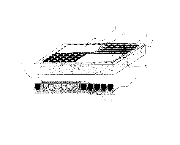
図3に示す更なる一例は、良熱伝導性材料として、ガム状熱伝導手段を用いた例である。本例で示すガム状の熱伝導手段は、チップの基板面と加熱手段、または、冷却手段の間に圧着することにより密着し、効率よく熱伝導を行う。図3に示す加熱手段、または、冷却手段は、マイクロチューブ等を対象としたヒートブロックタイプのものを例示した。この例では、マイクロチューブ等を穴に差し込んで壁面を通じて熱伝導を行う形態の加熱手段、または、冷却手段を利用する際、ガム状の熱伝導手段を穴内部にまで充填することで、熱伝達効率が向上する。
【0027】
利用するガム状の熱伝導手段は、適度な流動性を有していることが望ましい。但し、加熱、または、冷却に伴い、その流動性に著しい変化が現れるものは、熱伝達効率も変化する可能性が高く、多くの場合望ましくない。一般に、遺伝子検出操作において、遺伝子チップの温度は、数℃〜95℃程度の範囲に設定されるため、この温度範囲で、流動性、可塑性を維持するものを選択することが好ましい。ガム状の熱伝導手段の材質は、上記の流動性要件を満たすとともに、極力、熱伝導効率の高いものを選択することが望ましい。
【0028】
図1から図3には、遺伝子チップのスライドグラス状基板の背面全体に、良熱伝導性材料として、熱伝導ユニット等を狭着する形態を例示したが、プローブを固定化したアレイの形状に応じて、利用する良熱伝導性材料(熱伝導手段)の形状、位置を調整することも可能である。
【0029】
【実施例】
以下に実施例を挙げて、本発明をより具体的に説明する。なお、これら実施例は、本発明にかかる最良の実施形態の一例ではあるものの、本発明は、これら実施例の形態に限定されない。
【0030】
(実施例1)
DNAプローブ・アレイの作製
[1]ガラス基板の洗浄
合成石英のガラス基板(サイズ:25mm×75mm×1mm、飯山特殊ガラス社製)を耐熱、耐アルカリ性のラックに入れ、所定の濃度に調製した超音波洗浄用の洗浄液に浸した。一晩、洗浄液中に浸した後、20分間超音波洗浄を行った。続いて、基板を取り出し、軽く純水で漱いだ後、超純水中で20分超音波洗浄をおこなった。次に、80℃に加熱した1N水酸化ナトリウム水溶液中に10分間基板を浸した。再び純水洗浄と超純水洗浄を行い、DNAチップ用の洗浄済石英ガラス基板を用意した。
【0031】
[2]表面処理
シランカップリング剤;KBM−603(信越シリコーン社製)を、濃度1wt%となるように、純水中に溶解させ、2時間室温で攪拌した。続いて、洗浄済ガラス基板をシランカップリング剤水溶液に浸し、20分間室温で放置した。ガラス基板を引き上げ、軽く純水で基板表面を洗浄した後、基板の両面に窒素ガスを吹き付けて乾燥させた。次に、乾燥した基板を120℃に加熱したオーブン中で1時間ベークし、表面のカップリング剤処理を完結させた。このアミノシランカップリング剤処理に伴い、基板表面にアミノ基が導入される。
【0032】
一方、同仁化学研究所社製のN−マレイミドカプロイロキシスクシイミド(N−(6−Maleimidocaproyloxy)succinimido、以下、EMCSと略す)を、ジメチルスルホキシドとエタノールの1:1(体積比)混合溶媒中に最終濃度が0.3mg/mlとなるように溶解したEMCS溶液を用意した。ベークの終了後、ガラス基板を放冷し、次いで、調製したEMCS溶液中に室温で2時間浸した。この処理により、シランカップリング剤処理によって表面に導入されたアミノ基と、EMCSのスクシイミド基とが反応し、基板表面にEMCSに由来するマレイミド基が導入される。EMCS溶液から引き上げたガラス基板を、先述のジメチルスルホキシドとエタノールの混合溶媒を用いて洗浄する。さらに、エタノールにより洗浄した後、表面処理を施したガラス基板を窒素ガス雰囲気下で乾燥させた。
【0033】
[3]プローブDNAの合成
定法に従って、5’末端にスルファニル基による修飾を施した、下記塩基配列を有する18merのプローブDNAオリゴマー3種を合成した。
【0034】
合成後、DNAオリゴマーを高速液体クロマトグラフィーにより精製し、その後、脱塩、乾燥して、以下の実験に用いた。
【0036】
[4]BJプリンターによるDNAプローブ吐出、および基板への結合
予め、グリセリン7.5wt%、チオジグリコール7.5wt%、尿素7.5wt%、アセチレノールEH(川研ファインケミカル社製)1.0wt%を含む水溶液を用意した。続いて、合成した配列番号1の一本鎖DNAを、最終濃度が50マイクログラム/mlとなるように、上記の水溶液に溶解した。得られたDNA溶液を、バブルジェット・プリンター(商品名:BJF−850 キヤノン社製)用インクタンクに充填し、印字ヘッドに装着した。
【0037】
なお、ここで使用するバブルジェット・プリンターは、平板への印刷が可能なように改造を施したものである。また、このバブルジェット・プリンターは、所定のファイル作成方法に従って印字パターンを入力することにより、対応するパターンにインクドットの吐出を行い、約5ピコリットルのDNA溶液を約120マイクロメートルピッチでスポッティングすることが可能となっている。
【0038】
続いて、この改造バブルジェット・プリンターを用いて、1枚の表面処理済ガラス基板に対して、配列番号1〜3の各プローブをそれぞれ縦12個、横4個のマトリックス状に合計144個のスポットをスポッティングした。目的とするスポット印字が行われていることを確認した後、30分間加湿チャンバー内に静置して、ガラス基板表面のマレイミド基とDNAプローブ5’末端のスルファニル基とを反応させた。
【0039】
[5]洗浄
30分間の反応後、100mMのNaClを含む10mMのリン酸緩衝液(pH7.0)により表面に残ったDNA溶液を洗い流し、ガラス基板表面にマトリックス状にスポットされた一本鎖DNAが固定した遺伝子チップ(DNAプローブ・アレイ基板)を得た。
【0040】
アルミニウム製熱伝導ユニットの作製
図1に示す形状の熱伝導ユニットを、アルミニウムブロックから切削加工で作製した。作製した熱伝導ユニットのサイズは、遺伝子チップとの狭着面は、27mm×85mm×1.5mm、脚部は、φ10mm × 25mmの円筒形とした。脚部の取り付けピッチは、16mmとして、狭着面の裏面側に計4本をセットした。狭着面の四隅には、後述する送液用カバーを固定するため、ボルト受穴を設けた。
【0041】
送液用カバーの作製
遺伝子チップ表面のプローブ固定面に検体溶液、洗浄液を送液するために使用する送液用カバーを、アクリル樹脂を用いて作製した。プローブ固定面と送液用カバーの内面との間に所定の間隙を維持するため、0.5mm厚のスペーサーを設け、この間隙部を液室とした。送液用カバーと遺伝子チップのプローブ固定面の接点は、シリコンゴムのパッキンを用いて密閉する。送液用カバーの外面側に、内径1mmの液導入口、排出口をそれぞれ設けた。送液用カバーの固定は、送液用カバーの四隅に固定用ボルトを通すの穴を設け、上記の熱伝導ユニットの狭着面四隅に設けてあるねじ穴と対応させ、固定用ボルトによるボルト留めとする。
【0042】
また、外面側の液導入口には、シリコンゴムチューブを接続し、これをチューブポンプにセットした。排出口にも、シリコンゴムチューブを接続し、廃液ボトルへと接続した。
【0043】
遺伝子チップの装着
遺伝子チップと、熱伝導ユニット、送液用カバーを、下記する手順でセットアップした。
【0044】
まず、熱伝導ユニットの遺伝子チップとの狭着面に、耐熱性シリコングリスを薄く塗布した後、遺伝子チップの背面を圧着した。圧着の際、グリスと遺伝子チップ背面との密着性を高めるため、気泡の侵入を生じないように注意した。続いて、送液用カバーを遺伝子チップ表面側、プローブ固定面を覆うように被せ、4本の固定用ボルトによる付加荷重が均一となるように留意しながら締め込み、送液用カバーを固定した。
【0045】
遺伝子チップ、熱伝導ユニット、送液用カバーを組み立てたものを、ヒートブロック装置(岩城硝子社製、CHT−100)上にセットした。用いた該装置のヒートブロックは、1.5〜2.0mlマイクロチューブ用アルミブロックである。
【0046】
検証用モデル検体の準備
上記の温度制御機構の機能検証に利用するモデル検体を、下記するように調製した。モデル標的核酸(遺伝子)として、配列番号1の一本鎖核酸断片と相補的な塩基配列を有する一本鎖核酸断片を合成し、定法に従って5’末端に蛍光色素(ローダミン)を標識した。合成したモデル標的核酸を用いて、以下に示す組成物(モデル検体)を調製した。
【0047】
[モデル検体組成]
【0048】
【表1】
ブロッキング/ハイブリダイゼーション
組み立て後、ヒートブロック装置にセットされた遺伝子チップに対して、チューブポンプを用いて、まず、ブロッキング溶液を液室に充填した。ブロッキング液は、生理食塩水(PBS)に2%(w/w)になるように牛血清アルブミン(BSA)を溶解したものを用いた。遺伝子チップのプローブ固定面と送液用カバーの隙間(液室)にブロッキング液を充填した後、チューブポンプを停止し、排出口側もピンチコックで密閉した。密閉状態とした後、室温で2時間静置した。
【0050】
2時間静置後、ヒートブロックを55℃に予熱した後、排出口のピンチコックを外し、チューブポンプを用いて液導入口から上記モデル検体を送液し、液室内をモデル検体で置換し、充填した。なお、モデル検体液には、遺伝子チップへの充填直前に、95℃、3分の熱変性処理と急冷処理を施してある。遺伝子チップのプローブ固定面と送液用カバーの隙間(液室)内にモデル検体液が充填された後、チューブポンプを停止し、排出口側もピンチコックで密閉した。
この密閉状態を保ったまま、ヒートブロックを55℃に温度調節しつつ、16時間静置した。
【0051】
洗浄
16時間の保温静置後、排出口のピンチコックを外し、以下に示す洗浄液1を液導入口からチューブポンプを用いて送液し、遺伝子チップを洗浄した。洗浄液1の送液量は、1ml/分とし、その間、ヒートブロックの温度は55℃に保持したまま、10分間洗浄を行った。
【0052】
[洗浄液1の組成]
【0053】
【表2】
次に、洗浄液1の送液を停止し、ヒートブロックの温度を25℃に変更した。洗浄液1を以下に示す洗浄液2に付け替え、ヒートブロックの温度が25℃で安定したのを確認した後、1ml/分の送液量で洗浄液2を送液し、洗浄を再開し、3分間洗浄を行った。
【0055】
[洗浄液2の組成]
【0056】
【表3】
乾燥
洗浄操作の終了後、セットアップ済みの遺伝子チップをヒートブロック装置から取り外す。さらに、熱伝導ユニット、送液用カバーを外して、スライド・ガラス状態の遺伝子チップを取り出した。取り出した遺伝子チップは、窒素ガスでブローして乾燥させた。
【0058】
蛍光測定
乾燥した遺伝子チップを、アレイスキャナーGenePix 400B(Axon社製)にセットし、定法に従って、マトリックス状DNAアレイ中の各スポット毎に蛍光測定を行った。具体的には、波長532nmのレーザーを用いて、遺伝子チップのプローブ固定面をスキャンして、モデル標的核酸を標識するローダミンの蛍光を測定した。
【0059】
測定の結果
蛍光測定は、アレイスキャナー付属の解析ソフトウェア(GenePix Pro 3.0)を用いて行った。蛍光量測定は、スキャン解像度5ミクロン、スポットの検出はオートアライメントで行い、検出されたスポットの中心部32ピクセルの輝度(蛍光強度)の総和で比較した。
【0060】
配列番号1のDNAプローブ・スポットの平均蛍光輝度を100とした場合、配列番号2のDNAプローブ・スポットでは、40、配列番号3のDNAプローブ・スポットでは、8の蛍光輝度を示した。また、配列番号1のDNAプローブ・スポット、計48個内でのバラツキは、最大値は、平均値の109%、最小値は、平均値の93%であった。配列番号2のDNAプローブ・スポット、計48個内でのバラツキは、最大値は、平均値の111%、最小値は、平均値の90%であった。配列番号3のDNAプローブ・スポット、計48個内でのバラツキは、最大値は、平均値の108%、最小値は、平均値の89%であった。
【0061】
(比較例1)
実施例1と同様に、石英ガラス基板を用いた遺伝子チップを作製した。この遺伝子チップを使用して、市販のハイブリ・カセットとオーブンを用いて検出操作を行った。実施例1との相違点は、以下の通り。
【0062】
熱伝導ユニット、送液用カバーを用いず、定法に従って、プローブ固定面を市販のカバーグラスで被覆し、ハイブリ・カセットを用いるハイブリダイゼーションを行った。ハイブリダイゼーション反応中の温度制御は、オーブンで行った。その後の洗浄では、ウォーターバスを用いて洗浄液の温度制御を行った。
【0063】
測定の結果
標識による蛍光の測定方法・手順は、実施例1と同様である。
【0064】
配列番号1のDNAプローブ・スポットの平均蛍光輝度を100とした場合、配列番号2のDNAプローブ・スポットでは、65、配列番号3のDNAプローブ・スポットでは、34の蛍光輝度を示した。また、配列番号1のDNAプローブ・スポット、計48個内でのバラツキは、最大値は、平均値の121%、最小値は、平均値の82%であった。配列番号2のDNAプローブ・スポット、計48個内でのバラツキは、最大値は、平均値の144%、最小値は、平均値の56%であった。配列番号3のDNAプローブ・スポット、計48個内でのバラツキは、最大値は、平均値の137%、最小値は、平均値の52%であった。
【0065】
(実施例2)
遺伝子チップの作製
実施例1と同様に作製した。
【0066】
アルミニウム製熱伝導ユニットの作製
図2に示す形状の熱伝導ユニットを、アルミニウムブロックより切削で作製した。作製した熱伝導ユニットのサイズは、遺伝子チップとの狭着面は、27mm×85mm×1.5mm、脚部は、基部はφ6mm、末端部はφ3mm、総高さ11mmの円錐台形とした。脚部の取り付けピッチは、9mmとして、狭着面の裏面側に3列8本で計24本をセットした。狭着面の四隅には、後述する送液用カバーを固定するため、ボルト受穴を設けた。
【0067】
送液用カバーの作製
実施例1と同様のものを作製し、用いた。
【0068】
遺伝子チップの装着
遺伝子チップと、熱伝導ユニット、送液用カバーを、実施例1と同様の手順でセットアップした。
【0069】
遺伝子チップ、熱伝導ユニット、送液用カバーを組み立てたものを、PCR装置(MJResearch社製、PCT−100)の加熱ブロック上にセットした。
【0070】
モデル検体の準備
実施例1と同様に、モデル検体の調製を行った。
【0071】
ブロッキング/ハイブリダイゼーションと洗浄、乾燥
実施例1と同様の条件で行った。
【0072】
蛍光測定、解析の結果
標識による蛍光の測定方法・手順は、実施例1と同様である。
【0073】
配列番号1のDNAプローブ・スポットの平均蛍光輝度を100とした場合、配列番号2のDNAプローブ・スポットでは、42、配列番号3のDNAプローブ・スポットでは、11の蛍光輝度を示した。また、配列番号1のDNAプローブ・スポット、計48個内でのバラツキは、最大値は、平均値の107%、最小値は、平均値の94%であった。配列番号2のDNAプローブ・スポット、計48個内でのバラツキは、最大値は、平均値の110%、最小値は、平均値の93%であった。配列番号3のDNAプローブ・スポット、計48個内でのバラツキは、最大値は、平均値の112%、最小値は、平均値の91%であった。
【0074】
(実施例3)
遺伝子チップの作製
実施例1と同様に作製した。
【0075】
送液用カバーの作製
実施例1と同様のものを作製し、用いた。
【0076】
アルミニウム製受用ユニット板の作製と良熱伝導性材料の調製
アルミニウム製受用ユニット板として、厚さ1.5mmのアルミニウム板を、幅27mm長さ85mmのサイズに切り出し、実施例1で作製した送液用カバー固定用に四隅にボルトの受穴を設けた。別に、良熱伝導性材料用に、シリコン樹脂コーキング剤に粉末状の銅を80%(w/w)になるように加え、均一になるようすばやく混練し、熱伝導性コーキング剤を調製した。
【0077】
遺伝子チップの装着
遺伝子チップと、送液用カバー、送液用カバーの受用アルミ板を、下記する手順でセットアップした。
【0078】
まず、受用アルミ板の上面に、耐熱性シリコングリスを薄く塗布した後、遺伝子チップの背面を圧着した。圧着の際、グリスと遺伝子チップ背面との密着性を高めるため、気泡の侵入を生じないように注意した。続いて、送液用カバーを遺伝子チップ表面側、プローブ固定面を覆うように被せ、4本の固定用ボルトによる付加荷重が均一となるように留意しながら締め込み、送液用カバーを固定した。
【0079】
銅紛を混入したシリコン樹脂コーキング剤をPCR装置(MJ Research社製、PCT−100)のヒートブロック上に適量乗せ、ダミーの送液用カバーの受用アルミ板を用いて必要な大きさに伸ばしてセットした。この伸張された銅紛入りコーキング剤の上に、受用アルミ板を前記コーキング剤と密着するように、遺伝子チップ、送液用カバー、受用アルミ板を組み立てたものを圧着させ、装着を完了した。
【0080】
モデル検体の準備
実施例1と同様に、モデル検体の調製を行った。
【0081】
ブロッキング/ハイブリダイゼーションと洗浄、乾燥
実施例1と同様の条件で行った。
【0082】
蛍光測定、解析の結果
標識による蛍光の測定方法・手順は、実施例1と同様である。
【0083】
配列番号1のDNAプローブ・スポットの平均蛍光輝度を100とした場合、配列番号2のDNAプローブ・スポットでは、39、配列番号3のDNAプローブ・スポットでは、9の蛍光輝度を示した。また、配列番号1のDNAプローブ・スポット、計48個内でのバラツキは、最大値は、平均値の105%、最小値は、平均値の91%であった。配列番号2のDNAプローブ・スポット、計48個内でのバラツキは、最大値は、平均値の109%、最小値は、平均値の95%であった。配列番号3のDNAプローブ・スポット、計48個内でのバラツキは、最大値は、平均値の111%、最小値は、平均値の90%であった。
【0084】
(実施例4)
遺伝子チップの作製
実施例1と同様に作製した。
【0085】
送液用カバーの作製
基本的に実施例1と同様のものを作製したが、液導入口と排出口には、フレキシブルチューブ(シリコンチューブ、内径1mm)を接続し用いた。
【0086】
アルミニウム製受用ユニット板の作製と良熱伝導性材料の調製
アルミニウム製受用ユニット板として、厚さ1.5mmのアルミニウム板を、幅27mm長さ85mmのサイズに切り出し、実施例1で作製した送液用カバー固定用に四隅にボルトの受穴を設けた。別に、良熱伝導性材料用に、シリコン樹脂コーキング剤に粉末状の銅を80%(w/w)になるように加え、均一になるようすばやく混練し、熱伝導性コーキング剤を調製した。
【0087】
遺伝子チップの装着
実施例3と同様に遺伝子チップ、送液カバー受用ユニットをセットした。
【0088】
銅紛を混入したシリコン樹脂コーキング剤をPCR装置(MJ Research社製、PCT−100)のヒートブロック上に適量乗せ、ダミーの送液用カバーの受用アルミ板を用いて必要な大きさに伸ばしてセットした。この伸張された銅紛入りコーキング剤の上に、送液カバーの上面がコーキング剤と密着するように、遺伝子チップ、送液用カバー、受用アルミ板を組み立てたものを厚着し、装着を完了した。この際、液導入口と排出口に接続されたフレキシブルチューブがコーキング剤と送液カバーの密着を妨げないよう、また、折れ曲がり等によって送液が妨げられないように注意した。
【0089】
モデル検体の準備
実施例1と同様に、モデル検体の調製を行った。
【0090】
ブロッキング/ハイブリダイゼーションと洗浄、乾燥
実施例1と同様の条件で行った。
【0091】
蛍光測定、解析の結果
標識による蛍光の測定方法・手順は、実施例1と同様である。
【0092】
配列番号1のDNAプローブ・スポットの平均蛍光輝度を100とした場合、配列番号2のDNAプローブ・スポットでは、37、配列番号3のDNAプローブ・スポットでは、10の蛍光輝度を示した。また、配列番号1のDNAプローブ・スポット、計48個内でのバラツキは、最大値は、平均値の108%、最小値は、平均値の92%であった。配列番号2のDNAプローブ・スポット、計48個内でのバラツキは、最大値は、平均値の111%、最小値は、平均値の94%であった。配列番号3のDNAプローブ・スポット、計48個内でのバラツキは、最大値は、平均値の110%、最小値は、平均値の92%であった。
【0093】
【発明の効果】
本発明においては、遺伝子チップを用いた遺伝子検出操作の際、遺伝子チップの温度を制御する手段として、汎用性を有する形状の、熱伝導性に優れた材質を用いた構成される良熱伝導性材料を、基板の背面、もしくは、検出用一本鎖核酸断片を固定化した面の対面に、実質的に基板面全体を覆う、あるいは、狭着される形態で配置することで、基板面全体の面内方向の熱拡散を向上させ、加えて、かかる良熱伝導性材料を介して、熱の授受を行う温度制御手段を利用することで、遺伝子チップ全体を所望の温度に精度良く、再現性良く温度制御することを可能としている。また、かかる温度制御手段は、安価な部材、装置を用いることで構成でき、また、遺伝子チップに利用される基板形状に応じて、簡便に変更可能である。そのため、高い汎用性を有するとともに、この温度制御手段を利用することで、遺伝子検出操作における遺伝子チップ内の温度バラツキも抑制され、測定自体の精度、再現性の向上が図れる。
【図面の簡単な説明】
【図1】本発明にかかる温度制御装置に利用される、熱伝導ユニットの一実施態様を模式的に示す図である。
【図2】本発明にかかる温度制御装置に利用される、熱伝導ユニットの別の一実施態様を模式的に示す図である。
【図3】本発明にかかる温度制御装置に利用される、良熱伝導性材料の一実施態様を模式的に示す図である。
【図4】本発明にかかる温度制御装置における、遺伝子チップ装着部構成の一実施態様を模式的に示す図である。
【図5】本発明にかかる温度制御装置における、遺伝子チップの装着状態の一実施態様を模式的に示す図である。
【符号の説明】
1 遺伝子チップ狭着面
2 脚部
3 ヒートブロック
4 遺伝子チップ
5 熱伝導性部材(ガム状)
6 液導入口
7 排出口
8 送液用カバー
9 遺伝子チップ
10 熱伝導性ユニット(板状)[0001]
TECHNICAL FIELD OF THE INVENTION
The present invention relates to an apparatus used for detecting and measuring a gene using a nucleic acid probe substrate, and more specifically, when detecting and measuring a gene DNA by a hybridization method, a plurality of single-stranded nucleic acids are used as a nucleic acid probe. An apparatus having a function of achieving contact between a specimen sample and each nucleic acid probe on a substrate on which seeds are immobilized in an array at a desired temperature condition, and detection and measurement of a gene nucleic acid using the apparatus. On how to do.
[0002]
[Prior art]
As a development of the method of detecting and measuring gene DNA based on the hybridization method, applications where multiple types of nucleic acid probes are immobilized on a substrate and multiple detection tests are performed simultaneously on the gene DNA contained in the sample sample In recent years, research on gene chips (DNA chips, microarrays) has rapidly progressed. The method for detecting and measuring gene DNA contained in a specimen sample using such a gene chip (DNA chip, microarray) is expected to be applied in various fields such as molecular biology research, genetic disease and infectious disease diagnosis. I have.
[0003]
The basic form of a gene chip is based on a hybridization method, and in order to detect a target gene DNA, a plurality of single-stranded nucleic acid fragments having a base sequence complementary to the base sequence of the target gene are prepared by using glass, etc. Are immobilized in an array on the surface of the substrate. A single-stranded nucleic acid fragment having a complementary base sequence, which is used as a hybridization probe for the target gene, is called oligo DNA, a chemically synthesized DNA oligomer or cDNA, or a biological tissue-derived cDNA. Generally, a complementary-strand DNA fragment enzymatically biosynthesized using a gene as a template is used. For immobilization of a single-stranded nucleic acid fragment on a substrate surface, for oligo DNA, for example, a method described in US Pat. No. 5,474,796 (or Japanese Patent Application Laid-Open No. 9-500568, applicant: ProtoGene Laboratories). As described above, a method of sequentially synthesizing DNA molecules themselves on a substrate after fixing the terminal in advance to obtain an immobilized nucleic acid fragment is disclosed in, for example, JP-A-11-187900 (Applicant: Canon Inc.) As described in the above method, the method is roughly divided into a method in which oligo DNA is separately synthesized, and a nucleic acid fragment is immobilized on a substrate by using various binding means.
[0004]
As a means for immobilizing a separately prepared nucleic acid fragment on a substrate, various methods, for example, an adsorption fixing method using the charge of the substrate and the charge of the nucleic acid fragment, or a poly-L-lysine, aminosilane coupling agent For example, there has been proposed a fixing method in which the substrate surface is coated with a coating material, and the coating film is used to improve fixing efficiency.
[0005]
[Problems to be solved by the invention]
On the other hand, in a hybridization reaction (hybridization reaction) with respect to a nucleic acid probe immobilized on a substrate, the gene DNA contained in the sample solution is converted into a single strand, and complementary to the base sequence of the nucleic acid probe. To form a double-stranded structure. Therefore, it is necessary to heat the nucleic acid probe and the sample solution to a predetermined temperature. In addition, in some cases, a gene DNA having a similar base sequence, although not a base sequence complementary to the base sequence of the nucleic acid probe, may also cause a pseudocross reaction (mismatch hybridization reaction), and Forms a loose bond. Furthermore, unreacted contaminant DNA having no similarity in base sequence may adhere to the substrate surface due to physical adsorption or the like. Since these weakly bound and unnecessary DNA molecules are selectively removed, the gene DNA achieving the target hybridization reaction is not redissolved, but the weakly bound and unnecessary DNA molecules are removed. The cleaning and removal step is performed by heating to a temperature at which separation proceeds.
[0006]
In the detection operation using a gene chip, in order to detect only the target gene DNA with high reproducibility, particularly in the hybridization reaction step between the target gene in the sample and the nucleic acid (probe) immobilized on the gene chip. It is necessary to control the heating temperature and the heating temperature in the washing step for selectively removing similar genes and unreacted contaminants that have caused the pseudocross reaction with high accuracy. In general, temperature fluctuation between each process has a great effect on reproducibility of a detection result.
[0007]
Several means have been proposed for suppressing a decrease in detection accuracy and reproducibility due to the temperature fluctuation between the respective steps. For example, a polynucleotide detection chip and a polynucleotide detection device described in Japanese Patent Application Laid-Open No. 2000-342264 are capable of detecting a nucleic acid fragment (probe) having a sequence complementary to a target gene contained in a sample for each type. By adopting a method in which sections are set and minute heaters are provided for each section of the detection chip, appropriate temperature control is performed. In this method, the configuration of the device becomes very complicated, and the dedicated detection chip and the entire detection device must be expensive. In addition, the miniaturization of the entire apparatus is difficult due to the provision of the minute heater for each section.
[0008]
In the method and apparatus for detecting a hybridization reaction described in Japanese Patent Application Laid-Open No. 2001-255328, the influence of a temperature change of an array formed on a glass substrate is eliminated by tracking changes over time during the reaction. Then, we aim for high-precision detection. However, according to this method, it is necessary to continuously track and inspect one array using a device such as a microscope during the reaction, and it is difficult to inspect a large number of array substrates.
[0009]
Further, gene chips packaged in a unique shape represented by GeneChip (manufactured by Affymetrix) are also commercially available. These commercially available gene chips are gene chips premised on a detection operation using a corresponding dedicated device, and therefore have poor versatility. Further, not only the dedicated device but also the gene chip itself is very expensive.
[0010]
On the other hand, in research applications at universities and the like, it is necessary to prepare a unique chip on which various nucleic acid fragments for detection are immobilized so as to be adapted to individual applications. Therefore, a method of fixing nucleic acid fragments on a slide glass substrate surface-treated with poly-L-lysine or the like using an array manufacturing apparatus called a pin spotter is generally used. The gene chip produced on a general-purpose slide glass substrate produced by this method is a seemingly simple glass plate, and of course, is not devised for temperature control.
[0011]
For example, it can be applied to the case where a gene chip manufactured on a general-purpose slide glass substrate used in the above research application is used, and a temperature at which the temperature of the entire gene chip can be controlled with high reproducibility and uniformity. It is desired to develop a detection device having control means and having low cost and high versatility as a whole.
[0012]
The present invention solves the above-mentioned problems, and an object of the present invention is applicable to a highly versatile gene chip used for various applications, and in addition, the temperature of the entire gene chip can be highly reproducible. Equipped with a temperature control means that can be controlled with uniformity, and furthermore, satisfying low cost, detecting and measuring a gene using a nucleic acid probe substrate, and using the device. Another object of the present invention is to provide a method for detecting and measuring a gene nucleic acid.
[0013]
[Means for Solving the Problems]
The present inventor has conducted intensive research to solve the above-mentioned problems, and found that the slide glass substrate itself used for producing the gene chip was used to control the temperature of the entire gene chip with high reproducibility and uniformity. Have found that the thermal conductivity is not always high, which is a factor that causes local unevenness in temperature distribution. Based on this finding, as a result of further study, a good heat conductive material was narrowly attached to the back of the slide glass substrate, and the heat diffusion in the in-plane direction was effectively performed through the good heat conductive material. At the same time, when the good heat conductive material is brought into direct contact with the heating means or the cooling means to control the temperature of the good heat conductive material itself, the whole of the tightly mounted slide glass substrate does not have temperature non-uniformity. The inventor has found that the desired temperature can be maintained with high accuracy, and the present inventors have completed the present invention.
[0014]
That is, the first embodiment of the temperature control apparatus for a nucleic acid probe array substrate according to the present invention is based on a hybridization method, in which a target gene DNA contained in a sample is detected. For a substrate in which a plurality of nucleic acid probes containing a single-stranded nucleic acid fragment having a complementary base sequence to a sequence are immobilized in an array on the surface of the substrate, the temperature of the specimen and the temperature of the substrate during the gene detection operation A nucleic acid probe / array substrate temperature controller for controlling,
On the back surface of the substrate in which the single-stranded nucleic acid fragments are immobilized in an array on the surface of the substrate, a good heat conductive material tightly attached to the substrate back surface,
Heating means or cooling means in contact with the good heat conductive material,
Means for controlling the amount of heat moving between the heating means or the cooling means and the good heat conductive material, and means for controlling the temperature of the good heat conductive material,
A temperature controller for a nucleic acid probe / array substrate, having a function of controlling the temperature of the substrate to be tightly attached thereto through the temperature control of the good heat conductive material. Further, the second embodiment of the temperature control apparatus for a nucleic acid probe array substrate according to the present invention is a method for detecting a target gene DNA contained in a sample based on a hybridization method. For a substrate in which a plurality of nucleic acid probes containing a single-stranded nucleic acid fragment having a complementary base sequence to a sequence are immobilized in an array on the surface of the substrate, the temperature of the specimen and the temperature of the substrate during the gene detection operation A nucleic acid probe / array substrate temperature controller for controlling,
Good heat conduction is provided in contact with the surface of the substrate in which a plurality of types of the single-stranded nucleic acid fragments are immobilized in an array on the surface of the substrate in a space for supplying the specimen, facing the surface of the substrate, and installed. Material and
Heating means or cooling means in contact with the good heat conductive material,
Means for controlling the amount of heat moving between the heating means or the cooling means and the good heat conductive material, and means for controlling the temperature of the good heat conductive material,
A nucleic acid probe having a function of controlling the temperature of the sample supplied to the gap and the temperature of the substrate surface through contact with the good heat conductive material through the temperature control of the good heat conductive material. -An array substrate temperature controller. In this case, it is preferable that the good heat conductive material is formed of one of a metal and a resin, or a composite of two or more of these.
[0015]
Furthermore, the present invention also provides a method for detecting a gene by using the temperature control means of the nucleic acid probe array substrate, that is, a first embodiment of the gene detection method according to the present invention comprises:
In order to detect a target gene DNA contained in a sample based on a hybridization method, a plurality of nucleic acid probes containing a single-stranded nucleic acid fragment having a base sequence complementary to the base sequence of the target gene DNA A method for detecting a gene using a substrate in which seeds are immobilized in an array on the substrate surface as detection means,
For the back surface of the substrate in which the single-stranded nucleic acid fragments are immobilized in an array on the surface of the substrate, a good heat conductive material that is tightly attached to the back surface of the substrate is arranged.
Arranging a heating means or a cooling means in contact with the good heat conductive material,
Controlling the amount of heat moving between the heating means or the cooling means and the good heat conductive material, providing means for controlling the temperature of the good heat conductive material,
During the gene detection operation, the detection operation is performed while controlling the temperature of the substrate to be tightly attached and the sample in contact with the substrate surface through the temperature control of the good heat conductive material based on the means. This is a method for detecting genes. At that time, in the plurality of steps included in the gene detection operation, the substrate, the temperature of the sample in contact with the substrate surface is controlled,
A temperature control unit utilizing the heating unit may sequentially control the temperatures of the plurality of steps requiring temperature control. Alternatively, included in the gene detection operation, in a plurality of steps, the substrate, the temperature of the sample in contact with the substrate surface is performed,
The method may be characterized in that temperatures of the plurality of steps requiring temperature control are sequentially controlled by temperature control means utilizing the cooling means. The substrate and the good thermal conductive material used for controlling the temperature of the specimen in contact with the surface of the substrate may be any one of a metal and a resin, or may be formed by combining two or more of these. Preferably, a thermally conductive material is used.
[0016]
In addition, the second embodiment of the gene detection method according to the present invention,
In order to detect a target gene DNA contained in a sample based on a hybridization method, a plurality of nucleic acid probes containing a single-stranded nucleic acid fragment having a base sequence complementary to the base sequence of the target gene DNA A method for detecting a gene using a substrate in which seeds are immobilized in an array on the substrate surface as detection means,
Good heat conduction is provided in contact with the surface of the substrate in which a plurality of types of the single-stranded nucleic acid fragments are immobilized in an array on the surface of the substrate in a space for supplying the specimen, facing the surface of the substrate, and installed. Place the conductive material,
Arranging a heating means or a cooling means in contact with the good heat conductive material,
Controlling the amount of heat moving between the heating means or the cooling means and the good heat conductive material, providing means for controlling the temperature of the good heat conductive material,
During the gene detection operation, through the temperature control of the good heat conductive material based on the means, having contact with the good heat conductive material, while controlling the temperature of the specimen supplied to the gap and the substrate surface, A gene detection method comprising performing a detection operation. At that time, in the plurality of steps included in the gene detection operation, the substrate, the temperature of the sample in contact with the substrate surface is controlled,
A temperature control unit utilizing the heating unit may sequentially control the temperatures of the plurality of steps requiring temperature control. Alternatively, included in the gene detection operation, in a plurality of steps, the substrate, the temperature of the sample in contact with the substrate surface is performed,
The method may be characterized in that temperatures of the plurality of steps requiring temperature control are sequentially controlled by temperature control means utilizing the cooling means. The substrate and the good thermal conductive material used for controlling the temperature of the specimen in contact with the surface of the substrate may be any one of a metal and a resin, or may be formed by combining two or more of these. Preferably, a thermally conductive material is used.
[0017]
BEST MODE FOR CARRYING OUT THE INVENTION
Hereinafter, the present invention will be described in more detail.
[0018]
Specifically, the feature of the present invention is that the entire substrate on which a single-stranded nucleic acid fragment having a nucleotide sequence complementary to the target gene is immobilized to detect the target gene contained in the sample is heated to a desired temperature. When controlling, on the back of the substrate, or on the surface opposite to the surface on which the single-stranded nucleic acid fragment for detection is immobilized, a good heat conductive material composed of a material having excellent heat conductivity is substantially applied to the substrate. By covering the entire surface or arranging it in a form to be tightly attached, heat diffusion in the in-plane direction of the entire substrate surface is improved, and heat is transferred through such a good heat conductive material. The temperature control means is provided.
[0019]
The good heat conductive material used for the heat conducting means is not obstructed in the step of preparing the nucleic acid probe / array substrate, particularly, the step of immobilizing the single-stranded nucleic acid fragment for detection on the substrate surface. Prior to the step of immobilizing the single-stranded nucleic acid fragment for detection, it may be narrowly attached to the back surface of the substrate or the like. In addition, there is no problem even if a means such as permanent bonding is used for the narrow attachment of the good heat conductive material, or a configuration that can be removed is used. However, it is necessary that the slide glass substrate used for the nucleic acid probe array substrate and the entire surface of the substrate be in such a form that close thermal contact and adhesion can be sufficiently achieved. An example of the narrowing method is as follows. For example, a small amount of an adhesive paste is applied to a gap between a substrate (hereinafter, a chip) on which a single-stranded nucleic acid fragment for detection (hereinafter, a probe) is immobilized and a good heat conductive material. There is a method in which the paste thin film layer is tightly adhered by utilizing the adhesiveness of the paste thin film layer.
[0020]
At this time, a material that does not harden or dry due to heating / cooling (temperature control) during the detection operation is selected as the adhesive paste. The thickness of the paste thin film layer is preferably selected to be as thin as possible within a range in which the adhesiveness can be exhibited. That is, the amount of the paste should be as small as possible, and care should be taken so as not to hinder the heat conduction between the good heat conductive material and the back surface of the substrate. If the paste used has sufficient thermal conductivity, which is comparable to that of a good thermal conductive material, the thickness of the paste thin film layer is preferably as small as possible. It can be set to a thick range.
[0021]
Examples of the material for the heat conducting means, which is the above-mentioned good heat conducting material, include metals and resins. More specifically, usable metals include iron, aluminum, copper, brass, stainless steel, and the like. A block-shaped or plate-shaped lump can be used as the good heat conductive material using these metals. Furthermore, it is also possible to use a material formed into a material exhibiting uniform thermal conductivity, for example, by sintering a subdivided material such as a flake. The resin material used as the heat conducting means is not particularly specified, but it is more preferable that the resin material exhibit higher heat conducting properties.For example, the heat conducting performance is enhanced by mixing powdered metal or the like. Is desirable.
[0022]
As a good heat conductive material, the shape of the heat conducting means is, in the case of a solid state, of course, a flat surface portion tightly attached to the back surface of the substrate or the like, but is brought into contact with the heat conducting means, heating means, or It is desirable to shape the cooling means so as to allow good contact according to the shape of the cooling means. That is, the amount of heat transferred to the substrate via this heat conducting means should be such that the heat is transmitted uniformly to the probe fixing region of the chip on which the nucleic acid probe is fixed, which is arranged on the substrate surface. desirable. Further, the heat conducting means does not necessarily need to be used in a solid state. For example, the heat conducting means may be used in a paste state or a gum state having fluidity.
[0023]
Hereinafter, typical embodiments of the present invention will be described in detail with reference to the drawings.
[0024]
FIG. 1 shows an example of a metal heat conducting unit used in the present invention. FIG. 2 shows another example. In the heat conducting means shown in FIGS. 1 and 2, the rear surface of the substrate of the gene chip is narrowed to the gene chip narrowing surface 1 having a flat surface. On the other hand, the leg 2 provided on the back side of the narrow attachment surface 1 is shaped according to the shape of the heating means or the cooling means. Utilizing such a leg 2, it is set on a temperature control means (not shown). In this example, when a commercially available heat block device or a programmable heat block device for PCR (Polymerase Chain Reaction) is used as a temperature control means, the shape of the heat conduction unit is assumed to be set in those heat blocks. Indicated. That is, the leg portions 2 in FIGS. 1 and 2 are arranged and formed so as to be insertable into the holes for inserting microtubes in the heat block.
[0025]
In order to increase the thermal conductivity between the heating means and the cooling means, it is desirable that the size of the leg portion 2 is such that it can be in close contact with the insertion hole of the heat block. The shape of the heat block must be designed in consideration of the coefficient of thermal expansion of the heat block, the coefficient of thermal expansion of the metal material constituting the exemplified heat conducting unit, and the like. Taking this point into consideration, oil or the like may be used to fill the gap between the leg 2 and the insertion hole of the heat block and complement thermal conductivity. As the material of the heat conduction unit, aluminum or the like is preferably used because it is relatively lightweight and has excellent workability. The heat conduction unit having the shape shown in FIGS. 1 and 2 can be made of resin. However, in general, resin has poor thermal conductivity as compared with a metal material, and as a result, there is a disadvantage that the temperature responsiveness of the chip is slower than when a metal material is used. An ABS resin or the like having a relatively high density shows good characteristics as compared with a Teflon resin or the like, but has a significantly lower thermal conductivity as compared with a metal such as aluminum. In addition, when using resin as the heat transfer unit, consider the heating temperature required for the detection operation, and use a resin that shows sufficient thermal resistance at that heating temperature even when it is used repeatedly. Is desirable.
[0026]
A further example shown in FIG. 3 is an example in which gum-like heat conducting means is used as a good heat conducting material. The gum-like heat conducting means shown in this example is brought into close contact with the chip surface by being pressed against the substrate surface of the chip and the heating means or the cooling means, and conducts heat efficiently. The heating means or the cooling means shown in FIG. 3 is exemplified by a heat block type for a microtube or the like. In this example, when a heating means or a cooling means in which a microtube or the like is inserted into the hole to conduct heat through the wall surface or a cooling means is used, heat transfer is performed by filling the inside of the hole with a gum-like heat conduction means. Efficiency is improved.
[0027]
It is desirable that the gum-like heat conduction means used has appropriate fluidity. However, a material whose flowability significantly changes with heating or cooling is likely to change the heat transfer efficiency, which is undesirable in many cases. Generally, in a gene detection operation, the temperature of a gene chip is set in a range of about several degrees Celsius to 95 degrees Celsius. Therefore, it is preferable to select one that maintains fluidity and plasticity in this temperature range. As the material of the gum-like heat conducting means, it is desirable to select a material that satisfies the above-mentioned fluidity requirements and has as high a heat conducting efficiency as possible.
[0028]
FIGS. 1 to 3 show an example in which a heat conductive unit or the like is tightly attached as a good heat conductive material on the entire back surface of a slide glass substrate of a gene chip. Accordingly, it is also possible to adjust the shape and position of the good heat conductive material (heat conducting means) to be used.
[0029]
【Example】
Hereinafter, the present invention will be described more specifically with reference to examples. Although these examples are only examples of the best embodiments according to the present invention, the present invention is not limited to these embodiments.
[0030]
(Example 1)
Preparation of DNA probe array
[1] Cleaning of glass substrate
A synthetic quartz glass substrate (size: 25 mm × 75 mm × 1 mm, manufactured by Iiyama Special Glass Co., Ltd.) was placed in a heat-resistant and alkali-resistant rack and immersed in a cleaning solution for ultrasonic cleaning prepared at a predetermined concentration. After immersing in the cleaning solution overnight, ultrasonic cleaning was performed for 20 minutes. Subsequently, the substrate was taken out, lightly rinsed with pure water, and then subjected to ultrasonic cleaning in ultrapure water for 20 minutes. Next, the substrate was immersed in a 1N aqueous solution of sodium hydroxide heated to 80 ° C. for 10 minutes. Pure water washing and ultrapure water washing were performed again to prepare a washed quartz glass substrate for a DNA chip.
[0031]
[2] Surface treatment
A silane coupling agent; KBM-603 (manufactured by Shin-Etsu Silicone Co., Ltd.) was dissolved in pure water so as to have a concentration of 1 wt%, and stirred at room temperature for 2 hours. Subsequently, the washed glass substrate was immersed in an aqueous solution of a silane coupling agent, and left at room temperature for 20 minutes. The glass substrate was pulled up, the substrate surface was lightly washed with pure water, and then dried by blowing nitrogen gas to both surfaces of the substrate. Next, the dried substrate was baked in an oven heated to 120 ° C. for 1 hour to complete the coupling agent treatment on the surface. With this aminosilane coupling agent treatment, an amino group is introduced into the substrate surface.
[0032]
On the other hand, N-maleimidocaproyloxysuccinimide (N- (6-Maleimidocaproxyloxy) succinimido, hereinafter abbreviated as EMCS) manufactured by Dojindo Laboratories Co., Ltd. is mixed with a 1: 1 (volume ratio) mixed solvent of dimethylsulfoxide and ethanol. An EMCS solution was prepared in which the final concentration was 0.3 mg / ml. After the completion of the baking, the glass substrate was allowed to cool, and then immersed in the prepared EMCS solution at room temperature for 2 hours. By this treatment, the amino group introduced into the surface by the silane coupling agent treatment reacts with the succinimide group of EMCS, and a maleimide group derived from EMCS is introduced into the substrate surface. The glass substrate pulled up from the EMCS solution is washed using the above-mentioned mixed solvent of dimethyl sulfoxide and ethanol. Further, after cleaning with ethanol, the surface-treated glass substrate was dried under a nitrogen gas atmosphere.
[0033]
[3] Synthesis of probe DNA
According to a conventional method, three types of 18-mer probe DNA oligomers having the following base sequence and modified with a sulfanyl group at the 5 ′ end were synthesized.
[0034]
After the synthesis, the DNA oligomer was purified by high performance liquid chromatography, then desalted and dried, and used for the following experiments.
[0036]
[4] DNA probe ejection by BJ printer and bonding to substrate
An aqueous solution containing 7.5 wt% of glycerin, 7.5 wt% of thiodiglycol, 7.5 wt% of urea, and 1.0 wt% of acetylenol EH (manufactured by Kawaken Fine Chemical Co., Ltd.) was prepared in advance. Subsequently, the synthesized single-stranded DNA of SEQ ID NO: 1 was dissolved in the above aqueous solution so that the final concentration was 50 microgram / ml. The obtained DNA solution was filled in an ink tank for a bubble jet printer (trade name: BJF-850, manufactured by Canon Inc.) and attached to a print head.
[0037]
The bubble jet printer used here has been modified so as to be able to print on a flat plate. This bubble jet printer discharges ink dots in a corresponding pattern by inputting a print pattern according to a predetermined file creation method, and spots about 5 picoliters of a DNA solution at a pitch of about 120 micrometers. It is possible.
[0038]
Subsequently, using this modified bubble jet printer, a total of 144 probes in a matrix of 12 lengths and 4 widths were arranged on one surface-treated glass substrate in a matrix of 12 columns each of sequence numbers 1 to 3. Spot spotted. After confirming that the target spot printing was performed, the sample was allowed to stand in a humidified chamber for 30 minutes to react the maleimide group on the glass substrate surface with the sulfanyl group at the 5 ′ end of the DNA probe.
[0039]
[5] Cleaning
After the reaction for 30 minutes, the DNA solution remaining on the surface was washed away with a 10 mM phosphate buffer solution (pH 7.0) containing 100 mM NaCl, and the single-stranded DNA spotted in a matrix on the glass substrate surface was fixed to the gene. A chip (DNA probe array substrate) was obtained.
[0040]
Production of aluminum heat conduction unit
A heat conduction unit having the shape shown in FIG. 1 was manufactured by cutting from an aluminum block. The size of the produced heat conduction unit was a cylindrical shape of 27 mm x 85 mm x 1.5 mm on the surface tightly attached to the gene chip, and 10 mm x 25 mm on the legs. The mounting pitch of the leg portions was 16 mm, and a total of four legs were set on the back side of the narrow attachment surface. At four corners of the narrow attachment surface, bolt receiving holes were provided for fixing a liquid sending cover described later.
[0041]
Preparation of cover for liquid transfer
A solution-feeding cover used to send a sample solution and a washing solution to the probe-fixed surface of the gene chip surface was prepared using an acrylic resin. In order to maintain a predetermined gap between the probe fixing surface and the inner surface of the liquid sending cover, a 0.5 mm thick spacer was provided, and this gap was used as a liquid chamber. The contact between the liquid-feeding cover and the probe-fixing surface of the gene chip is sealed using silicone rubber packing. A liquid inlet and an outlet having an inner diameter of 1 mm were provided on the outer surface side of the liquid sending cover. For fixing the liquid feed cover, holes for fixing bolts are provided at the four corners of the liquid feed cover, and the screw holes provided at the four corners of the narrow surface of the heat conduction unit are corresponded. To be closed.
[0042]
A silicone rubber tube was connected to the liquid inlet on the outer surface, and this was set in a tube pump. A silicone rubber tube was also connected to the outlet, and connected to a waste liquid bottle.
[0043]
Attach gene chip
The gene chip, the heat conduction unit, and the liquid-feeding cover were set up in the following procedure.
[0044]
First, after heat-resistant silicon grease was thinly applied to the narrow surface of the heat conduction unit with the gene chip, the back surface of the gene chip was crimped. At the time of crimping, care was taken to prevent air bubbles from entering in order to increase the adhesion between the grease and the back of the gene chip. Subsequently, the liquid-feeding cover was covered so as to cover the gene chip surface side and the probe fixing surface, and the liquid-feeding cover was fixed by tightening while paying attention to make the applied load by the four fixing bolts uniform. .
[0045]
The assembly of the gene chip, the heat conduction unit, and the liquid-feeding cover was set on a heat block device (CHT-100, manufactured by Iwaki Glass Co., Ltd.). The heat block of the apparatus used was an aluminum block for 1.5 to 2.0 ml microtubes.
[0046]
Preparation of model sample for verification
A model sample used for verifying the function of the temperature control mechanism was prepared as described below. A single-stranded nucleic acid fragment having a base sequence complementary to the single-stranded nucleic acid fragment of SEQ ID NO: 1 was synthesized as a model target nucleic acid (gene), and a fluorescent dye (rhodamine) was labeled at the 5 ′ end according to a standard method. Using the synthesized model target nucleic acid, the following composition (model specimen) was prepared.
[0047]
[Model sample composition]
[0048]
[Table 1]
Blocking / hybridization
After assembling, a blocking solution was first filled in a liquid chamber of the gene chip set in the heat block device using a tube pump. As a blocking solution, a solution obtained by dissolving bovine serum albumin (BSA) in physiological saline (PBS) at 2% (w / w) was used. After filling the gap (liquid chamber) between the probe fixing surface of the gene chip and the liquid-feeding cover with the blocking liquid, the tube pump was stopped, and the outlet was sealed with a pinch cock. After being sealed, it was allowed to stand at room temperature for 2 hours.
[0050]
After standing for 2 hours, the heat block was preheated to 55 ° C., the pinch cock at the outlet was removed, the model sample was sent from the liquid inlet using a tube pump, and the liquid chamber was replaced with the model sample, Filled. The model sample liquid was subjected to a heat denaturation treatment and a rapid cooling treatment at 95 ° C. for 3 minutes immediately before filling into the gene chip. After filling the gap (liquid chamber) between the probe fixing surface of the gene chip and the liquid-feeding cover with the model sample liquid, the tube pump was stopped, and the outlet side was also sealed with a pinch cock.
While maintaining the sealed state, the heat block was allowed to stand for 16 hours while controlling the temperature at 55 ° C.
[0051]
Washing
After standing for 16 hours, the pinch cock at the outlet was removed, and the following washing solution 1 was sent from the solution inlet using a tube pump to wash the gene chip. The flow rate of the cleaning liquid 1 was 1 ml / min, and during that time, the cleaning was performed for 10 minutes while maintaining the temperature of the heat block at 55 ° C.
[0052]
[Composition of Cleaning Solution 1]
[0053]
[Table 2]
Next, the supply of the cleaning liquid 1 was stopped, and the temperature of the heat block was changed to 25 ° C. After replacing the washing solution 1 with the washing solution 2 shown below and confirming that the temperature of the heat block was stabilized at 25 ° C., the washing solution 2 was sent at a rate of 1 ml / min, washing was resumed, and washing was performed for 3 minutes. Was done.
[0055]
[Composition of cleaning liquid 2]
[0056]
[Table 3]
Dry
After the completion of the washing operation, the set-up gene chip is removed from the heat block device. Further, the heat conduction unit and the liquid-feeding cover were removed, and the gene chip in a glass slide state was taken out. The removed gene chip was blown with nitrogen gas and dried.
[0058]
Fluorescence measurement
The dried gene chip was set on an array scanner GenePix 400B (manufactured by Axon), and the fluorescence was measured for each spot in the matrix DNA array according to a standard method. Specifically, the probe fixed surface of the gene chip was scanned using a laser having a wavelength of 532 nm, and the fluorescence of rhodamine that labeled the model target nucleic acid was measured.
[0059]
As a result of the measurement
The fluorescence measurement was performed using analysis software (GenePix Pro 3.0) attached to the array scanner. The fluorescence amount was measured at a scan resolution of 5 microns, and spot detection was performed by auto alignment, and the comparison was made based on the sum of the luminance (fluorescence intensity) of 32 pixels at the center of the detected spot.
[0060]
Assuming that the average fluorescent luminance of the DNA probe spot of SEQ ID NO: 1 was 100, the DNA probe spot of SEQ ID NO: 2 showed a fluorescent luminance of 40, and the DNA probe spot of SEQ ID NO: 3 showed a fluorescent luminance of 8 In addition, among the total of 48 DNA probe spots of SEQ ID NO: 1, the maximum value was 109% of the average value, and the minimum value was 93% of the average value. Regarding the variation among the total of 48 DNA probe spots of SEQ ID NO: 2, the maximum value was 111% of the average value, and the minimum value was 90% of the average value. Regarding the variation among the 48 DNA probe spots of SEQ ID NO: 3, the maximum value was 108% of the average value, and the minimum value was 89% of the average value.
[0061]
(Comparative Example 1)
In the same manner as in Example 1, a gene chip using a quartz glass substrate was produced. Using this gene chip, a detection operation was performed using a commercially available hybrid cassette and oven. The differences from the first embodiment are as follows.
[0062]
The probe-immobilized surface was covered with a commercially available cover glass according to a standard method without using a heat-conducting unit or a liquid-feeding cover, and hybridization using a hybridization cassette was performed. Temperature control during the hybridization reaction was performed in an oven. In the subsequent cleaning, the temperature of the cleaning liquid was controlled using a water bath.
[0063]
As a result of the measurement
The method and procedure for measuring the fluorescence by the label are the same as in Example 1.
[0064]
Assuming that the average fluorescent luminance of the DNA probe spot of SEQ ID NO: 1 was 100, the DNA probe spot of SEQ ID NO: 2 showed a fluorescent luminance of 65, and the DNA probe spot of SEQ ID NO: 3 showed a fluorescent luminance of 34. In addition, among the total of 48 DNA probe spots of SEQ ID NO: 1, the maximum value was 121% of the average value, and the minimum value was 82% of the average value. Regarding the variation among the total of 48 DNA probe spots of SEQ ID NO: 2, the maximum value was 144% of the average value, and the minimum value was 56% of the average value. Regarding the variation among the 48 DNA probe spots of SEQ ID NO: 3, the maximum value was 137% of the average value, and the minimum value was 52% of the average value.
[0065]
(Example 2)
Gene chip production
It was produced in the same manner as in Example 1.
[0066]
Production of aluminum heat conduction unit
A heat conduction unit having the shape shown in FIG. 2 was manufactured by cutting an aluminum block. The size of the produced heat conduction unit was 27 mm x 85 mm x 1.5 mm on the surface tightly attached to the gene chip, and the leg was a truncated cone with a base of 6 mm, a terminal of 3 mm, and a total height of 11 mm. The mounting pitch of the leg portions was 9 mm, and a total of 24 legs were set in three rows on the back side of the narrow attachment surface. At four corners of the narrow attachment surface, bolt receiving holes were provided for fixing a liquid sending cover described later.
[0067]
Preparation of cover for liquid transfer
The same thing as Example 1 was produced and used.
[0068]
Attach gene chip
A gene chip, a heat conduction unit, and a liquid sending cover were set up in the same procedure as in Example 1.
[0069]
The assembly of the gene chip, the heat transfer unit, and the liquid-feeding cover was set on a heating block of a PCR device (manufactured by MJ Research, PCT-100).
[0070]
Preparation of model sample
In the same manner as in Example 1, a model sample was prepared.
[0071]
Blocking / hybridization, washing and drying
Performed under the same conditions as in Example 1.
[0072]
Fluorescence measurement and analysis results
The method and procedure for measuring the fluorescence by the label are the same as in Example 1.
[0073]
Assuming that the average fluorescent brightness of the DNA probe spot of SEQ ID NO: 1 was 100, the DNA probe spot of SEQ ID NO: 2 showed 42 and the DNA probe spot of SEQ ID NO: 3 showed 11 fluorescent brightness. In addition, among the total of 48 spots of the DNA probe of SEQ ID NO: 1, the maximum value was 107% of the average value, and the minimum value was 94% of the average value. Regarding the variation among the 48 DNA probe spots of SEQ ID NO: 2, the maximum value was 110% of the average value, and the minimum value was 93% of the average value. Regarding the variation among the total of 48 DNA probe spots of SEQ ID NO: 3, the maximum value was 112% of the average value and the minimum value was 91% of the average value.
[0074]
(Example 3)
Gene chip production
It was produced in the same manner as in Example 1.
[0075]
Preparation of cover for liquid transfer
The same thing as Example 1 was produced and used.
[0076]
Preparation of aluminum receiving unit plate and preparation of good thermal conductive material
As an aluminum receiving unit plate, an aluminum plate having a thickness of 1.5 mm was cut into a size of 27 mm in width and 85 mm in length, and bolt receiving holes were provided at four corners for fixing the liquid-feeding cover prepared in Example 1. Separately, for a good heat conductive material, powdered copper was added to a silicone resin caulking agent to 80% (w / w) and kneaded quickly to make uniform, thereby preparing a heat conductive caulking agent.
[0077]
Attach gene chip
A gene chip, a liquid-feeding cover, and an aluminum plate for receiving the liquid-feeding cover were set up according to the following procedure.
[0078]
First, after heat-resistant silicon grease was thinly applied on the upper surface of the receiving aluminum plate, the back surface of the gene chip was crimped. At the time of crimping, care was taken to prevent air bubbles from entering in order to increase the adhesion between the grease and the back of the gene chip. Subsequently, the liquid-feeding cover was covered so as to cover the gene chip surface side and the probe fixing surface, and the liquid-feeding cover was fixed by tightening while paying attention to make the applied load by the four fixing bolts uniform. .
[0079]
An appropriate amount of the silicon resin caulking agent mixed with copper powder is put on a heat block of a PCR device (manufactured by MJ Research, PCT-100) and stretched to a required size using a receiving aluminum plate of a dummy liquid sending cover. I set it. The assembled gene chip, liquid-feeding cover, and receiving aluminum plate were crimped onto the expanded copper powder-containing caulking agent so that the receiving aluminum plate was in close contact with the caulking agent, and the mounting was completed.
[0080]
Preparation of model sample
In the same manner as in Example 1, a model sample was prepared.
[0081]
Blocking / hybridization, washing and drying
Performed under the same conditions as in Example 1.
[0082]
Fluorescence measurement and analysis results
The method and procedure for measuring the fluorescence by the label are the same as in Example 1.
[0083]
Assuming that the average fluorescent brightness of the DNA probe spot of SEQ ID NO: 1 was 100, the DNA probe spot of SEQ ID NO: 2 showed 39, and the DNA probe spot of SEQ ID NO: 3 showed 9 fluorescent brightness. In addition, among the 48 spots of the DNA probe of SEQ ID NO: 1, the maximum value was 105% of the average value, and the minimum value was 91% of the average value. Regarding the variation among the 48 DNA probe spots of SEQ ID NO: 2, the maximum value was 109% of the average value, and the minimum value was 95% of the average value. Regarding the variation among the total of 48 DNA probe spots of SEQ ID NO: 3, the maximum value was 111% of the average value, and the minimum value was 90% of the average value.
[0084]
(Example 4)
Gene chip production
It was produced in the same manner as in Example 1.
[0085]
Preparation of cover for liquid transfer
Basically, the same one as in Example 1 was produced, but a flexible tube (silicon tube, inner diameter 1 mm) was connected to the liquid inlet and the outlet.
[0086]
Preparation of aluminum receiving unit plate and preparation of good thermal conductive material
As an aluminum receiving unit plate, an aluminum plate having a thickness of 1.5 mm was cut into a size of 27 mm in width and 85 mm in length, and bolt receiving holes were provided at four corners for fixing the liquid-feeding cover prepared in Example 1. Separately, for a good heat conductive material, powdered copper was added to a silicone resin caulking agent to 80% (w / w) and kneaded quickly to make uniform, thereby preparing a heat conductive caulking agent.
[0087]
Attach gene chip
A gene chip and a unit for receiving a liquid sending cover were set in the same manner as in Example 3.
[0088]
An appropriate amount of the silicon resin caulking agent mixed with copper powder is put on a heat block of a PCR device (manufactured by MJ Research, PCT-100) and stretched to a required size using a receiving aluminum plate of a dummy liquid sending cover. I set it. A gene chip, a liquid-feeding cover, and a receiving aluminum plate were assembled on the stretched copper powder-containing caulking agent so that the upper surface of the liquid-feeding cover was in close contact with the caulking agent, and the attachment was completed. . At this time, care was taken so that the flexible tube connected to the liquid inlet and the outlet did not hinder the close contact between the caulking agent and the liquid feeding cover, and that the liquid feeding was not hindered by bending or the like.
[0089]
Preparation of model sample
In the same manner as in Example 1, a model sample was prepared.
[0090]
Blocking / hybridization, washing and drying
Performed under the same conditions as in Example 1.
[0091]
Fluorescence measurement and analysis results
The method and procedure for measuring the fluorescence by the label are the same as in Example 1.
[0092]
Assuming that the average fluorescent brightness of the DNA probe spot of SEQ ID NO: 1 was 100, the DNA probe spot of SEQ ID NO: 2 showed 37, and the DNA probe spot of SEQ ID NO: 3 showed 10 fluorescent brightness. In addition, among the 48 spots of the DNA probe of SEQ ID NO: 1, the maximum value was 108% of the average value and the minimum value was 92% of the average value. Regarding the variation among the total of 48 DNA probe spots of SEQ ID NO: 2, the maximum value was 111% of the average value, and the minimum value was 94% of the average value. Regarding the variation among the 48 DNA probe spots of SEQ ID NO: 3, the maximum value was 110% of the average value, and the minimum value was 92% of the average value.
[0093]
【The invention's effect】
In the present invention, when performing a gene detection operation using a gene chip, as a means for controlling the temperature of the gene chip, a good heat conductivity constituted by using a material having excellent versatility and excellent heat conductivity By arranging the material on the back surface of the substrate, or on the surface opposite to the surface on which the single-stranded nucleic acid fragment for detection is immobilized, substantially covering the entire substrate surface, or by arranging the material so as to be tightly attached, By using temperature control means for transferring heat through such a good heat conductive material, the entire gene chip can be precisely and precisely reproduced at a desired temperature. It is possible to control the temperature efficiently. Further, such a temperature control means can be configured by using inexpensive members and devices, and can be easily changed according to the shape of the substrate used for the gene chip. Therefore, while having high versatility and using this temperature control means, temperature variation in the gene chip in the gene detection operation is suppressed, and the accuracy and reproducibility of the measurement itself can be improved.
[Brief description of the drawings]
FIG. 1 is a diagram schematically showing one embodiment of a heat conduction unit used in a temperature control device according to the present invention.
FIG. 2 is a diagram schematically showing another embodiment of the heat conduction unit used in the temperature control device according to the present invention.
FIG. 3 is a diagram schematically showing one embodiment of a good heat conductive material used in the temperature control device according to the present invention.
FIG. 4 is a diagram schematically showing one embodiment of a configuration of a gene chip mounting portion in the temperature control device according to the present invention.
FIG. 5 is a diagram schematically showing one embodiment of a mounted state of a gene chip in the temperature control device according to the present invention.
[Explanation of symbols]
1 Gene chip narrowing surface
2 legs
3 heat block
4 Gene chip
5. Thermal conductive material (gum-like)
6 liquid inlet
7 outlet
8 Cover for feeding liquid
9 Gene chip
10. Thermal conductive unit (plate)
Claims (11)
前記一本鎖核酸断片複数種を基板表面にアレイ状に固定化した基板の背面に対して、基板背面と狭着される良熱伝導性材料と、
前記良熱伝導性材料と接触する加熱手段もしくは冷却手段と、
前記加熱手段もしくは冷却手段と良熱伝導性材料との間を移動する熱量を制御し、良熱伝導性材料の温度を制御する手段とを具え、
前記良熱伝導性材料の温度制御を介して、狭着される前記基板の温度制御を行う機能を有することを特徴とする核酸プローブ・アレイ基板の温度制御装置。In order to detect a target gene DNA contained in a sample based on a hybridization method, a plurality of nucleic acid probes containing a single-stranded nucleic acid fragment having a base sequence complementary to the base sequence of the target gene DNA A nucleic acid probe / array substrate temperature controller for controlling the temperature of the sample and the substrate during the gene detection operation on the substrate in which the seeds are immobilized in an array on the substrate surface,
On the back surface of the substrate in which the single-stranded nucleic acid fragments are immobilized in an array on the surface of the substrate, a good heat conductive material tightly attached to the substrate back surface,
Heating means or cooling means in contact with the good heat conductive material,
Means for controlling the amount of heat moving between the heating means or the cooling means and the good heat conductive material, and means for controlling the temperature of the good heat conductive material,
A temperature control device for a nucleic acid probe array substrate, having a function of controlling the temperature of the substrate to be tightly attached thereto through the temperature control of the good heat conductive material.
前記一本鎖核酸断片複数種を基板表面にアレイ状に固定化した基板の表面に対して、前記検体供給用の間隙を空けて、該基板表面と対面させて接触、設置される良熱伝導性材料と、
前記良熱伝導性材料と接触する加熱手段もしくは冷却手段と、
前記加熱手段もしくは冷却手段と良熱伝導性材料との間を移動する熱量を制御し、良熱伝導性材料の温度を制御する手段とを具え、
前記良熱伝導性材料の温度制御を介して、該良熱伝導性材料と接触を有する、前記間隙に供給される検体ならびに前記基板表面の温度制御を行う機能を有することを特徴とする核酸プローブ・アレイ基板の温度制御装置。In order to detect a target gene DNA contained in a sample based on a hybridization method, a plurality of nucleic acid probes containing a single-stranded nucleic acid fragment having a base sequence complementary to the base sequence of the target gene DNA A nucleic acid probe / array substrate temperature controller for controlling the temperature of the sample and the substrate during the gene detection operation on the substrate in which the seeds are immobilized in an array on the substrate surface,
Good heat conduction is provided in contact with the surface of the substrate in which a plurality of types of the single-stranded nucleic acid fragments are immobilized in an array on the surface of the substrate in a space for supplying the specimen, facing the surface of the substrate, and installed. Material and
Heating means or cooling means in contact with the good heat conductive material,
Means for controlling the amount of heat moving between the heating means or the cooling means and the good heat conductive material, and means for controlling the temperature of the good heat conductive material,
A nucleic acid probe having a function of controlling the temperature of the sample supplied to the gap and the temperature of the substrate surface through contact with the good heat conductive material through the temperature control of the good heat conductive material. -Array substrate temperature control device.
前記一本鎖核酸断片複数種を基板表面にアレイ状に固定化した基板の背面に対して、基板背面と狭着される良熱伝導性材料を配置し、
前記良熱伝導性材料と接触する加熱手段もしくは冷却手段を配置し、
前記加熱手段もしくは冷却手段と良熱伝導性材料との間を移動する熱量を制御し、良熱伝導性材料の温度を制御する手段を設け、
遺伝子検出操作中、前記手段に基づく良熱伝導性材料の温度制御を介して、狭着される前記基板と、該基板表面と接する検体の温度制御を行いつつ、検出操作を行うことを特徴とする遺伝子検出方法。In order to detect a target gene DNA contained in a sample based on a hybridization method, a plurality of nucleic acid probes containing a single-stranded nucleic acid fragment having a base sequence complementary to the base sequence of the target gene DNA A method for detecting a gene using a substrate in which seeds are immobilized in an array on the substrate surface as detection means,
For the back surface of the substrate in which the single-stranded nucleic acid fragments are immobilized in an array on the surface of the substrate, a good heat conductive material that is tightly attached to the back surface of the substrate is arranged.
Arranging a heating means or a cooling means in contact with the good heat conductive material,
Controlling the amount of heat moving between the heating means or the cooling means and the good heat conductive material, providing means for controlling the temperature of the good heat conductive material,
During the gene detection operation, the detection operation is performed while controlling the temperature of the substrate to be tightly attached and the sample in contact with the substrate surface through the temperature control of the good heat conductive material based on the means. Gene detection method.
前記加熱手段を利用する温度制御手段によって、該複数の温度制御を要する工程の温度を順次制御することを特徴する請求項4に記載の方法。Included in the gene detection operation, in a plurality of steps, the substrate, the temperature of the sample in contact with the substrate surface is performed,
5. The method according to claim 4, wherein the temperature of the plurality of steps requiring temperature control is sequentially controlled by a temperature control unit using the heating unit.
前記冷却手段を利用する温度制御手段によって、該複数の温度制御を要する工程の温度を順次制御することを特徴する請求項4に記載の方法。Included in the gene detection operation, in a plurality of steps, the substrate, the temperature of the sample in contact with the substrate surface is performed,
5. The method according to claim 4, wherein the temperature of the plurality of steps requiring temperature control is sequentially controlled by the temperature control means utilizing the cooling means.
前記一本鎖核酸断片複数種を基板表面にアレイ状に固定化した基板の表面に対して、前記検体供給用の間隙を空けて、該基板表面と対面させて接触、設置される良熱伝導性材料を配置し、
前記良熱伝導性材料と接触する加熱手段もしくは冷却手段を配置し、
前記加熱手段もしくは冷却手段と良熱伝導性材料との間を移動する熱量を制御し、良熱伝導性材料の温度を制御する手段を設け、
遺伝子検出操作中、前記手段に基づく良熱伝導性材料の温度制御を介して、該良熱伝導性材料と接触を有する、前記間隙に供給される検体ならびに前記基板表面の温度制御を行いつつ、検出操作を行うことを特徴とする遺伝子検出方法。In order to detect a target gene DNA contained in a sample based on a hybridization method, a plurality of nucleic acid probes containing a single-stranded nucleic acid fragment having a base sequence complementary to the base sequence of the target gene DNA A method for detecting a gene using a substrate in which seeds are immobilized in an array on the substrate surface as detection means,
Good heat conduction is provided in contact with the surface of the substrate in which a plurality of types of the single-stranded nucleic acid fragments are immobilized in an array on the surface of the substrate in a space for supplying the specimen, facing the surface of the substrate, and installed. Place the conductive material,
Arranging a heating means or a cooling means in contact with the good heat conductive material,
Controlling the amount of heat moving between the heating means or the cooling means and the good heat conductive material, providing means for controlling the temperature of the good heat conductive material,
During the gene detection operation, through the temperature control of the good heat conductive material based on the means, having contact with the good heat conductive material, while controlling the temperature of the specimen supplied to the gap and the substrate surface, A gene detection method comprising performing a detection operation.
前記加熱手段を利用する温度制御手段によって、該複数の温度制御を要する工程の温度を順次制御することを特徴する請求項8に記載の方法。Included in the gene detection operation, in a plurality of steps, the substrate, the temperature of the sample in contact with the substrate surface is performed,
9. The method according to claim 8, wherein the temperature of the plurality of steps requiring temperature control is sequentially controlled by the temperature control means using the heating means.
前記冷却手段を利用する温度制御手段によって、該複数の温度制御を要する工程の温度を順次制御することを特徴する請求項8に記載の方法。Included in the gene detection operation, in a plurality of steps, the substrate, the temperature of the sample in contact with the substrate surface is performed,
9. The method according to claim 8, wherein the temperature of the plurality of steps requiring temperature control is sequentially controlled by the temperature control means utilizing the cooling means.
Priority Applications (2)
| Application Number | Priority Date | Filing Date | Title |
|---|---|---|---|
| JP2002183247A JP2004028694A (en) | 2002-06-24 | 2002-06-24 | Temperature control device for nucleic acid probe / array substrate and gene detection method using the same |
| US10/602,464 US7713692B2 (en) | 2002-06-24 | 2003-06-23 | Nucleic-acid probe substrate, system for temperature control of the substrate, and gene detection method making use of the same |
Applications Claiming Priority (1)
| Application Number | Priority Date | Filing Date | Title |
|---|---|---|---|
| JP2002183247A JP2004028694A (en) | 2002-06-24 | 2002-06-24 | Temperature control device for nucleic acid probe / array substrate and gene detection method using the same |
Publications (1)
| Publication Number | Publication Date |
|---|---|
| JP2004028694A true JP2004028694A (en) | 2004-01-29 |
Family
ID=30112243
Family Applications (1)
| Application Number | Title | Priority Date | Filing Date |
|---|---|---|---|
| JP2002183247A Pending JP2004028694A (en) | 2002-06-24 | 2002-06-24 | Temperature control device for nucleic acid probe / array substrate and gene detection method using the same |
Country Status (2)
| Country | Link |
|---|---|
| US (1) | US7713692B2 (en) |
| JP (1) | JP2004028694A (en) |
Cited By (3)
| Publication number | Priority date | Publication date | Assignee | Title |
|---|---|---|---|---|
| JP2007078582A (en) * | 2005-09-15 | 2007-03-29 | Canon Inc | Solution applicator |
| JP2008249563A (en) * | 2007-03-30 | 2008-10-16 | Casio Comput Co Ltd | Biopolymer analyzer and biopolymer analysis method |
| CN106140338A (en) * | 2016-06-21 | 2016-11-23 | 中国科学院电子学研究所 | Micro-fluidic chip system and apply the method that this system carries out isothermal duplication and detection |
Families Citing this family (7)
| Publication number | Priority date | Publication date | Assignee | Title |
|---|---|---|---|---|
| WO2007142061A1 (en) * | 2006-06-06 | 2007-12-13 | Konica Minolta Medical & Graphic, Inc. | Microchip inspection device |
| WO2009066503A1 (en) * | 2007-11-22 | 2009-05-28 | Murata Manufacturing Co., Ltd. | Substrate for probe array and method of producing the same, and probe array and method of producing the same |
| DE102010030962B4 (en) * | 2010-07-06 | 2023-04-20 | Robert Bosch Gmbh | Method for active hybridization in microarrays with denaturing function |
| CN103060187B (en) * | 2012-12-31 | 2014-04-23 | 中山大学达安基因股份有限公司 | Detecting device for detecting electrochemical genes |
| CN103320318B (en) * | 2013-07-08 | 2015-02-11 | 西安富康空气净化设备工程有限公司 | Patch clamp constant-temperature system with good temperature control |
| CN114317220A (en) * | 2020-09-30 | 2022-04-12 | 富佳生技股份有限公司 | Nucleic acid detection box and nucleic acid detection equipment |
| CN116024079B (en) * | 2023-03-16 | 2023-08-04 | 深圳市真迈生物科技有限公司 | Method, device, sequencing system and storage medium for controlling chip loading |
Family Cites Families (10)
| Publication number | Priority date | Publication date | Assignee | Title |
|---|---|---|---|---|
| US5146981A (en) * | 1991-11-14 | 1992-09-15 | Digital Equipment Corporation | Substrate to heatsink interface apparatus and method |
| US5587128A (en) * | 1992-05-01 | 1996-12-24 | The Trustees Of The University Of Pennsylvania | Mesoscale polynucleotide amplification devices |
| US5364790A (en) * | 1993-02-16 | 1994-11-15 | The Perkin-Elmer Corporation | In situ PCR amplification system |
| WO1998016585A1 (en) * | 1996-10-16 | 1998-04-23 | Kureha Kagaku Kogyo K.K. | Resin composition |
| US6093370A (en) * | 1998-06-11 | 2000-07-25 | Hitachi, Ltd. | Polynucleotide separation method and apparatus therefor |
| WO2000069561A1 (en) * | 1999-05-14 | 2000-11-23 | Hitachi Chemical Research Center, Inc. | Liquid metal-heating apparatus for biological/chemical sample |
| US6657169B2 (en) * | 1999-07-30 | 2003-12-02 | Stratagene | Apparatus for thermally cycling samples of biological material with substantial temperature uniformity |
| US6346383B1 (en) * | 1999-12-15 | 2002-02-12 | Hitachi, Ltd. | Advanced thermal gradient DNA chip (ATGC) the substrate for ATGC, method for manufacturing for ATGC method and apparatus for biochemical reaction and storage medium |
| WO2001059432A2 (en) * | 2000-02-10 | 2001-08-16 | Illumina, Inc. | Array of individual arrays as substrate for bead-based simultaneous processing of samples and manufacturing method therefor |
| US20030072685A1 (en) * | 2001-10-11 | 2003-04-17 | Goldman Jeffrey A. | Heat conducting sample block |
-
2002
- 2002-06-24 JP JP2002183247A patent/JP2004028694A/en active Pending
-
2003
- 2003-06-23 US US10/602,464 patent/US7713692B2/en not_active Expired - Fee Related
Cited By (3)
| Publication number | Priority date | Publication date | Assignee | Title |
|---|---|---|---|---|
| JP2007078582A (en) * | 2005-09-15 | 2007-03-29 | Canon Inc | Solution applicator |
| JP2008249563A (en) * | 2007-03-30 | 2008-10-16 | Casio Comput Co Ltd | Biopolymer analyzer and biopolymer analysis method |
| CN106140338A (en) * | 2016-06-21 | 2016-11-23 | 中国科学院电子学研究所 | Micro-fluidic chip system and apply the method that this system carries out isothermal duplication and detection |
Also Published As
| Publication number | Publication date |
|---|---|
| US20040009525A1 (en) | 2004-01-15 |
| US7713692B2 (en) | 2010-05-11 |
Similar Documents
| Publication | Publication Date | Title |
|---|---|---|
| JP7608524B2 (en) | Systems, methods and apparatus for automated incubation | |
| US6642046B1 (en) | Method and apparatus for performing biological reactions on a substrate surface | |
| US20100256017A1 (en) | Supramolecular nanostamping printing device | |
| CN1934451B (en) | Method of agitating solution | |
| Guschin et al. | Manual manufacturing of oligonucleotide, DNA, and protein microchips | |
| Heise et al. | Immobilization of DNA on microarrays | |
| US7371348B2 (en) | Multiple array format | |
| US8088573B2 (en) | Methods and devices for performing chemical reactions on a solid support | |
| US7351379B2 (en) | Fluid containment structure | |
| JP6226887B2 (en) | Multiplex digital PCR | |
| US20030231985A1 (en) | Form in place gaskets for assays | |
| US20090209436A1 (en) | Hydrogel labeled primer extension method for microarrays | |
| JP2001511415A (en) | Apparatus and method for arraying solutions on a solid support | |
| JP2004028694A (en) | Temperature control device for nucleic acid probe / array substrate and gene detection method using the same | |
| JPH09510353A (en) | Methods for processing nucleic acids | |
| CN100590204C (en) | A preparation method of three-dimensional gel microarray chip without activator | |
| CN1438324A (en) | Microarray chip of oligonucleotide and its preparing method | |
| JP2001299346A (en) | Solid phase pcr method using immobilized primer | |
| KR100624467B1 (en) | Apparatus for printing biomolecules on a substrate using an electrohydraulic phenomenon | |
| JP3998237B2 (en) | DNA microarray having standard probe for content assay and detection kit | |
| Xu et al. | Multilayer SU-8 based microdispenser for microarray assay | |
| US7763424B2 (en) | Method of removing air bubbles from hybridization solution of microarray-coverslip assembly and microarray kit for the same | |
| JP4508632B2 (en) | Nucleic acid detection method and liquid composition | |
| JP2007285828A (en) | Method of stirring specimen solution | |
| JP2008249677A (en) | Device for introducing liquid, fixing holder, and analysis kit |