JP2004000592A - Method and device for minimizing coupling of inclined coil and rf coil - Google Patents
Method and device for minimizing coupling of inclined coil and rf coil Download PDFInfo
- Publication number
- JP2004000592A JP2004000592A JP2003127031A JP2003127031A JP2004000592A JP 2004000592 A JP2004000592 A JP 2004000592A JP 2003127031 A JP2003127031 A JP 2003127031A JP 2003127031 A JP2003127031 A JP 2003127031A JP 2004000592 A JP2004000592 A JP 2004000592A
- Authority
- JP
- Japan
- Prior art keywords
- coil
- gradient
- conductor
- winding
- imaging system
- Prior art date
- Legal status (The legal status is an assumption and is not a legal conclusion. Google has not performed a legal analysis and makes no representation as to the accuracy of the status listed.)
- Granted
Links
Images


Classifications
-
- G—PHYSICS
- G01—MEASURING; TESTING
- G01R—MEASURING ELECTRIC VARIABLES; MEASURING MAGNETIC VARIABLES
- G01R33/00—Arrangements or instruments for measuring magnetic variables
- G01R33/20—Arrangements or instruments for measuring magnetic variables involving magnetic resonance
- G01R33/28—Details of apparatus provided for in groups G01R33/44 - G01R33/64
- G01R33/38—Systems for generation, homogenisation or stabilisation of the main or gradient magnetic field
- G01R33/385—Systems for generation, homogenisation or stabilisation of the main or gradient magnetic field using gradient magnetic field coils
-
- G—PHYSICS
- G01—MEASURING; TESTING
- G01R—MEASURING ELECTRIC VARIABLES; MEASURING MAGNETIC VARIABLES
- G01R33/00—Arrangements or instruments for measuring magnetic variables
- G01R33/20—Arrangements or instruments for measuring magnetic variables involving magnetic resonance
- G01R33/28—Details of apparatus provided for in groups G01R33/44 - G01R33/64
- G01R33/42—Screening
- G01R33/422—Screening of the radio frequency field
Landscapes
- Physics & Mathematics (AREA)
- Condensed Matter Physics & Semiconductors (AREA)
- General Physics & Mathematics (AREA)
- Magnetic Resonance Imaging Apparatus (AREA)
Abstract
Description
【0001】
【発明の属する技術分野】
本発明は、全般的には医用診断イメージングの分野に関する。本発明は、さらに詳細には、磁気共鳴イメージング、並びに超短尺円筒状マグネットを組み込んだ磁気共鳴イメージング・システム内でのノイズ軽減に関する。
【0002】
【発明の背景】
磁気共鳴イメージング(MRI)システムは医学的診断分野において広く普及している。過去20年にわたって、MRI検査に関する改良技法が開発され、今では比較的短時間で極めて高品質の画像を作成することができるようになった。その結果放射線医は、その分解能を特定の診断用途に適合させるように様々な程度に変えた診断画像を利用することができる。
【0003】
一般に、MRI検査は、主磁場、無線周波数(RF)磁場及び時間変動する傾斜磁場の間での被検体内の核スピンに対する相互作用に基づいている。水分子内の水素原子核など原子核の特定の構成要素は、外部磁場に応答して特徴的な挙動を示す。こうした原子核構成要素のスピンの歳差運動は、これらの磁場の操作により影響を受け、RF信号を得ることができ、これを検出し処理して有用な画像の作成に使用することができる。
【0004】
MRIシステムで画像の作成に使用する磁場には、主マグネットによって生成させる極めて均一な静磁場が含まれる。一連の傾斜磁場は、被検体の周りに配置した3つの傾斜コイルからなるコイル組により生成される。これらの傾斜磁場は個々のボリューム要素(すなわち、ボクセル)の位置を3次元でエンコードしている。RF磁場を発生させるためには無線周波数コイルを利用している。このRF磁場はスピン系を平衡方向からじょう乱させ、このためスピンはその平衡磁化の軸の周りで歳差運動することになる。この歳差運動の間に、スピンにより無線周波数磁場が放出され、この磁場は同じ送信用RFコイル(典型的には、バードケージ共振子)によるか、または別の受信専用コイルによるかのいずれかにより検出される。これらの信号は、増幅、フィルタ処理、並びにディジタル化を受ける。次いで、このディジタル化された信号は、有用な画像の再構成が可能な幾つかの再構成アルゴリズムのうちの1つを用いて処理される。
【0005】
多様な用途に合わせてMR画像を収集するために具体的に多くの技法が開発されている。これらの技法間の主要な違いの1つは、スピン系を操作して異なる画像コントラスト、信号対雑音比及び分解能を得るために傾斜パルス及びRFパルスをどのように使用するかに関するものである。こうした技法は、そのパルスをパルス同士の時間的関係に沿って表したグラフである「パルスシーケンス」として図示される。近年、大量の生データの極めて高速な収集を可能とするようなパルスシーケンスが開発された。こうしたパルスシーケンスでは、検査を実施するのに要する時間が大幅に短縮される。時間を短縮させることは、高分解能の画像を収集するため、並びに体動の影響を抑制したり、検査中の患者の不快感を軽減させるために特に重要である。
【0006】
磁場の相互作用はMRIシステムで収集するデータのエンコードにおいて重要であるが、ある種の磁場相互作用は望ましくなく、あるいは画像データの劣化に至ることもある。例えば、検査シーケンス中に適当なパルスをRFコイルに印加した場合、RFコイルからのRFエネルギーは、傾斜コイル構造体を貫通し、損失を及ぼすようなうず電流を傾斜コイル構造体内に誘導することによって、そのエネルギーが消費される可能性がある。さらに、RFコイルの高い効率を維持するためには、典型的には、RFコイルと傾斜コイルの組の間にRFシールドを配置し、RF磁場が傾斜コイルのすべてに入り込むのを防止、または低下させている。このRFシールドは、傾斜磁場の切り換えによりRFシールドを傾斜磁場に対して実質的に透明とさせることによってうず電流の発生を最小とするように設計される。同時に、これらのRF周波数は、シールド内での特性うず電流消失率と比べてかなり高くし、これによりこのシールドにRF磁場に対する貫通阻止バリアの役割を果たさせる。しかし、RFシールドは(特に全身用RF送信コイルの場合)RFコイル導体の近くにあるため、RFコイルの全体的な出力効率及び信号対雑音比にかなりの影響を及ぼすことがある。したがって一般に、RFシールドはRFコイルからできる限り離して配置することが望ましい。
【0007】
こうした問題に対処するために、RFシールドは傾斜コイル間に配置させて、Z軸傾斜コイル(典型的には、様々なピッチとした非対称ソレノイドタイプのコイル)がシールド範囲内(すなわち、シールドとRF送信コイルの間)に位置決めされるようにすることがある。この構成が可能となるのは、MRIで典型的に使用されるRFコイルのモードではZ軸方向の正味磁束がほとんどないか全くないため、RFコイルとZ軸傾斜コイルの間のカップリングが最小となることによる。この構成では、シールド表面の内部にZ軸傾斜コイルを存在させており、RFシールドを送信コイルからかなり離すように移動できるため、無線周波数磁場は本質的には乱されることがなく、これによってノイズの大幅な軽減と効率の上昇が得られる。
【0008】
しかしこの構成は、Z軸傾斜コイルの巻き線間隔を大幅に短縮しているような超短尺円筒状マグネットを用いるシステムでは受け入れられないことがある。この短縮した間隔では、高密度傾斜コイルのRFコイルからの適正なデカップリングを妨げる要因が数多く存在する。先ず、こうしたシステムでは、RFコイル導体とZ軸傾斜導体の間の距離はわずか10mm程度となり、半径方向とZ軸方向のいずれかの方向で頻繁な整列不良(misalignment)を生じさせ、RFコイルとZ軸傾斜コイルの間にカップリングが生じることがある。第2に、Z軸傾斜巻き線がバードケージ共振子の端部リングの上を通過する際に該端部リングと該Z軸傾斜巻き線との間にカップリングが生じる。最後に、そのシステムに関する品質係数(quality factor:Q)は、バードケージ共振子の導電性の「ラング(rungs)」と、Z軸傾斜コイルの非対称な2つの半分を接続している接続用配線と間の角度に依存する。詳細には、接続用配線がバードケージ・ラング上側を1回通過するごとにそれだけQが小さくなる。
【0009】
したがって、Z軸傾斜を巻き付けるための改良技法が必要とされている。これまで知られているシステムの欠点に対処するために、超短尺円筒状マグネット及びZ軸傾斜コイルの外部にRFシールドを利用しているシステムにおいてZ傾斜とバードケージRF全身用コイルの間の相互作用を最小限にする技法が特に必要とされている。
【0010】
【課題を解決するための手段】
本発明は、こうした必要に応えるように設計したZ軸傾斜巻き線技法を提供する。本技法は、広範なシステムで使用することができるが、超短尺円筒状マグネットを利用する磁気共鳴イメージング・システム(医学診断用途で使用するものなど)に特に適している。本技法はさらに、全身用スキャナ、開放型スキャナ、ある範囲の磁場定格をもつスキャナを含め適当な任意のMRIスキャナ設計にも利用することができる。本技法は、対応していれば、既存のスキャナへの後付けに使用することや、新規設計(特に傾斜コイル構造の構成に関する設計)に組み込むことができる。
【0011】
本技法はZ軸傾斜コイルに対して新式の巻き方を用いている。実施の一形態では、各バードケージコイル端部リングの上でZ軸傾斜コイル巻き線内にギャップを形成させている。次いで、直線状の接続用配線を用いてこのギャップと最小距離で交差させ、これによりRFコイルとZ軸傾斜コイルの間の端部リングに起因するカップリングを最小限まで低下させている。第2の実施形態では、Z軸傾斜コイルの非対称な半分同士をスパイラル巻き接続体を用いてアイソセンタを横断させて接続している。接続体のスパイラル巻き線は、この接続体に起因する任意のカップリングをバードケージRF全身用コイルの全ラングの間に分布させている。Z軸傾斜コイルとRFコイルをRFシールドの半径方向の内部に配置させたときに、本技法はZ軸傾斜コイルとRFコイルの間のカップリングを大幅に低下させることが立証されている。
【0012】
本発明の一態様では、新式の傾斜コイル巻き線を利用しているような一システムを提供する。本システムは、ラングをその間に渡した端部リングからなるRFコイルと、該RFコイルの周りに配置した傾斜コイルと、を有する。傾斜コイルはソレノイドコイルとして巻き付けた傾斜導体を備えており、またこの傾斜コイルは該導体の一部分が交差するRFコイルの各端部リングの上側で巻き線内にギャップが存在するようにして巻き付けている。
【0013】
本発明の別の態様では、新式の傾斜コイル巻き線を利用しているような一システムを提供する。本システムは、ラングをその間に渡した端部リングからなるRFコイルと、該RFコイルの周りに配置した傾斜コイルと、を有する。この傾斜コイルは、該傾斜コイルが発生した傾斜磁場のアイソセンタの周りに対称なソレノイドコイルとして巻き付けた傾斜導体を備え、この傾斜導体の一セグメントが形成する1つの対称なスパイラル巻き接続用配線によって接続して該対称ソレノイドコイルの正半分と負半分が存在するようにしている。
【0014】
本発明の別の態様では、新式の傾斜コイル巻き線を利用しているような一システムを提供する。本システムは、間隔をおいたラングによって接続した一対の端部リングを備えるバードケージRFコイルによって形成させた内筒を有する。本システムはさらに、この内筒の周りに配置されると共に、最小量の導電性素子が交差する各端部リングの上側にギャップを有したソレノイドコイルを形成するように巻き付けた導電性素子を備えた傾斜コイルによって形成されているような外筒も有する。ソレノイドコイルの巻き線は、該コイルを2等分する横断面において反転させ、横断面と交差する導電性素子が反転の前に半周の倍数単位で内筒を周回している対称なスパイラル巻きセグメントとなるようにしている。
【0015】
本発明の別の態様では、その巻き線が傾斜コイルが発生させる磁場のアイソセンタ位置で反転しており、該反転の前は第1の巻き線が存在し該反転に続いては第2の巻き線が存在するようなソレノイドコイルとして巻き付けた導体を備えるような傾斜コイルを提供する。第1巻き線から第2巻き線への遷移は、反転の前に少なくとも半周だけ全身用RFコイルの周りを通過している導体のスパイラル巻きセグメントによって達成させている。
【0016】
本発明の別の態様では、その巻き線がコイルが発生させる磁場のアイソセンタ位置で反転して該反転の前は第1の巻き線が存在し該反転に続いては第2の巻き線が存在するようなソレノイドコイルとして巻き付けた導体を備えるようなコイルを提供する。このコイルの巻き線は、アイソセンタの各側に各1つとした一対のギャップを含み、このギャップの各々は、下側にある全身用RFコイルの一対の端部リングの上側にソレノイドコイルが巻き付けられないように配置させている。最小量の導体材料を各ギャップと交差させている。
【0017】
本発明の別の態様では、傾斜コイルとRFコイルの間のカップリングを低下させるような傾斜コイルの巻き付け方法を提供する。本方法は、ソレノイドコイルを形成するようにRFコイルの周りに導体を巻き付ける動作と、傾斜コイルが発生させる傾斜磁場に関する所望のアイソセンタ位置に近づくに従ってスパイラル状に導体を形成する動作であって、該スパイラルは反転の前に半周の増分単位でRFコイルの周りを通過しているような形成動作と、を含む。所望のアイソセンタ位置において、ソレノイドコイルの巻き線を反転させ、所望のアイソセンタの周りに反転スパイラルを含むような対称なソレノイドコイルを形成させている。
【0018】
本発明の別の態様では、傾斜コイルとRFコイルの間のカップリングを低下させるような傾斜コイルの巻き付け方法を提供する。本方法は、ソレノイドコイルを形成するようにRFコイルの周りに導体を巻き付ける動作と、導体の長さ部分と交差するように、RFコイルの端部リングの周りに配置したソレノイドコイルの一部分内にギャップを形成させる動作と、を含む。所望のアイソセンタ位置において、ソレノイドコイルの巻き線を反転させ、所望のアイソセンタの周りに対称なソレノイドコイルを形成させている。
【0019】
本発明の別の態様では、磁気共鳴イメージング・システムを提供する。本磁気共鳴イメージング・システムは、ラングによって接続した2つの端部リングを備えているRFコイルと、対称なソレノイドコイルとして全体に巻き付けた傾斜導体を備えているRFコイルの周りに配置した傾斜コイルであって、該ソレノイドコイルの巻き線は傾斜コイルが発生させる傾斜磁場の所望のアイソセンタで反転しているような傾斜コイルと、を含む。本システムはさらに、傾斜コイルの一部分をその下にある端部リングからデカップリングさせる手段を含む。
【0020】
本発明の別の態様では、磁気共鳴イメージング・システムを提供する。本磁気共鳴イメージング・システムは、ラングによって接続した2つの端部リングを備えているRFコイルと、対称なソレノイドコイルとして全体に巻き付けた傾斜導体を備えているRFコイルの周りに配置した傾斜コイルであって、該ソレノイドコイルの巻き線は傾斜コイルが発生させる傾斜磁場の所望のアイソセンタで反転しているような傾斜コイルと、を含む。本システムはさらに、傾斜導体のセグメントとRFコイルの間の任意のカップリングがラング間で実質的に均等に分布するよう該ラング間で該カップリングを分布させるための手段を含む。
【0021】
本発明の上記その他の利点及び特徴は、図面を参照しながら以下の詳細な説明を読むことにより明らかとなろう。
【0022】
【発明の実施の形態】
ここで図面に移り、先ず図1を参照すると、スキャナ12、スキャナ制御回路14及びシステム制御回路16を含むような磁気共鳴イメージング(MRI)システム10を図示している。MRIシステム10は適当な任意のMRIスキャナまたは検出器を含むことができるが、図示した実施形態では、本システムは、患者ボア18を備える全身スキャナを含んでおり、このボア内でスキャン中に患者22を所望の位置に配置させるように寝台20を位置決めすることができる。スキャナ12は、0.5テスラ定格から1.5テスラ定格まで並びにこれを超えるような範囲にあるスキャナを含め適当な任意のタイプの定格とすることがある。
【0023】
スキャナ12は、制御された磁場を発生させ、無線周波数励起パルスを生成し、かつ患者内の磁気回転材料からのこうしたパルスに応答した放出を検出するために一連の付属コイルを含んでいる。図1では、主マグネット・コイル24は患者ボア18と概して整列した主磁場を発生させるように設けている。一連の傾斜コイル26、28及び30は、検査シーケンスの間に以下でより完全に説明するような制御された傾斜磁場を発生させるためにコイル・アセンブリ内でグループ分けされている。磁気回転材料を励起するための無線周波数パルスを発生させるためには無線周波数コイル32を設けている。
【0024】
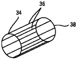
本実施形態の1つでは、図2に示すバードケージコイル構造34は例示的な全身用コイルとして利用されている。当業者であれば理解するであろうように、こうしたコイル構造は長手方向導体36と導電性端部リング38とを含んでいる。これらの導体に印加するパルスは所望の周波数(例えば、64MHz)で駆動させ、RFコイル32の特定のモードを励起させている。
【0025】
ここで再度図1に示す実施形態を参照すると、RFコイル32は受信コイルの役割も果たしている。したがって、RFコイル32は、パッシブ・モードやアクティブ・モードにおいて、磁気回転材料からの放出を受信するため並びに無線周波数励起パルスを印加するために、それぞれ駆動用及び受信用回路と結合させることがある。別法として、RFコイル32から分離しているような受信コイルの様々な構成を提供することができる。こうしたコイルは、頭部コイル・アセンブリなど、目的の解剖部位に特に適合した構造を含むことがある。さらに、受信コイルは、フェーズドアレイ・コイルその他を含め適当な任意の物理的構成で設けることができる。無線周波数シールド40(例えば、図4参照)は、傾斜コイル26、28及び30の間に配置させて、動作時に傾斜コイルのうちの幾つかの存在からRFコイル32を遮蔽することができる。詳細には、RFシールド40は、以下で検討するようにしてRF磁場が傾斜コイルのうちの幾つかに入り込むのを防止している。この入り込みがあるとRFコイル32の効率にマイナスの影響が及ぶことになる。
【0026】
本構成の1つでは、傾斜コイル26、28及び30は、イメージング・システム10内でのそれぞれの機能に適合するような異なる物理的構成を有する。当業者であれば理解するであろうように、これらのコイル26、28及び30は、導電性のワイヤ、バーまたはプレートから構成されており、これらは、以下に説明するような制御パルスが印加されると傾斜磁場を発生させるコイル構造を形成するように、巻き付けられたり切り離されたりしている。傾斜コイル・アセンブリ内でこれらのコイルは幾種類かの順序で配置することができるが、本実施形態では、最内側の位置にZ軸コイルを配置し、概して非対称のソレノイド様構造を形成させている。したがって、図示した実施形態では、傾斜コイル30はZ軸ソレノイド・コイルであり、一方コイル26及び28はそれぞれY軸コイル及びX軸コイルである。本構成では、RFシールド40をZ軸コイル30とX軸コイル28の間に位置決めしている。
【0027】
スキャナ12のコイルは、所望の磁場及びパルスを生成すると共に磁気回転材料からの信号を制御された方式で読み取るように外部回路により制御している。当業者であれば理解するであろうように、典型的には患者の組織内にある材料に主磁場が加えられると、組織内の常磁性の原子核の個々の磁気モーメントはこの主磁場と部分的に整列する。正味の磁気モーメントは偏向磁場の方向に生成されるが、垂直な面内でランダムな向きをもつ磁気モーメントの成分は全体として互いに相殺される。検査シーケンスの間に、関心対象材料のラーモア周波数またはその近傍の周波数でRF周波数パルスを発生させ、これにより、正味の横方向磁気モーメントを生成するような正味の整列磁気モーメントの回転が生じる。この横方向磁気モーメントは主磁場方向の周りで歳差運動し、スキャナにより検出され処理されて所望の画像を再構成させるためのRF信号が放出される。
【0028】
傾斜コイル26、28及び30は、典型的には正極性と負極性とをもつようにその強度を事前定義の撮像域全体にわたって変化させているような、精度よく制御された磁場を発生させる役割を果たしている。各コイルを周知の電流により付勢させると、得られる磁場傾斜は主磁場と重ね合わされ、磁場強度のZ軸成分の撮像域全体にわたる望ましくは直線的な変動を生成させる。この磁場は1つの方向では直線的に変化するが、他の2方向では均一である。これら3つのコイルは、その変化方向に関して互いに直交した軸を有しており、これにより、3つの傾斜コイルを適当に組み合わせて任意の方向をもつ直線的な磁場傾斜を印加することができる。
【0029】
このパルス状の傾斜磁場により撮像処理に不可欠な様々な機能が実行される。これらの機能のうちの幾つかとしては、スライス選択、周波数エンコード及び位相エンコードがある。これらの機能は、元の座標系に関するX軸、Y軸及びZ軸に沿うか、あるいは個々の磁場コイルに印加されるパルス状電流の組み合わせにより決定される別の軸に沿って印加することができる。
【0030】
スライス選択傾斜により撮像しようとする患者の組織または解剖構造に対するある厚み(slab)が決定される。スライス選択傾斜磁場は、周波数選択RFパルスと同時に印加し、所望のスライス内で同じ周波数で歳差運動するような既知のボリュームをもつスピンを励起させている。このスライス厚は、RFパルスのバンド幅及び撮像域全体にわたる傾斜強度により決定される。
【0031】
周波数エンコード傾斜は読み出し傾斜としても知られており、通常はスライス選択傾斜と直角の方向に印加する。一般に、周波数エンコード傾斜はRF励起から得られるMRエコー信号の形成前や形成中に印加する。磁気回転材料のスピンは、この傾斜の影響下において傾斜磁場に沿った空間的位置に従った周波数エンコードを受ける。収集した信号は、フーリエ変換によって解析し、選択したスライス内での位置が周波数エンコードにより特定される。
【0032】
最後に、位相エンコード傾斜は一般に、読み出し傾斜の前でスライス選択傾斜の後に印加される。位相エンコード方向での磁気回転材料内のスピンの位置特定は、データ収集シーケンス中に順次印加する傾斜振幅を若干異ならせて用いることにより、その材料の歳差運動しているスピンの位相に順次差違を導入することにより実現させる。この位相エンコード傾斜により、位相エンコード方向での位置に従って材料のスピン間に位相差を生成することができる。
【0033】
当業者であれば理解するであろうように、上述の例示的な傾斜パルス機能、並びに本明細書に明示的には記載していないその他の傾斜パルス機能を利用しているパルスシーケンスのためには、多種多様な方式を考案することができる。さらに、このパルスシーケンスの適応によって、選択したスライスと周波数及び位相エンコードとの両方を適当な方向に向けて、所望の材料を励起させると共に生じたMR信号を収集して処理することができる。
【0034】
スキャナ12のコイルは、所望の磁場及び無線周波数パルスを生成させるようにスキャナ制御回路14により制御される。スキャナ制御回路14は、検査中に利用するパルスシーケンスに指令するため、並びに受信した信号を処理するために1つまたは複数の制御回路を含むことがある。この制御回路は、汎用または特定用途向けのコンピュータからなるCPUやディジタル信号プロセッサなど適当な任意のプログラム可能な論理デバイス、並びにメモリ回路を含むことがある。このメモリ回路は典型的には、スキャナにより実施する検査シーケンスの間に使用される物理的及び論理的な軸構成パラメータ、検査パルスシーケンス記述、収集した画像データ、プログラミング・ルーチンその他を記憶するのに適したタイプである。スキャナ制御回路14はさらに、制御回路とスキャナ12のコイルとの間のインタフェースを可能にしている増幅/制御回路及び送信/受信回路を含むことがある。最後に、スキャナ制御回路14は、構成及び画像データをシステム制御回路16とやり取りするためのインタフェース要素を含んでいる。
【0035】
システム制御回路16は、オペレータまたは放射線医とスキャナ12との間でのスキャナ制御回路14を介したインタフェースを容易にするための広範なデバイスを含むことがある。例えば、オペレータ・コントローラは、汎用または特定用途向けのコンピュータを利用しているコンピュータ・ワークステーションの形態で設けることができ、このワークステーションは、パルスシーケンス記述、検査プロトコル、または患者及び画像データを記憶することができる。ワークステーションはさらに、ローカルとリモート両方でのデータやり取りのために様々なインタフェースや周辺ドライバ(peripheral drivers)を含むことがある。典型的な入力はキーボードまたはマウスを介して達成することができる。典型的な出力はプリンタやコンピュータ・モニタ48を介することができる。追加的なデータのやり取りとしては、医用画像管理システム(PACS)、遠隔放射線システム(teleradiology system)など、ローカル式及び遠隔式の画像検索及び検査制御デバイスを含むことがある。
【0036】
一般に、MRIシステムで実施されるパルスシーケンスは、制御回路14内に記憶してある機能的及び物理的構成の組とパラメータ設定との両者により規定される。一例として、図3は、図1に示すようなシステム上で実施できる典型的なパルスシーケンスを図示している。その検査の種類に応じて様々な多くのパルスシーケンス定義が実施可能であるが、図3の例では、定常状態モード(GRASS)のパルスシーケンスでの傾斜型(gradient recalled)収集は、互いに適当なタイミング調整とした一連のパルス及び傾斜により規定されている。全体を参照番号66で示しているこのパルスシーケンスはしたがって、スライス選択軸68、周波数エンコード軸70、位相エンコード軸72、RF軸74及びデータ収集軸76上の各パルスにより規定される。一般に、パルスシーケンス記述は、参照番号78で表すようにスライス選択軸68上の一対の傾斜パルスで開始される。これらの傾斜パルスの第1のパルスの間に、被検体内の磁気回転材料を励起させるようなRFパルス80が生成される。次いで、位相エンコード・パルス82が生成され、続いて周波数エンコード傾斜84が生成される。データ収集ウィンドウ86により位相及び周波数エンコードを受けた励起パルスから得られる信号を検知することができる。パルスシーケンス記述は、スライス選択軸、周波数エンコード軸及び位相エンコード軸上のさらに別の傾斜パルスにより終了する。
【0037】
上述した例示的シーケンスなどの検査シーケンスの間に、RFコイルと傾斜コイルの間のRFカップリングなどの電磁相互作用がシステムの動作に悪影響を与えることがある。例えば、傾斜コイル(特に、X軸及びY軸のコイル)があるためにRFコイルの直列抵抗が増加し、誘導性及び容量性カップリングによってその周波数が変化することがある。さらに、RFコイルの効率及び信号対雑音比が損なわれることがある。こうした相互作用はまた、傾斜コイルを構成している損失性材料に貫通させたままにするとRF磁場にも大きな影響を及ぼすことがある。詳細には、X軸コイル26及びY軸コイル28は、RF磁場が傾斜コイルのこれらの領域に貫通したままである場合、RF磁場と強い相互作用を起こすことが知られている。これにより、RFコイルに望ましくないRF損失や性能(効率及びQ値(共通性能基準))の低下が生じる。この問題の解決法の1つは、図4に示すように、傾斜コイル・アセンブリ内の中間位置にRFシールド40を配置させることである。
【0038】
図4を参照すると、コイル・アセンブリ88は、上述した内側傾斜コイル26、28及び30と、最内側の傾斜コイル30とそのすぐ隣りの傾斜コイル28の間に配置したRFシールド40と、を含んでいる。本実施形態の1つでは、最内側の傾斜コイル30は、Z軸コイルなど修正ソレノイド型のコイルである。RFシールド40は、銅などの導体材料からなる1枚または複数枚の薄肉シートなど、適当な任意の形態のシールドとすることがある。代替的形態のRFシールドを具体的なスキャナ構造に適合させることもできる。こうしたスキャナ構造の例としては、円筒構造や、開放型MRIシステムで使用される構造などの平面構造が含まれる。しかし、これらの各場合において、そのRFシールド40は傾斜コイル内に配置させ、ソレノイド型コイルすなわちZ軸コイル30に対する横方向RF磁場の影響が比較的軽微となるようにすると共に、RFコイル32から好都合に遠ざけた距離にシールドを位置決めしている。
【0039】
上で指摘したように、本技法によれば、上述した位置に適当な任意の形態のRFシールド40を設けることができる。例えば、このシールド40は、少なくとも図示した円筒状配置において、RF周波数では貫通不可能な中実の円筒として実現すると効果的である。しかし、このシールド40は、シールド40を傾斜磁場に対してより透明とさせるような開口または間隙を含むことがある。これらの開口または間隙は一般に、RF磁場に対するシールド効果ができるだけ十分に保全されるように設計する。このシールド40はまた、その層間にキャパシタンスをもつ材料からなる複数の層を含み、動作時に利用するRF周波数においてシールド40が中実のシールドのような役割を果たすようにすることがある。別の実現形態では、シールド40がRF周波数では反射するが傾斜磁場に関しては透明のままであるようにそのメッシュの大きさ及び厚さを選択した単一層の銅メッシュによりそのシールド40を形成させることがある。
【0040】
図4に示す本実施形態では、内側の各傾斜コイルの先に外側の各傾斜コイルを設けている。図4で参照番号92、94及び96で表しているこれらの外側傾斜コイルは、傾斜コイル構造体の残りの部分を形成している。外側傾斜コイルの役割は傾斜円筒アセンブリの外側の領域における傾斜磁場をできる限り打ち消し、クライオスタット構造の構成要素やマグネット構造の他の金属部分との相互作用を最小限とすることにある。当業者であれば理解するであろうように、コイル構造体の各傾斜コイルは、ガラス繊維・合成樹脂複合材製円筒などの支持構造体上に支持した1つまたは複数の導電性素子を含む。
【0041】
傾斜コイル26及び28はパルスシーケンスで利用するRF周波数では極めて損失を起こしやすいため、RFシールド40によりこれらのコイルに対するRF磁場の貫通を防止または大幅に低下させ、これによりエネルギーの損失を回避している。コイル・アセンブリ88内でコイル28とコイル30の間にRFシールド40を配置することによってRFコイル32とシールド40の間の距離が増加することに留意すべきである。RFコイル32とシールド40の間の距離を増加させると、所望の磁場強度を得るためにRFコイルに供給するエネルギー量を減らすことができる。さらに、RFシールドを傾斜コイル間の中間の位置に通してRFコイルから離すことにより、信号対雑音比及び効率の大幅な改善を得ることができる。したがって、システムに縮小サイズのRF増幅器を設けることができ、従来から知られたシステムにおいてRFエネルギーが大きいことに関連する問題が回避される。
【0042】
さらに、RFシールド40を傾斜コイル・アセンブリ88内に配置することによって、傾斜コイルの効率が向上する。詳細には、この構成では磁場系の長軸方向中心線からの距離を短縮させて主傾斜コイルを配置することができ、このため傾斜コイルの効率が改善される。実際に、傾斜コイルの効率は、主傾斜巻き線と遮蔽用傾斜巻き線の間の距離に対して極めて敏感である。したがって、主傾斜コイルと長軸方向中心線の間の距離を短縮することによって、3つの傾斜コイルすべての主巻き線と遮蔽用巻き線の間の距離を増加させることができ、これにより3つのすべての傾斜コイル・アセンブリの効率が大幅に改善する。
【0043】
当業者であれば理解するであろうように、Z軸コイル30は、RFシールド40の内方に位置しており、図5に示すように、横断中心面の両側の周りで長さ方向に距離(すなわち、ピッチ)を変化させるような間隔としたソレノイド導体の累進的周回を有する修正巻き式ソレノイドコイルとしてその全体を形成させている。さらに、巻き付け方向は横断中心面の両側で反転させ、横方向XY面に対して対称性の鏡像構造を生成させている。したがって、コイル30は、円筒状の支持構造体110上に支持された銅製のワイヤ、ロッドまたはバーなどの巻き線導体108を含んでいる。
【0044】
実際には、上述の技法は多くのMRイメージング・システムで適正に機能する。しかし、超短尺円筒状マグネットを組み込んだシステムでは、Z軸コイル導体を従来式で巻き付けると様々な問題を生じることがある。こうした超短尺システムを、非短尺システムと比較してZ軸傾斜コイル30を備える巻き線導体108の介在巻き線間隔が短縮していること、並びにピッチ間のばらつきが減少していることを図示した図6に示している。図示したタイプの超短尺システムでは、その介在巻き線間隔を1.5mmの範囲内とすることがある。介在巻き線間隔のこの大幅な短縮はパワー効率及び傾斜磁場の直線性を維持するために必要である。しかし、こうした超短尺システムでは高密度巻き付けによってパワー効率は上昇するが、この際シールドを介在させないとZ軸傾斜コイル30とバードケージRFコイル34とで十分なデカップリングを得ることが困難となる。
【0045】
ビオ・サバール計算によって、理論的には、バードケージRFコイル34とZ軸傾斜コイル30の間にコイルの構成による誘導性カップリングは生じないはずであることが確認される。詳細には、バードケージRFコイル34は本来、半径方向にRF磁場を生成させるもので、コイルを覆うように一体化してもZ軸方向では正味の磁束は発生させない。Z軸傾斜コイル30では、その電流分布は原点の周りに非対称である。したがって理論上は、バードケージRFコイル34がZ軸傾斜コイル30の内部で半径方向及び長手方向の中心に位置していれば、バードケージRFコイル34はZ軸傾斜コイル30などのソレノイド状コイルと誘導性にカップリングすることはない。しかし超短尺システムでは、バードケージ端部リング38の導体と巻き付けた傾斜導体108の間の距離がわずか10mm程度となることがあり、事実上実際には不可能な数分の1ミリメートルの整列精度を要求されることがある。整列不良となると、バードケージRFコイル34とZ軸傾斜コイル30の間に残留カップリングが生じ、品質係数(すなわち、Q)が低くなり、効率が対応して損なわれることにつながる。したがって、Z軸傾斜コイル導体108は、バードケージRFコイル34とZ軸傾斜コイル30の間の相互作用が最小となるように最適に巻き付けることが望ましい。
【0046】
図6を参照すると、Z軸傾斜コイル30の従来式の巻き付けに関する2つの点がバードケージRFコイル34のQ低下の原因となっていることが分かっている。先ず、バードケージRFコイル34の端部リング38の上側に配置した巻き線導体108の一部分が残留カップリングを生じさせ、このためシステムに関連するQが低下する。ここで図7を参照すると、各端部リング38の上に端部リング・ギャップ114を存在させるようにしてZ軸傾斜コイル30を巻きつけることによってこの問題に対処している。この場合、バードケージRFコイル34のQは端部リング・ギャップ114の幅の関数として測定する。ギャップ配線116は、ギャップ114の両側で巻き線導体108の一部分を接続させるために端部リング・ギャップ114に跨っている。ギャップ配線116は任意の構成とすることができるが、実施の一形態では、その構成は直線状である。この直線的構成によれば、ギャップ114の上にあるギャップ配線116を最短としてギャップ114を橋渡しすることができ、この直線的構成が図7に示す実施形態となっている。ギャップ114上に最短のギャップ配線116を設けることにより、バードケージRFコイル34のQに対する悪影響が最小限になるものと考えられる。ギャップ114は、端部リング38と比べてより幅狭のことやより幅広のことがあるが、実施の一形態では、1インチ幅の端部リング38と2インチ幅のギャップ114により受容可能な成果を得られることが分かっている。
【0047】
さらに図6を再度参照すると、Z軸傾斜コイル30の対称な正部分と負部分を接続している直線状接続体配線112によって、バードケージRFコイル34のQは接続用配線の方位位置(azimuthal position)に伴った変化を受ける。詳細には、Z軸傾斜コイル30の対称部分同士を接続するために直線状配線を使用すると、バードケージRFコイル34は所望の円偏向磁場ではなく楕円偏向磁場を発生させる結果となる。このため、接続体配線112がラング36の上を1回通過するごとにQが低下するようにして、バードケージラング36と接続体配線112との角度に従ってQが変化することになる。
【0048】
ここで再度図7を参照すると、この問題に対しては、アイソセンタを横切るZ軸傾斜コイル30の正部分と負部分をスパイラル巻き接続体118を用いて接続することにより対処している。スパイラル巻き接続体118により生じるバードケージRFコイル34とZ軸傾斜コイル30の間の任意のカップリングはバードケージRFコイル34のラング36間で均等に分布する。図7はRFコイル34を1回取り巻いて次いで反転しているスパイラル巻き接続体118を表しているが、当業者であれば、スパイラル巻き接続体118は単に、反転の前に半回転や、半回転の任意の倍数の回転(すなわち、180°、360°、540°、720°)を受けていることを理解するであろう。傾斜コイル30における半回転スパイラルのこうした使用は、相対するラングが電流振幅は同じであるが180度の位相差を有するように動作する傾向にあるためRFコイル34の均一モードと組み合わせると実現可能であり、これによってあらゆるカップリングはすべてのラング間に分散される。スパイラル巻き導体118を使用しているため、バードケージRFコイル34のQを変化させることなくZ軸傾斜コイル30とバードケージRFコイル34のいずれかをZ軸の周りに回転させることができる。こうした巻き線技法を使用するとバードケージRFコイル34に関連する高いQ係数が保持される一方、超短尺システムで傾斜埋め込み式シールドの使用が可能となる。
【0049】
本発明は様々な修正形態や代替形態とする余地があるが、具体的な実施形態を一例として図面に示すと共に本明細書で詳細に記載してきた。しかし、本発明を開示した特定の形態に限定しようとする意図ではないことを理解されたい。むしろ、本発明は、添付の特許請求の範囲で規定した本発明の精神及び趣旨に属するすべての修正形態、等価形態、代替形態に及ぶものである。
【図面の簡単な説明】
【図1】本シールド技法のある種の態様を実現している、医用診断イメージングで使用するためのMRIシステムの図である。
【図2】例示的な全身用RFコイルを表した図である。
【図3】図1のシステムで実施できるようなMRI検査の例示的なパルスシーケンス記述を表したグラフである。
【図4】傾斜コイル及び傾斜コイル間のRFシールドのレイアウトを表した図である。
【図5】全身用コイル構造で使用できる例示的なZ軸傾斜コイルの図である。
【図6】従来のシステムで周知であるような、RFコイルの周りに配置したZ軸傾斜コイルの側面図である。
【図7】本技法のある種の態様に従ってRFコイルの周りに配置したZ軸傾斜コイルの側面図である。
【符号の説明】
10 磁気共鳴イメージング(MRI)システム
12 スキャナ
14 スキャナ制御回路
16 システム制御回路
18 患者ボア
20 寝台
22 患者
24 主マグネット・コイル
26 傾斜コイル
28 傾斜コイル
30 傾斜コイル、Z軸コイル
32 無線周波数(RF)コイル
34 バードケージコイル構造
36 バードケージラング、長手方向導体
38 端部リング
40 無線周波数(RF)シールド
66 パルスシーケンス
68 スライス選択軸
70 周波数エンコード軸
72 位相エンコード軸
74 RF軸
76 データ収集軸
78 傾斜パルス
80 RFパルス
82 位相エンコード・パルス
84 周波数エンコード傾斜
86 データ収集ウィンドウ
88 コイル・アセンブリ
88 傾斜コイル・アセンブリ
92 外側傾斜コイル
94 外側傾斜コイル
96 外側傾斜コイル
108 巻き線導体、傾斜導体
110 円筒状支持構造体
112 接続体配線
114 端部リング・ギャップ
116 ギャップ配線
118 スパイラル巻き接続体[0001]
TECHNICAL FIELD OF THE INVENTION
The present invention relates generally to the field of medical diagnostic imaging. The invention relates more particularly to magnetic resonance imaging and noise reduction in magnetic resonance imaging systems incorporating ultrashort cylindrical magnets.
[0002]
BACKGROUND OF THE INVENTION
Magnetic resonance imaging (MRI) systems are widespread in the medical diagnostics field. Over the past two decades, improved techniques for MRI examinations have been developed, which can now produce extremely high quality images in a relatively short time. As a result, the radiologist can utilize diagnostic images of varying degrees of resolution to suit a particular diagnostic application.
[0003]
In general, MRI examinations are based on the interaction of nuclear magnetic spins in a subject between a main magnetic field, a radio frequency (RF) magnetic field and a time-varying gradient magnetic field. Certain components of the nucleus, such as the hydrogen nucleus in the water molecule, exhibit characteristic behavior in response to an external magnetic field. The spin precession of these nuclear components is affected by the manipulation of these magnetic fields, and an RF signal can be obtained, which can be detected and processed and used to produce a useful image.
[0004]
Magnetic fields used to create images in MRI systems include extremely uniform static magnetic fields generated by the main magnet. A series of gradient magnetic fields is generated by a coil set consisting of three gradient coils arranged around the subject. These gradient fields encode the position of individual volume elements (ie, voxels) in three dimensions. A radio frequency coil is used to generate the RF magnetic field. This RF field disturbs the spin system from the equilibrium direction, so that the spins precess about the axis of their equilibrium magnetization. During this precession, the spin emits a radio frequency magnetic field, which is either by the same transmit RF coil (typically a birdcage resonator) or by another receive-only coil. Is detected by These signals undergo amplification, filtering, and digitization. The digitized signal is then processed using one of several reconstruction algorithms capable of useful image reconstruction.
[0005]
Many techniques have been specifically developed to acquire MR images for a variety of applications. One of the major differences between these techniques concerns how to use gradient and RF pulses to manipulate the spin system to obtain different image contrast, signal to noise ratio and resolution. These techniques are illustrated as "pulse sequences", which are graphs depicting the pulses along the temporal relationship between the pulses. In recent years, pulse sequences have been developed that allow very fast collection of large amounts of raw data. With such a pulse sequence, the time required to perform the inspection is significantly reduced. Reducing the time is particularly important for acquiring high-resolution images and for reducing the effects of body movement and reducing discomfort for the patient being examined.
[0006]
While magnetic field interactions are important in encoding data collected by an MRI system, certain magnetic field interactions are undesirable or may lead to degradation of image data. For example, if an appropriate pulse is applied to the RF coil during a test sequence, the RF energy from the RF coil can penetrate the gradient coil structure and induce eddy currents into the gradient coil structure that cause losses. , Its energy may be consumed. Further, to maintain high efficiency of the RF coil, an RF shield is typically placed between the RF coil and gradient coil set to prevent or reduce RF magnetic fields from penetrating all of the gradient coil. Let me. The RF shield is designed to minimize eddy current generation by making the RF shield substantially transparent to the gradient field by switching the gradient field. At the same time, these RF frequencies are considerably higher than the characteristic eddy current extinction rate in the shield, thereby causing the shield to act as a penetration barrier to RF magnetic fields. However, because the RF shield is close to the RF coil conductor (particularly for whole body RF transmit coils), it can have a significant effect on the overall power efficiency and signal-to-noise ratio of the RF coil. Therefore, it is generally desirable to place the RF shield as far as possible from the RF coil.
[0007]
To address these issues, the RF shield is placed between the gradient coils so that the Z-axis gradient coil (typically a coil of an asymmetric solenoid type with various pitches) is within the shield range (ie, the shield and the RF (Between transmission coils). This configuration is possible because the mode of the RF coil typically used in MRI has little or no net magnetic flux in the Z-axis, thus minimizing the coupling between the RF coil and the Z-axis gradient coil. Depending on In this configuration, the Z-axis gradient coil is present inside the shield surface and the RF shield can be moved far away from the transmit coil, so that the radio frequency magnetic field is essentially undisturbed, Significant noise reduction and increased efficiency are obtained.
[0008]
However, this configuration may not be acceptable in systems using ultra-short cylindrical magnets that significantly reduce the spacing between the windings of the Z-axis gradient coil. At this reduced spacing, there are many factors that prevent proper decoupling of the high-density gradient coil from the RF coil. First, in such a system, the distance between the RF coil conductor and the Z-axis inclined conductor is only about 10 mm, causing frequent misalignment in either the radial direction or the Z-axis direction. Coupling may occur between Z-axis gradient coils. Second, coupling occurs between the end-ring and the Z-axis tilt winding as the Z-axis tilt winding passes over the end ring of the birdcage resonator. Finally, the quality factor (Q) for the system is determined by the conductive "rungs" of the birdcage resonator and the connecting wires connecting the two asymmetric halves of the Z-axis gradient coil. Depends on the angle between. Specifically, the Q becomes smaller each time the connection wiring passes once above the birdcage rung.
[0009]
Therefore, there is a need for an improved technique for winding a Z-axis tilt. In order to address the shortcomings of previously known systems, in systems utilizing ultrashort cylindrical magnets and RF shields outside of the Z-axis gradient coil, the interaction between the Z-gradient and the birdcage RF whole-body coil has been described. There is a particular need for techniques that minimize the effects.
[0010]
[Means for Solving the Problems]
The present invention provides a Z-axis oblique winding technique designed to meet such needs. Although the technique can be used in a wide variety of systems, it is particularly suitable for magnetic resonance imaging systems that utilize ultrashort cylindrical magnets, such as those used in medical diagnostic applications. The technique can also be used with any suitable MRI scanner design, including whole body scanners, open scanners, and scanners with a range of magnetic field ratings. The technique, if supported, can be used for retrofitting existing scanners or can be incorporated into new designs, especially those relating to the configuration of gradient coil structures.
[0011]
The technique uses a new style of winding for the Z-axis gradient coil. In one embodiment, a gap is formed in the Z-axis gradient coil winding on each birdcage coil end ring. The gap is then crossed at a minimum distance using a straight connecting wire, thereby minimizing the coupling due to the end ring between the RF coil and the Z-axis gradient coil. In the second embodiment, the asymmetric halves of the Z-axis gradient coil are connected to each other across the isocenter using a spirally wound connection body. The spiral winding of the connection distributes any coupling resulting from this connection between all rungs of the birdcage RF whole body coil. This technique has been demonstrated to significantly reduce the coupling between the Z-axis gradient coil and the RF coil when the Z-axis gradient coil and the RF coil are placed radially inside the RF shield.
[0012]
In one aspect of the present invention, a system is provided that utilizes a new style of gradient coil winding. The system includes an RF coil consisting of an end ring with a rung therebetween and a gradient coil disposed about the RF coil. The gradient coil comprises a gradient conductor wound as a solenoid coil, and the gradient coil is wound with a gap in the winding above each end ring of the RF coil where a portion of the conductor intersects. I have.
[0013]
In another aspect of the invention, one system is provided that utilizes a new style of gradient coil winding. The system includes an RF coil consisting of an end ring with a rung therebetween and a gradient coil disposed about the RF coil. The gradient coil includes a gradient conductor wound as a symmetric solenoid coil around an isocenter of a gradient magnetic field generated by the gradient coil, and is connected by one symmetric spiral winding connection wire formed by one segment of the gradient conductor. Thus, the positive half and the negative half of the symmetric solenoid coil exist.
[0014]
In another aspect of the invention, one system is provided that utilizes a new style of gradient coil winding. The system has an inner cylinder formed by a birdcage RF coil with a pair of end rings connected by spaced rungs. The system further includes a conductive element disposed about the inner cylinder and wound to form a solenoid coil having a gap above each end ring where a minimum amount of the conductive element intersects. It also has an outer cylinder such as that formed by a gradient coil. The winding of the solenoid coil is inverted in a cross section that bisects the coil, and a symmetrical spiral winding segment in which the conductive element that intersects the cross section orbits the inner cylinder in multiples of half a circle before inversion It is to be.
[0015]
In another aspect of the invention, the winding is reversed at the isocenter position of the magnetic field generated by the gradient coil, prior to the reversal there is a first winding and following the reversal a second winding is provided. A gradient coil is provided having a conductor wound as a solenoid coil in which a wire is present. The transition from the first winding to the second winding is achieved by a spiral wound segment of the conductor passing around the whole body RF coil at least half a circle before inversion.
[0016]
In another aspect of the invention, the winding is reversed at the isocenter position of the magnetic field generated by the coil, with a first winding prior to the reversal and a second winding following the reversal. And a coil having a conductor wound as a solenoid coil. The winding of the coil includes a pair of gaps, one on each side of the isocenter, each of which has a solenoid coil wound above a pair of end rings of the underlying whole body RF coil. It is arranged not to be. A minimal amount of conductive material intersects each gap.
[0017]
In another aspect of the present invention, a method for winding a gradient coil is provided that reduces coupling between the gradient coil and the RF coil. The method comprises the steps of: wrapping a conductor around an RF coil to form a solenoid coil; and forming the conductor in a spiral as it approaches a desired isocenter position for the gradient magnetic field generated by the gradient coil. The spiral includes a shaping operation such as passing around the RF coil in half-circumference increments before inversion. At the desired isocenter position, the winding of the solenoid coil is reversed to form a symmetric solenoid coil that includes a reversal spiral around the desired isocenter.
[0018]
In another aspect of the present invention, a method for winding a gradient coil is provided that reduces coupling between the gradient coil and the RF coil. The method includes the act of wrapping a conductor around the RF coil to form a solenoid coil, and within a portion of the solenoid coil disposed about an end ring of the RF coil to intersect a length of the conductor. Forming a gap. At a desired isocenter position, the winding of the solenoid coil is reversed to form a symmetric solenoid coil around the desired isocenter.
[0019]
In another aspect of the present invention, a magnetic resonance imaging system is provided. The magnetic resonance imaging system comprises an RF coil having two end rings connected by a rung, and a gradient coil disposed around an RF coil having a gradient conductor wound entirely as a symmetric solenoid coil. Wherein the winding of the solenoid coil includes a gradient coil that is inverted at a desired isocenter of the gradient magnetic field generated by the gradient coil. The system further includes means for decoupling a portion of the gradient coil from the underlying end ring.
[0020]
In another aspect of the present invention, a magnetic resonance imaging system is provided. The magnetic resonance imaging system comprises an RF coil having two end rings connected by a rung, and a gradient coil disposed around an RF coil having a gradient conductor wound entirely as a symmetric solenoid coil. Wherein the winding of the solenoid coil includes a gradient coil that is inverted at a desired isocenter of the gradient magnetic field generated by the gradient coil. The system further includes means for distributing the coupling between the rung and the RF coil such that any coupling between the RF coil and the RF coil is substantially evenly distributed between the rungs.
[0021]
These and other advantages and features of the present invention will become apparent from the following detailed description when read in conjunction with the drawings.
[0022]
BEST MODE FOR CARRYING OUT THE INVENTION
Turning now to the drawings, and referring first to FIG. 1, a magnetic resonance imaging (MRI)
[0023]
[0024]
In one embodiment, the
[0025]
Referring again to the embodiment shown in FIG. 1, the
[0026]
In one of the present configurations, the gradient coils 26, 28 and 30 have different physical configurations to accommodate their respective functions within the
[0027]
The coils of the
[0028]
The gradient coils 26, 28 and 30 are responsible for generating a precisely controlled magnetic field whose intensity is typically varied over a predefined imaging area so as to have positive and negative polarities. Plays. When each coil is energized with a known current, the resulting magnetic field gradient is superimposed on the main magnetic field, producing a preferably linear variation of the Z-axis component of the magnetic field strength over the imaging field. This field varies linearly in one direction, but is uniform in the other two directions. These three coils have axes orthogonal to each other with respect to their changing directions, so that a linear magnetic field gradient having an arbitrary direction can be applied by appropriately combining the three gradient coils.
[0029]
Various functions indispensable for the imaging process are executed by the pulse-like gradient magnetic field. Some of these functions include slice selection, frequency encoding, and phase encoding. These functions can be applied along the X, Y and Z axes relative to the original coordinate system, or along another axis determined by a combination of pulsed currents applied to the individual field coils. it can.
[0030]
The slice selection gradient determines a certain slab for the tissue or anatomy of the patient to be imaged. The slice-selective gradient magnetic field is applied simultaneously with the frequency-selective RF pulse to excite spins with a known volume that precess at the same frequency in the desired slice. This slice thickness is determined by the bandwidth of the RF pulse and the gradient intensity over the entire imaging area.
[0031]
The frequency encoding gradient, also known as the readout gradient, is usually applied in a direction perpendicular to the slice selection gradient. Generally, the frequency encoding gradient is applied before and during the formation of the MR echo signal obtained from the RF excitation. Under the influence of this gradient, the spins of the gyromagnetic material undergo frequency encoding according to their spatial position along the gradient field. The collected signal is analyzed by Fourier transform, and the position in the selected slice is specified by frequency encoding.
[0032]
Finally, the phase encoding gradient is generally applied before the readout gradient and after the slice selection gradient. The location of the spins in the gyromagnetic material in the phase encoding direction is determined by using a slightly different gradient amplitude applied sequentially during the data acquisition sequence to sequentially phase the precessing spins of the material. This is realized by introducing This phase encoding tilt allows a phase difference to be created between the spins of the material according to the position in the phase encoding direction.
[0033]
As those skilled in the art will appreciate, for pulse sequences utilizing the exemplary gradient pulse function described above, as well as other gradient pulse functions not explicitly described herein. Can devise a wide variety of methods. Further, the adaptation of this pulse sequence allows both the selected slice and both the frequency and phase encoding to be oriented appropriately to excite the desired material and collect and process the resulting MR signal.
[0034]
The coils of the
[0035]
[0036]
Generally, the pulse sequence implemented in the MRI system is defined by both the set of functional and physical configurations and parameter settings stored in the control circuit 14. As an example, FIG. 3 illustrates a typical pulse sequence that can be implemented on a system as shown in FIG. Many different pulse sequence definitions are feasible depending on the type of examination, but in the example of FIG. 3, gradient-recruited acquisition in a steady-state mode (GRASS) pulse sequence is suitable for each other. It is defined by a series of pulses and ramps for timing adjustment. This pulse sequence, generally indicated by
[0037]
During a test sequence, such as the exemplary sequence described above, electromagnetic interactions, such as RF coupling between the RF and gradient coils, can adversely affect the operation of the system. For example, the presence of gradient coils (especially the X and Y axis coils) increases the series resistance of the RF coil and may change its frequency due to inductive and capacitive coupling. Further, the efficiency and signal-to-noise ratio of the RF coil may be compromised. Such interactions can also have a significant effect on the RF magnetic field if left penetrating the lossy material making up the gradient coil. In particular, the X-axis coil 26 and the Y-
[0038]
Referring to FIG. 4, the
[0039]
As noted above, the techniques may provide any suitable form of
[0040]
In the present embodiment shown in FIG. 4, the outer gradient coils are provided before the inner gradient coils. These outer gradient coils, represented by
[0041]
Since the gradient coils 26 and 28 are very lossy at the RF frequencies utilized in the pulse sequence, the
[0042]
In addition, placing the
[0043]
As those skilled in the art will appreciate, the Z-
[0044]
In practice, the above described technique works properly in many MR imaging systems. However, in a system incorporating an ultrashort cylindrical magnet, various problems may occur when the Z-axis coil conductor is wound in a conventional manner. Such an ultrashort system is illustrated as having a reduced intervening winding spacing of the winding
[0045]
The Biot-Savart calculation confirms that theoretically, no inductive coupling due to the coil configuration should occur between the
[0046]
Referring to FIG. 6, it has been found that two points related to the conventional winding of the Z-
[0047]
Referring again to FIG. 6, the Q of the
[0048]
Referring again to FIG. 7, this problem has been addressed by connecting the positive and negative portions of the Z-
[0049]
While the invention is susceptible to various modifications and alternative forms, specific embodiments have been shown by way of example in the drawings and have been described in detail herein. It should be understood, however, that the intention is not to limit the invention to the particular forms disclosed. Rather, the invention is to cover all modifications, equivalents, and alternatives falling within the spirit and scope of the invention as defined by the appended claims.
[Brief description of the drawings]
FIG. 1 is an illustration of an MRI system for use in medical diagnostic imaging, implementing certain aspects of the present shield technique.
FIG. 2 illustrates an exemplary whole-body RF coil.
FIG. 3 is a graph illustrating an exemplary pulse sequence description of an MRI exam as can be performed with the system of FIG.
FIG. 4 is a diagram illustrating a layout of a gradient coil and an RF shield between the gradient coils.
FIG. 5 is an illustration of an exemplary Z-axis gradient coil that can be used in a whole-body coil configuration.
FIG. 6 is a side view of a Z-axis gradient coil positioned around an RF coil, as is known in conventional systems.
FIG. 7 is a side view of a Z-axis gradient coil positioned around an RF coil in accordance with certain aspects of the present technique.
[Explanation of symbols]
10 Magnetic resonance imaging (MRI) system
12 Scanner
14 Scanner control circuit
16 System control circuit
18 Patient bore
20 sleeper
22 patients
24 Main magnets and coils
26 gradient coil
28 gradient coil
30 Inclined coil, Z-axis coil
32 radio frequency (RF) coils
34 Bird cage coil structure
36 Birdcage rung, longitudinal conductor
38 End ring
40 Radio frequency (RF) shield
66 pulse sequence
68 Slice selection axis
70 Frequency encoding axis
72 phase encoding axis
74 RF axis
76 Data collection axis
78 tilt pulse
80 RF pulse
82 phase encode pulse
84 Frequency encoding gradient
86 Data Collection Window
88 Coil assembly
88 Gradient coil assembly
92 Outside gradient coil
94 Outside gradient coil
96 Outside gradient coil
108 winding conductor, inclined conductor
110 Cylindrical support structure
112 Connection body wiring
114 End ring gap
116 gap wiring
118 Spiral winding connector
Claims (41)
前記RFコイルの周りに配置されており、ソレノイドコイルとして巻き付けた傾斜導体を備えた傾斜コイルであって、該ソレノイドコイル内には該導体の一部分が交差する各端部リングの上側に1つのギャップが存在するような傾斜コイルと、
を備える磁気共鳴イメージング・システム。A radio frequency (RF) coil comprising two end rings connected by a plurality of rungs disposed perpendicular to the plane of the end rings;
A gradient coil disposed around said RF coil and comprising a gradient conductor wound as a solenoid coil, wherein a gap is provided within said solenoid coil above each end ring where a portion of said conductor intersects. And a gradient coil such that there is
A magnetic resonance imaging system comprising:
前記RFコイルの周りに配置されておりソレノイドコイルとして巻き付けた傾斜導体を備えた傾斜コイルであって、該傾斜コイルが傾斜導体の1つのセグメントによって接続されて対称なスパイラル巻き接続用配線を形成する正の半分と負の半分を含むように、該ソレノイドコイルは該傾斜コイルが形成する磁場のアイソセンタの周りに対称であるような該傾斜コイルと、
を備える磁気共鳴イメージング・システム。A radio frequency (RF) coil comprising two end rings connected by a plurality of rungs disposed perpendicular to the plane of the end rings;
A gradient coil disposed around said RF coil and having a gradient conductor wound as a solenoid coil, said gradient coil being connected by one segment of the gradient conductor to form a symmetric spiral winding connection wiring. The gradient coil including a positive half and a negative half, the solenoid coil being symmetrical about an isocenter of a magnetic field formed by the gradient coil;
A magnetic resonance imaging system comprising:
ソレノイドコイルを形成するように巻き付けた導電性素子を備えている、前記内筒の周りに配置して全体として1つの外筒を形成している傾斜コイルであって、該ソレノイドコイル内にはRFコイルの各端部リングの上側に1つのギャップが存在しており、かつ該ソレノイドコイルの巻き線は該コイルを2等分する横断面の位置で反転するようにして、各ギャップと交差するような最小量の導電性素子が使用されると共に、横断面と交差する該導電性素子は反転の前に半周の倍数単位で前記内筒を周回している対称なスパイラル巻きセグメントを備えているような傾斜コイルと、
を備える磁気共鳴イメージング・システム。A birdcage radio frequency (RF) coil comprising a pair of end rings connected by a plurality of spaced-apart rungs disposed at right angles to the plane of the end rings to form an overall inner cylinder; ,
A gradient coil comprising a conductive element wound to form a solenoid coil, disposed around the inner cylinder and forming an outer cylinder as a whole, wherein an RF coil is provided in the solenoid coil. There is one gap above each end ring of the coil, and the windings of the solenoid coil intersect each gap such that the windings are reversed at the position of the cross section bisecting the coil. A minimal amount of conductive element is used, and the conductive element intersecting the cross section is provided with a symmetric spiral wound segment orbiting the inner cylinder in multiples of half a circle before inversion. A gradient coil,
A magnetic resonance imaging system comprising:
ソレノイドコイルを形成するように前記RFコイルの周りに導体を巻き付ける動作と、
傾斜コイルが発生した傾斜磁場に関する所望のアイソセンタ位置に近づくに従ってスパイラル状に導体を形成する動作であって、該スパイラルは反転の前に半周の増分単位でRFコイルの周りを通過している形成動作と、
所望のアイソセンタの周りに対称なソレノイドコイルを形成させ該対称なソレノイドコイルの一部として逆向きのスパイラルを形成させるように、該所望のアイソセンタ位置で前記ソレノイドコイルの巻き線を反転させる動作と、
を含む方法。A method of winding a gradient coil that reduces coupling between a gradient coil and a radio frequency (RF) coil,
Wrapping a conductor around the RF coil to form a solenoid coil;
Forming a conductor in a spiral as the gradient coil approaches a desired isocenter position with respect to a gradient magnetic field, wherein the spiral passes around the RF coil in increments of half a circle before inversion. When,
Reversing the winding of the solenoid coil at the desired isocenter position so as to form a symmetric solenoid coil around the desired isocenter and form a reverse spiral as part of the symmetric solenoid coil;
A method that includes
ソレノイドコイルを形成するように前記RFコイルの周りに導体を巻き付ける動作と、
前記導体の長さ部分と交差するように、RFコイルの端部リングの周りに配置した前記ソレノイドコイルの一部分内にギャップを形成させる動作と、
傾斜コイルが発生させる傾斜磁場に関する所望のアイソセンタ位置で、該所望のアイソセンタの周りに対称なソレノイドコイルを形成させるように前記ソレノイドコイルの巻き線を反転させる動作と、
を含む方法。A method of winding a gradient coil that reduces coupling between a gradient coil and a radio frequency (RF) coil,
Wrapping a conductor around the RF coil to form a solenoid coil;
Forming a gap in a portion of the solenoid coil disposed about an end ring of an RF coil so as to intersect a length of the conductor;
At a desired isocenter position with respect to the gradient magnetic field generated by the gradient coil, an operation of reversing the winding of the solenoid coil so as to form a symmetric solenoid coil around the desired isocenter.
A method that includes
対称なソレノイドコイルとして全体に巻き付けた傾斜導体を備えているRFコイルの周りに配置した傾斜コイルであって、該ソレノイドコイルの巻き線は傾斜コイルが発生させる傾斜磁場の所望のアイソセンタを通る横断面との交点に対応した位置で反転しているような傾斜コイルと、
前記傾斜コイルの一部分をその下にある端部リングからデカップリングさせる手段と、
を備える磁気共鳴イメージング・システム。A radio frequency (RF) coil comprising two end rings connected by a plurality of rungs disposed perpendicular to the plane of the end rings;
A gradient coil disposed around an RF coil comprising a gradient conductor wound entirely as a symmetric solenoid coil, the winding of the solenoid coil having a cross section through a desired isocenter of a gradient magnetic field generated by the gradient coil. A gradient coil that is inverted at a position corresponding to the intersection with
Means for decoupling a portion of the gradient coil from an underlying end ring;
A magnetic resonance imaging system comprising:
対称なソレノイドコイルとして全体に巻き付けた傾斜導体を備えているRFコイルの周りに配置した傾斜コイルであって、該ソレノイドコイルの巻き線は傾斜コイルが発生させる傾斜磁場の所望のアイソセンタを通る横断面との交点に対応した位置で反転しているような傾斜コイルと、
前記傾斜導体のセグメントと前記RFコイルの間の任意のカップリングが前記ラング間で実質的に均等に分布するように該カップリングを該ラング間に分布させるための手段と、
を備える磁気共鳴イメージング・システム。A radio frequency (RF) coil comprising two end rings connected by a plurality of rungs disposed perpendicular to the plane of the end rings;
A gradient coil disposed around an RF coil comprising a gradient conductor wound entirely as a symmetric solenoid coil, the winding of the solenoid coil having a cross section through a desired isocenter of a gradient magnetic field generated by the gradient coil. A gradient coil that is inverted at a position corresponding to the intersection with
Means for distributing the coupling between the rungs such that any coupling between the segment of the inclined conductor and the RF coil is substantially evenly distributed between the rungs;
A magnetic resonance imaging system comprising:
Applications Claiming Priority (1)
| Application Number | Priority Date | Filing Date | Title |
|---|---|---|---|
| US10/138,858 US6885194B2 (en) | 2002-05-03 | 2002-05-03 | Method and apparatus for minimizing gradient coil and rf coil coupling |
Publications (3)
| Publication Number | Publication Date |
|---|---|
| JP2004000592A true JP2004000592A (en) | 2004-01-08 |
| JP2004000592A5 JP2004000592A5 (en) | 2008-07-24 |
| JP4307143B2 JP4307143B2 (en) | 2009-08-05 |
Family
ID=29215720
Family Applications (1)
| Application Number | Title | Priority Date | Filing Date |
|---|---|---|---|
| JP2003127031A Expired - Fee Related JP4307143B2 (en) | 2002-05-03 | 2003-05-02 | Method and apparatus for minimizing coupling between gradient coils and RF coils |
Country Status (3)
| Country | Link |
|---|---|
| US (2) | US6885194B2 (en) |
| EP (1) | EP1359429A3 (en) |
| JP (1) | JP4307143B2 (en) |
Cited By (3)
| Publication number | Priority date | Publication date | Assignee | Title |
|---|---|---|---|---|
| JP2008026003A (en) * | 2006-07-18 | 2008-02-07 | Jeol Ltd | Nmr probe |
| JP2009511232A (en) * | 2005-10-18 | 2009-03-19 | ターシオップ テクノロジーズ リミテッド ライアビリティ カンパニー | Method and apparatus for high gain nuclear magnetic resonance imaging |
| JP2019171028A (en) * | 2018-03-28 | 2019-10-10 | 国立研究開発法人量子科学技術研究開発機構 | Microstrip transmission line array rf coil, rf shield configuration, and integrated apparatus of rf coil and radiation imaging device |
Families Citing this family (22)
| Publication number | Priority date | Publication date | Assignee | Title |
|---|---|---|---|---|
| US7141974B2 (en) * | 2003-08-25 | 2006-11-28 | William A Edelstein | Active-passive electromagnetic shielding to reduce MRI acoustic noise |
| GB2409522B (en) * | 2003-12-22 | 2006-10-18 | Ge Med Sys Global Tech Co Llc | Gradient coil apparatus and method of assembly thereof |
| US7102350B2 (en) | 2004-06-30 | 2006-09-05 | General Electric Company | Shielding apparatus for magnetic resonance imaging |
| US20090289631A1 (en) * | 2004-12-21 | 2009-11-26 | Koninklijke Philips Electronics N.V. | Magnetic resonance imaging with multiple contrast |
| US8328862B2 (en) * | 2005-10-06 | 2012-12-11 | The Johns Hopkins University | MRI compatible vascular occlusive devices and related methods of treatment and methods of monitoring implanted devices |
| US7679364B2 (en) * | 2005-10-18 | 2010-03-16 | Tursiop Technologies Llc | Method and apparatus for high-gain magnetic resonance imaging |
| US7525310B2 (en) * | 2006-03-04 | 2009-04-28 | Raju Viswanathan | Signal acquisition and processing method and apparatus for magnetic resonance imaging |
| US7737693B2 (en) * | 2006-03-04 | 2010-06-15 | Tursiop Technologies Llc | Signal acquisition and processing method and apparatus for magnetic resonance imaging |
| US7375526B2 (en) * | 2006-10-20 | 2008-05-20 | Edelstein William A | Active-passive electromagnetic shielding to reduce MRI acoustic noise |
| DE102008006117B4 (en) * | 2008-01-25 | 2013-12-12 | Siemens Aktiengesellschaft | Magnetic resonance system, antenna system, method for setting up a magnetic resonance system and method for generating magnetic resonance images |
| JP5295799B2 (en) * | 2008-01-30 | 2013-09-18 | 株式会社東芝 | Gradient magnetic field coil, magnetic resonance imaging apparatus, and gradient magnetic field coil manufacturing method |
| US7576542B1 (en) * | 2008-06-26 | 2009-08-18 | General Electric Co. | System and apparatus for providing electrical and cooling interconnections in a magnetic resonance imaging (MRI) system |
| US7936170B2 (en) * | 2008-08-08 | 2011-05-03 | General Electric Co. | RF coil and apparatus to reduce acoustic noise in an MRI system |
| CN102713655B (en) * | 2009-12-02 | 2016-01-20 | 联邦科学与工业研究组织 | For the equipment of detection signal |
| US9261574B2 (en) | 2012-05-02 | 2016-02-16 | General Electric Company | Structured RF coil assembly for MRI scanner |
| US9498174B2 (en) | 2012-12-27 | 2016-11-22 | General Electric Company | Whole body RF coil for PET-MR system |
| US9116215B2 (en) | 2013-01-09 | 2015-08-25 | General Electric Company | Composite RF shield and method of making same |
| DE102013204952B3 (en) * | 2013-03-20 | 2014-05-15 | Bruker Biospin Ag | Active shielded cylindrical gradient coil system with passive RF shielding for NMR devices |
| US10473736B2 (en) | 2014-11-04 | 2019-11-12 | The General Hospital Corporation | Subject-loaded helical-antenna radio-frequency coil for magnetic resonance imaging |
| KR101664433B1 (en) | 2015-03-24 | 2016-10-10 | 삼성전자주식회사 | Magnetic resonance imaging apparatus and image processing method thereof |
| US10942235B2 (en) * | 2018-03-28 | 2021-03-09 | National Institutes For Quantum And Radiological Science And Technology | Microstrip transmission line array RF coil, RF shield configuration and integrated apparatus of RF coil and radiation imaging device |
| CN116520224B (en) * | 2023-05-09 | 2023-11-24 | 江苏力磁医疗设备有限公司 | Solenoid quadrature coil for magnetic resonance imaging |
Family Cites Families (26)
| Publication number | Priority date | Publication date | Assignee | Title |
|---|---|---|---|---|
| US500004A (en) * | 1893-06-20 | Fence-building machine | ||
| US704216A (en) * | 1898-08-22 | 1902-07-08 | Charles K Rosenberg | Account-book. |
| US4288049A (en) * | 1971-01-19 | 1981-09-08 | The United States Of America As Represented By The Secretary Of The Navy | Remote targeting system for guided missiles |
| US5147567A (en) * | 1971-04-09 | 1992-09-15 | The United States Of America As Represented By The Secretary Of The Navy | Synthetic lubricating oil greases containing metal chelates of Schiff bases |
| US4066819A (en) * | 1971-10-21 | 1978-01-03 | The United States Of America As Represented By The Secretary Of The Navy | Method of bonding gold films to non-electrically conducting oxides and product thereby obtained |
| US4617516A (en) | 1983-09-06 | 1986-10-14 | General Electric Company | Axial magnetic field gradient coil suitable for use with NMR apparatus |
| US5296810A (en) | 1992-03-27 | 1994-03-22 | Picker International, Inc. | MRI self-shielded gradient coils |
| US6516558B1 (en) * | 1997-03-19 | 2003-02-11 | Trece, Inc. | Insect trap and assembly for capturing and monitoring insects |
| US5990681A (en) * | 1997-10-15 | 1999-11-23 | Picker International, Inc. | Low-cost, snap-in whole-body RF coil with mechanically switchable resonant frequencies |
| US6147307A (en) * | 1998-10-22 | 2000-11-14 | Cooper Technologies Company | Side insertion trap |
| US6532695B1 (en) * | 2000-04-13 | 2003-03-18 | Richard Alvarado | Multiple bait structure insect trap |
| US6456076B1 (en) * | 2001-01-31 | 2002-09-24 | The Trustees Of The University Of Pennsylvania | Z gradient shielding coil for canceling eddy currents |
| US6498947B2 (en) * | 2001-02-23 | 2002-12-24 | Ge Medical Systems Global Technology Company, Llc | rf shielding method and apparatus |
| US6408567B1 (en) * | 2001-03-12 | 2002-06-25 | Knight Manufacturing Co., Inc. | Fishing lures and methods and molds for making same |
| DE60237438D1 (en) * | 2001-05-09 | 2010-10-07 | Panasonic Corp | INK JET AND METHOD OF MANUFACTURING AN ELECTRONIC COMPONENT WITH SUCH A DEVICE |
| US6678922B2 (en) * | 2001-07-06 | 2004-01-20 | Alan Elbert Comer | Bag closure or clamp made from pliable, resilient hose |
| US7546143B2 (en) * | 2001-12-18 | 2009-06-09 | Fuji Xerox Co., Ltd. | Multi-channel quiet calls |
| US6915814B2 (en) * | 2002-09-04 | 2005-07-12 | Dara Cheng | Transparent pipe trap with means of enhancing the biodegradation of sink effluents |
| ITVR20030060A1 (en) * | 2003-05-14 | 2004-11-15 | Ferplast Spa | FILTRATION DEVICE FOR AQUARIUMS |
| CA2534490C (en) * | 2003-08-08 | 2012-10-02 | Motivation Design Llc | Tire cover & carrier |
| US7042716B2 (en) * | 2003-08-25 | 2006-05-09 | Simon John Edward Shearman | Ergonomic pull-out computer housing |
| US7726063B2 (en) * | 2005-07-13 | 2010-06-01 | Arthur Graham Hawkins | Snake trap |
| US7327547B1 (en) * | 2006-01-20 | 2008-02-05 | Epstein Barry M | Circuit element and use thereof |
| US8331545B2 (en) * | 2008-12-11 | 2012-12-11 | International Business Machines Corporation | Handling communication session disconnection and reconnection |
| US8290124B2 (en) * | 2008-12-19 | 2012-10-16 | At&T Mobility Ii Llc | Conference call replay |
| US8373743B2 (en) * | 2009-03-13 | 2013-02-12 | Avaya Inc. | System and method for playing back individual conference callers |
-
2002
- 2002-05-03 US US10/138,858 patent/US6885194B2/en not_active Expired - Fee Related
-
2003
- 2003-05-01 EP EP03252776A patent/EP1359429A3/en not_active Withdrawn
- 2003-05-02 JP JP2003127031A patent/JP4307143B2/en not_active Expired - Fee Related
-
2005
- 2005-01-10 US US11/033,071 patent/US7109712B2/en not_active Expired - Fee Related
Cited By (3)
| Publication number | Priority date | Publication date | Assignee | Title |
|---|---|---|---|---|
| JP2009511232A (en) * | 2005-10-18 | 2009-03-19 | ターシオップ テクノロジーズ リミテッド ライアビリティ カンパニー | Method and apparatus for high gain nuclear magnetic resonance imaging |
| JP2008026003A (en) * | 2006-07-18 | 2008-02-07 | Jeol Ltd | Nmr probe |
| JP2019171028A (en) * | 2018-03-28 | 2019-10-10 | 国立研究開発法人量子科学技術研究開発機構 | Microstrip transmission line array rf coil, rf shield configuration, and integrated apparatus of rf coil and radiation imaging device |
Also Published As
| Publication number | Publication date |
|---|---|
| US20050134274A1 (en) | 2005-06-23 |
| EP1359429A3 (en) | 2005-04-20 |
| US6885194B2 (en) | 2005-04-26 |
| US20030206017A1 (en) | 2003-11-06 |
| EP1359429A2 (en) | 2003-11-05 |
| JP4307143B2 (en) | 2009-08-05 |
| US7109712B2 (en) | 2006-09-19 |
Similar Documents
| Publication | Publication Date | Title |
|---|---|---|
| JP4307143B2 (en) | Method and apparatus for minimizing coupling between gradient coils and RF coils | |
| US5198768A (en) | Quadrature surface coil array | |
| US7495443B2 (en) | RF coil system for super high field (SHF) MRI | |
| JP3779395B2 (en) | Magnetic resonance equipment | |
| US8125225B2 (en) | Transmit profile control in MRI | |
| US10031198B2 (en) | Methods and systems for a dual wind gradient coil | |
| JP2004526547A (en) | Transmit and receive coils for MR devices | |
| US6650118B2 (en) | RF coil system for an MR apparatus | |
| US20100060282A1 (en) | Three-dimensional asymmetric transverse gradient coils | |
| JP2003180659A (en) | Rf coil system for magnetic resonance imaging device | |
| DE102005020025A1 (en) | RF coil array for multi-channel MRI | |
| JPH0211122A (en) | High speed MRI using multiple receivers to generate multiple phase encoded data derived from a single NMR response | |
| JP4172939B2 (en) | RF shielding method and apparatus | |
| EP2132583B1 (en) | Coil decoupling | |
| CN104704383B (en) | Birdcage body coil for transmitted in parallel MRI | |
| US6522144B2 (en) | RF shielding method and apparatus for an open MRI system | |
| US8583213B2 (en) | Combined MR imaging and tracking | |
| US10295630B2 (en) | Gradient coil with variable dimension | |
| US8018232B2 (en) | Interleaved gradient coil for magnetic resonance imaging | |
| US6538442B2 (en) | MRI system having RF shielding gradient coil structure | |
| US8143893B2 (en) | Thin extended-cavity RF coil for MRI | |
| JP5258968B2 (en) | Magnetic resonance measuring device | |
| JPH05261081A (en) | Inspecting system using nuclear magnetic resonance | |
| US20240288521A1 (en) | Antenna assembly for a tomography system | |
| KR20110104807A (en) | Animal High Frequency Resonator |
Legal Events
| Date | Code | Title | Description |
|---|---|---|---|
| A521 | Written amendment |
Free format text: JAPANESE INTERMEDIATE CODE: A523 Effective date: 20060427 |
|
| A621 | Written request for application examination |
Free format text: JAPANESE INTERMEDIATE CODE: A621 Effective date: 20060427 |
|
| A521 | Written amendment |
Free format text: JAPANESE INTERMEDIATE CODE: A523 Effective date: 20080606 |
|
| A131 | Notification of reasons for refusal |
Free format text: JAPANESE INTERMEDIATE CODE: A131 Effective date: 20090203 |
|
| A521 | Written amendment |
Free format text: JAPANESE INTERMEDIATE CODE: A523 Effective date: 20090224 |
|
| A521 | Written amendment |
Free format text: JAPANESE INTERMEDIATE CODE: A523 Effective date: 20090316 |
|
| TRDD | Decision of grant or rejection written | ||
| A01 | Written decision to grant a patent or to grant a registration (utility model) |
Free format text: JAPANESE INTERMEDIATE CODE: A01 Effective date: 20090331 |
|
| A01 | Written decision to grant a patent or to grant a registration (utility model) |
Free format text: JAPANESE INTERMEDIATE CODE: A01 |
|
| A61 | First payment of annual fees (during grant procedure) |
Free format text: JAPANESE INTERMEDIATE CODE: A61 Effective date: 20090428 |
|
| R150 | Certificate of patent or registration of utility model |
Free format text: JAPANESE INTERMEDIATE CODE: R150 |
|
| FPAY | Renewal fee payment (event date is renewal date of database) |
Free format text: PAYMENT UNTIL: 20120515 Year of fee payment: 3 |
|
| FPAY | Renewal fee payment (event date is renewal date of database) |
Free format text: PAYMENT UNTIL: 20120515 Year of fee payment: 3 |
|
| FPAY | Renewal fee payment (event date is renewal date of database) |
Free format text: PAYMENT UNTIL: 20130515 Year of fee payment: 4 |
|
| LAPS | Cancellation because of no payment of annual fees |