GB2560777A - Electromagnetic assembly - Google Patents
Electromagnetic assembly Download PDFInfo
- Publication number
- GB2560777A GB2560777A GB1710640.2A GB201710640A GB2560777A GB 2560777 A GB2560777 A GB 2560777A GB 201710640 A GB201710640 A GB 201710640A GB 2560777 A GB2560777 A GB 2560777A
- Authority
- GB
- United Kingdom
- Prior art keywords
- coil assembly
- outer shield
- housing
- shield coil
- assembly
- Prior art date
- Legal status (The legal status is an assumption and is not a legal conclusion. Google has not performed a legal analysis and makes no representation as to the accuracy of the status listed.)
- Granted
Links
Classifications
-
- H—ELECTRICITY
- H01—ELECTRIC ELEMENTS
- H01F—MAGNETS; INDUCTANCES; TRANSFORMERS; SELECTION OF MATERIALS FOR THEIR MAGNETIC PROPERTIES
- H01F6/00—Superconducting magnets; Superconducting coils
-
- H—ELECTRICITY
- H01—ELECTRIC ELEMENTS
- H01F—MAGNETS; INDUCTANCES; TRANSFORMERS; SELECTION OF MATERIALS FOR THEIR MAGNETIC PROPERTIES
- H01F6/00—Superconducting magnets; Superconducting coils
- H01F6/06—Coils, e.g. winding, insulating, terminating or casing arrangements therefor
-
- G—PHYSICS
- G01—MEASURING; TESTING
- G01R—MEASURING ELECTRIC VARIABLES; MEASURING MAGNETIC VARIABLES
- G01R33/00—Arrangements or instruments for measuring magnetic variables
- G01R33/20—Arrangements or instruments for measuring magnetic variables involving magnetic resonance
- G01R33/28—Details of apparatus provided for in groups G01R33/44 - G01R33/64
- G01R33/38—Systems for generation, homogenisation or stabilisation of the main or gradient magnetic field
- G01R33/3802—Manufacture or installation of magnet assemblies; Additional hardware for transportation or installation of the magnet assembly or for providing mechanical support to components of the magnet assembly
-
- G—PHYSICS
- G01—MEASURING; TESTING
- G01R—MEASURING ELECTRIC VARIABLES; MEASURING MAGNETIC VARIABLES
- G01R33/00—Arrangements or instruments for measuring magnetic variables
- G01R33/20—Arrangements or instruments for measuring magnetic variables involving magnetic resonance
- G01R33/28—Details of apparatus provided for in groups G01R33/44 - G01R33/64
- G01R33/38—Systems for generation, homogenisation or stabilisation of the main or gradient magnetic field
- G01R33/381—Systems for generation, homogenisation or stabilisation of the main or gradient magnetic field using electromagnets
- G01R33/3815—Systems for generation, homogenisation or stabilisation of the main or gradient magnetic field using electromagnets with superconducting coils, e.g. power supply therefor
-
- G—PHYSICS
- G01—MEASURING; TESTING
- G01R—MEASURING ELECTRIC VARIABLES; MEASURING MAGNETIC VARIABLES
- G01R33/00—Arrangements or instruments for measuring magnetic variables
- G01R33/20—Arrangements or instruments for measuring magnetic variables involving magnetic resonance
- G01R33/28—Details of apparatus provided for in groups G01R33/44 - G01R33/64
- G01R33/42—Screening
- G01R33/421—Screening of main or gradient magnetic field
-
- H—ELECTRICITY
- H01—ELECTRIC ELEMENTS
- H01F—MAGNETS; INDUCTANCES; TRANSFORMERS; SELECTION OF MATERIALS FOR THEIR MAGNETIC PROPERTIES
- H01F7/00—Magnets
- H01F7/06—Electromagnets; Actuators including electromagnets
-
- H—ELECTRICITY
- H01—ELECTRIC ELEMENTS
- H01F—MAGNETS; INDUCTANCES; TRANSFORMERS; SELECTION OF MATERIALS FOR THEIR MAGNETIC PROPERTIES
- H01F6/00—Superconducting magnets; Superconducting coils
- H01F2006/001—Constructive details of inductive current limiters
Landscapes
- Physics & Mathematics (AREA)
- Engineering & Computer Science (AREA)
- Power Engineering (AREA)
- Electromagnetism (AREA)
- Condensed Matter Physics & Semiconductors (AREA)
- General Physics & Mathematics (AREA)
- Health & Medical Sciences (AREA)
- Epidemiology (AREA)
- Magnetic Resonance Imaging Apparatus (AREA)
Abstract
An electromagnet assembly includes first and second outer shield coils 24, a housing 16 and support pins (60 and 62, fig 5), wherein the housing has first and second end walls 18, 19 spaced apart by a side wall 22 and wherein the support pins extend and couple the outer shield coils with the respective side walls such that the outer shield coils are carried by the housing. In this way, relative radial and rotation movement between the shield coils and the housing is prevented. The shield coils may be mounted in respective journals (coil formers) 26 and apertures 56 and 58 may extend from the journals to receive the support pins. A clearance may be provided between pin 60 and aperture 56 to provide a loose fit so that pin 60 and the shield coil may move relative to one another. This permits relative axial movement between housing 16 and the outer shield coil. The journals may be connected to a main coil assembly (see ends of main coil assembly 35 and 31) by a cage framework 28. The electromagnet assembly may comprise part of a superconducting magnet for a Magnetic Resonance Imaging machine (MRI).
Description
(54) Title of the Invention: Electromagnetic assembly
Abstract Title: Electromagnet having shield coils connected to electromagnet housing (57) An electromagnet assembly includes first and second outer shield coils 24, a housing 16 and support pins (60 and 62, fig 5), wherein the housing has first and second end walls 18, 19 spaced apart by a side wall 22 and wherein the support pins extend and couple the outer shield coils with the respective side walls such that the outer shield coils are carried by the housing. In this way, relative radial and rotation movement between the shield coils and the housing is prevented. The shield coils may be mounted in respective journals (coil formers) 26 and apertures 56 and 58 may extend from the journals to receive the support pins. A clearance may be provided between pin 60 and aperture 56 to provide a loose fit so that pin 60 and the shield coil may move relative to one another. This permits relative axial movement between housing 16 and the outer shield coil. The journals may be connected to a main coil assembly (see ends of main coil assembly 35 and 31) by a cage framework 28. The electromagnet assembly may comprise part of a superconducting magnet for a Magnetic Resonance Imaging machine (MRI).

Λ
1/5

2/5
FIG 3

Λ
FIG 4

3/5
FIG 5

FIG 6

FIG 7

4/5
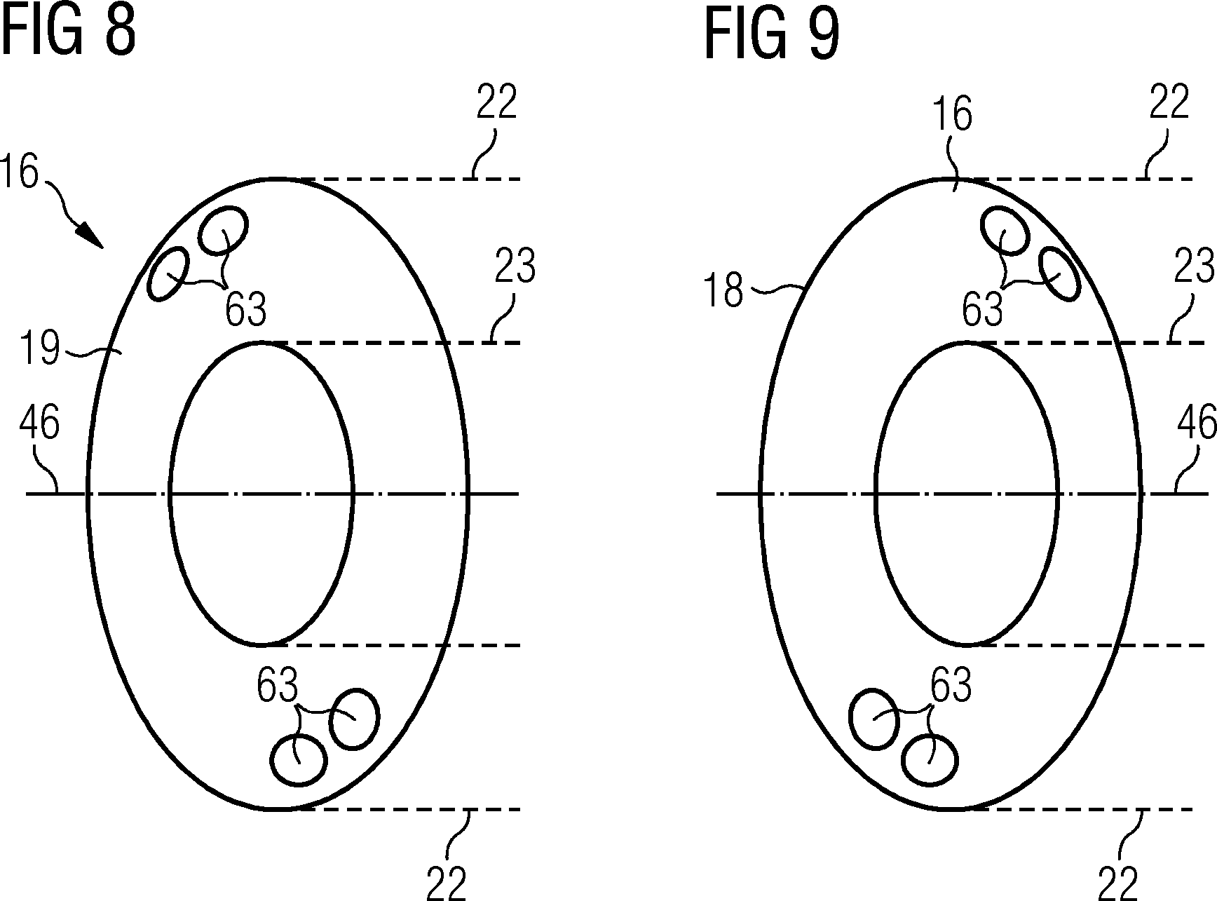

FIG 11

5/5
FIG 12


FIG 14


Electromagnet Assembly
The present disclosure relates to an electromagnetic assembly.
In particular the disclosure relates to an electromagnet assembly for a superconducting magnet.
Background
Superconducting magnet structures may comprise an outer shield coil which bounds a main coil assembly, with structural restraints provided between the outer shield coil and the main coil assembly. This sub assembly may be contained within a housing which, in operation, contains an inert gas as a coolant, for example helium. Hence the housing forms a cryogen vessel, which enables the coil assemblies to be cooled to sufficiently low temperatures to optimise their performance.
The superconducting magnet structures, which are of a precise design and manufactured to within small tolerances, can be subject to significant shock and vibration loads during transport. These loads can cause damage, for example distorting the relative positions of the outer coil and main coil assembly with deleterious effects on their performance during operation.
The material properties of the magnet structure and the cryogen vessel may be significantly different, leading to significantly different rates and extent of thermal contraction and expansion between the coil assemblies and the surrounding housing. This limits the ability to mount the magnet coil assemblies at multiple locations, as doing so would over constrain thermal movement leading to stresses being induced in the assembly, which may lead to distortion, with a consequential loss of performance.
Hence the tendency is to reinforce the structural restraints between the outer shield coil and the main coil assembly. This can result in complex and over engineered solutions which are not required during the operation of the superconducting magnet, and may, because of their mass and geometry, be deleterious to the performance of the superconducting magnet.
Hence a superconducting magnet with a structure which limits the effect of transport loads on the magnet assembly, but is of minimalist design to minimise overall weight of the structure, as well as not interfering with the operation of the magnet, is highly desirable.
Summary
According to the present disclosure there is provided an apparatus as set forth in the appended claims. Other features of the invention will be apparent from the dependent claims, and the description which follows.
Accordingly there may be provided an electromagnet assembly comprising : an outer shield coil assembly having a first end and a second end; a housing comprising : a first end wall and a second end wall spaced apart from one another by a side wall; the outer shield coil assembly and housing being centred on a common assembly axis; and the electromagnet assembly further comprising : a first support pin which extends between and couples the first end wall of the housing and the first end of the outer shield coil assembly a second support pin which extends between and couples, the second end wall of the housing and the second end of the outer shield coil assembly; such that the outer shield coil assembly is carried by the housing, and the coupling of the end walls of the housing and ends of the outer shield coil assembly is configured to prevent relative radial and rotational movement between the outer shield coil assembly and the housing.
The coupling between the outer shield coil assembly and the end walls of the housing may be configured to allow relative axial movement between the outer shield coil assembly and the housing at the first end and second end of the outer shield coil assembly.
Both the first pin and second pin may be provided with a fixing means configured such that the outer shield coil assembly and the end walls of the housing are fixed relative to one another to prevent relative axial movement between the outer shield coil assembly and the housing.
The coupling between the first end of the outer shield coil assembly and the first end wall of the housing may be configured to allow relative axial movement between the first end of the outer shield coil assembly and the housing at the first end of the outer shield coil assembly; and the second pin may be provided with a fixing means configured such that the second end of the outer shield coil assembly and the second end wall of the housing are fixed relative to one another to restrict relative axial movement between the outer shield coil assembly and the housing at the second end of the electromagnet assembly.
The first and second pin may extend from, and be fixed to, the first and second end walls of the housing respectively, and each of the first and second pins may terminate in a free end spaced apart from their respective end wall.
The first end of the outer shield coil assembly may be provided with a first end mounting feature for receiving the first pin; and the second end of the outer shield coil assembly may be provided with a second end mounting feature for receiving the second pin.
The first and second end mounting features may each comprise a support mount which extends from their respective ends of the outer shield coil assembly wherein the support mount of each of the first and second end mounting features is provided with an aperture configured to receive the first and second support pins respectively.
The first and second pin may extend from, and may be fixed to, the first and second ends of the outer shield coil assembly respectively, and each of the first and second pins may terminate in a free end spaced apart from their respective end of the outer shield coil assembly.
The first end wall of the housing may be provided with a first end mounting feature for receiving the first pin; and the second end wall of the housing may be provided with a second end mounting feature for receiving the second pin.
The first and second end mounting feature may comprise a support mount which extends from their respective end walls of the housing wherein the support mount of each of the first and second end mounting features is provided with an aperture configured to receive the first and second support pins respectively.
A biasing member may be provided between at least one of the housing end walls and the outer shield coil assembly to bias the outer shield coil assembly away from the at least one housing end wall.
There may be provided a plurality of first pins for engagement with a corresponding number of first end mounting features; and there are also provided a plurality of second pins for engagement with a corresponding number of second end mounting features.
There may be provided a plurality of first pins spaced around the first end wall of the housing for engagement with a corresponding number of first end mounting features provided on the first end of the outer shield coil assembly; and there may also be provided a plurality of second pins spaced around the second end wall of the housing for engagement with a corresponding number of second end mounting features provided on the second end of the outer shield coil assembly.
There may be provided a plurality of first pins spaced around the first end of the outer shield coil assembly for engagement with a corresponding number of first end mounting features provided on the first end wall of the housing; and there may also be provided a plurality of second pins spaced around the second end of the outer shield coil assembly for engagement with a corresponding number of second end mounting features provided on the second end wall of the housing.
The electromagnet assembly may further comprise a main coil assembly bounded by the outer shield coil assembly.
The electromagnet assembly may further comprise an inner side wall which extends between the first end wall and a second end wall such that the housing end walls, outer wall and inner wall define a chamber which houses the main coil assembly and the outer shield coil assembly.
The main coil assembly may be mounted on the inner side wall such that the main coil assembly is prevented from moving radially relative to the inner side wall.
Structural restraints may be provided between the outer shield coil assembly and the main coil assembly, to thereby hold the main coil assembly in a substantially fixed position relative to the outer shield coil assembly.
The outer shield coil assembly may comprise a shield coil which extends between the first end and second end of the outer shield coil assembly.
Hence there is provided an electromagnet assembly in which components of the electromagnet are supported at both ends of the assembly structure in such a way to minimise the effect of loads induced on the assembly during transport, as well as assisting in maintaining the relative positions of the elements of the electromagnet assembly during operation.
Brief Description of the Drawings
Examples of the present disclosure will now be described with reference to the accompanying drawings, in which:
Figure 1 shows a perspective view of part of an electromagnet assembly of the present disclosure;
Figure 2 is an end view of the assembly shown in Figure 1;
Figure 3 is a cross-sectional view of the electromagnet assembly shown in Figure 1;
Figure 4 shows a view of a region of an end of an outer shield coil assembly of the present disclosure;
Figure 5 shows an enlarged view of the ends of the electromagnet assembly shown in Figure 3;
Figures 6, 7 show views of alternative examples of ends of the electromagnet assembly of the present disclosure;
Figures 8, 9 show a partially exploded view of end walls on which support pins of the electromagnet assembly of the present disclosure are mounted;
Figure 10 shows a view of a support pin according to the present disclosure;
Figure 11 shows another example of a support pin according to the present disclosure;
Figure 12 shows an example of a biasing member included in an example of the electromagnet assembly of the present disclosure;
Figure 13 shows a cross-sectional view of an alternative example of an electromagnet assembly according to the present disclosure; and
Figure 14 shows an alternative example of an outer shield coil assembly according to the present disclosure.
Detailed Description
Figure 1 shows a side view of part of an electromagnet assembly 10 of the present disclosure. Figure 2 shows an end view of the assembly 10 shown in Figure 1. The electromagnet assembly 10 may comprise part of a superconducting magnet. In particular the electromagnet assembly 10 may comprise part of a superconducting magnet for a Magnetic Resonance Imaging machine (MRI).
As shown in Figures 1, 2 the electromagnet assembly 10 comprises an outer shield coil assembly 12 which bounds (i.e. surrounds) a main coil assembly 14.
As shown partially in Figures 3, 8 and 9, the electromagnetic assembly further comprises a housing 16. The housing 16 comprises a first end wall 18 and a second end wall 19 opposite the first end wall 18 spaced apart from one another by an outer side wall 22 which bounds the outer shield coil assembly 12. The outer side wall 22 is cylindrical and extends around the entire circumference of the outer shield coil assembly 12. Additionally there is provided an inner side wall 23 (or “bore tube”) which extends between the first end wall 18 and a second end wall 19. The bore tube 23 is cylindrical and extends around, and may be in contact with, an entire inner circumference of the main coil assembly 14. The main coil assembly 14 is thus carried and supported by, and coupled to, the bore tube 23 such that the main coil assembly 14 is slideable relative to the bore tube 23, but is prevented from moving radially relative to the bore tube 23. Put another way, the main coil assembly 14 may be mounted on the inner side wall 23 such that the main coil assembly 14 is prevented from moving radially relative to the inner side wall 23.
Hence the housing 16 comprises the end walls 18, 19, outer wall 22 and inner wall 23, and thus defines and provides a chamber 20 which houses the main coil assembly 14 and the outer shield coil assembly 12. In use the chamber 20 may optionally be filled with a coolant, for example helium, to optimise the performance of the main coil assembly 14 and shield coil assembly 12. Whether or not coolant is provided will, of course, depend on the specification of the electromagnetic assembly.
In the example shown the outer shield coil assembly 12 comprises two shield coils 24, each mounted in a respective journal 26, the journals 26 being connected to main coil assembly 14, spaced apart from one another, by a cage framework 28. In an alternative example, shown in Figure 13, the outer shield coil assembly 12 comprises a single shield coil 24 which extends between the first end 30 and second end 34 of the outer shield coil assembly 12. In a further alternative example the outer shield coil assembly may comprise more than two outer shield coils 26. In such an example the outer shield coil may be mounted on a cage/frame akin to that shown in Figure 1.
The outer shield coil assembly 12 has a first end 30 provided with a first end mounting feature 32 and a second end 34 opposite the first end 30 provided with a second end mounting feature 36.
As shown in Figure 3, the main coil assembly 14 has a first end 31 and second end 35.
In the example shown both the outer shield coil assembly 12 and main coil assembly 14 are substantially cylindrical.
Structural restraints 42 are provided between the outer shield coil assembly 12 and the main coil assembly 14 to thereby hold the main coil assembly 14 in a substantially fixed position relative to the outer shield coil assembly 12.
In the example shown in Figure 1, the structural restraints 42 extend radially inwards (with respect to the assembly axis 46) from the cage 28 of the outer coil assembly 12 to the main coil assembly 14.
In an alternative example, as shown in Figure 13, the structural restraints 42 may instead extend radially inwards (with respect to the assembly axis 46) from the journal 26 of the outer coil assembly 12 to the main coil assembly 14.
The outer shield coil assembly 12 and main coil assembly 14 are concentrically and coaxially aligned and centred on (i.e. co-axial with) an assembly axis 46. The assembly axis 46 extends along the longitudinal length of the assembly 10, between the first end 30 and second end 34 of the outer shield coil assembly 12, and between the first end wall 18 and second end wall 19 of the housing 16.
The structural restraints 42 are required to provide precise positioning of the shield coils 24 relative to the main coil assembly 14, and to provide support of electromagnetic loads, especially in directions in which the housing 16 is not sufficiently stiff. The structural restraints 42 thus provide rotational and axial support of the main coil assembly 14 from the outer shield coil assembly 12.
The structural restraints 42 extend between elements of the cage frame 28 which spaces apart the shield coils 24 and the main coil assembly 14. The structural restraints 42 are spaced around the circumferences of the outer and main coil assemblies 12, 14, as shown in Figure 2.
The first end wall 18 of the housing 16 is located proximate to the first end 30 of the outer shield coil assembly 12 and second end wall 19 of the housing is located proximate to the second end 34 of the outer shield coil assembly 12.
As shown in Figures 2 to 7, the first and second end mounting features 32, 36 each comprise a support mount 50 (e.g. wall) which extends from the end of their respective ends 30, 34 of the outer shield coil assembly 12. The support mount 50 may be provided as a flange 52, as shown in Figures 2 to 7, 14 or as a plate 54 supported from the main body of the outer shield coil assembly 12, or as a boss 51 as shown in Figure 14. Alternatively the mounting feature 32, 36 may be provided in any other suitable form, for example an aperture or bearing surface provided in or on a side wall of the coil journals 26.
A first support pin 60 (or “dowel”) extends between and couples the first end wall 18 of the housing 16 and the first end 30 of the outer shield coil assembly 12. That is to say, with reference to the examples shown in Figures 5 to 7 and Figure 13, the first support pin 60 (or “dowel”) extends between, and engages with, the first end wall 18 of the housing 16 and the first end mounting feature 32 of the outer shield coil assembly 12 to thereby support the outer shield coil assembly 12 on the housing 16.
A second support pin 62 extends between and couples, the second end wall 19 of the housing 16 and the second end 34 of the outer shield coil assembly 12. That is to say, with reference to the examples shown in the figures, the second support pin 62 (or “dowel”) extends between, and engages with, the second end wall 19 of the housing 16 and the second end mounting feature 36 of the outer shield coil assembly 12, to thereby support the outer shield coil assembly 12 on the housing 16.
In the examples of Figures 5 to 7 and Figure 13 each of the first and second pins terminate in a free end spaced apart from their respective end wall 18, 19. The first pin 60 extends from the first end wall 18 in a first direction, and the second pin 62 extends from the second end wall 19 in a second direction opposite to the first direction. That is to say, the first pin 60 extends from the first end wall 18 of the housing 16 towards the second end wall 19 of the housing 16, and the second pin 62 extends from the second end wall 19 of the housing 16 towards the first end wall 18 of the housing 16.
The support mount (or wall) 50 of each of the first and second end mounting features 32, 36 is provided with an aperture 56, 58 configured to receive the first and second support pins 60, 62 respectively.
At least one of the first pin 60 and first end mounting feature 32, and second pin 62 and second end mounting feature 36, may be engaged (i.e. co-operatively mounted) to permit relative axial movement between the outer shield coil assembly and the housing along the assembly axis 46.
Both of the first pin 60 and first end mounting feature 32, and second pin 62 and second end mounting feature 36 are co-operatively mounted to inhibit (i.e. prevent) relative radial and/or rotational movement between the outer shield coil assembly 12 and the housing 16 relative to (i.e. around) the assembly axis 46.
The first pin 60 and/or second pin 62 are rigidly fixed relative to their respective end walls 18, 19 of the housing 16. The first pin 60 and/or second pin 62 may be welded, riveted or fixed in some other suitable way to their respective end walls 18, 19 of the housing 16.
There may be provided a plurality of first pins 60 in a series spaced around the first end wall 18 of the housing 16 for engagement with a corresponding number of first end mounting features 32 provided on the first end 30 of the outer shield coil assembly 12. There may also be provided a plurality of second pins 62 in a series spaced around the second end wall 19 of the housing 16 for engagement with a corresponding number of second end mounting features 36 provided on the second end 34 of the outer shield coil assembly 12. Hence hereafter, although first pin 60 and second pin 62 may be referred to, in each example there may alternatively be provided a plurality of first and/or second pins 60, 62.
The series of first pins 60 and second pins 62 may be equally spaced around the ends of the outer shield coil assembly 12. Alternatively the series of first pins 60 and second pins 62 may be spaced apart by different distances around the ends of the outer shield coil assembly 12. The series of first pins 60 may be located on a common pitch circle diameter (PCD). The second pins 62 may be located on a common pitch circle diameter (PCD).
Figures 8, 9 show alternative example locations 63 of the support pins on the end walls 18, 19 of the housing 16. In this example only pairs of first and second pins 60, 62 may be provided on each of the end walls 18, 19, one pair of pins 60, 62 being located adjacent to one another, another pairs of pins 60, 62 being diametrically opposite (that is to say, the two pairs of pins are spaced 180 degrees apart), such that the two pairs of pins are spaced apart from one another around the circumference of the end wall of the housing 16.
There may be provided an equal number of first pins 60 and second pins 62. Alternatively more first pins 60 may be provided than second pins 62, or fewer first pins 60 may be provided than second pins 62.
As shown in the example of Figures 3, 5 (where Figure 5 shows an enlarged view of the ends of the assembly 10), the first pin 60 and its respective mounting feature 32 are configured (for example sized relative to one another) to allow relative axial movement between the first pin 60 and its respective mounting feature 32 at the first end 30 of the outer shield coil assembly 12 along the assembly axis 46. Put another way, the coupling between the first end of the outer shield coil assembly 12 and the first end walls of the housing by the first pin is configured to allow relative axial movement between the first end of the outer shield coil assembly 12 and the housing at the first end of the outer shield coil assembly. That is to say, there may be provided a clearance between the first pin 60 and the aperture 56 of the mounting feature 32 to provide a loose fit so the pin 60 and bearing surface of the mounting feature 32 may move relative to one another (for example slide relative to one another). This permits relative axial movement between the housing 16 and the outer shield coil assembly 12 at the first end of the outer shield coil assembly 12 along the assembly axis 46 but also inhibits (i.e. prevents) relative radial and/or rotational movement between the outer shield coil assembly 12 and the housing 16 relative to the assembly axis 46 since the pin 60 cannot move relative to the mounting feature 32 in a radial direction (with respect to the assembly axis 46) or move relative to the mounting feature 32 in a circumferential direction around the assembly axis 46.
As shown in Figure 11, the first pin 60 may extend from a boss 70 on the end wall 18. A first region 72 extends from the boss 70 and has a first diameter. It may also have a second region 74 which extends from the first region, which tapers to a smaller diameter to provide a lead-in feature. Hence the first pin 60 is configured to provide a loose fit pin feature with an alignment lead-in feature, with the first region 72 providing a bearing surface when the first pin 60 is in position within the aperture 56 of the mounting feature 32. The first pin 60 may be plane/smooth sided.
Thus at the first end 30 the outer shield coil assembly 12 is partially constrained relative to the first end wall 18. The first pin 60 supports the outer shield coil assembly 12 in critical load cases. However, the configuration allows for relative axial movement of the housing 16 and the outer shield coil assembly 12 to relieve any forces due to thermal expansion and contraction and build tolerances.
As shown in Figure 10, the second pin 62 of the example of Figures 3, 5 may extend from a boss 90 on the end wall 18. A first region 92 extends from the boss 90 and has a first diameter. It may also have a second region 94 which extends from the first region, with a second diameter, less than the first diameter. As shown in Figure 8, there may be provided a tampered/chamfered transition region 96 between the first region 92 and second region 94. Hence the second region provides a loose fit pin feature with an alignment shoulder provided by the transition region 96, with the first region providing a bearing surface when the second pin 62 is in position within the mounting feature 36. The second region 94 may be provided with a male threaded feature 98 so that a threaded fastener 100 may be provided on the second region 94 to fix the wall (or plate) which defines the mounting feature to the second pin 62 (as shown in Figures 3, 5). Alternatively a clip or other suitable fixing may be provided instead of a threaded fastener.
Thus as shown in the example of Figures 3, 5 the second pin 62 is provided with a fixing means 80 (for example a threaded fastener 100) to fix the second pin 62 to its respective mounting feature 36 at the second end 34 of the outer shield coil assembly 12. This inhibits relative axial movement between the housing 16 and the outer shield coil assembly 12 at the second end 34 of the outer shield coil assembly 12. Put another way, the second pin is provided with a fixing means 80 configured such that the coupling between the second end 34 of the outer shield coil assembly 12 and the second end wall of the housing by the second pin fixes the second end 34 of the outer shield coil assembly 12 and the second end wall of the housing relative to one another to prevent relative axial movement between the outer shield coil assembly 12 and the housing at the second end of the electromagnet assembly. Additionally the mounting of the second pin 62 in the aperture 58 also inhibits (i.e. prevents) relative radial and/or rotational movement between the outer shield coil assembly 12 and the housing 16 relative to the assembly axis 46 since the pin 62 cannot move relative to the mounting feature 36 in a radial direction (with respect to the assembly axis 46) or move relative to the mounting feature 36 in a circumferential direction around the assembly axis 46.
As shown in Figures 3, 5, 6, a spacer 102 may be provided between the wall/plate which defines the mounting feature 36 and the base (i.e. boss) of the second pin 62. A spacer (for example a washer) 102 may also be provided between the threaded fastener 100 and the wall/plate which defines the mounting feature 36 in the “inner” surface of the second end of the outer coil assembly 12.
The fixing means 80 ensures the outer shield coil assembly 12 is fully constrained to the second end wall 19 of the housing 16, although clearances allow for differential thermal contraction and build tolerances.
Thus in the example of Figures 3, 5 the first pin and second pin are of substantially different design, the first pin allowing relative axial movement and the second pin configured to prevent relative axial movement.
In a further example, as shown in Figure 6, the first pin and second pin 60, 62 are both provided with a fixing means 80 to fix the pin 60, 62 to the respective mounting feature 32, 36. The fixing means 80 inhibits relative axial movement between the housing 16 and the outer shield coil assembly 12. Put another way, both the first pin and second pin are provided with a fixing means 80 configured such that the coupling between the outer shield coil assembly 12 and the end walls of the housing by the first and second pins fix the outer shield coil assembly 12 and the end walls of the housing relative to one another to prevent relative axial movement between the outer shield coil assembly 12 and the housing at both ends of the outer shield coil assembly 12. Thus in this example, the first and second pin(s) are of substantially the same design, having the same design as the second pins 62 of the example shown in Figures 3, 5.
In this example, the coil assemblies may be constructed from materials having similar coefficient of thermal expansion to limit differences in thermal expansion and contraction during use. Alternatively or additionally, flexibility or additional clearances may be provided in the design to limit the effects of different rates and extent of thermal expansion and contraction of the housing and coil assemblies.
In an alternative example, for example as shown in Figure 7, the first pin 60 and second pin 60 and their respective mounting feature 32, 36 are configured (that is to say, sized relative to one another) to allow relative axial movement between the pins 60, 60 and their respective mounting feature 32, 36. In this example, this allows relative axial movement between the housing 16 and the outer shield coil assembly 12 along the assembly axis 46. Put another way, the coupling between the outer shield coil assembly 12 and the end walls of the housing by the first and second pins is configured to allow relative axial movement between the outer shield coil assembly 12 and the housing at the first end 30 and second end 34 of the outer shield coil assembly 12. Thus in this example, the first and second pin(s) and mounting features are of substantially the same design, having the same design as the first pins 60 of the example shown in Figures 3, 5.
In the example of Figure 7, and as illustrated in Figure 12, a biasing member 110 may be provided between at least one of the housing end walls 18, 19 and the outer shield coil assembly 12 to bias the outer shield coil assembly 12 axially away from the housing end walls 18, 19. In particular, a first biasing member 110 may be provided between the housing first end wall 18 and the outer shield coil assembly 12 and a second biasing member 110 may be provided the housing second end wall 19 and the shield coil assembly 12.
The biasing member 110 may be provided as a spring. A biasing member 110 may be introduced at one or both ends of the housing such that the biasing member(s) are operable to assist with providing support due to differential thermal contraction between the material of the housing 16 and the coil assemblies 12, 14, and may also provide vibration damping.
Alternatively, or additionally in the Figure 7 example, the outer coil assembly 12 may be held in place between the end walls of the housing by the pins 60, 62 by compression introduced during the build process, either by tooling or weld shrinkage to a predetermined amount.
Thus, in operation, the coupling of the end walls 18, 19 of the housing 16 to the ends of the outer shield coil assembly 12 inhibits relative radial and rotational movement between the outer shield coil assembly 12 and the housing 16 around the assembly axis 46.
Additionally, coupling of the end walls 18, 19 of the housing 16 and ends of the outer shield coil assembly 12 in combination with the coupling of the main coil assembly 14 and the bore tube 23 also prevents relative radial movement between the outer shield coil assembly 12 and the main coil assembly 14.
Different degrees of relative axial movement between the outer shield coil assembly 12 and the housing 16 along the assembly axis 46 are provided by the different examples described above.
The invention of the present disclosure is applicable to other electromagnetic assembly designs. For example whereas in Figure 1 an outer shield coil assembly 12 is shown with a cage support structure 28 carrying the journals of the coil assemblies, with the mounting features extending from the journals, it may equally be applied to electromagnetic assembly designs having a different structure.
As referred to above, and as shown in Figure 13, in an alternative example the outer shield coil assembly 12 may comprises a single shield coil 24 which extends between the first end 30 and second end 34 of the outer shield coil assembly 12. Additionally, the outer shield coil assembly 12 may be significantly shorter than the main coil assembly 14. Further the structural restraints 42 may extend radially inwards from the journal 26 of the outer coil assembly 12 to the main coil assembly 14. The housing end walls 18, 19 may thus be formed with angled sections to accommodate the smaller outer shield coil assembly, and the bosses 70, 90 of the support pins 60, 62 may be extended relative to previous examples to provide the necessary support.
Although in the preceding examples shown in the figures the pins, or dowels, extend from the end wall of the housing to be received in mounting features of the outer shield coil assembly, in alternative examples (for example as shown in Figure 14) the pins or dowels may extend from the outer shield coil assembly to be received in mounting features (for example apertures provided in the housing, or apertures provided in bosses or flanges which extend from the housing, as shown in Figure 14) provided in/on the end walls of the housing.
Hence the first and second pin 60, 62 may extend from, and be fixed to, the first and second ends 30, 34 of the outer shield coil assembly 12 respectively, and each of the first and second pins 60, 62 may terminate in a free end spaced apart from their respective end 30, 34 of the outer shield coil assembly. The first end wall 18 of the housing may be provided with a first end mounting feature 32 for receiving the first pin 60, and the second end wall 19 of the housing 16 may be provided with a second end mounting feature 36 for receiving the second pin 62. The first and second end mounting feature 32, 36 may comprise a support mount 50 (which may be provided as a wall, boss or plate) which extends from their respective end walls 18, 19 of the housing 16, wherein the support mount 50 of each of the first and second end mounting features 32, 36 may be provided with an aperture 56, 58 configured to receive the first and second support pins 60 respectively. Alternatively the mounting feature 32, 36 may be provided in any other suitable form, for example an aperture or bearing surface provided in or on a side wall of the coil journals 26.
There is thus provided an arrangement which provides additional support to an electromagnet structure, which may be a superconducting magnet, during transit. Critically it ensures electromagnet shield coils are supported from each end wall of the housing which surrounds them. This limits deflection, hence stresses, under load cases experienced during the magnet’s lifetime.
The arrangements of the present disclosure uses otherwise redundant vessel housing structure to provide structural support to the magnetic coils. The provision of support pins in the way described above hence also reduces the loading requirement on support structure struts between the outer shield coils and inner coils, thus enabling partial removal/reduction of support features, for example support struts 42 and/or elements of the cage 28 (in examples where present). This reduces the amount of material required to define the structure, resulting in a lighter assembly.
The additional support provided by the pins 60, 62 permits a magnet support structure with lower stiffness which can absorb differential thermal contraction between inner and outer structure. It also limits deflection of shield coils relative to the inner magnet for critical shock load cases.
Thus the support structure of the electromagnet assembly of the present disclosure balances requirement for load bearing with flexibility to accommodate differential thermal contraction between the coil assemblies and the housing which surrounds them.
Attention is directed to all papers and documents which are filed concurrently with or previous to this specification in connection with this application and which are open to public inspection with this specification, and the contents of all such papers and documents are incorporated herein by reference.
All of the features disclosed in this specification (including any accompanying claims, abstract and drawings), and/or all of the steps of any method or process so disclosed, may be combined in any combination, except combinations where at least some of such features and/or steps are mutually exclusive.
Each feature disclosed in this specification (including any accompanying claims, abstract and drawings) may be replaced by alternative features serving the same, equivalent or similar purpose, unless expressly stated otherwise. Thus, unless expressly stated otherwise, each feature disclosed is one example only of a generic series of equivalent or similar features.
The invention is not restricted to the details of the foregoing embodiment(s). The invention extends to any novel one, or any novel combination, of the features disclosed in this specification (including any accompanying claims, abstract and drawings), or to any novel one, or any novel combination, of the steps of any method or process so disclosed.
Claims (15)
1 An electromagnet assembly (10) comprising :
an outer shield coil assembly (12) having a first end (30); and a second end (34);
a housing (16) comprising :
a first end wall (18) and a second end wall (19) spaced apart from one another by a side wall (22);
the outer shield coil assembly (12) and housing (16) being centred on a common assembly axis (46);
and the electromagnet assembly (10) further comprising :
a first support pin (60) which extends between and couples the first end wall (18) of the housing (16) and the first end (30) of the outer shield coil assembly (12) a second support pin (62) which extends between and couples, the second end wall (18) of the housing (16) and the second end (34) of the outer shield coil assembly (12);
such that the outer shield coil assembly (12) is carried by the housing (16), and the coupling of the end walls (18, 19) of the housing (16) and ends of the outer shield coil assembly (12) is configured to prevent relative radial and rotational movement between the outer shield coil assembly (12) and the housing (16).
2 An electromagnet assembly (10) as claimed in claim 1 wherein the coupling between the outer shield coil assembly (12) and the end walls (18,19) of the housing (16) is configured to allow relative axial movement between the outer shield coil assembly (12) and the housing (16) at the first end (30) and second end (34) of the outer shield coil assembly (12).
3 An electromagnet assembly (10) as claimed in claim 1 wherein both the first pin (60) and second pin (62) are provided with a fixing means (80) configured such that the outer shield coil assembly (12) and the end walls (18,19) of the housing (16) are fixed relative to one another to prevent relative axial movement between the outer shield coil assembly (12) and the housing (16).
4 An electromagnet assembly (10) as claimed in claim 1 wherein the coupling between the first end (30) of the outer shield coil assembly (12) and the first end wall (18) of the housing (16) is configured to allow relative axial movement between the first end (30) of the outer shield coil assembly (12) and the housing (16) at the first end (30) of the outer shield coil assembly (12); and the second pin (62) is provided with a fixing means (80) configured such that the second end (34) of the outer shield coil assembly (12) and the second end wall (19) of the housing (16) are fixed relative to one another to restrict relative axial movement between the outer shield coil assembly (12) and the housing (16) at the second end of the electromagnet assembly (10).
5 An electromagnet assembly (10) as claimed in any one of claims 1 to 4 wherein the first and second pin (60, 62) extend from, and are fixed to, the first and second end walls (18, 19) ofthe housing (16) respectively, and each ofthe first and second pins (60, 62) terminate in a free end spaced apart from their respective end wall (18, 19).
6 An electromagnet assembly (10) as claimed in any one of claims 1 to 5 wherein the first end (30) of the outer shield coil assembly (12) is provided with a first end mounting feature (32) for receiving the first pin (60); and the second end (34) ofthe outer shield coil assembly (12) is provided with a second end mounting feature (36) for receiving the second pin (62).
7 An electromagnet assembly (10) as claimed in any one of claims 1 to 4 wherein the first and second pin (60, 62) extend from, and are fixed to, the first (30) and second (34) ends ofthe outer shield coil assembly (12) respectively, and each ofthe first and second pins (60, 62) terminate in a free end spaced apart from their respective end ofthe outer shield coil assembly (12).
8 An electromagnet assembly (10) as claimed in any one of claims 1 to 6 wherein the first end wall (18) ofthe housing (16) is provided with a first end mounting feature (32) for receiving the first pin (60); and the second end wall (19) ofthe housing (16) is provided with a second end mounting feature (36) for receiving the second pin (62).
9 An electromagnet assembly (10) as claimed in any one of the preceding claims wherein a biasing member (110) is provided between at least one ofthe housing end walls (18, 19) and the outer shield coil assembly (12) to bias the outer shield coil assembly (12) away from the at least one housing end wall (18, 19).
10 An electromagnet assembly (10) as claimed in any one of claims 7 to 11 wherein there are provided a plurality of first pins (60) for engagement with a corresponding number of first end mounting features (32); and there are also provided a plurality of second pins (62) for engagement with a corresponding number of second end mounting features (36).
11 An electromagnet assembly (10) as claimed in any one of the preceding claims further comprising :
a main coil assembly (14) bounded by the outer shield coil assembly (12).
12 An electromagnet assembly (10) as claimed in claim 11 further comprising :
an inner side wall (23) which extends between the first end wall (18) and a second end wall (19);
such that the housing end walls (18, 19), outer wall (22) and inner wall (23) define a chamber (20) which houses the main coil assembly (14) and the outer shield coil assembly (12).
13 An electromagnet assembly (10) as claimed in claim 12 wherein :
the main coil assembly (14) is mounted on the inner side wall (23) such that the main coil assembly (14) is prevented from moving radially relative to the inner side wall (23).
14 An electromagnet assembly (10) as claimed in any one of claims 11 to 13 wherein structural restraints (42) are provided between the outer shield coil assembly (12) and the main coil assembly (12), to thereby hold the main coil (12) assembly in a substantially fixed position relative to the outer shield coil assembly (12).
15 An electromagnet assembly (10) as claimed in any one of the preceding claims wherein the outer shield coil assembly (12) comprises a shield coil (24) which extends between the first end (30) and second end (34) of the outer shield coil assembly (12).
Intellectual
Property
Office
Application No: Claims searched:
Priority Applications (2)
| Application Number | Priority Date | Filing Date | Title |
|---|---|---|---|
| US15/934,198 US10878983B2 (en) | 2017-03-24 | 2018-03-23 | Electromagnetic assembly |
| CN201810254496.3A CN108630375B (en) | 2017-03-24 | 2018-03-26 | Electromagnet assembly |
Applications Claiming Priority (1)
| Application Number | Priority Date | Filing Date | Title |
|---|---|---|---|
| GBGB1704683.0A GB201704683D0 (en) | 2017-03-24 | 2017-03-24 | Electromagnetic assembley |
Publications (3)
| Publication Number | Publication Date |
|---|---|
| GB201710640D0 GB201710640D0 (en) | 2017-08-16 |
| GB2560777A true GB2560777A (en) | 2018-09-26 |
| GB2560777B GB2560777B (en) | 2020-06-03 |
Family
ID=58687946
Family Applications (2)
| Application Number | Title | Priority Date | Filing Date |
|---|---|---|---|
| GBGB1704683.0A Ceased GB201704683D0 (en) | 2017-03-24 | 2017-03-24 | Electromagnetic assembley |
| GB1710640.2A Active GB2560777B (en) | 2017-03-24 | 2017-07-03 | Electromagnet assembly |
Family Applications Before (1)
| Application Number | Title | Priority Date | Filing Date |
|---|---|---|---|
| GBGB1704683.0A Ceased GB201704683D0 (en) | 2017-03-24 | 2017-03-24 | Electromagnetic assembley |
Country Status (3)
| Country | Link |
|---|---|
| US (1) | US10878983B2 (en) |
| CN (1) | CN108630375B (en) |
| GB (2) | GB201704683D0 (en) |
Families Citing this family (2)
| Publication number | Priority date | Publication date | Assignee | Title |
|---|---|---|---|---|
| DE102015201373A1 (en) * | 2015-01-27 | 2016-07-28 | Siemens Aktiengesellschaft | Superconducting magnet arrangement, in particular for a magnetic resonance tomograph |
| DE102020209840A1 (en) * | 2020-08-05 | 2022-02-10 | Robert Bosch Gesellschaft mit beschränkter Haftung | Method for manufacturing a camera module, camera module |
Citations (5)
| Publication number | Priority date | Publication date | Assignee | Title |
|---|---|---|---|---|
| US6570475B1 (en) * | 2000-11-20 | 2003-05-27 | Intermagnetics General Corp. | Split type magnetic resonance imaging magnet |
| JP2007053241A (en) * | 2005-08-18 | 2007-03-01 | Kobe Steel Ltd | Superconducting magnet device |
| WO2011122403A1 (en) * | 2010-03-30 | 2011-10-06 | ジャパンスーパーコンダクタテクノロジー株式会社 | Superconducting magnet device |
| US20130157865A1 (en) * | 2011-12-20 | 2013-06-20 | General Electric Company | System for magnetic field distortion compensation and method of making same |
| WO2016066526A1 (en) * | 2014-10-27 | 2016-05-06 | Siemens Plc | Support of superconducting coils for mri systems |
Family Cites Families (16)
| Publication number | Priority date | Publication date | Assignee | Title |
|---|---|---|---|---|
| US4344056A (en) * | 1980-07-31 | 1982-08-10 | Warner Electric Brake & Clutch Company | Electromagnet with replaceable friction face |
| US5138326A (en) * | 1988-10-14 | 1992-08-11 | Oxford Medical Limited | Magnetic field generating assembly and method |
| JPH04328477A (en) * | 1991-04-30 | 1992-11-17 | Mitsubishi Electric Corp | Electromagnet device |
| US5247800A (en) * | 1992-06-03 | 1993-09-28 | General Electric Company | Thermal connector with an embossed contact for a cryogenic apparatus |
| GB2307045B (en) * | 1995-11-08 | 2000-06-14 | Oxford Magnet Tech | Improvements in or relating to super-conducting nagnets |
| DE19622634A1 (en) * | 1996-06-05 | 1997-12-11 | Nass Magnet Gmbh | Solenoid coil and process for its manufacture |
| JP2001317564A (en) * | 2000-02-29 | 2001-11-16 | Sanden Corp | Electromagnetic clutch yoke |
| JP2001241468A (en) * | 2000-02-29 | 2001-09-07 | Sanden Corp | Yoke for electromagnetic clutch |
| KR100780148B1 (en) * | 2002-09-26 | 2007-11-27 | 세이코 엡슨 가부시키가이샤 | Drive mechanism |
| CA2503935A1 (en) * | 2004-04-08 | 2005-10-08 | Polymer Technologies Inc. | Electromagnetic coil assembly |
| JP4749699B2 (en) | 2004-11-17 | 2011-08-17 | 株式会社日立メディコ | Magnetic resonance imaging system |
| US20060226940A1 (en) * | 2005-04-07 | 2006-10-12 | Hitachi Global Storage Technologies | Method and apparatus for setting a sensor AFM with a superconducting magnet |
| CN103901371B (en) | 2012-12-24 | 2017-04-19 | 通用电气公司 | System for magnetic field distortion compensation and method of making same |
| CN203386560U (en) | 2013-07-04 | 2014-01-08 | 上海联影医疗科技有限公司 | Superconducting magnet device |
| EP3026277B1 (en) * | 2014-11-27 | 2023-04-26 | Skf Magnetic Mechatronics | Magnetic bearing, apparatus comprising such a magnetic bearing and method for manufacturing such a magnetic bearing |
| EP3026278B1 (en) * | 2014-11-27 | 2020-03-18 | Skf Magnetic Mechatronics | Magnetic bearing, rotary apparatus comprising such a magnetic bearing and method for manufacturing such a magnetic bearing |
-
2017
- 2017-03-24 GB GBGB1704683.0A patent/GB201704683D0/en not_active Ceased
- 2017-07-03 GB GB1710640.2A patent/GB2560777B/en active Active
-
2018
- 2018-03-23 US US15/934,198 patent/US10878983B2/en active Active
- 2018-03-26 CN CN201810254496.3A patent/CN108630375B/en active Active
Patent Citations (5)
| Publication number | Priority date | Publication date | Assignee | Title |
|---|---|---|---|---|
| US6570475B1 (en) * | 2000-11-20 | 2003-05-27 | Intermagnetics General Corp. | Split type magnetic resonance imaging magnet |
| JP2007053241A (en) * | 2005-08-18 | 2007-03-01 | Kobe Steel Ltd | Superconducting magnet device |
| WO2011122403A1 (en) * | 2010-03-30 | 2011-10-06 | ジャパンスーパーコンダクタテクノロジー株式会社 | Superconducting magnet device |
| US20130157865A1 (en) * | 2011-12-20 | 2013-06-20 | General Electric Company | System for magnetic field distortion compensation and method of making same |
| WO2016066526A1 (en) * | 2014-10-27 | 2016-05-06 | Siemens Plc | Support of superconducting coils for mri systems |
Also Published As
| Publication number | Publication date |
|---|---|
| GB201710640D0 (en) | 2017-08-16 |
| US20180277291A1 (en) | 2018-09-27 |
| CN108630375B (en) | 2021-02-09 |
| CN108630375A (en) | 2018-10-09 |
| US10878983B2 (en) | 2020-12-29 |
| GB2560777B (en) | 2020-06-03 |
| GB201704683D0 (en) | 2017-05-10 |
Similar Documents
| Publication | Publication Date | Title |
|---|---|---|
| JP5534713B2 (en) | Superconducting magnet | |
| US5237300A (en) | Support structure for actively shielded superconducting magnets | |
| US5668516A (en) | Simplified active shield superconducting magnet assembly for magnetic resonance imaging | |
| US11688537B2 (en) | Electromagnet assembly | |
| US11810711B2 (en) | Cryostat assembly having a resilient, heat-conducting connection element | |
| EP1016815A2 (en) | Superconducting magnet suspension assembly | |
| US10878983B2 (en) | Electromagnetic assembly | |
| US6150912A (en) | Open architecture superconducting magnet helium vessel structure | |
| CN109979702A (en) | A kind of includes by the component of the column construction of support construction support | |
| US9711267B2 (en) | Support structure for cylindrical superconducting coil structure | |
| EP1531337A1 (en) | Superconducting magnet apparatus and magnetic resonance imaging apparatus using the same | |
| US7382134B2 (en) | Superconducting magnet apparatus for MRI | |
| US6218923B1 (en) | Magnet having shielding | |
| US6215384B1 (en) | Magnet including shielding | |
| US11193995B2 (en) | Electromagnet and assembly | |
| JP2006305146A (en) | Magnetic resonance imaging apparatus | |
| US6043729A (en) | Tube suspension assembly for superconductive magnets | |
| US11675035B2 (en) | Electromagnet and assembly | |
| CN111352053B (en) | Cryostat for superconducting magnets | |
| JP2019037429A (en) | Magnetic resonance imaging apparatus |