GB2558515A - Mountable furniture system - Google Patents
Mountable furniture system Download PDFInfo
- Publication number
- GB2558515A GB2558515A GB1607450.2A GB201607450A GB2558515A GB 2558515 A GB2558515 A GB 2558515A GB 201607450 A GB201607450 A GB 201607450A GB 2558515 A GB2558515 A GB 2558515A
- Authority
- GB
- United Kingdom
- Prior art keywords
- elements
- members
- vertical
- furniture
- cavities
- Prior art date
- Legal status (The legal status is an assumption and is not a legal conclusion. Google has not performed a legal analysis and makes no representation as to the accuracy of the status listed.)
- Withdrawn
Links
Classifications
-
- A—HUMAN NECESSITIES
- A47—FURNITURE; DOMESTIC ARTICLES OR APPLIANCES; COFFEE MILLS; SPICE MILLS; SUCTION CLEANERS IN GENERAL
- A47C—CHAIRS; SOFAS; BEDS
- A47C4/00—Foldable, collapsible or dismountable chairs
- A47C4/02—Dismountable chairs
- A47C4/021—Dismountable chairs connected by slotted joints
-
- A—HUMAN NECESSITIES
- A47—FURNITURE; DOMESTIC ARTICLES OR APPLIANCES; COFFEE MILLS; SPICE MILLS; SUCTION CLEANERS IN GENERAL
- A47B—TABLES; DESKS; OFFICE FURNITURE; CABINETS; DRAWERS; GENERAL DETAILS OF FURNITURE
- A47B3/00—Folding or stowable tables
- A47B3/06—Folding or stowable tables with separable parts
-
- A—HUMAN NECESSITIES
- A47—FURNITURE; DOMESTIC ARTICLES OR APPLIANCES; COFFEE MILLS; SPICE MILLS; SUCTION CLEANERS IN GENERAL
- A47B—TABLES; DESKS; OFFICE FURNITURE; CABINETS; DRAWERS; GENERAL DETAILS OF FURNITURE
- A47B47/00—Cabinets, racks or shelf units, characterised by features related to dismountability or building-up from elements
- A47B47/0075—Flat or flat-like panels connected without frames
-
- A—HUMAN NECESSITIES
- A47—FURNITURE; DOMESTIC ARTICLES OR APPLIANCES; COFFEE MILLS; SPICE MILLS; SUCTION CLEANERS IN GENERAL
- A47B—TABLES; DESKS; OFFICE FURNITURE; CABINETS; DRAWERS; GENERAL DETAILS OF FURNITURE
- A47B47/00—Cabinets, racks or shelf units, characterised by features related to dismountability or building-up from elements
- A47B47/0091—Modular arrangements of similar assemblies of elements
-
- A—HUMAN NECESSITIES
- A47—FURNITURE; DOMESTIC ARTICLES OR APPLIANCES; COFFEE MILLS; SPICE MILLS; SUCTION CLEANERS IN GENERAL
- A47B—TABLES; DESKS; OFFICE FURNITURE; CABINETS; DRAWERS; GENERAL DETAILS OF FURNITURE
- A47B87/00—Sectional furniture, i.e. combinations of complete furniture units, e.g. assemblies of furniture units of the same kind such as linkable cabinets, tables, racks or shelf units
- A47B87/02—Sectional furniture, i.e. combinations of complete furniture units, e.g. assemblies of furniture units of the same kind such as linkable cabinets, tables, racks or shelf units stackable ; stackable and linkable
- A47B87/0207—Stackable racks, trays or shelf units
- A47B87/0246—Shelves stackable by means of separate vertical distance-holders therebetween
-
- A—HUMAN NECESSITIES
- A47—FURNITURE; DOMESTIC ARTICLES OR APPLIANCES; COFFEE MILLS; SPICE MILLS; SUCTION CLEANERS IN GENERAL
- A47C—CHAIRS; SOFAS; BEDS
- A47C19/00—Bedsteads
- A47C19/005—Bedsteads dismountable
-
- A—HUMAN NECESSITIES
- A47—FURNITURE; DOMESTIC ARTICLES OR APPLIANCES; COFFEE MILLS; SPICE MILLS; SUCTION CLEANERS IN GENERAL
- A47C—CHAIRS; SOFAS; BEDS
- A47C4/00—Foldable, collapsible or dismountable chairs
- A47C4/02—Dismountable chairs
-
- A—HUMAN NECESSITIES
- A47—FURNITURE; DOMESTIC ARTICLES OR APPLIANCES; COFFEE MILLS; SPICE MILLS; SUCTION CLEANERS IN GENERAL
- A47B—TABLES; DESKS; OFFICE FURNITURE; CABINETS; DRAWERS; GENERAL DETAILS OF FURNITURE
- A47B2230/00—Furniture jointing; Furniture with such jointing
- A47B2230/16—Interlocking or wedging elements making up pieces of furniture without additional fasteners
Landscapes
- Assembled Shelves (AREA)
Abstract
A modular interlocking furniture system comprises at least one horizontal section 5.2, 5.3, 5.4, having joining slots or cavities, at least one outer-positioned vertical section 5.1 with a step profile on the inner edge, and at least one inner-positioned vertical section 5.5 with a step profile on the outer edge. Furniture is constructed by interlocking the elements without additional fastening means. The outer vertical member is inserted into the corresponding slots of the horizontal member or members, then the inner vertical member is inserted into the remaining slots of the horizontal member, with the stair profiles of each inner member abutting the stair profiles of the outer vertical member. The lowest step section of the inner member has inclined walls tapering towards the bottom of the member, which fits into the matching cavity defined by the lowest step section of the outer vertical member. The furniture system may have a flexible attaching member such as a clamp. The furniture can be in the form of a shelving unit, cupboard, chair, or table for example.
Description
(54) Title of the Invention: Mountable furniture system Abstract Title: Modular Interlocking Furniture (57) A modular interlocking furniture system comprises at least one horizontal section 5.2, 5.3, 5.4, having joining slots or cavities, at least one outer-positioned vertical section 5.1 with a step profile on the inner edge, and at least one inner-positioned vertical section 5.5 with a step profile on the outer edge. Furniture is constructed by interlocking the elements without additional fastening means. The outer vertical member is inserted into the corresponding slots of the horizontal member or members, then the inner vertical member is inserted into the remaining slots of the horizontal member, with the stair profiles of each inner member abutting the stair profiles of the outer vertical member. The lowest step section of the inner member has inclined walls tapering towards the bottom of the member, which fits into the matching cavity defined by the lowest step section of the outer vertical member. The furniture system may have a flexible attaching member such as a clamp. The furniture can be in the form of a shelving unit, cupboard, chair, or table for example.

1/31
Drawings:
Figure 1:

1.4
2/31
Figure 2:
Figure 3:


3.3
3.4
3/31
Figure 4:

4.4
4/31
Figure 5:
Figure 6:


5/31
Figure 7:

Figure 8:

Figure 9:

6/31
Figure 10:

Figure 11:

Figure 12:

7/31
Figure 13:
Figure 14:


Figure 15:

8/31
Figure 16:

Figure 17:

Figure 18:

9/31
Figure 19:

Figure 20:

Figure 21:

21.4
21.5
10/31
Figure 22:
Figure 23:
Figure 24:


24.3

24.1 '24.5
11/31
Figure 25:
Figure 26:


12/31
Figure 27:
27.2
27.3

27.1
27.4
27.5
27.6
13/31
Figure 28:

14/31

29.4'
15/31
Figure 30:

16/31
Figure 31:

17/31
Figure 32:

Figure 33:

Figure 34:

18/31
Figure 35:

Figure 36:

Figure 37:
37.1
37.2

37.4
37.3
19/31
Figure 38:

Figure 39:

Figure 40:

20/31
Figure 41:

21/31
Figure 42:

42.2

22/31
Figure 44:

45.423/31

Figure 47:

Figure 48:
48.1 48.2
48.3

48.6
48.4
48.5
24/31
Figure 49:
Figure 50:


50.425/31
Figure 51:
Figure 52:


26/31
Figure 53:
Figure 54:

54.5
27/31
Figure 55:

Figure 56:


28/31
Figure 57:

29/31
Figure 58:
30/31
Figure 59:

Figure 60:

Figure 61:

61.4
61.5
Figure 62:
31/31


64.4
Title:
Mountable furniture system
Technical field:
The present invention relates to furniture systems.
Prior art:
Prior art elements comprise various furniture designs, but do not comprise a mounting systems which offers similar ease of use, mounting speed and flexibility to what is offered by the novel furniture mounting system concerned in this application.
Prior art elements comprise furniture mounting systems which comprise attachment arrangements on the furniture parts (EP2398353 Al), furniture mounting systems for wall mounting a cantilever piece of furniture (EP0342724 A2), pieces of furniture designed to hide electrical wires, hence making a customizable mounting system for furniture (US
2012/0145654 Al), mounting systems for RV furniture in which a mounting bracket for fold down furniture has a cushioning potion with upper and lower surfaces (US 2006/0265806
Al), reversible wall track systems for office furniture in which a wall track system is provided with overhead storage cabinets (US8128182 B2), and an upholstery mounting system and mechanism in which a plurality of mounting clips are fixed to one of the upholstery backing members (US7775589 BI).
Description of the invention:
The present invention concerns a furniture mounting system which can be implemented to all types of furniture. The system consists of at least one horizontally positioned element and preferably a set of horizontally positioned elements, which are inserted along at least two outer vertically positioned elements, hence mounting a piece of furniture, which sustains itself by gravity, hence maximising mounting and demounting simplicity and avoiding the use of tools. Each horizontally positioned element features two outer opened cavities and one centre closed cavity at each of its ends. The system consists of inserting the horizontally positioned elements downwards along the outer vertically positioned elements until each horizontally positioned element arrives to its required height and is hence sustained by the outer vertically positioned elements. Then, an inner vertically positioned element is inserted inside the closed cavities of the horizontally positioned elements, hence maximising the structural stability and the finishing quality of the furniture concerned.
All elements of the piece of furniture concerned should preferably be made of wood, MDF, plywood or plastic (preferably PVC). This is due to the high strength and rigidity of these materials.
The present furniture system comprises preferably at least one outer vertically positioned element, at least one horizontally positioned element, and preferably at least one inner vertically positioned element.
Figure 1 shows a side view of the outer vertically positioned element.
Figure 2 shows a top view of one horizontally positioned element (in this case the last one to be inserted).
Figure 3 shows a side view of the inner vertically positioned element.
Figure 4 shows a side view of a piece of furniture (in this case a bookcase) featuring the horizontally positioned elements mounted onto the outer vertically positioned elements.
Figure 5 shows the piece of furniture as Figure 5, but with the inner vertically positioned elements mounted, hence featuring a fully mounted piece of furniture.
Figure 6 shows a top view of one of the last horizontally positioned elements to be inserted in the mounting process of a piece of furniture, which comprises outer cavities with closed profiles.
Figure 7 comprises a top view of one of the last horizontally positioned elements to be inserted in the mounting process of a piece of furniture, which comprises a set of inner and outer opened profiled cavities positioned along the element’s length.
Figure 8 comprises a top view of one of the last horizontally positioned elements to be inserted in the mounting process of a piece of furniture, which comprises a set of inner and outer closed profiled cavities positioned along the element’s length.
Figure 9 comprises a horizontal element as comprised on Figure 7 but with inner and outer opened profiled cavities positioned along and in parallel to one of the edges positioned along the element’s length.
Figure 10 comprises a horizontal element as comprised on Figure 7 but with inner and outer closed profiled cavities positioned along and in parallel to one of the edges positioned along the element’s length.
Figure 11 comprises the same features as Figure 7, but however comprising the inner and outer opened profiled cavities positioned along and in parallel to one of the edges positioned along the element’s length.
Figure 12 comprises the same features as Figure 7, but however comprising the inner and outer closed profiled cavities positioned along and in parallel to one of the edges positioned along the element’s length.
Figure 13 comprises the design shown on Figure 6 in which the vertically positioned elements are inserted.
Figure 14 comprises the design shown on Figure 7 in which the vertically positioned elements are inserted.
Figure 15 comprises the design shown on Figure 8 in which the vertically positioned elements are inserted.
Figure 16 comprises the design shown on Figure 9 in which the vertically positioned elements are inserted.
Figure 17 comprises the design shown on Figure 10 in which the vertically positioned elements are inserted.
Figure 18 comprises the design shown on Figure 11 in which the vertically positioned elements are inserted.
Figure 19 comprises the design shown on Figure 12 in which the vertically positioned elements are inserted.
Figure 20 comprises the design shown on Figure 13 in which the vertically positioned elements are inserted.
Figure 21 comprises an outer vertically positioned element design in which the vertical profile of the step profiled geometry comprises inclined lined profiles and vertical lined profiles at the points of contact with the horizontally positioned elements.
Figure 22 comprises an inner vertically positioned element design in which the vertical profile of the step profiled geometry comprises inclined lined profiles and vertical lined profiles at the points of contact with the horizontally positioned elements.
Figure 23 comprises an outer vertically positioned element design in which the vertical profile of the step profiled geometry comprises inclined lined profiles.
Figure 24 comprises an inner vertically positioned element design in which the vertical profile of the step profiled geometry comprises inclined lined profiles.
Figure 25 comprises the inner vertically positioned element comprised on Figure 22 being positioned inside the outer vertically positioned element comprised on Figure 21, and with the horizontally positioned elements inserted between these.
Figure 26 comprises inner and outer vertically positioned elements which comprise one step profiled geometry each.
Figure 27 comprises a piece of furniture in which the outer vertically positioned elements comprise a flexible attaching element positioned at the bottom of each inner stepped profiled geometry, which attaches these to the inner vertically positioned elements, which are housed in said vertically positioned elements.
Figure 28 comprises a piece of furniture in which the outer vertically positioned elements comprise a flexible attaching element positioned at the top of each inner stepped profiled geometry, which attaches these to the inner vertically positioned elements, which are housed in said vertically positioned elements.
Figure 29 comprises a piece of furniture in which the inner vertically positioned elements comprise a flexible attaching element positioned at the bottom of each outer stepped profiled geometry, which attaches these to the outer vertically positioned elements in which these are housed.
Figure 30 comprises a piece of furniture in which the inner vertically positioned elements comprise a flexible attaching element positioned at the top of each outer stepped profiled geometry, which attaches these to the outer vertically positioned elements in which these are housed.
Figure 31 comprises inner and outer vertically positioned elements which comprise four step profiled geometries each.
Figure 32 comprises a horizontal element in which a set of vertical elements positioned perpendicular to the element’s length can be positioned at any position along an inner vertical element positioned in parallel to the element’s length, along at least one of the two edges which are parallel to the element’s length.
Figure 33 comprises a horizontally positioned element into which outer vertical elements can be inserted in parallel to said horizontal element’s length, but along the edge of each end of said horizontal element.
Figure 34 comprises a horizontally positioned element into which outer vertical elements can be inserted in parallel to the end edges of said horizontal element and along the edges which are parallel to said horizontal element’s length.
Figure 35 comprises a horizontally positioned element’s design into which outer vertical elements can be positioned in parallel to the horizontal element’s length and which comprises closed cavities at each corner.
Figure 36 comprises a horizontally positioned element’s design into which outer vertical elements can be positioned in parallel to the horizontal element’s length and which comprises open cavities at each corner.
Figure 37 shows how the vertical elements would be positioned into a horizontal element such as that comprised on Figure 33.
Figure 38 shows how the vertical elements would be positioned into a horizontal element such as that comprised on Figure 34.
Figure 39 shows how the vertical elements would be positioned into a horizontal element such as that comprised on Figure 35.
Figure 40 shows how the vertical elements would be positioned into a horizontal element such as that comprised on Figure 36.
Figure 41 comprises a furniture piece with a configuration comprising various horizontally and vertically positioned elements.
Figure 42 comprises an element comprising outward projecting geometries at its ends, to be used preferably for vertically positioned element designs.
Figure 43 comprises a cupboard-like furniture piece.
Figure 44 comprises a horizontally positioned element used in a piece of furniture such as that comprised on Figure 43.
Figure 45 comprises a set of doors to be used in the piece of furniture such as that comprised on Figure 43.
Figure 46 comprises a piece of furniture to be preferably used for storage applications, comprising sliding door panels.
Figure 47 comprises a horizontally positioned element for sustaining panel applications to be used in a piece of furniture such as that comprised on Figure 46.
Figure 48 comprises a horizontally positioned element for sliding door panel insertion applications to be used in a piece of future such as that comprised on Figure 46.
Figure 49 comprises a front view of said sliding panels to be used on a piece of furniture such as that comprised on Figure 46.
Figure 50 comprises a piece of furniture in which the intermediate horizontally positioned elements are sustained by their outward projecting profiles at their end edges.
Figure 51 comprises said piece of furniture of Figure 50, but with the inner vertically positioned elements being inserted.
Figure 52 comprises an element which comprises outward projecting profiles along each of its end sides, a configuration that should preferably be used for both intermediate horizontally and vertically positioned elements.
Figure 53 comprises a piece of furniture which comprises intermediate horizontally and vertically positioned elements according to Figure 52, which are sustained by the outer vertically and horizontally positioned elements.
Figure 54 comprises a set of inner and outer vertical elements with outward projecting profiles on both upper and lower ends, to be inserted in a configuration such as that comprised on Figure 53.
Figure 55 comprises a horizontally positioned element which comprises cavities along its two edges which are parallel to its length, in order to insert outward projecting geometries of elements such as that comprised on Figure 52.
Figure 56 comprises the components required to assemble a table-like piece of furniture using the mounting system concerned in this application.
Figure 57 comprises the table-like piece of furniture concerned on Figure 56, but with all respective components being inserted, and hence being fully assembled.
Figure 58 comprises a piece of furniture in which the horizontally positioned elements project outwards from the two sides of the vertically positioned elements.
Figure 59 comprises a top view of a horizontal member with the perpendicularly positioned vertical member cavities (59.4, 59.5) being positioned along the middle of said horizontal member.
Figure 60 comprises a top view of said features of Figure 59, but with a plurality of vertical member cavities being (60.3, 60.4, 60.6) positioned one beside the other.
Figure 61 comprises a top view of said features of Figure 59 with the vertical members (61.2,
61.3, 61.4, 61.5) being inserted into the corresponding cavities (59.2, 59.3, 59.4, 59.5).
Figure 62 comprises a top view of said features of Figure 60 with the vertical members (61.2,
61.3, 61.4, 61.5) being inserted into the corresponding cavities (59.2, 59.3, 59.4, 59.5).
Figure 63 comprises a front view of an outer vertical member (63.1) with the lowest cut geometry’s part comprising a lower section (63.3) which comprises a lower width than that between the two upper walls (63.4) of said lower section, hence comprising two inwardly inclined lower walls (63.2) at said lowest part.
Figure 64 comprises a front view of an outer vertical member (64.1) with the lowest cut geometry’s part comprising a lower section (64.4) which comprises a lower width than that between the two upper walls (64.2) of said lower section, hence comprising two inwardly inclined lower walls (64.3) at said lowest part.
Each outer vertically positioned element [1.1] should preferably be identical, and features a stair-like geometry [1.2, 1.3] which is designed to use each step [1.2, 1.3] as the sustaining member of each of the horizontally positioned elements to be inserted. The vertically positioned elements [1.1] feature two members [1.6] each, featuring inner sets of steps [1.2,
1.3] featured towards the inside of the element [1.1], on each inner edge of the two vertically positioned members [1.6]. The two members [1.6] are connected together by the lower member [1.4] of the element [1.1]. The lower member [1.4] features a step [1.7] on top of it, which is featured to sustain the vertically positioned element (Figure 3). The lower two steps [1.3] are to be used to sustain the initial horizontally positioned element (Figure 2) to be inserted, while the top two steps [1.2] are to be used to sustain the last horizontally positioned (Figure 2) element to be inserted.
The length of cut of the outer cavities at the sides of the horizontally positioned elements [2.1] are each different. The longest lengths of cut of the outer cavities [2.2] are featured on the initial horizontally positioned element [2.1] to be inserted, while the shortest lengths of cut of the outer cavities [2.2] are featured on the last horizontally positioned element [2.1] to be inserted. However, in the case of the inner closed cavities [2.3], the trend is the opposite.
In the case of the initial horizontally positioned element [2.1] to be inserted, the length of cut of the cavity [2.3] is the longest. However, in the case of the last horizontally positioned element [2.1] to be inserted, the length of cut of the cavity [2.3] is the shortest.
The inner vertically positioned elements [3.1] are inserted in order to maximise the stability of the structure and maximise finishing quality of the furniture. The vertically positioned elements [3.1] concerned feature a stair-like geometry [3.2, 3.3] which features a single member [3.1] featuring two outer sets of steps [3.2, 3.3] which are featured along each of the two outer sides of the elements [3.1] concerned. This element [3.1] is also inserted downwards and due to its weight, it [3.1] applies a downward force on the horizontally positioned elements (Figure 2) due to their position, and hence also on the outer vertically positioned elements (Figure 1), (which sustain the horizontally positioned elements). The inner vertically positioned elements (Figure 3) are inserted through the centre cavities [2.3] of the horizontally positioned elements (Figure 2). The upper steps [3.2] apply a force by gravity on the top horizontally positioned element (Figure 2), while the lowest steps [3.3] apply a force by gravity on the lower horizontally positioned element (Figure 2). The lower centre member [3.4] is featured in order to introduce the inner vertically positioned element (Figure
3) on the lower centre step [1.4] of the outer vertically positioned elements (Figure 1), hence sustaining all the elements of the piece of furniture concerned in their required positions fully efficiently and safely.
The mounting method using the present mounting system comprises the insertion of the horizontally positioned elements [4.2, 4.3, 4.4] along the outer vertically positioned elements [4.1] downwards until each horizontally positioned element [4.2, 4.3, 4.4] is positioned on its required height and is hence sustained by the outer vertically positioned elements [4.1].
The mounting procedure is initiated by introducing the lower horizontally positioned element [4.4] into the vertically positioned elements [4.1]. This procedure is then continued with the rest of the horizontally positioned elements [4.2, 4.3] until introducing the top horizontally positioned element [4.2] into the vertically positioned elements [4.1]. The upper steps sustain the top horizontally positioned element [4.2], while the lower steps sustain the lower horizontally positioned element [4.4].
Then, along each of the outer vertically positioned elements [5.1], an inner vertically positioned element [5.5] is inserted inside the closed cavities of the horizontally positioned elements [5.2, 5.3, 5.4] until reaching the lower member [1.4] of the outer vertically positioned elements [5.1]. This [5.5] hence maximises the structural stability of the piece of furniture, and can assist the outer vertically positioned elements [5.1] to keep the horizontally positioned elements [5.2, 5.3, 5.4] in their required position at all times. Furthermore, the inner vertically positioned elements [5.5] maximise finishing quality.
As a result, the outer vertically positioned elements [5.1] sustain the horizontally positioned elements [5.2, 5.3, 5.4] and the inner vertically positioned elements [5.5], as the inner vertically positioned elements [5.5] and the horizontally positioned elements [5.2, 5.3, 5.4] are all inserted and sustained in their required position by gravity. Therefore, the elements [5.1, 5.2, 5.3, 5.4, 5.5] of the furniture piece concerned are all sustained together naturally by gravity, hence minimising mounting and dismounting time and minimising product costs, as well as avoiding the use of screws, bolts and tools. The lower member [3.4] of the inner vertically positioned element [5.5] is sustained by the lower member [1.4] of the outer vertically positioned element [5.1]. However, the inner vertically positioned element [5.5] is mostly sustained by the horizontally positioned elements [5.2, 5.3, 5.4], which are also in turn sustained by the outer vertically positioned elements [5.1].
Each horizontally positioned element [5.2, 5.3, 5.4] is inserted on its required position by the means of a set of two steps [1.2] featured along the inner edges of each outer vertically positioned element [5.1]. So, the inner vertically positioned elements [5.5] are then inserted on their required position by fitting their outer stepped profiles [3.2, 3.3] onto the inner stepped profiles [1.2, 1.3] of the outer vertically positioned elements [5.1].
Both outer [5.1] and inner [5.5] vertically positioned elements feature two stepped profiles [1.2, 1.3, 3.2, 3.3] featured opposite the one to the other. The outer vertically positioned elements [5.1] feature two inner sets of oppositely positioned stepped profiles [1.2, 1.3], while the inner vertically positioned elements [5.5] feature two outer sets of oppositely positioned stepped profiles [3.2, 3.3]. Hence, both elements [5.1, 5.5] offer various sets of two evenly levelled steps [1.2, 3.2] each, hence offering a position at each required level [1.2,
3.2] for each level's corresponding horizontal elements [5.2, 5.3, 5.4]. The positions for each of the horizontally positioned elements [5.2, 5.3, 5.4] result to be the same, without matter if the piece of furniture is mounted by initially inserting the horizontally positioned elements [5.2, 5.3, 5.4] onto the inner vertically positioned elements [5.5] or onto the outer vertically positioned elements [5.1].
All elements [5.1, 5.2, 5.3, 5.4, 5.5] should preferably be cut geometries of sheets of material, hence minimising manufacturing costs and material costs. Elements [5.1, 5.2, 5.3, 5.4, 5.5] can also be manufactured by plastic injection processes. All elements should be manufactured by the machining (preferably cutting) sheets of material to the required profiles or by plastic injection processes.
The result is a super simple piece of furniture which can be mounted and dismounted very easily and very cheaply in a matter of seconds.
The system allows the mounting procedure of the furniture piece to be exerted in the opposite way. This means that the mounting procedure is initiated by mounting the horizontally positioned elements (Figure 2) initially onto the inner vertically positioned elements (Figure
3), which is then finalised by inserting the outer vertically positioned elements (Figure 1) onto the edges of the inner vertically positioned elements (Figure 3) and the outer cavities of the horizontally positioned elements (Figure 2).
This means that the horizontally positioned elements [5.2, 5.3, 5.4] are inserted into the inner vertically positioned elements [5.5] by inserting the inner cavities [2.3] of the horizontally positioned elements [5.2, 5.3, 5.4] along the outer stepped edges [3.2, 3.3] of the inner vertically positioned elements [5.5]. The mounting procedure can then can be finalised by inserting the inner stepped edges [1.2, 1.3] of the outer vertically positioned elements [5.1] onto the outer cavities [2.2] of the horizontally positioned elements [5.2, 5.3, 5.4] and along the outer stepped edges [3.2, 3.3] of the inner vertically positioned elements [5.5], hence resulting in the desired mounted piece of furniture. In this case, the lower horizontally positioned element [5.2], which features the longest inner cavities [2.3], is initially inserted.
Then, the other horizontally positioned elements [5.3] follow, starting with those which have the longest inner cavities [2.3] and finishing with those which have the shortest inner cavities [2.3]. This procedure is continued until inserting the upper horizontal element [5.4], which is the last horizontally positioned element [5.4] to be inserted into its required position and is hence the one which features the shortest inner cavities [2.3]. So, in this case, the horizontally positioned elements [5.2, 5.3, 5.4] are mounted such that the ones with the longest inner cavities [2.3] come first and those with the shortest inner cavities [2.3] come last.
Similarly to the inverse procedure, each horizontally positioned element [5.2, 5.3, 5.4] is inserted on its required position by the means of a set of two steps [3.2] featured along the outer edges of each inner vertically positioned element [5.5]. So, similarly to the inverse procedure, the outer vertically positioned elements [5.1] are then inserted on their required positions by fitting their inner stepped profiles [1.2, 1.3] onto the outer stepped profiles [3.2,
3.3] of the inner vertically positioned elements [5.5].
The horizontally positioned elements [6.1] can also comprise closed profiled outer cavities which comprise closed profiles [6.2] on the element’s surface [6.1], These [6.2] are always positioned adjacent to the inner cavities [6.3] in order to guarantee that the outer and vertically positioned elements are housed in each other. Closed profiled outer cavities [6.2] comprise the advantage that the horizontally positioned elements [6.1] are kept more stable in their required positions, as these [6.1] will have four lateral areas of contact with the outer vertically positioned elements in this case, compared to two lateral areas of contact if the outer cavities comprise opened profiles.
The horizontally positioned elements [7.3] can also comprise one or more sets of cavities positioned along their length, comprising outer opened profiled cavities [7.4] and inner cavities [7.5]. These are positioned between the outer opened cavities [7.1] and inner cavities [7.2] positioned at the extremes of said element [7.3]. This design allows the insertion of vertical elements acting as brackets along the length of said horizontal elements [7.3]. The fact that the outer cavities are opened profiled [7.1, 7.4] offers a piece of furniture with an even frontal surface.
Alternatively, in order to maximise the stability of the structure of the piece of furniture, the horizontal elements [8.3] can also comprise closed profiled outer cavities [8.4], which are to be positioned along the horizontal element’s length, themselves being positioned beside the inner cavities [8.5]. The inner cavities [8.2] at the extremes of the horizontal elements [8.3] can hence also be positioned between the outer closed profiled cavities [8.1].
In order for the piece of furniture to comprise vertical elements being positioned along one of the edges which are parallel to the horizontal elements’ [9.6] length, the horizontal elements [9.6] can comprise inner cavities [9.3] which are positioned parallel to and along one of the edges which is parallel to the element’s [9.6] length. In this design, the outer cavities [9.1,
9.4] comprise opened profiles [9.4], similar to the element comprised on Figure 7. Therefore, the outer cavities [9.1] are positioned beside the inner cavities [9.3], hence forming T-shaped opened profiles [9.1] with the outer cavities [9.1] of the outer vertically positioned elements which are positioned perpendicular to the horizontal element’s length at the extremities of the element [9.6]. Additionally, the outer cavities [9.4] along the element’s length form T-shaped opened profiles [9.4] with the outer cavities [9.4] of the vertically positioned elements positioned perpendicular to the horizontal element’s [9.6] length, and hence between the two sets of vertically positioned elements which are positioned at the extremities of the horizontal elements [9.6]. Along the outer edge which is parallel to the element’s length on other side of the element [9.6], the outer cavities [9.7, 9.8] are comprised as featured on Figure 7.
At the extremities of the horizontal element’s length [9.6], the inner cavities [9.2] are positioned beside the outer opened profiled cavities [9.7]. Similarly, along the length of the horizontal element [9.6], the inner cavities [9.5] are positioned beside the outer opened profiled cavities [9.8].
In order for the piece of furniture to comprise vertical elements being positioned along one of the edges which are parallel to the horizontal elements’ [10.6] length, the horizontal elements [10.6] can comprise inner cavities [10.3] which are positioned parallel to and along one of the edges which is parallel to the element’s [10.6] length. In this design, the outer cavities [10.1,
10.4] comprise closed profiles [10.4], similar to the element comprised on Figure 8.
Therefore, the outer cavities [10.1] are positioned beside the inner cavities [10.3], hence forming half T-shaped closed profiles [10.1] with the outer cavities [10.1] of the outer vertically positioned elements which are positioned perpendicular to the horizontal element’s length at the extremities of the element [10.6]. Additionally, the outer cavities [10.4] along the element’s length form T-shaped closed profiles [10.4] with the outer cavities [10.4] of the vertically positioned elements positioned perpendicular to the horizontal element’s [10.6] length, and hence between the two sets of vertically positioned elements which are positioned at the extremities of the horizontal elements [10.6]. Along the outer edge which is parallel to the element’s [10.6] length on the other side of the element [10.6], the outer cavities [10.7,
10.8] are closed profiled, as comprised on Figure 8.
At the extremities of the horizontal element’s length [10.6], the inner cavities [10.2] are positioned beside the outer opened profiled cavities [10.7]. Similarly, along the length of the horizontal element [10.6], the inner cavities [10.5] are positioned beside the outer opened profiled cavities [10.8].
Therefore, the pieces of furniture comprising horizontal elements [9.6, 10.6] as comprised on
Figures 9 and 10 offer the advantage of comprising vertically positioned elements which act as wall brackets.
However, the outer cavities along the length of the horizontal elements [9.4, 10.4] can also form T-shaped profiles with the inner cavities [9.3, 10.3] if the inner vertically positioned element to be inserted has a diameter which is equal to the entire length of the peace of furniture concerned.
The horizontal elements [11.6] can also comprise opened T-shaped profiles [11.4], as on
Figure 9, at the sides and opened T-shaped profiles [11.1] at the corners along both edges which are parallel to the element’s [11.6] length. Therefore, along both sides, the inner cavities [11.3] are positioned parallel to the element’s length [11.6] and the inner cavities are positioned perpendicularly to the element’s length at the extremities [11.2], and between the extremities [11.5], such that the design can offer maximum functional and application flexibility.
The horizontal elements [12.6] can also comprise closed T-shaped profiles [12.4], as on
Figure 10, at the sides and closed half T-shaped profiles [12.1] at the comers along both edges which are parallel to the element’s [12.6] length. Therefore, along both sides, inner cavities [12.3] are positioned parallel to the element’s length [12.6] and inner cavities are positioned perpendicularly to the element’s length at the extremities [12.2], and between the extremities [12.5], such that the design can offer maximum functional and application flexibility.
On the horizontal element design [13.1] comprised on Figure 6, the outer vertical elements [13.2] are housed inside the outer cavities while the inner vertical elements [13.3] are housed inside the inner cavities.
On the horizontal element design [14.1] comprised on Figure 7, the outer vertical elements [14.2] are housed inside the outer cavities while the inner vertical elements [14.3] are housed inside the inner cavities.
On the horizontal element design [15.3] comprised on Figure 8, at the element’s extremities, the outer vertical elements [15.1] are housed inside the outer cavities while the inner vertical elements [15.2] are housed inside the inner cavities. Along the horizontal element’s length [15.3] , the outer vertical elements [15.4] are housed inside the central outer cavities while the inner vertical elements [15.5] are housed inside the central inner cavities.
On the horizontal element design [16.3] comprised on Figure 9, at the element’s extremities, the outer vertical elements [16.1] are housed inside the outer cavities while the inner vertical elements [16.2] are housed inside the inner cavities. Along the horizontal element’s length [16.3] , the outer vertical elements [16.4] are housed inside the central outer cavities while the inner vertical elements [16.5] are housed inside the central inner cavities.
On the horizontal element design [17.6] comprised on Figure 10, at the element’s extremities, the outer vertical elements [17.1] are housed inside the outer cavities while the inner vertical elements [17.2] are housed inside the inner cavities. Along the horizontal element’s length [17.6] , the outer vertical elements [17.4] are housed inside the central outer cavities while the inner vertical elements [17.5] are housed inside the central inner cavities. The outer vertical elements positioned parallel to the horizontal element’s length [17.3] and the inner vertical elements positioned parallel to the horizontal elements’ length [17.7], are inserted in their respective cavities.
The outer vertical elements [17.3] which are positioned in parallel to the horizontal elements’ [17.6] length are inserted such that the edges of these [17.3] will be facing the lateral surfaces of the outer vertically positioned elements which are positioned perpendicular to the element’s length [17.4]. However, using the same T-shaped profiled cavities, the length of the outer vertical elements positioned in parallel to the element’s length [17.3] can be slightly longer such that the edges of the outer vertical elements positioned perpendicular to the element’s length [17.4] will be facing the lateral surfaces of the outer vertical elements which are positioned in parallel to the element’s length [17.3]. Those previously mentioned features can also be incorporated in the outer vertical elements [17.1, 17.3] positioned at the extremities of the element [17.6], which are inserted in T-shaped profiled cavities.
On the horizontal element design [18.7] comprised on Figure 11, at the element’s extremities, the outer vertical elements [18.1] are housed inside the outer cavities while the inner vertical elements [18.2] are housed inside the inner cavities. Along the horizontal element’s length [18.7] , the outer vertical elements [18.5] are housed inside the central outer cavities while the inner vertical elements [18.6] are housed inside the central inner cavities. The outer vertical elements positioned parallel to the horizontal element’s length [18.4] and the inner vertical elements positioned parallel to the horizontal elements’ length [18.3], are inserted in their respective cavities.
The outer vertical elements [18.4] which are positioned in parallel to the horizontal elements’ [18.7] length are inserted such that the edges of these [18.4] will be facing the lateral surfaces of the outer vertically positioned elements which are positioned perpendicular to the element’s length [18.5]. However, using the same T-shaped profiled cavities, the length of the outer vertical elements positioned in parallel to the element’s length [18.4] can be slightly longer such that the edges of the outer vertical elements positioned perpendicular to the element’s length [18.5] will be facing the lateral surfaces of the outer vertical elements which are positioned in parallel to the element’s length [18.4]. Those previously mentioned features can also be incorporated in the outer vertical elements [18.1, 18.4] positioned at the extremities of the element [18.7], which are inserted in T-shaped profiled cavities along the element’s [18.7] length and in half T-shaped profiles at the element’s [18.7] comers.
The horizontal elements [19.7] can comprise the same features as comprised on Figure 17 but along both of its sides which are parallel to the elements’ [19.7] length, such that the piece of furniture’s application functionality and flexibility is maximised. This hence means that at the element’s extremities, the outer vertical elements [19.1] are housed inside the outer cavities while the inner vertical elements [19.2] are housed inside the inner cavities. Along the horizontal element’s length [19.7], the outer vertical elements [19.5] are housed inside the central outer cavities while the inner vertical elements [19.6] are housed inside the central inner cavities. These features are comprised along both sides of the element [19.7] which are parallel to the element’s length [19.7]. The outer vertical elements positioned parallel to the horizontal element’s length [19.4] and the inner vertical elements positioned parallel to the horizontal elements’ length [19.3], are inserted in their respective cavities, which are positioned along both sides of the element [19.7] which are parallel to its [19.7] length.
The horizontal elements [20.7] can comprise the same features as comprised on Figure 18 but along both of its sides which are parallel to the elements’ [20.7] length, such that the piece of furniture’s application functionality and flexibility is maximised. This hence means that at the element’s extremities, the outer vertical elements [20.1] are housed inside the outer cavities while the inner vertical elements [20.2] are housed inside the inner cavities. Along the horizontal element’s length [20.7], the outer vertical elements [20.5] are housed inside the central outer cavities while the inner vertical elements [20.6] are housed inside the central inner cavities. These features are comprised along both sides of the element [20.7] which are parallel to the element’s length [20.7]. The outer vertical elements positioned parallel to the horizontal element’s length [20.4] and the inner vertical elements positioned parallel to the horizontal elements’ length [20.3], are inserted in their respective cavities, which are positioned along both sides of the element [20.7] which are parallel to its [20.7] length.
In order for the customer to mount the piece of furniture as easily and quickly as possible, the outer vertically positioned elements can comprise inclined lined profiles [21.1] along the vertical profiles [21.1] of its inner stepped geometries, such that the inner vertically positioned elements will be much easier to inserted into the stepped geometry [21.2] of the vertically positioned elements. The vertical areas of contact of the outer vertically positioned elements with the horizontally positioned elements [21.2] maintain their right angled geometry, as this will increase the vertical area of contact between the horizontal and outer vertical [21.2] elements, and hence keep the horizontally positioned elements more stable.
After laying the horizontally positioned elements on their respective horizontal areas of contact [21.3], the inner vertical elements are inserted respectively. The geometry profile at the bottom of the outer vertical element also comprises a vertical profile at each side [21.4] and a horizontal profile [21.5]. The inner inclined lined profiles [21.1] are profiled such that the distance between the two inclined profiles [21.1] decreases as the further is the position of the profile concerned [21.1] into the outer vertical elements.
The inner vertically positioned elements are to be inserted along the vertically positioned elements [21.1] and both elements will fully fit together due to the inclined lined profiles [22.1] of the vertical profiles along the outer stepped geometries [22.2] of the inner vertically positioned elements. The horizontal points of contact of the inner vertical elements [22.2] will sustain the element [22.2] while the vertical points of contact [22.3] will keep it in its required position. At the bottom of the inner vertical elements, the horizontal points of contact [22.4] sustain the element on the bottom horizontal element, while the geometry comprising the vertical points of contact [22.5] and the bottom horizontal profile [22.6], inserts into the inner cavities of the bottom horizontal element. The outer inclined lined profiles [22.1] are profiled such that the distance between the two inclined profiles [22.1] decreases as the further is the position of the profile concerned [22.1] into the inner vertical elements.
The result is a robust piece of furniture in which the horizontal elements [25.2] are inserted inside the outer vertical elements [25.1], with the inner vertical elements [25.3] inserted in the outer vertical elements [25.1] and hence positioned on the horizontal elements [25.2].
The outer vertically positioned elements can comprise an inclined lined profile [23.1] along their entire vertical profiles [23.1] at the inner stepped geometries, but however a horizontal profile will always be comprised at the sustaining points of contact with the horizontal elements [23.2], as well as at the bottom sustaining point of contact [23.3]. These geometric profiles will further increase the ease and speed of insertion of the horizontal elements into the outer vertical elements [23.1], while minimising the contact pressure between the outer vertical elements [23.1] and the horizontal elements. The inner inclined lined profiles [23.1] are profiled such that the distance between the two inclined profiles [23.1] decreases as the further is the position of the profile concerned [23.1] into the outer vertical elements.
The inner vertical elements also can share the same advantages, by respectively comprising inclined lined profiles [24.1] along their entire vertical profiles [24.1], hence fitting perfectly with the geometry of the outer vertical elements [23.1]. The points of contact with the horizontal elements remain horizontally profiled [24.2] as this would reduce contact pressure.
The bottom vertical profiles comprise and inclined lined profile [24.2] in order to facilitate the insertion of the inner vertical element and the bottom points of contact with the bottom horizontal element [24.3] and the outer vertical element [24.5]. The outer inclined lined profiles [24.1] are profiled such that the distance between the two inclined profiles [24.1] decreases as the further is the position of the profile concerned [24.1] into the inner vertical elements.
The result is a robust piece of furniture in which the horizontal elements [25.2] are inserted inside the outer vertical elements [25.1], with the inner vertical elements [25.3] inserted in the outer vertical elements [25.1] and hence positioned on the horizontal elements [25.2].
In all described design cases in this application, the outer [26.4] and inner [26.1] vertically positioned elements can also be comprised in two separate elements [26.1, 26.4] each, such that each element [26.1, 26.4] will comprise one single set of stair-like geometry profiles [26.2, 26.3] each. The bottom profile [26.5] of the outer [26.4] and inner [26.1] vertical element will hence comprise half of its required length per element. This design provides the advantage of suing more compact furniture packaging when packaging the elements, hence minimising the volume required per complete furniture unit.
In order for the vertically positioned elements [27.1, 27.3] to be kept in their required position even in the case that the piece of furniture falls or that it is changed from one position to the other, the vertical elements [27.1, 27.3] can comprise a clamping system at the top and/or the bottom of the furniture piece.
The outer vertical elements [27.3] can comprise a set of flexible elements [27.6] which clamp into the bottom geometry [27.4] of the inner vertical elements [27.1]. One flexible element [27.6] is comprised at each side of the inner step-like geometries of the outer vertical elements [27.3]. The flexible elements [27.6] are clamping elements [27.6] which comprise a clamping geometry [27.5] at their ends which projects towards the inside of the piece of furniture, such that when the inner vertical element [27.1] is inserted into the outer vertical element [27.3], the ends of the clamping elements [27.5] are pushed outwards by the bottom geometry of the inner vertical element [27.4] and are then inserted inwards into a pocket profiled geometry [27.4] comprised in the bottom geometry of the inner vertical elements [27.1] due to the elastic force of the clamps’ [27.6] material. This hence closes the clamps [27.5] and hence attaches the inner vertical element [27.1] to the outer vertical element [27.3] . When the clamps [27.6] are at their unstressed position, these [27.6] are positioned totally vertically, hence keeping the two elements [27.1, 27.3] clamped together. In order to take the inner vertical element [27.1] out, the user has just to move the two clamp ends [27.5] outwards, hence submitting the clamps [27.6] to a stress and opening the clamping system [27.6] . The clamps [27.6] should preferably be orientated upwards, but can however also be orientated downwards. The clamping operation should always be performed after inserting the horizontal elements [27.2], which hold most of the weight of the inner vertical elements [27.1]. The clamps [27.6] should preferably be made in the same machining or cutting operation as that to make the outer vertical element [27.3] to which these [27.6] are attached to. The clamps [27.6] should hence preferably make a single piece element with the outer vertical element [27.3] to which it is attached to. The manufacturing method should preferably be laser cutting methods. The material to be used to make the clamps [27.6] should preferably be a plastic, preferably PVC or a polyolefin.
The outer vertical elements [28.5] can also comprise a set of flexible elements [28.3] which clamp into the top geometry [28.1] of the inner vertical elements [28.6]. One flexible element [28.3] is comprised at each side of the inner step-like geometries of the outer vertical elements [28.5]. The flexible elements [28.3] are clamping elements [28.3] which comprise a clamping geometry [28.2] at their ends which projects towards the inside of the piece of furniture, such that when the inner vertical element [28.6] is inserted into the outer vertical element [28.5], the ends of the clamping elements [28.2] are pushed outwards by the bottom geometry of the inner vertical element [28.6] and are then inserted inwards into a pocket profiled geometry [28.1] comprised in the top geometry of the inner vertical elements [28.6] due to the elastic force of the clamps’ [28.3] material. This hence closes the clamps [28.2] and hence attaches the inner vertical element [28.6] to the outer vertical element [28.5].
When the clamps [28.3] are at their unstressed position, these [28.3] are positioned totally vertically, hence keeping the two elements [28.5, 28.6] clamped together. In order to take the inner vertical element [28.6] out, the user has just to move the two clamp ends [28.2] outwards, hence submitting the clamps [28.3] to a stress and opening the clamping system [28.3] . The clamps [28.3] should preferably be orientated upwards, but can however also be orientated downwards. The clamping operation should always be performed after inserting the horizontal elements [28.4], which hold most of the weight of the inner vertical elements [28.6]. The clamps [28.3] should preferably be made in the same machining or cutting operation as that to make the outer vertical element [28.5] to which these [28.3] are attached to. The clamps [28.3] should hence preferably make a single piece element with the outer vertical element [28.5] to which it is attached to. The manufacturing method should preferably be laser cutting methods. The material to be used to make the clamps [28.3] should preferably be a plastic, preferably PVC or a polyolefin.
The inner vertical elements [29.1] can comprise a set of flexible elements [29.5] which clamp into the bottom geometry [29.4] of the outer vertical elements [27.1]. One flexible element [29.5] is comprised at each side of the outer step-like geometries of the inner vertical elements [29.1]. The flexible elements [29.5] are clamping elements [29.5] which comprise a clamping geometry [29.6] at their ends which projects towards the outside of the piece of furniture, such that when the inner vertical element [29.1] is inserted into the outer vertical element [29.3], the ends of the clamping elements [29.6] are pushed inwards by the bottom geometry of the outer vertical element [29.3] and are then inserted outwards into a pocket profiled geometry [29.4] comprised in the bottom geometry of the outer vertical elements [29.3] due to the elastic force of the clamps’ [29.5] material. This hence closes the clamps [29.6] and hence attaches the inner vertical element [29.1] to the outer vertical element [29.3] . When the clamps [29.5] are at their unstressed position, these [29.5] are positioned totally vertically, hence keeping the two elements [29.1, 29.3] clamped together. In order to take the inner vertical element [29.1] out, the user has just to move the two clamp ends [29.6] inwards, hence submitting the clamps [29.5] to a stress and opening the clamping system [29.5] . The clamps [29.5] should preferably be orientated downwards, but can however also be orientated upwards. The clamping operation should always be performed after inserting the horizontal elements [29.2], which hold most of the weight of the inner vertical elements [29.1]. The clamps [29.5] should preferably be made in the same machining or cutting operation as that to make the inner vertical element [29.1] to which these [29.5] are attached to. The clamps [29.5] should hence preferably make a single piece element with the inner vertical element [29.1] to which it is attached to. The manufacturing method should preferably be laser cutting methods. The material to be used to make the clamps [29.5] should preferably be a plastic, preferably PVC or a polyolefin.
The inner vertical elements [30.6] can comprise a set of flexible elements [30.1] which clamp into the top geometry [30.3] of the outer vertical elements [30.5]. One flexible element [30.1] is comprised at each side of the outer step-like geometries of the inner vertical elements [30.6] . The flexible elements [30.1] are clamping elements [30.1] which comprise a clamping geometry [30.2] at their ends which projects towards the outside of the piece of furniture, such that when the inner vertical element [30.6] is inserted into the outer vertical element [30.5], the ends of the clamping elements [30.2] are pushed inwards by the top geometry of the outer vertical element [30.5] and are then inserted outwards into a pocket profiled geometry [30.3] comprised in the top geometry of the outer vertical elements [30.5] due to the elastic force of the clamps’ [30.1] material. This hence closes the clamps [30.2] and hence attaches the inner vertical element [30.6] to the outer vertical element [30.5]. When the clamps [30.1] are at their unstressed position, these [30.1] are positioned totally vertically, hence keeping the two elements [30.6, 30.5] clamped together. In order to take the inner vertical element [30.6] out, the user has just to move the two clamp ends [30.2] inwards, hence submitting the clamps [30.1] to a stress and opening the clamping system [30.1]. The clamps [30.1] should preferably be orientated downwards, but can however also be orientated upwards. The clamping operation should always be performed after inserting the horizontal elements [30.4], which hold most of the weight of the inner vertical elements [30.6]. The clamps [30.1] should preferably be made in the same machining or cutting operation as that to make the inner vertical element [30.6] to which these [30.1] are attached to. The clamps [30.1] should hence preferably make a single piece element with the inner vertical element [30.6] to which it is attached to. The manufacturing method should preferably be laser cutting methods. The material to be used to make the clamps [30.1] should preferably be a plastic, preferably PVC or a polyolefin.
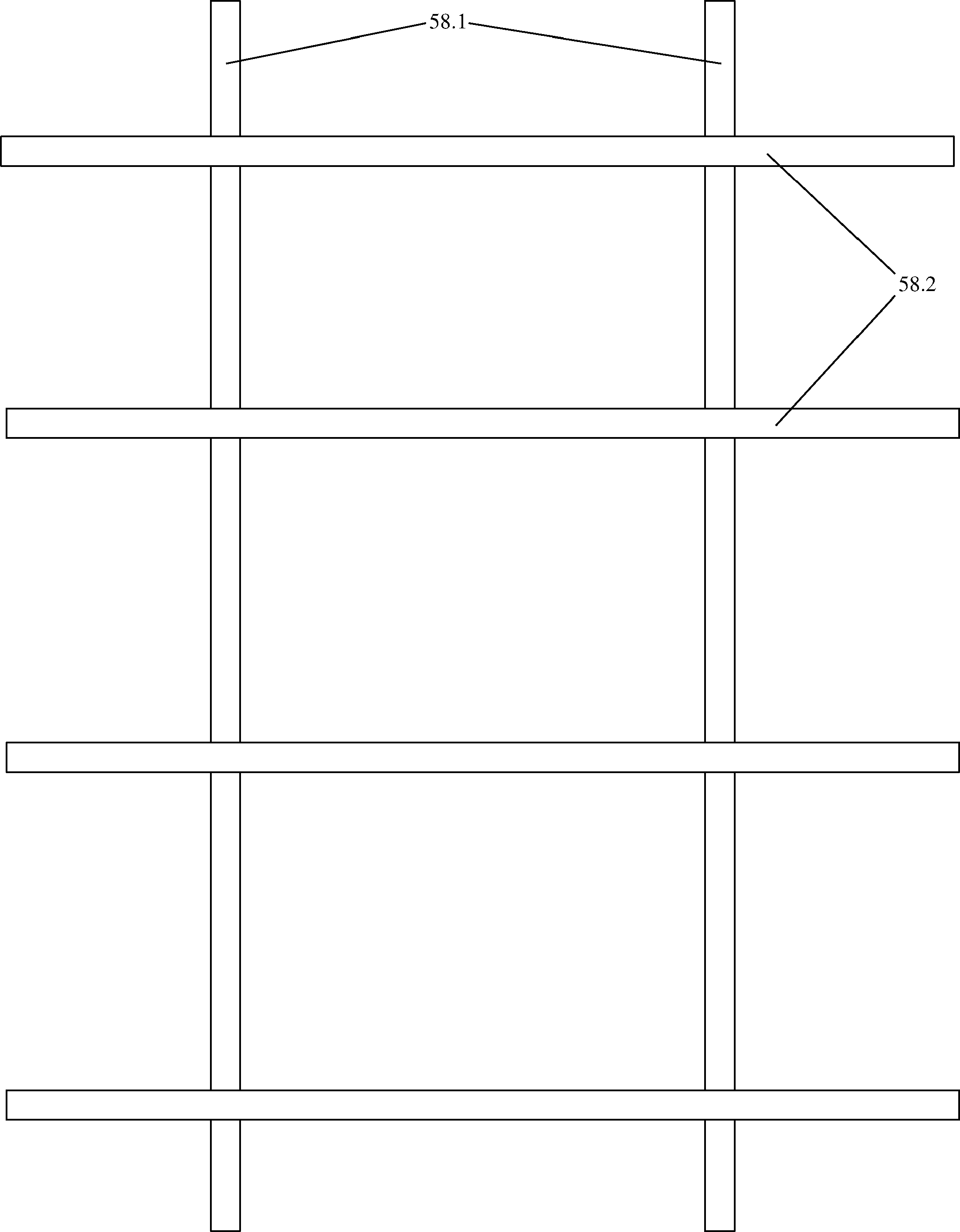
The horizontal elements [58.2] of all the above described embodiments should preferably project from both sides of the vertically positioned elements [58.1] situated at the extremities of the horizontally positioned elements [58.2]. Therefore, the horizontal elements [58.2] of all the above described embodiments should preferably also project from the outward-facing sides of the vertically positioned elements [58.1], which are inserted into the cavities positioned at the extremities of these [58.2]. This design feature will further increase the surface area provided by the horizontal elements [58.2].
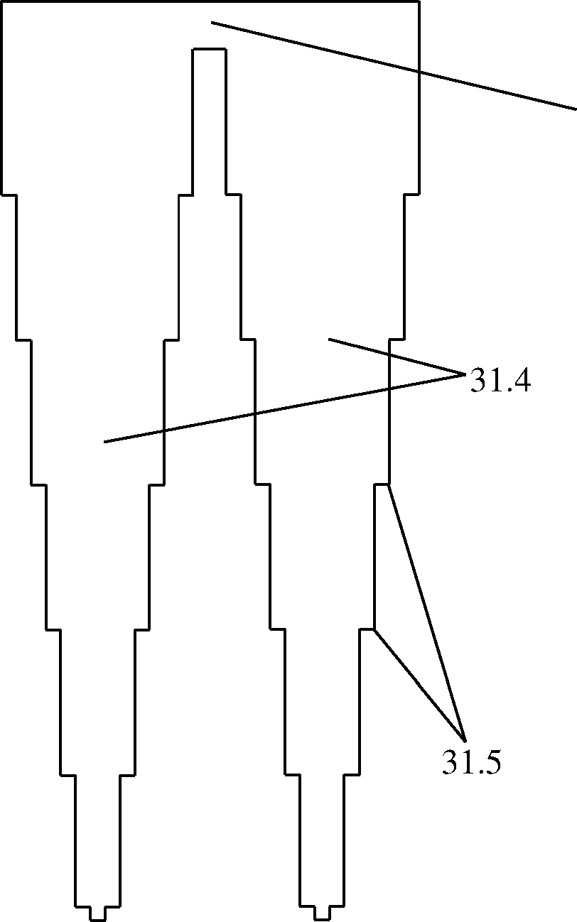
The outer [31.2] and inner [31.4] vertically positioned elements can comprise four step-like profiled geometries [31.1, 31.5] each, such that the inner vertical element [31.4] attaches two outer sets of stepped fields [31.5] to the other by an attaching member [31.3] and is hence inserted into the four inner stepped geometry sets [31.1] of the outer vertically positioned elements.
The horizontal elements [32.4], notably the designs comprised on Figures 10 and 12, can comprise a different design such that outer cavities which are perpendicular to the element’s [32.4] length [32.2] are positioned at any point along the inner cavity of an inner vertically positioned element positioned in parallel to the element’s [32.4] length [32.1]. This can be comprised along at least one of the sides of the element [32.4]. Therefore this design offers the advantage that any set of inner [32.3] and outer [32.2] cavities can be positioned perpendicularly to any inner cavity [32.1] which is parallel to the element’s [32.4] length, and at any position along it [32.1]. This feature is to be comprised on at least one of the element’s [32.4] two sides which are parallel to its [32.4] length. As a result, this design allows a set of vertical elements to be positioned perpendicular to the element’s [32.4] length such that these can be positioned at any position along an inner vertical element positioned in parallel to the element’s [32.4] length, along at least one of the two edges which are parallel to the element’s [32.4] length, hence maximising design and application flexibility, as well as the multifunctional flexibility of the piece of furniture concerned.
The mountable furniture system can also comprise horizontally positioned elements [32.4] which comprise outer cavities [32.5] which each form a single cavity with a neighbouring inner [32.1] and/or outer [32.7] cavity which is positioned in parallel to said horizontal elements’ [32.4] length. This means that the inner [32.6] and outer [32.5] cavities which house the outer vertically positioned elements [37.3] which are to be inserted perpendicularly to the element’s [32.4] length, allow these [37.3] to be positioned perpendicularly against an outer vertically positioned element [37.1] which is inserted into the outer cavities [32.7] which are positioned in parallel to said element’s [32.4] length. Therefore, at least one set of outer vertically positioned elements [37.3] can be positioned perpendicularly such that its [37.3] outer edges are positioned against at least one set of inner [37.2] and/or outer [37.1] vertically positioned elements which are positioned in parallel to the length of said horizontally positioned elements [32.4]. The inner vertical elements [37.4] are inserted into the inner cavities [32.6] as previously explained.
The mountable furniture system can also comprise a configuration wherein the outer vertically positioned elements [37.3] which are positioned in parallel to the horizontal elements’ width, are positioned perpendicularly against the outer vertically positioned elements [37.1] which are positioned in parallel to the horizontal elements’ length, hence comprising horizontally positioned elements which comprise a T-shaped cavity [33.1, 33.2] at least at one comer, which should preferably be open [33.1] along the width’s edge of said horizontally positioned elements. The outer vertical elements which are positioned perpendicularly to the horizontal element’s length [37.3] are inserted into the outer cavities [33.2] , whose edges hence contact the outer vertical elements [37.1] which are positioned perpendicularly to the horizontal elements’ length. The parallel positioned vertical elements [37.3] are inserted into the open outer cavities [33.1]. Said cavity [33.1] makes a single open cavity with the perpendicular positioned neighbouring outer cavity [33.2] at each comer. The inner vertical elements [37.4, 37.2] are inserted into their respective inner cavities [33.4,
33.3],
The mountable furniture system can also comprise a configuration wherein the outer vertically positioned elements [38.3] which are positioned in parallel to the horizontal elements’ length, are positioned perpendicularly against the outer vertically positioned elements [38.1] which are positioned in parallel to the horizontal elements’ width, hence comprising horizontally positioned elements which comprise a T-shaped cavity [34.1, 34.2] at least at one comer, which should preferably be open [34.1] along the length of said horizontally positioned elements. The outer vertical elements which are positioned perpendicularly to the horizontal element’s length [38.1] are inserted into the outer cavities [34.1], which are perpendicularly in contact with the edges of the outer vertical elements [38.3] which are positioned in parallel to the horizontal elements’ length. The perpendicularly positioned vertical elements [38.1] are inserted into the open outer cavities [34.1]. Said cavity [34.1] makes a single open cavity with the neighbouring parallel positioned outer cavity [34.2] at each comer. The inner vertical elements [38.2, 38.4] are inserted into their respective inner cavities [34.3, 34.4].
The mountable furniture system concerned can comprise outer cavities [35.2, 36.3] along at least one side of said horizontal elements, hence offering the possibility to insert outer vertically positioned elements in parallel to at least one of the horizontal elements’ sides, and therefore offering the possibility to insert at least one set of inner and outer vertically positioned elements in parallel to any of the horizontal elements’ edges. The cavities should be positioned between at least two inner cavities [35.1] in order to insert inner vertical elements. The comers can feature closed half T-shaped geometries as previously explained, or opened T-shaped geometries [36.1, 36.4] as on Figure 34.
So, if the outer vertically positioned elements [39.3, 40.3] can be inserted one beside the other into the same outer cavity [35.2, 36.3] along any of the edges of the horizontally positioned elements. So, each outer cavity [35.2, 36.3] along any of the edges can house at least one half of an outer vertically positioned element each, preferably two [39.3, 40.3]. The other half parts of the vertically positioned elements [39.1, 40.5] are inserted into the other outer cavities. The outer [39.4, 40.1] and inner [39.5, 40.2] vertically positioned elements which are positioned perpendicularly to the horizontal element’ length, are inserted into different cavities, which can be either connected to said outer cavities [35.2, 36.3] or not.
The mountable furniture system concerned can also comprise at least one horizontally positioned element [41.2] which projects through part of the entire length of other horizontally positioned elements [41.4], in which at least one set of vertically positioned elements [41.1] is inserted between at least two horizontally positioned elements [41.4].
Furthermore, said mountable furniture system can also comprise at least one set of vertically positioned elements [41.3] inserted through at least one horizontally positioned element [41.4] which is positioned over at least one horizontally positioned element underneath [41.5] and/or under at least one horizontally positioned element [41.6] positioned over it.
The mountable furniture system concerned can also comprise at least one vertically positioned element [42.2] and/or at least one horizontally positioned element [52.1], which all can comprise outward projecting profiles [42.1, 52.2] which sustains said elements [42.2,
52.1] in their required positions, which are to be inserted into cavities of between the inner and outer the vertically positioned elements [53.2] and/or into the cavities comprised in the horizontally [53.3] positioned elements. So, the horizontally [53.4] and vertically [53.1] positioned elements can be sustained into their required positions by comprising outer projecting profiles [42.1, 52.2], hence being sustained by the outer sets of vertically [53.2] and horizontally [53.3] positioned elements.
In the case of the vertically positioned elements [42.2], their respective outward projecting profiles [42.1] are inserted into the cavities [55.2] which are comprised in the upper and lower horizontally positioned elements [53.3] in between which said vertical elements [42.2] are positioned. The upper and lower horizontal elements [53.3] comprise inner [55.1] and outer [55.3] cavities as previously explained in order to keep those into their required position in turn.
In the case of the horizontally positioned elements [53.4], these [50.4] can be inserted into the inner steps of the outer vertically positioned elements [50.1]. This operation is to be performed after inserting the bottom horizontal element [50.4] and before inserting the top horizontal element [50.2]. The bottom [50.4] and top [50.2] horizontal elements comprise inner [55.1] and outer [55.3] cavities in order to keep the vertically positioned elements into the required position, and hence keeping said horizontal elements [50.3, 52.1] inserted between the top [50.2] and bottom [50.4] ones in their required position. Finally, the inner vertically positioned element [51.5] is then inserted, hence guaranteeing maximum stability of the furniture piece concerned. The inner vertical element [51.5] is inserted through the inner cavities of the upper [51.2] and lower [51.4] horizontal elements and is hence inserted between the inner stepped profiles of the outer vertical elements [51.1], hence keeping the other horizontally position elements [51.3, 52.1] in their required positions.
Said mounting system is very suitable to be used in the configuration described in the previous paragraph, which describes the architecture comprised on Figure 41.
Alternatively, the outer [54.3] and inner [54.4] vertically positioned elements can comprise outward projecting geometries [54.1, 54.5, 54.2] positioned along their upper and lower edges. The outer vertically positioned elements [54.3] can comprise such geometries along both the top [54.1] and bottom [54.5] sides, while the inner vertically positioned elements [54.4] should preferably comprise these [54.2] only along their top edges. These elements [54.3, 54.4] can hence form a set of vertically positioned elements [53.1] which can be inserted between the outer sets of horizontally positioned elements [53.3]. These outward projecting profiles [54.1, 54.5, 54.2] are hence inserted into the cavities [55.2] present in the horizontally positioned elements between which these [54.1, 54.5, 54.2] are positioned, hence keeping these [54.1, 54.5, 54.2] in their required vertical positions.
The mountable furniture system concerned can also comprise door panels [45.2] which each can comprise a hollow handle [45.3], and which each comprises outward projecting profile at the upper edges [45.1] of said doors and outward projecting elements at the lower edges [45.4] of said doors, hence forming hinges [45.1, 45.4]. Said outward projecting profiles [45.1, 45.4] are to be inserted into open cavities [44.5] of at least one horizontally positioned element being positioned along each of said edges of said door panels [45.2]. After being inserted into said opened outer cavities [44.5]. Said outward projecting profiles [45.1, 45.4] are finally inserted into opened curved profiles [44.4], which are connected to said outer opened cavities [44.5]. Said curved profiles [44.4] are positioned adjacent to said opened outer cavities [44.5] in order for the user to install said door panels [45.2] easily. Said curved profiles [44.4] are designed in order for the projecting profiles [45.1, 45.4] to be able to rotate perpendicularly to the plane of said horizontally positioned element where said open cavity profiles [44.4] are positioned.
Said opened cavity profiles [44.4] are rounded at the inner edges, and are connected to the outer cavity profiles [44.5], which are situated along the edges of said door panels [45.2].
The horizontally positioned elements to which the door panels [45.2] are attached also comprise inner cavities which are perpendicular to the element’s length [44.1], and inner [44.2] and outer [44.3] cavities which are positioned in parallel to the element’s length along the opposite edge to that at which said door panels [45.2] are positioned. Said inner [44.2] and outer [44.3] cavities which are positioned along the element’s length, are designed to house the inner and outer vertically positioned elements respectively, which the furniture piece concerned closed when it is all mounted, with said door panels [45.2] included.
The curved open profiles [44.4] which are situated laterally to the outer open cavities [44.5] of the horizontally positioned elements, which are positioned perpendicularly to the length of said door panels [45.2].
So, said furniture piece can comprise the door panels [43.1] whose outer projecting elements [45.1, 45.4] are inserted and positioned into said half-rounded cavities [44.4] of the top [43.2] and bottom [43.5] horizontally positioned elements. The inner horizontally positioned elements [43.4] hence comprise a smaller width in order for the door panels [43.1] to fit in front of them, while the vertically positioned elements [43.3] are positioned into the outer [44.5] and inner [44.1] cavities, hence maintaining the outer projecting profiles [45.1, 45.4] of the door panels [43.1] in their required positions.
The mountable furniture system concerned can also comprise at least one sliding door panel [46.1] which is kept in its required position by being inserted into hollow channels [48.6] of at least one horizontally positioned element [46.2] on top and one horizontally positioned element [46.2] at the bottom, preferably at least two sliding door panels [46.1] which should preferably each be inserted in separated lower and upper hollow channels [48.6], in which said sliding doors [46.1] should preferably comprise hollow handles [46.4] and inner rightangular profiles such that these would fit into the hollow channels [48.6] while simultaneously being as displaceable as possible towards the outer or inner vertical elements [46.5] ,
The system concerned in the previous paragraph offers a very high practicability and ease of mounting. During the mounting process, the lower horizontally positioned elements [46.3,
47.5] are initially inserted into the two outer or inner vertical elements [46.5]. Then, a horizontally positioned element [46.2, 48.5] comprising a set of hollow channels [48.6] is inserted on the previously inserted horizontal element [46.3, 47.5]. Then, a sliding panel [46.1] is inserted into each of the hollow channels [48.6] respectively. Then, at the next step of the outer or inner vertical elements [46.5], a horizontally positioned element [46.2, 48.5] comprising hollow channels [48.6], followed by a horizontally positioned element [46.3,
47.5] without channels, followed by another horizontal element [46.2, 48.5] with a set of hollow channels [48.6]. Then, a set of sliding door panels [46.1] is inserted into said hollow channels [48.6] of the last horizontal element [4.2, 47.5] which was inserted. The previously described mounting procedure is continued until the last set of door panels [46.1] are inserted, followed by the top horizontal element [46.2, 48.5] with hollow channels [48.6], and finally followed by the last horizontal element [47.5], which is the highest positioned horizontal element to be inserted. The horizontal elements without channels [47.5] are positioned below and on top of the sliding door panels [46.1] and the corresponding channelled [48.6] horizontal elements [48.5] in order to maintain said sliding door panels in their required positions. The final step comprises the insertion of the inner or outer vertical elements [46.5] into the vertical elements on which the horizontal elements [46.2, 46.3] are sustained. If these are the outer vertical elements [46.5], then, the final step includes the insertion of the inner vertical elements [46.5]. However if said vertical elements [46.5] are sustained on the inner vertical elements, then, the final step comprises the insertion of the outer vertical elements [46.5],
While inserting the channelled [48.6] horizontal elements [48.5] on top of the sliding panels [46.1], the upper parts [49.2] of said sliding door panels [46.1] are each simultaneously inserted into their required hollow channels [48.6] respectively, such that these [46.1] are inserted into their required respective hollow channels [48.6].
Said sliding door panels [46.1, 49.1] should preferably comprise hollow handles [46.4, 49.3] in order to offer an easy way to displace them for the user. When inserting these [46.2, 49.3] into their required positions, the upper [49.2] and lower areas [49.4] are inserted into their respective upper and lower hollow channels [48.6] respectively. As due to structural stability reasons it is recommended that the hollow channels [48.6] do not project up to the vertical elements [46.5], the door panels [46.1, 49.1] should therefore preferably comprise cut steplike inner profiles [49.2, 49.4] at each of their upper [49.2] and lower [49.4] areas respectively, such that the sliding door panels [46.1, 49.1] can be displaced until making contact with the vertically positioned elements [46.5] of the piece of furniture concerned.
This leads to the inner volumes of the piece of furniture being fully closed when required.
This configuration allows the upper [49.2] and lower [49.4] areas of the door panels [46.1,
49.1] to be positioned inside the upper and lower hollow channels [48.6] respectively, while allowing the upper [49.2] and lower [49.4] inner step-like profiles to be positioned between the end of the upper and lower channels [48.6] and the vertically positioned elements [46.5],
The horizontally positioned elements [46.2, 46.3], including the hollow channelled ones [46.2, 48.5] and the even ones [46.3, 47.5], each comprise the T-shaped profiles [47.1, 48.1] which should preferably be open for presentation purposes. Said T-shaped profiles [47.1,
48.1] house the outer vertical elements which are positioned both in parallel and perpendicular to the length said horizontal elements [46.2, 46.3, 47.5, 48.5]. These [46.2,
46.3, 47.5, 48.5] also comprise inner cavities [47.3, 48.3] which house the inner vertical elements which are positioned perpendicular to their [46.2, 46.3, 47.5, 48.5] length. These [46.2, 46.3, 47.5, 48.5] also comprise inner cavities [47.2, 48.2] which house the inner vertical elements which are positioned in parallel to their [46.2, 46.3, 47.5, 48.5] length.
The mountable furniture system concerned can also comprise outer stepped profiled vertically and/or horizontally positioned elements [54.3, 54.4] and/or inner stepped geometrised vertically and/or horizontally positioned elements [54.3, 54.4], which comprise outward projecting geometries [54.1, 54.2, 54.5] along their upper and/or lower horizontally orientated edges, which are to be inserted into cavities situated along the surface of the horizontally [53.3] and/or vertically [53.2] positioned elements. This means that the inner stepped elements [54.4] can comprise outward projecting profiles [54.2] along its top edge [54.2] , whereas the outer stepped elements [54.3] can comprise outward projecting profiles [54.1, 54.5] along both of its end edges [54.1, 54.5]. This means that in the case of the outer stepped elements [54.3], outward projecting profiles along its top edge [54.1] and outward projecting profiles along its bottom edge [54.5]. This is because the outer stepped elements [54.3] can make contact with both top and bottom horizontal elements [53.3] and/or both laterally positioned vertical elements [53.2]. This hence means that said set of stepped elements [54.3, 54.4] can be positioned vertically [53.1] or horizontally [53.4], hence being sustained by inserting said outward projecting profiles [54.2, 54.1, 54.5] into the corresponding cavities [55.2] in the sustaining vertical elements [53.2] and/or in the sustaining top and bottom horizontal elements [53.3]. This design hence offers greater design and functional flexibility for any furniture piece which comprises the mounting system concerned. The sustaining vertical [53.1] and/or vertical elements [53.3] comprise the cavities [55.2] in order to sustain the outward projecting profiles [52.2] of said sustained vertical [53.1] and/or horizontal [53.4] elements.
The mountable furniture system concerned can also comprise at least one horizontally positioned element [56.4] in which at least one side [56.4] is positioned between at least two inner right-angular profiles [56.6], in which at least one is situated at each of said horizontal element’s sides concerned [56.4], comprising open outer cavities [56.9] and closed inner cavities [56.10] on said side concerned and which is maintained in its required position by comprising said inner right-angular profiles [56.6] being connected together by a horizontal member [56.7], on which at least one inner vertically positioned element [56.2] which comprises corresponding outer right-angular profiles [56.1] is inserted, such that the inner geometries [56.5, 56.6, 56.1] of said system are fully covered by said inner vertically positioned elements [56.2], which are positioned in parallel to said connected inner rightangular profiles [56.5, 56.6, 56.1], hence shaping a table-like furniture piece.
The design concerned in the previous paragraph comprises at least two outer vertical elements [56.8] comprising two vertical profiles which comprise each an inner step-like cut profile [56.6] their [56.8] top areas [56.5] and which are connected together by a horizontal connecting element [56.7], at least one horizontally positioned element [56.4] comprising outer [56.9] and inner [56.10] cavities, and one inner vertical element [56.2] for each of the outer vertical elements [56.8] comprised. Each set of vertically positioned elements comprises at least two vertical members [56.8] which are connected together by a horizontal member [56.7]. Each inner vertical element [56.2] comprises at least one outer step-like profile [56.1] along each outer edge of said inner vertical element [56.2].
The mounting procedure of the piece of furniture concerned on Figure 56 comprises only two steps. The first step includes the insertion of the horizontally positioned element (or elements) [56.4] into the inner step-like profiles [56.6] of the vertical member [56.8] of each vertical element, hence positioning the members [56.3] which divide the inner [56.9] from the outer [56.10] cavities at said horizontal element (or elements) [56.4], such that said members [56.3] at each side of said horizontal element (or elements) [56.4] are positioned between the steplike cut [56.6] upper profiles [56.5] of said vertical elements’ vertical members [56.8]. This hence results in the insertion of the outer cavities [56.9] of said horizontal element (or elements) [56.4] into the upper profiles [56.5] of said vertical members [56.8].
The second step includes the insertion of the outer step-like cut profiles [56.1] of each inner vertical element [56.2] on each of the connecting members [56.3] of each horizontal element [56.4] , hence inserting the outer step-like cut profiles [56.1] of said inner vertical elements [56.2] in between the upper profiles [56.5] of said vertical members [56.8] of each vertical element. In order for said piece of furniture to offer the highest levels of presentation, when inserting said inner vertical elements [56.2], the lower edges [56.13] of each of said inner vertical elements [56.2] are positioned on the upper edges [56.11] of the horizontal connecting member [56.7] which connects said vertical members [56.8] together. This configuration also maximises structural stability of the piece of furniture concerned. In order to maximise comfort of use and practicability of the piece of furniture concerned, when positioning said inner vertical elements [56.2], these [56.2] are designed such that their [56.2] upper edges [56.14] result to be at an equal height to that of the upper surfaces [56.12] of the highest positioned of said horizontal elements [56.4], such that said furniture piece could be used as a table which offers an even surface [57.5] from each end to the other opposite end without any changes in height along said surface [57.5]. This mounting system hence results to a table-like furniture piece which should preferably be used for tabling applications, comprising the horizontal element (or elements) [57.3] being positioned in between the vertical members [57.4] at each opposite side, and with an inner vertical element [57.2] positioned between said vertical members [57.4] with its upper outward right-angled profiles [57.1] being positioned between the top profiles of said vertical members [57.4].
The piece of furniture concerned on Figures 56 and 57 should preferably comprise two vertical elements comprising each two vertical members [57.4] connected together by a horizontal member [56.7]. Said furniture piece should preferably comprise one or two horizontally positioned elements [57.3] positioned one on top of the other if the number of horizontal elements [57.3] present is greater than one.
In all the above described embodiments, the horizontally positioned elements [58.2] can also be positioned vertically [58.1] while hence positioning the vertically positioned elements [58.1] horizontally [58.2]. This means that the design features comprised in the vertically positioned elements [58.1] can be comprised in the horizontal elements [58.2], while the design features comprised in the horizontally positioned elements [58.2] can be comprised in the vertical elements [58.1], hence maximising furniture design flexibility and multifunctional flexibility.
In all the above described embodiments, the mounting process can also be such that the horizontally positioned elements [25.2, 58.2] are initially inserted into the inner vertically positioned elements [25.3, 58.1], and the outer vertically positioned elements [25.1, 58.1] are finally inserted as the final mounting operation of the piece of furniture concerned. This hence means that the vertically positioned elements [25.1, 25.3, 58.1] are positioned upside down compared to the previously described configuration.
Said furniture system comprises more features, which are important for stability and ease of insertion of the vertical members.
Said outer (63.1) and inner (64.1) vertical members comprise a lower cut geometry which comprises the lowest section (63.3, 64.4) which is lower in width tan the distance between the two upper walls (63.4, 64.2) of said lower geometry, hence comprising a lower geometry with inward inclined walls (63.2, 64.3) at the lower cut end geometries of both inner (64.1) and outer (63.1) vertical members, which hence can fit and insert into each other’s cavities.
On said furniture system, at least one outer vertical member (62.3, 62.6, 61.5) inserts into a set of two separate outer cavities (59.5, 60.6) which each connect to each of the horizontal member side’s middle section (59.3, 60.1), in which inner vertical members (61.3, 62.1) insert beside the perpendicularly positioned outer vertical members (61.2, 61.3, 62.1, 62.5), such that said outer vertical members (62.3, 62.6, 61.5) are inserted through the middle of the horizontal members (59.1, 60.2, 61.1, 62.2), which comprise a set of at least one inner vertical member (61.4, 62.4) positioned inside a rectangular cavity (59.4, 60.4) positioned between said outer cavities (59.5, 60.6).
The outer cavities (60.3) insert two outer member components (62.3) if said vertical members (62.6, 62.4) are positioned in a plurality beside each other through a line of cavities (60.3,
60.4, 60.6) and inserted through the middle of said horizontal members (59.1, 60.2, 61.1,
62.2).
Said furniture system comprises horizontal members (59.1, 61.1) which comprise rectangular cavities for inner (59.4) and outer (59.5) vertical member insertion along the centre line of said members (59.1, 61.1), such that said outer cavities (59.5) connect to the inner cavities (59.3) of the perpendicularly positioned vertical members. Said perpendicular connecting inner cavity (59.3) is positioned along the end edge of said horizontal member (59.1, 61.1), and are hence between the two outer perpendicular cavities (59.2). Said perpendicularly positioned cavities (59.2, 59.3) are positioned along the edges of each side of said horizontal member (59.1, 61.1).
Said mid inserted outer (61.5) and inner (61.4) vertical members maximise stability of the furniture system, as the edges of said outer vertical members (61.5) do not allow the perpendicularly positioned inner members (63.1) to move from one side to the other, hence guaranteeing a stable structure. The outer perpendicularly positioned members (61.2) follow the pattern, as these (61.2) are always inserted between the edges of said inner members (61.3) .
Said furniture system can also comprises horizontal members (60.2, 62.2) which comprise a plurality of rectangular cavities for inner (60.4) and outer (60.6) vertical member insertion along the centre line of said members (60.2, 62.2), such that said outer cavities (60.6) connect to the inner cavities (60.1) of the perpendicularly positioned vertical members. Said perpendicular connecting inner cavity (60.1) is positioned along the end edge of said horizontal member (60.2, 62.2), and are hence between the two outer perpendicular cavities (60.5). Said perpendicularly positioned cavities (60.1, 60.5) are positioned along the edges of each side of said horizontal member (60.2, 62.2). Sid horizontal member (60.2, 62.2) comprises at least two inner (60.4) cavities, hence meaning that a cavity (60.3) positioned between each two inner cavities (60.4), is comprised in order to insert the two ends of the outer vertical members (62.4) when these are being inserted into the respective cavities (60.6,
60.3).
Said mid inserted outer (62.3, 62.6) and inner (62.4) vertical members maximise stability of the furniture system, as the edges of said outer vertical members (62.3, 62.6) do not allow the perpendicularly positioned inner members (62.1) to move from one side to the other, hence guaranteeing a stable structure. The outer perpendicularly positioned members (62.5) follow the pattern, as these (62.5) are always inserted between the edges of said inner members (62.1).
The inner members (61.4, 62.4) positioned along the middle of said horizontal members (61.1, 62.2) are inserted between said outer members (61.5, 62.3, 62.6) after inserting these (61.5, 62.3, 62.6), hence maximising the structural stability of the furniture system and maximising the good looking of the furniture structure.
So, the inner perpendicular vertical members (61.3, 62.1) are inserted into the respective inner cavities (59.3, 60.1), while said outer perpendicular vertical members (61.2, 62.5) are inserted into the respective outer cavities (59.2, 60.5). The mid positioned inner vertical members (61.4, 62.4) are inserted into the respective inner mid positioned cavities (59.4,
60.4). The corresponding outer mid positioned vertical members (61.5, 62.3, 62.6) are inserted into the respective outer (59.5, 60.6) cavities, and into the respective share outer cavities (60.3) which are positioned between two inner mid positioned cavities (60.4) if the mid positioned vertical members (62.3, 62.4, 62.6) are comprised as a plurality.
Said mid positioned vertical members (61.4, 61.5, 62.3, 62.4, 62.6) are inserted and hence positioned through the entire mid length of said horizontal members (59.1, 60.2, 61.1, 62.2), and perpendicularly to said perpendicular inner (61.3, 62.1) and outer (61.2, 62.5) members.
Said outer (63.1) and inner (64.1) members comprise inclined wall geometries, with side walls which are inclined inwards while projecting down said members (63.1, 64.1), hence projecting partly inwards for both inner (64.1) and outer (63.1) members. So, in the case of the outer vertical members (63.1), the inner walls have said configuration, while in the case of the inner vertical members (64.1), the outer walls have said configuration. This design characteristic maximises the ease of inserting of the members (63.1, 64.1) into the other for the consumer.
Said configuration is also comprised at the lower section (63.2, 64.3) of both members (63.1,
64.1) , where a vertical wall (63.4, 64.2) is comprised at the upper area of said section, in order to insert one member into the other (63.1, 64.1), and maximises the furniture’s structural stability. However, the lower part comprises two inwardly inclined walls (63.2,
64.3) which project partly inwards (63.2, 64.3), hence resulting in the lowest part (63.3, 64.4) of the cut geometry of both members (63.1, 64.1) comprising a lower horizontal width (63.3,
64.4) than that between the two upper walls (63.4, 64.2). This feature is comprised on the inner walls (63.2, 63.3, 63.4) of the outer vertical members (63.1), while also being comprised in exactly the same matching profile along the outer walls (64.2, 64.3, 64.4) of the inner vertical members (64.1).
So, both inner (64.1) and outer (63.1) vertical members comprise the same inward projecting matching profile (63.3, 64.4), comprised on the inner edges for the outer members (63.1), and comprised on the outer edges for the inner members (64.1), hence both comprising outer (64.3) and inner (63.2) wall geometries which project vertically (63.4, 64.2) and partly inwards (63.2, 64.3) at the bottom part, until reaching the bottom edge (63.3, 64.4).
These two wall geometries (63.4, 64.2, 63.2, 64.3) match together when the two vertical members (63.1, 64.1) are inserted into each other, such that said vertical members (63.1,
64.1) are hence designed to be inserted into each other when inserting said outer (63.1) and inner (64.1) members into the corresponding hollow geometries of the corresponding horizontal members (59.1, 60.2, 61.1, 62.2).
Said outer lower walls (64.2) of the inner vertical members (64.1) are vertically projecting such that these (64.2) are designed to insert into said inner lower walls (63.4) of the outer vertical members (63.1), such that these (63.4) are also vertically projecting.
This feature will maximise ease of insertion of both inner (64.1) and outer (63.1) vertical members into the corresponding horizontal members for the consumer.
The furniture mounting systems concerned in this invention can be used in all types of furniture and furnishings. It should be preferably used for bookcases and tables. The features comprised on Figures 59-62 should be preferably used for tables, as these (Figures 59-62) are especially designed to maximise stability to furniture designs and structures which shape in the form of tables and/or table like furniture structures.
So, the present invention comprises a mountable furniture system which comprises a set of at least one outer rectangular cavity at each inner side of the at least one horizontally positioned member having at least one outer hollow slot at each corner and/or along each of the member’s sides, which comprises an opened profile and/or a closed profile on the member’s surface, which inserts into at least an inner stair-profiled geometry of at least one outer vertically positioned member, into which finally an inner vertically positioned member comprising a matching outer stair-profiled geometry, inserts into said inner stair-profiled geometry of each of said outer vertically positioned members, such that said outer (63.1) and inner (64.1) vertical members comprise a lower cut geometry which comprises the lowest section (63.3, 64.4) which is lower in width tan the distance between the two upper walls (63.4, 64.2) of said lower geometry, hence comprising a lower geometry with inward inclined walls (63.2, 64.3) at the lower cut end geometries of both inner (64.1) and outer (63.1) vertical members, which hence can fit and insert into each other’s cavities, such that on said furniture system, at least one outer vertical member (62.3, 62.6, 61.5) inserts into a set of two separate outer cavities (59.5, 60.6) which each connect to each of the horizontal member side’s middle section (59.3, 60.1), in which inner vertical members (61.3, 62.1) insert beside the perpendicularly positioned outer vertical members (61.2, 61.3, 62.1, 62.5), such that said outer vertical members (62.3, 62.6, 61.5) are inserted through the middle of the horizontal members (59.1, 60.2, 61.1, 62.2), which comprise a set of at least one inner vertical member (61.4, 62.4) positioned inside a rectangular cavity (59.4, 60.4) positioned between said outer cavities (59.5, 60.6), such that the outer cavities (60.3) insert two outer member components (62.3) if said vertical members (62.6, 62.4) are positioned in a plurality beside each other through a line of cavities (60.3, 60.4, 60.6) and inserted through the middle of said horizontal members (59.1, 60.2, 61.1, 62.2).
The preferred embodiments are the following.
A mountable furniture system according to the above in which an inner vertically positioned member having a stair-like geometry on each of its two outer edges, is inserted into the central hollow slots of the horizontally positioned members, such that the lateral hollow slots of the outer vertically positioned members are fully covered.
A mountable furniture system according to the above which comprises at least one horizontally positioned member comprising at least one inner hollow slot at each side, which is preferably positioned parallel to at least one of the horizontal members’ edges or perpendicular to at least one of the horizontal members’ edges, and which inserts into at least an outer step profiled part of at least one vertically positioned member.
A mountable furniture system according to the above in which an outer vertically positioned member having a stair-like geometry on each of its two inner edges, is inserted into the outer hollow slots of the horizontally positioned members, such that the stability of the horizontal members is maximised.
A mountable furniture system according to the above comprising horizontally positioned members which have different inner and outer hollow slot lengths each, according to the distance between each of the two steps featured at each level of the vertically positioned members.
A mountable furniture system according to the above which comprises horizontally positioned members having inner hollow slot lengths which correspond to the distance between each outer step at each level of the inner vertically positioned members.
A mountable furniture system according to the above which comprises horizontally positioned members having outer hollow slot lengths which correspond to the distance between each inner step at each level of the outer vertically positioned members.
A mountable furniture system according to the above wherein the horizontally positioned members comprise at least one outer hollow slot which comprises a T-shaped opened or closed profile joining together outer hollow slot profiles only or a combination of inner and outer hollow slot profiles, and/or at least one half T-shaped opened or closed profile at each corner, and which are sustained by at least 3 inner vertically positioned members housed in at least three outer vertically positioned members.
A mountable furniture system according to the above which comprises said members of the above in which the outer vertically positioned members which are positioned perpendicular to the horizontal members’ length, are positioned perpendicularly against the edge of the outer vertically positioned members which are positioned in parallel to the horizontal members’ length, or vice-versa, and wherein the horizontal members project from both sides of at least one set of vertically positioned members along the horizontal members’ length.
A mountable furniture system according to the above wherein the vertical profiles of the inner stepped geometries of the outer vertically positioned members and the vertical profiles of the outer stepped geometries of the inner vertically positioned members are profiled as inclined lined profiles which preferably become vertically lined profiles at the areas of contact with the horizontally positioned members.
A mountable furniture system according to the above wherein the inner and vertically positioned members comprise only one stepped profile each such that each of these are inserted in two pieces in their respective corresponding horizontal hollow slots, or wherein these comprise four stepped geometries each such that each of these is instead as a single piece component housed inside the other.
A mountable furniture system according to the above which comprise a flexible attaching member, preferably a clamp system, on at least one side, preferably two sides, of the bottom or top ends of one of the vertically positioned members which preferably forms a single piece component with it, and inserts into a hollow slot profile on at least one side, preferably two sides, of the bottom or top ends of the other vertically positioned member in which it is housed.
A mountable furniture system according to the above wherein said inner and outer vertically positioned members are positioned horizontally and said horizontally positioned members are positioned vertically, and wherein the number of horizontally positioned steps on each of the stepped edges of the vertically positioned members range from 2 to 30, preferably from 3 to
12, and more preferably from 4 to 7.
A mountable furniture system according to the above which is made of materials such as wood, MDF, plywood and/or plastic, preferably PVC or a polyolefin.
A mountable furniture system according to the above in which members are manufactured by machining, preferably cutting, of sheets of material to the required profiles, such as laser cutting and/or profiling, or by plastic injection processes.
A mountable furniture system according to the above comprised in shelves, shelving members, bookcases, closets, cupboards, curio cabinets, hutches, pantries, chests, chests of drawers, hope chests, dressers, coat racks, filing cabinets, nightstands, ottomans, sideboards, buffets, safes, umbrella stands, wardrobes, armoires, wine racks, chairs, fauteuils, recliners, chaise longue, stools, benches, sofas, divans, love seats, beds, daybeds, futons, headboards, infant beds, sofa beds, tables, billiard tables, chess tables, dining tables, night tables, coffee tables, drop-leaf tables, end tables, folding tables, gateleg tables, poker tables, trestle tables,
TV tray tables, wine tables, entertainment centres, changing tables, desks, davenport desks, drawing boards, computer desks, writing desks, monks benches, workbenches, bedroom sets, dinettes, dining sets, vanity sets, built-in furniture, campaign furniture, folding screens, work furniture, garden furniture, partitions, furnished lamps, clothes valets, tatami mats used for seating, drapes, aquarium furniture, doors, door furniture, windows, hutches, park furniture, picnic tables, stadium seating, street furniture, sword furniture, furniture finishings.
Preferred embodiments:
Shelves, shelving elements, bookcases, closets, cupboards, curio cabinets, hutches, pantries, chests, chests of drawers, hope chests, dressers, coat racks, filing cabinets, nightstands, ottomans, sideboards, buffets, safes, umbrella stands, wardrobes, armoires, wine racks, chairs, fauteuils, recliners, chaise longue, stools, benches, sofas, divans, love seats, beds, daybeds, futons, headboards, infant beds, sofa beds, tables, billiard tables, chess tables, dining tables, night tables, coffee tables, drop-leaf tables, end tables, folding tables, gateleg tables, poker tables, trestle tables, TV tray tables, wine tables, entertainment centres, changing tables, desks, davenport desks, drawing boards, computer desks, writing desks, monks benches, workbenches, bedroom sets, dinettes, dining sets, vanity sets, built-in furniture, campaign furniture, folding screens, work furniture, garden furniture, partitions, furnished lamps, clothes valets, tatami mats used for seating, drapes, aquarium furniture, doors, door furniture, windows, hutches, park furniture, picnic tables, stadium seating, street furniture, sword furniture, furniture finishings, accommodation, houses, buildings.
Claims (16)
- Claims:1) a mountable furniture system which comprises a set of at least one outer rectangular cavity at each inner side of the at least one horizontally positioned member having at least one outer hollow slot at each comer and/or along each of the member’s sides, which comprises an opened profile and/or a closed profile on the member’s surface, which inserts into at least an inner stair-profiled geometry of at least one outer vertically positioned member, into which finally an inner vertically positioned member comprising a matching outer stair-profiled geometry, inserts into said inner stair-profiled geometry of each of said outer vertically positioned members, such that said outer (63.1) and inner (64.1) vertical members comprise a lower cut geometry which comprises the lowest section (63.3, 64.4) which is lower in width tan the distance between the two upper walls (63.4, 64.2) of said lower geometry, hence comprising a lower geometry with inward inclined walls (63.2, 64.3) at the lower cut end geometries of both inner (64.1) and outer (63.1) vertical members, which hence can fit and insert into each other’s cavities, such that on said furniture system, at least one outer vertical member (62.3, 62.6, 61.5) inserts into a set of two separate outer cavities (59.5, 60.6) which each connect to each of the horizontal member side’s middle section (59.3, 60.1), in which inner vertical members (61.3, 62.1) insert beside the perpendicularly positioned outer vertical members (61.2,61.3, 62.1, 62.5), such that said outer vertical members (62.3, 62.6, 61.5) are inserted through the middle of the horizontal members (59.1, 60.2, 61.1, 62.2), which comprise a set of at least one inner vertical member (61.4, 62.4) positioned inside a rectangular cavity (59.4, 60.4) positioned between said outer cavities (59.5, 60.6), such that the outer cavities (60.3) insert two outer member components (62.3) if said vertical members (62.6,62.4) are positioned in a plurality beside each other through a line of cavities (60.3, 60.4,60.6) and inserted through the middle of said horizontal members (59.1, 60.2, 61.1, 62.2).
- 2) A mountable furniture system according to claim 1 in which an inner vertically positioned member having a stair-like geometry on each of its two outer edges, is inserted into the central hollow slots of the horizontally positioned members, such that the lateral hollow slots of the outer vertically positioned members are fully covered.
- 3) A mountable furniture system according to claims 1 to 2 which comprises at least one horizontally positioned member comprising at least one inner hollow slot at each side, which is preferably positioned parallel to at least one of the horizontal members’ edges or perpendicular to at least one of the horizontal members’ edges, and which inserts into at least an outer step profiled part of at least one vertically positioned member.
- 4) A mountable furniture system according to claims 1 to 3 in which an outer vertically positioned member having a stair-like geometry on each of its two inner edges, is inserted into the outer hollow slots of the horizontally positioned members, such that the stability of the horizontal members is maximised.
- 5) A mountable furniture system according to claims 1 to 4 comprising horizontally positioned members which have different inner and outer hollow slot lengths each, according to the distance between each of the two steps featured at each level of the vertically positioned members.
- 6) A mountable furniture system according to claims 1 to 5 which comprises horizontally positioned members having inner hollow slot lengths which correspond to the distance between each outer step at each level of the inner vertically positioned members.
- 7) A mountable furniture system according to claims 1 to 6 which comprises horizontally positioned members having outer hollow slot lengths which correspond to the distance between each inner step at each level of the outer vertically positioned members.
- 8) A mountable furniture system according to claims 1 to 7 wherein the horizontally positioned members comprise at least one outer hollow slot which comprises a T-shaped opened or closed profile joining together outer hollow slot profiles only or a combination of inner and outer hollow slot profiles, and/or at least one half T-shaped opened or closed profile at each corner, and which are sustained by at least 3 inner vertically positioned members housed in at least three outer vertically positioned members.
- 9) A mountable furniture system according to claims 1 to 8 which comprises said members of claim 8 in which the outer vertically positioned members which are positioned perpendicular to the horizontal members’ length, are positioned perpendicularly against the edge of the outer vertically positioned members which are positioned in parallel to the horizontal members’ length, or vice-versa, and wherein the horizontal members project from both sides of at least one set of vertically positioned members along the horizontal members’ length.
- 10) A mountable furniture system according to claims 1 to 9 wherein the vertical profiles of the inner stepped geometries of the outer vertically positioned members and the vertical profiles of the outer stepped geometries of the inner vertically positioned members are profiled as inclined lined profiles which preferably become vertically lined profiles at the areas of contact with the horizontally positioned members.
- 11) A mountable furniture system according to claims 1 to 10 wherein the inner and vertically positioned members comprise only one stepped profile each such that each of these are inserted in two pieces in their respective corresponding horizontal hollow slots, or wherein these comprise four stepped geometries each such that each of these is instead as a single piece component housed inside the other.
- 12) A mountable furniture system according to claims 1 to 11 which comprise a flexible attaching member, preferably a clamp system, on at least one side, preferably two sides, of the bottom or top ends of one of the vertically positioned members which preferably forms a single piece component with it, and inserts into a hollow slot profile on at least one side, preferably two sides, of the bottom or top ends of the other vertically positioned member in which it is housed.
- 13) A mountable furniture system according to claims 1 to 12 wherein said inner and outer vertically positioned members are positioned horizontally and said horizontally positioned members are positioned vertically, and wherein the number of horizontally positioned steps on each of the stepped edges of the vertically positioned members range from 2 to 30, preferably from 3 to 12, and more preferably from 4 to 7.
- 14) A mountable furniture system according to claims 1 to 13 which is made of materials such as wood, MDF, plywood and/or plastic, preferably PVC or a polyolefin.
- 15) A mountable furniture system according to claims 1 to 14 in which members are manufactured by machining, preferably cutting, of sheets of material to the required profiles, such as laser cutting and/or profiling, or by plastic injection processes.
- 16) A mountable furniture system according to claims 1 to 15 comprised in shelves, shelving members, bookcases, closets, cupboards, curio cabinets, hutches, pantries, chests, chests of drawers, hope chests, dressers, coat racks, filing cabinets, nightstands, ottomans, sideboards, buffets, safes, umbrella stands, wardrobes, armoires, wine racks, chairs, fauteuils, recliners, chaise longue, stools, benches, sofas, divans, love seats, beds, daybeds, futons, headboards, infant beds, sofa beds, tables, billiard tables, chess tables, dining tables, night tables, coffee tables, drop-leaf tables, end tables, folding tables, gateleg tables, poker tables, trestle tables, TV tray tables, wine tables, entertainment centres, changing tables, desks, davenport desks, drawing boards, computer desks, writing desks, monks benches, workbenches, bedroom sets, dinettes, dining sets, vanity sets, built-in furniture, campaign furniture, folding screens, work furniture, garden furniture, partitions, furnished lamps, clothes valets, tatami mats used for seating, drapes, aquarium furniture, doors, door furniture, windows, hutches, park furniture, picnic tables, stadium seating, street furniture, sword furniture, furniture finishings.IntellectualPropertyOfficeApplication No: GB 1607450.2 Examiner: Miss Lisa Robinson
Priority Applications (1)
| Application Number | Priority Date | Filing Date | Title |
|---|---|---|---|
| GB1607450.2A GB2558515A (en) | 2016-04-28 | 2016-04-28 | Mountable furniture system |
Applications Claiming Priority (1)
| Application Number | Priority Date | Filing Date | Title |
|---|---|---|---|
| GB1607450.2A GB2558515A (en) | 2016-04-28 | 2016-04-28 | Mountable furniture system |
Publications (2)
| Publication Number | Publication Date |
|---|---|
| GB201607450D0 GB201607450D0 (en) | 2016-06-15 |
| GB2558515A true GB2558515A (en) | 2018-07-18 |
Family
ID=56234082
Family Applications (1)
| Application Number | Title | Priority Date | Filing Date |
|---|---|---|---|
| GB1607450.2A Withdrawn GB2558515A (en) | 2016-04-28 | 2016-04-28 | Mountable furniture system |
Country Status (1)
| Country | Link |
|---|---|
| GB (1) | GB2558515A (en) |
Citations (2)
| Publication number | Priority date | Publication date | Assignee | Title |
|---|---|---|---|---|
| EP2777430A1 (en) * | 2013-03-15 | 2014-09-17 | Jon Otegui van Leeuw | Mountable furniture system |
| GB2525255A (en) * | 2014-04-20 | 2015-10-21 | Jon Otegui Van Leeuw | Mountable furniture system |
-
2016
- 2016-04-28 GB GB1607450.2A patent/GB2558515A/en not_active Withdrawn
Patent Citations (2)
| Publication number | Priority date | Publication date | Assignee | Title |
|---|---|---|---|---|
| EP2777430A1 (en) * | 2013-03-15 | 2014-09-17 | Jon Otegui van Leeuw | Mountable furniture system |
| GB2525255A (en) * | 2014-04-20 | 2015-10-21 | Jon Otegui Van Leeuw | Mountable furniture system |
Also Published As
| Publication number | Publication date |
|---|---|
| GB201607450D0 (en) | 2016-06-15 |
Similar Documents
| Publication | Publication Date | Title |
|---|---|---|
| US6152553A (en) | Modular furniture construction system | |
| US5147120A (en) | Stackable bureau and rack furniture | |
| US20150147113A1 (en) | Frameless furniture system | |
| US20100176697A1 (en) | Modular furnishing system and components and furniture built using them | |
| US10111519B2 (en) | Expandable furniture | |
| US20110115351A1 (en) | Modular Case Goods and Components | |
| GB2525255A (en) | Mountable furniture system | |
| EP2777430B1 (en) | Mountable furniture system | |
| KR102169818B1 (en) | Versatile system furniture | |
| US20070236115A1 (en) | Versatile furniture and assembly method | |
| US4676469A (en) | Composite bar section | |
| JP2021142416A (en) | Composite box-shaped furniture having steel side body | |
| US6685287B1 (en) | Combination corner hutch and dining table | |
| US20090107365A1 (en) | Apparatus and systems for converting table height, methods for using and making same | |
| GB2048351A (en) | Furniture frameworks | |
| GB2558515A (en) | Mountable furniture system | |
| GB2546528A (en) | Furniture mounting system | |
| GB2553329A (en) | Mountable furniture system | |
| Smardzewski et al. | Classification and characteristics of furniture | |
| JP3243713U (en) | Steel frame for composite box furniture | |
| GB2544305A (en) | Flat pack furniture mounting system | |
| KR102343994B1 (en) | Transforming furniture | |
| JP3218753U (en) | Composite box furniture with steel side panels | |
| JP2018501843A (en) | Frameless furniture system | |
| PL8795S2 (en) | Room furniture set |
Legal Events
| Date | Code | Title | Description |
|---|---|---|---|
| WAP | Application withdrawn, taken to be withdrawn or refused ** after publication under section 16(1) |