GB2553856A - Actuator - Google Patents
Actuator Download PDFInfo
- Publication number
- GB2553856A GB2553856A GB1615968.3A GB201615968A GB2553856A GB 2553856 A GB2553856 A GB 2553856A GB 201615968 A GB201615968 A GB 201615968A GB 2553856 A GB2553856 A GB 2553856A
- Authority
- GB
- United Kingdom
- Prior art keywords
- actuator
- stator
- receiving portion
- motor
- housing
- Prior art date
- Legal status (The legal status is an assumption and is not a legal conclusion. Google has not performed a legal analysis and makes no representation as to the accuracy of the status listed.)
- Withdrawn
Links
- 238000004804 winding Methods 0.000 claims abstract description 13
- 238000000034 method Methods 0.000 claims description 6
- 238000007789 sealing Methods 0.000 claims description 3
- 210000000746 body region Anatomy 0.000 description 7
- 238000000926 separation method Methods 0.000 description 7
- 238000010276 construction Methods 0.000 description 2
- 238000009434 installation Methods 0.000 description 2
- 239000000853 adhesive Substances 0.000 description 1
- 230000001070 adhesive effect Effects 0.000 description 1
- 238000004378 air conditioning Methods 0.000 description 1
- 230000001419 dependent effect Effects 0.000 description 1
- 238000010438 heat treatment Methods 0.000 description 1
- 238000003780 insertion Methods 0.000 description 1
- 230000037431 insertion Effects 0.000 description 1
- 238000004519 manufacturing process Methods 0.000 description 1
- 239000000463 material Substances 0.000 description 1
- 238000012986 modification Methods 0.000 description 1
- 230000004048 modification Effects 0.000 description 1
- 125000006850 spacer group Chemical group 0.000 description 1
- 238000009423 ventilation Methods 0.000 description 1
- 238000003466 welding Methods 0.000 description 1
Classifications
-
- H—ELECTRICITY
- H02—GENERATION; CONVERSION OR DISTRIBUTION OF ELECTRIC POWER
- H02K—DYNAMO-ELECTRIC MACHINES
- H02K1/00—Details of the magnetic circuit
- H02K1/06—Details of the magnetic circuit characterised by the shape, form or construction
- H02K1/12—Stationary parts of the magnetic circuit
- H02K1/14—Stator cores with salient poles
-
- F—MECHANICAL ENGINEERING; LIGHTING; HEATING; WEAPONS; BLASTING
- F16—ENGINEERING ELEMENTS AND UNITS; GENERAL MEASURES FOR PRODUCING AND MAINTAINING EFFECTIVE FUNCTIONING OF MACHINES OR INSTALLATIONS; THERMAL INSULATION IN GENERAL
- F16K—VALVES; TAPS; COCKS; ACTUATING-FLOATS; DEVICES FOR VENTING OR AERATING
- F16K31/00—Actuating devices; Operating means; Releasing devices
- F16K31/02—Actuating devices; Operating means; Releasing devices electric; magnetic
- F16K31/04—Actuating devices; Operating means; Releasing devices electric; magnetic using a motor
- F16K31/047—Actuating devices; Operating means; Releasing devices electric; magnetic using a motor characterised by mechanical means between the motor and the valve, e.g. lost motion means reducing backlash, clutches, brakes or return means
-
- H—ELECTRICITY
- H02—GENERATION; CONVERSION OR DISTRIBUTION OF ELECTRIC POWER
- H02K—DYNAMO-ELECTRIC MACHINES
- H02K5/00—Casings; Enclosures; Supports
- H02K5/04—Casings or enclosures characterised by the shape, form or construction thereof
-
- H—ELECTRICITY
- H02—GENERATION; CONVERSION OR DISTRIBUTION OF ELECTRIC POWER
- H02K—DYNAMO-ELECTRIC MACHINES
- H02K1/00—Details of the magnetic circuit
- H02K1/06—Details of the magnetic circuit characterised by the shape, form or construction
- H02K1/12—Stationary parts of the magnetic circuit
- H02K1/18—Means for mounting or fastening magnetic stationary parts on to, or to, the stator structures
- H02K1/185—Means for mounting or fastening magnetic stationary parts on to, or to, the stator structures to outer stators
-
- H—ELECTRICITY
- H02—GENERATION; CONVERSION OR DISTRIBUTION OF ELECTRIC POWER
- H02K—DYNAMO-ELECTRIC MACHINES
- H02K3/00—Details of windings
- H02K3/46—Fastening of windings on the stator or rotor structure
-
- H—ELECTRICITY
- H02—GENERATION; CONVERSION OR DISTRIBUTION OF ELECTRIC POWER
- H02K—DYNAMO-ELECTRIC MACHINES
- H02K3/00—Details of windings
- H02K3/46—Fastening of windings on the stator or rotor structure
- H02K3/50—Fastening of winding heads, equalising connectors, or connections thereto
-
- H—ELECTRICITY
- H02—GENERATION; CONVERSION OR DISTRIBUTION OF ELECTRIC POWER
- H02K—DYNAMO-ELECTRIC MACHINES
- H02K3/00—Details of windings
- H02K3/46—Fastening of windings on the stator or rotor structure
- H02K3/52—Fastening salient pole windings or connections thereto
- H02K3/521—Fastening salient pole windings or connections thereto applicable to stators only
- H02K3/524—Fastening salient pole windings or connections thereto applicable to stators only for U-shaped, E-shaped or similarly shaped cores
-
- H—ELECTRICITY
- H02—GENERATION; CONVERSION OR DISTRIBUTION OF ELECTRIC POWER
- H02K—DYNAMO-ELECTRIC MACHINES
- H02K37/00—Motors with rotor rotating step by step and without interrupter or commutator driven by the rotor, e.g. stepping motors
- H02K37/24—Structural association with auxiliary mechanical devices
-
- B—PERFORMING OPERATIONS; TRANSPORTING
- B60—VEHICLES IN GENERAL
- B60H—ARRANGEMENTS OF HEATING, COOLING, VENTILATING OR OTHER AIR-TREATING DEVICES SPECIALLY ADAPTED FOR PASSENGER OR GOODS SPACES OF VEHICLES
- B60H1/00—Heating, cooling or ventilating [HVAC] devices
- B60H1/00642—Control systems or circuits; Control members or indication devices for heating, cooling or ventilating devices
- B60H1/00814—Control systems or circuits characterised by their output, for controlling particular components of the heating, cooling or ventilating installation
- B60H1/00821—Control systems or circuits characterised by their output, for controlling particular components of the heating, cooling or ventilating installation the components being ventilating, air admitting or air distributing devices
- B60H1/00835—Damper doors, e.g. position control
- B60H1/00857—Damper doors, e.g. position control characterised by the means connecting the initiating means, e.g. control lever, to the damper door
-
- H—ELECTRICITY
- H02—GENERATION; CONVERSION OR DISTRIBUTION OF ELECTRIC POWER
- H02K—DYNAMO-ELECTRIC MACHINES
- H02K11/00—Structural association of dynamo-electric machines with electric components or with devices for shielding, monitoring or protection
- H02K11/20—Structural association of dynamo-electric machines with electric components or with devices for shielding, monitoring or protection for measuring, monitoring, testing, protecting or switching
- H02K11/21—Devices for sensing speed or position, or actuated thereby
-
- H—ELECTRICITY
- H02—GENERATION; CONVERSION OR DISTRIBUTION OF ELECTRIC POWER
- H02K—DYNAMO-ELECTRIC MACHINES
- H02K3/00—Details of windings
- H02K3/46—Fastening of windings on the stator or rotor structure
- H02K3/52—Fastening salient pole windings or connections thereto
- H02K3/521—Fastening salient pole windings or connections thereto applicable to stators only
-
- H—ELECTRICITY
- H02—GENERATION; CONVERSION OR DISTRIBUTION OF ELECTRIC POWER
- H02K—DYNAMO-ELECTRIC MACHINES
- H02K5/00—Casings; Enclosures; Supports
- H02K5/04—Casings or enclosures characterised by the shape, form or construction thereof
- H02K5/15—Mounting arrangements for bearing-shields or end plates
-
- H—ELECTRICITY
- H02—GENERATION; CONVERSION OR DISTRIBUTION OF ELECTRIC POWER
- H02K—DYNAMO-ELECTRIC MACHINES
- H02K5/00—Casings; Enclosures; Supports
- H02K5/04—Casings or enclosures characterised by the shape, form or construction thereof
- H02K5/22—Auxiliary parts of casings not covered by groups H02K5/06-H02K5/20, e.g. shaped to form connection boxes or terminal boxes
- H02K5/225—Terminal boxes or connection arrangements
-
- H—ELECTRICITY
- H02—GENERATION; CONVERSION OR DISTRIBUTION OF ELECTRIC POWER
- H02K—DYNAMO-ELECTRIC MACHINES
- H02K7/00—Arrangements for handling mechanical energy structurally associated with dynamo-electric machines, e.g. structural association with mechanical driving motors or auxiliary dynamo-electric machines
- H02K7/10—Structural association with clutches, brakes, gears, pulleys or mechanical starters
- H02K7/116—Structural association with clutches, brakes, gears, pulleys or mechanical starters with gears
-
- H—ELECTRICITY
- H02—GENERATION; CONVERSION OR DISTRIBUTION OF ELECTRIC POWER
- H02K—DYNAMO-ELECTRIC MACHINES
- H02K7/00—Arrangements for handling mechanical energy structurally associated with dynamo-electric machines, e.g. structural association with mechanical driving motors or auxiliary dynamo-electric machines
- H02K7/14—Structural association with mechanical loads, e.g. with hand-held machine tools or fans
Landscapes
- Engineering & Computer Science (AREA)
- Power Engineering (AREA)
- General Engineering & Computer Science (AREA)
- Mechanical Engineering (AREA)
- Motor Or Generator Frames (AREA)
- Connection Of Motors, Electrical Generators, Mechanical Devices, And The Like (AREA)
- Insulation, Fastening Of Motor, Generator Windings (AREA)
Abstract
An actuator 10 is provided which comprises an electric motor 12 and a two part actuator housing 16 which parts are sealed together on assembly. The actuator housing 16 has a plurality of motor supports 66 which are directly engagable with the coil body 22 at the end caps 32 and/or stator elements 28 to support the electric motor 12 inside the actuator housing 16. The electric motor 12 has a coil body 22 having a rotor receiving portion 20 and a plurality of stator engagement members 30 at or adjacent to the rotor receiving portion 20, a rotor 18 receivably mountable at the rotor receiving portion 20, a stator core/pole arrangement 26 respectively engagable with the plurality of stator engagement members 30, which members carry stator windings 24 and a connector 38 mounted on the end of one of the members. Additional support is provided by housing element 62 engaging the connector 38. The arrangement reduces the size of an actuator 10 since a motor-support plate is not required. A gear train is also present in the housing.
Description
(54) Title of the Invention: Actuator
Abstract Title: Mounting a motor structure in an actuator housing (57) An actuator 10 is provided which comprises an electric motor 12 and a two part actuator housing 16 which parts are sealed together on assembly. The actuator housing 16 has a plurality of motor supports 66 which are directly engagable with the coil body 22 at the end caps 32 and/or stator elements 28 to support the electric motor 12 inside the actuator housing 16. The electric motor 12 has a coil body 22 having a rotor receiving portion 20 and a plurality of stator engagement members 30 at or adjacent to the rotor receiving portion 20, a rotor 18 receivably mountable at the rotor receiving portion 20, a stator core/pole arrangement 26 respectively engagable with the plurality of stator engagement members 30, which members carry stator windings 24 and a connector 38 mounted on the end of one of the members. Additional support is provided by housing element 62 engaging the connector 38. The arrangement reduces the size of an actuator 10 since a motor-support plate is not required. A gear train is also present in the housing.

60
FIG. 4
At least one drawing originally filed was informal and the print reproduced here is taken from a later filed formal copy.
1/4
11 17 ω

ιη
ο ιη
FIG. 1

2/4
11 17

FIG. 2
3/4
11 17

FIG. 3
4/4
11 17

Φ in ο
in
FIG. 4
Actuator
The present invention relates to an actuator, preferably but not necessarily exclusively a stepper actuator for use in automotive contexts. The invention further relates to a method of reducing the volume of an actuator without a motor-support or separation plate.
One of the most important features of an electric actuator, particularly in automotive contexts, is its overall size, be it the volume or the footprint of the actuator in two dimensions. Where footprint is the more critical variable, often the internal components of the electric actuator can be stacked in a vertical direction in order to ensure optimum overlap between the components, typically by stacking the electric motor and the gear train.
Typically, a cylindrical stepper motor is provided in an actuator, and this requires a set amount of space upon which it can be securely seated inside the actuator housing. When the electric motor and gear train are stacked, a separation plate is installed into the actuator housing which is complementarily engagable with the actuator housing. The electric motor can be seated on one side of the separation plate, and the gear train can be seated on the other, providing secure mounting to each; without this separation plate, either the gear train or the electric motor would not be secure in position.
The separation plate increases the overall bulk of the actuator, since it fills valuable internal space inside the actuator housing, and also increases the complexity of assembly of the actuator, as a greater number of components must be interengaged
The present invention seeks to provide a solution to these problems by providing an actuator in which the separation plate can be eliminated, thereby providing a more compact actuator arrangement.
According to a first aspect of the invention, there is provided an actuator comprising: an electric motor having a coil body having a rotor receiving portion and a plurality of stator engagement members at or adjacent to the rotor receiving portion; a rotor receivably mountable at the rotor receiving portion; a stator engagable with the plurality of stator engagement members; and at least one stator winding mountable about an outer surface of each of the plurality of stator engagement members; and an actuator housing having a plurality of motor supports which are directly engagable with the coil body and/or stator elements to support the electric motor inside the actuator housing.
By providing a plurality of motor supports as part of the actuator housing of the actuator upon which the electric motor can be seated, the motor-support plate which is traditionally required for a stepper actuator can be eliminated from the assembly. This results in a more compact actuator than that achievable with traditional designs, whilst reducing the complexity of the assembly and reducing the number of components which must be manufactured in order to produce the actuator.
Preferably, the actuator housing may be a two-part enclosure having first and second housing portions, the plurality of motor supports being provided in one or other of the first and second housing portion. Furthermore, the plurality of motor supports may be integrally formed with the actuator housing.
The provision of the two-part housing greatly simplifies the construction of the actuator; the gear train and electric motor can be inserted into one part of actuator housing and be secured positionally, before the other part of the actuator housing is engaged so as to enclose the actuator. This ensures a simple assembly process, reducing the time taken to assemble the actuator.
In one preferred embodiment, each of the plurality of stator engagement members may comprise a member body which extends from the rotor receiving portion and an end cap at a distal end of the member body, the stator winding being mountable about the member body. Each end cap may be complementarily engagable with a motor support, and/or the member body may include a receiving aperture therethrough within which at least part of the stator element is receivable.
The form of the coil body may advantageously provide a number of distinct mounting points on the electric motor which can readily engage with the actuator housing and be supported thereby. The stator engagement members provide a readily accessible point of contact via the end caps for this purpose.
Preferably, the plurality of stator engagement members may be angularly equipositioned about the rotor receiving portion. Optionally, the stator may be provided as a plurality of stator elements which are respectively engagable with the plurality of stator engagement members, in which case four said stator engagement members may be provided, each stator engagement member being engagable with one of the plurality of motor supports.
A star motor is an advantageous motor arrangement for this particular actuator, since there will be a plurality of discrete points on the coil body which can be engaged with the supports on the actuator housing.
The actuator may further comprise an electrical connector engaged with the coil body. Said electrical connector may be spaced apart from the rotor receiving portion along an axis of rotation of the rotor, and, additionally or alternatively, the electrical connector may be positioned at a distalmost end of one of the plurality of stator engagement members relative to the rotor receiving portion. The electrical connector may project beyond the stator element when engaged with the said stator engagement member. Preferably, the electrical connector may be complementarily engagable with a motor support.
The electrical connector not only provides a ready way of connecting the electric motor to an external power supply or controller through the actuator housing, but can also advantageously also act as a vertically displaced support inside the actuator housing, which may make the installation of various components around the electric motor more straightforward.
Optionally, there may be provided at least one output gear mountable within the actuator housing. Preferably, at least one of the plurality of motor supports is provided as an elongate member extended from an internal surface of the actuator housing.
The provision of a projecting elongate member inside the actuator housing upon which the electric motor is seatable advantageously aids with the three-dimensional positioning of the electric motor inside the actuator housing, potentially acting as a spacer so as to allow for additional components to be incorporated therein without significantly increasing a size of the actuator as a whole. One example of such a component might be the output gear of the actuator, which must be positioned on a particular side of the electric motor in order to operate.
According to a second aspect of the invention, there is provided an actuator comprising: an electric motor having a coil body having a rotor receiving portion and a stator support at or adjacent to the rotor receiving portion; a rotor receivably mountable at the rotor receiving portion; a stator which is engagable with the stator support; and at least one stator winding mountable about the coil body; and an actuator housing having a plurality of motor supports which is directly engagable with the coil body and/or stator to support the electric motor inside the actuator housing. Preferably, the actuator may further comprise an electrical connector engaged with the coil body, wherein the electrical connector is directly engagable with one of the plurality of motor supports.
Whilst the provision of an actuator having a star motor may most advantageously be seatable in an actuator housing without the need to provide a motor-support plate, it will be appreciated that a means by which other motor types can be supported inside the actuator housing could be provided, particularly in the case where an integrally formed electrical connector is provided on the coil body.
According to a third aspect of the invention, there is provided a method of reducing the volume of an actuator without a motor-support plate, the method comprising the steps of: a] providing an electric motor having a coil body having a rotor receiving portion and a plurality of stator engagement members at or adjacent to the rotor receiving portion; a rotor receivably mountable at the rotor receiving portion; a stator engagable with the plurality of stator engagement members; and at least one stator winding mountable about an outer surface of each of the plurality of stator engagement members; b] inserting at least one output gear into a actuator housing without providing a motor-support plate for the at least one output gear; c] inserting the electric motor into the actuator housing having a plurality of motor supports such that the coil body directly engages with the plurality of motor supports; and d] sealing the actuator housing.
The provision of an actuator housing which can be assembled without a motor-support plate advantageously reduces the complexity of the assembly of the actuator and reduces the number of components which must be manufactured, whilst still resulting in a compact assembled actuator arrangement.
The invention will now be more particularly described, with reference to the accompanying drawings, in which:
Figure 1 shows a perspective representation of one embodiment of an actuator in accordance with the first aspect of the invention, the actuator housing being transparent to illustrate the inner components of the actuator;
Figure 2 shows a plan view of the actuator of Figure 1;
Figure 3 shows an exploded perspective representation from the side of the 10 actuator of Figure 1; and
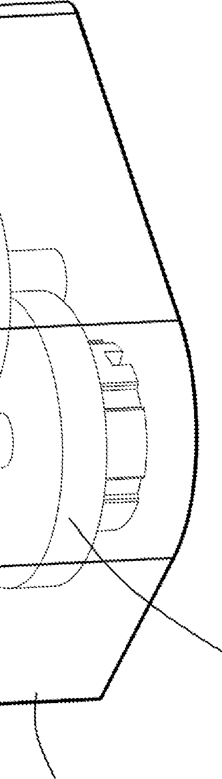
Figure 4 shows a perspective representation of the actuator of Figure 1, with the upper housing portion and gear train omitted for clarity.
Referring to Figures 1 to 3, there is provided an actuator, indicated globally at 10, which is preferably provided as a stepper actuator suitable for use in an automotive context, for example, as part of a heating, ventilation and air conditioning (HVAC) system.
The stepper actuator 10 comprises an electric motor 12 and a gear train 14 which are enclosed within an actuator housing 16. In the present arrangement, at least some of the individual gears of the gear train 14 are oriented such that their footprint overlaps with that of the electric motor 12 when installed into the actuator housing 16.
The electric motor 12 is here formed as a star motor having a central rotor 18 which is received within a rotor receiving portion 20 of a coil body 22 onto which at least one, and preferably a plurality of stator windings 24 is mounted, with the stator 26 being provided as a plurality of stator elements 28 which are engagable with the coil body 22. In the depicted embodiment, the coil body 22 has a plurality of stator engagement members 30 which extend radially from the rotor 18; here, four such stator engagement members 30 are shown. Whilst a stator 26 having multiple stator portions 28 is depicted, it will be appreciated that a motor could be constructed having a unitary stator, which might be achieved by having a multi-part coil body, and therefore the depicted arrangement is for indicative purposes only.
Each stator engagement member 30 comprises a, preferably elongate, member body, which extends radially away from the rotor 18 and terminates at an end cap 32. The end cap 32 extends proud of the member body in a lateral direction, at least in part, so as to define a shoulder relative to an outer surface of the member body. The stator windings 24 can be wound around the outer surface of each stator engagement member 30, the end caps 32 preventing the stator windings 24 from sliding off the outer surface of the stator engagement members 30.
In the depicted embodiment, each of the member bodies is formed from two parallel spaced apart body portions, which, in conjunction with a receiving aperture in the associated end cap 32, defines a stator element receptacle in the member body.
The stator 26 is preferably formed from a plurality of discrete stator elements 28, which are here formed so as to have three conjoined arms: two outer stator arms 34, an end of each outer stator arm 34 preferably being formed so as to match a curvature of the coil body 22 which is adjacent the rotor 18; and a central stator arm 36 which is receivable within the stator element receptacle to retain the stator element 28 in position on its respective stator engagement member 30.
On one of the stator engagement members 30 there may preferably be provided an electrical connector 38, which has a connector body 40 and at least one electricallyconductive element 42 extending therefrom. Here, the electrical connector 38 is formed as a male engagement connector, wherein the electrically-conductive elements 42 are formed as six projecting pins 44 which extend through the connector body 40 into corresponding connector terminals 46. Any appropriate form of electrical connector may be provided, of course, including female engagement connectors.
The electrical connector 38 may preferably be integrally formed with the coil body 22, in this case extending from an end cap 32 of the stator engagement member 30 to which it is attached. The electrical connector 38 is spaced apart from the rotor 18 not only in the plane of the stator engagement members 30, but also in a direction parallel to the rotational axis of the rotor 18. This increases the height of the coil body 24.
That the electrical connector 38 sits proud of the receiving aperture allows the stator element 28 engagable with the corresponding stator engagement member 30 to be engaged therewith without difficulty. The electrical connector 38 may also project beyond the distalmost portion of the end cap 32 in a longitudinal direction of the stator engagement member 30, for example, with the pins 44 projecting outwardly from the end cap 32 to give the coil body 22 an overall elongate cruciform profile, when viewed from above.
The actuator housing 16 is preferably formed as a two-part housing, having first and second, preferably upper and lower, housing portions 48, 50 which are complementarily interengagable. The first housing portion 48 is formed so as to receive the electric motor 12, here having a substantially cruciform body region 52 and a connector access port 54 which, when assembled, is aligned to the electrical connector 38 so as to permit onward electrical connection of the electric motor 12 to, for example, a power supply and/or control electronics.
The second housing portion 50 is here formed having a deep body region 56, within which at least an output gear 58 of the gear train 14 is seatable, the deep body region 56 an access aperture 60 through which the output gear 58 may project. This deep body region 56 may be seated at or adjacent to the connector access port 54 of the first housing portion 48, once assembled, and may have at least one wall 62 of the connector access port 54 formed, preferably integrally so, therein.
The second housing portion 50 may also include a shallow body region 64 which is adjacent to the deep body region 56 and is adapted to receive the electric motor 12. In the depicted embodiment, there is a plurality of elongate members 66 which project out of the shallow body region 64, preferably at or adjacent to a perimeter of the second housing portion 50. The elongate members 66 are preferably integrally formed as part of the second housing portion 50, but could feasibly be releasably engagable with the second housing portion 50, if this would simplify the manufacture and/or assembly of the actuator 10.
The present invention utilises the actuator housing 16 as a direct support for the electric motor 12 and the gear train 14, without requiring the use of a motor-support plate. The insertion of the electric motor 12 into the second housing portion 50 of the actuator housing 16 is shown in Figure 4.
The electric motor 12 is directly mountable onto a plurality of motor supports, preferably by direct contact with the coil body 22 and/or the stator elements 28, such that the motor-support plate can be dispensed with.
In the depicted embodiment, each of the projecting elongate members 66 is aligned so as to contact with the electric motor 12 at or adjacent to the ends of corresponding stator engagement members 30. This may preferably be achieved by the projection of the end caps 32 of the stator engagement members 30 proud of the engaged stator elements 28 to form a lip or shoulder which can rest or engage with a distalmost end of corresponding elongate members 66 to support the electric motor 12 in position.
Furthermore, the electrical connector 38 may also engage with a separate support of the second housing portion 50. In this instance, the connector body 40 of the electrical connector 38 may be seatable on the wall 62 of the connector access port 54, so as to provide a support which is vertically spaced-apart from the corresponding points of contact on the elongate members 66.
To assemble the actuator 10, the gear train 14 can be inserted into the actuator housing
16 so as to be rotationally operable, and there may be pre-formed seats within the actuator housing 16 which define positions for the gears of the gear train 14.
Once the gears have been installed into the actuator housing 16, the electric motor 12, preferably having been preassembled, can be inserted into the actuator housing 16. This can be achieved by seating the electrical connector 38 so as to abut or otherwise engage with the wall 62 of the connector access port 54, and by seating the coil body 22 and/or stator elements 28 onto the elongate members 66, thereby supporting the electric motor 12 directly on the actuator housing 16 at a plurality of different support locations, here there being four such supports. Preferably the supports correspond with the number and positions of the stator engagement members 30.
This assembly is preferably completed in the second housing portion 50 only, which then allows the first housing portion 48 to be receivably engaged with the second housing portion 50 to seal the actuator housing 16, forming a complete and unitary actuator 10. This sealing may be releasable or otherwise; preferably the first and second housing portions 48, 50 will be irreversibly connected, for example using adhesive and/or by welding the two portions to one another.
The actuator 10 formed is therefore a compact unit, having all of the relevant components sealed inside in position, with an electrical input at the connector access port 54 and a drive output at the access aperture 60 for onward connection of drive of the actuator. The actuator 10 is comparatively straightforward to assemble, requiring fewer materials and components in order to complete the assembly than a traditional actuator arrangement.
Whilst the above invention has been described in the context of a star motor, it will be appreciated that the concept could be extended to other forms of motors, if suitable supports in the actuator housing are provided which can abut or otherwise engage with at least part of an electric motor inserted into the actuator housing. For example, a cylindrical motor having a stator with engagement regions could conceivably be provided.
It is also noted that whilst the gear train is described as being installed into the actuator housing prior to the electric motor in the above embodiment, the order of installation could readily be reversed, and this may be dependent upon the construction of the actuator housing.
It is therefore possible to provide an actuator which houses an electric motor and a gear train without the need to provide a separate motor-support or separation plate. This is achieved by providing one or more supports from which the electric motor can be mounted directly to the actuator housing to both reduce the complexity of assembly and the number of components required to produce an actuator.
The words ‘comprises/comprising’ and the words ‘having/including’ when used herein with reference to the present invention are used to specify the presence of stated features, integers, steps or components, but do not preclude the presence or addition of one or more other features, integers, steps, components or groups thereof.
It is appreciated that certain features of the invention, which are, for clarity, described in the context of separate embodiments, may also be provided in combination in a single embodiment. Conversely, various features of the invention which are, for brevity, described in the context of a single embodiment, may also be provided separately or in any suitable sub-combination.
The embodiments described above are provided by way of examples only, and various other modifications will be apparent to persons skilled in the field without departing from the scope of the invention as defined herein.
Claims (19)
1. An actuator comprising:
an electric motor having a coil body having a rotor receiving portion and a plurality of stator engagement members at or adjacent to the rotor receiving portion;
a rotor receivably mountable at the rotor receiving portion;
a stator which is engagable with the plurality of stator engagement members; and at least one stator winding mountable about an outer surface of each of the plurality of stator engagement members; and an actuator housing having a plurality of motor supports which are directly engagable with the coil body and/or stator elements to support the electric motor inside the actuator housing.
2. An actuator as claimed in claim 1, wherein the actuator housing is a two-part enclosure having first and second housing portions, the plurality of motor supports being provided in one or other of the first and second housing portion.
3. An actuator as claimed in claim 1 or claim 2, wherein the plurality of motor supports is integrally formed with the actuator housing.
4. An actuator as claimed in any one of the preceding claims, wherein each of the plurality of stator engagement members comprises a member body which extends from the rotor receiving portion and an end cap at a distal end of the member body, the stator winding being mountable about the member body.
5. An actuator as claimed in claim 4, wherein each end cap is complementarily engagable with a motor support.
6. An actuator as claimed in claim 4 or claim 5, wherein the member body includes a receiving aperture therethrough within which at least part of the stator is receivable.
7. An actuator as claimed in any one of the preceding claims, wherein the plurality of stator engagement members is angularly equi-positioned about the rotor receiving portion.
8. An actuator as claimed in any one of the preceding claims, wherein the stator is provided as a plurality of stator elements which are respectively engagable with the plurality of stator engagement members.
9. An actuator as claimed in any one of the preceding claims, wherein four said stator engagement members are provided, each stator engagement member being engagable with one of the plurality of motor supports.
10. An actuator as claimed in any one of the preceding claims, further comprising an electrical connector engaged with the coil body.
11. An actuator as claimed in claim 10, wherein the electrical connector is spaced apart from the rotor receiving portion along an axis of rotation of the rotor.
12. An actuator as claimed in claim 10 or claim 11, wherein the electrical connector is positioned at a distalmost end of one of the plurality of stator engagement members relative to the rotor receiving portion.
13. An actuator as claimed in claim 12, wherein the electrical connector projects beyond the stator element when engaged with the said stator engagement member.
14. An actuator as claimed in any one of claims 10 to 13, wherein the electrical connector is complementarily engagable with a motor support.
15. An actuator as claimed in any one of the preceding claims, further comprising at least one output gear mountable within the actuator housing.
16. An actuator as claimed in any one of the preceding claims, wherein at least one of the plurality of motor supports is provided as an elongate member extended from an internal surface of the actuator housing.
17. An actuator comprising:
an electric motor having a coil body having a rotor receiving portion and a stator support at or adjacent to the rotor receiving portion;
a rotor receivably mountable at the rotor receiving portion;
a stator which is engagable with the stator support; and at least one stator winding mountable about the coil body;
and an actuator housing having a plurality of motor supports which is directly engagable with the coil body and/or stator to support the electric motor inside the actuator housing.
18. An actuator as claimed in claim 17, further comprising an electrical connector engaged with the coil body, wherein the electrical connector is directly engagable with one of the plurality of motor supports.
19. A method of reducing the size of an actuator without a motor-support plate, the method comprising the steps of:
a] providing an electric motor having a coil body having a rotor receiving portion and a plurality of stator engagement members at or adjacent to the rotor receiving portion; a rotor receivably mountable at the rotor receiving portion; a stator which is engagable with the plurality of stator engagement members; and at least one stator winding respectively mountable about an outer surface of each of the plurality of stator engagement members;
b] inserting at least one output gear into an actuator housing without providing a motor-support plate for the at least one output gear;
c] inserting the electric motor into the actuator housing having a plurality of motor supports such that the coil body directly engages with the plurality of motor supports; and
d] sealing the actuator housing.
Intellectual
Property
Office
Application No: GB1615968.3
Priority Applications (5)
| Application Number | Priority Date | Filing Date | Title |
|---|---|---|---|
| GB1615968.3A GB2553856A (en) | 2016-09-20 | 2016-09-20 | Actuator |
| CN201710852982.0A CN107846101A (en) | 2016-09-20 | 2017-09-19 | Actuator |
| JP2017180020A JP2018078787A (en) | 2016-09-20 | 2017-09-20 | Actuator |
| US15/710,282 US20180080573A1 (en) | 2016-09-20 | 2017-09-20 | Actuator |
| DE102017121767.3A DE102017121767A1 (en) | 2016-09-20 | 2017-09-20 | actuator |
Applications Claiming Priority (1)
| Application Number | Priority Date | Filing Date | Title |
|---|---|---|---|
| GB1615968.3A GB2553856A (en) | 2016-09-20 | 2016-09-20 | Actuator |
Publications (2)
| Publication Number | Publication Date |
|---|---|
| GB201615968D0 GB201615968D0 (en) | 2016-11-02 |
| GB2553856A true GB2553856A (en) | 2018-03-21 |
Family
ID=57288651
Family Applications (1)
| Application Number | Title | Priority Date | Filing Date |
|---|---|---|---|
| GB1615968.3A Withdrawn GB2553856A (en) | 2016-09-20 | 2016-09-20 | Actuator |
Country Status (5)
| Country | Link |
|---|---|
| US (1) | US20180080573A1 (en) |
| JP (1) | JP2018078787A (en) |
| CN (1) | CN107846101A (en) |
| DE (1) | DE102017121767A1 (en) |
| GB (1) | GB2553856A (en) |
Families Citing this family (7)
| Publication number | Priority date | Publication date | Assignee | Title |
|---|---|---|---|---|
| GB2553839A (en) * | 2016-09-16 | 2018-03-21 | Johnson Electric Sa | Electric motor |
| US10141804B2 (en) | 2017-01-11 | 2018-11-27 | Infinitum Electric Inc. | System, method and apparatus for modular axial field rotary energy device |
| FR3100473B1 (en) * | 2019-09-10 | 2021-07-30 | Sidel Participations | Stretching device and winding unit of such a stretching device |
| US11283319B2 (en) | 2019-11-11 | 2022-03-22 | Infinitum Electric, Inc. | Axial field rotary energy device with PCB stator having interleaved PCBS |
| US20210218304A1 (en) | 2020-01-14 | 2021-07-15 | Infinitum Electric, Inc. | Axial field rotary energy device having pcb stator and variable frequency drive |
| DE102020100988A1 (en) * | 2020-01-16 | 2021-07-22 | Ebm-Papst St. Georgen Gmbh & Co. Kg | Assembly with connectors that can be mounted orthogonally to the assembly direction of the assembly |
| US11482908B1 (en) | 2021-04-12 | 2022-10-25 | Infinitum Electric, Inc. | System, method and apparatus for direct liquid-cooled axial flux electric machine with PCB stator |
Citations (4)
| Publication number | Priority date | Publication date | Assignee | Title |
|---|---|---|---|---|
| US20030006656A1 (en) * | 2001-07-03 | 2003-01-09 | Prineppi Frank J. | Display devices |
| EP1437817A1 (en) * | 2003-01-10 | 2004-07-14 | Askoll Holding S.r.l. | Synchronous electric motor with a permanent magnet rotor and improved supporting spools for circulation pumps of heating and air-conditioning systems |
| CN205178745U (en) * | 2015-10-01 | 2016-04-20 | 许煌熙 | Barbecue rotating device using double fixing seats to position motor rotor |
| WO2017010412A1 (en) * | 2015-07-13 | 2017-01-19 | 日本電産サンキョー株式会社 | Motor, motor device, and pointer type display device |
Family Cites Families (11)
| Publication number | Priority date | Publication date | Assignee | Title |
|---|---|---|---|---|
| JPH08322226A (en) * | 1995-03-20 | 1996-12-03 | Asmo Co Ltd | Rotary actuator |
| US6157277A (en) * | 1997-12-09 | 2000-12-05 | Siemens Automotive Corporation | Electromagnetic actuator with improved lamination core-housing connection |
| DE10203709A1 (en) * | 2001-02-02 | 2002-10-02 | Lg Electronics Inc | Process for core lamination in an engine and its lamination construction |
| ES2314169T3 (en) * | 2003-01-10 | 2009-03-16 | Askoll Holding S.R.L. | ELECTRIC MOTOR SYNCHRONOUS PERMANENT MAGNETS FOR PUMPS CIRCULATING HEATING SYSTEMS AND / OR CONDITIONING. |
| KR20060129701A (en) * | 2005-06-13 | 2006-12-18 | 한라공조주식회사 | Door actuator for vehicle air conditioner with bidirectional output shaft |
| JP5583415B2 (en) * | 2009-01-13 | 2014-09-03 | 日本電産サンキョー株式会社 | Motor actuator |
| CN202906621U (en) * | 2009-05-27 | 2013-04-24 | Cts公司 | Actuator assembly and actuator |
| DE102011054956B4 (en) * | 2011-10-31 | 2022-05-12 | Minebea Mitsumi Inc. | Drive unit for an actuator with an electric motor and associated actuator |
| CN104638802B (en) * | 2013-11-15 | 2018-03-06 | 日本电产三协株式会社 | Motor and its manufacture method |
| FR3039337B1 (en) * | 2015-07-23 | 2017-09-01 | Mmt Sa | COMPACT MOTOREDUCER |
| GB2547678A (en) * | 2016-02-25 | 2017-08-30 | Johnson Electric Sa | Method of maintaining a position of an airflow-direction control element of a HVAC system |
-
2016
- 2016-09-20 GB GB1615968.3A patent/GB2553856A/en not_active Withdrawn
-
2017
- 2017-09-19 CN CN201710852982.0A patent/CN107846101A/en active Pending
- 2017-09-20 JP JP2017180020A patent/JP2018078787A/en not_active Abandoned
- 2017-09-20 DE DE102017121767.3A patent/DE102017121767A1/en not_active Withdrawn
- 2017-09-20 US US15/710,282 patent/US20180080573A1/en not_active Abandoned
Patent Citations (4)
| Publication number | Priority date | Publication date | Assignee | Title |
|---|---|---|---|---|
| US20030006656A1 (en) * | 2001-07-03 | 2003-01-09 | Prineppi Frank J. | Display devices |
| EP1437817A1 (en) * | 2003-01-10 | 2004-07-14 | Askoll Holding S.r.l. | Synchronous electric motor with a permanent magnet rotor and improved supporting spools for circulation pumps of heating and air-conditioning systems |
| WO2017010412A1 (en) * | 2015-07-13 | 2017-01-19 | 日本電産サンキョー株式会社 | Motor, motor device, and pointer type display device |
| CN205178745U (en) * | 2015-10-01 | 2016-04-20 | 许煌熙 | Barbecue rotating device using double fixing seats to position motor rotor |
Also Published As
| Publication number | Publication date |
|---|---|
| GB201615968D0 (en) | 2016-11-02 |
| DE102017121767A1 (en) | 2018-03-22 |
| US20180080573A1 (en) | 2018-03-22 |
| JP2018078787A (en) | 2018-05-17 |
| CN107846101A (en) | 2018-03-27 |
Similar Documents
| Publication | Publication Date | Title |
|---|---|---|
| GB2553856A (en) | Actuator | |
| US10063120B2 (en) | Motor and in-vehicle apparatus | |
| CA3001308C (en) | Segmented brushless stator interconnect system | |
| EP2940837A2 (en) | Electric motor-driven compressor having an electrical terminal block assembly | |
| EP3334015B1 (en) | Inverter-integrated motor | |
| US9698645B2 (en) | Electric machine and associated method | |
| CN104821680B (en) | Driving equipment | |
| CN107850201B (en) | Compact electric linear drive for racks, especially hydraulic valves, and method of installation | |
| US10618545B2 (en) | Electric power steering apparatus | |
| JP7373631B2 (en) | mechatronic actuator | |
| US11411457B2 (en) | Electric motor | |
| US9502937B2 (en) | Terminal for stator | |
| JP6073702B2 (en) | Centralized power distribution member of motor | |
| US20220190692A1 (en) | Drive device having a brushless electric motor | |
| CN109642577A (en) | Cluster assembly and motor compressor including the cluster assembly | |
| US11973402B2 (en) | Drive device having a brushless electric motor | |
| JP2019115129A (en) | Electric oil pump and method of manufacturing the same | |
| JP2019112979A (en) | Electric oil pump | |
| US5229674A (en) | Electric motor with connector plug in stator groove | |
| CN110224525A (en) | Motor and its shell | |
| GB2553839A (en) | Electric motor | |
| US11146149B2 (en) | Motor for vehicle transmission pump having a sensor and a magnet separated by a non-magnetic barrier | |
| CN106300711A (en) | Stator, motor, vehicle and manufacture method for motor | |
| CN101197509A (en) | Motor | |
| CN117895676B (en) | Stator core assembly, stator assembly, linear motor, suspension device and vehicle |
Legal Events
| Date | Code | Title | Description |
|---|---|---|---|
| WAP | Application withdrawn, taken to be withdrawn or refused ** after publication under section 16(1) |