FR2736737A1 - DEVICE FOR MANAGING RELATIONS BETWEEN OBJECTS - Google Patents
DEVICE FOR MANAGING RELATIONS BETWEEN OBJECTS Download PDFInfo
- Publication number
- FR2736737A1 FR2736737A1 FR9508435A FR9508435A FR2736737A1 FR 2736737 A1 FR2736737 A1 FR 2736737A1 FR 9508435 A FR9508435 A FR 9508435A FR 9508435 A FR9508435 A FR 9508435A FR 2736737 A1 FR2736737 A1 FR 2736737A1
- Authority
- FR
- France
- Prior art keywords
- objects
- signal
- bus
- relationship
- individual
- Prior art date
- Legal status (The legal status is an assumption and is not a legal conclusion. Google has not performed a legal analysis and makes no representation as to the accuracy of the status listed.)
- Granted
Links
- 230000015654 memory Effects 0.000 claims abstract description 231
- 239000004020 conductor Substances 0.000 claims description 162
- 101100528457 Saccharomyces cerevisiae (strain ATCC 204508 / S288c) RMP1 gene Proteins 0.000 claims description 70
- 101001050487 Homo sapiens IST1 homolog Proteins 0.000 claims description 19
- 102100023423 IST1 homolog Human genes 0.000 claims description 19
- 101100180314 Saccharomyces cerevisiae (strain ATCC 204508 / S288c) IST2 gene Proteins 0.000 claims description 11
- 101100096709 Rattus norvegicus Ssbp1 gene Proteins 0.000 claims description 7
- 241000488913 Olax Species 0.000 claims description 6
- 101100156761 Candida albicans (strain SC5314 / ATCC MYA-2876) WOR2 gene Proteins 0.000 claims description 3
- 101100156762 Candida albicans (strain SC5314 / ATCC MYA-2876) WOR3 gene Proteins 0.000 claims description 3
- 238000001914 filtration Methods 0.000 claims description 2
- 230000001902 propagating effect Effects 0.000 claims description 2
- 108091023242 Internal transcribed spacer Proteins 0.000 claims 1
- 238000001356 surgical procedure Methods 0.000 claims 1
- 238000012546 transfer Methods 0.000 abstract description 3
- 238000010586 diagram Methods 0.000 description 55
- 238000007726 management method Methods 0.000 description 37
- 238000000034 method Methods 0.000 description 21
- 239000000872 buffer Substances 0.000 description 12
- 230000006870 function Effects 0.000 description 9
- 230000002123 temporal effect Effects 0.000 description 9
- 239000011159 matrix material Substances 0.000 description 7
- 230000008901 benefit Effects 0.000 description 5
- 238000000926 separation method Methods 0.000 description 5
- 230000000694 effects Effects 0.000 description 4
- 238000012545 processing Methods 0.000 description 4
- 230000001960 triggered effect Effects 0.000 description 4
- 230000004913 activation Effects 0.000 description 3
- 230000008569 process Effects 0.000 description 3
- 230000003068 static effect Effects 0.000 description 3
- 238000007796 conventional method Methods 0.000 description 2
- 238000010494 dissociation reaction Methods 0.000 description 2
- 230000005593 dissociations Effects 0.000 description 2
- 101100173726 Arabidopsis thaliana OR23 gene Proteins 0.000 description 1
- 101100210350 Candida albicans (strain SC5314 / ATCC MYA-2876) WOR1 gene Proteins 0.000 description 1
- 102100022310 SPRY domain-containing SOCS box protein 3 Human genes 0.000 description 1
- 229920006978 SSBR Polymers 0.000 description 1
- 101100246066 Saccharomyces cerevisiae (strain ATCC 204508 / S288c) PUB1 gene Proteins 0.000 description 1
- 101100361283 Saccharomyces cerevisiae (strain ATCC 204508 / S288c) RPM2 gene Proteins 0.000 description 1
- 101100451671 Saccharomyces cerevisiae (strain ATCC 204508 / S288c) SSA3 gene Proteins 0.000 description 1
- 230000003213 activating effect Effects 0.000 description 1
- 230000005540 biological transmission Effects 0.000 description 1
- 230000008859 change Effects 0.000 description 1
- 238000000354 decomposition reaction Methods 0.000 description 1
- 230000001934 delay Effects 0.000 description 1
- 238000011161 development Methods 0.000 description 1
- 238000003780 insertion Methods 0.000 description 1
- 230000037431 insertion Effects 0.000 description 1
- 230000002028 premature Effects 0.000 description 1
- 230000000135 prohibitive effect Effects 0.000 description 1
- 230000000644 propagated effect Effects 0.000 description 1
- 230000004044 response Effects 0.000 description 1
- 101150050176 rnp1 gene Proteins 0.000 description 1
- 101150059622 rnp3 gene Proteins 0.000 description 1
- 230000008054 signal transmission Effects 0.000 description 1
- 239000007787 solid Substances 0.000 description 1
- 101150012404 spsb3 gene Proteins 0.000 description 1
- 101150049705 ssb3 gene Proteins 0.000 description 1
- 238000012360 testing method Methods 0.000 description 1
- 238000010200 validation analysis Methods 0.000 description 1
Classifications
-
- H—ELECTRICITY
- H04—ELECTRIC COMMUNICATION TECHNIQUE
- H04L—TRANSMISSION OF DIGITAL INFORMATION, e.g. TELEGRAPHIC COMMUNICATION
- H04L12/00—Data switching networks
- H04L12/54—Store-and-forward switching systems
- H04L12/56—Packet switching systems
- H04L12/5601—Transfer mode dependent, e.g. ATM
-
- H—ELECTRICITY
- H04—ELECTRIC COMMUNICATION TECHNIQUE
- H04L—TRANSMISSION OF DIGITAL INFORMATION, e.g. TELEGRAPHIC COMMUNICATION
- H04L49/00—Packet switching elements
- H04L49/10—Packet switching elements characterised by the switching fabric construction
- H04L49/104—Asynchronous transfer mode [ATM] switching fabrics
- H04L49/105—ATM switching elements
- H04L49/106—ATM switching elements using space switching, e.g. crossbar or matrix
-
- H—ELECTRICITY
- H04—ELECTRIC COMMUNICATION TECHNIQUE
- H04L—TRANSMISSION OF DIGITAL INFORMATION, e.g. TELEGRAPHIC COMMUNICATION
- H04L49/00—Packet switching elements
- H04L49/10—Packet switching elements characterised by the switching fabric construction
- H04L49/104—Asynchronous transfer mode [ATM] switching fabrics
- H04L49/105—ATM switching elements
- H04L49/108—ATM switching elements using shared central buffer
-
- H—ELECTRICITY
- H04—ELECTRIC COMMUNICATION TECHNIQUE
- H04L—TRANSMISSION OF DIGITAL INFORMATION, e.g. TELEGRAPHIC COMMUNICATION
- H04L12/00—Data switching networks
- H04L12/54—Store-and-forward switching systems
- H04L12/56—Packet switching systems
- H04L12/5601—Transfer mode dependent, e.g. ATM
- H04L2012/5678—Traffic aspects, e.g. arbitration, load balancing, smoothing, buffer management
-
- Y—GENERAL TAGGING OF NEW TECHNOLOGICAL DEVELOPMENTS; GENERAL TAGGING OF CROSS-SECTIONAL TECHNOLOGIES SPANNING OVER SEVERAL SECTIONS OF THE IPC; TECHNICAL SUBJECTS COVERED BY FORMER USPC CROSS-REFERENCE ART COLLECTIONS [XRACs] AND DIGESTS
- Y10—TECHNICAL SUBJECTS COVERED BY FORMER USPC
- Y10S—TECHNICAL SUBJECTS COVERED BY FORMER USPC CROSS-REFERENCE ART COLLECTIONS [XRACs] AND DIGESTS
- Y10S707/00—Data processing: database and file management or data structures
- Y10S707/99941—Database schema or data structure
- Y10S707/99942—Manipulating data structure, e.g. compression, compaction, compilation
Landscapes
- Engineering & Computer Science (AREA)
- Computer Networks & Wireless Communication (AREA)
- Signal Processing (AREA)
- Physics & Mathematics (AREA)
- Mathematical Physics (AREA)
- Bus Control (AREA)
- Data Exchanges In Wide-Area Networks (AREA)
- Hardware Redundancy (AREA)
- Exchange Systems With Centralized Control (AREA)
- Crystals, And After-Treatments Of Crystals (AREA)
- Container, Conveyance, Adherence, Positioning, Of Wafer (AREA)
- Information Retrieval, Db Structures And Fs Structures Therefor (AREA)
Abstract
Description
Dispositif de gestion de relations entre des obiets.Device for managing relations between objects.
L'invention concerne un dispositif de gestion de relations entre des objets identifiables individuellement dans un champ d'adressage fini, plus particulièrement pour des applications en temps réel. Chaque relation associe deux objets appartenant à un même ensemble d'objets, ou appartenant respectivement à deux ensembles contenant des objets de même type ou de types différents. Le terme relation doit être entendu au sens large, car il peut changer en fonction des applications considérées. D'autre part un même objet peut être associé à un ou plusieurs autres objets par plusieurs relations de natures différentes. The invention relates to a device for managing relations between individually identifiable objects in a finite addressing field, more particularly for real-time applications. Each relation associates two objects belonging to the same set of objects, or belonging respectively to two sets containing objects of the same type or of different types. The term relation must be understood in the broad sense, because it can change according to the applications considered. On the other hand, the same object can be associated with one or more other objects by several relations of different natures.
Une application particulièrement importante se situe dans le domaine des télécommunications, et plus particulièrement dans le domaine de la gestion des relations entre cellules transférées en mode asynchrone. En effet, un système de commutation à mode de transfert asynchrone comporte une ou plusieurs mémoires tampons pour stocker temporairement des cellules à commuter. Cette mémoire tampon est généralement utilisée comme une file d'attente, par exemple du type premier-entré-premier-sorti. Dans ce premier exemple d'application, il est nécessaire de gérer des relations d'ordre entre les différents emplacements de cette mémoire tampon pour indiquer l'ordre respectif des cellules d'une file d'attente qui sont stockées dans ces emplacements. A particularly important application is in the field of telecommunications, and more particularly in the field of management of relationships between cells transferred in asynchronous mode. Indeed, an asynchronous transfer mode switching system comprises one or more buffers for temporarily storing cells to be switched. This buffer is generally used as a queue, for example of the first-in-first-out type. In this first application example, it is necessary to manage order relationships between the different locations of this buffer to indicate the respective order of the cells of a queue that are stored in these locations.
Dans cette application, la relation est du type "cellule suivante dans la file d'attente" et associe une cellule qui est située dans un certain emplacement de la mémoire tampon à une autre cellule "suivanten qui est située dans un autre emplacement de la mémoire tampon. En général, dans le cas de mémoire tampon partagée pour plusieurs files d'attente, cet emplacement n'est pas un emplacement voisin car les emplacements sont libérés dans un ordre qui est aléatoire et sont réutilisés au fur et à mesure de leur libération. In this application, the relationship is of type "next cell in queue" and associates a cell that is located in a certain buffer location with another "next" cell that is located in another memory location In general, in the case of a shared buffer for multiple queues, this location is not a neighboring location because the slots are released in an order that is random and are reused as they are released. .
Classiquement, la gestion de l'ordre respectif des cellules d'une file d'attente est réalisée en gérant des identificateurs de cellules, tels que les adresses des emplacements de mémoire contenant ces cellules. Par exemple, pour mémoriser l'ordre des cellules d'une file d'attente, qui sont stockées dans une mémoire tampon, leurs adresses sont inscrites à des adresses successives dans une mémoire dite d'adresses, adressée en écriture par un pointeur d'écriture incrémenté d'une unité après chaque écriture, et adressée en lecture par un pointeur de lecture, incrémenté d'une unité après chaque lecture. L'ordre dans lequel les adresses ont été inscrites dans les lignes consécutives de cette mémoire détermine l'ordre dans lequel les cellules seront relues dans la mémoire tampon. Conventionally, the management of the respective order of the cells of a queue is carried out by managing cell identifiers, such as the addresses of the memory locations containing these cells. For example, to memorize the order of the cells of a queue, which are stored in a buffer memory, their addresses are written to successive addresses in a memory called addresses, addressed in writing by a pointer of incremented write of a unit after each write, and read addressed by a read pointer, incremented by one after each read. The order in which the addresses have been written in the consecutive lines of this memory determines the order in which the cells will be read back into the buffer.
Un autre procédé classique pour gérer l'ordre des cellules d'une file d'attente consiste à constituer une liste d'adresses chainées dans une mémoire à accès aléatoire, dite mémoire de liens. Les emplacements de cette mémoire de liens correspondent respectivement aux emplacements de la mémoire tampon. Chaque emplacement de la mémoire de liens contient une adresse qui est la prochaine adresse à utiliser, d'une part pour lire la cellule suivante dans la mémoire tampon, et d'autre part pour lire une prochaine adresse à utiliser dans cette mémoire de liens. Un tel procédé de gestion d'ordre entre cellules est décrit par exemple dans la demande de brevet européen n O.441.787 (Henrion 18). Another conventional method for managing the order of the cells of a queue is to form a list of addresses chained in a random access memory, called link memory. The locations of this link memory correspond respectively to the locations of the buffer memory. Each location of the link memory contains an address which is the next address to use, firstly to read the next cell in the buffer, and secondly to read a next address to use in this link memory. Such a method of order management between cells is described for example in European Patent Application No. 4,441,787 (Henrion 18).
Dans ces deux exemples classiques de gestion d'ordre entre cellules d'une file d'attente, les identificateurs explicites utilisés sont les adresses de cellules, tandis que les relations entre cellules restent implicites. In these two classic examples of order management between cells of a queue, the explicit identifiers used are the cell addresses, while the relationships between cells remain implicit.
I1 existe un autre type de relation qui ne définit pas un ordre particulier ou une classification particulière des objets, mais plutôt l'appartenance à un même sous-ensemble ou groupement d d'objets, obj ets , tous les objets du sous-ensemble considéré ayant strictement les mêmes caractéristiques visà-vis de cette relation. Dans le domaine des télécommunications, on trouve un exemple d'une telle relation entre des cellules qui doivent être restituées par une mémoire tampon pendant un même intervalle temporel, dans le but de reséquencer les cellules dans un ordre correspondant à leur ordre d'arrivée.Lorsqu'une cellule arrive dans le système de commutation considéré, celui-ci lui associe une étiquette temporelle indiquant l'intervalle temporel au cours duquel cette cellule doit être restituée sur l'une des sorties du système de commutation. Toutes les cellules qui sont associées à une même étiquette temporelle sont alors associées à cette étiquette temporelle par une relation particulière, du type appartenance à un sousensemble, sans qu'il y ait pour autant une relation d'ordre entre les différentes cellules appartenant à cet ensemble. There is another type of relation which does not define a particular order or classification of objects, but rather the belonging to the same subset or grouping of objects, objects, all the objects of the subset considered. having strictly the same characteristics vis-à-vis this relation. In the field of telecommunications, there is an example of such a relationship between cells that must be restored by a buffer memory during the same time interval, in order to resequencing the cells in an order corresponding to their order of arrival. When a cell arrives in the switching system considered, it associates with it a time label indicating the time interval during which this cell must be restored on one of the outputs of the switching system. All the cells that are associated with the same time tag are then associated with this time tag by a particular relation, of the subset unit type, without there being any order relationship between the different cells belonging to this subset. together.
Un tel procédé de reséquencement de cellules est décrit par exemple dans la demande de brevet européen ne0.438.415 (Henrion 17).Such a cell resequencing method is described, for example, in European Patent Application No. 0438,415 (Henrion 17).
Pour gérer de tels groupements dans un ensemble d'objets non ordonnés, on utilise classiquement
- une mémoire d'attente où les cellules séjournent suffisamment longtemps pour que les cellules retardataires rejoignent les autres ayant une même étiquette temporelle;
- et une pile où sont transférées toutes les cellules ayant cette étiquette, sans ordre particulier entre elles, sauf celui des étiquettes temporelles de chaque sousensemble de cellules.To manage such groupings in a set of non-ordered objects, we use conventionally
a waiting memory where the cells stay long enough for the lagging cells to join the others having the same time tag;
and a stack in which all the cells having this label are transferred, in no particular order between them, except that of the time tags of each subset of cells.
Des procédés connus de gestion de relations entre des objets, dans des ensembles d'objets ordonnés ou non ordonnés, sont classiquement mis en oeuvre au moyen de mémoires conventionnelles à accès aléatoire ou de mémoires adressables par leur contenu. La mise en oeuvre de ces procédés connus revient toujours à mémoriser des identificateurs d'objets, et non des identificateurs de relations entre objets.C'est donc la façon de mémoriser les identificateurs d'objets, par exemple en fonction de leur ordre dans une file d'attente qui détermine implicitement les relations d'ordre entre les objets. I1 en résulte que les dispositifs classiques de gestion d'objets par relations implicites ont les limitations suivantes
- Le temps d'exécution des opérations de gestion devient prohibitif s'il est nécessaire de gérer plusieurs relations au cours d'une même opération; par exemple, pour retrouver et réarranger des relations lorsqu'un objet doit être ajouté ou doit être retiré à un ensemble donné.Known methods for managing relations between objects, in sets of ordered or non-ordered objects, are conventionally implemented by means of conventional random access memories or memories addressable by their contents. The implementation of these known methods always amounts to memorizing object identifiers, and not identifiers of relations between objects. It is therefore the way of memorizing the object identifiers, for example according to their order in an object. Queue that implicitly determines the order relationships between objects. As a result, conventional implicit relationship object management devices have the following limitations:
- The execution time of the management operations becomes prohibitive if it is necessary to manage several relations during the same operation; for example, to find and rearrange relationships when an object needs to be added or removed to a given set.
- La réalisation d'un dispositif de gestion pour plusieurs relations est extrêmement complexe parce que la gestion des relations implicites est distribuée dans plusieurs mémoires distinctes contenant les identificateurs d'objets dans le but d'épargner du temps en parallélisant les opérations. La complexité augmente rapidement avec le nombre de mémoires et avec le nombre de chemins parallèles nécessaires pour interconnecter les différents accès à ces mémoires : conducteurs de sélection d'un élément de mémoire, conducteurs de commande d'écriture, et conducteurs de commande de lecture. - The realization of a management device for several relationships is extremely complex because the management of implicit relations is distributed in several separate memories containing the object identifiers in order to save time by parallelizing the operations. The complexity increases rapidly with the number of memories and with the number of parallel paths necessary to interconnect the different accesses to these memories: memory element selection conductors, write control conductors, and read control conductors.
Le but de l'invention est de proposer un dispositif de gestion de relations entre des objets, satisfaisant mieux les contraintes du temps réel, et permettant d'envisager alors des opérations de gestion plus complexes que celles réalisées jusqu'à présent (exécution parallèle et/ou combinée de plusieurs opérations élémentaires), impliquant un ou plusieurs types de relation à l'intérieur d'un même ensemble d'objets ou d'une structure comprenant plusieurs ensembles d'objets. The object of the invention is to propose a device for managing relations between objects, better satisfying the constraints of real time, and making it possible to envisage management operations that are more complex than those carried out so far (parallel execution and / or combined of several elementary operations), involving one or more types of relationship within the same set of objects or a structure comprising several sets of objects.
Par exemple, dans le domaine des systèmes de commutation à mode de transfert asynchrone, il peut être intéressant de gérer, dans un ensemble ordonné de cellules, plusieurs relations indiquant respectivement : la cellule suivante, la cellule précédente, la première cellule d'une liste ordonnée, et la dernière cellule d'une liste ordonnée. For example, in the field of asynchronous transfer mode switching systems, it may be interesting to manage, in an ordered set of cells, several relationships indicating respectively: the next cell, the previous cell, the first cell of a list ordered, and the last cell of an ordered list.
Dans un sous-ensemble non ordqnné de cellules, il peut être intéressant de gérer des relations entre une cellule et chacune des autres cellules, ou bien entre chaque cellule et une cellule considérée comme référence pour le sous-ensemble considéré. La gestion de telles relations d'appartenance permet de grouper les cellules en différents niveaux de priorité pour la perte de cellules et/ou les retards à appliquer à chaque cellule ; en groupes de reséquencement des cellules; en files d'attente de sortie; etc.In an unordered subset of cells, it may be interesting to manage relations between a cell and each of the other cells, or between each cell and a cell considered as reference for the subset considered. The management of such membership relationships makes it possible to group the cells into different priority levels for the loss of cells and / or the delays to be applied to each cell; in groups of resequencing of the cells; in output queues; etc.
L'objet de l'invention est un dispositif de gestion de relations entre des objets identifiables individuellement dans un champ d'adressage fini,
caractérisé en ce que, pour tout couple de deux objets distincts, appelés premier objet et second objet, et pour chaque relation susceptible d'associer ces deux objets, il comporte un élément de mémoire dit de relation pour mémoriser une information dite de relation indiquant soit l'existence, soit l'inexistence, de cette relation;;
en ce que ces éléments de mémoire de relation sont structurés en un réseau à au moins deux dimensions, à l'aide d'une pluralité de bus susceptibles d'acheminer des signaux de sélection d'objet et des signaux de commande d'opération, chaque élément étant situé au point d'intersection de deux bus dits individuels, chaque bus individuel correspondant respectivement à un objet et étant susceptible de transporter au moins un signal dit de sélection de cet objet;
en ce que chaque élément comporte un circuit logique pouvant recevoir au moins un signal de sélection et pouvant recevoir au moins un signal de commande d'opération, pour écrire ou lire une information de relation dans cet élément;;
et en ce qu'il comporte des moyens logiques couplés à des points d'accès des bus, pour leur fournir des signaux de commande d'opération, pour leur fournir des signaux de sélection d'objet, et pour recevoir d'eux des informations lues dans les éléments de mémoire de relation.The object of the invention is a device for managing relations between individually identifiable objects in a finite addressing field,
characterized in that, for any pair of two distinct objects, called first object and second object, and for each relationship likely to associate these two objects, it comprises a so-called relationship memory element for storing a so-called relationship information indicating either the existence, or nonexistence, of this relationship;
in that said relationship memory elements are structured into an at least two-dimensional network, using a plurality of buses capable of conveying object selection signals and operation control signals, each element being situated at the intersection point of two so-called individual buses, each individual bus respectively corresponding to an object and being capable of carrying at least one so-called selection signal of this object;
in that each element comprises a logic circuit capable of receiving at least one selection signal and capable of receiving at least one operation control signal, for writing or reading relationship information in that element;
and in that it comprises logic means coupled to bus access points, for providing them with operation control signals, for providing them with object selection signals, and for receiving information from them read in the relationship memory elements.
et en ce qu'il comporte des moyens logiques couplés à des points d'accès des bus, pour leur fournir au moins des signaux de commande d'opération et des signaux de sélection d'objet; et pour recevoir des informations lues dans les éléments de mémoire de relation. and in that it includes logic means coupled to bus access points, for providing them at least operation control signals and object selection signals; and to receive information read from the relationship memory elements.
Le dispositif ainsi caractérisé gère directement, c'est-à-dire explicitement des relations entre deux objets, au lieu de les gérer indirectement, puisque chaque élément de mémoire permet de mémoriser ou de restituer l'existence ou l'inexistence d'une relation entre deux objets par un adressage direct, par activation des bus individuels correspondant aux objets. The device thus characterized directly manages, that is to say explicitly, relations between two objects, instead of managing them indirectly, since each memory element makes it possible to memorize or to restore the existence or non-existence of a relationship. between two objects by direct addressing, by activating the individual buses corresponding to the objects.
Le dispositif ainsi caractérisé procure une vitesse de traitement plus rapide que les dispositifs selon l'art antérieur, car il permet d'accèder directement aux informations de relation par un réseau de bus. Cette structure en réseau réparti permet un accès très rapide à chaque élément de mémoire correspondant à une relation entre deux objets. D'autre part, l'activation en lecture d'un bus individuel correspondant à un objet donné, permet d'accèder en une seule opération à tous les éléments de mémoire mémorisant les relations établies entre cet objet et d'autres objets de l'ensemble. Une seule opération de lecture permet donc de connaître simultanément toutes ces relations. Le temps nécessaire est donc très court. De même, une seule opération d'écriture permet de mémoriser simultanément l'existence, ou l'inexistence, de plusieurs relations. The device thus characterized provides a faster processing speed than the devices according to the prior art, because it allows direct access to the relationship information via a bus network. This distributed network structure allows very fast access to each memory element corresponding to a relationship between two objects. On the other hand, the read activation of an individual bus corresponding to a given object makes it possible to access in a single operation all memory elements that memorize the relations established between this object and other objects of the object. together. A single read operation therefore makes it possible to know all these relationships simultaneously. The time needed is therefore very short. Similarly, a single write operation makes it possible to simultaneously memorize the existence, or nonexistence, of several relationships.
Un mode de réalisation préférentiel du dispositif selon l'invention pour gérer des relations non nécessairement symétriques entre deux objets distincts dans un ensemble d'objets comportant N objets, est caractérisé en ce que les bus individuels comportent
- N bus de commande de colonne, correspondant respectivement aux N objets, et commandant respectivement N colonnes d'éléments;
- N bus de commande de ligne, correspondant aux N objets, et commandant respectivement N lignes d'éléments; chaque bus de commande de ligne ayant un point d'intersection avec chaque bus de commande de colonne;
et en ce que ce dispositif de gestion de relations comporte N.(N-1) éléments de mémoire pour chaque relation susceptible de relier deux objets distincts parmi N; ces éléments étant situés en des points d'intersection des bus de commande de colonne et des bus de commande de ligne, à l'exception des points d'intersection situés sur une diagonale du réseau.A preferred embodiment of the device according to the invention for managing relations that are not necessarily symmetrical between two distinct objects in a set of objects comprising N objects, is characterized in that the individual buses comprise
- N column control bus, respectively corresponding to the N objects, and respectively controlling N columns of elements;
- N line control bus, corresponding to the N objects, and respectively controlling N rows of elements; each line control bus having a point of intersection with each column control bus;
and in that said relationship management device comprises N. (N-1) memory elements for each relation capable of connecting two distinct objects among N; these elements being located at points of intersection of the column control buses and line control buses, with the exception of intersection points located on a diagonal of the network.
Un autre mode de réalisation préférentiel du dispositif selon l'invention, pour gérer des relations symétriques dans un ensemble de N objets, est caractérisé en ce qu'il comporte N bus individuels correspondant respectivement aux N objets, chaque bus comportant une première et une seconde branche ayant une extrémité commune; et chaque bus ayant un point d'intersection avec chacun des autres bus parmi ces N bus;
en ce que ce dispositif de gestion de relation
N.(N-1) comporte des éléments de mémoire de relation, pour
2 chaque relation symétrique susceptible d'associer deux objets distincts dans cet ensemble de N objets;
en ce que les éléments de mémoire mémorisant les informations de relation entre l'objet de rang i=1 à K-1, et les objets de rang K, pour K choisi entre 1 et N, sont situés en des points d'intersection de la première branche du bus individuel correspondant à cet objet de rang K, et de la seconde branche de chaque bus individuel correspondant respectivement aux objets de rang i= 1 à K-1;;
et en ce que les éléments de mémoire mémorisant des informations de relation entre l'objet de rang K et les objets de rang j=K+1 à N sont situés en des points d'intersection de la seconde branche du bus individuel correspondant à cet objet de rang K, et de la première branche de chaque bus individuel correspondant respectivement aux objets de rang j=K+1 à N.Another preferred embodiment of the device according to the invention, for managing symmetrical relations in a set of N objects, is characterized in that it comprises N individual buses corresponding respectively to the N objects, each bus comprising a first and a second branch having a common end; and each bus having a point of intersection with each of the other buses among these N buses;
in that this relationship management device
N. (N-1) has relationship memory elements, for
2 each symmetrical relation capable of associating two distinct objects in this set of N objects;
in that the memory elements storing the relationship information between the object of rank i = 1 to K-1, and the objects of rank K, for K selected between 1 and N, are located at points of intersection of the first branch of the individual bus corresponding to this object of rank K, and the second branch of each individual bus respectively corresponding to objects of rank i = 1 to K-1 ;;
and in that the memory elements storing information of relationship between the object of rank K and the objects of rank j = K + 1 to N are located at points of intersection of the second branch of the individual bus corresponding to this object of rank K, and of the first branch of each individual bus respectively corresponding to objects of rank j = K + 1 to N.
Ce mode de réalisation présente l'avantage d'être particulièrement simple puisqu'il permet de gérer à partir de N points d'accès des relations symétriques entre N
N2-N objets, avec éléments de mémoire seulement. I1 est
2 utilisable pour la plupart des relations car elles sont généralement symétriques. Par exemple, si une cellule A est placée avant une cellule B, il est évident que la cellule B est placée après la cellule A lorsque l'on exploite la séquence des cellules dans un ordre connu. I1 n'est alors pas nécessaire de mémoriser ces deux relations redondantes.This embodiment has the advantage of being particularly simple since it makes it possible to manage from N access points symmetrical relations between N
N2-N objects, with memory elements only. I1 is
2 usable for most relationships because they are usually symmetrical. For example, if a cell A is placed before a cell B, it is obvious that cell B is placed after cell A when the sequence of cells is exploited in a known order. It is not necessary to memorize these two redundant relationships.
Dans certains modes de réalisation particuliers, cette structure permet en outre d'accéder simultanément aux relations entre un premier et un second sous-ensemble de l'ensemble des éléments de mémoire, sans accéder simultanément aux relations entre objets d'un même sousensemble. L'accès est alors à la fois rapide et sélectif. In certain particular embodiments, this structure also makes it possible to simultaneously access the relations between a first and a second subset of the set of memory elements, without simultaneously accessing the relationships between objects of the same subset. Access is then both fast and selective.
L'invention sera mieux comprise et d'autres caractéristiques apparaitront à l'aide de la description cidessous, d'exemples de réalisation, et des figures l'accompagnant
- les figures 1 à 4 représentent les schémas synoptiques de quatre exemples de réalisation du dispositif selon 1 'invention;
- la figure 5 représente le schéma synoptique d'un premier exemple de réalisation d'un élément de mémoire de relation pour le dispositif selon l'invention;
- la figure 6 représente un bus dit orthogonal et un point d'accès correspondant à un objet donné, pour commander l'exemple de réalisation représenté sur la figure 5;
- la figure 7 représente le schéma synoptique d'une variante du premier exemple de réalisation représenté sur la figure 5;;
- la figure 8 illustre le fonctionnement d'un dispositif de gestion comportant des éléments de mémoire tels que celui représenté sur la figure 5, lors d'une opération de lecture de relations entre objets de deux sous-ensembles A et B (cas de lecture à partir de A);
- la figure 9 représente le schéma synoptique d'un exemple de réalisation d'un dispositif selon l'invention comportant des éléments de mémoire tel que celui représenté sur la figure 5, et illustre son fonctionnement lorsqu'une opération est réalisée sur les relations reliant les objets d'un sous-ensemble S d'un ensemble d'objets;
- la figure 10 illustre le problème qui se pose lorsqu'une opération d'écriture concerne deux sous-ensembles d'objets (S1 et S2);
- la figure 11 représente le schéma synoptique d'un second exemple de réalisation d'un élément de mémoire de relation pour le dispositif selon l'invention;;
- la figure 12 représente un bus dit orthogonal et un point d'accès correspondant à un objet donné, pour commander l'exemple de réalisation représenté sur la figure 10;
- la figure 13 illustre le fonctionnement d'un dispositif de gestion comportant des éléments de mémoire tels que celui représenté sur la figure 10, lors de la lecture de toutes les relations existant entre un objet unique et tous les autres objets de l'ensemble considéré;
- les figures 14 et 15 illustrent deux variantes de fonctionnement de ce même dispositif lors de deux variantes d'une même opération d'écriture réalisée sur les relations reliant les objets d'un sous-ensemble S1 et les objets d'un sous-ensemble S2 (S1 et s2 étant disjoints), à l'exception de toutes les relations entre les objets d'un même sousensemble;;
- les figures 16 et 17 représentent le schéma synoptique d'une variante de réalisation du dispositif selon l'invention, comportant des éléments de mémoire tels que celui représenté sur la figure 5, et illustre son fonctionnement lorsqu'une opération d'écriture est réalisée sur les relations reliant les objets d'un sous-ensemble S1 et les objets d'un sous-ensemble S2, S1 et S2 étant disjoints;
- la figure 18 illustre une autre application d'un dispositif de gestion comportant des éléments de mémoire tels que celui représenté sur la figure 11, lors d'une opération d'écriture de relations entre objets de deux sousensembles S1 et S2 quelconques et non disjoints;
- la figure 19 représente le schéma synoptique d'une variante du second exemple de réalisation représenté sur la figure 11;;
- les figures 20 à 22 illustrent l'application du dispositif selon l'invention à la gestion des relations entre plusieurs sous-ensembles statiques d'objets, rassemblant respectivement des objets appartenant à des catégories différentes;
- les figures 23 à 26 représentent quatre structures élémentaires de relations permettant de gérer les objets d'un sous-ensemble dynamique;
- la figure 27 illustre l'opération de lecture des relations existant entre un objet donné et les objets appartenant à trois sous-ensembles distincts;
- les figures 28 et 30 illustrent une opération d'écriture concernant des relations entre des objets appartenant à deux groupes;
- les figures 30 et 31 illustrent une première opération complexe consistant à libérer toute relation existant entre un objet et tout autre objet;;
- la figure 32 représente le schéma synoptique d'une variante du premier exemple de réalisation d'un élément de mémoire de relation, cette variante permettant de réaliser cette première opération complexe;
- la figure 33 représente le schéma synoptique d'une variante du second exemple de réalisation, cette variante permettant de réaliser cette première opération complexe;
- les figures 34 et 35 illustrent une deuxième opération complexe consistant en une double lecture simultanée de toutes les relations existant entre deux objets donnés et des objets, avec sortie séparée en deux groupes pour les objets identifiés par les deux lectures;
- la figure 36 représente le schéma synoptique d'une variante du premier exemple de réalisation, cette variante permettant de réaliser la deuxième opération complexe;;
- la figure 37 représente le schéma synoptique d'une variante du second exemple de réalisation, cette variante permettant de réaliser la deuxième opération complexe;
- la figure 38 illustre une troisième opération complexe consistant en une lecture par propagation;
- la figure 39 représente le schéma synoptique d'une variante de réalisation du point d'accès représenté sur la figure 6, cette variante comportant des moyens logiques supplémentaires pour réaliser la troisième opération complexe;
- la figure 40 représente le schéma synoptique d'une variante de réalisation du point d'accès représenté sur la figure 12, cette variante comportant des moyens logiques supplémentaires pour réaliser la troisième opération complexe;
- la figure 41 illustre une quatrième opération complexe consistant à libérer des relations par propagation;;
- la figure 42 représente le schéma synoptique d'une variante de réalisation du point d'accès représenté sur la figure 6, cette variante permettant de réaliser la quatrième opération complexe;
- la figure 43 représente un chronogramme illustrant le fonctionnement de cette variante;
- la figure 44 représente le schéma synoptique d'une variante de réalisation du point d'accès représenté sur la figure 12, cette variante comportant des moyens supplémentaires permettant l'exécution de la quatrième opération complexe;
- la figure 45 représente un chronogramme illustrant la réalisation de la quatrième opération complexe;
- la figure 46 illustre une cinquième opération complexe consistant à libérer une relation entre deux objets et à insérer un nouvel objet entre ces deux objets en établissant deux nouvelles relations; ;
- la figure 47 illustre la mise en oeuvre de cette cinquième opération complexe;
- les figures 48 et 49 représentent les schémas synoptiques de deux variantes du premier exemple de réalisation, ces variantes comportant des moyens logiques supplémentaires pour permettre de réaliser la cinquième opération complexe;
- les figures 50 et 51 représentent les schémas synoptiques de deux variantes du second exemple de réalisation, ces variantes comportant des moyens logiques supplémentaires pour permettre de réaliser la cinquième opération complexe;
- la figure 52 illustre une sixième opération complexe consistant à éliminer un objet E connu, dans une chaine linéaire d'objets reliés par des relations sans connaître ses objets adjacents, et à établir automatiquement une relation directe entre les deux objets adjacents éventuels qui encadraient l'objet éliminé;;
- la figure 53 représente le schéma synoptique d'une variante du premier exemple de réalisation, cette variante comportant des moyens logiques supplémentaires par rapport à la variante représentée sur la figure 30, pour permettre la réalisation de la sixième opération complexe;
- la figure 54 représente un chronogramme illustrant le fonctionnement de cette variante;
- la figure 55 représente le schéma synoptique d'une variante de réalisation du point d'accès représenté sur la figure 12, cette variante comportant des moyens logiques supplémentaires pour permettre la réalisation de la sixième opération complexe;;
- la figure 56 représente le schéma synoptique d'un troisième exemple de réalisation d'un élément de mémoire de relation, pour le dispositif selon l'invention cette variante comportant des moyens logiques supplémentaires permettant de réaliser la première opération complexe et la sixième opération complexe, c'est-à-dire une libération de toutes les relations existant entre un objet donné et tout autre objet, puis l'établissement automatique de liaisons entre des objets qui étaient précédemment reliés indirectement par cet objet donné;
- la figure 57 représente un chronogramme illustrant le fonctionnement de cette variante pour réaliser la sixième opération complexe;
- les figures 58 et 59 représentent respectivement des variantes du premier et du second exemple de réalisation.The invention will be better understood and other characteristics will appear with the help of the description below, examples of embodiments, and accompanying figures.
- Figures 1 to 4 show the block diagrams of four embodiments of the device according to the invention;
FIG. 5 represents the block diagram of a first exemplary embodiment of a relationship memory element for the device according to the invention;
FIG. 6 represents an orthogonal bus and an access point corresponding to a given object, for controlling the exemplary embodiment shown in FIG. 5;
FIG. 7 represents the block diagram of a variant of the first embodiment shown in FIG. 5;
FIG. 8 illustrates the operation of a management device comprising memory elements such as that represented in FIG. 5, during an operation of reading relations between objects of two subsets A and B (reading case) from A);
FIG. 9 represents the block diagram of an embodiment of a device according to the invention comprising memory elements such as that represented in FIG. 5, and illustrates its operation when an operation is performed on the relations linking the objects of a subset S of a set of objects;
FIG. 10 illustrates the problem that arises when a write operation concerns two subsets of objects (S1 and S2);
FIG. 11 represents the block diagram of a second exemplary embodiment of a relationship memory element for the device according to the invention;
FIG. 12 represents an orthogonal bus and an access point corresponding to a given object, for controlling the exemplary embodiment shown in FIG. 10;
FIG. 13 illustrates the operation of a management device comprising memory elements such as that represented in FIG. 10, when reading all the relations existing between a single object and all the other objects of the set considered. ;
FIGS. 14 and 15 illustrate two variants of operation of this same device in two variants of the same write operation performed on the relationships connecting the objects of a subset S1 and the objects of a subset S2 (S1 and s2 being disjoint), with the exception of all the relations between the objects of the same subassembly;
FIGS. 16 and 17 show the block diagram of an alternative embodiment of the device according to the invention, comprising memory elements such as that represented in FIG. 5, and illustrates its operation when a write operation is performed on the relations connecting the objects of a subset S1 and the objects of a subset S2, S1 and S2 being disjoint;
FIG. 18 illustrates another application of a management device comprising memory elements such as that represented in FIG. 11, during an operation of writing relations between objects of two subsets S1 and S2, which are non-disjoint ;
FIG. 19 represents the block diagram of a variant of the second exemplary embodiment shown in FIG. 11;
FIGS. 20 to 22 illustrate the application of the device according to the invention to the management of relations between several static subsets of objects, respectively gathering objects belonging to different categories;
FIGS. 23 to 26 represent four elementary relations structures for managing the objects of a dynamic subset;
FIG. 27 illustrates the operation of reading the relations existing between a given object and the objects belonging to three distinct subsets;
FIGS. 28 and 30 illustrate a write operation concerning relationships between objects belonging to two groups;
FIGS. 30 and 31 illustrate a first complex operation of releasing any existing relationship between an object and any other object;
FIG. 32 represents the block diagram of a variant of the first exemplary embodiment of a relationship memory element, this variant making it possible to carry out this first complex operation;
FIG. 33 represents the block diagram of a variant of the second exemplary embodiment, this variant making it possible to carry out this first complex operation;
FIGS. 34 and 35 illustrate a second complex operation consisting of a double simultaneous reading of all the relations existing between two given objects and objects, with separate output in two groups for the objects identified by the two readings;
FIG. 36 represents the block diagram of a variant of the first exemplary embodiment, this variant making it possible to carry out the second complex operation;
FIG. 37 represents the block diagram of a variant of the second exemplary embodiment, this variant making it possible to carry out the second complex operation;
FIG. 38 illustrates a third complex operation consisting of a propagation read;
FIG. 39 represents the block diagram of an alternative embodiment of the access point represented in FIG. 6, this variant comprising additional logic means for carrying out the third complex operation;
FIG. 40 represents the block diagram of an alternative embodiment of the access point shown in FIG. 12, this variant comprising additional logic means for carrying out the third complex operation;
FIG. 41 illustrates a fourth complex operation of releasing propagation relationships;
FIG. 42 represents the block diagram of an alternative embodiment of the access point represented in FIG. 6, this variant making it possible to carry out the fourth complex operation;
- Figure 43 shows a timing diagram illustrating the operation of this variant;
FIG. 44 represents the block diagram of an alternative embodiment of the access point represented in FIG. 12, this variant comprising additional means allowing the execution of the fourth complex operation;
FIG. 45 represents a timing diagram illustrating the carrying out of the fourth complex operation;
FIG. 46 illustrates a fifth complex operation of releasing a relation between two objects and inserting a new object between these two objects by establishing two new relations; ;
FIG. 47 illustrates the implementation of this fifth complex operation;
FIGS. 48 and 49 show the block diagrams of two variants of the first exemplary embodiment, these variants comprising additional logic means for making it possible to carry out the fifth complex operation;
FIGS. 50 and 51 show the block diagrams of two variants of the second exemplary embodiment, these variants comprising additional logic means to enable the fifth complex operation to be carried out;
FIG. 52 illustrates a sixth complex operation consisting in eliminating a known object E, in a linear chain of objects connected by relations without knowing its adjacent objects, and automatically establishing a direct relationship between the two possible adjacent objects that frame the object. object eliminated;
FIG. 53 represents the block diagram of a variant of the first exemplary embodiment, this variant comprising additional logic means with respect to the variant represented in FIG. 30, to enable the sixth complex operation to be carried out;
FIG. 54 represents a timing diagram illustrating the operation of this variant;
FIG. 55 represents the block diagram of an alternative embodiment of the access point represented in FIG. 12, this variant comprising additional logic means to enable the sixth complex operation to be carried out;
FIG. 56 represents the block diagram of a third exemplary embodiment of a relationship memory element, for the device according to the invention, this variant comprising additional logic means making it possible to carry out the first complex operation and the sixth complex operation. that is to say, a liberation of all the relations existing between a given object and any other object, then the automatic establishment of links between objects which were previously indirectly connected by this given object;
FIG. 57 represents a timing diagram illustrating the operation of this variant for carrying out the sixth complex operation;
FIGS. 58 and 59 respectively represent variants of the first and second exemplary embodiments.
La figure 1 représente le schéma synoptique d'une partie d'un premier exemple de réalisation non optimisé du dispositif selon l'invention. Cette partie comporte un réseau carré SN constitué d'une matrice d'éléments de mémoire, RMP, chaque élément mémorisant l'existence ou l'inexistence d'une relation susceptible d'associer deux objets appartenant à un même ensemble E constitué de N objets identifiables respectivement par N identificateurs distincts : n 1,.. .,N. Dans un premier temps, nous considérerons un ensemble E homogène, c'est-à-dire constitué d'objets appartenant à une seule catégorie. Par exemple, ils sont tous des cellules, ou ils sont tous des intervalles temporels. FIG. 1 represents the block diagram of part of a first non-optimized embodiment of the device according to the invention. This part comprises a square network SN consisting of a matrix of memory elements, RMP, each element memorizing the existence or the nonexistence of a relationship likely to associate two objects belonging to the same set E consisting of N objects identifiable respectively by N distinct identifiers: n 1, ..., N. In a first step, we will consider a homogeneous set E, that is to say composed of objects belonging to a single category. For example, they are all cells, or they are all time slots.
Les circuits logiques exploitant les informations mémorisées ne sont pas représentés. Le réseau SN comporte N lignes et N colonnes, chaque ligne et chaque colonne comportant N éléments RMP. Les éléments RXP sont placés aux points de croisement de bus de ligne LC(1)...LC(N) desservant respectivement les lignes de la matrice et de bus de colonne CC(1)....CC(N) desservant respectivement les colonnes de la matrice. The logic circuits exploiting the stored information are not represented. The network SN has N rows and N columns, each line and each column having N elements RMP. The RXP elements are placed at the LC (1) ... LC (N) line bus crossing points serving respectively the lines of the matrix and the CC (1) ... CC (N) column buses respectively serving the columns of the matrix.
L'existence d'une relation entre le X-ième objet, par exemple, et le Y-ième objet, pris dans cet ordre, est mémorisée en inscrivant un bit de valeur 1 dans l'élément
RMP(X,Y) situé au point de croisement des bus CC(X) et
LC(Y). La détermination de l'existence ou de l'inexistence d'une relation entre ces deux objets peut être faite en lisant le contenu de cet élément.The existence of a relation between the Xth object, for example, and the Yth object, taken in this order, is stored by inserting a bit of value 1 in the element
RMP (X, Y) located at the point of intersection of the DC bus (X) and
LC (Y). The determination of the existence or non-existence of a relationship between these two objects can be made by reading the content of this element.
La commande d'écriture et de lecture par les bus sera décrite plus loin. On entend par bus tout moyen classique pour acheminer un même signal à destination ou en provenance d'un ensemble d'éléments de mémoire. Le mode de réalisation le plus simple comporte un conducteur par signal, mais d'autres modes de réalisation classiques mettant en oeuvre un multiplexage sont utilisables dans le dispositif selon 1 'invention. The write and read command by the buses will be described later. Bus means any conventional means for conveying the same signal to or from a set of memory elements. The simplest embodiment comprises a signal conductor, but other conventional embodiments implementing a multiplexing can be used in the device according to the invention.
Une telle structure nécessite N2 éléments de mémoire
RMP pour un ensemble E constitué de N objets. I1 apparat rapidement que certains de ces éléments sont inutiles. Ceux situés sur la diagonale de la matrice, représentée en pointillés, sont inutiles car chaque objet n'a pas de relation avec lui-même. D'autre part, les relations rencontrées en pratique sont généralement des relations symétriques : réciproques ou inverses. Dans le cas de relations réciproques, si l'objet X a une certaine relation avec un objet Y, ce dernier a la même relation avec l'objet
X. Par exemple la relation "identique à" est symétrique.Such a structure requires N2 memory elements
RMP for a set E consisting of N objects. It quickly appears that some of these elements are useless. Those located on the diagonal of the matrix, represented in dotted lines, are useless because each object has no relation with itself. On the other hand, the relations encountered in practice are generally symmetrical relations: reciprocal or inverse. In the case of reciprocal relations, if the object X has a certain relation with an object Y, this object has the same relation with the object
X. For example the relation "identical to" is symmetrical.
Dans le cas de relations inverses, si l'objet X a une certaine relation avec un objet Y, alors Y a une autre relation inverse, parfaitement déterminée, avec l'objet X.In the case of inverse relations, if the object X has a certain relation with an object Y, then Y has another inverse relation, perfectly determined, with the object X.
Par exemple, considérons l'ordre d'arrivée d'une suite d'objets dans le cadre d'un traitement séquentiel de ces objets selon leur ordre d'arrivée : si un objet X est arrivé avant un objet Y, on peut en déduire implicitement que l'objet Y est arrivé après l'objet X, et il n'est donc pas nécessaire de mémoriser l'existence de cette seconde relation.For example, consider the order of arrival of a sequence of objects as part of a sequential processing of these objects according to their order of arrival: if an object X arrived before a Y object, we can deduce implicitly that the object Y arrived after the object X, and it is thus not necessary to memorize the existence of this second relation.
La figure 2 représente le schéma synoptique d'une partie d'un second exemple de réalisation du dispositif selon l'invention, optimisé pour une relation symétrique. I1 comporte un réseau TN d'éléments de mémoire, qui a une forme triangulaire. Comme sur la figure 1, les circuits logiques exploitant les informations mémorisées ne sont pas représentés. La matrice d'éléments de mémoire a été simplifiée en supprimant les éléments de mémoire situés sur la diagonale et ceux situés sur une moitié de la matrice, qui est délimitée par cette diagonale. Les bus CC(1) et
LC(N) sont supprimés car ils ne desservent plus aucun élément de mémoire.FIG. 2 represents the block diagram of part of a second embodiment of the device according to the invention, optimized for a symmetrical relationship. I1 comprises a network TN of memory elements, which has a triangular shape. As in FIG. 1, the logic circuits exploiting the stored information are not represented. The matrix of memory elements has been simplified by deleting the memory elements located on the diagonal and those located on one half of the matrix, which is delimited by this diagonal. The DC buses (1) and
LC (N) are removed because they no longer serve any memory element.
En utilisant, par exemple, le bus de colonne CC(K) et les bus de ligne LC(1)....LC(K-1), avec K donné et inférieur ou égal à N, il est possible d'inscrire ou de lire des informations traduisant l'existence ou l'inexistence d'une relation entre un objet de rang K et K-1 autres objets n'1,.. .,K-1. Les éléments RMP concernés sont représentés en noir. L'objet de rang K sera appelé objet K, dans ce qui suit. By using, for example, the column bus CC (K) and the line bus LC (1) .... LC (K-1), with K given and less than or equal to N, it is possible to register or to read information translating the existence or the nonexistence of a relation between an object of rank K and K-1 other objects n'1, ..., K-1. The RMP elements concerned are represented in black. The object of rank K will be called object K, in what follows.
En utilisant les bus de colonne CC(K+1),...,CC(N) et le bus de ligne LC(K), il est en outre possible d'inscrire ou de lire dans les éléments RMP des informations indiquant l'existence ou l'inexistence de relations entre l'objet K et les objets K+1,...,N. Les éléments RMP concernés sont représentés avec des hâchures. I1 apparait donc que les bus
CC(K) et LC(K) sont utilisés simultanément pour écrire ou lire les informations concernant les relations entre l'objet
K et tous les autres objets de l'ensemble des objets 1,...,N. I1 est possible de relier ensemble ces deux bus à un même point qui sera appelé point d'accès, noté AP(K) pour l'objet K.By using the CC (K + 1), ..., CC (N) and the LC line bus (K) buses, it is also possible to write or read in the RMP elements information indicating the existence or non-existence of relations between object K and objects K + 1, ..., N. The concerned RMP elements are represented with hashings. So it appears that the buses
CC (K) and LC (K) are used simultaneously to write or read information about the relationships between the object
K and all the other objects of the set of objects 1, ..., N. It is possible to connect these two buses together at the same point which will be called an access point, denoted AP (K) for the object K.
La figure 3 représente le schéma synoptique d'un troisième exemple de réalisation du dispositif selon l'invention, optimisé pour une relation symétrique, et dans lequel il n'y a qu'un seul point d'accès AP(K) pour chaque objet K, K variant de 1 à N. I1 comporte un réseau triangulaire TN' ayant, par exemple, la forme d'un triangle rectangle. Les N bus de colonne CC(X) et les N bus de ligne
LC(Y) sont remplacés par N bus dits orthogonaux comportant chacun deux branches orthogonales entre elles et ayant une extrémité commune reliée à un point d'accès. Chaque bus orthogonal correspond respectivement à un objet. Par exemple le point d'accès AP(K), correspondant à l'objet de rang K dans un ensemble de N objets, est relié à un bus orthogonal comportant une branche BO(K) et une branche BO'(K) parallèles respectivement aux deux côtés du réseau TN' qui forment un angle droit.FIG. 3 represents the block diagram of a third embodiment of the device according to the invention, optimized for a symmetrical relationship, and in which there is only one access point AP (K) for each object K, K varying from 1 to N. I1 comprises a triangular network TN 'having, for example, the shape of a right triangle. The N CC (X) Column Buses and the N Line Buses
LC (Y) are replaced by N so-called orthogonal buses each having two branches orthogonal to each other and having a common end connected to an access point. Each orthogonal bus corresponds respectively to an object. For example, the access point AP (K), corresponding to the object of rank K in a set of N objects, is connected to an orthogonal bus comprising a parallel branch BO (K) and a branch BO '(K) respectively on both sides of the TN 'network forming a right angle.
Pour mémoriser une information représentant l'existence ou l'inexistence d'une relation symétrique entre deux objets distincts pris parmi N, ce réseau TN' comporte N(N-î) éléments de mémoire RNP. Les éléments de mémoire
éléments de mémoire RMP. Les éléments de mémoire RNP(i,K) mémorisant des informations de relation entre l'objet de rang K, pour K choisi entre 1 et N, et les objets de rang i=l à K-1, sont situés respectivement aux points de croisement de la branche BO(K) et de la branche BO'(i) de chaque bus orthogonal correspondant respectivement aux objets de rang i=1 à K-1.Les éléments de mémoire RMP(j,K) mémorisant des informations de relation entre l'objet de rang K et les objets de rang j=K+1 à N sont situés aux points de croisement de la branche BO'(K) du bus orthogonal correspondant à l'objet de rang K, et de la branche BO(j) de chaque bus de commande correspondant respectivement aux objets de rang j=K+1 à N.To store information representing the existence or absence of a symmetrical relationship between two distinct objects taken from N, this network TN 'has N (N-1) memory elements RNP. The elements of memory
RMP memory elements. The memory elements RNP (i, K) storing information of relation between the object of rank K, for K chosen between 1 and N, and the objects of rank i = 1 to K-1, are located respectively at the points of crossing of the branch BO (K) and the branch BO '(i) of each orthogonal bus respectively corresponding to the objects of rank i = 1 to K-1. The memory elements RMP (j, K) storing relationship information between the object of rank K and the objects of rank j = K + 1 to N are located at the crossing points of the branch BO '(K) of the orthogonal bus corresponding to the object of rank K, and the branch BO (j) each control bus respectively corresponding to objects of rank j = K + 1 to N.
Tous les points d'accès AP(1),. ..,AP(N) du réseau triangulaire TN' sont reliés à des moyens logiques LM pour fournir aux bus de commande des signaux de commande de lecture et des signaux de commande d'écriture pour gérer les relations entre les objets. All access points AP (1) ,. .., AP (N) of the triangular network TN 'are connected to logic means LM for providing the control buses with read control signals and write control signals to manage the relationships between the objects.
Dans ce qui suit on ne considérera que des relations symétriques et on notera RMP (X,Y) ou RMP(Y,X) l'élément de mémoire qui mémorise l'existence ou l'inexistence d'une relation entre un objet X et un objet Y, et la relation symétrique. In what follows we will consider only symmetrical relations and we will note RMP (X, Y) or RMP (Y, X) the memory element which stores the existence or the nonexistence of a relation between an object X and an object Y, and the symmetrical relation.
Les exemples de structure de réseau décrits ici comportent des bus de commande ayant la forme de segments de droite orthogonaux entre eux, mais toute autre forme peut convenir à condition que chaque bus correspondant à un objet ait au moins un point de croisement avec chacun des bus de commande correspondant aux autres objets, puisque chaque élément de mémoire doit être situé au point de croisement de deux bus. The network structure examples described herein include control buses in the form of straight line segments orthogonal to each other, but any other form may be suitable provided that each bus corresponding to an object has at least one crossing point with each of the buses. corresponding to the other objects, since each memory element must be located at the crossing point of two buses.
La figure 4 représente le schéma synoptique en perspective d'un quatrième exemple de réalisation de réseau, qui est réparti dans les trois dimensions de l'espace. Cet exemple de réalisation est optimisé pour une relation symétrique entre quatre objets n l,...,n*4. I1 comporte quatre bus orthogonaux constitués chacun d'une première branche et d'une seconde branche, à l'exception d'un bus dont la seconde branche est inutile.Ce quatrième exemple comporte trois couches triangulaires superposées
- une couche TN1 dans laquelle sont situées les premières branches BO(1),..., BO(4) des bus orthogonaux;
- une couche TN2 dans laquelle sont situés six éléments de mémoire de relation, tel que l'élément RMP(3,4) qui mémorise l'existence ou l'inexistence d'une relation entre l'objet n3 et l'objet n 4;
- et une couche TN3 où sont situées les secondes branches BO'(1),BO'(2), et BO'(3) des bus orthogonaux.FIG. 4 represents the block diagram in perspective of a fourth embodiment of a network, which is distributed in the three dimensions of the space. This exemplary embodiment is optimized for a symmetrical relationship between four objects nl, ..., n * 4. It comprises four orthogonal buses, each consisting of a first branch and a second branch, with the exception of a bus whose second branch is useless. This fourth example comprises three superimposed triangular layers.
a TN1 layer in which are located the first branches BO (1), ..., BO (4) orthogonal buses;
a TN2 layer in which are located six relationship memory elements, such as the RMP element (3,4) which stores the existence or non-existence of a relation between the object n3 and the object n ;
and a TN3 layer where are located the second branches BO '(1), BO' (2), and BO '(3) orthogonal buses.
Les premières branches BO(l),...,BO(4) sont reliées respectivement à quatre points d'accès AP(1),...,AP(4). Les branches BO(1),BO(2),BO(3) sont reliées respectivement aux secondes branches BO'(1),BO'(2), et BO'(3) par des bus BV(1),BV(2),BV(3) qui sont orthogonaux au plan des trois couches. Chaque élément de mémoire est relié à la première branche d'un bus orthogonal et à la seconde branche d'un autre bus orthogonal par une pluralité de liaisons qui sont orthogonales au plan des couches TN1, TN2, TN3. Par exemple, l'élément de mémoire RMP(3,4) est relié à la branche BO'(3) par une pluralité de liaisons L3; et est relié à la branche
BO(4) par une pluralité de liaisons L4.The first branches BO (1), ..., BO (4) are respectively connected to four access points AP (1), ..., AP (4). The branches BO (1), BO (2), BO (3) are respectively connected to the second branches BO '(1), BO' (2), and BO '(3) by bus BV (1), BV ( 2), BV (3) which are orthogonal to the plane of the three layers. Each memory element is connected to the first branch of an orthogonal bus and to the second branch of another orthogonal bus by a plurality of links which are orthogonal to the plane of the layers TN1, TN2, TN3. For example, the memory element RMP (3,4) is connected to the branch BO '(3) by a plurality of links L3; and is connected to the branch
BO (4) by a plurality of links L4.
Dans un même ensemble de N objets il peut y avoir simultanément deux types de relation entre objets : des relations qui sont exclusives les unes des autres, et les relations non exclusives
- Lorsque les relations sont toutes exclusives, c'est-à-dire s'il ne peut y avoir qu'une seule relation entre deux objets de cet ensemble appartenant à deux catégories données, à chaque instant, la nature de la relation entre deux objets peut rester implicite car elle peut être déduite de la catégorie de chacun des deux objets.In the same set of N objects, there can be two types of relationship between objects: relations that are exclusive of each other, and non-exclusive relations
- When the relations are all exclusive, that is to say if there can be only one relation between two objects of this set belonging to two given categories, at each instant, the nature of the relation between two objects can remain implicit because it can be deduced from the category of each of the two objects.
Un élément unique de mémoire de relation peut alors gérer l'existence d'une relation entre deux objets quelle que soit la nature de cette relation. Par exemple, dans le cas où chacun des deux objets est soit une cellule, soit une position temporelle, il existe trois natures de relation qui sont exclusives selon que les deux objets appartiennent tous les deux à la même catégorie "cellules", ou appartiennent tous les deux à la catégorie "positions temporelles", ou appartiennent respectivement à la catégorie "cellules" et à la catégorie "positions temporelles".A single piece of relationship memory can then handle the existence of a relationship between two objects regardless of the nature of that relationship. For example, in the case where each of the two objects is either a cell or a temporal position, there are three relationship natures that are exclusive depending on whether the two objects both belong to the same category "cells", or belong to all both in the "time positions" category, or belong respectively to the "cells" category and the "temporal positions" category.
- Lorsque des relations sont non exclusives, donc susceptibles d'exister simultanément entre deux objets donnés, le réseau du dispositif de gestion doit comporter plusieurs éléments de mémoire par couple d'objets, afin de mémoriser l'existence ou l'inexistence de chacune des relations possibles. Ce réseau comporte soit un élément de mémoire par relation, soit un nombre restreint d'éléments de mémoire, en codant les informations représentant l'existence ou l'inexistence de chaque relation.Par exemple, l'existence ou l'inexistence de six relations appelées relations du type 1,2,3,...,6 peut être codée et mémorisée au moyen de trois éléments de mémoire en mémorisant les mots binaires suivants
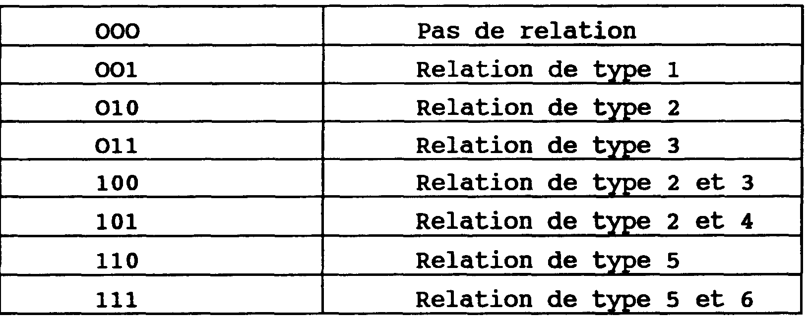
<tb> 000 <SEP> Pas <SEP> de <SEP> relation
<tb> 001 <SEP> Relation <SEP> de <SEP> type <SEP> 1
<tb> 010 <SEP> Relation <SEP> de <SEP> type <SEP> 2
<tb> 011 <SEP> Relation <SEP> de <SEP> type <SEP> 3
<tb> 100 <SEP> Relation <SEP> de <SEP> type <SEP> 2 <SEP> et <SEP> 3
<tb> 101 <SEP> Relation <SEP> de <SEP> type <SEP> 2 <SEP> et <SEP> 4
<tb> 110 <SEP> Relation <SEP> de <SEP> type <SEP> 5
<tb> 111 <SEP> Relation <SEP> de <SEP> type <SEP> 5 <SEP> et <SEP> 6
<tb>
La figure 5 représente le schéma synoptique d'un premier exemple de réalisation d'un élément mémoire, noté RMPl(X,Y), I1 peut être utilisé dans l'un quelconque des exemples de réalisation décrit ci-dessus, SN, TN, ou TN'.<tb> 000 <SEP> No <SEP> of <SEP> relationship
<tb> 001 <SEP><SEP> relationship of <SEP> type <SEP> 1
<tb> 010 <SEP><SEP> relationship of <SEP> type <SEP> 2
<tb> 011 <SEP><SEP> relationship of <SEP> type <SEP> 3
<tb> 100 <SEP><SEP> relationship of <SEP> type <SEP> 2 <SEP> and <SEP> 3
<tb> 101 <SEP><SEP> relationship of <SEP> type <SEP> 2 <SEP> and <SEP> 4
<tb> 110 <SEP><SEP> relationship of <SEP> type <SEP> 5
<tb> 111 <SEP><SEP> relationship of <SEP> type <SEP> 5 <SEP> and <SEP> 6
<Tb>
FIG. 5 represents the block diagram of a first exemplary embodiment of a memory element, denoted RMP1 (X, Y). It can be used in any of the exemplary embodiments described above, SN, TN, or TN '.
Par exemple, cet élément RMP1(X,Y) est situé au point d'intersection d'une branche BOl(X) d'un bus orthogonal relié à un point d'accès AP1(X) correspondant à un objet X, et d'une branche BO'1(Y) d'un autre bus orthogonal relié à un point d'accès AP1(Y) correspondant à un objet Y. Ces deux bus se croisent mais sans être connectés entre eux. Dans les exemples de réalisation décrits ci-après les bus sont du type comportant un conducteur pour chaque signal à transmettre. Mais il est à la portée de l'Homme de l'Art de les remplacer par d'autres arrangements de bus selon des techniques classiques, par exemple permettant de réduire le nombre de conducteurs. For example, this element RMP1 (X, Y) is located at the intersection point of a branch BO1 (X) of an orthogonal bus connected to an access point AP1 (X) corresponding to an object X, and a branch BO'1 (Y) of another orthogonal bus connected to an access point AP1 (Y) corresponding to an object Y. These two buses intersect but without being connected to each other. In the exemplary embodiments described below, the buses are of the type comprising a conductor for each signal to be transmitted. But it is within the scope of the skilled person to replace them with other bus arrangements according to conventional techniques, for example to reduce the number of drivers.
L'élément RMP1(X,Y) comporte
- une première entrée I(Y) recevant trois signaux,
STy, RTy, et RSy; cette entrée comportant, dans cet exemple, trois conducteurs qui sont reliés respectivement à trois conducteurs de la branche BO'1(Y), transmettant respectivement ces trois signaux, dans cet exemple;
- une seconde entrée I(X) recevant trois signaux STX,
RTX, et Rsx; cette entrée comportant, dans cet exemple, trois conducteurs qui sont reliés respectivement à trois conducteurs de la branche BO1(X), transmettant respectivement ces trois signaux dans cet exemple;
- une première sortie 01(Y) reliée à un conducteur de la branche BO'1(Y), transmettant le signal OLy, ce conducteur de la branche BO'1(Y) constituant un OU câblé
WOR2; ;
- une seconde sortie 01(X) reliée à un conducteur de la branche BO1(X), transmettant un signal OLX, ce conducteur constituant un OU câblé WOR3;
- une bascule 5 comportant : une entrée S de mise à 1; une entrée R de mise à O; et une sortie notée 1;
- une porte logique ET, 1, à deux entrées et une sortie, cette dernière étant reliée à l'entrée S de la bascule 5;
- une porte logique ET, 2, à deux entrées et à une sortie, cette dernière étant reliée à l'entrée R de la bascule 5;
- une porte logique ET, 3, à deux entrées et une sortie, cette dernière constituant la sortie 01(X);
- une porte logique ET, 4, à deux entrées et une sortie, cette dernière constituant la sortie 01(Y).The element RMP1 (X, Y) has
a first input I (Y) receiving three signals,
STy, RTy, and RSy; this input comprising, in this example, three conductors which are respectively connected to three conductors of the branch BO'1 (Y), respectively transmitting these three signals, in this example;
a second input I (X) receiving three signals STX,
RTX, and Rsx; this input comprising, in this example, three conductors which are respectively connected to three conductors of the branch BO1 (X), respectively transmitting these three signals in this example;
a first output 01 (Y) connected to a conductor of the branch BO'1 (Y), transmitting the signal OLy, this conductor of the branch BO'1 (Y) constituting a wired OR
WOR2; ;
a second output 01 (X) connected to a conductor of the branch BO1 (X), transmitting an OLX signal, this conductor constituting a wired OR WOR3;
a flip-flop 5 comprising: an input S set to 1; a set-up input R; and an output denoted 1;
an AND logic gate, 1, with two inputs and an output, the latter being connected to the input S of the flip-flop 5;
a logic AND gate, 2, with two inputs and an output, the latter being connected to the input R of the flip-flop 5;
an AND logic gate, 3, with two inputs and an output, the latter constituting the output 01 (X);
an AND logic gate, 4, with two inputs and an output, the latter constituting the output 01 (Y).
Les deux entrées de la porte 1 sont reliées respectivement au conducteur de la branche Bo'1(Y) fournissant le signal STp, et au conducteur de la branche
BO1(X) fournissant le signal STX, de manière à remettre à 1 la bascule 5 lorsque les signaux STy et STX sont appliqués simultanément, respectivement sur les points d'accès AP1(X) et AP1(Y) correspondant aux objets X et Y. Les deux entrées de la porte 2 sont reliées respectivement au conducteur de la branche BO'1(Y) qui fournit le signal RTy, et au conducteur de la branche BOl(X) qui fournit le signal RTX, de manière à remettre à O la bascule 5 lorsque les signaux
RTy et RTX sont appliqués simultanément, respectivement sur les points d'accès AP1(X) et AP1(Y) correspondant aux objets
X et Y.The two inputs of the gate 1 are respectively connected to the conductor of the branch Bo'1 (Y) supplying the signal STp, and to the conductor of the branch
BO1 (X) supplying the signal STX, so as to reset the flip-flop 5 when the signals STy and STX are applied simultaneously, respectively on the access points AP1 (X) and AP1 (Y) corresponding to the objects X and Y The two inputs of the gate 2 are respectively connected to the conductor of the branch BO'1 (Y) which supplies the signal RTy, and to the conductor of the branch BO1 (X) which supplies the signal RTX, so as to hand over to O the flip-flop 5 when the signals
RTy and RTX are applied simultaneously, respectively on the access points AP1 (X) and AP1 (Y) corresponding to the objects
X and Y.
Les deux entrées de la porte 3 sont reliées respectivement à la sortie 1 de la bascule 5, qui fournit un 1 lorsque cette bascule est mise à 1, et au conducteur de la branche BO'1(Y) qui fournit le signal RSy. La porte 1 transmet à la sortie O1(X) le bit mémorisé par la bascule 5, lorsque le signal RSy est appliqué au point d'accès AP1(Y) correspondant à l'objet Y, afin de recevoir la valeur de ce bit sur le point d'accès AP1(X) correspondant à l'objet X, ce bit constituant le signal OLIM. The two inputs of the gate 3 are respectively connected to the output 1 of the flip-flop 5, which provides a 1 when this flip-flop is set to 1, and to the conductor of the branch BO'1 (Y) which supplies the signal RSy. The gate 1 transmits at the output O1 (X) the bit memorized by the flip-flop 5, when the signal RSy is applied to the access point AP1 (Y) corresponding to the object Y, in order to receive the value of this bit on the access point AP1 (X) corresponding to the object X, this bit constituting the OLIM signal.
Les deux entrées de la porte 4 sont reliées respectivement à la sortie 1 de la bascule 5 et au conducteur de la branche BO1(X) qui fournit le signal RSX. The two inputs of the gate 4 are respectively connected to the output 1 of the flip-flop 5 and to the conductor of the branch BO1 (X) which supplies the signal RSX.
La porte 4 transmet vers la sortie 01(Y) le bit mémorisé par la bascule 5, lorsque le signal RSX est appliqué au point d'accès AP1(X), afin de recevoir la valeur de ce bit sur le point d'accès AP1(Y) correspondant à l'objet Y, la valeur de ce bit constituant le signal OLp.The gate 4 transmits to the output 01 (Y) the bit memorized by the flip-flop 5, when the signal RSX is applied to the access point AP1 (X), in order to receive the value of this bit on the AP1 access point (Y) corresponding to the object Y, the value of this bit constituting the signal OLp.
Cet exemple de réalisation RMP1(X,Y) permet donc de mémoriser un bit de valeur 1 dans la bascule 5 lorsque les deux signaux STX et STp sont actifs simultanément; ou de mémoriser un bit de valeur O quand les deux signaux RTX et RTp sont actifs simultanément; ou de lire le bit mémorisé dans la bascule 5, sur l'accès AP1(Y) correspondant à l'objet Y, si la lecture est commandée par le signal RSX, ou bien sur le point d'accès AP1(X) correspondant à l'objet X si la lecture est commandée par le signal RSp. Dans ce premier exemple de réalisation, chaque bus correspondant à un objet transporte des signaux qui ont deux fonctions à la fois : sélection de cet objet, et commande d'une opération. This exemplary embodiment RMP1 (X, Y) thus makes it possible to store a bit of value 1 in flip-flop 5 when the two signals STX and STp are active simultaneously; or to memorize a bit of value O when the two signals RTX and RTp are active simultaneously; or to read the bit stored in the flip-flop 5, on the access AP1 (Y) corresponding to the object Y, if the reading is controlled by the signal RSX, or on the access point AP1 (X) corresponding to the object X if the reading is controlled by the signal RSp. In this first exemplary embodiment, each bus corresponding to an object conveys signals that have two functions at the same time: selection of this object, and control of an operation.
La figure 6 représente à titre d'exemple le bus orthogonal constitué des branches BO1(K) et BO'1(K), et l'accès APî(K), qui correspondent à l'objet K. Cet accès comporte quatre conducteurs qui sont reliés respectivement aux quatre conducteurs constituant la branche BO1(K), et aux quatre conducteurs constituant la branche BO'1(K). Ces conducteurs permettent les opérations de gestion suivantes
- inscrire une information, (à savoir) un bit de valeur 1, indiquant l'existence d'une relation entre l'objet
K et un autre objet;
- inscrire une information, par exemple un bit de valeur 0, indiquant l'inexistence d'une relation entre l'objet K et un autre objet;
- lire une information, à savoir la valeur d'un bit, indiquant l'existence ou la non existence d'une relation entre l'objet K et un autre objet.FIG. 6 represents, by way of example, the orthogonal bus consisting of the branches BO1 (K) and BO'1 (K), and the access AP1 (K), which correspond to the object K. This access comprises four drivers which are respectively connected to the four conductors constituting the branch BO1 (K), and to the four conductors constituting the branch BO'1 (K). These drivers allow the following management operations
- write information, (ie) a bit of value 1, indicating the existence of a relationship between the object
K and another object;
- write information, for example a bit of value 0, indicating the absence of a relationship between the object K and another object;
- read information, namely the value of a bit, indicating the existence or non-existence of a relationship between the object K and another object.
Pour réaliser de telles opérations, les signaux de commande appliqués au point d'accès AP(K), sont respectivement les suivants
- un signal STK de commande de mise à 1;
- un signal RTK de commande de remise à O;
- un signal RSK de commande de lecture.To carry out such operations, the control signals applied to the access point AP (K) are respectively as follows
an STK control signal for setting 1;
a reset control signal RTK at O;
an RSK signal for reading control.
Un quatrième conducteur de l'accès AP1(K) est une sortie fournissant aux circuits logiques LM un signal binaire OLK résultant d'une lecture dans un ou plusieurs éléments de mémoire, les conducteurs OLK des branches OB(K) et OB'1(K) constituant un OU câblé, noté WOR1 sur la figure. A fourth driver of the access AP1 (K) is an output providing the logic circuits LM with an OLK binary signal resulting from a reading in one or more memory elements, the OLK conductors of the branches OB (K) and OB'1 ( K) constituting a wired OR, noted WOR1 in the figure.
La figure 7 représente le schéma synoptique d'une variante RMP1" (X,Y) du premier exemple de réalisation. FIG. 7 represents the block diagram of a variant RMP1 "(X, Y) of the first exemplary embodiment.
Selon cette variante, le nombre de signaux transmis par les bus correspondant respectivement aux objets est minimisé, par contre il y a un bus supplémentaire OC qui est commun pour tous les objets et qui est relié à tous les éléments de mémoire de relation. L'élément RMP1"(X,Y) est situé au point d'intersection d'une branche BO1"(X) d'un bus orthogonal relié à un point d'accès AP1"(X) correspondant à un objet X, et d'une branche BO'1"(Y) d'un autre bus orthogonal relié à un point d'accès AP1"(Y) correspondant à un objet Y.Chaque branche ne comporte que deux conducteurs, l'un transportant un signal de sélection pour sélectionner tous les éléments correspondants à un objet donné, et l'autre transportant un signal de sortie de lecture pour cet objet donné. Le bus commun OC comporte un conducteur pour chacune des opérations à commander
- un conducteur transporte un signal RT pour commander l'inscription d'une valeur 0 indiquant l'inexistence d'une relation;
- un conducteur transporte un signal ST pour commander l'inscription d'une valeur 1 indiquant l'existence d'une relation;
- un conducteur transporte un signal RD pour commander la lecture d'une information de relation.According to this variant, the number of signals transmitted by the buses respectively corresponding to the objects is minimized, on the other hand there is an additional bus OC which is common for all the objects and which is connected to all the memory elements of relation. The element RMP1 "(X, Y) is located at the intersection point of a branch BO1" (X) of an orthogonal bus connected to an access point AP1 "(X) corresponding to an object X, and of a branch BO'1 "(Y) of another orthogonal bus connected to an access point AP1" (Y) corresponding to an object Y.Each branch comprises only two conductors, one carrying a signal of selection to select all elements corresponding to a given object, and the other carrying a read output signal for that object The common bus OC has a driver for each of the operations to be controlled
a driver carries an RT signal to control the writing of a value 0 indicating the non-existence of a relation;
a conductor carries an ST signal to control the writing of a value 1 indicating the existence of a relation;
a conductor carries a signal RD for controlling the reading of a relation information.
Dans cette variante RMP1 du premier exemple de réalisation, il y a donc dissociation totale des signaux de sélection d'objet, SSX et SSyt et des signaux communs de commande d'opération : RT, ST, RD. In this variant RMP1 of the first exemplary embodiment, there is therefore complete dissociation of the object selection signals, SSX and SSyt and common operation control signals: RT, ST, RD.
Dans d'autre variantes de réalisation une dissociation partielle de ces deux fonctions est envisageable. In other embodiments, a partial dissociation of these two functions is possible.
L'élément de mémoire RMP1"(X,Y) comporte
- une bascule 5" comportant une entrée S de mise à 1, une entrée R de mise à 0, et une sortie notée 1;
- une porte logique ET, 1", à trois entrées et une sortie, cette dernière étant reliée à l'entrée S de la bascule 5";
- une porte logique ET, 2", à trois entrées et une sortie, cette dernière étant reliée à l'entrée R de la bascule 5";
- une porte logique ET, 3", à trois entrées et une sortie, cette dernière constituant une sortie de l'élément RMP1"(X,Y) et étant reliée à un conducteur de la branche
BO'1"(Y), ce conducteur acheminant un signal de sortie de lecture OLY et constituant un OU câblé WOR3"; ;
- une porte logique ET, 4", à trois entrées et une sortie, cette dernière constituant une sortie de l'élément RMPî"(X,Y) reliée à un conducteur de la branche BO '1"(X) transportant un signal de sortie de lecture OLX et constituant un OU câblé WOR2".The memory element RMP1 "(X, Y) comprises
a flip-flop 5 "having an input S set to 1, an input R set to 0, and an output denoted 1;
a logic AND gate, 1 ", with three inputs and an output, the latter being connected to the input S of the flip-flop 5";
an AND logic gate, 2 ", with three inputs and an output, the latter being connected to the input R of the flip-flop 5";
an AND logic gate, 3 ", with three inputs and an output, the latter constituting an output of the element RMP1" (X, Y) and being connected to a conductor of the branch
BO'1 "(Y), this conductor carrying a read out signal OLY and constituting a wired OR WOR3";;
a logic AND gate, 4 ", with three inputs and an output, the latter constituting an output of the element RMP" (X, Y) connected to a conductor of the branch BO '1 "(X) conveying a signal of OLX reading output and constituting a wired OR WOR2 ".
Une première entrée de la porte 1" est reliée à un conducteur de la branche BO'1"(Y) pour recevoir un signal d'adressage 55Y . Une deuxième entrée de la porte 1" est reliée à un conducteur de la branche BO1"(X) pour recevoir un signal d'adressage 55X Une première entrée et une deuxième entrée de la porte 2" sont reliées respectivement de la même façon. Quel que soit le type d'opération à réaliser, l'écriture d'un 1 ou d'un 0 dans la bascule 5", un élément RMP1"(X,Y) est sélectionné en fournissant simultanément un signal de sélection SSX = 1 sur le point d'accès AP1"(X) et un signal de sélection, SSp = 1 sur le point d'accès AP1"(Y) correspondant à l'objet Y.La nature de l'opération réalisée est déterminée par un signal de commande d'opération appliqué sur le bus commun OC. La troisième entrée de la porte 1" est reliée au conducteur du bus commun OC pour recevoir le signal ST pour écrire une valeur 1 dans la bascule 5" lorsque les trois signaux SSp, SSXI et ST sont actifs simultanément. La troisième entrée de la porte 2" est reliée au conducteur du bus commun OC fournissant le signal RT pour écrire une valeur O dans la bascule 5", lorsque les trois signaux SSyt SSX, et RT sont actifs simultanément. A first input of the gate 1 "is connected to a conductor of the branch BO'1" (Y) to receive an addressing signal 55Y. A second input of the gate 1 "is connected to a conductor of the branch BO1" (X) to receive an addressing signal 55X A first input and a second input of the gate 2 "are respectively connected in the same way. whatever the type of operation to be performed, writing a 1 or a 0 in the flip-flop 5 ", an element RMP1" (X, Y) is selected by simultaneously supplying a selection signal SSX = 1 on the access point AP1 "(X) and a selection signal, SSp = 1 on the access point AP1" (Y) corresponding to the object Y. The nature of the operation performed is determined by a signal of operation command applied on the common bus OC The third input of the gate 1 "is connected to the common bus conductor OC to receive the signal ST to write a value 1 in the flip-flop 5" when the three signals SSp, SSXI and ST are active simultaneously The third input of the gate 2 "is connected to the common bus driver OC provided The RT signal is used to write a value O into the flip-flop 5 ", when the three signals SSyt SSX, and RT are active simultaneously.
Une première entrée des portes 3" et 4" est reliée à la sortie 1 de la bascule 5". Une deuxième entrée de la porte 3" est reliée au conducteur de la branche BO'1"(Y) transportant le signal de sélection sSy. La deuxième entrée de la porte 4" est reliée au conducteur de la branche BO1"(X) transportant le signal sélection 55X La troisième entrée de la porte 3" et la troisième entrée 4" sont reliées au conducteur du bus commun OC transportant le signal RD, pour commander une lecture lorsque les deux signaux RD et 55Y sont actifs simultanément, ou bien lorsque les deux signaux RD et SSX sont actifs simultanément.Dans le premier cas, le signal de sortie de lecture est un signal OLX fourni à un conducteur de la branche BO1"(X). Dans le deuxième cas, le signal de sortie de lecture est un signal OLy fourni à un conducteur de la branche BO'1"(Y). A first input of the gates 3 "and 4" is connected to the output 1 of the flip-flop 5 "A second input of the door 3" is connected to the conductor of the branch BO'1 "(Y) carrying the selection signal sSy The second input of the gate 4 "is connected to the conductor of the branch BO1" (X) carrying the selection signal 55X The third input of the gate 3 "and the third input 4" are connected to the conductor of the common bus OC carrying the signal RD, to control a reading when both RD and 55Y signals are active simultaneously, or when both RD and SSX signals are active simultaneously. In the first case, the read output signal is an OLX signal supplied to a driver branch BO1 "(X). In the second case, the read output signal is a signal OLy supplied to a conductor of the branch BO'1 "(Y).
Naturellement d'autres variantes du premier exemple de réalisation sont à la portée de l'Homme de l'Art, en considérant toutes les variantes intermédiaires entre celles représentées sur les figures 5 et 7. Naturally other variants of the first embodiment are within the reach of those skilled in the art, considering all intermediate variants between those shown in Figures 5 and 7.
I1 est à remarquer que le caractère individuel des points d'accès correspondant aux différents objets, et des points de mémoire de relation, permet de réaliser de nombreuses opérations en parallèle. Par exemple, dans la variante de réalisation RMP1 représentée sur la figure 5, une opération de lecture à partir d'un objet X, déclenchée en envoyant le signal RSX sur l'accès AP1(X) provoque une opération de lecture dans tous les éléments de mémoire
RMP1(X,Y) pour Y = 1 à N et Y F X. Un signal logique OLy de valeur 1 apparait simultanément sur tous les accès AP1(Y) des objets Y=1,..., N et Y w X ayant une relation établie avec l'objet X considéré, c'est-à-dire dont les éléments de mémoire RMP1(X,Y) contiennent une information binaire de valeur 1.It should be noted that the individual character of the access points corresponding to the different objects, and relationship memory points, makes it possible to carry out numerous operations in parallel. For example, in the embodiment variant RMP1 shown in FIG. 5, a read operation from an object X, triggered by sending the signal RSX on the access AP1 (X), causes a read operation in all the elements of memory
RMP1 (X, Y) for Y = 1 to N and YF X. A logical signal OLy of value 1 appears simultaneously on all the accesses AP1 (Y) of the objects Y = 1, ..., N and Y w X having a established relationship with the object X considered, that is to say whose memory elements RMP1 (X, Y) contain binary information of value 1.
D'autre part, il est possible d'effectuer une opération de lecture multiple, c'est-à-dire simultanément à partir de plusieurs objets, par exemple X1,X2 et X3. Dans ce cas, un signal logique OL(Y) de valeur 1 apparaît simultanément sur tous les accès AP1(Y) des objets Y=1,...,N qui ont une relation établie avec au moins un des objets X1,X2,X3. Dans une telle opération de lecture multiple, l'ensemble des objets Y identifiés comme ayant une relation établie avec au moins un des objets X1,X2,...,Xx, est donc la réunion (au sens logique du terme) des x ensembles d'objets Y qui seraient identifiés par x lectures individuelles à partir d'un seul objet parmi X1,X2,. ..,Xx. On the other hand, it is possible to perform a multiple reading operation, that is to say simultaneously from several objects, for example X1, X2 and X3. In this case, a logic signal OL (Y) of value 1 appears simultaneously on all the accesses AP1 (Y) of the objects Y = 1,..., N which have an established relation with at least one of the objects X1, X2, X3. In such a multiple reading operation, the set of objects Y identified as having an established relation with at least one of the objects X1, X2,..., Xx, is therefore the union (in the logical sense of the term) of the x sets Y objects that would be identified by x individual readings from a single object among X1, X2 ,. .., Xx.
Outre l'identification de tous les objets ayant une relation établie avec au moins un des objets X1,X2,.. .,Xx, c'est-à-dire avec X1, ou avec X2,..., ou avec Xx, une opération de lecture multiple effectuée à partir de l'ensemble des N objets simultanément permet d'identifier tous les objets qui ont au moins une relation avec un autre objet, d'une part, et tous les objets qui n'ont aucune relation avec les autres objets d'autre part, c'est-à-dire typiquement d'identifier des objets "occupés" ou "utilisés" et des objets "libres" ou "non utilisés" respectivement.In addition to identifying all objects having an established relationship with at least one of the objects X1, X2, ..., Xx, that is, with X1, or with X2, ..., or with Xx, a multiple reading operation performed from the set of N objects simultaneously makes it possible to identify all the objects that have at least one relation with another object, on the one hand, and all the objects that have no relation with the other objects on the other hand, that is to say typically to identify "occupied" or "used" objects and "free" or "unused" objects respectively.
Une opération d'écriture déclenchée en appliquant le signal de mise à 1,STK, à n points d'accès correspondant à un sous-ensemble de n objets prédéterminés, permet de mémoriser simultanément l'existence de toutes les relations entre deux objets pour toutes les paires d'objets, réalisables avec ce sous-ensemble de n objets. De manière analogue il est possible de mémoriser l'inexistence de toutes les relations entre toutes les paires d'objets réalisables entre les objets d'un sous-ensemble de n objets en appliquant un signal de mise à zéro, RT=1, aux n points d'accès des objets de ce sous-ensemble prédéterminé. A write operation triggered by applying the setting signal 1, STK, with n access points corresponding to a subset of n predetermined objects, makes it possible simultaneously to memorize the existence of all the relations between two objects for all pairs of objects, achievable with this subset of n objects. Similarly, it is possible to memorize the inexistence of all the relations between all the pairs of realizable objects between the objects of a subset of n objects by applying a reset signal, RT = 1, to the n access points of the objects of this predetermined subset.
Dans un premier temps nous ne considérerons que des opérations réalisées sur des sous-ensembles prédéterminés, c'est-à-dire soit statiques, c 'est-à-dire dont la composition est fixée, soit dynamiques mais dont la composition est connue et gérée à l'extérieur du dispositif selon l'invention. Dans un second temps, nous considérerons des opérations plus complexes réalisées sur des sousensembles d'objets non prédéterminés, c 'est-à-dire dont la composition n'est pas nécessairement connue à l'extérieur du dispositif. In a first step we will only consider operations performed on predetermined subsets, that is to say either static, that is to say whose composition is fixed, or dynamic but whose composition is known and managed outside the device according to the invention. In a second step, we will consider more complex operations carried out on subsets of non-predetermined objects, that is to say whose composition is not necessarily known outside the device.
Lorsque les N objets sont structurés en plusieurs sous-ensembles d'objets prédéterminés dont la composition est connue à l'extérieur du dispositif, les opérations de lecture et les opérations d'écriture sont possibles comme décrit dans les paragraphes suivants. When the N objects are structured into several subsets of predetermined objects whose composition is known outside the device, read operations and write operations are possible as described in the following paragraphs.
Si une opération de lecture, à partir d'un ou plusieurs objets, doit être limitée à un sous-ensemble connu de n objets, il suffit que les circuits logiques LM comporte un circuit logique qui ne prenne en compte que les n signaux
OL venant des n points d'accès correspondant aux n objets de ce sous-ensemble. If a reading operation, from one or more objects, must be limited to a known subset of n objects, it suffices that the logic circuits LM comprise a logic circuit which takes into account only the n signals.
OL from the n access points corresponding to the n objects of this subset.
A titre d'exemple, la figure 8 illustre l'identification des relations établies entre les objets X3 et X4 constituant un sous-ensemble S1 d'un ensemble E constitué des objets X1,X2,...,X8; et les objets X5,X6,X7 constituant un autre sous-ensemble S2. Les éléments de mémoire de relation qui sont lus sont représentés par des cercles. Ils sont du type RMP1 représenté sur la figure 5. By way of example, FIG. 8 illustrates the identification of the relationships established between the objects X3 and X4 constituting a subset S1 of a set E consisting of the objects X1, X2,..., X8; and the objects X5, X6, X7 constituting another subset S2. The relationship memory elements that are read are represented by circles. They are of the RMP1 type shown in FIG.
Une telle identification peut se faire par lecture simultanée à partir des objets de l'un des sous-ensembles (S1 par exemple) et prise en compte sélective des signaux OL venant seulement des points d'accès des objets de l'autre sous-ensemble (S2 dans l'exemple choisi). Such an identification can be done by simultaneous reading from the objects of one of the subsets (S1 for example) and selective taking into account of the OL signals coming only from the access points of the objects of the other subassembly. (S2 in the example chosen).
Pour limiter la lecture aux relations concernant les objets du sous-ensemble S1, les circuits logiques LM comportent un circuit logique LA2 émettant les signaux
RS = 1 seulement sur les points d'accès AP(X3) et AP(X4) correspondant aux objets du sous-ensemble S1. Pour limiter la lecture aux relations concernant les objets du sousensemble S2, les circuits logiques LM comportent un circuit logique LB2 qui ne prend en compte que les signaux OL provenant des points d'accès AP(X5),AP(X6),AP(X7), correspondant au sous-ensemble S2. Les cercles hachurés représentent les éléments de mémoire qui sont lus mais dont l'information n'est pas prise en compte par le circuit LB2.To limit the reading to the relations concerning the objects of the subset S1, the logic circuits LM comprise a logic circuit LA2 emitting the signals
RS = 1 only on the access points AP (X3) and AP (X4) corresponding to the objects of the subset S1. To limit the reading to the relations concerning the objects of the subset S2, the logic circuits LM comprise a logic circuit LB2 which takes into account only the signals OL coming from the access points AP (X5), AP (X6), AP (X7 ), corresponding to the subset S2. The hatched circles represent the memory elements that are read but whose information is not taken into account by the circuit LB2.
Dans cet exemple, les signaux OL = 1 indiquent quels objets de l'ensemble S2 ont au moins une relation avec les objets de l'ensemble S1.In this example, the signals OL = 1 indicate which objects of the set S2 have at least one relation with the objects of the set S1.
Examinons maintenant les possibilités d'une opération d'écriture sur des sous-ensembles connus à l'extérieure du dispositif. Let us now examine the possibilities of a write operation on known subsets outside the device.
La figure 9 illustre un exemple pour n = 5. Figure 9 illustrates an example for n = 5.
Considérons un sous-ensemble S constitué de cinq objets Al, A2, , B2, B3, dans un ensemble E de huit objets (N = 8), appartenant à une même catégorie. Par exemple, l'existence de toutes les relations possibles entre ces cinq objets peut être mémorisée au moyen d'une seule opération d'écriture, en appliquant simultanément cinq signaux STK=1 respectivement aux points d'accès AP(Al),AP(A2),AP(B1), AP(B2),AP(B3), au moyen d'un circuit logique L1 appliquant une sélection du sous-ensemble S, et faisant partie des circuits logiques LM.Consider a subset S consisting of five objects Al, A2,, B2, B3, in a set E of eight objects (N = 8) belonging to the same category. For example, the existence of all the possible relations between these five objects can be memorized by means of a single write operation, by simultaneously applying five signals STK = 1 respectively to the access points AP (Al), AP ( A2), AP (B1), AP (B2), AP (B3), by means of a logic circuit L1 applying a selection of the subset S, and forming part of the logic circuits LM.
Les bus qui sont activés sont représentés en traits continus. Les bus inactivés sont représentés en pointillés.Buses that are activated are shown in solid lines. Inactivated buses are shown in dotted lines.
Les éléments de mémoire qui réalisent l'opération d'écriture sont représentés chacun par un cercle.The memory elements that perform the write operation are each represented by a circle.
I1 apparaît que l'existence de toutes les relations
A1-A2,A1-Bl,A1-B2,A1-B3,A2-Bl,A2-B2,A2-B3,B1-B2,B1-B3,B2-B3 peut être mémorisée par cette unique opération. I1 est possible d'effacer de manière analogue l'existence de toutes ces relations, en une seule opération.It appears that the existence of all relations
A1-A2, A1-B1, A1-B2, A1-B3, A2-B1, A2-B2, A2-B3, B1-B2, B1-B3, B2-B3 can be memorized by this single operation. It is possible to similarly erase the existence of all these relations in a single operation.
Cependant ce premier exemple de réalisation des éléments de mémoire ne permet pas de réaliser des opérations plus sélectives, mettant en oeuvre au moins deux sousensembles de l'ensemble E, par exemple : un sous-ensemble S1 constitué de nl=2 objets Al et A2, et un sous-ensemble S2 constitué de n2=3 objets,B1,B2,B3. I1 n'est pas possible par exemple de
- mémoriser l'existence de relations entre l'objet A1 et chacun des n2 objets B1,B2,B3, sans mémoriser l'existence de relations B1-B2,B1-B3,B2-B3 au sein du sous-ensemble S2;;
- ou mémoriser l'existence de relations entre chaque objet du sous-ensemble S1 de nl objets, A1,A2 et chaque objet du sous-ensemble S2 de n2 objets B1,B2,B3 sans mémoriser l'existence d'une relation A1-A2 entre les objets du sous-ensemble S1 et sans mémoriser l'existence d'une relation B1-B2,B1-B3,B2-B3 entre les objets du sous-ensemble
S2.However, this first exemplary embodiment of the memory elements does not make it possible to perform more selective operations, implementing at least two subsets of the set E, for example: a subset S1 consisting of n1 = 2 objects A1 and A2 , and a subset S2 consisting of n2 = 3 objects, B1, B2, B3. It is not possible, for example, to
storing the existence of relations between the object A1 and each of the n2 objects B1, B2, B3, without storing the existence of relations B1-B2, B1-B3, B2-B3 within the subset S2 ;;
or to memorize the existence of relations between each object of the subset S1 of n1 objects, A1, A2 and each object of the subset S2 of n2 objects B1, B2, B3 without memorizing the existence of a relation A1- A2 between the objects of the subset S1 and without memorizing the existence of a relationship B1-B2, B1-B3, B2-B3 between the objects of the subset
S2.
La mémorisation de 1'inexistence de relations, autrement dit l'effacement du contenu des éléments de mémoire, pose un problème similaire. Storing the existence of relationships, that is, erasing the contents of the memory elements, poses a similar problem.
La figure 10 illustre ce problème en montrant le fonctionnement du dispositif selon l'invention lorsqu'il est constitué d'éléments de mémoire RNP1 tels que celui représenté sur la figure 5. Deux circuits logiques LA1 et
LB1 activent, par des signaux STK=1, respectivement les accès : AP(A1) et AP(A2) d'une part, et AP(B1), AP(B2),
AP(B3), d'autre part, qui correspondent respectivement aux sous-ensembles S1 et S2 de l'ensemble E. Les bus activés sont représentés en traits continus. Les éléments de mémoire qui sont activés sont représentés par des cercles. Ceux qui mémorisent l'existence d'une relation entre un objet du sous-ensemble S1 et un objet du sous-ensemble S2 sont représentés en blanc.Ceux qui mémorisent l'existence d'une relation entre deux objets du même sous-ensemble, S1 ou S2, sont hachurés. I1 est souhaitable de pouvoir mémoriser ou effacer une information dans les éléments représentés en blanc, sans faire forcément la même opération dans les éléments représentés hachurés.FIG. 10 illustrates this problem by showing the operation of the device according to the invention when it consists of memory elements RNP1 such as that represented in FIG. 5. Two logic circuits LA1 and
LB1 activate, by signals STK = 1, respectively the accesses: AP (A1) and AP (A2) on the one hand, and AP (B1), AP (B2),
AP (B3), on the other hand, which respectively correspond to the subsets S1 and S2 of the set E. The activated buses are represented in solid lines. The memory elements that are enabled are represented by circles. Those which memorize the existence of a relation between an object of the subset S1 and an object of the subset S2 are represented in white.Those which memorize the existence of a relation between two objects of the same subset, S1 or S2, are hatched. It is desirable to be able to memorize or erase information in the elements represented in white, without necessarily doing the same operation in the elements represented hatched.
La figure 11 représente le schéma synoptique d'un second exemple de réalisation, RMP2(X, Y), de l'élément mémoire utilisé dans le dispositif selon l'invention. Ce second exemple de réalisation présente l'avantage de permettre une mise à 1 ou une mise à O plus sélective car il permet de modifier les relations entre deux objets appartenant respectivement à deux sous-ensembles S1 et S2, sans nécessairement modifier les relations à l'intérieur de ces sous-ensembles. Les bus n'ont pas les mêmes fonctions que dans le premier exemple de réalisation représenté sur les figures 5 et 6. Un premier bus noté OC transmet trois signaux. Dans cet exemple, ce bus comporte trois conducteurs dont le cheminement est indépendant de la disposition des éléments de mémoire car il est commun à tous les éléments de mémoire, et fournit des signaux dits banalisés commandant une opération sélectionnée parmi plusieurs opérations prédéterminées. Les trois signaux transmis sont les suivants
- un signal RT commandant la remise à O de tout élément de mémoire qui est adressé par ailleurs;
- un signal ST qui remet à 1 tout élément de mémoire qui est adressé par ailleurs;
- un signal RD qui commande une lecture dans tout élément de mémoire qui est adressé par ailleurs.FIG. 11 represents the block diagram of a second exemplary embodiment, RMP2 (X, Y), of the memory element used in the device according to the invention. This second exemplary embodiment has the advantage of making it possible to set O or more selectively, since it makes it possible to modify the relations between two objects belonging respectively to two subsets S1 and S2, without necessarily modifying the relations to inside these subsets. The buses do not have the same functions as in the first embodiment shown in FIGS. 5 and 6. A first bus denoted OC transmits three signals. In this example, this bus has three conductors whose path is independent of the arrangement of the memory elements because it is common to all the memory elements, and provides so-called unmarked signals controlling a selected operation among several predetermined operations. The three signals transmitted are the following
an RT signal controlling the delivery to O of any memory element that is addressed elsewhere;
a signal ST which gives to 1 any element of memory which is addressed elsewhere;
an RD signal which controls a reading in any memory element which is addressed elsewhere.
Ce premier bus OC est relié à trois entrées du dispositif, non représentées. Ces trois entrées sont indépendantes des points d'accès individuels qui correspondent respectivement aux N objets du dispositif de gestion. This first OC bus is connected to three inputs of the device, not shown. These three inputs are independent of the individual access points corresponding respectively to the N objects of the management device.
Chaque élément RMP2 est situé au point d'intersection de deux bus individuels correspondant respectivement à deux objets, ces deux bus pouvant être du type bus de ligne, respectivement de colonne, ou du type bus orthogonal, qui ont été décrits en référence aux figures 1 et 3. Considérons par exemple deux bus du type bus orthogonal. Un premier bus orthogonal comporte notamment une branche B02(X) et est relié à un point d'accès AP2(X) correspondant à un objet X. Each RMP2 element is situated at the intersection point of two individual buses respectively corresponding to two objects, these two buses possibly being of the line bus or column type, or of the orthogonal bus type, which have been described with reference to FIGS. and 3. Consider, for example, two bus of the orthogonal bus type. A first orthogonal bus notably comprises a branch B02 (X) and is connected to an access point AP2 (X) corresponding to an object X.
Un second bus orthogonal comporte notamment une branche
BO'2(Y) et est relié à un point d'accès AP2(Y) correspondant à un objet Y. La branche B02(X) transmet trois signaux. Dans cet exemple, elle comporte trois conducteurs transmettant respectivement:
- un signal SSAX d'adressage et de sélection de groupe
A pour l'écriture, ou d'adressage pour la lecture;
- un signal SSBX d'adressage et de sélection de groupe
B pour l'écriture;
- un signal de sortie, OLX, résultant de la lecture des éléments de mémoire RMP2(X, Y) reliés au bus orthogonal correspondant à l'accès AP2(X), chaque élément RMP2(X, Y) possédant une sortie 02(X) qui est reliée à un même conducteur de la branche LC2(X) pour constituer un OU câblé
WOR5.A second orthogonal bus includes a branch
BO'2 (Y) and is connected to an access point AP2 (Y) corresponding to an object Y. The branch B02 (X) transmits three signals. In this example, it comprises three conductors transmitting respectively:
- SSAX addressing and group selection signal
A for writing, or addressing for reading;
an SSBX addressing and group selection signal
B for writing;
an output signal, OLX, resulting from the reading of the memory elements RMP2 (X, Y) connected to the orthogonal bus corresponding to the access AP2 (X), each element RMP2 (X, Y) having an output O2 (X ) which is connected to the same conductor of the LC2 (X) branch to form a wired OR
WOR5.
La branche BO'2(Y) transmet trois signaux. Dans cet exemple, elle comporte trois conducteurs transmettant respectivement
- un signal SSAY d'adressage et de sélection de groupe
A pour l'écriture, ou d'adressage pour la lecture,
- un signal SSBy d'adressage et de sélection de groupe
B pour l'écriture;
- un signal de sortie, OLy, résultant de la lecture des éléments de mémoire RMP2(X,Y) reliés au bus orthogonal correspondant au point d'accès AP2(Y), ceux-ci ayant chacun une sortie 02(Y) reliée à un même conducteur de la branche
BO'2(Y) pour constituer un OU câblé WOR5.The branch BO'2 (Y) transmits three signals. In this example, it has three drivers respectively transmitting
- an SSAY addressing and group selection signal
A for writing, or addressing for reading,
an SSBy addressing and group selection signal
B for writing;
an output signal, OLy, resulting from the reading of the memory elements RMP2 (X, Y) connected to the orthogonal bus corresponding to the access point AP2 (Y), these each having an output 02 (Y) connected to the same conductor of the branch
BO'2 (Y) to form a wired OR WOR5.
Pour la lecture, il n'y a pas de sélection de groupe A ou B, un seul signal d'adressage suffit
SSAy = 1 sur le bus BO'2(Y) en cas de lecture à partir de l'objet Y, ou SSAX=1 sur le bus B02(X) en cas de lecture à partir de l'objet X.For playback, there is no selection of group A or B, only one addressing signal suffices
SSAy = 1 on bus BO'2 (Y) when reading from object Y, or SSAX = 1 on bus B02 (X) when reading from object X.
Pour l'écriture, un objet K peut appartenir à l'un et/ou à l'autre des deux groupes A et B selon les signaux
SSAK et SSBK qui sont activés sur l'accès AP(K)
- si SSAK =1 et SSBK=O, l'objet K appartient seulement au groupe A, pour l'écriture, - si SSAK= O et SSBK=1, l'objet K appartient seulement au groupe B, pour l'écriture,
- si SSAK=O et SSBK=O, l'objet K n'appartient à aucun des groupes A et B (aucun des éléments de mémoire mémorisant l'existence ou l'inexistence des relations de l'objet K avec d'autres objets n'est activé),
- si SSAK= 1 et SSBK= 1, l'objet K appartient à la fois au groupe A et au groupe B. For writing, an object K may belong to one and / or the other of the two groups A and B according to the signals
SSAK and SSBK that are enabled on AP (K) access
- if SSAK = 1 and SSBK = O, object K belongs only to group A, for writing, - if SSAK = O and SSBK = 1, object K belongs only to group B, for writing,
- if SSAK = O and SSBK = O, the object K does not belong to any of the groups A and B (none of the memory elements memorizing the existence or nonexistence of the relations of the object K with other objects is enabled),
if SSAK = 1 and SSBK = 1, the object K belongs to both group A and group B.
Cet exemple d'élément de mémoire RMP2(X,Y), illustré sur la figure 11, comporte
- deux entrées, IA(Y) et IA(X), de sélection en écriture, qui sont reliées respectivement au conducteur transmettant le signal SSAy dans la branche BO'2(Y), et au conducteur transmettant le signal SSAX dans la branche
B02(X);
- deux entrées, IB(Y) et IB(X), de sélection en écriture, qui sont reliées respectivement au conducteur transmettant le signal SSBY dans la branche BO'2(Y) et au conducteur transmettant le signal SSBX dans la branche
B02(X);
- une entrée banalisée de remise à 0, I2, reliée au conducteur du bus OC transmettant le signal RT;
- une entrée banalisée de mise à 1, I1, reliée au conducteur du bus OC transmettant le signal ST;;
- une entrée banalisée de commande lecture, I5, reliée au conducteur du bus OC transmettant le signal RD;
- deux entrées de sélection en lecture, I3 et I4, qui sont reliées respectivement au conducteur transmettant le signal SSAy dans la branche B02'(Y) et au conducteur transmettant le signal SSAX dans la branche B02(X);
- les sorties 02(Y) et 02(X) mentionnées précédemment;
- deux portes ET, 11 et 12, ayant chacune une première entrée, une seconde entrée, et une sortie; les premières entrées des portes 11 et 12 constituant les entrées IB(Y) et IA(Y); et les secondes entrées des portes 11 et 12 constituant les entrées IA(X) et IB(X);
- une porte OU, 13, ayant deux entrées reliées respectivement aux deux sorties des portes 11 et 12, et ayant une sortie;
- deux portes ET, 14 et 15, ayant chacune une première entrée, une seconde entrée, et une sortie ; les premières entrées étant reliées ensemble à la sortie de la porte OU 13; les secondes entrées des portes 14 et 15 constituant respectivement les entrées I1 et I2 de remise à
O et de remise à 1 de l'élément RMP2(X, Y);
- une bascule 16 ayant : une entrée de remise à 1, notée S, reliée à la sortie de la porte 14; une entrée de remise à 0, notée R, reliée à la sortie de la porte 15; et une sortie;
- deux portes ET, 17 et 18, ayant chacune une première entrée, une deuxième entrée, une troisième entrée, et une sortie; les premières entrées des portes 17 et 18 étant reliées ensemble et constituant l'entrée I5 de commande de lecture; les deuxièmes entrées des portes 17 et 18 constituant respectivement les entrées I3 et I4 de sélection en lecture, les troisièmes entrées des portes 17 et 18 étant reliées ensemble à la sortie de la bascule 16, et les sorties des portes 17 et 18 constituant respectivement les sorties 02(Y) et 02(X).This exemplary memory element RMP2 (X, Y), illustrated in FIG. 11, comprises
two inputs, IA (Y) and IA (X), of writing selection, which are respectively connected to the conductor transmitting the signal SSAy in the branch BO'2 (Y), and to the conductor transmitting the signal SSAX in the branch
B02 (X);
two inputs, IB (Y) and IB (X), in writing selection, which are respectively connected to the conductor transmitting the signal SSBY in the branch BO'2 (Y) and to the conductor transmitting the signal SSBX in the branch
B02 (X);
an unencrypted reset input, connected to the driver of the OC bus transmitting the RT signal;
- an unmarked input 1, I1, connected to the bus driver OC transmitting the signal ST ;;
an ordinary read control input, I5, connected to the driver of the bus OC transmitting the signal RD;
two read selection inputs, I3 and I4, which are respectively connected to the conductor transmitting the signal SSAy in the branch B02 '(Y) and to the conductor transmitting the signal SSAX in the branch B02 (X);
the outputs 02 (Y) and 02 (X) mentioned above;
two AND gates, 11 and 12, each having a first input, a second input, and an output; the first inputs of the gates 11 and 12 constituting the inputs IB (Y) and IA (Y); and the second inputs of the gates 11 and 12 constituting the inputs IA (X) and IB (X);
an OR gate, 13, having two inputs respectively connected to the two outputs of the gates 11 and 12, and having an output;
two AND gates, 14 and 15, each having a first input, a second input, and an output; the first inputs being connected together at the output of the OR gate 13; the second inputs of the doors 14 and 15 respectively constituting the inputs I1 and I2 of delivery to
O and reset the element RMP2 (X, Y) to 1;
a flip-flop 16 having: reset input 1, denoted S, connected to the output of the door 14; a reset input, denoted R, connected to the output of the gate 15; and an output;
two AND gates, 17 and 18, each having a first input, a second input, a third input, and an output; the first inputs of the gates 17 and 18 being connected together and constituting the read control input I5; the second inputs of the gates 17 and 18 respectively constituting the I3 and I4 read selection inputs, the third inputs of the gates 17 and 18 being connected together to the output of the flip-flop 16, and the outputs of the gates 17 and 18 constituting respectively the outputs 02 (Y) and 02 (X).
La figure 12 représente un bus orthogonal et un point d'accès AP(K) correspondant à un objet K pris à titre d'exemple. Ce bus orthogonal comporte deux branches
B02(K) et BO'2(K). Le point d'accès AP2(K) comporte
- un conducteur relié à un conducteur de la branche
B02(K) et à un conducteur de la branche BO'2(K) pour transmettre le signal SSAK;
- un conducteur relié à un conducteur de la branche
B02(K) et à un conducteur de la branche BO'2(K) pour transmettre le signal SSBK;
- un conducteur relié à un conducteur de la branche
B02(K) et à un conducteur de la branche BO'2(K) pour recevoir un signal OLK en constituant un OU câblé WOR6. FIG. 12 represents an orthogonal bus and an access point AP (K) corresponding to an object K taken as an example. This orthogonal bus has two branches
B02 (K) and BO'2 (K). The access point AP2 (K) comprises
- a conductor connected to a conductor of the branch
B02 (K) and to a conductor of the branch BO'2 (K) for transmitting the SSAK signal;
- a conductor connected to a conductor of the branch
B02 (K) and a conductor of the BO'2 branch (K) for transmitting the signal SSBK;
- a conductor connected to a conductor of the branch
B02 (K) and a conductor of the BO'2 branch (K) to receive an OLK signal by forming a wired OR WOR6.
Au niveau d'un élément de mémoire de relation RMP2(X, Y) relatif aux objets X et Y, une opération d'écriture dans l'élément de mémoire est réalisée lorsque les 2 conditions suivantes sont réalisées sur les bus de commande
- ST = 1 ou RT = 1, sur le bus commun OC, respectivement pour écrire 1 ou 0;
- SSAX = 1 et SSBy = 1, ou SSBX = 1 et SSAy = 1, sur les bus de commande B02(X) et B02'(Y) respectivement.At a relationship memory element RMP2 (X, Y) relating to the objects X and Y, a write operation in the memory element is performed when the following 2 conditions are fulfilled on the control buses
- ST = 1 or RT = 1, on the common bus OC, respectively to write 1 or 0;
- SSAX = 1 and SSBy = 1, or SSBX = 1 and SSAy = 1, on the control buses B02 (X) and B02 '(Y) respectively.
Selon cette dernière condition logique, SSAX.SSBp +
SSBX. SSAp = 1, un élément de mémoire de relation RMP2(X,
Y) est sélectionné, pour l'écriture, chaque fois que l'objet X appartient à un au moins l'un des groupes A ou B (SSAX=1 ou SSBX=1) et que l'autre objet Y appartient au moins à l'autre groupe, respectivement B ou A (SSBy = 1 ou SSAp = 1), indépendamment du fait que chacun des objets X et Y appartienne à un seul groupe ou aux deux groupes.According to this last logical condition, SSAX.SSBp +
SSBX. SSAp = 1, a memory element of relation RMP2 (X,
Y) is selected, for writing, whenever the object X belongs to at least one of groups A or B (SSAX = 1 or SSBX = 1) and the other object Y belongs to at least one of the other group, respectively B or A (SSBy = 1 or SSAp = 1), regardless of whether each of the objects X and Y belong to a single group or to both groups.
Pour la lecture, cet élément de mémoire RMP2(X, Y) est commandé de la manière suivante : la lecture des relations existant entre l'objet K et tout autre objet L (sans distinguer des groupes A et B) est réalisée en faisant RD=1 sur le bus OC, ce signal étant commun pour tous les éléments de mémoire, et en faisant SSAK = 1 sur l'accès AP(K) correspondant à l'objet K considéré (le signal SSBK est sans effet pour la lecture). Un signal OLi= 1 apparaît alors sur chaque point d'accès AP(i) correspondant aux objets i ayant une relation établie avec
K, c'est-à-dire dont l'élément de mémoire RMP2(K, Li) contient une information binaire de valeur 1.For reading, this memory element RMP2 (X, Y) is controlled in the following way: the reading of the relations existing between the object K and any other object L (without distinguishing between groups A and B) is carried out by doing R = 1 on the bus OC, this signal being common for all the elements of memory, and while making SSAK = 1 on the access AP (K) corresponding to the object K considered (the signal SSBK has no effect for the reading) . A signal OLi = 1 then appears on each access point AP (i) corresponding to the objects i having an established relation with
K, that is to say whose memory element RMP2 (K, Li) contains a bit information of value 1.
Cette lecture est illustrée par la figure 13. Elle représente les circuits logiques LM qui gèrent les relations d'un ensemble E constitué de huit objets : X1, ..., X8. La figure 13 illustre la lecture des éléments de mémoire de relation entre l'objet X6 et tous les autres objets de l'ensemble E. Un circuit logique L2 fournit un signal SSA = 1 (le signal SSB étant quelconque pour la lecture) à l'accès AP(X6). Les éléments de mémoire lus par l'application simultanée du signal RD=1 sur le bus commun et du signal SSA= 1 sont représentés respectivement par des cercles.This reading is illustrated in FIG. 13. It represents the logic circuits LM that manage the relations of a set E consisting of eight objects: X1, ..., X8. FIG. 13 illustrates the reading of the memory elements of relationship between the object X6 and all the other objects of the set E. A logic circuit L2 provides a signal SSA = 1 (the signal SSB being arbitrary for the reading). AP access (X6). The memory elements read by the simultaneous application of the signal RD = 1 on the common bus and the signal SSA = 1 are respectively represented by circles.
Comme dans le cas des éléments de mémoire précédents
RMP1, si la lecture doit être limitée à un sous-ensemble connu de l'ensemble X1, ..., X5, X7, X8, il suffit que les circuits logiques LM comportent un circuit logique qui ne prenne en compte que les signaux OL venant des points d'accès correspondant à ce sous-ensemble. Par exemple, pour lire l'information indiquant l'existence ou non d'une relation entre l'objet X6 et un seul autre objet, X3 par exemple, il suffit de tester la valeur du signal OL3, 1 ou 0, fournie par l'accès AP(X3), au moyen d'un circuit logique L3 relié à cet accès.As in the case of previous memory elements
RMP1, if the reading must be limited to a known subset of the set X1, ..., X5, X7, X8, it suffices that the logic circuits LM comprise a logic circuit which takes into account only the OL signals from the access points corresponding to this subset. For example, to read the information indicating the existence or not of a relationship between the object X6 and a single other object, X3 for example, it is sufficient to test the value of the signal OL3, 1 or 0, provided by the AP access (X3), by means of a logic circuit L3 connected to this access.
Plus généralement, le deuxième exemple de réalisation
RMP2(X, Y) permet d'effectuer les mêmes opérations de lecture que le premier exemple RMP1(X, Y) : opération de lecture simple ou multiple (simultanée à partir de plusieurs objets); identification de relations établies entre objets de deux sous-ensembles (cas illustré par la figure 8 avec RMP1(X, Y)).More generally, the second exemplary embodiment
RMP2 (X, Y) makes it possible to perform the same read operations as the first example RMP1 (X, Y): single or multiple reading operation (simultaneous from several objects); identification of relationships established between objects of two subsets (case illustrated in Figure 8 with RMP1 (X, Y)).
Selon une variante de réalisation de l'élément
RMP1(X, Y) ou de l'élément RMP2(X,Y), lorsque cet élément de mémoire réalise une opération de lecture, il restitue une information de relation simultanément sur le bus individuel BOl(X), respectivement B02(X), correspondant à un premier objet, et sur le but individuel BO'(Y), respectivement BO'2(Y), correspondant à un second objet, s'il reçoit un signal de sélection par au moins un de ces deux bus individuels, ainsi qu'un signal de commande de lecture. Lorsque cette variante de réalisation est utilisée, les moyens logiques LM doivent être adaptés à cette variante, c'est-à-dire être capables de distinguer parmi les signaux de sortie de lecture celui qui est fourni par l'accès où est appliqué le signal de sélection, et celui ou ceux fournis par d'autres accès.According to a variant embodiment of the element
RMP1 (X, Y) or the element RMP2 (X, Y), when this memory element performs a read operation, it restores relationship information simultaneously on the individual bus BO1 (X), respectively B02 (X) corresponding to a first object, and to the individual goal BO '(Y), respectively BO'2 (Y), corresponding to a second object, if it receives a selection signal by at least one of these two individual buses, as well as a read command signal. When this variant embodiment is used, the logic means LM must be adapted to this variant, that is to say be able to distinguish among the read output signals that which is provided by the access where the signal is applied. and those provided by other accesses.
En ce qui concerne les opérations d'écriture, le deuxième exemple de réalisation RMP2(X,Y) permet d'effectuer
- les mêmes opérations d'écriture que celles permises par le premier exemple de réalisation
RMP1(X, Y), c'est-à-dire des opérations non sélectives effectuées sur un seul sous-ensemble prédéterminé de n objets;
- en outre des opérations d'écriture particulières, c'est-à-dire effectuées sélectivement entre les nl objets d'un premier sous-ensemble et les n2 objets d'un deuxième sous-ensemble, les deux sous-ensembles étant prédéterminés.With regard to the write operations, the second exemplary embodiment RMP2 (X, Y) makes it possible to perform
the same writing operations as those permitted by the first embodiment
RMP1 (X, Y), i.e., non-selective operations performed on a single predetermined subset of n objects;
in addition, particular write operations, that is to say selectively performed between the nl objects of a first subset and the n2 objects of a second subset, the two subsets being predetermined.
Avec ce deuxième exemple de réalisation, pour effectuer une opération d'écriture non sélective sur un groupe de n objets, c'est-à-dire sur toutes les relations entre ces n objets pris deux à deux, il suffit d'émettre simultanément les signaux suivants
- ST = 1 ou RT = 1 (mise à 1 ou à 0 respectivement)
sur le bus de commande commun OC;
- SSAK = 1 et SSBK = 1 sur chaque point d'accès AP(K)
correspondant à un objet K appartenant au sous
ensemble considéré de n objets.With this second embodiment, to perform a nonselective write operation on a group of n objects, that is to say on all the relations between these n objects taken two by two, it is sufficient to simultaneously transmit the following signals
- ST = 1 or RT = 1 (set to 1 or to 0 respectively)
on the OC common control bus;
- SSAK = 1 and SSBK = 1 on each access point AP (K)
corresponding to a K object belonging to the sub
considered set of n objects.
En effet, en affectant chacun des n objets considérés à la fois au groupe A et au groupe B pour cette opération d'écriture (SSAK = 1 et SSBK=1), chaque élément de mémoire de relation RMP2(X, Y), relatif à deux objets X et Y appartenant au sous-ensemble considéré de n objets, recevra les signaux SSAX = 1 et SSBX par le bus de commande B02(X) de l'objet X, et recevra SSAy = 1 et SSBp = 1 par le bus de commande B02'(Y) de l'objet Y. Chaque élément RMP2(X, Y) exécutera donc l'opération d'écriture pour la relation X-Y, puisque l'un des objets (X, Y) est sélectionné par l'un des groupes (A, B) et l'autre objet (Y, X) est sélectionné par l'autre groupe (B, A), ceci étant d'ailleurs vérifié de façon redondante pour les deux permutations des groupes A et B dans ce cas. By assigning each of the n objects considered at the same time to the group A and to the group B for this write operation (SSAK = 1 and SSBK = 1), each relative memory element RMP2 (X, Y) relative to two objects X and Y belonging to the considered subset of n objects, will receive the signals SSAX = 1 and SSBX by the control bus B02 (X) of the object X, and will receive SSAy = 1 and SSBp = 1 by the control bus B02 '(Y) of the object Y. Each element RMP2 (X, Y) will thus execute the write operation for the relation XY, since one of the objects (X, Y) is selected by the one of the groups (A, B) and the other object (Y, X) is selected by the other group (B, A), which is also redundantly verified for the two permutations of groups A and B in that case.
La méthode décrite ci-dessus est valable pour un sous-ensemble de n objets où 2 S n S N. Toutefois, on peut noter qu'une autre méthode peut être utilisée dans le cas particulier n = 2, c'est-à-dire une opération d'écriture d'une relation simple entre deux objets X et Y, à savoir en affectant arbitrairement l'un des objets X à l'un des groupes A ou B et l'autre objet Y à l'autre groupe B ou A respectivement, pour cette opération. Dans ce cas, les signaux émis simultanément sont
- ST = 1 ou RT= 1 (mise en 1 ou en 0) sur le bus
commun OC,
- SSAX = 1 et SSBX = 0 sur le bus de commande de
l'objet X, et SSAy = O et SSBy = 1 sur le bus de
commande de l'objet Y, ou bien SSAX = O et SSBX = 1
sur le bus de commande de l'objet X, et SSAy = 1 et
SSBy= 0 sur le bus de commande de l'objet Y.The method described above is valid for a subset of n objects where 2 S n S N. However, it can be noted that another method can be used in the particular case n = 2, ie to say an operation of writing a simple relation between two objects X and Y, namely by arbitrarily assigning one of the objects X to one of the groups A or B and the other object Y to the other group B or A respectively, for this operation. In this case, the signals transmitted simultaneously are
- ST = 1 or RT = 1 (set to 1 or 0) on the bus
common OC,
- SSAX = 1 and SSBX = 0 on the control bus of
object X, and SSAy = O and SSBy = 1 on the bus of
command of the object Y, or SSAX = O and SSBX = 1
on the control bus of object X, and SSAy = 1 and
SSBy = 0 on the control bus of object Y.
L'élément de mémoire RMP2(X, Y) concerné peut également exécuter l'opération d'écriture pour la relation
X-Y selon cette autre méthode lorsque n=2.The concerned memory element RMP2 (X, Y) can also perform the write operation for the relationship
XY according to this other method when n = 2.
Examinons maintenant les opérations d'écriture particulières permises par le deuxième exemple de réalisation RMP2(X, Y), c'est-à-dire effectuées sélectivement entre les nl objets d'un premier sousensemble prédéterminé et les n2 objets d'un deuxième sousensemble prédéterminé, sans nécessairement modifier les relations entre les objets d'un même sous-ensemble prédéterminé (on suppose que les deux sous-ensembles ne sont pas identiques et que nl et/ou n2 est supérieur à 1). Let us now examine the particular writing operations permitted by the second exemplary embodiment RMP2 (X, Y), that is to say carried out selectively between the nl objects of a first predetermined subset and the n2 objects of a second subset. predetermined, without necessarily modifying the relations between the objects of the same predetermined subset (it is assumed that the two subsets are not identical and that n1 and / or n2 is greater than 1).
Dans le cas d'une opération d'écriture des relations entre des objets appartenant à deux sous-ensembles disjoints ou non disjoints, l'écriture d'une information (1 ou 0) indiquant l'existence ou l'inexistence des relations entre les nl objets du premier sous-ensemble prédéterminé et les n2 objets du second sous-ensemble prédéterminé, est réalisée en affectant, pour cette opération, les nl objets du premier sous-ensemble arbitrairement à l'un des groupes
A ou B (utilisation des signaux de sélection SSA et SSB) et les n2 objets du second sous-ensemble à l'autre groupe B ou
A respectivement.In the case of an operation of writing relations between objects belonging to two disjoint or non-disjoint subsets, the writing of information (1 or 0) indicating the existence or non-existence of relations between the nl objects of the first predetermined subset and the n2 objects of the second predetermined subset, is realized by assigning, for this operation, the nl objects of the first subset arbitrarily to one of the groups
A or B (using the SSA and SSB selection signals) and the n2 objects of the second subset to the other group B or
A respectively.
Pour clarifier le fonctionnement de telles opérations d'écriture sélectives entre deux sous-ensembles d'objets prédéterminés, il faut distinguer deux cas selon que les sous-ensembles prédéterminés de nl et n2 objets sont disjoints (chaque objet n'appartient qu'à un seul sousensemble) ou bien non disjoints (au moins un objet appartient aux deux sous-ensembles). En effet, dans le premier cas chaque objet n'est présent que dans un seul groupe (A ou B), et les signaux de sélection utilisés pour un tel objet sont soit SSA=1 et SSB=O s'il appartient au groupe A, soit SSA=O et SSB=1 s'il appartient au groupe B pour l'opération.Par contre, dans le deuxième cas où les nl et n2 objets constituent des sous-ensembles non disjoints, au moins un des objets considérés (parmi nl+n2 obj ets) est commun aux deux sous-ensembles prédéterminés, et pour chacun de tels objets communs les deux signaux de sélection sont activés simultanément, SSA=1 et SSB=1, puisqu'il appartient aux deux groupes A et B pour cette opération. To clarify the operation of such selective write operations between two subsets of predetermined objects, two cases must be distinguished according to whether the predetermined subsets of n1 and n2 objects are disjoint (each object belongs to only one only subset) or not disjoint (at least one object belongs to both subsets). Indeed, in the first case each object is only present in one group (A or B), and the selection signals used for such an object are either SSA = 1 and SSB = O if it belongs to group A SSA = O and SSB = 1 if it belongs to group B for the operation. In contrast, in the second case where the n1 and n2 objects constitute non-disjoint subsets, at least one of the considered objects (among nl + n2 obj ets) is common to the two predetermined subsets, and for each of these common objects the two selection signals are activated simultaneously, SSA = 1 and SSB = 1, since it belongs to both groups A and B for this operation.
Une telle opération d'écriture sélective entre deux sous-ensembles prédéterminés disjoints ou non disjoints est donc effectuée en émettant simultanément les signaux suivants
- ST = 1 ou RT =1 (mise en 1 ou en 0) sur le bus
commun OC;
- SSAL = 1 et SSBL=O sur le bus de commande de chaque
objet L qui doit être affecté seulement au groupe A;
- SSAM = o et SSBM = 1 sur le bus de commande de chaque objet M qui doit être affecté seulement au groupe B;
- SSAN = 1 et SSBN = 1 sur le bus de commande de chaque objet N qui doit être affecté à la fois au groupe A et au groupe B (objet commun).Such a selective write operation between two predetermined disjoint or non-disjoint subsets is thus performed by simultaneously transmitting the following signals
- ST = 1 or RT = 1 (set to 1 or 0) on the bus
common OC;
- SSAL = 1 and SSBL = O on the control bus of each
object L to be assigned only to group A;
- SSAM = o and SSBM = 1 on the control bus of each object M to be assigned only to group B;
- SSAN = 1 and SSBN = 1 on the control bus of each N object to be assigned to both group A and group B (common object).
Les figures 14 et 15 illustrent respectivement ces deux procédés équivalents pour écrire l'existence ou l'inexistence de relations entre les objets Al, A2 d'un sous-ensemble S1, d'une part; et les objets B1, B2, B3 d'un sous-ensemble S2, d'autre part, les deux sous-ensembles S1 et S2 étant supposés disjoints. FIGS. 14 and 15 respectively illustrate these two equivalent methods for writing the existence or non-existence of relations between the objects A1, A2 of a subset S1, on the one hand; and the objects B1, B2, B3 of a subset S2, on the other hand, the two subsets S1 and S2 being assumed to be disjoint.
sur ces figures, les signaux d'adressage et sélection sont distingués de la façon suivante
- SSA = 1 : Trait fort continu
- SSB = 1 : Traits fort discontinu
- SSA = 0 : trait fin continu
- SSB = 0 : Trait fin discontinu.in these figures, the addressing and selection signals are distinguished as follows
- SSA = 1: Strong continuous line
- SSB = 1: Strong discontinuous traits
- SSA = 0: continuous fine line
- SSB = 0: Discontinuous fine line.
D'autre part, les éléments de mémoire qui exécutent une opération d'écriture sont indiqués par un cercle. On the other hand, memory elements that perform a write operation are indicated by a circle.
Il est à remarquer que, contrairement à ce qui passait avec le premier exemple de réalisation RMP1 (cas illustré sur la figure 8), le second exemple de réalisation
RMP2 ne provoque pas l'écriture d'informations indiquant l'existence ou l'inexistence de relations entre les objets
Al et A2 du même sous-ensemble S1, ni entre les objets B1,
B2, B3, du même sous-ensemble S2, lorsque les sousensembles S1 et S2 sont disjoints comme supposé pour le cas des figures 14 et 15. Par contre, l'existence d'un ou plusieurs objets communs à deux sous-ensembles, lorsque ces derniers sont non disjoints, a pour effet d'écrire certaines relations à l'intérieur d'un même sous-ensemble (voir plus loin le cas illustré par la figure 18).It should be noted that, contrary to what happened with the first exemplary embodiment RMP1 (as illustrated in FIG. 8), the second exemplary embodiment
RMP2 does not cause the writing of information indicating the existence or non-existence of relations between objects
A1 and A2 of the same subset S1, or between the objects B1,
B2, B3, of the same subset S2, when the subsets S1 and S2 are disjoint as assumed for the case of Figures 14 and 15. On the other hand, the existence of one or more objects common to two subsets, when the latter are not disjoint, has the effect of writing some relations within the same subset (see below the case illustrated in Figure 18).
Pour l'exemple représenté sur la figure 14, les circuits logiques LM comportent
- un cicuit logique LA3 fournissant des signaux SSA=1 et SSB=O aux accès AP(A1) et AP(A2) des objets du sousensemble S1 affectés au groupe A;
- un circuit logique LB3 fournissant des signaux
SSA=O et SSB=1 aux accès AP(B1), AP(B2), AP(B3) des objets du sous-ensemble S2 affectés au groupe B.For the example shown in FIG. 14, the logic circuits LM comprise
a logic circuit LA3 providing signals SSA = 1 and SSB = O to the AP (A1) and AP (A2) accesses of the objects of subsystem S1 assigned to group A;
an LB3 logic circuit providing signals
SSA = O and SSB = 1 at AP (B1), AP (B2), AP (B3) accesses of subset S2 objects assigned to group B.
Tous les autres signaux SSA et SSB des autres accès, ont une valeur 0. Les circuits logiques LM fournissent le signal d'écriture ST = 1 ou RT = 1 (mise à 1 ou à 0 respectivement) au bus commun qui n'est pas représenté. All other SSA and SSB signals of the other ports have a value of 0. The logic circuits LM provide the write signal ST = 1 or RT = 1 (set to 1 or to 0 respectively) to the common bus which is not represent.
Dans d'autres exemples où certains objets doivent être affectés à la fois au groupe A et au groupe B, un circuit logique LAB est prévu pour fournir les signaux SSA = 1 et SSB = 1 aux points d'accès correspondant à ces objets. Ce circuit logique LAB n'étant pas utilisé pour l'exemple illustré par les figures 14 et 15, il est représenté en pointillés. In other examples where certain objects must be assigned to both group A and group B, a logic circuit LAB is provided to provide signals SSA = 1 and SSB = 1 to the access points corresponding to these objects. As this logic circuit LAB is not used for the example illustrated in FIGS. 14 and 15, it is shown in dotted lines.
Pour l'exemple représenté sur la figure 15, les circuits logiques LM comportent
- un circuit logique LA4 fournissant des signaux
SSA=O et SSB=1 aux accès AP(A1) et AP(A2) des objets du sous-ensemble S1 affectés au groupe B;
- et un circuit logique LB4 fournissant des signaux
SSA=1 et SSB= O aux accès AP(B1), AP(B2), AP(B3) des objets du sous-ensemble S2 affectés au groupe A.For the example shown in FIG. 15, the logic circuits LM comprise
an LA4 logic circuit providing signals
SSA = O and SSB = 1 at AP (A1) and AP (A2) accesses of subset objects S1 assigned to group B;
and an LB4 logic circuit providing signals
SSA = 1 and SSB = O at AP (B1), AP (B2), AP (B3) accesses of subset S2 objects assigned to group A.
Tous les autres signaux SSA et SSB des autres accès ont une valeur 0. Les circuits logiques LM fournissent le signal d'écriture ST=1 ou RT=1 (mise en 1 ou en O respectivement) au bus commun qui n'est pas représenté. All the other SSA and SSB signals of the other ports have a value of 0. The logic circuits LM provide the write signal ST = 1 or RT = 1 (set to 1 or O respectively) to the common bus which is not represented. .
La figure 16 illustre le cas d'une structure de bus d'une variante de réalisation du réseau d'éléments de mémoire du dispositif selon l'invention. Ce réseau est encore constitué des éléments de mémoires RMP1 représentés sur la figure 5 mais les conducteurs transmettant les signaux RTK et STK dans la branche BO(K) ne sont plus reliés aux conducteurs homologues de la branche BO'(K) comme c'est représenté sur la figure 6. Selon cette variante, les deux branches sont ici commandées indépendamment pour l'écriture. FIG. 16 illustrates the case of a bus structure of an alternative embodiment of the network of memory elements of the device according to the invention. This network is still constituted by the memory elements RMP1 shown in FIG. 5, but the conductors transmitting the RTK and STK signals in the BO (K) branch are no longer connected to the homologous conductors of the BO '(K) branch as it is represented in FIG. 6. According to this variant, the two branches are here controlled independently for writing.
Un point d'accès AP'(K) est représenté sur la figure 16. Il comporte six conducteurs
- un conducteur transmettant un signal de mise à 1, STAK, à tous les éléments reliés à branche BO1(K), dans le cas où l'objet K appartient au groupe A;
- un conducteur transmettant un signal de mise à 1, STBR, à tous les éléments reliés à la branche BO1'(K), dans le cas où l'objet K appartient au groupe B;
- un conducteur transmettant un signal de remise à 0, RTAR, à tous les éléments reliés à la branche BO1(K), dans le cas où l'objet K appartient au groupe A;
- un conducteur transmettant un signal de remise à 0, RTBR, à tous les éléments reliés à la branche BO1(K), dans le cas où l'objet K appartient au groupe B;;
- un conducteur de commande de lecture transmettant un signal de commande de lecture, RSK, à tous les éléments reliés au bus orthogonal constitué par les deux branches BO1(K) et BO1'(K);
- un conducteur de sortie de lecture fournissant aux circuits logiques LM un signal OLK résultant, par un OU câblé, de tous les signaux fournis par une lecture dans les éléments reliés au bus orthogonal constitué par les deux branches BO'1(K) et BO1(K).An AP 'access point (K) is shown in Figure 16. It has six drivers
a conductor transmitting a setting signal, STAK, to all the elements connected to branch BO1 (K), in the case where the object K belongs to group A;
a conductor transmitting a setting signal, STBR, to all the elements connected to the branch BO1 '(K), in the case where the object K belongs to the group B;
a conductor transmitting a reset signal, RTAR, to all the elements connected to the branch BO1 (K), in the case where the object K belongs to the group A;
a conductor transmitting a reset signal, RTBR, to all the elements connected to the branch BO1 (K), in the case where the object K belongs to the group B;
a read control conductor transmitting a read control signal, RSK, to all the elements connected to the orthogonal bus consisting of the two branches BO1 (K) and BO1 '(K);
a reading output conductor providing the logic circuits LM with a resultant OLK signal, by a wired OR, of all the signals provided by a reading in the elements connected to the orthogonal bus constituted by the two branches BO'1 (K) and BO1 (K).
Cette structure du réseau d'éléments de mémoire RMP1 permet un adressage sélectif semblable à celui de la structure de bus précédente avec des éléments RMP2, en particulier pour effectuer des opérations d'écriture entre objets de deux sous-ensembles S1 et S2 disjoints, sans qu'il en résulte l'écriture indésirable d'une relation entre deux objets appartenant à un même sous-ensemble
Cette structure comporte douze bus d'accès aux éléments de mémoire, au lieu de neuf pour la variante représentée sur les figures 11 et 12. Par contre, chaque élément de mémoire comporte moins de portes : 2 portes ET et une porte OU en moins.This structure of the network of memory elements RMP1 allows a selective addressing similar to that of the previous bus structure with elements RMP2, in particular for performing write operations between objects of two subsets S1 and S2 disjoint, without that results in the unwanted writing of a relation between two objects belonging to the same subset
This structure comprises twelve access buses to the memory elements, instead of nine for the variant shown in FIGS. 11 and 12. On the other hand, each memory element has fewer gates: two AND gates and one OR gate.
La figure 16 illustre le fonctionnement de cette variante dans un exemple où l'opération d'écriture concerne les relations entre les objets Al, A2, A3 constituant un sous-ensemble S1 affectés au groupe A, et les objets B1,
B2, constituant un sous-ensemble S2 affectés au groupe B.FIG. 16 illustrates the operation of this variant in an example where the write operation concerns the relations between the objects A1, A2, A3 constituting a subset S1 assigned to the group A, and the objects B1,
B2, constituting a subset S2 assigned to group B.
Les circuits logiques LM comportent un circuit logique LA5 qui fournit simultanément un signal STA=1 et signal STB=O aux points d'accès AP(A1), AP(A2), AP(A3), correspondant aux objets du groupe A; et ils comportent un circuit logique LB5 qui fournit simultanément un signal STB=1 et un signal STA=O aux points d'accès AP(B1), et AP(B2) correspondant aux objets du groupe B.The logic circuits LM comprise a logic circuit LA5 which simultaneously provides a signal STA = 1 and signal STB = O to the access points AP (A1), AP (A2), AP (A3), corresponding to the objects of the group A; and they comprise a logic circuit LB5 which simultaneously provides a signal STB = 1 and a signal STA = O to the access points AP (B1), and AP (B2) corresponding to the objects of the group B.
Les éléments RMP1 qui sont activés en écriture sont représentés par des cercles. Les conducteurs transmettant les signaux actifs sont représentés en traits forts continus ou discontinus. Les conducteurs fournissant le signal STA=1 pour le groupe A sont représentés en traits forts continus. Les conducteurs fournissant le signal STA=O pour le groupe B sont représentés en traits fins continus. RMP1 elements that are write-enabled are represented by circles. The conductors transmitting the active signals are represented in continuous or discontinuous solid lines. The conductors supplying the signal STA = 1 for the group A are represented in continuous strong lines. The conductors supplying the signal STA = O for the group B are represented in continuous thin lines.
Les conducteurs fournissant le signal STB = 1 pour le groupe B sont représentés en traits forts discontinus. Les conducteurs fournissant le signal STB=O pour le groupe A sont représentés en traits fins discontinus.The conductors supplying the signal STB = 1 for the group B are represented in strong discontinuous lines. The conductors supplying the signal STB = O for the group A are represented in discontinuous fine lines.
Il faut toutefois noter que cette variante de réseau illustrée sur la figure 16 n'offre pas la même souplesse d'utilisation que la version de réseau précédente, avec les éléments RMP2, en ce qui concerne la composition des sousensembles d'objets A et B pour une opération d'écriture entre 2 sous-ensembles. It should be noted, however, that this network variant illustrated in FIG. 16 does not offer the same flexibility of use as the previous network version, with the elements RMP2, as regards the composition of the subsets of objects A and B. for a write operation between 2 subsets.
En effet, dans le cas de la version précédente, avec les éléments RMP2, chaque objet K peut librement être affecté à l'un des groupes A et B ou aux deux groupes, selon les besoins de l'opération, indépendamment de la position de l'objet K par rapport aux autres objets. Par exemple, parmi un ensemble E de huits objets, référencés 1, 2, 3, 4, 5, 6, 7, 8, une opération d'écriture peut être effectuée sur deux sous-ensembles quelconques, disjoints ou non disjoints de l'ensemble E, par exemple un sous-ensemble S1 comprenant les objets 1, 3 et 7, et un sous-ensemble S2 comprenant les objets 2, 3, 5 et 8. Indeed, in the case of the previous version, with the elements RMP2, each object K can freely be assigned to one of the groups A and B or to both groups, according to the needs of the operation, regardless of the position of the object K with respect to other objects. For example, out of a set E of eight objects, referenced 1, 2, 3, 4, 5, 6, 7, 8, a write operation may be performed on any two subsets, disjoint or non-disjoint from the set E, for example a subset S1 comprising objects 1, 3 and 7, and a subset S2 comprising objects 2, 3, 5 and 8.
Par contre, dans le cas de la version avec les éléments RMP1, illustrée sur les figures 16 et 17, la séparation physique des deux branches BO1(K) et BO1'(K) introduit une contrainte dans la composition des sousensembles S1 et S2, qui doivent non seulement être disjoints, mais aussi tels que leurs objets soient de part et d'autre d'une séparation physique dans la rangée des points d'accès des objets de l'ensemble E. On the other hand, in the case of the version with elements RMP1, illustrated in FIGS. 16 and 17, the physical separation of the two branches BO1 (K) and BO1 '(K) introduces a constraint in the composition of subsets S1 and S2, which must not only be disjoint, but also that their objects are on both sides of a physical separation in the row of access points of the objects of the set E.
Par exemple, la figure 15 peut représenter un réseau pour huit objets, pour lequel on considère une opération entre un sous-ensemble S2 comprenant les objets B1 et B2, et un sous-ensemble S1 comprenant les objets A1, A2, et A3. For example, FIG. 15 may represent a network for eight objects, for which an operation is considered between a subset S2 comprising the objects B1 and B2, and a subset S1 comprising the objects A1, A2, and A3.
Cette opération est possible car les deux sous-ensembles S1 et S2 sont disjoints et situés de part et d'autre d'une séparation physique entre les objets B2 et Al, qui délimite deux domaines distincts. Cette séparation physique est représentée en traits mixtes sur la figure 15.This operation is possible because the two subsets S1 and S2 are disjoint and located on either side of a physical separation between the B2 and Al objects, which delimits two distinct domains. This physical separation is shown in phantom in FIG.
Par contre, cette dernière variante ne permet pas d'effectuer une opération sur deux sous-ensembles tels que ceux mentionnés précédemment, à savoir deux sous-ensembles non disjoints et pour lesquels les éléments de mémoire ne sont pas physiquement séparables de part et d'autre d'une telle séparation physique. On the other hand, this last variant does not make it possible to carry out an operation on two subsets such as those mentioned above, namely two non-disjoint subsets and for which the memory elements are not physically separable from both sides. other of such a physical separation.
Un tel exemple est illustré sur la figure 18 montrant le fonctionnement du réseau basé sur le deuxième exemple de réalisation, RMP2(X, Y), pour deux sous-ensembles, S1 comprenant des objets référencés 1, 3, et 7 (nl=3); et S2 comprenant des objets référencés 2, 3, 5 et 8 (n2=4), parmi les N=8 objets de l'ensemble considéré. Les sous-ensembles S1 et S2 sont non disjoints puisqu'ils ont en commun l'objet 3. Par exemple le sous-ensemble S1 est affecté au groupe A et le sous-ensemble S2 est affecté au groupe B (l'affectation inverse en permutant le rôle de A et B donnerait le même résultat). Such an example is illustrated in FIG. 18 showing the operation of the network based on the second exemplary embodiment, RMP2 (X, Y), for two subsets, S1 comprising objects referenced 1, 3, and 7 (nl = 3 ); and S2 comprising objects referenced 2, 3, 5 and 8 (n2 = 4), among the N = 8 objects of the set considered. The subsets S1 and S2 are not disjoint since they have the object 3 in common. For example, the subset S1 is assigned to the group A and the subset S2 is assigned to the group B (the inverse assignment in permuting the role of A and B would give the same result).
Les circuits logiques LM comportent des moyens logiques (non représentés sur la figure 17) fournissant les signaux d'adressage et sélection (SSA, SSB), appropriés pour chaque objet, sur la base des règles précédemment décrites pour le deuxième exemple de réalisation RMP2(X,
Y), et selon l'appartenance de chaque objet au groupe A et/ou au groupe B, à savoir
- des moyens logiques pour fournir des signaux d'adressage et sélection (SSA=1 et SSB=O) pour les objets qui n'appartiennent qu'au groupe A;
- des moyens logiques pour fournir des signaux d'adressage et sélection (SSA=O et SSB=1) pour les objets qui n'appartiennent qu'au groupe B;;
- des moyens logiques pour fournir des signaux d'adressage et sélection (SSA=1 et SSB=1) pour les objets qui appartiennent à la fois au groupe A et au groupe B.The logic circuits LM comprise logic means (not shown in FIG. 17) providing the addressing and selection signals (SSA, SSB), appropriate for each object, on the basis of the rules previously described for the second exemplary embodiment RMP2 (FIG. X
Y), and according to the belonging of each object to group A and / or group B, namely
logical means for providing addressing and selection signals (SSA = 1 and SSB = O) for objects that belong only to group A;
logical means for providing addressing and selection signals (SSA = O and SSB = 1) for objects that belong only to group B;
logical means for providing addressing and selection signals (SSA = 1 and SSB = 1) for objects belonging to both group A and group B.
La valeur appropriée des signaux SSA et SSB pour chaque objet est donnée sur la figure 18, et le type de représentation à l'aide de traits forts ou fins continus ou discontinus est le même que pour les figures 14 et 15. On peut remarquer que le point d'accès AP(3) correspondant à l'objet 3 commun aux deux groupes A et B reçoit simultanément des signaux SSA3=1 et SSB3= 1; d'autre part les points d'accès AP(4) et AP(6) des objets 4 et 6 qui ne sont pas concernés par cette opération reçoivent des signaux SSA=O et SSB=O. The appropriate value of the SSA and SSB signals for each object is given in Figure 18, and the type of representation using continuous or discontinuous solid or fine strokes is the same as for Figures 14 and 15. It can be seen that the access point AP (3) corresponding to the object 3 common to both groups A and B simultaneously receives signals SSA3 = 1 and SSB3 = 1; on the other hand the access points AP (4) and AP (6) of the objects 4 and 6 which are not concerned by this operation receive signals SSA = O and SSB = O.
Dans le réseau d'éléments de mémoire RMP2(X,Y), les éléments qui exécutent une opération d'écriture de relation sont indiqués par un cercle sur la figure 18, à savoir les relations 1-2, 1-3, 1-5, 1-8, 2-3, 2-7, 3-5, 3-7, 3-8, 5-7, et 7-8. On peut noter que, dans cet exemple de sousensembles non disjoints, l'existence d'un objet 3 commun aux deux sous-ensembles S1 et S2 a pour effet de provoquer une écriture de relations entre objets d'un même sousensemble (qui sont également des relations entre objets des deux sous-ensembles), à savoir 1-3, 2-3, 3-5, 3-7 et 3-8. In the network of memory elements RMP2 (X, Y), the elements that perform a relationship write operation are indicated by a circle in Fig. 18, namely the relationships 1-2, 1-3, 1- 5, 1-8, 2-3, 2-7, 3-5, 3-7, 3-8, 5-7, and 7-8. It may be noted that, in this example of non-disjoint subsets, the existence of an object 3 common to the two subsets S1 and S2 has the effect of causing a writing of relations between objects of the same subset (which are also relations between objects of the two subsets), namely 1-3, 2-3, 3-5, 3-7 and 3-8.
Le dispositif selon l'invention peut comporter un filtre relié à chaque conducteur de bus, OLK, reliant toutes les sorties d'élément de mémoire relatives à un objet K donné, pour appliquer un masque de filtrage aux signaux fournis en parallèle par ces conducteurs de bus. Ce filtre peut alors remplacer les circuits logiques L3, LB3, décrits précédemment, pour les opérations de lecture. The device according to the invention may comprise a filter connected to each bus conductor, OLK, connecting all the memory element outputs relating to a given object K, in order to apply a filtering mask to the signals supplied in parallel by these drivers. bus. This filter can then replace the logic circuits L3, LB3, described above, for the reading operations.
La figure 19 représente le schéma synoptique d'une variante RMP2"(X, Y) du second exemple de réalisation de l'élément de mémoire utilisé dans le dispositif selon 1'invention. Cette variante ne comporte aucun bus commun pour commander les opérations, elle permet cependant de modifier les relations entre deux objets appartenant respectivement à deux sous-ensembles, sans nécessairement modifier les relations à l'intérieur de ces sous-ensembles. FIG. 19 represents the block diagram of a variant RMP2 "(X, Y) of the second exemplary embodiment of the memory element used in the device according to the invention This variant does not include any common bus for controlling the operations, it allows, however, to modify the relations between two objects belonging respectively to two subsets, without necessarily modifying the relations within these subsets.
Chaque élément RMP2" est situé au point d'intersection d'une branche B02"(X) d'un bus correspondant à un objet X et d'une branche BO'2"(Y) d'un bus correspondant à un objet
Y. Chacune de ces branches comporte six conducteurs, dans cet exemple de réalisation. A titre d'exemple, la branche
BO'2"(Y) transporte les signaux suivants
- STAy et STBy, pour commander l'écriture d'une valeur 1, en permettant d'affecter l'objet Y dans un groupe
A, ou dans un groupe B, ou dans les deux groupes à la fois;
- RTAy et RTAy pour commander l'écriture d'une valeur 0, en permettant d'affecter l'objet Y soit dans un groupe
A, soit dans un groupe B, soit dans les deux groupes à la fois;
- RDy, pour commander une lecture;;
- OLp, signal commun de sortie de lecture pour tous les éléments susceptibles de mémoriser une relation entre l'objet Y et un autre objet.Each RMP2 "element is located at the intersection point of a branch B02" (X) of a bus corresponding to an object X and a branch BO'2 "(Y) of a bus corresponding to an object
Y. Each of these branches has six conductors, in this embodiment. For example, the branch
BO'2 "(Y) carries the following signals
- STAy and STBy, to control the writing of a value 1, allowing to assign the object Y in a group
A, or in a group B, or in both groups at a time;
- RTAy and RTAy to command the writing of a value 0, allowing to assign the object Y in a group
A, either in a group B or in both groups at a time;
- RDy, to order a reading ;;
- OLp, common read output signal for all elements that can memorize a relationship between the object Y and another object.
L'élément RMP2"(X, Y) comporte
- une bascule 66, ayant une entrée S de mise à 1, une entrée R de remise à 0, et une sortie notée 1;
- une porte OU, 63, à deux entrées et une sortie, cette dernière étant reliée à l'entrée S de la bascule 66;
- une porte OU, 67, à deux entrées et une sortie, cette dernière étant reliée à l'entrée R de la bascule 66;
- une porte ET, 62, à deux entrées et une sortie, cette dernière étant reliée à une première entrée de la porte 63;
- une porte ET, 61, à deux entrées et une sortie, cette dernière étant reliée à la seconde entrée de la porte 63;
- une porte ET, 69, à deux entrées et une sortie, cette dernière étant reliée à une première entrée de la porte 67;
- une porte ET, 68, à deux entrées et une sortie, cette dernière étant reliée à la seconde entrée de la porte 67;;
- une porte ET, 64, ayant une entrée reliée à la sortie 1 de la bascule 66, une entrée reliée à un conducteur de la branche B0'2"(Y) transportant le signal RDyt et une sortie constituant une sortie de l'élément
RMP2"(X, Y), et qui est reliée à un conducteur de la branche B02"(X), transportant un signal commun de sortie
OLX et constituant un OU câblé WOR5";
- une porte ET65, ayant une entrée reliée à la sortie 1 de la bascule 66, une entrée reliée à un conducteur de la branche B02"(X) transportant un signal RDX , et une sortie constituant une sortie de l'élément RMP2"(X, Y), et qui est reliée à un conducteur de la branche BO'2"(Y) transportant un signal commun de sortie OLp et constituant un OU câblé
WOR4".The element RMP2 "(X, Y) has
a flip-flop 66, having an input S set to 1, a reset input R, and an output denoted 1;
an OR gate 63 having two inputs and an output, the latter being connected to the input S of the flip-flop 66;
an OR gate 67 with two inputs and an output, the latter being connected to the input R of the flip-flop 66;
an AND gate, 62, with two inputs and an output, the latter being connected to a first input of the gate 63;
an AND gate, 61, with two inputs and an output, the latter being connected to the second input of the gate 63;
an AND gate, 69, with two inputs and an output, the latter being connected to a first input of the gate 67;
an AND gate, 68, with two inputs and an output, the latter being connected to the second input of the gate 67;
an AND gate, 64, having an input connected to the output 1 of the flip-flop 66, an input connected to a conductor of the branch B0'2 "(Y) carrying the signal RDyt and an output constituting an output of the element
RMP2 "(X, Y), which is connected to a conductor of the branch B02" (X), carrying a common output signal
OLX and constituting a wired OR WOR5 ";
an AND65 gate, having an input connected to the output 1 of the flip-flop 66, an input connected to a conductor of the B02 branch "(X) carrying an RDX signal, and an output constituting an output of the RMP2 element" ( X, Y), and which is connected to a conductor of the branch BO'2 "(Y) carrying a common output signal OLp and constituting a wired OR
WOR4 ".
Pour la lecture, il n'y a pas de sélection de groupe
A ou B, un seul signal d'adressage suffit : RDy = 1 sur la branche BO'2"(Y), en cas de lecture à partir de l'objet Y; ou RDX=1 sur la branche B02"(X) en cas de lecture à partir de l'objet X.For playback, there is no group selection
A or B, a single addressing signal suffices: RDy = 1 on branch BO'2 "(Y), when reading from object Y, or RDX = 1 on branch B02" (X) when reading from object X.
Pour l'écriture, un objet K peut appartenir à l'un et/ou à l'autre des deux groupes A et B, selon les signaux qui sont appliqués sur les bus. Par exemple, pour l'écriture d'une valeur 1
- si STAR=1 et STBy=O, l'objet Y appartient seulement au groupe A pour l'écriture,
- si STAy=O et STBy = 1, l'objet Y appartient seulement au groupe B,
- si STAy = o et STBy=O, l'objet Y n'appartient à aucun des groupes A et B, donc aucun des éléments de mémoire mémorisant l'existence ou l'inexistence des relations avec l'objet Y n'est activé,
- si STAy=1 et STBy=1, l'objet Y appartient à la fois au groupe A et au groupe B.For writing, an object K can belong to one and / or the other of the two groups A and B, according to the signals which are applied on the buses. For example, for writing a value 1
if STAR = 1 and STBy = O, object Y belongs only to group A for writing,
if STAy = O and STBy = 1, the object Y belongs only to group B,
- if STAy = o and STBy = O, the object Y does not belong to any of groups A and B, therefore none of the memory elements storing the existence or nonexistence of relations with the object Y is activated ,
if STAy = 1 and STBy = 1, the object Y belongs to both group A and group B.
De même, il est possible de faire une affectation au groupe A ou B pour l'opération d'écriture d'une valeur 0, au moyen des signaux RTAX et RTAy. Naturellement les mêmes opérations sont possibles à partir du point d'accès AP2"(X) pour l'objet X. Similarly, it is possible to make an assignment to the group A or B for the write operation of a value 0, by means of the signals RTAX and RTAy. Naturally the same operations are possible from the access point AP2 "(X) for the object X.
Une opération d'écriture d'existence (ou d'inexistence) de relation dans l'élément RMP2"(X, Y) relatif aux objets X et
Y est exécutée lorsque les signaux de sélection et de commande d'opération satisfont l'équation logique STAX.A write operation of existence (or nonexistence) of relation in the element RMP2 "(X, Y) relative to the objects X and
Y is executed when the selection and operation control signals satisfy the STAX logic equation.
STBp+STBX.STAy= 1 (ou respectivement RTAX. RTBy + RTBX.RTAp =1)
Il est à la portée de l'Homme de l'Art de réaliser d'autres variantes du deuxième exemple de réalisation, qui soient intermédiaires entre les variantes RMP2 et RXP2", représentées respectivement sur les figures 11 et 19.STBp + STBX.STAy = 1 (or respectively RTAX.RTBy + RTBX.RTAp = 1)
It is within the abilities of those skilled in the art to make other variants of the second embodiment, which are intermediate between the variants RMP2 and RXP2 ", respectively represented in FIGS. 11 and 19.
Considérons maintenant le cas de la gestion des relations dans un ensemble constitué de sous-ensembles statiques d'objets appartenant à différentes catégories. Par exemple, considérons la gestion d'un ensemble de N objets comportant N1 objets qui sont des cellules et N2 objets qui sont des positions temporelles. Dans cet exemple N = N1+
N2.Un tel ensemble n'est pas du tout homogène puisque les types de relations à mettre en oeuvre sont très différentes, à savoir
- gestion des relations entre N1 cellules possibles (tel que groupement par classe de priorité, en séquence, etc);
- gestion des relations entre N2 positions temporelles possibles (regroupement de positions temporelles libres, séquence des positions temporelles occupées, etc);
- gestion des relations entre N1 cellules possibles et N2 positions temporelles possibles (association d'une cellule à une position de temps).Now consider the case of relationship management in a set of static subsets of objects belonging to different categories. For example, consider the management of a set of N objects with N1 objects that are cells and N2 objects that are temporal positions. In this example N = N1 +
N2.Such a set is not at all homogeneous since the types of relations to be implemented are very different, namely
- management of the relations between N1 possible cells (such as grouping by priority class, in sequence, etc.);
- management of relations between N2 possible time positions (grouping of free time positions, sequence of occupied time positions, etc.);
- Management of the relations between N1 possible cells and N2 possible temporal positions (association of a cell at a position of time).
La figure 20 représente schématiquement le réseau d'un dispositif selon l'invention, permettant de gérer un tel ensemble hétérogène EH comportant N objets. Les circuits logiques LM ne sont pas représentés sur cette figure. Ce réseau est analogue au réseau triangulaire TN représenté sur la figure 3, et qui gérait un ensemble homogène de N objets appartenant à une même catégorie. Dans le cas considéré, les N points d'accès du réseau correspondent respectivement aux N objets de l'ensemble EH en attribuant par exemple les points d'accès de rang 1 à N1 aux cellules C1, ..., CNî constituant le sous-ensemble CL rassemblant des cellules; et en attribuant les points d'accès de rang N+1 à N respectivement aux positions temporelles P1 à PN2 constituant le sous-ensemble PT rassemblant les positions temporelles.La constitution des sous-ensembles CL et PT est fixe. Ce dispositif de gestion de relations peut être considéré comme l'assemblage de trois dispositifs plus simples : D1, D2, D3. FIG. 20 schematically represents the network of a device according to the invention, making it possible to manage such a heterogeneous set EH comprising N objects. The logic circuits LM are not represented in this figure. This network is analogous to the triangular network TN shown in Figure 3, and which managed a homogeneous set of N objects belonging to the same category. In this case, the N access points of the network correspond respectively to the N objects of the set EH, for example by assigning access points of rank 1 to N1 to the cells C1,. CL set gathering cells; and assigning the access points of rank N + 1 to N respectively to the time positions P1 to PN2 constituting the subset PT gathering the temporal positions. The constitution of the subsets CL and PT is fixed. This relationship management device can be considered as the assembly of three simpler devices: D1, D2, D3.
La figure 21 représente ces trois dispositifs plus simples
- le dispositif D1 a une structure triangulaire et gère les relations entre les N1 cellules;
- le dispositif D2 a une structure matricielle rectangulaire et gère les relations entre les N1 cellules et les N2 positions temporelles;
- le dispositif D3 a une structure triangulaire et gère les relations entre les N2 positions temporelles.Figure 21 shows these three simpler devices
the device D1 has a triangular structure and manages the relations between the N1 cells;
the device D2 has a rectangular matrix structure and manages the relationships between the N1 cells and the N2 temporal positions;
the device D3 has a triangular structure and manages the relationships between the N2 temporal positions.
Dans le cas particulier où il n'est pas nécessaire de gérer des relations entre les positions temporelles, le dispositif peut être simplifié en supprimant le dispositif
D3.In the particular case where it is not necessary to manage relationships between the time positions, the device can be simplified by removing the device
D3.
La figure 22 représente schématiquement le réseau dans le cas de cette simplification. Le dispositif D1 comporte un réseau triangulaire analogue au réseau TN' décrit en se référant à la figure 3, alors que le dispositif D2 comporte un réseau rectangulaire analogue au réseau carré SN décrit précédemment en se référant à la figure 1. Figure 22 schematically shows the network in the case of this simplification. The device D1 comprises a triangular network similar to the network TN 'described with reference to FIG. 3, whereas the device D2 comprises a rectangular network similar to the square network SN described previously with reference to FIG.
Considérons maintenant la gestion des relations entre des objets appartenant à des sous-ensembles dynamiques. Let us now consider the management of relations between objects belonging to dynamic subsets.
Cette gestion consiste à effectuer des opérations sur certaines relations entre des objets qui ne sont pas nécessairement tous connus à l'extérieur du dispositif, mais qui appartiennent à des sous-ensembles identifiés indirectement. Le dispositif selon l'invention est prévu pour gérer N objets au maximum, mais il ne gère en pratique qu'un nombre n d'objets à un instant donné, un nombre N-n de points d'accès étant "inutilisés" ou "libres" à cet instant.This management consists of performing operations on certain relationships between objects that are not necessarily all known outside the device, but belong to indirectly identified subsets. The device according to the invention is designed to manage N objects at most, but in practice it manages only a number n of objects at a given instant, a number Nn of access points being "unused" or "free" at this moment.
Le nombre de sous-ensembles à gérer dépend
- soit uniquement de l'application qui est faite du dispositif selon l'invention, auquel cas le nombre de sousensembles est fixe;
- soit également de l'état des objets mêmes qui sont gérés par le dispositif, auquel cas le nombre de sousensembles varie au cours du temps.The number of subsets to manage depends on
- Or only the application that is made of the device according to the invention, in which case the number of subsets is fixed;
- Or also the state of the same objects that are managed by the device, in which case the number of subsets varies over time.
Par exemple les relations entre des cellules et des intervalles de temps appelées positions temporelles, sont gérées en mettant en oeuvre des sous-ensembles rassemblant chacun les cellules associées à une position temporelle donnée. L'existence à un instant donné d'un tel sousensemble dépend de l'existence d'au moins une cellule associée à la position temporelle relative à ce sousensemble. Un tel sous-ensemble peut donc disparaître à certains moments, s'il arrive qu'aucune cellule ne soit associée à l'une des positions temporelles possibles. For example, the relationships between cells and time intervals called time positions are managed by implementing subsets each gathering the cells associated with a given time position. The existence at a given instant of such a subset depends on the existence of at least one cell associated with the temporal position relative to this subset. Such a subset may therefore disappear at certain times, if it happens that no cell is associated with one of the possible temporal positions.
Les figures 23 à 26 représentent quatre exemples de structure élémentaire de relation permettant de gérer les objets d'un sous-ensemble dynamique. Dans chacune de ces structures l'un des objets, F, joue un rôle particulier et il est appelé objet de référence pour accéder aux sousensembles considérés. Il est le seul objet du sousensemble, qui est connu à l'extérieur du dispositif de gestion. Les autres objets ne sont connus que par le dispositif de gestion de relations, qui mémorise l'existence des relations entre tous ces objets. Figures 23 to 26 show four examples of elementary relationship structure for managing the objects of a dynamic subset. In each of these structures, one of the objects, F, plays a particular role and is called a reference object to access the subsets considered. It is the sole object of the subset, which is known outside the management device. The other objects are only known by the relationship management device, which memorizes the existence of relationships between all these objects.
La figure 23 représente une structure en anneau qui comporte l'objet de référence F et des objets T, K, P, L qui sont reliés par des relations F-T, T-K, K-P, P-L et L
F, formant un anneau.Fig. 23 shows a ring structure which comprises the reference object F and objects T, K, P, L which are connected by relations FT, TK, KP, PL and L
F, forming a ring.
La figure 24 représente une structure maillée dans laquelle les mêmes objets sont reliés par les mêmes relations que dans la structure précédente, mais avec en plus des relations F-K, F-P, T-L, T-P, K-F, K-L. FIG. 24 represents a mesh structure in which the same objects are connected by the same relations as in the preceding structure, but with the addition of relations F-K, F-P, T-L, T-P, K-F, K-L.
La figure 25 représente une structure en étoile comportant les mêmes objets, mais où les relations sont seulement
F-T, F-K, F-P et F-L.Figure 25 shows a star structure with the same objects, but where relationships are only
FT, FK, FP and FL.
La figure 26 représente une structure linéaire comportant les mêmes objets mais où les relations sont
F-L, L-P, P-R, K-T.Figure 26 shows a linear structure with the same objects but where relationships are
FL, LP, PR, KT.
L'ajout d'un objet supplémentaire W peut être réalisé de différentes manières selon la structure du sous-ensemble auquel cet objet doit être ajouté. The addition of an additional object W can be achieved in different ways depending on the structure of the subset to which this object is to be added.
Si le sous-ensemble a une structure en anneau telle que celle représentée sur la figure 23, le nouvel objet W est inséré soit entre les objets F et T, soit entre les objets F et L. Cette insertion implique de libérer la relation F-T, respectivement F-L, et d'établir deux nouvelles relations W-F et W-T, respectivement W-F et W-L. If the subset has a ring structure such as that shown in FIG. 23, the new object W is inserted either between the objects F and T, or between the objects F and L. This insertion involves releasing the relation FT, respectively FL, and establish two new relations WF and WT, respectively WF and WL.
Cette opération d'ajout d'un objet est donc une opération combinant : l'identification d'un objet T ou L qui est relié à F, la libération de la relation F-T ou F-L, et l'établissement de deux nouvelles relations F-W et W-T ou
F-W et W-L. Elle est réalisée par des moyens qui sont décrits plus loin.This operation of adding an object is thus an operation combining: the identification of a T or L object which is connected to F, the release of the FT or FL relation, and the establishment of two new FW and F relations. WT or
FW and WL. It is carried out by means which are described below.
Si un nouvel objet W est à insérer dans la structure représentée sur la figure 24, cet objet est à relier à tous les objets déjà présents dans le sous-ensemble, ce qui implique d'identifier tous ces objets en partant de l'objet
F, puis d'établir des relations supplémentaires W-T, W-K,
W-P, W-L, W-F.If a new object W is to be inserted in the structure shown in FIG. 24, this object is to be connected to all the objects already present in the subset, which implies identifying all these objects starting from the object.
F, then establish additional relationships WT, WK,
WP, WL, WF.
Si un nouvel objet W est à ajouter à un sous-ensemble ayant la structure représentée sur la figure 25, il suffit de relier cet objet W à l'objet de référence F, déjà connu, par une nouvelle relation W-F. If a new object W is to be added to a subset having the structure shown in FIG. 25, it is sufficient to connect this object W to the reference object F, already known, by a new relation W-F.
Si un nouvel objet W est à ajouter à un sous-ensemble ayant la structure représentée sur la figure 26, le nouvel objet W peut être
- soit relié au dernier objet T de cette structure, auquel cas il faut identifier ce dernier objet T à partir de l'objet F puis établir une relation W-T (alternative illustrée sur la figure 26);
- soit relié au premier objet F de la structure, auquel cas il suffit d'établir une relation W-F, puisque l'objet F est déjà connu comme étant l'objet de référence et le premier objet de cette structure.If a new object W is to be added to a subset having the structure shown in Fig. 26, the new object W can be
or is connected to the last object T of this structure, in which case it is necessary to identify the latter object T from the object F and then establish a WT relation (alternative illustrated in FIG. 26);
or is connected to the first object F of the structure, in which case it is sufficient to establish a relation WF, since the object F is already known as being the reference object and the first object of this structure.
Dans ce qui suit on distinguera non seulement des catégories d'objets et des sous-ensembles dynamiques d'objets, mais aussi des groupes d'objets impliqués dans une opération élémentaire, lesquels ne coïncident pas nécessairement avec une catégorie d'objets ou avec un sous-ensemble. Les opérations réalisées par le dispositif de gestion selon l'invention peuvent porter sur des relations entre deux ou plusieurs objets appartenant à un ou plusieurs sous-ensembles distincts, par conséquent les groupes d'objets impliqués dans une opération sont généralement différents des sous-ensembles dynamiques.Un tel groupe d'objets peut être par exemple
- un objet unique;
- ou des objets résultant d'une opération logique sur plusieurs sous-ensembles (réunion, intersection, ou exclusif);
- un nombre prédéterminé d'objets provenant d'un sous-ensemble (par exemple, transférés quatre par quatre d'un sous-ensemble à un autre);
- etc.In the following we shall distinguish not only object categories and dynamic subsets of objects, but also groups of objects involved in an elementary operation, which do not necessarily coincide with a category of objects or with an object category. subset. The operations performed by the management device according to the invention can relate to relations between two or more objects belonging to one or more distinct subsets, therefore the groups of objects involved in an operation are generally different from the subsets. Such a group of objects can be for example
- a single object;
- or objects resulting from a logical operation on several subsets (meeting, intersection, or exclusive);
a predetermined number of objects from a subset (e.g., transferred four by four from one subset to another);
- etc.
Dans chacune des structures représentées sur les figures 23 à 26 l'objet de référence F d'un sous-ensemble, joue un rôle particulier, de deux manières possibles
- soit c'est un objet qui a un rôle particulier de référence d'accès au sous-ensemble considéré, tant que cet objet fait partie de ce sous-ensemble, et s'il sort de ce sous-ensemble une reconfiguration des relations doit être réalisée avant de pouvoir désigner un autre objet comme référence d'accès;
- soit c'est un objet qui est choisi aléatoirement dans cet ensemble, au cours du traitement des objets, à un instant donné, mais qui n'a pas de rôle particulier dans la structure du sous-ensemble à l'instant considéré. Il est alors appelé objet de référence de contexte pour une opération donnée.In each of the structures shown in FIGS. 23 to 26, the reference object F of a subset plays a particular role in two possible ways.
or it is an object that has a particular role of reference of access to the subset considered, as long as this object is part of this subset, and if it leaves this subset a reconfiguration of relations must be realized before you can designate another object as an access reference;
or it is an object that is chosen randomly in this set, during the processing of the objects, at a given instant, but which has no particular role in the structure of the subset at the instant considered. It is then called a context reference object for a given operation.
Pour les structures représentées sur les figures 23 et 24, qui sont symétriques pour tous les objets, n'importe quel objet peut remplacer l'objet de référence d'accès sans modifier la structure des relations entre les objets. Dans les structures représentées sur les figures 25 et 26 qui ne sont pas symétriques pour tous les objets, l'objet F jouant un rôle particulier de référence d'accès, le remplacement de l'objet F par un autre objet implique une reconfiguration préalable des relations entre les objets du sous-ensemble. For the structures shown in FIGS. 23 and 24, which are symmetrical for all objects, any object can replace the access reference object without changing the structure of the relationships between the objects. In the structures represented in FIGS. 25 and 26 which are not symmetrical for all the objects, the object F playing a particular role of access reference, the replacement of the object F by another object involves a prior reconfiguration of the objects. relationships between the objects in the subset.
La figure 27 illustre une opération de lecture des relations existant dans un ensemble d'objets, à partir d'un objet L, alors que cet objet L a des relations avec des objets appartenant à trois sous-ensembles distincts SS1, SS2 et SS3. Dans cet exemple, l'objet L est un objet de référence de contexte qui appartient au sous-ensemble SS3. Figure 27 illustrates an operation of reading relations existing in a set of objects, from an object L, while this object L has relations with objects belonging to three distinct subsets SS1, SS2 and SS3. In this example, the object L is a context reference object that belongs to the subset SS3.
Le sous-ensemble SS1 a une structure maillée, constituée de trois objets : T, Z, B, ayant entre eux des relations T-Z,
Z-B, B-T et ayant avec l'objet de référence les relations
T-L, Z-L, B-L. Le sous-ensemble SS2 a une structure linéaire constituée de deux objets N et U ayant entre eux des relations N-U, et ayant avec l'objet de référence L la relation L-N. Le sous-ensemble 553 a une structure en anneau constituée de trois objets C, I, P et L ayant entre eux des relations L-C, C-I, I-P et P-L.The subset SS1 has a mesh structure, consisting of three objects: T, Z, B, having TZ relations between them,
ZB, BT and having with the object of reference the relations
TL, ZL, BL. The subset SS2 has a linear structure consisting of two objects N and U having NU relations between them, and having with the reference object L the relation LN. The subassembly 553 has a ring structure consisting of three objects C, I, P and L having LC, CI, IP and PL relationships between them.
La lecture est effectuée dans un dispositif tel que par exemple celui représenté sur la figure 5 en fournissant un signal RSL=1 au point d'accès correspondant à l'objet L. The reading is performed in a device such as for example that shown in Figure 5 by providing a signal RSL = 1 to the access point corresponding to the object L.
Le réseau fournit une réponse au niveau des points d'accès correspondant aux objets T, Z, B, N, P, C. Les relations qui sont lues ainsi sont représentées en trait gras sur la figure 27. Cette opération fournit l'identité de tous les objets qui ont une relation établie avec L. Tous ces objets constituent par définition un groupe d'objets identifiés,
GRO, qui ne coïncide avec aucun des sous-ensembles dynamiques SS1, SS2, SS3, ni à aucune combinaison particulière de ces sous-ensembles.The network provides an answer at the level of the access points corresponding to the objects T, Z, B, N, P, C. The relations which are read in this way are shown in bold lines in FIG. 27. This operation provides the identity of all objects that have an established relationship with L. All these objects by definition constitute a group of identified objects,
GRO, which does not coincide with any of the dynamic subsets SS1, SS2, SS3, or any particular combination of these subsets.
Les figures 28 et 29 illustrent une opération d'écriture concernant des relations entre des objets appartenant à deux groupes d'objets, au moyen de l'exemple de réalisation du dispositif selon l'invention, représenté sur la figure 11. La figure 28 illustre une opération d'écriture de relations, chaque relation étant établie entre un objet du groupe GRA et un objet du groupe GRB. La figure ne représente que les relations affectées par l'opération d'écriture (c'est-à-dire établies si ST=1 ou éliminées si RT =1). Cette opération d'écriture ne modifie pas l'état des relations entre les objets G et V constituant le groupe GRA, et ne modifie pas l'état des relations entre des objets T,B,F, qui constituent le groupe
GRB. Les nouvelles relations à établir sont G-T, G-B, G-F,
V-T, V-B, V-F.L'exemple de réalisation représenté sur la figure 10 permet, grâce aux deux signaux de sélection SSB et SSA que comporte chaque point d'accès, d'opérer une écriture sur les deux groupes d'objets GRA et GRB de telle sorte que l'écriture n'est effective que pour les relations entre un objet G ou V, appartenant au groupe GRA et un objet T ou B ou F, appartenant au groupe GRB. Les signaux de commande ont pour valeurs
ST = 1 ou RT=1 sur le bus commun OC (mise en 1 ou
en O);
SSA=1, SSB= 0 pour le groupe GRA;
SSA = O, SSB = 1 pour le groupe GRB.FIGS. 28 and 29 illustrate a write operation concerning relationships between objects belonging to two groups of objects, by means of the embodiment of the device according to the invention, represented in FIG. 11. FIG. a relationship writing operation, each relation being established between an object of the group GRA and an object of the group GRB. The figure represents only the relationships affected by the write operation (i.e., set if ST = 1 or discarded if RT = 1). This write operation does not modify the state of the relations between the objects G and V constituting the group GRA, and does not modify the state of the relations between objects T, B, F, which constitute the group
GRB. The new relationships to be established are GT, GB, GF,
VT, VB, VF. The embodiment example shown in FIG. 10 makes it possible, thanks to the two selection signals SSB and SSA that each access point comprises, to write to the two groups of objects GRA and GRB. so that the writing is effective only for the relations between an object G or V belonging to the group GRA and an object T or B or F belonging to the group GRB. The control signals have values
ST = 1 or RT = 1 on the common OC bus (set to 1 or
in O);
SSA = 1, SSB = 0 for the GRA group;
SSA = O, SSB = 1 for the GRB group.
L'appellation A et l'appellation B peuvent être permutées pour les deux groupes : il suffit de permuter l'activation des lignes SSB et SSA sur les points d'accès correspondant à chacun des objets considérés. The designation A and the designation B can be permuted for both groups: it suffices to switch the activation of the SSB and SSA lines on the access points corresponding to each of the considered objects.
Il est à noter aussi qu'un même objet peut appartenir à un seul groupe ou à deux groupes, puisque chaque point d'accès comporte deux signaux de sélection SSB et SSA qui peuvent être activées simultanément. It should also be noted that the same object may belong to a single group or to two groups, since each access point has two selection signals SSB and SSA that can be activated simultaneously.
La figure 29 illustre un tel exemple d'opération d'écriture de relations entre deux groupes non disjoints un groupe GRB' comprenant des objets T, B, F et un groupe
GRA' comprenant les mêmes objets T, B, F et des objets supplémentaires G et V. Ces groupes sont définis par une activation convenable des signaux de sélection SSB et SSA sur chacun des points d'accès correspondant respectivement à ces objets
SSA=1, SSB= 0 pour G et V
SSA=1, SSB=1 pour T, B, F.FIG. 29 illustrates such an example of operation of writing relations between two non-disjoint groups a group GRB 'comprising objects T, B, F and a group
GRA 'comprising the same objects T, B, F and additional objects G and V. These groups are defined by a suitable activation of the SSB and SSA selection signals on each of the access points respectively corresponding to these objects.
SSA = 1, SSB = 0 for G and V
SSA = 1, SSB = 1 for T, B, F.
Des traits représentent les relations affectées et dont l'existence ou l'inexistence est mémorisée par une telle opération d'écriture portant sur les groupes GRA' et
GRB'. Ces relations sont
G-T, G-B, G-F, V-T, V-B, V-F, T-B, B-F et F-T. Les relations entre T, B, F sont modifiées dans ce cas puisque ces trois objets appartiennent à la fois au groupe GRA' et au groupe GRB'. Par contre, la relation G-V entre les objets G et V n'est pas modifiée, puisqu'ils appartiennent exclusivement au groupement GRA'.Strokes represent the relations affected and whose existence or nonexistence is memorized by such a writing operation on the groups GRA 'and
GRB. These relationships are
GT, GB, GF, VT, VB, VF, TB, BF and FT. The relations between T, B, F are modified in this case since these three objects belong to both the group GRA 'and the group GRB'. On the other hand, the relation GV between the objects G and V is not modified, since they belong exclusively to the grouping GRA '.
Considérons maintenant des opérations plus complexes que les opérations de lecture ou d'écriture précédemment décrites, et qui nécessiteraient a priori le déroulement de plusieurs opérations élémentaires successives et donc plus de temps qu'une opération élémentaire. Let us now consider operations more complex than the read or write operations previously described, and which would require a priori the course of several successive elementary operations and therefore more time than an elementary operation.
Les figures 30 et 31 illustrent une première opération complexe qui est une opération de libération de toutes les relations existant entre un objet donné, et tout autre objet inconnu à l'extérieur du dispositif de gestion de relations. Figures 30 and 31 illustrate a first complex operation which is an operation of releasing all relationships existing between a given object, and any other unknown object outside the relationship management device.
Une telle opération est typiquement utilisée pour "éliminer" ou "libérer" un objet dans le dispositif de gestion. Such an operation is typically used to "eliminate" or "free" an object in the management device.
Une telle opération ne serait possible qu'avec une opération élémentaire d'écriture qu'à condition de connaître au préalable à l'extérieur du dispositif les objets ayant une relation avec l'objet donné, ce qui implique généralement de déterminer préalablement ces objets par une opération élémentaire de lecture. La première opération complexe a pour but d'exécuter cette libération globalement, par une seule opération dans le dispositif selon l'invention, donc beaucoup plus rapidement. En outre cette opération doit pouvoir être exécutée simultanément sur plusieurs objets donnés différents. Such an operation would be possible only with an elementary write operation, provided that the objects having a relationship with the given object are known beforehand outside the device, which generally involves previously determining these objects by an elementary reading operation. The first complex operation aims to execute this release globally, by a single operation in the device according to the invention, so much faster. In addition, this operation must be able to be executed simultaneously on several different given objects.
La figure 30 représente des objets B, L, P, K, M, T,
U qui sont reliés par les relations suivantes : L-B, L-M,
L-P, P-K, M-T, M-U, U-T. Dans cet exemple, une opération référencée LI consiste à libérer toutes les relations entre l'objet L et tous les autres objets.FIG. 30 represents objects B, L, P, K, M, T,
U which are connected by the following relations: LB, LM,
LP, PK, MT, MU, UT. In this example, an operation referenced LI consists in releasing all the relations between the object L and all the other objects.
La figure 31 représente les relations subsistant entre ces objets après l'exécution de cette opération. Les objets L et B ne sont plus représentés car le dispositif ne mémorise plus aucune relation avec les objets L et B. Par contre, il continue à mémoriser les relations
P-R, M-T, M-U, U-T.Figure 31 shows the relationships between these objects after performing this operation. The objects L and B are no longer represented because the device no longer memorizes any relation with the objects L and B. On the other hand, it continues to memorize the relations
PR, MT, MU, UT.
La libération des relations existant entre un objet donné Z et tout autre objet consiste à écrire un zéro dans les éléments de mémoire qui sont situés au point de croisement du bus orthogonal correspondant à cet objet Z et de tous les autres bus orthogonaux. Une telle opération d'écriture est caractérisée par l'utilisation d'un seul signal de sélection correspondant à l'objet donné Z, tous les autres objets étant déterminés de façon implicite dans cette opération; ainsi, pour exécuter une telle opération, il suffit qu'un élément de mémoire RMP(Z,X), X étant tout autre objet que Z, reçoive un seul signal de sélection sur le bus individuel relatif à l'objet Z.Il s'agit donc ici d'une opération d'écriture effectuée à partir d'un seul objet par rapport à tout autre objet et qui ne met donc en oeuvre qu'une sélection d'objet, comme l'opération de lecture (par opposition à une opération d'écriture de relation entre deux objets explicitement désignés qui met en oeuvre deux sélections d'objets par relation). Releasing the relations existing between a given object Z and any other object consists in writing a zero in the memory elements which are situated at the crossing point of the orthogonal bus corresponding to this object Z and of all the other orthogonal buses. Such a write operation is characterized by the use of a single selection signal corresponding to the given object Z, all the other objects being determined implicitly in this operation; thus, to execute such an operation, it suffices that a memory element RMP (Z, X), X being any other object than Z, receives a single selection signal on the individual bus relative to the object Z.It is is here a write operation performed from a single object with respect to any other object and therefore implements only an object selection, such as the read operation (as opposed to a relationship write operation between two explicitly designated objects that implements two object selections per relation).
Fonctionnellement, cette opération de libération nécessite donc un signal de commande d'opération additionnel pour la distinguer des autres opérations. Dans le cas du second exemple de réalisation RMP2(X,Z) d'un élément de mémoire de relation, un signal de commande de libération est ajouté au bus commun. Dans le cas du premier exemple de réalisation RMP1(X,X) où les signaux de commande d'opération sont combinés aux signaux de sélection sur les bus individuels, un signal de sélection et de commande de libération peut être défini comme un signal additionnel (RLz), ou bien à l'aide d'une combinaison codée des signaux existants. Functionally, this release operation therefore requires an additional operation control signal to distinguish it from other operations. In the case of the second exemplary embodiment RMP2 (X, Z) of a relationship memory element, a release control signal is added to the common bus. In the case of the first exemplary embodiment RMP1 (X, X) where the operation control signals are combined with the selection signals on the individual buses, a selection and release control signal can be defined as an additional signal ( RLz), or using a coded combination of existing signals.
Une telle combinaison codée peut être par exemple
RTZ =1 et RSZ = 1, qui n'est pas utilisée pour les opérations d'écriture et de lecture simple.Such a coded combination may be for example
RTZ = 1 and RSZ = 1, which is not used for write and read operations.
La figure 32 représente le schéma synoptique d'une variante du premier exemple de réalisation RMP1(X, Y) d'un élément de mémoire de relation, cette variante permettant de réaliser la première opération complexe. Elle comporte les mêmes moyens que ceux représentés sur la figure 5 plus des moyens supplémentaires OC1 pour réaliser la première opération complexe sous la commande RTX=1 et RSX=1 s'il s'agit d'éliminer les relations avec l'objet X, ou RTy=1 et RSy=1 s'il s'agit d'éliminer les relations avec l'objet Y. FIG. 32 represents the block diagram of a variant of the first exemplary embodiment RMP1 (X, Y) of a relationship memory element, this variant making it possible to carry out the first complex operation. It comprises the same means as those represented in FIG. 5 plus additional means OC1 for carrying out the first complex operation under the command RTX = 1 and RSX = 1 if it is necessary to eliminate the relations with the object X, or RTy = 1 and RSy = 1 if it is to eliminate the relations with object Y.
Ces moyens supplémentaires OC1 comportent
- une porte logique ET21 ayant deux entrées reliées respectivement aux deux conducteurs de la branche BO'1(Y), qui fournissent les signaux RTy et RSy;
- une porte logique ET22 ayant deux entrées reliées respectivement aux deux conducteurs de la branche BO1(X), qui fournissent respectivement les signaux RTX et RSX ;
- une porte logique OU23 ayant
-- trois entrées reliées respectivement à une sortie de la porte 21, une sortie de la porte 22, et à la sortie de la porte ET 2 de l'élément de mémoire RMP1(X,Y), cette sortie n'étant plus reliée directement à l'entrée R de la bascule 5;
-- et une sortie qui est reliée à cette entrée R de la bascule 5.These additional means OC1 comprise
a logic gate ET21 having two inputs respectively connected to the two conductors of the branch BO'1 (Y), which supply the signals RTy and RSy;
a logic gate ET22 having two inputs respectively connected to the two conductors of the branch BO1 (X), which respectively supply the signals RTX and RSX;
an OR23 logic gate having
three inputs respectively connected to an output of the gate 21, an output of the gate 22, and to the output of the AND gate 2 of the memory element RMP1 (X, Y), this output being no longer connected directly to the input R of the flip-flop 5;
and an output which is connected to this input R of the flip-flop 5.
Les moyens supplémentaires OC1 et l'élément de mémoire OC1 sont représentés séparés sur la figure, mais en pratique ils constituent une entité unique, appelée élément de mémoire de relation, et qui est placée au point de croisement des branches BO1(X) et BO'1(Y). The additional means OC1 and the memory element OC1 are shown separately in the figure, but in practice they constitute a single entity, called relationship memory element, and which is placed at the point of intersection of the branches BO1 (X) and BO '1 (Y).
Grâce à ces moyens supplémentaires OC1, il suffit d'appliquer les signaux RTX= 1 et RSX= 1 au point d'accès
AP1(X) correspondant à l'objet X pour remettre à zéro tous les éléments de mémoire susceptibles de mémoriser l'existence d'une relation entre l'objet X donné et n'importe quel autre objet. De même, il suffit d'appliquer les signaux RTp= 1 et RSy=1 sur le point d'accès AP1(Y) pour remettre à zéro tous les éléments de mémoire susceptibles de mémoriser l'existence d'une relation entre un objet Y donné, et tout autre objet.With these additional means OC1, it suffices to apply the signals RTX = 1 and RSX = 1 to the access point
AP1 (X) corresponding to the object X to reset all memory elements capable of storing the existence of a relationship between the given object X and any other object. Similarly, it suffices to apply the signals RTp = 1 and RSy = 1 on the access point AP1 (Y) to reset all the memory elements able to memorize the existence of a relationship between a object Y given, and any other object.
Il est à la portée de l'Homme de l'Art de transposer les moyens OC1 dans le schéma de la variante RMP2" (figure 19) pour réaliser la première opération complexe. It is within the reach of those skilled in the art to transpose the OC1 means in the diagram of the variant RMP2 "(Figure 19) to perform the first complex operation.
La figure 33 représente le schéma synoptique d'une variante du second exemple de réalisation RMP2(X,Y) d'un élément de mémoire de relation, cette variante permettant de réaliser la première opération complexe. Cette variante comporte tous les éléments représentés sur la figure 11, et des moyens supplémentaires OC1' qui réalisent la première opération complexe sous une commande RTA= 1 et SSAZ= 1 pour un objet donné Z. Le signal de sélection SSAz=l est appliqué sur le bus orthogonal correspondant à l'objet Z et le signal de commande RTA=1 est appliqué à un conducteur commun à tous les éléments de mémoire, et qui peut être un conducteur supplémentaire du bus OC. FIG. 33 represents the block diagram of a variant of the second exemplary embodiment RMP2 (X, Y) of a relationship memory element, this variant making it possible to carry out the first complex operation. This variant comprises all the elements represented in FIG. 11, and additional means OC1 'which perform the first complex operation under a command RTA = 1 and SSAZ = 1 for a given object Z. The selection signal SSAz = 1 is applied on the orthogonal bus corresponding to the object Z and the control signal RTA = 1 is applied to a common driver to all the memory elements, and which may be an additional driver of the bus OC.
Les moyens supplémentaires OC'1 représentés sur la figure 33 réalisent la fonction logique RTA.(SSAX + SSAy) car l'élément RMP2(X, Y) doit être remis à zéro quand la première opération est réalisée sur l'objet X et quand elle est réalisée sur l'objet Y.Ces moyens supplémentaires OC1' comportent
- une porte logique OU25 ayant deux entrées reliées respectivement au conducteur de la branche BO'2 (Y) qui fournit le signal SSAy et au conducteur de la branche B02 (X) qui fournit le signal 58Ax;
- une porte logique ET26 ayant une entrée reliée à une sortie de la porte 25 et une entrée recevant le signal de commande commun RTA au moyen d'un conducteur qui peut être éventuellement intégré au bus OC;
- une porte logique OU27 ayant : une entrée reliée à une sortie de la porte 26; une entrée reliée à la sortie de la porte logique ET15, cette sortie n'étant plus reliée directement à l'entrée R de la bascule 16; et une sortie qui est reliée à l'entrée R de la bascule 16.The additional means OC'1 shown in FIG. 33 perform the logical function RTA (SSAX + SSAy) because the element RMP2 (X, Y) must be reset when the first operation is performed on the object X and when it is carried out on the object Y. These additional means OC1 'comprise
a logic gate OR25 having two inputs respectively connected to the conductor of the branch BO'2 (Y) which supplies the signal SSAy and to the conductor of the branch B02 (X) which supplies the signal 58Ax;
a logic gate ET26 having an input connected to an output of the gate 25 and an input receiving the common control signal RTA by means of a conductor which may possibly be integrated in the bus OC;
a logic gate OR27 having: an input connected to an output of the gate 26; an input connected to the output of the logic gate ET15, this output no longer being directly connected to the input R of the flip-flop 16; and an output which is connected to the input R of the flip-flop 16.
Il est à remarquer qu'au moins une autre condition logique : RTA.(SSBX + SSBy) pourrait être utilisée pour réaliser cette première opération complexe, en remplaçant le signal SSAy par le signal SSBy, et remplaçant le signal
SSAX par le signal SSBX. It should be noted that at least one other logical condition: RTA. (SSBX + SSBy) could be used to perform this first complex operation, replacing the signal SSAy with the signal SSBy, and replacing the signal
SSAX by the signal SSBX.
Une autre variante du second exemple de réalisation
RMP2(X, Y) permettant de réaliser la première opération complexe, et une autre opération complexe, sera décrite plus loin en se référant à la figure 51.Another variant of the second embodiment
RMP2 (X, Y) for performing the first complex operation, and another complex operation, will be described later with reference to Figure 51.
Les figures 34 et 35 illustrent ensemble une deuxième opération complexe consistant en deux lectures simultanées ta et Lb de toutes les relations établies avec deux objets donnés, avec sortie séparée des objets identifiés répartis en deux groupes distincts A et B. La figure 34 illustre la première lecture ta consistant à lire quels sont les objets reliés à un objet donné L, parmi des objets B,G, M, T, U,
P, K, inconnus à l'extérieur du dispositif de gestion de relations. Dans cet exemple, une lecture à partir de l'objet L doit identifier pour le groupe A les objets B, G,
M, P suivant les relations suivantes : L-B, L-G, L-M, L-P, qui sont représentées en trait fort sur la figure.FIGS. 34 and 35 together illustrate a second complex operation consisting of two simultaneous reads ta and Lb of all relations established with two given objects, with separate output of the identified objects divided into two distinct groups A and B. FIG. 34 illustrates the first reading ta consisting in reading which objects are connected to a given object L, among objects B, G, M, T, U,
P, K, unknown outside the relationship management device. In this example, a reading from the object L must identify for the group A the objects B, G,
M, P in the following relationships: LB, LG, LM, LP, which are shown in solid lines in the figure.
La figure 35 illustre la seconde lecture Lb réalisée simultanément à partir de l'objet donné M, parmi les mêmes objets B, G, M, T, U, P, K. Cette seconde lecture doit identifier pour le groupe B les objets L, G, T, U suivant les relations suivantes : M-L, M-G, M-T, M-U. FIG. 35 illustrates the second reading Lb carried out simultaneously from the given object M, among the same objects B, G, M, T, U, P, K. This second reading must identify for group B the objects L, G, T, U according to the following relationships: ML, MG, MT, MU.
Il est à remarquer, dans cet exemple, que la relation
L-M est lue deux fois. Par contre, les relations T-U et P-K ne sont jamais lues puisque ce ne sont pas des relations établies avec les objets donnés comme référence : L et M.It should be noted, in this example, that the relationship
LM is read twice. On the other hand, the relations TU and PK are never read since they are not relations established with the given objects as reference: L and M.
Cette deuxième opération complexe présente l'avantage de lire simultanément un groupe A(comportant les objets identifiés B, G, M, P) à partir de L et un groupe
B(comportant les objets identifiés L, G, T, U) à partir de
M, en une seule opération, mais en séparant les résultats pour distinguer les objets appartenant respectivement à ces deux groupes A et B d'objets identifiés .Ceci implique de dédoubler les moyens de lecture dans le dispositif de gestion des relations, à savoir
- au niveau de chaque bus orthogonal, pouvoir commander une lecture ta à partir du premier objet L pour un groupe A, et une lecture Lb à partir du second objet N pour un groupe B; et disposer de deux signaux de sortie de lecture distincts correspondant respectivement à la lecture ta et à la lecture Lb;
- au niveau de chaque élément de mémoire, prévoir une condition logique de lecture qui prenne en compte ces deux possibilités de commande de lecture ta et Lb.This second complex operation has the advantage of simultaneously reading a group A (with the identified objects B, G, M, P) from L and a group
B (with the identified objects L, G, T, U) from
M, in a single operation, but separating the results to distinguish objects belonging respectively to these two groups A and B of identified objects. This involves duplicating the reading means in the relationship management device, namely
at the level of each orthogonal bus, it is possible to control a reading ta from the first object L for a group A, and a reading Lb from the second object N for a group B; and having two separate read output signals corresponding respectively to the reading ta and the reading Lb;
at the level of each memory element, provide a logical read condition which takes into account these two read control functions ta and Lb.
La figure 36 représente le schéma synoptique d'une variante du premier exemple de réalisation RMP1(X, Y) d'un élément de mémoire de relation. Cette variante permet de réaliser la deuxième opération complexe permettant deux lectures simultanées. Elle comporte les mêmes moyens que ceux représentés sur la figure 5 et décrits précédemment, plus des moyens supplémentaires. Ces moyens supplémentaires comportent
- deux conducteurs supplémentaires dans chaque branche de chaque bus orthogonal. Un premier conducteur est adjoint à la branche B02(X) pour transmettre un signal RSBX qui est appliqué à un point d'accès AP3(X).Un second conducteur supplémentaire est adjoint à la branche B02(X) pour recevoir des signaux OLBX et les transmettre jusqu'au point d'accès AP3(X), ce second conducteur supplémentaire constituant un OU câblé WOR9. Un premier conducteur supplémentaire est adjoint à la branche Bo'2(Y) pour transmettre un signal RSBy.Un second conducteur supplémentaire est adjoint au bus BO'2(Y) pour recevoir des signaux OLBy et les acheminer vers un point d'accès AP3(Y), ce second conducteur supplémentaire constituant un OU câblé
WOR8;
- des moyens logiques supplémentaires OC2 qui comportent:
-- une porte logique ET29 ayant une entrée reliée au conducteur transmettant le signal RSBy, une entrée reliée à la sortie 1 de la bascule 5, et une sortie reliée au conducteur transmettant le signal OLBX;
-- et une porte logique ET30 ayant une entrée reliée à la sortie 1 de la bascule 5, une entrée reliée au conducteur transmettant le signal RSBX, et une sortie reliée au conducteur transmettant le signal OLBp. Fig. 36 shows the block diagram of a variant of the first exemplary embodiment RMP1 (X, Y) of a relationship memory element. This variant makes it possible to carry out the second complex operation allowing two simultaneous readings. It comprises the same means as those shown in Figure 5 and described above, plus additional means. These additional means comprise
two additional conductors in each branch of each orthogonal bus. A first conductor is attached to the B02 (X) branch for transmitting an RSBX signal which is applied to an AP3 access point (X) .A second additional conductor is attached to the B02 (X) branch for receiving OLBX signals and transmit them to the access point AP3 (X), this second additional conductor constituting a wired OR WOR9. A first additional driver is added to the branch Bo'2 (Y) to transmit an RSBy signal. A second additional driver is added to the bus BO'2 (Y) to receive OLBy signals and route them to an AP3 access point. (Y), this second additional conductor constituting a wired OR
WOR8;
additional logic means OC2 which comprise:
a logic gate ET29 having an input connected to the conductor transmitting the signal RSBy, an input connected to the output 1 of the flip-flop 5, and an output connected to the conductor transmitting the signal OLBX;
and an AND30 logic gate having an input connected to the output 1 of the flip-flop 5, an input connected to the conductor transmitting the signal RSBX, and an output connected to the conductor transmitting the signal OLBp.
La porte ET29 transmet l'information fournie par la sortie de la bascule 5 vers le conducteur transmettant les signaux OLBX si le signal RSBy= 1 est appliqué au point d'accès AP3(Y), c'est-à-dire dans le cas d'une lecture des objets qui ont une relation avec l'objet Y et qui appartiennent à un groupe B. La porte ET30 transmet l'information fournie par la sortie 1 de la bascule 5 vers le conducteur transmettant ces signaux OLBy si le signal
RSBX =1 est appliqué sur le point d'accès AP3(X), c'est-àdire dans le cas d'une lecture des objets ayant une relation avec l'objet X et appartenant au groupe B.The gate ET29 transmits the information provided by the output of the flip-flop 5 to the conductor transmitting the OLBX signals if the signal RSBy = 1 is applied to the access point AP3 (Y), that is to say in the case of a reading of the objects which have a relationship with the object Y and which belong to a group B. The gate ET30 transmits the information provided by the output 1 of the flip-flop 5 to the driver transmitting these signals OLBy if the signal
RSBX = 1 is applied to the access point AP3 (X), that is to say in the case of a reading of the objects having a relationship with the object X and belonging to the group B.
Les portes 3 et 4 ont le même fonctionnement que dans la variante représentée sur la figure 5, mais elles ne sont qu'utilisées pour transmettre l'information fournie par la sortie 1 de la bascule 5 que dans le cas d'une lecture des objets appartenant au groupe A. Le signal R8Y est alors appelé RSAy. Le signal de sortie de lecture OLX est alors appelé OLAX. Le signal RSX est alors appelé RSAX. Le signal
OLp est alors appelé OLAy.The doors 3 and 4 have the same operation as in the variant shown in FIG. 5, but they are only used to transmit the information provided by the output 1 of the flip-flop 5 only in the case of a reading of the objects. belonging to group A. The signal R8Y is then called RSAy. The read output signal OLX is then called OLAX. The RSX signal is then called RSAX. The signal
OLp is then called OLAy.
La figure 37 représente le schéma synoptique d'une variante du second exemple de réalisation RMP2(X, Y) d'un élément de mémoire de relation, cette variante permettant de réaliser la deuxième opération complexe. Cette variante comprend les mêmes moyens que le second exemple de réalisation représenté sur la figure 11, et des moyens supplémentaires qui comportent
- un conducteur supplémentaire adjoint à la branche
BO'2(Y) pour recevoir des signaux de sortie de lecture OtBY, ce conducteur formant un OU câble WORîO et transmettant ces signaux à un point d'accès Ap4(Y);
- un conducteur supplémentaire adjoint à la branche
BO2(X) pour recevoir des signaux de sortie de lecture OLBX, ce conducteur formant un OU câblé WOR11 et transmettant ces signaux à un point d'accès AP4(X);;
- et des moyens logiques OC'2 qui comportent
-- une porte logique ET32 ayant : une entrée reliée à la sortie 1 de la bascule 16, une entrée reliée au conducteur de la branche BO'2(Y) qui transmet le signal SSBy, une entrée reliée au conducteur du bus OC qui transmet le signal commun de commande de lecture RD, et une sortie reliée au conducteur supplémentaire qui transmet les signaux OLBX;
-- une porte logique ET33 ayant : une entrée reliée à la sortie 1 de la bascule 16, une entrée reliée au conducteur du bus OC qui transmet le signal commun de commande de lecture RD, une entrée reliée au conducteur de la branche BO2(X) qui transmet le signal SSBX, et une sortie reliée au conducteur supplémentaire OLBp. FIG. 37 represents the block diagram of a variant of the second exemplary embodiment RMP2 (X, Y) of a relationship memory element, this variant making it possible to carry out the second complex operation. This variant comprises the same means as the second exemplary embodiment shown in FIG. 11, and additional means that comprise
- an additional driver assistant to the branch
BO'2 (Y) for receiving read output signals OtBY, this conductor forming a WO OR cable and transmitting these signals to an AP4 access point (Y);
- an additional driver assistant to the branch
BO2 (X) for receiving OLBX read output signals, which conductor forms a WOR11 wired OR and transmits these signals to an AP4 (X) access point;
and logical means OC'2 which comprise
a logic gate ET32 having: an input connected to the output 1 of the flip-flop 16, an input connected to the conductor of the branch BO'2 (Y) which transmits the signal SSBy, an input connected to the conductor of the bus OC which transmits the common read control signal RD, and an output connected to the additional conductor which transmits the OLBX signals;
a logic gate ET33 having: an input connected to the output 1 of the flip-flop 16, an input connected to the conductor of the bus OC which transmits the common read control signal RD, an input connected to the conductor of the branch BO2 (X ) which transmits the signal SSBX, and an output connected to the additional conductor OLBp.
Lorsque le signal commun de commande de lecture RD= 1 est appliqué simultanément avec le signal SSBy=1, la porte 32 transmet l'information fournie par la sortie 1 de la bascule 16 vers le point d'accès AP4(X), pour indiquer qu'un objet X appartenant au groupe B est relié à l'objet Y donné, dans le cas où la bascule 16 fournit une information 1. Lorsque le signal RD= 1 est appliqué simultanément avec un signal SSBX= 1, la porte 33 transmet l'information fournie par la sortie 1 de la bascule 16 vers le point d'accès AP4(Y), pour indiquer qu'un objet Y appartenant au groupe B est relié à l'objet donné X, dans le cas où la sortie 1 de la bascule 16 fournit une information 1. When the common read control signal RD = 1 is applied simultaneously with the signal SSBy = 1, the gate 32 transmits the information provided by the output 1 of the flip-flop 16 to the access point AP4 (X), to indicate that an object X belonging to the group B is connected to the given object Y, in the case where the flip-flop 16 provides information 1. When the signal RD = 1 is applied simultaneously with a signal SSBX = 1, the gate 33 transmits the information provided by the output 1 of the flip-flop 16 to the access point AP4 (Y), to indicate that an object Y belonging to the group B is connected to the given object X, in the case where the output 1 of the flip-flop 16 provides information 1.
Les portes 17 et 18 ont le même fonctionnement que dans la variante représentée sur la figure 11, mais elles interviennent pour la lecture des objets appartenant au groupe A, c'est pourquoi le signal OLp est appelé désormais OLAp, et le signal OLX est appelé désormais OLAX. The doors 17 and 18 have the same operation as in the variant shown in FIG. 11, but they intervene for the reading of the objects belonging to the group A, that is why the signal OLp is now called OLAp, and the signal OLX is called now OLAX.
Naturellement si une opération de lecture ne nécessite pas de distinguer deux groupes A et B, il suffit de faire une seule de ces deux lectures, en appliquant soit les signaux correspondant au groupe A, soit les signaux correspondant au groupe B. Of course, if a read operation does not need to distinguish between two groups A and B, it suffices to make only one of these two readings, by applying either the signals corresponding to group A or the signals corresponding to group B.
En outre, si des opérations logiques doivent être réalisées entre les objets des groupes identifiés A et B, après lecture des objets constituant ces groupes, il suffit de relier au niveau de chaque point d'accès les sorties fournissant les signaux OLAX et OLBX à un circuit logique approprié pour réaliser les fonctions logiques souhaitées. In addition, if logical operations are to be performed between the objects of the identified groups A and B, after reading the objects constituting these groups, it is sufficient to connect at each access point the outputs providing the signals OLAX and OLBX to a logic circuit suitable for performing the desired logic functions.
La figure 38 illustre une troisième opération complexe consistant en une lecture par propagation. La lecture commence à partir d'un objet de référence R et se propage de proche en proche sur l'ensemble des relations établies, d'abord vers des objets B, M, K, inconnus à priori, mais reliés directement à R. Puis la lecture se propage des objets B, M, K vers des objets N, T, U indirectement reliés à l'objet R; et de l'objet P vers l'objet K. Figure 38 illustrates a third complex operation consisting of a propagation read. The reading starts from a reference object R and propagates step by step on the set of established relationships, first to objects B, M, K, unknown prior, but directly connected to R. Then the reading propagates objects B, M, K to objects N, T, U indirectly connected to the object R; and from object P to object K.
Enfin, la lecture se propage de l'objet N vers les objets B, M, T; de l'objet T vers les objets N et U; et de l'objet K vers l'objet P. Ce procédé de lecture par propagation pourrait être mis en oeuvre par des moyens logiques supplémentaires au niveau de chaque élément de mémoire pour réaliser la propagation de proche en proche dans le réseau lui-même, mais un mode de réalisation préférentiel consiste à placer des moyens logiques supplémentaires au niveau de chaque point d'accès. Finally, the reading propagates from the object N to the objects B, M, T; from object T to objects N and U; and from the object K to the object P. This propagation readout method could be implemented by additional logic means at each memory element to carry out the propagation step by step in the network itself, but a preferred embodiment is to place additional logic means at each access point.
La figure 39 représente le schéma synoptique d'une variante de réalisation du point d'accès AP1(K), représenté sur la figure 6, cette variante comportant des moyens logiques supplémentaires, associés à chaque point d'accès et au bus de commande correspondant, pour réaliser une lecture par propagation. La figure 39 représente deux exemples de points d'accès, AP1(K) et AP1(R), correspondant respectivement aux objets R et K, pour décrire la propagation de la lecture de l'objet de référence R vers l'objet K puis vers l'objet P, conformément à la figure 38. FIG. 39 represents the block diagram of an alternative embodiment of the access point AP1 (K), represented in FIG. 6, this variant comprising additional logic means associated with each access point and with the corresponding control bus. to perform a propagation read. FIG. 39 represents two examples of access points, AP1 (K) and AP1 (R), respectively corresponding to the objects R and K, to describe the propagation of the reading of the reference object R towards the object K then to object P, according to Figure 38.
Le point d'accès AP1(R) est muni d'une porte logique ET 35, et le point d'accès AP1(K) est muni d'une porte logique
ET36. La porte 35 comporte une entrée reliée à une ligne bus LP commune à tous les points d'accès pour commander une lecture par propagation. Une autre entrée de la porte 35 est reliée au conducteur du point d'accès AP1(R) recevant les signaux de sortie de lecture OLR; et une sortie est reliée au conducteur du point d'accès AP1(R) transmettant le signal RSR, ce conducteur constituant un OU câblé WOR1O.The access point AP1 (R) is provided with an AND logic gate 35, and the AP1 access point (K) is provided with a logic gate
ET36. The gate 35 has an input connected to a bus line LP common to all the access points for controlling a propagation read. Another input of the gate 35 is connected to the driver of the access point AP1 (R) receiving the OLR read output signals; and an output is connected to the AP1 (R) access point driver transmitting the RSR signal, which conductor constitutes a WOR1O wired OR.
De même, le point d'accès AP1(K) est muni d'une porte logique ET36 ayant : une entrée reliée au bus LP de commande de lecture par propagation; une entrée reliée au conducteur du point d'accès AP1(K) transmettant les signaux
OLK; et une sortie reliée au conducteur du point d'accès
AP1(K) transmettant le signal RSK, ce conducteur constituant un OU câblé WOR11. Les portes 35 et 36 peuvent être situées parmi les moyens logiques LM qui fournissent des signaux de commande aux points d'accès du réseau d'éléments de mémoire de relation.Similarly, the access point AP1 (K) is provided with an AND gate 36 having: an input connected to the propagation read control bus LP; an input connected to the driver of the access point AP1 (K) transmitting the signals
OLK; and an output connected to the driver of the access point
AP1 (K) transmitting the RSK signal, this conductor constituting a wired OR WOR11. The gates 35 and 36 may be located among the logic means LM which provide control signals to the access points of the link memory array.
Sur la figure 39 des flèches en traits forts représentent la propagation des signaux importants dans l'exemple de lecture par propagation consistant notamment à identifier les objets K et P à partir de l'objet de référence R. Tout d'abord, le signal RSR =1 est appliqué au point d'accès AP(R) correspondant à l'objet de référence R. In FIG. 39, the arrows in solid lines represent the propagation of the important signals in the example of propagation readings consisting in particular in identifying the objects K and P from the reference object R. First, the signal RSR = 1 is applied to the access point AP (R) corresponding to the reference object R.
Ce signal déclenche une lecture dans un élément de mémoire RMP(R, K), qui se traduit par l'apparition d'un signal OLK = 1 sur le bus orthogonal correspondant à l'objet K. Ce signal valide notamment la porte ET36 associée au point d'accès AP1(K). La porte 36 reçoit par ailleurs le signal LP=1 de commande de lecture par propagation. La porte 36 fournit donc un signal de valeur 1. Ce dernier constitue un signal de lecture RSK qui commande une lecture dans tous les éléments de mémoire susceptibles de mémoriser l'existence d'une relation entre l'objet K et d'autres objets à priori inconnus. Dans cet exemple, l'élément de mémoire RMP1(K, P) fournit un signal de sortie de lecture OLp = 1 qui indique que l'objet K est relié à l'objet P.Ce signal de sortie de lecture va activer à son tour une porte logique ET, non représentée, qui est associée à un point d'accès correspondant à l'objet
P. Cette porte logique va émettre à son tour un signal de commande de lecture RSp, mais dans cet exemple, cette lecture ne détectera aucun autre objet relié à l'objet P, si ce n'est l'objet K qui a déjà été trouvé. Les objets déterminés par cette lecture par propagation sont connus grâce aux signaux OLK=l et OLp=1 qui sont fournis respectivement par les points d'accès AP1(K) et AP1(P).This signal triggers a reading in a memory element RMP (R, K), which results in the appearance of a signal OLK = 1 on the orthogonal bus corresponding to the object K. This signal validates in particular the associated gate ET36 at the access point AP1 (K). The gate 36 also receives the signal LP = 1 of propagation read command. The gate 36 thus provides a signal of value 1. The latter constitutes a read signal RSK which controls a reading in all the memory elements able to memorize the existence of a relationship between the object K and other objects to priori unknown. In this example, the memory element RMP1 (K, P) provides a read output signal OLp = 1 which indicates that the object K is connected to the object P.This read output signal will activate to its a logical AND gate, not shown, which is associated with an access point corresponding to the object
P. This logic gate will in turn emit a read control signal RSp, but in this example, this reading will not detect any other object connected to the object P, except the object K which has already been find. The objects determined by this propagation read are known thanks to the signals OLK = 1 and OLp = 1 which are respectively provided by the access points AP1 (K) and AP1 (P).
La figure 40 représente le schéma synoptique d'une variante de réalisation du point d'accès AP2(K) représenté sur la figure 11 cette variante comportant des moyens logiques supplémentaires pour réaliser la troisième opération complexe, une lecture par propagation. Elle représente en outre le point d'accès AP2(R) correspondant à l'objet R. Chacun de ces points d'accès est muni de moyens logiques constitués d'une porte logique ET.Le point AP2(2) comporte une porte logique ET37 ayant : une entrée reliée au conducteur transmettant les signaux OLR; une autre entrée reliée à un bus qui est une ligne bus commune à tous les points d'accès et transmettant un signal LP'=1 pour commander une lecture par propagation; et une sortie reliée au conducteur du point d'accès AP2(R), transmettant le signal de commande de lecture SSAR, ce conducteur constituant un OU câblé WOR12. De même, le point d'accès
AP2(K) comporte une porte logique ET 38 ayant : une entrée reliée au conducteur du point d'accès AP2(K) transmettant les signaux OLK; une autre entrée reliée à la ligne bus LP; et une sortie reliée au conducteur du point d'accès AP2(K) transmettant les signaux OLK, ce conducteur constituant un
OU câblé WOR13. FIG. 40 represents the block diagram of an alternative embodiment of the access point AP2 (K) represented in FIG. 11, this variant comprising additional logic means for carrying out the third complex operation, a propagation reading. It further represents the access point AP2 (R) corresponding to the object R. Each of these access points is provided with logic means constituted by an AND logic gate. The point AP2 (2) comprises a logic gate ET37 having: an input connected to the conductor transmitting the OLR signals; another input connected to a bus which is a bus line common to all the access points and transmitting a signal LP '= 1 to control a read by propagation; and an output connected to the AP2 (R) access point conductor, transmitting the SSAR read control signal, which conductor constitutes a WOR12 wired OR. Similarly, the access point
AP2 (K) includes an AND logic gate 38 having: an input connected to the AP2 (K) access point driver transmitting the OLK signals; another input connected to the LP bus line; and an output connected to the driver of the access point AP2 (K) transmitting the OLK signals, this conductor constituting a
OR wired WOR13.
Sur cette figure 40 les flèches en traits forts représentent les signaux essentiels dans un exemple de fonctionnement correspondant à l'exemple de lecture par propagation des objets K et P à partir de l'objet de référence R. Une lecture par propagation à partir de l'objet R est déclenchée en appliquant simultanément un signal LP'=1 et un signal RD=1 sur le bus commun à tous les éléments de mémoire, et en appliquant un signal SSAR=1, ou bien SSBR=1, sur le point d'accès AP2(R) correspondant à l'objet de référence R. Ces signaux provoquent une lecture dans tous les éléments de mémoire qui sont connectés au bus orthogonal correspondant à l'objet R. En particulier, l'élément de mémoire RMP2(R, K) fournit un signal OLK= 1 au bus orthogonal correspondant à l'objet K.Ce signal se propage jusqu'au point d'accès AP2(K) où il valide la porte 38 qui reçoit par ailleurs le signal LP'=1. La sortie de la porte 38 fournit un signal de valeur 1 qui constitue un signal de commande de lecture SSAK=1 sur le bus orthogonal correspondant à l'objet K. Ce signal commande une lecture dans tous les éléments de mémoire connectés à ce bus. En particulier un élément de mémoire RMP2(K, P) fournit alors un signal OLp=1 indiquant l'existence d'une relation entre l'objet K et l'objet P. Ce signal se propage jusqu'au point d'accès AP(P) où il valide une autre porte logique ET, non représentée, qui permet de propager la lecture à partir de l'objet P. In this figure 40 the arrows in solid lines represent the essential signals in an example of operation corresponding to the example of propagation reading of the objects K and P from the reference object R. A propagation reading from the object R is triggered by simultaneously applying a signal LP '= 1 and a signal RD = 1 on the bus common to all memory elements, and applying a signal SSAR = 1, or SSBR = 1, on the point d AP2 (R) corresponding to the reference object R. These signals cause a reading in all the memory elements which are connected to the orthogonal bus corresponding to the object R. In particular, the memory element RMP2 (R , K) supplies a signal OLK = 1 to the orthogonal bus corresponding to the object K. This signal propagates to the access point AP2 (K) where it validates the gate 38 which also receives the signal LP '= 1 . The output of the gate 38 provides a value signal 1 which constitutes a read control signal SSAK = 1 on the orthogonal bus corresponding to the object K. This signal controls a reading in all the memory elements connected to this bus. In particular a memory element RMP2 (K, P) then provides a signal OLp = 1 indicating the existence of a relationship between the object K and the object P. This signal propagates to the access point AP (P) where it validates another AND logic gate, not shown, which makes it possible to propagate the reading from the object P.
La figure 41 illustre par un exemple une quatrième opération complexe LRP consistant à libérer de proche en proche des relations par propagation. Les objets et les relations sont les mêmes que dans l'exemple représenté sur la figure 38. Cette libération consiste à propager d'un objet à un autre qui lui est relié, un signal de commande de libération qui est celui utilisé dans la première opération complexe, celle-ci permettant la libération de toutes les relations directes ou indirectes entre un objet donné et d'autres objets inconnus à priori. La troisième opération complexe (lecture par propagation) décrite précédemment est utilisée préalablement pour identifier les objets sur lesquels sera appliquée la première opération complexe (libération de toute relation). La quatrième opération complexe est donc une combinaison de la première et de la troisième opération complexe.Elle est mise en oeuvre de préférence par des moyens logiques supplémentaires qui sont placés au niveau des points d'accès plutôt que d'être répartis au niveau des éléments de mémoire. FIG. 41 illustrates, by way of example, a fourth complex operation LRP consisting of releasing progressively relations by propagation. The objects and relations are the same as in the example shown in FIG. 38. This release consists in propagating from one object to another connected to it, a release control signal which is the one used in the first operation. complex, it allows the release of all direct or indirect relationships between a given object and other objects unknown a priori. The third complex operation (propagation read) described above is used previously to identify the objects on which the first complex operation will be applied (releasing of any relation). The fourth complex operation is therefore a combination of the first and the third complex operation. It is preferably implemented by additional logic means which are placed at the access points rather than being distributed at the level of the elements. of memory.
La figure 42 représente le schéma synoptique d'une variante de réalisation du point d'accès représenté sur la figure 6. A titre d'exemple, elle représente des points d'accès AP1(R) et AP1(K) correspondant aux objets R et K représentés sur la figure 39. Cette variante permet de réaliser la quatrième opération complexe, au moyen d'éléments RMP1-OC1 tels que celui représenté sur la figure 32 et décrit précédemment. FIG. 42 represents the block diagram of an alternative embodiment of the access point represented in FIG. 6. By way of example, it represents AP1 (R) and AP1 (K) access points corresponding to the R objects. and K shown in FIG. 39. This variant makes it possible to carry out the fourth complex operation by means of elements RMP1-OC1 such as that represented in FIG. 32 and previously described.
En plus des portes logiques ET35 et 36 décrites précédemment pour mettre en oeuvre la troisième opération complexe, deux portes logiques ET supplémentaires, 39 et 40, sont prévues. La porte 39 possède : une entrée reliée à la sortie de la porte 35, une entrée reliée à un bus commun à tous les points d'accès et acheminant un signal LRP de libération des relations par propagation, et une sortie reliée à un conducteur appartenant au point d'accès AP1(R), et transmettant le signal RTR commandant une remise à zéro. In addition to the logic gates ET35 and 36 described above for carrying out the third complex operation, two additional AND gates 39 and 40 are provided. The gate 39 has: an input connected to the output of the gate 35, an input connected to a bus common to all the access points and carrying a propagation relationship releasing signal LRP, and an output connected to a driver belonging to AP1 access point (R), and transmitting the RTR signal controlling a reset.
De même, la porte logique 40 possède : une entrée reliée à la sortie de la porte 36, une entrée reliée au bus commun transmettant le signal LRP, et une sortie reliée à un conducteur appartenant au point d'accès AP1(K) et transmettant le signal RTK, ce conducteur constituant un OU câblé WOR15. Similarly, the logic gate 40 has: an input connected to the output of the gate 36, an input connected to the common bus transmitting the signal LRP, and an output connected to a conductor belonging to the access point AP1 (K) and transmitting the RTK signal, this conductor constituting a wired OR WOR15.
La quatrième opération complexe est réalisée en deux étapes conformément au chronogramme représenté sur la figure 43. Pendant un premier intervalle de temps TO, un signal LP=1 est appliqué au bus commun pour autoriser une lecture par propagation. Simultanément un signal RSR=1 est appliqué au point d'accès AP(R) pour commander une première lecture dans les éléments de mémoire connectés au bus orthogonal correspondant à l'objet R. Les signaux essentiels pour la propagation de la lecture sont représentés par des flèches en traits forts et continus. The fourth complex operation is performed in two steps according to the timing diagram shown in FIG. 43. During a first time interval TO, a signal LP = 1 is applied to the common bus to allow a propagation reading. Simultaneously a signal RSR = 1 is applied to the access point AP (R) to control a first reading in the memory elements connected to the orthogonal bus corresponding to the object R. The essential signals for the propagation of the reading are represented by arrows in strong and continuous lines.
Dans cet exemple, un élément de mémoire RMP1(R,K) contient une information 1 qui indique l'existence d'une relation entre l'objet R et l'objet K. La lecture par le signal
RSR=1 provoque l'émission d'un signal OLK = 1 sur le bus orthogonal correspondant à l'objet K. Ce signal est acheminé jusqu'au point d'accès AP1(K) et il valide la porte 36. La porte 36 fournit alors un signal RSK=1 qui commande une lecture dans tous les éléments de mémoire qui sont connectés au bus orthogonal correspondant à l'objet K.In this example, a memory element RMP1 (R, K) contains information 1 which indicates the existence of a relationship between the object R and the object K. The reading by the signal
RSR = 1 causes the transmission of a signal OLK = 1 on the orthogonal bus corresponding to the object K. This signal is routed to the access point AP1 (K) and it validates the door 36. The door 36 then provides a signal RSK = 1 which controls a reading in all the memory elements which are connected to the orthogonal bus corresponding to the object K.
En particulier, une lecture est réalisée dans l'élément de mémoire RMP1(K, P) qui contient une information 1 indiquant l'existence d'une relation entre l'objet K et l'objet P.In particular, a reading is performed in the memory element RMP1 (K, P) which contains information 1 indicating the existence of a relationship between the object K and the object P.
Cet élément de mémoire émet alors un signal OLp =1 sur un bus orthogonal non représenté correspondant à l'objet P. Ce signal est transmis par ce bus jusqu'au point d'accès correspondant à l'objet P, où il déclenchera l'émission d'un autre signal de lecture sur le bus orthogonal correspondant à l'objet P. Dans cet exemple, la lecture ainsi déclenchée ne détectera l'existence d'aucune relation au-delà de la relation P-K qui a déjà été trouvée.This memory element then emits a signal OLp = 1 on a not shown orthogonal bus corresponding to the object P. This signal is transmitted by this bus to the access point corresponding to the object P, where it will trigger the issuing another read signal on the orthogonal bus corresponding to the object P. In this example, the reading thus triggered will detect the existence of any relationship beyond the PK relationship that has already been found.
Par contre, la lecture par propagation fournira en outre une réponse positive sur les points d'accès correspondant respectivement aux objets B, M, N, T, U. On the other hand, the propagation reading will furthermore provide a positive response on the access points corresponding respectively to the objects B, M, N, T, U.
Puis, pendant un intervalle de temps T1, les signaux LP=1 et RSR=1 sont maintenus, et un signal LRP=1 est appliqué sur le bus commun. Les signaux essentiels pour la propagation des libérations de relation sont représentés dans des flèches en traits forts et en pointillés. Le signal LRP=1 valide la porte 39. Celle-ci fournit un signal qui constitue un signal RTR=1.Les signaux RTR =1 et RSR=1 sont appliqués simultanément aux moyens logiques OC1 qui sont associés à chacun des éléments de mémoire qui sont connectés au bus orthogonal correspondant à l'objet R, et en particulier l'élément RMP1(R, K). Ces deux signaux provoquent la remise à zéro de tous les éléments de mémoire qui sont connectés au bus orthogonal correspondant à l'objet R, en particulier l'élément RMP1(R, K). De manière analogue, la porte 40 est validée par le signal LRP=1 et il fournit un signal constituant un signal RTK=1 sur le bus orthogonal correspondant à l'objet K. Tous les éléments de mémoire connectés sur ce bus orthogonal sont remis à zéro, en particulier l'élément RMP1(K, B).Le même procédé de remise à zéro est exécuté simultanément sur tous les bus orthogonaux correspondant aux objets R, K, P, M, N, T, U ayant été identifiés précédemment. Then, during a time interval T1, the signals LP = 1 and RSR = 1 are maintained, and a signal LRP = 1 is applied on the common bus. The essential signals for the propagation of relational releases are represented in arrows in bold and dashed lines. The signal LRP = 1 validates the gate 39. This provides a signal which constitutes a signal RTR = 1. The signals RTR = 1 and RSR = 1 are simultaneously applied to the logic means OC1 which are associated with each of the memory elements which are connected to the orthogonal bus corresponding to the object R, and in particular the element RMP1 (R, K). These two signals cause the reset of all the memory elements which are connected to the orthogonal bus corresponding to the object R, in particular the element RMP1 (R, K). Similarly, the gate 40 is enabled by the signal LRP = 1 and provides a signal constituting a signal RTK = 1 on the orthogonal bus corresponding to the object K. All the memory elements connected on this orthogonal bus are delivered to zero, in particular the element RMP1 (K, B). The same reset method is executed simultaneously on all the orthogonal buses corresponding to the objects R, K, P, M, N, T, U having been previously identified.
Pour un bon déroulement de la quatrième opération complexe, il est nécessaire que les signaux LP=1 et LRP=1 soient appliqués avec un décalage TO suffisant pour assurer que toutes les relations directes ou indirectes avec l'objet de référence soient identifiées, avant de commencer la libération de ces relations; sinon une commande de libération prématurée risquerait d'arrêter la propagation de l'identification des objets avant son terme. D'autre part, les signaux de sortie de lecture OL résultant de l'identification des objets doivent être maintenus pendant tout le processus de libération pour maintenir la validation des portes telles que les portes 35 et 36 représentées sur la figure 39. Cette condition peut nécessiter, ou non, de prévoir une bascule de maintien commandée par chacun de ces signaux OL, au niveau de chaque point d'accès, selon la structure et la technologie utilisées pour réaliser le dispositif de gestion de relations. Le signal de commande de remise à zéro RS=1 est alors élaboré à partir du signal fourni par la sortie de cette bascule et non pas directement à partir du signal de sortie de lecture OL. For a smooth operation of the fourth complex operation, it is necessary for the LP = 1 and LRP = 1 signals to be applied with a TO offset sufficient to ensure that all direct or indirect relationships with the reference object are identified before begin the release of these relationships; otherwise a premature release command could stop the propagation of object identification before its end. On the other hand, the read output signals OL resulting from the identification of the objects must be maintained throughout the release process to maintain the validation of the doors such as the doors 35 and 36 shown in FIG. whether or not to provide a hold flip-flop controlled by each of these OL signals at each access point, according to the structure and the technology used to realize the relationship management device. The reset control signal RS = 1 is then developed from the signal provided by the output of this flip-flop and not directly from the read output signal OL.
La figure 44 représente le schéma synoptique d'une variante de réalisation du point d'accès représenté sur la figure 12. A titre d'exemple elle représente des points d'accès correspondant aux objets R et K, cette variante comportant des moyens logiques supplémentaires permettant l'exécution de la quatrième opération complexe. Cette quatrième opération complexe est réalisée au moyen d'éléments RMP2(X, Y)- OC'1 tels que celui représenté sur la figure 33. Elle ne nécessite pas de moyens supplémentaires par rapport à la première et à la troisième opération complexes. La figure 42 représente le cheminement des signaux. FIG. 44 represents the block diagram of an alternative embodiment of the access point represented in FIG. 12. By way of example, it represents access points corresponding to the objects R and K, this variant comprising additional logical means allowing the execution of the fourth complex operation. This fourth complex operation is carried out by means of elements RMP2 (X, Y) - OC'1 such as that represented in FIG. 33. It does not require any additional means with respect to the first and third complex operations. Figure 42 shows the signal flow.
La figure 45 représente un chronogramme illustrant la réalisation de la quatrième opération complexe. Pour réaliser cette quatrième opération complexe à partir de l'objet de référence R, un signal LP'=1 est appliqué sur le bus commun à tous les points d'accès, un signal RD=1 est appliqué au bus de commande commun à tous les éléments de mémoire, et un signal SSAR=1 est appliqué simultanément sur le point d'accès AP2(R). Le signal SSAR=1 commande une lecture dans tous les éléments de mémoire qui sont connectés au bus orthogonal correspondant à l'objet R, en particulier dans l'élément RMP2(R, K). Cette lecture fournit un signal OLK=l sur le bus orthogonal correspondant à l'objet K. Ce signal est transmis jusqu'au point d'accès
AP2(K) où il valide la porte 38.Celle-ci reçoit par ailleurs le signal de commande commun de lecture LP'=1. Figure 45 shows a timing diagram illustrating the completion of the fourth complex operation. To carry out this fourth complex operation from the reference object R, a signal LP '= 1 is applied on the common bus to all the access points, a signal RD = 1 is applied to the control bus common to all the memory elements, and an SSAR signal = 1 is applied simultaneously to the access point AP2 (R). The signal SSAR = 1 controls a reading in all the memory elements which are connected to the orthogonal bus corresponding to the object R, in particular in the element RMP2 (R, K). This reading provides a signal OLK = 1 on the orthogonal bus corresponding to the object K. This signal is transmitted to the access point
AP2 (K) where it validates the door 38. This latter also receives the common control command reading LP '= 1.
Elle fournit donc un signal de valeur 1 qui constitue un signal de commande de lecture SSAK=1 sur le bus orthogonal correspondant à l'objet K. Ce signal commande une lecture dans tous les éléments de mémoire qui sont connectés sur le bus orthogonal correspondant à l'objet K, en particulier dans l'élément RMP2(K, P). Cette lecture fournit un signal OLp=l sur le bus orthogonal correspondant à l'objet P. Ce signal est transmis au point d'accès AP(P), non représenté sur la figure 43, où il valide une porte analogue à la porte 38. La lecture est propagée ainsi à tous les éléments de mémoire susceptibles de mémoriser une relation avec l'un des objets R, K, P, M, N, T, U.It therefore supplies a signal of value 1 which constitutes a read control signal SSAK = 1 on the orthogonal bus corresponding to the object K. This signal controls a reading in all the memory elements which are connected on the orthogonal bus corresponding to the object K, in particular in the element RMP2 (K, P). This reading provides a signal OLp = 1 on the orthogonal bus corresponding to the object P. This signal is transmitted to the AP access point (P), not shown in Figure 43, where it validates a door similar to the door 38 The reading is thus propagated to all the memory elements capable of storing a relation with one of the objects R, K, P, M, N, T, U.
Après un délai prédéterminé T2, un signal RTA=1 est appliqué pendant une durée T3 sur le bus de commande commun pour valider une opération de libération de relations dans les moyens logiques OC1' associés à chacun des éléments de mémoire, et qui reçoivent par ailleurs un signal SSA=1, c'est-à-dire dans les moyens logiques OC1' associés à des éléments de mémoire où une information 1 est effectivement en cours de lecture. Les flèches en traits discontinus représentent le cheminement du signal RTA=1 pour commander la libération des relations. Dans cet exemple, les moyens logiques OC1' qui sont associés à l'élément de mémoire
RPM2(R, K) commandent une remise à zéro de la bascule de cet élément de mémoire parce qu'ils reçoivent simultanément le signal RTA=1 et le signal SSAR=1 qui est fourni par la porte 37.De même, les moyens logiques OC1' associés à l'élément de mémoire RMP2(K, P) reçoivent simultanément les signaux RTA=1 et SSAK=1 fournis par la porte 38, et commandent donc une remise à zéro de l'élément RMP2(K, P).After a predetermined delay T2, a signal RTA = 1 is applied for a duration T3 on the common control bus to validate a relationship release operation in the logic means OC1 'associated with each of the memory elements, and which otherwise receive a signal SSA = 1, that is to say in the logic means OC1 'associated with memory elements where information 1 is actually being read. The arrows in broken lines represent the path of the signal RTA = 1 to control the release of the relationships. In this example, the logical means OC1 'which are associated with the memory element
RPM2 (R, K) command a resetting of the latch of this memory element because they simultaneously receive the signal RTA = 1 and the signal SSAR = 1 which is provided by the gate 37. Similarly, the logic means OC1 'associated with the memory element RMP2 (K, P) simultaneously receive the signals RTA = 1 and SSAK = 1 provided by the gate 38, and therefore control a reset of the element RMP2 (K, P).
Le même processus se déroule dans tous les éléments de mémoire contenant une information 1 et qui sont connectés aux bus orthogonaux correspondant aux objets R, K, P, M, N,
T, U.The same process takes place in all the memory elements containing information 1 and which are connected to the orthogonal buses corresponding to the objects R, K, P, M, N,
T, U.
La figure 46 illustre par un exemple une cinquième opération complexe consistant à libérer une relation éventuelle entre deux objets P et Q, mais sans savoir s'il en existe une, puis établir deux nouvelles relations entre un troisième objet (N) donné et ces deux objets respectivement. Cette cinquième opération complexe est réalisée selon un procédé qui est indépendant du fait, qu'au préalable, il existe ou n'existe pas de relation entre P et Q. FIG. 46 illustrates by way of example a fifth complex operation of releasing an eventual relationship between two objects P and Q, but without knowing if there is one, then establishing two new relations between a given third object (N) and these two objects respectively. This fifth complex operation is carried out according to a method that is independent of the fact that, beforehand, there exists or does not exist a relationship between P and Q.
La figure 47 illustre la mise en oeuvre de cette cinquième opération complexe en montrant le procédé de sélections simultanées utilisé pour réaliser : l'écriture d'une valeur 0 dans l'élément RMP(P, Q), d'une valeur 1 dans l'élément RMP(P, N), et d'une valeur 1 dans l'élément RNP(N, Q). Ce procédé présente l'avantage d'une exécution simultanée sans nécessiter de propagations de signaux entre les éléments de mémoire, ni de décomposition de l'opération en deux étapes consécutives. Pour cela, les trois éléments de mémoire concernés sont sélectionnés au moyen de deux combinaisons différentes de deux types d'information de sélection : IST1 appelée information de sélection de type 1, et IST2 appelée information de sélection de type 2.Ces deux combinaisons d'informations de sélection sont liées implicitement à deux opérations d'écriture distinctes exécutables simultanément
- une opération d'écriture d'une valeur 0 indiquant l'inexistence d'une relation entre les objets P et Q, dans l'élément RMP(P, Q), sous la commande de la combinaison ISTl(P).ISTl(Q);
- et une opération d'écriture d'une valeur 1 indiquant l'existence d'une relation entre les objets N et
P, dans l'élément RMP(P, N), sous la commnande de la combinaison IST1(P).IST2(N), et d'une relation entre ces objets N et Q, dans l'élément RMP(N, Q), sous la commande de la combinaison IST2(N). IST1(Q).FIG. 47 illustrates the implementation of this fifth complex operation by showing the method of simultaneous selections used to realize: the writing of a value 0 in the element RMP (P, Q), of a value 1 in the RMP element (P, N), and a value 1 in the RNP element (N, Q). This method has the advantage of simultaneous execution without the need for signal propagation between the memory elements, or decomposition of the operation in two consecutive steps. For this purpose, the three memory elements concerned are selected by means of two different combinations of two types of selection information: IST1 called selection information of type 1, and IST2 called selection information of type 2.These two combinations of selection information is implicitly linked to two distinct write operations executable simultaneously
a write operation of a value 0 indicating the inexistence of a relation between the objects P and Q, in the element RMP (P, Q), under the control of the combination IST1 (P) .ISTl ( Q);
- and a write operation of a value 1 indicating the existence of a relationship between the objects N and
P, in the element RMP (P, N), under the command of the combination IST1 (P) .IST2 (N), and a relation between these objects N and Q, in the element RMP (N, Q) ), under the control of the IST2 (N) combination. IST1 (Q).
Dans l'exemple considéré, pour réaliser cette cinquième opération complexe de libération d'une relation (éventuelle) entre deux objets et l'établissement simultané de nouvelles relations entre un troisième objet et ces deux objets, un élément de mémoire effectue l'opération d'écriture d'une valeur 0 s'il reçoit simultanément deux informations d'un même type, IST1, respectivement sur les deux bus à l'intersection desquels cet élément est situé (première combinaison IST1/IST1). Il effectue l'opération d'écriture d'une valeur 1 s'il reçoit simultanément deux informations de sélection de types différents, IST1 et
IST2, respectivement sur les deux bus à l'intersection desquels cet élément est situé (deuxième combinaison
IST1/IST2).In the example considered, to perform this fifth complex operation of releasing a (possible) relation between two objects and the simultaneous establishment of new relations between a third object and these two objects, a memory element performs the operation of writing a value 0 if it simultaneously receives two pieces of information of the same type, IST1, respectively on the two buses at the intersection of which this element is located (first combination IST1 / IST1). It performs the write operation of a value 1 if it simultaneously receives two selection information of different types, IST1 and
IST2, respectively on the two buses at the intersection of which this element is located (second combination
IST1 / IST2).
D'une façon plus générale, ce procédé permet de commander l'exécution simultanée de plusieurs opérations différentes sur divers éléments de mémoire de relation RMP dont les objets respectifs peuvent être quelconque, c'està-dire non nécessairement exclusifs entre eux, les différentes opérations simultanément exécutables appartenant à des sous-ensembles disjoints d'opérations. More generally, this method makes it possible to control the simultaneous execution of several different operations on various RMP memory elements whose respective objects can be arbitrary, that is to say not necessarily exclusive to each other, the different operations. executables belonging to disjoint subsets of operations.
Pour cela
- chaque bus individuel est susceptible de transporter
plusieurs types de signal de sélection distincts,
fournis par des moyens logiques LM couplés aux
points d'accès de bus;
- et chaque élément de mémoire RMP dispose de moyens
logiques pour associer sélectivement les différents
types de signal de sélection reçus, aux différents
sous-ensembles d'opérations possibles; cette
association étant obtenue, pour chaque sous-ensemble
d'opérations :
-- soit directement par affectation implicite d'un
signal de sélection spécifique, en particulier
dans le cas d'une opération basée sur la
sélection d'un seul des deux objets
correspondants à cet élément (telle que la
lecture à partir d'un objet ou bien l'écriture
de l'existence ou l'inexistence de relation
entre un objet et tout autre objet),
-- soit par affectation implicite d'une combinaison
spécifique de signaux de sélection reçus sur les
deux bus individuels reliés à cet élément, dans
le cas d'une opération basée sur la sélection
simultanée des deux objets correspondant à cet
élément (telle que l'écriture de l'existence ou
l'inexistence de relation entre ces deux
objets).For that
- each individual bus is likely to carry
several different types of selection signal,
provided by logical means LM coupled to
bus access points;
- and each element of memory RMP has means
logical to selectively associate the different
types of selection signal received at different
subsets of possible operations; this
association being obtained, for each subset
of operations:
- either directly by implicit assignment of a
specific selection signal, in particular
in the case of an operation based on the
select one of the two objects
corresponding to this element (such as
reading from an object or writing
the existence or non-existence of a relationship
between an object and any other object),
- by implicit assignment of a combination
specific selection signals received on the
two individual buses connected to this element, in
the case of an operation based on selection
simultaneous two objects corresponding to this
element (such as the writing of existence or
the inexistence of relationship between these two
objects).
Au-delà de l'exemple d'application que constitue la cinquième opération complexe, ce procédé généralisé permettant l'exécution simultanée de plusieurs opérations différentes a l'avantage de décupler la puissance de traitement du dispositif de gestion de relations. Beyond the application example that constitutes the fifth complex operation, this generalized method allowing the simultaneous execution of several different operations has the advantage of increasing the processing power of the relationship management device.
Dans l'exemple considéré, pour réaliser la cinquième opération complexe, les informations de sélection et les informations de commande d'opération peuvent être structurées différemment selon le mode de réalisation de l'élément de mémoire. Les figures 48 à 51 représentent les schémas synoptiques de trois variantes de réalisation de quatre éléments de mémoire décrits précédemment : RMPl(X,
Y), RMP1"(X, Y), RMP2(X, Y), et RMP2"(X, Y).In the example considered, to perform the fifth complex operation, the selection information and the operation control information may be structured differently depending on the embodiment of the memory element. FIGS. 48 to 51 represent the block diagrams of three variant embodiments of four previously described memory elements: RMP1 (X,
Y), RMP1- (X, Y), RMP2 (X, Y), and RMP2- (X, Y).
La figure 48 représente le schéma synoptique de 1'exemple de réalisation RMP1(X, Y) muni de moyens supplémentaires pour réaliser cette cinquième opération complexe. Ces moyens supplémentaires comportent
- un conducteur supplémentaire dans chaque bus individuel, la branche BO1(X) du bus correspondant à l'objet X comportant à titre d'exemple un conducteur supplémentaire pour transporter un signal ST2X, le signal
STX étant référencé alors ST1X;
- une porte ET, 39, à deux entrées et une sortie, une première entrée étant reliée au conducteur de la branche
BO'1(Y) transportant un signal ST2Y, et la seconde entrée étant reliée au conducteur de la branche BO1(X) transportant le signal ST1X;;
- une porte ET, 40, à deux entrées et une sortie, une première entrée étant reliée au conducteur de la branche
BO'1(Y) transportant le signal STlp et la seconde entrée étant reliée au conducteur de la branche BO1(X) transportant le signal ST2X;
- une porte OU,41, à trois entrées et une sortie, une première entrée étant reliée à la sortie de la porte 39, une deuxième entrée étant reliée à la sortie de la porte 40, et une troisième entrée étant reliée à la sortie de la porte ET 1, cette sortie n'étant plus reliée directement à l'entrée S de la bascule 5, et la sortie de la porte 41 étant reliée à l'entrée S.Fig. 48 shows the block diagram of exemplary embodiment RMP1 (X, Y) provided with additional means for performing this fifth complex operation. These additional means comprise
an additional conductor in each individual bus, the branch BO1 (X) of the bus corresponding to the object X comprising by way of example an additional conductor for carrying a signal ST2X, the signal
STX being referenced then ST1X;
an AND gate, 39, with two inputs and an output, a first input being connected to the conductor of the branch
BO'1 (Y) carrying a signal ST2Y, and the second input being connected to the conductor of the branch BO1 (X) carrying the signal ST1X ;;
an AND gate, 40, with two inputs and an output, a first input being connected to the conductor of the branch
BO'1 (Y) carrying the signal STlp and the second input being connected to the conductor of the branch BO1 (X) carrying the signal ST2X;
an OR gate 41 having three inputs and an output, a first input being connected to the output of the gate 39, a second input being connected to the output of the gate 40, and a third input being connected to the output of AND gate 1, this output is no longer connected directly to the input S of the flip-flop 5, and the output of the gate 41 is connected to the input S.
L'écriture normale d'une valeur 1 est inchangée par rapport à ce qui a été décrit précédemment. Elle est réalisée si et seulement si
ST1X.STly = 1
L'écriture normale d'une valeur 0 est réalisée comme cela a été décrit précédemment, c'est-à-dire si et seulement si
RT1X.RTly = 1
En particulier, pour écrire une valeur 0 dans l'élément RMP(P, Q), la condition logique a réaliser est
RTlp.RTlQ = 1
Les signaux RTlp = 1 et RTlQ=l constituent deux signaux de sélection qui sont identiques, et en outre ils constituent des signaux de commande d'une opération d'écriture d'une valeur 0.The normal writing of a value 1 is unchanged from what has been previously described. It is realized if and only if
ST1X.STly = 1
The normal writing of a value 0 is carried out as has been described previously, that is to say if and only if
RT1X.RTly = 1
In particular, to write a value 0 in the element RMP (P, Q), the logical condition to realize is
RTlp.RTlQ = 1
The signals RTlp = 1 and RTlQ = 1 constitute two selection signals which are identical, and furthermore they constitute control signals of a write operation of a value 0.
Par contre, une écriture, dite spéciale, d'une valeur 1 dans l'élément RMP(N, Q) est réalisée si et seulement si
ST1N. ST2p + ST2N. STlp = 1
C'est-à-dire si les entrées de la porte 39, ou bien les entrées de la porte 40, reçoivent deux signaux de sélection de types différents, l'un étant de type ST1 et l'autre étant de type ST2. On the other hand, a so-called special write of a value 1 in the element RMP (N, Q) is carried out if and only if
ST1N. ST2p + ST2N. STlp = 1
That is, if the inputs of the gate 39, or the inputs of the gate 40, receive two selection signals of different types, one being of the ST1 type and the other of the ST2 type.
De même une écriture, dite spéciale, d'une valeur 1 dans l'élément RMP(N, Q) est réalisée si et seulement si
ST1N.ST2Q + ST2N. ST1Q = 1
La figure 49 représente le schéma synoptique de l'exemple de réalisation RMPl"(X, Y) et des moyens supplémentaires qui lui sont adjoints pour permettre la cinquième opération complexe.Ces moyens supplémentaires comportent
- un conducteur supplémentaire dans chaque bus individuel, à titre d'exemple la branche BO1"(X) du bus correspondant à l'objet X comporte un conducteur supplémentaire transportant un signal SS2X, le signal SSx étant référencé désormais sslx;
- un conducteur supplémentaire dans le bus commun OC, pour transporter un signal ST' de commande d'écriture spéciale d'une valeur 1;;
- une porte ET, 72, à trois entrées et une sortie, une première entrée étant reliée au conducteur du bus commun OC transportant le signal ST', une deuxième entrée étant reliée au conducteur de la branche BOln(X) transportant le signal SS2X, et une troisième entrée étant reliée au conducteur de la branche BO'1"(Y) transportant un signal SSly;
- une porte ET, 73, à trois entrées et une sortie, une première entrée étant reliée à un conducteur de la branche BO'1"(Y) transportant le signal SS2y, une deuxième entrée étant reliée à un conducteur de la branche BO1"(X) transportant le signal sslx, et une troisième entrée étant reliée au conducteur du bus commun OC transportant le signal ST';;
- une porte OU, 74, à trois entrées et une sortie, une première entrée étant reliée à la sortie de la porte 72, une deuxième entrée étant reliée à la sortie de la porte 73, et la troisième entrée étant reliée à la sortie de la porte ET 1", qui n'est plus reliée directement à l'entrée S de la bascule 5", la sortie de la porte 74 étant reliée à cette entrée S.Similarly, a so-called special write of a value 1 in the element RMP (N, Q) is carried out if and only if
ST1N.ST2Q + ST2N. ST1Q = 1
FIG. 49 represents the block diagram of the exemplary embodiment RMP1 "(X, Y) and additional means that are associated with it to allow the fifth complex operation. These additional means comprise
an additional driver in each individual bus, for example the branch BO1 "(X) of the bus corresponding to the object X comprises an additional conductor carrying a signal SS2X, the signal SSx being referenced henceforth sslx;
an additional driver in the common bus OC, for carrying a special write control signal ST 'of a value 1;
an AND gate, 72, with three inputs and an output, a first input being connected to the conductor of the common bus OC carrying the signal ST ', a second input being connected to the conductor of the branch BOln (X) carrying the signal SS2X, and a third input being connected to the conductor of the branch BO'1 "(Y) carrying a signal SSly;
an AND gate, 73, with three inputs and an output, a first input being connected to a conductor of the branch BO'1 "(Y) carrying the signal SS2y, a second input being connected to a conductor of the branch BO1" (X) carrying the signal sslx, and a third input being connected to the common bus conductor OC carrying the signal ST ';;
an OR gate, 74, with three inputs and an output, a first input being connected to the output of the gate 72, a second input being connected to the output of the gate 73, and the third input being connected to the output of the AND gate 1 ", which is no longer connected directly to the input S of the flip-flop 5", the output of the gate 74 being connected to this input S.
L'écriture normale d'une valeur 1 est réalisée de la façon décrite précédemment, c'est-à-dire si et seulement si
SS1X.SSly = 1 et ST = 1
L'écriture normale d'une valeur 0 est réalisée de la manière décrite précédemment, c'est-à-dire si et seulement si
SS1X.SSly = 1 et RT=1
Pour ces opérations normales, les informations de sélection sont du même type, SS1, sur les deux bus à l'intersection desquels est situé l'élément de mémoire.The normal writing of a value 1 is carried out in the manner described above, that is to say if and only if
SS1X.SSly = 1 and ST = 1
The normal writing of a value 0 is carried out in the manner described above, that is to say if and only if
SS1X.SSly = 1 and RT = 1
For these normal operations, the selection information is of the same type, SS1, on the two buses at the intersection of which the memory element is located.
Pour réaliser une écriture spéciale d'une valeur 1, les informations de sélection doivent être de deux types différents, respectivement SS1 et SS2. L'écriture spéciale d'une valeur 1 est réalisée si et seulement si
SS1N.SS2p+SS2N.SS1p= 1 et ST'=1 pour RMPl"(P, N)
SSlN.SS2Q+SS2N.SSlQ = 1 et ST'=1 pour RMPl"(N, Q)
La figure 50 représente le schéma synoptique de l'exemple de réalisation RMP2(XY) muni de moyens supplémentaires pour permettre la réalisation de la cinquième opération complexe.Ces moyens supplémentaires comportent
- un conducteur supplémentaire dans le bus commun OC, pour transporter un signal RT' de commande d'écriture spéciale d'une valeur 0;
- deux conducteurs supplémentaires dans chaque bus correspondant à un objet; à titre d'exemple, dans la branche BO2(X) du bus correspondant à l'objet X ces deux conducteurs supplémentaires transportent des signaux SS1x et SS2X, mais un mode de réalisation préférentiel consiste à réutiliser les mêmes conducteurs que ceux utilisés respectivement pour transporter les signaux de sélection
SSAX et SSBX permettant l'affectation de chaque objet dans l'un des sous-ensembles A ou B, ou dans les deux sousensembles A et B;;
- une porte ET,42, ayant trois entrées et une sortie, une première entrée étant reliée au conducteur du bus commun OC transportant le signal RT', une deuxième entrée étant reliée à un conducteur de la branche BO'2(Y) transportant un signal SSly ainsi que le signal SSAy, et une troisième entrée étant reliée à un conducteur de la branche BO2(X) transportant le signal SS1X ainsi que le signal SSAx;
- et une porte OU, 43, à deux entrées et une sortie, une première entrée étant reliée à la sortie de la porte 42, et la deuxième entrée étant reliée à la sortie de la porte ET 15, cette sortie n'étant plus reliée directement à l'entrée R de la bascule 16, la sortie de la porte 43 étant reliée à cette entrée R.To perform a special write of a value 1, the selection information must be of two different types, respectively SS1 and SS2. The special writing of a value 1 is carried out if and only if
SS1N.SS2p + SS2N.SS1p = 1 and ST '= 1 for RMP1 "(P, N)
SSlN.SS2Q + SS2N.SSlQ = 1 and ST '= 1 for RMP1 "(N, Q)
FIG. 50 represents the block diagram of the exemplary embodiment RMP2 (XY) provided with additional means to allow the carrying out of the fifth complex operation. These additional means comprise
an additional driver in the common bus OC, for carrying a special write control signal RT 'of a value 0;
two additional conductors in each bus corresponding to an object; for example, in the branch BO2 (X) of the bus corresponding to the object X these two additional conductors carry signals SS1x and SS2X, but a preferred embodiment consists of reusing the same conductors as those used respectively to transport selection signals
SSAX and SSBX allowing the assignment of each object in one of the subsets A or B, or in both subsets A and B;
an AND gate, 42, having three inputs and an output, a first input being connected to the common bus conductor OC carrying the signal RT ', a second input being connected to a conductor of the branch BO'2 (Y) carrying a signal SSly as well as the signal SSAy, and a third input being connected to a conductor of the branch BO2 (X) carrying the signal SS1X as well as the signal SSAx;
and an OR gate, 43, with two inputs and an output, a first input being connected to the output of the gate 42, and the second input being connected to the output of the AND gate 15, this output being no longer connected directly to the input R of the flip-flop 16, the output of the gate 43 being connected to this input R.
Une écriture normale est réalisée dans cet élément
RMP2(X, Y) de la manière décrite précédemment, seules ont changé les références des signaux : L'élément doit recevoir deux informations de sélection de types différents : SS1 et SS2. L'écriture normale d'une valeur 1 est réalisée si et seulement si
SS1x.SS2y + SS2X.SSly = 1 et ST = 1
L'écriture normale d'une valeur 0 est réalisée si et seulement si
SS1X. SS2y + SS2X.SSly = 1 et RT = 1
L'écriture normale d'une valeur 1 dans un élément
RMP2(N, P) est donc réalisée si et seulement si
SS1N.SS2p + SS2N.SSlp = 1 et ST = 1
L'écriture normale d'une valeur 1 dans un élément
RMP(N, Q) est réalisée si et seulement si
SSlN.SS2Q + SS2N.SS1Q = 1 et ST = 1
Une écriture spéciale d'une valeur 0 est réalisée si et seulement si
SSlp.SS1Q = 1 et RT'= 1
C'est-à-dire seulement si l'élément reçoit deux informations de sélection du même type : SS1.Normal writing is done in this element
RMP2 (X, Y) as previously described, only changed the references of the signals: The element must receive two selection information of different types: SS1 and SS2. The normal writing of a value 1 is carried out if and only if
SS1x.SS2y + SS2X.SSly = 1 and ST = 1
The normal writing of a value 0 is carried out if and only if
SS1X. SS2y + SS2X.SSly = 1 and RT = 1
Normal writing of a value 1 in an element
RMP2 (N, P) is realized if and only if
SS1N.SS2p + SS2N.SSlp = 1 and ST = 1
Normal writing of a value 1 in an element
RMP (N, Q) is performed if and only if
SSlN.SS2Q + SS2N.SS1Q = 1 and ST = 1
A special writing of a value 0 is carried out if and only if
SSlp.SS1Q = 1 and RT '= 1
That is, only if the element receives two selection information of the same type: SS1.
La figure 51 représente le schéma synoptique de l'exemple de réalisation RMP2"(X, Y) muni de moyens supplémentaires permettant de réaliser la cinquième opération. Ces moyens supplémentaires comportent
- quatre conducteurs supplémentaires dans chaque bus correspondant à un objet, pour transporter respectivement quatre signaux ST1x, ST2X, RT1X, RT2X : par exemple pour l'objet X, ces quatre conducteurs supplémentaires peuvent être avantageusement confondus avec les quatre conducteurs transportant respectivement les signaux STAX, STBX, RTAX, RTBX, permettant l'affectation de l'objet à un groupe A ou
B, ou aux deux groupes A et B à la fois;
- une porte ET,70, à deux entrées et à une sortie, une première entrée étant reliée à un conducteur de la branche BO'2"(Y) transportant le signal RTly, et la seconde entrée étant reliée à un conducteur de la branche BO2"(X) transportant le signal RT1X, et une sortie étant reliée à une entrée supplémentaire de la porte OU 64.FIG. 51 represents the block diagram of the exemplary embodiment RMP2 "(X, Y) provided with additional means making it possible to carry out the fifth operation.
four additional conductors in each bus corresponding to an object, for carrying respectively four signals ST1x, ST2X, RT1X, RT2X: for example for the object X, these four additional conductors can be advantageously confused with the four conductors respectively carrying the signals STAX , STBX, RTAX, RTBX, allowing the assignment of the object to a group A or
B, or both groups A and B at a time;
an AND gate, 70, with two inputs and an output, a first input being connected to a conductor of the branch BO'2 "(Y) carrying the signal RTly, and the second input being connected to a conductor of the branch BO2 "(X) carrying the signal RT1X, and an output being connected to an additional input of the OR gate 64.
Une opération d'écriture normale est réalisée de la manière décrite précédemment, seules les références des signaux ont changées. Une écriture normale est réalisée si et seulement si deux informations de sélection, de même type, SS1, sont appliquées simultanément sur les deux bus à l'intersection desquels est situé l'élément de mémoire. A normal write operation is performed as previously described, only the signal references have changed. A normal write is performed if and only if two selection information, of the same type, SS1, are applied simultaneously on the two buses at the intersection of which is located the memory element.
L'écriture normale d'une valeur 1 est réalisée si et seulement si
ST1X.ST2y + ST2X.STîX = 1
L'écriture normale d'une valeur 0 est réalisée si et seulement si
RT1x.RT2y + RT2X.RTly = 1
Une écriture spéciale d'une valeur 0 est réalisée si et seulement si l'élément de mémoire reçoit simultanément deux informations de sélection du même type, RT1, appliquées respectivement sur les deux bus à l'intersection desquels est situé l'élément de mémoire.L'écriture spéciale d'une valeur 0 est réalisée si et seulement si
RT1X.RTly = 1
La figure 52 illustre une sixième opération complexe consistant à libérer des relations existant entre un objet donné et au plus deux autres objets dits adjacents dans une chaîne linéaire de relations entre objets, puis établir une relation directe entre ces deux objets adjacents. Il s'agit en fait d'éliminer un objet E connu, appelé objet à éliminer dans une chaîne linéaire d'objets P-E-Q, les objets P et Q étant inconnus à priori, et à établir automatiquement une relation directe entre les objets adjacents P et Q. En outre, la même opération doit pouvoir être effectuée dans le cas éventuel où l'objet E à éliminer n'est associé qu'à un seul objet adjacent au lieu de deux, sans que ceci soit connu à l'extérieur du dispositif (un objet E à éliminer est supposé avoir au moins un autre objet adjacent).The normal writing of a value 1 is carried out if and only if
ST1X.ST2y + ST2X.STX = 1
The normal writing of a value 0 is carried out if and only if
RT1x.RT2y + RT2X.RTly = 1
A special write of a value 0 is performed if and only if the memory element simultaneously receives two selection information of the same type, RT1, respectively applied to the two buses at the intersection of which is located the memory element. The special writing of a value 0 is carried out if and only if
RT1X.RTly = 1
Figure 52 illustrates a sixth complex operation of releasing relationships between a given object and at most two other so-called adjacent objects in a linear chain of relations between objects, and then establishing a direct relationship between these two adjacent objects. It is in fact to eliminate a known object E, called the object to be eliminated in a linear chain of PEQ objects, the objects P and Q being unknown a priori, and to automatically establish a direct relationship between the adjacent objects P and Q. In addition, the same operation must be possible in the event that the object E to be eliminated is associated with only one adjacent object instead of two, without this being known outside the device. (an object E to be eliminated is supposed to have at least one other adjacent object).
La figure 53 représente le schéma synoptique d'une variante du premier exemple de réalisation RMP1 d'un élément de mémoire de relation, cette variante permettant de réaliser cette sixième opération complexe. FIG. 53 represents the block diagram of a variant of the first exemplary embodiment RMP1 of a relationship memory element, this variant making it possible to carry out this sixth complex operation.
Outre un élément de mémoire RMP1 et les moyens logiques OC1 permettant de réaliser la première opération complexe, cette variante comporte deux portes logiques ET 44 et 45. La structure et le fonctionnement de cette variante sont décrits ici pour l'élément de mémoire RMP1(E,
P) mémorisant l'existence d'une relation entre l'objet E et un objet P. Naturellement le fonctionnement est identique pour l'élément de mémoire mémorisant la relation entre l'objet E et l'objet Q, et dans tout autre élément de mémoire qui mémoriserait l'existence d'une relation entre l'objet E et un autre objet quelconque. La sixième opération complexe est réalisée identiquement et en parallèle dans chacun de ces éléments de mémoire.In addition to a memory element RMP1 and the logic means OC1 for performing the first complex operation, this variant comprises two AND logic gates 44 and 45. The structure and operation of this variant are described here for the memory element RMP1 (E ,
P) memorizing the existence of a relation between the object E and an object P. Naturally the operation is identical for the memory element storing the relation between the object E and the object Q, and in any other element memory that would memorize the existence of a relationship between the object E and any other object. The sixth complex operation is performed identically and in parallel in each of these memory elements.
Dans cet exemple, la porte ET 44 comporte : une entrée reliée à un bus commun à tous les éléments de mémoire et transmettant un signal EC =1 qui commande cette sixième opération complexe; une entrée reliée à la sortie de la porte ET 44 de l'élément de mémoire RMP1(E, P); et une sortie reliée à un conducteur de la branche BO'1(E) du bus orthogonal correspondant à l'objet E, transmettant le signal STE de commande d'écriture d'une valeur 1, ce conducteur constituant un OU câblé WOR 18.De manière analogue, la porte 45 comporte : une entrée reliée au bus commun transmettant le signal EC=1; une entrée reliée à la sortie de la porte 3; et une sortie reliée au conducteur du bus orthogonal correspondant à l'objet P, transmettant le signal STp de commande d'écriture d'une valeur 1 ce conducteur constituant un OU câblé WOR19. In this example, the AND gate 44 comprises: an input connected to a bus common to all the memory elements and transmitting a signal EC = 1 which controls this sixth complex operation; an input connected to the output of the AND gate 44 of the memory element RMP1 (E, P); and an output connected to a conductor of the branch BO'1 (E) of the orthogonal bus corresponding to the object E, transmitting the write control signal STE of a value 1, this conductor constituting a wired OR WOR 18. Similarly, the gate 45 comprises: an input connected to the common bus transmitting the signal EC = 1; an input connected to the output of the door 3; and an output connected to the orthogonal bus driver corresponding to the object P, transmitting the write control signal STp of a value 1 which constitutes a wired OR WOR19.
La figure 54 représente un chronograme illustrant le fonctionnement de l'exemple de réalisation représenté sur la figure 53. Pendant un premier intervalle de temps T5, le dispositif de gestion de relations lit les informations indiquant l'existence des relations, E-P et E-Q, partant de l'objet E; et mémorise l'établissement d'une relation P-Q. Fig. 54 shows a timing chart illustrating the operation of the exemplary embodiment shown in Fig. 53. During a first time interval T5, the relationship management device reads information indicating the existence of relations, EP and EQ, thereby the object E; and memorizes the establishment of a P-Q relationship.
Ensuite, pendant un intervalle de temps T6, il mémorise la libération des relations E-P et E-Q.Then, during a time interval T6, it memorizes the release of the relations E-P and E-Q.
Pendant l'intervalle T5, le signal RSE=1 est appliqué à tous les éléments de mémoire connectés au bus orthogonal correspondant à l'objet E. Simultanément, le signal EC=1 est appliqué au bus commun à tous les éléments de mémoire. During the interval T5, the signal RSE = 1 is applied to all the memory elements connected to the orthogonal bus corresponding to the object E. Simultaneously, the signal EC = 1 is applied to the bus common to all the memory elements.
Les signaux essentiels pour la lecture des relations partant de E sont représentés par des flèches en traits continus. Les signaux essentiels pour l'établissement des relations telles que P-Q sont représentés par des flèches en traits continus.The essential signals for reading relations starting from E are represented by arrows in solid lines. The essential signals for establishing relations such as P-Q are represented by arrows in solid lines.
Comme le montre la figure 53, le signal RSE valide la porte 3 pour transmettre un signal de sortie de lecture OLp sur le bus orthogonal correspondant à l'objet P. Ce signal a une valeur 1 puisque les objets P et E sont liés par une relation. Le signal EC=1 valide la porte 45 pour fournir un signal STp=1 au bus orthogonal correspondant à l'objet P, pour commander une écriture dans tous les éléments de mémoire qui sont connectés à ce bus orthogonal et qui reçoivent simultanément un autre signal de commande d'écriture RS par un autre bus orthogonal. Dans cet exemple, le fonctionnement de l'élément de mémoire RMP1(E,
Q), non représenté, est analogue. Un signal STQ=1 est donc émis sur le bus orthogonal correspondant à l'objet Q. Par conséquent, un élément de mémoire RMP1(P, Q) reçoit simultanément les signaux STp=1 et STQ =1.Donc il mémorise l'établissement d'une relation entre les objets P et Q.As shown in FIG. 53, the signal RSE validates the gate 3 for transmitting a read output signal OLp on the orthogonal bus corresponding to the object P. This signal has a value 1 since the objects P and E are linked by a relationship. The signal EC = 1 validates the gate 45 to supply a signal STp = 1 to the orthogonal bus corresponding to the object P, to control a write in all the memory elements which are connected to this orthogonal bus and which simultaneously receive another signal RS write command by another orthogonal bus. In this example, the operation of the memory element RMP1 (E,
Q), not shown, is analogous. A signal STQ = 1 is therefore transmitted on the orthogonal bus corresponding to the object Q. Consequently, a memory element RMP1 (P, Q) simultaneously receives the signals STp = 1 and STQ = 1.So it stores the establishment of a relation between the objects P and Q.
L'établissement d'une relation serait mémorisé de la même manière dans tout autre élément de mémoire correspondant à un couple d'objets ayant chacun une relation avec l'objet
E.The establishment of a relation would be memorized in the same way in any other element of memory corresponding to a pair of objects each having a relation with the object
E.
Ensuite, pendant l'intervalle T6, le signal EC reprend la valeur 0, le signal RSE=1 est maintenu, et le signal de commande RTE=1 est appliqué au point d'accès
AP1(E) correspondant à l'objet E. Les deux signaux RSE=1 et
RTE=1 étant simultanés, ils constituent une commande pour réaliser la première opération complexe, c'est-à-dire la libération de toutes les relations établies entre l'objet E et d'autres objets. Ces deux signaux commandent les moyens logiques OC1 comme cela a été décrits précédemment, en remettant à zéro la bascule 5 de l'élément de mémoire
RMP1(E, P).Then, during the interval T6, the signal EC takes the value 0, the signal RSE = 1 is maintained, and the control signal RTE = 1 is applied to the access point
AP1 (E) corresponding to the object E. The two signals RSE = 1 and
RTE = 1 being simultaneous, they constitute a command to perform the first complex operation, that is to say the release of all relations established between the object E and other objects. These two signals control the logic means OC1 as previously described, by resetting the flip-flop 5 of the memory element
RMP1 (E, P).
La figure 55 représente le schéma synoptique d'une variante de réalisation du point d'accès représenté sur la figue 12. A titre d'exemple, elle représente trois points d'accès AP4(E), AP4(P), AP4(Q) correspondant aux objets E, P, et Q. FIG. 55 represents the block diagram of an alternative embodiment of the access point shown in FIG. 12. For example, it represents three access points AP4 (E), AP4 (P), AP4 (Q) ) corresponding to the objects E, P, and Q.
Dans cette variante, la sixième opération complexe est réalisée par des moyens logiques supplémentaires qui ne sont pas analogues aux portes 44 et 45 placées au niveau de chaque élément de mémoire, mais au moyen d'une porte placée au niveau de chaque point d'accès. Dans cet exemple, trois portes logiques ET, 47, 48, 49 sont placées respectivement près des points d'accès correspondant aux objets E, P, et
Q. Chaque porte 47, 48, 49 possède une première entrée reliée à un bus commun à tous les points d'accès, transmettant un signal EC'=1 pour commander la réalisation de la sixième opération complexe.In this variant, the sixth complex operation is performed by additional logic means that are not analogous to the doors 44 and 45 placed at each memory element, but by means of a door placed at each access point. . In this example, three logic gates AND, 47, 48, 49 are respectively placed near the access points corresponding to the objects E, P, and
Q. Each gate 47, 48, 49 has a first input connected to a bus common to all access points, transmitting a signal EC '= 1 to control the completion of the sixth complex operation.
La porte 47 possède une seconde entrée qui est reliée à un conducteur appartenant au bus orthogonal correspondant à l'objet E, et transmettant le signal de sortie de lecture
OLE. Une sortie de la porte 47 est reliée au conducteur de ce bus transmettant le signal STE, ce conducteur constituant un OU câblé WOR21. De même, la porte 48 possède une seconde entrée reliée à un conducteur appartenant au bus orthogonal correspondant à l'objet P et transmettant le signal OLp. Une sortie de porte 48 est reliée au conducteur de ce bus transmettant le signal STp, ce conducteur constituant un OU câblé WOR23. De même, la porte 49 possède une seconde entrée reliée à un conducteur appartenant au bus orthogonal correspondant à l'objet Q, et transmettant le signal OLQ.Une sortie de la porte 49 est reliée au conducteur de ce bus transmettant le signal STQ, ce conducteur constituant un OU câblé WOR22.The gate 47 has a second input which is connected to a conductor belonging to the orthogonal bus corresponding to the object E, and transmitting the read output signal.
OLE. An output of the gate 47 is connected to the conductor of this bus transmitting the signal STE, this conductor constituting a wired OR WOR21. Similarly, the gate 48 has a second input connected to a conductor belonging to the orthogonal bus corresponding to the object P and transmitting the signal OLp. A gate output 48 is connected to the driver of this bus transmitting the signal STp, this conductor constituting a wired OR WOR23. Similarly, the gate 49 has a second input connected to a conductor belonging to the orthogonal bus corresponding to the object Q, and transmitting the signal OLQ.An output of the gate 49 is connected to the driver of this bus transmitting the signal STQ, this conductor constituting a wired OR WOR22.
Les chronogrammes représentés sur la figure 54 sont encore valables pour illustrer le fonctionnement de la variante représentée sur la figure 55, à condition de remplacer l'appelation EC par EC'. Pendant l'intervalle T5, les signaux RSE=1 et EC=1 sont appliqués simultanément, respectivement sur le point d'accès AP4(E) correspondant à l'objet donné E, et sur le bus commun à tous les éléments de mémoire. The timing diagrams shown in Fig. 54 are still valid for illustrating the operation of the variant shown in Fig. 55, provided that the term EC is replaced by EC '. During the interval T5, the signals RSE = 1 and EC = 1 are applied simultaneously, respectively on the access point AP4 (E) corresponding to the given object E, and on the bus common to all the memory elements.
Le signal RSE=1 commande une lecture dans tous les éléments de mémoire connectés au bus orthogonal correspondant à l'objet E, notamment les éléments RMP1(E,
P) et RMP1(E, Q). Cette lecture fournit donc, dans cet exemple, un signal OLp =1 sur le bus orthogonal correspondant à l'objet P et un signal OLQ=1 sur le bus orthogonal correspondant à l'objet Q. Ces deux signaux valident respectivement les portes 48 et 49 qui reçoivent par ailleurs le signal de commande EC'=1 commandant de réaliser la sixième opération complexe. La porte 48 fournit alors une information 1 qui constitue un signal STp =1 sur le bus orthogonal correspondant à l'objet P. La porte 49 fournit une information 1 qui constitue un signal STQ=1 sur le bus orthogonal correspondant à l'objet Q.L'élément de mémoire RMP1(P, Q) qui est situé au croisement des bus orthogonaux correspondant aux objets P et Q reçoit donc simultanément deux signaux de commande d'écriture qui provoquent donc la mémorisation de l'établissement de la relation P-Q.The signal RSE = 1 commands a reading in all the memory elements connected to the orthogonal bus corresponding to the object E, in particular the elements RMP1 (E,
P) and RMP1 (E, Q). This reading therefore provides, in this example, a signal OLp = 1 on the orthogonal bus corresponding to the object P and a signal OLQ = 1 on the orthogonal bus corresponding to the object Q. These two signals valid respectively the gates 48 and 49 which also receive the command signal EC '= 1 commander to perform the sixth complex operation. The gate 48 then provides information 1 which constitutes a signal STp = 1 on the orthogonal bus corresponding to the object P. The gate 49 provides information 1 which constitutes a signal STQ = 1 on the orthogonal bus corresponding to the object Q The memory element RMP1 (P, Q) which is located at the intersection of the orthogonal buses corresponding to the objects P and Q thus simultaneously receives two write control signals which thus cause the memorization of the establishment of the relation PQ.
Pendant l'intervalle de temps T6, le signal EC' revient à la valeur O alors que le signal RTE =1 est appliqué au point d'accès correspondant à l'objet E. Le signal RSE=1 est maintenu, par conséquent tous les éléments de mémoire connectés au bus orthogonal correspondant à l'objet E reçoivent simultanément les signaux RSE=1 et
RTE=1. Ces derniers commandent, dans les moyens logiques
OC1 associés respectivement à chacun de ces éléments de mémoire, l'élaboration d'un signal de remise à zéro. Cette remise à zéro est réalisée en particulier dans l'élément de mémoire RMP1(E, Q), ce qui mémorise la libération de la relation E-Q, et dans l'élément de mémoire RMP1(E, P) ce qui mémorise la libération de la relation E-P.During the time interval T6, the signal EC 'returns to the value O while the signal RTE = 1 is applied to the access point corresponding to the object E. The signal RSE = 1 is maintained, therefore all the memory elements connected to the orthogonal bus corresponding to the object E simultaneously receive the signals RSE = 1 and
RTE = 1. These command, in the logical means
OC1 respectively associated with each of these memory elements, the development of a reset signal. This reset is performed in particular in the memory element RMP1 (E, Q), which stores the release of the relation EQ, and in the memory element RMP1 (E, P) which stores the release of the EP relationship.
Selon une variante de réalisation, à la portée de l'Homme de l'Art, l'opération de libération pourrait être commandée, dans les dispositifs représentés sur les figures 53 et 55, par un signal spécifique, acheminé par un conducteur rajouté dans chaque bus individuel. According to an alternative embodiment, within the reach of those skilled in the art, the release operation could be controlled, in the devices shown in FIGS. 53 and 55, by a specific signal, routed by a driver added in each individual bus.
La figure 56 représente le schéma synoptique d'un troisième exemple de réalisation RMP3 d'un élément de mémoire de relation, pour le dispositif selon l'invention. FIG. 56 represents the block diagram of a third exemplary embodiment RMP3 of a relationship memory element, for the device according to the invention.
Ce troisième exemple diffère du second exemple RMP2 représenté sur la figure 11 par le fait que
- Le bus commun à tous les éléments de mémoire ne comporte plus de conducteur fournissant un signal RD pour commander une lecture éventuelle à tous les éléments de mémoire; par contre il comporte en plus conducteur transportant un signal de commande de lecture et propagation ECn,
- Chaque bus orthogonal, correspondant à un objet P par exemple, comporte un conducteur supplémentaire RDp de commande de lecture à partir de l'objet P, en plus des conducteurs transmettant les signaux SSp, SSp et OLp qui conservent les mêmes fonctions, sauf que le signal SSAp n'est pas utilisé pour la lecture.This third example differs from the second example RMP2 shown in FIG. 11 in that
- The bus common to all memory elements no longer includes a conductor providing a signal RD to control a possible reading to all the memory elements; on the other hand, it comprises, in addition, a conductor carrying a command signal for reading and propagation ECn,
Each orthogonal bus, corresponding to an object P for example, comprises an additional driver RDp for reading control from the object P, in addition to the conductors transmitting the signals SSp, SSp and OLp which retain the same functions, except that the SSAp signal is not used for playback.
- L'élément RMP3 est associé à des moyens logiques supplémentaires OC1" permettant de réaliser la première opération complexe de libération de toutes les relations existant entre un objet donné et tout objet quelconque (en particulier quand il y a deux objets adjacents à l'objet donné); et deux portes logiques ET,51 et 52, propres à la sixième opération complexe et permettant l'établissement automatique de liaisons entre les objets adjacents qui étaient reliés à cet objet donné. The element RMP3 is associated with additional logical means OC1 "making it possible to carry out the first complex operation of releasing all the relations existing between a given object and any object (in particular when there are two objects adjacent to the object). given) and two AND logic gates, 51 and 52, specific to the sixth complex operation and allowing the automatic establishment of links between the adjacent objects that were connected to this given object.
Chaque élément de mémoire RMP3 comporte les mêmes portes 11, 12, 13, 14, et la même bascule 16 que dans le second exemple de réalisation RMP2, et ces composants ont les mêmes fonctions. I1 comporte aussi des portes ET 15', 17' et 18' qui ont des fonctions légèrement différentes de celles des portes 15, 17 et 18. Les portes 17' et 18' ont chacune une première entrée reliée à la sortie 1 de la bascule 16 mais leur seconde entrée n'est plus reliée au bus commun pour recevoir un signal banalisé de commande de lecture, RD, ce dernier n'existant plus. Cette seconde entrée est reliée à un conducteur appartenant à un bus orthogonal et fournissant un signal de commande de lecture : RDE et RDp respectivement pour les objets E et P. Each memory element RMP3 comprises the same gates 11, 12, 13, 14, and the same flip-flop 16 as in the second exemplary embodiment RMP2, and these components have the same functions. I1 also has AND gates 15 ', 17' and 18 'which have functions slightly different from those of the gates 15, 17 and 18. The gates 17' and 18 'each have a first input connected to the output 1 of the rocker 16 but their second input is no longer connected to the common bus to receive an ordinary signal read control, RD, the latter no longer exists. This second input is connected to a conductor belonging to an orthogonal bus and providing a read control signal: RDE and RDp respectively for the objects E and P.
La figure 56 représente un élément RNP3(E, P) destiné à mémoriser une information indiquant l'existence ou l'inexistence d'une relation entre l'objet E et un objet P. Fig. 56 shows an RNP3 element (E, P) for storing information indicating the existence or non-existence of a relationship between the object E and a object P.
La seconde entrée de la porte 17' est reliée à un conducteur appartenant au bus orthogonal BO3(E) correspondant à l'objet E, et fournissant le signal : RDE.The second input of the gate 17 'is connected to a conductor belonging to the orthogonal bus BO3 (E) corresponding to the object E, and providing the signal: RDE.
La seconde entrée de la porte 18' est reliée à un conducteur appartenant au bus orthogonal BO'3(P) correspondant à l'objet P, et fournissant un signal RDp.The second input of the gate 18 'is connected to a conductor belonging to the orthogonal bus BO'3 (P) corresponding to the object P, and providing a signal RDp.
Comme pour la porte 17, la sortie de la porte 17' est reliée à un conducteur appartenant au bus orthogonal
BO'3(P) correspondant à l'objet P. Ce conducteur constitue un OU câblé WOR5, pour transmettre un signal de sortie de lecture OLp. Comme pour la porte 18, la sortie de la porte 18' est reliée à un conducteur appartenant au bus orthogonal BO3(E) qui correspond à l'objet E, et constituant un OU câblé WOR4, pour transmettre un signal
OLE de sortie de lecture.As for the door 17, the output of the door 17 'is connected to a conductor belonging to the orthogonal bus
BO'3 (P) corresponding to the object P. This conductor constitutes a wired OR WOR5, for transmitting a read output signal OLp. As for the gate 18, the output of the gate 18 'is connected to a conductor belonging to the orthogonal bus BO3 (E) which corresponds to the object E, and constituting a wired OR WOR4, to transmit a signal
OLE read output.
Considérons les moyens logiques supplémentaires OCî" permettant de réaliser la première opération complexe. Ils comportent
- une porte logique ET 53 ayant : une entrée reliée à la sortie de la porte ET 18', et une entrée reliée au conducteur appartenant au bus commun et fournissant un signal RTA' commandant la libération d'une pluralité de relations;
- une porte logique ET 54 ayant : une entrée reliée à la sortie de la porte ET17', et une entrée reliée au conducteur appartenant au bus commun et fournissant le signal RTA';
- et une porte logique OU 55 ayant : une entrée reliée à la sortie de la porte 53; une entrée reliée à la sortie de la porte 54; une entrée reliée à la sortie de la porte 15', cette sortie n'étant plus reliée directement à l'entrée R de la bascule 16; et une sortie reliée à l'entrée R de la bascule 16.Let us consider the additional logical means OC 'for carrying out the first complex operation.
an AND logic gate 53 having: an input connected to the output of the AND gate 18 ', and an input connected to the conductor belonging to the common bus and providing an RTA signal controlling the release of a plurality of relationships;
an AND logic gate 54 having: an input connected to the output of the AND gate 17 'and an input connected to the conductor belonging to the common bus and supplying the signal RTA';
and an OR logic gate 55 having: an input connected to the output of the gate 53; an input connected to the output of the gate 54; an input connected to the output of the gate 15 ', this output being no longer connected directly to the input R of the flip-flop 16; and an output connected to the input R of the flip-flop 16.
Considérons tout d'abord le fonctionnement de ces moyens supplémentaires OC1" permettant d'effectuer la première opération complexe consistant à libérer toutes les relations existant entre l'objet E et tout autre objet. Un signal RDE=1 est appliqué au point d'accès AP5(E) correspondant à l'objet E, et un signal RTA'=1 est appliqué simultanément sur le bus commun à tous les éléments de mémoire. Dans tous les éléments de mémoire qui mémorisent l'existence d'une relation entre l'objet E et un autre objet, en particulier dans l'élément RMP3(E, P), la porte 17' est validée simultanément par le signal RDE=1 et par l'information 1 fournie par la sortie de la bascule 16. La sortie de la porte 17' fournit donc une information 1 qui valide la porte 54. Cette dernière recevant le signal
RTA'=1, fournit une information 1 à la porte OU 55.La sortie de la porte 55 commande une remise à zéro de la bascule 16. Elle mémorise désormais l'inexistence de la relation E-P.Consider first the operation of these additional means OC1 "making it possible to carry out the first complex operation of releasing all the relations existing between the object E and any other object A signal RDE = 1 is applied to the access point AP5 (E) corresponding to the object E, and a signal RTA '= 1 is applied simultaneously on the bus common to all the memory elements In all the memory elements which memorize the existence of a relation between the object E and another object, in particular in the element RMP3 (E, P), the gate 17 'is validated simultaneously by the signal RDE = 1 and by the information 1 provided by the output of the flip-flop 16. The output of the door 17 'thus provides information 1 which validates the door 54. The latter receiving the signal
RTA '= 1, provides information 1 to the OR gate 55.The output of the gate 55 commands a reset of the latch 16. It now stores the non-existence of the EP relationship.
Considérons maintenant les moyens supplémentaires, utilisés en plus des moyens OC1", pour réaliser la sixième opération complexe. Ces moyens comportent deux portes logiques ET,51 et 52. Now consider the additional means, used in addition to the OC1 "means, to carry out the sixth complex operation, which comprise two AND gates 51 and 52.
La porte logique ET52 comporte
- une entrée reliée à un conducteur appartenant au bus commun à tous les éléments de mémoire et fournissant un signal EC"=1 pour commander l'établissement d'une relation entre deux objets adjacents ayant une relation avec un objet donné à éliminer;
- une entrée reliée à la sortie de la porte 17';
- et une sortie qui est reliée à deux conducteurs appartenant au bus orthogonal BO'3(P) correspondant à l'objet P, et transmettant respectivement les signaux SSAp et SSBp, ces deux conducteurs constituant respectivement deux OU câblés WOR27 et WOR26.The logic gate ET52 comprises
an input connected to a conductor belonging to the common bus to all the memory elements and supplying a signal EC "= 1 to control the establishment of a relationship between two adjacent objects having a relationship with a given object to be eliminated;
an input connected to the output of the door 17 ';
and an output which is connected to two conductors belonging to the orthogonal bus BO'3 (P) corresponding to the object P, and respectively transmitting the signals SSAp and SSBp, these two conductors respectively constituting two WOs WOR27 and WOR26.
Pour ne pas court circuiter ces deux conducteurs, la liaison est réalisée par l'intermédiaire d'étages tampons qui ne sont pas représentés. In order not to short circuit these two conductors, the connection is made via buffer stages which are not represented.
De même, la porte 51 comporte
- une entrée reliée à un conducteur appartenant au bus commun transmettant le signal EC";
- une entrée reliée à la sortie de la porte 18';
- et une sortie reliée à deux conducteurs appartenant au bus orthogonal BO3(E) correspondant à l'objet E, et transmettant respectivement les signaux SSAE et SSBE, ces deux conducteurs constituant respectivement deux OU câblés WOR25 et WOR24.Similarly, the door 51 comprises
an input connected to a conductor belonging to the common bus transmitting the signal EC ";
an input connected to the output of the door 18 ';
and an output connected to two conductors belonging to the orthogonal bus BO3 (E) corresponding to the object E, and transmitting the signals SSAE and SSBE, respectively, these two conductors respectively constituting two WOs WOR25 and WOR24.
Pour ne pas court circuiter ces deux conducteurs, la liaison est réalisée par l'intermédiaire d'étages tampons qui ne sont pas représentés. In order not to short circuit these two conductors, the connection is made via buffer stages which are not represented.
La figure 57 représente un chronogramme illustrant le fonctionnement de cette variante pour réaliser la sixième opération complexe, sur l'objet E. Pendant un premier intervalle de temps T7, une lecture avec propagation par les signaux SSA et SSB est réalisée dans tous les éléments de mémoire connectés au bus orthogonal correspondant à l'objet E, et une écriture est réalisée pour établir la relation P-Q entre les objets P et Q dans l'exemple représenté sur la figure 52. Puis, pendant un intervalle
T8, on utilise la première opération complexe pour libérer les relations E-P et E-Q établies avec l'objet E. Les signaux essentiels correspondant à ces deux étapes sont représentés respectivement par des flèches en traits continus, et par des flèches en traits discontinus.FIG. 57 represents a timing diagram illustrating the operation of this variant for carrying out the sixth complex operation on the object E. During a first time interval T7, a reading with propagation by the SSA and SSB signals is carried out in all the elements of FIG. memory connected to the orthogonal bus corresponding to the object E, and a write is made to establish the relationship PQ between the objects P and Q in the example shown in FIG. 52. Then, during an interval
T8, the first complex operation is used to release the relations EP and EQ established with the object E. The essential signals corresponding to these two steps are represented respectively by arrows in continuous lines, and by arrows in broken lines.
Pendant l'intervalle T7, le signal de commande de lecture RDE=1 est appliqué au point d'accès AP5(E), et, simultanément, les signaux EC" = 1 et ST=1 sont appliqués sur le bus commun, alors que le signal RTA' est maintenu à zéro. Le signal RDE=1 provoque une lecture dans tous les éléments de mémoire connectés au bus orthogonal BO3(E) correspondant à l'objet E, notamment dans l'élément
RMP3(E, P) dans lequel l'existence de la relation E-P est mémorisée. Le signal OLp= 1 résultant de cette lecture valide la porte 52. Sa sortie produit donc des signaux
SSBp=1 et SSAp=1 sur le bus orthogonal BO'3(A) correspondant à l'objet adjacent A.During the interval T7, the read control signal RDE = 1 is applied to the access point AP5 (E), and simultaneously the signals EC "= 1 and ST = 1 are applied on the common bus, whereas the signal RTA 'is kept at zero The signal RDE = 1 causes a reading in all the memory elements connected to the orthogonal bus BO3 (E) corresponding to the object E, in particular in the element
RMP3 (E, P) in which the existence of the EP relation is stored. The signal OLp = 1 resulting from this reading validates the gate 52. Its output therefore produces signals
SSBp = 1 and SSAp = 1 on the orthogonal bus BO'3 (A) corresponding to the adjacent object A.
Par conséquent, compte tenu de la présence active du signal ST, tout élément de mémoire qui est relié à ce bus orthogonal BO'3(P) et qui reçoit sur un autre bus orthogonal un signal SSB=1 ou SSA=1 mémorise alors l'existence d'une relation entre l'objet P et l'objet correspondant à cet autre bus orthogonal, à savoir l'autre objet adjacent Q. Dans cet exemple, le même processus peut se dérouler dans un autre élément de mémoire RMP3(E, Q), non représenté sur les figures, si un deuxième objet adjacent Q est relié à E. Il conduit à l'émission de signaux analogues SSBQ=1 et SSAQ=1 sur un bus orthogonal
BO3(B) correspondant à l'autre objet adjacent Q. L'élément de mémoire RMB3(A, Q) est donc commandé pour mémoriser l'existence d'une nouvelle relation entre P et Q.Consequently, taking into account the active presence of the signal ST, any memory element which is connected to this orthogonal bus BO'3 (P) and which receives on another orthogonal bus a signal SSB = 1 or SSA = 1 then stores the signal existence of a relation between the object P and the object corresponding to this other orthogonal bus, namely the other adjacent object Q. In this example, the same process can take place in another memory element RMP3 (E , Q), not shown in the figures, if a second adjacent object Q is connected to E. It leads to the transmission of analog signals SSBQ = 1 and SSAQ = 1 on an orthogonal bus
BO3 (B) corresponding to the other adjacent object Q. The memory element RMB3 (A, Q) is therefore controlled to memorize the existence of a new relationship between P and Q.
Pendant un second intervalle de temps T8, le signal
RDE=1 est maintenu, le signal EC" est ramené à zéro, le signal ST a un état indifférent, et le signal RTA'=1 est maintenant appliqué. Le signal RTA'=1 commande alors l'exécution d'une première opération complexe, décrite précédemment, et qui conduit à la libération des relations entre l'objet E et les autres objets adjacents, puisque le signal RDE=1 est appliqué. Dans cet exemple, l'élément de mémoire RMP3(E, P) est donc remis à zéro, ainsi que l'élément de mémoire RMP3(E, Q), non représenté.During a second time interval T8, the signal
RDE = 1 is maintained, the signal EC "is reset to zero, the signal ST has an indifferent state, and the signal RTA '= 1 is now applied The signal RTA' = 1 then commands the execution of a first operation complex, described above, which leads to the release of the relations between the object E and the other adjacent objects, since the signal RDE = 1 is applied In this example, the memory element RMP3 (E, P) is therefore reset, as well as the memory element RMP3 (E, Q), not shown.
Dans le cas particulier d'un seul objet adjacent P (par exemple) relié à l'objet à éliminer E, le seul objet identifié, P, engendre des signaux SSAp et SSBp mais aucune nouvelle relation n'est établie avec P (ce qui est normal puisqu'aucun autre objet Q n'est relié à E). In the particular case of a single adjacent object P (for example) connected to the object to be eliminated E, the only identified object, P, generates signals SSAp and SSBp but no new relation is established with P (which is normal since no other object Q is connected to E).
Ensuite, la relation E-P est normalement libérée, ce qui a pour effet d'éliminer l'objet E dans tous les cas.Then, the E-P relation is normally released, which has the effect of eliminating the object E in all cases.
La portée de l'invention n'est pas limitée aux exemples de réalisation décrits ci-dessus. Il est notamment possible de réaliser une lecture selon un procédé différent de celui, décrit ci-dessus, qui consiste à émettre un signal de sortie de lecture sur un seul bus qui est le bus correspondant à l'objet qui est déterminé par cette lecture. The scope of the invention is not limited to the embodiments described above. In particular, it is possible to perform a reading according to a method different from that described above, which consists in transmitting a read output signal on a single bus which is the bus corresponding to the object which is determined by this reading.
Un procédé différent consiste à émettre simultanément deux signaux de sortie de lecture, respectivement sur les deux bus correspondant aux deux objets qui sont liés par la relation considérée.A different method consists in simultaneously transmitting two read output signals, respectively on the two buses corresponding to the two objects that are linked by the relation considered.
La figure 58 représente le schéma synoptique d'une variante RMP1' du premier exemple de réalisation, RMP1, pour émettre simultanément deux signaux de sortie de lecture. FIG. 58 represents the block diagram of a variant RMP1 'of the first exemplary embodiment, RMP1, for simultaneously transmitting two read output signals.
Cette variante comporte les mêmes éléments 1, 2, 5. Mais elle diffère par le fait
- que les portes ET3 et 4 sont supprimées;
- qu'elle comporte une porte ET3' à deux entrées, première entrée étant reliée à la sortie 1 de la bascule 5 et une sortie étant reliée simultanément aux deux sorties 01(Y) et 01(X) de l'élément RMP1'(X, Y);
- et qu'elle comporte une porte OU 4' à deux entrées, une entrée étant reliée au conducteur de la branche BO'1(Y) fournissant le signal RSp, l'autre entrée étant reliée au conducteur du bus BO1(X) fournissant le signal RSX, et sa sortie étant reliée à la seconde entrée de la porte ET3'.This variant has the same elements 1, 2, 5. But it differs by the fact
- the ET3 and 4 gates are removed;
it comprises a gate ET3 'with two inputs, the first input being connected to the output 1 of the flip-flop 5 and an output being connected simultaneously to the two outputs 01 (Y) and 01 (X) of the element RMP1' ( X, Y);
and that it comprises a two-input OR gate 4 ', an input being connected to the conductor of the BO'1 branch (Y) supplying the signal RSp, the other input being connected to the bus conductor BO1 (X) providing the signal RSX, and its output being connected to the second input of the gate ET3 '.
La porte 3' transmet donc l'information contenue dans la bascule 5, vers les deux bus BO1(X) et BO1'(Y) simultanément, lorsqu'un signal de lecture RSX ou RSy est appliqué sur l'un de ces bus. The gate 3 'therefore transmits the information contained in the flip-flop 5 to the two buses BO1 (X) and BO1' (Y) simultaneously, when a read signal RSX or RSy is applied to one of these buses.
La figure 59 représente le schéma synoptique d'une variante RMP2' du second exemple de réalisation, RMP2, pour émettre simultanément deux signaux de sortie de lecture. FIG. 59 represents the block diagram of a variant RMP2 'of the second exemplary embodiment, RMP2, for simultaneously transmitting two read output signals.
Elle comporte les mêmes éléments 11 à 16. Mais elle diffère par le fait
- que les portes ET17 et 18 sont supprimées;
- qu'elle comporte une porte ET17' à deux entrées, une première entrée étant reliée à la sortie 1 de la bascule 16, et une sortie étant reliée simultanément aux sorties 02(X) et 02(Y) de l'élément RMP2'(X,Y);
- et qu'elle comporte une porte OU18' à deux entrées, une entrée étant reliée au conducteur du bus BO2(X) qui fournit le signal SSAX, une entrée étant reliée au conducteur du bus BO2(Y) qui fournit le signal SSAp, et une sortie qui est reliée à la seconde entrée de la porte ET17'.It has the same elements 11 to 16. But it differs by the fact
- doors ET17 and 18 are deleted;
it comprises a gate ET17 'with two inputs, a first input being connected to the output 1 of the flip-flop 16, and an output being connected simultaneously to the outputs 02 (X) and 02 (Y) of the element RMP2' (X, Y);
and that it comprises a gate OR18 'with two inputs, an input being connected to the bus conductor BO2 (X) which supplies the signal SSAX, an input being connected to the bus conductor BO2 (Y) which supplies the signal SSAp, and an output which is connected to the second input of the AND gate 17 '.
La porte 17' transmet donc l'information contenue dans la basculde 16, vers les deux bus BO2(X), BO'2(Y) simultanément, lorsqu'un signal de lecture SSAX ou SSAy est appliqué sur l'un de ces bus. The gate 17 'therefore transmits the information contained in the switch 16, to the two buses BO2 (X), BO'2 (Y) simultaneously, when a read signal SSAX or SSAy is applied on one of these buses .
Les variantes du premier et du deuxième exemple de réalisation pour réaliser des opérations complexes, décrites précédemment, sont modifiables de manière analogue pour mettre en oeuvre ce procédé de lecture. The variants of the first and second exemplary embodiments for carrying out complex operations, described above, are modifiable in an analogous manner to implement this reading method.
Claims (33)
Priority Applications (11)
| Application Number | Priority Date | Filing Date | Title |
|---|---|---|---|
| FR9508435A FR2736737B1 (en) | 1995-07-12 | 1995-07-12 | DEVICE FOR MANAGING RELATIONSHIPS BETWEEN OBJECTS |
| PCT/FR1996/001069 WO1997003535A1 (en) | 1995-07-12 | 1996-07-09 | Device for managing relationships between objects |
| CA002197715A CA2197715A1 (en) | 1995-07-12 | 1996-07-09 | Device for managing relationships between objects |
| AT96924959T ATE195840T1 (en) | 1995-07-12 | 1996-07-09 | DEVICE FOR MANAGING CONNECTIONS BETWEEN OBJECTS |
| EP96924959A EP0782815B1 (en) | 1995-07-12 | 1996-07-09 | Device for managing relationships between objects |
| CN96190662.6A CN1157089A (en) | 1995-07-12 | 1996-07-09 | A facility for managing relationships between objects |
| AU65232/96A AU714833B2 (en) | 1995-07-12 | 1996-07-09 | Apparatus for managing relationships between objects |
| DE69609938T DE69609938T2 (en) | 1995-07-12 | 1996-07-09 | DEVICE FOR MANAGING CONNECTIONS BETWEEN OBJECTS |
| US08/793,268 US5845287A (en) | 1995-07-12 | 1996-07-09 | Apparatus for managing relationships between objects |
| JP9505562A JPH10505991A (en) | 1995-07-12 | 1996-07-09 | Device that manages relationships between objects |
| TW085109517A TW357294B (en) | 1995-07-12 | 1996-08-06 | Apparatus for managing relationships between objects |
Applications Claiming Priority (1)
| Application Number | Priority Date | Filing Date | Title |
|---|---|---|---|
| FR9508435A FR2736737B1 (en) | 1995-07-12 | 1995-07-12 | DEVICE FOR MANAGING RELATIONSHIPS BETWEEN OBJECTS |
Publications (2)
| Publication Number | Publication Date |
|---|---|
| FR2736737A1 true FR2736737A1 (en) | 1997-01-17 |
| FR2736737B1 FR2736737B1 (en) | 1997-08-14 |
Family
ID=9480926
Family Applications (1)
| Application Number | Title | Priority Date | Filing Date |
|---|---|---|---|
| FR9508435A Expired - Fee Related FR2736737B1 (en) | 1995-07-12 | 1995-07-12 | DEVICE FOR MANAGING RELATIONSHIPS BETWEEN OBJECTS |
Country Status (11)
| Country | Link |
|---|---|
| US (1) | US5845287A (en) |
| EP (1) | EP0782815B1 (en) |
| JP (1) | JPH10505991A (en) |
| CN (1) | CN1157089A (en) |
| AT (1) | ATE195840T1 (en) |
| AU (1) | AU714833B2 (en) |
| CA (1) | CA2197715A1 (en) |
| DE (1) | DE69609938T2 (en) |
| FR (1) | FR2736737B1 (en) |
| TW (1) | TW357294B (en) |
| WO (1) | WO1997003535A1 (en) |
Families Citing this family (8)
| Publication number | Priority date | Publication date | Assignee | Title |
|---|---|---|---|---|
| US7092369B2 (en) | 1995-11-17 | 2006-08-15 | Symbol Technologies, Inc. | Communications network with wireless gateways for mobile terminal access |
| KR100496793B1 (en) * | 1997-09-25 | 2005-09-15 | 삼성전자주식회사 | A serial test pattern circiut |
| DE19825541A1 (en) * | 1998-06-08 | 1999-12-09 | Bosch Gmbh Robert | Device and method for mapping object addresses |
| US6480862B1 (en) * | 1999-04-23 | 2002-11-12 | International Business Machines Corporation | Relation-based ordering of objects in an object heap |
| US8392291B2 (en) * | 2002-10-31 | 2013-03-05 | Sap Aktiengesellschaft | Automated structuring |
| US7168619B2 (en) * | 2002-11-27 | 2007-01-30 | Sap Ag | Structuring of temporary systems |
| US20060047645A1 (en) * | 2004-09-02 | 2006-03-02 | Ike Sagie | Method and a system for personal and textbook knowledge management |
| CN108829629B (en) * | 2018-06-19 | 2020-12-01 | 夏华涛 | Communication method and device |
Citations (2)
| Publication number | Priority date | Publication date | Assignee | Title |
|---|---|---|---|---|
| EP0180239A2 (en) * | 1984-10-31 | 1986-05-07 | Nec Corporation | Content-addressable memory |
| WO1992002874A1 (en) * | 1990-08-02 | 1992-02-20 | Carlstedt Elektronik Ab | An arithmetic unit for structure arithmetic |
Family Cites Families (8)
| Publication number | Priority date | Publication date | Assignee | Title |
|---|---|---|---|---|
| US4959776A (en) * | 1987-12-21 | 1990-09-25 | Raytheon Company | Method and apparatus for addressing a memory by array transformations |
| MX9308193A (en) * | 1993-01-29 | 1995-01-31 | Ericsson Telefon Ab L M | CONTROLLED ACCESS ATM SWITCH. |
| FR2702322B1 (en) * | 1993-03-01 | 1995-06-02 | Texas Instruments France | Memory at interconnection points, in particular for the communication of telecommunication terminals operating at different frequencies. |
| FR2717591B1 (en) * | 1994-03-15 | 1996-06-21 | Texas Instruments France | Virtual interconnection memory, in particular for the communication of telecommunications terminals operating at different frequencies. |
| US5583861A (en) * | 1994-04-28 | 1996-12-10 | Integrated Telecom Technology | ATM switching element and method having independently accessible cell memories |
| JP3269273B2 (en) * | 1994-09-02 | 2002-03-25 | 三菱電機株式会社 | Cell switching device and cell switching system |
| US5541918A (en) * | 1995-01-31 | 1996-07-30 | Fore Systems, Inc. | Method and apparatus for manipulating an ATM cell |
| US5548588A (en) * | 1995-01-31 | 1996-08-20 | Fore Systems, Inc. | Method and apparatus for switching, multicasting multiplexing and demultiplexing an ATM cell |
-
1995
- 1995-07-12 FR FR9508435A patent/FR2736737B1/en not_active Expired - Fee Related
-
1996
- 1996-07-09 CA CA002197715A patent/CA2197715A1/en not_active Abandoned
- 1996-07-09 AU AU65232/96A patent/AU714833B2/en not_active Ceased
- 1996-07-09 WO PCT/FR1996/001069 patent/WO1997003535A1/en not_active Ceased
- 1996-07-09 US US08/793,268 patent/US5845287A/en not_active Expired - Fee Related
- 1996-07-09 DE DE69609938T patent/DE69609938T2/en not_active Expired - Fee Related
- 1996-07-09 CN CN96190662.6A patent/CN1157089A/en active Pending
- 1996-07-09 EP EP96924959A patent/EP0782815B1/en not_active Expired - Lifetime
- 1996-07-09 JP JP9505562A patent/JPH10505991A/en active Pending
- 1996-07-09 AT AT96924959T patent/ATE195840T1/en not_active IP Right Cessation
- 1996-08-06 TW TW085109517A patent/TW357294B/en active
Patent Citations (2)
| Publication number | Priority date | Publication date | Assignee | Title |
|---|---|---|---|---|
| EP0180239A2 (en) * | 1984-10-31 | 1986-05-07 | Nec Corporation | Content-addressable memory |
| WO1992002874A1 (en) * | 1990-08-02 | 1992-02-20 | Carlstedt Elektronik Ab | An arithmetic unit for structure arithmetic |
Non-Patent Citations (4)
| Title |
|---|
| H. YAMANAKA ET AL.: "A scalable Nonblocking Shared Multibuffer ATM Switch With a New Concept of Searchable Queue", ISS'95 WORLD TELECOMMUNICATIONS CONGRESS , BERLIN, DE, 23 April 1995 (1995-04-23), pages 278 - 282, XP000495579 * |
| J. SCHULTZ ET AL.: "CAM-Based Single- Chip Shared Buffer ATM Switch", SUPERCOMM/ICC'94 NEW ORLEANS, US, 1 May 1994 (1994-05-01), pages 1190 - 1195, XP000438689 * |
| S. KUMAR ET AL.: "On design of a Shared-Buffer based ATM Switch for Broadband-ISDN", IEEE 13TH ANNUAL INTERNATIONAL PHOENIX CONFERENCE ON COMPUTERS AND COMMUNICATIONS, PHOENIX, US, pages 377 - 383, XP000462583 * |
| S.MAHMUD: "Models of asynchronous packet-switched multiple and partial multiple bus systems", MICROPROCESSING AND MICROPROGRAMMING, vol. 40, no. 1, AMSTERDAM NL, pages 33 - 41, XP000433534 * |
Also Published As
| Publication number | Publication date |
|---|---|
| AU6523296A (en) | 1997-02-10 |
| JPH10505991A (en) | 1998-06-09 |
| EP0782815A1 (en) | 1997-07-09 |
| CN1157089A (en) | 1997-08-13 |
| CA2197715A1 (en) | 1997-01-03 |
| EP0782815B1 (en) | 2000-08-23 |
| TW357294B (en) | 1999-05-01 |
| ATE195840T1 (en) | 2000-09-15 |
| AU714833B2 (en) | 2000-01-13 |
| FR2736737B1 (en) | 1997-08-14 |
| WO1997003535A1 (en) | 1997-01-30 |
| DE69609938T2 (en) | 2001-03-01 |
| DE69609938D1 (en) | 2000-09-28 |
| US5845287A (en) | 1998-12-01 |
Similar Documents
| Publication | Publication Date | Title |
|---|---|---|
| EP1280376B1 (en) | Task management method for a routing packet switching device being part of a secure packet switching transmission network | |
| EP0558125B1 (en) | Neural processor with distributed synaptic cells | |
| EP0113639A1 (en) | Switching system for fixed-length synchronous packets | |
| EP0609137B1 (en) | Device for cross-mapping between synchronous and asynchronous transmission formats | |
| FR2737637A1 (en) | SWITCHING MATRIX BETWEEN TWO MULTIPLEX GROUPS | |
| EP0920157A1 (en) | Device for managing a shared buffer memory | |
| EP0602281B1 (en) | Resequencing means for a cell switching system node | |
| EP0782815B1 (en) | Device for managing relationships between objects | |
| EP0602282A1 (en) | Resequencing means for a cell switching system node | |
| EP0340841B1 (en) | Cross-point element between two data highways | |
| FR2493641A1 (en) | INTEGRATED LOGIC NETWORK WITH SIMPLIFIED ELECTRICAL PROGRAMMING | |
| EP0012642B1 (en) | Testing device for a time division switching network | |
| EP0895159B1 (en) | Method for flushing high throughput transfer buffers and apparatus for carrying out the method | |
| EP1052573B1 (en) | Method and device for controlling the output-order of temporarily stored data or objects | |
| EP0344052B1 (en) | Modular memory | |
| WO2002065291A2 (en) | Device for reconfiguring a faulty storage assembly | |
| EP0784270B1 (en) | Method to sequence messages from a plurality of sources, and a system to carry out said method | |
| FR2617302A1 (en) | CIRCUIT FOR STORING AVAILABILITY STATES OF LOGIC RESOURCES, SUCH AS MEMORY CELLS, AND ESTABLISHING FREE RESOURCE ADDRESSES | |
| EP0878939B1 (en) | ATM cell spacer | |
| CA2018822A1 (en) | Cell switching process and system applied to asynchronous time-division switching | |
| EP0113272B1 (en) | Modular nodal communication network | |
| WO2020109733A2 (en) | Data management for storing data frames in the memory of a data transmission system | |
| FR2754924A1 (en) | INPUT / OUTPUT BUFFER MEMORY CIRCUIT CAPABLE OF MINIMIZING THE DATA TRANSFER REQUIRED IN INPUT AND OUTPUT BUFFER OPERATIONS | |
| WO1998009406A1 (en) | Device for managing a buffer memory, without reconstruction, when a data block memorised in this memory is being prematurely eliminated | |
| EP0331701A1 (en) | Method and device for the control of switchings in a system of interconnections |
Legal Events
| Date | Code | Title | Description |
|---|---|---|---|
| ST | Notification of lapse |