ES2837382T3 - Procedure to identify an object within an image and mobile device to execute the procedure - Google Patents
Procedure to identify an object within an image and mobile device to execute the procedure Download PDFInfo
- Publication number
- ES2837382T3 ES2837382T3 ES18206807T ES18206807T ES2837382T3 ES 2837382 T3 ES2837382 T3 ES 2837382T3 ES 18206807 T ES18206807 T ES 18206807T ES 18206807 T ES18206807 T ES 18206807T ES 2837382 T3 ES2837382 T3 ES 2837382T3
- Authority
- ES
- Spain
- Prior art keywords
- image
- matrix
- neural network
- bounding box
- biometric characteristic
- Prior art date
- Legal status (The legal status is an assumption and is not a legal conclusion. Google has not performed a legal analysis and makes no representation as to the accuracy of the status listed.)
- Active
Links
Classifications
-
- G—PHYSICS
- G06—COMPUTING OR CALCULATING; COUNTING
- G06V—IMAGE OR VIDEO RECOGNITION OR UNDERSTANDING
- G06V40/00—Recognition of biometric, human-related or animal-related patterns in image or video data
- G06V40/10—Human or animal bodies, e.g. vehicle occupants or pedestrians; Body parts, e.g. hands
- G06V40/12—Fingerprints or palmprints
- G06V40/13—Sensors therefor
- G06V40/1312—Sensors therefor direct reading, e.g. contactless acquisition
-
- G—PHYSICS
- G06—COMPUTING OR CALCULATING; COUNTING
- G06F—ELECTRIC DIGITAL DATA PROCESSING
- G06F18/00—Pattern recognition
- G06F18/20—Analysing
- G06F18/21—Design or setup of recognition systems or techniques; Extraction of features in feature space; Blind source separation
-
- G—PHYSICS
- G06—COMPUTING OR CALCULATING; COUNTING
- G06N—COMPUTING ARRANGEMENTS BASED ON SPECIFIC COMPUTATIONAL MODELS
- G06N3/00—Computing arrangements based on biological models
- G06N3/02—Neural networks
- G06N3/04—Architecture, e.g. interconnection topology
- G06N3/0464—Convolutional networks [CNN, ConvNet]
-
- G—PHYSICS
- G06—COMPUTING OR CALCULATING; COUNTING
- G06N—COMPUTING ARRANGEMENTS BASED ON SPECIFIC COMPUTATIONAL MODELS
- G06N3/00—Computing arrangements based on biological models
- G06N3/02—Neural networks
- G06N3/08—Learning methods
-
- G—PHYSICS
- G06—COMPUTING OR CALCULATING; COUNTING
- G06N—COMPUTING ARRANGEMENTS BASED ON SPECIFIC COMPUTATIONAL MODELS
- G06N3/00—Computing arrangements based on biological models
- G06N3/02—Neural networks
- G06N3/08—Learning methods
- G06N3/09—Supervised learning
-
- G—PHYSICS
- G06—COMPUTING OR CALCULATING; COUNTING
- G06T—IMAGE DATA PROCESSING OR GENERATION, IN GENERAL
- G06T7/00—Image analysis
- G06T7/70—Determining position or orientation of objects or cameras
-
- G—PHYSICS
- G06—COMPUTING OR CALCULATING; COUNTING
- G06T—IMAGE DATA PROCESSING OR GENERATION, IN GENERAL
- G06T7/00—Image analysis
- G06T7/90—Determination of colour characteristics
-
- G—PHYSICS
- G06—COMPUTING OR CALCULATING; COUNTING
- G06V—IMAGE OR VIDEO RECOGNITION OR UNDERSTANDING
- G06V10/00—Arrangements for image or video recognition or understanding
- G06V10/10—Image acquisition
- G06V10/17—Image acquisition using hand-held instruments
-
- G—PHYSICS
- G06—COMPUTING OR CALCULATING; COUNTING
- G06V—IMAGE OR VIDEO RECOGNITION OR UNDERSTANDING
- G06V10/00—Arrangements for image or video recognition or understanding
- G06V10/20—Image preprocessing
- G06V10/255—Detecting or recognising potential candidate objects based on visual cues, e.g. shapes
-
- G—PHYSICS
- G06—COMPUTING OR CALCULATING; COUNTING
- G06V—IMAGE OR VIDEO RECOGNITION OR UNDERSTANDING
- G06V10/00—Arrangements for image or video recognition or understanding
- G06V10/40—Extraction of image or video features
- G06V10/44—Local feature extraction by analysis of parts of the pattern, e.g. by detecting edges, contours, loops, corners, strokes or intersections; Connectivity analysis, e.g. of connected components
- G06V10/443—Local feature extraction by analysis of parts of the pattern, e.g. by detecting edges, contours, loops, corners, strokes or intersections; Connectivity analysis, e.g. of connected components by matching or filtering
- G06V10/449—Biologically inspired filters, e.g. difference of Gaussians [DoG] or Gabor filters
- G06V10/451—Biologically inspired filters, e.g. difference of Gaussians [DoG] or Gabor filters with interaction between the filter responses, e.g. cortical complex cells
- G06V10/454—Integrating the filters into a hierarchical structure, e.g. convolutional neural networks [CNN]
-
- G—PHYSICS
- G06—COMPUTING OR CALCULATING; COUNTING
- G06V—IMAGE OR VIDEO RECOGNITION OR UNDERSTANDING
- G06V10/00—Arrangements for image or video recognition or understanding
- G06V10/70—Arrangements for image or video recognition or understanding using pattern recognition or machine learning
- G06V10/74—Image or video pattern matching; Proximity measures in feature spaces
- G06V10/75—Organisation of the matching processes, e.g. simultaneous or sequential comparisons of image or video features; Coarse-fine approaches, e.g. multi-scale approaches; using context analysis; Selection of dictionaries
- G06V10/751—Comparing pixel values or logical combinations thereof, or feature values having positional relevance, e.g. template matching
-
- G—PHYSICS
- G06—COMPUTING OR CALCULATING; COUNTING
- G06V—IMAGE OR VIDEO RECOGNITION OR UNDERSTANDING
- G06V10/00—Arrangements for image or video recognition or understanding
- G06V10/70—Arrangements for image or video recognition or understanding using pattern recognition or machine learning
- G06V10/82—Arrangements for image or video recognition or understanding using pattern recognition or machine learning using neural networks
-
- G—PHYSICS
- G06—COMPUTING OR CALCULATING; COUNTING
- G06V—IMAGE OR VIDEO RECOGNITION OR UNDERSTANDING
- G06V20/00—Scenes; Scene-specific elements
- G06V20/60—Type of objects
- G06V20/64—Three-dimensional objects
-
- G—PHYSICS
- G06—COMPUTING OR CALCULATING; COUNTING
- G06V—IMAGE OR VIDEO RECOGNITION OR UNDERSTANDING
- G06V30/00—Character recognition; Recognising digital ink; Document-oriented image-based pattern recognition
- G06V30/10—Character recognition
- G06V30/14—Image acquisition
- G06V30/142—Image acquisition using hand-held instruments; Constructional details of the instruments
-
- G—PHYSICS
- G06—COMPUTING OR CALCULATING; COUNTING
- G06V—IMAGE OR VIDEO RECOGNITION OR UNDERSTANDING
- G06V40/00—Recognition of biometric, human-related or animal-related patterns in image or video data
- G06V40/10—Human or animal bodies, e.g. vehicle occupants or pedestrians; Body parts, e.g. hands
- G06V40/107—Static hand or arm
-
- G—PHYSICS
- G06—COMPUTING OR CALCULATING; COUNTING
- G06V—IMAGE OR VIDEO RECOGNITION OR UNDERSTANDING
- G06V40/00—Recognition of biometric, human-related or animal-related patterns in image or video data
- G06V40/10—Human or animal bodies, e.g. vehicle occupants or pedestrians; Body parts, e.g. hands
- G06V40/12—Fingerprints or palmprints
- G06V40/13—Sensors therefor
- G06V40/1318—Sensors therefor using electro-optical elements or layers, e.g. electroluminescent sensing
-
- G—PHYSICS
- G06—COMPUTING OR CALCULATING; COUNTING
- G06V—IMAGE OR VIDEO RECOGNITION OR UNDERSTANDING
- G06V40/00—Recognition of biometric, human-related or animal-related patterns in image or video data
- G06V40/10—Human or animal bodies, e.g. vehicle occupants or pedestrians; Body parts, e.g. hands
- G06V40/12—Fingerprints or palmprints
- G06V40/1347—Preprocessing; Feature extraction
-
- G—PHYSICS
- G06—COMPUTING OR CALCULATING; COUNTING
- G06V—IMAGE OR VIDEO RECOGNITION OR UNDERSTANDING
- G06V40/00—Recognition of biometric, human-related or animal-related patterns in image or video data
- G06V40/10—Human or animal bodies, e.g. vehicle occupants or pedestrians; Body parts, e.g. hands
- G06V40/12—Fingerprints or palmprints
- G06V40/1365—Matching; Classification
-
- G—PHYSICS
- G06—COMPUTING OR CALCULATING; COUNTING
- G06V—IMAGE OR VIDEO RECOGNITION OR UNDERSTANDING
- G06V40/00—Recognition of biometric, human-related or animal-related patterns in image or video data
- G06V40/10—Human or animal bodies, e.g. vehicle occupants or pedestrians; Body parts, e.g. hands
- G06V40/12—Fingerprints or palmprints
- G06V40/1382—Detecting the live character of the finger, i.e. distinguishing from a fake or cadaver finger
- G06V40/1388—Detecting the live character of the finger, i.e. distinguishing from a fake or cadaver finger using image processing
-
- G—PHYSICS
- G06—COMPUTING OR CALCULATING; COUNTING
- G06V—IMAGE OR VIDEO RECOGNITION OR UNDERSTANDING
- G06V40/00—Recognition of biometric, human-related or animal-related patterns in image or video data
- G06V40/40—Spoof detection, e.g. liveness detection
-
- H—ELECTRICITY
- H04—ELECTRIC COMMUNICATION TECHNIQUE
- H04N—PICTORIAL COMMUNICATION, e.g. TELEVISION
- H04N23/00—Cameras or camera modules comprising electronic image sensors; Control thereof
- H04N23/56—Cameras or camera modules comprising electronic image sensors; Control thereof provided with illuminating means
-
- G—PHYSICS
- G06—COMPUTING OR CALCULATING; COUNTING
- G06T—IMAGE DATA PROCESSING OR GENERATION, IN GENERAL
- G06T2207/00—Indexing scheme for image analysis or image enhancement
- G06T2207/20—Special algorithmic details
- G06T2207/20021—Dividing image into blocks, subimages or windows
-
- G—PHYSICS
- G06—COMPUTING OR CALCULATING; COUNTING
- G06T—IMAGE DATA PROCESSING OR GENERATION, IN GENERAL
- G06T2207/00—Indexing scheme for image analysis or image enhancement
- G06T2207/20—Special algorithmic details
- G06T2207/20084—Artificial neural networks [ANN]
-
- G—PHYSICS
- G06—COMPUTING OR CALCULATING; COUNTING
- G06T—IMAGE DATA PROCESSING OR GENERATION, IN GENERAL
- G06T2207/00—Indexing scheme for image analysis or image enhancement
- G06T2207/30—Subject of image; Context of image processing
- G06T2207/30196—Human being; Person
Landscapes
- Engineering & Computer Science (AREA)
- Theoretical Computer Science (AREA)
- Physics & Mathematics (AREA)
- General Physics & Mathematics (AREA)
- Multimedia (AREA)
- Computer Vision & Pattern Recognition (AREA)
- Human Computer Interaction (AREA)
- Evolutionary Computation (AREA)
- Artificial Intelligence (AREA)
- Health & Medical Sciences (AREA)
- General Health & Medical Sciences (AREA)
- Software Systems (AREA)
- Computing Systems (AREA)
- Life Sciences & Earth Sciences (AREA)
- Data Mining & Analysis (AREA)
- Molecular Biology (AREA)
- Biomedical Technology (AREA)
- General Engineering & Computer Science (AREA)
- Medical Informatics (AREA)
- Databases & Information Systems (AREA)
- Biophysics (AREA)
- Mathematical Physics (AREA)
- Computational Linguistics (AREA)
- Biodiversity & Conservation Biology (AREA)
- Signal Processing (AREA)
- Bioinformatics & Cheminformatics (AREA)
- Evolutionary Biology (AREA)
- Bioinformatics & Computational Biology (AREA)
- Image Analysis (AREA)
- Collating Specific Patterns (AREA)
- Image Processing (AREA)
- Debugging And Monitoring (AREA)
- Computer Security & Cryptography (AREA)
- Measurement Of The Respiration, Hearing Ability, Form, And Blood Characteristics Of Living Organisms (AREA)
- Length Measuring Devices By Optical Means (AREA)
- Computer Hardware Design (AREA)
Abstract
Un procedimiento, realizado en un dispositivo móvil, para identificar a un usuario utilizando una imagen de un objeto del usuario, que tiene una característica biométrica del usuario, como una huella dactilar o un conjunto de huellas dactilares de puntas de dedo, comprendiendo el procedimiento: obtener, por parte de un sensor óptico del dispositivo móvil, la imagen del objeto; proporcionar la imagen a una red neuronal; procesar la imagen por parte de la red neuronal, identificando con ello tanto la posición del objeto como el objeto en la imagen; extraer, del objeto identificado, la característica biométrica; almacenar la característica biométrica en un dispositivo de almacenamiento y/o proporcionar al menos la característica biométrica como entrada a un medio de identificación, que comprende procesar la entrada con el fin de determinar si la característica biométrica identifica al usuario; en el que procesar la imagen como entrada por parte de la red neuronal comprende procesar, por parte de una primera capa de la red neuronal, la entrada para crear una primera salida intermedia y procesar, por parte de cada capa siguiente la salida de la capa anterior, en que la red neuronal realiza una convolución separable en profundidad y comprende, en el orden de procesamiento, una capa de entrada, una capa convolucional en profundidad, un primer normalizador por lotes, una primera unidad lineal rectificada, una capa convolucional punto a punto, un segundo normalizador por lotes, una segunda unidad lineal rectificada y una capa de salida; en el que, procesando la entrada utilizando la pluralidad de capas, la red neuronal obtiene, como salida, una identificación del objeto y la ubicación del objeto dentro de la imagen; en el que identificar la posición del objeto comprende disgregar la imagen en una cuadrícula que comprende Q × R celdas de cuadrícula, en el que se crea al menos un cuadro delimitador dentro de cada celda de la cuadrícula, teniendo el cuadro delimitador una posición predeterminada dentro de la celda de la cuadrícula y unas características geométricas predeterminadas, en el que crear la salida comprende además modificar la posición y las características geométricas del cuadro delimitador para obtener un cuadro delimitador resultante, en el que el cuadro delimitador resultante es el cuadro delimitador que tiene una posición resultante y unas características geométricas resultantes que más se corresponden con la ubicación del objeto.A procedure, performed on a mobile device, to identify a user using an image of a user's object, which has a biometric characteristic of the user, such as a fingerprint or a set of finger-tip fingerprints, the procedure comprising: obtaining, by an optical sensor of the mobile device, the image of the object; provide the image to a neural network; processing the image by the neural network, thereby identifying both the position of the object and the object in the image; extract, from the identified object, the biometric characteristic; storing the biometric characteristic in a storage device and / or providing at least the biometric characteristic as input to an identification means, comprising processing the input in order to determine whether the biometric characteristic identifies the user; wherein processing the image as input by the neural network comprises processing, by a first layer of the neural network, the input to create a first intermediate output and processing, by each subsequent layer, the output of the layer above, in which the neural network performs a depth separable convolution and comprises, in the processing order, an input layer, a depth convolutional layer, a first batch normalizer, a first rectified linear unit, a point-to-point convolutional layer dot, a second batch normalizer, a second rectified linear unit, and an output layer; wherein, by processing the input using the plurality of layers, the neural network obtains, as output, an identification of the object and the location of the object within the image; wherein identifying the position of the object comprises breaking up the image into a grid comprising Q × R grid cells, in which at least one bounding box is created within each cell of the grid, the bounding box having a predetermined position within of the grid cell and a predetermined geometric characteristics, where creating the output further comprises modifying the position and geometric characteristics of the bounding box to obtain a resulting bounding box, where the resulting bounding box is the bounding box that has a resulting position and resulting geometric characteristics that best correspond to the location of the object.
Description
DESCRIPCIÓNDESCRIPTION
Procedimiento para identificar un objeto dentro de una imagen y dispositivo móvil para ejecutar el procedimiento Procedure to identify an object within an image and mobile device to execute the procedure
La presente invención está relacionada con los campos de reconocimiento de patrones y de visión artificial. Se refiere a un procedimiento para identificar a un usuario utilizando un objeto en una imagen que tiene una característica biométrica que identifica al usuario según la reivindicación 1 y a un dispositivo móvil adaptado para ejecutar un procedimiento correspondiente según la reivindicación 15.The present invention is related to the fields of pattern recognition and machine vision. It relates to a method for identifying a user using an object in an image that has a biometric characteristic that identifies the user according to claim 1 and to a mobile device adapted to execute a corresponding procedure according to claim 15.
Técnica anteriorPrevious technique
Los reconocimientos de imagen en general son muy amplios y permiten una pluralidad de aplicaciones. Por ejemplo, el reconocimiento de personas y caras u objetos específicos dentro de imágenes es utilizado por las redes sociales y otros medios de manera excesiva. Además, en los teléfonos inteligentes más recientes, también se utilizan tecnologías de identificación para identificar al usuario mediante, por ejemplo, sensores de huellas dactilares.Image recognitions in general are very broad and allow a plurality of applications. For example, the recognition of people and specific faces or objects within images is used excessively by social networks and other media. In addition, in newer smartphones, identification technologies are also used to identify the user by, for example, fingerprint sensors.
Las técnicas anteriores requieren una cantidad importante de recursos informáticos con el fin de conseguir la identificación de objetos dentro de imágenes, con independencia de si utilizan la "fuerza bruta" o redes más nuevas que están específicamente entrenadas para identificar objetos.The prior techniques require a significant amount of computing resources in order to achieve the identification of objects within images, regardless of whether they use "brute force" or newer networks that are specifically trained to identify objects.
Más recientemente, sin embargo, se ha proporcionado la tecnología "Mira sólo una vez" (“You Only Look Once” -“YOLO”) que permite una identificación significativamente más rápida y fiable de objetos dentro de imágenes. Los principios básicos de esta tecnología se explican en los documentos "You Only Look Once: Unified, Real-Time Object Detection” cuyo autor es Redmon y otros, y "YOLO9000: Better, Faster, Stronger” cuyo autor es Redmon y otros More recently, however, "You Only Look Once" ("You Only Look Once" - "YOLO") technology has been provided that enables significantly faster and more reliable identification of objects within images. The basic principles of this technology are explained in the documents "You Only Look Once: Unified, Real-Time Object Detection" authored by Redmon et al., And "YOLO9000: Better, Faster, Stronger" authored by Redmon et al.
El concepto básico de la tecnología "Mira sólo una vez" (denominada en este documento "tecnología YOLO") consiste en disgregar una imagen obtenida en cuadrículas y utilizar una red neuronal entrenada con el fin de identificar objetos dentro de una o más de las celdas de la cuadrícula utilizando una red neuronal que comprende una pluralidad de capas de reducción y capas convolucionales, cada una de las cuales procesan la imagen obtenida.The basic concept of the "Look Just Once" technology (referred to in this document as "YOLO technology") consists of breaking up an image obtained into grids and using a trained neural network in order to identify objects within one or more of the cells. of the grid using a neural network comprising a plurality of reduction layers and convolutional layers, each of which processes the image obtained.
Rumao, en el documento "Human Gait Recognition", XP55556918, divulgó una técnica de reconocimiento de humanos basada en la técnica YOLO.Rumao, in the document "Human Gait Recognition", XP55556918, disclosed a human recognition technique based on the YOLO technique.
Howard, en el documento "MobileNets: Efficient Convolutional Neural Networks for Mobile Vision Applications", XP055556718, divulgó una implementación eficiente de redes neuronales convolucionales (CNN) en dispositivos móviles usando una convolución separable en profundidad.Howard, in the document "MobileNets: Efficient Convolutional Neural Networks for Mobile Vision Applications", XP055556718, disclosed an efficient implementation of convolutional neural networks (CNN) on mobile devices using depth separable convolution.
Además, según describe el documento "Deep Feature-based Face Detection on Mobile Devices” cuyo autor es Sarkar y otros, se conoce un detector para dispositivos móviles mediante el cual se pueden detectar caras de usuario adquiridas por la cámara frontal del dispositivo. Se sabe que esto es una etapa importante en los sistemas de autenticación basados en caras.Furthermore, as described in the document "Deep Feature-based Face Detection on Mobile Devices" authored by Sarkar et al., A detector for mobile devices is known by means of which user faces acquired by the front camera of the device can be detected. that this is an important stage in face-based authentication systems.
El documento "ImageNet classification with deep convolutional neural networks" cuyo autor es Krizhevsky y otros, describe unos resultados de prueba del entrenamiento de una gran red neuronal convolucional profunda para clasificar 1,2 millones de imágenes de alta definición en el concurso ImageNet LSVRC-2010 en las 1000 clases diferentes. El entrenamiento proporcionó la mejor (top-1) y las 5 mejores (top-5) tasas de error en comparación con el estado de la técnica anterior.The document "ImageNet classification with deep convolutional neural networks" authored by Krizhevsky et al. Describes test results of training a large deep convolutional neural network to classify 1.2 million high definition images in the ImageNet LSVRC-2010 contest. in the 1000 different classes. The training provided the best (top-1) and the top 5 (top-5) error rates compared to the prior art.
En el documento "Deep finger: a cascade convolutional neuron network approach to finger key point detection in egocentric vision with mobile camera” cuyo autor es Huang et al, se describe un nuevo enfoque de detección de punto clave del dedo. Se propone una estructura en cascada de dos niveles de una red neuronal convolucional CNN (convolutional neuron network) en la que el primer nivel genera unos cuadros delimitadores de regiones de la mano filtrando una gran parte de información de fondo complicada. El segundo nivel incluye una rama adicional y devuelve una ubicación precisa de punta de dedo con un conjunto de datos multicanal.In the document "Deep finger: a cascade convolutional neuron network approach to finger key point detection in egocentric vision with mobile camera", authored by Huang et al, a new approach to finger key point detection is described. A structure is proposed in two-level cascade of a convolutional neuron network (CNN) in which the first level generates bounding boxes of regions of the hand by filtering out a large part of complicated background information. The second level includes an additional branch and returns a Precise fingertip location with a multi-channel data set.
Si bien las redes neuronales utilizadas obtienen resultados apropiados también al realizar una detección en tiempo real incluso para imágenes en movimiento (vídeos) para una pluralidad de objetos, resulta que, para otras identificaciones de objetos muy específicos, como puntas de dedo, todavía no están debidamente adaptadas. Esto hace que se necesite más tiempo para identificar los objetos.Although the neural networks used obtain appropriate results also when performing real-time detection even for moving images (videos) for a plurality of objects, it turns out that, for other identifications of very specific objects, such as finger tips, they are not yet properly adapted. This takes more time to identify the objects.
Además, debido a la red neuronal comparativamente compleja, se necesitan importantes recursos informáticos con el fin de permitir una identificación en tiempo real de objetos que, además, hace que la aplicación de la tecnología YOLO no sea adecuada para dispositivos móviles de la técnica actual como teléfonos inteligentes y tabletas.Furthermore, due to the comparatively complex neural network, significant computing resources are required in order to allow real-time identification of objects which, furthermore, makes the application of YOLO technology unsuitable for state-of-the-art mobile devices such as smartphones and tablets.
ObjetivoTarget
En vista de anterior, el objetivo de la presente invención es proporcionar procedimientos y sistemas que permitan identificar usuarios con rapidez y, al mismo tiempo, proporcionar una precisión de detección significativa, simplificando la interacción del usuario con el dispositivo móvil utilizado para la identificación. Además, sería ventajoso reducir los recursos informáticos necesarios para la identificación, de modo que se pueda realizar la identificación en dispositivos móviles de generación actual.In view of the above, the objective of the present invention is to provide procedures and systems that allow users to quickly identify and, at the same time, provide significant detection accuracy, simplifying the user's interaction with the mobile device used for identification. Furthermore, it would be advantageous to reduce the computing resources required for identification, so that identification can be performed on current generation mobile devices.
SoluciónSolution
Este objetivo se resuelve con el procedimiento implementado en un dispositivo informático móvil según la reivindicación 1 y el dispositivo informático móvil según la reivindicación 15. En las reivindicaciones dependientes se proporcionan formas de realización preferidas de la invención.This objective is solved by the method implemented in a mobile computing device according to claim 1 and the mobile computing device according to claim 15. Preferred embodiments of the invention are provided in the dependent claims.
Breve descripción de los dibujosBrief description of the drawings
La Figura 1 muestra una visión general del procedimiento de identificación de un usuario según la invención La Figura 2 muestra un diagrama de flujo más específico de realizar la identificación utilizando una característica biométrica extraída de la imagenFigure 1 shows an overview of the procedure for identifying a user according to the invention Figure 2 shows a more specific flow diagram of performing identification using a biometric feature extracted from the image
La Figura 3 muestra un esquema que representa el flujo de procesamiento general de identificar un objeto dentro de una imagen según una forma de realizaciónFigure 3 shows a diagram representing the general processing flow of identifying an object within an image according to an embodiment
La Figura 4 muestra esquemáticamente la estructura de una capa dentro de la red neuronal según la invención y el procesamiento de datos dentro de esta capaFigure 4 schematically shows the structure of a layer within the neural network according to the invention and the data processing within this layer
La Figura 5 es una representación esquemática del procesamiento de una imagen de una mano utilizando cuadros delimitadores según la invenciónFigure 5 is a schematic representation of the processing of an image of a hand using bounding boxes according to the invention
La Figura 6 muestra el proceso de entrenamiento de la red neuronalFigure 6 shows the neural network training process
La Figura 7 muestra un dispositivo móvil para obtener una imagen e identificar un objeto dentro de esa imagen según una forma de realizaciónFigure 7 shows a mobile device for obtaining an image and identifying an object within that image according to an embodiment
Descripción detalladaDetailed description
La Figura 1 muestra una visión general del procedimiento, según la invención, para identificar a un usuario utilizando una imagen de un objeto del usuario. El procedimiento comienza en la etapa 11 en la que se obtiene una imagen de dicho objeto. Este objeto del usuario tendrá una característica biométrica que permite identificar al usuario con esta característica biométrica. En concreto, el objeto puede ser una punta de dedo o la mano del usuario o una pluralidad de puntas de dedo y la característica biométrica que se obtiene de esta imagen puede ser la huella dactilar de al menos una punta de dedo o incluso un conjunto de huellas dactilares de, por ejemplo, dos, tres o cuatro puntas de dedo.Figure 1 shows an overview of the method, according to the invention, for identifying a user using an image of a user object. The procedure begins in step 11 in which an image of said object is obtained. This user object will have a biometric characteristic that allows the user to be identified with this biometric characteristic. Specifically, the object can be a fingertip or the user's hand or a plurality of fingertips and the biometric characteristic obtained from this image can be the fingerprint of at least one fingertip or even a set of fingerprints of, for example, two, three or four fingertips.
La imagen se puede obtener usando un sensor óptico como una cámara. Preferiblemente, este sensor óptico es un sensor óptico de un dispositivo móvil como un teléfono inteligente disponible comúnmente. La cámara puede ser una cámara que sea capaz de obtener imágenes de alta definición con un megapíxel o más.The image can be obtained using an optical sensor such as a camera. Preferably, this optical sensor is an optical sensor of a mobile device such as a commonly available smartphone. The camera can be a camera that is capable of obtaining high definition images with one megapixel or more.
La imagen obtenida es proporcionada entonces para su procesamiento en la etapa 12 a una red neuronal que se explicará más adelante con más detalle. Proporcionar la imagen a la red neuronal puede comprender suministrar o transferir la imagen ya sea internamente dentro del dispositivo móvil a una aplicación correspondiente que realiza la red neuronal o proporcionar la imagen a una ubicación remota. Ésta puede ser un servidor u otra entidad informática. Sin embargo, es preferible que la imagen sea proporcionada a la red neuronal que reside en el dispositivo móvil. The image obtained is then provided for processing in step 12 to a neural network that will be explained in more detail later. Providing the image to the neural network may comprise supplying or transferring the image either internally within the mobile device to a corresponding application that performs the neural network or providing the image to a remote location. This can be a server or other computing entity. However, it is preferable that the image is provided to the neural network residing on the mobile device.
En la etapa 13, la imagen es entonces procesada por la red neuronal según se explicará con más detalle a continuación con respecto a las Figuras 3 - 6. En cualquier caso, el procesamiento de la imagen por parte de la red neuronal dará lugar a una identificación tanto de la posición del objeto que tiene la característica biométrica como del propio objeto en la imagen. Esto significa que, por ejemplo en el caso de que el objeto sea una punta de dedo, la red neuronal identificará la punta de dedo dentro de la imagen (es decir, determinará que la punta de dedo se encuentra presente dentro de la imagen) e identificará su posición dentro de la imagen. Identificar la posición de la punta de dedo dentro de la imagen puede, por ejemplo, comprender identificar todos los píxeles que pertenecen a la punta de dedo o, al menos, identificar una subsección dentro de la imagen que no es idéntica a la imagen completa, por ejemplo, una sección que corresponde a una décima parte del área total de la imagen.In step 13, the image is then processed by the neural network as will be explained in more detail below with respect to Figures 3-6. In either case, the image processing by the neural network will result in a Identification of both the position of the object that has the biometric characteristic and the object itself in the image. This means that, for example in the case that the object is a fingertip, the neural network will identify the fingertip within the image (that is, it will determine that the fingertip is present within the image) and it will identify its position within the image. Identifying the position of the fingertip within the image may, for example, comprise identifying all the pixels that belong to the fingertip or at least identifying a subsection within the image that is not identical to the full image, for example, a section that corresponds to one-tenth of the total image area.
En la siguiente etapa 14, se extrae la característica biométrica del objeto identificado. Dicha extracción puede comprender, por ejemplo, extraer únicamente aquellas partes de la punta de dedo identificada que constituyen efectivamente la huella dactilar.In the next step 14, the biometric characteristic of the identified object is extracted. Said extraction may comprise, for example, extracting only those parts of the identified fingertip that actually constitute the fingerprint.
Esta característica biométrica puede entonces ser procesada adicionalmente. Esto se muestra con las etapas 15 y 16. This biometric feature can then be further processed. This is shown with stages 15 and 16.
En la etapa 15, la característica biométrica es simplemente almacenada. Almacenar la característica biométrica puede comprender almacenar la característica biométrica en un dispositivo de almacenamiento preferiblemente no volátil. Este dispositivo de almacenamiento puede ser un dispositivo de almacenamiento como un almacenamiento de estado sólido en el propio dispositivo móvil o una ubicación de almacenamiento remota. La ubicación de almacenamiento remota puede ser el servidor de una empresa o cualquier otra ubicación de almacenamiento remota. En este caso, la característica biométrica es enviada en forma de paquete de datos (como una imagen o PDF o valores numéricos o similares) a través de medios de transferencia de datos como una conexión LAN o una conexión WLAN o a través de Internet móvil. In step 15, the biometric characteristic is simply stored. Storing the biometric characteristic may comprise storing the biometric characteristic in a preferably non-volatile storage device. This storage device can be a storage device such as solid state storage on the mobile device itself or a remote storage location. The remote storage location can be a company's server or any other remote storage location. In this case, the biometric feature is sent in the form of a data packet (such as an image or PDF or numerical values or the like) through data transfer means such as a LAN connection or a WLAN connection or through the mobile Internet.
Además de almacenar la característica biométrica de cualquier manera o alternativamente a almacenar la característica biométrica según la etapa 15, la característica biométrica puede ser suministrada según la etapa 16 a un medio de identificación como entrada. Este medio de identificación puede ser una aplicación que reside en el dispositivo móvil con el que se ha tomado la imagen del objeto del usuario que tiene la característica biométrica o también puede ser un medio de identificación remoto como un servidor de inicio de sesión u otra entidad que utiliza la característica biométrica para identificar al usuario y realiza otras etapas como inicio de sesión en una red social, una cuenta bancaria o similar.In addition to storing the biometric characteristic in any way or alternatively to storing the biometric characteristic according to step 15, the biometric characteristic can be supplied according to step 16 to an identification means as input. This means of identification can be an application that resides on the mobile device with which the image of the user's object that has the biometric characteristic has been taken or it can also be a means of remote identification such as a login server or other entity. that uses the biometric feature to identify the user and performs other steps such as logging into a social network, a bank account or similar.
La Figura 2 muestra una explicación más detallada de cómo se puede identificar a un usuario utilizando la característica biométrica en el caso de que la característica biométrica sea una huella dactilar, en cuyo caso el objeto sería al menos una punta de dedo.Figure 2 shows a more detailed explanation of how a user can be identified using the biometric feature in the case where the biometric feature is a fingerprint, in which case the object would be at least a fingertip.
El procedimiento de la Figura 2 comienza con la etapa 21, en la que se extrae la característica biométrica de la punta del dedo y, por consiguiente, estas etapas se realizan al menos después de la etapa de extraer, del objeto identificado, la característica biométrica en la etapa 14 explicada en la Figura 1.The procedure in Figure 2 begins with step 21, in which the biometric feature is extracted from the fingertip and, consequently, these steps are performed at least after the step of extracting, from the identified object, the biometric feature in step 14 explained in Figure 1.
Extraer las características biométricas de la punta de dedo puede comprender, por ejemplo, extraer una ubicación y el tipo de puntos característicos de la huella dactilar. También puede comprender extraer sólo tipos muy específicos de puntos característicos (por ejemplo, el cruce de dos o más líneas en la huella dactilar).Extracting the biometric characteristics of the fingertip may comprise, for example, extracting a location and type of characteristic points from the fingerprint. It may also comprise extracting only very specific types of characteristic points (for example, the crossing of two or more lines in the fingerprint).
Con el fin de identificar al usuario utilizando esta información, es necesario, por supuesto, que se disponga de una referencia en forma de una característica biométrica correspondiente. Por esta razón, se puede dar el caso de que el medio de identificación, según se ha explicado anteriormente con respecto a la Figura 1, esté asociado con un dispositivo de almacenamiento o comprenda un dispositivo de almacenamiento en el que se almacenan características biométricas para usuarios específicos. Por ejemplo, para cada usuario puede existir un archivo en el que se almacenan una o más características biométricas en forma de, por ejemplo, imágenes, valores numéricos u otra estructura de datos.In order to identify the user using this information, it is of course necessary to have a reference in the form of a corresponding biometric characteristic. For this reason, it may be the case that the identification means, as explained above with respect to Figure 1, is associated with a storage device or comprises a storage device in which biometric characteristics for users are stored. specific. For example, for each user there may be a file in which one or more biometric characteristics are stored in the form of, for example, images, numerical values or other data structure.
En la siguiente etapa 22, la característica biométrica obtenida a partir de la huella dactilar se compara con una característica biométrica almacenada de forma correspondiente. En el caso de que la característica biométrica almacenada esté representada por una serie de ubicaciones de los puntos característicos, puede comprender comparar correspondientes ubicaciones en la característica biométrica extraída. Por supuesto, se conocen otros medios para comparar una característica biométrica obtenida con una característica biométrica almacenada y se pueden utilizar, por ejemplo, tecnologías de reconocimiento de imágenes, transformaciones de frecuencia o similares. Comparar la característica biométrica obtenida y la característica biométrica almacenada se realiza, según la invención, de manera que se puede calcular un grado de correspondencia entre la característica biométrica obtenida y la característica biométrica almacenada. En otras palabras, esta comparación dará lugar a una diferencia entre la característica biométrica almacenada y la característica biométrica obtenida que se calcula. Esta diferencia puede ser un único número real o un tensor o un vector o cualquier otra estructura matemática. También puede ser una imagen de diferencia que se obtiene sustrayendo, a una imagen de característica biométrica almacenada, una imagen de característica biométrica obtenida, píxel a píxel.In the next step 22, the biometric characteristic obtained from the fingerprint is compared with a correspondingly stored biometric characteristic. In the event that the stored biometric feature is represented by a series of feature point locations, it may comprise comparing corresponding locations in the extracted biometric feature. Of course, other means are known for comparing an obtained biometric characteristic with a stored biometric characteristic and, for example, image recognition technologies, frequency transformations or the like can be used. Comparing the obtained biometric characteristic and the stored biometric characteristic is performed according to the invention, so that a degree of correspondence between the obtained biometric characteristic and the stored biometric characteristic can be calculated. In other words, this comparison will result in a difference between the stored biometric characteristic and the obtained biometric characteristic that is calculated. This difference can be a single real number or a tensor or a vector or any other mathematical structure. It can also be a difference image that is obtained by subtracting, from a stored biometric feature image, an obtained biometric feature image, pixel by pixel.
Se puede proporcionar un umbral que se puede utilizar para determinar si la característica biométrica obtenida corresponde a la característica biométrica almacenada y, por lo tanto, permite identificar al usuario.A threshold can be provided which can be used to determine whether the obtained biometric characteristic corresponds to the stored biometric characteristic and thus allows the user to be identified.
En consecuencia, en la etapa 23 se determina si la diferencia entre la característica biométrica obtenida y la característica biométrica almacenada está por debajo o por encima de este umbral. Si está por debajo de este umbral, en la etapa 25 se determina que el usuario es identificado por la característica biométrica. Si la diferencia está por encima del umbral, se determina, por contra, en la etapa 24 que el usuario no es identificado por la característica biométrica.Consequently, in step 23 it is determined whether the difference between the obtained biometric characteristic and the stored biometric characteristic is below or above this threshold. If it is below this threshold, in step 25 it is determined that the user is identified by the biometric characteristic. If the difference is above the threshold, it is determined, instead, in step 24 that the user is not identified by the biometric characteristic.
Esto dará lugar entonces a que el medio de identificación determine si el usuario es o no es identificado por la huella obtenida.This will then result in the identification means determining whether or not the user is identified by the fingerprint obtained.
Las Figuras 1 y 2 han descrito la forma de identificar al usuario utilizando la característica biométrica obtenida a partir de la imagen tomada originalmente en el caso de que se utilice una sola punta de dedo para identificar al usuario y esta punta de dedo estuviera presente en la imagen.Figures 1 and 2 have described how to identify the user using the biometric characteristic obtained from the image originally taken in the case that a single fingertip is used to identify the user and this fingertip was present in the image. picture.
Sin embargo, también se contempla que el medio de identificación no puede evaluar una sola punta de dedo, sino que puede evaluar más de una punta de dedo, tal como dos puntas de dedo, o incluso todas las puntas de dedo disponibles en la imagen, con el fin de identificar al usuario. La manera en que una característica biométrica obtenida a partir de una sola punta de dedo o de una huella dactilar de la pluralidad de puntas de dedo es mapeada con una característica biométrica almacenada por el medio de identificación corresponde a la que se ha descrito con respecto a la Figura 2. However, it is also contemplated that the identification means cannot evaluate a single fingertip, but can evaluate more than one fingertip, such as two fingertips, or even all available fingertips in the image, in order to identify the user. The way in which a biometric characteristic obtained from a single fingertip or a fingerprint of the plurality of fingertips is mapped to a biometric characteristic stored by the identification means corresponds to that described with respect to Figure 2.
Sin embargo, en el caso de que se evalúe más de una huella dactilar, puede ser que el usuario sólo sea identificado en el caso de que una precisión de identificación combinada de las características biométricas sea superior a un umbral determinado o que el usuario sólo sea identificado en el caso de que, para cada punta de dedo obtenida, la comparación de la característica biométrica obtenida con la característica biométrica almacenada, según se explica en las etapas 22 y 23 de la Figura 2, lleve al resultado en la etapa 25.However, in the event that more than one fingerprint is evaluated, it may be that the user is only identified in the event that a combined identification precision of the biometric characteristics is greater than a certain threshold or that the user is only identified in the event that, for each fingertip obtained, the comparison of the biometric characteristic obtained with the biometric characteristic stored, as explained in steps 22 and 23 of Figure 2, leads to the result in step 25.
El último caso es sencillo, ya que el procedimiento explicado con respecto a la Figura 2 se aplica a cada una de las huellas dactilares en la imagen y sólo si la diferencia entre la característica biométrica obtenida y la característica biométrica almacenada para cada huella dactilar obtenida está por debajo del umbral determinado, se identifica al usuario. En cualquier otro caso, el usuario no puede ser identificado.The last case is simple, since the procedure explained with respect to Figure 2 is applied to each of the fingerprints in the image and only if the difference between the biometric characteristic obtained and the biometric characteristic stored for each fingerprint obtained is below the determined threshold, the user is identified. In any other case, the user cannot be identified.
Sin embargo, en el caso de que el usuario sea identificado en base a que la precisión de la identificación combinada de las huellas dactilares de todas las puntas de dedo en la imagen esté por encima de un umbral determinado, no es necesario que, para cada punta de dedo, la comparación de la característica biométrica obtenida y la característica biométrica almacenada produzca como resultado que la diferencia esté por debajo del umbral de acuerdo con la etapa 23 de la Figura 2.However, in the event that the user is identified on the basis that the precision of the combined fingerprint identification of all the fingertips in the image is above a certain threshold, it is not necessary that, for each fingertip, the comparison of the obtained biometric characteristic and the stored biometric characteristic results in the difference being below the threshold according to step 23 of Figure 2.
Por ejemplo, considerando que la precisión de la identificación de una característica biométrica es un número que va de 0 (sin identificación) a 1 (correspondencia completa entre la característica biométrica obtenida y la característica biométrica almacenada), la precisión de la identificación combinada puede tener un valor inferior a cuatro (que corresponde a una precisión de identificación perfecta para cuatro huellas dactilares) en el caso de que la precisión de la identificación combinada sea determinada por la suma de las precisiones de identificación individuales obtenidas para cada característica biométrica por separado.For example, considering that the identification precision of a biometric characteristic is a number ranging from 0 (no identification) to 1 (complete correspondence between the obtained biometric characteristic and the stored biometric characteristic), the precision of the combined identification may have a value less than four (which corresponds to a perfect identification precision for four fingerprints) in the case where the combined identification precision is determined by the sum of the individual identification precisions obtained for each biometric characteristic separately.
Por ejemplo, el correspondiente umbral para la precisión de la identificación combinada puede ser 3,5. En este caso, bastará con identificar al usuario en el caso de que, por ejemplo, las precisiones de identificación de cada huella dactilar sean aproximadamente 0,9, ya que la suma de estas precisiones de identificación (es decir, la precisión de identificación combinada) es igual a 3,6 y, por consiguiente, está por encima del umbral correspondiente. Como otro ejemplo, considerando que se identifican tres huellas dactilares con una precisión de identificación igual a 0,95, será suficiente con que el cuarto dedo se identifique sólo con una precisión igual a 0,75.For example, the corresponding threshold for the precision of the combined identification can be 3.5. In this case, it will suffice to identify the user in the case that, for example, the identification precisions of each fingerprint are approximately 0.9, since the sum of these identification precisions (i.e. the combined identification precision ) equals 3.6 and is therefore above the corresponding threshold. As another example, considering that three fingerprints are identified with an identification precision equal to 0.95, it will be sufficient for the fourth finger to be identified only with a precision equal to 0.75.
Se observa que la precisión de identificación se puede considerar como el grado relativo de similitud o correspondencia entre la característica biométrica obtenida y la característica biométrica almacenada. De este modo, en el caso de que la característica biométrica obtenida corresponda al 90% de la característica biométrica almacenada, la precisión de la identificación (es decir, la precisión con la que se podría identificar al usuario con este característica biométrica) será igual a 0,9.It is observed that the identification precision can be considered as the relative degree of similarity or correspondence between the obtained biometric characteristic and the stored biometric characteristic. In this way, in the event that the biometric characteristic obtained corresponds to 90% of the stored biometric characteristic, the precision of the identification (that is, the precision with which the user could be identified with this biometric characteristic) will be equal to 0.9.
Es evidente que también se pueden utilizar otros valores para la precisión de la identificación o incluso otros valores para el umbral. Además, también hay otros medios con los que se puede determinar la precisión de la identificación combinada. Por ejemplo, la precisión de la identificación combinada se puede calcular determinando el valor promedio de las precisiones de identificación o determinando el producto de las precisiones de identificación.Obviously, other values can also be used for the precision of the identification or even other values for the threshold. In addition, there are also other means by which the accuracy of the combined identification can be determined. For example, the combined identification precision can be calculated by determining the average value of the identification accuracies or by determining the product of the identification accuracies.
En las Figuras siguientes se describirá con más detalle el procesamiento de la imagen obtenida originalmente para extraer finalmente la característica biométrica de acuerdo con las etapas 12 a 14 y, además, se explicará cómo se puede entrenar la red neuronal para que pueda identificar las puntas de dedo con gran precisión.In the following Figures, the processing of the originally obtained image to finally extract the biometric characteristic according to steps 12 to 14 will be described in more detail and, furthermore, it will be explained how the neural network can be trained so that it can identify the spikes of finger with great precision.
La Figura 3 muestra un esquema de flujo de una implementación de las etapas 12 a 14 de la Figura 1 según una forma de realización. El procedimiento que se explica ahora tiene por objeto permitir la identificación de un objeto que incluye una característica biométrica de un usuario dentro de la imagen obtenida. En el sentido de la invención, esta imagen se obtiene en la primera etapa 101 (que corresponde a la etapa 11 de la Figura 1) preferiblemente por medio de un sensor óptico de un dispositivo informático móvil. Este dispositivo informático móvil puede ser un teléfono inteligente o una tableta informática u otro dispositivo correspondiente. De este modo, el sensor óptico puede ser normalmente una cámara, pero también podría ser una cámara de infrarrojos u otro sensor óptico. Esta cámara puede ser una cámara con una resolución de 1 megapíxel (MP) o puede ser una cámara HD o incluso puede tener una resolución más baja. Preferiblemente, la resolución de la imagen obtenida es de al menos 224 x 224 con tres valores de color por píxel.Figure 3 shows a flow diagram of an implementation of steps 12 to 14 of Figure 1 according to one embodiment. The procedure now explained is intended to allow the identification of an object that includes a biometric characteristic of a user within the image obtained. In the sense of the invention, this image is obtained in the first stage 101 (corresponding to stage 11 of Figure 1) preferably by means of an optical sensor of a mobile computing device. This mobile computing device may be a smartphone or computer tablet or other corresponding device. Thus, the optical sensor can normally be a camera, but it could also be an infrared camera or other optical sensor. This camera can be a 1 megapixel (MP) resolution camera or it can be an HD camera or it can even have a lower resolution. Preferably, the resolution of the image obtained is at least 224 x 224 with three color values per pixel.
La imagen obtenida puede incluir un objeto que, según la invención, es para ser identificado no sólo con respecto al objeto como tal (por ejemplo, una punta de dedo) sino también con respecto a su posición dentro de la imagen. El objeto tiene por objeto portar o tener una característica biométrica del usuario que permita identificar al usuario de forma apropiada. Esto significa que el objeto tiene que ser un objeto como una punta de dedo o un conjunto de puntas de dedo que tienen huellas dactilares. Se sabe que las huellas dactilares se pueden utilizar para identificar a un usuario individualmente, es decir, a excepción de algunos casos muy especiales, la punta de un dedo es única para cada persona y, por lo tanto, permite diferenciar entre dos personas en base a las huellas dactilares obtenidas. The image obtained may include an object which, according to the invention, is to be identified not only with respect to the object as such (eg a fingertip) but also with respect to its position within the image. The object is to carry or have a biometric characteristic of the user that allows the user to be properly identified. This means that the object has to be an object such as a fingertip or a set of fingertips that have fingerprints on them. It is known that fingerprints can be used to identify a user individually, that is, with the exception of some very special cases, the tip of a finger is unique for each person and therefore allows to differentiate between two people based on to the fingerprints obtained.
Si bien se hará referencia a "una imagen" con respecto a la Figura 1 y a las Figuras siguientes, la invención permite una identificación de objetos en tiempo real y, por lo tanto, el tiempo de procesamiento necesario en esta área es de unos pocos milisegundos, lo que permite también identificar de forma apropiada objetos en imágenes consecutivas, como en un vídeo o en una secuencia en vivo obtenida por el sensor óptico. Por lo tanto, el término "imagen" se debe entender no sólo como una sola imagen sino también como imágenes obtenidas en sucesión en un tiempo muy corto como en un flujo de vídeo.While reference will be made to "an image" with respect to Figure 1 and the following Figures, the invention allows for real-time object identification and therefore the required processing time in this area is a few milliseconds. , which also makes it possible to properly identify objects in consecutive images, such as in a video or in a live sequence obtained by the optical sensor. Therefore, the term "image" should be understood not only as a single image but also as images obtained in succession in a very short time as in a video stream.
Efectivamente, como es común en los teléfono inteligentes, cuando se activa la cámara, el usuario del teléfono inteligente obtiene la vista real de la cámara sin siquiera tomar una fotografía. Esta "vista preliminar' también está constituida por una pluralidad de imágenes que son tomadas por la cámara, generalmente con menor resolución. Incluso para esas imágenes se puede utilizar el procedimiento inventivo que se describe.Indeed, as is common with smartphones, when the camera is activated, the smartphone user gets the real view of the camera without even taking a picture. This "preview" is also made up of a plurality of images that are taken by the camera, generally with lower resolution. Even for these images the inventive procedure described can be used.
En una segunda etapa 102 del procedimiento, la imagen obtenida (o las imágenes obtenidas se sucesión una tras otra) es proporcionada a la red neuronal de acuerdo con la etapa 12 de la Figura 1, residiendo la red neuronal preferiblemente, pero no necesariamente, en el dispositivo móvil.In a second stage 102 of the procedure, the image obtained (or the images obtained in succession one after the other) is provided to the neural network according to stage 12 of Figure 1, the neural network preferably, but not necessarily, residing in the mobile device.
La red neuronal puede ser implementada en una aplicación (app) o en cualquier otro programa que se está ejecutando en el dispositivo móvil. En una forma de realización preferida de la invención, el procesamiento adicional que es realizado por la red neuronal y cualesquiera otras etapas que se realizan en el procedimiento inventivo se realiza sin tener que referirse a ninguna entidad informática fuera del dispositivo móvil, permitiendo de este modo también realizar el procedimiento en un modo "fuera de línea" del dispositivo móvil.The neural network can be implemented in an application (app) or in any other program that is running on the mobile device. In a preferred embodiment of the invention, the additional processing that is performed by the neural network and any other steps that are performed in the inventive method is performed without having to refer to any computing entity outside the mobile device, thus allowing also perform the procedure in an "offline" mode of the mobile device.
La etapa 102 se puede realizar suministrando la imagen sin ningún otro procesamiento de la imagen o sin ningún otro pre-procesamiento de la imagen directamente a la red neuronal. Sin embargo, esta etapa también puede comprender un pre-procesamiento de la imagen en el que, por ejemplo, se cambia la resolución de la imagen obtenida originalmente, reduciéndola específicamente. Es un descubrimiento de la presente invención que específicamente en el caso de identificar puntas de dedo dentro de una imagen, es suficiente tener una resolución comparativamente baja de 224 x 224 x 3 (el "3" corresponde a tres valores de color de la imagen, es decir, azul, rojo y verde). En el caso de que la imagen obtenida tenga una resolución mucho mayor que la resolución de imagen de 224 x 224 necesaria para identificar puntas de dedo, la etapa 102 o una etapa que se proporciona entre las etapas 102 y 103 puede comprender reducir la resolución de la imagen. Este pre-procesamiento también puede comprender otras etapas como cambiar las condiciones de brillo, cambiar el valor gamma dentro de la imagen o proporcionar cualquier otro pre-procesamiento que se considere adecuado.Step 102 can be performed by supplying the image without any other image processing or without any other image pre-processing directly to the neural network. However, this step may also comprise an image pre-processing in which, for example, the resolution of the originally obtained image is changed, specifically reducing it. It is a discovery of the present invention that specifically in the case of identifying fingertips within an image, it is sufficient to have a comparatively low resolution of 224 x 224 x 3 (the "3" corresponds to three color values of the image, i.e. blue, red and green). In the event that the image obtained has a resolution much higher than the 224 x 224 image resolution necessary to identify fingertips, step 102 or a step that is provided between steps 102 and 103 may comprise reducing the resolution of the picture. This pre-processing can also comprise other steps such as changing the brightness conditions, changing the gamma value within the image, or providing any other pre-processing that is deemed appropriate.
Una vez que la imagen se ha proporcionado como entrada a la red neuronal en la etapa 102, esta entrada es procesada en la etapa 103 por la red neuronal de tal manera que se crea una salida que permite identificar el objeto y/o la ubicación del objeto dentro de la imagen. En el caso de que el objeto sea una punta de dedo, esto significa que se identifica al menos una punta de dedo que se encuentra presente en la imagen (por ejemplo, en forma de etiqueta) y su ubicación (por ejemplo, las coordenadas de los píxeles que constituyen la punta de dedo) también se proporciona de alguna manera en la salida. Según se explicará más adelante, esto se puede conseguir proporcionando un cuadro delimitador que rodea e incluye la punta de dedo identificada en una ubicación que corresponde a la punta de dedo y en la que se superpone el cuadro delimitador a la punta del dedo. Las coordenadas de este cuadro delimitador relativas a la imagen se pueden utilizar entonces como la posición de la punta del dedo.Once the image has been provided as input to the neural network in step 102, this input is processed in step 103 by the neural network in such a way that an output is created that allows identifying the object and / or the location of the object within the image. In the case where the object is a fingertip, this means that at least one fingertip is identified that is present in the image (for example, in the form of a label) and its location (for example, the coordinates of the pixels that make up the fingertip) is also provided in some way in the output. As will be explained later, this can be achieved by providing a bounding box that surrounds and includes the identified fingertip at a location corresponding to the fingertip and where the bounding box overlaps the fingertip. The coordinates of this bounding box relative to the image can then be used as the position of the fingertip.
El procesamiento de la entrada (es decir, esencialmente la imagen recibida) en la etapa 103 se puede facilitar de varias maneras utilizando la red neuronal. En cualquier caso, se pretende que la red neuronal sea una red neuronal entrenada específicamente para identificar los objetos deseados que incluyen una característica biométrica. Más preferiblemente, la red neuronal es entrenada para identificar, dentro de una imagen de entrada, puntas de dedo, con independencia de su ubicación y disposición con respecto al sensor óptico, siempre que el sensor óptico pueda tomar una imagen de al menos una punta de dedo. El procesamiento puede implicar, según se explicará más adelante, el procesamiento de la entrada a través de una pluralidad de capas de la red neuronal.Processing of the input (i.e., essentially the received image) in step 103 can be facilitated in various ways using the neural network. In either case, the neural network is intended to be a neural network specifically trained to identify desired objects that include a biometric feature. More preferably, the neural network is trained to identify, within an input image, fingertips, regardless of their location and arrangement with respect to the optical sensor, provided that the optical sensor can take an image of at least one finger tip. finger. Processing may involve, as will be explained later, processing the input through a plurality of layers of the neural network.
Según la invención, esto comprende al menos que la entrada es procesada por una primera capa de la red neuronal para crear una primera salida intermedia que luego es procesada por la siguiente capa con respecto a la primera capa en la dirección de procesamiento de la red neuronal para crear una segunda salida intermedia. Esta segunda salida intermedia es suministrada entonces a la siguiente capa de la red neuronal en la que es procesada para crear una tercera salida intermedia y así sucesivamente hasta que todas las capas de la red neuronal han procesado su correspondiente salida intermedia recibida. La última capa de la red neuronal proporcionará una salida "final" que más tarde puede ser proporcionada como salida en la etapa 104, según se explicará más adelante.According to the invention, this comprises at least that the input is processed by a first layer of the neural network to create a first intermediate output which is then processed by the next layer with respect to the first layer in the processing direction of the neural network to create a second intermediate output. This second intermediate output is then supplied to the next layer of the neural network where it is processed to create a third intermediate output and so on until all the layers of the neural network have processed their corresponding received intermediate output. The last layer of the neural network will provide a "final" output that can later be provided as an output in step 104, as will be explained later.
Además, según la invención, la red neuronal realiza una convolución separable en profundidad. La red neuronal comprende, según se muestra en la Figura 4, en el orden de procesamiento, una capa de entrada, una capa convolucional en profundidad, un primer normalizador por lotes, una primera unidad lineal rectificada, una capa convolucional punto a punto, un segundo normalizador por lotes, una segunda unidad lineal rectificada y una capa de salida. Furthermore, according to the invention, the neural network performs a depth separable convolution. The neural network comprises, as shown in Figure 4, in the order of processing, an input layer, a depth convolutional layer, a first batch normalizer, a first rectified linear unit, a point-to-point convolutional layer, a second batch normalizer, second rectified linear unit, and output layer.
Después de procesar la imagen a través de todas las capas de la red neurona!, se crea una salida que finalmente identificará la posición y el propio objeto.After processing the image through all the layers of the neural network !, an output is created that will finally identify the position and the object itself.
Esto se realiza de acuerdo con la etapa 104, en la que la salida de la red neuronal es proporcionada como salida. De acuerdo con características preferidas de la invención, esta salida puede ser una "imagen modificada" en la que esta imagen puede ser aumentada con un cuadro delimitador que rodea la punta de dedo identificada para proporcionar al usuario información sobre el objeto identificado y su posición.This is done in accordance with step 104, in which the output of the neural network is provided as the output. In accordance with preferred features of the invention, this output can be a "modified image" in which this image can be enlarged with a bounding box surrounding the identified fingertip to provide the user with information about the identified object and its position.
Sin embargo, no es necesario que la salida sea mostrada en un visualizador del dispositivo móvil o en cualquier otro visualizador asociado con el dispositivo móvil. Efectivamente, la salida también se puede proporcionar en forma de una matriz o un tensor según se explicará más adelante, que identifique correctamente la posición de la punta de dedo en la imagen (específicamente las coordenadas de los píxeles dentro de la imagen que constituyen la punta de dedo) y esta matriz o tensor se puede suministrar a un módulo de procesamiento adicional que utiliza esta información, específicamente las coordenadas que identifican la punta de dedo, para aplicar un procesamiento adicional a la punta de dedo identificada. La salida se puede utilizar posteriormente para extraer la característica biométrica del objeto identificado, de acuerdo con la etapa 14 según la Figura 1.However, it is not necessary for the output to be displayed on a display of the mobile device or on any other display associated with the mobile device. Indeed, the output can also be provided in the form of a matrix or a tensioner as will be explained later, which correctly identifies the position of the fingertip in the image (specifically the coordinates of the pixels within the image that constitute the tip finger tip) and this matrix or tensioner can be supplied to an additional processing module that uses this information, specifically the coordinates that identify the fingertip, to apply additional processing to the identified fingertip. The output can later be used to extract the biometric characteristic of the identified object, according to step 14 according to Figure 1.
Este procesamiento adicional puede incluir preferiblemente que la punta de dedo identificada sea evaluada para identificar la huella dactilar del usuario. Por ejemplo, considerando una imagen de alta resolución tomada de la punta del dedo, el procedimiento inventivo puede comprender que, en una primera etapa, la posición de la punta del dedo en la imagen sea identificada utilizando el procedimiento que comprende las etapas 101 - 104, según se ha explicado anteriormente, y el resultado final es suministrado entonces a otro componente de procesamiento de imágenes que utiliza el resultado que identifica la punta de dedo y su ubicación para evaluar la imagen de alta resolución con el fin de identificar la huella dactilar. Esto se puede utilizar para identificar al usuario, aumentando con ello, por ejemplo, la seguridad de procesos adicionales, según se ha explicado en la Figura 2. Por ejemplo, si el usuario utiliza el procedimiento inventivo con el fin de identificarse para una transferencia bancaria con su dispositivo móvil, el procedimiento inventivo puede aumentar la seguridad de la transferencia bancaria permitiendo una identificación correcta y única del usuario respectivo, ya que la huella dactilar de un usuario identifica de manera exclusiva a esta persona.This further processing may preferably include that the identified fingertip is evaluated to identify the user's fingerprint. For example, considering a high resolution image taken of the fingertip, the inventive method may comprise that, in a first step, the position of the fingertip in the image is identified using the method comprising steps 101-104 , as explained above, and the final result is then fed to another image processing component that uses the result identifying the fingertip and its location to evaluate the high resolution image in order to identify the fingerprint. This can be used to identify the user, thereby increasing, for example, the security of additional processes, as explained in Figure 2. For example, if the user uses the inventive procedure in order to identify himself for a bank transfer With your mobile device, the inventive procedure can increase the security of the bank transfer allowing a correct and unique identification of the respective user, since the fingerprint of a user uniquely identifies this person.
La invención no se limita a la realización de transferencias bancarias utilizando un correspondiente procedimiento para identificar una punta de dedo, sino que también se puede utilizar para identificar al usuario con el fin de, por ejemplo, acceder a funciones del dispositivo móvil o a cualquier otra actividad que requiera la identificación y autenticación del usuario.The invention is not limited to performing bank transfers using a corresponding procedure to identify a fingertip, but can also be used to identify the user in order, for example, to access functions of the mobile device or any other activity. that requires the identification and authentication of the user.
La Figura 4 muestra el procesamiento interno de una entrada recibida por el conjunto de capas convolucionales internas 200 de la red neuronal, según la invención. Las capas convolucionales están dispuestas entre la capa de entrada 240, que recibe la imagen, y la última capa de salida 250.Figure 4 shows the internal processing of an input received by the set of internal convolutional layers 200 of the neural network, according to the invention. The convolutional layers are arranged between the input layer 240, which receives the image, and the last output layer 250.
En cualquier caso, la capa 240 recibirá una entrada 230 que al menos corresponde de alguna manera a la imagen obtenida originalmente. Esta entrada se proporciona preferiblemente en forma de al menos una matriz que tiene la dimensión N x M, en el que N y M son números enteros mayores que 0. La matriz puede, por ejemplo, representar los píxeles de la imagen para al menos un valor de color (por ejemplo, el rojo). De este modo, las entradas en esta matriz pueden tener valores que corresponden al valor del respectivo color (en el caso de ejemplo rojo) de este píxel concreto. Según se desprende claramente de lo siguiente, la entrada puede no ser idéntica a la imagen obtenida, sino que puede ser una matriz P que se ha obtenido a partir de la matriz que representa la imagen original mediante algún tipo de pre procesamiento (por ejemplo, reducción de la resolución según se ha explicado anteriormente). Sin embargo, para facilitar el análisis, se asumirá que la entrada 230 corresponde a la matriz N x M que representa la imagen obtenida originalmente y cada entrada de esta matriz N x M corresponde a un valor de un color (por ejemplo, rojo) de un píxel en la respectiva imagen. La aplicación de esta enseñanza a cualquier otra matriz transformada que se origina a partir de la matriz original N x M y se obtiene mediante el procesamiento de esta matriz en capas de la red neuronal es sencilla. Siguiendo ahora el proceso de ejemplo de la Figura 4, la entrada 230 es recibida por la capa convolucional en profundidad 211 para su procesamiento. A continuación se proporcionará un ejemplo comparativamente sencillo con respecto a cómo la matriz de entrada 230 puede ser procesada por la capa convolucional en profundidad. Esto implicará que se utiliza un núcleo K para calcular productos internos con la matriz. El núcleo es ejecutado sobre la matriz en unos denominados "avances" (“strides”). Si bien en el siguiente ejemplo se utilizarán valores para anchos de avance horizontal y vertical iguales a 1, se puede utilizar cualquier otro valor mayor que 1 siempre que los anchos de avance sean enteros mayores que 0. El núcleo K tiene un tamaño S x T, en el que S y T son enteros y menores que N y M.In any case, layer 240 will receive an input 230 that at least corresponds in some way to the image originally obtained. This input is preferably provided in the form of at least one matrix having the dimension N x M, where N and M are integers greater than 0. The matrix can, for example, represent the pixels of the image for at least one color value (for example, red). In this way, the entries in this matrix can have values that correspond to the value of the respective color (in the case of red example) of this specific pixel. As is clear from the following, the input may not be identical to the image obtained, but may be a matrix P that has been obtained from the matrix representing the original image by some kind of pre-processing (for example, resolution reduction as explained above). However, to facilitate analysis, it will be assumed that input 230 corresponds to the N x M matrix that represents the originally obtained image and each entry of this N x M matrix corresponds to a value of one color (for example, red) of one pixel in the respective image. The application of this teaching to any other transformed matrix that originates from the original N x M matrix and is obtained by processing this layered matrix of the neural network is straightforward. Now following the example process of Figure 4, input 230 is received by depth convolutional layer 211 for processing. A comparatively simple example will now be provided regarding how the input matrix 230 can be processed by the depth convolutional layer. This will imply that a kernel K is used to calculate internal products with the matrix. The kernel is executed on the matrix in so-called "strides". Although the following example will use values for horizontal and vertical feed widths equal to 1, any other value greater than 1 can be used as long as the feed widths are integers greater than 0. Core K has a size S x T , where S and T are integers and less than N and M.
Además, se asumirá que sólo se utiliza la matriz de entrada original I (es decir, la matriz de entrada 230) de tamaño N x M para calcular el producto interno con el núcleo. Sin embargo, también se contempla que se pueda utilizar una matriz ampliada Z para calcular los productos internos con el núcleo. Esta matriz extendida Z se obtiene "uniendo", a la matriz original I, líneas y filas por encima de la primera línea y por debajo de la última línea, así como a la izquierda de la primera fila y a la derecha de la última fila. Furthermore, it will be assumed that only the original input matrix I (that is, input matrix 230) of size N x M is used to calculate the inner product with the core. However, it is also contemplated that an enlarged matrix Z may be used to calculate inner products with the core. This extended matrix Z is obtained by "joining", to the original matrix I, lines and rows above the first line and below the last line, as well as to the left of the first row and to the right of the last row.
Esto se denomina "relleno" (“padding”). El relleno normalmente comprenderá que se añade un número Pw de líneas en la dirección de línea y se añade un número Ph de filas en la dirección de fila. El número Pw puede ser igual a S - 1 y el número Ph puede ser igual a T - 1, de tal manera que cualquier producto interno calculado entre Z y el núcleo contiene al menos una entrada de la matriz original I. La matriz resultante Z será, por lo tanto, de tamaño (N 2Pw) x (M 2Ph). En vista de ello, la matriz Z tendrá las siguientes entradas:This is called "padding". The padding will normally comprise that a number Pw of lines is added in the line direction and a number Ph of rows is added in the row direction. The number Pw can be equal to S - 1 and the number Ph can equal T - 1, such that any calculated inner product between Z and the nucleus contains at least one entry from the original matrix I. The resulting matrix Z It will therefore be of size (N 2Pw) x (M 2Ph). In light of this, the Z matrix will have the following inputs:

En este contexto, se deduce que la nueva matriz obtenida calculando todos los productos internos y disponiéndolos de forma apropiada según líneas y filas será generalmente de tamañoIn this context, it follows that the new matrix obtained by calculating all the internal products and arranging them appropriately according to lines and rows will generally be of size
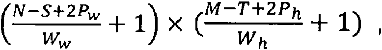
en el que Ww y Wh definen el ancho de avance en la dirección de las líneas y la dirección de las filas, respectivamente. Está claro que sólo se permiten esos rellenos y esos anchos de avance para un determinado núcleo K con tamaño S * T que producen como resultado números enteros para el tamaño de la nueva matriz. Además, los anchos de avance Ww y Wh son preferiblemente más pequeños que S y T, respectivamente, ya que de lo contrario el núcleo se movería sobre la matriz I de manera que algunas líneas o filas de la matriz original quedan fuera en el cálculo de la nueva matriz.where Ww and Wh define the feed width in the direction of the lines and the direction of the rows, respectively. It is clear that only such padding and feed widths are allowed for a given K kernel with size S * T resulting in integers for the size of the new matrix. Furthermore, the feed widths Ww and Wh are preferably smaller than S and T, respectively, since otherwise the nucleus would move on the matrix I such that some lines or rows of the original matrix are left out in the calculation of the new matrix.
Para facilitar la discusión, a continuación se asumirá que no se proporciona un relleno a la matriz original I y que el ancho de avance es igual a 1 para avances horizontales y verticales. Además, se asumirá que el núcleo es una matriz con un tamaño S * S, es decir, el caso especial en el que se asumirá S = T. La aplicación de las explicaciones que se proporcionan a continuación a un relleno y ancho de avance arbitrarios, así como a cualquier tamaño de núcleo es sencilla con la enseñanza que se proporciona a continuación.For ease of discussion, it will be assumed below that no fill is provided to the original matrix I and that the feed width is equal to 1 for horizontal and vertical feeds. Also, the core will be assumed to be a matrix with size S * S, that is, the special case where S = T will be assumed. Applying the explanations given below to arbitrary padding and feed width as well as any size core is straightforward with the teaching provided below.
En la capa convolucional en profundidad 211, la matriz de entrada recibida 230 se utiliza para formar un producto interno con el núcleo K que tiene el tamaño S x S en el que S < N, M. El producto interno se calcula para cada matriz reducida de la matriz original N x M en el que la matriz reducida es de tamaño S x S y contiene entradas coherentes en la matriz original N x M. Por ejemplo, considerando S = 3, la primera matriz reducida R de la matriz original N x M comprende las entradas i = 1, 2, 3; j = 1, 2, 3 de modo que la matriz reducida (N * M)s comprende nueve entradas y se calcula el producto interno con el núcleo K que produce como resultado un único número. La siguiente matriz reducida en las direcciones de las líneas de la matriz original N x M es la matriz en el que i se incrementa en 1, de tal manera que la siguiente matriz en esta dirección está constituida por los elementos de la matriz original N * M en el que i = 2, 3, 4; j = 1, 2, 3. Esta matriz se puede utilizar entonces para calcular el siguiente producto interno con el núcleo. Cabe señalar que el ejemplo proporcionado de la matriz S x S con S = 3 es sólo un ejemplo y que también se pueden utilizar otros núcleos.In the depth convolutional layer 211, the received input matrix 230 is used to form an inner product with the core K having the size S x S where S <N, M. The inner product is calculated for each reduced matrix of the original matrix N x M in which the reduced matrix is of size S x S and contains coherent entries in the original matrix N x M. For example, considering S = 3, the first reduced matrix R of the original matrix N x M comprises the entries i = 1, 2, 3; j = 1, 2, 3 so that the reduced matrix (N * M) s comprises nine entries and the inner product with the kernel K is calculated, resulting in a single number. The next matrix reduced in the directions of the lines of the original matrix N x M is the matrix in which i increases by 1, in such a way that the next matrix in this direction is constituted by the elements of the original matrix N * M where i = 2, 3, 4; j = 1, 2, 3. This matrix can then be used to calculate the next inner product with the nucleus. It should be noted that the provided example of the S x S matrix with S = 3 is just an example and that other kernels can also be used.
Con el fin de calcular la siguiente matriz reducida R de tamaño (N * M)s en la dirección de las filas/columnas, se incrementa en 1 el índice j de elementos en la matriz original N * M. Esto se realiza hasta la última matriz reducida en la dirección de las líneas en que i = N - S 1, N - S 2, N - S 3 en el caso de S = 3. Para las filas, esto se realiza de una correspondiente manera en la que j = M - S 1, M - S 2, M - S 3. Calculando estos productos internos, se calcula una nueva matriz, la matriz P, que tiene el tamaño (N - S 1) * (M - S 1). Sus entradas P¡j corresponden al respectivo producto interno calculado con la correspondiente matriz reducida de la matriz original N * M y el núcleo K. Cabe señalar que una matriz de este tamaño será, efectivamente, suministrada a la capa convolucional punto a punto de la capa 200.In order to calculate the next reduced matrix R of size (N * M) s in the direction of the rows / columns, the index j of elements in the original matrix N * M is increased by 1. This is done until the last matrix reduced in the direction of the lines where i = N - S 1, N - S 2, N - S 3 in the case of S = 3. For the rows, this is done in a corresponding way where j = M - S 1, M - S 2, M - S 3. By calculating these inner products, a new matrix is calculated, the matrix P, which has the size (N - S 1) * (M - S 1). Its inputs Pj correspond to the respective internal product calculated with the corresponding reduced matrix of the original matrix N * M and the kernel K. It should be noted that a matrix of this size will be, indeed, supplied to the point-to-point convolutional layer of the layer 200.
El núcleo K constituye entradas que se obtienen a través de un proceso de aprendizaje con el que se entrena a la red neuronal con el fin de identificar de forma apropiada los objetos deseados. El núcleo K utilizado en la capa 200 de la red neuronal no es necesariamente idéntico en tamaño y entradas a los núcleos utilizados en otras capas de la respectiva red neuronal. Además, las entradas en el núcleo no tienen por qué ser idénticas entre sí, sino que al menos constituyen números mayores que o iguales a 0. Se puede considerar que las entradas representan "pesos" que se obtienen a través del aprendizaje de la red neuronal.The nucleus K constitutes inputs that are obtained through a learning process with which the neural network is trained in order to appropriately identify the desired objects. The core K used in layer 200 of the neural network is not necessarily identical in size and inputs to the nuclei used in other layers of the respective neural network. In addition, the inputs in the nucleus do not have to be identical to each other, but at least constitute numbers greater than or equal to 0. The inputs can be considered to represent "weights" that are obtained through learning the neural network .
El resultado del procesamiento de la matriz 230 por parte de la capa convolucional en profundidad es la matriz 231 que tiene, según se ha explicado anteriormente, un tamaño (N - S 1) * (M - S 1) en el caso de que el núcleo se mueva en avances sobre la matriz original N * M que tienen una distancia de Ai = 1 en la dirección de las líneas Aj = 1 en la dirección de las filas. Sin embargo, en el caso de que esos avances tengan una distancia mayor como Ai = 2 o Ai = 3 (y potencialmente, de forma correspondiente para las filas), la dimensión del resultado 231 cambiará de forma correspondiente según se ha explicado anteriormente. The result of the processing of matrix 230 by the convolutional layer in depth is matrix 231 which has, as explained above, a size (N - S 1) * (M - S 1) in the case that the nucleus move in advances over the original matrix N * M that have a distance of Ai = 1 in the direction of the lines Aj = 1 in the direction of the rows. However, in case those advances have a greater distance such as Ai = 2 or Ai = 3 (and potentially correspondingly for the rows), the dimension of the result 231 will change correspondingly as explained above.
En el procesamiento adicional, este resultado 231 es suministrado al primer normalizador por lotes 212 que sigue en el orden de procesamiento representado con las flechas de la Figura 4 después de la capa convolucional en profundidad 211. El normalizador por lotes intenta normalizar la matriz de resultados 231 recibida. Esto se consigue calculando la suma de cada una de las entradas de la matriz (N - S 1) * (M - S 1) y dividiéndola por el número de entradas de la matriz (N - S 1) * (M - S 1). El valor promedio V de la matriz (N - S 1) * (M - S 1) (denotada como P a continuación, con los correspondientes elementos de matriz Py) se proporciona del siguiente modo:In further processing, this result 231 is fed to the first batch normalizer 212 which follows in the order of processing represented by the arrows in Figure 4 after the depth convolutional layer 211. The batch normalizer attempts to normalize the result matrix 231 received. This is achieved by calculating the sum of each of the matrix entries (N - S 1) * (M - S 1) and dividing it by the number of matrix entries (N - S 1) * (M - S 1 ). The average value V of the matrix (N - S 1) * (M - S 1) (denoted P below, with corresponding matrix elements Py) is given as follows:
V V = = Tiij PijTiij Pij
n ■ mn ■ m
en el que n y m representan el número de líneas y columnas/filas en la matriz N * M o el número de líneas y columnas en la matriz P. Los elementos Pij son las entradas de la matriz P en el que un determinado elemento Pij es el elemento de la matriz en la línea i y la columna j.in which n and m represent the number of lines and columns / rows in the matrix N * M or the number of lines and columns in the matrix P. The elements Pij are the entries of the matrix P in which a certain element Pij is the matrix element on line i and column j.
El normalizador por lotes calcula entonces una matriz reducida P' sustrayendo, de cada entrada Pij de la matriz original, el valor promedio V, de manera que P'ij = Pij - V. De este modo, los valores de la matriz reducida P' son normalizados de manera que se filtran anomalías en una u otra dirección (valores extremadamente grandes o extremadamente pequeños).The batch normalizer then calculates a reduced matrix P 'by subtracting, from each entry Pij of the original matrix, the average value V, so that P'ij = Pij - V. Thus, the values of the reduced matrix P' they are normalized in such a way that anomalies are filtered in one direction or the other (extremely large or extremely small values).
El resultado 232 creado por el primer normalizador por lotes 212 es una matriz que todavía tiene (en el ejemplo de la Figura 4) el tamaño (N - S 1) * (M - S 1) ya que, hasta ahora, no se ha realizado ninguna otra reducción dimensional de la matriz.The result 232 created by the first batch normalizer 212 is a matrix that still has (in the example in Figure 4) the size (N - S 1) * (M - S 1) since, until now, no performed no other dimensional reduction of the matrix.
El resultado 232 se proporciona entonces a la primera unidad lineal rectificada 213 que sigue al primer normalizador por lotes 212.The result 232 is then provided to the first rectified linear unit 213 which follows the first batch normalizer 212.
La unidad lineal rectificada modifica cada entrada de la matriz 232 calculando además nuevas entradas de matriz Pij en las queThe rectified linear unit modifies each entry of the matrix 232 by also calculating new matrix entries Pij in which
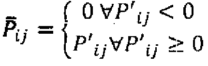
Esto produce como resultado valores que serían menores que 0 después de haber pasado el normalizador por lotes a establecer igual a 0, por lo que no tiene más influencia en el procesamiento adicional en la capa convolucional en profundidad que se explicará a continuación. Esto significa que, por ejemplo, valores de color que están por debajo del valor promedio calculado en el normalizador por lotes ya no se consideran más, y solamente los valores que al menos corresponden al valor promedio V tienen influencia en el resultado de la siguiente etapa del cálculo.This results in values that would be less than 0 after having passed the batch normalizer to set equal to 0, so it has no further influence on further processing in the depth convolutional layer which will be explained below. This means that, for example, color values that are below the average value calculated in the batch normalizer are no longer considered, and only the values that at least correspond to the average value V have influence on the result of the next stage. of the calculation.
El resultado 233 que produce la primera unidad lineal rectificada 213 sigue siendo una matriz de forma/tamaño (N - S 1) * (M - S 1) y esta matriz es suministrada a la capa convolucional punto a punto 221.The result 233 produced by the first rectified linear unit 213 is still a shape / size matrix (N - S 1) * (M - S 1) and this matrix is supplied to the point-to-point convolutional layer 221.
Esta capa convolucional punto a punto 221 crea un resultado 234. Este resultado 234 es creado por la capa convolucional punto a punto 221 tomando cada entrada en la matriz (N - S 1) * (M - S 1) 233 y multiplicando esta entrada por un peso a. a es preferiblemente un número que es mayor que 0 en cualquier caso y este número es idéntico para cada entrada en la matriz (N - S 1) * (M - S 1). El resultado 234 que se obtiene de la capa convolucional punto a punto 221 es, por lo tanto, una matriz que tiene el mismo tamaño (N - S 1) * (M - S 1) pero en la que cada entrada es multiplicada con el peso a.This point-to-point convolutional layer 221 creates a result 234. This result 234 is created by the point-to-point convolutional layer 221 taking each entry in the matrix (N - S 1) * (M - S 1) 233 and multiplying this input by a weight a. a is preferably a number that is greater than 0 in any case and this number is identical for each entry in the matrix (N - S 1) * (M - S 1). The result 234 that is obtained from the point-to-point convolutional layer 221 is, therefore, a matrix that has the same size (N - S 1) * (M - S 1) but in which each input is multiplied with the weight a.
El resultado 234 es proporcionado entonces al segundo normalizador por lotes 222, en el que es normalizado de la manera que se ha explicado para el primer normalizador por lotes 212 y se calcula una matriz normalizada P' de la misma dimensión que el resultado 235, y esta matriz/resultado 235 es suministrado a la segunda unidad lineal rectificada 223, en la que se aplica una función de rectificación para obtener un resultado/matriz P 236 que es suministrado entonces a la siguiente capa de la red neuronal o, si no hay ninguna otra capa siguiente en la red neuronal, el resultado 236 se proporciona como una salida.The result 234 is then provided to the second batch normalizer 222, where it is normalized in the manner explained for the first batch normalizer 212 and a normalized matrix P 'of the same dimension as the result 235 is calculated, and this matrix / result 235 is supplied to the second rectified linear unit 223, in which a rectification function is applied to obtain a result / matrix P 236 which is then supplied to the next layer of the neural network or, if there is no another next layer in the neural network, the result 236 is provided as an output.
En la presente invención se ha descubierto que, para identificar puntas de dedo, lo más apropiado son trece capas que son idénticas a la capa 200 explicada en la Figura 4, ya que producen una precisión de identificación comparativamente alta de las puntas de dedo y su ubicación, al tiempo que sólo se necesitan unos recursos informáticos reducidos para implementar el respectivo procedimiento, lo que lo hace más aplicable a dispositivos móviles.In the present invention it has been discovered that, for identifying fingertips, thirteen layers are most appropriate which are identical to layer 200 explained in Figure 4, since they produce a comparatively high identification precision of the fingertips and their location, while only a small computing resources are needed to implement the respective procedure, which makes it more applicable to mobile devices.
La Figura 5 muestra otra forma de realización según la invención que amplía el concepto descrito en la Figura 4 para permitir una identificación de una punta de dedo (concretamente los píxeles de la imagen original que constituyen la punta de dedo) utilizando una serie de cuadros delimitadores y una disgregación de la imagen original en cuadrículas. Cabe señalar que las etapas que se describen a continuación se pueden realizar después de haber procesado la imagen original en cada capa de la red neuronal o sólo después de que la imagen haya sido procesada en la capa final de la red neuronal, es decir, inmediatamente antes de producir la salida según la etapa 104 de la Figura 3. Figure 5 shows another embodiment according to the invention that extends the concept described in Figure 4 to allow an identification of a fingertip (specifically the pixels of the original image that constitute the fingertip) using a series of bounding boxes and a disintegration of the original image into grids. It should be noted that the steps described below can be performed after having processed the original image in each layer of the neural network or only after the image has been processed in the final layer of the neural network, that is, immediately before producing the output according to step 104 of Figure 3.
La forma de realización que se describe en la Figura 5 asume una red neuronal que ya ha aprendido y que es perfectamente capaz de identificar puntas de dedo u otros objetos con una gran precisión en línea con la invención en base a la salida recibida procedente de una capa de la red neuronal.The embodiment described in Figure 5 assumes a neural network that has already learned and that is perfectly capable of identifying fingertips or other objects with great precision in line with the invention based on the output received from a neural network layer.
De acuerdo con la forma de realización de la Figura 5, se asumirá que la salida recibida procedente de la capa de la red neuronal puede ser todavía representada de alguna manera en la forma de una imagen 300 de una mano 350 que comprende una punta de dedo. De este modo, sólo se hará referencia a "la imagen", aunque es evidente que en lugar de la imagen también se puede utilizar una de las matrices de salida según se explica en la Figura 2.In accordance with the embodiment of Figure 5, it will be assumed that the received output from the neural network layer can still be represented in some way in the form of an image 300 of a hand 350 comprising a fingertip. . In this way, only "the image" will be referred to, although it is clear that instead of the image one of the output matrices can also be used as explained in Figure 2.
En una primera etapa, la imagen 300 recibida es disgregada en una pluralidad de celdas de cuadrícula 310, 311 y 313. El número de celdas de la cuadrícula en cada dirección no está limitado, pero en una forma de realización preferida, la imagen 300 se disgrega en 13 celdas de cuadrícula en dirección horizontal y 13 celdas de cuadrícula en dirección vertical, de manera que en lugar de una cuadrícula general de Q * R se crea una cuadrícula de 13 * 13. In a first step, the received image 300 is broken up into a plurality of grid cells 310, 311 and 313. The number of grid cells in each direction is not limited, but in a preferred embodiment, the image 300 is It breaks down into 13 grid cells in the horizontal direction and 13 grid cells in the vertical direction, so that instead of a general Q * R grid a 13 * 13 grid is created.
En una siguiente etapa, se identifica el punto central 330 de cada celda de la cuadrícula y se utiliza para establecer el origen de un sistema de coordenadas para cada una de las celdas de cuadrícula separada de cualquiera de las otras celdas de la cuadrícula. Alrededor de este centro 330, se dispone al menos un cuadro delimitador 331 y 332 que normalmente tendrá la forma de un rectángulo en el que dichos cuadros tienen, como se puede ver en la celda de cuadrícula 313, una altura inicial h0 y un ancho b0. Para una pluralidad de cuadros delimitadores en cada celda de la cuadrícula, esos valores pueden ser diferentes entre sí. Por ejemplo, se pueden tomar unos valores iniciales h0 y b0 para el cuadro delimitador más pequeño de cada celda de la cuadrícula y se pueden aumentar esos valores en un factor igual a 1,5 o 2 o cualquier otro valor con el fin de calcular las dimensiones de los otros cuadros delimitadores en la respectiva celda de la cuadrícula.In a next step, the center point 330 of each cell in the grid is identified and used to establish the origin of a coordinate system for each of the grid cells separate from any of the other cells in the grid. Around this center 330, at least one bounding box 331 and 332 is arranged which will normally have the shape of a rectangle in which said boxes have, as can be seen in the grid cell 313, an initial height h0 and a width b0 . For a plurality of bounding boxes in each cell of the grid, those values can be different from each other. For example, you can take initial values h0 and b0 for the smallest bounding box in each cell in the grid, and you can increase those values by a factor equal to 1.5 or 2 or any other value in order to calculate the dimensions of the other bounding boxes in the respective grid cell.
Cabe señalar que la posición de un cuadro delimitador, por ejemplo el cuadro delimitador 331 en el sistema de coordenadas de la respectiva celda de la cuadrícula estará representada por la posición del punto central del cuadro delimitador 331 con respecto al punto central 330, es decir, el origen del respectivo sistema de coordenadas, en la respectiva celda de la cuadrícula. De este modo, la posición del respectivo cuadro delimitador en la celda de cuadrícula 311 puede ser representada por dos coordenadas x e y. Se considera que el ancho y la altura del cuadro delimitador representan características geométricas del cuadro delimitador que pueden ser representadas por dos valores mayores que 0.It should be noted that the position of a bounding box, for example the bounding box 331 in the coordinate system of the respective cell of the grid will be represented by the position of the center point of the bounding box 331 with respect to the center point 330, that is, the origin of the respective coordinate system, in the respective cell of the grid. Thus, the position of the respective bounding box in grid cell 311 can be represented by two x and y coordinates. The width and height of the bounding box are considered to represent geometric characteristics of the bounding box that can be represented by two values greater than 0.
Dado que esos cuadros delimitadores se utilizarán más adelante para identificar la posición de una punta de dedo, también es apropiado asociar, con cada uno de esos cuadros delimitadores, un quinto valor que es la probabilidad de que el cuadro delimitador incluya la respectiva punta de dedo que se quiere identificar.Since these bounding boxes will be used later to identify the position of a fingertip, it is also appropriate to associate, with each of these bounding boxes, a fifth value which is the probability that the bounding box includes the respective fingertip that you want to identify.
De este modo, cada cuadro delimitador puede ser representado por un vector de dimensión 5 del siguiente modo Thus, each bounding box can be represented by a vector of dimension 5 as follows
posición-x de cuadro delimitador ^bounding box x-position ^
posición-y de cuadro delimitadorbounding box y-position
b = ancho b de cuadro delimitador b = bounding box width b
altura h de cuadro delimitadorbounding box height h

Esto significa que las celdas de la cuadrícula junto con sus respectivos cuadros delimitadores se pueden representar en forma de un tensor T que tiene las dimensiones Q * R * B * A, en el que A es el número de cuadros delimitadores por celda de cuadrícula. En el caso más preferido para identificar puntas de dedo, Q = R = 13, B = 5 (la dimensión del vector b) y A se puede establecer igual a un número entero entre 3 y 10, más preferiblemente 5.This means that the cells of the grid together with their respective bounding boxes can be represented in the form of a tensor T that has the dimensions Q * R * B * A, where A is the number of bounding boxes per grid cell. In the most preferred case for identifying fingertips, Q = R = 13, B = 5 (the dimension of vector b) and A can be set equal to an integer between 3 and 10, more preferably 5.
Según se ha explicado anteriormente, se asume que la red neuronal ya ha aprendido perfectamente a identificar un objeto específico, preferiblemente una punta de dedo. Esto implica que la red neuronal es capaz de identificar un patrón específico de píxeles que muy probablemente representan una punta de dedo. Esto se podría referir a patrones específicos de valores de color u otras características como el brillo de esos puntos. Sin embargo, está claro que la imagen 300 puede mostrar de forma arbitraria una punta de dedo que podría no corresponder en tamaño y disposición a una punta de dedo que se ha utilizado para el aprendizaje de la red neuronal.As explained above, it is assumed that the neural network has already perfectly learned to identify a specific object, preferably a fingertip. This implies that the neural network is able to identify a specific pattern of pixels that most likely represent a fingertip. This could refer to specific patterns of color values or other characteristics such as the brightness of those points. However, it is clear that image 300 may arbitrarily show a fingertip that might not correspond in size and arrangement to a fingertip that has been used for neural network learning.
Sin embargo, con la ayuda de los cuadros delimitadores y la red, es posible que la red neuronal identifique el cuadro delimitador específico que más probablemente comprenda la punta de dedo. Con el fin de identificar este cuadro delimitador específico, la red neuronal (o un componente asociado que procesa la imagen 300) compara los valores de los píxeles dentro de cada cuadro delimitador de cada celda de la cuadrícula con un patrón de píxeles que corresponde a una punta de dedo, según ha aprendido anteriormente la red neuronal. En esta primera etapa, es muy poco probable que se encuentre una correspondencia perfecta, pero habrá cuadros delimitadores que es más probable que incluyan al menos una parte de una punta de dedo que otros cuadros delimitadores.However, with the help of the bounding boxes and the network, it is possible for the neural network to identify the specific bounding box that the fingertip is most likely to understand. In order to identify this specific bounding box, the neural network (or an associated component that processes image 300) compares the values of the pixels within each bounding box of each cell in the grid with a pixel pattern that corresponds to a fingertip, as the neural network has previously learned. In this first stage, it is very It is unlikely that a perfect match will be found, but there will be bounding boxes that are more likely to include at least part of a fingertip than other bounding boxes.
En el caso representado en la Figura 5, por ejemplo, el cuadro delimitador 341 centrado en el punto M de la celda de cuadrícula 313 incluye una parte de la punta de dedo de la mano 350. En cambio, ninguna de las celdas de cuadrícula 310 y 311 comprende cuadros delimitadores que incluyan una parte de una punta de dedo. Cuando el procedimiento continúa evaluando los valores de píxel dentro del cuadro delimitador 341 y potencialmente del cuadro delimitador 340, el proceso puede determinar que el cuadro delimitador 341 incluye incluso más de un patrón que corresponde a una punta de dedo que el cuadro delimitador 340.In the case depicted in Figure 5, for example, the bounding box 341 centered at point M of the grid cell 313 includes a portion of the fingertip of the hand 350. In contrast, none of the grid cells 310 and 311 comprises bounding boxes that include a portion of a fingertip. As the procedure continues to evaluate the pixel values within the bounding box 341 and potentially the bounding box 340, the process may determine that the bounding box 341 includes even more of a pattern that corresponds to a fingertip than the bounding box 340.
En vista de ello, el procedimiento puede concluir que ninguno de los cuadros delimitadores 331 y 332 (y potencialmente otros cuadros delimitadores en otras celdas de la cuadrícula) incluye una punta de dedo y puede establecer su valor de probabilidad en su correspondiente vector B igual a 0.In light of this, the procedure can conclude that none of bounding boxes 331 and 332 (and potentially other bounding boxes in other cells of the grid) includes a fingertip and can set its probability value to its corresponding vector B equal to 0.
Dado que ambos cuadros delimitadores 340 y 341, centrados en el punto M, comprenden al menos una parte de una punta de dedo, se puede considerar que es probable que comprendan efectivamente una punta de dedo y el valor de probabilidad será superior a 0 en una primera etapa.Since both bounding boxes 340 and 341, centered at point M, comprise at least a part of a fingertip, it can be considered that they are likely to indeed comprise a fingertip and the probability value will be greater than 0 in a first stage.
Si bien la celda de cuadricula más pequeña 340 está casi completamente llena con un patrón que podría corresponder a una punta de dedo, sólo el borde izquierdo de la celda de cuadricula más grande 341 puede ser considerado por el proceso como que incluye un patrón que corresponde a una punta de dedo.While the smaller grid cell 340 is almost completely filled with a pattern that could correspond to a fingertip, only the left edge of the larger grid cell 341 can be considered by the process to include a pattern that corresponds to a fingertip.
Con ello, el procedimiento puede seguir calculando una función de pérdida que determina la diferencia entre el patrón identificado dentro de cada uno de los cuadros delimitadores 341 y 340 con respecto a un patrón obtenido del aprendizaje que corresponde efectivamente a una punta de dedo.With this, the method can continue to calculate a loss function that determines the difference between the pattern identified within each of the bounding boxes 341 and 340 with respect to a pattern obtained from the learning that effectively corresponds to a fingertip.
En la siguiente etapa, el procedimiento intentará minimizar esta diferencia modificando el tamaño y la posición de los respectivos cuadros delimitadores. A este respecto, se puede prever que se utiliza el cuadro delimitador más grande 341 como el punto de partida y se modifica su posición y formas o que se utiliza el cuadro delimitador más pequeño 340 como el punto de partida y se modifica su posición y tamaño con el fin de minimizar las diferencias con respecto al patrón aprendido.In the next stage, the procedure will try to minimize this difference by modifying the size and position of the respective bounding boxes. In this regard, it can be envisaged that the larger bounding box 341 is used as the starting point and its position and shapes are modified or that the smaller bounding box 340 is used as the starting point and its position and size are modified. in order to minimize the differences with respect to the learned pattern.
Este proceso de minimización puede comprender, en primer lugar, modificar la posición del cuadro delimitador (a continuación se asumirá que el cuadro delimitador 341 se utiliza para los cálculos adicionales) moviéndolo una pequeña cantidad en direcciones ortogonales primero a lo largo del eje x y luego a lo largo del eje y (o viceversa), según se muestra en la Figura 3, alrededor del punto central M de la respectiva celda de cuadrícula. El movimiento será a lo largo del eje-x y eje-y positivo y negativo y en cada posición, se realizará una comparación para determinar una función de diferencia entre el patrón obtenido del aprendizaje y el patrón real identificado en la imagen. Esto permite calcular una función bidimensional que representa la diferencia d(x,y) en función de las coordenadas.This minimization process may comprise, first, modifying the position of the bounding box (it will be assumed below that bounding box 341 is used for further calculations) by moving it a small amount in orthogonal directions first along the x-axis and then to along the y-axis (or vice versa), as shown in Figure 3, around the center point M of the respective grid cell. The movement will be along the positive and negative x-axis and y-axis and in each position, a comparison will be made to determine a difference function between the pattern obtained from the learning and the real pattern identified in the image. This allows you to calculate a two-dimensional function that represents the difference d (x, y) as a function of the coordinates.
En base a esto se puede calcular un gradiente Vxyd que permite determinar en qué dirección del sistema de coordenadas hay que mover el cuadro delimitador con el fin de aumentar y, preferiblemente, maximizar la correspondencia con el patrón aprendido (que corresponde a minimizar el valor de la función d(x,y)). Este será el caso para Vxyd = 0.Based on this, a gradient Vxyd can be calculated that allows determining in which direction of the coordinate system the bounding box must be moved in order to increase and, preferably, maximize the correspondence with the learned pattern (which corresponds to minimizing the value of the function d (x, y)). This will be the case for Vxyd = 0.
Esto puede provocar que el cuadro delimitador sea movido a lo largo de la dirección r hacia un nuevo punto central M' en el que la función d(x,y) tiene un mínimo. En una siguiente etapa, se puede aumentar y reducir el tamaño del respectivo cuadro delimitador en la posición M' con el fin de determinar si aumentando o reduciendo el tamaño en una o dos direcciones (es decir, la altura y/o el ancho) cambia el valor de una función de diferencia adicional en comparación con el patrón original que se puede denotar con e(h, b) en función de la altura h y el ancho b. Esta función es minimizada de tal manera que para un cuadro delimitador específico que tiene una posición M' y que tiene una altura hf y un ancho bf, se minimiza la diferencia con el patrón aprendida.This can cause the bounding box to be moved along the direction r to a new center point M 'at which the function d (x, y) has a minimum. In a next step, you can increase and decrease the size of the respective bounding box at position M 'in order to determine whether increasing or decreasing the size in one or two directions (i.e. height and / or width) changes. the value of an additional difference function compared to the original pattern that can be denoted by e (h, b) as a function of height h and width b. This function is minimized in such a way that for a specific bounding box that has a position M 'and that has a height hf and a width bf, the difference with the learned pattern is minimized.
Este cuadro delimitador se utilizará luego como el cuadro delimitador final que tiene la mayor probabilidad p de identificar esas partes de la imagen 300 que contienen la respectiva punta del dedo. El vector de salida de este cuadro delimitador tendrá entonces la siguiente formaThis bounding box will then be used as the final bounding box that has the highest probability p of identifying those parts of the image 300 that contain the respective fingertip. The output vector of this bounding box will then have the following form
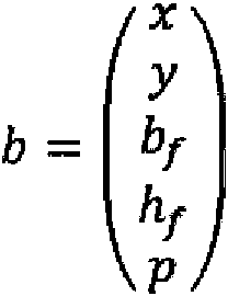
Como resultado de este proceso, se obtiene como salida un tensor T con dimensión Q * R * B * A en el que, para cada cuadro delimitador de cada celda de la cuadrícula, se proporciona la posición x e y con respecto al centro de la celda de cuadrícula, así como el ancho y la altura del respectivo cuadro delimitador y su probabilidad de identificar o comprender una punta de dedo.As a result of this process, a tensor T with dimension Q * R * B * A is obtained as output in which, for each bounding box of each cell of the grid, the x and y position with respect to the center of the grid is given. grid cell, as well as the width and height of the respective bounding box and its probability of identifying or understanding a fingertip.
Con el fin de evitar el movimiento de cuadros delimitadores de una celda de cuadrícula adyacente en la misma dirección de manera que se superpongan entre sí, y con el fin de evitar que cuadros delimitadores de diferentes celdas de cuadrícula se muevan a otras celdas de cuadrícula, el procedimiento se puede proporcionar de manera que el movimiento del centro de un cuadro delimitador sólo sea posible dentro de su celda de cuadrícula original.In order to avoid moving bounding boxes of an adjacent grid cell in the same direction so that they overlap each other, and in order to prevent bounding boxes of different grid cells from moving to other grid cells, the procedure can be provided so that moving the center of a bounding box is only possible within its original grid cell.
El resultado será, de este modo, un tensor que comprende una pluralidad de vectores B en el que uno o más de esos vectores tienen una alta probabilidad de identificar la punta de dedo mientras que otros tienen una baja probabilidad. Los que tienen una baja probabilidad pueden ser ignorados completamente estableciendo todos sus valores correspondientes iguales a 0, reduciendo de este modo el esfuerzo de procesamiento necesario en el procesamiento del tensor.The result will thus be a tensor comprising a plurality of vectors B in which one or more of those vectors have a high probability of identifying the fingertip while others have a low probability. Those with a low probability can be completely ignored by setting all their corresponding values equal to 0, thereby reducing the processing effort required in tensor processing.
A continuación se utilizarán los vectores B de mayor probabilidad con el fin de permitir el procesamiento adicional de la imagen y, en concreto, de las partes de la imagen que identifican la punta de dedo, por ejemplo, con el fin de identificar al usuario del dispositivo móvil procesando la punta del dedo con el fin de identificar la huella dactilar. Next, the B vectors with the highest probability will be used in order to allow further processing of the image and, specifically, of the parts of the image that identify the fingertip, for example, in order to identify the user mobile device processing the fingertip in order to identify the fingerprint.
Si bien el enfoque anterior permite identificar de forma apropiada el cuadro delimitador que se utilizará para procesar adicionalmente la característica biométrica identificada, como una huella dactilar, se proporcionará una explicación más detallada sobre los cuadros delimitadores a descartar.While the above approach allows for the appropriate identification of the bounding box that will be used to further process the identified biometric characteristic, such as a fingerprint, a more detailed explanation will be provided on the bounding boxes to be discarded.
Según se ha explicado anteriormente, el vector b de un cuadro delimitador comprende una probabilidad p que indica la probabilidad de que el respectivo cuadro delimitador incluya o represente una punta de dedo. Esto se puede utilizar para ordenar todos los cuadros delimitadores (o sus vectores, respectivamente) en orden descendente empezando por los vectores b que tienen el valor de probabilidad p más grande.As explained above, the vector b of a bounding box comprises a probability p that indicates the probability that the respective bounding box includes or represents a fingertip. This can be used to sort all bounding boxes (or their vectors, respectively) in descending order starting with the vectors b that have the largest probability value p.
Una vez hecho esto, se puede recorrer la lista en orden descendente empezando por el cuadro delimitador que tiene el valor p más grande. Este recorrido puede incluir seleccionar de la lista un cuadro delimitador específico con valor p y calcular, para este cuadro delimitador específico, la cantidad de intersección con todos los demás cuadros delimitadores. Esto significa que el área del cuadro delimitador específico que se selecciona es comparada con el área de los restantes cuadros delimitadores y cualesquiera áreas que tienen en común (es decir, en la que los cuadros delimitadores intersectan) contribuye a la intersección calculada.Once this is done, the list can be traversed in descending order starting with the bounding box that has the largest p-value. This walkthrough may include selecting a specific p-value bounding box from the list and calculating, for this specific bounding box, the amount of intersection with all other bounding boxes. This means that the specific bounding box area that is selected is compared to the area of the remaining bounding boxes and whatever areas they have in common (that is, where the bounding boxes intersect) contribute to the calculated intersection.
La cantidad de intersección se puede calcular como un ratio con respecto al área del cuadro delimitador seleccionado. De este modo, se obtiene un valor adimensional para cada intersección calculada que va de 0 (sin intersección) a 1 (el cuadro delimitador restante considerado intersecta o cubre completamente el área del cuadro delimitador seleccionado).The amount of intersection can be calculated as a ratio to the area of the selected bounding box. In this way, a dimensionless value is obtained for each calculated intersection ranging from 0 (no intersection) to 1 (the remaining bounding box considered intersects or completely covers the area of the selected bounding box).
En la siguiente etapa, se puede utilizar un umbral preestablecido para ignorar o descartar cuadros delimitadores u ordenarlos. En el ejemplo anterior, el umbral podría ser una intersección calculada igual a 0,75. Por cada par calculado de un cuadro delimitador seleccionado y un cuadro delimitador restante cuya intersección supera este umbral, el cuadro delimitador de valor p más pequeño puede ser ignorado u ordenado en la lista mencionada anteriormente. In the next stage, a preset threshold can be used to ignore or discard bounding boxes or sort them. In the example above, the threshold could be a calculated intercept equal to 0.75. For every calculated pair of a selected bounding box and a remaining bounding box whose intersection exceeds this threshold, the smallest p-value bounding box can be ignored or sorted in the list mentioned above.
Esto finalmente dará lugar a que sólo quede un cuadro delimitador que representará la punta del dedo. Esto puede, por supuesto, dar lugar a hasta cuatro cuadros delimitadores restantes, dependiendo de la cantidad de dedos que son visibles en la imagen.This will ultimately result in only one bounding box remaining representing the fingertip. This can, of course, result in up to four remaining bounding boxes, depending on how many fingers are visible in the image.
En la Figura 6, se explicará ahora cómo se puede entrenar de forma apropiada la red neuronal de manera que los pesos del núcleo K y el peso a explicados con respecto a la Figura 4, así como los patrones que identifican efectivamente una punta de dedo, sean aprendidos por la red neuronal.In Figure 6, it will now be explained how the neural network can be properly trained so that the core weights K and the weight a explained with respect to Figure 4, as well as the patterns that effectively identify a fingertip, are learned by the neural network.
El procedimiento de la Figura 6 comienza con la provisión de datos de entrenamiento 401 y cuadros delimitadores preestablecidos 408. Los datos de entrenamiento pueden estar constituidos por una pluralidad de imágenes de, por ejemplo, puntas de dedo o una pluralidad de dedos representados en una imagen junto con otros objetos. Las imágenes pueden ser multiplicadas utilizando, a partir de la misma imagen, copias rotadas, resaltadas, oscurecidas, ampliadas o modificadas de otra manera que se introducen como datos de entrenamiento. Los cuadros delimitadores proporcionados de acuerdo con el elemento 408 son cuadros delimitadores correspondientes a su respectiva imagen en los datos de entrenamiento, en el que estos cuadros delimitadores son los cuadros delimitadores que están asociados correctamente con el objeto a identificar, es decir, tienen el tamaño correcto y la posición correcta y un valor de probabilidad correspondiente, según se explica con respecto a la Figura 5. Dichos cuadros delimitadores se proporcionan para todas y cada una de las imágenes de los datos de entrenamiento.The procedure of Figure 6 begins with the provision of training data 401 and preset bounding boxes 408. The training data may consist of a plurality of images of, for example, fingertips or a plurality of fingers represented in one image. along with other objects. Images can be multiplied using, from the same image, rotated, highlighted, darkened, enlarged, or otherwise modified copies that are entered as training data. The bounding boxes provided according to item 408 are bounding boxes corresponding to their respective image in the training data, where these bounding boxes are the bounding boxes that are correctly associated with the object to be identified, that is, they have the size correct and correct position and a corresponding probability value, as explained with respect to Figure 5. Such bounding boxes are provided for each and every image in the training data.
En la siguiente etapa, se proporciona una imagen de entrada específica 402 a la red neuronal en un entorno de entrenamiento en el que, además de la red neuronal, se proporciona un optimizador 407 y un calculador de función de pérdida 406. In the next stage, a specific input image 402 is provided to the neural network in a training environment where, in addition to the neural network, an optimizer 407 and a loss function calculator 406 are provided.
La imagen de entrada es procesada, en una primera ronda, utilizando la capa convolucional en profundidad y el primer normalizador por lotes, así como la primera unidad lineal rectificada 403, resumidos como DCBR, y luego es transferida a la capa convolucional punto a punto, al segundo normalizador por lotes y a la segunda unidad lineal rectificada, resumidos como PCBR, en que se procesan de acuerdo con la descripción proporcionada en la Figura 4. Esto significa que las etapas o las secciones 403 y 404 representadas en la Figura 6 son ejecutadas preferiblemente trece veces según se describe con referencia a la Figura 4 utilizando, en cada sección 403 y 404, los correspondientes pesos para la capa convolucional punto a punto (PC) y el núcleo K de la capa convolucional en profundidad (DC). El primer y el segundo normalizadores por lotes, así como las unidades lineales rectificadas de los elementos 403 y 404 funcionan de la manera explicada anteriormente con respecto a la Figura 5.The input image is processed, in a first round, using the depth convolutional layer and the first batch normalizer, as well as the first rectified linear unit 403, summarized as DCBR, and then transferred to the point-to-point convolutional layer, to the second batch normalizer and the second rectified linear unit, summarized as PCBR, in that they are processed according to the description provided in Figure 4. This means that the steps or sections 403 and 404 represented in Figure 6 are preferably executed thirteen times as described with reference to Figure 4 using, in each section 403 and 404, the corresponding weights for the point-to-point convolutional layer (PC) and the core K of the depth convolutional layer (DC). The first and second batch normalizers, as well as the rectified linear units of elements 403 and 404 operate in the manner explained above with respect to Figure 5.
Como resultado, en línea con la Figura 5, la salida será un primer tensor T de tamaño Q * R * B * A con unas primeras entradas Tqrba en línea con la Figura 5. Este resultado será proporcionado a continuación a la función de pérdida, en la que será comparado con los cuadros delimitadores preestablecidos con el fin de identificar las diferencias entre el resultado 405 y los cuadros delimitadores correctos obtenidos de 408. Esta diferencia obtenida por la función de pérdida 406 es proporcionada entonces al optimizador 407 que, a su vez, modificará los pesos de cada capa convolucional punto a punto y cada capa convolucional en profundidad, es decir, a y las entradas en el núcleo K. Esto significa que, ya sea para todas las capas de la red a la vez o para cada capa individualmente, se manipulan el peso a de la capa convolucional punto a punto y las entradas en el núcleo K de la capa convolucional en profundidad. As a result, in line with Figure 5, the output will be a first tensor T of size Q * R * B * A with first inputs Tqrba in line with Figure 5. This result will then be provided to the loss function, in which it will be compared with the preset bounding boxes in order to identify the differences between the result 405 and the correct bounding boxes obtained from 408. This difference obtained by the loss function 406 is then provided to the optimizer 407 which, in turn , it will modify the weights of each convolutional layer point to point and each convolutional layer in depth, that is, a and the inputs in the core K. This means that, either for all layers of the network at once or for each layer individually , the weight a of the point-to-point convolutional layer and the inputs in the core K of the convolutional layer are manipulated in depth.
Con estos nuevos valores, el ciclo se repite para la misma imagen y se proporciona el tensor resultante T' con entradas T'qrba a la función de pérdida y se compara con los cuadros delimitadores correctos, cuyo resultado es proporcionado entonces al optimizador 407 que, una vez más, modifica los pesos.With these new values, the cycle is repeated for the same image and the resulting tensor T 'with inputs T'qrba is provided to the loss function and compared with the correct bounding boxes, the result of which is then provided to optimizer 407 which, once again, modify the weights.
Este procedimiento se realiza siempre que la diferencia entre el tensor T(n) resultante y, específicamente, los cuadros delimitadores identificados en comparación con los cuadros delimitadores predefinidos del elemento 408 superen un determinado umbral que, en esencia, corresponde a la precisión de la identificación que se pretende.This procedure is performed whenever the difference between the resulting tensor T (n) and, specifically, the identified bounding boxes compared to the predefined bounding boxes of element 408 exceed a certain threshold which, in essence, corresponds to the precision of the identification that is intended.
Después de esto, se toma la siguiente imagen de entrada 402 de los datos de entrenamiento 401 y se proporcionan los correspondientes cuadros delimitadores a la función de pérdida. A continuación, el proceso explicado se repite de nuevo para la nueva imagen y se obtienen los pesos óptimos para la capa convolucional punto a punto y la capa convolucional en profundidad. Esto se repite hasta que una combinación específica de pesos provoca una precisión de identificación apropiada para todas las imágenes de entrada. La combinación de pesos que se obtiene entonces es proporcionada como pesos finales 410.After this, the next input image 402 is taken from the training data 401 and the corresponding bounding boxes are provided to the loss function. Then the explained process is repeated again for the new image and the optimal weights for the point-to-point convolutional layer and the depth convolutional layer are obtained. This is repeated until a specific combination of weights causes appropriate identification precision for all input images. The combination of weights that is then obtained is given as final weights 410.
Estos pesos finales son proporcionados entonces a la aplicación que ejecuta el procedimiento inventivo en el dispositivo móvil.These final weights are then provided to the application that executes the inventive procedure on the mobile device.
Por consiguiente, en el concepto de la presente invención, la red neuronal que se proporciona al dispositivo móvil ya está plenamente adaptada para la identificación de objetos específicos que incluyen una característica biométrica, preferiblemente puntas de dedo y, por lo tanto, se puede utilizar sin que se requiera ningún aprendizaje adicional, lo que reduce aún más los recursos informáticos necesarios en los dispositivos móviles.Consequently, in the concept of the present invention, the neural network that is provided to the mobile device is already fully adapted for the identification of specific objects that include a biometric characteristic, preferably fingertips, and can therefore be used without no additional learning is required, further reducing the computing resources required on mobile devices.
En total, utilizando las capas convolucionales punto a punto, las capas convolucionales en profundidad y los normalizadores por lotes, así como las unidades lineales rectificadas según se ha explicado anteriormente con referencia a las Figuras 3 y 4, y utilizando la disgregación de la imagen original en celdas de cuadrícula e identificando los correspondientes cuadros delimitadores en línea con la descripción de la Figura 3, se puede proporcionar una aplicación de menos de un megabyte, lo que permite su utilización en un dispositivo móvil de forma aislada, incluso sin ningún acceso a fuentes de datos adicionales a través de Internet o similares. Esto lo hace adecuado para su aplicación en entornos en los que no es posible el acceso a redes inalámbricas o similares. Además, la potencia del procesador necesaria para ejecutar esta aplicación se reduce al mínimo, a la vez que se obtienen resultados adecuados de identificación de puntas de dedo que se pueden utilizar para la identificación posterior del usuario a través de las huellas dactilares asociadas a las puntas de dedo, según se ha explicado anteriormente.In total, using point-to-point convolutional layers, depth convolutional layers and batch normalizers, as well as rectified linear units as explained above with reference to Figures 3 and 4, and using disintegration of the original image in grid cells and identifying the corresponding bounding boxes in line with the description in Figure 3, an application of less than one megabyte can be provided, allowing it to be used on a mobile device in isolation, even without any access to sources additional data over the Internet or similar. This makes it suitable for application in environments where access to wireless networks or the like is not possible. In addition, the processor power required to run this application is minimized, while obtaining adequate finger tip identification results that can be used for subsequent identification of the user through fingerprints associated with the tips. finger, as explained above.
Las explicaciones anteriores se han centrado en imágenes de una mano o dedos que muestran el lado de los dedos que incluye las huellas. Sin embargo, un usuario también puede presentar por accidente o voluntariamente uno o más dedos del otro lado, es decir, del revés de la mano, al sensor óptico. A partir de dicha imagen de un dedo, no se puede extraer una huella dactilar ya que no es visible.The previous explanations have focused on images of a hand or fingers showing the side of the fingers that includes the footprints. However, a user may also accidentally or voluntarily present one or more fingers on the other side, ie the back of the hand, to the optical sensor. From said image of a finger, a fingerprint cannot be extracted as it is not visible.
Con el fin de distinguir una imagen de una punta de dedo que incluye la huella dactilar con respecto a una imagen de una punta de dedo que no muestra la huella dactilar sino la uña o nudillos, se puede utilizar el siguiente procedimiento que puede ampliar los procedimientos explicados anteriormente para aumentar la precisión de la identificación. In order to distinguish an image of a fingertip that includes the fingerprint from an image of a fingertip that does not show the fingerprint but the fingernail or knuckles, the following procedure can be used that can expand the procedures explained above to increase the accuracy of the identification.
En los ejemplos anteriores, el cuadro delimitador se ha caracterizado por el vector In the previous examples, the bounding box has been characterized by the vector
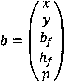
y el entrenamiento se ha realizado usando sólo imágenes de dedos que muestran el lado de las puntas de dedo que incluyen las huellas dactilares.and the training has been done using only finger images showing the side of the fingertips that include the fingerprints.
Cuando se permite que se tomen imágenes de ambos lados de las puntas de dedo (es decir, el lado que incluye la huella dactilar y el lado que incluye la uña o nudillos), es ventajoso considerar dos clases de objetos identificados en las imágenes, a saber, esos objetos que constituyen puntas de dedo que muestran huellas dactilares y esos objetos que constituyen puntas de dedo que muestran uñas o nudillos.When images are allowed of both sides of the fingertips (that is, the side that includes the fingerprint and the side that includes the fingernail or knuckles), it is advantageous to consider two classes of objects identified in the images, a namely, those objects that constitute fingertips that show fingerprints and those objects that constitute fingertips that show fingernails or knuckles.
En este caso, el mencionado vector puede ser ampliado en una dimensión c de modo queIn this case, the mentioned vector can be expanded in a dimension c so that
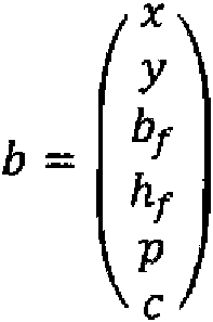
en el que la c representa una denominada clase. Una primera clase puede representar una identificación positiva (se puede identificar una punta de dedo con una huella dactilar) y la segunda clase puede representar una identificación negativa (la punta del dedo incluye una uña o nudillo). La clase puede estar representada por valores, por ejemplo, 1 para una identificación positiva y 0 para una identificación negativa. Es evidente que, a diferencia de los demás valores del vector b, la clase es un valor discreto y sólo puede tomar un número limitado de diferentes valores correspondientes al número de clases.where the c represents a so-called class. A first class can represent a positive identification (a fingertip can be identified with a fingerprint) and the second class can represent a negative identification (the fingertip includes a fingernail or knuckle). The class can be represented by values, for example 1 for a positive identification and 0 for a negative identification. It is clear that, unlike the other values of the vector b, the class is a discrete value and can only take a limited number of different values corresponding to the number of classes.
El entrenamiento mencionado anteriormente se puede realizar entonces de manera que se proporcionan a la red neuronal identificaciones positivas y negativas (en lugar de sólo los datos de entrenamiento que muestran imágenes con puntas de dedo que incluyen huellas dactilares y cuadros delimitadores 408) con el fin de poder distinguir entre imágenes pertenecientes a la primera o a la segunda clase. En este contexto, es posible imaginar una pluralidad de imágenes de dedos que muestran cualquier cosa que no es la huella dactilar. Todos dichos "objetos" se pueden clasificar en la segunda clase (es decir, identificación negativa) de manera que la red neuronal es entrenada para que distinga imágenes de puntas de dedo que incluyen huellas dactilares con respecto a "cualquier otra" imagen de puntas de dedo. Los cuadros delimitadores proporcionados para entrenamiento comprenderán también, por supuesto, la clase c correcta con el fin de permitir un entrenamiento apropiado de la red.The aforementioned training can then be performed in a way that provides the neural network with positive and negative identifications (instead of just the training data showing images with fingertips including fingerprints and bounding boxes 408) in order to be able to distinguish between images belonging to the first or second class. In this context, it is possible to imagine a plurality of finger images showing anything other than the fingerprint. All such "objects" can be classified into the second class (ie negative identification) so that the neural network is trained to distinguish images of fingertips that include fingerprints from "any other" image of finger tips. finger. The bounding boxes provided for training will of course also comprise the correct c-class in order to allow proper training of the network.
Con el fin de identificar todas las puntas de dedo en una imagen que incluyen huellas dactilares, el proceso que se ha descrito anteriormente ignorará todos los cuadros delimitadores que representan la posición de una punta de dedo y que se considera que pertenecen a la segunda clase (es decir, identificación negativa), impidiendo de este modo un procesamiento adicional de imágenes o partes de imágenes de puntas de dedo que no muestran la característica biométrica.In order to identify all the fingertips in an image that include fingerprints, the process described above will ignore all bounding boxes that represent the position of a fingertip and are considered to belong to the second class ( i.e. negative identification), thus preventing further processing of images or parts of images of fingertips that do not display the biometric characteristic.
Con el fin de ofrecer un contexto en el que se puede realizar el procedimiento inventivo, la Figura 7 muestra un dispositivo móvil en forma de teléfono inteligente según una forma de realización de la invención.In order to provide a context in which the inventive method can be performed, Figure 7 shows a mobile device in the form of a smartphone according to an embodiment of the invention.
El dispositivo móvil 500 está representado como un teléfono inteligente según se conoce actualmente. Comprende un sensor óptico 520 preferiblemente en la parte trasera de la cámara que es opuesta al lado del dispositivo móvil 500 en el que se encuentra el visualizador 530. La cámara puede ser una cámara con una resolución de 1MP, 2MP o incluso más, de este modo, por ejemplo, una cámara de alta definición. Puede comprender una linterna, pero no es necesario. También puede estar adaptada para tomar imágenes en tiempo real con una resolución reducida y, una vez activada la cámara, el visualizador 530 puede mostrar una representación de lo que la cámara "ve" realmente. Esto puede ser, por ejemplo, una mano 510.Mobile device 500 is represented as a smartphone as is currently known. It comprises an optical sensor 520 preferably at the rear of the camera that is opposite to the side of the mobile device 500 on which the display 530 is located. The camera can be a camera with a resolution of 1MP, 2MP or even more, of this mode, for example, a high definition camera. You can understand a flashlight, but it is not necessary. It can also be adapted to take real-time images at reduced resolution and, once the camera is activated, the display 530 can display a representation of what the camera actually "sees". This can be, for example, a 510 hand.
En una forma de realización de la invención, una vez que el procedimiento inventivo se ha realizado para una imagen adquirida, los cuadros delimitadores 511 - 514 que identifican las puntas de dedo de la mano son aumentados sobre la imagen de la mano mostrada en el visualizador 530. Según se ha explicado anteriormente, no es necesario mostrar los cuadros delimitadores identificados, sino que también pueden ser procesados adicionalmente internamente en el dispositivo móvil con el fin de, por ejemplo, procesar las partes de la imagen que corresponden a las puntas de dedo de manera que el usuario es identificado mediante identificación de las huellas dactilares asociadas con las puntas de dedo. In an embodiment of the invention, once the inventive procedure has been performed for an acquired image, the bounding boxes 511-514 that identify the fingertips of the hand are enlarged over the image of the hand shown on the display. 530. As explained above, it is not necessary to display the identified bounding boxes, but they can also be further processed internally on the mobile device in order, for example, to process the parts of the image that correspond to the fingertips. so that the user is identified by identifying the fingerprints associated with the fingertips.
Claims (15)

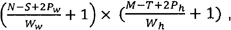
Applications Claiming Priority (2)
| Application Number | Priority Date | Filing Date | Title |
|---|---|---|---|
| EP18206807.2A EP3540633B1 (en) | 2018-03-16 | 2018-03-16 | Method for identifying an object within an image and mobile device for executing the method |
| EP18382174.3A EP3540635B1 (en) | 2018-03-16 | 2018-03-16 | Method for identifying an object within an image and mobile device for executing the method |
Publications (1)
| Publication Number | Publication Date |
|---|---|
| ES2837382T3 true ES2837382T3 (en) | 2021-06-30 |
Family
ID=61768233
Family Applications (2)
| Application Number | Title | Priority Date | Filing Date |
|---|---|---|---|
| ES18206807T Active ES2837382T3 (en) | 2018-03-16 | 2018-03-16 | Procedure to identify an object within an image and mobile device to execute the procedure |
| ES18382174T Active ES2828358T3 (en) | 2018-03-16 | 2018-03-16 | Procedure to identify an object within an image and mobile device to execute the procedure |
Family Applications After (1)
| Application Number | Title | Priority Date | Filing Date |
|---|---|---|---|
| ES18382174T Active ES2828358T3 (en) | 2018-03-16 | 2018-03-16 | Procedure to identify an object within an image and mobile device to execute the procedure |
Country Status (13)
| Country | Link |
|---|---|
| US (4) | US11508184B2 (en) |
| EP (3) | EP3540635B1 (en) |
| JP (2) | JP7386545B2 (en) |
| KR (4) | KR102554724B1 (en) |
| CN (1) | CN111989689B (en) |
| AU (2) | AU2019234110B2 (en) |
| BR (2) | BR112020018915A2 (en) |
| CA (3) | CA3093966C (en) |
| ES (2) | ES2837382T3 (en) |
| MX (3) | MX2020009382A (en) |
| PE (3) | PE20201181A1 (en) |
| WO (2) | WO2019175846A1 (en) |
| ZA (2) | ZA202006256B (en) |
Families Citing this family (20)
| Publication number | Priority date | Publication date | Assignee | Title |
|---|---|---|---|---|
| ES2837382T3 (en) * | 2018-03-16 | 2021-06-30 | Identy Inc | Procedure to identify an object within an image and mobile device to execute the procedure |
| WO2020051776A1 (en) * | 2018-09-11 | 2020-03-19 | Intel Corporation | Method and system of deep supervision object detection for reducing resource usage |
| EP3702958B1 (en) * | 2019-02-26 | 2023-04-05 | Identy Inc. | Method for verifying the identity of a user by identifying an object within an image that has a biometric characteristic of the user and separating a portion of the image comprising the biometric characteristic from other portions of the image |
| US11189028B1 (en) * | 2020-05-15 | 2021-11-30 | Retrace Labs | AI platform for pixel spacing, distance, and volumetric predictions from dental images |
| EP4097632B1 (en) * | 2020-01-28 | 2025-04-30 | Universidad Autónoma de Madrid | Method to generate training data for a bot detector module, bot detector module trained from training data generated by the method and bot detection system |
| EP4246454A3 (en) | 2020-04-09 | 2023-11-29 | Identy Inc. | Liveliness detection using a device comprising an illumination source |
| CN111598110B (en) * | 2020-05-11 | 2023-04-28 | 重庆大学 | HOG algorithm image recognition method based on grid cell memory |
| KR20210149542A (en) * | 2020-06-02 | 2021-12-09 | 삼성에스디에스 주식회사 | Method for photographing and reading an image, and apparatus therefor |
| US20220222466A1 (en) | 2021-01-13 | 2022-07-14 | Ford Global Technologies, Llc | Material spectroscopy |
| US11657589B2 (en) | 2021-01-13 | 2023-05-23 | Ford Global Technologies, Llc | Material spectroscopy |
| US11443527B2 (en) | 2021-01-13 | 2022-09-13 | Ford Global Technologies, Llc | Material spectroscopy |
| US11741747B2 (en) | 2021-01-13 | 2023-08-29 | Ford Global Technologies, Llc | Material spectroscopy |
| KR102672353B1 (en) * | 2021-01-25 | 2024-06-05 | 숭실대학교산학협력단 | Apparatus and method for graffiti drawing based on photography |
| WO2023272604A1 (en) * | 2021-06-30 | 2023-01-05 | 东莞市小精灵教育软件有限公司 | Positioning method and apparatus based on biometric recognition |
| CN113449652A (en) * | 2021-06-30 | 2021-09-28 | 东莞市小精灵教育软件有限公司 | Positioning method and device based on biological feature recognition |
| CN113706647B (en) * | 2021-07-30 | 2024-02-13 | 浪潮电子信息产业股份有限公司 | Image coloring method and related device |
| US12223764B2 (en) * | 2022-02-28 | 2025-02-11 | Armatura Llc | System and method for rotation invariant fingerprint recognition |
| CN117037221B (en) * | 2023-10-08 | 2023-12-29 | 腾讯科技(深圳)有限公司 | Living body detection method, living body detection device, computer equipment and storage medium |
| JPWO2025141668A1 (en) * | 2023-12-25 | 2025-07-03 | ||
| EP4657388A1 (en) | 2024-05-28 | 2025-12-03 | Identy Inc. | Computer-implemented method for jointly training at least two different spoof-detection systems |
Family Cites Families (32)
| Publication number | Priority date | Publication date | Assignee | Title |
|---|---|---|---|---|
| US5978495A (en) * | 1996-07-17 | 1999-11-02 | Intelnet Inc. | Method and apparatus for accurate determination of the identity of human beings |
| US6072891A (en) * | 1997-02-21 | 2000-06-06 | Dew Engineering And Development Limited | Method of gathering biometric information |
| JP4085470B2 (en) | 1998-05-29 | 2008-05-14 | オムロン株式会社 | Personal identification device, personal identification method, and recording medium recording personal identification program |
| FR2826443B1 (en) * | 2001-06-21 | 2003-10-10 | Gilles Cavallucci | METHOD AND DEVICE FOR OPTICALLY DETECTING THE POSITION OF AN OBJECT |
| JP4734980B2 (en) | 2005-03-15 | 2011-07-27 | オムロン株式会社 | Face authentication device and control method therefor, electronic device equipped with face authentication device, face authentication device control program, and recording medium recording the program |
| US8542928B2 (en) * | 2005-09-26 | 2013-09-24 | Canon Kabushiki Kaisha | Information processing apparatus and control method therefor |
| KR101349892B1 (en) * | 2006-07-19 | 2014-01-13 | 루미다임 인크. | Multibiometric multispectral imager |
| JP2008257327A (en) | 2007-04-02 | 2008-10-23 | Omron Corp | Verification device |
| US20140068740A1 (en) * | 2012-09-05 | 2014-03-06 | Element, Inc. | System and method for biometric authentication in connection with camera equipped devices |
| JP6304999B2 (en) * | 2013-10-09 | 2018-04-04 | アイシン精機株式会社 | Face detection apparatus, method and program |
| JP6187817B2 (en) * | 2013-10-09 | 2017-08-30 | アイシン精機株式会社 | Face detection apparatus, method and program |
| US10025915B2 (en) * | 2013-12-05 | 2018-07-17 | Lenovo (Singapore) Pte. Ltd. | Contact signature authentication of user of device |
| CA2939637A1 (en) * | 2014-02-12 | 2015-08-20 | Advanced Optical Systems, Inc. | On-the-go touchless fingerprint scanner |
| US9195879B1 (en) * | 2014-08-31 | 2015-11-24 | Qualcomm Incorporated | Air/object determination for biometric sensors |
| KR102290892B1 (en) * | 2014-12-12 | 2021-08-19 | 엘지전자 주식회사 | Mobile terminal and method for controlling the same |
| US11120478B2 (en) | 2015-01-12 | 2021-09-14 | Ebay Inc. | Joint-based item recognition |
| US9424458B1 (en) | 2015-02-06 | 2016-08-23 | Hoyos Labs Ip Ltd. | Systems and methods for performing fingerprint based user authentication using imagery captured using mobile devices |
| US10339362B2 (en) * | 2016-12-08 | 2019-07-02 | Veridium Ip Limited | Systems and methods for performing fingerprint based user authentication using imagery captured using mobile devices |
| SG10201906574VA (en) * | 2015-06-16 | 2019-09-27 | Eyeverify Inc | Systems and methods for spoof detection and liveness analysis |
| KR102439938B1 (en) | 2015-08-03 | 2022-09-05 | 삼성전자주식회사 | Multi-modal fusion method for user authentification and user authentification method |
| JP6952713B2 (en) | 2016-01-19 | 2021-10-20 | マジック リープ, インコーポレイテッドMagic Leap,Inc. | Augmented reality systems and methods that utilize reflection |
| CN106056095A (en) * | 2016-06-13 | 2016-10-26 | 北京小米移动软件有限公司 | Fingerprint processing method and device |
| KR102483642B1 (en) | 2016-08-23 | 2023-01-02 | 삼성전자주식회사 | Method and apparatus for liveness test |
| US11157814B2 (en) * | 2016-11-15 | 2021-10-26 | Google Llc | Efficient convolutional neural networks and techniques to reduce associated computational costs |
| WO2018106987A1 (en) | 2016-12-08 | 2018-06-14 | Veridium Ip Limited | Systems and methods for performing fingerprint based user authentication using imagery captured using mobile devices |
| US10216977B2 (en) * | 2017-01-06 | 2019-02-26 | Qualcomm Incorporated | Progressive multiple fingerprint enrollment and matching, and dynamic user account transitions |
| ES2837382T3 (en) | 2018-03-16 | 2021-06-30 | Identy Inc | Procedure to identify an object within an image and mobile device to execute the procedure |
| CN108810616B (en) * | 2018-05-31 | 2019-06-14 | 广州虎牙信息科技有限公司 | Object localization method, image display method, device, equipment and storage medium |
| CN109145743A (en) * | 2018-07-19 | 2019-01-04 | 叶涵 | A kind of image-recognizing method and device based on deep learning |
| JP7130905B2 (en) * | 2019-06-18 | 2022-09-06 | ユーエービー “ニューロテクノロジー” | Fast and Robust Dermatoglyphic Mark Minutia Extraction Using Feedforward Convolutional Neural Networks |
| EP4361941A1 (en) * | 2022-10-27 | 2024-05-01 | Carl Zeiss Meditec AG | Method, processor unit and system for processing of images |
| CN116486074B (en) * | 2023-03-30 | 2025-08-22 | 浙江工业大学 | A medical image segmentation method based on local and global context information encoding |
-
2018
- 2018-03-16 ES ES18206807T patent/ES2837382T3/en active Active
- 2018-03-16 EP EP18382174.3A patent/EP3540635B1/en active Active
- 2018-03-16 ES ES18382174T patent/ES2828358T3/en active Active
- 2018-03-16 EP EP18206807.2A patent/EP3540633B1/en active Active
- 2018-04-27 EP EP18382295.6A patent/EP3540636A1/en not_active Ceased
-
2019
- 2019-03-15 WO PCT/IB2019/052126 patent/WO2019175846A1/en not_active Ceased
- 2019-03-15 CN CN201980019837.1A patent/CN111989689B/en active Active
- 2019-03-15 US US16/981,262 patent/US11508184B2/en active Active
- 2019-03-15 BR BR112020018915-4A patent/BR112020018915A2/en unknown
- 2019-03-15 CA CA3093966A patent/CA3093966C/en active Active
- 2019-03-15 PE PE2020001377A patent/PE20201181A1/en unknown
- 2019-03-15 AU AU2019234110A patent/AU2019234110B2/en active Active
- 2019-03-15 KR KR1020207029856A patent/KR102554724B1/en active Active
- 2019-03-15 MX MX2020009382A patent/MX2020009382A/en unknown
- 2019-03-15 PE PE2023003138A patent/PE20250719A1/en unknown
- 2019-03-15 PE PE2023002278A patent/PE20240541A1/en unknown
- 2019-03-15 CA CA3215158A patent/CA3215158A1/en active Pending
- 2019-03-15 JP JP2020571920A patent/JP7386545B2/en active Active
- 2019-03-15 KR KR1020237022979A patent/KR20230107415A/en not_active Ceased
- 2019-05-09 KR KR1020227030334A patent/KR102629380B1/en active Active
- 2019-05-09 US US17/050,184 patent/US11495050B2/en active Active
- 2019-05-09 CA CA3098286A patent/CA3098286C/en active Active
- 2019-05-09 MX MX2020011313A patent/MX2020011313A/en unknown
- 2019-05-09 WO PCT/IB2019/053824 patent/WO2019207557A1/en not_active Ceased
- 2019-05-09 KR KR1020207034340A patent/KR102442844B1/en active Active
- 2019-05-09 JP JP2020560255A patent/JP7304082B2/en active Active
- 2019-05-09 BR BR112020021946-0A patent/BR112020021946A2/en unknown
-
2020
- 2020-09-09 MX MX2024003152A patent/MX2024003152A/en unknown
- 2020-10-08 ZA ZA2020/06256A patent/ZA202006256B/en unknown
- 2020-11-26 ZA ZA2020/07383A patent/ZA202007383B/en unknown
-
2022
- 2022-04-28 AU AU2022202817A patent/AU2022202817B2/en active Active
- 2022-06-28 US US17/851,381 patent/US12087078B2/en active Active
- 2022-09-19 US US17/948,029 patent/US12106597B2/en active Active
Also Published As
Similar Documents
| Publication | Publication Date | Title |
|---|---|---|
| ES2837382T3 (en) | Procedure to identify an object within an image and mobile device to execute the procedure | |
| US11113586B2 (en) | Method and electronic device for retrieving an image and computer readable storage medium | |
| Liu et al. | Matching-cnn meets knn: Quasi-parametric human parsing | |
| Miah et al. | Rotation, Translation and Scale Invariant Sign Word Recognition Using Deep Learning. | |
| Tang et al. | A real-time hand posture recognition system using deep neural networks | |
| US11068701B2 (en) | Apparatus and method for vehicle driver recognition and applications of same | |
| US20190303650A1 (en) | Automatic object recognition method and system thereof, shopping device and storage medium | |
| CN115427982A (en) | Methods, systems, and media for identifying human behavior in digital video using convolutional neural networks | |
| Jiang et al. | A survey on artificial intelligence in posture recognition | |
| ES2943287T3 (en) | Method of verifying the identity of a user by identifying an object within an image that has a biometric characteristic of the user and separating a portion of the image comprising the biometric characteristic from other portions of the image | |
| Jeong et al. | Driver facial landmark detection in real driving situations | |
| Strezoski et al. | Hand gesture recognition using deep convolutional neural networks | |
| US20180300591A1 (en) | Depth-value classification using forests | |
| Pishchulin et al. | Image warping for face recognition: From local optimality towards global optimization | |
| Yang et al. | Ddanet: Dual-path depth-aware attention network for fingerspelling recognition using rgb-d images | |
| Ng et al. | Pedestrian gender classification using combined global and local parts-based convolutional neural networks | |
| Pogorelov et al. | A comparison of deep learning with global features for gastrointestinal disease detection | |
| Ahmed et al. | Eye center localization using gradient and intensity information under uncontrolled environment | |
| Shaban et al. | An information fusion framework for person localization via body pose in spectator crowds | |
| Nowosielski et al. | Touchless typing with head movements captured in thermal spectrum | |
| BR112021014579A2 (en) | USER IDENTIFICATION METHOD BY BIOMETRIC CHARACTERISTICS AND MOBILE DEVICE | |
| Bong et al. | Face recognition and detection using haars features with template matching algorithm | |
| Ke et al. | SRN: Side-output residual network for object reflection symmetry detection and beyond | |
| KR20250099768A (en) | System and method for identifying a person in a video | |
| Hlavac | Lips landmark detection using CNN |