EP4467072A1 - Ergospirometry device and corresponding manufacturing method - Google Patents
Ergospirometry device and corresponding manufacturing method Download PDFInfo
- Publication number
- EP4467072A1 EP4467072A1 EP24178157.4A EP24178157A EP4467072A1 EP 4467072 A1 EP4467072 A1 EP 4467072A1 EP 24178157 A EP24178157 A EP 24178157A EP 4467072 A1 EP4467072 A1 EP 4467072A1
- Authority
- EP
- European Patent Office
- Prior art keywords
- ergospirometry
- sensor
- respiratory gas
- measuring device
- parameters
- Prior art date
- Legal status (The legal status is an assumption and is not a legal conclusion. Google has not performed a legal analysis and makes no representation as to the accuracy of the status listed.)
- Pending
Links
Images


Classifications
-
- A—HUMAN NECESSITIES
- A61—MEDICAL OR VETERINARY SCIENCE; HYGIENE
- A61B—DIAGNOSIS; SURGERY; IDENTIFICATION
- A61B5/00—Measuring for diagnostic purposes; Identification of persons
- A61B5/08—Measuring devices for evaluating the respiratory organs
- A61B5/097—Devices for facilitating collection of breath or for directing breath into or through measuring devices
-
- A—HUMAN NECESSITIES
- A61—MEDICAL OR VETERINARY SCIENCE; HYGIENE
- A61B—DIAGNOSIS; SURGERY; IDENTIFICATION
- A61B5/00—Measuring for diagnostic purposes; Identification of persons
- A61B5/08—Measuring devices for evaluating the respiratory organs
- A61B5/083—Measuring rate of metabolism by using breath test, e.g. measuring rate of oxygen consumption
- A61B5/0836—Measuring rate of CO2 production
-
- A—HUMAN NECESSITIES
- A61—MEDICAL OR VETERINARY SCIENCE; HYGIENE
- A61B—DIAGNOSIS; SURGERY; IDENTIFICATION
- A61B5/00—Measuring for diagnostic purposes; Identification of persons
- A61B5/08—Measuring devices for evaluating the respiratory organs
- A61B5/087—Measuring breath flow
- A61B5/0873—Measuring breath flow using optical means
-
- A—HUMAN NECESSITIES
- A61—MEDICAL OR VETERINARY SCIENCE; HYGIENE
- A61B—DIAGNOSIS; SURGERY; IDENTIFICATION
- A61B5/00—Measuring for diagnostic purposes; Identification of persons
- A61B5/22—Ergometry; Measuring muscular strength or the force of a muscular blow
- A61B5/221—Ergometry, e.g. by using bicycle type apparatus
- A61B5/222—Ergometry, e.g. by using bicycle type apparatus combined with detection or measurement of physiological parameters, e.g. heart rate
-
- G—PHYSICS
- G01—MEASURING; TESTING
- G01N—INVESTIGATING OR ANALYSING MATERIALS BY DETERMINING THEIR CHEMICAL OR PHYSICAL PROPERTIES
- G01N21/00—Investigating or analysing materials by the use of optical means, i.e. using sub-millimetre waves, infrared, visible or ultraviolet light
- G01N21/62—Systems in which the material investigated is excited whereby it emits light or causes a change in wavelength of the incident light
- G01N21/63—Systems in which the material investigated is excited whereby it emits light or causes a change in wavelength of the incident light optically excited
- G01N21/64—Fluorescence; Phosphorescence
- G01N21/6408—Fluorescence; Phosphorescence with measurement of decay time, time resolved fluorescence
-
- G—PHYSICS
- G01—MEASURING; TESTING
- G01N—INVESTIGATING OR ANALYSING MATERIALS BY DETERMINING THEIR CHEMICAL OR PHYSICAL PROPERTIES
- G01N21/00—Investigating or analysing materials by the use of optical means, i.e. using sub-millimetre waves, infrared, visible or ultraviolet light
- G01N21/62—Systems in which the material investigated is excited whereby it emits light or causes a change in wavelength of the incident light
- G01N21/63—Systems in which the material investigated is excited whereby it emits light or causes a change in wavelength of the incident light optically excited
- G01N21/64—Fluorescence; Phosphorescence
- G01N21/6428—Measuring fluorescence of fluorescent products of reactions or of fluorochrome labelled reactive substances, e.g. measuring quenching effects, using measuring "optrodes"
-
- G—PHYSICS
- G01—MEASURING; TESTING
- G01N—INVESTIGATING OR ANALYSING MATERIALS BY DETERMINING THEIR CHEMICAL OR PHYSICAL PROPERTIES
- G01N33/00—Investigating or analysing materials by specific methods not covered by groups G01N1/00 - G01N31/00
- G01N33/0004—Gaseous mixtures, e.g. polluted air
- G01N33/0009—General constructional details of gas analysers, e.g. portable test equipment
- G01N33/0027—General constructional details of gas analysers, e.g. portable test equipment concerning the detector
- G01N33/0036—General constructional details of gas analysers, e.g. portable test equipment concerning the detector specially adapted to detect a particular component
- G01N33/004—CO or CO2
-
- G—PHYSICS
- G01—MEASURING; TESTING
- G01N—INVESTIGATING OR ANALYSING MATERIALS BY DETERMINING THEIR CHEMICAL OR PHYSICAL PROPERTIES
- G01N33/00—Investigating or analysing materials by specific methods not covered by groups G01N1/00 - G01N31/00
- G01N33/48—Biological material, e.g. blood, urine; Haemocytometers
- G01N33/483—Physical analysis of biological material
- G01N33/497—Physical analysis of biological material of gaseous biological material, e.g. breath
Definitions
- the present invention relates to an ergospirometry device for detecting parameters of a respiratory gas such as the oxygen concentration (in particular the dioxygen concentration/O 2 concentration/molecular oxygen concentration) and/or the carbon dioxide concentration (CO 2 concentration) and a corresponding manufacturing method.
- a respiratory gas such as the oxygen concentration (in particular the dioxygen concentration/O 2 concentration/molecular oxygen concentration) and/or the carbon dioxide concentration (CO 2 concentration) and a corresponding manufacturing method.
- ergospirometry An alternative name for ergospirometry is spiroergometry.
- ergospirometry from ⁇ ov ("ergon") ancient Greek for "work” or “work”, spirare Latin for "breathe” and ⁇ ov (“metron”) ancient Greek for “measure”
- respiratory gases are measured during physical exertion.
- a minute ventilation volume (or more generally a respiratory time volume) can be measured.
- the carbon dioxide and/or (di)oxygen concentration in the respiratory gas can be measured.
- Mobile ergospirometry devices e.g. for stress tests on humans, have been known for several years. Such systems can be used to carry out analyses directly at the sports facility or workplace under natural conditions and stress situations. Telemetry units transmit measurement data in real time to a personal computer or notebook, making it possible to control the training or exercise process after evaluating the data on the personal computer. Such devices have opened up new areas of application in performance diagnostics in occupational, sports and rehabilitation medicine.
- An ergospirometry system is, for example, from the DE 199 60 257 C1
- an ergospirometry system for animals such as camels or horses.
- the values are determined using the mixing chamber or breath-by-breath principle using funnel-shaped or cylindrical breathing gas masks and gas volume flow or quantity sensors, as well as a measuring unit with sensors for determining the carbon dioxide or dioxygen concentration in the breathing gas, and are then transmitted to a base station via signal transmission means for further processing, display and analysis of the measured values.
- Ultrasonic transducers are provided for determining the volume flow.
- the DE 199 53 866 B4 relates to a mobile ergospirometry system with a measuring unit that can be fixed to the test subject and includes gas volume and quantity sensors for determining the carbon dioxide/dioxygen concentration in the respiratory gas.
- Information or requests for operating the measuring unit and/or for designing the test run can be transmitted online from the base station to the test subject via a signal processing processor and a telemetry module as well as a computer-assisted base station with a telemetry unit for establishing a wireless connection with the telemetry module.
- the DE 10 2016 214 702 A1 describes a device for detecting parameters of a respiratory gas, which has an energy storage device.
- Ergospirometry devices often work according to a so-called mixed chamber principle, i.e. these devices collect the exhaled air from several breaths in one chamber and carry out the respiratory gas measurement in this chamber.
- Modern ergospirometry devices determine the respiratory gas parameters according to a breath-by-breath principle, i.e. these ergospirometry devices can determine the respiratory gas parameters for each breath.
- An object of the present invention is to provide an improved ergospirometry device which is particularly suitable for the parameters of the breathing gas, in particular the concentration of oxygen and/or the concentration of carbon dioxide, has a significantly higher sensitivity and a high speed of evaluation.
- the ergospirometry device can have: a base body that has a breathing mask or a mouthpiece and a respiratory gas guide section, and a measuring device for detecting parameters of the respiratory gas, which can have a computing unit for processing the detected parameters of the respiratory gas, wherein the parameters of the respiratory gas can include at least an oxygen concentration and/or a carbon dioxide concentration in the respiratory gas.
- the measuring device can have at least one optical oxygen sensor for detecting the oxygen concentration of the respiratory gas and/or an optical carbon dioxide sensor (or infrared carbon dioxide sensor), and the detection of the oxygen concentration can be based on a principle of luminescence quenching and/or a principle of dual emission.
- the measuring device can be designed to detect the oxygen concentration via a lifetime evaluation (e.g. the luminescence or physical lifetime of a luminescence decay curve) by assigning the measured lifetime to the oxygen concentration.
- a lifetime evaluation e.g. the luminescence or physical lifetime of a luminescence decay curve
- the lifetime can be determined from two intensities that are detected at times t1 and t2 during the decay.
- the lifetime can be determined using the RLD method.
- the Rapid Lifetime Determination (RLD) method enables the lifetime of fluorescence signals to be determined quickly by Evaluation of the change in the fluorescence signal after a short excitation pulse, typically 10 to 100 ns.
- the lifetime of the fluorescence is described by an exponential function and can be determined by fast data acquisition and processing in real time.
- the lifetime can be determined by phase modulation. With phase modulation, the lifetime is determined via the tangent of the phase shift divided by the excitation frequency.
- the lifetime can be determined by detecting the decay dynamics.
- the quencher concentration can be assigned to the measured lifetime.
- This principle can also be used to calculate the lifetime pixel by pixel, e.g. using one (or more) CCD area sensors, and a concentration of molecular oxygen can be determined pixel by pixel.
- the measuring device can be designed to carry out the lifetime evaluation via a detection of the decay dynamics, via a rapid lifetime determination, RLD, and/or via a phase modulation.
- the measuring device can be designed to detect the oxygen concentration via an evaluation of the quantum yield and/or the intensity.
- the measuring device can be designed for the ratiometric determination of the oxygen concentration and can determine the oxygen concentration from an intensity ratio of the fluorescence and phosphorescence.
- the oxygen sensor can be based on the principle of luminescence quenching with metal complexes (in particular Transition metal complexes), whereby the transition metal complexes can preferably comprise platinum and/or copper.
- the excitation is carried out with a narrow-band LED, whereby the photodetector is provided with simple optics at a short distance. At a greater distance, lens systems can be used. In the case of ambient light interference, a bandpass filter can also be used.
- a dual emission can be possible by varying the metal complex and excitation energy, preferably in the ranges 375 - 445 nm and 450 - 650 nm, in order to derive information about pressure and/or temperature.
- the senor can also function via solids that are not fluorescent and that are transparent, in particular glass, PC (polycarbonate), PMMA (polymethyl methacrylate, also called acrylic glass), PET (polyethylene terephthalate).
- PC polycarbonate
- PMMA polymethyl methacrylate, also called acrylic glass
- PET polyethylene terephthalate
- a small measuring volume has the advantage that the breathing air can be exchanged quickly and that breathing can be followed with only a short time delay (dead time) and high temporal resolution of the measured values.
- a small measuring volume represents a challenge for the sensor design, since the sensor components and electronic components must be accommodated in the small volume.
- a measuring volume of fractions of one milliliter (ml) to a few milliliters is sufficient for a correct measurement.
- the measuring volume can be less than or equal to 0.6 milliliters, in particular between 0.4 and 0.6 milliliters, in particular approximately 0.5 milliliters.
- the measuring volume can also be less than 0.5 milliliters.
- the oxygen sensor can be temperature and barometrically compensated.
- a dual emission with two different wavelengths can be measured (2 excited states).
- the measuring device can also have an integrated pressure sensor Additionally or alternatively, the pressure can also be derived from optical measurements.
- a sensor layer of the oxygen sensor can have a diffusion constant such that it is possible to record a measured value with a time of less than 5 seconds, and particularly preferably less than 0.1 s.
- a dynamic of the sensor is determined over a time t10-t90, i.e. over the time that a sensor signal requires to increase from 10% to 90% of the final value. This has the advantage that dirt effects from supply lines and the like are excluded.
- a carrier material of the sensor layer can comprise a transparent polyester layer or polyester film, which preferably has a layer thickness of less than 800 ⁇ m, and the sensor layer can preferably be a sensor spot for contactless measurement.
- a carrier material is not absolutely necessary.
- a metal complex can be applied directly (to the inside of the breathing gas guide section).
- the measuring device has a sensor spot.
- an excitation light of the excitation diode of the oxygen sensor can flash.
- an excitation light of the excitation diode of the oxygen sensor can have an excitation frequency of more than 1 Hz, particularly preferably between 10 Hz and 100 kHz.
- the light reflected by the sensor layer, in particular the sensor spot can be in the range of 450 - 650 nm and/or 375 - 445 nm.
- the measuring device can be provided on the base body so that the parameters can be recorded directly in a respiratory gas stream that is guided through the base body.
- the parameters of the respiratory gas can be recorded in situ and/or in extraction.
- At least parts of the measuring device can be spaced from the base body so that the parameters of the respiratory gas in extraction can be recorded.
- the carbon dioxide sensor can be provided for detecting a carbon dioxide concentration in the respiratory gas, wherein the detection of the carbon dioxide concentration in the respiratory gas can be based on a detection principle of a non-dispersive infrared sensor, NDIR principle.
- the carbon dioxide sensor can have a photodetector and a light-emitting diode, in particular MIR-LED, for a wavelength range in the mid-infrared range.
- this wavelength range can be between 3 ⁇ m and 8 ⁇ m and particularly preferably between 4.1 ⁇ m and 4.4 ⁇ m.
- the light-emitting diode can be modulated for a wavelength range in the mid-infrared such that clock frequencies of at least 100 kHz are achieved.
- the photodetector may be a quantum well infrared photodetector (QWIP).
- QWIP quantum well infrared photodetector
- the light-emitting diode can comprise a MIR-LED with a reflector so that a very high beam quality is achieved.
- the photodetector can be designed with two channels, so that an evaluation of a reference signal for monitoring the radiator is possible.
- the base body can provide the breathing gas guide section for guiding the breathing gas flow with a subject-side breathing gas inlet and a have a breathing gas outlet and the oxygen sensor must be provided in the breathing gas guide section.
- the ergospirometry device can be a mobile ergospirometry device.
- the ergospirometry device can be at least partially, preferably entirely, resistant to condensation, so that the ergospirometry device is capable of detecting the parameters of the respiratory gas even in liquids.
- the measuring device can have a sensitivity of up to a few ppb and/or a very high dynamic range of up to 100%, up to 9 orders of magnitude.
- the sensor device can be self-referencing.
- the measuring device can have a response time of less than or equal to 0.1 s.
- a manufacturing method of an ergospirometry device for recording parameters of a respiratory gas comprising the following steps: providing a measuring device for recording parameters of the respiratory gas, which has a computing unit for processing the recorded parameters of the respiratory gas, providing a base body that has a breathing mask or a mouthpiece, and connecting the measuring device to the base body.
- the measuring device and the base body can be designed as described above.
- the present invention relates to an ergospirometry device that detects parameters of a respiratory gas.
- the Figure 1 shows a schematic structure of an oxygen sensor 10 of an ergospirometry device according to the invention.
- a light source 11 which is preferably a light-emitting diode (also called LED) 11, emits an excitation beam 12.
- the excitation beam 12 hits a sensor spot 13, where the beam is "reflected". More precisely, the beam is absorbed and emitted again.
- This emission light 14 corresponds to a luminescence. This can relate to a fluorescence or a phosphorescence.
- the emission light 14 is finally detected by a sensor element 15.
- the light-emitting diode 11 and/or the sensor element 15 can be attached to a carrier 16, e.g. a circuit board.
- the sensor element 15 can be a photodetector.
- the sensor element 15 can be an area sensor (or several area sensors), such as a CCD.
- the presence of a CCD has the advantage that a spatial resolution of the oxygen concentration can be determined.
- the oxygen sensor works according to the principle of luminescence quenching (also called quenching, e.g. fluorescence quenching or phosphorescence quenching) with metal complexes such as platinum or copper.
- the sensitive layer can be applied very thinly so that very short diffusion constants can be achieved.
- the measuring principle works as follows: Excitation occurs with wavelength X and the sensor spot responds with wavelength Y. Due to the low diffusion constant of a few ms to ⁇ s, the response time of the spot is very fast. The evaluation is carried out optically using light - also very quickly.
- the Figure 2 shows an emission intensity of a copper-metal complex as a function of the wavelength with corresponding excitation. Intensity is usually referred to as a surface power density. It is accordingly (usually) measured in watts per square meter W/m 2.
- Curve 20 here concerns a curve of the excitation light. Curve 21 corresponds to an emission at an air pressure of 0.16 Pa (not hectopascals). Curve 22 corresponds to an emission at 0.18 hPa (hectopascals). Curve 23 corresponds to an emission at 1.2 hPa. Curve 24 corresponds to an emission at 20 hPa. Finally, curve 25 corresponds to an emission at 300 hPa.
- the emission peak is at a wavelength of 545 nm.
- the emission intensity becomes weaker with increasing air pressure.
- the measurements were carried out at room temperature.
- the quantum yield for nitrogen can be 80% and the lifetime 1.3 ms. This lifetime enables not only sampling but also signal preprocessing.
- the Figure 3 shows the dependence of the service life on the oxygen concentration at different temperatures. As can be seen, at an absolutely low oxygen concentration ( ⁇ 1%) the service life decreases rapidly as the oxygen concentration increases. In addition, the service life decreases with higher temperatures.
- FIG. 4a Fluorescence and phosphorescence are briefly described. An electron is first moved from a ground state S0 into an excited state. If the excited state is a singlet 1 (S1), the electron usually falls back to the ground state S0 after a very short time (order of magnitude ns) and emits a photon. This is fluorescence 41. Alternatively, the electron can also fall into the triplet 1 state (with spin reversal).
- S1 singlet 1
- the electron usually falls back to the ground state S0 after a very short time (order of magnitude ns) and emits a photon. This is fluorescence 41.
- the electron can also fall into the triplet 1 state (with spin reversal).
- the Figure 6 shows the Figure 5b shown temperature influence on a green and a blue channel.
- a photon of lower energy is released during phosphorescence than during fluorescence, so that the wavelength of phosphorescence is longer than that of fluorescence.
- the fluorescence 41 occurs in the range 375 - 445 nm. This corresponds to violet to blue light. For the sake of simplicity, this spectrum is simply referred to as blue light below.
- the phosphorescence 43 occurs in the range 450 - 650 nm. This corresponds to green to yellow light. For the sake of simplicity, this spectrum is simply referred to as green light below.
- the Figure 7 shows the sensitivity of the oxygen sensor.
- the y-axis corresponds to an intensity - more precisely in the specific diagram, an intensity per wavelength.
- the area under the curve gives the actual intensity, which is usually measured in watts per square meter.
- the x-axis corresponds to the wavelength in nm (nanometers). The values apply at a temperature of 300 K.
- Curve 71 corresponds to phosphorescence without the presence of oxygen.
- Curve 72 corresponds to phosphorescence at Presence of air, which is known to contain oxygen (approx. 20.9 vol.%).
- Curve 73 corresponds to the phosphorescence in the presence of pure oxygen.
- Advantages of the present ergospirometry device include, among others, that it is very sensitive to oxygen, that it covers a very high dynamic range, and that its measurement technique is very simple via an intensity comparison.
- the evaluation can be done via intensity or alternating quantities.
- an ergospirometry device with a carbon dioxide sensor is presented. It should be explicitly noted that the second embodiment can also be combined with the first embodiment, but does not have to be.
- the Figure 8 shows a possible schematic structure of a carbon dioxide sensor 80.
- the carbon dioxide is contained in a gas which is fed into a main body 87 of the carbon dioxide sensor 80 via an inlet 86.
- the gas then flows through the main body 87 and out of the main body 87 again through an outlet 88.
- the supply and discharge at the inlet 86 and the outlet 88 can be carried out via a hose 93.
- the path of the gas is shown by the arrows 81.
- a radiation source 82 is attached to one end of the main body of the carbon dioxide sensor 80, whereby radiation means electromagnetic radiation.
- this radiation source 82 is a light-emitting diode 82 (also called LED).
- the light-emitting diode can be a MIR-LED 82, for a wavelength range in the mid-infrared range.
- this wavelength range can be between 3 ⁇ m and 8 ⁇ m and particularly preferably between 4.1 ⁇ m and 4.4 ⁇ m.
- the light-emitting diode can be modulated for a wavelength range in the mid-infrared such that cycle times of at least 1 kHz, but preferably not necessarily 100 kHz or more, are achieved. This enables fast response times for the carbon dioxide sensor 80.
- the light-emitting diode can have a MIR LED with a reflector so that a very high beam quality can be achieved.
- This radiation source 82 illuminates the interior of the main body 87 through which the gas flows.
- the beam 83 of the radiation source 82 strikes a sensor element 85 at the other end.
- This sensor element can preferably be a photodetector, in particular a quantum well infrared photodetector (QWIP).
- QWIP quantum well infrared photodetector
- the photodetector can preferably be designed with two channels, so that an evaluation of a reference signal for monitoring the emitter is possible.
- the two channels can be used to counteract aging processes of the radiation source 82, in particular if the radiation source 82 is an LED.
- the two channels can be used to counteract impairment due to contamination.
- the detection of the carbon dioxide concentration in the breathing gas can be based on a detection principle of a non-dispersive infrared sensor, NDIR principle. This makes it possible to achieve fast response times for the carbon dioxide sensor 80.
- a filter 84 can be installed in the beam path between the radiation source and the sensor element 85. The filter 84 can then let through the radiation relevant for carbon dioxide detection and filter out other wavelengths.
- the relevant radiation from carbon dioxide can be a wavelength at 4.3 ⁇ m.
- the radiation from the radiation source 82 gets through to the sensor element 85 at the relevant wavelength if there is no gas (or at least no carbon dioxide) inside the main body 87 of the carbon dioxide sensor 80.
- carbon dioxide is present, less and less radiation gets through as the concentration increases. Measurements showed that at 5000 ppm on a pipe length of 200 mm the signal decreased by 26%
- An advantage of this carbon dioxide sensor 80 is a very short response time. In particular, a response time of 0.1 s or less can be achieved.
- the Figure 9 shows a schematic pneumatic concept of the overall system.
- a base body 1, which has a breathing mask or a mouthpiece, can be connected to a measuring device 4 via a hose 95-1.
- the measuring device 4 has, among other things, a computing unit 3 for processing the recorded parameters of the breathing gas.
- the computing unit 3 is not relevant for the pneumatic concept. Therefore, the computing unit 3 can be accommodated in an area 94 that is at least pneumatically separated from the measuring chamber 92 of the measuring device 4.
- the computing unit 3 can also be spatially separated from the measuring device 4 and only electrically connected.
- the computing unit 3 can be accommodated in an area 94 of the measuring device 4. Additional electronics, e.g.
- the measuring chamber 92 can be designed for a measuring volume of fractions of one milliliter (ml) to a few milliliters for a correct measurement.
- the measuring chamber 92 can be designed for a measuring volume of less than or equal to 0.5 milliliters, in particular between 0.1 and 0.5 milliliters.
- At least parts of the Sensors 10, 80 can be accommodated in or on (i.e. on the edge of) the measuring chamber 92.
- the measuring chamber 92 can be pneumatically coupled to an outlet 93 of the measuring device 4. This coupling can optionally be made via a hose 95-3.
- FIGS. 10 and 11 show an embodiment of the measuring device 4 of the claimed ergospirometry device.
- Figure 10 a perspective view of the measuring device 4 and the Figure 11 a sectional view of the measuring device 4. Note the position of the outlet 93 so that the relative orientation of the two views is clear to the reader.
- parts of the sensor 10, 80 can be accommodated in the measuring chamber 92 of the measuring device 4.
- parts of both an oxygen sensor 10 and a carbon dioxide sensor 80 can be accommodated in a single measuring chamber.
- the embodiment shown contains a recess 96 so that a part of the sensor can protrude through this into the measuring chamber 92.
- a part of the carbon dioxide sensor 80 can be introduced through the recess 96 into the measuring chamber 92.
- a part 97 of the sensor 10, 80 can be accommodated on the edge of the measuring chamber 92.
- a sensor layer 98 / an active surface of the oxygen sensor 10 / spot 13 (as part 97 of the oxygen sensor 10) can be located on the edge of the measuring chamber 92.
- a breathing gas guide, such as a hose 95-2, from an inlet 91 of the measuring device 4 to the sensor 10 can be aligned such that the breathing gas is blown directly onto the sensor layer 98/the active surface of the spot 13.
- the outlet 93 of the measuring device 4 can be offset in comparison to the inlet 91 of the measuring device 4, in particular offset in the plane.
- the Figure 12 shows a schematic structure of a prior art ergospirometry device. It has a base body 1 and a Measuring device 4, which, however, differs from the measuring device 4 of the ergospirometry device claimed here.
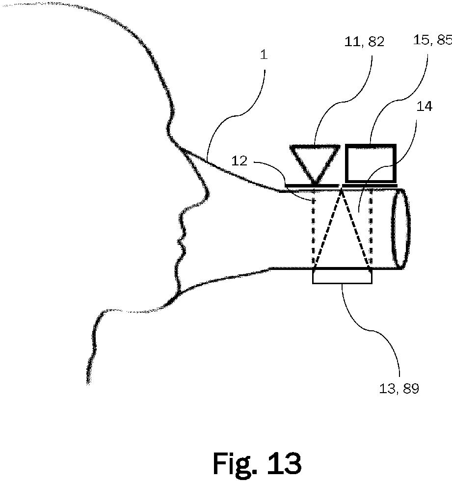
- the Figure 13 shows an advantageous structure of an ergospirometry device according to the invention in a very advantageous embodiment.
- a light source 12 or a beam source 82 is attached directly to a base body 1 (top left in the illustration).
- the sensor spot 13 in the case of the oxygen sensor 10 or a reflector 89 in the case of the carbon dioxide sensor can also be attached directly to the base body on the opposite side.
- the sensor element 15 or the sensor element 85 can then be attached again on the first side of the base body.
- the base body 1 can be transparent and non-fluorescent at least in this section.
- the oxygen sensor 10 (see Fig. 1 ) or the carbon dioxide sensor 80 of the measuring device is connected directly to the base body 1. This enables a very compact design.
- a light source 11 or a beam source 82 can be attached directly to the base body, which makes unwanted contamination more difficult.
- a sensor element 15 or 85 can be attached directly to the base body, which makes unwanted contamination (even more) difficult. So that oxygen can diffuse into the sensor layer, the sensor element can be attached in such a way that the sensor element is in contact with the breathing gas.
- the spot can also be welded to a transparent base body, which also makes unwanted contamination of the spot more difficult.
- the measuring device 4 provided can have properties that are described above.
- the base body 1 provided can have properties that are described above.
- a sensor spot with copper or platinum metal complexes can be coated with a polymer by simply applying the polymer in liquid form and allowing it to dry. In this way, a thin layer can be applied.
- One advantage of this is that the method is inexpensive.
- An advantage of the present ergospirometry device is that it is self-referencing and that it has a very high oxygen sensitivity (down to the ppb range ("parts per billion”)). It can also cover a high dynamic range (optionally up to 9 orders of magnitude).
- the emission quantum yield is also high.
- the metal complex can be a copper-metal complex. This material is inexpensive and easily available. In addition, copper is (probably) non-toxic.
- Another advantage is that the emissions are spectrally separated from one another. This further simplifies the measurement technique and allows an intensity comparison. It should also be noted that an extraordinarily high quantum yield can be achieved with the present ergospirometry device. With the very fast evaluation, the requirements for a breath-by-breath principle are easily met.
Landscapes
- Health & Medical Sciences (AREA)
- Life Sciences & Earth Sciences (AREA)
- Medical Informatics (AREA)
- Molecular Biology (AREA)
- Pulmonology (AREA)
- Biophysics (AREA)
- Pathology (AREA)
- Engineering & Computer Science (AREA)
- Biomedical Technology (AREA)
- Heart & Thoracic Surgery (AREA)
- Physiology (AREA)
- Physics & Mathematics (AREA)
- Surgery (AREA)
- Animal Behavior & Ethology (AREA)
- General Health & Medical Sciences (AREA)
- Public Health (AREA)
- Veterinary Medicine (AREA)
- Emergency Medicine (AREA)
- Obesity (AREA)
- Investigating Or Analysing Materials By The Use Of Chemical Reactions (AREA)
- Investigating, Analyzing Materials By Fluorescence Or Luminescence (AREA)
Abstract
Die vorliegende Erfindung betrifft eine Ergospirometrievorrichtung zur Erfassung von Parametern eines Atemgases, mit einem Grundkörper 1, der eine Atemmaske oder ein Mundstück aufweist und einen Atemgasführungsabschnitt 5 aufweist, und einer Messeinrichtung 4 zum Erfassen von Parametern des Atemgases, die eine Recheneinheit 3 zum Verarbeiten der erfassten Parameter des Atemgases aufweist, wobei die Parameter des Atemgases zumindest eine Sauerstoffkonzentration und/oder eine Kohlenstoffdioxidkonzentration im Atemgas umfassen, wobei die Messeinrichtung 4 zumindest einen optischen Sauerstoffsensor 10 zum Erfassen der Sauerstoffkonzentration des Atemgases und/oder einen optischen Kohlenstoffdioxidsensor aufweist und wobei das Erfassen der Sauerstoffkonzentration auf einem Prinzip der Lumineszenzlöschung und/oder einem Prinzip der dualen Emission beruht.
Description
Die vorliegende Erfindung betrifft eine Ergospirometrievorrichtung zur Erfassung von Parametern eines Atemgases wie beispielsweise die Sauerstoffkonzentration (insbesondere die Disauerstoffkonzentration/O2-Konzentration/Konzentration molekularen Sauerstoffs) und/oder die Kohlendioxidkonzentration (CO2-Konzentration) und ein entsprechendes Herstellungsverfahren.The present invention relates to an ergospirometry device for detecting parameters of a respiratory gas such as the oxygen concentration (in particular the dioxygen concentration/O 2 concentration/molecular oxygen concentration) and/or the carbon dioxide concentration (CO 2 concentration) and a corresponding manufacturing method.
Eine alternative Bezeichnung für Ergospirometrie ist Spiroergometrie. Bei der Ergospirometrie (von έργov ("ergon") Altgriechisch für "Arbeit" oder "Werk", spirare Latein für "atmen" und µέτρov ("metron") Altgriechisch für "Maß") werden Atemgase bei körperlicher Belastung gemessen. Insbesondere kann ein Atemminutenvolumen (oder allgemeiner ein Atemzeitvolumen) gemessen werden. Zudem können die Kohlendioxid- und/oder die (Di-)Sauerstoffkonzentration im Atemgas gemessen werden.An alternative name for ergospirometry is spiroergometry. In ergospirometry (from έργov ("ergon") ancient Greek for "work" or "work", spirare Latin for "breathe" and µέτρov ("metron") ancient Greek for "measure"), respiratory gases are measured during physical exertion. In particular, a minute ventilation volume (or more generally a respiratory time volume) can be measured. In addition, the carbon dioxide and/or (di)oxygen concentration in the respiratory gas can be measured.
Mobile Ergospirometriegeräte, z. B. für Belastungsuntersuchungen beim Menschen, sind seit einigen Jahren bekannt. Mithilfe derartiger Systeme lassen sich Analysen direkt auf dem Sport- oder Arbeitsplatz unter natürlichen Bedingungen und Belastungssituationen durchführen. Über Telemetrieeinheiten werden Messdaten in Echtzeit an einen Personal Computer oder ein Notebook übertragen, wobei eine entsprechende Steuerung des Trainings- oder Übungsverlaufes nach Auswertung der Daten am Personal Computer möglich ist. Durch derartige Geräte wurden neue Anwendungsgebiete in der Leistungsdiagnostik in der Arbeits-, Sport- und Rehabilitationsmedizin erschlossen.Mobile ergospirometry devices, e.g. for stress tests on humans, have been known for several years. Such systems can be used to carry out analyses directly at the sports facility or workplace under natural conditions and stress situations. Telemetry units transmit measurement data in real time to a personal computer or notebook, making it possible to control the training or exercise process after evaluating the data on the personal computer. Such devices have opened up new areas of application in performance diagnostics in occupational, sports and rehabilitation medicine.
Ein Ergospirometriesystem ist beispielsweise aus der
Auch die
Die
Ergospirometrievorrichtungen arbeiten oft in einem sogenannten Mischkammerprinzip, d. h. diese Vorrichtungen sammeln die ausgeatmete Atemluft mehrerer Atemzüge in einer Kammer und führen die Atemgasmessung in dieser Kammer durch. Moderne Ergospirometrievorrichtungen hingegen bestimmen die Atemgasparameter in einem Breath-by-Breath-Prinzip, d. h. diese Ergospirometrievorrichtungen können die Atemgasparameter für jeden Atemstoß bestimmen.Ergospirometry devices often work according to a so-called mixed chamber principle, i.e. these devices collect the exhaled air from several breaths in one chamber and carry out the respiratory gas measurement in this chamber. Modern ergospirometry devices, on the other hand, determine the respiratory gas parameters according to a breath-by-breath principle, i.e. these ergospirometry devices can determine the respiratory gas parameters for each breath.
Eine Aufgabe der vorliegenden Erfindung ist es, eine verbesserte Ergospirometrievorrichtung bereitzustellen, die insbesondere für die Parameter des Atemgases, insbesondere die Konzentration von Sauerstoff und/oder der Konzentration von Kohlendioxid eine deutlich höhere Empfindlichkeit und eine hohe Geschwindigkeit der Auswertung aufweist.An object of the present invention is to provide an improved ergospirometry device which is particularly suitable for the parameters of the breathing gas, in particular the concentration of oxygen and/or the concentration of carbon dioxide, has a significantly higher sensitivity and a high speed of evaluation.
Zur Erfüllung dieses Bedarfs wird vorliegend eine Ergospirometrievorrichtung zur Erfassung von Parametern eines Atemgases vorgeschlagen. Die Ergospirometrievorrichtung kann dabei aufweisen: einen Grundkörper, der eine Atemmaske oder ein Mundstück aufweist und einen Atemgasführungsabschnitt aufweist, und eine Messeinrichtung zum Erfassen von Parametern des Atemgases, die eine Recheneinheit zum Verarbeiten der erfassten Parameter des Atemgases aufweisen kann, wobei die Parameter des Atemgases zumindest eine Sauerstoffkonzentration und/oder eine Kohlenstoffdioxidkonzentration im Atemgas umfassen kann. Die Messeinrichtung kann zumindest einen optischen Sauerstoffsensor zum Erfassen der Sauerstoffkonzentration des Atemgases und/oder einen optischen Kohlenstoffdioxidsensor (bzw. Infrarot-Kohlenstoffdioxidsensor) aufweisen und das Erfassen der Sauerstoffkonzentration kann auf einem Prinzip der Lumineszenzlöschung und/oder einem Prinzip der dualen Emission beruhen.To meet this need, an ergospirometry device for detecting parameters of a respiratory gas is proposed here. The ergospirometry device can have: a base body that has a breathing mask or a mouthpiece and a respiratory gas guide section, and a measuring device for detecting parameters of the respiratory gas, which can have a computing unit for processing the detected parameters of the respiratory gas, wherein the parameters of the respiratory gas can include at least an oxygen concentration and/or a carbon dioxide concentration in the respiratory gas. The measuring device can have at least one optical oxygen sensor for detecting the oxygen concentration of the respiratory gas and/or an optical carbon dioxide sensor (or infrared carbon dioxide sensor), and the detection of the oxygen concentration can be based on a principle of luminescence quenching and/or a principle of dual emission.
Vorzugsweise kann die Messeinrichtung dazu ausgebildet sein, die Erfassung der Sauerstoffkonzentration über eine Lebensdauerauswertung (bspw. der Lumineszenz bzw. physikalischen Lebensdauer einer Lumineszenzabklingkurve) vorzunehmen, durch Zuordnung der gemessenen Lebensdauer zur Sauerstoffkonzentration. Es kann beispielsweise mit einem kurzen Anregungspuls angeregt werden und die Lumineszenzabklingkurve kann beobachtet werden. Beispielsweise kann bei einem einfach exponentiellen Abfall die Lebensdauer aus zwei Intensitäten, die zu den Zeitpunkten t1 und t2 während des Abfalls detektiert werden, bestimmt werden. Bei lumineszierenden Stoffen, deren Lebensdauer in Abhängigkeit der Konzentration eines Quenchers gequencht wird, kann die Lebensdauer mit Hilfe der RLD-Methode bestimmt werden. Das Verfahren Rapid-Lifetime-Determination (RLD) ermöglicht eine schnelle Bestimmung der Lebensdauer von Fluoreszenzsignalen durch Auswertung der Änderung des Fluoreszenzsignals nach einem kurzen Anregungsimpuls, typischerweise 10 bis 100 ns. Die Lebensdauer der Fluoreszenz wird durch eine Exponentialfunktion beschrieben und kann durch eine schnelle Datenaufnahme und -verarbeitung in Echtzeit bestimmt werden. Alternativ (oder auch zusätzlich) kann die Lebensdauer durch Phasenmodulation bestimmt werden. Bei der Phasenmodulation wird die Lebensdauer über den Tangens der Phasenverschiebung dividiert durch die Anregungsfrequenz bestimmt. Alternativ (oder auch zusätzlich) kann die Lebensdauer durch eine Detektion der Zefallsdynamik bestimmt werden.Preferably, the measuring device can be designed to detect the oxygen concentration via a lifetime evaluation (e.g. the luminescence or physical lifetime of a luminescence decay curve) by assigning the measured lifetime to the oxygen concentration. For example, it can be excited with a short excitation pulse and the luminescence decay curve can be observed. For example, in the case of a simple exponential decay, the lifetime can be determined from two intensities that are detected at times t1 and t2 during the decay. In the case of luminescent substances whose lifetime is quenched depending on the concentration of a quencher, the lifetime can be determined using the RLD method. The Rapid Lifetime Determination (RLD) method enables the lifetime of fluorescence signals to be determined quickly by Evaluation of the change in the fluorescence signal after a short excitation pulse, typically 10 to 100 ns. The lifetime of the fluorescence is described by an exponential function and can be determined by fast data acquisition and processing in real time. Alternatively (or additionally), the lifetime can be determined by phase modulation. With phase modulation, the lifetime is determined via the tangent of the phase shift divided by the excitation frequency. Alternatively (or additionally), the lifetime can be determined by detecting the decay dynamics.
Ist für ein System die Lebensdauer in Abhängigkeit der Quencherkonzentration bekannt, so kann der gemessenen Lebensdauer die Quencherkonzentration zugeordnet werden. Dieses Prinzip kann auch zur pixelweisen Berechnung der Lebensdauer genutzt werden, bspw. mittels eines (oder mehrerer) CCD-Flächensensors, und es kann pixelweise eine Konzentration molekularen Sauerstoffs bestimmt werden.If the lifetime of a system is known as a function of the quencher concentration, the quencher concentration can be assigned to the measured lifetime. This principle can also be used to calculate the lifetime pixel by pixel, e.g. using one (or more) CCD area sensors, and a concentration of molecular oxygen can be determined pixel by pixel.
Vorzugsweise kann die Messeinrichtung dazu ausgebildet sein, die Lebensdauerauswertung über eine Detektion der Zerfallsdynamik, über eine schnelle Lebensdauerbestimmung, RLD, "Rapid Lifetime Determination", und/oder über eine Phasenmodulation vorzunehmen.Preferably, the measuring device can be designed to carry out the lifetime evaluation via a detection of the decay dynamics, via a rapid lifetime determination, RLD, and/or via a phase modulation.
Vorzugsweise kann die Messeinrichtung dazu ausgebildet sein, die Erfassung der Sauerstoffkonzentration über eine Auswertung der Quantenausbeute und/oder der Intensität vorzunehmen.Preferably, the measuring device can be designed to detect the oxygen concentration via an evaluation of the quantum yield and/or the intensity.
Vorzugsweise kann die Messeinrichtung zur ratiometrischen Bestimmung der Sauerstoffkonzentration eingerichtet sein und aus einem Intensitätsverhältnis der Fluoreszenz und Phosphoreszenz die Sauerstoffkonzentration bestimmen.Preferably, the measuring device can be designed for the ratiometric determination of the oxygen concentration and can determine the oxygen concentration from an intensity ratio of the fluorescence and phosphorescence.
Vorzugsweise kann der Sauerstoffsensor auf dem Prinzip der Lumineszenzlöschung mit Metall-Komplexen (insbesondere Übergangsmetallkomplexe) arbeiten, wobei die Übergangsmetall-Komplexe bevorzugt Platin und/oder Kupfer umfassen können. Bevorzugt erfolgt die Anregung mit einer schmalbandigen LED, wobei der Photodetektor mit einfacher Optik bei geringem Abstand vorgesehen ist. Bei größerem Abstand können Linsensysteme verwendet werden. Bei Störlicht aus Umgebung kann zudem ein Bandpassfilter verwendet werden.Preferably, the oxygen sensor can be based on the principle of luminescence quenching with metal complexes (in particular Transition metal complexes), whereby the transition metal complexes can preferably comprise platinum and/or copper. Preferably, the excitation is carried out with a narrow-band LED, whereby the photodetector is provided with simple optics at a short distance. At a greater distance, lens systems can be used. In the case of ambient light interference, a bandpass filter can also be used.
Vorzugsweise kann über Variation von Metall-Komplex und Anregungsenergie eine Duale Emission möglich sein, bevorzugt in den Bereichen 375 - 445 nm und 450 - 650 nm, um Informationen über Druck und/oder Temperatur abzuleiten.Preferably, a dual emission can be possible by varying the metal complex and excitation energy, preferably in the ranges 375 - 445 nm and 450 - 650 nm, in order to derive information about pressure and/or temperature.
Vorzugsweise kann der Sensor auch über Feststoffe funktionieren, die nicht fluoreszierend sind und die transparent sind, insbesondere Glas, PC (Polycarbonat), PMMA (Polymethylmethacrylat, auch Acrylglas genannt), PET (Polyethylenterephthalat). Dies ermöglicht ein sehr geringes Messvolumen. Ein kleines Messvolumen hat den Vorteil, dass die Atemluft schnell ausgetauscht werden kann und dass der Atmung mit nur wenig Zeitverzug (Totzeit) und hoher zeitlicher Auflösung der Messwerte gefolgt werden kann. Ein kleines Messvolumen stellt andererseits eine Herausforderung für das Sensordesign dar, da auf dem geringen Volumen die Sensorkomponenten und elektronischen Bauteile untergebracht werden müssen. Mit der vorliegenden Ergospirometrievorrichtung reicht ein Messvolumen von Bruchteilen von einem Milliliter (ml) bis wenige Milliliter für eine korrekte Messung. Vorzugsweise kann das Messvolumen kleiner gleich 0,6 Milliliter betragen, insbesondere zwischen 0,4 und 0,6 Milliliter, insbesondere ungefähr 0,5 Milliliter. Das Messvolumen kann auch kleiner als 0,5 Milliliter sein.Preferably, the sensor can also function via solids that are not fluorescent and that are transparent, in particular glass, PC (polycarbonate), PMMA (polymethyl methacrylate, also called acrylic glass), PET (polyethylene terephthalate). This enables a very small measuring volume. A small measuring volume has the advantage that the breathing air can be exchanged quickly and that breathing can be followed with only a short time delay (dead time) and high temporal resolution of the measured values. On the other hand, a small measuring volume represents a challenge for the sensor design, since the sensor components and electronic components must be accommodated in the small volume. With the present ergospirometry device, a measuring volume of fractions of one milliliter (ml) to a few milliliters is sufficient for a correct measurement. Preferably, the measuring volume can be less than or equal to 0.6 milliliters, in particular between 0.4 and 0.6 milliliters, in particular approximately 0.5 milliliters. The measuring volume can also be less than 0.5 milliliters.
Vorzugsweise kann der Sauerstoffsensor temperatur- und barometrisch kompensiert sein. Beispielsweise kann eine duale Emission mit zwei unterschiedlichen Wellenlängen gemessen werden (2 angeregte Zustände). Die Messeinrichtung kann aber auch zusätzlich einen integrierten Drucksensor umfassen. Zusätzlich oder alternativ dazu kann der Druck auch aus optischen Messungen abgeleitet werden.Preferably, the oxygen sensor can be temperature and barometrically compensated. For example, a dual emission with two different wavelengths can be measured (2 excited states). The measuring device can also have an integrated pressure sensor Additionally or alternatively, the pressure can also be derived from optical measurements.
Vorzugsweise kann eine Sensorschicht des Sauerstoffsensors eine Diffusionskonstante derart aufweisen, dass die Aufnahme eines Messwertes mit einer Zeit von geringer als 5 Sekunden, und besonders bevorzugt geringer als 0,1 s möglich wird. Bevorzugt wird eine Dynamik des Sensors über eine Zeit t10-t90 bestimmt, d. h. über die Zeit, die ein Sensorsignal benötigt, um von 10% auf 90% des Endwertes anzusteigen. Dies hat den Vorteil, dass so Schmutzeffekte von Zuleitungen und Ähnlichem ausgeschlossen werden.Preferably, a sensor layer of the oxygen sensor can have a diffusion constant such that it is possible to record a measured value with a time of less than 5 seconds, and particularly preferably less than 0.1 s. Preferably, a dynamic of the sensor is determined over a time t10-t90, i.e. over the time that a sensor signal requires to increase from 10% to 90% of the final value. This has the advantage that dirt effects from supply lines and the like are excluded.
Vorzugsweise kann ein Trägermaterial der Sensorschicht eine transparente Polyesterschicht oder Polyesterfolie umfassen, welche bevorzugt eine Schichtdicke von weniger als 800 µm aufweist, und wobei die Sensorschicht bevorzugt ein Sensorspot zur kontaktlosen Messung sein kann. Es ist jedoch nicht zwingend ein Trägermaterial erforderlich. Dann kann man ein Metallkomplex direkt (auf die Innenseite des Atemgasführungsabschnitts) auftragen. Vorzugsweise weist die Messeinrichtung einen Sensorspot auf.Preferably, a carrier material of the sensor layer can comprise a transparent polyester layer or polyester film, which preferably has a layer thickness of less than 800 µm, and the sensor layer can preferably be a sensor spot for contactless measurement. However, a carrier material is not absolutely necessary. In this case, a metal complex can be applied directly (to the inside of the breathing gas guide section). Preferably, the measuring device has a sensor spot.
Vorzugsweise kann ein Anregungslicht der Anregungsdiode des Sauerstoffsensors blinken. Vorzugsweise kann ein Anregungslicht der Anregungsdiode des Sauerstoffsensors eine Anregungsfrequenz von mehr als 1 Hz, besonders vorzugsweise zwischen 10 Hz und 100 kHz, aufweisen. Vorzugsweise kann das von der Sensorschicht, insbesondere dem Sensorspot, reflektierte Licht im Bereich von 450 - 650 nm und/oder 375 - 445 nm liegen.Preferably, an excitation light of the excitation diode of the oxygen sensor can flash. Preferably, an excitation light of the excitation diode of the oxygen sensor can have an excitation frequency of more than 1 Hz, particularly preferably between 10 Hz and 100 kHz. Preferably, the light reflected by the sensor layer, in particular the sensor spot, can be in the range of 450 - 650 nm and/or 375 - 445 nm.
Vorzugsweise kann die Messeinrichtung am Grundkörper bereitgestellt sein, damit die Parameter direkt in einem Atemgasstrom erfassbar sind, der durch den Grundkörper geführt wird. Insbesondere ist eine Erfassung der Parameter des Atemgases in situ und/oder in Extraktion möglich.Preferably, the measuring device can be provided on the base body so that the parameters can be recorded directly in a respiratory gas stream that is guided through the base body. In particular, the parameters of the respiratory gas can be recorded in situ and/or in extraction.
Vorzugsweise können zumindest Teile der Messeinrichtung von dem Grundkörper beabstandet sein, sodass eine Erfassung der Parameter des Atemgases in Extraktion ermöglicht wird.Preferably, at least parts of the measuring device can be spaced from the base body so that the parameters of the respiratory gas in extraction can be recorded.
Vorzugsweise kann der Kohlenstoffdioxidsensor zum Erfassen einer Kohlendioxidkonzentration im Atemgas vorgesehen sein, wobei das Erfassen der Kohlendioxidkonzentration im Atemgas auf einem Erfassungsprinzip eines nichtdispersiven Infrarotsensors, NDIR-Prinzip, basieren kann.Preferably, the carbon dioxide sensor can be provided for detecting a carbon dioxide concentration in the respiratory gas, wherein the detection of the carbon dioxide concentration in the respiratory gas can be based on a detection principle of a non-dispersive infrared sensor, NDIR principle.
Vorzugsweise kann der Kohlenstoffdioxidsensor einen Photodetektor und eine Leuchtdiode, insbesondere MIR-LED, für einen Wellenlängenbereich im mittleren Infrarotbereich aufweisen. Insbesondere kann dieser Wellenlängenbereich zwischen 3 µm und 8 µm und besonders vorzugsweise zwischen 4,1 µm und 4,4 µm liegen.Preferably, the carbon dioxide sensor can have a photodetector and a light-emitting diode, in particular MIR-LED, for a wavelength range in the mid-infrared range. In particular, this wavelength range can be between 3 µm and 8 µm and particularly preferably between 4.1 µm and 4.4 µm.
Vorzugsweise kann die Leuchtdiode für einen Wellenlängenbereich im mittleren Infrarot derart modulierbar sein, dass Taktfrequenzen von mindestens 100 kHz erreicht werden.Preferably, the light-emitting diode can be modulated for a wavelength range in the mid-infrared such that clock frequencies of at least 100 kHz are achieved.
Vorzugsweise kann der Photodetektor ein Quantentopf-Infrarot-Photodetektor (Quantum Well Infrared Photodetector, QWIP) sein.Preferably, the photodetector may be a quantum well infrared photodetector (QWIP).
Vorzugsweise kann die Leuchtdiode eine MIR-LED mit einem Reflektor aufweisen, so dass eine sehr hohe Strahlqualität erzielt wird.Preferably, the light-emitting diode can comprise a MIR-LED with a reflector so that a very high beam quality is achieved.
Vorzugsweise kann der Photodetektor zweikanalig ausführt sein, so dass eine Auswertung eines Referenzsignals zur Überwachung des Strahlers ermöglicht wird.Preferably, the photodetector can be designed with two channels, so that an evaluation of a reference signal for monitoring the radiator is possible.
Vorzugsweise kann der Grundkörper den Atemgasführungsabschnitt zur Führung des Atemgasstroms mit einem probandenseitigen Atemgaseinlass und einem Atemgasauslass aufweisen und der Sauerstoffsensor im Atemgasführungsabschnitt vorgesehen sein.Preferably, the base body can provide the breathing gas guide section for guiding the breathing gas flow with a subject-side breathing gas inlet and a have a breathing gas outlet and the oxygen sensor must be provided in the breathing gas guide section.
Vorzugsweise kann die Ergospirometrievorrichtung eine mobile Ergospirometrievorrichtung sein.Preferably, the ergospirometry device can be a mobile ergospirometry device.
Vorzugsweise kann die Ergospirometrievorrichtung zumindest in Teilen, vorzugsweise in Gänze auf Kondensation resistent sein, so dass die Ergospirometrievorrichtung fähig ist, die Parameter des Atemgases auch in Flüssigkeiten zu erfassen.Preferably, the ergospirometry device can be at least partially, preferably entirely, resistant to condensation, so that the ergospirometry device is capable of detecting the parameters of the respiratory gas even in liquids.
Vorzugsweise kann die Messeinrichtung eine Empfindlichkeit bis wenige ppb aufweisen und/oder einen sehr hohen Dynamikumfang bis 100%, bis zu 9 Größenordnungen aufweisen.Preferably, the measuring device can have a sensitivity of up to a few ppb and/or a very high dynamic range of up to 100%, up to 9 orders of magnitude.
Vorzugsweise kann die Sensorvorrichtung selbstreferenzierend sein.Preferably, the sensor device can be self-referencing.
Vorzugsweise kann die Messeinrichtung eine Ansprechzeit von kleiner oder gleich 0,1 s aufweisen.Preferably, the measuring device can have a response time of less than or equal to 0.1 s.
Zur Erfüllung des oben beschriebenen Bedarfs wird vorliegend zudem ein Herstellungsverfahren einer Ergospirometrievorrichtung zur Erfassung von Parametern eines Atemgases beschreiben, wobei das Verfahren folgende Schritte aufweist: Bereitstellen einer Messeinrichtung zum Erfassen von Parametern des Atemgases, die eine Recheneinheit zum Verarbeiten der erfassten Parameter des Atemgases aufweist, Bereitstellen eines Grundkörpers, der eine Atemmaske oder ein Mundstück aufweist, und Verbinden der Messeinrichtung mit dem Grundkörper. Die Messeinrichtung und der Grundkörper können dabei wie oben ausgeführt ausgestaltet sein.To meet the need described above, a manufacturing method of an ergospirometry device for recording parameters of a respiratory gas is also described here, the method comprising the following steps: providing a measuring device for recording parameters of the respiratory gas, which has a computing unit for processing the recorded parameters of the respiratory gas, providing a base body that has a breathing mask or a mouthpiece, and connecting the measuring device to the base body. The measuring device and the base body can be designed as described above.
-
Figur 1 zeigt einen schematischen Aufbau eines Sauerstoffsensors einer erfindungsgemäßen Ergospirometrievorrichtung.Figure 1 shows a schematic structure of an oxygen sensor of an ergospirometry device according to the invention. -
Figur 2 zeigt eine Emissionsintensität eines Kupfer-Metallkomplexes in Abhängigkeit der Wellenlänge bei entsprechender Anregung.Figure 2 shows an emission intensity of a copper-metal complex as a function of the wavelength under appropriate excitation. -
Figur 3 zeigt die Abhängigkeit der Lebensdauer von der Sauerstoffkonzentration bei verschiedenen Temperaturen.Figure 3 shows the dependence of the lifetime on the oxygen concentration at different temperatures. -
Figuren 4a und 4b zeigen schematisch wie verschiedene Sauerstoffkonzentrationen auf das Verhältnis von Fluoreszenz zu Phosphoreszenz Einfluss nimmt.Figures 4a and 4b show schematically how different oxygen concentrations influence the ratio of fluorescence to phosphorescence. -
Figur 5a und 5b zeigen wie verschiedene Temperaturen auf das Lumineszenzverhalten Einfluss nimmt.Figures 5a and 5b show how different temperatures influence the luminescence behavior. -
Figur 6 zeigt den inFigur 5b gezeigten Temperatureinfluss auf einen grünen und einen blauen Kanal.Figure 6 shows theFigure 5b shown temperature influence on a green and a blue channel. -
Figur 7 zeigt die Empfindlichkeit der Sauerstoffsensorik.Figure 7 shows the sensitivity of the oxygen sensor. -
Figur 8 zeigt einen schematischen Aufbau eines Kohlenstoffdioxidsensors.Figure 8 shows a schematic structure of a carbon dioxide sensor. -
Figur 9 zeigt schematisch ein knapp gehaltenes pneumatisches Konzept des Gesamtsystems.Figure 9 shows a brief schematic pneumatic concept of the overall system. -
Figur 10 zeigt eine perspektivische Darstellung einer Messeinrichtung der Ergospirometrievorrichtung.Figure 10 shows a perspective view of a measuring device of the ergospirometry device. -
Figur 11 zeigt die Messeinheit derFigur 9 in einer Schnittdarstellung.Figure 11 shows the unit of measurement ofFigure 9 in a cross-sectional view. -
Figur 12 zeigt einen schematischen Aufbau einer Ergospirometrievorrichtung.Figure 12 shows a schematic structure of an ergospirometry device. -
Figur 13 zeigt einen vorteilhaften Aufbau einer erfindungsgemäßen Ergospirometrievorrichtung.Figure 13 shows an advantageous construction of an ergospirometry device according to the invention.
Die vorliegende Erfindung betrifft eine Ergospirometrievorrichtung, die Parameter eines Atemgases erfasst.The present invention relates to an ergospirometry device that detects parameters of a respiratory gas.
Ein erfinderischer Aspekt dieser Erfindung ist es, eine Sensorik für Sauerstoff, insbesondere Disauerstoff, und Kohlendioxid mit Sensorprinzipien zu entwickeln, die eine Ansprechzeit von <=0,1 s ermöglicht.An inventive aspect of this invention is to develop a sensor for oxygen, in particular dioxygen, and carbon dioxide with sensor principles that enable a response time of <=0.1 s.
Die
Der Sauerstoffsensor arbeitet nach dem Prinzip der Lumineszenzlöschung (auch Quenching genannt, z. B. Fluoreszenzlöschung oder Phosphoreszenzlöschung) mit Metall-Komplexen wie z. B. Platin oder Kupfer. Die sensitive Schicht kann sehr dünn aufgebracht werden, so dass sehr kurze Diffusionskonstanten realisierbar sind. Das Messprinzip funktioniert wie folgt: Es erfolgt eine Anregung mit Wellenlänge X und Antwort des Sensor-Spots mit Wellenlänge Y. Durch die geringe Diffusionskonstante von wenigen ms bis µs ist die Ansprechzeit des Spots sehr schnell. Die Auswertung erfolgt optisch über Licht - ebenfalls sehr schnell.The oxygen sensor works according to the principle of luminescence quenching (also called quenching, e.g. fluorescence quenching or phosphorescence quenching) with metal complexes such as platinum or copper. The sensitive layer can be applied very thinly so that very short diffusion constants can be achieved. The measuring principle works as follows: Excitation occurs with wavelength X and the sensor spot responds with wavelength Y. Due to the low diffusion constant of a few ms to µs, the response time of the spot is very fast. The evaluation is carried out optically using light - also very quickly.
Die
Die
Die
Die
Die
Die
Die Kurve links entspricht der Fluoreszenz / dem blauen Emissionslicht und ist auf Sauerstoff kaum empfindlich. Die Phosphoreszenz / das grüne Emissionslicht hingegen ist sehr sauerstoffempfindlich und wird bei Anwesenheit von Sauerstoff gelöscht. Die Kurve 71 entspricht einer Phosphoreszenz ohne Anwesenheit von Sauerstoff. Die Kurve 72 entspricht der Phosphoreszenz bei Anwesenheit von Luft, die bekanntlich auch (ca. 20,9 Vol.-%) Sauerstoff enthält. Die Kurve 73 entspricht der Phosphoreszenz bei Anwesenheit von reinem Sauerstoff.The curve on the left corresponds to fluorescence/blue emission light and is hardly sensitive to oxygen. Phosphorescence/green emission light, on the other hand, is very sensitive to oxygen and is extinguished in the presence of oxygen.
Vorteile der vorliegenden Ergospirometrievorrichtung umfassen somit unter anderem, dass sie sehr sauerstoffempfindlich ist, dass sie einen sehr hohen dynamischen Bereich abdeckt, und dass deren Messtechnik über einen Intensitätsvergleich sehr einfach ist.Advantages of the present ergospirometry device include, among others, that it is very sensitive to oxygen, that it covers a very high dynamic range, and that its measurement technique is very simple via an intensity comparison.
Die Auswertung kann über Intensität oder Wechselgrößen geschehen.The evaluation can be done via intensity or alternating quantities.
Die Messeinrichtung 4 (siehe
In einer zweiten Ausführungsform der vorliegenden Erfindung wird eine Ergospirometrievorrichtung mit einem Kohlenstoffdioxidsensor vorgestellt. Es sei explizit darauf hingewiesen, dass die zweite Ausführungsform auch mit der ersten Ausführungsform kombiniert werden kann, aber nicht muss.In a second embodiment of the present invention, an ergospirometry device with a carbon dioxide sensor is presented. It should be explicitly noted that the second embodiment can also be combined with the first embodiment, but does not have to be.
Die
Diese Strahlungsquelle 82 beleuchtet das Innere des Hauptkörpers 87, durch den das Gas strömt. Der Strahl 83 der Strahlungsquelle 82 trifft am anderen Ende auf ein Sensorelement 85. Dieses Sensorelement kann vorzugsweise ein Photodetektor, insbesondere ein Quantentopf-Infrarot-Photodetektor (Quantum Well Infrared Photodetector, QWIP) sein. Vorzugsweise kann der Photodetektor zweikanalig ausführt sein, so dass eine Auswertung eines Referenzsignals zur Überwachung des Strahlers ermöglicht wird. Zudem kann über die zwei Kanäle Alterungsprozessen der Strahlungsquelle 82, insbesondere im Falle, dass die Strahlungsquelle 82 eine LED ist, entgegenwirken. Zudem kann über die zwei Kanäle eine Beeinträchtigung durch Verschmutzungen entgegenwirkt werden. Das Erfassen der Kohlendioxidkonzentration im Atemgas kann auf einem Erfassungsprinzip eines nichtdispersiven Infrarotsensors, NDIR-Prinzip, basieren. Damit können schnelle Ansprechzeiten für den Kohlendioxidsensor 80 realisiert werden. Entsprechend kann ein Filter 84 in den Strahlengang zwischen der Strahlenquelle und dem Sensorelement 85 eingebaut sein. Der Filter 84 kann dann die für die Kohlendioxiderfassung relevante Strahlung durchlassen und andere Wellenlängen wegfiltern. Die relevante Strahlung von Kohlendioxid kann eine Wellenlänge bei 4,3 µm sein. Die Strahlung von der Strahlungsquelle 82 kommt bei der relevanten Wellenlänge bis zum Sensorelement 85 durch, wenn sich kein Gas (oder zumindest kein Kohlendioxid) im Innern des Hauptkörpers 87 des Kohlendioxidsensors 80 befindet. Ist jedoch Kohlendioxid vorhanden kommt mit zunehmender Konzentration immer weniger Strahlung durch. Messungen ergaben, dass bei 5000 ppm auf eine Rohrlänge von 200 mm das Signal um 26% abgenommen hatThis
Ein Vorteil dieses Kohlendioxidsensors 80 ist eine sehr kurze Ansprechzeit. Insbesondere kann so eine Ansprechzeit von 0,1 s oder weniger erreicht werden.An advantage of this
Die
Die
Die
Die
Ein weiterer Aspekt der vorliegenden Erfindung ist die Herstellung einer Ergospirometrievorrichtung wie oben beschrieben. Das Verfahren weist folgende Schritte auf:
Bereitstellen einer Messeinrichtung 4 zum Erfassen von Parametern des Atemgases, dieeine Recheneinheit 3 zum Verarbeiten der erfassten Parameter des Atemgases aufweist,Bereitstellen eines Grundkörpers 1, der eine Atemmaske oder ein Mundstück aufweist, undVerbinden der Messeinrichtung 4mit dem Grundkörper 1.
- Providing a
measuring device 4 for detecting parameters of the respiratory gas, which has acomputing unit 3 for processing the detected parameters of the respiratory gas, - Providing a
base body 1 having a breathing mask or a mouthpiece, and - Connecting the
measuring device 4 to thebase body 1.
Die bereitgestellte Messeinrichtung 4 kann dabei Eigenschaften aufweisen, die oben beschrieben sind. Der bereitgestellt Grundkörpers 1 kann dabei Eigenschaften aufweisen, die oben beschrieben sind. Insbesondere kann ein Sensorspot mit Kupfer- oder Platin-Metallkomplexen mit einem Polymer beschichtet werden, indem das Polymer lediglich flüssig aufgetragen und trocknengelassen wird. So kann eine dünne Schicht aufgetragen werden. Ein Vorteil davon ist, dass das Verfahren günstig ist.The measuring
Ein Vorteil der vorliegenden Ergospirometrievorrichtung ist, dass sie selbstreferenzierend ist und dass sie eine sehr hohe Sauerstoff-Empfindlichkeit aufweist (bis in den ppb-Bereich ("parts per billion", also in Teile pro Milliarde)). Es kann zugleich einen hohen dynamischen Bereich (optional bis 9 Größenordnungen) abdecken. Zudem ist auch die Emissionsquantenausbeute hoch. Der Metallkomplex kann ein Kupfer-Metallkomplex sein. Dieses Material ist zum einen preiswert und zum anderen leicht verfügbar. Zudem ist Kupfer (wahrscheinlich) nicht toxisch. Ein weiterer Vorteil ist, dass die Emissionen spektral voneinander getrennt sind. Dies vereinfacht die Messtechnik weiter und erlaubt einen Intensitätsvergleich. Es ist zudem anzumerken, dass mit der vorliegenden Ergospirometrievorrichtung eine außerordentlich hohe Quantenausbeute erzielt werden kann. Mit der sehr schnellen Auswertung werden die Anforderungen für ein Breath-by-Breath-Prinzip mit Leichtigkeit erfüllt.An advantage of the present ergospirometry device is that it is self-referencing and that it has a very high oxygen sensitivity (down to the ppb range ("parts per billion")). It can also cover a high dynamic range (optionally up to 9 orders of magnitude). In addition, the emission quantum yield is also high. The metal complex can be a copper-metal complex. This material is inexpensive and easily available. In addition, copper is (probably) non-toxic. Another advantage is that the emissions are spectrally separated from one another. This further simplifies the measurement technique and allows an intensity comparison. It should also be noted that an extraordinarily high quantum yield can be achieved with the present ergospirometry device. With the very fast evaluation, the requirements for a breath-by-breath principle are easily met.
Claims (15)
wobei optional die Messeinrichtung (4) dazu ausgebildet ist, die Lebensdauerauswertung über eine Detektion der Zerfallsdynamik, über eine schnelle Lebensdauerbestimmung, RLD, "Rapid Lifetime Determination", und/oder über eine Phasenmodulation vorzunehmen.Ergospirometry device according to claim 1, wherein the measuring device (4) is designed to detect the oxygen concentration via a lifetime evaluation,
wherein optionally the measuring device (4) is designed to carry out the lifetime evaluation via a detection of the decay dynamics, via a rapid lifetime determination, RLD, and/or via a phase modulation.
wobei die Messeinrichtung (4) zur ratiometrischen Bestimmung der Sauerstoffkonzentration eingerichtet ist, aus einem Intensitätsverhältnis der Fluoreszenz und Phosphoreszenz die Sauerstoffkonzentration zu bestimmen.Ergospirometry device according to claim 1 or 2, wherein the measuring device (4) is designed to detect the oxygen concentration via an evaluation of the quantum yield and/or the intensity, and/or
wherein the measuring device (4) for the ratiometric determination of the oxygen concentration is designed to determine the oxygen concentration from an intensity ratio of the fluorescence and phosphorescence.
wobei über Variation von Metall-Komplex und Anregungsenergie eine Duale Emission möglich ist, bevorzugt in den Bereichen 375 - 445 nm und 450 - 650 nm, um Informationen über Druck und/oder Temperatur abzuleiten.Ergospirometry device according to at least one of the preceding claims, wherein the oxygen sensor (10) operates on the principle of luminescence quenching with metal complexes - optionally transition metal complexes - and/or polymers and wherein the transition metal complexes preferably comprise platinum and/or copper, and/or
By varying the metal complex and excitation energy, dual emission is possible, preferably in the ranges 375 - 445 nm and 450 - 650 nm, in order to derive information about pressure and/or temperature.
wobei die Messeinrichtung (4) eine Empfindlichkeit bis wenige ppb aufweist und/oder einen sehr hohen Dynamikumfang bis 100%, bis zu 9 Größenordnungen aufweist.Ergospirometry device according to at least one of the preceding claims, wherein the ergospirometry device is at least partially, preferably entirely, resistant to condensation, so that the ergospirometry device is capable of detecting at least some of the parameters of the respiratory gas - in particular an oxygen concentration of the respiratory gas - even at high humidity or with condensing water in the measuring chamber, and/or
wherein the measuring device (4) has a sensitivity of up to a few ppb and/or a very high dynamic range of up to 100%, up to 9 orders of magnitude.
Applications Claiming Priority (1)
| Application Number | Priority Date | Filing Date | Title |
|---|---|---|---|
| DE102023204890.6A DE102023204890A1 (en) | 2023-05-25 | 2023-05-25 | Ergospirometry device and corresponding manufacturing process |
Publications (1)
| Publication Number | Publication Date |
|---|---|
| EP4467072A1 true EP4467072A1 (en) | 2024-11-27 |
Family
ID=91276894
Family Applications (1)
| Application Number | Title | Priority Date | Filing Date |
|---|---|---|---|
| EP24178157.4A Pending EP4467072A1 (en) | 2023-05-25 | 2024-05-27 | Ergospirometry device and corresponding manufacturing method |
Country Status (2)
| Country | Link |
|---|---|
| EP (1) | EP4467072A1 (en) |
| DE (1) | DE102023204890A1 (en) |
Citations (10)
| Publication number | Priority date | Publication date | Assignee | Title |
|---|---|---|---|---|
| WO2001008554A1 (en) * | 1999-08-02 | 2001-02-08 | Healthetech, Inc. | Metabolic calorimeter employing respiratory gas analysis |
| DE19960257C1 (en) | 1999-11-16 | 2001-08-16 | Cortex Biophysik Gmbh | Ergospirometry system for animals, especially horses, camels or the like |
| US20020138213A1 (en) * | 2001-03-02 | 2002-09-26 | Mault James R. | System and method of metabolic rate measurement |
| DE19953866B4 (en) | 1999-10-27 | 2004-05-13 | Cortex Biophysik Gmbh | Mobile ergospirometry system |
| US20090227887A1 (en) * | 2008-03-04 | 2009-09-10 | Howard C Peter | Metabolic analyzer transducer |
| US20110009764A1 (en) * | 2009-04-14 | 2011-01-13 | Deka Product Limited Partnership | Devices, systems, and methods for aiding in the detection of a physiological abnormality |
| CN106814051A (en) * | 2016-12-21 | 2017-06-09 | 哈尔滨工业大学 | The system and method for oxygen content in a kind of room temperature phosphorimetry detection patient's expiration based on metalloporphyrin |
| DE102016214702A1 (en) | 2016-08-08 | 2018-02-08 | Markus Knestel | Spiroergometrievorrichtung |
| CN212853459U (en) * | 2020-03-12 | 2021-04-02 | 中国医学科学院阜外医院 | A turbo-type gas flow and CO2, O2 concentration fast sampling probe |
| US11524187B1 (en) * | 2012-04-06 | 2022-12-13 | Orbital Research Inc. | Biometric and environmental monitoring and control system |
Family Cites Families (1)
| Publication number | Priority date | Publication date | Assignee | Title |
|---|---|---|---|---|
| US10786693B1 (en) * | 2012-04-06 | 2020-09-29 | Orbital Research Inc. | Biometric and environmental monitoring and control system |
-
2023
- 2023-05-25 DE DE102023204890.6A patent/DE102023204890A1/en active Pending
-
2024
- 2024-05-27 EP EP24178157.4A patent/EP4467072A1/en active Pending
Patent Citations (10)
| Publication number | Priority date | Publication date | Assignee | Title |
|---|---|---|---|---|
| WO2001008554A1 (en) * | 1999-08-02 | 2001-02-08 | Healthetech, Inc. | Metabolic calorimeter employing respiratory gas analysis |
| DE19953866B4 (en) | 1999-10-27 | 2004-05-13 | Cortex Biophysik Gmbh | Mobile ergospirometry system |
| DE19960257C1 (en) | 1999-11-16 | 2001-08-16 | Cortex Biophysik Gmbh | Ergospirometry system for animals, especially horses, camels or the like |
| US20020138213A1 (en) * | 2001-03-02 | 2002-09-26 | Mault James R. | System and method of metabolic rate measurement |
| US20090227887A1 (en) * | 2008-03-04 | 2009-09-10 | Howard C Peter | Metabolic analyzer transducer |
| US20110009764A1 (en) * | 2009-04-14 | 2011-01-13 | Deka Product Limited Partnership | Devices, systems, and methods for aiding in the detection of a physiological abnormality |
| US11524187B1 (en) * | 2012-04-06 | 2022-12-13 | Orbital Research Inc. | Biometric and environmental monitoring and control system |
| DE102016214702A1 (en) | 2016-08-08 | 2018-02-08 | Markus Knestel | Spiroergometrievorrichtung |
| CN106814051A (en) * | 2016-12-21 | 2017-06-09 | 哈尔滨工业大学 | The system and method for oxygen content in a kind of room temperature phosphorimetry detection patient's expiration based on metalloporphyrin |
| CN212853459U (en) * | 2020-03-12 | 2021-04-02 | 中国医学科学院阜外医院 | A turbo-type gas flow and CO2, O2 concentration fast sampling probe |
Non-Patent Citations (1)
| Title |
|---|
| XU-DONG WANG ET AL: "Optical methods for sensing and imaging oxygen: materials, spectroscopies and applications", CHEMICAL SOCIETY REVIEWS, vol. 43, no. 10, 1 January 2014 (2014-01-01), UK, pages 3666 - 3761, XP055365171, ISSN: 0306-0012, DOI: 10.1039/C4CS00039K * |
Also Published As
| Publication number | Publication date |
|---|---|
| DE102023204890A1 (en) | 2024-11-28 |
Similar Documents
| Publication | Publication Date | Title |
|---|---|---|
| EP2032967B1 (en) | Spectroscopic detector and method for determining the presence of blood and biological marker substances in liquids | |
| DE69523216T2 (en) | Multidetector measuring head for a photometer | |
| DE10008517C2 (en) | Optical measuring system | |
| DE10163775A1 (en) | Analysis system for determining an analyte concentration taking into account sample and analyte-independent changes in light intensity | |
| DE19948587A1 (en) | Spectrophotometric and nephelometric detection unit | |
| DE19844500A1 (en) | Process for the photometric evaluation of test elements | |
| WO2007090378A2 (en) | Measuring device for determining the size size distribution and amount of particles in the nanoscopic range | |
| WO2007115732A1 (en) | Analysis of optical data with the aid of histograms | |
| DE10248555B4 (en) | Method and analysis system for determining the concentration of an analyte in a sample, which consists of the analyte and the sample matrix, and test element therefor | |
| EP2288902B1 (en) | Apparatus for determining the element coverage on a glass surface using fluorescence | |
| AT406912B (en) | Optical measurement arrangement for determining transmitted and scattered radiation | |
| EP1921441B1 (en) | Method for analysing a sample on a test element and analysis system | |
| EP4467072A1 (en) | Ergospirometry device and corresponding manufacturing method | |
| EP2380003B1 (en) | Measuring arrangement for determining at least one parameter of a blood sample | |
| EP1843147A1 (en) | Spatially resolved analysis of optical data of a test element | |
| DE102017001175B4 (en) | spectrometer | |
| EP4415618A2 (en) | Device and method for determining flow | |
| WO2022174277A1 (en) | Optical unit for measuring fluorescent light | |
| DE10118449C1 (en) | Device for monitoring a chemical stream used in the synthesis of DNA comprises a base body having a tubular recess, light measuring paths represented by light sources and a light | |
| DE10221115B4 (en) | Apparatus and method for the determination of chemical or biochemical partners of general receptor-ligand systems contained in samples | |
| DE102006011565B4 (en) | Gas sensor system | |
| DE4411661A1 (en) | Multi-parameter video technical analysis process for fluid media | |
| EP1682892A1 (en) | Method and device for detecting analytes | |
| DE202008007542U1 (en) | Device for determining the element occupancy on a surface by means of fluorescence | |
| EP3504537B1 (en) | Device for measuring fluorescence using a printed circuit board with mounted light source and detector, wherein the printed circuit board contains a slit for suppressing conduction of light |
Legal Events
| Date | Code | Title | Description |
|---|---|---|---|
| PUAI | Public reference made under article 153(3) epc to a published international application that has entered the european phase |
Free format text: ORIGINAL CODE: 0009012 |
|
| STAA | Information on the status of an ep patent application or granted ep patent |
Free format text: STATUS: THE APPLICATION HAS BEEN PUBLISHED |
|
| AK | Designated contracting states |
Kind code of ref document: A1 Designated state(s): AL AT BE BG CH CY CZ DE DK EE ES FI FR GB GR HR HU IE IS IT LI LT LU LV MC ME MK MT NL NO PL PT RO RS SE SI SK SM TR |
|
| STAA | Information on the status of an ep patent application or granted ep patent |
Free format text: STATUS: REQUEST FOR EXAMINATION WAS MADE |
|
| 17P | Request for examination filed |
Effective date: 20250527 |