EP4410493A1 - Power tool including interface for connecting accessory attachments - Google Patents
Power tool including interface for connecting accessory attachments Download PDFInfo
- Publication number
- EP4410493A1 EP4410493A1 EP24155093.8A EP24155093A EP4410493A1 EP 4410493 A1 EP4410493 A1 EP 4410493A1 EP 24155093 A EP24155093 A EP 24155093A EP 4410493 A1 EP4410493 A1 EP 4410493A1
- Authority
- EP
- European Patent Office
- Prior art keywords
- power tool
- accessory attachment
- interface
- housing
- battery pack
- Prior art date
- Legal status (The legal status is an assumption and is not a legal conclusion. Google has not performed a legal analysis and makes no representation as to the accuracy of the status listed.)
- Pending
Links
- 238000004891 communication Methods 0.000 claims description 15
- 230000004044 response Effects 0.000 claims description 8
- 238000000034 method Methods 0.000 description 10
- 238000003780 insertion Methods 0.000 description 3
- 230000037431 insertion Effects 0.000 description 3
- 238000005259 measurement Methods 0.000 description 3
- WHXSMMKQMYFTQS-UHFFFAOYSA-N Lithium Chemical compound [Li] WHXSMMKQMYFTQS-UHFFFAOYSA-N 0.000 description 2
- PXHVJJICTQNCMI-UHFFFAOYSA-N Nickel Chemical compound [Ni] PXHVJJICTQNCMI-UHFFFAOYSA-N 0.000 description 2
- 230000001419 dependent effect Effects 0.000 description 2
- 230000000881 depressing effect Effects 0.000 description 2
- 229910052744 lithium Inorganic materials 0.000 description 2
- 229910001416 lithium ion Inorganic materials 0.000 description 2
- HBBGRARXTFLTSG-UHFFFAOYSA-N Lithium ion Chemical compound [Li+] HBBGRARXTFLTSG-UHFFFAOYSA-N 0.000 description 1
- KLARSDUHONHPRF-UHFFFAOYSA-N [Li].[Mn] Chemical compound [Li].[Mn] KLARSDUHONHPRF-UHFFFAOYSA-N 0.000 description 1
- 239000002253 acid Substances 0.000 description 1
- 230000004913 activation Effects 0.000 description 1
- 230000000712 assembly Effects 0.000 description 1
- 238000000429 assembly Methods 0.000 description 1
- CKFRRHLHAJZIIN-UHFFFAOYSA-N cobalt lithium Chemical compound [Li].[Co] CKFRRHLHAJZIIN-UHFFFAOYSA-N 0.000 description 1
- 238000010276 construction Methods 0.000 description 1
- 230000007423 decrease Effects 0.000 description 1
- 230000000994 depressogenic effect Effects 0.000 description 1
- 239000003302 ferromagnetic material Substances 0.000 description 1
- 230000005291 magnetic effect Effects 0.000 description 1
- 229910052987 metal hydride Inorganic materials 0.000 description 1
- 238000012986 modification Methods 0.000 description 1
- 230000004048 modification Effects 0.000 description 1
- 229910052759 nickel Inorganic materials 0.000 description 1
- 229910052596 spinel Inorganic materials 0.000 description 1
- 239000011029 spinel Substances 0.000 description 1
Images


Classifications
-
- B—PERFORMING OPERATIONS; TRANSPORTING
- B25—HAND TOOLS; PORTABLE POWER-DRIVEN TOOLS; MANIPULATORS
- B25F—COMBINATION OR MULTI-PURPOSE TOOLS NOT OTHERWISE PROVIDED FOR; DETAILS OR COMPONENTS OF PORTABLE POWER-DRIVEN TOOLS NOT PARTICULARLY RELATED TO THE OPERATIONS PERFORMED AND NOT OTHERWISE PROVIDED FOR
- B25F5/00—Details or components of portable power-driven tools not particularly related to the operations performed and not otherwise provided for
- B25F5/02—Construction of casings, bodies or handles
-
- B—PERFORMING OPERATIONS; TRANSPORTING
- B25—HAND TOOLS; PORTABLE POWER-DRIVEN TOOLS; MANIPULATORS
- B25F—COMBINATION OR MULTI-PURPOSE TOOLS NOT OTHERWISE PROVIDED FOR; DETAILS OR COMPONENTS OF PORTABLE POWER-DRIVEN TOOLS NOT PARTICULARLY RELATED TO THE OPERATIONS PERFORMED AND NOT OTHERWISE PROVIDED FOR
- B25F5/00—Details or components of portable power-driven tools not particularly related to the operations performed and not otherwise provided for
-
- F—MECHANICAL ENGINEERING; LIGHTING; HEATING; WEAPONS; BLASTING
- F21—LIGHTING
- F21V—FUNCTIONAL FEATURES OR DETAILS OF LIGHTING DEVICES OR SYSTEMS THEREOF; STRUCTURAL COMBINATIONS OF LIGHTING DEVICES WITH OTHER ARTICLES, NOT OTHERWISE PROVIDED FOR
- F21V21/00—Supporting, suspending, or attaching arrangements for lighting devices; Hand grips
-
- F—MECHANICAL ENGINEERING; LIGHTING; HEATING; WEAPONS; BLASTING
- F21—LIGHTING
- F21V—FUNCTIONAL FEATURES OR DETAILS OF LIGHTING DEVICES OR SYSTEMS THEREOF; STRUCTURAL COMBINATIONS OF LIGHTING DEVICES WITH OTHER ARTICLES, NOT OTHERWISE PROVIDED FOR
- F21V33/00—Structural combinations of lighting devices with other articles, not otherwise provided for
- F21V33/008—Leisure, hobby or sport articles, e.g. toys, games or first-aid kits; Hand tools; Toolboxes
- F21V33/0084—Hand tools; Toolboxes
-
- H—ELECTRICITY
- H01—ELECTRIC ELEMENTS
- H01M—PROCESSES OR MEANS, e.g. BATTERIES, FOR THE DIRECT CONVERSION OF CHEMICAL ENERGY INTO ELECTRICAL ENERGY
- H01M50/00—Constructional details or processes of manufacture of the non-active parts of electrochemical cells other than fuel cells, e.g. hybrid cells
- H01M50/20—Mountings; Secondary casings or frames; Racks, modules or packs; Suspension devices; Shock absorbers; Transport or carrying devices; Holders
- H01M50/247—Mountings; Secondary casings or frames; Racks, modules or packs; Suspension devices; Shock absorbers; Transport or carrying devices; Holders specially adapted for portable devices, e.g. mobile phones, computers, hand tools or pacemakers
-
- H—ELECTRICITY
- H01—ELECTRIC ELEMENTS
- H01M—PROCESSES OR MEANS, e.g. BATTERIES, FOR THE DIRECT CONVERSION OF CHEMICAL ENERGY INTO ELECTRICAL ENERGY
- H01M50/00—Constructional details or processes of manufacture of the non-active parts of electrochemical cells other than fuel cells, e.g. hybrid cells
- H01M50/20—Mountings; Secondary casings or frames; Racks, modules or packs; Suspension devices; Shock absorbers; Transport or carrying devices; Holders
- H01M50/296—Mountings; Secondary casings or frames; Racks, modules or packs; Suspension devices; Shock absorbers; Transport or carrying devices; Holders characterised by terminals of battery packs
-
- H—ELECTRICITY
- H01—ELECTRIC ELEMENTS
- H01M—PROCESSES OR MEANS, e.g. BATTERIES, FOR THE DIRECT CONVERSION OF CHEMICAL ENERGY INTO ELECTRICAL ENERGY
- H01M2220/00—Batteries for particular applications
- H01M2220/30—Batteries in portable systems, e.g. mobile phone, laptop
Definitions
- the present disclosure relates to power tools, and more particularly to power tool assemblies including accessory attachments.
- the present disclosure provides, in one aspect, a power tool assembly including a power tool.
- the power tool includes a housing, an electric motor supported within the housing, a battery pack coupled to the housing and configured to supply electrical current to the electric motor, an electronic control unit configured to selectively activate the electric motor with electrical current from the battery pack, and an interface on the housing.
- the interface includes a first plurality of electrical terminals that provide electrical current from the battery pack.
- the power tool assembly also includes an accessory attachment removably coupled to the interface.
- the accessory attachment includes a second plurality of electrical terminals that are electrically connectable with the first plurality of electrical terminals when the accessory attachment is coupled to the interface.
- the disclosure described herein relates to a power tool assembly, wherein the accessory attachment is configured to be slid onto the interface.
- the disclosure described herein relates to a power tool assembly, wherein the interface is positioned proximal to the battery pack.
- the disclosure described herein relates to a power tool assembly, wherein the interface includes a slot, wherein the slot includes a first end and a second end.
- the disclosure described herein relates to a power tool assembly, wherein the accessory attachment includes a rail, wherein the slot is configured to receive the rail.
- the disclosure described herein relates to a power tool assembly, wherein the slot defines a slot length measured from the first end to the second end, wherein the rail defines a rail length measured from a first rail end to a second rail end, and wherein the slot length and the rail length are equal.
- the disclosure described herein relates to a power tool assembly, wherein the second plurality of electrical terminals are disposed on the rail.
- the disclosure described herein relates to a power tool assembly, wherein the second plurality of electrical terminals are spring loaded.
- the disclosure described herein relates to a power tool assembly, wherein the accessory attachment includes a switch configured to detect a user input and to output a signal, wherein the electronic control unit is in communication with the switch, wherein the electronic control unit is configured to receive the signal from the switch, and wherein the electronic control unit is configured to limit the electrical current supplied to the electric motor in response to the signal from the switch.
- the disclosure described herein relates to a power tool assembly, wherein the accessory attachment includes a light source configured to illuminate an area and wherein the battery pack is configured to supply electrical current to the light source.
- the disclosure described herein relates to a power tool assembly, wherein the accessory attachment includes a distance sensor.
- the disclosure described herein relates to a power tool assembly, wherein the accessory attachment includes electrical components, the electrical components are electronically connected to the second plurality of electrical terminals and to the electronic control unit.
- the disclosure described herein relates to a power tool assembly, wherein the electrical components of the accessory attachment are configured as a stud finder.
- the present disclosure provides, in another aspect, a power tool assembly including a power tool.
- the power tool includes a housing, an electric motor supported within the housing, a battery pack coupled to the housing and configured to supply electrical current to the electric motor, an electronic control unit configured to selectively activate the electric motor with electrical current from the battery pack, and an interface on the housing.
- the interface includes one of a slot or a rail.
- the power tool assembly also includes an accessory attachment configured to be removably coupled to the interface.
- the accessory attachment includes the other of the slot or the rail.
- the rail is received within the slot to secure the accessory attachment to the interface, thereby supporting the accessory attachment on the power tool.
- the disclosure described herein relates to a power tool assembly, wherein the interface includes a first plurality of electrical terminals that provide electrical current from the battery pack and wherein the accessory attachment includes a second plurality of electrical terminals that are electrically connectable with the first plurality of electrical terminals when the accessory attachment is coupled to the interface.
- the disclosure described herein relates to a power tool assembly, wherein the accessory attachment includes non-electric components.
- the disclosure described herein relates to a power tool assembly, wherein the non-electric components include a magnet.
- a power tool including a housing, an electric motor supported within the housing, a battery pack coupled to the housing and configured to supply electrical current to the electric motor, an electronic control unit configured to selectively activate the electric motor with electrical current from the battery pack, and an interface on the housing.
- the interface includes a first plurality of electrical terminals that provide electrical current from the battery pack.
- the interface of the power tool assembly is configured to be removable coupled to an accessory attachment.
- the accessory attachment includes a second plurality of electrical terminals that are electrically connectable with the first plurality of electrical terminals when the accessory attachment is coupled to the interface.
- the present disclosure further provides a method of controlling a power tool assembly.
- the method includes receiving, with a housing of a power tool, a battery pack configured to supply electrical current to an electric motor of the power tool, the electric motor supported within the housing, and the housing including an interface that includes a first plurality of electrical terminals.
- the method includes receiving an accessory attachment with the interface on the housing.
- the method includes connecting the first plurality of electrical terminals with a second plurality of electrical terminals disposed on the accessory attachment.
- the method includes controlling, with an electronic control unit of the power tool, a supply of the electrical current from the battery pack to the electric motor.
- the method includes supplying, with the first plurality of electrical terminals, electrical current from the battery pack to the interface.
- FIG. 1 illustrates a power tool assembly 100A including a power tool 104A (e.g., a drill driver).
- the power tool 104A includes a housing 108A supporting an electric motor 112 and a battery pack 116 coupled to the housing 108A.
- the battery pack 116 is configured to supply electrical current to the electric motor 112 of the power tool 104A.
- the power tool 104A includes an electronic control unit 120 that is configured to selectively activate the electric motor 112 with electrical current from the battery pack 116.
- the power tool 104A includes an actuator (e.g., a trigger 124) configured to receive a user input.
- the trigger 124 is configured to detect the user input and output an electrical signal to the electronic control unit 120.
- the battery pack 116 may be an 18-volt rechargeable power tool battery pack 116.
- the battery pack 116 may include multiple battery cells having, for example, a lithium (Li), lithium-ion (Li-ion), or other lithium-based chemistry.
- the battery cells may have a chemistry of lithium-cobalt (Li-Co), lithium-manganese (Li-Mn) spinel, or Li-Mn nickel.
- each battery cell may have a nominal voltage of about, for example, 3.6V, 4.0V, or 4.2V.
- the battery cells may have a nickelcadmium, nickel-metal hydride, or lead acid battery chemistry.
- the power tool 104A includes an interface 136A located on an outer side wall 140A of the base 132A and extends in a front-rear direction of the base 132A (and thus the power tool 104A).
- the interface 136A is also located above the battery pack 116 when it is attached to the power tool 104A. In other words, the interface 136A is positioned proximal to the battery pack 116.
- the interface 136A may be located on a front wall or a rear wall of the base 132A (see FIG. 11 ). In other embodiments, the interface 136A can be located anywhere on the housing 108A.
- the slot 144A includes an open first end 166 and a closed second end 168 opposite the first end 166. An opening for the slot 144A is at the first end 166.
- the slot 144A defines a slot length S that is measured from the first end 166 to the second end 168 ( FIGS. 2 and 3 ).
- the outer side wall 140A includes a tapered portion 172 that decreases a depth of the slot 144A over an initial segment of the slot length S.
- the interface 136A includes a first plurality of electrical terminals 176 that provide electrical current from the battery pack 116.
- the first plurality of electrical terminals 176 include a power terminal 178 and a ground terminal 180 that provide electrical current from the battery pack 116.
- the first plurality of electrical terminals 176 also include a pair of communication terminals 182 that enable electronic connection to the electronic control unit 120.
- the interface 136A includes the communication terminals 182 that are connected to the electronic control unit 120 for communication.
- FIG. 4 illustrates the power tool assembly 100A including an accessory attachment 186A, according to an embodiment of the disclosure.
- the accessory attachment 186A is selectively coupled to the power tool 104A at the interface 136A.
- the accessory attachment 186A includes a rail with a corresponding geometry to fit in the slot 144A, such that the rail is slidably received within the slot 144A.
- the accessory attachment 186A optionally includes a second plurality of electrical terminals 190 that electrically connect with first plurality of electrical terminals 176.
- the accessory attachment 186A is optionally supplied electrical current from the battery pack 116 though the first and the second plurality of electrical terminals 176, 190.
- the accessory attachment 186A optionally includes electrical components 194 that are electronically connected to the second plurality of electrical terminals 190.
- the electrical components 194 are optionally electronically connected to the electronic control unit 120.
- the accessory attachment 186A optionally includes non-electric components 198. Specific examples of the optional electrical components 194 and non-electric components 198 are discussed in detail below.
- FIG. 5 illustrates an accessory attachment 200, according to another embodiment of the present disclosure.
- the accessory attachment 200 is alternately connectable to the interface 136A on the power tool 104A.
- the accessory attachment 200 includes a housing 204 and a rail 208 extending therefrom.
- the rail 208 has a complimentary shape to the slot 144A.
- the rail 208 includes a first lip 212 that is configured to engage the hook 160 and second lip 216 that is configured to engage the second hook 164 to facilitate sliding movement therebetween.
- the rail 208 includes a first rail end 220 and a second rail end 224.
- the rail 208 defines a rail length R measured from the first rail end 220 to the second rail end 224.
- a second plurality of electrical terminals 228 are disposed on the rail 208 and include a power terminal 230, a ground terminal 232, and a pair of communication terminals 234.
- the second plurality of electrical terminals 228 are spring loaded.
- the accessory attachment 200 includes a printed circuit board (PCB 238) that is coupled to the housing 204 with fasteners 240.
- the PCB 238 is electronically coupled to the second plurality of electrical terminals 228.
- the PCB 238 includes a switch (i.e., a dial 242) that is configured to detect a user input and output an electrical signal.
- FIG. 6 illustrates the accessory attachment 200 mounted to the interface 136A.
- the rail 208 is slidably engaged with the slot 144A, such that the accessory attachment 200 is supported by the base 132A. In other words, the rail 208 is received within the slot 144A to secure the accessory attachment 200 to the interface 136A.
- the second rail end 224 is inserted into the opening proximal to the first end 166 of the slot 144A.
- the second plurality of electrical terminals 228 may recede into the rail 208 when contacting the outer side wall 140A.
- the first and the second rail ends 220, 224 are proximal to the first and the second ends 166, 168 of the slot 144A, respectively.
- the slot lengths S and the rail length R are equal.
- the second plurality of electrical terminals 228 are electrically connected with the first plurality of electrical terminals 176, permitting the battery pack 116 to supply the accessory attachment 200 with electrical current through the power terminals 178, 230.
- the electronic control unit 120 is electronically connected to the accessory attachment 200 by the pair of communication terminals 234 such that the electronic control unit 120 may receive an electrical signal corresponding with movement of the dial 242.
- the dial 242 is configured detect a desired maximum speed of the electric motor 112. As background, the speed of the electric motor 112 is dependent on the amount of electrical current supplied to the electric motor 112 by the electronic control unit 120. As described earlier, the electronic control unit 120 supplies electrical current to the electric motor 112 in response to the user depressing the trigger 124. Normally, the user can reach maximum speed of the electric motor 112 by fully depressing the trigger 124 and the electronic control unit 120 can supply maximum electrical current (i.e., 0-100% PWM) to the electric motor 112. However, the dial 242 can "remap" the amount of electrical current supplied to the electric motor 112 by the electronic control unit 120 when the trigger 124 is depressed.
- the user can rotate the dial 242 a first direction to reduce the maximum speed of the electric motor 112.
- the electronic control unit 120 detects this input from the dial 242 and limits the supply of maximum current to the electric motor 112 to a value less than 100% PWM (e.g., may limit maximum current 0-20% PWM) when the user fully depresses the trigger 124.
- the dial 242 provide an input to the electronic control unit 120 to limit the amount of electrical current supplied to the electric motor 112.
- the electronic control unit 120 includes memory to store the remapping of the maximum speed. Thereafter, the accessory attachment 200 can be removed from the power tool 104A and the new maximum speed will remain programmed in the electronic control unit 120. The user may readjust the desired maximum speed of the electric motor 112 by reattaching the accessory attachment 200 and readjusting the dial 242 as described above.
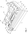
- FIG. 7 illustrates another accessory attachment 300 that is alternately connectable to the interface 136A on the power tool 104A.
- the accessory attachment 300 includes a housing 304 with a rail 308 having a first lip 312 and a second lip 316 that is configured to facilitate sliding movement therebetween.
- the accessory attachment 300 includes the second plurality of electrical terminals 320 including a power terminal 322, a ground terminal 324, and a pair of communication terminals 326.
- the accessory attachment 300 includes a printed circuit board (PCB 330) that is coupled to the housing with fasteners.
- the PCB 330 is electronically coupled to the second plurality of electrical terminals 320.
- the PCB 330 includes a switch (i.e., a dial 334) that is configured to detect a user input and output a signal.
- the housing includes a pair of arms 338 including a hinge 342.
- the accessory attachment 300 includes a light source 346 (e.g., a light emitting diode or "LED") that is coupled to the hinge 342. In the illustrated embodiment, there are six LEDs 346.
- the LEDs 346 are pivotable about the hinge 342 by the user and is placed toward a front of the tool. LEDs 346 are electrically connected to the PCB 330 to receive electrical current therefrom and emit light when activated.
- FIG. 8 illustrates the accessory attachment 300 mounted to the interface 136A.
- the rail 308 is slidably engaged with the slot 144A, such that the accessory attachment 300 is supported by the base 132A.
- the second plurality of electrical terminals 320 are electrically connected with the first plurality of electrical terminals 176 such that the battery pack 116 supplies the accessory attachment 300 with electrical current through the power terminals 178, 322.
- the LEDs 346 receive electrical current supplied from the battery pack 116.
- the dial 334 is configured to activate the LEDs 346. Specifically, the user adjusts the dial 334 to activate the LEDs 346 with electrical current from the battery pack 116. When activated, the LEDs 346 illuminates a work area.
- the dial 334 is configured to adjust a brightness of the LEDs 346.
- the brightness of the LEDs 346 is dependent on the amount of electrical current supplied to the LEDs 346.
- the PCB 330 may increase the electrical current supplied to the LEDs 346 from the battery pack 116 depending on adjustment of the dial 334.
- adjustment of the dial 334 also changes the brightness of the onboard work light in addition to the brightness of the LEDs 346 on the accessory attachment 300.
- FIG. 9 illustrates another accessory attachment 400 that is alternately connectable to the interface 136A on the power tool 104A.
- the accessory attachment 400 includes a housing 404 with a rail 408 having a first lip 412 and a second lip 416 that is configured to facilitate sliding movement therebetween.
- the accessory attachment 400 includes the second plurality of electrical terminals 420 including a power terminal 422, a ground terminal 424, and a pair of communication terminals 426.
- the accessory attachment 400 includes a printed circuit board (PCB 430) that is coupled to the housing with fasteners.
- the PCB 430 is electronically coupled to the second plurality of electrical terminals 420.
- the PCB 430 includes a switch (i.e., a dial 434) that is configured to detect a user input and output an electrical signal.
- the housing includes a pair of arms 438 and a hinge 442.
- the accessory attachment 400 includes a screen 446 pivotally coupled to the hinge 442 to adjust the viewing angle by the user.
- the screen 446 is electrically connected to the PCB 430.
- the accessory attachment 400 also includes a time-of-flight laser sensor 450 that is electrically connected to the PCB 430.
- FIG. 10 illustrates the accessory attachment 400 mounted to the interface 136A.
- the rail 408 is slidably engaged with the slot 144A, such that the accessory attachment 400 is supported by the base 132A.
- the second plurality of electrical terminals 420 are electrically connected with the first plurality of electrical terminals 176 such that the battery pack 116 supplies the accessory attachment 400 with electrical current through the power terminals 178, 422.
- the time-of-flight laser sensor 450 and the screen 446 receive electrical current from the battery pack 116.
- the time-of-flight laser sensor 450 is configured to detect a work surface and output an electrical signal to the PCB 430, which then calculates a distance between the power tool 104A and the work surface.
- the calculated distance is displayed on the screen 446 in a first section 454 of the screen 446.
- the accessory attachment 400 is a distance sensor.
- the dial 434 is adjusted to set a minimum or maximum distance from the workpiece in which the power tool 104A is operable (i.e., a target distance). Specifically, the user may adjust the dial 434 to vary the target distance, which is displayed in a second section 458 of the screen 446.
- the dial 434 outputs or sends an electrical signal to the PCB 430 to set the target distance.
- the electronic control unit 120 can deactivate the electric motor 112, thereby preventing activation of the electric motor 112 and stopping the work operation with the power tool 104A.
- the target distance may be used in an instance where the user wants to drill a fastener to a specific depth with the power tool 104A.
- the screen 446 displays a unit of measurement in a third section 462 of the screen 446.
- the user may adjust the unit of measurement using the dial 434.
- FIGS. 11 and 12 illustrate another embodiment of a power tool assembly 100B including a power tool 104B having a housing 108B.
- the housing 108B supports the electric motor 112 and the battery pack 116 coupled to the housing 108B.
- the power tool 104B includes the electronic control unit 120.
- the housing 108B includes the handle portion 128 and a base 132B to which the battery pack 116 is attached.
- the housing 108B includes an interface 136B located on an outer side wall 140B of the base 132B that extends in a left-right direction of the base 132B (and thus the power tool 104B).
- FIG. 11 illustrates an accessory attachment 186B coupled to the interface 136B.
- the interface 136B includes an accessory slot 144B collectively defined by the outer side wall 140B, a first wall 148B, a second wall 152B, a third wall 156B.
- the first wall 148B extends from the outer side wall 140B and the third wall 156B.
- the second wall 152B extends from the outer side wall 140B and the third wall 156B.
- the first wall 148B and the second wall 152B are perpendicular from the outer side wall 140B and the third wall 156B.
- the first wall 148B and the second wall 152B are parallel to one another.
- the third wall 156B extends from the outer side wall 140B and between the first wall 148B and the second wall 152B.
- the interface 136B is integrated with the base 132B of the housing 108B.
- the slot 144B includes an open first end 166 and a closed second end 168 opposite the first end 166. An opening for the slot 144B is at the first end 166.
- the third wall 156B includes an aperture 500.
- the interface 136B includes the first plurality of electrical terminals 176 that provide electrical current from the battery pack 116.
- the first plurality of electrical terminals 176 include a power terminal 178 and a ground terminal 180 that provide electrical current from the battery pack 116.
- the first plurality of electrical terminals 176 also include a pair of communication terminals 182 that enable electronic connection to the electronic control unit 120.
- the interface 136B includes the communication terminals 182 that are connected to the electronic control unit 120 for communication.
- the first plurality of electrical terminals 176 are disposed on the outer side wall 140B.
- the accessory attachment 186B is selectively coupled to the power tool 104B at the interface 136B.
- the accessory attachment 186B includes a rail with a corresponding geometry to fit in the slot 144B, such that the rail is slidably received within the slot 144B.
- the rail of the accessory attachment 186B is configured to be received by the first and the second walls 148B, 152B.
- the accessory attachment 186B includes a latch 504 with a corresponding geometry to the aperture 500 of the third wall 156B.
- the latch 504 is spring-loaded so that the protrusion 504 is recessed into the accessory attachment 186B when the accessory attachment 186B is slid into the slot 144B. When the accessory attachment 186B is completely received in the slot 144B, the latch 504 is configured to extend into the aperture 500, thereby locking the accessory attachment 186B to the power tool 104B.
- the accessory attachment 186B optionally includes a second plurality of electrical terminals 190 that electrically connect with the first plurality of electrical terminals 176. The accessory attachment 186B is optionally supplied electrical current from the battery pack 116 though the first and the second plurality of electrical terminals 176, 190.
- the accessory attachment 186 optionally includes electrical components 194 that are electronically connected to the second plurality of electrical terminals 190.
- the electrical components 194 include a light source (e.g., a light emitting diode or "LED").
- the electrical components 194 are optionally electronically connected to the electronic control unit 120.
- the accessory attachment 186B optionally includes non-electric components 198. Specific examples of the optional electrical components 194 and non-electric components 198 are discussed in detail below.
- the electrical components 194 are compatible with the accessory attachments 186A, 186B (e.g., accessory attachment 186) of each of the respective power tools 104A, 104B (e.g., power tool 104).
- the electrical components 194 of the accessory attachment 186 are configured to provide a tool lockout mode.
- the electrical components 194 are powered by the battery pack 116.
- the user may activate the tool lockout with the electrical components 194.
- the electrical components 194 detect a user input and output a signal to the electronic control unit 120.
- the electronic control unit 120 receives the signal and does not supply the electric motor 112 with electrical current from the battery pack 116 (i.e., a lockout mode).
- the power tool 104 In the lockout mode, the power tool 104 is incapable of operation. In an unlocked state, the power tool 104 is capable of operation.
- the electronic control unit 120 includes memory to store the lockout mode. As such, the accessory attachment 186 can be removed from the power tool 104 and the lockout mode will remain programmed in the electronic control unit 120. The user may reattach the accessory attachment 186 and deactivate the lockout mode with the electrical components.
- the electrical components 194 of the accessory attachment 186 are configured to provide media control.
- the electrical components 194 are powered by the battery pack 116.
- the electrical components 194 are configured to connect to speakers and/or a media player, and provide the ability to play, pause, rewind, skip, and control the volume of the connected media.
- the electrical components 194 of the accessory attachment 186 are configured to be in communication with other power tools.
- the electrical components 194 are powered by the battery pack 116.
- the electrical components 194 may communicate with a vacuum.
- the electrical components 194 are configured to provide a signal to turn the vacuum on or off.
- the signals sent to the vacuum by the electrical components 194 are controlled by the electronic control unit 120. For instance, the electronic control unit 120 may instruct the electrical components 194 to turn the vacuum on or off depending on if the electric motor 112 is active.
- the electrical components 194 of the accessory attachment 186 are configured as a stud finder.
- the electrical components 194 of the accessory attachment 186 are configured to configured to communicate data of the tool and the tool's surroundings to an external source.
- the electrical components 194 are powered by the battery pack 116.
- Examples of an external source could include a display or a computer.
- An example of tool data is a measurement of the battery life of the tool.
- An example of data for the tool's surroundings is the distance of the tool from a workpiece.
- the electrical components 194 of the accessory attachment 186 are configured as a location tracker using GPS, Bluetooth, and/or near-field communication (NFC).
- NFC near-field communication
- the non-electric components 198 of the accessory attachment 186 are configured as a bubble level. In some embodiments, the non-electric components 198 of the accessory attachment 186 are configured as a magnet configured to receive ferromagnetic material. Specifically, the magnet is in the form of a magnetic parts tray. In some embodiments, the non-electric components 198 of the accessory attachment 186 are configured as a belt clip receiver. In some embodiments, the non-electric components 198 of the accessory attachment 186 are configured as carpenter's pencil storage. In some embodiments, the non-electric components 198 of the accessory attachment 186 are configured as a bit-bar attachment to hold bit bars.
Landscapes
- Engineering & Computer Science (AREA)
- Mechanical Engineering (AREA)
- General Engineering & Computer Science (AREA)
- Chemical & Material Sciences (AREA)
- Chemical Kinetics & Catalysis (AREA)
- Electrochemistry (AREA)
- General Chemical & Material Sciences (AREA)
- Life Sciences & Earth Sciences (AREA)
- Biophysics (AREA)
- Computer Hardware Design (AREA)
- Battery Mounting, Suspending (AREA)
Abstract
A power tool assembly includes a power tool. The power tool includes a housing, an electric motor supported within the housing, a battery pack coupled to the housing and configured to supply electrical current to the electric motor, an electronic control unit configured to selectively activate the electric motor with electrical current from the battery pack, and an interface on the housing. The interface includes a first plurality of electrical terminals that provide electrical current from the battery pack. The power tool assembly also includes an accessory attachment removably coupled to the interface. The accessory attachment includes a second plurality of electrical terminals that are electrically connectable with the first plurality of electrical terminals when the accessory attachment is coupled to the interface.
Description
- This application claims priority to
U.S. Provisional Patent Application No. 63/483,063, filed February 3, 2023 - The present disclosure relates to power tools, and more particularly to power tool assemblies including accessory attachments.
- The present disclosure provides, in one aspect, a power tool assembly including a power tool. The power tool includes a housing, an electric motor supported within the housing, a battery pack coupled to the housing and configured to supply electrical current to the electric motor, an electronic control unit configured to selectively activate the electric motor with electrical current from the battery pack, and an interface on the housing. The interface includes a first plurality of electrical terminals that provide electrical current from the battery pack. The power tool assembly also includes an accessory attachment removably coupled to the interface. The accessory attachment includes a second plurality of electrical terminals that are electrically connectable with the first plurality of electrical terminals when the accessory attachment is coupled to the interface.
- In some aspects, the disclosure described herein relates to a power tool assembly, wherein the accessory attachment is configured to be slid onto the interface.
- In some aspects, the disclosure described herein relates to a power tool assembly, wherein the interface is positioned proximal to the battery pack.
- In some aspects, the disclosure described herein relates to a power tool assembly, wherein the interface includes a slot, wherein the slot includes a first end and a second end.
- In some aspects, the disclosure described herein relates to a power tool assembly, wherein the accessory attachment includes a rail, wherein the slot is configured to receive the rail.
- In some aspects, the disclosure described herein relates to a power tool assembly, wherein the slot defines a slot length measured from the first end to the second end, wherein the rail defines a rail length measured from a first rail end to a second rail end, and wherein the slot length and the rail length are equal.
- In some aspects, the disclosure described herein relates to a power tool assembly, wherein the second plurality of electrical terminals are disposed on the rail.
- In some aspects, the disclosure described herein relates to a power tool assembly, wherein the second plurality of electrical terminals are spring loaded.
- In some aspects, the disclosure described herein relates to a power tool assembly, wherein the accessory attachment includes a switch configured to detect a user input and to output a signal, wherein the electronic control unit is in communication with the switch, wherein the electronic control unit is configured to receive the signal from the switch, and wherein the electronic control unit is configured to limit the electrical current supplied to the electric motor in response to the signal from the switch.
- In some aspects, the disclosure described herein relates to a power tool assembly, wherein the accessory attachment includes a light source configured to illuminate an area and wherein the battery pack is configured to supply electrical current to the light source.
- In some aspects, the disclosure described herein relates to a power tool assembly, wherein the accessory attachment includes a distance sensor.
- In some aspects, the disclosure described herein relates to a power tool assembly, wherein the accessory attachment includes electrical components, the electrical components are electronically connected to the second plurality of electrical terminals and to the electronic control unit.
- In some aspects, the disclosure described herein relates to a power tool assembly, wherein the electrical components of the accessory attachment are configured as a stud finder.
- The present disclosure provides, in another aspect, a power tool assembly including a power tool. The power tool includes a housing, an electric motor supported within the housing, a battery pack coupled to the housing and configured to supply electrical current to the electric motor, an electronic control unit configured to selectively activate the electric motor with electrical current from the battery pack, and an interface on the housing. The interface includes one of a slot or a rail. The power tool assembly also includes an accessory attachment configured to be removably coupled to the interface. The accessory attachment includes the other of the slot or the rail. The rail is received within the slot to secure the accessory attachment to the interface, thereby supporting the accessory attachment on the power tool.
- In some aspects, the disclosure described herein relates to a power tool assembly, wherein the interface includes a first plurality of electrical terminals that provide electrical current from the battery pack and wherein the accessory attachment includes a second plurality of electrical terminals that are electrically connectable with the first plurality of electrical terminals when the accessory attachment is coupled to the interface.
- In some aspects, the disclosure described herein relates to a power tool assembly, wherein the accessory attachment includes non-electric components.
- In some aspects, the disclosure described herein relates to a power tool assembly, wherein the non-electric components include a magnet.
- The present disclosure provides, in one aspect, a power tool including a housing, an electric motor supported within the housing, a battery pack coupled to the housing and configured to supply electrical current to the electric motor, an electronic control unit configured to selectively activate the electric motor with electrical current from the battery pack, and an interface on the housing. The interface includes a first plurality of electrical terminals that provide electrical current from the battery pack. The interface of the power tool assembly is configured to be removable coupled to an accessory attachment. The accessory attachment includes a second plurality of electrical terminals that are electrically connectable with the first plurality of electrical terminals when the accessory attachment is coupled to the interface.
- The present disclosure further provides a method of controlling a power tool assembly. The method includes receiving, with a housing of a power tool, a battery pack configured to supply electrical current to an electric motor of the power tool, the electric motor supported within the housing, and the housing including an interface that includes a first plurality of electrical terminals. The method includes receiving an accessory attachment with the interface on the housing. The method includes connecting the first plurality of electrical terminals with a second plurality of electrical terminals disposed on the accessory attachment. The method includes controlling, with an electronic control unit of the power tool, a supply of the electrical current from the battery pack to the electric motor. The method includes supplying, with the first plurality of electrical terminals, electrical current from the battery pack to the interface.
- Other features and aspects of the disclosure will become apparent by consideration of the following detailed description and accompanying drawings.
-
-
FIG. 1 is a perspective view of a power tool including an interface for connecting accessory attachments. -
FIG. 2 is an enlarged perspective view of the power tool and the interface ofFIG. 1 . -
FIG. 3 is a side view of the power tool and the interface ofFIG. 1 . -
FIG. 4 is a perspective view of a power tool assembly including the power tool ofFIG. 1 with an accessory attachment coupled to the interface. -
FIG. 5 is a perspective view of an accessory attachment for use with the power tool ofFIG. 1 . -
FIG. 6 is a perspective view of the accessory attachment ofFIG. 5 coupled to the interface of the power tool ofFIG. 1 . -
FIG. 7 is a perspective view of an accessory attachment for use with the power tool ofFIG. 1 . -
FIG. 8 is a perspective view of the accessory attachment ofFIG. 7 coupled to the interface of the power tool ofFIG. 1 . -
FIG. 9 is a perspective view of an accessory attachment for use with the power tool ofFIG. 1 . -
FIG. 10 is a perspective view of the accessory attachment ofFIG. 9 coupled to the interface of the power tool ofFIG. 1 . -
FIG. 11 is a perspective view of another power tool assembly including an accessory attachment coupled to a power tool. -
FIG. 12 is an exploded view of the power tool assembly ofFIG. 11 . - Before any embodiments of the disclosure are explained in detail, it is to be understood that the disclosure is not limited in its application to the details of construction and the arrangement of components set forth in the following description or illustrated in the following drawings. The disclosure is capable of other embodiments and of being practiced or of being carried out in various ways.
-
FIG. 1 illustrates apower tool assembly 100A including apower tool 104A (e.g., a drill driver). Thepower tool 104A includes ahousing 108A supporting anelectric motor 112 and abattery pack 116 coupled to thehousing 108A. Thebattery pack 116 is configured to supply electrical current to theelectric motor 112 of thepower tool 104A. Thepower tool 104A includes anelectronic control unit 120 that is configured to selectively activate theelectric motor 112 with electrical current from thebattery pack 116. Thepower tool 104A includes an actuator (e.g., a trigger 124) configured to receive a user input. Thetrigger 124 is configured to detect the user input and output an electrical signal to theelectronic control unit 120. Theelectronic control unit 120 is configured to receive the signal from thetrigger 124 and to selectively activate theelectric motor 112 with electrical current from thebattery pack 116. Thehousing 108A includes ahandle portion 128 and abase 132A to which thebattery pack 116 is attached. - In some embodiments, the
battery pack 116 may be an 18-volt rechargeable powertool battery pack 116. Thebattery pack 116 may include multiple battery cells having, for example, a lithium (Li), lithium-ion (Li-ion), or other lithium-based chemistry. For example, the battery cells may have a chemistry of lithium-cobalt (Li-Co), lithium-manganese (Li-Mn) spinel, or Li-Mn nickel. In such embodiments, each battery cell may have a nominal voltage of about, for example, 3.6V, 4.0V, or 4.2V. In other embodiments, the battery cells may have a nickelcadmium, nickel-metal hydride, or lead acid battery chemistry. In further embodiments, thebattery pack 116 may include fewer or more battery cells, and/or the battery cells may have a different nominal voltage. In yet another embodiment, thebattery pack 116 may be a dedicated battery housed (partially or entirely) within thepower tool 104A. Thebattery pack 116 may also be configured for use with other cordless power tools, such as drills, screwdrivers, grinders, wrenches, and saws. - With reference to
FIGS. 1-3 , thepower tool 104A includes aninterface 136A located on anouter side wall 140A of thebase 132A and extends in a front-rear direction of thebase 132A (and thus thepower tool 104A). Theinterface 136A is also located above thebattery pack 116 when it is attached to thepower tool 104A. In other words, theinterface 136A is positioned proximal to thebattery pack 116. In other embodiments, theinterface 136A may be located on a front wall or a rear wall of thebase 132A (seeFIG. 11 ). In other embodiments, theinterface 136A can be located anywhere on thehousing 108A. The interface includes anaccessory slot 144A collectively defined by theouter side wall 140A, afirst wall 148A, asecond wall 152A, athird wall 156A. Thefirst wall 148A extends from theouter side wall 140A and includes ahook 160 that is perpendicular to thefirst wall 148A and extends toward thesecond wall 152A. Thesecond wall 152A extends from theouter side wall 140A and includes ahook 164 that is perpendicular to thesecond wall 152A and extends toward thefirst wall 148A. Thethird wall 156A extends from theouter side wall 140A and between the first and thesecond wall interface 136A is integrated with thebase 132A of thehousing 108A. Theslot 144A includes an openfirst end 166 and a closedsecond end 168 opposite thefirst end 166. An opening for theslot 144A is at thefirst end 166. Theslot 144A defines a slot length S that is measured from thefirst end 166 to the second end 168 (FIGS. 2 and3 ). Theouter side wall 140A includes a taperedportion 172 that decreases a depth of theslot 144A over an initial segment of the slot length S. - With continued reference to
FIGS. 2 and3 , theinterface 136A includes a first plurality ofelectrical terminals 176 that provide electrical current from thebattery pack 116. Specifically, the first plurality ofelectrical terminals 176 include apower terminal 178 and aground terminal 180 that provide electrical current from thebattery pack 116. The first plurality ofelectrical terminals 176 also include a pair ofcommunication terminals 182 that enable electronic connection to theelectronic control unit 120. In one or more embodiments, theinterface 136A includes thecommunication terminals 182 that are connected to theelectronic control unit 120 for communication. -
FIG. 4 illustrates thepower tool assembly 100A including anaccessory attachment 186A, according to an embodiment of the disclosure. Theaccessory attachment 186A is selectively coupled to thepower tool 104A at theinterface 136A. In some embodiments, theaccessory attachment 186A includes a rail with a corresponding geometry to fit in theslot 144A, such that the rail is slidably received within theslot 144A. Theaccessory attachment 186A optionally includes a second plurality ofelectrical terminals 190 that electrically connect with first plurality ofelectrical terminals 176. Theaccessory attachment 186A is optionally supplied electrical current from thebattery pack 116 though the first and the second plurality ofelectrical terminals accessory attachment 186A optionally includeselectrical components 194 that are electronically connected to the second plurality ofelectrical terminals 190. Theelectrical components 194 are optionally electronically connected to theelectronic control unit 120. Theaccessory attachment 186A optionally includesnon-electric components 198. Specific examples of the optionalelectrical components 194 andnon-electric components 198 are discussed in detail below. -
FIG. 5 illustrates anaccessory attachment 200, according to another embodiment of the present disclosure. Theaccessory attachment 200 is alternately connectable to theinterface 136A on thepower tool 104A. Theaccessory attachment 200 includes ahousing 204 and arail 208 extending therefrom. Therail 208 has a complimentary shape to theslot 144A. Specifically, therail 208 includes afirst lip 212 that is configured to engage thehook 160 andsecond lip 216 that is configured to engage thesecond hook 164 to facilitate sliding movement therebetween. Therail 208 includes afirst rail end 220 and asecond rail end 224. Therail 208 defines a rail length R measured from thefirst rail end 220 to thesecond rail end 224. A second plurality ofelectrical terminals 228 are disposed on therail 208 and include apower terminal 230, aground terminal 232, and a pair ofcommunication terminals 234. The second plurality ofelectrical terminals 228 are spring loaded. Theaccessory attachment 200 includes a printed circuit board (PCB 238) that is coupled to thehousing 204 withfasteners 240. ThePCB 238 is electronically coupled to the second plurality ofelectrical terminals 228. ThePCB 238 includes a switch (i.e., a dial 242) that is configured to detect a user input and output an electrical signal. -
FIG. 6 illustrates theaccessory attachment 200 mounted to theinterface 136A. Therail 208 is slidably engaged with theslot 144A, such that theaccessory attachment 200 is supported by thebase 132A. In other words, therail 208 is received within theslot 144A to secure theaccessory attachment 200 to theinterface 136A. During insertion of theaccessory attachment 200, thesecond rail end 224 is inserted into the opening proximal to thefirst end 166 of theslot 144A. During insertion, the second plurality ofelectrical terminals 228 may recede into therail 208 when contacting theouter side wall 140A. Upon complete insertion, the first and the second rail ends 220, 224 are proximal to the first and the second ends 166, 168 of theslot 144A, respectively. The slot lengths S and the rail length R are equal. When theaccessory attachment 200 is coupled to theinterface 136A, the second plurality ofelectrical terminals 228 are electrically connected with the first plurality ofelectrical terminals 176, permitting thebattery pack 116 to supply theaccessory attachment 200 with electrical current through thepower terminals accessory attachment 200 is coupled to theinterface 136A, theelectronic control unit 120 is electronically connected to theaccessory attachment 200 by the pair ofcommunication terminals 234 such that theelectronic control unit 120 may receive an electrical signal corresponding with movement of thedial 242. - In the illustrated embodiment, the
dial 242 is configured detect a desired maximum speed of theelectric motor 112. As background, the speed of theelectric motor 112 is dependent on the amount of electrical current supplied to theelectric motor 112 by theelectronic control unit 120. As described earlier, theelectronic control unit 120 supplies electrical current to theelectric motor 112 in response to the user depressing thetrigger 124. Normally, the user can reach maximum speed of theelectric motor 112 by fully depressing thetrigger 124 and theelectronic control unit 120 can supply maximum electrical current (i.e., 0-100% PWM) to theelectric motor 112. However, thedial 242 can "remap" the amount of electrical current supplied to theelectric motor 112 by theelectronic control unit 120 when thetrigger 124 is depressed. For example, the user can rotate the dial 242 a first direction to reduce the maximum speed of theelectric motor 112. Theelectronic control unit 120 detects this input from thedial 242 and limits the supply of maximum current to theelectric motor 112 to a value less than 100% PWM (e.g., may limit maximum current 0-20% PWM) when the user fully depresses thetrigger 124. In other words, thedial 242 provide an input to theelectronic control unit 120 to limit the amount of electrical current supplied to theelectric motor 112. Theelectronic control unit 120 includes memory to store the remapping of the maximum speed. Thereafter, theaccessory attachment 200 can be removed from thepower tool 104A and the new maximum speed will remain programmed in theelectronic control unit 120. The user may readjust the desired maximum speed of theelectric motor 112 by reattaching theaccessory attachment 200 and readjusting thedial 242 as described above. -
FIG. 7 illustrates anotheraccessory attachment 300 that is alternately connectable to theinterface 136A on thepower tool 104A. Similar to theaccessory attachment 200, theaccessory attachment 300 includes ahousing 304 with arail 308 having afirst lip 312 and asecond lip 316 that is configured to facilitate sliding movement therebetween. Theaccessory attachment 300 includes the second plurality ofelectrical terminals 320 including apower terminal 322, aground terminal 324, and a pair ofcommunication terminals 326. Theaccessory attachment 300 includes a printed circuit board (PCB 330) that is coupled to the housing with fasteners. ThePCB 330 is electronically coupled to the second plurality ofelectrical terminals 320. ThePCB 330 includes a switch (i.e., a dial 334) that is configured to detect a user input and output a signal. The housing includes a pair ofarms 338 including ahinge 342. Theaccessory attachment 300 includes a light source 346 (e.g., a light emitting diode or "LED") that is coupled to thehinge 342. In the illustrated embodiment, there are sixLEDs 346. TheLEDs 346 are pivotable about thehinge 342 by the user and is placed toward a front of the tool.LEDs 346 are electrically connected to thePCB 330 to receive electrical current therefrom and emit light when activated. -
FIG. 8 illustrates theaccessory attachment 300 mounted to theinterface 136A. Therail 308 is slidably engaged with theslot 144A, such that theaccessory attachment 300 is supported by thebase 132A. When theaccessory attachment 300 is coupled to theinterface 136A, the second plurality ofelectrical terminals 320 are electrically connected with the first plurality ofelectrical terminals 176 such that thebattery pack 116 supplies theaccessory attachment 300 with electrical current through thepower terminals LEDs 346 receive electrical current supplied from thebattery pack 116. In the illustrated embodiment, thedial 334 is configured to activate theLEDs 346. Specifically, the user adjusts thedial 334 to activate theLEDs 346 with electrical current from thebattery pack 116. When activated, theLEDs 346 illuminates a work area. In the illustrated embodiment, thedial 334 is configured to adjust a brightness of theLEDs 346. The brightness of theLEDs 346 is dependent on the amount of electrical current supplied to theLEDs 346. ThePCB 330 may increase the electrical current supplied to theLEDs 346 from thebattery pack 116 depending on adjustment of thedial 334. In some embodiments of thepower tool 104A having an onboard work light, adjustment of thedial 334 also changes the brightness of the onboard work light in addition to the brightness of theLEDs 346 on theaccessory attachment 300. -
FIG. 9 illustrates anotheraccessory attachment 400 that is alternately connectable to theinterface 136A on thepower tool 104A. Similar to theaccessory attachments accessory attachment 400 includes ahousing 404 with arail 408 having afirst lip 412 and asecond lip 416 that is configured to facilitate sliding movement therebetween. Theaccessory attachment 400 includes the second plurality ofelectrical terminals 420 including apower terminal 422, aground terminal 424, and a pair ofcommunication terminals 426. Theaccessory attachment 400 includes a printed circuit board (PCB 430) that is coupled to the housing with fasteners. ThePCB 430 is electronically coupled to the second plurality ofelectrical terminals 420. ThePCB 430 includes a switch (i.e., a dial 434) that is configured to detect a user input and output an electrical signal. The housing includes a pair ofarms 438 and ahinge 442. Theaccessory attachment 400 includes ascreen 446 pivotally coupled to thehinge 442 to adjust the viewing angle by the user. Thescreen 446 is electrically connected to thePCB 430. Theaccessory attachment 400 also includes a time-of-flight laser sensor 450 that is electrically connected to thePCB 430. -
FIG. 10 illustrates theaccessory attachment 400 mounted to theinterface 136A. Therail 408 is slidably engaged with theslot 144A, such that theaccessory attachment 400 is supported by thebase 132A. When theaccessory attachment 400 is coupled to theinterface 136A, the second plurality ofelectrical terminals 420 are electrically connected with the first plurality ofelectrical terminals 176 such that thebattery pack 116 supplies theaccessory attachment 400 with electrical current through thepower terminals flight laser sensor 450 and thescreen 446 receive electrical current from thebattery pack 116. The time-of-flight laser sensor 450 is configured to detect a work surface and output an electrical signal to thePCB 430, which then calculates a distance between thepower tool 104A and the work surface. The calculated distance is displayed on thescreen 446 in afirst section 454 of thescreen 446. Theaccessory attachment 400 is a distance sensor. Thedial 434 is adjusted to set a minimum or maximum distance from the workpiece in which thepower tool 104A is operable (i.e., a target distance). Specifically, the user may adjust thedial 434 to vary the target distance, which is displayed in asecond section 458 of thescreen 446. Thedial 434 outputs or sends an electrical signal to thePCB 430 to set the target distance. Upon reaching the target distance, theelectronic control unit 120 can deactivate theelectric motor 112, thereby preventing activation of theelectric motor 112 and stopping the work operation with thepower tool 104A. In some embodiments, the target distance may be used in an instance where the user wants to drill a fastener to a specific depth with thepower tool 104A. Thescreen 446 displays a unit of measurement in a third section 462 of thescreen 446. In some embodiments, the user may adjust the unit of measurement using thedial 434. -
FIGS. 11 and12 illustrate another embodiment of apower tool assembly 100B including apower tool 104B having ahousing 108B. Thehousing 108B supports theelectric motor 112 and thebattery pack 116 coupled to thehousing 108B. Thepower tool 104B includes theelectronic control unit 120. Thehousing 108B includes thehandle portion 128 and a base 132B to which thebattery pack 116 is attached. In contrast to thehousing 108A of thepower tool 104A, thehousing 108B includes aninterface 136B located on anouter side wall 140B of thebase 132B that extends in a left-right direction of thebase 132B (and thus thepower tool 104B).FIG. 11 illustrates anaccessory attachment 186B coupled to theinterface 136B. - With reference to
FIG. 12 , theinterface 136B includes anaccessory slot 144B collectively defined by theouter side wall 140B, afirst wall 148B, asecond wall 152B, athird wall 156B. Thefirst wall 148B extends from theouter side wall 140B and thethird wall 156B. Thesecond wall 152B extends from theouter side wall 140B and thethird wall 156B. Thefirst wall 148B and thesecond wall 152B are perpendicular from theouter side wall 140B and thethird wall 156B. Thefirst wall 148B and thesecond wall 152B are parallel to one another. Thethird wall 156B extends from theouter side wall 140B and between thefirst wall 148B and thesecond wall 152B. In the illustrated embodiment, theinterface 136B is integrated with the base 132B of thehousing 108B. Theslot 144B includes an openfirst end 166 and a closedsecond end 168 opposite thefirst end 166. An opening for theslot 144B is at thefirst end 166. Thethird wall 156B includes anaperture 500. With continued reference toFIG. 12 , theinterface 136B includes the first plurality ofelectrical terminals 176 that provide electrical current from thebattery pack 116. Specifically, the first plurality ofelectrical terminals 176 include apower terminal 178 and aground terminal 180 that provide electrical current from thebattery pack 116. The first plurality ofelectrical terminals 176 also include a pair ofcommunication terminals 182 that enable electronic connection to theelectronic control unit 120. In one or more embodiments, theinterface 136B includes thecommunication terminals 182 that are connected to theelectronic control unit 120 for communication. The first plurality ofelectrical terminals 176 are disposed on theouter side wall 140B. - With continued reference to
FIG. 12 , theaccessory attachment 186B is selectively coupled to thepower tool 104B at theinterface 136B. In the illustrated embodiment, theaccessory attachment 186B includes a rail with a corresponding geometry to fit in theslot 144B, such that the rail is slidably received within theslot 144B. Specifically, the rail of theaccessory attachment 186B is configured to be received by the first and thesecond walls accessory attachment 186B includes a latch 504 with a corresponding geometry to theaperture 500 of thethird wall 156B. In some embodiments, the latch 504 is spring-loaded so that the protrusion 504 is recessed into theaccessory attachment 186B when theaccessory attachment 186B is slid into theslot 144B. When theaccessory attachment 186B is completely received in theslot 144B, the latch 504 is configured to extend into theaperture 500, thereby locking theaccessory attachment 186B to thepower tool 104B. In the illustrated embodiment, theaccessory attachment 186B optionally includes a second plurality ofelectrical terminals 190 that electrically connect with the first plurality ofelectrical terminals 176. Theaccessory attachment 186B is optionally supplied electrical current from thebattery pack 116 though the first and the second plurality ofelectrical terminals electrical components 194 that are electronically connected to the second plurality ofelectrical terminals 190. In the illustrated embodiment, theelectrical components 194 include a light source (e.g., a light emitting diode or "LED"). Theelectrical components 194 are optionally electronically connected to theelectronic control unit 120. Theaccessory attachment 186B optionally includesnon-electric components 198. Specific examples of the optionalelectrical components 194 andnon-electric components 198 are discussed in detail below. - The
electrical components 194 are compatible with theaccessory attachments respective power tools - In some embodiments, the
electrical components 194 of the accessory attachment 186 (FIGS. 4 and11 ) are configured to provide a tool lockout mode. As discussed above, theelectrical components 194 are powered by thebattery pack 116. The user may activate the tool lockout with theelectrical components 194. Theelectrical components 194 detect a user input and output a signal to theelectronic control unit 120. Theelectronic control unit 120 receives the signal and does not supply theelectric motor 112 with electrical current from the battery pack 116 (i.e., a lockout mode). In the lockout mode, the power tool 104 is incapable of operation. In an unlocked state, the power tool 104 is capable of operation. Theelectronic control unit 120 includes memory to store the lockout mode. As such, the accessory attachment 186 can be removed from the power tool 104 and the lockout mode will remain programmed in theelectronic control unit 120. The user may reattach the accessory attachment 186 and deactivate the lockout mode with the electrical components. - In some embodiments, the
electrical components 194 of the accessory attachment 186 are configured to provide media control. Theelectrical components 194 are powered by thebattery pack 116. Theelectrical components 194 are configured to connect to speakers and/or a media player, and provide the ability to play, pause, rewind, skip, and control the volume of the connected media. - In some embodiments, the
electrical components 194 of the accessory attachment 186 are configured to be in communication with other power tools. Theelectrical components 194 are powered by thebattery pack 116. In some embodiments, theelectrical components 194 may communicate with a vacuum. Theelectrical components 194 are configured to provide a signal to turn the vacuum on or off. In some embodiments, the signals sent to the vacuum by theelectrical components 194 are controlled by theelectronic control unit 120. For instance, theelectronic control unit 120 may instruct theelectrical components 194 to turn the vacuum on or off depending on if theelectric motor 112 is active. - In some embodiments, the
electrical components 194 of the accessory attachment 186 are configured as a stud finder. - In some embodiments, the
electrical components 194 of the accessory attachment 186 are configured to configured to communicate data of the tool and the tool's surroundings to an external source. Theelectrical components 194 are powered by thebattery pack 116. Examples of an external source could include a display or a computer. An example of tool data is a measurement of the battery life of the tool. An example of data for the tool's surroundings is the distance of the tool from a workpiece. - In some embodiments, the
electrical components 194 of the accessory attachment 186 are configured as a location tracker using GPS, Bluetooth, and/or near-field communication (NFC). - In some embodiments, the
non-electric components 198 of the accessory attachment 186 are configured as a bubble level. In some embodiments, thenon-electric components 198 of the accessory attachment 186 are configured as a magnet configured to receive ferromagnetic material. Specifically, the magnet is in the form of a magnetic parts tray. In some embodiments, thenon-electric components 198 of the accessory attachment 186 are configured as a belt clip receiver. In some embodiments, thenon-electric components 198 of the accessory attachment 186 are configured as carpenter's pencil storage. In some embodiments, thenon-electric components 198 of the accessory attachment 186 are configured as a bit-bar attachment to hold bit bars. - Although the disclosure has been described in detail with reference to certain preferred embodiments, variations and modifications exist within the scope and spirit of one or more independent aspects of the disclosure as described.
- Various features of the disclosure are set forth in the following claims.
- Representative features are set out in the following clauses, which stand alone or may be combined, in any combination, with one or more features disclosed in the text and/or drawings of the specification.
- 1. A power tool assembly comprising:
- a power tool including
- a housing,
- an electric motor supported within the housing,
- a battery pack coupled to the housing and configured to supply electrical current to the electric motor,
- an electronic control unit configured to selectively activate the electric motor with electrical current from the battery pack, and
- an interface on the housing, the interface including a first plurality of electrical terminals that provide electrical current from the battery pack; and
- an accessory attachment removably coupled to the interface, the accessory attachment including a second plurality of electrical terminals that are electrically connectable with the first plurality of electrical terminals when the accessory attachment is coupled to the interface.
- a power tool including
- 2. The power tool assembly of claim 1, wherein the accessory attachment is configured to be slid onto the interface.
- 3. The power tool assembly of claim 1, wherein the interface is positioned proximal to the battery pack.
- 4. The power tool assembly of claim 1, wherein the interface includes a slot, wherein the slot includes a first end and a second end.
- 5. The power tool assembly of claim 4, wherein the accessory attachment includes a rail, wherein the slot is configured to receive the rail.
- 6. The power tool assembly of claim 5, wherein the slot defines a slot length measured from the first end to the second end, wherein the rail defines a rail length measured from a first rail end to a second rail end, and wherein the slot length and the rail length are equal.
- 7. The power tool assembly of claim 5, wherein the second plurality of electrical terminals are disposed on the rail.
- 8. The power tool assembly of claim 1, wherein the second plurality of electrical terminals are spring loaded.
- 9. The power tool assembly of claim 6, wherein the accessory attachment includes a switch configured to detect a user input and to output a signal, wherein the electronic control unit is in communication with the switch, wherein the electronic control unit is configured to receive the signal from the switch, and wherein the electronic control unit is configured to limit the electrical current supplied to the electric motor in response to the signal from the switch.
- 10. The power tool assembly of claim 1, wherein the accessory attachment includes a light source configured to illuminate an area and wherein the battery pack is configured to supply electrical current to the light source.
- 11. The power tool assembly of claim 1, wherein the accessory attachment includes a distance sensor.
- 12. The power tool assembly of claim 1, wherein the accessory attachment includes electrical components, the electrical components are electronically connected to the second plurality of electrical terminals, and to the electronic control unit.
- 13. The power tool assembly of claim 12, wherein the electrical components of the accessory attachment are configured as a stud finder.
- 14. A power tool assembly comprising:
- a power tool including
- a housing,
- an electric motor supported within the housing,
- a battery pack coupled to the housing and configured to supply electrical current to the electric motor,
- an electronic control unit configured to selectively activate the electric motor with electrical current from the battery pack, and
- an interface on the housing, the interface including one of a slot or a rail; and
- an accessory attachment configured to be removably coupled to the interface, the accessory attachment including the other of the slot or the rail,
- wherein the rail is received within the slot to secure the accessory attachment to the interface, thereby supporting the accessory attachment on the power tool.
- a power tool including
- 15. The power tool assembly of claim 14, wherein the interface includes a first plurality of electrical terminals that provide electrical current from the battery pack and wherein the accessory attachment includes a second plurality of electrical terminals that are electrically connectable with the first plurality of electrical terminals when the accessory attachment is coupled to the interface.
- 16. The power tool assembly of claim 14, wherein the accessory attachment includes non-electric components.
- 17. The power tool assembly of claim 16, wherein the non-electric components include a magnet.
- 18. A power tool comprising:
- a housing;
- an electric motor supported within the housing;
- a battery pack coupled to the housing and configured to supply electrical current to the electric motor;
- an electronic control unit configured to selectively activate the electric motor with electrical current from the battery pack; and
- an interface on the housing, the interface including a first plurality of electrical terminals that provide electrical current from the battery pack,
- wherein the interface is configured to be removably coupled to an accessory attachment, the accessory attachment including a second plurality of electrical terminals that are electrically connectable with the first plurality of electrical terminals when the accessory attachment is coupled to the interface.
- 19. The power tool of claim 18, wherein the interface is configured to slidably receive the accessory attachment onto the interface.
- 20. The power tool of claim 18, wherein the interface is positioned proximal to the battery pack.
- 21. A method of controlling a power tool assembly, the method comprising:
- receiving, with a housing of a power tool, a battery pack configured to supply electrical current to an electric motor of the power tool, the electric motor supported within the housing, and the housing including an interface that includes a first plurality of electrical terminals;
- receiving an accessory attachment with the interface on the housing;
- connecting the first plurality of electrical terminals with a second plurality of electrical terminals disposed on the accessory attachment;
- controlling, with an electronic control unit of the power tool, a supply of the electrical current from the battery pack to the electric motor; and
- supplying, with the first plurality of electrical terminals, electrical current from the battery pack to the interface.
- 22. The method of claim 21, further comprising:
- sending a signal in response to detecting a user input via a switch of the accessory attachment;
- receiving the signal with the electronic control unit; and
- limiting, with the electronic control unit, the electrical current from the battery pack to the electric motor in response to the signal.
- 23. The method of claim 21, further comprising:
- sending a signal in response to detecting a user input via a switch of the accessory attachment;
- receiving the signal with the electronic control unit; and
- preventing, with the electronic control unit, the electrical current from the battery pack to the electric motor in response to the signal.
Claims (15)
- A power tool assembly comprising:a power tool includinga housing,an electric motor supported within the housing,a battery pack coupled to the housing and configured to supply electrical current to the electric motor,an electronic control unit configured to selectively activate the electric motor with electrical current from the battery pack, andan interface on the housing, the interface including a first plurality of electrical terminals that provide electrical current from the battery pack; andan accessory attachment removably coupled to the interface, the accessory attachment including a second plurality of electrical terminals that are electrically connectable with the first plurality of electrical terminals when the accessory attachment is coupled to the interface.
- The power tool assembly of claim 1, wherein the accessory attachment is configured to be slid onto the interface.
- The power tool assembly of claim 1, wherein the interface is positioned proximal to the battery pack.
- The power tool assembly of claim 1, wherein the interface includes a slot, wherein the slot includes a first end and a second end.
- The power tool assembly of claim 4, wherein the accessory attachment includes a rail, wherein the slot is configured to receive the rail.
- The power tool assembly of claim 5, wherein the slot defines a slot length measured from the first end to the second end, wherein the rail defines a rail length measured from a first rail end to a second rail end, and wherein the slot length and the rail length are equal.
- The power tool assembly of claim 5, wherein the second plurality of electrical terminals are disposed on the rail.
- The power tool assembly of claim 1, wherein the second plurality of electrical terminals are spring loaded.
- The power tool assembly of claim 6, wherein the accessory attachment includes a switch configured to detect a user input and to output a signal, wherein the electronic control unit is in communication with the switch, wherein the electronic control unit is configured to receive the signal from the switch, and wherein the electronic control unit is configured to limit the electrical current supplied to the electric motor in response to the signal from the switch.
- The power tool assembly of claim 1, wherein the accessory attachment includes a light source configured to illuminate an area and wherein the battery pack is configured to supply electrical current to the light source.
- The power tool assembly of claim 1, wherein the accessory attachment includes a distance sensor.
- The power tool assembly of claim 1, wherein the accessory attachment includes electrical components, the electrical components are electronically connected to the second plurality of electrical terminals, and to the electronic control unit.
- The power tool assembly of claim 12, wherein the electrical components of the accessory attachment are configured as a stud finder.
- A power tool assembly comprising:a power tool includinga housing,an electric motor supported within the housing,a battery pack coupled to the housing and configured to supply electrical current to the electric motor,an electronic control unit configured to selectively activate the electric motor with electrical current from the battery pack, andan interface on the housing, the interface including one of a slot or a rail; andan accessory attachment configured to be removably coupled to the interface, the accessory attachment including the other of the slot or the rail,wherein the rail is received within the slot to secure the accessory attachment to the interface, thereby supporting the accessory attachment on the power tool.
- A power tool comprising:a housing;an electric motor supported within the housing;a battery pack coupled to the housing and configured to supply electrical current to the electric motor;an electronic control unit configured to selectively activate the electric motor with electrical current from the battery pack; andan interface on the housing, the interface including a first plurality of electrical terminals that provide electrical current from the battery pack,wherein the interface is configured to be removably coupled to an accessory attachment, the accessory attachment including a second plurality of electrical terminals that are electrically connectable with the first plurality of electrical terminals when the accessory attachment is coupled to the interface.
Applications Claiming Priority (1)
| Application Number | Priority Date | Filing Date | Title |
|---|---|---|---|
| US202363483063P | 2023-02-03 | 2023-02-03 |
Publications (1)
| Publication Number | Publication Date |
|---|---|
| EP4410493A1 true EP4410493A1 (en) | 2024-08-07 |
Family
ID=89772189
Family Applications (1)
| Application Number | Title | Priority Date | Filing Date |
|---|---|---|---|
| EP24155093.8A Pending EP4410493A1 (en) | 2023-02-03 | 2024-01-31 | Power tool including interface for connecting accessory attachments |
Country Status (4)
| Country | Link |
|---|---|
| US (1) | US20240261954A1 (en) |
| EP (1) | EP4410493A1 (en) |
| CN (1) | CN118438402A (en) |
| AU (1) | AU2024200604A1 (en) |
Families Citing this family (1)
| Publication number | Priority date | Publication date | Assignee | Title |
|---|---|---|---|---|
| US20250128396A1 (en) * | 2023-10-23 | 2025-04-24 | Ingersoll-Rand Industrial U.S., Inc. | Power tool with accessory attachment mount and accessory therefor |
Citations (5)
| Publication number | Priority date | Publication date | Assignee | Title |
|---|---|---|---|---|
| US20050111214A1 (en) * | 2003-08-22 | 2005-05-26 | Zeiler Jeffrey M. | Power tool and accessory |
| FR2916320A1 (en) * | 2007-05-15 | 2008-11-21 | Georges Renault Soc Par Action | Rotary tool e.g. turnscrewer, for use in industrial sector, has detection units to detect control unit allowing speed adjustment in event of detection of control unit and prohibiting adjustment in event of non-detection of control unit |
| US20120302101A1 (en) * | 2007-06-15 | 2012-11-29 | Black & Decker Inc. | Adapter For Cordless Power Tools |
| US20180154509A1 (en) * | 2016-12-06 | 2018-06-07 | Black & Decker Inc. | Power tool with storage system |
| US20210367435A1 (en) * | 2011-07-24 | 2021-11-25 | Makita Corporation | Portable battery pack charging system, method for recharging a battery pack, and adapter therefor |
-
2024
- 2024-01-31 EP EP24155093.8A patent/EP4410493A1/en active Pending
- 2024-01-31 AU AU2024200604A patent/AU2024200604A1/en active Pending
- 2024-02-01 US US18/430,263 patent/US20240261954A1/en not_active Abandoned
- 2024-02-02 CN CN202410153440.4A patent/CN118438402A/en active Pending
Patent Citations (5)
| Publication number | Priority date | Publication date | Assignee | Title |
|---|---|---|---|---|
| US20050111214A1 (en) * | 2003-08-22 | 2005-05-26 | Zeiler Jeffrey M. | Power tool and accessory |
| FR2916320A1 (en) * | 2007-05-15 | 2008-11-21 | Georges Renault Soc Par Action | Rotary tool e.g. turnscrewer, for use in industrial sector, has detection units to detect control unit allowing speed adjustment in event of detection of control unit and prohibiting adjustment in event of non-detection of control unit |
| US20120302101A1 (en) * | 2007-06-15 | 2012-11-29 | Black & Decker Inc. | Adapter For Cordless Power Tools |
| US20210367435A1 (en) * | 2011-07-24 | 2021-11-25 | Makita Corporation | Portable battery pack charging system, method for recharging a battery pack, and adapter therefor |
| US20180154509A1 (en) * | 2016-12-06 | 2018-06-07 | Black & Decker Inc. | Power tool with storage system |
Also Published As
| Publication number | Publication date |
|---|---|
| US20240261954A1 (en) | 2024-08-08 |
| AU2024200604A1 (en) | 2024-08-22 |
| CN118438402A (en) | 2024-08-06 |
Similar Documents
| Publication | Publication Date | Title |
|---|---|---|
| US7557534B2 (en) | Power tool, battery, charger and method of operating the same | |
| US7357526B2 (en) | Power tool and accessory | |
| US10218194B2 (en) | Lithium-based battery pack for a hand held power tool | |
| US11406807B2 (en) | Tattoo machine rechargeable battery unit with voltage controller | |
| US20040046673A1 (en) | Battery charge indicating circuit | |
| US20060267556A1 (en) | Power tool, battery, charger and method of operating the same | |
| EP2870672B1 (en) | Cordless power tool with usb charging | |
| US20150078811A1 (en) | Modular power tool | |
| EP4410493A1 (en) | Power tool including interface for connecting accessory attachments | |
| EP2711138B1 (en) | Power tool | |
| US12036657B2 (en) | Electric tool and battery pack | |
| US20220288766A1 (en) | Electric tool and battery pack | |
| AU2011220338A2 (en) | Modular power tool | |
| EP4039417B1 (en) | Electric tool and battery pack | |
| GB2408396A (en) | Battery pack and charge equaliser |
Legal Events
| Date | Code | Title | Description |
|---|---|---|---|
| PUAI | Public reference made under article 153(3) epc to a published international application that has entered the european phase |
Free format text: ORIGINAL CODE: 0009012 |
|
| STAA | Information on the status of an ep patent application or granted ep patent |
Free format text: STATUS: THE APPLICATION HAS BEEN PUBLISHED |
|
| AK | Designated contracting states |
Kind code of ref document: A1 Designated state(s): AL AT BE BG CH CY CZ DE DK EE ES FI FR GB GR HR HU IE IS IT LI LT LU LV MC ME MK MT NL NO PL PT RO RS SE SI SK SM TR |
|
| STAA | Information on the status of an ep patent application or granted ep patent |
Free format text: STATUS: REQUEST FOR EXAMINATION WAS MADE |
|
| 17P | Request for examination filed |
Effective date: 20241217 |