EP4194314A1 - Mécanisme de direction, système de direction, véhicule et procédé de commande pour système de direction - Google Patents
Mécanisme de direction, système de direction, véhicule et procédé de commande pour système de direction Download PDFInfo
- Publication number
- EP4194314A1 EP4194314A1 EP20952698.7A EP20952698A EP4194314A1 EP 4194314 A1 EP4194314 A1 EP 4194314A1 EP 20952698 A EP20952698 A EP 20952698A EP 4194314 A1 EP4194314 A1 EP 4194314A1
- Authority
- EP
- European Patent Office
- Prior art keywords
- steering
- transmission member
- driving force
- clutch
- side wheel
- Prior art date
- Legal status (The legal status is an assumption and is not a legal conclusion. Google has not performed a legal analysis and makes no representation as to the accuracy of the status listed.)
- Pending
Links
- 230000007246 mechanism Effects 0.000 title claims abstract description 81
- 238000000034 method Methods 0.000 title claims abstract description 61
- 230000005540 biological transmission Effects 0.000 claims description 329
- 230000006870 function Effects 0.000 description 23
- 230000008569 process Effects 0.000 description 17
- 238000005516 engineering process Methods 0.000 description 11
- 238000004891 communication Methods 0.000 description 10
- 230000008878 coupling Effects 0.000 description 10
- 238000010168 coupling process Methods 0.000 description 10
- 238000005859 coupling reaction Methods 0.000 description 10
- 238000010586 diagram Methods 0.000 description 9
- 238000004590 computer program Methods 0.000 description 6
- 230000009471 action Effects 0.000 description 2
- 230000003044 adaptive effect Effects 0.000 description 2
- 230000008859 change Effects 0.000 description 1
- 230000003247 decreasing effect Effects 0.000 description 1
- 238000005265 energy consumption Methods 0.000 description 1
- 230000003287 optical effect Effects 0.000 description 1
- 238000005096 rolling process Methods 0.000 description 1
- 238000004088 simulation Methods 0.000 description 1
Images


Classifications
-
- B—PERFORMING OPERATIONS; TRANSPORTING
- B62—LAND VEHICLES FOR TRAVELLING OTHERWISE THAN ON RAILS
- B62D—MOTOR VEHICLES; TRAILERS
- B62D3/00—Steering gears
- B62D3/02—Steering gears mechanical
- B62D3/12—Steering gears mechanical of rack-and-pinion type
-
- B—PERFORMING OPERATIONS; TRANSPORTING
- B62—LAND VEHICLES FOR TRAVELLING OTHERWISE THAN ON RAILS
- B62D—MOTOR VEHICLES; TRAILERS
- B62D5/00—Power-assisted or power-driven steering
- B62D5/001—Mechanical components or aspects of steer-by-wire systems, not otherwise provided for in this maingroup
- B62D5/003—Backup systems, e.g. for manual steering
-
- B—PERFORMING OPERATIONS; TRANSPORTING
- B62—LAND VEHICLES FOR TRAVELLING OTHERWISE THAN ON RAILS
- B62D—MOTOR VEHICLES; TRAILERS
- B62D7/00—Steering linkage; Stub axles or their mountings
- B62D7/20—Links, e.g. track rods
-
- B—PERFORMING OPERATIONS; TRANSPORTING
- B62—LAND VEHICLES FOR TRAVELLING OTHERWISE THAN ON RAILS
- B62D—MOTOR VEHICLES; TRAILERS
- B62D5/00—Power-assisted or power-driven steering
- B62D5/04—Power-assisted or power-driven steering electrical, e.g. using an electric servo-motor connected to, or forming part of, the steering gear
- B62D5/0418—Electric motor acting on road wheel carriers
-
- B—PERFORMING OPERATIONS; TRANSPORTING
- B62—LAND VEHICLES FOR TRAVELLING OTHERWISE THAN ON RAILS
- B62D—MOTOR VEHICLES; TRAILERS
- B62D5/00—Power-assisted or power-driven steering
- B62D5/04—Power-assisted or power-driven steering electrical, e.g. using an electric servo-motor connected to, or forming part of, the steering gear
- B62D5/043—Power-assisted or power-driven steering electrical, e.g. using an electric servo-motor connected to, or forming part of, the steering gear characterised by clutch means between driving element, e.g. motor, and driven element, e.g. steering column or steering gear
- B62D5/0433—Power-assisted or power-driven steering electrical, e.g. using an electric servo-motor connected to, or forming part of, the steering gear characterised by clutch means between driving element, e.g. motor, and driven element, e.g. steering column or steering gear the clutch being of on-off type
-
- B—PERFORMING OPERATIONS; TRANSPORTING
- B62—LAND VEHICLES FOR TRAVELLING OTHERWISE THAN ON RAILS
- B62D—MOTOR VEHICLES; TRAILERS
- B62D5/00—Power-assisted or power-driven steering
- B62D5/04—Power-assisted or power-driven steering electrical, e.g. using an electric servo-motor connected to, or forming part of, the steering gear
- B62D5/0457—Power-assisted or power-driven steering electrical, e.g. using an electric servo-motor connected to, or forming part of, the steering gear characterised by control features of the drive means as such
- B62D5/0475—Controlling other elements
- B62D5/0478—Clutches
-
- B—PERFORMING OPERATIONS; TRANSPORTING
- B62—LAND VEHICLES FOR TRAVELLING OTHERWISE THAN ON RAILS
- B62D—MOTOR VEHICLES; TRAILERS
- B62D7/00—Steering linkage; Stub axles or their mountings
- B62D7/06—Steering linkage; Stub axles or their mountings for individually-pivoted wheels, e.g. on king-pins
- B62D7/08—Steering linkage; Stub axles or their mountings for individually-pivoted wheels, e.g. on king-pins the pivotal axes being situated in a single plane transverse to the longitudinal centre line of the vehicle
- B62D7/09—Steering linkage; Stub axles or their mountings for individually-pivoted wheels, e.g. on king-pins the pivotal axes being situated in a single plane transverse to the longitudinal centre line of the vehicle characterised by means varying the ratio between the steering angles of the steered wheels
Definitions
- This application relates to the steering field, and more specifically, to a steering mechanism, a steering system, a vehicle, and a control method.
- a steering system includes a series of apparatuses that are used to change or maintain a travelling direction or a reversing direction of a vehicle.
- a function of the steering system of the vehicle is to control the travelling direction or the reversing direction of the vehicle according to a driver's willing or a control instruction of an automated driving system.
- the steering system of the vehicle is of great importance to travelling safety of the vehicle.
- a steering trapezoid structure is generally used to make a steering angle of a vehicle wheel comply with an Ackermann geometric steering angle relationship as far as possible.
- each wheel rotates around an instantaneous steering center of the wheel in a steering travelling process of the vehicle.
- a steering trapezoid rod system is usually mounted in front of two steering wheels, and the steering trapezoid rod system includes mechanical components such as a steering tie rod and a leftward/rightward steering trapezoid arm, so that the two steering wheels are coupled by a mechanical structure.
- the steering wheels cannot be independently controlled. Consequently, a steering angle of the vehicle is limited, and it is difficult to meet a current intelligent requirement for the vehicle.
- a mechanical structure between an inner-side wheel and an outer-side wheel in a steering process is decoupled.
- a first driving apparatus may drive a first steering mechanism to implement a steering function of the inner-side wheel
- a second driving apparatus may drive a second steering mechanism to implement a steering function of the outer-side wheel.
- This application provides a steering mechanism, a steering system, a vehicle, and a control method, to reduce costs of a steering mechanism for implementing an independent steering technology.
- a steering mechanism includes: a first steering gear 110, where the first steering gear 110 is configured to convert obtained driving force to transmit driving force to an outer-side wheel 114 during steering, to control steering force applied to the outer-side wheel 114; and a second steering gear 120, where the second steering gear 120 is configured to convert obtained driving force to transmit driving force to an inner-side wheel 124 during steering, to control steering force applied to the inner-side wheel 124; where The first steering gear 110 and the second steering gear 120 are connected by using the first clutch 130, and if the first clutch 130 is in a disengaged state, driving force is not transmitted between the first steering gear 110 and the second steering gear 120, or if the first clutch 130 is in an engaged state, driving force is transmitted between the first steering gear 110 and the second steering gear 120.
- the first steering gear 110 and the second steering gear 120 are connected by using the first clutch 130, and a status of the first clutch 130 is controlled to control whether driving force is transmitted between the first steering gear 110 and the second steering gear 120.
- the first clutch 130 may be directly controlled to be in the engaged state, so that the steering gears corresponding to the wheels cooperate with each other by using a mechanical structure between the steering gears. In this way, a requirement for control precision of the steering mechanism is reduced, and costs of the steering mechanism are reduced.
- whether driving force is transmitted between the first steering gear 110 and the second steering gear 120 is controlled by using a hydraulic system.
- the first clutch 130 has a more compact structure, thereby helping reduce a volume of the steering mechanism.
- the first steering gear 110 includes a first transmission member 111 and a second transmission member 112 that are in a transmission connection, and the first transmission member 111 is configured to apply obtained first driving force to an outer-side wheel 114 by using the second transmission member 112; and the second steering gear 120 includes a third transmission member 121 and a fourth transmission member 122 that are in a transmission connection, the third transmission member 121 is configured to apply obtained second driving force to an inner-side wheel 124 by using the fourth transmission member 122, and the first transmission member 111 and the third transmission member 121 are connected by using the first clutch 130.
- the first transmission member 111 and the third transmission member 121 are connected by using the first clutch 130, thereby helping control whether driving force is transmitted between the two steering gears.
- the first driving force obtained by the first transmission member 111 is transmitted to the third transmission member 121 by using the first clutch 130.
- the first driving force obtained by the first transmission member 111 is transmitted to the third transmission member 121 by using the first clutch 130, to provide the steering force for the inner-side wheel 124, so that the inner-side wheel and the outer-side wheel in a steering process may meet an Ackermann steering geometric relationship by using a mechanical coupling structure.
- the steering mechanism to meet the Ackermann steering geometric relationship, thereby helping reduce costs of the steering mechanism.
- the steering mechanism includes a first driving apparatus 115.
- the first driving apparatus 115 drives, by providing third driving force for the second transmission member 112, the second transmission member 112 to move.
- the second transmission member 112 transmits the third driving force to the first transmission member 111, so that the first transmission member 111 obtains the first driving force.
- the first transmission member 111 transmits the first driving force to the third transmission member 121 by using the first clutch 130.
- the first driving apparatus 115 may provide the third driving force for the second transmission member 112, and finally transmit the driving force to the third transmission member 121 by using the first transmission member 111, to provide the steering force for the inner-side wheel 124 by using the fourth transmission member 122, thereby helping improve redundancy performance of a steering system.
- the second driving force obtained by the third transmission member 121 is transmitted to the first transmission member 111 by using the first clutch 130.
- the second driving force obtained by the third transmission member 121 is transmitted to the first transmission member 111 by using the first clutch 130, to provide the steering force for the outer-side wheel 114, so that the inner-side wheel and the outer-side wheel in a steering process may meet an Ackermann steering geometric relationship by using a mechanical coupling structure.
- the steering mechanism to meet the Ackermann steering geometric relationship, thereby helping reduce costs of the steering mechanism.
- the steering mechanism includes a second driving apparatus 125.
- the second driving apparatus 125 drives, by providing fourth driving force for the fourth transmission member 122, the fourth transmission member 122 to move.
- the fourth transmission member 122 transmits the fourth driving force to the third transmission member 121, so that the third transmission member 121 obtains the second driving force.
- the third transmission member 121 transmits the second driving force to the first transmission member 111 by using the first clutch 130.
- the second driving apparatus 125 may provide the fourth driving force for the fourth transmission member 122, and finally transmit the driving force to the second transmission member 112 by using the first transmission member 111, to provide the steering force for the outer-side wheel 114, thereby helping improve redundancy performance of a steering system.
- the steering mechanism includes a first driving apparatus 115 and a second driving apparatus 125.
- the first driving apparatus 115 drives the second transmission member 112 to move, to control the steering force applied to the outer-side wheel 114; and/or the second driving apparatus 125 drives the fourth transmission member 122 to move, to control the steering force applied to the inner-side wheel 124.
- the first driving apparatus 115 and the second driving apparatus 125 may respectively drive the outer-side wheel 114 and the inner-side wheel 124 independently, so that the outer-side wheel 114 and the inner-side wheel 124 steer at any angle.
- the first transmission member 111 is a first gear
- the second transmission member 112 is a first rack
- the third transmission member 121 is a second gear
- the fourth transmission member 122 is a second rack.
- a steering system includes an inner-side wheel 124, an outer-side wheel 114, and the steering mechanism in the foregoing first aspect, where the steering mechanism is configured to control rotation of the inner-side wheel 124 and the outer-side wheel 114.
- the steering system further includes a first steering wheel 1.
- the first steering wheel 1 is connected to the first transmission member 111 by using a first steering drag link 152.
- a second clutch 150 is disposed on the first steering drag link 152. If the second clutch 150 is in an engaged state, the first steering wheel 1 provides first driving force for the first transmission member 111 by using the first steering drag link 152. If the second clutch 150 is in a disengaged state, the first steering wheel 1 cannot provide first driving force for the first transmission member 111 by using the first steering drag link 152.
- the second clutch 150 is disposed on the first steering drag link 152, and a working status of the second clutch 150 is controlled, so that the steering system is changed to work in a steer-by-wire mode or a mechanical steering mode.
- the steering system further includes a second steering wheel.
- the second steering wheel is connected to the third transmission member 121 by using a second steering drag link.
- a third clutch is disposed on the second steering drag link. If the third clutch is in an engaged state, the second steering wheel provides second driving force for the third transmission member 121 by using the second steering drag link. If the third clutch is in a disengaged state, the second steering wheel cannot provide second driving force for the third transmission member 121 by using the second steering drag link.
- the third clutch is disposed on the second steering drag link, and a working status of the second clutch 150 is controlled, so that the steering system is changed to work in a steer-by-wire mode or a mechanical steering mode.
- a control method for a steering system includes: a first steering gear 110, where the first steering gear 110 is configured to convert obtained driving force to transmit driving force to an outer-side wheel 114 during steering, to control steering force applied to the outer-side wheel 114; and a second steering gear 120, where the second steering gear 120 is configured to convert obtained driving force to transmit driving force to an inner-side wheel (124) during steering, to control steering force applied to the inner-side wheel 124, and the first steering gear 110 and the second steering gear 120 are connected by using the first clutch 130.
- the control method includes: A controller controls the first clutch 130 to be in a disengaged state, so that driving force is not transmitted between the first steering gear 110 and the second steering gear 120; and the controller controls the first clutch 130 to be in an engaged state, so that driving force is transmitted between the first steering gear 110 and the second steering gear 120.
- the first steering gear 110 and the second steering gear 120 are connected by using the first clutch 130, and a status of the first clutch 130 is controlled to control whether driving force is transmitted between the first steering gear 110 and the second steering gear 120.
- the first clutch 130 may be directly controlled to be in the engaged state, so that the steering gears corresponding to the wheels cooperate with each other by using a mechanical structure between the steering gears. In this way, a requirement for control precision of a steering mechanism is reduced, and costs of the steering mechanism are reduced.
- whether driving force is transmitted between the first steering gear 110 and the second steering gear 120 is controlled by using a hydraulic system.
- the first clutch 130 has a more compact structure, thereby helping reduce a volume of the steering mechanism.
- the first steering gear 110 includes a first transmission member 111 and a second transmission member 112 that are in a transmission connection, and the first transmission member 111 is configured to apply obtained first driving force to an outer-side wheel 114 by using the second transmission member 112; and the second steering gear 120 includes a third transmission member 121 and a fourth transmission member 122 that are in a transmission connection, the third transmission member 121 is configured to apply obtained second driving force to an inner-side wheel 124 by using the fourth transmission member 122, and the first transmission member 111 and the third transmission member 121 are connected by using the first clutch 130.
- the first transmission member 111 and the third transmission member 121 are connected by using the first clutch 130, thereby helping control whether driving force is transmitted between the two steering gears.
- that the controller controls the first clutch 130 to be in an engaged state includes: The controller controls the first clutch 130 to be in the engaged state, so that the first driving force obtained by the first transmission member 111 is transmitted to the third transmission member 121 by using the first clutch 130.
- the first driving force obtained by the first transmission member 111 is transmitted to the third transmission member 121 by using the first clutch 130, to provide the steering force for the inner-side wheel 124, so that the inner-side wheel and the outer-side wheel in a steering process may meet an Ackermann steering geometric relationship by using a mechanical coupling structure.
- the steering mechanism to meet the Ackermann steering geometric relationship, thereby helping reduce costs of the steering mechanism.
- the steering system includes a first driving apparatus 115
- the method further includes: The controller controls the first driving apparatus 115 to provide third driving force for the second transmission member 112, to drive the second transmission member 112 to move, so that the second transmission member 112 transmits the third driving force to the first transmission member 111, and the first transmission member 111 obtains the first driving force.
- the first driving apparatus 115 may provide the third driving force for the second transmission member 112, and finally transmit the driving force to the third transmission member 121 by using the first transmission member 111, to provide the steering force for the inner-side wheel 124 by using the fourth transmission member 122, thereby helping improve redundancy performance of the steering system.
- that the controller controls the first clutch 130 to be in an engaged state includes: The controller controls the first clutch 130 to be in the engaged state, so that the second driving force obtained by the third transmission member 121 is transmitted to the first transmission member 111 by using the first clutch 130.
- the second driving force obtained by the third transmission member 121 is transmitted to the first transmission member 111 by using the first clutch 130, to provide the steering force for the outer-side wheel 114, so that the inner-side wheel and the outer-side wheel in a steering process may meet an Ackermann steering geometric relationship by using a mechanical coupling structure.
- the steering mechanism to meet the Ackermann steering geometric relationship, thereby helping reduce costs of the steering mechanism.
- the steering system includes a second driving apparatus 125
- the method further includes: The controller controls the second driving apparatus 125 to provide fourth driving force for the fourth transmission member 122 to drive the fourth transmission member 122 to move and transmit the fourth driving force to the third transmission member 121, so that the third transmission member 121 obtains the second driving force.
- the second driving apparatus 125 may provide the fourth driving force for the fourth transmission member 122, and finally transmit the driving force to the second transmission member 112 by using the first transmission member 111, to provide the steering force for the outer-side wheel 114, thereby helping improve redundancy performance of the steering system.
- the steering system includes a first driving apparatus 115 and a second driving apparatus 125
- the method further includes: When the first clutch 130 is in the disengaged state, the controller controls the first driving apparatus 115 to drive the second transmission member 112 to move, to control the steering force applied to the outer-side wheel 114, and/or the controller controls the second driving apparatus 125 to drive the fourth transmission member 122 to move, to control the steering force applied to the inner-side wheel 124.
- the first driving apparatus 115 and the second driving apparatus 125 may respectively drive the outer-side wheel 114 and the inner-side wheel 124 independently, so that the outer-side wheel 114 and the inner-side wheel 124 steer at any angle.
- the first transmission member 111 is a first gear
- the second transmission member 112 is a first rack
- the third transmission member 121 is a second gear
- the fourth transmission member 122 is a second rack.
- a vehicle including the steering system in any possible implementation of the second aspect.
- a control apparatus includes a processing unit and a storage unit, the storage unit is configured to store instructions, and the processing unit executes the instructions stored in the storage unit, so that the control apparatus is enabled to perform any possible method in the third aspect.
- control apparatus may be an independent controller in a vehicle, or may be a chip that has a control function in the vehicle.
- the processing unit may be a processor
- the storage unit may be a memory
- the memory may be a storage unit (for example, a register or a cache) in the chip, or may be a storage unit (for example, a read-only memory or a random access memory) that is in the vehicle and that is outside the chip.
- the memory in the control apparatus is coupled to the processor. That the memory is coupled to the processor may be understood as follows: The memory is located inside the processor, or the memory is located outside the processor and therefore is independent of the processor.
- a computer program product includes computer program code.
- the computer program code When the computer program code is run on a computer, the computer is enabled to perform the methods in the foregoing aspects.
- the computer program code may be stored in a first storage medium.
- the first storage medium may be encapsulated with a processor, or encapsulated separately from a processor. This is not specifically limited in this embodiment of this application.
- a computer-readable medium stores program code, and when the computer program code is run on a computer, the computer is enabled to perform the methods in the foregoing aspects.
- a mechanical structure between an inner-side wheel and an outer-side wheel in a steering process is decoupled.
- a first driving apparatus may drive a first steering mechanism to implement a steering function of the inner-side wheel
- a second driving apparatus may drive a second steering mechanism to implement a steering function of the outer-side wheel.
- the steering function of the inner-side wheel and the steering function of the outer-side wheel are separately implemented by using independent steering mechanisms, to enable the vehicle to meet an Ackermann steering geometric relationship in the steering process, steering mechanisms corresponding to wheels need to cooperate with each other, and a requirement for control precision of the steering mechanism is relatively high, and consequently, costs of the steering mechanism are improved.
- a first transmission member 111 that provides first steering force for an outer-side wheel 114 and a third transmission member 121 that provides second steering force for an inner-side wheel 124 are connected by using a first clutch 130.
- the first clutch 130 may be controlled to be in an engaged state or a disengaged state, to control mechanical coupling or mechanical decoupling between the first transmission member 111 and the third transmission member 121.
- the first clutch 130 may be controlled to be in the engaged state to control steering of the inner-side wheel and the outer-side wheel through mechanical coupling, to reduce a requirement for control precision of the steering mechanism, thereby helping reduce costs of the steering mechanism.
- FIG. 1 is a schematic diagram of a steering mechanism 100 according to an embodiment of this application.
- the steering mechanism 100 shown in FIG. 1 includes a first steering gear 110, a second steering gear 120, and a first clutch 130.
- the first steering gear 110 is configured to convert obtained driving force to transmit driving force to an outer-side wheel 114 during steering, to control steering force applied to the outer-side wheel 114.
- the second steering gear 120 is configured to convert obtained driving force to transmit driving force to an inner-side wheel 124 during steering, to control steering force applied to the inner-side wheel 124.
- the first steering gear 110 and the second steering gear 120 are connected by using the first clutch 130, and if the first clutch 130 is in a disengaged state, driving force is not transmitted between the first steering gear 110 and the second steering gear 120, or if the first clutch 130 is in an engaged state, driving force is transmitted between the first steering gear 110 and the second steering gear 120.
- first clutch 130 that if the first clutch 130 is in the disengaged state, driving force is not transmitted between the first steering gear 110 and the second steering gear 120 may be understood as follows: When the first clutch 130 is in the disengaged state, the first steering gear 110 and the second steering gear 120 are mechanically decoupled, and the first steering gear 110 and the second steering gear 120 independently provide steering force for the corresponding wheels 114 and 124.
- the first steering gear 110 and the second steering gear 120 may independently control corresponding wheels to perform steering.
- first clutch 130 that if the first clutch 130 is in the engaged state, driving force is transmitted between the first steering gear 110 and the second steering gear 120 may be understood as follows:
- first steering force obtained by a first transmission member 111 may be transmitted to a third transmission member 121 by using the first clutch 130, or second steering force obtained by a third transmission member 121 may be transmitted to a first transmission member 111 by using the first clutch 130.
- the inner-side wheel and the outer-side wheel in a steering process may meet an Ackermann steering geometric relationship by using a mechanical coupling structure. In this way, there is no need to depend on control precision of a controller for the steering mechanism to meet the Ackermann steering geometric relationship, thereby helping reduce costs of the steering mechanism.
- the outer-side wheel 114 and the inner-side wheel 124 during steering are described for a steering direction of a vehicle.
- the outer-side wheel 114 may be a left front wheel of the vehicle, and correspondingly, the inner-side wheel 124 may be a right front wheel of the vehicle.
- the outer-side wheel 114 may be a right front wheel of the vehicle, and correspondingly, the inner-side wheel 124 may be a left front wheel of the vehicle.
- the inner-side wheel and the outer-side wheel may alternatively be rear wheels of the vehicle. This is not limited in this embodiment of this application.
- the steering gear 110 and/or the second steering gear 120 are/is configured to convert the obtained driving force may be understood as follows:
- the steering gear is configured to appropriately transform a steering torque and a steering angle that are from a steering wheel or a driving apparatus. For example, a speed is decreased and the torque is increased, and then the transformed steering torque and the transformed steering angle are applied to a corresponding wheel.
- the steering gear may include a transmission member for transmitting driving force.
- the first steering gear 110 includes a first transmission member 111 and a second transmission member 112 that are in a transmission connection, and the first transmission member 111 is configured to apply obtained first driving force to the outer-side wheel 114 by using the second transmission member 112.
- the second steering gear 120 includes a third transmission member 121 and a fourth transmission member 122 that are in a transmission connection, and the third transmission member 121 is configured to apply obtained second driving force to the inner-side wheel 124 by using the fourth transmission member 122.
- the first steering gear 110 and the second steering gear 120 may be connected by using the first clutch 130 in a plurality of manners. This is not specifically limited in this embodiment of this application.
- the first transmission member 111 and the third transmission member 121 are connected by using the first clutch 130.
- the first transmission member 111 and the fourth transmission member 122 are connected by using the first clutch 130.
- the third transmission member 121 and the second transmission member 112 are connected by using the first clutch 130.
- steering gears may be classified into different types based on different transmission members.
- common steering gears include a gear-rack steering gear, a worm crank steering gear, and the like.
- Specific types of the first steering gear 110 and the second steering gear 120 are not limited in this embodiment of this application.
- the first steering gear 110 and the second steering gear 120 may be steering gears of a same type, or may be steering gears of different types. This is not limited in this embodiment of this application.
- first steering gear 110 and the second steering gear 120 are gear-rack steering gears
- first transmission member 111 may be a gear
- second transmission member 112 may be a rack
- third transmission member 121 may be a gear
- fourth transmission member 122 may be a rack
- driving force transmission between the first transmission member 111 and the third transmission member 121 may be divided into two cases.
- Case 1 The first driving force obtained by the first transmission member 111 is transmitted to the third transmission member 121 by using the first clutch 130, so that the third transmission member 121 obtains the second driving force, and transmits the second driving force to the fourth transmission member 122, to control the steering force applied to the inner-side wheel.
- the first driving force obtained by the first transmission member 111 may be provided by a steering wheel by using a steering rod system, or may be provided by a driving apparatus in a steering system.
- the first driving force may be directly provided by the driving apparatus, or the driving apparatus may drive the second transmission member 112 to move, so that the first driving force is transmitted to the first transmission member 111.
- the steering mechanism includes a first driving apparatus 115, and the first driving apparatus 115 provides third driving force for the second transmission member 112 to drive the second transmission member 112 to move; the second transmission member 112 transmits the third driving force to the first transmission member 111, so that the first transmission member 111 obtains the first driving force; and the first transmission member 111 transmits the first driving force to the third transmission member 121 by using the first clutch 130.
- Case 2 The second driving force obtained by the third transmission member 121 is transmitted to the first transmission member 111 by using the first clutch 130, so that the first transmission member 111 obtains the first driving force, and transmits the first driving force to the second transmission member 112, to control the steering force applied to the outer-side wheel.
- the second driving force may be directly provided by a steering wheel for the third transmission member 121 by using a steering rod system, or may be provided by a driving apparatus to the third transmission member 121.
- the second driving force may be directly provided by the driving apparatus, or the driving apparatus may drive the fourth transmission member 122 to move, so that the second driving force is transmitted to the second transmission member 112.
- the steering mechanism includes a second driving apparatus 125, and the second driving apparatus 125 provides fourth driving force for the fourth transmission member 122 to drive the fourth transmission member 122 to move; the fourth transmission member 122 transmits the fourth driving force to the third transmission member 121, so that the third transmission member 121 obtains the second driving force; and the third transmission member 121 transmits the second driving force to the first transmission member 111 by using the first clutch 130.
- the first driving apparatus 115 drives the second transmission member 112 to move, to control the steering force applied to the outer-side wheel 114, and the second driving apparatus 125 drives the fourth transmission member 122 to move, to control the steering force applied to the inner-side wheel 124.
- the first steering gear 110 may be connected to the outer-side wheel 114 by using a first steering tie rod 113, and the first steering gear 110 drives the first steering tie rod 113 to move, to control the steering force applied to the outer-side wheel 114.
- the second steering gear 120 may be connected to the inner-side wheel 124 by using a second steering tie rod 123, and the second steering gear 120 drives the second steering tie rod 123 to move, to control the steering force applied to the inner-side wheel 124.
- sleeves 140 may be disposed outside the first steering gear 110, the second steering gear 120, and the first clutch 130.
- the sleeve 140 refers to the steering mechanism 200 shown in FIG. 2 .
- the steering mechanism in the embodiments of this application is described above with reference to FIG. 1 and FIG. 2 .
- a steering system including the steering mechanism 200 is used as an example for description below with reference to FIG. 3 .
- an element in the steering system shown in FIG. 3 that lias a same function as that in the foregoing steering mechanism uses a same number.
- elements already involved in the foregoing steering mechanism are not specifically described below.
- the steering system in this embodiment of this application may directly include the steering mechanism 100. Because a connection relationship between elements and a function of the element are similar to those in a steering system that includes the steering mechanism 200, details are not specifically described below.
- FIG. 3 is a schematic diagram of a steering system according to an embodiment of this application.
- a steering system 300 shown in FIG. 3 includes an inner-side wheel 124, an outer-side wheel 114, and a steering mechanism 200.
- the steering system further includes a first steering wheel 1, and the first steering wheel 1 is connected to a first transmission member 111 by using a first steering rod system, to provide first driving force for the first transmission member 111.
- the first driving force obtained by the first transmission member 111 may be transmitted to a third transmission member 121 by using the first clutch 130, to provide second driving force for the third transmission member 121.
- the steering system needs to work in a steer-by-wire mode or a mechanical steering mode.
- a clutch may be disposed on a steering drag link in the steering system. In this way, if the clutch is in a disengaged state, the steering system may work in the steer-by-wire mode, and if the clutch is in the engaged state, the steering system may work in the mechanical steering mode.
- the first steering wheel 1 is connected to the first transmission member 111 by using a first steering drag link 152.
- a second clutch 150 is disposed on the first steering drag link 152. If the second clutch 150 is in an engaged state, the first steering wheel 1 provides the first driving force for the first transmission member 111 by using the first steering drag link 152. If the second clutch is in a disengaged state, the first steering wheel 1 cannot provide the first driving force for the first transmission member 111 by using the first steering drag link 152.
- the steering wheel may also be connected to the third transmission member 121 by using a second steering drag link.
- a second steering wheel is connected to the third transmission member 121 by using the second steering drag link.
- a third clutch is disposed on the second steering drag link. If the third clutch is in an engaged state, the second steering wheel provides the second driving force for the third transmission member 121 by using the second steering drag link. If the third clutch is in a disengaged state, the second steering wheel cannot provide the second driving force for the third transmission member 121 by using the second steering drag link.
- an engagement degree of the second clutch 150 may be controlled, and magnitudes of force fed back by the inner-side wheel and the outer-side wheel to a steering wheel may be controlled, to adapt to driving habits of different drivers and improve driving experience.
- the steering system may further include a driving apparatus 151.
- the driving apparatus 151 may implement functions such as road sense simulation or angle following of the steering wheel.
- the driving apparatus 151 may be further configured to assist with steering, that is, provide steering force for the steering drag link based on a steering requirement that is input by a driver by using the steering wheel.
- the working mode supported by the steering system 300 includes one or more of a mechanical steering mode, an independent steering angle control mode, and a steer-by-wire mode.
- the first clutch 130 and the second clutch 150 are controlled to be in an engaged state.
- a steering torque or a steering angle generated by the steering wheel 1 is transmitted to the first transmission member 111 by using the second clutch 150, to provide the first driving force for the first transmission member 111, and the first transmission member 111 separately transmits the first driving force to the second transmission member 112 and the third transmission member 121.
- the second transmission member 112 controls, under the action of the first driving force, steering force applied to the outer-side wheel 114.
- the third transmission member 121 transmits the second driving force to the fourth transmission member 122, so that the fourth transmission member 122 controls, under the action of the second driving force, steering force applied to the inner-side wheel 124.
- a steering angle relationship between the inner-side wheel and the outer-side wheel is determined by a preset parameter of a steering trapezoid.
- a controller 410 may control, based on a control requirement, both the first driving apparatus 115 and the second driving apparatus 125 to be in a steering assistance mode. Certainly, the controller 410 may further control one of the driving apparatuses to be in the assistance mode, and control the other driving apparatus to be in a redundant mode. After the driving apparatus in the assistance mode is faulty, the driving apparatus in the redundant mode may be controlled to be in the assistance mode, to improve security of the steering system.
- the steering wheel in the mechanical steering mode, the steering wheel is in a mechanical connection state with the inner-side wheel and the outer-side wheel, and the driver may obtain real road sense by using the steering wheel. Therefore, the driving apparatus 151 may be in a non-working state or a steering assistance working mode, to reduce energy consumption of the steering system.
- the first clutch 130 is controlled to be in a disengaged state.
- the first driving apparatus 115 drives the second transmission member 112 to move.
- the second transmission member 112 drives, based on obtained driving force, the first steering tie rod 113 to move, and controls, by using the first steering tie rod 113, the steering force applied to the outer-side wheel 114.
- the second driving apparatus 125 drives the fourth transmission member 122 to move.
- the fourth transmission member 122 drives, based on obtained driving force, the second steering tie rod 123 to move, and controls, by using the second steering tie rod 123, the steering force applied to the inner-side wheel 124.
- the inner-side wheel and the outer-side wheel are mechanically decoupled, and a steering angle of the inner-side wheel and a steering angle of the outer-side wheel may be determined by the controller based on a control requirement.
- the controller may determine the steering angle of the inner-side wheel and the steering angle of the outer-side wheel based on a running condition of a vehicle.
- the independent steering angle control mode is applicable to scenarios such as adaptive adjustment, large steering angle steering, and 90-degree steering.
- the steering wheel may be in a zero position, both the first clutch 130 and the second clutch 150 are in a disengaged state, the first driving apparatus 115 and the second driving apparatus 125 separately drive the second transmission member 112 and the fourth transmission member 122 based on a vehicle status such as vehicle load and tire pressure, and adaptively adjust the steering angle of the inner-side wheel and the steering angle of the outer-side wheel.
- both the first clutch 130 and the second clutch 150 are in a disengaged state.
- the controller may control, based on a target steering angle and an allowed steering space envelope, the first driving apparatus 115 and the second driving apparatus 125 to drive the second transmission member 112 and the fourth transmission member 122 to move in a same direction or reverse directions, to drive the inner-side wheel and the outer-side wheel to perform steering motion with a large angle.
- Functions of the vehicle such as horizontal travelling, oblique travelling, and circling in space can be implemented, mobility performance of the vehicle is improved, and a limitation on a place/space requirement of a scenario such as automated parking or small-radius steering is reduced.
- the second clutch 150 In the steer-by-wire mode, the second clutch 150 is in a disengaged state, and a steering wheel cannot directly drive, by using a mechanical connection, the inner-side wheel and the outer-side wheel to perform steering.
- a status of the first clutch 130 may be divided into two cases: an engaged state or a disengaged state.
- a driving force transmission manner in the steering system is similar to a driving force transmission manner in the foregoing independent steering angle control mode; in other words, the two driving apparatuses separately drive the second transmission member 112 and the fourth transmission member 122.
- the two driving apparatuses separately drive the second transmission member 112 and the fourth transmission member 122.
- a driving force transmission manner in the steering system is similar to a driving force transmission manner in the foregoing mechanical steering mode.
- working manners of the first driving apparatus 115 and the second driving apparatus 125 may also be the working manners of the first driving apparatus 115 and the second driving apparatus 125 in the foregoing mechanical steering mode.
- the steering wheel cannot directly drive, by using a mechanical connection, the inner-side wheel and the outer-side wheel to perform steering; in other words, the driver cannot obtain, from the steering wheel, real road sense when the inner-side wheel and the outer-side wheel are controlled to perform steering. Therefore, to improve driving sense of the driver, the driving apparatus 151 may be controlled to work, and the road sense is simulated and is fed back to the driver by using the steering wheel 1.
- FIG. 4 The steering mechanism and the steering system in the embodiments of this application are described above with reference to FIG. 1 to FIG. 3 .
- a control method in the embodiments of this application is described below with reference to FIG. 4 . It should be noted that the method shown in FIG. 4 may cooperate with any steering mechanism and any steering system in the embodiments of this application.
- FIG. 4 is a flowchart of a control method according to an embodiment of this application. It should be understood that the method shown in FIG. 4 may be performed by a controller 410 in a steering system, for example, may be performed by an electronic control unit (electronic control unit, ECU) in the steering system, or may be performed by another apparatus that lias a control function. This is not limited in this embodiment of this application.
- the method shown in FIG. 4 includes step 410 and step 420.
- the controller controls a first clutch 130 to be in a disengaged state, so that driving force is not transmitted between a first steering gear 110 and a second steering gear 120.
- the controller controls the first clutch 130 to be in an engaged state, so that driving force is transmitted between the first steering gear 110 and the second steering gear 120.
- controller controls the first clutch 130 to be in the disengaged state or that the controller controls the first clutch 130 to be in the engaged state may be performed by the controller by sending a control instruction to the first clutch 130.
- the first steering gear 110 includes a first transmission member 111 and a second transmission member 112 that are in a transmission connection, and the first transmission member 111 is configured to apply obtained first driving force to an outer-side wheel 114 by using the second transmission member 112; and the second steering gear 120 includes a third transmission member 121 and a fourth transmission member 122 that are in a transmission connection, the third transmission member 121 is configured to apply obtained second driving force to an inner-side wheel 124 by using the fourth transmission member 122, and the first transmission member 111 and the third transmission member 121 are connected by using the first clutch 130.
- step 420 includes: The controller controls the first clutch 130 to be in the engaged state, so that the first driving force obtained by the first transmission member 111 is transmitted to the third transmission member 121 by using the first clutch 130.
- the steering mechanism includes a first driving apparatus 115
- the method further includes: The controller controls the first driving apparatus 115 to provide third driving force for the second transmission member 112, to drive the second transmission member 112 to move, so that the second transmission member 112 transmits the third driving force to the first transmission member 111, and the first transmission member 111 obtains the first driving force.
- step 420 includes: The controller controls the first clutch 130 to be in the engaged state, so that the second driving force obtained by the third transmission member 121 is transmitted to the first transmission member 111 by using the first clutch 130.
- the steering mechanism further includes a second driving apparatus 125
- the method further includes: The controller controls the second driving apparatus 125 to provide fourth driving force for the fourth transmission member 122 to drive the fourth transmission member 122 to move and transmit the fourth driving force to the third transmission member 121, so that the third transmission member 121 obtains the second driving force.
- the steering system further includes a first driving apparatus 115 and a second driving apparatus 125
- the method further includes: When the first clutch 130 is in the disengaged state, the controller controls the first driving apparatus 115 to drive the second transmission member 112 to move, to control steering force applied to the outer-side wheel 114, and/or the controller controls the second driving apparatus 125 to drive the fourth transmission member 122 to move, to control steering force applied to the inner-side wheel 124.
- control method in the embodiments of this application is described above with reference to FIG. 4 .
- An apparatus in the embodiments of this application is described below with reference to FIG. 5 and FIG. 6 . It should be noted that the apparatus shown in FIG. 5 and FIG. 6 may implement the steps in the foregoing methods. For brevity, details are not described herein again.
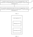
- FIG. 5 is a schematic diagram of a control apparatus according to an embodiment of this application.
- a control apparatus 500 shown in FIG. 5 includes an obtaining unit 510 and a processing unit 520.
- the obtaining unit 510 is configured to obtain information, to determine whether a first clutch 130 is controlled in a disengaged state or an engaged state.
- the information may be a control instruction for a clutch working status that is sent by another processor to the control apparatus, and the information may alternatively be a working status of a current steering system. This is not limited in this embodiment of this application.
- the processing unit 520 is configured to control the first clutch 130 to be in a disengaged state, so that driving force is not transmitted between a first steering gear 110 and a second steering gear 120.
- the processing unit 520 is further configured to control the first clutch 130 to be in an engaged state, so that driving force is transmitted between the first steering gear 110 and the second steering gear 120.
- the first steering gear 110 includes a first transmission member 111 and a second transmission member 112 that are in a transmission connection, and the first transmission member 111 is configured to apply obtained first driving force to an outer-side wheel 114 by using the second transmission member 112; and the second steering gear 120 includes a third transmission member 121 and a fourth transmission member 122 that are in a transmission connection, the third transmission member 121 is configured to apply obtained second driving force to an inner-side wheel 124 by using the fourth transmission member 122, and the first transmission member 111 and the third transmission member 121 are connected by using the first clutch 130.
- the processing unit 520 is further configured to control the first clutch 130 to be in the engaged state, so that the first driving force obtained by the first transmission member 111 is transmitted to the third transmission member 121 by using the first clutch 130.
- a steering system includes a first driving apparatus 115, and the processing unit 520 is further configured to control the first driving apparatus 115 to provide third driving force for the second transmission member 112, to drive the second transmission member 112 to move, so that the second transmission member 112 transmits the third driving force to the first transmission member 111, and the first transmission member 111 obtains the first driving force.
- the processing unit 520 is further configured to control the first clutch 130 to be in the engaged state, so that the second driving force obtained by the third transmission member 121 is transmitted to the first transmission member 111 by using the first clutch 130.
- a steering system includes a second driving apparatus 125
- the processing unit 520 is further configured to control the second driving apparatus 125 to provide fourth driving force for the fourth transmission member 122, to drive the fourth transmission member 122 to move and transmit the fourth driving force to the third transmission member 121, so that the third transmission member 121 obtains the second driving force.
- a steering system includes a first driving apparatus 115 and a second driving apparatus 125
- the processing unit 520 is further configured to: when the first clutch 130 is in the disengaged state, control the first driving apparatus 115 to drive the second transmission member 112 to move, to control steering force applied to the outer-side wheel 114; and/or control the second driving apparatus 125 to drive the fourth transmission member 122 to move, to control steering force applied to the inner-side wheel 124.
- the first transmission member 111 is a first gear
- the second transmission member 112 is a first rack
- the third transmission member 121 is a second gear
- the fourth transmission member 122 is a second rack.
- the processing unit 520 may be a processor 620
- the obtaining unit 520 may be a communications interface 630
- the controller apparatus may further include a memory 610, specifically as shown in FIG. 6 . It should be understood that a controller 600 shown in FIG. 6 may alternatively be the foregoing controller 410.
- FIG. 6 is a schematic block diagram of a controller according to another embodiment of this application.
- a controller 600 shown in FIG. 6 may include a memory 610, a processor 620, and a communications interface 630.
- the memory 610, the processor 620, and the communications interface 630 are connected by using an internal connection path.
- the memory 610 is configured to store instructions.
- the processor 620 is configured to execute the instructions stored in the memory 610, to control an input/output interface 630 to receive/send at least some parameters of a second channel model.
- the memory 610 may be coupled to the processor 620 by using an interface, or integrated with the processor 620.
- the communications interface 630 uses a transceiver apparatus such as, but not limited to, a transceiver to implement communication between a communications device and another device or a communications network.
- the communications interface 630 may further include an input/output interface (input/output interface).
- steps in the foregoing methods may be implemented by using a hardware integrated logic circuit in the processor 620, or by using instructions in a form of software.
- the methods disclosed with reference to the embodiments of this application may be directly performed by a hardware processor, or may be performed by using a combination of hardware in the processor and a software module.
- the software module may be located in a mature storage medium in the art, for example, a random access memory, a flash memory, a read-only memory, a programmable read-only memory, an electrically erasable programmable memory, or a register.
- the storage medium is located in the memory 610, and the processor 620 reads information in the memory 610 and completes the steps in the foregoing methods in combination with hardware of the processor. To avoid repetition, details are not described herein again.
- the processor in the embodiments of this application may be a central processing unit (central processing unit, CPU).
- the processor may alternatively be another general-purpose processor, a digital signal processor (digital signal processor, DSP), an application-specific integrated circuit (application-specific integrated circuit, ASIC), a field programmable gate array (field programmable gate array, FPGA) or another programmable logic device, a discrete gate or transistor logic device, a discrete hardware component, or the like.
- the general-purpose processor may be a microprocessor, or the processor may be any conventional processor or the like.
- the memory may include a read-only memory and a random access memory, and provide instructions and data to the processor.
- a part of the processor may further include a non-volatile random access memory.
- the processor may further store information of a device type.
- the engaged state may include a fully-engaged state and a half-engaged state.
- sequence numbers of the foregoing processes do not mean execution sequences in various embodiments of this application.
- the execution sequences of the processes should be determined based on functions and internal logic of the processes, and should not be construed as any limitation on the implementation processes of the embodiments of this application.
- the driving apparatus in the embodiments of this application may be a motor or another apparatus that can provide driving force. This is not limited in the embodiments of this application.
- the disclosed system, apparatus, and method may be implemented in other manners.
- the described apparatus embodiments are merely examples.
- division into units is merely logical function division and may be other division during actual implementation.
- a plurality of units or components may be combined or integrated into another system, or some features may be ignored or not performed.
- the displayed or discussed mutual couplings or direct couplings or communication connections may be implemented through some interfaces.
- the indirect couplings or communication connections between the apparatuses or units may be implemented in electrical, mechanical, or another form.
- the units described as separate parts may or may not be physically separate, and parts displayed as units may or may not be physical units, may be located in one position, or may be distributed on a plurality of network units. Some or all of the units may be selected based on actual requirements to achieve the objectives of the solutions of the embodiments.
- function units in the embodiments of this application may be integrated into one processing unit, or each of the units may exist alone physically, or two or more units may be integrated into one unit.
- the functions When the functions are implemented in a form of a software function unit and sold or used as an independent product, the functions may be stored in a computer-readable storage medium. Based on such an understanding, the technical solutions of this application essentially, or the part contributing to the conventional technology, or some of the technical solutions may be implemented in a form of a software product.
- the computer software product is stored in a storage medium, and includes several instructions for instructing a computer device (which may be a personal computer, a server, or a network device) to perform all or some of the steps of the methods described in the embodiments of this application.
- the foregoing storage medium includes: any medium that can store program code, such as a USB flash drive, a removable hard disk, a read-only memory (read-only memory, ROM), a random access memory (random access memory, RAM), a magnetic disk, or an optical disc.
- program code such as a USB flash drive, a removable hard disk, a read-only memory (read-only memory, ROM), a random access memory (random access memory, RAM), a magnetic disk, or an optical disc.
Landscapes
- Engineering & Computer Science (AREA)
- Chemical & Material Sciences (AREA)
- Combustion & Propulsion (AREA)
- Transportation (AREA)
- Mechanical Engineering (AREA)
- Power Steering Mechanism (AREA)
- Steering Control In Accordance With Driving Conditions (AREA)
Applications Claiming Priority (1)
| Application Number | Priority Date | Filing Date | Title |
|---|---|---|---|
| PCT/CN2020/114045 WO2022051909A1 (fr) | 2020-09-08 | 2020-09-08 | Mécanisme de direction, système de direction, véhicule et procédé de commande pour système de direction |
Publications (2)
| Publication Number | Publication Date |
|---|---|
| EP4194314A1 true EP4194314A1 (fr) | 2023-06-14 |
| EP4194314A4 EP4194314A4 (fr) | 2023-09-27 |
Family
ID=75017366
Family Applications (1)
| Application Number | Title | Priority Date | Filing Date |
|---|---|---|---|
| EP20952698.7A Pending EP4194314A4 (fr) | 2020-09-08 | 2020-09-08 | Mécanisme de direction, système de direction, véhicule et procédé de commande pour système de direction |
Country Status (4)
| Country | Link |
|---|---|
| US (1) | US20230202551A1 (fr) |
| EP (1) | EP4194314A4 (fr) |
| CN (1) | CN112543727A (fr) |
| WO (1) | WO2022051909A1 (fr) |
Families Citing this family (6)
| Publication number | Priority date | Publication date | Assignee | Title |
|---|---|---|---|---|
| EP4029761B1 (fr) * | 2021-01-13 | 2024-07-17 | Volvo Truck Corporation | Système de direction de véhicule et procédé de commande d'un angle de direction d'une roue de véhicule |
| CN115959191A (zh) * | 2021-10-09 | 2023-04-14 | 蜂巢智能转向系统(江苏)有限公司保定分公司 | 转向器和具有其的车辆 |
| CN113895509B (zh) * | 2021-12-10 | 2022-03-25 | 北京理工大学深圳汽车研究院(电动车辆国家工程实验室深圳研究院) | 可切换转向模式的转向器总成和转向系统 |
| CN114275033B (zh) * | 2022-02-15 | 2023-04-14 | 一汽解放汽车有限公司 | 转向系统及车辆 |
| CN114644041B (zh) * | 2022-05-23 | 2022-10-04 | 北京理工大学深圳汽车研究院(电动车辆国家工程实验室深圳研究院) | 可切换转向方式的转向器总成、转向系统、车辆 |
| US20240227911A1 (en) * | 2023-01-06 | 2024-07-11 | Adam West | Steering system for a vehicle |
Family Cites Families (12)
| Publication number | Priority date | Publication date | Assignee | Title |
|---|---|---|---|---|
| CN100436227C (zh) * | 2003-10-02 | 2008-11-26 | 日产自动车株式会社 | 车辆转向装置 |
| JP4720362B2 (ja) * | 2005-02-14 | 2011-07-13 | トヨタ自動車株式会社 | 操舵装置 |
| CN202011420U (zh) * | 2011-04-22 | 2011-10-19 | 南京航空航天大学 | 一种适时可变传动比的电动助力转向系统 |
| CN105667578B (zh) * | 2016-01-08 | 2018-01-12 | 普天新能源(深圳)有限公司 | 转向器、汽车转向控制系统及汽车 |
| JP2018140661A (ja) * | 2017-02-27 | 2018-09-13 | 株式会社ジェイテクト | ステアリング装置及びステアリングセンサシステム |
| US10093345B1 (en) * | 2017-03-21 | 2018-10-09 | GM Global Technology Operations LLC | System and method for testing a hands-off clutch for a steering hardware-in-loop (HIL) system |
| US10633025B2 (en) * | 2017-09-26 | 2020-04-28 | Toyota Research Institute, Inc. | Systems and methods for switching between a driver mode and an autonomous driving mode for a vehicle |
| JP2019127214A (ja) * | 2018-01-26 | 2019-08-01 | 株式会社ジェイテクト | 転舵制御装置 |
| CN109334758A (zh) * | 2018-10-25 | 2019-02-15 | 舍弗勒技术股份两合公司 | 轮驱动车辆用转向器和转向系统、车辆的驱动方法 |
| CN110435756A (zh) * | 2019-09-18 | 2019-11-12 | 吉林大学 | 一种乘用车电机驱动复合线控转向系统及转向控制方法 |
| CN211196343U (zh) * | 2019-11-22 | 2020-08-07 | 吉林大学 | 乘用车多模式电机驱动线控转向系统 |
| CN111186480A (zh) * | 2020-01-17 | 2020-05-22 | 上海琪埔维半导体有限公司 | 一种转向系统 |
-
2020
- 2020-09-08 CN CN202080004447.XA patent/CN112543727A/zh active Pending
- 2020-09-08 WO PCT/CN2020/114045 patent/WO2022051909A1/fr active Application Filing
- 2020-09-08 EP EP20952698.7A patent/EP4194314A4/fr active Pending
-
2023
- 2023-03-07 US US18/179,678 patent/US20230202551A1/en active Pending
Also Published As
| Publication number | Publication date |
|---|---|
| WO2022051909A1 (fr) | 2022-03-17 |
| CN112543727A (zh) | 2021-03-23 |
| US20230202551A1 (en) | 2023-06-29 |
| EP4194314A4 (fr) | 2023-09-27 |
Similar Documents
| Publication | Publication Date | Title |
|---|---|---|
| US20230202551A1 (en) | Steering mechanism, steering system, vehicle, and control method | |
| CN106143135B (zh) | 基于直觉驾驶理念的四轮独立转向独立驱动车辆控制系统 | |
| JP6638012B2 (ja) | 車両の車線逸脱防止制御装置 | |
| US9988079B2 (en) | Independent steering mechanism of controllable hydraulic locking type for left and right wheels | |
| EP4140857B1 (fr) | Dispositif de direction de véhicule et véhicule | |
| CN209833756U (zh) | 多模式线控四轮独立转向/驱动系统 | |
| CN112172795A (zh) | 车辆泊车控制方法、装置、设备及存储介质 | |
| CN110588769A (zh) | 一种线控转向系统及其控制方法 | |
| US5383531A (en) | Turn control system for a four wheel drive vehicle | |
| CN102673555A (zh) | 具有传感转向装置的电动汽车及利用它的转向控制方法 | |
| CN114834524B (zh) | 一种多模式双余度主动转向系统总成及控制方法 | |
| JP7529904B2 (ja) | 独立型操舵機構、操舵システムおよび制御方法 | |
| CN208682909U (zh) | 一种多模式线控转向装置 | |
| JP6121627B2 (ja) | 連結式バス用アクティブステアリングシステム | |
| CN113226891A (zh) | 一种具有冗余功能的线控独立转向机构及控制方法 | |
| CN109955891B (zh) | 电动辅助转向模组与电动液压转向模组的切换控制方法 | |
| WO2024045312A1 (fr) | Mécanisme de direction, procédé de commande de direction, engin de chantier et dispositif électronique | |
| CN112238892B (zh) | 一种基于eps和ehps的转向系统及其控制方法 | |
| CN112550448A (zh) | 一种节能汽车线控转向机构及控制方法 | |
| CN112937679A (zh) | 一种四轮转向机构 | |
| CN111923995B (zh) | 一种电液智能多冗余线控转向系统及其自适应控制方法 | |
| CN217260268U (zh) | 一种转向系统和车辆 | |
| KR102770460B1 (ko) | 카고 트레일러 rws 제어 방법 및 장치 | |
| CN215399099U (zh) | 一种三轮车 | |
| CN215921872U (zh) | 一种机器人底盘控制装置 |
Legal Events
| Date | Code | Title | Description |
|---|---|---|---|
| STAA | Information on the status of an ep patent application or granted ep patent |
Free format text: STATUS: THE INTERNATIONAL PUBLICATION HAS BEEN MADE |
|
| PUAI | Public reference made under article 153(3) epc to a published international application that has entered the european phase |
Free format text: ORIGINAL CODE: 0009012 |
|
| STAA | Information on the status of an ep patent application or granted ep patent |
Free format text: STATUS: REQUEST FOR EXAMINATION WAS MADE |
|
| 17P | Request for examination filed |
Effective date: 20230309 |
|
| AK | Designated contracting states |
Kind code of ref document: A1 Designated state(s): AL AT BE BG CH CY CZ DE DK EE ES FI FR GB GR HR HU IE IS IT LI LT LU LV MC MK MT NL NO PL PT RO RS SE SI SK SM TR |
|
| A4 | Supplementary search report drawn up and despatched |
Effective date: 20230829 |
|
| RIC1 | Information provided on ipc code assigned before grant |
Ipc: B62D 5/00 20060101ALI20230823BHEP Ipc: B62D 7/20 20060101ALI20230823BHEP Ipc: B62D 3/12 20060101AFI20230823BHEP |
|
| DAV | Request for validation of the european patent (deleted) | ||
| DAX | Request for extension of the european patent (deleted) | ||
| STAA | Information on the status of an ep patent application or granted ep patent |
Free format text: STATUS: EXAMINATION IS IN PROGRESS |
|
| RAP1 | Party data changed (applicant data changed or rights of an application transferred) |
Owner name: SHENZHEN YINWANG INTELLIGENTTECHNOLOGIES CO., LTD. |
|
| 17Q | First examination report despatched |
Effective date: 20241220 |