EP4180382A1 - Chilled n2 infused beverage dispensing system and method to prepare and dispense a chilled n2 infused beverage - Google Patents
Chilled n2 infused beverage dispensing system and method to prepare and dispense a chilled n2 infused beverage Download PDFInfo
- Publication number
- EP4180382A1 EP4180382A1 EP23150943.1A EP23150943A EP4180382A1 EP 4180382 A1 EP4180382 A1 EP 4180382A1 EP 23150943 A EP23150943 A EP 23150943A EP 4180382 A1 EP4180382 A1 EP 4180382A1
- Authority
- EP
- European Patent Office
- Prior art keywords
- beverage
- liquid
- gas
- membrane unit
- chilled
- Prior art date
- Legal status (The legal status is an assumption and is not a legal conclusion. Google has not performed a legal analysis and makes no representation as to the accuracy of the status listed.)
- Pending
Links
- 235000013361 beverage Nutrition 0.000 title claims abstract description 287
- 238000000034 method Methods 0.000 title claims description 47
- 239000007789 gas Substances 0.000 claims abstract description 242
- 239000007788 liquid Substances 0.000 claims abstract description 210
- 239000012528 membrane Substances 0.000 claims abstract description 122
- IJGRMHOSHXDMSA-UHFFFAOYSA-N Atomic nitrogen Chemical compound N#N IJGRMHOSHXDMSA-UHFFFAOYSA-N 0.000 claims abstract description 87
- 229910052757 nitrogen Inorganic materials 0.000 claims abstract description 33
- 229910001873 dinitrogen Inorganic materials 0.000 claims abstract description 19
- 230000001105 regulatory effect Effects 0.000 claims abstract description 12
- 238000012546 transfer Methods 0.000 claims description 22
- 238000001816 cooling Methods 0.000 claims description 18
- 238000005057 refrigeration Methods 0.000 claims description 18
- 238000001914 filtration Methods 0.000 claims description 10
- 241001122767 Theaceae Species 0.000 claims description 8
- 230000008878 coupling Effects 0.000 claims description 7
- 238000010168 coupling process Methods 0.000 claims description 7
- 238000005859 coupling reaction Methods 0.000 claims description 7
- 238000005086 pumping Methods 0.000 claims description 7
- 239000003792 electrolyte Substances 0.000 claims description 5
- 235000011389 fruit/vegetable juice Nutrition 0.000 claims description 5
- 235000012171 hot beverage Nutrition 0.000 claims description 4
- 238000010926 purge Methods 0.000 claims description 2
- 238000011144 upstream manufacturing Methods 0.000 claims 2
- CURLTUGMZLYLDI-UHFFFAOYSA-N Carbon dioxide Chemical compound O=C=O CURLTUGMZLYLDI-UHFFFAOYSA-N 0.000 description 61
- 229910002092 carbon dioxide Inorganic materials 0.000 description 56
- 239000000796 flavoring agent Substances 0.000 description 14
- 235000019634 flavors Nutrition 0.000 description 14
- 239000000203 mixture Substances 0.000 description 14
- 238000010586 diagram Methods 0.000 description 10
- 239000012510 hollow fiber Substances 0.000 description 8
- 239000006260 foam Substances 0.000 description 7
- 230000000694 effects Effects 0.000 description 6
- 235000013405 beer Nutrition 0.000 description 5
- 239000001569 carbon dioxide Substances 0.000 description 5
- 239000011521 glass Substances 0.000 description 5
- 238000001802 infusion Methods 0.000 description 5
- 239000000463 material Substances 0.000 description 4
- CDBYLPFSWZWCQE-UHFFFAOYSA-L Sodium Carbonate Chemical compound [Na+].[Na+].[O-]C([O-])=O CDBYLPFSWZWCQE-UHFFFAOYSA-L 0.000 description 3
- 235000014171 carbonated beverage Nutrition 0.000 description 3
- 238000010276 construction Methods 0.000 description 3
- 239000012530 fluid Substances 0.000 description 3
- 239000000047 product Substances 0.000 description 3
- 239000007787 solid Substances 0.000 description 3
- 230000015572 biosynthetic process Effects 0.000 description 2
- 230000035622 drinking Effects 0.000 description 2
- 238000012986 modification Methods 0.000 description 2
- 230000004048 modification Effects 0.000 description 2
- JCXJVPUVTGWSNB-UHFFFAOYSA-N nitrogen dioxide Inorganic materials O=[N]=O JCXJVPUVTGWSNB-UHFFFAOYSA-N 0.000 description 2
- 239000012466 permeate Substances 0.000 description 2
- 238000002360 preparation method Methods 0.000 description 2
- XLYOFNOQVPJJNP-UHFFFAOYSA-N water Substances O XLYOFNOQVPJJNP-UHFFFAOYSA-N 0.000 description 2
- 238000004354 ROESY-TOCSY relay Methods 0.000 description 1
- 230000001419 dependent effect Effects 0.000 description 1
- 238000005516 engineering process Methods 0.000 description 1
- 235000013305 food Nutrition 0.000 description 1
- -1 for example Chemical compound 0.000 description 1
- 238000003780 insertion Methods 0.000 description 1
- 230000037431 insertion Effects 0.000 description 1
- 239000011344 liquid material Substances 0.000 description 1
- 238000012423 maintenance Methods 0.000 description 1
- QJGQUHMNIGDVPM-UHFFFAOYSA-N nitrogen group Chemical group [N] QJGQUHMNIGDVPM-UHFFFAOYSA-N 0.000 description 1
- 230000008569 process Effects 0.000 description 1
- 230000009467 reduction Effects 0.000 description 1
- 229910001220 stainless steel Inorganic materials 0.000 description 1
- 239000010935 stainless steel Substances 0.000 description 1
Images


Classifications
-
- B—PERFORMING OPERATIONS; TRANSPORTING
- B67—OPENING, CLOSING OR CLEANING BOTTLES, JARS OR SIMILAR CONTAINERS; LIQUID HANDLING
- B67D—DISPENSING, DELIVERING OR TRANSFERRING LIQUIDS, NOT OTHERWISE PROVIDED FOR
- B67D1/00—Apparatus or devices for dispensing beverages on draught
- B67D1/04—Apparatus utilising compressed air or other gas acting directly or indirectly on beverages in storage containers
- B67D1/0406—Apparatus utilising compressed air or other gas acting directly or indirectly on beverages in storage containers with means for carbonating the beverage, or for maintaining its carbonation
-
- A—HUMAN NECESSITIES
- A23—FOODS OR FOODSTUFFS; TREATMENT THEREOF, NOT COVERED BY OTHER CLASSES
- A23F—COFFEE; TEA; THEIR SUBSTITUTES; MANUFACTURE, PREPARATION, OR INFUSION THEREOF
- A23F3/00—Tea; Tea substitutes; Preparations thereof
-
- A—HUMAN NECESSITIES
- A23—FOODS OR FOODSTUFFS; TREATMENT THEREOF, NOT COVERED BY OTHER CLASSES
- A23F—COFFEE; TEA; THEIR SUBSTITUTES; MANUFACTURE, PREPARATION, OR INFUSION THEREOF
- A23F5/00—Coffee; Coffee substitutes; Preparations thereof
-
- A—HUMAN NECESSITIES
- A23—FOODS OR FOODSTUFFS; TREATMENT THEREOF, NOT COVERED BY OTHER CLASSES
- A23L—FOODS, FOODSTUFFS OR NON-ALCOHOLIC BEVERAGES, NOT OTHERWISE PROVIDED FOR; PREPARATION OR TREATMENT THEREOF
- A23L2/00—Non-alcoholic beverages; Dry compositions or concentrates therefor; Preparation or treatment thereof
- A23L2/52—Adding ingredients
- A23L2/54—Mixing with gases
-
- B—PERFORMING OPERATIONS; TRANSPORTING
- B67—OPENING, CLOSING OR CLEANING BOTTLES, JARS OR SIMILAR CONTAINERS; LIQUID HANDLING
- B67D—DISPENSING, DELIVERING OR TRANSFERRING LIQUIDS, NOT OTHERWISE PROVIDED FOR
- B67D1/00—Apparatus or devices for dispensing beverages on draught
- B67D1/0042—Details of specific parts of the dispensers
- B67D1/0057—Carbonators
- B67D1/0058—In-line carbonators
-
- B—PERFORMING OPERATIONS; TRANSPORTING
- B67—OPENING, CLOSING OR CLEANING BOTTLES, JARS OR SIMILAR CONTAINERS; LIQUID HANDLING
- B67D—DISPENSING, DELIVERING OR TRANSFERRING LIQUIDS, NOT OTHERWISE PROVIDED FOR
- B67D1/00—Apparatus or devices for dispensing beverages on draught
- B67D1/0042—Details of specific parts of the dispensers
- B67D1/0057—Carbonators
- B67D1/0061—Carbonators with cooling means
- B67D1/0066—Carbonators with cooling means outside the carbonator
-
- B—PERFORMING OPERATIONS; TRANSPORTING
- B67—OPENING, CLOSING OR CLEANING BOTTLES, JARS OR SIMILAR CONTAINERS; LIQUID HANDLING
- B67D—DISPENSING, DELIVERING OR TRANSFERRING LIQUIDS, NOT OTHERWISE PROVIDED FOR
- B67D1/00—Apparatus or devices for dispensing beverages on draught
- B67D1/0042—Details of specific parts of the dispensers
- B67D1/0057—Carbonators
- B67D1/0069—Details
- B67D1/0077—Carbonator being specially adapted for adding a second gas to the CO2
-
- B—PERFORMING OPERATIONS; TRANSPORTING
- B67—OPENING, CLOSING OR CLEANING BOTTLES, JARS OR SIMILAR CONTAINERS; LIQUID HANDLING
- B67D—DISPENSING, DELIVERING OR TRANSFERRING LIQUIDS, NOT OTHERWISE PROVIDED FOR
- B67D1/00—Apparatus or devices for dispensing beverages on draught
- B67D1/08—Details
- B67D1/0857—Cooling arrangements
-
- B—PERFORMING OPERATIONS; TRANSPORTING
- B67—OPENING, CLOSING OR CLEANING BOTTLES, JARS OR SIMILAR CONTAINERS; LIQUID HANDLING
- B67D—DISPENSING, DELIVERING OR TRANSFERRING LIQUIDS, NOT OTHERWISE PROVIDED FOR
- B67D1/00—Apparatus or devices for dispensing beverages on draught
- B67D1/08—Details
- B67D1/10—Pump mechanism
-
- A—HUMAN NECESSITIES
- A23—FOODS OR FOODSTUFFS; TREATMENT THEREOF, NOT COVERED BY OTHER CLASSES
- A23V—INDEXING SCHEME RELATING TO FOODS, FOODSTUFFS OR NON-ALCOHOLIC BEVERAGES AND LACTIC OR PROPIONIC ACID BACTERIA USED IN FOODSTUFFS OR FOOD PREPARATION
- A23V2002/00—Food compositions, function of food ingredients or processes for food or foodstuffs
-
- B—PERFORMING OPERATIONS; TRANSPORTING
- B67—OPENING, CLOSING OR CLEANING BOTTLES, JARS OR SIMILAR CONTAINERS; LIQUID HANDLING
- B67D—DISPENSING, DELIVERING OR TRANSFERRING LIQUIDS, NOT OTHERWISE PROVIDED FOR
- B67D1/00—Apparatus or devices for dispensing beverages on draught
- B67D2001/0091—Component storage means
- B67D2001/0092—Containers for gas, for, e.g. CO2, N2
-
- B—PERFORMING OPERATIONS; TRANSPORTING
- B67—OPENING, CLOSING OR CLEANING BOTTLES, JARS OR SIMILAR CONTAINERS; LIQUID HANDLING
- B67D—DISPENSING, DELIVERING OR TRANSFERRING LIQUIDS, NOT OTHERWISE PROVIDED FOR
- B67D1/00—Apparatus or devices for dispensing beverages on draught
- B67D1/04—Apparatus utilising compressed air or other gas acting directly or indirectly on beverages in storage containers
- B67D2001/0475—Type of gas or gas mixture used, other than pure CO2
- B67D2001/0487—Mixture of gases, e.g. N2 + CO2
Definitions
- the present invention relates to a dispense system to infuse a chilled beverage with N 2 or a mixed gas and then dispense that gas infused chilled beverage into a receiver such as a glass or mug so that the dispensed chilled beverage has a flavor, odor and appearance enhanced by the gas infusion and beverage dispensation process.
- N 2 gas to store and dispense carbonated beverages such as beer and soda is conventionally known and is described, for example in U.S. 6,138,995 and in U.S. 8,438,969 .
- infusion of other non-carbonated beverages such as coffee or tea and provision of that product as a chilled beverage to a consumer from a dispensing unit has not been successfully accomplished to date.
- a chilled beverage such as tea or coffee is provided with unique flavor and appearance by N 2 infusion and there is a need for a system, preferably a self-contained unit that prepares and dispenses chilled N 2 or N 2 /CO 2 infused beverages both in a commercial utility and in a residential kitchen.
- the system In addition to flavor and appearance enhancement of the chilled beverage, the system must also be cost effective and user friendly for utilization and maintenance.
- the first embodiment of which includes a system for dispensing a cooled beverage comprising: a beverage tank capable of being pressurized; a controlled pressurized supply of pure nitrogen gas or a mixed nitrogen gas such as, for example, a mixture of 25 % carbon dioxide and 75 % nitrogen; a liquid/gas contactor membrane unit; a diaphragm pump; and a beverage faucet attached downstream to the liquid/gas contactor membrane unit; wherein regulated pressure nitrogen gas or mixed gas is fed via supply lines to the liquid/gas contactor membrane unit, the diaphragm pump and through a secondary regulator to the beverage tank, the diaphragm pump is arranged via transfer lines to transfer beverage from the beverage tank to the liquid/gas contactor membrane, and the gas feed supply line to the liquid/gas contactor membrane unit comprises a check valve preventing liquid flow from the liquid/gas contactor membrane unit into the gas supply line.
- a beverage tank capable of being pressurized
- a controlled pressurized supply of pure nitrogen gas or a mixed nitrogen gas such as, for example,
- the beverage tank may be replaced with a bag in box liquid container which is not pressurized and therefore the system may be simplified because a secondary regulator and gas supply to the beverage container are not necessary.
- the present invention includes a system for dispensing a cooled beverage, comprising: a bag-in-box beverage container; a controlled pressurized supply of a gas comprising at least 50% by weight nitrogen; a liquid/gas contactor membrane unit; a diaphragm pump; and a beverage faucet attached downstream to the liquid/gas contactor membrane unit; wherein regulated pressure nitrogen gas is fed via supply lines to the liquid/gas contactor membrane unit and the diaphragm pump, the diaphragm pump is arranged via transfer lines to transfer beverage from the bag-in-box beverage container to the liquid/gas contactor membrane unit, and the nitrogen feed supply line to the liquid/gas contactor membrane unit comprises a check valve preventing liquid flow from the liquid/gas contactor membrane unit into the pressurized gas supply line.
- the system includes a chiller or refrigeration unit that cools at least the beverage tank or bag in box container and preferably cools the beverage tank or bag in box container, liquid/gas contactor membrane unit and the dispense tower.
- the nitrogen gas supply is at least 99.5 % N 2 .
- the system is a self-contained unit which is suitable for utility in a commercial facility such as a restaurant or coffee shop.
- the present invention includes a method for dispensing a chilled liquid from the systems of the first and second embodiments and further aspects thereof.
- the method comprises: charging a beverage to the beverage tank or bag-in-box container; opening the gas supply regulator on the gas supply to feed N 2 or N 2 /CO 2 mixture to the liquid/gas contactor membrane unit, diaphragm pump and the secondary gas regulator; adjusting the gas regulator to supply N 2 or N 2 /CO 2 mixture at a pressure of from 20 to 70 psi at the liquid/gas contactor membrane unit and diaphragm pump; adjusting the secondary regulator to pressurize the beverage tank to 10-12 psi; pumping the chilled liquid from the beverage tank through the diaphragm pump to the liquid/gas contactor membrane unit; contacting the chilled liquid with N 2 or N 2 /CO 2 mixture in the liquid/gas contactor membrane unit to disperse and/or dissolve the N 2 or N 2 /CO 2 in the liquid to obtain a N 2 gas infused liquid; and dispensing the N 2
- the chilled beverage is coffee that is cooled to a temperature of 34 to 37°F and infused with 20 to 50 ppm N 2 .
- the beverage faucet is a slow pour faucet optionally equipped with a restrictor nozzle or restrictor plate.
- beverage means any noncarbonated aqueous liquid material that is a homogeneous liquid substantially free of solids having a flavor due to dissolved components.
- dispensing of the chilled beverage means opening a faucet of the system to allow the chilled N 2 or N 2 /CO 2 infused beverage to flow from the system into a receiver such as a glass, mug or other drinking container.
- a faucet of the system to allow the chilled N 2 or N 2 /CO 2 infused beverage to flow from the system into a receiver such as a glass, mug or other drinking container.
- gas infused will be employed to describe either N 2 or N 2 /CO 2 infused beverage. If an embodiment is directed specifically to a N 2 /CO 2 mixture or specifically to only N 2 infusion, the actual gas composition is explicitly disclosed.
- Dispensing of the gas infused chilled beverage is an element of the present invention wherein reduction of pressure on the gas infused beverage allows escape of infused gas and results in unique properties which distinguishes the dispensed beverage by enhancement of the beverage's flavor and/or appearance.
- nitrogen, nitrogen gas, N 2 and N 2 gas are used interchangeably and convey the same meaning unless otherwise specified.
- mixed gas is used to describe a gas mixture containing at least 50% N 2 with the remainder being carbon dioxide.
- the present inventors have recognized that beverages other than carbonated drinks such as beer and soda may have enhanced flavor and attractive appearance as a result of infusing the beverage with nitrogen or a mixture of nitrogen and carbon dioxide.
- beverages other than carbonated drinks such as beer and soda may have enhanced flavor and attractive appearance as a result of infusing the beverage with nitrogen or a mixture of nitrogen and carbon dioxide.
- a dispense system to provide a gas infused chilled beverage in such a way to present the beverage with a unique and appealing flavor and appearance.
- the present invention provides a system for dispensing a cooled beverage, comprising: a beverage tank capable of being pressurized (2); a controlled pressurized gas supply of pure nitrogen gas or a mixed gas (4); a gas supply assembly (9), a liquid/gas contactor membrane unit (8); a beverage pump (10); and a beverage faucet (3) located in a dispense tower (1) attached downstream in beverage flow to the liquid/gas contactor membrane unit via line (11) wherein regulated pressure gas is fed via supply lines to the liquid/gas contactor membrane unit (12), the beverage pump (13) and through a secondary regulator (7) to the beverage tank (14).
- the beverage pump is arranged via a transfer line (15) to transfer beverage from the beverage tank to the liquid/gas contactor membrane unit and from the liquid/gas contactor to the tower assembly (11).
- the gas feed supply line (12) to the liquid/gas contactor membrane unit comprises a check valve (6) preventing liquid flow from the liquid/gas contactor membrane unit via gas inlet (23) into the gas supply line.
- the chilled beverage is pumped into the liquid/gas contactor via beverage inlet (24) and the gas infused beverage exits the liquid/gas contactor at beverage outlet (22).
- the beverage tank may be connected to the gas feed line and the feed line to the pump via quick connect couplings (5) well known in the industry.
- the system may preferably incorporate an inline strainer and/or filtration unit (not shown in Fig. (1 ) in the beverage line from the beverage tank to the pump or in the line from the pump to the liquid/gas contactor membrane unit in order to protect the gas permeable membranes of the liquid/gas contactor membrane unit the filtration from solids which may be present in the beverage.
- an inline strainer and/or filtration unit not shown in Fig. (1 ) in the beverage line from the beverage tank to the pump or in the line from the pump to the liquid/gas contactor membrane unit in order to protect the gas permeable membranes of the liquid/gas contactor membrane unit the filtration from solids which may be present in the beverage.
- the beverage container capable of being pressurized is replaced with a bag in box beverage container (16).
- the bag in box modification simplifies the system in that pressurization of the beverage container is not necessary and therefore there is no need for a gas line to the container or secondary gas regulator to control the pressure of that line.
- the pump (10) transfers the beverage to the liquid/gas contactor membrane unit.
- Bag in box containers are commercially available in a range of volume sizes and materials of construction. Any suitable container of volume size convenient to the intended application may be employed. Generally, a container of 1 to 5 gallons is employed based on convenience of handling and size and structure of the refrigeration system to be employed. However, systems constructed for high volume dispense may be larger, for example 10 gallons or more.
- the box component of the container may be corrugated cardboard while the bag may be constructed of any material accepted for use in the food and beverage industry.
- Figs. 1 and 2 schematically show the arrangement of the fundamental components of the dispense systems of the present invention.
- secondary components such as safety regulators, valves, couplings, harnesses, support structure and other functional components known to one of skill in the beverage dispense technology may be incorporated in the system.
- Such commercial arrangements are included in the present invention as long as the structural components and arrangements disclosed herein are present.
- the faucet (3) shown in Figs. 1 , 2 and 6 may be a slow pour faucet designed to dispense the chilled gas infused liquid at a controlled rate to allow foam formation upon dispense and provide the unique flavor and appearance associated with the product obtained via dispense from the system of this invention.
- Commercially available faucets typically employed to tap beer are suitable for use as the faucet (3).
- Fig. 6 shows a schematic diagram of a faucet tower assembly according to an embodiment of the invention.
- a restrictor nozzle (17) is inserted in the tip of the faucet to further enhance the foam formation during liquid dispense.
- Restrictor nozzles providing differing dispense characteristics are known and commercially available.
- a restrictor plate may be employed in place of or in combination with the nozzle to enhance the frothing effect of the dispense system.
- the embodiment shown in Fig. 6 also includes a tap handle (18) which may be a decorative enhancement to the system, a drip tray (19) and quick connect coupling (20) to line (11) shown in Figs. 1 and 2 .
- the tap handle, drip tray and quick connect coupling are commercial enhancements to the system and are not elements of the present invention.
- the system is arranged or constituted in a self-contained unit or dispense kit that may be conveniently shipped to and placed in a commercial establishment for preparation and dispensation of specialty gas infused chilled beverages.
- the system may or may not include a chilling or refrigeration unit capable of cooling the system components and beverage therein to a temperature less than ambient or room temperature.
- a chilling or refrigeration unit capable of cooling the system components and beverage therein to a temperature less than ambient or room temperature.
- the cooling capability is not included in the system provision to maintain the beverage in a cooled state may be made according to methods known to one of ordinary skill in the art.
- the self-contained unit provides a user friendly and convenient chilled gas infused beverage preparation and dispensing unit especially suited for coffee bars, cafeterias, restaurants and other commercial establishments where beverages are served.
- the present invention provides a kit of the above described components that includes a mounting panel housing which attaches to a wall or panel and mounts some or all of the system components to the wall.
- Fig. 3 shows a schematic diagram of one possible wall mount arrangement of the kit assembly.
- the chilling or refrigeration system is capable to cool the system and the beverage therein to approximately 36°F although the choice of temperature will be dependent upon the beverage being handled in the system and the flavor and appearance sought.
- Chilling or refrigeration systems suitable for the system of the present invention are commercially available.
- One particularly preferred system is an IOWA ROTO CAST "BREEZER” cylinder shaped refrigeration unit that may conveniently contain the components of the system.
- the beverage tank may be any pressurizable tank constructed of a material suitable for contact with beverages for human consumption. Materials of construction may include stainless steel or a plastic.
- the volume of the tank is not limited. In preferred embodiments wherein the system is a self-contained unit the volume of the beverage tank may be from 2 quarts to 5 gallons.
- the nitrogen supply may be a N 2 /CO 2 mixture having at least 50 % by weight N 2 or may be essentially pure nitrogen having a N 2 content of at least 99.5 % by weight. Grades of nitrogen containing differing content of carbon dioxide within this range may be employed to impart varying flavor and appearance effects to the dispensed beverage.
- the nitrogen or mixed gas is supplied via a gas regulator valve through a pressure rated supply line containing a "T" connection to both the liquid/gas contactor membrane unit and the diaphragm pump as indicated in Fig. 1 .
- a gas regulator valve through a pressure rated supply line containing a "T" connection to both the liquid/gas contactor membrane unit and the diaphragm pump as indicated in Fig. 1 .
- the pressure of the chilled beverage pumped into the liquid/gas contactor membrane unit and the pressure of the N 2 or N 2 /CO 2 gas in the liquid/gas contactor membrane unit are controlled by the regulator on the supply tank.
- the diaphragm pump may be any appropriately sized diaphragm pump constructed for transfer of liquids for human consumption. Pumps suitable for this use are commercially available and as one example, a "SHURFLO BEER ACE" diaphragm pump may be noted.
- the beverage tank is pressurized with N 2 or mixed gas that is supplied via a secondary regulator as shown in Fig. 1 .
- the pressure in the beverage tank is regulated to be lower than the pressure of the N 2 or N 2 /CO 2 mixture supplied to the liquid/gas contactor membrane unit and diaphragm pump.
- a check valve is located in the N 2 feed line to the liquid/gas contactor membrane unit to prevent liquid "backflow" from the liquid/gas contactor membrane unit to the nitrogen gas supply.
- the liquid/gas contactor membrane unit is any suitable membrane unit containing hollow fibers such that N 2 or N 2 /CO 2 mixture gas supplied to the liquid/gas contactor membrane unit contacts the chilled beverage via passage through a gas permeable membrane and is dissolved and/or dispersed into the beverage to form a N 2 or N 2 /CO 2 infused beverage.
- a liquid/gas contactor membrane unit may be constructed of a cylindrical tube containing hollow fiber membranes. Water, aqueous liquid or a liquid having a surface tension similar to water is pumped into the space about the exterior of the hollow membranes. N 2 or N 2 /CO 2 gas at a set pressure as determined by the supply regulator is passed into the interior of the hollow fiber membrane from where it permeates through the membrane and the permeate N 2 or N 2 /CO 2 contacts the chilled beverage on the exterior of the membrane and infuses into the beverage.
- a schematic diagram of an example of a liquid/gas contactor membrane unit is shown in Fig. 3 .
- the contactor unit contains a series of hollow fiber membranes (25) arranged within a solid casing (26) and surrounded by fluid space (27).
- Liquid/gas contactor units are conventionally known and any unit which provides for gas-liquid contact across a permeable membrane may be suitably employed.
- the N 2 or N 2 mixed gas is passed through the hollow membranes while the chilled beverage is passed through the fluid space surrounding the hollow fiber membranes.
- Variation and control of the gas pressure in the interior of the hollow fiber membrane relative to the pressure of the liquid on the exterior of the hollow fiber membrane allows for differing degrees of gas infusion into the liquid.
- the gas infused beverage is transported from the liquid/gas contactor membrane unit to a dispense tower equipped with a beverage faucet.
- the beverage faucet is a slow pour faucet that dispenses the chilled gas infused beverage at a rate of from 0.1 to 5 ounces per second, preferably from 0.5 to 3 ounces per second and most preferably from 0.8 to 1.2 ounces per second. This effect and dispense rate may be further enhanced by insertion of a restrictor nozzle in the tip of the faucet as previously described.
- FIG. 4 A detailed diagram of an example of a dispense kit assembly arrangement according to the present invention is shown in Fig. 4 .
- a beverage container (2) capable of being pressurized is arranged inside a refrigeration body (29).
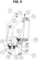
- a mixed gas or nitrogen supply tank (4) is located external to the refrigeration unit and supplies pressurized gas into the unit to the nitrogenator infuser (liquid gas contactor membrane unit) (8), the beverage pump (10) and the beverage container (2) via the secondary regulator (7) all arranged in a basket assembly (28) as shown in Fig. 5 .
- This unit may be portable if equipped with wheels or simply free-standing.
- the assembly shown in Fig. 5 includes the arrangement shown in Fig. 1 and other secondary components that may be included to enhance the safety and performance of the system as previously described.
- the component identification numbering for the special embodiment shown in Fig. 5 is not consistent with the numbering in Figs. 1 and 2 and is identified according to the following key.
- Fig. 5 The arrangement shown in Fig. 5 is assembled such that the components may be placed in a basket assembly as indicated in Fig. 4 and placed within a refrigeration unit along with the beverage container (2).
- Fig. 7 shows a standard gas supply assembly that may be utilized with the dispense system of the present invention.
- the invention is not limited to the assembly of Fig. 7 and any pressure regulated supply system providing nitrogen or nitrogen mixed gas may be employed.
- the component identification numbering for the gas supply system shown in Fig. 5 is identified according to the following key.
- the dispense unit as schematically shown in Figs. 1 and 2 may be assembled in a unit suitable for mounting on a wall or a panel of a vehicle.
- the arrangement of the component parts may be vertical or horizontal and may have components on opposite sides of the wall or panel.
- only the faucet tower may be visible on one side while the other functional components including the refrigeration unit, liquid/gas contactor, beverage container, pump and lines are out of view on the opposite side.
- the present invention includes all such arrangements as long as the schematic arrangement shown in Figs. 1 and 2 and recited in the following Claims is present.
- the present invention provides a method for preparing and dispensing a chilled gas infused liquid from a system of the present invention.
- the method comprises charging a cooled beverage to the beverage tank; opening the regulator on the N 2 or N 2 /CO 2 mixture supply to feed the gas to the liquid/gas contactor membrane unit, diaphragm pump and the secondary regulator; adjusting the supply regulator to supply N 2 or N 2 /CO 2 at a pressure of from 20 to 70 psi at the liquid/gas contactor membrane unit and beverage pump; adjusting the secondary regulator to pressurize the beverage tank to 10-12 psi; pumping the chilled liquid from the beverage tank through the diaphragm pump to the liquid/gas contactor membrane unit; contacting the chilled liquid with N 2 or N 2 /CO 2 in the liquid/gas contactor membrane unit to disperse and/or dissolve the N 2 or N 2 /CO 2 in the liquid to obtain a N 2 or N 2 /CO 2 infused liquid; and dispensing the N 2 or N 2 /CO 2 /
- the method for dispensing from a bag-in-box container differs only in that there is no gas supplied to the bag-in-box container and no pressure applied to the bag-in-box container.
- the beverage is coffee that is cooled to a temperature of 30 to 40°F, preferably 32 to 38°F and most preferably, 34 to 37°F.
- the N 2 pressure in the liquid/gas contactor membrane unit and at the beverage pump is from 20 to 70 psi and the N 2 content in the infused chilled coffee obtained is from 20 to 80 ppm, preferably 30 to 60 ppm and most preferable 40 to 50 ppm.
- the effect of the slow dispensing of the slow pour faucet is such that upon release from the system and flow to the receiver such as a serving glass, N 2 gas escapes from the chilled coffee as it cascades to the glass and results in the appearance of a head of foam or froth on the surface of the chilled coffee providing a flavor, aroma and appearance unique to the product obtained according to the present invention.
- the unique effect of the "head” obtained according to the invention may be attributable to the novel application of N 2 gas pressure applied in liquid/gas contactor membrane unit and the beverage pump.
- the beverage pump is a diaphragm pump driven by the N 2 or N 2 /CO 2 mixture from the supply tank, it may be possible in other system embodiments to control the diaphragm pump by another method or gas supply independent of the N 2 or N 2 /CO 2 mixture supply pressure.
- Diaphragm pumps are conventionally employed in industry for the pumping of beer, soda and other beverages, especially because such pumps are compatible with carbonated as well as non-carbonated liquids. Although utility of a diaphragm pump has been disclosed in these embodiments, it may be possible to employ other pumps suitable for liquids intended for human consumption.
- the relative pressure of the N 2 or N 2 /CO 2 gas in the liquid/gas contactor membrane unit and the pressure of the liquid in the liquid/gas contactor membrane unit may be varied in order to impart more unique appearance and possibly flavor enhancement to the dispensed chilled beverage.
- the ratio of the N 2 or N 2 /CO 2 gas feed pressure to the liquid pressure of the chilled beverage in the liquid/gas contactor membrane unit may be from 20/1 to 1/20 in contrast to the embodiment described above wherein because the diaphragm pump and N 2 feed to the liquid/gas contactor membrane unit are from the same supply, the ratio of the N 2 gas feed pressure to the liquid pressure of the chilled beverage in the liquid/gas contactor membrane unit is approximately 1/1.
- One of ordinary skill may learn the effect of variation of the ratio of the N 2 or N 2 /CO 2 gas feed pressure to the liquid pressure of the chilled beverage in the liquid/gas contactor membrane unit on properties of the dispensed chilled beverage through experimentation and adjust the settings as learned to obtain a N 2 or N 2 /CO 2 infused chilled beverage having unique flavor, aroma and appearance.
- the system may further contain a blast chiller unit, wherein a hot liquid such as brewed coffee or tea is first rapidly chilled or superchilled to 40°F or lower and then charged to the beverage tank.
- a blast chiller unit wherein a hot liquid such as brewed coffee or tea is first rapidly chilled or superchilled to 40°F or lower and then charged to the beverage tank.
- Such rapid chill may serve to further enhance the flavor and aroma of the N 2 or N 2 /CO 2 infused chilled beverage when dispensed to a drinking glass or other receiver.
- the present invention includes a system for dispense of a chilled beverage, comprising:
- the regulated pressure nitrogen gas may be fed via supply lines to the contacting means and the means to transfer the chilled beverage such that the pressure at the contacting means and the pressure at the transfer means is substantially the same.
- the system for dispensing the chilled beverage may further comprise a means for chilling at least the containment means and the liquid/gas contacting means and may comprise a means of enclosure of the component means for chilling and as a means to arrange the system in the form of a kit.
- system for dispensing the chilled beverage may comprise a means for restricted dispense from the controlled discharge means such that gas dissolved or dispersed in the chilled beverage is released at the chilled beverage surface to form a head of foam.
Landscapes
- Engineering & Computer Science (AREA)
- Life Sciences & Earth Sciences (AREA)
- Chemical & Material Sciences (AREA)
- Food Science & Technology (AREA)
- Polymers & Plastics (AREA)
- Mechanical Engineering (AREA)
- Health & Medical Sciences (AREA)
- Nutrition Science (AREA)
- Devices For Dispensing Beverages (AREA)
- Non-Alcoholic Beverages (AREA)
- Tea And Coffee (AREA)
Abstract
Description
- This application claims priority to
U.S. Provisional Application No. 61/993,700, filed May 15, 2014 - The present invention relates to a dispense system to infuse a chilled beverage with N2 or a mixed gas and then dispense that gas infused chilled beverage into a receiver such as a glass or mug so that the dispensed chilled beverage has a flavor, odor and appearance enhanced by the gas infusion and beverage dispensation process.
- The use of N2 gas to store and dispense carbonated beverages such as beer and soda is conventionally known and is described, for example in
U.S. 6,138,995 and inU.S. 8,438,969 . However, infusion of other non-carbonated beverages such as coffee or tea and provision of that product as a chilled beverage to a consumer from a dispensing unit has not been successfully accomplished to date. - A chilled beverage such as tea or coffee is provided with unique flavor and appearance by N2 infusion and there is a need for a system, preferably a self-contained unit that prepares and dispenses chilled N2 or N2/CO2 infused beverages both in a commercial utility and in a residential kitchen. In addition to flavor and appearance enhancement of the chilled beverage, the system must also be cost effective and user friendly for utilization and maintenance.
- This and other objects are achieved by the present invention, the first embodiment of which includes a system for dispensing a cooled beverage, comprising: a beverage tank capable of being pressurized; a controlled pressurized supply of pure nitrogen gas or a mixed nitrogen gas such as, for example, a mixture of 25 % carbon dioxide and 75 % nitrogen; a liquid/gas contactor membrane unit; a diaphragm pump; and a beverage faucet attached downstream to the liquid/gas contactor membrane unit; wherein regulated pressure nitrogen gas or mixed gas is fed via supply lines to the liquid/gas contactor membrane unit, the diaphragm pump and through a secondary regulator to the beverage tank, the diaphragm pump is arranged via transfer lines to transfer beverage from the beverage tank to the liquid/gas contactor membrane, and the gas feed supply line to the liquid/gas contactor membrane unit comprises a check valve preventing liquid flow from the liquid/gas contactor membrane unit into the gas supply line.
- In a second embodiment of the present invention, the beverage tank may be replaced with a bag in box liquid container which is not pressurized and therefore the system may be simplified because a secondary regulator and gas supply to the beverage container are not necessary. Thus, the present invention includes a system for dispensing a cooled beverage, comprising: a bag-in-box beverage container; a controlled pressurized supply of a gas comprising at least 50% by weight nitrogen; a liquid/gas contactor membrane unit; a diaphragm pump; and a beverage faucet attached downstream to the liquid/gas contactor membrane unit; wherein regulated pressure nitrogen gas is fed via supply lines to the liquid/gas contactor membrane unit and the diaphragm pump, the diaphragm pump is arranged via transfer lines to transfer beverage from the bag-in-box beverage container to the liquid/gas contactor membrane unit, and the nitrogen feed supply line to the liquid/gas contactor membrane unit comprises a check valve preventing liquid flow from the liquid/gas contactor membrane unit into the pressurized gas supply line.
- In a further aspect of the first and second embodiments the system includes a chiller or refrigeration unit that cools at least the beverage tank or bag in box container and preferably cools the beverage tank or bag in box container, liquid/gas contactor membrane unit and the dispense tower.
- In another special aspect of the first and second embodiments, the nitrogen gas supply is at least 99.5 % N2.
- In preferred applications of the first and second embodiments, the system is a self-contained unit which is suitable for utility in a commercial facility such as a restaurant or coffee shop.
- In another embodiment, the present invention includes a method for dispensing a chilled liquid from the systems of the first and second embodiments and further aspects thereof. The method comprises: charging a beverage to the beverage tank or bag-in-box container; opening the gas supply regulator on the gas supply to feed N2 or N2/CO2 mixture to the liquid/gas contactor membrane unit, diaphragm pump and the secondary gas regulator; adjusting the gas regulator to supply N2 or N2/CO2 mixture at a pressure of from 20 to 70 psi at the liquid/gas contactor membrane unit and diaphragm pump; adjusting the secondary regulator to pressurize the beverage tank to 10-12 psi; pumping the chilled liquid from the beverage tank through the diaphragm pump to the liquid/gas contactor membrane unit; contacting the chilled liquid with N2 or N2/CO2 mixture in the liquid/gas contactor membrane unit to disperse and/or dissolve the N2 or N2/CO2 in the liquid to obtain a N2 gas infused liquid; and dispensing the N2 gas infused liquid through the beverage faucet to a receiver. Optionally the beverage may be chilled prior to charging to the beverage tank, may be chilled while in the beverage tank or chilled prior to the charge and chilled in the tank.
- When the beverage is in a bag in box container pressurization of the container is not necessary and beverage flow to the liquid/gas contactor membrane is accomplished only via the diaphragm pump.
- In one preferred aspect of the method of the present invention the chilled beverage is coffee that is cooled to a temperature of 34 to 37°F and infused with 20 to 50 ppm N2.
- In a further aspect of the embodiments of the present invention, the beverage faucet is a slow pour faucet optionally equipped with a restrictor nozzle or restrictor plate.
- The foregoing paragraphs have been provided by way of general introduction, and are not intended to limit the scope of the following claims. The described embodiments, together with further advantages, will be best understood by reference to the following detailed description taken in conjunction with the accompanying drawings.
- A more complete appreciation of the disclosure and many of the attendant advantages thereof will be readily obtained as the same becomes better understood by reference to the following detailed description when considered in connection with the accompanying drawings, wherein:
-
Fig. 1 is a schematic diagram of a system having a beverage tank according to one embodiment of the present invention. -
Fig. 2 is a schematic diagram of a system having a bag-in-box beverage container according to one embodiment of the present invention. -
Fig. 3 is a schematic diagram of a liquid/gas contactor membrane unit. -
Fig. 4 is a schematic diagram of an arrangement of a portable dispense system kit according to one embodiment of the present invention. -
Fig. 5 is a diagram of the components of the basket assembly ofFig. 4 showing possible optional structural components. -
Fig. 6 shows a diagram of a tower assembly according to an embodiment of the present invention. -
Fig. 7 shows a gas supply assembly suitable for use with a system of the present invention. - Throughout this description all ranges described include all values and sub-ranges therein, unless otherwise specified. Additionally, the indefinite article "a" or "an" carries the meaning of "one or more" throughout the description, unless otherwise specified.
- According to the present invention the term "beverage" means any noncarbonated aqueous liquid material that is a homogeneous liquid substantially free of solids having a flavor due to dissolved components.
- According to the present invention dispensing of the chilled beverage means opening a faucet of the system to allow the chilled N2 or N2/CO2 infused beverage to flow from the system into a receiver such as a glass, mug or other drinking container. Throughout the following description the term "gas infused" will be employed to describe either N2 or N2/CO2 infused beverage. If an embodiment is directed specifically to a N2/CO2 mixture or specifically to only N2 infusion, the actual gas composition is explicitly disclosed.
- Dispensing of the gas infused chilled beverage is an element of the present invention wherein reduction of pressure on the gas infused beverage allows escape of infused gas and results in unique properties which distinguishes the dispensed beverage by enhancement of the beverage's flavor and/or appearance.
- Throughout this description, the terms nitrogen, nitrogen gas, N2 and N2 gas are used interchangeably and convey the same meaning unless otherwise specified. The term mixed gas is used to describe a gas mixture containing at least 50% N2 with the remainder being carbon dioxide.
- The present inventors have recognized that beverages other than carbonated drinks such as beer and soda may have enhanced flavor and attractive appearance as a result of infusing the beverage with nitrogen or a mixture of nitrogen and carbon dioxide. Upon study of methods to disperse and dissolve nitrogen or a combination of nitrogen and carbon dioxide into a chilled beverage such as coffee, tea or other noncarbonated beverages such as juices and electrolyte drinks, for example, the inventors have designed a dispense system to provide a gas infused chilled beverage in such a way to present the beverage with a unique and appealing flavor and appearance.
- In description of the Figures that follow elements common to the schematic system will have the same number designation unless otherwise noted.
- Thus, in a first embodiment as shown schematically in
Fig. 1 , the present invention provides a system for dispensing a cooled beverage, comprising: a beverage tank capable of being pressurized (2); a controlled pressurized gas supply of pure nitrogen gas or a mixed gas (4); a gas supply assembly (9), a liquid/gas contactor membrane unit (8); a beverage pump (10); and a beverage faucet (3) located in a dispense tower (1) attached downstream in beverage flow to the liquid/gas contactor membrane unit via line (11) wherein regulated pressure gas is fed via supply lines to the liquid/gas contactor membrane unit (12), the beverage pump (13) and through a secondary regulator (7) to the beverage tank (14). The beverage pump is arranged via a transfer line (15) to transfer beverage from the beverage tank to the liquid/gas contactor membrane unit and from the liquid/gas contactor to the tower assembly (11). The gas feed supply line (12) to the liquid/gas contactor membrane unit comprises a check valve (6) preventing liquid flow from the liquid/gas contactor membrane unit via gas inlet (23) into the gas supply line. The chilled beverage is pumped into the liquid/gas contactor via beverage inlet (24) and the gas infused beverage exits the liquid/gas contactor at beverage outlet (22). For convenience and ease of beverage replacement or renewal, the beverage tank may be connected to the gas feed line and the feed line to the pump via quick connect couplings (5) well known in the industry. - The system may preferably incorporate an inline strainer and/or filtration unit (not shown in
Fig. (1 ) in the beverage line from the beverage tank to the pump or in the line from the pump to the liquid/gas contactor membrane unit in order to protect the gas permeable membranes of the liquid/gas contactor membrane unit the filtration from solids which may be present in the beverage. - In a modification of the first embodiment as shown schematically in
Fig. 2 , the beverage container capable of being pressurized is replaced with a bag in box beverage container (16). The bag in box modification simplifies the system in that pressurization of the beverage container is not necessary and therefore there is no need for a gas line to the container or secondary gas regulator to control the pressure of that line. The pump (10) transfers the beverage to the liquid/gas contactor membrane unit. - Bag in box containers are commercially available in a range of volume sizes and materials of construction. Any suitable container of volume size convenient to the intended application may be employed. Generally, a container of 1 to 5 gallons is employed based on convenience of handling and size and structure of the refrigeration system to be employed. However, systems constructed for high volume dispense may be larger, for example 10 gallons or more. The box component of the container may be corrugated cardboard while the bag may be constructed of any material accepted for use in the food and beverage industry.
-
Figs. 1 and2 schematically show the arrangement of the fundamental components of the dispense systems of the present invention. However, in the construction of commercial functional units secondary components such as safety regulators, valves, couplings, harnesses, support structure and other functional components known to one of skill in the beverage dispense technology may be incorporated in the system. Such commercial arrangements are included in the present invention as long as the structural components and arrangements disclosed herein are present. - The faucet (3) shown in
Figs. 1 ,2 and6 may be a slow pour faucet designed to dispense the chilled gas infused liquid at a controlled rate to allow foam formation upon dispense and provide the unique flavor and appearance associated with the product obtained via dispense from the system of this invention. Commercially available faucets typically employed to tap beer are suitable for use as the faucet (3). -
Fig. 6 shows a schematic diagram of a faucet tower assembly according to an embodiment of the invention. In a highly preferred aspect of the invention a restrictor nozzle (17) is inserted in the tip of the faucet to further enhance the foam formation during liquid dispense. Restrictor nozzles providing differing dispense characteristics are known and commercially available. Additionally, a restrictor plate may be employed in place of or in combination with the nozzle to enhance the frothing effect of the dispense system. The embodiment shown inFig. 6 also includes a tap handle (18) which may be a decorative enhancement to the system, a drip tray (19) and quick connect coupling (20) to line (11) shown inFigs. 1 and2 . The tap handle, drip tray and quick connect coupling are commercial enhancements to the system and are not elements of the present invention. - In preferred embodiments the system is arranged or constituted in a self-contained unit or dispense kit that may be conveniently shipped to and placed in a commercial establishment for preparation and dispensation of specialty gas infused chilled beverages. The system may or may not include a chilling or refrigeration unit capable of cooling the system components and beverage therein to a temperature less than ambient or room temperature. However, if the cooling capability is not included in the system provision to maintain the beverage in a cooled state may be made according to methods known to one of ordinary skill in the art.
- The self-contained unit provides a user friendly and convenient chilled gas infused beverage preparation and dispensing unit especially suited for coffee bars, cafeterias, restaurants and other commercial establishments where beverages are served. In a special embodiment the present invention provides a kit of the above described components that includes a mounting panel housing which attaches to a wall or panel and mounts some or all of the system components to the wall.
Fig. 3 shows a schematic diagram of one possible wall mount arrangement of the kit assembly. - The chilling or refrigeration system is capable to cool the system and the beverage therein to approximately 36°F although the choice of temperature will be dependent upon the beverage being handled in the system and the flavor and appearance sought. Chilling or refrigeration systems suitable for the system of the present invention are commercially available. One particularly preferred system is an IOWA ROTO CAST "BREEZER" cylinder shaped refrigeration unit that may conveniently contain the components of the system.
- The beverage tank may be any pressurizable tank constructed of a material suitable for contact with beverages for human consumption. Materials of construction may include stainless steel or a plastic. The volume of the tank is not limited. In preferred embodiments wherein the system is a self-contained unit the volume of the beverage tank may be from 2 quarts to 5 gallons.
- The nitrogen supply may be a N2/CO2 mixture having at least 50 % by weight N2 or may be essentially pure nitrogen having a N2 content of at least 99.5 % by weight. Grades of nitrogen containing differing content of carbon dioxide within this range may be employed to impart varying flavor and appearance effects to the dispensed beverage.
- The nitrogen or mixed gas is supplied via a gas regulator valve through a pressure rated supply line containing a "T" connection to both the liquid/gas contactor membrane unit and the diaphragm pump as indicated in
Fig. 1 . In this manner the pressure of the chilled beverage pumped into the liquid/gas contactor membrane unit and the pressure of the N2 or N2/CO2 gas in the liquid/gas contactor membrane unit are controlled by the regulator on the supply tank. - The diaphragm pump may be any appropriately sized diaphragm pump constructed for transfer of liquids for human consumption. Pumps suitable for this use are commercially available and as one example, a "SHURFLO BEER ACE" diaphragm pump may be noted.
- The beverage tank is pressurized with N2 or mixed gas that is supplied via a secondary regulator as shown in
Fig. 1 . Generally, the pressure in the beverage tank is regulated to be lower than the pressure of the N2 or N2/CO2 mixture supplied to the liquid/gas contactor membrane unit and diaphragm pump. - A check valve is located in the N2 feed line to the liquid/gas contactor membrane unit to prevent liquid "backflow" from the liquid/gas contactor membrane unit to the nitrogen gas supply.
- The liquid/gas contactor membrane unit is any suitable membrane unit containing hollow fibers such that N2 or N2/CO2 mixture gas supplied to the liquid/gas contactor membrane unit contacts the chilled beverage via passage through a gas permeable membrane and is dissolved and/or dispersed into the beverage to form a N2 or N2/CO2 infused beverage.
- In general description, a liquid/gas contactor membrane unit may be constructed of a cylindrical tube containing hollow fiber membranes. Water, aqueous liquid or a liquid having a surface tension similar to water is pumped into the space about the exterior of the hollow membranes. N2 or N2/CO2 gas at a set pressure as determined by the supply regulator is passed into the interior of the hollow fiber membrane from where it permeates through the membrane and the permeate N2 or N2/CO2 contacts the chilled beverage on the exterior of the membrane and infuses into the beverage. A schematic diagram of an example of a liquid/gas contactor membrane unit is shown in
Fig. 3 . As indicated in the cross-sectional view B-B the contactor unit contains a series of hollow fiber membranes (25) arranged within a solid casing (26) and surrounded by fluid space (27). Liquid/gas contactor units are conventionally known and any unit which provides for gas-liquid contact across a permeable membrane may be suitably employed. In one embodiment ofFig. 3 , the N2 or N2 mixed gas is passed through the hollow membranes while the chilled beverage is passed through the fluid space surrounding the hollow fiber membranes. However, it is also possible to pass the chilled beverage through the hollow fiber membranes while passing the N2 or N2 mixed gas through the fluid space. Variation and control of the gas pressure in the interior of the hollow fiber membrane relative to the pressure of the liquid on the exterior of the hollow fiber membrane allows for differing degrees of gas infusion into the liquid. - The gas infused beverage is transported from the liquid/gas contactor membrane unit to a dispense tower equipped with a beverage faucet. In a preferred embodiment, as previously described the beverage faucet is a slow pour faucet that dispenses the chilled gas infused beverage at a rate of from 0.1 to 5 ounces per second, preferably from 0.5 to 3 ounces per second and most preferably from 0.8 to 1.2 ounces per second. This effect and dispense rate may be further enhanced by insertion of a restrictor nozzle in the tip of the faucet as previously described.
- A detailed diagram of an example of a dispense kit assembly arrangement according to the present invention is shown in
Fig. 4 . InFig. 4 a beverage container (2) capable of being pressurized is arranged inside a refrigeration body (29). A mixed gas or nitrogen supply tank (4) is located external to the refrigeration unit and supplies pressurized gas into the unit to the nitrogenator infuser (liquid gas contactor membrane unit) (8), the beverage pump (10) and the beverage container (2) via the secondary regulator (7) all arranged in a basket assembly (28) as shown inFig. 5 . This unit may be portable if equipped with wheels or simply free-standing. - The assembly shown in
Fig. 5 includes the arrangement shown inFig. 1 and other secondary components that may be included to enhance the safety and performance of the system as previously described. The component identification numbering for the special embodiment shown inFig. 5 is not consistent with the numbering inFigs. 1 and2 and is identified according to the following key. - (1) liquid quick connect
- (2) gas quick connect
- (3) clean/purge valve
- (4) liquid quick connect to tower assembly
- (5) gas control valve to pump
- (6) safety gas regulator for liquid/gas contactor
- (7) secondary gas regulator
- (8) gas regulator to pump and liquid/gas contactor
- (9) connection to gas assembly
- (10) Shurflow beverage pump
- (11) beverage filter assembly
- (12) liquid/gas contactor unit
- (13) back check valve
- The arrangement shown in
Fig. 5 is assembled such that the components may be placed in a basket assembly as indicated inFig. 4 and placed within a refrigeration unit along with the beverage container (2). -
Fig. 7 shows a standard gas supply assembly that may be utilized with the dispense system of the present invention. The invention is not limited to the assembly ofFig. 7 and any pressure regulated supply system providing nitrogen or nitrogen mixed gas may be employed. - The component identification numbering for the gas supply system shown in
Fig. 5 is identified according to the following key. - (1) N2 or mixed gas tank
- (2) tank open/close valve
- (3) outlet pressure gauge
- (4) regulator adjustment control
- (5) gas volume gauge
- (6) regulator valve
- (7) gas quick connect coupling
- In another embodiment of the present invention the dispense unit as schematically shown in
Figs. 1 and2 may be assembled in a unit suitable for mounting on a wall or a panel of a vehicle. The arrangement of the component parts may be vertical or horizontal and may have components on opposite sides of the wall or panel. For example, only the faucet tower may be visible on one side while the other functional components including the refrigeration unit, liquid/gas contactor, beverage container, pump and lines are out of view on the opposite side. The present invention includes all such arrangements as long as the schematic arrangement shown inFigs. 1 and2 and recited in the following Claims is present. - In another embodiment, the present invention provides a method for preparing and dispensing a chilled gas infused liquid from a system of the present invention. The method comprises charging a cooled beverage to the beverage tank; opening the regulator on the N2 or N2/CO2 mixture supply to feed the gas to the liquid/gas contactor membrane unit, diaphragm pump and the secondary regulator; adjusting the supply regulator to supply N2 or N2/CO2 at a pressure of from 20 to 70 psi at the liquid/gas contactor membrane unit and beverage pump; adjusting the secondary regulator to pressurize the beverage tank to 10-12 psi; pumping the chilled liquid from the beverage tank through the diaphragm pump to the liquid/gas contactor membrane unit; contacting the chilled liquid with N2 or N2/CO2 in the liquid/gas contactor membrane unit to disperse and/or dissolve the N2 or N2/CO2 in the liquid to obtain a N2 or N2/CO2 infused liquid; and dispensing the N2 or N2/CO2 infused liquid through the beverage faucet at a controlled rate to a receiver.
- The method for dispensing from a bag-in-box container differs only in that there is no gas supplied to the bag-in-box container and no pressure applied to the bag-in-box container.
- In one preferred embodiment the beverage is coffee that is cooled to a temperature of 30 to 40°F, preferably 32 to 38°F and most preferably, 34 to 37°F. Further, when the beverage is coffee the N2 pressure in the liquid/gas contactor membrane unit and at the beverage pump is from 20 to 70 psi and the N2 content in the infused chilled coffee obtained is from 20 to 80 ppm, preferably 30 to 60 ppm and most preferable 40 to 50 ppm.
- The effect of the slow dispensing of the slow pour faucet is such that upon release from the system and flow to the receiver such as a serving glass, N2 gas escapes from the chilled coffee as it cascades to the glass and results in the appearance of a head of foam or froth on the surface of the chilled coffee providing a flavor, aroma and appearance unique to the product obtained according to the present invention.
- The unique effect of the "head" obtained according to the invention may be attributable to the novel application of N2 gas pressure applied in liquid/gas contactor membrane unit and the beverage pump. Although in one embodiment the beverage pump is a diaphragm pump driven by the N2 or N2/CO2 mixture from the supply tank, it may be possible in other system embodiments to control the diaphragm pump by another method or gas supply independent of the N2 or N2/CO2 mixture supply pressure.
- Diaphragm pumps are conventionally employed in industry for the pumping of beer, soda and other beverages, especially because such pumps are compatible with carbonated as well as non-carbonated liquids. Although utility of a diaphragm pump has been disclosed in these embodiments, it may be possible to employ other pumps suitable for liquids intended for human consumption.
- In an embodiment wherein the gas pressure to the diaphragm pump or other suitable beverage pump is independent of the N2 or N2/CO2 supply pressure, the relative pressure of the N2 or N2/CO2 gas in the liquid/gas contactor membrane unit and the pressure of the liquid in the liquid/gas contactor membrane unit may be varied in order to impart more unique appearance and possibly flavor enhancement to the dispensed chilled beverage. In this embodiment the ratio of the N2 or N2/CO2 gas feed pressure to the liquid pressure of the chilled beverage in the liquid/gas contactor membrane unit may be from 20/1 to 1/20 in contrast to the embodiment described above wherein because the diaphragm pump and N2 feed to the liquid/gas contactor membrane unit are from the same supply, the ratio of the N2 gas feed pressure to the liquid pressure of the chilled beverage in the liquid/gas contactor membrane unit is approximately 1/1.
- One of ordinary skill may learn the effect of variation of the ratio of the N2 or N2/CO2 gas feed pressure to the liquid pressure of the chilled beverage in the liquid/gas contactor membrane unit on properties of the dispensed chilled beverage through experimentation and adjust the settings as learned to obtain a N2 or N2/CO2 infused chilled beverage having unique flavor, aroma and appearance.
- In a further embodiment, the system may further contain a blast chiller unit, wherein a hot liquid such as brewed coffee or tea is first rapidly chilled or superchilled to 40°F or lower and then charged to the beverage tank. Such rapid chill may serve to further enhance the flavor and aroma of the N2 or N2/CO2 infused chilled beverage when dispensed to a drinking glass or other receiver.
- The above description is presented to enable a person skilled in the art to make and use the invention, and is provided in the context of a particular application and its requirements. However, one of ordinary skill will recognize that many of the functional components of the embodiments described above may be substitutable with other components having the means to conduct the same function. Such structure is included in the present invention.
- Thus in a functional description embodiment the present invention includes a system for dispense of a chilled beverage, comprising:
- a containment means for storage and supply of a chilled beverage;
- a means for providing controlled pressurized gas comprising at least 50% by weight nitrogen;
- a means for contacting a chilled beverage with the pressurized gas such that the gas is dissolved and/or dispersed in the chilled beverage;
- a beverage dispensing means attached downstream to the liquid/gas contacting means; and
- a means to transfer the chilled beverage from the containment means to the gas contacting means and further to the beverage dispensing means;
- wherein the nitrogen feed supply line to the means for liquid/gas contacting comprises a means to prevent liquid flow from the liquid/gas contacting means into the pressurized gas supply line, and
- the beverage dispensing means comprises a controlled discharge means to generate a head of foam on the discharged chilled beverage.
- In a further aspect of this embodiment, the regulated pressure nitrogen gas may be fed via supply lines to the contacting means and the means to transfer the chilled beverage such that the pressure at the contacting means and the pressure at the transfer means is substantially the same.
- The system for dispensing the chilled beverage may further comprise a means for chilling at least the containment means and the liquid/gas contacting means and may comprise a means of enclosure of the component means for chilling and as a means to arrange the system in the form of a kit.
- Further the system for dispensing the chilled beverage may comprise a means for restricted dispense from the controlled discharge means such that gas dissolved or dispersed in the chilled beverage is released at the chilled beverage surface to form a head of foam.
- The present invention is further described by the following Items 1 - 48.
-
Item 1. A system for dispensing a cooled beverage, comprising:- a beverage tank capable of being pressurized;
- a controlled pressurized supply of a gas comprising at least 50% by weight nitrogen;
- a liquid/gas contactor membrane unit;
- a diaphragm pump; and
- a beverage faucet attached downstream to the liquid/gas contactor membrane unit
- wherein
- regulated pressure nitrogen gas is fed via supply lines to the liquid/gas contactor membrane unit, the diaphragm pump and through a secondary regulator to the beverage tank,
- the diaphragm pump is arranged via transfer lines to transfer beverage from the beverage tank to the liquid/gas contactor membrane unit, and
- the nitrogen feed supply line to the liquid/gas contactor membrane unit comprises a check valve preventing liquid flow from the liquid/gas contactor membrane unit into the pressurized gas supply line.
-
Item 2. The system for dispensing a cooled liquid ofItem 1, wherein the beverage faucet is a slow pour faucet optionally fitted with a restrictor nozzle or restrictor plate that allows for release of N2 or N2/CO2 gas from the beverage when dispensed to a receiver. -
Item 3. The system for dispensing a cooled liquid ofItem 1, wherein the gas comprising nitrogen is a pure nitrogen gas having at least 99.5 % N2. -
Item 4. The system for dispensing a cooled liquid ofItem 1, wherein a pressure applied to the beverage tank is from 10 to 12 psi. -
Item 5. The system for dispensing a cooled liquid ofItem 1, further comprising a cooling or refrigeration system which is capable of cooling at least the beverage tank to a temperature from ambient temperature to 36° F. -
Item 6. The system for dispensing a cooled liquid ofItem 1, wherein the pressure of the N2 or N2/CO2 supplied to the liquid/gas contactor membrane unit and the diaphragm pump is simultaneously controlled at from 20 to 70 psi. -
Item 7. A beverage dispensing unit comprising the system for dispensing a cooled liquid ofclaim 1 and a cooling or refrigeration system in one self-contained unit. -
Item 8. The beverage dispensing unit ofItem 7, further comprising a blast chiller before the beverage tank within the self-contained unit or external to the self-contained unit. -
Item 9. The beverage dispensing unit ofItem 7, further comprising an inline strainer and/or filtration unit in the beverage line prior to the liquid/gas contactor membrane unit. -
Item 10. A method for dispensing a chilled liquid from the system ofItem 1, the method comprising:- charging a cooled beverage to the beverage tank;
- opening the regulator on the N2 or N2/CO2 supply to feed N2 or N2/CO2 to the liquid/gas contactor membrane unit, diaphragm pump and the secondary regulator;
- adjusting the regulator to supply N2 or N2/CO2 at a pressure of from 20 to 70 psi at the liquid/gas contactor membrane unit and diaphragm pump;
- adjusting the secondary regulator to pressurize the beverage tank to 10-12 psi;
- pumping the chilled liquid from the beverage tank through the diaphragm pump to the liquid/gas contactor membrane unit;
- contacting the chilled liquid with N2 or N2/CO2 in the liquid/gas contactor membrane unit to disperse and/or dissolve the N2 or N2/CO2 in the liquid to obtain a N2 or N2/CO2 infused liquid; and
- dispensing the N2 or N2/CO2 infused liquid through the beverage faucet at a controlled rate to a receiver.
-
Item 11. The method ofItem 10, wherein the beverage is coffee. -
Item 12. The method ofItem 10, wherein the controlled rate of dispensing of the beverage is from 0.1 to 5 ounces of beverage per second. -
Item 13. The method ofItem 10 further comprising chilling the beverage in the beverage tank by placing at least the beverage tank in a cooling unit. -
Item 14. The method ofItem 13, wherein the beverage is coffee and the coffee is chilled to 34 to 37 °F. -
Item 15. The method ofItem 14, wherein a content of N2 in the N2 infused coffee is from 20 to 50 ppm. -
Item 16. The method ofItem 15, wherein a dispensing rate of the chilled, nitrogen infused coffee is from 0.1 to 2 ounces per second. -
Item 17. The method ofItem 10, further comprising blast chilling a hot beverage to prepare the beverage charged to the beverage tank. -
Item 18. The method ofItem 10, further comprising passing the chilled beverage through a strainer and/or filtration unit prior to entry to the liquid/gas contactor membrane unit. -
Item 19. A chilled dispensed N2 or N2/CO2 infused beverage obtained by the method ofItem 10. -
Item 20. The chilled dispensed N2 or N2/CO2 infused beverage ofItem 19, wherein the beverage is selected from the group consisting of coffee, tea, a juice and an electrolyte drink. -
Item 21. A dispense kit, comprising at least the system ofItem 1 in a self-contained unit. -
Item 22. The dispense kit ofItem 21, wherein the self-contained unit is capable of being affixed to a wall or a panel. -
Item 23. A system for dispensing a cooled beverage, comprising:- a bag-in-box beverage container;
- a controlled pressurized supply of a gas comprising at least 50% by weight nitrogen;
- a liquid/gas contactor membrane unit;
- a diaphragm pump; and
- a beverage faucet attached downstream to the liquid/gas contactor membrane unit
- wherein
- regulated pressure nitrogen gas is fed via supply lines to the liquid/gas contactor membrane unit and the diaphragm pump,
- the diaphragm pump is arranged via transfer lines to transfer beverage from the bag-in-box beverage container to the liquid/gas contactor membrane unit, and
- the nitrogen feed supply line to the liquid/gas contactor membrane unit comprises a check valve preventing liquid flow from the liquid/gas contactor membrane unit into the pressurized gas supply line.
-
Item 24. The system for dispensing a cooled liquid ofItem 23, wherein the beverage faucet is a slow pour faucet optionally fitted with a restrictor nozzle or restrictor plate that allows for release of N2 or N2/CO2 gas from the beverage when dispensed to a receiver. -
Item 25. The system for dispensing a cooled liquid ofItem 23, wherein the gas comprising nitrogen is a pure nitrogen gas having at least 99.5 % N2. -
Item 26. The system for dispensing a cooled liquid ofItem 23, wherein no pressure is applied to the bag-in-box beverage container. -
Item 27. The system for dispensing a cooled liquid ofItem 23, further comprising a cooling or refrigeration system which is capable of cooling at least the bag-in-box beverage container to a temperature from ambient temperature to 36° F. -
Item 28. The system for dispensing a cooled liquid ofItem 23, wherein the pressure of the N2 or N2/CO2 supplied to the liquid/gas contactor membrane unit and the diaphragm pump is simultaneously controlled at from 20 to 70 psi. -
Item 29. A beverage dispensing unit comprising the system for dispensing a cooled liquid ofItem 23 and a cooling or refrigeration system in one self-contained unit. - Item 30. The beverage dispensing unit of
Item 29, further comprising a blast chiller before the bag-in-box beverage container within the self-contained unit or external to the self-contained unit. - Item 31. The beverage dispensing unit of Item 30, further comprising an inline strainer and/or filtration unit in the beverage line prior to the liquid/gas contactor membrane unit.
- Item 32. A method for dispensing a chilled liquid from the system of
Item 23, the method comprising:- charging a cooled beverage to the bag-in-box beverage container;
- opening the regulator on the N2 or N2/CO2 supply to feed N2 or N2/CO2 to the liquid/gas contactor membrane unit and the diaphragm pump;
- adjusting the regulator to supply N2 or N2/CO2 at a pressure of from 20 to 70 psi at the liquid/gas contactor membrane unit and diaphragm pump;
- pumping the chilled liquid from the bag-in-box beverage container through the diaphragm pump to the liquid/gas contactor membrane unit;
- contacting the chilled liquid with N2 or N2/CO2 in the liquid/gas contactor membrane unit to disperse and/or dissolve the N2 or N2/CO2 in the liquid to obtain a N2 or N2/CO2 infused liquid; and
- dispensing the N2 or N2/CO2 infused liquid through the beverage faucet at a controlled rate to a receiver.
- Item 33. The method of Item 32, wherein the beverage is coffee.
- Item 34. The method of Item 32, wherein the controlled rate of dispensing of the beverage is from 0.1 to 5 ounces of beverage per second.
- Item 35. The method of Item 32 further comprising chilling the beverage in the bag-in-box beverage container in a cooling unit.
- Item 36. The method of Item 32, wherein the beverage is coffee and the coffee is chilled to 34 to 37 °F.
- Item 37. The method of Item 32, wherein a content of N2 in the N2 infused coffee is from 20 to 50 ppm.
- Item 38. The method of Item 37, wherein a dispensing rate of the chilled, nitrogen infused coffee is from 0.1 to 2 ounces per second.
- Item 39. The method of Item 32, further comprising blast chilling a hot beverage to prepare the beverage charged to the beverage tank.
- Item 40. The method of Item 32, further comprising passing the chilled beverage through a strainer and/or filtration unit prior to entry to the liquid/gas contactor membrane unit.
- Item 41. A chilled dispensed N2 or N2/CO2 infused beverage obtained by the method of Item 32.
- Item 42. The chilled dispensed N2 or N2/CO2 infused beverage of Item 41, wherein the beverage is selected from the group consisting of coffee, tea, a juice and an electrolyte drink.
- Item 43. A dispense kit, comprising at least the system of
Item 23 in a self-contained unit. - Item 44. The dispense kit of Item 43, wherein the self-contained unit is capable of being affixed to a wall or a panel.
- Item 45. A system for dispensing a cooled beverage, comprising:
- a containment means for storage and supply of a chilled beverage;
- a means for providing controlled pressurized gas comprising at least 50% by weight nitrogen;
- a means for contacting a chilled beverage with a gas such that the gas is dissolved and/or dispersed in the chilled beverage;
- a beverage dispensing means attached downstream to the liquid/gas contacting means; and
- a means to transfer the chilled beverage from the containment means to the gas contacting means and further to the beverage dispensing means;
- wherein
- the nitrogen feed supply line to the means for liquid/gas contacting comprises a means to prevent liquid flow from the liquid/gas contacting means into the pressurized gas supply line, and
- the beverage dispensing means comprises a controlled discharge means to generate a head of foam on the discharged beverage.
- Item 46. The system for dispensing a chilled beverage according to Item 45, further comprising a means for chilling at least the containment means and the liquid/gas contacting means.
- Item 47. The system for dispensing a chilled beverage according to Item 45, further comprising a means for restricted dispense from the controlled discharge means such that gas dissolved or dispersed in the chilled beverage is released at the chilled beverage surface to form a head of foam.
- Item 48. The system for dispensing a chilled beverage according to Item 45, wherein the regulated pressure nitrogen gas is fed via supply lines to the contacting means and the means to transfer the chilled beverage such that the pressure at the contacting means and the pressure at the transfer means is substantially the same.
Claims (16)
- A system for dispensing a cooled beverage, comprising:a bag-in-box beverage container;a controlled pressurized supply of a gas comprising at least 50% by weight nitrogen;a liquid/gas contactor membrane unit;a diaphragm pump; anda beverage faucet attached downstream to the liquid/gas contactor membrane unitwhereinregulated pressure nitrogen gas is fed via supply lines to the liquid/gas contactor membrane unit and the diaphragm pump,the diaphragm pump is arranged via transfer lines to transfer beverage from the bag-in-box beverage container to the liquid/gas contactor membrane unit, andthe nitrogen feed supply line to the liquid/gas contactor membrane unit comprises a check valve preventing liquid flow from the liquid/gas contactor membrane unit into the pressurized gas supply line.
- The system for dispensing a cooled liquid of claim 1, wherein(i) the beverage faucet is a slow pour faucet optionally fitted with a restrictor nozzle or restrictor plate that allows for release of N2 or N2/CO2 gas from the beverage when dispensed to a receiver; or(ii) the gas comprising nitrogen is a pure nitrogen gas having at least 99.5 % N2; or(iii) no pressure is applied to the bag-in-box beverage container; or(iv) the system further comprises a cooling or refrigeration system which is capable of cooling at least the bag-in-box beverage container to a temperature from ambient temperature to 36 °F; or(v) the pressure of the N2 or N2/CO2 supplied to the liquid/gas contactor membrane unit and the diaphragm pump is simultaneously controlled at from 20 to 70 psi .
- A beverage dispensing unit comprising the system for dispensing a cooled liquid of claim 1 and a cooling or refrigeration system in one self-contained unit, preferably:
further comprising a blast chiller before the bag-in-box beverage container within the self-contained unit or external to the self-contained unit, preferably thereto further comprising an inline strainer and/or filtration unit in the beverage line prior to the liquid/gas contactor membrane unit. - A method for dispensing a chilled liquid from the system of claim 1, the method comprising:charging a cooled beverage to the bag-in-box beverage container;opening the regulator on the N2 or N2/CO2 supply to feed N2 or N2/CO2 to the liquid/gas contactor membrane unit and the diaphragm pump;adjusting the regulator to supply N2 or N2/CO2 at a pressure of from 20 to 70 psi at the liquid/gas contactor membrane unit and diaphragm pump;pumping the chilled liquid from the bag-in-box beverage container through the diaphragm pump to the liquid/gas contactor membrane unit;contacting the chilled liquid with N2 or N2/CO2 in the liquid/gas contactor membrane unit to disperse and/or dissolve the N2 or N2/CO2 in the liquid to obtain a N2 or N2/CO2 infused liquid; anddispensing the N2 or N2/CO2 infused liquid through the beverage faucet at a controlled rate to a receiver.
- The method of claim 4, wherein(i) the beverage is coffee; or(ii) the controlled rate of dispensing of the beverage is from 0.1 to 5 ounces of beverage per second; or(iii) the method further comprises chilling the beverage in the bag-in-box beverage container in a cooling unit; or(iv) the beverage is coffee and the coffee is chilled to 34 to 37 °F; or(v) a content of N2 in the N2 infused coffee is from 20 to 50 ppm, preferably wherein a dispensing rate of the chilled, nitrogen infused coffee is from 0.1 to 2 ounces per second; or(vi) the method further comprises blast chilling a hot beverage to prepare the beverage charged to the beverage tank; or(vii) the method further comprises passing the chilled beverage through a strainer and/or filtration unit prior to entry to the liquid/gas contactor membrane unit.
- A chilled dispensed N2 or N2/CO2 infused beverage obtained by the method of claim 4, preferably wherein the beverage is selected from the group consisting of coffee, tea, a juice and an electrolyte drink.
- A dispense kit, comprising at least the system of claim 1 in a self-contained unit, preferably wherein the self-contained unit is capable of being affixed to a wall or a panel.
- A system for dispensing a cooled beverage, comprising:a beverage tank capable of being pressurized;a controlled pressurized supply of a gas comprising at least 50% by weight nitrogen;a liquid/gas contactor membrane unit;a diaphragm pump; anda beverage faucet attached downstream to the liquid/gas contactor membrane unitwhereinregulated pressure nitrogen gas is fed via supply lines to the liquid/gas contactor membrane unit, the diaphragm pump and through a secondary regulator to the beverage tank,the diaphragm pump is arranged via transfer lines to transfer beverage from the beverage tank to the liquid/gas contactor membrane unit, andthe nitrogen feed supply line to the liquid/gas contactor membrane unit comprises a check valve preventing liquid flow from the liquid/gas contactor membrane unit into the pressurized gas supply line.
- The system for dispensing a cooled liquid of claim 8, wherein(i) the beverage faucet is a slow pour faucet optionally fitted with a restrictor nozzle or restrictor plate that allows for release of N2 or N2/CO2 gas from the beverage when dispensed to a receiver; or(ii) the gas comprising nitrogen is a pure nitrogen gas having at least 99.5 % N2; or(iii) a pressure applied to the beverage tank is from 10 to 12 psi ; or(iv) the system further comprises a cooling or refrigeration system which is capable of cooling at least the beverage tank to a temperature from ambient temperature to 36° F; or(v) the pressure of the N2 or N2/CO2 supplied to the liquid/gas contactor membrane unit and the diaphragm pump is simultaneously controlled at from 20 to 70 psi .
- A beverage dispensing unit comprising the system for dispensing a cooled liquid of claim 8 and a cooling or refrigeration system in one self-contained unit.
- The beverage dispensing unit of claim 10, further comprising a blast chiller before the beverage tank within the self-contained unit or external to the self-contained unit; or further comprising an inline strainer and/or filtration unit in the beverage line prior to the liquid/gas contactor membrane unit.
- A method for dispensing a chilled liquid from the system of claim 8, the method comprising:charging a cooled beverage to the beverage tank;opening the regulator on the N2 or N2/CO2 supply to feed N2 or N2/CO2 to the liquid/gas contactor membrane unit, diaphragm pump and the secondary regulator;adjusting the regulator to supply N2 or N2/CO2 at a pressure of from 20 to 70 psi at the liquid/gas contactor membrane unit and diaphragm pump;adjusting the secondary regulator to pressurize the beverage tank to 10-12 psi ;pumping the chilled liquid from the beverage tank through the diaphragm pump to the liquid/gas contactor membrane unit;contacting the chilled liquid with N2 or N2/CO2 in the liquid/gas contactor membrane unit to disperse and/or dissolve the N2 or N2/CO2 in the liquid to obtain a N2 or N2/CO2 infused liquid; anddispensing the N2 or N2/CO2 infused liquid through the beverage faucet at a controlled rate to a receiver.
- The method of claim 12, wherein(i) the beverage is coffee; or(ii) the controlled rate of dispensing of the beverage is from 0.1 to 5 ounces of beverage per second; or(iii) the method further comprises chilling the beverage in the beverage tank by placing at least the beverage tank in a cooling unit, preferably theretowherein (a) the beverage is coffee and the coffee is chilled to 34 to 37 °F; and/or:wherein (b) a content of N2 in the N2 infused coffee is from 20 to 50 ppm; and/or:wherein (c) a dispensing rate of the chilled, nitrogen infused coffee is from 0.1 to 2 ounces per second;or(iv) the method further comprises blast chilling a hot beverage to prepare the beverage charged to the beverage tank; or(v) the method further comprises passing the chilled beverage through a strainer and/or filtration unit prior to entry to the liquid/gas contactor membrane unit.
- A chilled dispensed N2 or N2/CO2 infused beverage obtained by the method of claim 12, preferably wherein the beverage is selected from the group consisting of coffee, tea, a juice and an electrolyte drink.
- A dispense kit, comprising at least the system of claim 8 in a self-contained unit, preferably wherein the self-contained unit is capable of being affixed to a wall or a panel.
- A kit, comprising:a liquid-gas contactor having a downstream line with a liquid quick connect for connection to a tower assembly;a liquid supply line upstream to the gas-liquid contactor comprising a beverage pump, a beverage filter assembly, and a quick connect coupling;a gas supply line upstream to the liquid-gas contactor and the beverage pump having a gas regulator and a gas quick connect coupling;whereina safety gas regulator is located in the gas supply line between the gas regulator and the gas-liquid contactor, anda back check valve is located in the downstream line of the gas-liquid contactor prior to the tower assembly connect, preferably
wherein the kit further comprises a secondary gas regulator between the gas regulator and the safety gas regulator, further thereto wherein the kit further comprises a purge and clean valve in the liquid supply line.
Applications Claiming Priority (3)
| Application Number | Priority Date | Filing Date | Title |
|---|---|---|---|
| US201461993700P | 2014-05-15 | 2014-05-15 | |
| EP15792647.8A EP3142959B1 (en) | 2014-05-15 | 2015-05-01 | Chilled n2 infused beverage dispensing system and method to prepare and dispense a chilled n2 infused beverage |
| PCT/US2015/028876 WO2015175244A2 (en) | 2014-05-15 | 2015-05-01 | Chilled n2 infused beverage dispensing system and method to prepare and dispense a chilled n2 infused beverage |
Related Parent Applications (2)
| Application Number | Title | Priority Date | Filing Date |
|---|---|---|---|
| EP15792647.8A Division EP3142959B1 (en) | 2014-05-15 | 2015-05-01 | Chilled n2 infused beverage dispensing system and method to prepare and dispense a chilled n2 infused beverage |
| EP15792647.8A Division-Into EP3142959B1 (en) | 2014-05-15 | 2015-05-01 | Chilled n2 infused beverage dispensing system and method to prepare and dispense a chilled n2 infused beverage |
Publications (1)
| Publication Number | Publication Date |
|---|---|
| EP4180382A1 true EP4180382A1 (en) | 2023-05-17 |
Family
ID=54480915
Family Applications (2)
| Application Number | Title | Priority Date | Filing Date |
|---|---|---|---|
| EP23150943.1A Pending EP4180382A1 (en) | 2014-05-15 | 2015-05-01 | Chilled n2 infused beverage dispensing system and method to prepare and dispense a chilled n2 infused beverage |
| EP15792647.8A Active EP3142959B1 (en) | 2014-05-15 | 2015-05-01 | Chilled n2 infused beverage dispensing system and method to prepare and dispense a chilled n2 infused beverage |
Family Applications After (1)
| Application Number | Title | Priority Date | Filing Date |
|---|---|---|---|
| EP15792647.8A Active EP3142959B1 (en) | 2014-05-15 | 2015-05-01 | Chilled n2 infused beverage dispensing system and method to prepare and dispense a chilled n2 infused beverage |
Country Status (7)
| Country | Link |
|---|---|
| US (3) | US11427456B2 (en) |
| EP (2) | EP4180382A1 (en) |
| JP (1) | JP6669728B2 (en) |
| KR (1) | KR102455329B1 (en) |
| CN (1) | CN106794977B (en) |
| CA (1) | CA2949057C (en) |
| WO (1) | WO2015175244A2 (en) |
Families Citing this family (35)
| Publication number | Priority date | Publication date | Assignee | Title |
|---|---|---|---|---|
| EP4180382A1 (en) * | 2014-05-15 | 2023-05-17 | Automatic Bar Controls, Inc. | Chilled n2 infused beverage dispensing system and method to prepare and dispense a chilled n2 infused beverage |
| US20210206617A1 (en) * | 2014-05-15 | 2021-07-08 | Automatic Bar Controls, Inc. | Selectable gas infused beverage dispensing system |
| US10785996B2 (en) | 2015-08-25 | 2020-09-29 | Cornelius, Inc. | Apparatuses, systems, and methods for inline injection of gases into liquids |
| US10477883B2 (en) | 2015-08-25 | 2019-11-19 | Cornelius, Inc. | Gas injection assemblies for batch beverages having spargers |
| ITUB20154199A1 (en) * | 2015-10-07 | 2017-04-07 | Carpigiani Group Ali Spa | MACHINE AND METHOD FOR THE REALIZATION OF LIQUID AND SEMILIQUID PRODUCTS OF THE HOT OR COLD TYPE. |
| ES2813947T3 (en) | 2015-12-09 | 2021-03-25 | Welbilt Inc | Substantially non-foaming and sparkling gas-infused beverage production hybrid system and process |
| CN105536611B (en) * | 2016-01-28 | 2018-06-29 | 绍兴起重机总厂 | It is a kind of to add water agitation system and its plus water stirring means for black tea production |
| US9623383B1 (en) * | 2016-02-25 | 2017-04-18 | Ac Distributing, Inc. | System to prepare nitrogen infused beverages |
| US9955710B2 (en) | 2016-03-16 | 2018-05-01 | Cascade And Phoenix On Tap, Llc | Systems to nitrogen-infuse and dispense beverages |
| US10730023B2 (en) * | 2016-03-16 | 2020-08-04 | Cuatro Connect Llc | Methods to nitrogen-infuse and dispense beverages |
| US10017373B2 (en) * | 2016-04-15 | 2018-07-10 | Automatic Bar Controls, Inc. | Nitrogen generator and uses thereof |
| US10688450B2 (en) | 2016-07-14 | 2020-06-23 | Espresso Amore | System and method for gas impregnation of a liquid |
| IT201600074471A1 (en) | 2016-07-15 | 2018-01-15 | Ali Group Srl Carpigiani | MACHINE AND METHOD FOR THE PRODUCTION OF LIQUID AND SEMIQUID PRODUCTS OF THE ICE CREAM, PASTRY OR RESTAURANT SECTOR. |
| KR102519052B1 (en) | 2016-07-19 | 2023-04-07 | 삼성전자주식회사 | Valve assembly and refrigerator having the same |
| EP3275834A1 (en) * | 2016-07-26 | 2018-01-31 | Anheuser-Busch InBev S.A. | Dispensing apparatus for infusing carbonated beverage liquid with ingredients and method thereof |
| IT201600100869A1 (en) | 2016-10-07 | 2018-04-07 | Ali Group Srl Carpigiani | METHOD AND CLEANING SYSTEM OF A MACHINE FOR THE REALIZATION OF LIQUID AND / OR SEMIQUINE FOODSTUFFS IN THE ICE-CREAM, PASTRY OR RESTAURANT SECTOR |
| US10252900B2 (en) * | 2016-12-07 | 2019-04-09 | Cornelius Beverage Technologies Limited | Apparatuses, systems, and methods for dispensing beverages using alcoholic concentrates |
| US11147294B2 (en) * | 2017-02-02 | 2021-10-19 | Starbucks Corporation | Method and apparatus for injecting a gas into a beverage |
| US11554352B2 (en) | 2017-02-02 | 2023-01-17 | Starbucks Corporation | Method and apparatus for injecting a gas into a beverage |
| IT201700043975A1 (en) | 2017-04-21 | 2018-10-21 | Ali Group Srl Carpigiani | MACHINE AND METHOD FOR THE PRODUCTION OF LIQUID AND SEMIQUID PRODUCTS OF THE ICE CREAM SECTOR. |
| US11134805B1 (en) | 2017-10-13 | 2021-10-05 | Off The Beaten Path Coffee, Llc | Cold brewing system and method |
| EP3505487B8 (en) | 2017-12-29 | 2023-07-12 | BWT Italia S.r.l. | Mixing valve, retro-fitting method of a dispensing device for dispensing a cooled beverage mixed with a gas, and method for dispensing a beverage mixed with said gas |
| JP7200480B2 (en) | 2018-02-06 | 2023-01-10 | 富士電機株式会社 | beverage dispenser |
| MX2020011276A (en) * | 2018-04-26 | 2021-01-08 | Pepsico Inc | Systems and methods for dispensing a beverage. |
| US10470483B1 (en) * | 2018-05-29 | 2019-11-12 | Micro Matic Usa, Inc. | Gas infusion module |
| CN113038840A (en) * | 2018-10-23 | 2021-06-25 | 洛伊·巴拉克 | Apparatus for preparing a fortified beverage |
| US11040314B2 (en) | 2019-01-08 | 2021-06-22 | Marmon Foodservice Technologies, Inc. | Apparatuses, systems, and methods for injecting gasses into beverages |
| EP3945849A4 (en) | 2019-03-26 | 2022-12-14 | Flow Control LLC. | Gas liquid absorption device (glad) with replaceable gas orifice fittings and sensors |
| WO2021046503A1 (en) * | 2019-09-06 | 2021-03-11 | Flow Control LLC | In-line gas liquid infusion smart system |
| WO2021046507A1 (en) * | 2019-09-06 | 2021-03-11 | Flow Control LLC | Infusion/mixer pump system - pump with integrated gas liquid mixing valve in an enclosure |
| US20240118022A1 (en) * | 2021-02-11 | 2024-04-11 | Bert Douglas Montgomery | Non-Electric Alcohol Fluid Chiller with the Use of Liquid Carbon Dioxide |
| KR20230165758A (en) | 2021-02-24 | 2023-12-05 | 윰 코넥트, 엘엘씨 | Automatic beverage dispenser system and method |
| CA3211955A1 (en) * | 2021-03-19 | 2022-09-22 | Vishnu Vishaal Narayan Maharaj | Selectable gas infused beverage dispensing system |
| US20230189835A1 (en) * | 2021-12-20 | 2023-06-22 | Starbucks Corporation | Widgetless canned nitrogen infused beverages |
| EP4282810B1 (en) * | 2022-05-25 | 2025-01-22 | Brita Se | Apparatus and method for enriching a liquid with gas |
Citations (8)
| Publication number | Priority date | Publication date | Assignee | Title |
|---|---|---|---|---|
| GB2247225A (en) * | 1990-08-23 | 1992-02-26 | Whitbread & Co Ltd | Method and apparatus for dispensing gasified beverages |
| EP0745329A1 (en) * | 1995-05-29 | 1996-12-04 | Sara Lee/DE N.V. | Carbonated coffee beverage |
| US6138995A (en) | 1998-03-31 | 2000-10-31 | Permea, Inc. | Dispense of beverage containing controlled levels of dissolved gas |
| GB2358145A (en) * | 2000-01-13 | 2001-07-18 | J K R Page | Dissolving a mixture of gases in a beverage |
| EP1662218A1 (en) * | 2003-07-23 | 2006-05-31 | CONDE HINOJOSA, Jose Ramon | Method and device for the rapid cooling of packaged drinks |
| DE102008012486A1 (en) * | 2008-03-04 | 2009-09-17 | Carbotek Holding Gmbh | Inline carbonization process for manufacturing a carbon dioxide-containing beverage in dispense unit, comprises mixing beverage pre-product and carbon dioxide to form a mixture flow in dispense lines of the dispense unit |
| DE102010012175A1 (en) * | 2010-03-19 | 2011-09-22 | Carbotek Holding Gmbh | Impregnating device, useful or a dispensing system, comprises an impregnator for an impregnating gas and a beverage precursor, a positive displacement pump to convey beverage precursor into impregnator, and a dosing device |
| US8438969B2 (en) | 2010-05-06 | 2013-05-14 | Dr Pepper/Seven Up, Inc. | Apparatus and method for dissolving gases in a beverage |
Family Cites Families (47)
| Publication number | Priority date | Publication date | Assignee | Title |
|---|---|---|---|---|
| US4364493A (en) | 1979-08-15 | 1982-12-21 | Arthur Guinness Son And Company (Park Royal) Limited | Beverage dispensing system |
| US4438147A (en) * | 1982-06-25 | 1984-03-20 | Societe D'assistance Technique Pour Produits Nestle S.A. | Foaming creamer and method of making same |
| US4610888A (en) | 1985-05-17 | 1986-09-09 | Anheuser-Busch Companies, Inc. | Beer foam enhancing process and apparatus |
| US4759474A (en) * | 1985-06-24 | 1988-07-26 | Everpure, Inc. | Beverage dispensing system and filter cartridge therefor |
| US4708827A (en) * | 1986-03-17 | 1987-11-24 | The Cornelius Company | Method of and apparatus for making and dispensing carbonated water with a double diaphragm pneumatic water pump |
| US4932561A (en) * | 1986-10-24 | 1990-06-12 | Boxall Stanley S | Beverage cooling and dispensing apparatus |
| GB0227941D0 (en) | 2002-11-29 | 2003-01-08 | Interbrew Sa | Beer line and flow restrictor |
| US5029733A (en) * | 1987-12-14 | 1991-07-09 | Guinness Brewing Worldwide Limited | Beverage dispensing system |
| NL9201264A (en) * | 1992-07-14 | 1994-02-01 | Dmv International Division Of | POWDER-FOAMING FOAM CREAMER. |
| US5302189A (en) | 1992-08-26 | 1994-04-12 | L'air Liquide, Societe Anonyme Pour L'etude Et L'exploitation Des Procedes Georges Claude | Membrane nitrogen gas generator with improved flexibility |
| US5353963A (en) * | 1993-06-02 | 1994-10-11 | Karma, Inc. | Post mix dispenser |
| ATE165794T1 (en) | 1993-10-12 | 1998-05-15 | Frutin Bernard D | METHOD AND DEVICE FOR IMPROVING THE QUALITY OF BEVERAGES |
| US5565149A (en) | 1995-03-15 | 1996-10-15 | Permea, Inc. | Control of dissolved gases in liquids |
| US5588984A (en) * | 1995-07-18 | 1996-12-31 | Verini; Nicholas A. | Apparatus and method to intermittently manufacture and dispense nitrogen |
| US5826432A (en) * | 1995-08-18 | 1998-10-27 | El Cold, Inc. | Blast chiller |
| GB9800904D0 (en) | 1998-01-17 | 1998-03-11 | Bass Plc | Improvements relating to the delivery of flavoured alcoholic beverages |
| GB9808022D0 (en) * | 1998-04-16 | 1998-06-17 | Bass Plc | Improvements relating to the delivery of beverages |
| US6013599A (en) * | 1998-07-15 | 2000-01-11 | Redem Corporation | Self-regenerating diesel exhaust particulate filter and material |
| US6235641B1 (en) | 1998-10-30 | 2001-05-22 | Fsi International Inc. | Method and system to control the concentration of dissolved gas in a liquid |
| US6209855B1 (en) | 1999-05-10 | 2001-04-03 | Canzone Limited | Gas/liquid mixing apparatus and method |
| EP1211217A1 (en) * | 1999-10-15 | 2002-06-05 | Richard P. Bilskie | Bottle coupler |
| JP3819213B2 (en) * | 2000-04-14 | 2006-09-06 | 三星電機株式会社 | Optical pickup |
| US6719175B2 (en) | 2001-03-07 | 2004-04-13 | Island Oasis Frozen Cocktail Co., Inc. | Draft system for beverages |
| WO2003060509A1 (en) | 2001-12-28 | 2003-07-24 | Battelle Memorial Institute | Pulse cleaning apparatus and method for analytical systems |
| US7654414B2 (en) * | 2002-02-07 | 2010-02-02 | Pall Corporation | Liquids dispensing systems and methods |
| US6905356B2 (en) * | 2002-05-16 | 2005-06-14 | Homac Mfg. Company | Electrical connector including thermoplastic elastomer material and associated methods |
| GB2425166B (en) * | 2003-01-21 | 2007-01-31 | Ebac Ltd | Coolers for use with bag-in-box containers |
| EP1477754A1 (en) * | 2003-05-15 | 2004-11-17 | Wolfgang Jobmann Gmbh | Cooling system for beverage storage with method for enforced precooling of the stored beverage |
| US20050001340A1 (en) * | 2003-05-30 | 2005-01-06 | Page John K. | Apparatus for the preparation of liquids for the dispense of beverages |
| US7422845B2 (en) | 2003-11-26 | 2008-09-09 | Boehringer Ingelheim International Gmbh | Detection of NO by using guanylyl cyclase and cGMP production as a readout system |
| US7717294B2 (en) | 2005-06-20 | 2010-05-18 | South-Tek Systems | Beverage dispensing gas consumption detection with alarm and backup operation |
| JP4850947B2 (en) * | 2006-03-29 | 2012-01-11 | カーボテック ホールディング ゲーエムベーハー | Filler |
| JP5248190B2 (en) * | 2008-05-09 | 2013-07-31 | ザ コカ・コーラ カンパニー | Beverage dispenser |
| US8133525B2 (en) * | 2008-12-18 | 2012-03-13 | Whirlpool Corporation | Liquid flow control and beverage preparation apparatuses, methods and systems |
| US8435931B2 (en) * | 2009-07-17 | 2013-05-07 | Exxonmobil Research And Engineering Company | Reduced friction lubricating oils containing functionalized carbon nanomaterials |
| KR20130124159A (en) * | 2010-05-18 | 2013-11-13 | 아크티에볼라겟트 에렉트로룩스 | Drink dispensing system and method thereof |
| WO2012100333A1 (en) | 2011-01-28 | 2012-08-02 | Evantage Technologies Llc | Apparatus, systems and methods for thin film mass transfer of nitrogen and other gases into beer and other liquids |
| EP2532232A1 (en) * | 2011-06-10 | 2012-12-12 | InterMed Discovery GmbH | Long chain glycolipids useful to avoid perishing or microbial contamination of materials |
| GB2496010B (en) | 2011-10-25 | 2017-12-13 | Headmaster Ltd | Producing or dispensing liquid products |
| US20130196030A1 (en) * | 2012-02-01 | 2013-08-01 | Anthony William Criezis | Dairy Products With Added Dairy Minerals And Methods Of Producing The Same |
| IL222023B (en) | 2012-09-20 | 2020-01-30 | The Central Bottling Company Ltd | Method for filling bottles |
| EP4180382A1 (en) * | 2014-05-15 | 2023-05-17 | Automatic Bar Controls, Inc. | Chilled n2 infused beverage dispensing system and method to prepare and dispense a chilled n2 infused beverage |
| US20210206617A1 (en) * | 2014-05-15 | 2021-07-08 | Automatic Bar Controls, Inc. | Selectable gas infused beverage dispensing system |
| GB201520053D0 (en) * | 2015-11-13 | 2015-12-30 | Hartmann Frank | An apparatus for generating and infusing a gas into a liquid drink |
| US9623383B1 (en) * | 2016-02-25 | 2017-04-18 | Ac Distributing, Inc. | System to prepare nitrogen infused beverages |
| US10017373B2 (en) * | 2016-04-15 | 2018-07-10 | Automatic Bar Controls, Inc. | Nitrogen generator and uses thereof |
| US20180317524A1 (en) * | 2017-05-04 | 2018-11-08 | Lancer Corporation | Method and apparatus for nitrogen gas infused cold brew beverages |
-
2015
- 2015-05-01 EP EP23150943.1A patent/EP4180382A1/en active Pending
- 2015-05-01 EP EP15792647.8A patent/EP3142959B1/en active Active
- 2015-05-01 KR KR1020167034912A patent/KR102455329B1/en active Active
- 2015-05-01 CA CA2949057A patent/CA2949057C/en active Active
- 2015-05-01 JP JP2017512637A patent/JP6669728B2/en active Active
- 2015-05-01 CN CN201580038242.2A patent/CN106794977B/en active Active
- 2015-05-01 WO PCT/US2015/028876 patent/WO2015175244A2/en active Application Filing
- 2015-05-07 US US14/706,191 patent/US11427456B2/en active Active
-
2016
- 2016-06-10 US US15/179,267 patent/US11167975B2/en active Active
-
2022
- 2022-06-27 US US17/850,786 patent/US11897748B2/en active Active
Patent Citations (8)
| Publication number | Priority date | Publication date | Assignee | Title |
|---|---|---|---|---|
| GB2247225A (en) * | 1990-08-23 | 1992-02-26 | Whitbread & Co Ltd | Method and apparatus for dispensing gasified beverages |
| EP0745329A1 (en) * | 1995-05-29 | 1996-12-04 | Sara Lee/DE N.V. | Carbonated coffee beverage |
| US6138995A (en) | 1998-03-31 | 2000-10-31 | Permea, Inc. | Dispense of beverage containing controlled levels of dissolved gas |
| GB2358145A (en) * | 2000-01-13 | 2001-07-18 | J K R Page | Dissolving a mixture of gases in a beverage |
| EP1662218A1 (en) * | 2003-07-23 | 2006-05-31 | CONDE HINOJOSA, Jose Ramon | Method and device for the rapid cooling of packaged drinks |
| DE102008012486A1 (en) * | 2008-03-04 | 2009-09-17 | Carbotek Holding Gmbh | Inline carbonization process for manufacturing a carbon dioxide-containing beverage in dispense unit, comprises mixing beverage pre-product and carbon dioxide to form a mixture flow in dispense lines of the dispense unit |
| DE102010012175A1 (en) * | 2010-03-19 | 2011-09-22 | Carbotek Holding Gmbh | Impregnating device, useful or a dispensing system, comprises an impregnator for an impregnating gas and a beverage precursor, a positive displacement pump to convey beverage precursor into impregnator, and a dosing device |
| US8438969B2 (en) | 2010-05-06 | 2013-05-14 | Dr Pepper/Seven Up, Inc. | Apparatus and method for dissolving gases in a beverage |
Also Published As
| Publication number | Publication date |
|---|---|
| US20150329343A1 (en) | 2015-11-19 |
| EP3142959A2 (en) | 2017-03-22 |
| US11897748B2 (en) | 2024-02-13 |
| US20170233235A2 (en) | 2017-08-17 |
| WO2015175244A2 (en) | 2015-11-19 |
| US11167975B2 (en) | 2021-11-09 |
| JP2017523097A (en) | 2017-08-17 |
| KR102455329B1 (en) | 2022-10-14 |
| CN106794977B (en) | 2020-10-16 |
| CN106794977A (en) | 2017-05-31 |
| EP3142959A4 (en) | 2018-03-21 |
| EP3142959B1 (en) | 2023-12-13 |
| US20220324691A1 (en) | 2022-10-13 |
| WO2015175244A3 (en) | 2016-01-07 |
| US20160280528A1 (en) | 2016-09-29 |
| US11427456B2 (en) | 2022-08-30 |
| CA2949057A1 (en) | 2015-11-19 |
| KR20170021243A (en) | 2017-02-27 |
| WO2015175244A4 (en) | 2016-02-18 |
| CA2949057C (en) | 2024-03-26 |
| JP6669728B2 (en) | 2020-03-18 |
Similar Documents
| Publication | Publication Date | Title |
|---|---|---|
| US11897748B2 (en) | Chilled N2 infused beverage dispensing system to prepare and dispense a chilled N2 infused beverage | |
| US10743566B2 (en) | System to prepare nitrogen infused beverages | |
| US11066287B2 (en) | Nitrogen generator and uses thereof | |
| US20210206617A1 (en) | Selectable gas infused beverage dispensing system |
Legal Events
| Date | Code | Title | Description |
|---|---|---|---|
| PUAI | Public reference made under article 153(3) epc to a published international application that has entered the european phase |
Free format text: ORIGINAL CODE: 0009012 |
|
| STAA | Information on the status of an ep patent application or granted ep patent |
Free format text: STATUS: THE APPLICATION HAS BEEN PUBLISHED |
|
| AC | Divisional application: reference to earlier application |
Ref document number: 3142959 Country of ref document: EP Kind code of ref document: P |
|
| AK | Designated contracting states |
Kind code of ref document: A1 Designated state(s): AL AT BE BG CH CY CZ DE DK EE ES FI FR GB GR HR HU IE IS IT LI LT LU LV MC MK MT NL NO PL PT RO RS SE SI SK SM TR |
|
| RIN1 | Information on inventor provided before grant (corrected) |
Inventor name: KLEINRICHERT, CHARLES |
|
| STAA | Information on the status of an ep patent application or granted ep patent |
Free format text: STATUS: REQUEST FOR EXAMINATION WAS MADE |
|
| 17P | Request for examination filed |
Effective date: 20231113 |
|
| RBV | Designated contracting states (corrected) |
Designated state(s): AL AT BE BG CH CY CZ DE DK EE ES FI FR GB GR HR HU IE IS IT LI LT LU LV MC MK MT NL NO PL PT RO RS SE SI SK SM TR |
|
| STAA | Information on the status of an ep patent application or granted ep patent |
Free format text: STATUS: EXAMINATION IS IN PROGRESS |
|
| 17Q | First examination report despatched |
Effective date: 20240807 |
|
| GRAP | Despatch of communication of intention to grant a patent |
Free format text: ORIGINAL CODE: EPIDOSNIGR1 |
|
| STAA | Information on the status of an ep patent application or granted ep patent |
Free format text: STATUS: GRANT OF PATENT IS INTENDED |