EP4167586A1 - Method for controlling a camera of a court room media system - Google Patents
Method for controlling a camera of a court room media system Download PDFInfo
- Publication number
- EP4167586A1 EP4167586A1 EP22201730.3A EP22201730A EP4167586A1 EP 4167586 A1 EP4167586 A1 EP 4167586A1 EP 22201730 A EP22201730 A EP 22201730A EP 4167586 A1 EP4167586 A1 EP 4167586A1
- Authority
- EP
- European Patent Office
- Prior art keywords
- camera
- controllable
- signal
- courtroom
- controllable camera
- Prior art date
- Legal status (The legal status is an assumption and is not a legal conclusion. Google has not performed a legal analysis and makes no representation as to the accuracy of the status listed.)
- Pending
Links
Images


Classifications
-
- H—ELECTRICITY
- H04—ELECTRIC COMMUNICATION TECHNIQUE
- H04N—PICTORIAL COMMUNICATION, e.g. TELEVISION
- H04N23/00—Cameras or camera modules comprising electronic image sensors; Control thereof
- H04N23/60—Control of cameras or camera modules
- H04N23/69—Control of means for changing angle of the field of view, e.g. optical zoom objectives or electronic zooming
-
- H—ELECTRICITY
- H04—ELECTRIC COMMUNICATION TECHNIQUE
- H04N—PICTORIAL COMMUNICATION, e.g. TELEVISION
- H04N23/00—Cameras or camera modules comprising electronic image sensors; Control thereof
- H04N23/60—Control of cameras or camera modules
- H04N23/61—Control of cameras or camera modules based on recognised objects
-
- H—ELECTRICITY
- H04—ELECTRIC COMMUNICATION TECHNIQUE
- H04N—PICTORIAL COMMUNICATION, e.g. TELEVISION
- H04N23/00—Cameras or camera modules comprising electronic image sensors; Control thereof
- H04N23/60—Control of cameras or camera modules
- H04N23/66—Remote control of cameras or camera parts, e.g. by remote control devices
-
- H—ELECTRICITY
- H04—ELECTRIC COMMUNICATION TECHNIQUE
- H04N—PICTORIAL COMMUNICATION, e.g. TELEVISION
- H04N23/00—Cameras or camera modules comprising electronic image sensors; Control thereof
- H04N23/60—Control of cameras or camera modules
- H04N23/695—Control of camera direction for changing a field of view, e.g. pan, tilt or based on tracking of objects
Definitions
- the invention relates to a method for controlling a controllable camera, with which the controllable camera can be swiveled in height or depth and laterally and whose zoom can be controlled, as well as a courtroom media system with a signal receiver, a controllable camera, a control unit and a memory, characterized in that a signal can be received via the signal receiver and the position of the signal can be localized, a software program being executable on the controller, by means of which the controllable camera can be set to a predefined setting stored in the memory.
- Controllable cameras are known from the prior art. Controllable PTZ cameras can move up and down and sideways. This function is called PTZ, where the "P” stands for English. pan and the “T” stands for tilt. The "Z” denotes a zoom function. Controllable cameras can capture fixed or moving objects and enlarge image sections for better identification. These PTZ cameras are combined with additional functions such as auto tracking. This is used to capture and track a person. PTZ cameras are used, for example, for live surveillance. criminal offenses, for example in airports or stadiums, can be detected so quickly that the security personnel can intervene promptly.
- the PTZ function has advantages and disadvantages: Thanks to their panning and tilting technology, they can scan a large area.
- the tracking is carried out via the movement of objects or people and/or based on audio.
- the PTZ camera is panned to the currently speaking participant and zooms in on their face.
- the method according to the invention for controlling a controllable camera has three method steps: In the first method step, a signal is received. In the second step, the position of the source of the signal is localized. In the third method step, a predefined setting of one of the controllable parameters of the controllable camera is set.
- This predefined setting of the controllable camera such as the position of the controllable camera, ie the pan position and/or the tilt position, can be, for example, the entire bank of witnesses, experts, public prosecutors and/or the accused or courts.
- the setting of the predefined setting can be done depending on the position of the source of the signal.
- the method for controlling a controllable camera of a courtroom media system with a predefined setting makes it possible to minimize malfunctions, for example due to incorrect localization of the audio signal, and thus to ensure equal opportunities for all participants in the hearing.
- the secure and error-free guarantee of the right to be heard as anchored in the Basic Law, a duty that courts in particular have to fulfill, is granted. Since the statements of the disputing parties must not only be heard for the perception of the right to be heard, but must also be appreciated in terms of content, correct, complete and similar reproduction between the parties by the courtroom media system is within the meaning of the invention.
- an acoustic and/or a visual and/or an electrical signal is received.
- the acoustic signal is preferably human voice, with the source being a person whose position is being located.
- the acoustic signal can optionally be analyzed using voice recognition in such a way that voice recognition takes place, ie the controllable camera can be controlled using voice commands.
- a visual signal is received.
- the visual signal may be a hand gesture, with the source being one or more people.
- an electrical signal is received, which is generated by means of an electrical input device.
- the acoustic signal is received via a stereo microphone.
- a stereo microphone has two microphones in one housing.
- the source of the acoustic signal is localized by means of the sound pressure level difference and/or transit time difference of the acoustic signal.
- the source of the acoustic signal is localized via two microphones. Two or a plurality of microphones are combined in a microphone system.
- the source of the acoustic signal is localized via generated sound pressure level differences and/or transit time differences.
- the visual signal is received via a camera and/or a photodetector.
- a light-sensitive photodetector is used to detect a difference in brightness, particularly in the spectral range of visible light.
- the difference in brightness can be caused by a hand movement, for example.
- the camera for receiving the visual signal is preferably different from the steerable camera and preferably located at a different location from the steerable camera to receive a visual signal from sources located at a plurality of different locations.
- the source of the visual signal is localized from the signal received from the camera and/or the photodetector.
- the camera and/or the photodetector is preferably arranged in a position in which all persons involved in the process are recorded by means of the camera and/or the photodetector. It is also possible to use a plurality of cameras and/or photodetectors which cover one or more areas of the courtroom.
- the camera and/or the photodetector can be arranged in a terminal device (e.g. laptop, smartphone) that is available to a litigant. The visual signal will then be received and located by a majority or all of the process parties.
- the electrical signal is received via an input device.
- the input device is preferably an end device, e.g. a laptop, smartphone, tablet, which can be used by one or more process participants to generate an electrical signal.
- the electrical signal is localized via the position of an input device.
- the input device is preferably a terminal, for example a laptop, smartphone, tablet, with a plurality of process participants each having a terminal at their disposal.
- the signal is localized by determining the position of the end device.
- the predefined setting includes a zoom setting.
- the image section of the camera image can be adjusted, for example, in such a way that different areas of the courtroom are displayed in the same size in the camera image.
- the zoom setting is selected in such a way that several people are captured in the camera image.
- the zoom setting is selected in such a way that several people from one process party are captured in the camera image. This ensures that the section of the camera image remains large enough to capture all those involved in the process of a litigant in the image.
- the person located in the detection range of the camera is determined.
- the zoom setting is selected in such a way that the camera image is zoomed to the people in the camera image that have been determined in the detection area of the camera.
- the determination is based on the position of the person in the detection range of the camera.
- the zoom is set in such a way that the person's gestures and facial expressions in particular can be captured and recorded.
- the predefined setting includes a predefined position on which the camera image is centered.
- a predefined position includes e.g. a pan and tilt angle as well as the zoom of the controllable camera. This ensures that the section of the camera image remains large enough to capture all those involved in the process of a process party in the image of the controllable camera.
- the predefined position is a different position than the localized source of the received signal. This is advantageous, for example, when a suspect's response to testimony from a witness or a witness's response to a question from the judge, plaintiff, or court is to be recorded.
- the image captured by the camera in the predefined position includes the localized position of the source of the received signal.
- This predefined presetting of the camera such as the position of the camera, ie the pan position and/or the tilt position, can be, for example, the entire bank of the plaintiff or the public prosecutor's office and/or the accused or the court.
- a predefined setting of one of the controllable parameters of the controllable camera is established.
- the controllable parameters of the controllable camera include, for example, the pan, tilt and zoom of the controllable camera.
- the controllable camera is aligned by setting one or more of the controllable parameters in such a way that, for example, the entire bank of plaintiffs or the public prosecutor's office and/or the accused or courts is recorded.
- controllable parameters of the controllable camera include, for example, the pan, tilt and zoom of the controllable camera.
- the controllable camera is aligned by setting several of the controllable parameters in such a way that, for example, the entire bank of the plaintiff or public prosecutor's office and/or the accused or court is recorded.
- the predefined settings include a number of different positions. This includes, for example, panning, tilting and/or zooming.
- controllable camera is controlled by a control panel.
- the control panel is located in the courtroom itself. This ensures that the presiding judge or a person authorized by him has full control of the courtroom media system.
- the courtroom media system has a signal receiver, a controllable camera, a control unit and a memory.
- a signal can be received via the signal receiver and the position of the signal can be localized.
- a software program can be executed on the control unit, by means of which the controllable camera can be set to a predefined setting stored in the memory.
- the memory contains the data for installation and/or configuration. At the same time, data for installation and/or configuration can be stored on the control unit, with which a number of different predefined settings of the controllable camera can be set.
- the signal receiver is suitable for receiving an acoustic, an electrical and/or a visual signal.
- the courtroom media system is capable of locating the received signal.
- the acoustic signal is preferably human voice, with the source being a person whose position is being located.
- the acoustic signal can optionally be analyzed using voice recognition in such a way that voice recognition takes place, ie the controllable camera can be controlled using voice commands.
- receive a visual signal can be, for example, a hand movement, with the source being one or more people.
- an electrical signal is received, which is generated by means of an electrical input device.
- the signal receiver is a microphone, an input device, a photodetector and/or a camera. Two or a plurality of microphones are combined in a microphone system.
- the source of the acoustic signal is localized via the generated level difference and/or transit time difference.
- a light-sensitive photodetector is used to detect a difference in brightness, particularly in the spectral range of visible light. The difference in brightness can be caused by a hand movement, for example.
- the camera for receiving the visual signal is preferably different from the steerable camera and preferably located at a different location from the steerable camera to receive a visual signal from sources located at a plurality of different locations.
- a control panel is connected to the central control unit.
- the control panel is intended and suitable for controlling the output of content on the output devices.
- the control panel is the central control component for controlling the inventive courtroom media system control. It is served by the chairman or a person designated for that purpose.
- the control panel is placed at the chairperson's seat, but can be routed to a designated person's desk
- the courtroom media system can thus optionally be operated as a closed system, so that no external access, for example by third parties, is possible during a court hearing.
- the judge thus has full control over everything happening in the courtroom media system.
- all elements for controlling the courtroom media system are arranged in the courtroom.
- control of the courtroom media system during a court hearing is limited to in-courtroom controls, such as the control panel.
- Courtroom media systems are subject to special requirements. On the one hand, it must be ensured that courtroom media systems cannot be corrupted by third parties from outside.
- an optional embodiment of the invention provides for the courtroom media system to be operated as a closed system.
- the courtroom media system operates as a closed system during a court proceeding.
- the courtroom media system must be designed so that those involved in the proceedings can be guaranteed their right to a fair hearing, which is enshrined in the German Basic Law, for example - but only to the extent that the presiding judge allows, so that the court hearing itself cannot be misused as a podium, for example . Otherwise, the court itself could be accused of procedural errors, or unauthorized content could be introduced and presented.
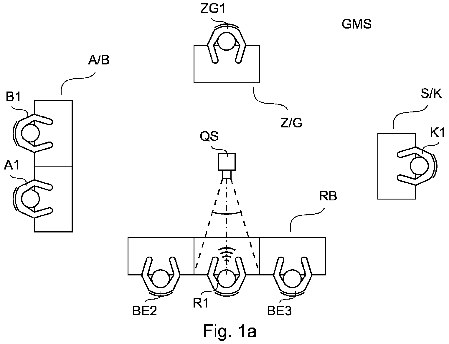
- the courtroom has a judge's bench RB, each with a seat for the presiding judge R1 and two associate judges BE2, BE3, an area Z/G for witnesses or experts ZG1, an area for the litigants, defense A/B with court B1 and his Legal representative A1 and lawsuit S/K with plaintiff K1.
- the courtroom media system GMS also has a controllable camera QS, which in this exemplary embodiment is arranged essentially centrally in the courtroom.
- the controllable camera QS is controlled by means of an acoustic signal.
- a signal is first received.
- the signal is an acoustic signal which is received via a microphone.
- the acoustic signal is advantageously received by a stereo microphone; it is also possible to receive the acoustic signal signals from a plurality of microphones, preferably located at spaced apart locations in the courtroom. Due to the level difference between the individual microphones, it is possible to localize the position of a signal source.
- each of the areas RB, Z/G, A/B, S/K has a microphone as a signal receiver for each person R1, BE2, BE3, ZG1, A1, B1 located in the respective area. This simplifies the localization of the source of the acoustic signal.
- the controllable camera QS is set to a predefined setting in such a way that the controllable camera QS is set to the predefined position of the presiding judge R1 ( 1 a) .
- the setting is predefined in such a way that facial expressions and gestures of the presiding judge R1 are recorded in the camera image of the controllable camera QS, in other words the face and hands of the presiding judge R1 and in particular his upper body are recorded.
- controllable camera QS is aligned with a first predefined setting at the first point in time in such a way that the controllable camera QS captures the presiding judge R1.
- the controllable camera QS is set to a further predefined setting such that the controllable camera QS is centered on the predefined position of the court B1 ( Fig. 1 b) and the position of the court B1 and the court B1 himself is recorded in the camera image of the controllable camera QS.
- the controllable camera QS thus documents, for example, gestural and mimic reactions of the court B1 to the statements of the witness/expert ZG1.
- the signal for controlling the controllable camera QS is the position of the voice of the witness/expert ZG1, which is localized by the microphones of the courtroom media system GMS at a different position than the predefined position to which the controllable camera QS is set , in this embodiment the position of courtroom media system GMS.
- the to this second The predefined position of the predefined setting of the controllable camera QS thus differs from the localized position of the source of the acoustic signal.
- the courtroom media system GMS localizes the voice of the witness/expert ZG1 using a stereo microphone and/or a plurality of microphones.
- the zoom setting of the controllable camera QS is selected in such a way that the image section is the same in both predefined settings.
- the detail of the image shows the full width of the table at which the presiding judge R1 and the court B1 are seated.
- the person R1, B1 located in the focus of the controllable camera QS is therefore shown with the same image section in both predefined settings, ie they appear the same size in the image captured by the controllable camera QS.
- the zoom setting is selected in such a way that the image section is the same in both predefined settings.
- the detail of the image shows the full width of the table at which the presiding judge R1 and the court B1 are seated.
- the person R1, B1 located in the focus of the controllable camera QS is therefore shown with the same image section in both predefined settings, ie they appear the same size in the image captured by the controllable camera QS.
- the zoom setting is not only the panning and tilting of the controllable QS camera are pre
- controllable camera QS is set again to the predefined setting of the presiding judge R1 ( 1 a) .
- the panning angle, tilting angle and zoom setting of the controllable camera QS are preset in such a way that the face, hands and upper body of the presiding judge R1 are captured.
- controllable camera QS has two different predefined settings for controllable parameters (pan angle, tilt angle and zoom setting). It is also possible for a controllable camera QS to have a larger number (more than two) of different predefined settings that can be set using acoustic, visual or electrical signals. With it different areas of the courtroom can be recorded and documented in the camera image of the controllable QS camera.
- FIG 2 A further exemplary embodiment of the courtroom media system GMS according to the invention is shown in FIG 2 .
- the controllable camera QS also has two different predefined settings for controllable parameters, in particular pan angle, tilt angle and zoom setting.
- the controllable camera QS is set to the position of the witness/expert ZG1 ( Fig. 2 a)
- the controllable camera QS is set to the area of defense A/B ( Fig. 2 b) .
- the centrally arranged controllable camera QS is also controlled by means of acoustic signals.
- the first acoustic signal is the voice of the witness/expert ZG1, which is localized by microphones of the courtroom media system GMS.
- the controllable camera QS Upon receipt of this acoustic signal, the controllable camera QS is set to the first predefined setting in such a way that the controllable camera QS captures the witness/expert ZG1 ( Fig. 2 a) and in particular records and documents his gestures and facial expressions.
- conclusions about the credibility of a witness ZG1 are possible.
- Another acoustic signal is the voice of courtroom media system GMS.
- the controllable camera QS Upon receipt of this second acoustic signal, the controllable camera QS is set to the second predefined setting in such a way that the controllable camera QS captures the area of defense A/B ( Fig. 2 b) and simultaneously records gestures and facial expressions of both defense counsel A1 and court B1.
- another acoustic signal is the voice of the defense attorney A1, which is localized by the microphones of the courtroom media system GMS.
- the controllable camera QS is Reception of this further acoustic signal is set to the second predefined setting in such a way that the controllable camera QS also covers the area of defense A/B ( Fig. 2 b) and simultaneously records gestures and facial expressions of both defense counsel A1 and court B1.
- controllable camera QS in turn has two different predefined settings of controllable parameters (pan angle, tilt angle and zoom setting).
- the controllable camera QS is set to the area of the judges' bench RB ( Fig. 3 a)
- the controllable camera QS is set to the area of defense A/B ( Fig. 3 b) .
- the first acoustic signal is generated by the voice of one and/or the voices of several judges R1, BE2, BE3 arranged on the judges' bench.
- Each of the voices of the judges R1, BE2, BE3 arranged at the judge's bench thus generates the first acoustic signal, which is localized by the microphones of the courtroom media system GMS.
- the controllable camera QS is set to the first predefined setting in such a way that the controllable camera QS captures the area of the judges' bench RB ( Fig. 3 a) and records.
- Another acoustic signal is the voice of courtroom media system GMS.
- the controllable camera QS is activated analogously to the previous exemplary embodiment (see Fig. 2 b) set to the second predefined setting such that the controllable camera QS covers the area of defense A/B ( Fig. 3 b) and simultaneously records gestures and facial expressions of both defense counsel A1 and court B1.
- another acoustic signal is the voice of defense counsel A1, which is localized by the microphones of the courtroom media system GMS.
- Each of the voices of the persons A1, B1 arranged in the area for defense A/B therefore generates a second acoustic signal which is localized by the microphones of the courtroom media system GMS.
- the controllable camera QS is set to the second predefined setting in such a way that the controllable camera QS also captures the area of defense A/B ( Fig. 3 b) and simultaneously records gestures and facial expressions of both defense counsel A1 and court B1.
- FIG 4 A further exemplary embodiment of the courtroom media system GMS according to the invention is shown in FIG 4 .
- the courtroom media system GMS has two controllable cameras QS1, QS2.
- the two controllable cameras QS1, QS2 are arranged at different positions in the courtroom and can each be controlled independently of one another.
- the courtroom media system GMS also has two second output devices VZ1, VZ2.
- the first controllable camera QS1 has only one predefined setting for the controllable parameters.
- the first controllable camera QS1 is permanently set to the area of the judges' bench RB, the first controllable camera QS1 therefore permanently records an image of the area of the judges' bench RB and the people R1, BE2, BE3 arranged therein.
- This camera image is output on one and/or both second output devices VZ1, VZ2.
- the first camera can also be designed in a non-controllable manner and be permanently aimed at the accused and/or the witness.
- the second controllable camera QS2 has two different predefined settings: In the first predefined setting, the second controllable camera QS2 is set to the area for witnesses and experts Z/G ( Fig. 4 a) , in the second predefined setting, the second controllable camera QS2 is aligned with the area of defense A/B in such a way that the second controllable camera QS2 is centered on the predefined position of the court B1 ( Fig. 4 b) and the position of the court B1 and the court B1 himself is recorded in the camera image of the second controllable camera QS2.
- the camera image of the second controllable camera QS2 captured in the two different predefined settings is also output on one and/or both second output devices VZ1, VZ2.
- the second controllable camera QS2 is in turn controlled by means of acoustic signals.
- the first acoustic signal is, as in the previous embodiment (s. 3 ), generated by the vote of one and/or the votes of several of the judges R1, BE2, BE3 located at the bench.
- Each of the voices of the judges R1, BE2, BE3 arranged at the judge's bench thus generates the first acoustic signal, which is localized by the microphones of the courtroom media system GMS.
- the second controllable camera QS2 Upon receipt of this first acoustic signal, the second controllable camera QS2 is set to the first predefined setting in such a way that the second controllable camera QS2 captures the area for witnesses and experts Z/G ( Fig. 4 a) and records.
- Another acoustic signal is the voice of courtroom media system GMS.
- the second controllable camera QS2 Upon receipt of this second acoustic signal, the second controllable camera QS2 is set to the second predefined setting in such a way that the second controllable camera QS2 captures the position of the court B1 ( Fig. 4 b) and gestures and facial expressions of the court B1 records.
- FIG figure 5 A further exemplary embodiment of the courtroom media system GMS according to the invention is shown in FIG figure 5 .
- the courtroom media system GMS has two controllable cameras QS1, QS2.
- the two controllable cameras QS1, QS2 are arranged at different positions in the courtroom and can each be controlled independently of one another. While a camera is placed behind the bench RB, the other camera is arranged in front of the bench RB.
- the courtroom media system GMS also has two second output devices VZ1, VZ2.
- the first controllable camera QS1 has various predefined settings for the controllable parameters. In these predefined settings, the first controllable camera QS1 is permanently set to the area of the judges' bench RB, the first controllable camera QS1 therefore permanently records an image of the area of the judges' bench RB and the person R1, BE2, BE3 active therein. This camera image is output on one and/or both second output devices VZ1, VZ2.
- the second controllable camera QS2 has a number of different predefined settings. These include, for example, the witness area, the dock A/B with the court B1 and his lawyer B2, the public prosecutor's office S/K and/or the judge's bench RB.
- the second controllable camera QS2 is set to the area for witnesses and experts Z/G ( Fig. 5a )
- the second controllable camera QS2 is aimed at the area of defense A/B such that the second controllable camera QS2 is centered on the predefined position of the court B1 ( Fig.
- the camera image of the second controllable camera QS2 captured in the two different predefined settings is also output on one and/or both second output devices VZ1, VZ2.
- the second controllable camera QS2 is in turn controlled by means of acoustic signals.
- acoustic signals As in the previous exemplary embodiments (see 3 , 4 ), generated by the vote of one and/or the votes of several of the judges R1, BE2, BE3 located at the bench.
- Each of the voices of the judges R1, BE2, BE3 arranged at the judges' bench thus generates the first acoustic signal, which is emitted by the microphones of the courtroom media system GMS is localized.
- the second controllable camera QS2 Upon receipt of this first acoustic signal, the second controllable camera QS2 is set to the first predefined setting in such a way that the second controllable camera QS2 captures the area for witnesses and experts Z/G ( Fig. 5 a) and records.
- Another acoustic signal is the voice of courtroom media system GMS.
- the second controllable camera QS2 Upon receipt of this second acoustic signal, the second controllable camera QS2 is set to the second predefined setting in such a way that the second controllable camera QS2 captures the position of the court B1 ( Fig. 5 b) and gestures and facial expressions of the court B1 records.
- controllable cameras QS, QS1, QS2 are controlled by means of acoustic signals.
- controllable cameras QS, QS1, QS2 can also be controlled exclusively or additionally by one or a plurality of visual signals, for example by hand movements.
- the visual signal is detected by an optical sensor, for example a camera, in such a way that the visual signal is localized.
- Another option is to input electrical signals into a central control unit SE (see Fig. Figures 6 - 8 ) of the courtroom media system GMS by an operator of the central control unit SE.
- the courtroom media system GMS according to the invention has the matrix circuit MS.
- the matrix circuit MS has a plurality of connections in the form of source interfaces MSE, via which the matrix circuit MS is connected to the sources Q1, Q2, Q3, Q4, Q5, QS.
- Each source interface MSE is connected to exactly one source Q1, Q2, Q3, Q4, Q5, QS.
- each source Q1, Q2, Q3, Q4, Q5, QS has an interface QSA.
- the controllable camera QS is connected to the matrix circuit MS via the output interface QSA to the input interface MSE.
- the input interface QSS of the controllable camera QS is connected to the output interface MSS of the matrix circuit MS.
- the matrix circuit MS also has the output interfaces MSA, to which an output device VE1, VE2, VE3, VZ1, VZ2 is connected in each case.
- the first output device VE1 is an output device that is available to the judges R1, BE2, BE3.
- the first output device VE1 also serves as an output device for the judiciary, but also as a director's monitor on which the image and sound content intended for the second output device VZ1, VZ2 can be displayed.
- the second output device VZ1, VZ2 is, for example, an output device that displays video and audio content intended for the public.
- the second output devices VZ1, VZ2 can be located in a different room than the first output devices VE1, VE2, VE3. All output devices VE1, VE2, VE3, VZ1, VZ2 have components for displaying image content and/or audio content and/or are connected to such.
- Each output device VE1, VE2, VE3, VZ1, VZ2 also has an interface QSA.
- the matrix circuit MS is connected to the central control unit SE via the control input interface MSS.
- the central control unit SE has the control output interface SSA.
- the central control unit SE has the control interface CS, which is connected to the output interface CPS of the control panel CP.
- the Control Panel CP has its own display and control element.
- the configuration for the control logic is stored on the central control unit SE.
- the output devices VE1, VE2, VE3, VZ1, VZ2 and sources Q1, Q2, Q3, Q4, Q5, QS to be controlled can be connected via Ethernet, RS-232, infrared, relays or general I/O ports.
- the control logic is provided via a cloud and can be loaded into a memory in the central control unit SE.
- the configuration control unit KSE which is arranged separately in this exemplary embodiment, is also detachably connected to the central control unit SE.
- the central control unit SE has an interface, as does the configuration control unit KSE.
- the operator of the control panel CP can edit the image and/or sound content received from the controllable camera QS via the operating element of the control panel CP.
- the displayed image and/or sound content can be cut out and/or cropped and/or the volume can be changed via the separate control unit SE.
- data is requested for the installation and/or configuration of the central control unit SE.
- the data are stored in a memory of the separate configuration control unit KSE.
- the data includes the settings relevant to installation and/or configuration for the particular courtroom in which the Courtroom Media System Controller GMS is to be deployed.
- This data is read in by the central control unit SE.
- This is followed by the installation and/or configuration on the central control unit SE.
- a program is executed on the central control unit SE.
- the courtroom has a publicly accessible area for spectators P, a judge's bench RB, each with a seat for the presiding judge R1 and two assessors BE2, BE3, an area Z/G for witnesses/experts ZG1, and one area each for the parties to the lawsuit S/K and Defense A/B, up.
- the central element of the courtroom media system controller GMS is the matrix circuit MS to which all sources Q1, Q2, Q3, Q4, Q5, QW, QS are connected via source interfaces QSA.
- the sources Q1, Q2, Q3, Q4, Q5, QW, QS are mobile terminals (laptops) of the presiding judge Q1, the two assessors Q2, Q3, and one mobile terminal each Q4, Q5 of the two litigants.
- a free connection provides the option that a witness and/or expert witness can join a source QW.
- a controllable camera QS is connected to the matrix circuit MS.
- the output devices VDM, VE2, VE3, VZ1, VZ2 are also connected to the matrix circuit MS via output interfaces MSA.
- the output device VDM is the master output device and outputs video and/or audio content to the presiding judge R1.
- the first output devices VE2, VE3 are set up to output video and/or audio content to the assessors.
- the second output devices VZ1, VZ2 are publicly accessible output devices, in this exemplary embodiment large screens or screens.
- the matrix circuit MS is located in the courtroom itself in this embodiment, but it is also possible to locate the matrix circuit MS in a remote location, e.g., the IT and server room of the courthouse.
- the configuration control unit KSE which is arranged separately, is also detachably connected to the central control unit SE.
- the courtroom media system GMS is controlled via a control panel CP.
- the presiding judge R1 can use the control panel CP to control the entire technology of the courtroom media system GMS in the courtroom. However, it is also possible to transfer this control to another person via the control panel CP, so that the presiding judge R1 is not additionally burdened with it.
- the operator of the CP control panel uses the operating element of the CP control panel to select one of the sources Q1, Q2, Q3, Q4, Q5, QW, QS for receiving the video and/or audio content. This selection is sent from the control panel CP to the central control unit SE.
- the received picture and/or sound content is not shown on the display of the control panel CP itself, but first on the master output device VDM, which performs a preview function.
- the presiding judge R1 can check the received image and/or audio content.
- the presiding judge R1 use the master output device VDM to change and edit the image and/or sound content selected and displayed on the master output device VDM, eg cut out, crop or change the volume.
- the presiding judge R1 can also process the image and/or sound content received from the controllable camera QS in the same way using the control panel CP.
- the presiding judge R1 or the operator of the control panel CP uses the control panel CP to select one or a plurality of the output devices VDM, VE2, VE3, VE4, VZ1, VZ2 for outputting the source Q1, Q2, Q3 selected by the source , Q4, Q5, QW, QS received picture and/or sound content.
- the received image and/or audio content is then displayed on the selected output device(s) VDM, VE2, VE3, VE4, VZ1, VZ2.
Landscapes
- Engineering & Computer Science (AREA)
- Multimedia (AREA)
- Signal Processing (AREA)
- Studio Devices (AREA)
Abstract
Die Erfindung betrifft ein Verfahren zur Steuerung einer steuerbaren Kamera, mit dem die steuerbare Kamera in der Höhe bzw. Tiefe und seitlich schwenkbar ist und deren Zoom steuerbar ist, sowie ein Gerichtssaal-Mediensystem mit einem Signalempfänger, einer steuerbaren Kamera einer Steuereinheit und einem Speicher, dadurch gekennzeichnet, dass über den Signalempfänger ein Signal empfangbar und die Position des Signals lokalisierbar ist, wobei auf der Steuerung ein Softwareprogramm ausführbar ist, durch das die steuerbare Kamera in eine im Speicher abgelegte vordefinierte Einstellung einstellbar ist.
Description
Die Erfindung betrifft ein Verfahren zur Steuerung einer steuerbaren Kamera, mit dem die steuerbare Kamera in der Höhe bzw. Tiefe und seitlich schwenkbar ist und deren Zoom steuerbar ist, sowie ein Gerichtssaal-Mediensystem mit einem Signalempfänger, einer steuerbaren Kamera einer Steuereinheit und einem Speicher, dadurch gekennzeichnet, dass über den Signalempfänger ein Signal empfangbar und die Position des Signals lokalisierbar ist, wobei auf der Steuerung ein Softwareprogramm ausführbar ist, durch das die steuerbare Kamera in eine im Speicher abgelegte vordefinierte Einstellung einstellbar ist.The invention relates to a method for controlling a controllable camera, with which the controllable camera can be swiveled in height or depth and laterally and whose zoom can be controlled, as well as a courtroom media system with a signal receiver, a controllable camera, a control unit and a memory, characterized in that a signal can be received via the signal receiver and the position of the signal can be localized, a software program being executable on the controller, by means of which the controllable camera can be set to a predefined setting stored in the memory.
Steuerbare Kameras sind aus dem Stand der Technik bekannt. Steuerbare PTZ-Kameras können sich nach oben und unten sowie seitlich bewegen. Diese Funktion wird als PTZ bezeichnet, wobei das "P" für engl. pan ,schwenken' und das "T" für tilt ,neigen' steht. Das "Z" kennzeichnet eine Zoomfunktion. Steuerbare Kameras können feste oder sich bewegende Objekte erfassen und zur besseren Identifizierung Bildausschnitte vergrößern. Kombiniert werden diese PTZ-Kameras mit zusätzlichen Funktionen, wie z.B. dem Autotracking. Damit wird eine Person erfasst und verfolgt. PTZ-Kameras werden z.B. zur Live-Überwachung eingesetzt. Straftaten können z.B. in Flughäfen oder in Stadien so schnell erkannt werden, dass das Wachpersonal zeitnah einschreiten kann. Aus der PTZ-Funktion ergeben sich Vor- und Nachteile: Durch ihre Schwenk- und Neigetechnik können sie einen großen Bereich abtasten. Andererseits ist der Bereich, den sie nicht einsehen, ungeschützt. Das Tracking wird über Bewegung von Objekten bzw. Menschen und/oder audiobasiert durchgeführt. Bei fortschrittlichen Videokonferenzsystemen mit PTZ-Kameras wird hierbei die PTZ-Kamera auf den gegenwärtig sprechenden Teilnehmer geschwenkt und auf sein Gesicht gezoomt.Controllable cameras are known from the prior art. Controllable PTZ cameras can move up and down and sideways. This function is called PTZ, where the "P" stands for English. pan and the "T" stands for tilt. The "Z" denotes a zoom function. Controllable cameras can capture fixed or moving objects and enlarge image sections for better identification. These PTZ cameras are combined with additional functions such as auto tracking. This is used to capture and track a person. PTZ cameras are used, for example, for live surveillance. Criminal offenses, for example in airports or stadiums, can be detected so quickly that the security personnel can intervene promptly. The PTZ function has advantages and disadvantages: Thanks to their panning and tilting technology, they can scan a large area. On the other hand, the area they cannot see is unprotected. The tracking is carried out via the movement of objects or people and/or based on audio. In advanced video conferencing systems with PTZ cameras the PTZ camera is panned to the currently speaking participant and zooms in on their face.
Nachteil an den gegenwärtigen Lösungen ist, dass wichtige Ereignisse abseits vom gegenwärtigen Sprechenden nicht erfasst werden. So ist es insbesondere während Gerichtsverhandlungen neben den Wortmeldungen der Verfahrensbeteiligten ebenso relevant, Reaktionen von anderen Verfahrensbeteiligten als dem gegenwärtig erfassten Sprechenden zu erfassen, wie z.B. von Zeugen und/oder Beklagten.The disadvantage of the current solutions is that important events apart from the current speaker are not recorded. In addition to the requests to speak by the parties to the proceedings, it is also relevant, especially during court hearings, to record reactions from parties to the proceedings other than the currently recorded speaker, such as witnesses and/or defendants.
Daher liegt der Erfindung die Aufgabe zugrunde, ein Verfahren zur Steuerung einer Kamera eines Gerichtssaal-Mediensystems bereitzustellen, die die Nachteile des Standes der Technik überwindet. Es ist ebenfalls Aufgabe der Erfindung, ein Gerichtssaal-Mediensystem bereitzustellen, mit dem eine steuerbare Kamera steuerbar ist.It is therefore an object of the invention to provide a method for controlling a camera of a courtroom media system which overcomes the disadvantages of the prior art. It is also an object of the invention to provide a courtroom media system capable of controlling a controllable camera.
Die Aufgabe wird mittels des Verfahrens zur Steuerung einer steuerbaren Kamera gemäß Anspruch 1 gelöst. Vorteilhafte Ausführungen der Erfindung sind in den Unteransprüchen dargelegt.The object is achieved by means of the method for controlling a controllable camera according to claim 1. Advantageous embodiments of the invention are set out in the dependent claims.
Das erfindungsgemäße Verfahren zur Steuerung einer steuerbaren Kamera weist drei Verfahrensschritte auf: Im ersten Verfahrensschritt wird ein Signal empfangen. Im zweiten Verfahrensschritt wird die Position der Quelle des Signals lokalisiert. Im dritten Verfahrensschritt wird eine vordefinierte Einstellung eines der steuerbaren Parameter der steuerbaren Kamera eingestellt. Diese vordefinierte Einstellung der steuerbaren Kamera wie beispielsweise die Position der steuerbaren Kamera, also die Schwenkposition und/oder die Neigungsposition, kann beispielsweise die gesamte Bank der Zeugen, Gutachter, Staatsanwaltschaft und/oder der Angeklagten bzw. Beklagten sein. Die Einstellung der vordefinierten Einstellung kann in Abhängigkeit von der Position der Quelle des Signals erfolgen.The method according to the invention for controlling a controllable camera has three method steps: In the first method step, a signal is received. In the second step, the position of the source of the signal is localized. In the third method step, a predefined setting of one of the controllable parameters of the controllable camera is set. This predefined setting of the controllable camera, such as the position of the controllable camera, ie the pan position and/or the tilt position, can be, for example, the entire bank of witnesses, experts, public prosecutors and/or the accused or defendants. The setting of the predefined setting can be done depending on the position of the source of the signal.
Das Verfahren zur Steuerung einer steuerbaren Kamera eines Gerichtssaal-Mediensystems mit vordefinierter Einstellung ermöglicht in einer vorteilhaften Ausführung das Minimieren von Fehlfunktionen, bspw. aufgrund inkorrekter Lokalisation des Audiosignals und damit verbunden die Sicherstellung der Chancengleichheit für alle Teilnehmer der Verhandlung. Im Einzelnen wird somit die sichere und fehlerfreie Gewähr des im Grundgesetz verankerten, rechtlichen Gehörs, einer Pflicht, die besonders Gerichte erfüllen müssen, gewährt. Da für die Wahrnehmung desrechtlichen Gehör dies Aussagen der streitenden Parteien nicht bloß gehört, sondern inhaltlich gewürdigt werden müssen, ist eine korrekte, vollständige und zwischen den Parteien gleichartige Wiedergabe durch das Gerichtssaal-Mediensystems im Sinne der Erfindung.In an advantageous embodiment, the method for controlling a controllable camera of a courtroom media system with a predefined setting makes it possible to minimize malfunctions, for example due to incorrect localization of the audio signal, and thus to ensure equal opportunities for all participants in the hearing. In detail, the secure and error-free guarantee of the right to be heard as anchored in the Basic Law, a duty that courts in particular have to fulfill, is granted. Since the statements of the disputing parties must not only be heard for the perception of the right to be heard, but must also be appreciated in terms of content, correct, complete and similar reproduction between the parties by the courtroom media system is within the meaning of the invention.
In einer Weiterbildung der Erfindung wird ein akustisches und/oder ein visuelles und/oder ein elektrisches Signal empfangen. Das akustische Signal ist vorzugsweise die menschliche Stimme, wobei die Quelle eine Person ist, deren Position lokalisiert wird. Das akustische Signal kann optional mittels Spracherkennung derart analysiert werden, dass eine Spracherkennung erfolgt, die Steuerung der steuerbaren Kamera also mittels Sprachbefehlen möglich ist. Alternativ oder zusätzlich wird ein visuelles Signal empfangen. Das visuelle Signal kann z.B. eine Handbewegung sein, wobei die Quelle eine oder mehrere Personen ist. Ebenfalls alternativ oder zusätzlich wird ein elektrisches Signal empfangen, das mittels einer elektrischen Eingabevorrichtung erzeugt wird.In a development of the invention, an acoustic and/or a visual and/or an electrical signal is received. The acoustic signal is preferably human voice, with the source being a person whose position is being located. The acoustic signal can optionally be analyzed using voice recognition in such a way that voice recognition takes place, ie the controllable camera can be controlled using voice commands. Alternatively or additionally, a visual signal is received. For example, the visual signal may be a hand gesture, with the source being one or more people. Also alternatively or additionally, an electrical signal is received, which is generated by means of an electrical input device.
In einer weiteren Ausführung der Erfindung wird das akustische Signal über ein Stereo-Mikrophon empfangen. Ein Stereo-Mikrophon weist zwei Mikrophone in einer Einhausung auf. Mittels Schalldruck-Pegeldifferenz und/oder Laufzeitdifferenz des akustischen Signals wird die Quelle des akustischen Signals lokalisiert.In a further embodiment of the invention, the acoustic signal is received via a stereo microphone. A stereo microphone has two microphones in one housing. The source of the acoustic signal is localized by means of the sound pressure level difference and/or transit time difference of the acoustic signal.
In einer weiteren Gestaltung der Erfindung wird die Quelle des akustischen Signals über zwei Mikrophone lokalisiert. Zwei oder eine Mehrzahl von Mikrofonen sind in einem Mikrofonsystem zusammengefasst. Über erzeugte Schalldruck-Pegeldifferenzen und/oder Laufzeitdifferenzen wird die Quelle des akustischen Signals lokalisiert.In a further embodiment of the invention, the source of the acoustic signal is localized via two microphones. Two or a plurality of microphones are combined in a microphone system. The source of the acoustic signal is localized via generated sound pressure level differences and/or transit time differences.
In einer vorteilhaften Ausbildung der Erfindung wird das visuelle Signal über eine Kamera und/oder einen Fotodetektor empfangen. Im einfachsten Fall wird mittels eines lichtempfindlichen Fotodetektors ein Helligkeitsunterschied insbesondere im Spektralbereich des sichtbaren Lichts detektiert. Der Helligkeitsunterschied kann z.B. durch eine Handbewegung verursacht werden. Die Kamera zum Empfang des visuellen Signals ist bevorzugt unterschiedlich zu der steuerbaren Kamera und bevorzugt an einer unterschiedlichen Position zur steuerbaren Kamera angeordnet, um ein visuelles Signal von an einer Mehrzahl an unterschiedlichen Positionen angeordneten Quellen zu empfangen.In an advantageous embodiment of the invention, the visual signal is received via a camera and/or a photodetector. In the simplest case, a light-sensitive photodetector is used to detect a difference in brightness, particularly in the spectral range of visible light. The difference in brightness can be caused by a hand movement, for example. The camera for receiving the visual signal is preferably different from the steerable camera and preferably located at a different location from the steerable camera to receive a visual signal from sources located at a plurality of different locations.
In einer Weiterbildung der Erfindung wird die Quelle des visuellen Signals aus den von der Kamera und/oder dem Fotodetektor empfangenen Signal lokalisiert. Die Kamera und/oder der Fotodetektor ist vorzugsweise an einer Position angeordnet, in der alle am Prozess beteiligten Personen mittels der Kamera und/oder des Fotodetektors erfasst werden. Möglich ist auch die Verwendung einer Mehrzahl von Kameras und/oder Fotodetektoren, die einen oder mehrere Bereiche des Gerichtssaales erfasst. Insbesondere kann die Kamera und/oder der Fotodetektor in einem Endgerät (z.B. Laptop, Smartphone) angeordnet sein, das einer Prozesspartei zur Verfügung steht. Das visuelle Signal wird dann von einer Mehrzahl oder allen Prozessparteien empfangen und lokalisiert werden.In a development of the invention, the source of the visual signal is localized from the signal received from the camera and/or the photodetector. The camera and/or the photodetector is preferably arranged in a position in which all persons involved in the process are recorded by means of the camera and/or the photodetector. It is also possible to use a plurality of cameras and/or photodetectors which cover one or more areas of the courtroom. In particular, the camera and/or the photodetector can be arranged in a terminal device (e.g. laptop, smartphone) that is available to a litigant. The visual signal will then be received and located by a majority or all of the process parties.
In einer weiteren Ausgestaltung der Erfindung wird das elektrische Signal über ein Eingabegerät empfangen. Das Eingabegerät ist bevorzugt ein Endgerät, z.B. ein Laptop, Smartphone, Tablet, mittels dem eine oder eine Mehrzahl von Prozessparteien ein elektrisches Signal erzeugen kann.In a further embodiment of the invention, the electrical signal is received via an input device. The input device is preferably an end device, e.g. a laptop, smartphone, tablet, which can be used by one or more process participants to generate an electrical signal.
In einer Weiterbildung der Erfindung wird das elektrische Signal über die Position eines Eingabegerätes lokalisiert. Das Eingabegerät ist bevorzugt ein Endgerät, z.B. ein Laptop, Smartphone, Tablet, wobei eine Mehrzahl von Prozessbeteiligten über jeweils ein Endgerät verfügt. Die Lokalisierung des Signals erfolgt durch Ermittlung der Position des Endgerätes.In a development of the invention, the electrical signal is localized via the position of an input device. The input device is preferably a terminal, for example a laptop, smartphone, tablet, with a plurality of process participants each having a terminal at their disposal. The signal is localized by determining the position of the end device.
In einer weiteren Ausführung der Erfindung umfasst die vordefinierte Einstellung eine Zoom-Einstellung. Mittels der Zoom-Einstellung kann der Bildausschnitt des Kamerabildes z.B. derart eingestellt werden, dass unterschiedliche Bereiche des Gerichtssaales im Kamerabild gleich groß dargestellt werden.In another embodiment of the invention, the predefined setting includes a zoom setting. Using the zoom setting, the image section of the camera image can be adjusted, for example, in such a way that different areas of the courtroom are displayed in the same size in the camera image.
In einer weiteren Ausbildung der Erfindung wird die Zoom-Einstellung derart gewählt, dass mehrere Personen im Kamerabild erfasst werden. In einer optionalen Ausführungsform wird die Zoom-Einstellung derart gewählt, dass mehrere Personen einer Prozesspartei im Kamerabild erfasst werden. Damit wird gewährleistet, dass auch der Ausschnitt des Kamerabildes groß genug bleibt, um alle Verfahrensbeteiligten einer Prozesspartei im Bild festzuhalten.In a further embodiment of the invention, the zoom setting is selected in such a way that several people are captured in the camera image. In an optional embodiment, the zoom setting is selected in such a way that several people from one process party are captured in the camera image. This ensures that the section of the camera image remains large enough to capture all those involved in the process of a litigant in the image.
In einer Weiterbildung der Erfindung wird die im Erfassungsbereich der Kamera befindliche Person ermittelt. Die Zoom-Einstellung wird derart gewählt, dass das Kamerabild auf die im Erfassungsbereich der Kamera ermittelten Personen im Kamerabild gezoomt wird. Die Ermittlung erfolgt über die Position der im Erfassungsbereich der Kamera befindliche Person. Der Zoom wird so eingestellt, dass insbesondere Gestik und Mimik der Person erfasst und aufgezeichnet werden kann.In a development of the invention, the person located in the detection range of the camera is determined. The zoom setting is selected in such a way that the camera image is zoomed to the people in the camera image that have been determined in the detection area of the camera. The determination is based on the position of the person in the detection range of the camera. The zoom is set in such a way that the person's gestures and facial expressions in particular can be captured and recorded.
In einer weiteren Ausgestaltung der Erfindung umfasst die vordefinierte Einstellung eine vordefinierte Position, auf die das Kamerabild zentriert wird. Eine vordefinierte Position umfasst z.B. einen Schwenk- und Neigungswinkel sowie den Zoom der steuerbaren Kamera. Damit wird gewährleistet, dass auch der Ausschnitt des Kamerabildes groß genug bleibt, um alle Verfahrensbeteiligten einer Prozesspartei im Bild der steuerbaren Kamera zu erfassen.In a further embodiment of the invention, the predefined setting includes a predefined position on which the camera image is centered. A predefined position includes e.g. a pan and tilt angle as well as the zoom of the controllable camera. This ensures that the section of the camera image remains large enough to capture all those involved in the process of a process party in the image of the controllable camera.
In einer weiteren Gestaltung der Erfindung ist die vordefinierte Position eine andere Position als die lokalisierte Quelle des empfangenen Signals. Dies ist beispielsweise dann vorteilhaft, wenn die Reaktion eines Angeklagten auf die Aussage eines Zeugen oder die Reaktion eines Zeugen auf eine Frage des Richters, Klägers oder des Beklagten erfasst werden soll.In a further embodiment of the invention, the predefined position is a different position than the localized source of the received signal. This is advantageous, for example, when a suspect's response to testimony from a witness or a witness's response to a question from the judge, plaintiff, or defendant is to be recorded.
In einer vorteilhaften Weiterbildung umfasst das von der Kamera in der vordefinierten Position erfasste Bild die lokalisierte Position der Quelle des empfangenen Signals. Diese vordefinierte Voreinstellung der Kamera wie beispielsweise die Position der Kamera, also die Schwenkposition und/oder die Neigungsposition, kann beispielsweise die gesamte Bank der Kläger bzw. Staatsanwaltschaft und/oder der Angeklagten bzw. Beklagten sein.In an advantageous development, the image captured by the camera in the predefined position includes the localized position of the source of the received signal. This predefined presetting of the camera, such as the position of the camera, ie the pan position and/or the tilt position, can be, for example, the entire bank of the plaintiff or the public prosecutor's office and/or the accused or the defendant.
In einer weiteren Ausführung der Erfindung wird eine vordefinierte Einstellung eines der steuerbaren Parameter der steuerbaren Kamera eingerichtet. Die steuerbaren Parameter der steuerbaren Kamera umfassen z.B. den Schwenk- und Neigungswinkel sowie den Zoom der steuerbaren Kamera. Die steuerbare Kamera wird mittels Einstellung eines oder mehrerer der steuerbaren Parameter derart ausgerichtet, dass beispielsweise die gesamte Bank der Kläger bzw. Staatsanwaltschaft und/oder der Angeklagten bzw. Beklagten erfasst wird.In a further embodiment of the invention, a predefined setting of one of the controllable parameters of the controllable camera is established. The controllable parameters of the controllable camera include, for example, the pan, tilt and zoom of the controllable camera. The controllable camera is aligned by setting one or more of the controllable parameters in such a way that, for example, the entire bank of plaintiffs or the public prosecutor's office and/or the accused or defendants is recorded.
In einer Weiterbildung der Erfindung werden mehrere vordefinierte Einstellungen der steuerbaren Parameter der steuerbaren Kamera eingerichtet. Die steuerbaren Parameter der steuerbaren Kamera umfassen z.B. den Schwenk- und Neigungswinkel sowie den Zoom der steuerbaren Kamera. Die steuerbare Kamera wird mittels Einstellung mehrerer der steuerbaren Parameter derart ausgerichtet, dass beispielsweise die gesamte Bank der Kläger bzw. Staatsanwaltschaft und/oder der Angeklagten bzw. Beklagten erfasst wird.In a development of the invention, a number of predefined settings for the controllable parameters of the controllable camera are set up. The controllable parameters of the controllable camera include, for example, the pan, tilt and zoom of the controllable camera. The controllable camera is aligned by setting several of the controllable parameters in such a way that, for example, the entire bank of the plaintiff or public prosecutor's office and/or the accused or defendant is recorded.
In einem weiteren Aspekt der Erfindung umfassen die vordefinierten Einstellungen mehrere unterschiedliche Positionen. Dies beinhaltet beispielsweise die Schwenkung, die Neigung und/oder den Zoom.In another aspect of the invention, the predefined settings include a number of different positions. This includes, for example, panning, tilting and/or zooming.
In einer weitere erfindungsgemäßen Gestaltungsform wird die steuerbare Kamera durch ein Control-Panel gesteuert. Das Control-Panel ist hierbei im Gerichtssaal selbst angeordnet. Hierdurch wird gewährleistet, dass die volle Kontrolle des Gerichtssaal-Mediensystems beim Vorsitzenden Richter oder einer von ihm bevollmächtigten Person liegt.In a further embodiment according to the invention, the controllable camera is controlled by a control panel. The control panel is located in the courtroom itself. This ensures that the presiding judge or a person authorized by him has full control of the courtroom media system.
Die Aufgabe wird weiterhin mittels des Gerichtssaal-Mediensystem mit einem Signalempfänger, einer steuerbaren Kamera, einer Steuereinheit und einem Speicher gelöst. Vorteilhafte Ausführungen der Erfindung sind ebenfalls in den Unteransprüchen dargelegt. Außerdem können Positionen von lokalisierten Signalen niemals angefahren werden. Dies kann zu Beispiel der Fall sein, wenn lediglich eine Audiomitschnitt über einen Lautsprecher im Gerichtssaal eingespielt wirdThe object is further solved by means of the courtroom media system with a signal receiver, a controllable camera, a control unit and a memory. Advantageous embodiments of the invention are also set out in the dependent claims. In addition, positions of localized signals can never be approached. This can be the case, for example, if only an audio recording is played over a loudspeaker in the courtroom
Das erfindungsgemäße Gerichtssaal-Mediensystem weist einen Signalempfänger, eine steuerbare Kamera, eine Steuereinheit und einen Speicher auf. Erfindungsgemäß ist über den Signalempfänger ein Signal empfangbar und die Position des Signals lokalisierbar. Auf der Steuereinheit ist ein Softwareprogramm ausführbar, durch das die steuerbare Kamera in eine im Speicher abgelegte vordefinierte Einstellung einstellbar ist. Der Speicher weist die Daten zur Installation und/oder Konfiguration auf. Gleichzeitig können auf der Steuereinheit Daten zur Installation und/oder Konfiguration gespeichert sein, mit denen eine Mehrzahl von unterschiedlichen vordefinierten Einstellungen der steuerbaren Kamera einstellbar ist.The courtroom media system according to the invention has a signal receiver, a controllable camera, a control unit and a memory. According to the invention, a signal can be received via the signal receiver and the position of the signal can be localized. A software program can be executed on the control unit, by means of which the controllable camera can be set to a predefined setting stored in the memory. The memory contains the data for installation and/or configuration. At the same time, data for installation and/or configuration can be stored on the control unit, with which a number of different predefined settings of the controllable camera can be set.
In einer Weiterbildung der Erfindung ist der Signalempfänger geeignet, ein akustisches, ein elektrisches und/oder ein visuelles Signal zu empfangen. Weiterhin ist das Gerichtssaal-Mediensystem dafür geeignet, das empfangene Signal zu lokalisieren. Das akustische Signal ist vorzugsweise die menschliche Stimme, wobei die Quelle eine Person ist, deren Position lokalisiert wird. Das akustische Signal kann optional mittels Spracherkennung derart analysiert werden, dass eine Spracherkennung erfolgt, die Steuerung der steuerbaren Kamera also mittels Sprachbefehlen möglich ist. Alternativ oder zusätzlich wird ein visuelles Signal empfangen. Das visuelle Signal kann z.B. eine Handbewegung sein, wobei die Quelle eine oder mehrere Personen ist. Ebenfalls alternativ oder zusätzlich wird ein elektrisches Signal empfangen, das mittels einer elektrischen Eingabevorrichtung erzeugt wird.In a development of the invention, the signal receiver is suitable for receiving an acoustic, an electrical and/or a visual signal. Furthermore, the courtroom media system is capable of locating the received signal. The acoustic signal is preferably human voice, with the source being a person whose position is being located. The acoustic signal can optionally be analyzed using voice recognition in such a way that voice recognition takes place, ie the controllable camera can be controlled using voice commands. Alternatively or additionally receive a visual signal. The visual signal can be, for example, a hand movement, with the source being one or more people. Also alternatively or additionally, an electrical signal is received, which is generated by means of an electrical input device.
In einer weiteren Ausführung der Erfindung ist der Signalempfänger ein Mikrophon, ein Eingabegerät, ein Fotodetektor und/oder eine Kamera. Zwei oder eine Mehrzahl von Mikrophonen sind in einem Mikrophonsystem zusammengefasst. Über erzeugte Pegeldifferenz und/oder Laufzeitdifferenz wird die Quelle des akustischen Signals lokalisiert. Mittels eines lichtempfindlichen Fotodetektors wird ein Helligkeitsunterschied insbesondere im Spektralbereich des sichtbaren Lichts detektiert. Der Helligkeitsunterschied kann z.B. durch eine Handbewegung verursacht werden. Die Kamera zum Empfang des visuellen Signals ist bevorzugt unterschiedlich zu der steuerbaren Kamera und bevorzugt an einer unterschiedlichen Position zur steuerbaren Kamera angeordnet, um ein visuelles Signal von an einer Mehrzahl an unterschiedlichen Positionen angeordneten Quellen zu empfangen.In a further embodiment of the invention, the signal receiver is a microphone, an input device, a photodetector and/or a camera. Two or a plurality of microphones are combined in a microphone system. The source of the acoustic signal is localized via the generated level difference and/or transit time difference. A light-sensitive photodetector is used to detect a difference in brightness, particularly in the spectral range of visible light. The difference in brightness can be caused by a hand movement, for example. The camera for receiving the visual signal is preferably different from the steerable camera and preferably located at a different location from the steerable camera to receive a visual signal from sources located at a plurality of different locations.
In einer weiteren Gestaltung der Erfindung ist an die zentrale Steuereinheit ein Control-Panel angeschlossen. Das Control-Panel ist dafür vorgesehen und dafür geeignet, die Ausgabe von Inhalten auf den Ausgabeeinrichtungen zu steuern. Das Control-Panel ist die zentrale Kontroll- bzw. Steuerungskomponente für die Steuerung der erfindungsgemäßen Gerichtssaal-Mediensystemsteuerung. Es wird von dem Vorsitzenden oder einer dafür bestimmten Person bedient. Das Control-Panel wird am Platz des Vorsitzenden angeordnet, kann aber an den Arbeitsplatz einer beauftragten Person weitergeleitet werdenIn a further embodiment of the invention, a control panel is connected to the central control unit. The control panel is intended and suitable for controlling the output of content on the output devices. The control panel is the central control component for controlling the inventive courtroom media system control. It is served by the chairman or a person designated for that purpose. The control panel is placed at the chairperson's seat, but can be routed to a designated person's desk
Das Gerichtssaal-Mediensystem kann so optional als geschlossenes System betrieben werden, sodass während einer Gerichtsverhandlung kein Zugriff von Extern beispielsweise durch Dritte möglich ist. Der Richter hat somit die volle Kontrolle über alle Geschehnisse des Gerichtssaalmediensystems. In einer optionalen Ausgestaltung der Erfindung sind alle Elemente zur Steuerung des Gerichtssaal-Mediensystems im Gerichtssaal angeordnet. In einer weiteren optionalen Ausführungsform ist die Steuerung des Gerichtssaalmediensystems während einer Gerichtsverhandlung auf im Gerichtssaal befindliche Steuerungselemente, wie beispielsweise das Control-Panel, begrenzt.The courtroom media system can thus optionally be operated as a closed system, so that no external access, for example by third parties, is possible during a court hearing. The judge thus has full control over everything happening in the courtroom media system. In an optional embodiment of the invention, all elements for controlling the courtroom media system are arranged in the courtroom. In In another optional embodiment, control of the courtroom media system during a court hearing is limited to in-courtroom controls, such as the control panel.
Gerichtssaal-Mediensysteme unterliegen hierbei besonderen Anforderungen. Zum einem muss gewährleistet sein, dass Gerichtssaal-Mediensysteme nicht von außen durch Dritte korrumpiert werden können. Hierfür ist es in einer optionalen Ausgestaltung der Erfindung vorgesehen, dass das Gerichtssaal-Mediensystem als geschlossenes System betrieben wird. In einer besonders bevorzugten Ausführungsform wird das Gerichtssaal-Mediensystem während eines Gerichtsverfahrens als geschlossenes System betrieben. Zum anderen muss das Gerichtssaal-Mediensystem darauf ausgelegt ein, dass den Verfahrensbeteiligten ihr beispielsweise im deutschen Grundgesetz verankertes Recht auf rechtliches Gehör gewährleistet werden kann - allerdings nur insoweit, wie dies der Vorsitzende Richter zulässt, damit beispielsweise die Gerichtsverhandlung selbst nicht als Podium missbraucht werden kann. Andernfalls könnte dem Gericht selbst Verfahrensfehler angelastet werden, oder nicht genehmigte Inhalte eingebracht und dargestellt werden.Courtroom media systems are subject to special requirements. On the one hand, it must be ensured that courtroom media systems cannot be corrupted by third parties from outside. For this purpose, an optional embodiment of the invention provides for the courtroom media system to be operated as a closed system. In a particularly preferred embodiment, the courtroom media system operates as a closed system during a court proceeding. On the other hand, the courtroom media system must be designed so that those involved in the proceedings can be guaranteed their right to a fair hearing, which is enshrined in the German Basic Law, for example - but only to the extent that the presiding judge allows, so that the court hearing itself cannot be misused as a podium, for example . Otherwise, the court itself could be accused of procedural errors, or unauthorized content could be introduced and presented.
Ausführungsbeispiele des erfindungsgemäßen Gerichtssaal-Mediensystems und des erfindungsgemäßen Verfahrens zur Steuerung einer steuerbaren Kamera sind in den Zeichnungen schematisch vereinfacht dargestellt und werden in der nachfolgenden Beschreibung näher erläutert.Exemplary embodiments of the courtroom media system according to the invention and the method according to the invention for controlling a controllable camera are shown in the drawings in a schematically simplified manner and are explained in more detail in the following description.
Es zeigen:
- Fig. 1 a:
- Gerichtssaal-Mediensystem mit steuerbarer Kamera ausgerichtet auf Sprecher
- Fig. 1 b:
- Gerichtssaal-Mediensystem mit steuerbarer Kamera ausgerichtet auf den nicht sprechenden Beklagten
- Fig. 2 a:
- Gerichtssaal-Mediensystem mit steuerbarer Kamera ausgerichtet auf den aussagenden Zeugen
- Fig. 2 b:
- Gerichtssaal-Mediensystem mit steuerbarer Kamera ausgerichtet auf einen Punkt neben dem Sprecher
- Fig. 3 a:
- Gerichtssaal-Mediensystem mit steuerbare Kamera, die alle Personen der Richterbank erfasst
- Fig. 3 b:
- Gerichtssaal-Mediensystem mit steuerbarer Kamera, die Personen des Bereichs der Verteidigung erfasst
- Fig. 4 a:
- Gerichtssaal-Mediensystems mit einer steuerbarer und einer nichtsteuerbaren Kamera, erste Ansicht
- Fig. 4 b:
- Gerichtssaal- Mediensystems mit einer steuerbarer und einer nichtsteuerbaren Kamera, zweite Ansicht
- Fig. 5 a:
- Gerichtssaal-Mediensystems mit zwei steuerbaren Kameras, erste Ansicht
- Fig. 5 b:
- Gerichtssaal- Mediensystems mit zwei steuerbaren Kameras, zweite Ansicht
- Fig. 6:
- Schaltplan der Hardware des Gerichtssaal-Mediensystems
- Fig. 7:
- Alternaive Verschaltung der Hardware eines Gerichtssaal-Mediensystems
- Fig. 8:
- Quellen und Ausgabeeinrichtungen eines Gerichtssaal-Mediensystems
- Fig. 1a:
- Courtroom media system with controllable camera aimed at speakers
- Fig. 1b:
- Courtroom media system with controllable camera aimed at the non-speaking defendant
- Fig. 2a:
- Courtroom media system with controllable camera aimed at the testifying witness
- Fig. 2b:
- Courtroom media system with controllable camera aimed at a point next to the speaker
- Fig. 3a:
- Courtroom media system with controllable camera that captures everyone on the bench
- Fig. 3b:
- Courtroom media system with controllable camera capturing persons in the defense area
- Fig. 4a:
- Courtroom media system with one steerable and one non-steerable camera, first view
- Fig. 4b:
- Courtroom media system with one steerable and one non-steerable camera, second view
- Fig. 5a:
- Courtroom media system with two controllable cameras, first view
- Figure 5b:
- Courtroom media system with two controllable cameras, second view
- Figure 6:
- Schematic of the courtroom media system hardware
- Figure 7:
- Alternative wiring of the hardware of a courtroom media system
- Figure 8:
- Sources and outputs of a courtroom media system
Die Steuerung der steuerbaren Kamera QS erfolgt in diesem Ausführungsbeispiel mittels eines akustischen Signals. Zur Steuerung der steuerbaren Kamera QS wird zunächst ein Signal empfangen. Das Signal ist in diesem Ausführungsbeispiel ein akustisches Signal, das über ein Mikrophon empfangen wird. Das akustische Signal wird vorteilhafterweise von einem Stereo-Mikrophon empfangen, möglich ist auch der Empfang des akustischen Signals von einer Mehrzahl von Mikrophonen, die vorzugsweise an voneinander entfernten Positionen im Gerichtssaal angeordnet sind. Aufgrund der Pegeldifferenz der einzelnen Mikrophone ist eine Lokalisierung der Position einer Signalquelle möglich. Im einfachsten Fall weist jeder der Bereiche RB, Z/G, A/B, S/K ein Mikrophon als Signalempfänger für jede in dem jeweiligen Bereich angeordnete Person R1, BE2, BE3, ZG1, A1, B1 auf. Damit wird die Lokalisierung der Quelle des akustischen Signals vereinfacht.In this exemplary embodiment, the controllable camera QS is controlled by means of an acoustic signal. To control the controllable camera QS, a signal is first received. In this exemplary embodiment, the signal is an acoustic signal which is received via a microphone. The acoustic signal is advantageously received by a stereo microphone; it is also possible to receive the acoustic signal signals from a plurality of microphones, preferably located at spaced apart locations in the courtroom. Due to the level difference between the individual microphones, it is possible to localize the position of a signal source. In the simplest case, each of the areas RB, Z/G, A/B, S/K has a microphone as a signal receiver for each person R1, BE2, BE3, ZG1, A1, B1 located in the respective area. This simplifies the localization of the source of the acoustic signal.
Zu einem ersten Zeitpunkt, z.B. zu Beginn einer Gerichtsverhandlung, ist die steuerbare Kamera QS derart auf eine vordefinierte Einstellung eingestellt, dass die steuerbare Kamera QS auf die vordefinierte Position des Vorsitzenden Richters R1 eingestellt ist (
Die steuerbare Kamera QS ist in diesem Ausführungsbeispiel zu dem ersten Zeitpunkt auf eine erste vordefinierte Einstellung derart ausgerichtet, dass die steuerbare Kamera QS den Vorsitzenden Richter R1 erfasst.In this exemplary embodiment, the controllable camera QS is aligned with a first predefined setting at the first point in time in such a way that the controllable camera QS captures the presiding judge R1.
Zu einem zweiten Zeitpunkt ist die steuerbare Kamera QS auf eine weitere vordefinierte Einstellung derart eingestellt, dass die steuerbare Kamera QS auf die vordefinierte Position des Beklagten B1 zentriert ist (
Das Gerichtssaal-Mediensystem GMS lokalisiert die Stimme des Zeugen/Gutachters ZG1 mittels eines Stereo-Mikrophons und/oder einer Mehrzahl von Mikrophonen.The courtroom media system GMS localizes the voice of the witness/expert ZG1 using a stereo microphone and/or a plurality of microphones.
Die Zoom-Einstellung der steuerbaren Kamera QS ist derart gewählt, dass der Bildausschnitt in beiden vordefinierten Einstellungen jeweils gleich ist. Der Bildausschnitt zeigt in voller Breite jeweils den Tisch, an dem der Vorsitzende Richter R1 bzw. der Beklagte B1 angeordnet ist. Die jeweils im Fokus der steuerbaren Kamera QS befindliche Person R1, B1 ist daher in beiden vordefinierten Einstellungen mit dem gleichen Bildausschnitt dargestellt, erscheinen also im von der steuerbaren Kamera QS erfassten Bild gleich groß. Nicht nur die Schwenkung und Neigung der steuerbaren Kamera QS sind vordefiniert, sondern auch die Einstellung des Zooms. So wird gewährleistet, dass auch der Ausschnitt des Kamerabildes groß genug bleibt, um alle Verfahrensbeteiligten einer Prozesspartei im Bild festzuhalten.The zoom setting of the controllable camera QS is selected in such a way that the image section is the same in both predefined settings. The detail of the image shows the full width of the table at which the presiding judge R1 and the defendant B1 are seated. The person R1, B1 located in the focus of the controllable camera QS is therefore shown with the same image section in both predefined settings, ie they appear the same size in the image captured by the controllable camera QS. Not only the panning and tilting of the controllable QS camera are predefined, but also the zoom setting. This ensures that the section of the camera image remains large enough to capture all those involved in the process of a litigant in the image.
Wenn zu einem weiteren Zeitpunkt ein akustisches Signal erfasst wird, dessen Position an der Richterbank RB am Platz des Vorsitzenden Richters R1 lokalisiert ist, wird die steuerbare Kamera QS wieder auf die vordefinierte Einstellung des Vorsitzenden Richters R1 eingestellt (
Die steuerbare Kamera QS weist in diesem Ausführungsbeispiel zwei unterschiedliche vordefinierte Einstellungen von steuerbaren Parametern (Schwenkwinkel, Neigungswinkel und Zoom-Einstellung) auf. Es ist ebenfalls möglich, dass eine steuerbare Kamera QS eine größere Anzahl (mehr als zwei) unterschiedlicher vordefinierter Einstellungen aufweist, die mittels akustischer, visueller oder elektrischer Signale eingestellt werden können. Damit können unterschiedliche Bereiche des Gerichtssaales im Kamerabild der steuerbaren Kamera QS erfasst und dokumentiert werden.In this exemplary embodiment, the controllable camera QS has two different predefined settings for controllable parameters (pan angle, tilt angle and zoom setting). It is also possible for a controllable camera QS to have a larger number (more than two) of different predefined settings that can be set using acoustic, visual or electrical signals. With it different areas of the courtroom can be recorded and documented in the camera image of the controllable QS camera.
Ein weiteres Ausführungsbeispiel des erfindungsgemäßen Gerichtssaal-Mediensystems GMS zeigt
Die Steuerung der zentral angeordneten steuerbaren Kamera QS erfolgt in diesem Ausführungsbeispiel ebenfalls mittels akustischer Signale. Das erste akustische Signal ist die Stimme des Zeugen/Gutachters ZG1, die von Mikrophonen des Gerichtssaal-Mediensystems GMS lokalisiert wird. Die steuerbare Kamera QS wird bei Empfang dieses akustischen Signals auf die erste vordefinierte Einstellung derart eingestellt, dass die steuerbare Kamera QS den Zeugen/Gutachter ZG1 erfasst (
Ein weiteres akustisches Signal ist die Stimme des Beklagten B1, die ebenfalls von den Mikrophonen des Gerichtssaal-Mediensystems GMS lokalisiert wird. Die steuerbare Kamera QS wird bei Empfang dieses zweiten akustischen Signals auf die zweite vordefinierte Einstellung derart eingestellt, dass die steuerbare Kamera QS den Bereich der Verteidigung A/B erfasst (
In einer weiteren optionalen Ausführung des Gerichtssaal-Mediensystems GMS ist ein weiteres akustisches Signal die Stimme des Verteidigers A1, die durch die Mikrophone des Gerichtssaal-Mediensystems GMS lokalisiert wird. Die steuerbare Kamera QS wird bei Empfang dieses weiteren akustischen Signals auf die zweite vordefinierte Einstellung derart eingestellt, dass die steuerbare Kamera QS ebenfalls den Bereich der Verteidigung A/B erfasst (
Das erste akustische Signal wird in diesem Ausführungsbeispiel durch die Stimme eines und/oder die Stimmen mehrerer der an der Richterbank angeordneten Richter R1, BE2, BE3 erzeugt. Jede der Stimmen der an der Richterbank angeordneten Richter R1, BE2, BE3 generiert also das erste akustische Signal, das von den Mikrophonen des Gerichtssaal-Mediensystems GMS lokalisiert wird. Die steuerbare Kamera QS wird bei Empfang dieses ersten akustischen Signals auf die erste vordefinierte Einstellung derart eingestellt, dass die steuerbare Kamera QS den Bereich der Richterbank RB erfasst (
Ein weiteres akustisches Signal ist die Stimme des Beklagten B1, die ebenfalls von den Mikrophonen des Gerichtssaal-Mediensystems GMS lokalisiert wird. Die steuerbare Kamera QS wird bei Empfang dieses zweiten akustischen Signals analog dem vorherigen Ausführungsbeispiel (s.
Ebenfalls in Analogie zum vorherigen Ausführungsbeispiel (s.
Ein weiteres Ausführungsbeispiel des erfindungsgemäßen Gerichtssaal-Mediensystems GMS zeigt
Die erste steuerbare Kamera QS1 weist in diesem Ausführungsbeispiel nur eine vordefinierte Einstellung der steuerbaren Parameter auf. In dieser vordefinierten Einstellung ist die erste steuerbare Kamera QS1 permanent auf den Bereich der Richterbank RB eingestellt, die erste steuerbare Kamera QS1 zeichnet daher permanent ein Bild des Bereichs der Richterbank RB und der darin angeordneten Personen R1, BE2, BE3 auf. Dieses Kamerabild wird auf einer und/oder beiden zweiten Ausgabe-Einrichtungen VZ1, VZ2 ausgegeben. Alternativ kann natürlich die erste Kamera auch nicht-steuerbar ausgeführt sein und permanent auf den Angeklagten und/oder den Zeugen ausgerichtet sein.In this exemplary embodiment, the first controllable camera QS1 has only one predefined setting for the controllable parameters. In this predefined setting, the first controllable camera QS1 is permanently set to the area of the judges' bench RB, the first controllable camera QS1 therefore permanently records an image of the area of the judges' bench RB and the people R1, BE2, BE3 arranged therein. This camera image is output on one and/or both second output devices VZ1, VZ2. Alternatively, of course, the first camera can also be designed in a non-controllable manner and be permanently aimed at the accused and/or the witness.
Die zweite steuerbare Kamera QS2 weist dagegen zwei unterschiedliche vordefinierte Einstellungen auf: In der ersten vordefinierten Einstellung ist die zweite steuerbare Kamera QS2 auf den Bereich für Zeugen und Gutachter Z/G eingestellt (
Die Steuerung der zweiten steuerbaren Kamera QS2 erfolgt wiederum mittels akustischer Signale. Das erste akustische Signal wird, wie im vorhergehenden Ausführungsbeispiel (s.
Ein weiteres akustisches Signal ist die Stimme des Beklagten B1, die ebenfalls von den Mikrophonen des Gerichtssaal-Mediensystems GMS lokalisiert wird. Die zweite steuerbare Kamera QS2 wird bei Empfang dieses zweiten akustischen Signals auf die zweite vordefinierte Einstellung derart eingestellt, dass die zweite steuerbare Kamera QS2 den Platz des Beklagten B1 erfasst (
Ein weiteres Ausführungsbeispiel des erfindungsgemäßen Gerichtssaal-Mediensystems GMS zeigt
Die erste steuerbare Kamera QS1 weist in diesem Ausführungsbeispiel verschiedene vordefinierte Einstellungen der steuerbaren Parameter auf. In diesen vordefinierten Einstellungen ist die erste steuerbare Kamera QS1 permanent auf den Bereich der Richterbank RB eingestellt, die erste steuerbare Kamera QS1 zeichnet daher permanent ein Bild des Bereichs der Richterbank RB und der jeweils darin aktiven Person R1, BE2, BE3 auf. Dieses Kamerabild wird auf einer und/oder beiden zweiten Ausgabe-Einrichtungen VZ1, VZ2 ausgegeben.In this exemplary embodiment, the first controllable camera QS1 has various predefined settings for the controllable parameters. In these predefined settings, the first controllable camera QS1 is permanently set to the area of the judges' bench RB, the first controllable camera QS1 therefore permanently records an image of the area of the judges' bench RB and the person R1, BE2, BE3 active therein. This camera image is output on one and/or both second output devices VZ1, VZ2.
Die zweite steuerbare Kamera QS2 weist dagegen mehrere unterschiedliche vordefinierte Einstellungen auf. Diese umfassen beispielsweise den Zeugenbereich, die Anklagebank A/B mit dem Beklagten B1 und seinem Rechtsanwalt B2, die Staatsanwaltschaft S/K und/oder auch die Richterbank RB. In der ersten vordefinierten Einstellung ist die zweite steuerbare Kamera QS2 auf den Bereich für Zeugen und Gutachter Z/G eingestellt (
Die Steuerung der zweiten steuerbaren Kamera QS2 erfolgt wiederum mittels akustischer Signale. Das erste akustische Signal wird, wie in den vorhergehenden Ausführungsbeispielen (s.
Ein weiteres akustisches Signal ist die Stimme des Beklagten B1, die ebenfalls von den Mikrophonen des Gerichtssaal-Mediensystems GMS lokalisiert wird. Die zweite steuerbare Kamera QS2 wird bei Empfang dieses zweiten akustischen Signals auf die zweite vordefinierte Einstellung derart eingestellt, dass die zweite steuerbare Kamera QS2 den Platz des Beklagten B1 erfasst (
In allen hier dargestellten Ausführungsbeispielen (
Zusätzlich ist die Eingabe-Schnittstelle QSS der steuerbaren Kamera QS mit der Ausgabe-Schnittstelle MSS der Matrix-Schaltung MS verbunden.In addition, the input interface QSS of the controllable camera QS is connected to the output interface MSS of the matrix circuit MS.
Die Matrix-Schaltung MS weist außerdem die Ausgabe-Schnittstellen MSA auf, mit denen jeweils eine Ausgabeeinrichtung VE1, VE2, VE3, VZ1, VZ2 verbunden ist. Die erste Ausgabeeinrichtung VE1 ist in diesem Ausführungsbeispiel eine Ausgabeeinrichtung, die den Richtern R1, BE2, BE3 zur Verfügung steht. Die erste Ausgabeeinrichtung VE1 dient ebenfalls als eine Ausgabeeinrichtung für die Justizmitarbeiter, aber auch als Regiemonitor, auf dem die für die zweite Ausgabeeinrichtung VZ1, VZ2 bestimmten Bild- und Toninhalte angezeigt werden können. Die zweite Ausgabeeinrichtung VZ1, VZ2 ist z.B. eine Ausgabeeinrichtung, die für die Öffentlichkeit bestimmte Bild- und Toninhalte anzeigt. Die zweiten Ausgabeeinrichtungen VZ1, VZ2 können sich in einem anderen Raum als die ersten Ausgabeeinrichtungen VE1, VE2, VE3 befinden. Alle Ausgabeeinrichtungen VE1, VE2, VE3, VZ1, VZ2 weisen Komponenten zur Darstellung von Bildinhalten und/oder Toninhalten auf und/oder sind mit solchen verbunden. Jede Ausgabeeinrichtung VE1, VE2, VE3, VZ1, VZ2 weist ebenfalls jeweils eine Schnittstelle QSA auf.The matrix circuit MS also has the output interfaces MSA, to which an output device VE1, VE2, VE3, VZ1, VZ2 is connected in each case. In this exemplary embodiment, the first output device VE1 is an output device that is available to the judges R1, BE2, BE3. The first output device VE1 also serves as an output device for the judiciary, but also as a director's monitor on which the image and sound content intended for the second output device VZ1, VZ2 can be displayed. The second output device VZ1, VZ2 is, for example, an output device that displays video and audio content intended for the public. The second output devices VZ1, VZ2 can be located in a different room than the first output devices VE1, VE2, VE3. All output devices VE1, VE2, VE3, VZ1, VZ2 have components for displaying image content and/or audio content and/or are connected to such. Each output device VE1, VE2, VE3, VZ1, VZ2 also has an interface QSA.
Über die Steuerungseingangsschnittstelle MSS ist die Matrix-Schaltung MS mit der zentralen Steuereinheit SE verbunden. Die zentrale Steuereinheit SE weist dazu die Steuerungsausgangsschnittstelle SSA auf. Für den Anschluss eines Control-Panels CP weist die zentrale Steuereinheit SE die Control-Schnittstelle CS auf, die mit der Ausgabe-Schnittstelle CPS des Control-Panels CP verbunden ist. Das Control-Panel CP weist eine eigene Anzeige sowie ein Bedienelement auf. Auf der zentralen Steuereinheit SE ist die Konfiguration für die Steuerungslogik gespeichert. Die Anbindung der zu steuernden Ausgabeeinrichtungen VE1, VE2, VE3, VZ1, VZ2 und Quellen Q1, Q2, Q3, Q4, Q5, QS kann über Ethernet, RS-232, Infrarot, Relais oder generelle I/O Ports erfolgen. Die Steuerungslogik wird über eine Cloud bereitgestellt und kann in einen Speicher der zentralen Steuereinheit SE geladen werden. Mit der zentralen Steuereinheit SE ist ebenfalls die Konfigurationssteuereinheit KSE lösbar verbunden, die in diesem Ausführungsbeispiel separat angeordnet ist. Die zentrale Steuereinheit SE weist dazu eine Schnittstelle auf, ebenso die Konfigurationssteuereinheit KSE.The matrix circuit MS is connected to the central control unit SE via the control input interface MSS. For this purpose, the central control unit SE has the control output interface SSA. For the connection of a control panel CP, the central control unit SE has the control interface CS, which is connected to the output interface CPS of the control panel CP. The Control Panel CP has its own display and control element. The configuration for the control logic is stored on the central control unit SE. The output devices VE1, VE2, VE3, VZ1, VZ2 and sources Q1, Q2, Q3, Q4, Q5, QS to be controlled can be connected via Ethernet, RS-232, infrared, relays or general I/O ports. The control logic is provided via a cloud and can be loaded into a memory in the central control unit SE. The configuration control unit KSE, which is arranged separately in this exemplary embodiment, is also detachably connected to the central control unit SE. For this purpose, the central control unit SE has an interface, as does the configuration control unit KSE.
Über das Bedienelement des Control-Panels CP kann der Bediener des Control-Panels CP die von der steuerbaren Kamera QS empfangenen Bild- und/oder Toninhalte bearbeiten. Insbesondere können die angezeigten Bild- und/oder Toninhalte über die separate Steuereinheit SE z.B. ausgeschnitten und/oder zugeschnitten werden und/oder die Lautstärke geändert werden.The operator of the control panel CP can edit the image and/or sound content received from the controllable camera QS via the operating element of the control panel CP. In particular, the displayed image and/or sound content can be cut out and/or cropped and/or the volume can be changed via the separate control unit SE.
Zur Konfiguration der steuerbaren Kameras QS, QS1, QS2 des erfindungsgemäßen Gerichtssaal-Mediensystems GMS erfolgt eine Abfrage von Daten zur Installation und/oder Konfiguration der zentralen Steuereinheit SE. Die Daten sind in einem Speicher der separaten Konfigurationssteuereinheit KSE gespeichert. Die Daten enthalten die für den betreffenden Gerichtssaal, in dem die Gerichtssaal-Mediensystemsteuerung GMS angewandt werden soll, installations- und/oder konfigurationsrelevante Einstellungen. Diese Daten werden von der zentralen Steuereinheit SE eingelesen. Danach erfolgt die Installation und/oder Konfiguration auf der zentralen Steuereinheit SE. Auf der zentralen Steuereinheit SE wird dazu ein Programm ausgeführt.To configure the controllable cameras QS, QS1, QS2 of the courtroom media system GMS according to the invention, data is requested for the installation and/or configuration of the central control unit SE. The data are stored in a memory of the separate configuration control unit KSE. The data includes the settings relevant to installation and/or configuration for the particular courtroom in which the Courtroom Media System Controller GMS is to be deployed. This data is read in by the central control unit SE. This is followed by the installation and/or configuration on the central control unit SE. For this purpose, a program is executed on the central control unit SE.
Die Gerichtssaal-Mediensystemsteuerung GMS weist als zentrales Element die Matrix-Schaltung MS auf, mit der sämtliche Quellen Q1, Q2, Q3, Q4, Q5, QW, QS über Quell-Schnittstellen QSA verbunden sind. Die Quellen Q1, Q2, Q3, Q4, Q5, QW, QS sind in diesem Ausführungsbeispiel mobile Endgeräte (Laptops) des Vorsitzenden Richters Q1, der beiden Beisitzer Q2, Q3, sowie jeweils ein mobiles Endgerät Q4, Q5 der beiden Prozessparteien. Zusätzlich wird über einen freien Anschluss die Möglichkeit bereitgestellt, dass ein Zeuge und/oder ein Gutachter eine Quelle QW anschließen kann. Außerdem ist mit der Matrix-Schaltung MS eine steuerbare Kamera QS verbunden.The central element of the courtroom media system controller GMS is the matrix circuit MS to which all sources Q1, Q2, Q3, Q4, Q5, QW, QS are connected via source interfaces QSA. In this exemplary embodiment, the sources Q1, Q2, Q3, Q4, Q5, QW, QS are mobile terminals (laptops) of the presiding judge Q1, the two assessors Q2, Q3, and one mobile terminal each Q4, Q5 of the two litigants. In addition, a free connection provides the option that a witness and/or expert witness can join a source QW. In addition, a controllable camera QS is connected to the matrix circuit MS.
Mit der Matrix-Schaltung MS sind weiterhin die Ausgabeeinrichtungen VDM, VE2, VE3, VZ1, VZ2 über Ausgabe-Schnittstellen MSA angeschlossen. Die Ausgabeeinrichtung VDM ist dabei die Master-Ausgabeeinrichtung und gibt Bild- und/oder Toninhalte dem Vorsitzenden Richter R1 aus. Die ersten Ausgabeeinrichtungen VE2, VE3 sind dafür eingerichtet, Bild- und/oder Toninhalte den Beisitzern auszugeben.The output devices VDM, VE2, VE3, VZ1, VZ2 are also connected to the matrix circuit MS via output interfaces MSA. The output device VDM is the master output device and outputs video and/or audio content to the presiding judge R1. The first output devices VE2, VE3 are set up to output video and/or audio content to the assessors.
Die zweiten Ausgabeeinrichtungen VZ1, VZ2 sind öffentlich zugängliche Ausgabeeinrichtungen, in diesem Ausführungsbeispiel Großbildschirme oder -leinwände. Die Matrix-Schaltung MS ist in diesem Ausführungsbeispiel in dem Gerichtssaal selbst angeordnet, möglich ist aber auch eine Anordnung der Matrix-Schaltung MS in einem entfernt gelegenen Ort, z.B. dem IT- und Server-Raum des Gerichtsgebäudes. Mit der zentralen Steuereinheit SE ist ebenfalls die Konfigurationssteuereinheit KSE lösbar verbunden, die separat angeordnet ist.The second output devices VZ1, VZ2 are publicly accessible output devices, in this exemplary embodiment large screens or screens. The matrix circuit MS is located in the courtroom itself in this embodiment, but it is also possible to locate the matrix circuit MS in a remote location, e.g., the IT and server room of the courthouse. The configuration control unit KSE, which is arranged separately, is also detachably connected to the central control unit SE.
Die Steuerung des Gerichtssaal-Mediensystem GMS erfolgt über ein Control-Panel CP. Der Vorsitzende Richter R1 kann mittels des Control-Panels CP die gesamte Technik des Gerichtssaal-Mediensystem GMS im Sitzungssaal steuern. Es ist aber auch möglich, diese Steuerung über das Control-Panel CP an eine andere Person zu übertragen, so dass der Vorsitzende Richter R1 damit nicht zusätzlich belastet wird. Der Bediener des Control-Panels CP wählt mittels des Bedienelements des Control-Panels CP eine der Quellen Q1, Q2, Q3, Q4, Q5, QW, QS zum Empfang der Bild- und/oder Toninhalte. Diese Auswahl wird von dem Control-Panel CP an die zentrale Steuereinheit SE gesendet.The courtroom media system GMS is controlled via a control panel CP. The presiding judge R1 can use the control panel CP to control the entire technology of the courtroom media system GMS in the courtroom. However, it is also possible to transfer this control to another person via the control panel CP, so that the presiding judge R1 is not additionally burdened with it. The operator of the CP control panel uses the operating element of the CP control panel to select one of the sources Q1, Q2, Q3, Q4, Q5, QW, QS for receiving the video and/or audio content. This selection is sent from the control panel CP to the central control unit SE.
Die empfangenen Bild- und/oder Toninhalte werden dabei nicht auf der Anzeige des Control-Panel CP selbst angezeigt, sondern zunächst auf der Master-Ausgabeeinrichtung VDM, die eine Vorschaufunktion ausübt. Hier kann der Vorsitzende Richter R1 die empfangenen Bild- und/oder Toninhalte prüfen. Zusätzlich kann der Vorsitzende Richter R1 mittels der Master-Ausgabeeinrichtung VDM die ausgewählten und auf der Master-Ausgabeeinrichtung VDM angezeigten Bild- und/oder Toninhalte verändern und bearbeiten, z.B. ausschneiden, zuschneiden oder die Lautstärke ändern. Außerdem kann der Vorsitzende Richter R1 die von der steuerbaren Kamera QS empfangenen Bild- und/oder Toninhalte ebenfalls in gleicher Weise mittels des Control-Panels CP bearbeiten. Im Anschluss wählt der Vorsitzende Richter R1 oder der Bediener des Control-Panels CP mittels des Control-Panels CP eine oder eine Mehrzahl der Ausgabeeinrichtungen VDM, VE2, VE3, VE4, VZ1, VZ2 zur Ausgabe der von der ausgewählten Quelle Q1, Q2, Q3, Q4, Q5, QW, QS empfangenen Bild- und/oder Toninhalte aus. Die empfangenen Bild- und/oder Toninhalte werden dann auf der oder den ausgewählten Ausgabeeinrichtungen VDM, VE2, VE3, VE4, VZ1, VZ2 angezeigt.The received picture and/or sound content is not shown on the display of the control panel CP itself, but first on the master output device VDM, which performs a preview function. Here the presiding judge R1 can check the received image and/or audio content. In addition, the presiding judge R1 use the master output device VDM to change and edit the image and/or sound content selected and displayed on the master output device VDM, eg cut out, crop or change the volume. In addition, the presiding judge R1 can also process the image and/or sound content received from the controllable camera QS in the same way using the control panel CP. The presiding judge R1 or the operator of the control panel CP then uses the control panel CP to select one or a plurality of the output devices VDM, VE2, VE3, VE4, VZ1, VZ2 for outputting the source Q1, Q2, Q3 selected by the source , Q4, Q5, QW, QS received picture and/or sound content. The received image and/or audio content is then displayed on the selected output device(s) VDM, VE2, VE3, VE4, VZ1, VZ2.
- GMSGSM
- Gerichtssaal-MediensystemCourtroom Media System
- VE1, VE2, VE3, VE4, VE5VE1, VE2, VE3, VE4, VE5
- Erste AusgabeeinrichtungFirst output device
- VDMVDM
- Master-Ausgabeeinrichtungmaster output device
- VZ1, VZ2VZ1, VZ2
- Zweite AusgabeeinrichtungSecond output device
- MSAMSA
- Ausgabe-Schnittstelle der Matrix-SchaltungOutput interface of the matrix circuit
- MSMS
- Matrix-Schaltungmatrix circuit
- MSEMSE
- Eingabe-Schnittstelle der Matrix-SchaltungInput interface of the matrix circuit
- MSSMSS
- Steuerungseingangsschnittstellecontrol input interface
- SESE
- Separate SteuereinheitSeparate control unit
- SSASSA
- Steuerungsausgangsschnittstellecontrol output interface
- CSCS
- Control-Schnittstellecontrol interface
- CPSCPS
- Ausgabe-Schnittstelle Control-PanelOutput interface control panel
- CPCP
- Control-Panelcontrol panel
- Q1, Q2, Q3, Q4, Q5, Q6Q1, Q2, Q3, Q4, Q5, Q6
- Quellesource
- QS, QS1, QS2QS, QS1, QS2
- Steuerbare Quelle/Steuerbare KameraControllable Source/Controllable Camera
- QWQW
- Freie QuelleFree source
- QSAQSA
- Quell-Schnittstellesource interface
- RBRB
- Richterbankbench of judges
- R1R1
- Vorsitzender Richterpresiding judge
- BE2, BE3BE2, BE3
- Beisitzender RichterAssociate Judge
- PP
- Zuschauerbereichspectator area
- Z/GZ/G
- Bereich für Zeugen und GutachterArea for witnesses and experts
- ZG1ZG1
- Zeuge/Gutachterwitness/expert
- S/KS/K
- Bereich für Staatsanwalt/KlageProsecutor/Claim section
- K1K1
- Klägerplaintiff
- A/BAWAY
- Bereich für Verteidigungarea for defense
- A1A1
- Verteidigerdefender
- B1B1
- Beklagterdefendant
- GMSGSM
- Gerichtssaal-MediensystemCourtroom Media System
- VE1, VE2, VE3, VE4, VE5VE1, VE2, VE3, VE4, VE5
- Erste AusgabeeinrichtungFirst output device
Claims (15)
dadurch gekennzeichnet, dass
ein akustisches und/oder ein visuelles und/oder ein elektrisches Signal empfangen wird.Method for controlling a controllable camera (QS, QS1, QS2) according to Claim 1
characterized in that
an acoustic and/or a visual and/or an electrical signal is received.
dadurch gekennzeichnet, dass
das akustische Signal über ein Stereo-Mikrophon empfangen wird.Method for controlling a controllable camera (QS, QS1, QS2) according to Claim 1 or 2
characterized in that
the acoustic signal is received via a stereo microphone.
dadurch gekennzeichnet, dass
die Quelle des akustischen Signals über zwei Mikrophone lokalisiert wird.Method for controlling a controllable camera (QS, QS1, QS2) according to Claim 3
characterized in that
the source of the acoustic signal is localized via two microphones.
dadurch gekennzeichnet, dass
characterized in that
dadurch gekennzeichnet, dass
das elektrische Signal über ein Eingabegerät empfangen wird.Method for controlling a controllable camera (QS, QS1, QS2) according to one or more of the preceding claims 2 to 5
characterized in that
the electrical signal is received via an input device.
dadurch gekennzeichnet, dass
das elektrische Signal über die Position eines Eingabegerätes lokalisiert wird.Method for controlling a controllable camera (QS, QS1, QS2) according to Claim 6
characterized in that
the electrical signal is localized via the position of an input device.
dadurch gekennzeichnet, dass
characterized in that
dadurch gekennzeichnet, dass
characterized in that
dadurch gekennzeichnet, dass
eine vordefinierte Einstellung eines der steuerbaren Parameter der steuerbaren Kamera (QS, QS1, QS2) eingerichtet wird.Method for controlling a controllable camera (QS, QS1, QS2) according to one or more of the preceding claims
characterized in that
a predefined setting of one of the controllable parameters of the controllable camera (QS, QS1, QS2) is set up.
dadurch gekennzeichnet, dass
mehrere vordefinierte Einstellungen der steuerbaren Parameter der steuerbaren Kamera (QS, QS1, QS2) eingerichtet werden.Method for controlling a controllable camera (QS) according to Claim 10
characterized in that
several predefined settings of the controllable parameters of the controllable camera (QS, QS1, QS2) can be set up.
dadurch gekennzeichnet, dass
die vordefinierten Einstellungen mehrere unterschiedliche Positionen umfassen.Method for controlling a controllable camera (QS) according to Claim 11
characterized in that
the predefined settings include several different positions.
dadurch gekennzeichnet, dass
characterized in that
dadurch gekennzeichnet, dass
der Signalempfänger geeignet ist, ein akustisches, ein elektrisches und/oder ein visuelles Signal zu empfangen und das Gerichtssaal-Mediensystem (GMS) dafür geeignet ist, das empfangene Signal zu lokalisieren.Courtroom Media System (GMS) according to claim 13
characterized in that
the signal receiver is capable of receiving an audible, electrical and/or visual signal and the courtroom media system (BMS) is capable of locating the received signal.
dadurch gekennzeichnet, dass
der Signalempfänger ein Mikrophon, ein Eingabegerät, ein Fotodetektor und/oder eine Kamera ist.Courtroom Media System (GMS) according to claim 14
characterized in that
the signal receiver is a microphone, an input device, a photodetector and/or a camera.
Applications Claiming Priority (2)
| Application Number | Priority Date | Filing Date | Title |
|---|---|---|---|
| DE102021126610 | 2021-10-14 | ||
| DE102022101708.7A DE102022101708A1 (en) | 2021-10-14 | 2022-01-25 | METHOD OF CONTROLLING A CAMERA OF A COURTROOM MEDIA SYSTEM |
Publications (1)
| Publication Number | Publication Date |
|---|---|
| EP4167586A1 true EP4167586A1 (en) | 2023-04-19 |
Family
ID=85557404
Family Applications (1)
| Application Number | Title | Priority Date | Filing Date |
|---|---|---|---|
| EP22201730.3A Pending EP4167586A1 (en) | 2021-10-14 | 2022-10-14 | Method for controlling a camera of a court room media system |
Country Status (1)
| Country | Link |
|---|---|
| EP (1) | EP4167586A1 (en) |
Citations (6)
| Publication number | Priority date | Publication date | Assignee | Title |
|---|---|---|---|---|
| USRE35658E (en) * | 1988-06-20 | 1997-11-11 | Jeppesen; John C. | Computerized court reporting system |
| US20020101505A1 (en) * | 2000-12-05 | 2002-08-01 | Philips Electronics North America Corp. | Method and apparatus for predicting events in video conferencing and other applications |
| DE69623403T2 (en) * | 1995-09-22 | 2003-04-17 | C P Synergie Fontenay Sous Boi | Video surveillance system |
| US6731334B1 (en) * | 1995-07-31 | 2004-05-04 | Forgent Networks, Inc. | Automatic voice tracking camera system and method of operation |
| US20110285809A1 (en) * | 2010-05-18 | 2011-11-24 | Polycom, Inc. | Automatic Camera Framing for Videoconferencing |
| CN112839165A (en) * | 2020-11-27 | 2021-05-25 | 深圳市捷视飞通科技股份有限公司 | Method and device for realizing face tracking camera shooting, computer equipment and storage medium |
-
2022
- 2022-10-14 EP EP22201730.3A patent/EP4167586A1/en active Pending
Patent Citations (6)
| Publication number | Priority date | Publication date | Assignee | Title |
|---|---|---|---|---|
| USRE35658E (en) * | 1988-06-20 | 1997-11-11 | Jeppesen; John C. | Computerized court reporting system |
| US6731334B1 (en) * | 1995-07-31 | 2004-05-04 | Forgent Networks, Inc. | Automatic voice tracking camera system and method of operation |
| DE69623403T2 (en) * | 1995-09-22 | 2003-04-17 | C P Synergie Fontenay Sous Boi | Video surveillance system |
| US20020101505A1 (en) * | 2000-12-05 | 2002-08-01 | Philips Electronics North America Corp. | Method and apparatus for predicting events in video conferencing and other applications |
| US20110285809A1 (en) * | 2010-05-18 | 2011-11-24 | Polycom, Inc. | Automatic Camera Framing for Videoconferencing |
| CN112839165A (en) * | 2020-11-27 | 2021-05-25 | 深圳市捷视飞通科技股份有限公司 | Method and device for realizing face tracking camera shooting, computer equipment and storage medium |
Non-Patent Citations (1)
| Title |
|---|
| M�LLER HENNING: "The next big Thing", E-JUSTICE, 1 December 2020 (2020-12-01), Frankfurt/Main, pages 1 - 16, XP093022480, Retrieved from the Internet <URL:https://www.deutscheranwaltspiegel.de/e-justice/coronavirus/the-next-big-thing-22175/> [retrieved on 20230209] * |
Similar Documents
| Publication | Publication Date | Title |
|---|---|---|
| DE69637446T2 (en) | VIDEO MONITORING AND CONFERENCE SYSTEM | |
| DE60317139T2 (en) | Integrated design for omnidirectional camera and microphone arrangement | |
| EP0910814B1 (en) | Device for controlling, regulating and monitoring a motion-picture camera | |
| Rui et al. | Videography for telepresentations | |
| DE102011085361A1 (en) | microphone device | |
| DE4124586C2 (en) | Video camera and method for operating the same | |
| EP4167586A1 (en) | Method for controlling a camera of a court room media system | |
| DE102022127034A1 (en) | METHOD OF CONTROLLING A CAMERA OF A COURTROOM MEDIA SYSTEM | |
| DE10248463A1 (en) | Systems and methods for creating and implementing an image capture procedure for an image capture device | |
| WO2021249586A1 (en) | Device for displaying images, and use of a device of this type | |
| DE102018008979A1 (en) | Autonomous camera tracking and image blending device | |
| DE102005057569A1 (en) | Device for monitoring with at least one video camera | |
| EP4167575A1 (en) | Multimedia system in a courtroom | |
| EP4167073A1 (en) | Method for controlling a whiteboard function of a courtroom media system | |
| DE202021003963U1 (en) | Courtroom Media System | |
| DE102008026690A1 (en) | Alarm and remote monitoring system for use in e.g. public facility, has remote controlled operable monitoring camera receiving control signals from one of radio devices over other radio device and public mobile radio network connection | |
| JPH02202275A (en) | video conference system | |
| DE102022127038A1 (en) | METHOD OF CONTROLLING A WHITEBOARD FUNCTION OF A COURTROOM MEDIA SYSTEM | |
| EP4228250A1 (en) | Method for controlling a video conference system of a business media system | |
| DE69130157T2 (en) | VIDEO CONFERENCE SYSTEM FOR A COURTROOM AND OTHER APPLICATIONS | |
| DE202021003964U1 (en) | Courtroom Media System | |
| DE10243581A1 (en) | Systems and methods for making a record of an event based on images from multiple image capture devices | |
| DE102022127033A1 (en) | COURTROOM MEDIA CONTROL CONTROL | |
| WO2018091109A1 (en) | Display device for a video monitoring system, and video monitoring system comprising the display device | |
| AT17341U1 (en) | Arrangement of cameras to monitor an area |
Legal Events
| Date | Code | Title | Description |
|---|---|---|---|
| PUAI | Public reference made under article 153(3) epc to a published international application that has entered the european phase |
Free format text: ORIGINAL CODE: 0009012 |
|
| STAA | Information on the status of an ep patent application or granted ep patent |
Free format text: STATUS: THE APPLICATION HAS BEEN PUBLISHED |
|
| AK | Designated contracting states |
Kind code of ref document: A1 Designated state(s): AL AT BE BG CH CY CZ DE DK EE ES FI FR GB GR HR HU IE IS IT LI LT LU LV MC ME MK MT NL NO PL PT RO RS SE SI SK SM TR |
|
| RAP3 | Party data changed (applicant data changed or rights of an application transferred) |
Owner name: ARKTIS HOLDING GMBH |
|
| STAA | Information on the status of an ep patent application or granted ep patent |
Free format text: STATUS: REQUEST FOR EXAMINATION WAS MADE |
|
| 17P | Request for examination filed |
Effective date: 20231018 |
|
| RBV | Designated contracting states (corrected) |
Designated state(s): AL AT BE BG CH CY CZ DE DK EE ES FI FR GB GR HR HU IE IS IT LI LT LU LV MC ME MK MT NL NO PL PT RO RS SE SI SK SM TR |
|
| STAA | Information on the status of an ep patent application or granted ep patent |
Free format text: STATUS: EXAMINATION IS IN PROGRESS |
|
| 17Q | First examination report despatched |
Effective date: 20241212 |