EP4147546B1 - Reversible plough with improved safety during configuration changes - Google Patents
Reversible plough with improved safety during configuration changes Download PDFInfo
- Publication number
- EP4147546B1 EP4147546B1 EP22194496.0A EP22194496A EP4147546B1 EP 4147546 B1 EP4147546 B1 EP 4147546B1 EP 22194496 A EP22194496 A EP 22194496A EP 4147546 B1 EP4147546 B1 EP 4147546B1
- Authority
- EP
- European Patent Office
- Prior art keywords
- plow
- locking means
- engaged
- state
- support arm
- Prior art date
- Legal status (The legal status is an assumption and is not a legal conclusion. Google has not performed a legal analysis and makes no representation as to the accuracy of the status listed.)
- Active
Links
- 230000002441 reversible effect Effects 0.000 title claims description 11
- 230000008878 coupling Effects 0.000 claims description 18
- 238000010168 coupling process Methods 0.000 claims description 18
- 238000005859 coupling reaction Methods 0.000 claims description 18
- 230000000694 effects Effects 0.000 claims description 7
- 230000009471 action Effects 0.000 claims description 4
- 230000007246 mechanism Effects 0.000 claims description 4
- 238000005096 rolling process Methods 0.000 claims description 3
- 230000005540 biological transmission Effects 0.000 claims description 2
- 230000007935 neutral effect Effects 0.000 claims description 2
- 238000006073 displacement reaction Methods 0.000 claims 1
- 238000007373 indentation Methods 0.000 claims 1
- 230000000903 blocking effect Effects 0.000 description 27
- 239000000470 constituent Substances 0.000 description 3
- 238000010276 construction Methods 0.000 description 3
- 238000000605 extraction Methods 0.000 description 1
- 238000000034 method Methods 0.000 description 1
- 238000012986 modification Methods 0.000 description 1
- 230000004048 modification Effects 0.000 description 1
- 238000012163 sequencing technique Methods 0.000 description 1
- 238000006467 substitution reaction Methods 0.000 description 1
- 239000000725 suspension Substances 0.000 description 1
- 230000001052 transient effect Effects 0.000 description 1
- 230000007704 transition Effects 0.000 description 1
- 230000007306 turnover Effects 0.000 description 1
Images


Classifications
-
- A—HUMAN NECESSITIES
- A01—AGRICULTURE; FORESTRY; ANIMAL HUSBANDRY; HUNTING; TRAPPING; FISHING
- A01B—SOIL WORKING IN AGRICULTURE OR FORESTRY; PARTS, DETAILS, OR ACCESSORIES OF AGRICULTURAL MACHINES OR IMPLEMENTS, IN GENERAL
- A01B3/00—Ploughs with fixed plough-shares
- A01B3/46—Ploughs supported partly by tractor and partly by their own wheels
- A01B3/464—Alternating ploughs with frame rotating about a horizontal axis, e.g. turn-wrest ploughs
- A01B3/466—Alternating ploughs with frame rotating about a horizontal axis, e.g. turn-wrest ploughs the frame comprising an articulated beam
-
- A—HUMAN NECESSITIES
- A01—AGRICULTURE; FORESTRY; ANIMAL HUSBANDRY; HUNTING; TRAPPING; FISHING
- A01B—SOIL WORKING IN AGRICULTURE OR FORESTRY; PARTS, DETAILS, OR ACCESSORIES OF AGRICULTURAL MACHINES OR IMPLEMENTS, IN GENERAL
- A01B63/00—Lifting or adjusting devices or arrangements for agricultural machines or implements
- A01B63/14—Lifting or adjusting devices or arrangements for agricultural machines or implements for implements drawn by animals or tractors
- A01B63/16—Lifting or adjusting devices or arrangements for agricultural machines or implements for implements drawn by animals or tractors with wheels adjustable relatively to the frame
-
- A—HUMAN NECESSITIES
- A01—AGRICULTURE; FORESTRY; ANIMAL HUSBANDRY; HUNTING; TRAPPING; FISHING
- A01B—SOIL WORKING IN AGRICULTURE OR FORESTRY; PARTS, DETAILS, OR ACCESSORIES OF AGRICULTURAL MACHINES OR IMPLEMENTS, IN GENERAL
- A01B73/00—Means or arrangements to facilitate transportation of agricultural machines or implements, e.g. folding frames to reduce overall width
-
- A—HUMAN NECESSITIES
- A01—AGRICULTURE; FORESTRY; ANIMAL HUSBANDRY; HUNTING; TRAPPING; FISHING
- A01B—SOIL WORKING IN AGRICULTURE OR FORESTRY; PARTS, DETAILS, OR ACCESSORIES OF AGRICULTURAL MACHINES OR IMPLEMENTS, IN GENERAL
- A01B59/00—Devices specially adapted for connection between animals or tractors and agricultural machines or implements
- A01B59/04—Devices specially adapted for connection between animals or tractors and agricultural machines or implements for machines pulled or pushed by a tractor
- A01B59/042—Devices specially adapted for connection between animals or tractors and agricultural machines or implements for machines pulled or pushed by a tractor having pulling means arranged on the rear part of the tractor
- A01B59/043—Devices specially adapted for connection between animals or tractors and agricultural machines or implements for machines pulled or pushed by a tractor having pulling means arranged on the rear part of the tractor supported at three points, e.g. by quick-release couplings
Definitions
- the upper attachment point (5) is movable relative to the bracket (4) and the plow (1) can be dragged by traction at the two lower attachment points (5', 5" ) and rolling in support of said at least one wheel (8)
- This plow (1) also comprises a first means (9) for locking in the position of the upper attachment point (5) relative to the bracket (4). and a second means (10) for blocking the rotation of the pivot connection (6), therefore the rotation of the frame (2). These blocking means are engaged or released depending on whether the plow (1) is in one of the working configurations. or in transport configuration.
- the wheel (8) mounted in the rear position on the frame (2) is shown in solid lines and the wheel (8') mounted laterally is shown in broken lines.
- the plow (1) is equipped with either the rear wheel or the side wheel. When the wheel completes the working depth adjustment function and the support function on the ground for transport, we speak of a combined wheel.
- the wheels (8 and 8') shown in the figures are combined wheels.
- the common control device (11) comprises an operating mechanism, articulated and mounted on the bracket (4), with a primary manipulation member (12) (operable by the user), with two secondary members (9', 10') for actuation or release, respectively of the first and second blocking means (9 and 10), and with a central part (13) ensuring the kinematic connection between the primary member (12) and the two secondary members ( 9', 10').
- a device of simple construction and formed of a limited number of constituent components (9', 10', 12, 13) is thus proposed.
- the central part (13) advantageously integrates an operational control delay, for example in the form of a kinematic deadband, setting the order of succession of the operations. actuation or release of said first and second blocking means (9 and 10).
- the latter are advantageously in the form of locks.
- the kinematic deadband is associated with the first blocking means (9), concerned secondly by the operational sequence executed by the manipulation of the primary member (12), and can for example be presented in the form of a possibility of free relative movement (without drive) between the central part (13) and the secondary member (9') associated with said first blocking member (9).
- the secondary member (9') is connected to the central part (13), and more particularly at the level of the kinematic deadband.
- the kinematic deadband is provided in the central part (13) laterally relative to the axis of rotation (AR') of the central part (13).
- the secondary member (9') is advantageously a rod arranged vertically along the bracket (4).
- the common control device (11) is configured (functionally and constructively) to be able to take three distinct states, corresponding to three respectively corresponding positions of the primary manipulation member (12), namely, as a function of discrete successive positions of said primary manipulation member (12): a first state associated with the working configuration and in which the first blocking means (9) is engaged and the second blocking means (10) is released; a second intermediate neutral or transition state in which second blocking means (10) comes into engagement and the first blocking means (9) remains engaged; and, finally, a third state associated with the transport configuration and in which the first blocking means (9) is released and the second blocking means (10) is engaged.
- the first state is associated with a working configuration of the plow (1) and the third state is associated with the transport configuration of said plow (1).
- the jib (4) comprises two constituent parts (4' and 4"), namely a rear part (4') forming a fixed jib frame and a front part (4") forming a pivotally articulated arm with the part rear (4').
- the front part (4") carries the upper attachment point (5).
- a pivot joint (4′′′) advantageously connects the lower ends of the two stem parts.
- the first locking means (9) can mutually secure the rear and front parts (4' and 4") opposite their pivot joint (4′′′) and movable between its engaged and disengaged states under the action of a corresponding secondary member (9') forming part of the common control device (11), for example a link.
- the second blocking means (10) consists of a lock, for example pivoting, loaded in its engaged state, in which it prevents any rotation around the turning axis (AR), under the effect of its weight or 'an elastic means.
- the lock or second blocking means (10) is moved into its released state under the action of a secondary member (10') corresponding part of the common control device (11), for example a rotating cam.
- the actuator (7) is advantageously connected to the frame (2) by a connecting rod (14) and the lock (10) blocks said connecting rod (14) in position when it is in its engaged state.
- This lock 10) automatically engages the actuator (7) or preferably the connecting rod (14), to block rotation around the turning axis (AR), when the frame (2) is in transport configuration.
- the rotating cam (10') may for example include a protrusion in the form of a nose or hook which can engage with an opposite protrusion or counter-hook formed on the free end of the pivoting lock (10) in view of the latter's uprising.
- the latter comprises an operating mechanism integrating: i) a member primary manipulation (12) in the form of a lever or a handle, which can be positioned and maintained in three discrete positions, ii) a link (9') connected to the first locking means ( 9) in the form of a pivoting handle configured to mutually secure, in its engaged state, the rear and front parts (4' and 4") of said bracket (4), iii) a rotating cam (10') configured and arranged to interact with the second blocking means (10) or the rotation blocking lock of the frame (2) around the turning axis (AR) with a view to extracting it from its engaged state by default and iiii) a central part (13) on which the lever or handle (12) is mounted and which is kinematically connected to the link (9') and to the cam (10'), said central part (13) being fixed with the ability to rotate on the rear
- the axis of rotation of the cam (10') coincides with the axis of rotation (AR') of the central part (13).
- the central part (13) is mounted on the rear part (4') by means of an axis of rotation (AR').
- This central piece (13) can in particular be in the form of a cut-out plate, the plane of which is perpendicular to said axis of rotation (AR'), and the link (9') is advantageously connected kinematically to said plate (13) at the level of an oblong hole (13'), in which said link (9') can circulate and which is preferably in the shape of an arc of a circle.
- This oblong hole (13') forms a kinematic deadband generating a delay in transmission of movement during the rotational movement of said plate (13) under the effect of the lever or the handle (12).
- the axis of rotation (AR') of the central part (13) is substantially parallel to the axis of turning (AR) of the plow.
- the primary manipulation member (12) is elastically biased towards a position corresponding to a state of the common control device (11) in which the first and second blocking means (9 and 10 ) are both engaged.
- This loading can only be effective when the lever (12) is not housed in one of the notches (that is to say when the lever is being operated) and the same loading element (12') elastic, acting for example on the central part (13), can also ensure the secure wedging of said lever (12) when it is received in the different notches (15).
- the coupling head (16) may comprise a coupling crosspiece (17') forming a spreader bar, and also a device (17) for locking in rotation its coupling crosspiece (17'), preferably with two locks and a single control, and/or a device (18) for automatically blocking the translation of said crosspiece (17').
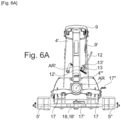
- the crosspiece (17') is mounted, with limited rotation and translation ability, by a pivot/slide connection between two plates arranged under the bracket (4) ( figure 2 , 4C , 5A , 5B And 6A ). Rotation is limited by front and rear stops and translation by the slide.
- the aforementioned single control of the two rotation-blocking locking bolts may for example consist of a handle (17") and the translation-blocking device (18) may comprise a hooking means (18') in the form of a pivoting arm or pawl capable of engaging, under elastic stress, with the translational and rotary guide pivot in the slide of the crosspiece (17'), to lock it in translation in the direction of advance (A).
- the translation-blocking device (18) may comprise a hooking means (18') in the form of a pivoting arm or pawl capable of engaging, under elastic stress, with the translational and rotary guide pivot in the slide of the crosspiece (17'), to lock it in translation in the direction of advance (A).
Landscapes
- Life Sciences & Earth Sciences (AREA)
- Engineering & Computer Science (AREA)
- Mechanical Engineering (AREA)
- Soil Sciences (AREA)
- Environmental Sciences (AREA)
- Zoology (AREA)
- Lifting Devices For Agricultural Implements (AREA)
- Soil Working Implements (AREA)
- Agricultural Machines (AREA)
Description
La présente invention concerne le domaine du machinisme agricole, en particulier des machines portée, semi-portées ou tractées attelées à un véhicule tracteur lors de leur utilisation et leur transport, notamment les charrues du type porté réversible. Dans ce contexte, l'invention porte sur une charrue réversible présentant une sécurité améliorée lors des changements d'agencement ou de configuration, en particulier lors des changements entre les agencements ou configurations de travail et de transport de cette charrue.The present invention relates to the field of agricultural machinery, in particular mounted, semi-mounted or towed machines coupled to a tractor vehicle during their use and transport, in particular plows of the reversible mounted type. In this context, the invention relates to a reversible plow having improved safety when changing arrangements or configurations, in particular when changing between working and transport arrangements or configurations of this plow.
L'invention vise les charrues réversibles du type comprenant, d'une part, un bâti portant des corps de labour et équipé d'au moins une roue et, d'autre part, une tête d'attelage avec une potence et un dispositif d'accrochage à trois points pour son accouplement avec un véhicule tracteur (par le biais d'une bielle supérieure et de deux bras de relevage inférieurs).The invention relates to reversible plows of the type comprising, on the one hand, a frame carrying plowing bodies and equipped with at least one wheel and, on the other hand, a coupling head with a bracket and a device for three-point attachment for coupling with a towing vehicle (via an upper connecting rod and two lower lifting arms).
Le bâti comporte deux groupes de corps de labour, arrangés de part et d'autre pour un travail de labour respectivement à droite ou à gauche par rapport à la direction d'avance, et il est relié à la potence par une liaison pivot définissant un axe de retournement pour le passage réversible d'une configuration de travail à l'autre, par pivotement d'environ un demi-tour et préférentiellement sous l'effet d'un actionneur (cf.
Ce type de charrue peut être transposée, par rotation d'un quart de tour environ du bâti depuis une des configurations de travail, en configuration de transport dans laquelle le point d'accrochage supérieur est mobile par rapport à la potence et la charrue est trainée par traction au niveau des deux points d'accrochage inférieurs et en roulant en appui sur ladite au moins une roue.This type of plow can be transposed, by rotating the frame approximately a quarter turn from one of the working configurations, into a transport configuration in which the upper attachment point is mobile relative to the bracket and the plow is dragged. by traction at the two lower attachment points and by rolling in support of said at least one wheel.
Plus précisément, la charrue occupe alternativement au moins une des positions de travail grâce au dispositif de retournement précité, ces opérations de retournement étant effectuées à l'occasion d'une inversion de la direction d'avance du tracteur dans la parcelle à labourer (allers-retours successifs séparés par des demi-tours).More precisely, the plow alternately occupies at least one of the working positions thanks to the aforementioned turning device, these turning operations being carried out on the occasion of a reversal of the direction of advance of the tractor in the plot to be plowed (go -successive returns separated by half-turns).
D'une manière générale, ces charrues sont portées au cours des déplacements dans les champs et sont, selon leur poids, portées ou traînées lors des déplacements sur route. Pour des charrues présentant un nombre de corps important (généralement plus de 4), la charrue repose partiellement lors des déplacements sur une roue. Il est courant d'utiliser la roue de régulation (qui détermine la profondeur de labour au travail) comme roue de transport, on parle alors de roue combinée (cf.
Lorsque le dispositif de retournement pivote uniquement d'un quart de tour, le bâti passe d'une des positions de travail à la position de transport. Pendant le transport, le poids de la charrue est réparti entre les bras de relevage inférieurs du système d'attelage et la roue combinée, ou la roue de transport spécifique. La bielle supérieure est désaccouplée pour que la charrue puisse être traînée derrière le tracteur, en étant uniquement attachée par les bielles des bras inférieurs du système d'attelage pour épouser les éventuelles dénivellations du terrain. La charrue est alors trainée à l'arrière du tracteur comme une remorque.When the turning device pivots only a quarter turn, the frame moves from one of the working positions to the transport position. During transport, the weight of the plow is distributed between the lower lifting arms of the hitch system and the combined wheel, or the specific transport wheel. The upper link is uncoupled so that the plow can be dragged behind the tractor, being only attached by the links of the lower arms of the hitch system to adapt to any unevenness in the ground. The plow is then dragged behind the tractor like a trailer.
Une fois la charrue dans sa position de transport et la roue appuyée sur le sol, il est nécessaire de bloquer le dispositif de retournement (verrou de retournement) pour empêcher toute rotation involontaire autour de l'axe de retournement, puis de décrocher la bielle supérieure du système d'attelage de la charrue (à savoir le rendre flottant par rapport à la potence). Une fois ces deux opérations réalisées, la charrue trainée peut circuler sur la route.Once the plow is in its transport position and the wheel rests on the ground, it is necessary to block the turning device (turning lock) to prevent any involuntary rotation around the turning axis, then unhook the upper link of the plow hitch system (i.e. making it floating in relation to the stem). Once these two operations have been completed, the trailed plow can travel on the road.
Pour sécuriser cet agencement de transport de la charrue, celle-ci comporte également un premier moyen de blocage en position du point d'accrochage supérieur par rapport à la potence et un second moyen de blocage en rotation de la liaison pivot, donc du retournement du bâti, lesquels sont engagés ou dégagés selon que la charrue est dans un état d'agencement pour le travail ou le transport,To secure this transport arrangement of the plow, the latter also includes a first means of locking in the position of the upper attachment point relative to the bracket and a second means of locking in rotation of the pivot connection, therefore of the overturning of the plow. frame, which are engaged or released depending on whether the plow is in a state of arrangement for work or transport,
Pour libérer simplement la bielle supérieure lorsque la charrue doit être trainée, la charrue peut éventuellement comporter une potence en deux parties, une partie avant et une partie arrière qui sont mobiles en rotation entre elles (cf.
Les deux opérations précitées (1-verrouiller la rotation en position transport puis 2-déverrouiller la bielle supérieure) doivent être réalisées l'une après l'autre et dans cet ordre par l'opérateur.The two aforementioned operations (1-lock the rotation in the transport position then 2-unlock the upper link) must be carried out one after the other and in this order by the operator.
Il y a un risque notable d'accident si l'opérateur néglige l'une des deux opérations et même s'il ne respecte pas l'ordre de succession précité.There is a significant risk of accident if the operator neglects one of the two operations and even if he does not respect the aforementioned order of succession.
Il existe ainsi une demande effective, non satisfaite à ce jour, pour une charrue du type précité dont la mise en position de transport se fait toujours de manière sécurisée, sans risque d'erreur, ni d'oubli, et ce préférentiellement aussi de manière ergonomique.There is thus an effective demand, not satisfied to date, for a plow of the aforementioned type whose placement in the transport position is always done in a secure manner, without risk of error or forgetting, and preferably also in a manner ergonomic.
La présente invention a pour but de répondre à cette demande.The present invention aims to meet this demand.
A cet effet, elle a pour objet une charrue réversible du type mentionné ci-dessus et qui est caractérisée en ce qu'elle comprend en outre un dispositif de commande commune de l'état engagé/dégagé desdits premier et second moyens de blocage, ce dispositif étant configuré de manière à définir un ordre de succession des opérations d'actionnement ou de libération desdits premiers et seconds moyens de blocage respectivement vers leur état engagé ou leur état dégagé selon l'état d'agencement recherché pour la charrueFor this purpose, its object is a reversible plow of the type mentioned above and which is characterized in that it further comprises a device for common control of the engaged/disengaged state of said first and second blocking means, this device being configured so as to define an order of succession of actuation or release operations of said first and second blocking means respectively towards their engaged state or their released state according to the desired arrangement state for the plow
L'invention sera mieux comprise, grâce à la description ci-après, qui se rapporte à un mode de réalisation préféré, donné à titre d'exemple non limitatif, et expliqué avec référence aux dessins schématiques annexés, dans lesquels :
- [
Fig. 1A ] représente une charrue selon une première variante de réalisation de l'invention représentée en configuration de travail pour un labour à droite, ladite charrue présentant une roue combinée ; - [
Fig. 1B ] représente une charrue selon une seconde variante de réalisation de l'invention représentée en configuration de transport, ladite charrue présentant au moins une roue destinée à s'appuyer au sol dans la configuration de transport ; - [
Fig. 2 ] est une vue en perspective d'une tête d'attelage selon l'invention pouvant faire partie de l'une des charrues représentéesfigures 1A et1B ; - [
Fig. 3A ] et - [
Fig. 3B ] sont des vues partielles (la partie inférieure et certains composants étant enlevés), en élévation frontale (selon une direction opposée à la direction d'avance) et en perspective, de la tête d'attelage représentéefigure 2 , montrant plus précisément le dispositif de commande commune des moyens de blocage du point d'accrochage supérieur et de la rotation du bâti (blocage retournement) en accord avec l'invention ; - [
Fig. 4A ], - [
Fig. 4B ] et - [
Fig.4C ] sont des vues partielles (certains composants étant enlevés), respectivement en élévation frontale et en perspective selon deux directions différentes de la tête d'attelage représentée sur lafigure 2 , le dispositif de commande commune étant dans un état associé à une configuration de travail de la charrue ; - [
Fig. 5A ] et - [
Fig. 5B ] sont des vues partielles en perspective et en élévation arrière de la tête d'attelage représentée sur lafigure 2 , le dispositif de commande commune étant dans un état intermédiaire transitoire ; - [
Fig. 6A ] et - [
Fig. 6B ] sont des vues partielles en élévation frontale et en perspective de la tête d'attelage représentée sur lafigure 2 , le dispositif de commande commune étant dans un état associé à une configuration de transport de la charrue ; - [
Fig. 5C ] et - [
Fig. 6C ] sont des vues de détail à une autre échelle d'une partie des objets représentés respectivement sur lafigure 5B (figure 5C ) et sur lesfigures 6A et6B (figure 6C - vue en perspective arrière).
- [
Fig. 1A ] represents a plow according to a first alternative embodiment of the invention shown in working configuration for right-hand plowing, said plow having a combined wheel; - [
Fig. 1B ] represents a plow according to a second alternative embodiment of the invention shown in transport configuration, said plow having at least one wheel intended to rest on the ground in the transport configuration; - [
Fig. 2 ] is a perspective view of a coupling head according to the invention which can be part of one of the plows shownfigures 1A And1B ; - [
Fig. 3A ] And - [
Fig. 3B ] are partial views (the lower part and certain components being removed), in front elevation (in a direction opposite to the direction of advance) and in perspective, of the coupling head shownfigure 2 , showing more precisely the common control device for the means for blocking the upper attachment point and the rotation of the frame (turnover lock) in accordance with the invention; - [
Fig. 4A ], - [
Fig. 4B ] And - [
Fig.4C ] are partial views (certain components being removed), respectively in front elevation and in perspective in two different directions of the coupling head shown on thefigure 2 , the common control device being in a state associated with a working configuration of the plow; - [
Fig. 5A ] And - [
Fig. 5B ] are partial perspective and rear elevation views of the coupling head shown on thefigure 2 , the common control device being in a transient intermediate state; - [
Fig. 6A ] And - [
Fig. 6B ] are partial front elevation and perspective views of the coupling head shown on thefigure 2 , the common control device being in a state associated with a transport configuration of the plow; - [
Fig. 5C ] And - [
Fig. 6C ] are detailed views at another scale of part of the objects represented respectively on theFigure 5B (Figure 5C ) and on thefigures 6A And6B (figure 6C - rear perspective view).
Les
Conformément à l'invention, la charrue (1) comprend en outre un dispositif (11) de commande commune de l'état engagé/dégagé desdits premier et second moyens de blocage (9 et 10), ce dispositif (11) étant configuré de manière à définir un ordre de succession des opérations d'actionnement ou de libération desdits premiers et seconds moyens de blocage (9 et 10) respectivement vers leur état engagé ou leur état dégagé selon la configuration recherchée pour la charrue (1).According to the invention, the plow (1) further comprises a device (11) for common control of the engaged/disengaged state of said first and second blocking means (9 and 10), this device (11) being configured to so as to define an order of succession of actuation or release operations of said first and second blocking means (9 and 10) respectively towards their engaged state or their released state according to the configuration sought for the plow (1).
Grâce aux dispositions spécifiques précitées, et par la commande unique, centralisée et séquentielle fournit par l'invention, il peut garantir que toute rotation du bâti (2) autour de l'axe de retournement (AR) est empêchée en configuration de transport, c'est-à-dire lorsque le point d'accrochage supérieur (5) est libéré et autorisé à se déplacer (par exemple en pivotement par rapport aux points d'accrochage inférieurs 5', 5") par rapport à la potence (4) pour une circulation sur chemin et route. Le dispositif de commande (11) s'étend avantageusement dans un espace situé entre un plan horizontal passant par le point d'accrochage supérieur (5) et un plan horizontal passant par les points d'accrochage inférieurs (5', 5"). Plus précisément, le dispositif de commande (11) s'étend dans l'espace situé entre un plan horizontal passant par le point d'accrochage supérieur (5) et un plan horizontal contenant l'axe de retournement (AR), tel que représenté sur la
La
La
En accord avec un mode de construction avantageux, ressortant des
En vue d'aboutir de manière simple et fiable au séquencement opérationnel recherché, la pièce centrale (13) intègre avantageusement un retard de commande opérationnelle, par exemple sous la forme d'une plage morte cinématique, fixant l'ordre de succession des opérations d'actionnement ou de libération desdits premiers et seconds moyens de blocage (9 et 10). Ces derniers se présentent avantageusement sous la forme de verrous. La plage morte cinématique est associée au premier moyen de blocage (9), concerné en second lieu par la séquence opérationnelle exécutée par la manipulation de l'organe primaire (12), et peut par exemple se présenter sous la forme d'une possibilité de libre déplacement relatif (sans entrainement) entre la pièce centrale (13) et l'organe secondaire (9') associé audit premier organe de blocage (9). L'organe secondaire (9') est relié à la pièce centrale (13), et plus particulièrement au niveau de la plage morte cinématique. La plage morte cinématique est ménagée dans la pièce centrale (13) latéralement par rapport à l'axe de rotation (AR') de la pièce centrale (13). L'organe secondaire (9') est avantageusement une tige disposée verticalement le long de la potence (4).In order to achieve the desired operational sequencing in a simple and reliable manner, the central part (13) advantageously integrates an operational control delay, for example in the form of a kinematic deadband, setting the order of succession of the operations. actuation or release of said first and second blocking means (9 and 10). The latter are advantageously in the form of locks. The kinematic deadband is associated with the first blocking means (9), concerned secondly by the operational sequence executed by the manipulation of the primary member (12), and can for example be presented in the form of a possibility of free relative movement (without drive) between the central part (13) and the secondary member (9') associated with said first blocking member (9). The secondary member (9') is connected to the central part (13), and more particularly at the level of the kinematic deadband. The kinematic deadband is provided in the central part (13) laterally relative to the axis of rotation (AR') of the central part (13). The secondary member (9') is advantageously a rod arranged vertically along the bracket (4).
Préférentiellement, et comme cela ressort des
Selon un mode de réalisation très avantageux de la tête d'attelage (16), montré sur les
En accord avec une autre caractéristique constructive préférée de l'invention, ressortant des
En relation avec les constructions précitées des premier et second moyens de blocage (9 et 10), et conformément à une variante pratique de réalisation préférée du dispositif de commande commune (11), ce dernier comprend un mécanisme de manoeuvre intégrant : i) un organe primaire de manipulation (12) sous la forme d'un levier ou d'une poignée, pouvant être positionné(e) et maintenu(e) dans trois positions discrètes, ii) une biellette (9') reliée au premier moyen de blocage (9) sous la forme d'une anse pivotante configurée pour solidariser mutuellement, dans son état engagé, les parties arrière et avant (4' et 4") de ladite potence (4), iii) une came rotative (10') configurée et arrangée pour interagir avec le second moyen de blocage (10) ou le verrou de blocage en rotation du bâti (2) autour de l'axe de retournement (AR) en vue de l'extraire de son état engagé par défaut et iiii) une pièce centrale (13) sur laquelle est montée le levier ou la poignée (12) et qui est reliée cinématiquement à la biellette (9') et à la came (10'), ladite pièce centrale (13) étant fixée avec faculté de rotation sur la partie arrière (4') de la potence (4).In relation to the aforementioned constructions of the first and second blocking means (9 and 10), and in accordance with a preferred practical alternative embodiment of the common control device (11), the latter comprises an operating mechanism integrating: i) a member primary manipulation (12) in the form of a lever or a handle, which can be positioned and maintained in three discrete positions, ii) a link (9') connected to the first locking means ( 9) in the form of a pivoting handle configured to mutually secure, in its engaged state, the rear and front parts (4' and 4") of said bracket (4), iii) a rotating cam (10') configured and arranged to interact with the second blocking means (10) or the rotation blocking lock of the frame (2) around the turning axis (AR) with a view to extracting it from its engaged state by default and iiii) a central part (13) on which the lever or handle (12) is mounted and which is kinematically connected to the link (9') and to the cam (10'), said central part (13) being fixed with the ability to rotate on the rear part (4') of the stem (4).
Dans le contexte de cette variante pratique de réalisation, il peut en outre être prévu que l'axe de rotation de la came (10') soit confondu avec l'axe de rotation (AR') de la pièce centrale (13). La pièce centrale (13) est montée sur la partie arrière (4') au moyen d'un axe de rotation (AR'). Cette pièce centrale (13) peut notamment se présenter sous la forme d'une plaque découpée, dont le plan est perpendiculaire audit axe de rotation (AR'), et la biellette (9') est avantageusement reliée cinématiquement à ladite plaque (13) au niveau d'un trou oblong (13'), dans lequel peut circuler ladite biellette (9') et qui est préférentiellement en forme d'arc de cercle. Ce trou oblong (13') forme une plage morte cinématique générant un retard de transmission de mouvement lors du déplacement en rotation de ladite plaque (13) sous l'effet du levier ou de la poignée (12). L'axe de rotation (AR') de la pièce centrale (13) est sensiblement parallèle à l'axe de retournement (AR) de la charrue.In the context of this practical alternative embodiment, it can also be provided that the axis of rotation of the cam (10') coincides with the axis of rotation (AR') of the central part (13). The central part (13) is mounted on the rear part (4') by means of an axis of rotation (AR'). This central piece (13) can in particular be in the form of a cut-out plate, the plane of which is perpendicular to said axis of rotation (AR'), and the link (9') is advantageously connected kinematically to said plate (13) at the level of an oblong hole (13'), in which said link (9') can circulate and which is preferably in the shape of an arc of a circle. This oblong hole (13') forms a kinematic deadband generating a delay in transmission of movement during the rotational movement of said plate (13) under the effect of the lever or the handle (12). The axis of rotation (AR') of the central part (13) is substantially parallel to the axis of turning (AR) of the plow.
Ce levier (12) articulée sur la potence (4) est avantageusement situé à une hauteur optimale entre les deux points d'accrochage inférieurs (5', 5") et le point d'accrochage supérieur (5), ce qui le rend facile d'accès en étant positionné ergonomiquement. En outre, du fait même de son extension, ce levier (12) fournit un bras de levier important pour l'entrainement en rotation de la pièce centrale (13) autour de l'axe (AR').This lever (12) articulated on the stem (4) is advantageously located at an optimal height between the two lower hooking points (5', 5") and the upper hooking point (5), which makes it easy access by being ergonomically positioned In addition, due to its extension, this lever (12) provides a significant lever arm for driving the central part (13) in rotation around the axis (AR'. ).
Afin de visualiser et de concrétiser physiquement les trois positions du levier (12), la potence (4) comporte des encoches ou des crans (15) pour la réception (préférentiellement avec calage et sécurisation contre une extraction non intentionnelle) du levier de manipulation (12) dans ses trois positions, correspondant aux trois états possibles du dispositif de commande commune (11). Dans l'exemple de réalisation représenté, les encoches (15) sont ménagées dans une paroi latérale de la partie arrière (4') -par exemple à section en U ou en H- de la potence (4) et sont reliées entre elles par un couloir de circulation pour le levier (12).In order to visualize and physically concretize the three positions of the lever (12), the bracket (4) has notches or notches (15) for receiving (preferably with wedging and securing against unintentional extraction) of the handling lever ( 12) in its three positions, corresponding to the three possible states of the common control device (11). In the embodiment shown, the notches (15) are provided in a side wall of the rear part (4') - for example with a U or H section - of the bracket (4) and are connected together by a circulation corridor for the lever (12).
Avantageusement, et à titre de sécurité de manoeuvre, l'organe primaire de manipulation (12) est sollicité élastiquement vers une position correspondant à un état du dispositif de commande commune (11) dans lequel les premier et second moyens de blocage (9 et 10) sont tous deux engagés. Cette sollicitation peut être effective uniquement lorsque le levier (12) n'est pas logé dans l'une des encoches (c'est-à-dire lorsque le levier est en cours de manoeuvre) et le même élément (12') de sollicitation élastique, agissant par exemple sur la pièce centrale (13), peut aussi assurer le calage sécurisé dudit levier (12) lorsqu'il est reçu dans les différentes encoches (15).Advantageously, and for maneuvering safety, the primary manipulation member (12) is elastically biased towards a position corresponding to a state of the common control device (11) in which the first and second blocking means (9 and 10 ) are both engaged. This loading can only be effective when the lever (12) is not housed in one of the notches (that is to say when the lever is being operated) and the same loading element (12') elastic, acting for example on the central part (13), can also ensure the secure wedging of said lever (12) when it is received in the different notches (15).
Comme le montrent les
Bien entendu, l'invention n'est pas limitée au mode de réalisation décrit et représenté aux dessins annexés. Des modifications restent possibles, notamment du point de vue de la constitution des divers éléments ou par substitution d'équivalents techniques, sans sortir pour autant du domaine de protection de l'invention tel que défini par les revendications annexées.Of course, the invention is not limited to the embodiment described and shown in the accompanying drawings. Modifications remain possible, in particular from the point of view of the constitution of the various elements or by substitution of technical equivalents, without departing from the field of protection of the invention as defined by the appended claims.
Claims (11)
- Reversible plow (1) comprising, on the one hand, a frame (2) carrying plowbodies (3, 3') and equipped with at least one wheel (8, 8') and, on the other hand, a coupling head (16) with a support arm (4) and a three-point hitching device (5, 5', 5") for coupling it to a tractor vehicle,the frame (2) comprising two groups of plowbodies (3, 3'), arranged on either side for right-hand or left-hand plowing respectively in relation to the direction of advance (A), and being connected to the support arm (4) by a pivot connection (6) defining a reversing axis (AR) for reversible switching from one working configuration to the other, by pivoting approximately half a turn, preferably under the effect of an actuator (7),the said plow (1) also being transposable, by rotating the frame (2) by approximately a quarter turn around the reversing axis (AR), from one of the working configurations, to the transport configuration in which the upper hitching point (5) is movable in relation to the support arm (4) and in which the plow (1) can be towed by traction at the two lower hitching points (5', 5") and rolling, supported by the said at least one wheel (8),the said plow (1) also comprising a first means (9) for locking in position the upper hitching point (5) in relation to the support arm (4) and a second means (10) for locking in rotation the pivot connection (6), and therefore the rotation of the frame (2), with locking means are engaged or disengaged depending on whether the plow (1) is in one of the working configurations or in the transport configuration,plow (1) characterized in that it further comprises a device (11) for common control of the engaged/disengaged state of the said first and second locking means (9 and 10), this device (11) being configured so as to define a sequence of operations for actuating or releasing the said first and second locking means (9 and 10) respectively towards their engaged state or their disengaged state according to the desired configuration of the plow (1).
- Plow according to claim 1, characterized in that the device for common control (11) comprises an operating mechanism, articulated and mounted on the support arm (4), with a primary handling element (12), with two secondary actuating or release elements (9', 10'), respectively for the first and second locking means (9 and 10), and with a central part (13) providing the kinematic linkage between the primary element (12) and the two secondary elements (9', 10').
- Plow according to claim 2, characterized in that the central part (13) incorporates an operational control delay, for example in the form of a kinematic dead band, setting the sequence of the actuation or release operations of the said first and second locking means (9 and 10), the latter advantageously being in the form of locks.
- Plow according to any of claims 1 to 3, characterized in that the device for common control (11) is configured to be able to assume three distinct states, corresponding to three respectively corresponding positions of the primary handling element (12), namely, based on successive discrete positions of the said primary handling element (12): a first state associated with the working configuration and in which the first locking means (9) is engaged and the second locking means (10) is disengaged; a second neutral or transitional intermediate state in which the second locking means (10) is engaged and the first locking means (9) remains engaged; and, finally, a third state associated with the transport configuration and in which the first locking means (9) is disengaged and the second locking means (10) is engaged, the first state being associated with a working configuration of the plow (1) and the third state being associated with the transport configuration of the said plow (1).
- Plow according to any one of claims 1 to 4, characterized in that the support arm (4) comprises two component parts (4' and 4"), namely a rear part (4') forming a fixed support arm chassis and a front part (4") forming an articulated arm which pivots with the rear part (4') and carrying the upper hitching point (5), with these two parts (4' and 4") able to be selectively and rigidly connected by the first locking means (9), the latter taking the form of a handle or cap pivotally mounted on the rear part (4'), capable of mutually securing the rear and front parts (4' and 4") opposite their pivot articulation (4") and able to be moved between its engaged and disengaged states under the action of a corresponding secondary element (9') forming part of the device for common control (11).
- Plow according to any one of claims 1 to 5, characterized in that the second locking means (10) consists of a lock, for example a pivoting lock, active in its engaged state, in which it prevents any rotation around the reversing axis (AR), under the effect of its weight or an elastic means, and moved in its disengaged state under the action of a corresponding element (10') forming part of the device for common control (11), for example a rotary cam, with the actuator (7) possibly present being advantageously connected to the frame (2) by a connecting rod (14), and the second locking means (10) locking the said connecting rod (14) in position in its engaged state.
- Plow according to claims 5 and 6, characterized in that the device for common control (11) comprises an operating mechanism incorporating: i) a handling element (12) in the form of a lever or handle, which can be positioned and held in three discrete positions, ii) a tie rod (9') connected to the first locking means (9) in the form of a swivel handle configured to mutually rigidly fasten, in its engaged state, the rear and front parts (4' and 4") of the said support arm (4), iii) a rotary cam (10') configured and arranged to interact with the lock for locking in rotation of the frame (2) around the reversing axis (AR) in order to extract it from its default engaged state, and iiii) a central part (13) on which the lever or the handle (12) is mounted, and which is kinematically connected to the tie rod (9') and to the cam (10'), the said central part (13) being fixed with the possibility of rotation on the rear part (4') of the support arm (4).
- Plow according to claim 7, characterized in that the rotation axis of the cam (10') coincides with the rotation axis (AR') of the central part (13), in that the latter takes the form of a cut-out plate, whose plane is perpendicular to the said rotation axis (AR'), and in that the tie rod (9') is kinematically connected to the said plate (13) at an oblong hole (13'), in which the said tie rod (9') can circulate, forming a kinematic dead band generating a delay in the transmission of movement during the rotational displacement of the said plate (13) under the effect of the lever or handle (12).
- Plow according to claims 4 and 7, characterized in that the support arm (4) has notches or indentations (15) for receiving the operating lever (12) in its three positions, corresponding to the three possible states of the device for common control (11).
- Plow according to any of claims 1 to 9, characterized in that the primary handling element (12) is elastically stressed towards a position corresponding to a state of the device for common control (11) in which the first and second locking means (9 and 10) are both engaged.
- Plow according to any of claims 1 to 10, characterized in that the coupling head (16) comprises a hitching crossbar (17') forming a spreader, and also a rotation locking device (17) for this hitching crossbar (17'), preferably with two locks and a single control, and/or an automatic translational locking device (18) for the said crossbar (17').
Applications Claiming Priority (1)
| Application Number | Priority Date | Filing Date | Title |
|---|---|---|---|
| FR2109486A FR3126841B1 (en) | 2021-09-10 | 2021-09-10 | Reversible plow with improved safety during configuration changes |
Publications (2)
| Publication Number | Publication Date |
|---|---|
| EP4147546A1 EP4147546A1 (en) | 2023-03-15 |
| EP4147546B1 true EP4147546B1 (en) | 2024-07-03 |
Family
ID=78483367
Family Applications (1)
| Application Number | Title | Priority Date | Filing Date |
|---|---|---|---|
| EP22194496.0A Active EP4147546B1 (en) | 2021-09-10 | 2022-09-08 | Reversible plough with improved safety during configuration changes |
Country Status (4)
| Country | Link |
|---|---|
| EP (1) | EP4147546B1 (en) |
| DK (1) | DK4147546T3 (en) |
| ES (1) | ES2986073T3 (en) |
| FR (1) | FR3126841B1 (en) |
Family Cites Families (4)
| Publication number | Priority date | Publication date | Assignee | Title |
|---|---|---|---|---|
| FR2666485B1 (en) | 1990-09-07 | 1994-05-13 | Huard Sa | DEVICE FOR HANGING A TOOL AT THE THREE POINT HITCH OF A TRACTOR. |
| FR2820603B1 (en) | 2001-02-13 | 2003-09-19 | Kuhn Huard Sa | PLOW HAVING A COMBINED WHEEL DAMPED FOR TRANSPORT |
| DE102014110100A1 (en) * | 2014-07-18 | 2016-01-21 | Amazonen-Werke H. Dreyer Gmbh & Co. Kg | reversible plow |
| DE102018115863A1 (en) * | 2018-06-29 | 2020-01-02 | Lemken Gmbh & Co. Kg | Mounted reversible plow with freewheel |
-
2021
- 2021-09-10 FR FR2109486A patent/FR3126841B1/en active Active
-
2022
- 2022-09-08 DK DK22194496.0T patent/DK4147546T3/en active
- 2022-09-08 ES ES22194496T patent/ES2986073T3/en active Active
- 2022-09-08 EP EP22194496.0A patent/EP4147546B1/en active Active
Also Published As
| Publication number | Publication date |
|---|---|
| FR3126841A1 (en) | 2023-03-17 |
| ES2986073T3 (en) | 2024-11-08 |
| EP4147546A1 (en) | 2023-03-15 |
| DK4147546T3 (en) | 2024-09-02 |
| FR3126841B1 (en) | 2023-09-22 |
Similar Documents
| Publication | Publication Date | Title |
|---|---|---|
| EP0452237B1 (en) | Farm machine which detects and intermediate position of a connecting device | |
| EP1965630B1 (en) | Agricultural implement comprising an improved hitch structure | |
| FR2995756A1 (en) | DEVICE FOR HITCHING AN AGRICULTURAL TOOL ON A LIFT SYSTEM THREE POINTS OF AN AGRICULTURAL TRACTOR | |
| EP0556143A1 (en) | Mower with an improved locking device | |
| EP0511922B1 (en) | Mowing machine with pivoting hitch structure | |
| FR2718168A1 (en) | Support device for coupling and uncoupling a front loader. | |
| CA2569799C (en) | Device for coupling a loader to a tractor | |
| FR2993904A1 (en) | Front loader for use in front of four-wheeled tractor of e.g. backhoe, has indicating device indicating that work tools are in identical posture independently of position in height of work tools by aligning rear ends of rod and guide tube | |
| FR2668879A1 (en) | SYSTEM FOR HITCHING BETWEEN A TRACTOR AND A SEMI-RIDED TYPE OF TRAILER. | |
| EP4147546B1 (en) | Reversible plough with improved safety during configuration changes | |
| EP1243464A1 (en) | Load handling apparatus and vehicle including such apparatus | |
| EP2353351A1 (en) | Semi-mounted reversible plough with an additional lifting means | |
| EP4147551B1 (en) | Agricultural machine with a coupling head provided with a translational locking device | |
| EP4147548A1 (en) | Agricultural machine with a coupling head provided with a locking device | |
| EP0804871B1 (en) | Cutting machine | |
| EP0390691B1 (en) | Support wheel for reversible plough, for work and for transport | |
| EP0692179B1 (en) | Seeder with a great working breadth | |
| EP0801887B1 (en) | Cutting machine | |
| FR2647297A1 (en) | ARATORY INSTRUMENT COMPRISING A TOOL COMPOSED OF A CENTRAL ELEMENT IN FRONT OF TWO PIVOTING SIDE ELEMENTS | |
| EP0426588A1 (en) | Improvement for agricultural machines especially for haymaking machines | |
| EP2959759B1 (en) | Agricultural machine provided with a centring device | |
| EP0555113B1 (en) | Semi-mounted reversible plough | |
| EP0986943B1 (en) | Agricultural machine | |
| FR2622761A1 (en) | Coupling connecting rod for agricultural machines the connecting rod being provided with a device for three-point coupling to the hydraulic lifter of a tractor | |
| EP4406392A1 (en) | Plough with limited rotation headstock |
Legal Events
| Date | Code | Title | Description |
|---|---|---|---|
| PUAI | Public reference made under article 153(3) epc to a published international application that has entered the european phase |
Free format text: ORIGINAL CODE: 0009012 |
|
| STAA | Information on the status of an ep patent application or granted ep patent |
Free format text: STATUS: THE APPLICATION HAS BEEN PUBLISHED |
|
| AK | Designated contracting states |
Kind code of ref document: A1 Designated state(s): AL AT BE BG CH CY CZ DE DK EE ES FI FR GB GR HR HU IE IS IT LI LT LU LV MC MK MT NL NO PL PT RO RS SE SI SK SM TR |
|
| P01 | Opt-out of the competence of the unified patent court (upc) registered |
Effective date: 20230622 |
|
| STAA | Information on the status of an ep patent application or granted ep patent |
Free format text: STATUS: REQUEST FOR EXAMINATION WAS MADE |
|
| 17P | Request for examination filed |
Effective date: 20230915 |
|
| RBV | Designated contracting states (corrected) |
Designated state(s): AL AT BE BG CH CY CZ DE DK EE ES FI FR GB GR HR HU IE IS IT LI LT LU LV MC MK MT NL NO PL PT RO RS SE SI SK SM TR |
|
| GRAP | Despatch of communication of intention to grant a patent |
Free format text: ORIGINAL CODE: EPIDOSNIGR1 |
|
| STAA | Information on the status of an ep patent application or granted ep patent |
Free format text: STATUS: GRANT OF PATENT IS INTENDED |
|
| RIC1 | Information provided on ipc code assigned before grant |
Ipc: A01B 73/00 20060101ALI20240130BHEP Ipc: A01B 63/16 20060101ALI20240130BHEP Ipc: A01B 59/043 20060101ALI20240130BHEP Ipc: A01B 3/46 20060101AFI20240130BHEP |
|
| INTG | Intention to grant announced |
Effective date: 20240214 |
|
| GRAS | Grant fee paid |
Free format text: ORIGINAL CODE: EPIDOSNIGR3 |
|
| GRAA | (expected) grant |
Free format text: ORIGINAL CODE: 0009210 |
|
| STAA | Information on the status of an ep patent application or granted ep patent |
Free format text: STATUS: THE PATENT HAS BEEN GRANTED |
|
| AK | Designated contracting states |
Kind code of ref document: B1 Designated state(s): AL AT BE BG CH CY CZ DE DK EE ES FI FR GB GR HR HU IE IS IT LI LT LU LV MC MK MT NL NO PL PT RO RS SE SI SK SM TR |
|
| REG | Reference to a national code |
Ref country code: CH Ref legal event code: EP |
|
| REG | Reference to a national code |
Ref country code: DE Ref legal event code: R096 Ref document number: 602022004301 Country of ref document: DE |
|
| REG | Reference to a national code |
Ref country code: DK Ref legal event code: T3 Effective date: 20240827 |
|
| PGFP | Annual fee paid to national office [announced via postgrant information from national office to epo] |
Ref country code: DE Payment date: 20240927 Year of fee payment: 3 |
|
| PGFP | Annual fee paid to national office [announced via postgrant information from national office to epo] |
Ref country code: DK Payment date: 20240925 Year of fee payment: 3 |
|
| PGFP | Annual fee paid to national office [announced via postgrant information from national office to epo] |
Ref country code: FR Payment date: 20240925 Year of fee payment: 3 |
|
| REG | Reference to a national code |
Ref country code: LT Ref legal event code: MG9D |
|
| PGFP | Annual fee paid to national office [announced via postgrant information from national office to epo] |
Ref country code: NO Payment date: 20240927 Year of fee payment: 3 |
|
| REG | Reference to a national code |
Ref country code: NL Ref legal event code: MP Effective date: 20240703 |
|
| REG | Reference to a national code |
Ref country code: ES Ref legal event code: FG2A Ref document number: 2986073 Country of ref document: ES Kind code of ref document: T3 Effective date: 20241108 |
|
| REG | Reference to a national code |
Ref country code: AT Ref legal event code: UEP Ref document number: 1698784 Country of ref document: AT Kind code of ref document: T Effective date: 20240703 |
|
| PG25 | Lapsed in a contracting state [announced via postgrant information from national office to epo] |
Ref country code: PT Free format text: LAPSE BECAUSE OF FAILURE TO SUBMIT A TRANSLATION OF THE DESCRIPTION OR TO PAY THE FEE WITHIN THE PRESCRIBED TIME-LIMIT Effective date: 20241104 |
|
| PG25 | Lapsed in a contracting state [announced via postgrant information from national office to epo] |
Ref country code: NL Free format text: LAPSE BECAUSE OF FAILURE TO SUBMIT A TRANSLATION OF THE DESCRIPTION OR TO PAY THE FEE WITHIN THE PRESCRIBED TIME-LIMIT Effective date: 20240703 |
|
| PG25 | Lapsed in a contracting state [announced via postgrant information from national office to epo] |
Ref country code: PT Free format text: LAPSE BECAUSE OF FAILURE TO SUBMIT A TRANSLATION OF THE DESCRIPTION OR TO PAY THE FEE WITHIN THE PRESCRIBED TIME-LIMIT Effective date: 20241104 Ref country code: NL Free format text: LAPSE BECAUSE OF FAILURE TO SUBMIT A TRANSLATION OF THE DESCRIPTION OR TO PAY THE FEE WITHIN THE PRESCRIBED TIME-LIMIT Effective date: 20240703 |
|
| PG25 | Lapsed in a contracting state [announced via postgrant information from national office to epo] |
Ref country code: FI Free format text: LAPSE BECAUSE OF FAILURE TO SUBMIT A TRANSLATION OF THE DESCRIPTION OR TO PAY THE FEE WITHIN THE PRESCRIBED TIME-LIMIT Effective date: 20240703 Ref country code: GR Free format text: LAPSE BECAUSE OF FAILURE TO SUBMIT A TRANSLATION OF THE DESCRIPTION OR TO PAY THE FEE WITHIN THE PRESCRIBED TIME-LIMIT Effective date: 20241004 Ref country code: PL Free format text: LAPSE BECAUSE OF FAILURE TO SUBMIT A TRANSLATION OF THE DESCRIPTION OR TO PAY THE FEE WITHIN THE PRESCRIBED TIME-LIMIT Effective date: 20240703 |
|
| PG25 | Lapsed in a contracting state [announced via postgrant information from national office to epo] |
Ref country code: BG Free format text: LAPSE BECAUSE OF FAILURE TO SUBMIT A TRANSLATION OF THE DESCRIPTION OR TO PAY THE FEE WITHIN THE PRESCRIBED TIME-LIMIT Effective date: 20240703 |
|
| PG25 | Lapsed in a contracting state [announced via postgrant information from national office to epo] |
Ref country code: LV Free format text: LAPSE BECAUSE OF FAILURE TO SUBMIT A TRANSLATION OF THE DESCRIPTION OR TO PAY THE FEE WITHIN THE PRESCRIBED TIME-LIMIT Effective date: 20240703 |
|
| PG25 | Lapsed in a contracting state [announced via postgrant information from national office to epo] |
Ref country code: IS Free format text: LAPSE BECAUSE OF FAILURE TO SUBMIT A TRANSLATION OF THE DESCRIPTION OR TO PAY THE FEE WITHIN THE PRESCRIBED TIME-LIMIT Effective date: 20241103 |
|
| PG25 | Lapsed in a contracting state [announced via postgrant information from national office to epo] |
Ref country code: CZ Free format text: LAPSE BECAUSE OF FAILURE TO SUBMIT A TRANSLATION OF THE DESCRIPTION OR TO PAY THE FEE WITHIN THE PRESCRIBED TIME-LIMIT Effective date: 20240703 Ref country code: HR Free format text: LAPSE BECAUSE OF FAILURE TO SUBMIT A TRANSLATION OF THE DESCRIPTION OR TO PAY THE FEE WITHIN THE PRESCRIBED TIME-LIMIT Effective date: 20240703 |
|
| PG25 | Lapsed in a contracting state [announced via postgrant information from national office to epo] |
Ref country code: RS Free format text: LAPSE BECAUSE OF FAILURE TO SUBMIT A TRANSLATION OF THE DESCRIPTION OR TO PAY THE FEE WITHIN THE PRESCRIBED TIME-LIMIT Effective date: 20241003 |
|
| PGFP | Annual fee paid to national office [announced via postgrant information from national office to epo] |
Ref country code: IT Payment date: 20240930 Year of fee payment: 3 Ref country code: ES Payment date: 20241001 Year of fee payment: 3 |
|
| PG25 | Lapsed in a contracting state [announced via postgrant information from national office to epo] |
Ref country code: RS Free format text: LAPSE BECAUSE OF FAILURE TO SUBMIT A TRANSLATION OF THE DESCRIPTION OR TO PAY THE FEE WITHIN THE PRESCRIBED TIME-LIMIT Effective date: 20241003 Ref country code: PL Free format text: LAPSE BECAUSE OF FAILURE TO SUBMIT A TRANSLATION OF THE DESCRIPTION OR TO PAY THE FEE WITHIN THE PRESCRIBED TIME-LIMIT Effective date: 20240703 Ref country code: LV Free format text: LAPSE BECAUSE OF FAILURE TO SUBMIT A TRANSLATION OF THE DESCRIPTION OR TO PAY THE FEE WITHIN THE PRESCRIBED TIME-LIMIT Effective date: 20240703 Ref country code: IS Free format text: LAPSE BECAUSE OF FAILURE TO SUBMIT A TRANSLATION OF THE DESCRIPTION OR TO PAY THE FEE WITHIN THE PRESCRIBED TIME-LIMIT Effective date: 20241103 Ref country code: HR Free format text: LAPSE BECAUSE OF FAILURE TO SUBMIT A TRANSLATION OF THE DESCRIPTION OR TO PAY THE FEE WITHIN THE PRESCRIBED TIME-LIMIT Effective date: 20240703 Ref country code: GR Free format text: LAPSE BECAUSE OF FAILURE TO SUBMIT A TRANSLATION OF THE DESCRIPTION OR TO PAY THE FEE WITHIN THE PRESCRIBED TIME-LIMIT Effective date: 20241004 Ref country code: FI Free format text: LAPSE BECAUSE OF FAILURE TO SUBMIT A TRANSLATION OF THE DESCRIPTION OR TO PAY THE FEE WITHIN THE PRESCRIBED TIME-LIMIT Effective date: 20240703 Ref country code: CZ Free format text: LAPSE BECAUSE OF FAILURE TO SUBMIT A TRANSLATION OF THE DESCRIPTION OR TO PAY THE FEE WITHIN THE PRESCRIBED TIME-LIMIT Effective date: 20240703 Ref country code: BG Free format text: LAPSE BECAUSE OF FAILURE TO SUBMIT A TRANSLATION OF THE DESCRIPTION OR TO PAY THE FEE WITHIN THE PRESCRIBED TIME-LIMIT Effective date: 20240703 |