EP4085866A2 - Marker materials and forms for magnetic marker localization - Google Patents
Marker materials and forms for magnetic marker localization Download PDFInfo
- Publication number
- EP4085866A2 EP4085866A2 EP22176363.4A EP22176363A EP4085866A2 EP 4085866 A2 EP4085866 A2 EP 4085866A2 EP 22176363 A EP22176363 A EP 22176363A EP 4085866 A2 EP4085866 A2 EP 4085866A2
- Authority
- EP
- European Patent Office
- Prior art keywords
- magnetic
- marker
- anisotropy
- susceptibility
- magnetic marker
- Prior art date
- Legal status (The legal status is an assumption and is not a legal conclusion. Google has not performed a legal analysis and makes no representation as to the accuracy of the status listed.)
- Pending
Links
- 230000005291 magnetic effect Effects 0.000 title claims abstract description 258
- 239000003550 marker Substances 0.000 title claims abstract description 218
- 239000000463 material Substances 0.000 title description 88
- 230000004807 localization Effects 0.000 title description 12
- 239000005300 metallic glass Substances 0.000 claims abstract description 14
- XEEYBQQBJWHFJM-UHFFFAOYSA-N Iron Chemical compound [Fe] XEEYBQQBJWHFJM-UHFFFAOYSA-N 0.000 claims description 55
- 229910001220 stainless steel Inorganic materials 0.000 claims description 39
- 229910000859 α-Fe Inorganic materials 0.000 claims description 31
- 239000000696 magnetic material Substances 0.000 claims description 28
- 239000007779 soft material Substances 0.000 claims description 21
- 229910052742 iron Inorganic materials 0.000 claims description 18
- 229910045601 alloy Inorganic materials 0.000 claims description 16
- 239000000956 alloy Substances 0.000 claims description 16
- PXHVJJICTQNCMI-UHFFFAOYSA-N Nickel Chemical compound [Ni] PXHVJJICTQNCMI-UHFFFAOYSA-N 0.000 claims description 12
- -1 iron-nickel-aluminium-cobalt-copper Chemical compound 0.000 claims description 10
- BASFCYQUMIYNBI-UHFFFAOYSA-N platinum Chemical compound [Pt] BASFCYQUMIYNBI-UHFFFAOYSA-N 0.000 claims description 10
- OKTJSMMVPCPJKN-UHFFFAOYSA-N Carbon Chemical compound [C] OKTJSMMVPCPJKN-UHFFFAOYSA-N 0.000 claims description 7
- RTAQQCXQSZGOHL-UHFFFAOYSA-N Titanium Chemical compound [Ti] RTAQQCXQSZGOHL-UHFFFAOYSA-N 0.000 claims description 7
- 229910052719 titanium Inorganic materials 0.000 claims description 7
- 239000010936 titanium Substances 0.000 claims description 7
- PCHJSUWPFVWCPO-UHFFFAOYSA-N gold Chemical compound [Au] PCHJSUWPFVWCPO-UHFFFAOYSA-N 0.000 claims description 6
- 229910052759 nickel Inorganic materials 0.000 claims description 6
- 229920000642 polymer Polymers 0.000 claims description 6
- 229910052799 carbon Inorganic materials 0.000 claims description 5
- 229910017052 cobalt Inorganic materials 0.000 claims description 5
- 239000010941 cobalt Substances 0.000 claims description 5
- GUTLYIVDDKVIGB-UHFFFAOYSA-N cobalt atom Chemical compound [Co] GUTLYIVDDKVIGB-UHFFFAOYSA-N 0.000 claims description 5
- 229910052737 gold Inorganic materials 0.000 claims description 5
- 239000010931 gold Substances 0.000 claims description 5
- 229910001000 nickel titanium Inorganic materials 0.000 claims description 5
- HLXZNVUGXRDIFK-UHFFFAOYSA-N nickel titanium Chemical compound [Ti].[Ti].[Ti].[Ti].[Ti].[Ti].[Ti].[Ti].[Ti].[Ti].[Ti].[Ni].[Ni].[Ni].[Ni].[Ni].[Ni].[Ni].[Ni].[Ni].[Ni].[Ni].[Ni].[Ni].[Ni] HLXZNVUGXRDIFK-UHFFFAOYSA-N 0.000 claims description 5
- 229910052697 platinum Inorganic materials 0.000 claims description 5
- 229950004354 phosphorylcholine Drugs 0.000 claims description 4
- 239000004696 Poly ether ether ketone Substances 0.000 claims description 3
- JUPQTSLXMOCDHR-UHFFFAOYSA-N benzene-1,4-diol;bis(4-fluorophenyl)methanone Chemical compound OC1=CC=C(O)C=C1.C1=CC(F)=CC=C1C(=O)C1=CC=C(F)C=C1 JUPQTSLXMOCDHR-UHFFFAOYSA-N 0.000 claims description 3
- 230000005294 ferromagnetic effect Effects 0.000 claims description 3
- 229910002804 graphite Inorganic materials 0.000 claims description 3
- 239000010439 graphite Substances 0.000 claims description 3
- 230000005298 paramagnetic effect Effects 0.000 claims description 3
- 239000002907 paramagnetic material Substances 0.000 claims description 3
- 229920002530 polyetherether ketone Polymers 0.000 claims description 3
- 229920001296 polysiloxane Polymers 0.000 claims description 3
- 239000007787 solid Substances 0.000 claims description 3
- QTBSBXVTEAMEQO-UHFFFAOYSA-M Acetate Chemical compound CC([O-])=O QTBSBXVTEAMEQO-UHFFFAOYSA-M 0.000 claims description 2
- SOGAXMICEFXMKE-UHFFFAOYSA-N Butylmethacrylate Chemical compound CCCCOC(=O)C(C)=C SOGAXMICEFXMKE-UHFFFAOYSA-N 0.000 claims description 2
- XMWRBQBLMFGWIX-UHFFFAOYSA-N C60 fullerene Chemical class C12=C3C(C4=C56)=C7C8=C5C5=C9C%10=C6C6=C4C1=C1C4=C6C6=C%10C%10=C9C9=C%11C5=C8C5=C8C7=C3C3=C7C2=C1C1=C2C4=C6C4=C%10C6=C9C9=C%11C5=C5C8=C3C3=C7C1=C1C2=C4C6=C2C9=C5C3=C12 XMWRBQBLMFGWIX-UHFFFAOYSA-N 0.000 claims description 2
- 229910000531 Co alloy Inorganic materials 0.000 claims description 2
- 229910000640 Fe alloy Inorganic materials 0.000 claims description 2
- FYYHWMGAXLPEAU-UHFFFAOYSA-N Magnesium Chemical compound [Mg] FYYHWMGAXLPEAU-UHFFFAOYSA-N 0.000 claims description 2
- 229920002614 Polyether block amide Polymers 0.000 claims description 2
- 239000004698 Polyethylene Substances 0.000 claims description 2
- KGWWEXORQXHJJQ-UHFFFAOYSA-N [Fe].[Co].[Ni] Chemical compound [Fe].[Co].[Ni] KGWWEXORQXHJJQ-UHFFFAOYSA-N 0.000 claims description 2
- 239000005312 bioglass Substances 0.000 claims description 2
- 229910021387 carbon allotrope Inorganic materials 0.000 claims description 2
- 229910021400 carbon nanofoam Inorganic materials 0.000 claims description 2
- 239000008209 carbon nanofoam Substances 0.000 claims description 2
- GOECOOJIPSGIIV-UHFFFAOYSA-N copper iron nickel Chemical compound [Fe].[Ni].[Cu] GOECOOJIPSGIIV-UHFFFAOYSA-N 0.000 claims description 2
- 229910000777 cunife Inorganic materials 0.000 claims description 2
- 239000002902 ferrimagnetic material Substances 0.000 claims description 2
- 239000003302 ferromagnetic material Substances 0.000 claims description 2
- 229910003472 fullerene Inorganic materials 0.000 claims description 2
- 229910001291 heusler alloy Inorganic materials 0.000 claims description 2
- 229910052588 hydroxylapatite Inorganic materials 0.000 claims description 2
- UGKDIUIOSMUOAW-UHFFFAOYSA-N iron nickel Chemical compound [Fe].[Ni] UGKDIUIOSMUOAW-UHFFFAOYSA-N 0.000 claims description 2
- 229910052749 magnesium Inorganic materials 0.000 claims description 2
- 239000011777 magnesium Substances 0.000 claims description 2
- 229910000734 martensite Inorganic materials 0.000 claims description 2
- XYJRXVWERLGGKC-UHFFFAOYSA-D pentacalcium;hydroxide;triphosphate Chemical compound [OH-].[Ca+2].[Ca+2].[Ca+2].[Ca+2].[Ca+2].[O-]P([O-])([O-])=O.[O-]P([O-])([O-])=O.[O-]P([O-])([O-])=O XYJRXVWERLGGKC-UHFFFAOYSA-D 0.000 claims description 2
- 229920001652 poly(etherketoneketone) Polymers 0.000 claims description 2
- 229920000052 poly(p-xylylene) Polymers 0.000 claims description 2
- 229920000573 polyethylene Polymers 0.000 claims description 2
- 229910001256 stainless steel alloy Inorganic materials 0.000 claims description 2
- 239000011800 void material Substances 0.000 claims description 2
- 239000000560 biocompatible material Substances 0.000 claims 2
- YHHSONZFOIEMCP-UHFFFAOYSA-O phosphocholine Chemical compound C[N+](C)(C)CCOP(O)(O)=O YHHSONZFOIEMCP-UHFFFAOYSA-O 0.000 claims 2
- 230000004044 response Effects 0.000 description 62
- 210000001519 tissue Anatomy 0.000 description 22
- 238000000034 method Methods 0.000 description 21
- 239000000523 sample Substances 0.000 description 19
- 238000010586 diagram Methods 0.000 description 17
- 239000002245 particle Substances 0.000 description 16
- 238000002604 ultrasonography Methods 0.000 description 11
- 230000000694 effects Effects 0.000 description 9
- 230000003902 lesion Effects 0.000 description 9
- 230000008859 change Effects 0.000 description 8
- 238000003384 imaging method Methods 0.000 description 8
- WTFXARWRTYJXII-UHFFFAOYSA-N iron(2+);iron(3+);oxygen(2-) Chemical compound [O-2].[O-2].[O-2].[O-2].[Fe+2].[Fe+3].[Fe+3] WTFXARWRTYJXII-UHFFFAOYSA-N 0.000 description 8
- 238000000576 coating method Methods 0.000 description 7
- 230000005415 magnetization Effects 0.000 description 7
- 239000011159 matrix material Substances 0.000 description 7
- 229910000697 metglas Inorganic materials 0.000 description 7
- 230000002829 reductive effect Effects 0.000 description 7
- RKDVKSZUMVYZHH-UHFFFAOYSA-N 1,4-dioxane-2,5-dione Chemical compound O=C1COC(=O)CO1 RKDVKSZUMVYZHH-UHFFFAOYSA-N 0.000 description 6
- 206010028980 Neoplasm Diseases 0.000 description 6
- 239000011324 bead Substances 0.000 description 6
- 239000011248 coating agent Substances 0.000 description 6
- 238000001514 detection method Methods 0.000 description 6
- 230000001965 increasing effect Effects 0.000 description 6
- 238000001356 surgical procedure Methods 0.000 description 6
- PAPBSGBWRJIAAV-UHFFFAOYSA-N ε-Caprolactone Chemical compound O=C1CCCCCO1 PAPBSGBWRJIAAV-UHFFFAOYSA-N 0.000 description 6
- JJTUDXZGHPGLLC-IMJSIDKUSA-N 4511-42-6 Chemical compound C[C@@H]1OC(=O)[C@H](C)OC1=O JJTUDXZGHPGLLC-IMJSIDKUSA-N 0.000 description 5
- 238000013461 design Methods 0.000 description 5
- UQSXHKLRYXJYBZ-UHFFFAOYSA-N Iron oxide Chemical compound [Fe]=O UQSXHKLRYXJYBZ-UHFFFAOYSA-N 0.000 description 4
- 229910052779 Neodymium Inorganic materials 0.000 description 4
- KDLHZDBZIXYQEI-UHFFFAOYSA-N Palladium Chemical compound [Pd] KDLHZDBZIXYQEI-UHFFFAOYSA-N 0.000 description 4
- 238000013459 approach Methods 0.000 description 4
- 238000001574 biopsy Methods 0.000 description 4
- 239000000499 gel Substances 0.000 description 4
- JJTUDXZGHPGLLC-UHFFFAOYSA-N lactide Chemical compound CC1OC(=O)C(C)OC1=O JJTUDXZGHPGLLC-UHFFFAOYSA-N 0.000 description 4
- 239000006249 magnetic particle Substances 0.000 description 4
- 229910001105 martensitic stainless steel Inorganic materials 0.000 description 4
- 229910052751 metal Inorganic materials 0.000 description 4
- 239000002184 metal Substances 0.000 description 4
- QEFYFXOXNSNQGX-UHFFFAOYSA-N neodymium atom Chemical compound [Nd] QEFYFXOXNSNQGX-UHFFFAOYSA-N 0.000 description 4
- 230000035699 permeability Effects 0.000 description 4
- 229920001223 polyethylene glycol Polymers 0.000 description 4
- 239000012781 shape memory material Substances 0.000 description 4
- 229910000619 316 stainless steel Inorganic materials 0.000 description 3
- LYCAIKOWRPUZTN-UHFFFAOYSA-N Ethylene glycol Chemical compound OCCO LYCAIKOWRPUZTN-UHFFFAOYSA-N 0.000 description 3
- 230000008901 benefit Effects 0.000 description 3
- 210000000481 breast Anatomy 0.000 description 3
- 239000002131 composite material Substances 0.000 description 3
- 230000003247 decreasing effect Effects 0.000 description 3
- 230000005347 demagnetization Effects 0.000 description 3
- 239000013013 elastic material Substances 0.000 description 3
- 230000002209 hydrophobic effect Effects 0.000 description 3
- 238000002347 injection Methods 0.000 description 3
- 239000007924 injection Substances 0.000 description 3
- 239000000203 mixture Substances 0.000 description 3
- 229920003023 plastic Polymers 0.000 description 3
- 239000004033 plastic Substances 0.000 description 3
- 230000009467 reduction Effects 0.000 description 3
- 150000003839 salts Chemical class 0.000 description 3
- 238000001338 self-assembly Methods 0.000 description 3
- 238000012285 ultrasound imaging Methods 0.000 description 3
- 206010006187 Breast cancer Diseases 0.000 description 2
- 208000026310 Breast neoplasm Diseases 0.000 description 2
- 229910052684 Cerium Inorganic materials 0.000 description 2
- VYZAMTAEIAYCRO-UHFFFAOYSA-N Chromium Chemical compound [Cr] VYZAMTAEIAYCRO-UHFFFAOYSA-N 0.000 description 2
- RYGMFSIKBFXOCR-UHFFFAOYSA-N Copper Chemical compound [Cu] RYGMFSIKBFXOCR-UHFFFAOYSA-N 0.000 description 2
- 229910052692 Dysprosium Inorganic materials 0.000 description 2
- 229910052691 Erbium Inorganic materials 0.000 description 2
- 229910052693 Europium Inorganic materials 0.000 description 2
- 229910052688 Gadolinium Inorganic materials 0.000 description 2
- 229910052689 Holmium Inorganic materials 0.000 description 2
- 229910052765 Lutetium Inorganic materials 0.000 description 2
- ZOKXTWBITQBERF-UHFFFAOYSA-N Molybdenum Chemical compound [Mo] ZOKXTWBITQBERF-UHFFFAOYSA-N 0.000 description 2
- 239000004793 Polystyrene Substances 0.000 description 2
- 239000004372 Polyvinyl alcohol Substances 0.000 description 2
- 229910052777 Praseodymium Inorganic materials 0.000 description 2
- 229910052773 Promethium Inorganic materials 0.000 description 2
- 229910052772 Samarium Inorganic materials 0.000 description 2
- VYPSYNLAJGMNEJ-UHFFFAOYSA-N Silicium dioxide Chemical compound O=[Si]=O VYPSYNLAJGMNEJ-UHFFFAOYSA-N 0.000 description 2
- 229910000639 Spring steel Inorganic materials 0.000 description 2
- 229910052771 Terbium Inorganic materials 0.000 description 2
- 229910052775 Thulium Inorganic materials 0.000 description 2
- 229910052769 Ytterbium Inorganic materials 0.000 description 2
- XLOMVQKBTHCTTD-UHFFFAOYSA-N Zinc monoxide Chemical compound [Zn]=O XLOMVQKBTHCTTD-UHFFFAOYSA-N 0.000 description 2
- 229910052782 aluminium Inorganic materials 0.000 description 2
- 239000004411 aluminium Substances 0.000 description 2
- XAGFODPZIPBFFR-UHFFFAOYSA-N aluminium Chemical compound [Al] XAGFODPZIPBFFR-UHFFFAOYSA-N 0.000 description 2
- 229910052788 barium Inorganic materials 0.000 description 2
- DSAJWYNOEDNPEQ-UHFFFAOYSA-N barium atom Chemical compound [Ba] DSAJWYNOEDNPEQ-UHFFFAOYSA-N 0.000 description 2
- 230000009286 beneficial effect Effects 0.000 description 2
- 229920000249 biocompatible polymer Polymers 0.000 description 2
- 229910052797 bismuth Inorganic materials 0.000 description 2
- JCXGWMGPZLAOME-UHFFFAOYSA-N bismuth atom Chemical compound [Bi] JCXGWMGPZLAOME-UHFFFAOYSA-N 0.000 description 2
- GWXLDORMOJMVQZ-UHFFFAOYSA-N cerium Chemical compound [Ce] GWXLDORMOJMVQZ-UHFFFAOYSA-N 0.000 description 2
- 229910052804 chromium Inorganic materials 0.000 description 2
- 239000011651 chromium Substances 0.000 description 2
- 229920001577 copolymer Polymers 0.000 description 2
- 229910052802 copper Inorganic materials 0.000 description 2
- 239000010949 copper Substances 0.000 description 2
- 239000002537 cosmetic Substances 0.000 description 2
- 239000002889 diamagnetic material Substances 0.000 description 2
- 238000009826 distribution Methods 0.000 description 2
- KBQHZAAAGSGFKK-UHFFFAOYSA-N dysprosium atom Chemical compound [Dy] KBQHZAAAGSGFKK-UHFFFAOYSA-N 0.000 description 2
- UYAHIZSMUZPPFV-UHFFFAOYSA-N erbium Chemical compound [Er] UYAHIZSMUZPPFV-UHFFFAOYSA-N 0.000 description 2
- OGPBJKLSAFTDLK-UHFFFAOYSA-N europium atom Chemical compound [Eu] OGPBJKLSAFTDLK-UHFFFAOYSA-N 0.000 description 2
- 230000006870 function Effects 0.000 description 2
- UIWYJDYFSGRHKR-UHFFFAOYSA-N gadolinium atom Chemical compound [Gd] UIWYJDYFSGRHKR-UHFFFAOYSA-N 0.000 description 2
- KJZYNXUDTRRSPN-UHFFFAOYSA-N holmium atom Chemical compound [Ho] KJZYNXUDTRRSPN-UHFFFAOYSA-N 0.000 description 2
- AMWRITDGCCNYAT-UHFFFAOYSA-L hydroxy(oxo)manganese;manganese Chemical compound [Mn].O[Mn]=O.O[Mn]=O AMWRITDGCCNYAT-UHFFFAOYSA-L 0.000 description 2
- 239000007943 implant Substances 0.000 description 2
- 238000003780 insertion Methods 0.000 description 2
- 230000037431 insertion Effects 0.000 description 2
- 229910052746 lanthanum Inorganic materials 0.000 description 2
- FZLIPJUXYLNCLC-UHFFFAOYSA-N lanthanum atom Chemical compound [La] FZLIPJUXYLNCLC-UHFFFAOYSA-N 0.000 description 2
- 239000007937 lozenge Substances 0.000 description 2
- 210000004072 lung Anatomy 0.000 description 2
- OHSVLFRHMCKCQY-UHFFFAOYSA-N lutetium atom Chemical compound [Lu] OHSVLFRHMCKCQY-UHFFFAOYSA-N 0.000 description 2
- 238000009607 mammography Methods 0.000 description 2
- WPBNNNQJVZRUHP-UHFFFAOYSA-L manganese(2+);methyl n-[[2-(methoxycarbonylcarbamothioylamino)phenyl]carbamothioyl]carbamate;n-[2-(sulfidocarbothioylamino)ethyl]carbamodithioate Chemical compound [Mn+2].[S-]C(=S)NCCNC([S-])=S.COC(=O)NC(=S)NC1=CC=CC=C1NC(=S)NC(=O)OC WPBNNNQJVZRUHP-UHFFFAOYSA-L 0.000 description 2
- 238000005259 measurement Methods 0.000 description 2
- 238000012986 modification Methods 0.000 description 2
- 230000004048 modification Effects 0.000 description 2
- 229910052750 molybdenum Inorganic materials 0.000 description 2
- 239000011733 molybdenum Substances 0.000 description 2
- 239000000178 monomer Substances 0.000 description 2
- 229910000595 mu-metal Inorganic materials 0.000 description 2
- 229910052758 niobium Inorganic materials 0.000 description 2
- 239000010955 niobium Substances 0.000 description 2
- GUCVJGMIXFAOAE-UHFFFAOYSA-N niobium atom Chemical compound [Nb] GUCVJGMIXFAOAE-UHFFFAOYSA-N 0.000 description 2
- 229910052763 palladium Inorganic materials 0.000 description 2
- PYJNAPOPMIJKJZ-UHFFFAOYSA-N phosphorylcholine chloride Chemical compound [Cl-].C[N+](C)(C)CCOP(O)(O)=O PYJNAPOPMIJKJZ-UHFFFAOYSA-N 0.000 description 2
- 229920000117 poly(dioxanone) Polymers 0.000 description 2
- 229920001610 polycaprolactone Polymers 0.000 description 2
- 239000004632 polycaprolactone Substances 0.000 description 2
- 229920002223 polystyrene Polymers 0.000 description 2
- 229920002451 polyvinyl alcohol Polymers 0.000 description 2
- PUDIUYLPXJFUGB-UHFFFAOYSA-N praseodymium atom Chemical compound [Pr] PUDIUYLPXJFUGB-UHFFFAOYSA-N 0.000 description 2
- VQMWBBYLQSCNPO-UHFFFAOYSA-N promethium atom Chemical compound [Pm] VQMWBBYLQSCNPO-UHFFFAOYSA-N 0.000 description 2
- 210000002307 prostate Anatomy 0.000 description 2
- 239000012857 radioactive material Substances 0.000 description 2
- KZUNJOHGWZRPMI-UHFFFAOYSA-N samarium atom Chemical compound [Sm] KZUNJOHGWZRPMI-UHFFFAOYSA-N 0.000 description 2
- 229920000431 shape-memory polymer Polymers 0.000 description 2
- 229910052712 strontium Inorganic materials 0.000 description 2
- CIOAGBVUUVVLOB-UHFFFAOYSA-N strontium atom Chemical compound [Sr] CIOAGBVUUVVLOB-UHFFFAOYSA-N 0.000 description 2
- GZCRRIHWUXGPOV-UHFFFAOYSA-N terbium atom Chemical compound [Tb] GZCRRIHWUXGPOV-UHFFFAOYSA-N 0.000 description 2
- 238000012360 testing method Methods 0.000 description 2
- YFHICDDUDORKJB-UHFFFAOYSA-N trimethylene carbonate Chemical compound O=C1OCCCO1 YFHICDDUDORKJB-UHFFFAOYSA-N 0.000 description 2
- 229910052720 vanadium Inorganic materials 0.000 description 2
- LEONUFNNVUYDNQ-UHFFFAOYSA-N vanadium atom Chemical compound [V] LEONUFNNVUYDNQ-UHFFFAOYSA-N 0.000 description 2
- NAWDYIZEMPQZHO-UHFFFAOYSA-N ytterbium Chemical compound [Yb] NAWDYIZEMPQZHO-UHFFFAOYSA-N 0.000 description 2
- 229910052727 yttrium Inorganic materials 0.000 description 2
- VWQVUPCCIRVNHF-UHFFFAOYSA-N yttrium atom Chemical compound [Y] VWQVUPCCIRVNHF-UHFFFAOYSA-N 0.000 description 2
- HMYDRWZDTWVLGO-UHFFFAOYSA-N (2,2-diethoxy-2-hydroxyethyl) 2-methylprop-2-enoate Chemical compound CCOC(O)(OCC)COC(=O)C(C)=C HMYDRWZDTWVLGO-UHFFFAOYSA-N 0.000 description 1
- URYWXMHZLSZSNE-UHFFFAOYSA-N (2,2-diethoxy-2-methoxyethyl) 2-methylprop-2-enoate Chemical compound CCOC(OCC)(OC)COC(=O)C(C)=C URYWXMHZLSZSNE-UHFFFAOYSA-N 0.000 description 1
- 229920002818 (Hydroxyethyl)methacrylate Polymers 0.000 description 1
- VPVXHAANQNHFSF-UHFFFAOYSA-N 1,4-dioxan-2-one Chemical compound O=C1COCCO1 VPVXHAANQNHFSF-UHFFFAOYSA-N 0.000 description 1
- ODRZAZBEQWAOGU-UHFFFAOYSA-N 1,4-dioxin-2-one Chemical compound O=C1COC=CO1 ODRZAZBEQWAOGU-UHFFFAOYSA-N 0.000 description 1
- OLQFXOWPTQTLDP-UHFFFAOYSA-N 2-(2-hydroxyethoxy)ethyl 2-methylprop-2-enoate Chemical compound CC(=C)C(=O)OCCOCCO OLQFXOWPTQTLDP-UHFFFAOYSA-N 0.000 description 1
- SMZOUWXMTYCWNB-UHFFFAOYSA-N 2-(2-methoxy-5-methylphenyl)ethanamine Chemical compound COC1=CC=C(C)C=C1CCN SMZOUWXMTYCWNB-UHFFFAOYSA-N 0.000 description 1
- DAVVKEZTUOGEAK-UHFFFAOYSA-N 2-(2-methoxyethoxy)ethyl 2-methylprop-2-enoate Chemical compound COCCOCCOC(=O)C(C)=C DAVVKEZTUOGEAK-UHFFFAOYSA-N 0.000 description 1
- NIXOWILDQLNWCW-UHFFFAOYSA-N 2-Propenoic acid Natural products OC(=O)C=C NIXOWILDQLNWCW-UHFFFAOYSA-N 0.000 description 1
- YXYJVFYWCLAXHO-UHFFFAOYSA-N 2-methoxyethyl 2-methylprop-2-enoate Chemical compound COCCOC(=O)C(C)=C YXYJVFYWCLAXHO-UHFFFAOYSA-N 0.000 description 1
- DBCAQXHNJOFNGC-UHFFFAOYSA-N 4-bromo-1,1,1-trifluorobutane Chemical compound FC(F)(F)CCCBr DBCAQXHNJOFNGC-UHFFFAOYSA-N 0.000 description 1
- 240000006995 Abutilon theophrasti Species 0.000 description 1
- NIXOWILDQLNWCW-UHFFFAOYSA-M Acrylate Chemical compound [O-]C(=O)C=C NIXOWILDQLNWCW-UHFFFAOYSA-M 0.000 description 1
- 102000009027 Albumins Human genes 0.000 description 1
- 108010088751 Albumins Proteins 0.000 description 1
- 239000005997 Calcium carbide Substances 0.000 description 1
- 229910000975 Carbon steel Inorganic materials 0.000 description 1
- 241000238366 Cephalopoda Species 0.000 description 1
- 102000008186 Collagen Human genes 0.000 description 1
- 108010035532 Collagen Proteins 0.000 description 1
- 229920002307 Dextran Polymers 0.000 description 1
- 229910000976 Electrical steel Inorganic materials 0.000 description 1
- CWYNVVGOOAEACU-UHFFFAOYSA-N Fe2+ Chemical class [Fe+2] CWYNVVGOOAEACU-UHFFFAOYSA-N 0.000 description 1
- 108010010803 Gelatin Proteins 0.000 description 1
- 230000005355 Hall effect Effects 0.000 description 1
- WOBHKFSMXKNTIM-UHFFFAOYSA-N Hydroxyethyl methacrylate Chemical compound CC(=C)C(=O)OCCO WOBHKFSMXKNTIM-UHFFFAOYSA-N 0.000 description 1
- CERQOIWHTDAKMF-UHFFFAOYSA-M Methacrylate Chemical compound CC(=C)C([O-])=O CERQOIWHTDAKMF-UHFFFAOYSA-M 0.000 description 1
- WHNWPMSKXPGLAX-UHFFFAOYSA-N N-Vinyl-2-pyrrolidone Chemical compound C=CN1CCCC1=O WHNWPMSKXPGLAX-UHFFFAOYSA-N 0.000 description 1
- 240000002853 Nelumbo nucifera Species 0.000 description 1
- 235000006508 Nelumbo nucifera Nutrition 0.000 description 1
- 235000006510 Nelumbo pentapetala Nutrition 0.000 description 1
- 229910000831 Steel Inorganic materials 0.000 description 1
- XTXRWKRVRITETP-UHFFFAOYSA-N Vinyl acetate Chemical compound CC(=O)OC=C XTXRWKRVRITETP-UHFFFAOYSA-N 0.000 description 1
- 230000009471 action Effects 0.000 description 1
- 230000001154 acute effect Effects 0.000 description 1
- 230000002411 adverse Effects 0.000 description 1
- 230000003466 anti-cipated effect Effects 0.000 description 1
- 210000001099 axilla Anatomy 0.000 description 1
- 230000006399 behavior Effects 0.000 description 1
- 230000015572 biosynthetic process Effects 0.000 description 1
- 201000011510 cancer Diseases 0.000 description 1
- 239000002775 capsule Substances 0.000 description 1
- 239000002041 carbon nanotube Substances 0.000 description 1
- 229910021393 carbon nanotube Inorganic materials 0.000 description 1
- 239000010962 carbon steel Substances 0.000 description 1
- 239000001913 cellulose Substances 0.000 description 1
- 229920002678 cellulose Polymers 0.000 description 1
- FQMNUIZEFUVPNU-UHFFFAOYSA-N cobalt iron Chemical compound [Fe].[Co].[Co] FQMNUIZEFUVPNU-UHFFFAOYSA-N 0.000 description 1
- KPLQYGBQNPPQGA-UHFFFAOYSA-N cobalt samarium Chemical compound [Co].[Sm] KPLQYGBQNPPQGA-UHFFFAOYSA-N 0.000 description 1
- 229920001436 collagen Polymers 0.000 description 1
- 210000001072 colon Anatomy 0.000 description 1
- 239000000470 constituent Substances 0.000 description 1
- 238000010276 construction Methods 0.000 description 1
- 238000007334 copolymerization reaction Methods 0.000 description 1
- 238000012217 deletion Methods 0.000 description 1
- 230000037430 deletion Effects 0.000 description 1
- 230000001419 dependent effect Effects 0.000 description 1
- 235000014113 dietary fatty acids Nutrition 0.000 description 1
- 238000005516 engineering process Methods 0.000 description 1
- STVZJERGLQHEKB-UHFFFAOYSA-N ethylene glycol dimethacrylate Substances CC(=C)C(=O)OCCOC(=O)C(C)=C STVZJERGLQHEKB-UHFFFAOYSA-N 0.000 description 1
- 230000005284 excitation Effects 0.000 description 1
- 239000000194 fatty acid Substances 0.000 description 1
- 229930195729 fatty acid Natural products 0.000 description 1
- 150000004665 fatty acids Chemical class 0.000 description 1
- 229910000830 fernico Inorganic materials 0.000 description 1
- 229920000159 gelatin Polymers 0.000 description 1
- 239000008273 gelatin Substances 0.000 description 1
- 235000019322 gelatine Nutrition 0.000 description 1
- 235000011852 gelatine desserts Nutrition 0.000 description 1
- 229920001519 homopolymer Polymers 0.000 description 1
- 239000000017 hydrogel Substances 0.000 description 1
- 230000005661 hydrophobic surface Effects 0.000 description 1
- 230000001939 inductive effect Effects 0.000 description 1
- 208000015181 infectious disease Diseases 0.000 description 1
- 235000000396 iron Nutrition 0.000 description 1
- SZVJSHCCFOBDDC-UHFFFAOYSA-N iron(II,III) oxide Inorganic materials O=[Fe]O[Fe]O[Fe]=O SZVJSHCCFOBDDC-UHFFFAOYSA-N 0.000 description 1
- 125000001449 isopropyl group Chemical group [H]C([H])([H])C([H])(*)C([H])([H])[H] 0.000 description 1
- 244000115189 jing ling hua Species 0.000 description 1
- 239000004816 latex Substances 0.000 description 1
- 229920000126 latex Polymers 0.000 description 1
- 231100000053 low toxicity Toxicity 0.000 description 1
- 210000001165 lymph node Anatomy 0.000 description 1
- 238000001646 magnetic resonance method Methods 0.000 description 1
- 230000005389 magnetism Effects 0.000 description 1
- WJZHMLNIAZSFDO-UHFFFAOYSA-N manganese zinc Chemical compound [Mn].[Zn] WJZHMLNIAZSFDO-UHFFFAOYSA-N 0.000 description 1
- 238000004519 manufacturing process Methods 0.000 description 1
- 229910001092 metal group alloy Inorganic materials 0.000 description 1
- 150000002739 metals Chemical class 0.000 description 1
- QYPPRTNMGCREIM-UHFFFAOYSA-N methylarsonic acid Chemical compound C[As](O)(O)=O QYPPRTNMGCREIM-UHFFFAOYSA-N 0.000 description 1
- 239000011859 microparticle Substances 0.000 description 1
- OKPYIWASQZGASP-UHFFFAOYSA-N n-(2-hydroxypropyl)-2-methylprop-2-enamide Chemical compound CC(O)CNC(=O)C(C)=C OKPYIWASQZGASP-UHFFFAOYSA-N 0.000 description 1
- 239000002103 nanocoating Substances 0.000 description 1
- 239000002114 nanocomposite Substances 0.000 description 1
- 239000002105 nanoparticle Substances 0.000 description 1
- 229910001172 neodymium magnet Inorganic materials 0.000 description 1
- QELJHCBNGDEXLD-UHFFFAOYSA-N nickel zinc Chemical compound [Ni].[Zn] QELJHCBNGDEXLD-UHFFFAOYSA-N 0.000 description 1
- 210000000056 organ Anatomy 0.000 description 1
- 230000001350 orogenic effect Effects 0.000 description 1
- 229910000889 permalloy Inorganic materials 0.000 description 1
- 229920001432 poly(L-lactide) Polymers 0.000 description 1
- 229920002463 poly(p-dioxanone) polymer Polymers 0.000 description 1
- 229920000728 polyester Polymers 0.000 description 1
- 229920000671 polyethylene glycol diacrylate Polymers 0.000 description 1
- 229920002643 polyglutamic acid Polymers 0.000 description 1
- 239000002244 precipitate Substances 0.000 description 1
- 239000011241 protective layer Substances 0.000 description 1
- 230000002285 radioactive effect Effects 0.000 description 1
- 239000000700 radioactive tracer Substances 0.000 description 1
- 229910052761 rare earth metal Inorganic materials 0.000 description 1
- 150000002910 rare earth metals Chemical class 0.000 description 1
- 210000000664 rectum Anatomy 0.000 description 1
- 238000011160 research Methods 0.000 description 1
- 239000012858 resilient material Substances 0.000 description 1
- 230000000717 retained effect Effects 0.000 description 1
- 229910000938 samarium–cobalt magnet Inorganic materials 0.000 description 1
- 238000012216 screening Methods 0.000 description 1
- 230000011218 segmentation Effects 0.000 description 1
- 239000000377 silicon dioxide Substances 0.000 description 1
- 238000005245 sintering Methods 0.000 description 1
- 238000004513 sizing Methods 0.000 description 1
- 210000004872 soft tissue Anatomy 0.000 description 1
- 229910052596 spinel Inorganic materials 0.000 description 1
- 239000011029 spinel Substances 0.000 description 1
- 239000010935 stainless steel Substances 0.000 description 1
- 239000010421 standard material Substances 0.000 description 1
- 239000010959 steel Substances 0.000 description 1
- 235000000346 sugar Nutrition 0.000 description 1
- 150000008163 sugars Chemical class 0.000 description 1
- 229910000601 superalloy Inorganic materials 0.000 description 1
- 230000003075 superhydrophobic effect Effects 0.000 description 1
- 239000000725 suspension Substances 0.000 description 1
- CLZWAWBPWVRRGI-UHFFFAOYSA-N tert-butyl 2-[2-[2-[2-[bis[2-[(2-methylpropan-2-yl)oxy]-2-oxoethyl]amino]-5-bromophenoxy]ethoxy]-4-methyl-n-[2-[(2-methylpropan-2-yl)oxy]-2-oxoethyl]anilino]acetate Chemical compound CC1=CC=C(N(CC(=O)OC(C)(C)C)CC(=O)OC(C)(C)C)C(OCCOC=2C(=CC=C(Br)C=2)N(CC(=O)OC(C)(C)C)CC(=O)OC(C)(C)C)=C1 CLZWAWBPWVRRGI-UHFFFAOYSA-N 0.000 description 1
- 229910052723 transition metal Inorganic materials 0.000 description 1
- 150000003624 transition metals Chemical class 0.000 description 1
- 238000012800 visualization Methods 0.000 description 1
- XLYOFNOQVPJJNP-UHFFFAOYSA-N water Substances O XLYOFNOQVPJJNP-UHFFFAOYSA-N 0.000 description 1
- 239000011787 zinc oxide Substances 0.000 description 1
Images


Classifications
-
- A—HUMAN NECESSITIES
- A61—MEDICAL OR VETERINARY SCIENCE; HYGIENE
- A61B—DIAGNOSIS; SURGERY; IDENTIFICATION
- A61B90/00—Instruments, implements or accessories specially adapted for surgery or diagnosis and not covered by any of the groups A61B1/00 - A61B50/00, e.g. for luxation treatment or for protecting wound edges
- A61B90/39—Markers, e.g. radio-opaque or breast lesions markers
-
- A—HUMAN NECESSITIES
- A61—MEDICAL OR VETERINARY SCIENCE; HYGIENE
- A61B—DIAGNOSIS; SURGERY; IDENTIFICATION
- A61B5/00—Measuring for diagnostic purposes; Identification of persons
- A61B5/05—Detecting, measuring or recording for diagnosis by means of electric currents or magnetic fields; Measuring using microwaves or radio waves
-
- A—HUMAN NECESSITIES
- A61—MEDICAL OR VETERINARY SCIENCE; HYGIENE
- A61B—DIAGNOSIS; SURGERY; IDENTIFICATION
- A61B5/00—Measuring for diagnostic purposes; Identification of persons
- A61B5/43—Detecting, measuring or recording for evaluating the reproductive systems
- A61B5/4306—Detecting, measuring or recording for evaluating the reproductive systems for evaluating the female reproductive systems, e.g. gynaecological evaluations
- A61B5/4312—Breast evaluation or disorder diagnosis
-
- H—ELECTRICITY
- H01—ELECTRIC ELEMENTS
- H01F—MAGNETS; INDUCTANCES; TRANSFORMERS; SELECTION OF MATERIALS FOR THEIR MAGNETIC PROPERTIES
- H01F1/00—Magnets or magnetic bodies characterised by the magnetic materials therefor; Selection of materials for their magnetic properties
- H01F1/01—Magnets or magnetic bodies characterised by the magnetic materials therefor; Selection of materials for their magnetic properties of inorganic materials
- H01F1/03—Magnets or magnetic bodies characterised by the magnetic materials therefor; Selection of materials for their magnetic properties of inorganic materials characterised by their coercivity
- H01F1/032—Magnets or magnetic bodies characterised by the magnetic materials therefor; Selection of materials for their magnetic properties of inorganic materials characterised by their coercivity of hard-magnetic materials
-
- H—ELECTRICITY
- H01—ELECTRIC ELEMENTS
- H01F—MAGNETS; INDUCTANCES; TRANSFORMERS; SELECTION OF MATERIALS FOR THEIR MAGNETIC PROPERTIES
- H01F1/00—Magnets or magnetic bodies characterised by the magnetic materials therefor; Selection of materials for their magnetic properties
- H01F1/01—Magnets or magnetic bodies characterised by the magnetic materials therefor; Selection of materials for their magnetic properties of inorganic materials
- H01F1/03—Magnets or magnetic bodies characterised by the magnetic materials therefor; Selection of materials for their magnetic properties of inorganic materials characterised by their coercivity
- H01F1/12—Magnets or magnetic bodies characterised by the magnetic materials therefor; Selection of materials for their magnetic properties of inorganic materials characterised by their coercivity of soft-magnetic materials
-
- A—HUMAN NECESSITIES
- A61—MEDICAL OR VETERINARY SCIENCE; HYGIENE
- A61B—DIAGNOSIS; SURGERY; IDENTIFICATION
- A61B17/00—Surgical instruments, devices or methods
- A61B2017/00831—Material properties
- A61B2017/00862—Material properties elastic or resilient
-
- A—HUMAN NECESSITIES
- A61—MEDICAL OR VETERINARY SCIENCE; HYGIENE
- A61B—DIAGNOSIS; SURGERY; IDENTIFICATION
- A61B90/00—Instruments, implements or accessories specially adapted for surgery or diagnosis and not covered by any of the groups A61B1/00 - A61B50/00, e.g. for luxation treatment or for protecting wound edges
- A61B90/39—Markers, e.g. radio-opaque or breast lesions markers
- A61B2090/3904—Markers, e.g. radio-opaque or breast lesions markers specially adapted for marking specified tissue
- A61B2090/3908—Soft tissue, e.g. breast tissue
-
- A—HUMAN NECESSITIES
- A61—MEDICAL OR VETERINARY SCIENCE; HYGIENE
- A61B—DIAGNOSIS; SURGERY; IDENTIFICATION
- A61B90/00—Instruments, implements or accessories specially adapted for surgery or diagnosis and not covered by any of the groups A61B1/00 - A61B50/00, e.g. for luxation treatment or for protecting wound edges
- A61B90/39—Markers, e.g. radio-opaque or breast lesions markers
- A61B2090/3925—Markers, e.g. radio-opaque or breast lesions markers ultrasonic
-
- A—HUMAN NECESSITIES
- A61—MEDICAL OR VETERINARY SCIENCE; HYGIENE
- A61B—DIAGNOSIS; SURGERY; IDENTIFICATION
- A61B90/00—Instruments, implements or accessories specially adapted for surgery or diagnosis and not covered by any of the groups A61B1/00 - A61B50/00, e.g. for luxation treatment or for protecting wound edges
- A61B90/39—Markers, e.g. radio-opaque or breast lesions markers
- A61B2090/3954—Markers, e.g. radio-opaque or breast lesions markers magnetic, e.g. NMR or MRI
-
- A—HUMAN NECESSITIES
- A61—MEDICAL OR VETERINARY SCIENCE; HYGIENE
- A61B—DIAGNOSIS; SURGERY; IDENTIFICATION
- A61B90/00—Instruments, implements or accessories specially adapted for surgery or diagnosis and not covered by any of the groups A61B1/00 - A61B50/00, e.g. for luxation treatment or for protecting wound edges
- A61B90/39—Markers, e.g. radio-opaque or breast lesions markers
- A61B2090/3966—Radiopaque markers visible in an X-ray image
-
- A—HUMAN NECESSITIES
- A61—MEDICAL OR VETERINARY SCIENCE; HYGIENE
- A61B—DIAGNOSIS; SURGERY; IDENTIFICATION
- A61B90/00—Instruments, implements or accessories specially adapted for surgery or diagnosis and not covered by any of the groups A61B1/00 - A61B50/00, e.g. for luxation treatment or for protecting wound edges
- A61B90/39—Markers, e.g. radio-opaque or breast lesions markers
- A61B2090/3987—Applicators for implanting markers
-
- A—HUMAN NECESSITIES
- A61—MEDICAL OR VETERINARY SCIENCE; HYGIENE
- A61B—DIAGNOSIS; SURGERY; IDENTIFICATION
- A61B90/00—Instruments, implements or accessories specially adapted for surgery or diagnosis and not covered by any of the groups A61B1/00 - A61B50/00, e.g. for luxation treatment or for protecting wound edges
- A61B90/39—Markers, e.g. radio-opaque or breast lesions markers
- A61B2090/3995—Multi-modality markers
-
- A—HUMAN NECESSITIES
- A61—MEDICAL OR VETERINARY SCIENCE; HYGIENE
- A61B—DIAGNOSIS; SURGERY; IDENTIFICATION
- A61B2562/00—Details of sensors; Constructional details of sensor housings or probes; Accessories for sensors
- A61B2562/02—Details of sensors specially adapted for in-vivo measurements
- A61B2562/0223—Magnetic field sensors
Definitions
- the invention relates generally to the field of markers for medical detection and more specifically to magnetic medical markers.
- WGL wire-guided localization
- ROLL Radioguided Occult Lesion Localization
- Magnetic markers are also used, and they overcome the inconvenience and logistical challenges that arise by using a radioactive material as a marker, and they also avoid the drawbacks of guide-wires.
- magnetic markers are relatively complex to manufacture compared with guide-wires.
- All known marking devices are introduced through a hollow needle or cannula.
- this needle is typically narrow in diameter.
- the small diameter of the needle constrains the marker cross section.
- this dimension is generally 14 to 18 gauge.
- the needle has an internal diameter generally of 0.8mm to 1.5mm but may possibly be as large as 1.8mm for certain needle designs.
- the needle size is typically 11 gauge, with an internal diameter of 2.3 to 2.5 mm.
- the magnetic markers are typically constrained to be less than 1.5mm in diameter. In practice, these size constraints limit the magnetic response and in turn the ease with which the marker can be localised with a magnetic probe. Therefore, a stronger magnetic response is desired.
- Another challenge for magnetic biopsy markers is that to achieve an effective magnetic response, the volume of material needs to be maximised.
- This volume requirement results in a typically shaped marker having a length significantly greater than its diameter.
- Such markers are in the region of 1mm to 12mm, with a length to diameter ratio greater than 5.
- This aspect ratio results in a non-uniform magnetic response with a much stronger signal being obtained when the marker major axis is in line with a probe, and a weaker signal when the marker major axis is transverse to the probe. A more uniform response is generally desired.
- the marker is generally guided to its position and confirmed to be in place under ultrasound or stereotactic x-ray imaging. This means that it is desirable for the marker to be clearly visible under X-ray and ultrasound imaging, and preferably under MRI, which can also be used for this purpose.
- What is needed is a marker that has a small amount of material without reducing the intensity of the detectable signal, and provides a more uniform response from any direction relative to the magnetic probe.
- the present invention addresses this need.
- the invention relates to magnetic markers for surgical use.
- it relates to magnetic markers with a more uniform magnetic response once deployed than would be expected from their geometry prior to deployment.
- markers are provided whose shape is chosen such that they give a more uniform magnetic response.
- markers are provided whose geometrical configuration changes once deployed such that they give a more uniform magnetic response.
- markers are provided whose material composition is chosen such that they give a more uniform magnetic response than would be expected from their geometry prior to deployment.
- the marker is in a non-spherical configuration having a ratio of anisotropy of magnetic susceptibility of less than 9. In yet another embodiment, the marker is in a non-spherical configuration having a ratio of anisotropy of magnetic susceptibility of less than 6. In still yet another embodiment, the marker is in a non-spherical configuration having a ratio of anisotropy of magnetic susceptibility of less than 3. In one embodiment, the non-spherical marker configuration is of the shape selected from the group comprising a cylinder, a cable, a "dumbbell-like" form, a bead and a ball of yarn. In another embodiment, the cylinder bends upon placement in tissue. In yet another embodiment, the non-spherical configuration is faceted.
- the marker is a magnetic marker for marking a site in tissue in the body comprising: a plurality of magnetic components linked by flexible non-magnetic components that compact upon placement in the site.
- the magnetic marker for marking a site in tissue in the body includes a magnetic component of a first shape located within a non-magnetic matrix of a second shape.
- the magnetic marker for marking a site in tissue in the body includes a magnetic material core within a magnetic material sheath.
- one of the core and the sheath is a soft-magnetic material.
- the magnetic marker for marking a site in tissue in the body includes a plurality of magnetic components which self assemble into the magnetic marker following placement of the markers into the body.
- the magnetic components are each encased within a super-hydrophobic coating.
- the magnetic marker for marking a site in tissue in the body includes a magnetic metallic glass.
- SPIO superparamagnetic iron oxide
- Another challenge for magnetic biopsy markers is that to achieve an effective magnetic response, the volume of material needs to be maximised. These requirements result in a typical marker having length significantly greater than the diameter because the marker must be delivered through a needle and smaller needle gauges (diameters) are less painful for patients. Such markers are in the region of 1mm to 12mm, with length to diameter ratio greater than 5. In practice, these size constraints limit the magnetic response and in turn the ease with which the marker can be localised with a magnetic probe. Therefore a stronger response is desired.
- the marker is generally guided to its position and confirmed to be in place under ultrasound or stereotactic x-ray imaging.
- SPIO particles have limited visibility under X-ray imaging but can be made ultrasound visible by combining them in a matrix of echogenic material, for example a polymer.
- magnetic markers overcome the drawbacks of guide-wires and radioactive approaches, there remains a need for a magnetic marker that can be introduced through a narrow needle, gives a strong magnetic response, is visible under X-ray and ultrasound imaging, and can be manufactured simply.
- Magnetic susceptibility can be measured by a range of known methods including the Faraday balance, Gouy balance, the magnetic resonance method, and the inductive method with SQUID magnetometer. Magnetic susceptibility can also be calculated using computer-based finite element magnetic modelling packages such as ANSYS Maxwell (ANSYS Inc., Canonsburg, PA), by modelling the marker in a homogenous field and measuring the distortions caused by the marker which correspond to the magnetic susceptibility. See for example the method described in: " Magnetic Susceptibility Modelling Using ANSYS", K. Bartusek et al., Progress In Electromagnetics Research Symposium Proceedings, Marrakesh, Morocco, Mar. 20-23,2011 .
- ANSYS Maxwell ANSYS Inc., Canonsburg, PA
- a magnetic mass susceptibility can be defined which is the induced magnetic response per unit mass of the material.
- Magnetic mass susceptibility, ⁇ ⁇ k/p where ⁇ is the density of the material and ⁇ ⁇ has units of m 3 /kg. This is a normalized susceptibility and allows the relative susceptibilities of different materials to be compared.
- the magnetic mass susceptibility of 316 stainless steel has a range of approximately is approximately 3.80 ⁇ 10 -7 to 1.27 ⁇ 10 -6
- a permanent Neodymium magnet has a value approximately of 6.67 ⁇ 10 -6
- Super Paramagnetic Iron Oxide (SPIO) based markers have a value of approximately 2.5 ⁇ 10 -5 - 1.0 ⁇ 10 -3 depending on the density of particles in a matrix
- NiZn-ferrites have a range of approximately 3 ⁇ 10 -3 to 1.22 ⁇ 10 -1 . Therefore, the NiZn-ferrites require less material to be detected than SPIO which in turn require less material than permanent Neodymium magnetic material or 316 stainless steel.
- H demag is the 'demagnetisation field'
- N x + N y + N z 1.
- the shape of that marker will affect the ease with which it may be localized.
- the induced field, H marker will therefore also be reduced by a factor of (1 + 1 ⁇ 3 ⁇ ) at any given r , but this reduction will be present irrespective of the orientation of the marker to the magnetizing field H .
- the measured ⁇ ratio of 10.3:1 for a cylinder of aspect ratio 7:1 corresponds to an N ⁇ of approximately 0.48; while the same material in a cylinder of aspect ratio 3.7:1 exhibited an anisotropy ratio ⁇ of approximately 4.7:1, corresponding to an N ⁇ of approximately 0.44.
- the magnetic response depends partly on the mass susceptibility of its constituent material or materials, and partly on the shape of the marker, and for a given shape, the response can change with orientation of the marker.
- the anisotropy of the magnetic response can be calculated by using demagnetization factors as outlined above. However, as demagnetization factors are very difficult to calculate for real shapes, a more practical approach is needed to define the anisotropy of the response.
- the change in magnetic response with orientation for a given marker can be thought of as a change in the 'effective susceptibility' of the marker.
- the underlying susceptibility of the marker material does not change, but the change in magnetic response due to the combination of material, shape and orientation can be defined as if the susceptibility were varying.
- a ratio can be defined of the maximum (effective) magnetic susceptibility to the minimum (effective) magnetic susceptibility. This ratio can be referred to as the anisotropy of the magnetic susceptibility and gives an indication of the uniformity of the magnetic susceptibility response along different axes of the marker or from different directions.
- Anisotropy of magnetic susceptibility Maximum magnetic susceptibility Minimum magnetic susceptibility
- the anisotropy of magnetic susceptibility is also dimensionless. If the anisotropy is 1, the susceptibility is the same from any direction. If the anisotropy is high, the susceptibility is very non-uniform with respect to the orientation of the marker.
- anisotropy of magnetic susceptibility is described in the art and can be measured by a number of methods.
- two types of directional susceptibility meter are described in A. K. Dubey, " Understanding an Orogenic Belt , " Springer Geology: An equal-impedance bridge where the specimen can be inserted into a coil; and a balanced-transformer system where the specimen is placed inside a ferrite ring.
- a further method called a three dimensional magnetic anisotropic susceptibility meter is described in US Patent No. 3,492,566 . In each case, a consistent magnetic field is applied to the sample, and the variation in the induced magnetic response is measured as the sample orientation is varied.
- FIG. 2(C) A further such method is shown in Figure 2(C) in which a susceptometry probe is used to measure the induced magnetic response.
- a susceptometry probe is used to measure the induced magnetic response.
- markers produced from various materials and in various forms had their maximum and minimum signals measured at a fixed distance. Results are shown in Table 3.
- Measuring the anisotropy of magnetic susceptibility using a magnetic susceptibility probe or meter is the ideal approach to defining the uniformity of the magnetic response of a marker.
- the projected area of the marker in any direction can be measured and maximum and minimum projected areas determined.
- a lower projected area indicates a greater focussing effect of the field and visa versa.
- the uniformity of response can thus be defined by the ratio of the minimum projected area to the maximum projected area of the marker out of all the available viewpoints or directions.
- this ratio of projected areas is approximately equal to the shape factor of the marker, which is defined as the ratio of the largest dimension of the marker to its smallest dimension and this too can be used as an approximation to the anisotropy of magnetic susceptibility. Both these geometric methods do not account for variations in the magnetic properties within the marker.
- the term 'anisotropy of magnetic susceptibility' or magnetic anisotropy is used throughout, the term 'projected area anisotropy' or 'ratio of largest to smallest dimension' are understood as alternative interchangeable measures of the uniformity of the magnetic response.
- the anisotropy of magnetic susceptibility can be determined for the marker both before deployment when in the delivery device and after deployment. Where the marker configuration changes, the anisotropy of magnetic susceptibility may have a different value before and after deployment.
- An anisotropy ratio of less than 7 i.e. between 1 and 7
- preferably less than 5 and more preferably less than 3 is desirable. Because the magnetic response reduces with distance exponentially, an anisotropy ratio of less than 2 is close enough to the ideal for practical use.
- An ideal magnetic marker becomes magnetized in the presence of a magnetic field and exhibits no permanent magnetic remanence (retained magnetisation) when the field is removed, or in other words, an ideal marker is magnetically soft, i.e. formed from magnetically soft material or behaving as if it is magnetically soft.
- Magnetically soft is here defined as having a magnetic coercivity, Hc, of less than or equal to 1000 Oe, or preferably less than or equal to 100 Oe or more preferably less than or equal to 50 Oe is desired in various embodiments.
- Hc magnetic coercivity
- the marker is magnetised and follows the dotted curve shown in Fig. 1 , returning via the solid line when the magnetic field is removed or reversed.
- the magnetizing drive field (H) pushes the material along the solid magnetisation curve around the loop once for each cycle.
- the induced field in the material (termed the magnetization, M) is detected by the susceptometer probe, for example the probe of US Publication No. 2011/0133730 .
- Ideal marker materials are soft and have a magnetization curve similar to that in Fig. 1A .
- permanent magnets are magnetically hard, having both a high magnetic remanence and a high magnetic coercivity ( Fig. 1(B) ). They are generally unsuitable for use as a magnetic marker in this application because they can attract or be attracted by other ferromagnetic objects such as surgical tools and because they typically have very low magnetic susceptibility.
- the material used in the magnetic marker should have a relative permeability greater than 100, and preferably greater than 500.
- specialist magnetic materials such as high purity iron or amorphous materials such as metallic glasses are used, relative permeability is greater than 1000 and preferably greater than 5000.
- the marker should have a high magnetic mass susceptibility, ⁇ ⁇ .
- ⁇ ⁇ should be greater than or equal to 0.05 m 3 kg -1 , preferably greater than or equal to 0.1 m 3 kg -1 and more preferably greater than or equal to 1 m 3 kg -1 .
- the use of specialist magnetic materials such as high purity iron or amorphous materials such as metallic glasses allows even higher magnetic mass susceptibilities, and ⁇ ⁇ is preferably greater than 5 m 3 kg -1 and more preferably greater than 10 m 3 kg -1 .
- a spherical marker which is capable of being deployed from the conventional needle described, would be capable of being magnetically localised and provide a perfectly isotropic signal.
- Table 1 shows mass susceptibilities for a number of magnetic materials.
- the detection and localization of these magnetic markers can be performed with a sensitive magnetometer (or susceptometer) which generates an alternating magnetic field, to excite the marker magnetically, and detects the magnetic field signature generated by the marker, as disclosed in US Publication No. 2011/0133730 .
- the marker could also be detected by other techniques such as MRI, magnetic particle imaging, eddy current measurement, hall effect, or magnetotomography.
- the marker comprises superparamagnetic particles.
- Superparamagnetic particles typically contain an iron oxide (magnetite and/or maghaemite) core surrounded by a biocompatible coating such as dextran, carboxydextran, other sugars, albumin, PEG, or biocompatible polymers.
- a biocompatible coating such as dextran, carboxydextran, other sugars, albumin, PEG, or biocompatible polymers.
- the particles' magnetic cores need to be below a critical diameter, typically in the range 3-25nm depending on the material and structure.
- Iron oxide is the preferred material for the superparamagnetic core because of its low toxicity, but there are other materials which could form a superparamagnetic core.
- the material of the core should be one that is capable of being magnetically ordered. It may be a metal, such as cobalt, iron, or nickel; a metal alloy, rare earth and transition metal alloy, M-type or spinel ferrite containing aluminium, barium, bismuth, cerium, chromium, cobalt, copper, dysprosium, erbium, europium, gadolinium, holmium, iron, lanthanum, lutetium, manganese, molybdenum, neodymium, nickel, niobium, palladium, platinum, praseodymium, promethium, samarium, strontium, terbium, thulium, titanium, vanadium, ytterbium, and yttrium or a mixture thereof.
- the core can also be formed by oxidising a combination of an iron(II) salt and another metal salt.
- the metal salts which are beneficial include salts of aluminium, barium, bismuth, cerium, chromium, cobalt, copper, dysprosium, erbium, europium, gadolinium, holmium, iron, lanthanum, lutetium, manganese, molybdenum, neodymium, nickel, niobium, palladium, platinum, praseodymium, promethium, samarium, strontium, terbium, thulium, titanium, vanadium, ytterbium, and yttrium.
- the marker comprises a solid, magnetically soft material to provide a significantly increased magnetic response when being localised with a magnetic susceptometry probe.
- Markers produced from magnetically soft materials can include various paramagnetic, ferromagnetic and ferrimagnetic materials such as iron, nickel, cobalt and their alloys, electrical iron (including FM, consumet electrical iron), silicon-irons (including "A”, “A-FM", “B”, “B-FM", “C” variants) iron-phosphorous, nickel-iron (e.g.
- HyRa alloys HyMu alloys, Hipernom, Parmalloy, Superalloy, Mu-metal), Heusler alloys, Fernico alloys (Iron-Nickel-Cobalt based alloys), Cunife alloys (Copper-Nickel-Iron based alloys), Alcomax alloys (Iron-Nickel-Aluminium-Cobalt-Copper based alloys) various stainless steels from the 300 series (e.g. 302, 304, 316), 400 series (e.g. 410, 416, 420, 430, 440, 446, 470) as well as specialist stainless steel alloys (e.g.
- chrome-iron alloys such as Chrome-Core ® series (Carpenter Technology Corp, Wyomissing PA), martensitic stainless steels), ferrites such as MnZn-ferrites, NiZn-ferrites, MgZn-ferrites, Ba-ferrites, MnMgZn-ferrites, and MgZnCu-ferrites.
- the marker comprises a metallic glass with a very high magnetic mass susceptibility to provide a significantly improved magnetic response.
- Metallic glasses are also known as amorphous metal or bulk metallic glass and include Fe or Co based material such as those produced by Metglas Inc. (Conway, SC) or Neomax Materials Co. Ltd (Osaka, Japan); and magnetic carbon allotropes (e.g. fullerenes, highly oriented pyrolitic graphite, carbon nanofoams, nano-porous carbon).
- metallic glasses examples include but are not limited to: FINEMET, NANOPERM, HITPERM (all Hitachi Metals, Tokyo, Japan), METGLAS #2605, METGLAS #2826, METGLAS #2615, METGLAS #2714A, METGLAS #2605.
- these materials may be coated or contained within a biocompatible or inert material for example Bioglass, diamond-like-carbon (DLC), gold, hydroxyapatite, Iron, magnesium, nitinol, parylene, phosphorylcholine (PC) polymer, Poly-butyl methacrylate (PMBA) and polyethylenevinyl acetate (PEVA), polyethylene, PET, polytetraflouroethyleene (PTFE), PEBAX, PEEK, PEKK, platinum, silicone, titanium and the like.
- a biocompatible or inert material for example Bioglass, diamond-like-carbon (DLC), gold, hydroxyapatite, Iron, magnesium, nitinol, parylene, phosphorylcholine (PC) polymer, Poly-butyl methacrylate (PMBA) and polyethylenevinyl acetate (PEVA), polyethylene, PET, polytetraflouroethyleene (PTFE), PEBAX, PEEK, PEKK, platinum
- a shaped material such as a spring steel or shape memory materials alloys such as Nitinol, and shape memory polymers such as PEO-PET coblock polymers and PEEK could also provide additional function of forming a specific shape on deployment if surrounding or surrounded by a magnetically soft material.
- the magnetic material could further be held within a biocompatible matrix, such as collagen, gelatin and other cellulose base materials, Polyvinyl alcohol (PVA), Polyglyconate, polyester based materials (formed by homopolymerization or copolymerization of one or more of these monomers: glycolide, L-lactide and its isomers, ⁇ -caprolactone, p-dioxanone and trimethylene carbonate (TMC).
- a biocompatible matrix such as collagen, gelatin and other cellulose base materials, Polyvinyl alcohol (PVA), Polyglyconate, polyester based materials (formed by homopolymerization or copolymerization of one or more of these monomers: glycolide, L-lactide and its isomers, ⁇ -caprolactone, p-dioxanone and trimethylene carbonate (TMC).
- PVA Polyvinyl alcohol
- TMC trimethylene carbonate
- These may include homopolymers such as: Poly(L-lactide) Poly(DL-lactide), Poly(TMC), Polycaprolactone (PCL), Polyglycolide (PGA), Poly(glycolide-L-lactide) (PGL), or Poly(p-dioxanone) (PDS); or co-polymers such as: L-Lactide/DL-Lactide, L-lactide/Glycolide, L-lactide/Caprolactone, DL-Lactide/Glycolide, DL-Lactide/Caprolactone, Glycolide/Caprolactone, L-lactide/Glycolide/Caprolactone, DL-Lactide/Glycolide/Caprolactone, Poly(dioxinone co-trim ethylene carbonate-co-glycolide) Glykomer 631 (marketed as Biosyn ® ); or copolymers of these with PDS, hydrogels (from one or more monomers of Hydr
- the implanted marker is made from a single magnetically soft material and the marker is shaped to reduce the anisotropy of the magnetic response.
- This anisotropy is defined as the ratio of the maximum magnetic response to the minimum magnetic response.
- the anisotropy arises in shapes with a long thin aspect ratio because magnetically soft materials focus any magnetic field lines running through them. The focusing effect depends on the amount of material in the direction of the field lines.
- a long thin shape when its long axis is aligned with the field focuses many more field lines through the material than when its long axis is perpendicular to the field lines.
- the result is that the magnetic response measured by a susceptometer is much larger in the direction of the long axis than in the direction of the short axis.
- Table 2 shows anisotropy ratios for a number of cylinders of magnetic material of various sizes.
- Table 2 Ratios of anisotropy of magnetic susceptibility for cylinders of various sizes and materials at a constant distance.
- the anisotropy can be altered. For example, by creating a bend in the marker the anisotropy ratio for a given pre-deployment dimensional ratio can be reduced significantly (Table 3). A 130° included angle surprisingly reduces the ratio from 6.7 to 4.5 and a U bend reduces it further to 2.1. In another example, a 90° bend reduces the ratio from 10.7 to 2.6, and a 60° included angle reduces the ratio further to 1.28. Referring again to Table 2, using a magnetic susceptometer system, similar to that described in US Publication No. 2011/0133730 , markers produced from various materials and in various forms had their maximum and minimum signals measured at a fixed distance.
- the graph shows that there is an optimum angle for a uniform signal when the angle is between 0° and 90°, and more preferably between 0° and 45°.
- Figure 18 shows how the signal varies with the angle of sensing relative to the marker's main axis for markers with different included angles.
- Fig. 2(A) is a graph of the relative change in anisotropy ratio as the included angle of a bend in the marker is reduced. The measurements were taken using the test arrangement in Fig. 2(B) .
- the graph ( Fig. 2A ) shows that there is an optimum angle for a uniform signal when the angle is between 0° and 90°, and more preferably between 0° and 45°.
- Fig. 2(C) is a graph that shows how the signal varies with the angle of sensing relative to the marker's main axis for iron markers with different included angles.
- Fig. 2(D) is a graph that shows how the signal varies with the angle of sensing relative to the marker's main axis for iron markers with different included angles.
- the marker may assume the shape only after it has been deployed so that it can be packed more efficiently into the deployment needle prior to deployment.
- An elastic material or a section of elastic material may be used to facilitate this.
- Such shapes include, but are not limited to the following:
- the implanted marker is made primarily from a magnetically soft material and the marker has a long thin aspect ratio prior to deployment but changes configuration after deployment to a shape with a low anisotropy of the magnetic susceptibility.
- the marker Prior to deployment, the marker may have a length to diameter ratio or shape factor of greater than 5, and a ratio of magnetic anisotropy of susceptibility of greater than 5 or even greater than 7 or 9, such values resulting from the extended length of the marker prior to deployment and being beneficial to increase the volume of marker contained in the needle so as to maximize the magnetic response once deployed.
- the ratio of magnetic anisotropy of susceptibility is less than 5 and preferably less than 3, and ideally 2 or less to provide a more uniform magnetic response.
- the marker is elastically deformable or resiliently deformable such that it elastically or resiliently changes in shape and size from a packed or pre-deployment shape within the needle or deployment device with an associated shape factor, to a post-deployment shape and shape factor.
- the elasticity or resilience may, for example, derive from the use of an elastic or resilient material or from an elastic, resilient or deployable structure or combinations thereof.
- the magnetic marker is elastically or resiliently deformable between a packed configuration having a higher anisotropy of magnetic susceptibility, and a deployed / unpacked configuration having a lower anisotropy of magnetic susceptibility.
- the magnetic marker is elastically or resiliently deformable between a packed configuration having a higher projected area anisotropy ratio, and a deployed / unpacked configuration having a lower projected area anisotropy ratio.
- the deployed or delivered configuration of the marker has an anisotropy of magnetic susceptibility of less than 5, more preferably less than 3 and ideally less than 2 in order to give the most uniform detection signal; while prior to deployment within the delivery device, the marker in its packed configuration has an anisotropy of magnetic susceptibility of greater than 5 and more preferably greater than 7, in order to maximize the volume of material in the marker given the constrained diameter of the delivery device.
- the marker in its packed configuration has a projected area anisotropy ratio of greater than 5 and more preferably greater than 7; but in a deployed / unpacked configuration has a projected area anisotropy ratio of less than 5, more preferably less than 3 and ideally less than 2.
- the marker requires a degree of resilience whereby one dimension (e.g., the diameter perpendicular to the main axis) of the marker changes by a factor of, at least, 1.5 times from its packed value to its deployed value.
- the deployed dimension is larger than the packed dimension by a factor of greater than 2 and more preferably greater than 3 in order to provide a shape factor (ratio of maximum dimension to minimum dimension) close to 1 or 2 on deployment, while still having sufficient material to be detected.
- the magnetic marker in its packed configuration is packed within a delivery device prior to use.
- the delivery device needs to be able to deliver the marker through the skin to mark the tissue area of interest, for example a cancerous lesion.
- Suitable delivery devices include any needle- or cannula-based delivery system, typically comprising a needle and means to propel the marker through the end or out of the side of the needle such as a plunger or stylet.
- the needle is preferably 14 to 18 gauge. This means that the needle has an internal diameter generally of 0.8mm to 1.5mm but may possibly be as large as 1.8mm for certain needle designs. Preferably it is between 1.0 and 1.5mm in diameter. If a vacuum-assisted needle is used, the needle size is typically 11 gauge, with an internal diameter of 2.3 to 2.5 mm.
- Markers that achieve the desired change in anisotropy of the magnetic susceptibility between their packed and unpacked configurations include, but are not limited to the following:
- Markers comprising a plurality of magnetically soft elements joined with hinges as shown in Fig. 8(A)-(G) that deform into shape on deployment (either plastically, pre-stressed or through the action of a shape-memory in the material).
- the greater length of the marker in this embodiment is possible because the shape of the marker in the deployment needle is linear but folds to another configuration upon injection into a site. This reduces the anisotropy by providing a substantially uniform amount of magnetic material in any given axis of the marker.
- the multiple facets also provide superior ultrasound response. It is desirable to have at least 3 elements to obtain a uniform response, and many more may be added, although for complexity the number is preferably less than 20 and more preferably less than 10.
- the hinged and other flexible or resiliently deformable forms may comprise a plurality of smaller magnetic units or components joined by non-magnetic flexible or resiliently deformable links such as plastic or shape memory materials. Combinations of these forms, e.g., bent wire made from multi-strand cable, are also included. As shown in Table 3, a marker of this kind with multiple ball elements and a pre-deployment geometric length: diameter ratio of 8 can have a post-deployment magnetic anisotropy of susceptibility of less than 2.
- Markers comprising a plurality of elements joined with collapsible links between them such that on deployment the elements collapse together to form an amorphous region with a low ratio of magnetic anisotropy of susceptibility.
- the links can be formed from a string-like material such as suture or other polymer.
- the magnetically soft elements are links in a chain that can collapse on itself after deployment.
- Markers comprising a springy or resiliently deformable wire, or cylindrical shape prior to deployment that on deployment forms a structure or wireframe.
- Such structures may include a cylindrical coil, helix, conical coil, spherical coil, random 'ball of yarn', or a polyhedron such as a tetrahedron or part thereof.
- Markers comprising a resiliently deformable looped or shaped coil spring that is compressed prior to deployment and expands upon deployment to a shape with a low ratio of magnetic anisotropy of susceptibility.
- a coil spring shaped into a circle gives a surprisingly low ratio of magnetic anisotropy of susceptibility (Table 3).
- the ratio of the circle diameter to the spring coil diameter is less than 5 in order to maintain a more uniform magnetic response.
- Markers comprising two or more elements connected by a link formed from an elastic or resiliently deformable or springy material such that the elements once deployed spring into a new configuration giving a low magnetic anisotropy of susceptibility.
- Table 4 illustrates one such embodiment comprising two short cylindrical elements formed of magnetically soft material joined by a spring filament.
- the filament is biased such that on deployment the two elements spring back across each other to approximate a tetrahedral shape with a low ratio of magnetic anisotropy of susceptibility of less than 2.
- the spring filament may be formed from a spring steel, shape memory material or other elastic or resiliently deformable material.
- the length of the cylindrical elements is between 2 and 5 times their diameter to provide good uniformity of response combined with a compact shape.
- multiple elements on a springy material are deployed from the needle and the springy material is biased such that on deployment the elements are formed into a structure.
- Example structures may include a cylindrical coil, helix, conical coil, spherical coil, random 'ball of yarn', or a tetrahedron or part thereof.
- the length of the marker when in its packed configuration may be between 2 and 5 times their diameter but could be even greater e.g. up to 10 or more times the diameter depending on the degree of elasticity of the structure of material being used, thus allowing more magnetic material to be deployed to maximize the detectability of the marker.
- a further benefit of the "ball of yarn" ( Fig. 6 ) stranded or multi-facetted forms is superior visibility to such reflective imaging techniques as ultrasound, IR or ultra-wideband radar.
- These benefits can also be realised by revision of the external surface of the other forms mentioned, including the non-hinge sections of the hinged forms ( Fig. 7 ) from cylindrical to facetted or grooved forms such as, but not limited to, triangular, pentagonal, dodecagon, cog-like cross sections ( Fig. 9 ).
- a similar effect can be observed in ultrasound from sintered materials such as ferrites.
- Correct choice of soft material in any of the forms mentioned can provide visibility to X-ray imaging. Interlocked U's take similar space to U but with increased signal and reduced anisotropy ( Fig. 18 ).
- the ratio of magnetic anisotropy of susceptibility of the implanted marker is modified by varying the magnetic properties of the magnetically soft material forming the marker along its length.
- the reduction in magnetic anisotropy of susceptibility can be achieved through use of composite materials such as the formation of ferrite via sintering with two or more materials where at least one material is a soft material distributed to provide a less anisotropic response. Similar forms can be created, as previously mentioned, where multiple materials are used within the marker.
- One such embodiment is a single segmented marker with a constant cross section.
- an additional benefit of this aspect of the invention is that the soft distribution or shape can be independent of the external form and cross sections which improve imaging visibility under ultrasound or X-ray can be created.
- Further examples of composite magnetic markers with decreased anisotropy include soft markers distributed on a collapsible stent-like structure specifically those that are self-expanding.
- embodiments include hollow versions where the individual wires are formed from different materials or formed from composite material, e.g., a core and a covering or sheath material where at least one or more of these are magnetically soft materials.
- a specific example of this is where the core or covering material is made from Nitinol or other shape memory material (including shape memory polymers) which is used to form the post deployment shape ( Fig. 10 ).
- the core or covering material is made from Nitinol or other shape memory material (including shape memory polymers) which is used to form the post deployment shape ( Fig. 10 ).
- the wires or one of the segments multi-core wires could also be used to provide improved X-ray visibility.
- Figs. 12(A) and (B) are examples of segmented marker (note: more or fewer segments are possible).
- the segmentation increases losses between sections in the axial direction and manages the opposing eddy current effect, reducing the anisotropy.
- Figs 13(A) and (B) show examples of soft material (dark grey) that may be moulded into a shape that is independent of the external shape of the marker (note: more than two materials could be used within the construction). Anisotropy is improved by providing more magnetic material in the transverse axis and reducing the opposing eddy current through combination of the materials selected.
- the magnetically soft core is formed from a material with a very high magnetic response such as a metallic glass such that sufficient magnetic response can be obtained from only a very small sphere of the material.
- the core is encased in a protective layer comprising a biocompatible coating or capsule, for example a titanium shell or a biocompatible polymer coating. Because the core is spherical, the ratio of magnetic anisotropy of susceptibility is close to 1.
- Figs. 14 Shaped markers with hinges of plastic/pre-stressed/shape memory in multiple materials with different magnetic properties are shown in Figs. 14 (A-E). These configurations improve the tailoring of the response in order to reduce the anisotropy by providing a substantially uniform response in any given axis of the marker. The multiple facets also provide superior ultrasound response.
- a long thin marker is divided into a number of smaller markers.
- the multiple markers that are packed together prior to deployment have the same overall dimensions and material, and can be used to decrease the anisotropy relative to the overall dimensions of the material.
- 3 ⁇ 2mm long or 2 ⁇ 3mm long or 6 ⁇ 1mm long marker pieces have decreased anisotropy in comparison to 1 ⁇ 6mm long marker of the same outer diameter.
- this reduction in anisotropy occurs even when the segments align one behind each other in the same shape as an individual marker of the combined dimensions.
- Table 5 For example, a single marker of dimension 5mm in ferritic stainless steel gives an anisotropy ratio of 6.7.
- a set of markers or magnetic particles produced from magnetically soft material can retain a small amount of magnetism. Once deployed into the patient, these magnetic particles can then self-assemble into an associated magnetic marker which possesses lower magnetic anisotropy of susceptibility. Multiple magnetically soft markers with a small magnetic remanence will self-assemble into an associated magnetic marker with a substantially uniform amount of material in every direction, thereby minimising anisotropy ( Fig. 15 ). This small magnetic remanence can be overcome by the magnetic excitation of the exciting field of the magnetometer (or susceptometer) as described above. Table 6 shows the parameters of particles assembled by two types of magnetic compositions.
- magnetically soft markers or particles encased within hydrophobic surfaces (nano-texturing via lotus effect, silica nano-coatings, EnBio CoBlast PTFE, Hydroxyapitite, carbon nanotube coatings, precipitate calcium carbide & fatty acid coating with polymer latex, manganese oxide polystyrene or zinc oxide polystyrene nano-composites) or spheres will pull together (self-assemble) on deployment into the patient.
- this embodiment will form a close-packed shape such as a sphere or ellipsoid system which will have an improved magnetic anisotropy of susceptibility relative to the particles within the delivery system which will constrain in an elongated shape to be elongated.
- Fig. 16 depicts hydrophobic coated markers or particles which self-assemble, to minimise surface energy, into an associated magnetic marker with a substantially uniform amount of material in every direction minimising anisotropy.
- small micromarkers or microparticles of a soft material can be suspended within a biocompatible matrix ( Figs. 17(A) and (B) ).
- Control of the magnetic particle distribution in a similar manner as discussed with respect to Figs. 10-12 , allows a decreased magnetic anisotropy of susceptibility as well as the independence from the outer form. It can also be used to ensure a set location and orientation between the magnetic markers.
- the gel and particles can be deployed through the deployment needle ( Fig. 17(B) ).
- the shape of the deployed gel and particles will be constrained only by the injection site (i.e. the tissue of a lesion) which is less in comparison to that of the needle.
- This gel can also set on injection making it less likely to migrate from its deployed location and easier to remove surgically if the tissue is being removed.
- the addition of other particles such as gold to provide additional radiopaque response for x-ray visualisation could be performed if required.
- the anisotropy should be less than or equal to 9, preferably less than or equal to 6, more preferably less than or equal to 3.
- the present invention provides various ways of making magnetic markers with acceptable anisotropy while not affecting the ease of delivery of the particles.
- a method for marking a soft tissue site of interest, such as the site of a tumor or benign lesion for example within the breast, lung, bowel/colon, rectum, prostate or other cancer affected organ, or a lymph node within the axilla or other nodal basin within the body.
- the method includes the steps of (i) inserting such a magnetic marker into tissue near the target lesion or site, and (ii) detecting such a marker using a susceptometer, and optionally (iii) surgically excising the target tissue around the marker.
- the susceptometer detects the marker by providing a magnetic field in the region of the marker and measuring the induced magnetization in the marker.
Landscapes
- Health & Medical Sciences (AREA)
- Life Sciences & Earth Sciences (AREA)
- Surgery (AREA)
- Engineering & Computer Science (AREA)
- Pathology (AREA)
- Veterinary Medicine (AREA)
- Biomedical Technology (AREA)
- Heart & Thoracic Surgery (AREA)
- Medical Informatics (AREA)
- Molecular Biology (AREA)
- Animal Behavior & Ethology (AREA)
- General Health & Medical Sciences (AREA)
- Public Health (AREA)
- Nuclear Medicine, Radiotherapy & Molecular Imaging (AREA)
- Physics & Mathematics (AREA)
- Biophysics (AREA)
- Oral & Maxillofacial Surgery (AREA)
- Radiology & Medical Imaging (AREA)
- Gynecology & Obstetrics (AREA)
- Reproductive Health (AREA)
- Power Engineering (AREA)
- Chemical & Material Sciences (AREA)
- Dispersion Chemistry (AREA)
- Medicines Containing Antibodies Or Antigens For Use As Internal Diagnostic Agents (AREA)
- Materials For Medical Uses (AREA)
- Measurement And Recording Of Electrical Phenomena And Electrical Characteristics Of The Living Body (AREA)
- Magnetic Treatment Devices (AREA)
- Magnetic Resonance Imaging Apparatus (AREA)
- Hard Magnetic Materials (AREA)
- Soft Magnetic Materials (AREA)
- Media Introduction/Drainage Providing Device (AREA)
- Geophysics And Detection Of Objects (AREA)
- Ropes Or Cables (AREA)
- Measurement Of Length, Angles, Or The Like Using Electric Or Magnetic Means (AREA)
Abstract
Description
- This application claims priority from
US Provisional Patent Application 62/170,768 filed on June 4, 2015 - The invention relates generally to the field of markers for medical detection and more specifically to magnetic medical markers.
- With the increasing prevalence of mammography screening programs, the majority of breast cancers are detected as small, non-palpable (or occult) lesions that are amenable to breast conserving treatment. Accurate localization of non-palpable breast cancers is key to allowing surgical removal of the complete tumor with adequate margins. If the tumor is not completely excised, patients need to undergo a further operation to remove any remaining cancerous tissue. Accurate localization also helps to avoid excision of excess breast tissue that could result in adverse cosmetic results. Accurate localization is required by other cancers such as colorectal, prostate and lung, as well as other conditions known by those of ordinary skill in this art.
- The current gold standard for localization of non-palpable lesions during surgery is wire-guided localization (WGL). Although this technique is widely used, WGL has a number of disadvantages. First, it involves two separate procedures, and can present logistical and scheduling difficulties between radiology and surgery departments. Second, the positioning of the guidewire may not be optimal for achieving the desired cosmetic result in the subsequent surgery. Third, the hook wire can migrate away from the site of the lesion or become displaced during mammography or moving the patient. Fourth, the insertion of the wire can be painful for patients and finally, the risk of infection means that surgery usually needs to take place the same day as the wire insertion.
- In order to overcome these disadvantages, other localization techniques have been developed. One such technique is Radioguided Occult Lesion Localization (ROLL) using a radiotracer injected into the tumor and detected by a handheld gamma probe. Although this removes the logistical complexity of WGL, the technique introduces the drawback of the use of radioactive materials, which require special handling and disposal procedures.
- Magnetic markers are also used, and they overcome the inconvenience and logistical challenges that arise by using a radioactive material as a marker, and they also avoid the drawbacks of guide-wires. However, magnetic markers are relatively complex to manufacture compared with guide-wires.
- All known marking devices, including wire guides and magnetic markers, are introduced through a hollow needle or cannula. To minimize patient discomfort, this needle is typically narrow in diameter. The small diameter of the needle constrains the marker cross section. For conventional biopsy needles this dimension is generally 14 to 18 gauge. This means that the needle has an internal diameter generally of 0.8mm to 1.5mm but may possibly be as large as 1.8mm for certain needle designs. If a vacuum-assisted needle is used, the needle size is typically 11 gauge, with an internal diameter of 2.3 to 2.5 mm. Thus, the magnetic markers are typically constrained to be less than 1.5mm in diameter. In practice, these size constraints limit the magnetic response and in turn the ease with which the marker can be localised with a magnetic probe. Therefore, a stronger magnetic response is desired.
- Another challenge for magnetic biopsy markers is that to achieve an effective magnetic response, the volume of material needs to be maximised. This volume requirement results in a typically shaped marker having a length significantly greater than its diameter. Such markers are in the region of 1mm to 12mm, with a length to diameter ratio greater than 5. This aspect ratio results in a non-uniform magnetic response with a much stronger signal being obtained when the marker major axis is in line with a probe, and a weaker signal when the marker major axis is transverse to the probe. A more uniform response is generally desired.
- Further, the marker is generally guided to its position and confirmed to be in place under ultrasound or stereotactic x-ray imaging. This means that it is desirable for the marker to be clearly visible under X-ray and ultrasound imaging, and preferably under MRI, which can also be used for this purpose.
- What is needed is a marker that has a small amount of material without reducing the intensity of the detectable signal, and provides a more uniform response from any direction relative to the magnetic probe.
- The present invention addresses this need.
- The invention relates to magnetic markers for surgical use. In particular, it relates to magnetic markers with a more uniform magnetic response once deployed than would be expected from their geometry prior to deployment.
- In one aspect, markers are provided whose shape is chosen such that they give a more uniform magnetic response.
- In another aspect, markers are provided whose geometrical configuration changes once deployed such that they give a more uniform magnetic response.
- In another aspect, markers are provided whose material composition is chosen such that they give a more uniform magnetic response than would be expected from their geometry prior to deployment.
- In one aspect, the marker is in a non-spherical configuration having a ratio of anisotropy of magnetic susceptibility of less than 9. In yet another embodiment, the marker is in a non-spherical configuration having a ratio of anisotropy of magnetic susceptibility of less than 6. In still yet another embodiment, the marker is in a non-spherical configuration having a ratio of anisotropy of magnetic susceptibility of less than 3. In one embodiment, the non-spherical marker configuration is of the shape selected from the group comprising a cylinder, a cable, a "dumbbell-like" form, a bead and a ball of yarn. In another embodiment, the cylinder bends upon placement in tissue. In yet another embodiment, the non-spherical configuration is faceted.
- In one embodiment, the marker is a magnetic marker for marking a site in tissue in the body comprising: a plurality of magnetic components linked by flexible non-magnetic components that compact upon placement in the site. In another embodiment, the magnetic marker for marking a site in tissue in the body includes a magnetic component of a first shape located within a non-magnetic matrix of a second shape. In yet another embodiment, the magnetic marker for marking a site in tissue in the body includes a magnetic material core within a magnetic material sheath. In still another embodiment, one of the core and the sheath is a soft-magnetic material.
- In one embodiment, the magnetic marker for marking a site in tissue in the body includes a plurality of magnetic components which self assemble into the magnetic marker following placement of the markers into the body. In another embodiment, the magnetic components are each encased within a super-hydrophobic coating. In still yet another embodiment, the magnetic marker for marking a site in tissue in the body includes a magnetic metallic glass.
- The structure and function of the invention can be best understood from the description herein in conjunction with the accompanying figures. The figures are not necessarily to scale, emphasis instead generally being placed upon illustrative principles. The figures are to be considered illustrative in all aspects and are not intended to limit the invention, the scope of which is defined only by the claims.
-
Figs. 1(A) and (B) are magnetization curves for soft and hard magnetic material respectively; -
Fig. 2(A) is a graph of the influence of marker bend angle on anisotropy of susceptibility of a marker; -
Fig. 2(B) is a diagram of an embodiment of a test arrangement for measuring magnetic anisotropy of a marker; -
Fig.2(C) is a signal at a constant distance from 5mm Iron (99.5%) markers with various inclusive angles, where 180-degrees is a straight cylinder and 0-degrees is U-shaped; -
Fig. 2(D) is a graph of a signal at a constant distance from 7mm multi-stand stainless steel markers with various inclusive angles, where 180-degrees is a straight cylinder and 0-degrees is U-shaped; -
Fig. 3(A) is a diagram of an embodiment of the invention in the form of a "lozenge" or a "bead"; -
Figs. 3(B) and (C) are cross-sections of magnetic beads with shaped ends; -
Figs. 4(A)-(D) are diagrams of embodiments of the invention in the form of "dumbbell" shapes; -
Figs. 5(A) and (B) are diagrams of cross-sections of embodiments of the invention in cable form; -
Figs. 6(A) and 6(B) are diagrams of an embodiment of the invention in the shape of a "ball of yarn"; -
Fig. 7 is a diagram of an embodiment of the invention in the shape of a "Chinese lantern"; -
Figs. 8 (A)-(G) are diagrams of embodiments of the invention with hinged linkages; -
Fig. 9 is a collection of diagrams of cross-sections of embodiments of markers of the invention with increased numbers of faces; -
Fig. 10 is a diagram of the cross-section of an embodiment of the invention in the form of core and sheath; -
Fig. 11 is a diagram of the drawing of an embodiment of the invention having a sheath and multiple cores; -
Figs. 12(A) and (B) are diagrams of embodiments of the invention as segmented markers; -
Figs. 13 (A), (B) and (C) are diagrams of embodiments of the invention in which the shape of the magnetic material and the external shape of the marker are different; -
Figs. 14 (A)-(E) are diagrams of embodiments of the invention in the form of shaped markers with hinges made of various materials; -
Fig. 15 is a diagram of an embodiment of the invention constructed by self assembly; -
Fig. 16 is a diagram of an embodiment of the invention constructed by hydrophobic self-assembly; -
Figs. 17 (A) and (B) are diagrams of other embodiments of the invention constructed by self-assembly; -
Fig. 18 is a diagram of an embodiment of two interlocking U shaped markers. - A method for making magnetic markers as permanent magnets is described in
US Patent No. 6,173,715 . Permanent magnet implants have the drawback that they will attract any magnetic material in the vicinity and therefore could interact undesirably with other implants, or move in the tissue, for example, when a surgical tool made from magnetic material is nearby. - A method for making markers formed from superparamagnetic iron oxide (SPIO) nanoparticles in bioabsorbable form is described in
US Publication No. 2014/0314679 . SPIO particles avoid the concerns that occur for permanent magnetic markers because such materials have no magnetic remanence, and are not magnetic in themselves, but only become magnetized when in the presence of a magnetic field. The detection and localization of these SPIO magnetic markers can be performed with a sensitive magnetometer (or susceptometer) that generates an alternating magnetic field to excite the marker magnetically, and detects the magnetic field signature generated by the marker, as disclosed inUS Publication No. 2011/0133730 . - Another challenge for magnetic biopsy markers is that to achieve an effective magnetic response, the volume of material needs to be maximised. These requirements result in a typical marker having length significantly greater than the diameter because the marker must be delivered through a needle and smaller needle gauges (diameters) are less painful for patients. Such markers are in the region of 1mm to 12mm, with length to diameter ratio greater than 5. In practice, these size constraints limit the magnetic response and in turn the ease with which the marker can be localised with a magnetic probe. Therefore a stronger response is desired.
- Further, the marker is generally guided to its position and confirmed to be in place under ultrasound or stereotactic x-ray imaging. This means that it is desirable for the marker to be clearly visible under X-ray and ultrasound imaging, and preferably under MRI, which can also be used for this purpose. SPIO particles have limited visibility under X-ray imaging but can be made ultrasound visible by combining them in a matrix of echogenic material, for example a polymer. Although magnetic markers overcome the drawbacks of guide-wires and radioactive approaches, there remains a need for a magnetic marker that can be introduced through a narrow needle, gives a strong magnetic response, is visible under X-ray and ultrasound imaging, and can be manufactured simply.
- The requirement for the marker to be magnetically localisable requires a certain magnetic response from the implanted material, and for this response to be measurable at a distance removed from the material. This response is related to the magnetic susceptibility parameter. In SI units the magnetic susceptibility is a dimensionless proportionality constant that indicates the degree of magnetization induced in a material in response to an applied magnetic field, and is defined by:

- Magnetic susceptibility can be measured by a range of known methods including the Faraday balance, Gouy balance, the magnetic resonance method, and the inductive method with SQUID magnetometer. Magnetic susceptibility can also be calculated using computer-based finite element magnetic modelling packages such as ANSYS Maxwell (ANSYS Inc., Canonsburg, PA), by modelling the marker in a homogenous field and measuring the distortions caused by the marker which correspond to the magnetic susceptibility. See for example the method described in: "Magnetic Susceptibility Modelling Using ANSYS", K. Bartusek et al., Progress In Electromagnetics Research Symposium Proceedings, Marrakesh, Morocco, Mar. 20-23,2011.
- For a given material, a magnetic mass susceptibility can be defined which is the induced magnetic response per unit mass of the material. Magnetic mass susceptibility, χρ =k/p where ρ is the density of the material and χρ has units of m3/kg. This is a normalized susceptibility and allows the relative susceptibilities of different materials to be compared. For example, the magnetic mass susceptibility of 316 stainless steel, a standard material for biopsy markers, has a range of approximately is approximately 3.80×10⁻⁷ to 1.27×10⁻⁶, a permanent Neodymium magnet has a value approximately of 6.67×10⁻⁶, Super Paramagnetic Iron Oxide (SPIO) based markers have a value of approximately 2.5 ×10⁻⁵ - 1.0×10⁻³ depending on the density of particles in a matrix, while NiZn-ferrites have a range of approximately 3×10⁻³ to 1.22×10⁻¹. Therefore, the NiZn-ferrites require less material to be detected than SPIO which in turn require less material than permanent Neodymium magnetic material or 316 stainless steel.
- For a magnetically soft marker of volume V, subject to a field H in the linear susceptibility region, the total induced moment on the marker will be m = M V = χ V H. This moment will give rise to its own magnetic field H marker which at a distance removed from the marker may be approximated as that due to an equivalent point dipole moment, namely:

- However, there are other factors that may affect the ease with which a given marker may be located - or in other words, affect the strength of the induced field, H marker, at a given r. One of these is known as 'demagnetization'. This is a phenomenon that occurs in objects of finite size, where the induced field due to the magnetization in one part of the body acts to demagnetize another part of the same body. The effect is very complex to predict in other than the most simple geometries, and is therefore most often described, as here, for the special case of the object being an ellipsoid of revolution (e.g. a sphere, cylinder or disk). In such a case, the induced magnetization within the object is uniform, and the local magnetic field is commonly written:


- In SI units Nx + Ny + Nz = 1. For the case of a sphere, Nx = Ny = Nz = ⅓. For the case of a long z-axis cylinder, Nx = Ny = ½ and Nz = 0. For the case of a thin xy-plane disk, Nx = Ny = 0 and Nz = 1. In the case of a marker made from a given single material of a given mass, the shape of that marker will affect the ease with which it may be localized.
- For example: if the marker is made into a sphere, it will experience H local = H - ⅓ M, irrespective of the orientation of the marker to the applied field. The induced moment will therefore be:

- The induced field, H marker, will therefore also be reduced by a factor of (1 + ⅓ χ) at any given r, but this reduction will be present irrespective of the orientation of the marker to the magnetizing field H.
- In contrast: if the marker were made into a cylinder, then if H was directed perpendicular to the long axis of the cylinder, then H marker would be reduced by a factor of (1 + ½ χ), whereas if H was directed along the long axis, H marker would not be reduced at all. In this case the ratio ξ = (1 + ½ χ) / 1 represents the anisotropic localization signal that the cylinder would present to any method dependent on the magnitude of H marker for its signal strength.
- In the case of a cylinder of finite length, this ratio may be approximated as:

- Thus, for a magnetic marker, the magnetic response depends partly on the mass susceptibility of its constituent material or materials, and partly on the shape of the marker, and for a given shape, the response can change with orientation of the marker. The anisotropy of the magnetic response can be calculated by using demagnetization factors as outlined above. However, as demagnetization factors are very difficult to calculate for real shapes, a more practical approach is needed to define the anisotropy of the response. The change in magnetic response with orientation for a given marker can be thought of as a change in the 'effective susceptibility' of the marker. The underlying susceptibility of the marker material does not change, but the change in magnetic response due to the combination of material, shape and orientation can be defined as if the susceptibility were varying.
- Thus, for any given marker, a ratio can be defined of the maximum (effective) magnetic susceptibility to the minimum (effective) magnetic susceptibility. This ratio can be referred to as the anisotropy of the magnetic susceptibility and gives an indication of the uniformity of the magnetic susceptibility response along different axes of the marker or from different directions.

- As magnetic susceptibility is dimensionless, the anisotropy of magnetic susceptibility, being a ratio of two dimensionless quantities, is also dimensionless. If the anisotropy is 1, the susceptibility is the same from any direction. If the anisotropy is high, the susceptibility is very non-uniform with respect to the orientation of the marker.
- The concept of anisotropy of magnetic susceptibility is described in the art and can be measured by a number of methods. For example, two types of directional susceptibility meter are described in A. K. Dubey, "Understanding an Orogenic Belt," Springer Geology: An equal-impedance bridge where the specimen can be inserted into a coil; and a balanced-transformer system where the specimen is placed inside a ferrite ring. A further method called a three dimensional magnetic anisotropic susceptibility meter is described in
US Patent No. 3,492,566 . In each case, a consistent magnetic field is applied to the sample, and the variation in the induced magnetic response is measured as the sample orientation is varied. A further such method is shown inFigure 2(C) in which a susceptometry probe is used to measure the induced magnetic response. Using a magnetic susceptometer system, similar to that described inUS Publication No. 2011/0133730 , markers produced from various materials and in various forms had their maximum and minimum signals measured at a fixed distance. Results are shown in Table 3. - Measuring the anisotropy of magnetic susceptibility using a magnetic susceptibility probe or meter is the ideal approach to defining the uniformity of the magnetic response of a marker. However, there are alternative approaches to determining the level of anisotropy of magnetic susceptibility. For example, the projected area of the marker in any direction can be measured and maximum and minimum projected areas determined. For a given volume of marker material, a lower projected area indicates a greater focussing effect of the field and visa versa. As the focussing effect is inversely proportional to the projected area, the uniformity of response can thus be defined by the ratio of the minimum projected area to the maximum projected area of the marker out of all the available viewpoints or directions. This is the projected area anisotropy ratio of the magnetic marker, and provides a useful approximation to the anisotropy of magnetic susceptibility. A spherical marker would have a ratio of the minimum projected area to the maximum projected area = 1. A rod shaped marker of diameter, d = 0.75 and length, l = 7.5 would have a ratio of d × 1 / (pi × d2/4) = 12.7.
- It can also be seen that this ratio of projected areas is approximately equal to the shape factor of the marker, which is defined as the ratio of the largest dimension of the marker to its smallest dimension and this too can be used as an approximation to the anisotropy of magnetic susceptibility. Both these geometric methods do not account for variations in the magnetic properties within the marker.
- Where the term 'anisotropy of magnetic susceptibility' or magnetic anisotropy is used throughout, the term 'projected area anisotropy' or 'ratio of largest to smallest dimension' are understood as alternative interchangeable measures of the uniformity of the magnetic response.
- The anisotropy of magnetic susceptibility can be determined for the marker both before deployment when in the delivery device and after deployment. Where the marker configuration changes, the anisotropy of magnetic susceptibility may have a different value before and after deployment.
- From a practical perspective, during surgery to detect the marker using a magnetic probe as described in
WO2014/013235 , high anisotropy is undesirable: the magnetic signal at a constant distance will vary depending on the orientation of the marker relative to the probe and make the marker appear to be closer when approaching from some orientations and further away from others. Minimising the anisotropy for the implanted marker improves the surgeons' ability to localise the marker by making it more intuitive and increases the surgeons' ability to remove a safe margin of tissue around a lesion. An anisotropy ratio of 1 is the ideal, giving a uniform response from any direction. However, in practice this is challenging to achieve within the geometric constraints of delivery through a small needle as outlined herein. An anisotropy ratio of less than 7 (i.e. between 1 and 7), preferably less than 5 and more preferably less than 3 is desirable. Because the magnetic response reduces with distance exponentially, an anisotropy ratio of less than 2 is close enough to the ideal for practical use. - An ideal magnetic marker becomes magnetized in the presence of a magnetic field and exhibits no permanent magnetic remanence (retained magnetisation) when the field is removed, or in other words, an ideal marker is magnetically soft, i.e. formed from magnetically soft material or behaving as if it is magnetically soft. Magnetically soft is here defined as having a magnetic coercivity, Hc, of less than or equal to 1000 Oe, or preferably less than or equal to 100 Oe or more preferably less than or equal to 50 Oe is desired in various embodiments. During detection, the marker is magnetised and follows the dotted curve shown in
Fig. 1 , returning via the solid line when the magnetic field is removed or reversed. When an alternating magnetic field is applied, the magnetizing drive field (H) pushes the material along the solid magnetisation curve around the loop once for each cycle. The induced field in the material (termed the magnetization, M) is detected by the susceptometer probe, for example the probe ofUS Publication No. 2011/0133730 . Ideal marker materials are soft and have a magnetization curve similar to that inFig. 1A . - It should be noted that permanent magnets are magnetically hard, having both a high magnetic remanence and a high magnetic coercivity (
Fig. 1(B) ). They are generally unsuitable for use as a magnetic marker in this application because they can attract or be attracted by other ferromagnetic objects such as surgical tools and because they typically have very low magnetic susceptibility. - The amount of material required to be implanted to make a magnetic marker detectable depends upon the magnetic susceptibility (χv) of the material, more specifically the magnetic mass susceptibility (χρ = χv/ρ), which can be expressed as:

- The material used in the magnetic marker should have a relative permeability greater than 100, and preferably greater than 500. When specialist magnetic materials such as high purity iron or amorphous materials such as metallic glasses are used, relative permeability is greater than 1000 and preferably greater than 5000. The marker should have a high magnetic mass susceptibility, χρ. For conventional magnetic materials such as irons, steels and ferrites, χρ should be greater than or equal to 0.05 m3kg-1, preferably greater than or equal to 0.1 m3kg-1 and more preferably greater than or equal to 1 m3kg-1. The use of specialist magnetic materials such as high purity iron or amorphous materials such as metallic glasses allows even higher magnetic mass susceptibilities, and χρ is preferably greater than 5 m3kg-1 and more preferably greater than 10 m3kg-1.
- If material magnetic mass susceptibility is high enough, a spherical marker, which is capable of being deployed from the conventional needle described, would be capable of being magnetically localised and provide a perfectly isotropic signal. Table 1 shows mass susceptibilities for a number of magnetic materials.
Table 1 Various material magnetic mass susceptibilities Material Magnetic Mass Susceptibility, χρ (m3kg-1) Metglas 127 Iron (99.95% pure Fe annealed in H) 25.3 Nanoperm 10.9 Mu-metal 2.29-5.72 Cobalt-Iron (high permeability) 2.22 Permalloy 0.917 Iron (99.8% pure) 0.633 Electrical steel 0.506 Ferrite (manganese zinc) 0.128 to 0.300 Ferritic stainless steel (annealed) 0.128 to 0.231 Ferrite (nickel zinc) 0.003 to 0.128 Martensitic stainless steel (annealed) 0.096 to 0.122 Nickel 0.0111 to 0.0673 Carbon Steel 0.0127 Martensitic stainless steel (hardened) 0.005 to 0.0121 301 (55% cold worked) 0.00165 304 (80% cold worked) 0.000380 Neodymium permanent magnet 0.00000667 Samarium Cobalt permanent magnet 0.00000602 316 (81% cold worked) 0.00000127 304 (annealed) 0.000000506 316 (annealed) 0.000000380 Nitinol 0.000000297 Platinum 0.0000000124 Titanium 0.0000000111 PET 0.000000000714 Gold -0.000000000104 PTFE -0.00000000182 Silicone -0.00000000200 Water -0.00000000800 Carbon graphite -0.0000000190 Note: negative values denote diamagnetic material. - The detection and localization of these magnetic markers can be performed with a sensitive magnetometer (or susceptometer) which generates an alternating magnetic field, to excite the marker magnetically, and detects the magnetic field signature generated by the marker, as disclosed in
US Publication No. 2011/0133730 . The marker could also be detected by other techniques such as MRI, magnetic particle imaging, eddy current measurement, hall effect, or magnetotomography. - In one aspect of the invention, the marker comprises superparamagnetic particles. Superparamagnetic particles typically contain an iron oxide (magnetite and/or maghaemite) core surrounded by a biocompatible coating such as dextran, carboxydextran, other sugars, albumin, PEG, or biocompatible polymers. To exhibit superparamagnetic behaviour, the particles' magnetic cores need to be below a critical diameter, typically in the range 3-25nm depending on the material and structure.
- Iron oxide is the preferred material for the superparamagnetic core because of its low toxicity, but there are other materials which could form a superparamagnetic core. The material of the core should be one that is capable of being magnetically ordered. It may be a metal, such as cobalt, iron, or nickel; a metal alloy, rare earth and transition metal alloy, M-type or spinel ferrite containing aluminium, barium, bismuth, cerium, chromium, cobalt, copper, dysprosium, erbium, europium, gadolinium, holmium, iron, lanthanum, lutetium, manganese, molybdenum, neodymium, nickel, niobium, palladium, platinum, praseodymium, promethium, samarium, strontium, terbium, thulium, titanium, vanadium, ytterbium, and yttrium or a mixture thereof.
- The core can also be formed by oxidising a combination of an iron(II) salt and another metal salt. The metal salts which are beneficial include salts of aluminium, barium, bismuth, cerium, chromium, cobalt, copper, dysprosium, erbium, europium, gadolinium, holmium, iron, lanthanum, lutetium, manganese, molybdenum, neodymium, nickel, niobium, palladium, platinum, praseodymium, promethium, samarium, strontium, terbium, thulium, titanium, vanadium, ytterbium, and yttrium.
- In another aspect of the invention, the marker comprises a solid, magnetically soft material to provide a significantly increased magnetic response when being localised with a magnetic susceptometry probe. Markers produced from magnetically soft materials can include various paramagnetic, ferromagnetic and ferrimagnetic materials such as iron, nickel, cobalt and their alloys, electrical iron (including FM, consumet electrical iron), silicon-irons (including "A", "A-FM", "B", "B-FM", "C" variants) iron-phosphorous, nickel-iron (e.g. HyRa alloys, HyMu alloys, Hipernom, Parmalloy, Superalloy, Mu-metal), Heusler alloys, Fernico alloys (Iron-Nickel-Cobalt based alloys), Cunife alloys (Copper-Nickel-Iron based alloys), Alcomax alloys (Iron-Nickel-Aluminium-Cobalt-Copper based alloys) various stainless steels from the 300 series (e.g. 302, 304, 316), 400 series (e.g. 410, 416, 420, 430, 440, 446, 470) as well as specialist stainless steel alloys (e.g. chrome-iron alloys such as Chrome-Core® series (Carpenter Technology Corp, Wyomissing PA), martensitic stainless steels), ferrites such as MnZn-ferrites, NiZn-ferrites, MgZn-ferrites, Ba-ferrites, MnMgZn-ferrites, and MgZnCu-ferrites.
- In a preferred aspect of the invention, the marker comprises a metallic glass with a very high magnetic mass susceptibility to provide a significantly improved magnetic response. Metallic glasses are also known as amorphous metal or bulk metallic glass and include Fe or Co based material such as those produced by Metglas Inc. (Conway, SC) or Neomax Materials Co. Ltd (Osaka, Japan); and magnetic carbon allotropes (e.g. fullerenes, highly oriented pyrolitic graphite, carbon nanofoams, nano-porous carbon). Examples of metallic glasses include but are not limited to: FINEMET, NANOPERM, HITPERM (all Hitachi Metals, Tokyo, Japan), METGLAS #2605, METGLAS #2826, METGLAS #2615, METGLAS #2714A, METGLAS #2605.
- In order to ensure biocompatibility, these materials may be coated or contained within a biocompatible or inert material for example Bioglass, diamond-like-carbon (DLC), gold, hydroxyapatite, Iron, magnesium, nitinol, parylene, phosphorylcholine (PC) polymer, Poly-butyl methacrylate (PMBA) and polyethylenevinyl acetate (PEVA), polyethylene, PET, polytetraflouroethyleene (PTFE), PEBAX, PEEK, PEKK, platinum, silicone, titanium and the like.
- Further a shaped material such as a spring steel or shape memory materials alloys such as Nitinol, and shape memory polymers such as PEO-PET coblock polymers and PEEK could also provide additional function of forming a specific shape on deployment if surrounding or surrounded by a magnetically soft material.
- The magnetic material could further be held within a biocompatible matrix, such as collagen, gelatin and other cellulose base materials, Polyvinyl alcohol (PVA), Polyglyconate, polyester based materials (formed by homopolymerization or copolymerization of one or more of these monomers: glycolide, L-lactide and its isomers, ε-caprolactone, p-dioxanone and trimethylene carbonate (TMC). These may include homopolymers such as: Poly(L-lactide) Poly(DL-lactide), Poly(TMC), Polycaprolactone (PCL), Polyglycolide (PGA), Poly(glycolide-L-lactide) (PGL), or Poly(p-dioxanone) (PDS); or co-polymers such as: L-Lactide/DL-Lactide, L-lactide/Glycolide, L-lactide/Caprolactone, DL-Lactide/Glycolide, DL-Lactide/Caprolactone, Glycolide/Caprolactone, L-lactide/Glycolide/Caprolactone, DL-Lactide/Glycolide/Caprolactone, Poly(dioxinone co-trim ethylene carbonate-co-glycolide) Glykomer 631 (marketed as Biosyn®); or copolymers of these with PDS, hydrogels (from one or more monomers of Hydroxyethyl methacrylate, Hydroxyethoxyethyl methacrylate, Hydroxydiethoxyethyl methacrylate, Methoxyethyl methacrylate, Methoxyethoxyethyl methacrylate, Methoxydiethoxyethyl methacrylate, Ethylene glycol dimethacrylate, N-vinyl-2-pyrrolidone, N-isopropyl AAm, Vinyl acetate, Acrylic acid, MAA, N-(2-hydroxypropyl) methacrylamide, Ethylene glycol, PEG acrylate, PEG methacrylate, PEG diacrylate, PEG dimethacrylate).
- In one aspect of the invention the implanted marker is made from a single magnetically soft material and the marker is shaped to reduce the anisotropy of the magnetic response. This anisotropy is defined as the ratio of the maximum magnetic response to the minimum magnetic response. The anisotropy arises in shapes with a long thin aspect ratio because magnetically soft materials focus any magnetic field lines running through them. The focusing effect depends on the amount of material in the direction of the field lines. Thus, a long thin shape when its long axis is aligned with the field focuses many more field lines through the material than when its long axis is perpendicular to the field lines. The result is that the magnetic response measured by a susceptometer is much larger in the direction of the long axis than in the direction of the short axis.
- Table 2 shows anisotropy ratios for a number of cylinders of magnetic material of various sizes.
Table 2 Ratios of anisotropy of magnetic susceptibility for cylinders of various sizes and materials at a constant distance. Marker Dimensional ratio length:diameter Volume (mm3) Signal Max Signal Min Anisotropy Ratio Ferritic stainless steel 3.7 2.1 3885 828 4.7 Ferritic stainless steel 7 4.7 1518 148 10.3 Martensitic stainless steel 7.4 3.1 1135 147 7.7 Fe (99.99%) ø1.0mm 4 3.1 860 216 4.0 Fe (99.95%) ø0.5mm 12 1.2 790 74 10.7 Fe (99.5%) ø1.0mm 5 3.9 2535 321 7.9 MnZn-Ferrite (ø1.0mm) 3.5 5.9 981 166 5.9 Mu Metal multistrand (ø0.6mm) 8.3 1.4 1118 128 8.7 - By altering the shape to influence the focussing effect, the anisotropy can be altered. For example, by creating a bend in the marker the anisotropy ratio for a given pre-deployment dimensional ratio can be reduced significantly (Table 3). A 130° included angle surprisingly reduces the ratio from 6.7 to 4.5 and a U bend reduces it further to 2.1. In another example, a 90° bend reduces the ratio from 10.7 to 2.6, and a 60° included angle reduces the ratio further to 1.28. Referring again to Table 2, using a magnetic susceptometer system, similar to that described in
US Publication No. 2011/0133730 , markers produced from various materials and in various forms had their maximum and minimum signals measured at a fixed distance. The graph shows that there is an optimum angle for a uniform signal when the angle is between 0° and 90°, and more preferably between 0° and 45°.Figure 18 shows how the signal varies with the angle of sensing relative to the marker's main axis for markers with different included angles.Table 3 Marker Dimensional ratio length:diameter pre-deployment Volume (mm3) Signal Max Signal Min Anisotropy Ratio 
MnZn-Ferrite (ø0.75mm) 10 3.3 4120 202 20.4 
MnZn-Ferrite (ø1.0mm) 3.5 5.9 981 166 5.9 
Ferritic stainless steel 3.7 2.1 3885 828 4.7 
Ferritic stainless steel 7 4.7 1518 148 10.3 
Ferritic stainless steel 11.3 2.7 1070 71 15.1 
Martensitic stainless steel 7.4 3.1 1135 147 7.7 
Ferritic stainless steel multi-strand cable (ø0.91mm) 3.3 2.0 536 120 4.5 
Ferritic stainless steel multi-strand cable (ø0.91mm) 4.4 2.6 939 143 6.6 
Ferritic stainless steel multi-strand cable (ø0.91mm) (straight or 180 inclusive angle) 5.5 3.3 1722 223. 7.7 
Ferritic stainless steel multi-strand cable (ø0.91mm) 135-degrees inclusive bend 5.5 3.3 1180 280 4.2 
Ferritic stainless steel multi-strand cable (ø0.91mm) with 90-degree inclusive bend 5.5 3.3 974 384 2.5 
Ferritic stainless steel multi-strand cable (ø0.91mm) with 45-degree inclusive bend 5.5 3.3 624 561 1.1 
Ferritic stainless steel multi-strand cable (ø0.91mm) in 0-degree inclusive angle (U-shape) 5.5 3.3 624 354 1.8 
Ferritic stainless steel multi-strand cable (ø0.91mm) 7.7 4.6 3660 356 10.3 
Ferritic stainless steel multi-strand cable (ø0.91mm × 6mm) in U-shape 6.6 3.9 846 395 2.1 
Two (2) Ferritic stainless steel multi-strand cable various configurations 6.6 (2 × 3.3) 3.9 810-1091 240-254 3.2-4.6 
Fe (99.5%) ø1.0mm straight or 180-degree inclusive angle 5 3.9 2535 321 7.9 
Fe (99.5%) ø1.0mm straight or 180-degree inclusive angle 7 5.5 3721 417 8.9 
Fe (99.5%) ø1.0mm 135-degrees inclusive bend 7 5.5 2980 594 5.0 
Fe (99.5%) ø1.0mm with 90-degree inclusive bend 7 5.5 2318 884 2.6 
Fe (99.5%) ø1.0mm) with 45-degree inclusive bend 7 5.5 1499 1289 1.2 
Fe (99.5%) ø1.0mm) in 0-degree inclusive angle (U-shape) 7 5.5 1502 794 1.9 
Fe (99.95%) ø0.5mm 12 1.2 790 74 10.7 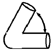
Fe (99.95%) ø0.5mm with 60-degree inclusive bend 12 1.2 458 358 1.3 
Mu Metal multistrand ø0.6mm 8.3 1.4 1118 128 8.7 
Mu Metal multistrand ø0.6mm 11.7 1.9 2475 180 13.7 
Mu Metal multistrand ø0.6mm 16.7 2.8 6539 229 28.5 
Mu Metal multistrand ø0.6mm in 0-degree inclusive angle (U-shape) 8.3 1.4 433 202 2.1 
Dumbbell-like: Ferritic stainless steel multi-strand: large ø1.5mm for 1mm, small ø0.91, overall length 5mm 3.3 4.6 1469 323 4.6 
Ball of yarn type: Metglass ø0.125mm, final dimensions loose ball of 2.5mm 41 1.0 1752 949 1.9 
Ball of yarn type: ferritic stainless steel (ø0.3 wire), final dimensions ball of 2mm × 3mm × 4mm 5.3 1338 787 1.7 
Ball of yarn type with collapsing plastic hinges: ferritic stainless steel (ø0.3 wire), overall dimensions ø1.5mm × 12mm 8 21.2 1086 750 1.5 
Ball of yarn type with collapsing hinges: ferritic stainless steel (ø0.3 wire), overall dimensions 1.5mm × 23 11.5 30.1 2030 1501 1.4 
String of columns 3-links: MnZn-Ferrite (ø1.5) 8 21.2 2327 1769 1.3 
String of columns 4-links: MnZn-Ferrite (ø1.5) 10.7 28.3 2707 2145 1.3 
Collapsing chain 5-links: Fe 99.95% (ø0.5 wire), overall dimensions 2mm × 10mm 5 31.4 1390 1086 1.3 
Spring in circle: Fe 99.95% (ø0.5 wire), overall dimensions 2mm × 20mm (coil width 2mm) 10 62.8 3990 3104 1.3 
Spring in circle: Fe 99.95% (ø0.5 wire), overall dimensions 2mm × 14mm (coil width 2mm) 7 44.0 3249 2305 1.4 
Spiral in circle: Ferritic Stainless Steel (ø0.3 single wire), overall dimensions 0.91mm × 15.7mm 17.4 10.8 772 251 3.1 
Spiral in circle: Ferritic Stainless Steel (2 × ø0.3 wire), overall dimensions 0.91mm × 15.7mm 17.4 10.8 1021 292 3.5 
Spiral in circle: Ferritic Stainless Steel (2 × ø0.3 wire), overall dimensions 0.91mm × 12.6 mm 14 8.7 785 261 3.0 
Interlocked U's: Ferritic stainless steel multi-strand overall dimensions 2mm × 7mm 3.5 15.9 5012 1060 4.7 
Single U of the interlocked U's Ferritic stainless steel mullti-strand, overall dimensions 2mm × 6.5mm 3.25 7.9 3253 644 5.1 
Interlocked U's: Ferritic stainless steel mullti-strand, overall dimensions 2mm × 5.5mm 2.75 12.2 3159 1045 3.0 
Interlocked U's: Fe (99.95%), overall dimensions 1.5mm × 4mm 2.7 2.4 723 185 3.9 
Tetrahedron from 2-columns: Fe (99.5%) each column ø1.0 × 3mm 9 4.7 858 678 1.3 
Tetrahedron from 2-columns: Ferritic stainless steel mullti-strand, each column ø0.9 × 5mm 11 6.6 1308 1129 1.2 
3 edges of tetrahedron inclusive angle 45-degrees out of plane between edges: Ferritic stainless steel (ø0.3) 40 0.8 342 231 1.5 
3 edges of tetrahedron inclusive angle 45-degrees out of plane between edges: Fe (99.5%) ø1.0mm 7 5.5 875 734 1.2 
3 edges of tetrahedron inclusive angle 45-degrees out of plane between edges: Fe (99.95%) ø0.5mm 36 3.5 1608 998 1.6 
3 edges of tetrahedron inclusive angle 45-degrees out of plane between edges: Fe (99.95%) ø0.5mm 30 2.9 1072 609 1.8 
Standard Marker Material: 316 stainless steel ø1.0mm 6 4.7 0 0 No response 
Standard Marker Material: Gold ø1.0mm 3 2.4 0 0 No response 
SecurMark® (Titanium) 0 0 No response 
RFID ø2.1mm × 12mm 5.7 41.6 4840 330 14.7 
RFID ø1.4mm × 8mm 5.3 12.3 1858 61 30.5 Anisotropy ratio for various shapes and sizes of magnetic marker at a constant distance -
Fig. 2(A) is a graph of the relative change in anisotropy ratio as the included angle of a bend in the marker is reduced. The measurements were taken using the test arrangement inFig. 2(B) . The graph (Fig. 2A ) shows that there is an optimum angle for a uniform signal when the angle is between 0° and 90°, and more preferably between 0° and 45°.Fig. 2(C) is a graph that shows how the signal varies with the angle of sensing relative to the marker's main axis for iron markers with different included angles.Fig. 2(D) is a graph that shows how the signal varies with the angle of sensing relative to the marker's main axis for iron markers with different included angles. - In some cases, it may be advantageous for the marker to assume the shape only after it has been deployed so that it can be packed more efficiently into the deployment needle prior to deployment. An elastic material or a section of elastic material may be used to facilitate this.
- Such shapes include, but are not limited to the following:
- "lozenge" or "bead" shapes (
Fig. 3(A) ), that reduce the anisotropy by providing more magnetic material in the transverse axis (perpendicular to the long axis of the bead). Such markers may include shaped ends comprising narrower sections that focus the field in a direction away from the main axis (Figs. 3(B) and (C) ). For example, a finite element model of the marker ofFig. 3(C) and a probe of the type described inUS Publication No. 2011/0133730 with the marker at a distance of 20 mm from the probe end gave an anisotropy ratio of magnetic susceptibility of 2.5; - "dumbbell-type" designs as shown in
Figs. 4 (A)-(D) , are constructed from segments of the same material. This design similarly provides more magnetic material along the transverse axis. In various embodiments, the markers being about 5-10 mm in length, and are useful in reducing the opposing eddy currents. For example, a finite element model of the marker of Fig. 4(E) and a probe of the type described inUS Publication No. 2011/0133730 with the marker at a distance of 20 mm from the probe end gave an anisotropy ratio of magnetic susceptibility of 2.6; - cable or multi-wire strands as shown in
Figs. 5(A) and (B) and may be twisted. A number of stranding forms are illustrated, but other stranding forms such as 1x4, 1x5 etc. with 3, 4, 5, 6, 7 or more strands are equally viable; using strands reduces the opposing eddy current loss and having multiple facets provides superior ultrasound response. The wires could also be hollow as illustrated or include void areas between the strands; - bent wires or tubes including acute and obtuse angles, U shapes, X shapes (Table 3);
- a single length of cylindrical marker divided into two or more small pieces of a similar size gives an improved anisotropy ratio of less than 5;
- a cylindrical marker with a larger diameter central section and smaller diameter outer sections also gives an improved anisotropy ratio;
- markers composed of two interlocked U shaped elements (
Fig. 18 ). - In one aspect of the invention, the implanted marker is made primarily from a magnetically soft material and the marker has a long thin aspect ratio prior to deployment but changes configuration after deployment to a shape with a low anisotropy of the magnetic susceptibility. Prior to deployment, the marker may have a length to diameter ratio or shape factor of greater than 5, and a ratio of magnetic anisotropy of susceptibility of greater than 5 or even greater than 7 or 9, such values resulting from the extended length of the marker prior to deployment and being beneficial to increase the volume of marker contained in the needle so as to maximize the magnetic response once deployed. After deployment, the ratio of magnetic anisotropy of susceptibility is less than 5 and preferably less than 3, and ideally 2 or less to provide a more uniform magnetic response.
- In one aspect, the marker is elastically deformable or resiliently deformable such that it elastically or resiliently changes in shape and size from a packed or pre-deployment shape within the needle or deployment device with an associated shape factor, to a post-deployment shape and shape factor. The elasticity or resilience may, for example, derive from the use of an elastic or resilient material or from an elastic, resilient or deployable structure or combinations thereof. Preferably, the magnetic marker is elastically or resiliently deformable between a packed configuration having a higher anisotropy of magnetic susceptibility, and a deployed / unpacked configuration having a lower anisotropy of magnetic susceptibility. Alternatively, the magnetic marker is elastically or resiliently deformable between a packed configuration having a higher projected area anisotropy ratio, and a deployed / unpacked configuration having a lower projected area anisotropy ratio.
- Preferably the deployed or delivered configuration of the marker has an anisotropy of magnetic susceptibility of less than 5, more preferably less than 3 and ideally less than 2 in order to give the most uniform detection signal; while prior to deployment within the delivery device, the marker in its packed configuration has an anisotropy of magnetic susceptibility of greater than 5 and more preferably greater than 7, in order to maximize the volume of material in the marker given the constrained diameter of the delivery device. By analogy, the marker in its packed configuration has a projected area anisotropy ratio of greater than 5 and more preferably greater than 7; but in a deployed / unpacked configuration has a projected area anisotropy ratio of less than 5, more preferably less than 3 and ideally less than 2. In order to achieve this configuration change, the marker requires a degree of resilience whereby one dimension (e.g., the diameter perpendicular to the main axis) of the marker changes by a factor of, at least, 1.5 times from its packed value to its deployed value. Preferably the deployed dimension is larger than the packed dimension by a factor of greater than 2 and more preferably greater than 3 in order to provide a shape factor (ratio of maximum dimension to minimum dimension) close to 1 or 2 on deployment, while still having sufficient material to be detected.
- The magnetic marker in its packed configuration is packed within a delivery device prior to use. The delivery device needs to be able to deliver the marker through the skin to mark the tissue area of interest, for example a cancerous lesion. Suitable delivery devices include any needle- or cannula-based delivery system, typically comprising a needle and means to propel the marker through the end or out of the side of the needle such as a plunger or stylet. The needle is preferably 14 to 18 gauge. This means that the needle has an internal diameter generally of 0.8mm to 1.5mm but may possibly be as large as 1.8mm for certain needle designs. Preferably it is between 1.0 and 1.5mm in diameter. If a vacuum-assisted needle is used, the needle size is typically 11 gauge, with an internal diameter of 2.3 to 2.5 mm.
- Markers that achieve the desired change in anisotropy of the magnetic susceptibility between their packed and unpacked configurations include, but are not limited to the following:
- "ball of yarn" type forms (
Figs. 6(A) and (B) ) that reduce the anisotropy by providing a substantially uniform amount of magnetic material in any given axis of the marker. The multiple facets provide also superior ultrasound response. A ball of yarn is preferably formed from a material with a large magnetic response such as a metallic glass or a magnetically soft material from the list above. The ball may be formed from a fine wire of diameter for example between 10µm and 250µm and length for example of between 5 mm and 150 mm, and bent into the shape of the ball. The marker may be elastically deformable or resiliently deformable. The marker is compressed to fit inside the deployment needle or delivery device, where, prior to delivery, it may be constrained to take a more cylindrical shape. On deployment the ball expands to close to its original size and takes a substantially spherical shape. Table 3 shows that this marker can achieve an anisotropy ratio of close to the ideal of 1. - "Chinese-lantern" forms (
Fig. 7 ). On deployment, this marker is arranged such that it resiliently reconfigures from a cylinder to a more compressed lantern configuration, thus increasing the uniformity of the magnetic response (reducing anisotropy) because the amount of material in the transverse axis is increased from that of a cylinder. The multiple facets also provide superior ultrasound response. - Markers comprising a plurality of magnetically soft elements joined with hinges as shown in
Fig. 8(A)-(G) that deform into shape on deployment (either plastically, pre-stressed or through the action of a shape-memory in the material). The greater length of the marker in this embodiment is possible because the shape of the marker in the deployment needle is linear but folds to another configuration upon injection into a site. This reduces the anisotropy by providing a substantially uniform amount of magnetic material in any given axis of the marker. - Advantageously, the multiple facets also provide superior ultrasound response. It is desirable to have at least 3 elements to obtain a uniform response, and many more may be added, although for complexity the number is preferably less than 20 and more preferably less than 10. The hinged and other flexible or resiliently deformable forms may comprise a plurality of smaller magnetic units or components joined by non-magnetic flexible or resiliently deformable links such as plastic or shape memory materials. Combinations of these forms, e.g., bent wire made from multi-strand cable, are also included. As shown in Table 3, a marker of this kind with multiple ball elements and a pre-deployment geometric length: diameter ratio of 8 can have a post-deployment magnetic anisotropy of susceptibility of less than 2.
- Markers comprising a plurality of elements joined with collapsible links between them such that on deployment the elements collapse together to form an amorphous region with a low ratio of magnetic anisotropy of susceptibility. The links can be formed from a string-like material such as suture or other polymer. Preferably, the magnetically soft elements are links in a chain that can collapse on itself after deployment.
- Markers comprising a springy or resiliently deformable wire, or cylindrical shape prior to deployment that on deployment forms a structure or wireframe. Such structures may include a cylindrical coil, helix, conical coil, spherical coil, random 'ball of yarn', or a polyhedron such as a tetrahedron or part thereof.
- Markers comprising a resiliently deformable looped or shaped coil spring that is compressed prior to deployment and expands upon deployment to a shape with a low ratio of magnetic anisotropy of susceptibility. For example, a coil spring shaped into a circle gives a surprisingly low ratio of magnetic anisotropy of susceptibility (Table 3). Preferably, the ratio of the circle diameter to the spring coil diameter is less than 5 in order to maintain a more uniform magnetic response.
- Markers comprising two or more elements connected by a link formed from an elastic or resiliently deformable or springy material such that the elements once deployed spring into a new configuration giving a low magnetic anisotropy of susceptibility. Table 4 illustrates one such embodiment comprising two short cylindrical elements formed of magnetically soft material joined by a spring filament. In the deployment needle, the two elements are constrained to be aligned axially joined by the filament. The filament is biased such that on deployment the two elements spring back across each other to approximate a tetrahedral shape with a low ratio of magnetic anisotropy of susceptibility of less than 2. The spring filament may be formed from a spring steel, shape memory material or other elastic or resiliently deformable material. Preferably, the length of the cylindrical elements is between 2 and 5 times their diameter to provide good uniformity of response combined with a compact shape. In a further embodiment of this concept, multiple elements on a springy material are deployed from the needle and the springy material is biased such that on deployment the elements are formed into a structure. Example structures may include a cylindrical coil, helix, conical coil, spherical coil, random 'ball of yarn', or a tetrahedron or part thereof. In these designs the length of the marker when in its packed configuration may be between 2 and 5 times their diameter but could be even greater e.g. up to 10 or more times the diameter depending on the degree of elasticity of the structure of material being used, thus allowing more magnetic material to be deployed to maximize the detectability of the marker.
- A further benefit of the "ball of yarn" (
Fig. 6 ) stranded or multi-facetted forms is superior visibility to such reflective imaging techniques as ultrasound, IR or ultra-wideband radar. These benefits can also be realised by revision of the external surface of the other forms mentioned, including the non-hinge sections of the hinged forms (Fig. 7 ) from cylindrical to facetted or grooved forms such as, but not limited to, triangular, pentagonal, dodecagon, cog-like cross sections (Fig. 9 ). A similar effect can be observed in ultrasound from sintered materials such as ferrites. Correct choice of soft material in any of the forms mentioned can provide visibility to X-ray imaging. Interlocked U's take similar space to U but with increased signal and reduced anisotropy (Fig. 18 ). - The above features can be combined to provide a marker with reduced anisotropy and improved imaging.
- In a further aspect of the invention, the ratio of magnetic anisotropy of susceptibility of the implanted marker is modified by varying the magnetic properties of the magnetically soft material forming the marker along its length.
- In another aspect of the invention, the reduction in magnetic anisotropy of susceptibility can be achieved through use of composite materials such as the formation of ferrite via sintering with two or more materials where at least one material is a soft material distributed to provide a less anisotropic response. Similar forms can be created, as previously mentioned, where multiple materials are used within the marker. One such embodiment is a single segmented marker with a constant cross section.
- An additional benefit of this aspect of the invention is that the soft distribution or shape can be independent of the external form and cross sections which improve imaging visibility under ultrasound or X-ray can be created. Further examples of composite magnetic markers with decreased anisotropy include soft markers distributed on a collapsible stent-like structure specifically those that are self-expanding.
- Additionally, in a cable or multi-wire strands (especially where twisted) embodiments include hollow versions where the individual wires are formed from different materials or formed from composite material, e.g., a core and a covering or sheath material where at least one or more of these are magnetically soft materials. A specific example of this is where the core or covering material is made from Nitinol or other shape memory material (including shape memory polymers) which is used to form the post deployment shape (
Fig. 10 ). It is equally possible to create wire where a core produced from multiple materials covered by the sheathing material is produced and either used directly as the magnetic marker or subsequently used in cable or multi-strand forms (Fig. 11 ). The wires or one of the segments multi-core wires could also be used to provide improved X-ray visibility. -
Figs. 12(A) and (B) are examples of segmented marker (note: more or fewer segments are possible). The segmentation increases losses between sections in the axial direction and manages the opposing eddy current effect, reducing the anisotropy. -
Figs 13(A) and (B) show examples of soft material (dark grey) that may be moulded into a shape that is independent of the external shape of the marker (note: more than two materials could be used within the construction). Anisotropy is improved by providing more magnetic material in the transverse axis and reducing the opposing eddy current through combination of the materials selected. In one embodiment shown inFig. 13(C) , the magnetically soft core is formed from a material with a very high magnetic response such as a metallic glass such that sufficient magnetic response can be obtained from only a very small sphere of the material. The core is encased in a protective layer comprising a biocompatible coating or capsule, for example a titanium shell or a biocompatible polymer coating. Because the core is spherical, the ratio of magnetic anisotropy of susceptibility is close to 1. - Shaped markers with hinges of plastic/pre-stressed/shape memory in multiple materials with different magnetic properties are shown in
Figs. 14 (A-E). These configurations improve the tailoring of the response in order to reduce the anisotropy by providing a substantially uniform response in any given axis of the marker. The multiple facets also provide superior ultrasound response. - In another aspect of the invention, a long thin marker is divided into a number of smaller markers. The multiple markers that are packed together prior to deployment have the same overall dimensions and material, and can be used to decrease the anisotropy relative to the overall dimensions of the material. For example, 3 × 2mm long or 2 × 3mm long or 6 × 1mm long marker pieces have decreased anisotropy in comparison to 1 × 6mm long marker of the same outer diameter. Surprisingly, this reduction in anisotropy occurs even when the segments align one behind each other in the same shape as an individual marker of the combined dimensions. (Table 5) For example, a single marker of dimension 5mm in ferritic stainless steel gives an anisotropy ratio of 6.7. Two markers of the 3mm markers in the same material give an anisotropy ratio of between 3.2 and 4.6 depending on relative orientations.
Table 5 Marker Pre-deployment dimensional ratio Volume (mm3) Signal Max Signal Min Anisotropy Ratio Relative Limit of detection Ferritic stainless steel multi-strand cable (0.91mm in diameter) 3.3 2.0 536 120 4.5 1.6 Ferritic stainless steel multi-strand cable (0.91mm in diameter) 4.4 2.5 939 143 6.6 1.7 Ferritic stainless steel multi-strand cable (0.91mm in diameter) 5.5 3.2 1212 182 6.7 2.0 Two (2) Ferritic stainless steel multi-strand cable various configurations 6.6 3.9 810-1091 240-254 3.2-4.6 1.7-1.9 - In a further specific example of this, a set of markers or magnetic particles produced from magnetically soft material can retain a small amount of magnetism. Once deployed into the patient, these magnetic particles can then self-assemble into an associated magnetic marker which possesses lower magnetic anisotropy of susceptibility. Multiple magnetically soft markers with a small magnetic remanence will self-assemble into an associated magnetic marker with a substantially uniform amount of material in every direction, thereby minimising anisotropy (
Fig. 15 ). This small magnetic remanence can be overcome by the magnetic excitation of the exciting field of the magnetometer (or susceptometer) as described above. Table 6 shows the parameters of particles assembled by two types of magnetic compositions.Table 6 Marker Pre-deployment dimensional ratio Volume (mm3) Signal Max Signal Min Anisotropy Ratio MnZn-Ferrite (1.0mm in diameter) 3.5 5.9 981 166 5.9 MnZn-Ferrite (0.75mm in diameter) 10 3.3 4120 202 20.4 Assembly of small markers as per Fig. 15 (0.75mm in diameter MnZn-Ferrite)8.7 2.9 583 448 1.3 - In a further example of this, magnetically soft markers or particles encased within hydrophobic surfaces (nano-texturing via lotus effect, silica nano-coatings, EnBio CoBlast PTFE, Hydroxyapitite, carbon nanotube coatings, precipitate calcium carbide & fatty acid coating with polymer latex, manganese oxide polystyrene or zinc oxide polystyrene nano-composites) or spheres will pull together (self-assemble) on deployment into the patient. To minimise surface energy, this embodiment will form a close-packed shape such as a sphere or ellipsoid system which will have an improved magnetic anisotropy of susceptibility relative to the particles within the delivery system which will constrain in an elongated shape to be elongated.
Fig. 16 depicts hydrophobic coated markers or particles which self-assemble, to minimise surface energy, into an associated magnetic marker with a substantially uniform amount of material in every direction minimising anisotropy. - In another aspect of the invention, small micromarkers or microparticles of a soft material can be suspended within a biocompatible matrix (
Figs. 17(A) and (B) ). Control of the magnetic particle distribution, in a similar manner as discussed with respect toFigs. 10-12 , allows a decreased magnetic anisotropy of susceptibility as well as the independence from the outer form. It can also be used to ensure a set location and orientation between the magnetic markers. - In a further example of this for the case, by using a gel matrix with a suspension of magnetically soft particles and by sizing these particles appropriately, the gel and particles can be deployed through the deployment needle (
Fig. 17(B) ). The shape of the deployed gel and particles will be constrained only by the injection site (i.e. the tissue of a lesion) which is less in comparison to that of the needle. This gel can also set on injection making it less likely to migrate from its deployed location and easier to remove surgically if the tissue is being removed. The addition of other particles such as gold to provide additional radiopaque response for x-ray visualisation could be performed if required. For marker localization, the anisotropy should be less than or equal to 9, preferably less than or equal to 6, more preferably less than or equal to 3. - The present invention provides various ways of making magnetic markers with acceptable anisotropy while not affecting the ease of delivery of the particles.
- In another aspect of the invention, a method is provided for marking a soft tissue site of interest, such as the site of a tumor or benign lesion for example within the breast, lung, bowel/colon, rectum, prostate or other cancer affected organ, or a lymph node within the axilla or other nodal basin within the body. The method includes the steps of (i) inserting such a magnetic marker into tissue near the target lesion or site, and (ii) detecting such a marker using a susceptometer, and optionally (iii) surgically excising the target tissue around the marker. Preferably, the susceptometer detects the marker by providing a magnetic field in the region of the marker and measuring the induced magnetization in the marker.
- Unless otherwise indicated, all numbers expressing lengths, widths, depths, or other dimensions, and so forth used in the specification and claims are to be understood in all instances as indicating both the exact values as shown and as being modified by the term "about." Accordingly, unless indicated to the contrary, the numerical parameters set forth in the specification and attached claims are approximations that may vary depending upon the desired properties sought to be obtained. At the very least, and not as an attempt to limit the application of the doctrine of equivalents to the scope of the claims, each numerical parameter should at least be construed in light of the number of reported significant digits and by applying ordinary rounding techniques. Any specific value may vary by 20%.
- The terms "a," "an," "the," and similar referents used in the context of describing the invention (especially in the context of the following claims) are to be construed to cover both the singular and the plural, unless otherwise indicated herein or clearly contradicted by context. All methods described herein can be performed in any suitable order unless otherwise indicated herein or otherwise clearly contradicted by context. The use of any and all examples, or exemplary language (e.g., "such as") provided herein is intended merely to better illuminate the invention and does not pose a limitation on the scope of any claim. No language in the specification should be construed as indicating any non-claimed element essential to the practice of the invention.
- Groupings of alternative elements or embodiments disclosed herein are not to be construed as limitations. Each group member may be referred to and claimed individually or in any combination with other members of the group or other elements found herein. It is anticipated that one or more members of a group may be included in, or deleted from, a group for reasons of convenience and/or patentability. When any such inclusion or deletion occurs, the specification is deemed to contain the group as modified thus fulfilling the written description of all Markush groups used in the appended claims.
- Certain embodiments are described herein, including the best mode known to the inventor for carrying out the spirit of the present disclosure. Of course, variations on these described embodiments will become apparent to those of ordinary skill in the art upon reading the foregoing description. The inventor expects skilled artisans to employ such variations as appropriate, and the inventor intends for the invention to be practiced otherwise than specifically described herein. Accordingly, the claims include all modifications and equivalents of the subject matter recited in the claims as permitted by applicable law. Moreover, any combination of the above-described elements in all possible variations thereof is contemplated unless otherwise indicated herein or otherwise clearly contradicted by context.
- In closing, it is to be understood that the embodiments disclosed herein are illustrative of the principles of the claims. Other modifications that may be employed are within the scope of the claims. Thus, by way of example, but not of limitation, alternative embodiments may be utilized in accordance with the teachings herein. Accordingly, the claims are not limited to embodiments precisely as shown and described.
-
- 1. A packed magnetic marker held within a delivery device for marking a site in tissue in the body comprising a non-spherical configuration prior to deployment having a ratio of maximum magnetic response to minimum magnetic response (ratio of magnetic anisotropy of susceptibility) after deployment of less than 5.
- 2. The magnetic marker of
paragraph 1 wherein the aspect ratio (length to diameter) of the marker before deployment is greater than 4. - 3. The magnetic marker of
paragraph 1 wherein the ratio of magnetic anisotropy of susceptibility of the marker before deployment is greater than 5. - 4. The magnetic marker of
paragraph 1 wherein the marker is resiliently deformable between a packed configuration having a higher magnetic anisotropy of susceptibility, and a deployed / unpacked configuration having a lower magnetic anisotropy of susceptibility. - 5. The magnetic marker of
paragraph 1 wherein the marker is resiliently deformable between a packed configuration having a higher projected area anisotropy ratio, and a deployed / unpacked configuration having a lower projected area anisotropy ratio. - 6. The magnetic marker of
paragraph 1 wherein the non-spherical configuration is of the shape selected from the group comprising a cylinder, a cable, a bead, a "dumbbell-like" form, and a ball of yarn. - 7. The magnetic marker of
paragraph 6 wherein the cylinder or cable bends upon placement in tissue. - 8. The magnetic marker of
paragraph 1 wherein the non-spherical configuration has an anisotropy ratio less than 6. - 9. The magnetic marker of
paragraph 1 wherein the non-spherical configuration has a ratio of magnetic anisotropy of susceptibility less than 3. - 10. The magnetic marker of
paragraph 1 wherein the non-spherical configuration is faceted. - 11. The magnetic marker of
paragraph 1 comprising one or more magnetic material(s), the magnetic materials having magnetic mass susceptibility preferably >0.05 , more preferably Al and even more preferably >5 m3kg 1 - 12. The magnetic marker of
paragraph 1 comprising one or more magnetic material(s), the magnetic materials having a coercivity of less than 100 Oe. - 13. A magnetic marker for marking a site in tissue in the body comprising: a plurality of magnetic components linked by flexible non-magnetic components that reconfigures upon placement in the site.
- 14. A magnetic marker for marking a site in tissue in the body comprising: a magnetic component made of one or more materials of a first shape located within a non-magnetic matrix of a second shape.
- 15. A magnetic marker for marking a site in tissue in the body comprising: a magnetic material core within a magnetic material sheath.
- 16. The magnetic marker of paragraph 15 wherein one of the core and the sheath comprises a magnetically soft material with coercivity of less than 100 Oe.
- 17. A magnetic marker for marking a site in tissue in the body comprising: a plurality of magnetic components which self-assemble into the magnetic marker following placement of the markers into the body.
- 18. The magnetic marker of paragraph 17 where the magnetic components are each encased within a hydrophobic coating.
- 19. A magnetic marker for marking a site in tissue in the body comprising a magnetic metallic glass.
Claims (13)
- A deployable magnetic marker for marking a site in tissue; the magnetic marker being formed of a solid, magnetically soft material having a magnetic coercivity of less than or equal to 79.6 kAm-1 (1000 Oe) and a magnetic mass susceptibility of at least 0.05 m3 kg-1; wherein the magnetic marker comprises a multi-stranded cable having a ratio of anisotropy of magnetic susceptibility of less than 9 when deployed.
- A deployable magnetic marker as claimed in claim 1, wherein the multi-stranded cable comprises 3, 4, 5, 6, 7 or more strands of wire.
- A deployable magnetic marker as claimed in claim 1 or claim 2, wherein the multi-stranded cable is twisted.
- A deployable magnetic marker as claimed in claim 1, claim 2 or claim 3, wherein the strands are hollow or include void areas between the wire strands.
- A deployable magnetic marker as claimed in any preceding claim, wherein the marker has a diameter of 0.8-1.8 mm prior to deployment.
- A deployable magnetic marker as claimed in any preceding claims, wherein the magnetic marker has a ratio of anisotropy of magnetic susceptibility of less than 5.
- A deployable magnetic marker of claim 6, wherein the magnetic marker has a ratio of anisotropy of magnetic susceptibility of less than 3.
- The magnetic marker of any one of the preceding claims wherein the magnetic material has a magnetic coercivity of less than 7.96 kAm-1 (100 Oe).
- The magnetic marker of claim 8 wherein the magnetic material has a magnetic coercivity of less than 3.98 kAm-1 (50 Oe).
- The magnetic marker of any preceding claim, wherein the magnetically soft material is a paramagnetic, ferromagnetic or ferrimagnetic material.
- The magnetic marker of any preceding claim, wherein the magnetically soft material selected from iron, nickel, cobalt and their alloys, electrical iron, silicon-irons, iron-phosphorous, nickel-iron, Heusler alloys, Femico alloys (iron-nickel-cobalt based alloys), Cunife alloys (copper-nickel-iron based alloys), Alcomax alloys (iron-nickel-aluminium-cobalt-copper based alloys), stainless steels from the 300 series, 400 series and stainless steel alloys (e.g. chrome-iron alloys, martensitic stainless steels), ferrites such as MnZn-ferrites, NiZn-ferrites, MgZn-ferrites, Ba-ferrites, MnMgZn-ferrites, and MgZnCu-ferrites; amorphous metal or bulk metallic glass, magnetic carbon allotropes (e.g. fullerenes, highly oriented pyrolytic graphite, carbon nanofoams, nano-porous carbon).
- The magnetic marker of any preceding claim, wherein the magnetically soft material is coated with or contained within a biocompatible material.
- The magnetic marker of claim 12, wherein the biocompatible material is selected from bioglass, diamond-like-carbon (DLC), gold, hydroxyapatite, iron, magnesium, nitinol, parylene, phosphorylcholine (PC) polymer, poly-butyl methacrylate (PMBA) and polyethylenevinyl acetate (PEVA), polyethylene, PET, polytetraflouroethyleene (PTFE), PEBAX, PEEK, PEKK, platinum, silicone and titanium.
Applications Claiming Priority (4)
| Application Number | Priority Date | Filing Date | Title |
|---|---|---|---|
| US201562170768P | 2015-06-04 | 2015-06-04 | |
| EP16728722.6A EP3302338B1 (en) | 2015-06-04 | 2016-06-03 | Marker materials and forms for magnetic marker localization |
| PCT/GB2016/051649 WO2016193753A2 (en) | 2015-06-04 | 2016-06-03 | Marker materials and forms for magnetic marker localization (mml) |
| EP20180295.6A EP3782575A1 (en) | 2015-06-04 | 2016-06-03 | Marker materials and forms for magnetic marker localization (mml) |
Related Parent Applications (2)
| Application Number | Title | Priority Date | Filing Date |
|---|---|---|---|
| EP20180295.6A Division EP3782575A1 (en) | 2015-06-04 | 2016-06-03 | Marker materials and forms for magnetic marker localization (mml) |
| EP16728722.6A Division EP3302338B1 (en) | 2015-06-04 | 2016-06-03 | Marker materials and forms for magnetic marker localization |
Publications (2)
| Publication Number | Publication Date |
|---|---|
| EP4085866A2 true EP4085866A2 (en) | 2022-11-09 |
| EP4085866A3 EP4085866A3 (en) | 2023-01-18 |
Family
ID=56119700
Family Applications (3)
| Application Number | Title | Priority Date | Filing Date |
|---|---|---|---|
| EP16728722.6A Active EP3302338B1 (en) | 2015-06-04 | 2016-06-03 | Marker materials and forms for magnetic marker localization |
| EP22176363.4A Pending EP4085866A3 (en) | 2015-06-04 | 2016-06-03 | Marker materials and forms for magnetic marker localization |
| EP20180295.6A Pending EP3782575A1 (en) | 2015-06-04 | 2016-06-03 | Marker materials and forms for magnetic marker localization (mml) |
Family Applications Before (1)
| Application Number | Title | Priority Date | Filing Date |
|---|---|---|---|
| EP16728722.6A Active EP3302338B1 (en) | 2015-06-04 | 2016-06-03 | Marker materials and forms for magnetic marker localization |
Family Applications After (1)
| Application Number | Title | Priority Date | Filing Date |
|---|---|---|---|
| EP20180295.6A Pending EP3782575A1 (en) | 2015-06-04 | 2016-06-03 | Marker materials and forms for magnetic marker localization (mml) |
Country Status (10)
| Country | Link |
|---|---|
| US (4) | US10595957B2 (en) |
| EP (3) | EP3302338B1 (en) |
| JP (1) | JP6821665B2 (en) |
| KR (1) | KR102589814B1 (en) |
| CN (2) | CN113558782B (en) |
| AU (1) | AU2016272550B2 (en) |
| CA (1) | CA2988065C (en) |
| ES (1) | ES2833377T3 (en) |
| MX (1) | MX390935B (en) |
| WO (1) | WO2016193753A2 (en) |
Families Citing this family (23)
| Publication number | Priority date | Publication date | Assignee | Title |
|---|---|---|---|---|
| US9936892B1 (en) | 2009-05-04 | 2018-04-10 | Cortex Manufacturing Inc. | Systems and methods for providing a fiducial marker |
| WO2014081940A1 (en) | 2012-11-21 | 2014-05-30 | Trustees Of Boston University | Tissue markers and uses thereof |
| US20180140869A1 (en) * | 2015-06-04 | 2018-05-24 | Koninklijke Philips N.V. | Determination of positions of objects, such as brachytherapy seeds |
| CN105852984B (en) * | 2016-03-23 | 2020-02-18 | 堃博生物科技(上海)有限公司 | Lung marker |
| EP4461216A3 (en) * | 2016-09-09 | 2025-02-12 | Stryker Corporation | System for magnetic occult lesion localization and imaging |
| GB2582123B (en) | 2018-01-25 | 2021-04-28 | Endomagnetics Ltd | Systems and methods for detecting magnetic markers for surgical guidance |
| GB2573500B (en) | 2018-03-23 | 2020-11-04 | Endomagnetics Ltd | Magnetic markers for surgical guidance |
| WO2020077207A1 (en) | 2018-10-12 | 2020-04-16 | Focal Therapeutics Inc. | Tissue localization device and method of use thereof |
| US11266481B2 (en) | 2018-10-12 | 2022-03-08 | Hologic, Inc. | Tissue localization marker with D-shaped cross-section |
| WO2020154934A1 (en) * | 2019-01-30 | 2020-08-06 | 唐山哈船科技有限公司 | Operation assistant locator |
| KR102251651B1 (en) * | 2019-03-19 | 2021-05-14 | 오스템임플란트 주식회사 | Method for generating curve line automatically for panoramic image generation and dental image processing apparatus for the same |
| PL3946135T3 (en) * | 2019-05-30 | 2024-05-20 | Devicor Medical Products, Inc. | Biopsy site marker for limited migration |
| GB2585034A (en) * | 2019-06-25 | 2020-12-30 | Endomagnetics Ltd | Hyperthermia implants and a method and system for heating the implant |
| WO2021005955A1 (en) * | 2019-07-10 | 2021-01-14 | 京都府公立大学法人 | Medical image guidance marker |
| US20230329832A1 (en) * | 2019-10-23 | 2023-10-19 | Clemson University | A Breast Tissue Marker and Localization System |
| US11166782B1 (en) | 2020-07-19 | 2021-11-09 | Sirius Medical Systems B.V. | Implantable marker and a method of implanting markers |
| JP2023545354A (en) * | 2020-10-07 | 2023-10-30 | カムトムサム・アクチボラグ | Alignment marker that serves as a reference for radiotherapy |
| JP7541784B2 (en) * | 2021-07-30 | 2024-08-29 | 株式会社 マトリックス細胞研究所 | Magnetic Marker Set |
| GB2612598B8 (en) * | 2021-11-03 | 2025-02-12 | Endomagnetics Ltd | Magnetic markers for imaging and surgical guidance |
| GB2612597B8 (en) * | 2021-11-03 | 2025-02-12 | Endomagnetics Ltd | Improvements in or relating to implantable ferromagnetic markers |
| EP4475930A1 (en) * | 2022-02-07 | 2024-12-18 | Anttila, Eric, D. | Medical systems, devices, and kits useful in performing treatment under magnetic resonance imaging and related methods |
| GB2617357B (en) | 2022-04-05 | 2024-09-11 | Endomagnetics Ltd | Improvements in or relating to susceptibility probes for detecting surgical markers |
| GB2620722B (en) | 2022-04-05 | 2024-12-04 | Endomagnetics Ltd | Improvements in or relating to susceptibility probes for detecting surgical markers |
Citations (5)
| Publication number | Priority date | Publication date | Assignee | Title |
|---|---|---|---|---|
| US3492566A (en) | 1967-09-01 | 1970-01-27 | Canadian Patents Dev | Three dimensional magnetic anisotropic susceptibility meter |
| US6173715B1 (en) | 1999-03-01 | 2001-01-16 | Lucent Medical Systems, Inc. | Magnetic anatomical marker and method of use |
| US20110133730A1 (en) | 2009-12-04 | 2011-06-09 | Simon Richard Hattersley | Magnetic Probe Apparatus |
| WO2014013235A1 (en) | 2012-07-16 | 2014-01-23 | Endomagnetics Ltd | Magnetic marker for surgical localization |
| US20140314679A1 (en) | 2013-03-11 | 2014-10-23 | Endomagnetics Ltd. | Hypoosmotic Solutions for Lymph Node Detection |
Family Cites Families (175)
| Publication number | Priority date | Publication date | Assignee | Title |
|---|---|---|---|---|
| US2614164A (en) | 1947-11-12 | 1952-10-14 | Schlumberger Well Surv Corp | Mutual inductance system |
| US3449662A (en) | 1963-10-16 | 1969-06-10 | American Mach & Foundry | Magnetic inspection method and apparatus using resilient magnetizing means and resilient sensors |
| US3445928A (en) | 1966-03-25 | 1969-05-27 | Bunker Ramo | Magnetometer method of manufacture |
| US4324255A (en) | 1980-03-07 | 1982-04-13 | Barach John P | Method and apparatus for measuring magnetic fields and electrical currents in biological and other systems |
| GB2109112A (en) | 1981-10-06 | 1983-05-25 | Pantatron Systems Limited | Eddy current test probe |
| JPH0768117B2 (en) | 1983-05-06 | 1995-07-26 | ベスター・インコーポレイテツド | Vesicle formulation for controlled drug release |
| US4823113A (en) * | 1986-02-27 | 1989-04-18 | Allied-Signal Inc. | Glassy alloy identification marker |
| US5055288A (en) | 1987-06-26 | 1991-10-08 | Advanced Magnetics, Inc. | Vascular magnetic imaging method and agent comprising biodegradeable superparamagnetic metal oxides |
| US5261403A (en) | 1987-03-30 | 1993-11-16 | Hitachi, Ltd. | Magnetic resonance imaging apparatus |
| US5414356A (en) | 1987-09-21 | 1995-05-09 | Hitachi, Ltd. | Fluxmeter including squid and pickup coil with flux guiding core and method for sensing degree of deterioration of an object |
| US4825162A (en) | 1987-12-07 | 1989-04-25 | General Electric Company | Nuclear magnetic resonance (NMR) imaging with multiple surface coils |
| JP2613275B2 (en) | 1988-09-16 | 1997-05-21 | 株式会社日立製作所 | Fluxmeter using superconducting quantum interference device |
| EP0390935A1 (en) | 1989-03-29 | 1990-10-10 | Siemens Aktiengesellschaft | Calibration method for multichannel squid systems with gradiometers in any order |
| US5442289A (en) | 1989-07-31 | 1995-08-15 | Biomagnetic Technologies, Inc. | Biomagnetometer having flexible sensor |
| DE4003330A1 (en) | 1990-02-05 | 1991-08-08 | Foerster Inst Dr Friedrich | Eddy current tester |
| US5005001A (en) | 1990-04-05 | 1991-04-02 | Pitney Bowes Inc. | Field generation and reception system for electronic article surveillance |
| US5512821A (en) | 1991-06-04 | 1996-04-30 | Nkk Corporation | Method and apparatus for magnetically detecting defects in an object with compensation for magnetic field shift by means of a compensating coil |
| US5293119A (en) | 1992-02-20 | 1994-03-08 | Sqm Technology, Inc. | Electromagnetic microscope for evaluation of electrically conductive and magnetic materials |
| JP2882167B2 (en) | 1992-03-06 | 1999-04-12 | ダイキン工業株式会社 | SQUID magnetometer |
| FR2689638B1 (en) | 1992-04-06 | 1996-08-09 | Aerospatiale | EDDY CURRENT SENSOR. |
| US5313192A (en) * | 1992-07-02 | 1994-05-17 | Sensormatic Electronics Corp. | Deactivatable/reactivatable magnetic marker having a step change in magnetic flux |
| JP3337075B2 (en) | 1992-08-05 | 2002-10-21 | 名糖産業株式会社 | Small particle size water-soluble carboxy polysaccharide-magnetic iron oxide complex |
| DE4226814A1 (en) | 1992-08-13 | 1994-02-17 | Philips Patentverwaltung | Coil arrangement for MR examinations of the breast |
| US6023165A (en) | 1992-09-28 | 2000-02-08 | Fonar Corporation | Nuclear magnetic resonance apparatus and methods of use and facilities for incorporating the same |
| US5575794A (en) | 1993-02-12 | 1996-11-19 | Walus; Richard L. | Tool for implanting a fiducial marker |
| JPH06324021A (en) | 1993-03-16 | 1994-11-25 | Hitachi Ltd | Non-destructive inspection device |
| US5537037A (en) | 1993-03-16 | 1996-07-16 | Hitachi, Ltd. | Apparatus with cancel coil assembly for cancelling a field parallel to an axial direction to the plural coils and to a squid pick up coil |
| DE69433588T2 (en) | 1993-04-26 | 2005-02-03 | St. Louis University | DISPLAY OF THE POSITION OF A PROBE |
| US5590654A (en) | 1993-06-07 | 1997-01-07 | Prince; Martin R. | Method and apparatus for magnetic resonance imaging of arteries using a magnetic resonance contrast agent |
| US5363845A (en) | 1993-08-13 | 1994-11-15 | Medical Advances, Inc. | Breast coil for magnetic resonance imaging |
| BE1007459A3 (en) | 1993-08-24 | 1995-07-04 | Philips Electronics Nv | A magnetic resonance apparatus. |
| US5437280A (en) | 1993-09-20 | 1995-08-01 | Hussman; Karl L. | Magnetic resonance breast localizer |
| JPH0815229A (en) | 1994-06-27 | 1996-01-19 | Mitsubishi Heavy Ind Ltd | High resolution eddy current flaw detector |
| US5402094A (en) | 1994-08-15 | 1995-03-28 | Enge; Harald A. | MRI mammography magnet |
| EP0781114B1 (en) | 1994-09-16 | 2005-05-25 | Ethicon Endo-Surgery, Inc. | Devices for defining and marking tissue |
| DE19503664C2 (en) * | 1995-01-27 | 1998-04-02 | Schering Ag | Magnetorelaxometric detection of analytes |
| JP3910222B2 (en) | 1995-03-10 | 2007-04-25 | 株式会社豊田中央研究所 | Fatigue measuring device |
| US5657756A (en) | 1995-06-07 | 1997-08-19 | Ctf Systems Inc. | Method and systems for obtaining higher order gradiometer measurements with lower order gradiometers |
| JP3580905B2 (en) | 1995-06-13 | 2004-10-27 | 大日本印刷株式会社 | Magnetic sensor |
| JP3499054B2 (en) | 1995-07-11 | 2004-02-23 | 独立行政法人 国立印刷局 | Authenticity determination device for safety paper |
| US5842986A (en) | 1995-08-16 | 1998-12-01 | Proton Sciences Corp. | Ferromagnetic foreign body screening method and apparatus |
| DE19532676C1 (en) | 1995-09-05 | 1997-05-07 | Inst Physikalische Hochtech Ev | Arrangement for determining the position of a marker in a cavity within the organism of a living being |
| CZ234898A3 (en) | 1996-01-25 | 1998-11-11 | Schering Aktiengesellschaft | Improved concentrated injection and infusion solutions for intravasal use |
| EP0902687A1 (en) | 1996-03-11 | 1999-03-24 | Focal, Inc. | Polymeric delivery of radionuclides and radiopharmaceuticals |
| JPH1038854A (en) | 1996-07-17 | 1998-02-13 | Agency Of Ind Science & Technol | Non-destructive inspection method and apparatus for conductive material |
| EP1284123B1 (en) | 1996-08-12 | 2005-07-20 | Ethicon Endo-Surgery, Inc. | Apparatus for marking tissue |
| EP0919002A1 (en) | 1996-08-16 | 1999-06-02 | Jon Neal Weaver | Anti-shoplifting security system |
| US5844140A (en) | 1996-08-27 | 1998-12-01 | Seale; Joseph B. | Ultrasound beam alignment servo |
| US5997473A (en) | 1996-09-06 | 1999-12-07 | Olympus Optical Co., Ltd. | Method of locating a coil which consists of determining the space occupied by a source coil generating a magnetic field |
| DE29724862U1 (en) | 1996-09-18 | 2004-12-30 | Ifm Electronic Gmbh | Inductive proximity switch for electrical and electronic switching, measurement and control circuit - has two transmission coils arranged one after other in direction of influence, with receiver coils connected to evaluation circuit and mounted centrally between transmitter coils |
| US6304075B1 (en) | 1996-12-27 | 2001-10-16 | Bic-Niesse GmbH —Business and Innovation Centre in der Euroregion Neisse | Magnetic resonance sensor |
| US6406420B1 (en) | 1997-01-02 | 2002-06-18 | Myocor, Inc. | Methods and devices for improving cardiac function in hearts |
| AU2869900A (en) | 1997-02-27 | 2000-08-25 | Uri Rapoport | Method and apparatus for detecting a magnetically responsive substance |
| GB9712524D0 (en) | 1997-06-16 | 1997-08-20 | Nycomed Imaging As | Method |
| FR2770779B1 (en) | 1997-11-10 | 2000-07-21 | Bernstein Veronique | HYPOTONIC OR HYPOOSMOLAR PLASMA SOLUTE FOR THE TREATMENT OF CELLULITE, FIBROSIS, AND HIRSUTISM |
| US6270464B1 (en) | 1998-06-22 | 2001-08-07 | Artemis Medical, Inc. | Biopsy localization method and device |
| US6205352B1 (en) | 1997-11-19 | 2001-03-20 | Oncology Innovations, Inc. | Sentinel node identification using non-isotope means |
| CA2260703A1 (en) * | 1998-04-07 | 1999-10-07 | Dennis W. Szymaitis | Disposal container for detecting, distinguishing and counting objects |
| US6161034A (en) | 1999-02-02 | 2000-12-12 | Senorx, Inc. | Methods and chemical preparations for time-limited marking of biopsy sites |
| US6347241B2 (en) | 1999-02-02 | 2002-02-12 | Senorx, Inc. | Ultrasonic and x-ray detectable biopsy site marker and apparatus for applying it |
| AU2001217746A1 (en) | 1998-05-14 | 2002-05-27 | Calypso Medical, Inc. | Systems and methods for locating and defining a target location within a human body |
| US5941890A (en) | 1998-06-26 | 1999-08-24 | Ethicon Endo-Surgery, Inc. | Implantable surgical marker |
| EP1052658B1 (en) * | 1998-11-26 | 2014-03-12 | Hitachi Metals, Ltd. | Ferrite magnet powder and magnet using said magnet powder, and method for preparing them |
| US6356782B1 (en) | 1998-12-24 | 2002-03-12 | Vivant Medical, Inc. | Subcutaneous cavity marking device and method |
| US6371904B1 (en) | 1998-12-24 | 2002-04-16 | Vivant Medical, Inc. | Subcutaneous cavity marking device and method |
| US6230038B1 (en) | 1999-02-01 | 2001-05-08 | International Business Machines Corporation | Imaging of internal structures of living bodies by sensing implanted magnetic devices |
| US6725083B1 (en) | 1999-02-02 | 2004-04-20 | Senorx, Inc. | Tissue site markers for in VIVO imaging |
| US7983734B2 (en) | 2003-05-23 | 2011-07-19 | Senorx, Inc. | Fibrous marker and intracorporeal delivery thereof |
| US6862470B2 (en) | 1999-02-02 | 2005-03-01 | Senorx, Inc. | Cavity-filling biopsy site markers |
| GB9908179D0 (en) * | 1999-04-09 | 1999-06-02 | Univ Cambridge Tech | Magnetic materials |
| WO2000062672A1 (en) | 1999-04-15 | 2000-10-26 | Surgi-Vision | Methods for in vivo magnetic resonance imaging |
| EP2025350A3 (en) | 1999-04-21 | 2009-12-09 | The Government of the United States of America as represented by the Secretary of the Department of Health and Human Services | Determining pH by CEDST MRI |
| US6292678B1 (en) * | 1999-05-13 | 2001-09-18 | Stereotaxis, Inc. | Method of magnetically navigating medical devices with magnetic fields and gradients, and medical devices adapted therefor |
| US6766186B1 (en) | 1999-06-16 | 2004-07-20 | C. R. Bard, Inc. | Post biospy tissue marker and method of use |
| JP2001000430A (en) | 1999-06-24 | 2001-01-09 | Alcare Co Ltd | Marker for image photographing |
| WO2001008578A1 (en) * | 1999-07-30 | 2001-02-08 | Vivant Medical, Inc. | Device and method for safe location and marking of a cavity and sentinel lymph nodes |
| US6835572B1 (en) | 1999-10-18 | 2004-12-28 | Institute For Magnetic Resonance Research | Magnetic resonance spectroscopy of breast biopsy to determine pathology, vascularization and nodal involvement |
| JP2001255358A (en) | 2000-03-10 | 2001-09-21 | Sumitomo Electric Ind Ltd | Magnetic sensor |
| AU2001251348A1 (en) | 2000-04-07 | 2001-10-23 | The Johns-Hopkins University | Apparatus for sensing human prostate tumor |
| US6889073B2 (en) | 2000-05-08 | 2005-05-03 | David A. Lampman | Breast biopsy and therapy system for magnetic resonance imagers |
| JP2002004118A (en) * | 2000-06-21 | 2002-01-09 | Unitika Ltd | Garment for poriomania patient |
| US6544269B2 (en) | 2000-08-10 | 2003-04-08 | Cook Incorporated | Localizer needle |
| US6394965B1 (en) | 2000-08-15 | 2002-05-28 | Carbon Medical Technologies, Inc. | Tissue marking using biocompatible microparticles |
| JP2006500115A (en) | 2000-11-16 | 2006-01-05 | マイクロスフエリツクス・エル・エル・シー | Flexible and / or elastic seeds or strands for brachytherapy |
| ES2409758T3 (en) | 2000-11-20 | 2013-06-27 | Senorx, Inc. | Tissue site markers for in vivo imaging |
| FR2823092B1 (en) | 2001-04-10 | 2004-03-05 | Eurorad 2 6 | PER-OPERATIVE DEVICE FOR LOCATING MARKED TISSUES AND METHOD USING SUCH A DEVICE |
| WO2002082979A2 (en) * | 2001-04-18 | 2002-10-24 | Bbms Ltd. | Navigating and maneuvering of an in vivo vechicle by extracorporeal devices |
| JP4193382B2 (en) | 2001-07-19 | 2008-12-10 | 株式会社日立製作所 | Magnetic field measuring device |
| US6850065B1 (en) | 2001-07-27 | 2005-02-01 | General Electric Company | MRI coil system for breast imaging |
| US6592608B2 (en) | 2001-12-07 | 2003-07-15 | Biopsy Sciences, Llc | Bioabsorbable sealant |
| ITSV20010029A1 (en) | 2001-08-14 | 2003-02-14 | Esaote Spa | NUCLEAR MAGNETIC RESONANCE IMAGE DETECTION MRI (MRI) |
| US20030141868A1 (en) | 2001-08-23 | 2003-07-31 | Bakharev Alexander A. | High balance gradiometer |
| US7135978B2 (en) | 2001-09-14 | 2006-11-14 | Calypso Medical Technologies, Inc. | Miniature resonating marker assembly |
| US7701209B1 (en) | 2001-10-05 | 2010-04-20 | Fonar Corporation | Coils for horizontal field magnetic resonance imaging |
| JP4090722B2 (en) | 2001-10-23 | 2008-05-28 | 純一 小川 | Magnetic fluid detection device |
| US20030216632A1 (en) | 2001-10-29 | 2003-11-20 | Mednovus, Inc. | Ferromagnetic sensing method and apparatus |
| JP2003149212A (en) | 2001-11-09 | 2003-05-21 | Japan Science & Technology Corp | Non-destructive inspection equipment |
| AU2002357056A1 (en) | 2001-12-03 | 2003-06-17 | Philip M. Anderson Iii | Portable surgical implement detector |
| IL162483A (en) | 2001-12-14 | 2010-11-30 | Monteris Medical Inc | Hyperthermia treatment apparatus and probe therefor |
| JP2003315373A (en) | 2002-04-18 | 2003-11-06 | Toshiba Corp | Current detection device and semiconductor device |
| US7329414B2 (en) * | 2002-05-03 | 2008-02-12 | Biopsy Sciences, Llc | Biodegradable polymer for marking tissue and sealing tracts |
| JP4221192B2 (en) | 2002-06-14 | 2009-02-12 | 株式会社日立ハイテクノロジーズ | Biomagnetic measurement device |
| US20040162477A1 (en) | 2002-10-04 | 2004-08-19 | Olympus Corporation | Apparatus for detecting magnetic fluid identifying sentinel-lymph node |
| US20060173283A1 (en) | 2002-11-27 | 2006-08-03 | Oskar Axelsson | Method of magnetic resonance imaging |
| ATE428112T1 (en) | 2002-12-13 | 2009-04-15 | Mauro Marinelli | SUSCEPTIBILITY MEASUREMENT DEVICE FOR THE NON-INVASIVE MEASUREMENT OF THE IRON CONTENT IN A BODY |
| US7009398B2 (en) | 2003-03-20 | 2006-03-07 | Siemens Aktiengesellschaft | Portable magnetic resonance surface coil unit with an access opening for manual gripping |
| US20070010702A1 (en) * | 2003-04-08 | 2007-01-11 | Xingwu Wang | Medical device with low magnetic susceptibility |
| US7877133B2 (en) | 2003-05-23 | 2011-01-25 | Senorx, Inc. | Marker or filler forming fluid |
| US7783336B2 (en) | 2003-06-06 | 2010-08-24 | Ethicon Endo-Surgery, Inc. | Subcutaneous biopsy cavity marker device |
| US20050033157A1 (en) | 2003-07-25 | 2005-02-10 | Klein Dean A. | Multi-modality marking material and method |
| US7744852B2 (en) | 2003-07-25 | 2010-06-29 | Rubicor Medical, Llc | Methods and systems for marking post biopsy cavity sites |
| US7001341B2 (en) | 2003-08-13 | 2006-02-21 | Scimed Life Systems, Inc. | Marking biopsy sites |
| US7084631B2 (en) | 2003-11-19 | 2006-08-01 | General Electric Company | Magnetic resonance imaging array coil system and method for breast imaging |
| JP4217599B2 (en) | 2003-12-09 | 2009-02-04 | オリンパス株式会社 | Magnetic fluid detection device |
| US20050148863A1 (en) | 2003-12-09 | 2005-07-07 | Toshiro Okamura | Magnetic fluid detection device |
| US8118754B1 (en) | 2007-11-15 | 2012-02-21 | Flynn Edward R | Magnetic needle biopsy |
| US20050234336A1 (en) * | 2004-03-26 | 2005-10-20 | Beckman Andrew T | Apparatus and method for marking tissue |
| US7386338B2 (en) | 2004-04-30 | 2008-06-10 | General Electric Company | Bilateral imaging apparatus |
| US7708751B2 (en) | 2004-05-21 | 2010-05-04 | Ethicon Endo-Surgery, Inc. | MRI biopsy device |
| JP3896489B2 (en) | 2004-07-16 | 2007-03-22 | 国立大学法人 岡山大学 | Magnetic detection device and substance determination device |
| US7116094B2 (en) | 2004-07-28 | 2006-10-03 | International Business Machines Corporation | Apparatus and method for transmission and remote sensing of signals from integrated circuit devices |
| US20080097199A1 (en) | 2004-08-20 | 2008-04-24 | David Mullen | Tissue Marking Devices and Systems |
| US20060074295A1 (en) | 2004-10-01 | 2006-04-06 | Nexgen | Combined MR coil technology in medical devices |
| US8280486B2 (en) | 2004-10-13 | 2012-10-02 | Suros Surgical Systems, Inc. | Site marker visable under multiple modalities |
| US8060183B2 (en) | 2004-10-13 | 2011-11-15 | Suros Surgical Systems, Inc. | Site marker visible under multiple modalities |
| US20060079805A1 (en) | 2004-10-13 | 2006-04-13 | Miller Michael E | Site marker visable under multiple modalities |
| US20100125191A1 (en) | 2004-11-18 | 2010-05-20 | Nedim Turan Sahin | Mri as a therapeutic device |
| WO2006056739A2 (en) | 2004-11-23 | 2006-06-01 | Quantum Medical Technology Limited | Surgical tag, magnetometer, and associated system |
| US9073060B2 (en) * | 2004-12-22 | 2015-07-07 | Giamag Technologies As | Method for forming a high-gradient magnetic field and a substance separation device based thereon |
| CN101087558B (en) * | 2004-12-22 | 2010-10-06 | 皇家飞利浦电子股份有限公司 | Markers for position determination by magnetic separation |
| CN101087556A (en) * | 2004-12-22 | 2007-12-12 | 皇家飞利浦电子股份有限公司 | Device and method for determining spatial distribution of magnetic particles |
| DE102005002944A1 (en) * | 2005-01-18 | 2006-07-27 | Charité - Universitätsmedizin Berlin (Charité) | Endoscopic marking agent as well as instruments for application and detection of the marking agent as well as for operative fixation of the marked tissue area |
| US8467849B2 (en) | 2005-02-03 | 2013-06-18 | ORGAMEND Inc. | Magnetic resonance imaging device |
| US7842178B2 (en) * | 2005-04-18 | 2010-11-30 | University Of Iowa Research Foundation | Magnet incorporated electrically conductive electrodes |
| GB2425610A (en) | 2005-04-29 | 2006-11-01 | Univ London | Magnetic properties sensing system |
| US7831293B2 (en) | 2005-05-10 | 2010-11-09 | Advanced Clinical Solutions, Inc. | Method of defining a biological target for treatment |
| US20060293581A1 (en) | 2005-05-12 | 2006-12-28 | Sunnybrook And Women's College Health Sciences Centre | Marker device for X-ray, ultrasound and MR imaging |
| US7570056B2 (en) | 2005-08-10 | 2009-08-04 | Kabushiki Kaisha Toshiba | Magnetic resonance imaging apparatus |
| GB0519391D0 (en) | 2005-09-22 | 2005-11-02 | Aion Diagnostics Ltd | Imaging agents |
| ATE536140T1 (en) * | 2005-09-30 | 2011-12-15 | Cook Medical Technologies Llc | COATED VESSEL CLOSURE DEVICE |
| US7479784B2 (en) | 2005-10-12 | 2009-01-20 | New York University | Arrangements, systems and methods for facilitating and collecting information associated with fluxes of magnetic fields provided at various angles from one another |
| EP3593790A1 (en) | 2005-11-01 | 2020-01-15 | Wyeth LLC | Sodium chloride solution for drug reconstitution or dilution |
| US8193804B2 (en) | 2005-11-16 | 2012-06-05 | Rex Chin-Yih Hong | Device for measuring AC magnetization of materials |
| US7702378B2 (en) | 2005-11-17 | 2010-04-20 | Breast-Med, Inc. | Tissue marker for multimodality radiographic imaging |
| US8078260B2 (en) | 2006-05-02 | 2011-12-13 | ORGAMEND Inc. | Method for improving magnetic resonance imaging of the breast |
| US8064987B2 (en) | 2006-10-23 | 2011-11-22 | C. R. Bard, Inc. | Breast marker |
| US20090024022A1 (en) | 2006-10-25 | 2009-01-22 | Siemens Corporate Research, Inc. | System and method for lymph node imaging using co-registration of ct and mr imagery |
| US20080124281A1 (en) * | 2006-11-29 | 2008-05-29 | Board Of Regents, The University Of Texas System | Nanotubular probes as ultrasensitive mr contrast agent |
| US20080146914A1 (en) | 2006-12-19 | 2008-06-19 | General Electric Company | System, method and apparatus for cancer imaging |
| DE102007009016A1 (en) | 2007-02-23 | 2008-08-28 | Siemens Ag | Marker for determining position of target tissue of human brain during e.g. surgery, has capsule which is biologically degradable after medical intrusion, and containing substance detected by detection system |
| US20080228164A1 (en) | 2007-03-14 | 2008-09-18 | Nicoson Zachary R | Implant delivery system |
| US8062215B2 (en) | 2007-04-13 | 2011-11-22 | Ethicon Endo-Surgery, Inc. | Fluorescent nanoparticle scope |
| WO2008131391A1 (en) | 2007-04-23 | 2008-10-30 | Device Evolutions, Llc | Surgical metal detection apparatus and methods |
| US8137320B2 (en) | 2007-05-01 | 2012-03-20 | Suros Surgical Systems, Inc. | Securement for a surgical site marker and deployment device for same |
| US9763597B2 (en) | 2007-05-03 | 2017-09-19 | Wisconsin Alumni Research Foundation | Local MRI breast coil and method of use |
| US20090082662A1 (en) | 2007-09-24 | 2009-03-26 | Israel Henry M | Mri breast image magnet structure |
| DE102007046186A1 (en) | 2007-09-26 | 2009-04-02 | Amedo Smart Tracking Solutions Gmbh | tissue marking |
| US8731635B2 (en) | 2007-11-07 | 2014-05-20 | University of Pittsburgh—of the Commonwealth System of Higher Education | Coils for magnetic resonance spectroscopy and imaging of human breast |
| WO2009103938A1 (en) * | 2008-02-22 | 2009-08-27 | University Of Exeter | Controllable magnetic systems |
| DE102008015781B4 (en) * | 2008-03-26 | 2011-09-29 | Malte Neuss | Device for sealing defects in the vascular system |
| US8050742B2 (en) | 2008-07-30 | 2011-11-01 | Devicor Medical Products, Inc. | Biopsy device |
| DE102008048291B4 (en) | 2008-09-22 | 2012-02-16 | Siemens Aktiengesellschaft | Breast coil assembly for magnetic resonance applications |
| GB2465771A (en) | 2008-11-28 | 2010-06-02 | Helyn Margaret Wright | Surgical Localisation Device |
| EP2756799B1 (en) | 2009-06-26 | 2016-04-20 | Cianna Medical, Inc. | System for localizing markers or tissue structures within a body |
| GB0916334D0 (en) | 2009-09-17 | 2009-10-28 | Renovo Ltd | Inhibition of tendon adhesions |
| US9427186B2 (en) | 2009-12-04 | 2016-08-30 | Endomagnetics Ltd. | Magnetic probe apparatus |
| JP5678565B2 (en) | 2009-12-08 | 2015-03-04 | Jnc株式会社 | Magnetic fine particles and method for producing the same |
| US8870898B2 (en) | 2010-01-05 | 2014-10-28 | GI Windows, Inc. | Self-assembling magnetic anastomosis device having an exoskeleton |
| JP2012177691A (en) * | 2011-02-04 | 2012-09-13 | Hitachi Maxell Ltd | Magnetic marker particle |
| DE102011081445A1 (en) * | 2011-08-23 | 2013-02-28 | Epflex Feinwerktechnik Gmbh | Medical guide wire for e.g. MRI application, has wire core whose wire threads are formed by non-metallic fiber that is volume-doped with magnetic resonance-marker, where magnetic resonance-marker is provided between fibers in interstices |
| JP5924641B2 (en) * | 2011-10-17 | 2016-05-25 | 学校法人東京電機大学 | Medical tube tip position detection system and medical tube applied to the system |
| US8798716B1 (en) | 2011-11-03 | 2014-08-05 | Solstice Corporation | Fiducial markers and related methods |
| EP2809256B1 (en) | 2012-02-01 | 2017-07-12 | Koninklijke Philips N.V. | Multimodal fiducial marker and marker arrangement |
| US9234877B2 (en) * | 2013-03-13 | 2016-01-12 | Endomagnetics Ltd. | Magnetic detector |
| JP6305869B2 (en) * | 2014-08-19 | 2018-04-04 | 日立建機株式会社 | Engine control device for construction machinery |
-
2016
- 2016-06-03 ES ES16728722T patent/ES2833377T3/en active Active
- 2016-06-03 CN CN202110644795.XA patent/CN113558782B/en active Active
- 2016-06-03 CN CN201680039792.0A patent/CN107920865B/en active Active
- 2016-06-03 EP EP16728722.6A patent/EP3302338B1/en active Active
- 2016-06-03 JP JP2018515358A patent/JP6821665B2/en active Active
- 2016-06-03 EP EP22176363.4A patent/EP4085866A3/en active Pending
- 2016-06-03 WO PCT/GB2016/051649 patent/WO2016193753A2/en not_active Ceased
- 2016-06-03 EP EP20180295.6A patent/EP3782575A1/en active Pending
- 2016-06-03 MX MX2017015588A patent/MX390935B/en unknown
- 2016-06-03 CA CA2988065A patent/CA2988065C/en active Active
- 2016-06-03 AU AU2016272550A patent/AU2016272550B2/en active Active
- 2016-06-03 KR KR1020187000167A patent/KR102589814B1/en active Active
- 2016-06-03 US US15/172,187 patent/US10595957B2/en active Active
-
2019
- 2019-11-19 US US16/688,318 patent/US11504207B2/en active Active
-
2022
- 2022-11-16 US US17/988,146 patent/US12161513B2/en active Active
-
2024
- 2024-11-14 US US18/948,054 patent/US20250064548A1/en active Pending
Patent Citations (5)
| Publication number | Priority date | Publication date | Assignee | Title |
|---|---|---|---|---|
| US3492566A (en) | 1967-09-01 | 1970-01-27 | Canadian Patents Dev | Three dimensional magnetic anisotropic susceptibility meter |
| US6173715B1 (en) | 1999-03-01 | 2001-01-16 | Lucent Medical Systems, Inc. | Magnetic anatomical marker and method of use |
| US20110133730A1 (en) | 2009-12-04 | 2011-06-09 | Simon Richard Hattersley | Magnetic Probe Apparatus |
| WO2014013235A1 (en) | 2012-07-16 | 2014-01-23 | Endomagnetics Ltd | Magnetic marker for surgical localization |
| US20140314679A1 (en) | 2013-03-11 | 2014-10-23 | Endomagnetics Ltd. | Hypoosmotic Solutions for Lymph Node Detection |
Non-Patent Citations (1)
| Title |
|---|
| K. BARTUSEK ET AL.: "Magnetic Susceptibility Modelling Using ANSYS", PROGRESS IN ELECTROMAGNETICS RESEARCH SYMPOSIUM PROCEEDINGS, MARRAKESH, MOROCCO, 20 March 2011 (2011-03-20) |
Also Published As
| Publication number | Publication date |
|---|---|
| US20200121415A1 (en) | 2020-04-23 |
| AU2016272550B2 (en) | 2021-01-28 |
| EP3782575A1 (en) | 2021-02-24 |
| JP6821665B2 (en) | 2021-01-27 |
| CA2988065C (en) | 2024-03-26 |
| WO2016193753A2 (en) | 2016-12-08 |
| KR20180015234A (en) | 2018-02-12 |
| US10595957B2 (en) | 2020-03-24 |
| US20160354178A1 (en) | 2016-12-08 |
| EP4085866A3 (en) | 2023-01-18 |
| CA2988065A1 (en) | 2016-12-08 |
| CN107920865B (en) | 2021-07-09 |
| MX390935B (en) | 2025-03-21 |
| CN113558782B (en) | 2024-12-10 |
| EP3302338B1 (en) | 2020-09-30 |
| US20230320811A1 (en) | 2023-10-12 |
| CN113558782A (en) | 2021-10-29 |
| JP2018526160A (en) | 2018-09-13 |
| EP3302338A2 (en) | 2018-04-11 |
| KR102589814B1 (en) | 2023-10-13 |
| US12161513B2 (en) | 2024-12-10 |
| ES2833377T3 (en) | 2021-06-15 |
| AU2016272550A1 (en) | 2018-01-18 |
| MX2017015588A (en) | 2018-04-13 |
| CN107920865A (en) | 2018-04-17 |
| US11504207B2 (en) | 2022-11-22 |
| WO2016193753A3 (en) | 2017-01-12 |
| US20250064548A1 (en) | 2025-02-27 |
Similar Documents
| Publication | Publication Date | Title |
|---|---|---|
| US12161513B2 (en) | Marker materials and forms for magnetic marker localization (MML) | |
| US20190029560A1 (en) | Magnetic Marker for Surgical Localization | |
| JP5404417B2 (en) | Method for influencing and / or detecting magnetic particles in the working area, use of magnetic particles and magnetic particles | |
| EP4326184B1 (en) | Improvements in or relating to implantable ferromagnetic markers | |
| EP4376761B1 (en) | Magnetic markers for imaging and surgical guidance | |
| AU2022381846B2 (en) | Improvements in or relating to implantable ferromagnetic markers | |
| US12544184B2 (en) | Implantable ferromagnetic markers | |
| JP7813357B2 (en) | Improvements in or relating to implantable ferromagnetic markers |
Legal Events
| Date | Code | Title | Description |
|---|---|---|---|
| PUAI | Public reference made under article 153(3) epc to a published international application that has entered the european phase |
Free format text: ORIGINAL CODE: 0009012 |
|
| STAA | Information on the status of an ep patent application or granted ep patent |
Free format text: STATUS: THE APPLICATION HAS BEEN PUBLISHED |
|
| AC | Divisional application: reference to earlier application |
Ref document number: 3782575 Country of ref document: EP Kind code of ref document: P Ref document number: 3302338 Country of ref document: EP Kind code of ref document: P |
|
| AK | Designated contracting states |
Kind code of ref document: A2 Designated state(s): AL AT BE BG CH CY CZ DE DK EE ES FI FR GB GR HR HU IE IS IT LI LT LU LV MC MK MT NL NO PL PT RO RS SE SI SK SM TR |
|
| PUAL | Search report despatched |
Free format text: ORIGINAL CODE: 0009013 |
|
| AK | Designated contracting states |
Kind code of ref document: A3 Designated state(s): AL AT BE BG CH CY CZ DE DK EE ES FI FR GB GR HR HU IE IS IT LI LT LU LV MC MK MT NL NO PL PT RO RS SE SI SK SM TR |
|
| RIC1 | Information provided on ipc code assigned before grant |
Ipc: A61B 90/00 20160101AFI20221215BHEP |
|
| STAA | Information on the status of an ep patent application or granted ep patent |
Free format text: STATUS: REQUEST FOR EXAMINATION WAS MADE |
|
| 17P | Request for examination filed |
Effective date: 20230718 |
|
| RBV | Designated contracting states (corrected) |
Designated state(s): AL AT BE BG CH CY CZ DE DK EE ES FI FR GB GR HR HU IE IS IT LI LT LU LV MC MK MT NL NO PL PT RO RS SE SI SK SM TR |
|
| STAA | Information on the status of an ep patent application or granted ep patent |
Free format text: STATUS: EXAMINATION IS IN PROGRESS |
|
| 17Q | First examination report despatched |
Effective date: 20240717 |