EP4060825B1 - Subsea connector - Google Patents
Subsea connector Download PDFInfo
- Publication number
- EP4060825B1 EP4060825B1 EP22162014.9A EP22162014A EP4060825B1 EP 4060825 B1 EP4060825 B1 EP 4060825B1 EP 22162014 A EP22162014 A EP 22162014A EP 4060825 B1 EP4060825 B1 EP 4060825B1
- Authority
- EP
- European Patent Office
- Prior art keywords
- plug
- receptacle
- cones
- connector
- key
- Prior art date
- Legal status (The legal status is an assumption and is not a legal conclusion. Google has not performed a legal analysis and makes no representation as to the accuracy of the status listed.)
- Active
Links
- 230000013011 mating Effects 0.000 claims description 25
- 238000000034 method Methods 0.000 claims description 11
- 230000007246 mechanism Effects 0.000 claims description 6
- 230000003213 activating effect Effects 0.000 claims description 2
- 230000000977 initiatory effect Effects 0.000 claims description 2
- 238000013461 design Methods 0.000 description 15
- 239000004020 conductor Substances 0.000 description 7
- 239000000463 material Substances 0.000 description 6
- 230000006872 improvement Effects 0.000 description 3
- 229910052751 metal Inorganic materials 0.000 description 3
- 239000002184 metal Substances 0.000 description 3
- 230000008569 process Effects 0.000 description 3
- 239000013535 sea water Substances 0.000 description 3
- XLYOFNOQVPJJNP-UHFFFAOYSA-N water Substances O XLYOFNOQVPJJNP-UHFFFAOYSA-N 0.000 description 3
- 238000013459 approach Methods 0.000 description 2
- 230000008901 benefit Effects 0.000 description 2
- 238000004891 communication Methods 0.000 description 2
- 238000004519 manufacturing process Methods 0.000 description 2
- 238000012986 modification Methods 0.000 description 2
- 230000004048 modification Effects 0.000 description 2
- 239000004576 sand Substances 0.000 description 2
- RTAQQCXQSZGOHL-UHFFFAOYSA-N Titanium Chemical compound [Ti] RTAQQCXQSZGOHL-UHFFFAOYSA-N 0.000 description 1
- 230000001154 acute effect Effects 0.000 description 1
- 229910045601 alloy Inorganic materials 0.000 description 1
- 239000000956 alloy Substances 0.000 description 1
- 230000005540 biological transmission Effects 0.000 description 1
- 230000015556 catabolic process Effects 0.000 description 1
- 230000002860 competitive effect Effects 0.000 description 1
- 238000005260 corrosion Methods 0.000 description 1
- 230000007797 corrosion Effects 0.000 description 1
- 238000005520 cutting process Methods 0.000 description 1
- 238000006731 degradation reaction Methods 0.000 description 1
- 238000011161 development Methods 0.000 description 1
- 230000018109 developmental process Effects 0.000 description 1
- 238000010586 diagram Methods 0.000 description 1
- 230000003993 interaction Effects 0.000 description 1
- 238000003754 machining Methods 0.000 description 1
- 238000012423 maintenance Methods 0.000 description 1
- 239000013307 optical fiber Substances 0.000 description 1
- 238000005457 optimization Methods 0.000 description 1
- 230000009467 reduction Effects 0.000 description 1
- 239000010935 stainless steel Substances 0.000 description 1
- 229910001220 stainless steel Inorganic materials 0.000 description 1
- 239000010936 titanium Substances 0.000 description 1
- 229910052719 titanium Inorganic materials 0.000 description 1
- 238000012546 transfer Methods 0.000 description 1
- 230000007704 transition Effects 0.000 description 1
Images


Classifications
-
- H—ELECTRICITY
- H01—ELECTRIC ELEMENTS
- H01R—ELECTRICALLY-CONDUCTIVE CONNECTIONS; STRUCTURAL ASSOCIATIONS OF A PLURALITY OF MUTUALLY-INSULATED ELECTRICAL CONNECTING ELEMENTS; COUPLING DEVICES; CURRENT COLLECTORS
- H01R13/00—Details of coupling devices of the kinds covered by groups H01R12/70 or H01R24/00 - H01R33/00
- H01R13/46—Bases; Cases
- H01R13/52—Dustproof, splashproof, drip-proof, waterproof, or flameproof cases
- H01R13/523—Dustproof, splashproof, drip-proof, waterproof, or flameproof cases for use under water
-
- H—ELECTRICITY
- H01—ELECTRIC ELEMENTS
- H01R—ELECTRICALLY-CONDUCTIVE CONNECTIONS; STRUCTURAL ASSOCIATIONS OF A PLURALITY OF MUTUALLY-INSULATED ELECTRICAL CONNECTING ELEMENTS; COUPLING DEVICES; CURRENT COLLECTORS
- H01R13/00—Details of coupling devices of the kinds covered by groups H01R12/70 or H01R24/00 - H01R33/00
- H01R13/02—Contact members
- H01R13/22—Contacts for co-operating by abutting
- H01R13/24—Contacts for co-operating by abutting resilient; resiliently-mounted
- H01R13/2407—Contacts for co-operating by abutting resilient; resiliently-mounted characterized by the resilient means
- H01R13/2421—Contacts for co-operating by abutting resilient; resiliently-mounted characterized by the resilient means using coil springs
-
- H—ELECTRICITY
- H01—ELECTRIC ELEMENTS
- H01R—ELECTRICALLY-CONDUCTIVE CONNECTIONS; STRUCTURAL ASSOCIATIONS OF A PLURALITY OF MUTUALLY-INSULATED ELECTRICAL CONNECTING ELEMENTS; COUPLING DEVICES; CURRENT COLLECTORS
- H01R13/00—Details of coupling devices of the kinds covered by groups H01R12/70 or H01R24/00 - H01R33/00
- H01R13/02—Contact members
- H01R13/22—Contacts for co-operating by abutting
- H01R13/24—Contacts for co-operating by abutting resilient; resiliently-mounted
- H01R13/2464—Contacts for co-operating by abutting resilient; resiliently-mounted characterized by the contact point
- H01R13/2471—Contacts for co-operating by abutting resilient; resiliently-mounted characterized by the contact point pin shaped
-
- H—ELECTRICITY
- H01—ELECTRIC ELEMENTS
- H01R—ELECTRICALLY-CONDUCTIVE CONNECTIONS; STRUCTURAL ASSOCIATIONS OF A PLURALITY OF MUTUALLY-INSULATED ELECTRICAL CONNECTING ELEMENTS; COUPLING DEVICES; CURRENT COLLECTORS
- H01R13/00—Details of coupling devices of the kinds covered by groups H01R12/70 or H01R24/00 - H01R33/00
- H01R13/46—Bases; Cases
- H01R13/502—Bases; Cases composed of different pieces
-
- H—ELECTRICITY
- H01—ELECTRIC ELEMENTS
- H01R—ELECTRICALLY-CONDUCTIVE CONNECTIONS; STRUCTURAL ASSOCIATIONS OF A PLURALITY OF MUTUALLY-INSULATED ELECTRICAL CONNECTING ELEMENTS; COUPLING DEVICES; CURRENT COLLECTORS
- H01R13/00—Details of coupling devices of the kinds covered by groups H01R12/70 or H01R24/00 - H01R33/00
- H01R13/46—Bases; Cases
- H01R13/52—Dustproof, splashproof, drip-proof, waterproof, or flameproof cases
- H01R13/5202—Sealing means between parts of housing or between housing part and a wall, e.g. sealing rings
-
- H—ELECTRICITY
- H01—ELECTRIC ELEMENTS
- H01R—ELECTRICALLY-CONDUCTIVE CONNECTIONS; STRUCTURAL ASSOCIATIONS OF A PLURALITY OF MUTUALLY-INSULATED ELECTRICAL CONNECTING ELEMENTS; COUPLING DEVICES; CURRENT COLLECTORS
- H01R13/00—Details of coupling devices of the kinds covered by groups H01R12/70 or H01R24/00 - H01R33/00
- H01R13/46—Bases; Cases
- H01R13/52—Dustproof, splashproof, drip-proof, waterproof, or flameproof cases
- H01R13/521—Sealing between contact members and housing, e.g. sealing insert
-
- H—ELECTRICITY
- H01—ELECTRIC ELEMENTS
- H01R—ELECTRICALLY-CONDUCTIVE CONNECTIONS; STRUCTURAL ASSOCIATIONS OF A PLURALITY OF MUTUALLY-INSULATED ELECTRICAL CONNECTING ELEMENTS; COUPLING DEVICES; CURRENT COLLECTORS
- H01R13/00—Details of coupling devices of the kinds covered by groups H01R12/70 or H01R24/00 - H01R33/00
- H01R13/46—Bases; Cases
- H01R13/52—Dustproof, splashproof, drip-proof, waterproof, or flameproof cases
- H01R13/5219—Sealing means between coupling parts, e.g. interfacial seal
-
- H—ELECTRICITY
- H01—ELECTRIC ELEMENTS
- H01R—ELECTRICALLY-CONDUCTIVE CONNECTIONS; STRUCTURAL ASSOCIATIONS OF A PLURALITY OF MUTUALLY-INSULATED ELECTRICAL CONNECTING ELEMENTS; COUPLING DEVICES; CURRENT COLLECTORS
- H01R13/00—Details of coupling devices of the kinds covered by groups H01R12/70 or H01R24/00 - H01R33/00
- H01R13/46—Bases; Cases
- H01R13/52—Dustproof, splashproof, drip-proof, waterproof, or flameproof cases
- H01R13/5227—Dustproof, splashproof, drip-proof, waterproof, or flameproof cases with evacuation of penetrating liquids
-
- H—ELECTRICITY
- H01—ELECTRIC ELEMENTS
- H01R—ELECTRICALLY-CONDUCTIVE CONNECTIONS; STRUCTURAL ASSOCIATIONS OF A PLURALITY OF MUTUALLY-INSULATED ELECTRICAL CONNECTING ELEMENTS; COUPLING DEVICES; CURRENT COLLECTORS
- H01R13/00—Details of coupling devices of the kinds covered by groups H01R12/70 or H01R24/00 - H01R33/00
- H01R13/46—Bases; Cases
- H01R13/533—Bases, cases made for use in extreme conditions, e.g. high temperature, radiation, vibration, corrosive environment, pressure
-
- H—ELECTRICITY
- H01—ELECTRIC ELEMENTS
- H01R—ELECTRICALLY-CONDUCTIVE CONNECTIONS; STRUCTURAL ASSOCIATIONS OF A PLURALITY OF MUTUALLY-INSULATED ELECTRICAL CONNECTING ELEMENTS; COUPLING DEVICES; CURRENT COLLECTORS
- H01R13/00—Details of coupling devices of the kinds covered by groups H01R12/70 or H01R24/00 - H01R33/00
- H01R13/62—Means for facilitating engagement or disengagement of coupling parts or for holding them in engagement
- H01R13/627—Snap or like fastening
- H01R13/6271—Latching means integral with the housing
-
- H—ELECTRICITY
- H01—ELECTRIC ELEMENTS
- H01R—ELECTRICALLY-CONDUCTIVE CONNECTIONS; STRUCTURAL ASSOCIATIONS OF A PLURALITY OF MUTUALLY-INSULATED ELECTRICAL CONNECTING ELEMENTS; COUPLING DEVICES; CURRENT COLLECTORS
- H01R13/00—Details of coupling devices of the kinds covered by groups H01R12/70 or H01R24/00 - H01R33/00
- H01R13/62—Means for facilitating engagement or disengagement of coupling parts or for holding them in engagement
- H01R13/629—Additional means for facilitating engagement or disengagement of coupling parts, e.g. aligning or guiding means, levers, gas pressure electrical locking indicators, manufacturing tolerances
- H01R13/62933—Comprising exclusively pivoting lever
- H01R13/62961—Pivoting lever having extendable handle
-
- H—ELECTRICITY
- H01—ELECTRIC ELEMENTS
- H01R—ELECTRICALLY-CONDUCTIVE CONNECTIONS; STRUCTURAL ASSOCIATIONS OF A PLURALITY OF MUTUALLY-INSULATED ELECTRICAL CONNECTING ELEMENTS; COUPLING DEVICES; CURRENT COLLECTORS
- H01R24/00—Two-part coupling devices, or either of their cooperating parts, characterised by their overall structure
- H01R24/86—Parallel contacts arranged about a common axis
-
- H—ELECTRICITY
- H01—ELECTRIC ELEMENTS
- H01R—ELECTRICALLY-CONDUCTIVE CONNECTIONS; STRUCTURAL ASSOCIATIONS OF A PLURALITY OF MUTUALLY-INSULATED ELECTRICAL CONNECTING ELEMENTS; COUPLING DEVICES; CURRENT COLLECTORS
- H01R13/00—Details of coupling devices of the kinds covered by groups H01R12/70 or H01R24/00 - H01R33/00
- H01R13/02—Contact members
-
- H—ELECTRICITY
- H01—ELECTRIC ELEMENTS
- H01R—ELECTRICALLY-CONDUCTIVE CONNECTIONS; STRUCTURAL ASSOCIATIONS OF A PLURALITY OF MUTUALLY-INSULATED ELECTRICAL CONNECTING ELEMENTS; COUPLING DEVICES; CURRENT COLLECTORS
- H01R13/00—Details of coupling devices of the kinds covered by groups H01R12/70 or H01R24/00 - H01R33/00
- H01R13/46—Bases; Cases
- H01R13/52—Dustproof, splashproof, drip-proof, waterproof, or flameproof cases
-
- H—ELECTRICITY
- H01—ELECTRIC ELEMENTS
- H01R—ELECTRICALLY-CONDUCTIVE CONNECTIONS; STRUCTURAL ASSOCIATIONS OF A PLURALITY OF MUTUALLY-INSULATED ELECTRICAL CONNECTING ELEMENTS; COUPLING DEVICES; CURRENT COLLECTORS
- H01R13/00—Details of coupling devices of the kinds covered by groups H01R12/70 or H01R24/00 - H01R33/00
- H01R13/62—Means for facilitating engagement or disengagement of coupling parts or for holding them in engagement
- H01R13/622—Screw-ring or screw-casing
-
- H—ELECTRICITY
- H01—ELECTRIC ELEMENTS
- H01R—ELECTRICALLY-CONDUCTIVE CONNECTIONS; STRUCTURAL ASSOCIATIONS OF A PLURALITY OF MUTUALLY-INSULATED ELECTRICAL CONNECTING ELEMENTS; COUPLING DEVICES; CURRENT COLLECTORS
- H01R13/00—Details of coupling devices of the kinds covered by groups H01R12/70 or H01R24/00 - H01R33/00
- H01R13/62—Means for facilitating engagement or disengagement of coupling parts or for holding them in engagement
- H01R13/627—Snap or like fastening
-
- H—ELECTRICITY
- H01—ELECTRIC ELEMENTS
- H01R—ELECTRICALLY-CONDUCTIVE CONNECTIONS; STRUCTURAL ASSOCIATIONS OF A PLURALITY OF MUTUALLY-INSULATED ELECTRICAL CONNECTING ELEMENTS; COUPLING DEVICES; CURRENT COLLECTORS
- H01R13/00—Details of coupling devices of the kinds covered by groups H01R12/70 or H01R24/00 - H01R33/00
- H01R13/648—Protective earth or shield arrangements on coupling devices, e.g. anti-static shielding
- H01R13/658—High frequency shielding arrangements, e.g. against EMI [Electro-Magnetic Interference] or EMP [Electro-Magnetic Pulse]
- H01R13/6581—Shield structure
- H01R13/6582—Shield structure with resilient means for engaging mating connector
-
- H—ELECTRICITY
- H01—ELECTRIC ELEMENTS
- H01R—ELECTRICALLY-CONDUCTIVE CONNECTIONS; STRUCTURAL ASSOCIATIONS OF A PLURALITY OF MUTUALLY-INSULATED ELECTRICAL CONNECTING ELEMENTS; COUPLING DEVICES; CURRENT COLLECTORS
- H01R13/00—Details of coupling devices of the kinds covered by groups H01R12/70 or H01R24/00 - H01R33/00
- H01R13/66—Structural association with built-in electrical component
- H01R13/665—Structural association with built-in electrical component with built-in electronic circuit
- H01R13/6675—Structural association with built-in electrical component with built-in electronic circuit with built-in power supply
-
- H—ELECTRICITY
- H01—ELECTRIC ELEMENTS
- H01R—ELECTRICALLY-CONDUCTIVE CONNECTIONS; STRUCTURAL ASSOCIATIONS OF A PLURALITY OF MUTUALLY-INSULATED ELECTRICAL CONNECTING ELEMENTS; COUPLING DEVICES; CURRENT COLLECTORS
- H01R2201/00—Connectors or connections adapted for particular applications
- H01R2201/04—Connectors or connections adapted for particular applications for network, e.g. LAN connectors
-
- H—ELECTRICITY
- H01—ELECTRIC ELEMENTS
- H01R—ELECTRICALLY-CONDUCTIVE CONNECTIONS; STRUCTURAL ASSOCIATIONS OF A PLURALITY OF MUTUALLY-INSULATED ELECTRICAL CONNECTING ELEMENTS; COUPLING DEVICES; CURRENT COLLECTORS
- H01R2201/00—Connectors or connections adapted for particular applications
- H01R2201/26—Connectors or connections adapted for particular applications for vehicles
Definitions
- This invention relates to a subsea, or underwater, connector and an associated method.
- Subsea, or underwater, connectors are designed to operate beneath the surface of the water.
- a subsea connector comprises two parts, generally known as plug and receptacle.
- the receptacle may include one or more conductor pins and the plug may include corresponding plug sockets for the receptacle conductor pins.
- the connection may be made topside (dry-mate), or subsea (wet-mate) and the specific design is adapted according to whether the connector is a wet-mate or dry-mate connector.
- Subsea connectors have various applications including power connectors which supply power to subsea equipment, or control and instrumentation connectors which exchange data between different pieces of subsea equipment, or between subsea equipment and topside devices. Examples of the related art are described in US 3665368 A (ELLIS JOHN H ) and US 5670747 A (LAWER C B [US] ET AL ).
- US 6464405 describes an underwater connector with actuators in each part to seal an end opening when a plug unit and receptacle unit are unmated.
- the actuators move to allow a contact module of one unit to pass into a chamber of the other unit during mating.
- an ROV wetmateable connector comprises a plug and receptacle, wherein the plug comprises a plug body; and the receptacle comprises a receptacle body; wherein the plug comprises a recess circumscribing its forward end, forming part of a coarse alignment feature and rearward of a front surface of the plug body; the coarse alignment feature comprising a series of three truncated cones, the first and third of the cones comprising congruent faces, the first and second cones being joined at their maximum diameter and the second and third cones being joined at their minimum diameter; wherein the receptacle body comprises a latching mechanism comprising a fastener or latch adapted to cooperate with the recess in the forward end of the plug, to latch the plug and receptacle together when mated; and, wherein the connector further comprises a plug fine alignment feature comprising a keyway in the plug body; and a receptacle fine alignment feature comprising
- the key may be removable from the receptacle body.
Landscapes
- Connector Housings Or Holding Contact Members (AREA)
- Details Of Connecting Devices For Male And Female Coupling (AREA)
- Coupling Device And Connection With Printed Circuit (AREA)
Description
- This invention relates to a subsea, or underwater, connector and an associated method.
- Subsea, or underwater, connectors are designed to operate beneath the surface of the water. Typically, a subsea connector comprises two parts, generally known as plug and receptacle. The receptacle may include one or more conductor pins and the plug may include corresponding plug sockets for the receptacle conductor pins. The connection may be made topside (dry-mate), or subsea (wet-mate) and the specific design is adapted according to whether the connector is a wet-mate or dry-mate connector. Subsea connectors have various applications including power connectors which supply power to subsea equipment, or control and instrumentation connectors which exchange data between different pieces of subsea equipment, or between subsea equipment and topside devices. Examples of the related art are described in
US 3665368 A (ELLIS JOHN H ) andUS 5670747 A (LAWER C B [US] ET AL ). -
US 6464405 describes an underwater connector with actuators in each part to seal an end opening when a plug unit and receptacle unit are unmated. The actuators move to allow a contact module of one unit to pass into a chamber of the other unit during mating. - An improved wet-mateable connector is desirable.
- In accordance with a first aspect of the present invention, an ROV wetmateable connector comprises a plug and receptacle, wherein the plug comprises a plug body; and the receptacle comprises a receptacle body; wherein the plug comprises a recess circumscribing its forward end, forming part of a coarse alignment feature and rearward of a front surface of the plug body; the coarse alignment feature comprising a series of three truncated cones, the first and third of the cones comprising congruent faces, the first and second cones being joined at their maximum diameter and the second and third cones being joined at their minimum diameter; wherein the receptacle body comprises a latching mechanism comprising a fastener or latch adapted to cooperate with the recess in the forward end of the plug, to latch the plug and receptacle together when mated; and, wherein the connector further comprises a plug fine alignment feature comprising a keyway in the plug body; and a receptacle fine alignment feature comprising a key mounted to the receptacle body and adapted to cooperate with the keyway in the plug body to provide fine alignment during mating.
- The key may be mounted in an opening in the receptacle body.
- The key may be removable from the receptacle body.
- The key may comprise a rod, post, or threaded screw.
- The opening in the receptacle body may comprise an inner surface shaped to correspond with the key.
- The fastener may comprise a circlip, snap ring, retaining ring, or resilient prongs or collet.
- In accordance with a second aspect of the present invention, a method of mating a plug and receptacle of a wet mate connector comprises initiating a mating stroke to engage a front end of the plug in a front end of a receptacle and carrying out coarse alignment by aligning the receptacle with a coarse alignment feature of the plug front end, the coarse alignment feature comprising a series of three truncated cones, the first and third of the cones comprising congruent faces, the first and second cones being joined at their maximum diameter and the second and third cones being joined at their minimum diameter; continuing the mating stroke to carry out fine alignment by engaging a fine alignment key in the receptacle with a fine alignment keyway formed in the plug; completing the mating stroke to fasten the plug and receptacle together by activating a latching mechanism comprising a fastener or latch in the receptacle rear end to engage with a rear part of the coarse alignment feature.
- An example of a subsea connector and associated method in accordance with the present invention will now be described with reference to the accompanying drawings in which:
-
Figure 1 illustrates an example of a conventional wet-mateable connector; -
Figure 2 illustrate a first example of a wet-mateable connector according to the present invention; -
Figure 3 illustrates a second example of a wet-mateable connector according to the present invention; -
Figures 4a ,4b and4c illustrate the steps of mating a plug and receptacle of a connector according to the present invention; -
Figure 5 is a flow diagram illustrating a method of mating connectors, which may be used for the connectors according to the invention. - The drive to reduce overall lifecycle costs, both capital expenditure (CAPEX) and operational expenditure (OPEX), associated with new deep-water oil and gas developments means that improvements to existing designs, manufacturing processes and operation are desirable. Subsea connector systems are desired that have a lower cost, can be relatively quickly and easily installed and that have reduced maintenance requirements, or need for intervention which affects the systems to which they are connected throughout their working life. Thus, connectors which continue to perform without degradation, over a longer period of time, are desirable.
- Typically, connectors for different applications may be single or multi-way connectors. For example, a 4-way connector may be used for delivering power, or a 12-way connector for data transfer via a suitable subsea instrumentation interface standard. This may be level 1, for analogue devices,
level 2 for digital serial devices, e.g CANopen, orlevel 3. using Ethernet TCP/IP. Other data connectors, include optical fibre connectors. Wet mateable controls connectors typically have large numbers of thin conductor pins, in order that multiple control signals to different parts of a product can be included in a single control cable. For example, multiple subsea sensors on different pieces of equipment, such as flow sensors, temperature sensors, or pressure sensors each need to have a separate communication path, so that they can be interrogated, monitored and if necessary, actuators can be energised, for example to open or close a valve, or to start or stop a pump. Power transmission may be required for the purpose of supplying power to subsea equipment to enable it to operate, for example to close a valve, or drive a pump. Wet mateable power connectors may have a single pin and socket arrangement, or may be multi-way connectors, but typically with fewer, larger, pins than a control or communications connector. - In a subsea wetmate connector comprising plug 1 and
receptacle 2 in which the receptacle part is mounted to already installed equipment or cable, the mating is typically carried out by an ROV or diver, subsea, bringing the plug 1 into contact with thereceptacle 2. Conventionally, as illustrated inFig.1 , a wetmate connector plug 1 was designed with abullnose end 5 to provide coarse alignment and akey 6 formed in theplug body 10 and protruding from the plug body, cooperated with akeyway 7 undercut in an inner surface of oneend 12 of areceptacle body 9 to provide fine alignment. During mating, seawater, together with sand and silt, carried into thereceptacle body 9 is forced out, by the movement of theplug body 10 into the receptacle, throughducts receptacle body 9. A similar duct is provided in the plug body. Typically, onereceptacle duct 61 is provided midway along the receptacle body, in this example, formed as a machining feature of the undercut keyway and oneduct 4 toward the innermost orforward end 11 of thereceptacle body 9, allow the water/sand/silt to be expelled from the shroud. An ROV capture shroud (not shown) fitted at theforemost point 13 on the receptacle and a plate 14 on the front end of thebullnose plug body 10 prevent metal contact occurring until the plug 1 andreceptacle 2 have been successfully aligned in all axes, although thesefeatures 13, 14 do not interfere with seawater expulsion during mating. Thereafter, a final step of the mate brings the conductors (not shown) in the plug and receptacle into electrical contact. At this stage, a snap ring 8 on an outward end of the plug, closest to the ROV is engaged to hold the plug and receptacle firmly together and the mate is complete. - However, in a competitive market, there are constant cost pressures. One of the most effective ways to reduce connector cost, is to reduce material cost of each component, in some cases by using different materials, but more generally by reducing size of each component. Subsea connectors have specific compensation and mating requirements, with each element within the connector design having a specific purpose and therefore it can be difficult to reduce the connector length significantly, so in general, the solution has been to reduce wall thicknesses and tighten tolerances to house all required features within a smaller connector body. Using this approach, as individual component design is optimized, there becomes a point where the assembled length can no longer be reduced.
- The present invention addresses this problem by taking a new design approach in which features are combined, rather than retaining the conventional serial positioning. As a result, it is possible to reduce the length of the connector significantly and so significantly improve optimization for material cost.
- As described with respect to
Fig.1 above, conventional connector designs comprise features to align 5, 6, 7 the connector halves prior to physical contact of the pins during the mating process, as well as a latching mechanism 8, which maintains the physical connection following the mate. Thus, the coarse andfine alignment receptacle body 9 andplug body 10, whereby theconnector parts 1, 2 are first aligned coarsely, then aligned finely, and then in continuing the stroke, the connector parts are latched together. -
Fig.2 illustrates a first example of the present invention. Aplug 20 comprising aplug body 21 and areceptacle 30 comprising areceptacle body 22 of a new design are provided. Theplug body 21 comprisesfront face 50 of abullnose front end 23 as before, but as can be seen inFig.2 , instead of the latching or fastening feature being the final element on the plug body, thefastener 25 is now fitted to thereceptacle body 22 and makes use of the existingcircumferential groove 24 behind thefront face 50 of the bullnoseplug front end 23 to latch theplug 20 to thereceptacle 30. This shortens theoverall plug body 21 by combining the location of thefastener 25, for example, a snap ring and the coarse alignment, by using thegap 24 behind theplug front end 23. Theexit ducts plug 20 in thereceptacle 30, by an edge of the plug front end that forms thecircumferential groove 24 or cutaway behind thefront end 23 of theplug 20, followed by fine alignment using akey 26 on the plug body and akeyway 27 in the inner surface of thereceptacle body 22. Having aligned the plug in all axes, then the stroke continues to move theplug 20 and receptacle 30 into electrical connection. During this final step, where the ROV brings the plug and receptacle conductors into contact, thefastener 25 moves into latching engagement with thecircumferential groove 24 to hold the plug and receptacle together, mated. - The example shown in
Fig.2 is for a circlip, snap ring or other type of retaining ring, mounted to the inner surface of the receptacle body behind the sea water duct at the forward end of the receptacle housing. As the protrusion on the plug front end that forms the front of thecircumferential groove 24 moves past thesnap ring 25, the snap ring is pushed back into thereceptacle body 22, then springs back as the protrusion passes and the fastener sits in thecircumferential groove 24, preventing the plug and receptacle from coming apart again after mating. In the example shown, in which the corrosion resistant alloy is one of stainless steel, titanium or super duplex, the receptacle shroud is integrated with the rest of the receptacle and is therefore made of metal. However, if the shroud element were made of plastic or a more compliant metal, then latching features may be formed integral to the shroud. Alternatives to a ring type latch include a collet or resilient prongs arrayed around the shroud or receptacle body. The latch flexes out of the way of the bullnose and then flexes or snaps back into place to latch the plug and receptacle together. To de-mate the plug from the receptacle, the plug is pulled out with sufficient force to overcome the latch. The latching force of the snap ring is sufficiently strong to hold the connectors together despite the force exerted by the shuttle pin springs. The snap ring force is overcome by pulling with enough force to cause the snap ring to flex and open out into the undercut. - By combining the
alignment -
Fig.3 illustrates a further improvement to the invention, whereby thefine alignment Fig.3 illustrates an improvement in which thekeyway 33 is formed in theplug body 21 and the key 31 is provided through anopening 32 in thereceptacle body 22. Thekeyway 33 may be a simple axial groove formed in a short section of theplug body 21 as part of the plug body manufacturing process and the key 31 may be a screw, or rod, inserted through theopening 32 formed in thereceptacle housing 22, to hold the plug body in place once mated. The conventional design which required a key to be added onto the plug body was costly, whereas cutting out akeyway 33 in theplug body 21 is a simpler and less expensive step. Similarly, rather than adding a key as a structural part, the new design only requires an opening to be formed in the receptacle body, which can receive a key, in the form of a screw or rod, which is also far simpler and less costly than the existing design. For a screw, the opening would be threaded, for a rod, or post, some other fixing may be provided to keep the rod or post in place. - In the example of
Fig.2 , where the fine alignment key is in the plug, there are limits on forward movement before the fine alignment interferes with the coarse alignment. This can be overcome by keying the snap ring and including a slot for the plug's key to pass through. However, this adds complexity, components and cost to the design. In addition, in order that the connector is fully aligned before the shuttle pins become engaged, the depth of the receptacle must be sufficient to ensure that the fine alignment is made before shuttle pins are engaged. These issues are addressed by the design ofFig.3 , which optimises the length of the connector, with the key being in the receptacle, so that course and fine alignment happen as quickly as possible. Thus, theFig.3 design has the further benefits of simplification and reduced cost. The mating process is as inFig.2 , using the bullnose for coarse alignment, the plug keyway and receptacle key for fine alignment, and the circumferential groove and fastener for latching to complete the mate. The latch or fastener sits in the body of the receptacle and clips into the recess of the plug, close to the front of the plug, as the coarse mating surface of the bullnose plug passes and brings the conductors into electrical contact. - The bullnose, in this example, is effectively a pair of back-to-back
truncated cones truncated cone 53. The largest diameters of the two back-to-back truncated cones are adjacent to one another forming a bullnose surface whereconical surfaces conical surface 53a. The smallest diameter ofcone 51 of the pair runs into a plug body section that defines afront surface 50 of the front end of theplug 20 and the smallest diameter of theother cone 52 of the pair defines oneside 52a of the radial orcircumferential groove 24 or recess, in thebody 21. Rearward of thegroove 24, the diameter expands, along theface 53a of thethird cone 53 to its maximum diameter. The angle ofsurface 52a, at the rear of the bullnose has been adjusted in line with the snap ring design. The angle must be steep enough so that the snap ring does not deflect, but shallow enough that it deflects when a certain force is applied. In this case, the angle is steep enough to prevent the snap ring deflecting due to the force of the shuttle pin springs, but shallow enough to be demated by an ROV. - The surfaces, or chamfers, 51a and 53a may be substantially congruent and lie at an acute angle relative to a
central axis 54 of theplug 20, the chamfer's angles relative to the central axis differing by no more than 10 degrees, to enable effective coarse alignment without catching in the entry of the receptacle. Typically, there is ashroud 55, as illustrated inFigs.4a ,4b and4c , fitted to thereceptacle 21 to interact with theface 51a of the plug, leading the plug in and allowing the plug to be inserted by the ROV arm over a large angle. Therecess 24 behind thefront cone 51 helps the coarse alignment to be free of catching. - In both the
Fig.2 andFig.3 examples, there are several choices of fastener design and material, that may be used and the options described with respect to the example ofFig.2 may equally be used in the example ofFig.3 . -
Figs.4a ,4b and4c illustrate how the coarse alignment of the plug as it first comes into the receptacle for an ROV mate occurs. In a first step, the angledfront face 51a of the bullnosefront end 23 of theplug body 21 enters theshroud 55 that has been fitted to the opening at theforemost point 13 of thereceptacle 30. The leadingface 51a of the bullnose feature engages with aninner surface 55a of theshroud 55. The interaction of the twofaces central axis 54 of thereceptacle body 22. As can be seen inFig.4b ,face 51a is guided alongface 55a until it meets inner face 13a, at the foremost point of thereceptacle body 22. This results in the plug being guided from theshroud 55 into thereceptacle body 22. The curved surface between the front twocones Fig.4c illustrates how continuing movement of the plug under control of the ROV bringsrear face 53a of the bullnose feature into contact with the inner face 13a, allowing any mismatch in angle of the plug relative to thereceptacle centreline 54 to be corrected prior to engagement of the plug contacts with the receptacle connector pins. Similarly, fine alignment before engagement of the connector pins is assured by the key 31 in the receptacle sliding in thekeyway 33 of the plug, ensuring that the rotational alignment of plug and receptacle are correct. -
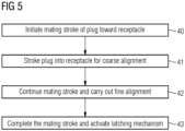
Fig. 5 illustrates a method of mating a wet mate connector using the plug and receptacle of the present invention. In a first step, a mating stroke is initiated 40 to engage a front end of the plug in a front end of a receptacle and carry outcoarse alignment 41 by aligning the receptacle with acoarse alignment feature 23 of the plug front end. The mating stroke continues 42 to carry out fine alignment by engaging a fine alignment key 31 in the receptacle with afine alignment keyway 33 formed in the plug. The latching mechanism is activated, then as the stroke continues 43 contact is made between the plug and receptacle conductors, then the snap ring snaps into position. - While the present invention has been described above by reference to various embodiments, it should be understood that many changes and modifications can be made to the described embodiments. It is therefore intended that the foregoing description be regarded as illustrative rather than limiting, and that it be understood that all equivalents and/or combinations of embodiments are intended to be included in this description.
- The foregoing examples have been provided merely for the purpose of explanation and are in no way to be construed as limiting of the present invention disclosed herein. While the invention has been described with reference to various embodiments, it is understood that the words, which have been used herein, are words of description and illustration, rather than words of limitation. Further, although the invention has been described herein with reference to particular means, materials, and embodiments, the invention is not intended to be limited to the particulars disclosed herein; rather, the invention extends to all functionally equivalent structures, methods and uses, such as are within the scope of the appended claims. Those skilled in the art, having the benefit of the teachings of this specification, may affect numerous modifications thereto and changes may be made without departing from the scope of the invention in its aspects.
- It should be noted that the term "comprising" does not exclude other elements or steps and "a" or "an" does not exclude a plurality. Elements described in association with different embodiments may be combined. It should also be noted that reference signs in the claims should not be construed as limiting the scope of the claims. Although the invention is illustrated and described in detail by the preferred embodiments, the invention is not limited by the examples disclosed, and other variations can be derived therefrom by a person skilled in the art without departing from the scope of the invention.
Claims (7)
- An ROV wetmatable connector comprising a plug (20) and receptacle (30), wherein the plug comprises a plug body (21); and the receptacle comprises a receptacle body (22); wherein the plug comprises a recess (24) circumscribing its forward end, forming part of a coarse alignment feature (23) and rearward of a front surface (50) of the plug body (21); wherein the receptacle body (22) comprises a latching mechanism (25) comprising a fastener or latch adapted to cooperate with the recess (24) in the forward end of the plug, to latch the plug (20) and receptacle (30) together when mated; and, wherein the connector further comprises a plug fine alignment feature comprising a keyway (27) in the plug body; and a receptacle fine alignment feature comprising a key (26, 31) mounted to the receptacle body and adapted to cooperate with the keyway in the plug body to provide fine alignment during mating; characterised in that the coarse alignment feature comprises a series of three truncated cones (51, 52, 53), the first and third of the cones comprising congruent faces (51a, 53a), the first and second cones (51, 52) being joined at their maximum diameter and the second and third cones (52, 53) being joined at their minimum diameter.
- A connector according to claim 1, wherein the key (26, 31) is mounted in an opening (32) in the receptacle body (22).
- A connector according to claim 1 or claim 2, wherein the key (26, 31) is removable from the receptacle body (22).
- A connector according to any of claims 1 to 3, wherein the key (26, 31) comprises a rod, post, or threaded screw.
- A connector according to at least claim 2, wherein the opening (32) in the receptacle body (22) comprises an inner surface shaped to correspond with the key (26, 31).
- A connector according to any preceding claim, wherein the fastener or latch (25) comprises a circlip, snap ring, or retaining ring, or resilient prongs or collet.
- A method of mating a plug and receptacle of a wet mate connector, the method comprising initiating (40) a mating stroke to engage a front end of the plug in a front end of a receptacle and carrying out coarse alignment (41) by aligning the receptacle with a coarse alignment feature of the plug front end, the coarse alignment feature comprising a series of three truncated cones, the first and third of the cones comprising congruent faces, the first and second cones being joined at their maximum diameter and the second and third cones being joined at their minimum diameter; continuing (42) the mating stroke to carry out fine alignment by engaging a fine alignment key in the receptacle with a fine alignment keyway formed in the plug; completing the mating stroke to fasten the plug and receptacle together by activating a latching mechanism comprising a fastener or latch in the receptacle rear end to engage (43) with a rear part of the coarse alignment feature.
Applications Claiming Priority (6)
| Application Number | Priority Date | Filing Date | Title |
|---|---|---|---|
| GBGB2103663.7A GB202103663D0 (en) | 2021-03-17 | 2021-03-17 | Subsea connector |
| GB2103666.0A GB2604884A (en) | 2021-03-17 | 2021-03-17 | Cable connection |
| GBGB2103668.6A GB202103668D0 (en) | 2021-03-17 | 2021-03-17 | Subsea connector |
| GBGB2103664.5A GB202103664D0 (en) | 2021-03-17 | 2021-03-17 | Subsea connector |
| GB2103669.4A GB2604886A (en) | 2021-03-17 | 2021-03-17 | Subsea connector |
| GB2103667.8A GB2604885B (en) | 2021-03-17 | 2021-03-17 | Subsea connector |
Publications (2)
| Publication Number | Publication Date |
|---|---|
| EP4060825A1 EP4060825A1 (en) | 2022-09-21 |
| EP4060825B1 true EP4060825B1 (en) | 2024-12-18 |
Family
ID=80683772
Family Applications (6)
| Application Number | Title | Priority Date | Filing Date |
|---|---|---|---|
| EP22162071.9A Active EP4060830B1 (en) | 2021-03-17 | 2022-03-15 | Cable connection |
| EP22162024.8A Active EP4060822B1 (en) | 2021-03-17 | 2022-03-15 | Subsea connector |
| EP22162015.6A Active EP4060826B1 (en) | 2021-03-17 | 2022-03-15 | Subsea connector |
| EP22162028.9A Pending EP4060827A1 (en) | 2021-03-17 | 2022-03-15 | Subsea connector |
| EP22162014.9A Active EP4060825B1 (en) | 2021-03-17 | 2022-03-15 | Subsea connector |
| EP22162026.3A Pending EP4060823A1 (en) | 2021-03-17 | 2022-03-15 | Subsea connector |
Family Applications Before (4)
| Application Number | Title | Priority Date | Filing Date |
|---|---|---|---|
| EP22162071.9A Active EP4060830B1 (en) | 2021-03-17 | 2022-03-15 | Cable connection |
| EP22162024.8A Active EP4060822B1 (en) | 2021-03-17 | 2022-03-15 | Subsea connector |
| EP22162015.6A Active EP4060826B1 (en) | 2021-03-17 | 2022-03-15 | Subsea connector |
| EP22162028.9A Pending EP4060827A1 (en) | 2021-03-17 | 2022-03-15 | Subsea connector |
Family Applications After (1)
| Application Number | Title | Priority Date | Filing Date |
|---|---|---|---|
| EP22162026.3A Pending EP4060823A1 (en) | 2021-03-17 | 2022-03-15 | Subsea connector |
Country Status (4)
| Country | Link |
|---|---|
| US (6) | US12149023B2 (en) |
| EP (6) | EP4060830B1 (en) |
| CN (6) | CN115117683A (en) |
| BR (6) | BR102022004743A2 (en) |
Families Citing this family (5)
| Publication number | Priority date | Publication date | Assignee | Title |
|---|---|---|---|---|
| EP3657614A1 (en) * | 2018-11-22 | 2020-05-27 | TE Connectivity Industrial GmbH | Electrical plug with specific pin arrangement as well as electrical plug device |
| EP3927931B1 (en) * | 2019-02-20 | 2023-02-08 | FMC Technologies, Inc. | Electrical feedthrough system and methods of use thereof |
| EP3985807A1 (en) * | 2020-10-15 | 2022-04-20 | TE Connectivity Industrial GmbH | Electrical plug with a specific pin arrangement comprising eight data transmission contacts for gigabit application |
| CN115421256B (en) * | 2022-09-30 | 2024-05-10 | 中国科学院长春光学精密机械与物理研究所 | Underwater wet plugging self-cleaning fiber optic pin |
| CN119231239A (en) * | 2024-09-27 | 2024-12-31 | 江苏凡尔科技有限公司 | A crane cable and its matching cable connector |
Family Cites Families (43)
| Publication number | Priority date | Publication date | Assignee | Title |
|---|---|---|---|---|
| US3665368A (en) * | 1970-06-17 | 1972-05-23 | Bendix Corp | Electrical connector |
| US3742427A (en) | 1971-08-26 | 1973-06-26 | A Ballard | Sealable electrical connector |
| US4072381A (en) * | 1975-04-17 | 1978-02-07 | Air-Tex Wire Harness, Inc. | Tractor-trailer electrical connector system |
| US4142770A (en) | 1977-12-27 | 1979-03-06 | Exxon Production Research Company | Subsea electrical connector |
| US5194012A (en) * | 1991-07-30 | 1993-03-16 | Cairns James L | Spark-proof hostile environment connector |
| US5478970A (en) * | 1994-02-03 | 1995-12-26 | D. G. O'brien, Inc. | Apparatus for terminating and interconnecting rigid electrical cable and method |
| US5645442A (en) * | 1995-01-19 | 1997-07-08 | Ocean Design, Inc. | Sealed, Fluid-filled electrical connector |
| US5645438A (en) * | 1995-01-20 | 1997-07-08 | Ocean Design, Inc. | Underwater-mateable connector for high pressure application |
| GB2338119A (en) | 1998-04-29 | 1999-12-08 | Tronic Ltd | Pothead |
| US6464405B2 (en) | 1999-10-14 | 2002-10-15 | Ocean Design, Inc. | Wet-mateable electro-optical connector |
| US6332787B1 (en) * | 2000-08-18 | 2001-12-25 | Ocean Design, Inc. | Wet-mateable electro-optical connector |
| SE525049C2 (en) * | 2002-12-09 | 2004-11-16 | Atlas Copco Tools Ab | Multi-Conductor Connector |
| US7074064B2 (en) * | 2003-07-22 | 2006-07-11 | Pathfinder Energy Services, Inc. | Electrical connector useful in wet environments |
| US7316584B2 (en) | 2005-09-13 | 2008-01-08 | Deutsch Engineered Connecting Devices, Inc. | Matched impedance shielded pair interconnection system for high reliability applications |
| FR2895577B1 (en) * | 2005-12-26 | 2008-04-18 | Carrier Kheops Bac Sa | ELECTRICAL OR OPTICAL CONNECTOR IMMERSIONABLE IN A FLUID ENVIRONMENT |
| US7285003B2 (en) * | 2005-12-30 | 2007-10-23 | Ocean Design, Inc. | Harsh environment connector including end cap and latching features and associated methods |
| US8303337B2 (en) * | 2007-06-06 | 2012-11-06 | Veedims, Llc | Hybrid cable for conveying data and power |
| US7695301B2 (en) * | 2008-08-07 | 2010-04-13 | Teledyne Odi, Inc. | Submersible connector with secondary sealing device |
| US7828573B2 (en) * | 2008-10-28 | 2010-11-09 | S&N Pump Company | Subsea electrical connector and method |
| US7736159B1 (en) * | 2009-04-07 | 2010-06-15 | Tyco Electronics Corporation | Pluggable connector with differential pairs |
| US7959454B2 (en) * | 2009-07-23 | 2011-06-14 | Teledyne Odi, Inc. | Wet mate connector |
| US8267707B2 (en) * | 2010-02-03 | 2012-09-18 | Tronic Limited | Underwater or sub sea connectors |
| US8251732B2 (en) * | 2010-06-28 | 2012-08-28 | Maxi-Seal Harness Systems Inc. | Power input electrical connector |
| GB2567759B (en) * | 2012-07-24 | 2019-10-23 | Accessesp Uk Ltd | Downhole electrical wet connector |
| GB2509482B (en) * | 2012-10-04 | 2016-06-15 | Siemens Ag | Downhole cable termination systems |
| US11336058B2 (en) * | 2013-03-14 | 2022-05-17 | Aptiv Technologies Limited | Shielded cable assembly |
| EP2853680A1 (en) * | 2013-09-30 | 2015-04-01 | Siemens Aktiengesellschaft | Flushing arrangement |
| WO2015068050A1 (en) * | 2013-11-08 | 2015-05-14 | Onesubsea Ip Uk Limited | Wet mate connector |
| DE202014009498U1 (en) * | 2014-11-28 | 2015-01-15 | Rosenberger Hochfrequenztechnik Gmbh & Co. Kg | Cable with stranded wire pairs |
| US9508467B2 (en) * | 2015-01-30 | 2016-11-29 | Yfc-Boneagle Electric Co., Ltd. | Cable for integrated data transmission and power supply |
| US20170005448A1 (en) * | 2015-07-02 | 2017-01-05 | Teledyne Instruments, Inc. | Flush and fill tool for subsea connectors |
| EP3166184A1 (en) * | 2015-11-04 | 2017-05-10 | Siemens Aktiengesellschaft | Subsea screen connection assembly |
| US10704353B2 (en) | 2015-12-22 | 2020-07-07 | Teledyne Instruments, Inc. | Modular electrical feedthrough |
| EP3211726B1 (en) * | 2016-02-23 | 2021-05-05 | Siemens Energy Global GmbH & Co. KG | Connector unit comprising two connector parts and method for operating such connector unit |
| NO342320B1 (en) * | 2016-06-03 | 2018-05-07 | Benestad Solutions As | High voltage subsea connection assembly |
| US10181692B2 (en) * | 2016-11-07 | 2019-01-15 | Corning Optical Communications Rf Llc | Coaxial connector with translating grounding collar for establishing a ground path with a mating connector |
| US9772452B1 (en) * | 2017-01-27 | 2017-09-26 | John Robert Toth | Hybrid connection system having separately sealed plug and receptacle chambers |
| EP3396784B1 (en) * | 2017-04-28 | 2020-12-23 | Precision Subsea AS | Housing assembly for a wet-mate connector, in particular for deep-sea applications, having a latch mechanism on the outside |
| CN111384633A (en) * | 2018-12-28 | 2020-07-07 | 中天海洋系统有限公司 | Watertight connector |
| DE102019106980B3 (en) * | 2019-03-19 | 2020-07-02 | Harting Electric Gmbh & Co. Kg | Contact carriers and connectors for a shielded hybrid contact arrangement |
| GB201912501D0 (en) * | 2019-08-30 | 2019-10-16 | Siemens Ag | Subsea connector |
| US10958013B1 (en) * | 2020-01-21 | 2021-03-23 | F Time Technology Industrial Co., Ltd. | Waterproof connector |
| US10946939B1 (en) * | 2020-04-22 | 2021-03-16 | Kai Concepts, LLC | Watercraft having a waterproof container and a waterproof electrical connector |
-
2022
- 2022-03-15 EP EP22162071.9A patent/EP4060830B1/en active Active
- 2022-03-15 CN CN202210255872.7A patent/CN115117683A/en active Pending
- 2022-03-15 EP EP22162024.8A patent/EP4060822B1/en active Active
- 2022-03-15 CN CN202210255857.2A patent/CN115133333A/en active Pending
- 2022-03-15 CN CN202210253309.6A patent/CN115117682A/en active Pending
- 2022-03-15 BR BR102022004743-0A patent/BR102022004743A2/en unknown
- 2022-03-15 US US17/694,815 patent/US12149023B2/en active Active
- 2022-03-15 EP EP22162015.6A patent/EP4060826B1/en active Active
- 2022-03-15 EP EP22162028.9A patent/EP4060827A1/en active Pending
- 2022-03-15 US US17/694,798 patent/US12149022B2/en active Active
- 2022-03-15 BR BR102022004734-0A patent/BR102022004734A2/en unknown
- 2022-03-15 BR BR102022004747-2A patent/BR102022004747A2/en unknown
- 2022-03-15 EP EP22162014.9A patent/EP4060825B1/en active Active
- 2022-03-15 BR BR102022004732-4A patent/BR102022004732A2/en unknown
- 2022-03-15 BR BR102022004729-4A patent/BR102022004729A2/en unknown
- 2022-03-15 US US17/694,788 patent/US11942720B2/en active Active
- 2022-03-15 CN CN202210251370.7A patent/CN115173136A/en active Pending
- 2022-03-15 US US17/694,805 patent/US12095201B2/en active Active
- 2022-03-15 EP EP22162026.3A patent/EP4060823A1/en active Pending
- 2022-03-15 CN CN202210253202.1A patent/CN115117681A/en active Pending
- 2022-03-15 BR BR102022004727-8A patent/BR102022004727A2/en unknown
- 2022-03-15 US US17/694,778 patent/US11942719B2/en active Active
- 2022-03-15 CN CN202210254311.5A patent/CN115133332A/en active Pending
- 2022-03-15 US US17/694,769 patent/US20220302632A1/en active Pending
Also Published As
| Publication number | Publication date |
|---|---|
| BR102022004747A2 (en) | 2022-09-20 |
| US20220302637A1 (en) | 2022-09-22 |
| US20220302635A1 (en) | 2022-09-22 |
| CN115133332A (en) | 2022-09-30 |
| US12149023B2 (en) | 2024-11-19 |
| US11942719B2 (en) | 2024-03-26 |
| EP4060825A1 (en) | 2022-09-21 |
| EP4060830B1 (en) | 2025-01-01 |
| US12095201B2 (en) | 2024-09-17 |
| EP4060830A1 (en) | 2022-09-21 |
| EP4060822B1 (en) | 2025-02-19 |
| US20220302632A1 (en) | 2022-09-22 |
| EP4060827A1 (en) | 2022-09-21 |
| BR102022004734A2 (en) | 2022-09-27 |
| BR102022004727A2 (en) | 2022-09-20 |
| US11942720B2 (en) | 2024-03-26 |
| CN115117683A (en) | 2022-09-27 |
| BR102022004743A2 (en) | 2022-09-20 |
| EP4060826A1 (en) | 2022-09-21 |
| EP4060823A1 (en) | 2022-09-21 |
| CN115133333A (en) | 2022-09-30 |
| CN115117682A (en) | 2022-09-27 |
| CN115117681A (en) | 2022-09-27 |
| US20220302634A1 (en) | 2022-09-22 |
| US20220302636A1 (en) | 2022-09-22 |
| EP4060822A1 (en) | 2022-09-21 |
| BR102022004732A2 (en) | 2022-09-20 |
| US20220302633A1 (en) | 2022-09-22 |
| CN115173136A (en) | 2022-10-11 |
| BR102022004729A2 (en) | 2022-09-20 |
| EP4060826B1 (en) | 2024-12-11 |
| US12149022B2 (en) | 2024-11-19 |
Similar Documents
| Publication | Publication Date | Title |
|---|---|---|
| EP4060825B1 (en) | Subsea connector | |
| EP2854235B1 (en) | Connector unit | |
| CN101202392B (en) | Electrical connector assembly of refrigerator door | |
| US7503794B2 (en) | Electrical plug connector for solar panel | |
| EP0566615B1 (en) | Connecting apparatus | |
| CN101420081B (en) | Fast locking and detaching mechanism applied to coaxial electric connector | |
| US7097515B2 (en) | Subsea electrical connector | |
| CN102646894A (en) | Rapid locking coaxial connector | |
| GB2431702A (en) | Underwater push-fit connector | |
| US6237690B1 (en) | Connector assembly | |
| US20040157500A1 (en) | Circuit board and socket assembly | |
| EP1657576B1 (en) | well head assembly with an underwater connector | |
| US10141682B2 (en) | Subsea electrical connector with removable ROV mating tool | |
| US20240243515A1 (en) | Connector coupler | |
| US7753741B2 (en) | Electrical interconnection systems and methods of assembling the same | |
| CN219350823U (en) | Socket assembly of plug-in connector and plug-in connector | |
| GB2619320A (en) | Termination assembly | |
| GB2604885A (en) | Subsea connector |
Legal Events
| Date | Code | Title | Description |
|---|---|---|---|
| PUAI | Public reference made under article 153(3) epc to a published international application that has entered the european phase |
Free format text: ORIGINAL CODE: 0009012 |
|
| STAA | Information on the status of an ep patent application or granted ep patent |
Free format text: STATUS: THE APPLICATION HAS BEEN PUBLISHED |
|
| AK | Designated contracting states |
Kind code of ref document: A1 Designated state(s): AL AT BE BG CH CY CZ DE DK EE ES FI FR GB GR HR HU IE IS IT LI LT LU LV MC MK MT NL NO PL PT RO RS SE SI SK SM TR |
|
| STAA | Information on the status of an ep patent application or granted ep patent |
Free format text: STATUS: REQUEST FOR EXAMINATION WAS MADE |
|
| 17P | Request for examination filed |
Effective date: 20230320 |
|
| RBV | Designated contracting states (corrected) |
Designated state(s): AL AT BE BG CH CY CZ DE DK EE ES FI FR GB GR HR HU IE IS IT LI LT LU LV MC MK MT NL NO PL PT RO RS SE SI SK SM TR |
|
| GRAP | Despatch of communication of intention to grant a patent |
Free format text: ORIGINAL CODE: EPIDOSNIGR1 |
|
| STAA | Information on the status of an ep patent application or granted ep patent |
Free format text: STATUS: GRANT OF PATENT IS INTENDED |
|
| RIC1 | Information provided on ipc code assigned before grant |
Ipc: H01R 13/6471 20110101ALI20240710BHEP Ipc: H01R 13/6582 20110101ALI20240710BHEP Ipc: H01R 13/6591 20110101ALI20240710BHEP Ipc: H01R 13/523 20060101ALI20240710BHEP Ipc: H01R 13/627 20060101ALI20240710BHEP Ipc: H01R 13/629 20060101AFI20240710BHEP |
|
| INTG | Intention to grant announced |
Effective date: 20240807 |
|
| GRAS | Grant fee paid |
Free format text: ORIGINAL CODE: EPIDOSNIGR3 |
|
| GRAA | (expected) grant |
Free format text: ORIGINAL CODE: 0009210 |
|
| STAA | Information on the status of an ep patent application or granted ep patent |
Free format text: STATUS: THE PATENT HAS BEEN GRANTED |
|
| AK | Designated contracting states |
Kind code of ref document: B1 Designated state(s): AL AT BE BG CH CY CZ DE DK EE ES FI FR GB GR HR HU IE IS IT LI LT LU LV MC MK MT NL NO PL PT RO RS SE SI SK SM TR |
|
| REG | Reference to a national code |
Ref country code: CH Ref legal event code: EP |
|
| REG | Reference to a national code |
Ref country code: DE Ref legal event code: R096 Ref document number: 602022008717 Country of ref document: DE |
|
| REG | Reference to a national code |
Ref country code: IE Ref legal event code: FG4D |