EP4013113A1 - Procédé et appareil de traitement de données - Google Patents
Procédé et appareil de traitement de données Download PDFInfo
- Publication number
- EP4013113A1 EP4013113A1 EP21203077.9A EP21203077A EP4013113A1 EP 4013113 A1 EP4013113 A1 EP 4013113A1 EP 21203077 A EP21203077 A EP 21203077A EP 4013113 A1 EP4013113 A1 EP 4013113A1
- Authority
- EP
- European Patent Office
- Prior art keywords
- rlc
- sdu
- pdu
- field
- layer
- Prior art date
- Legal status (The legal status is an assumption and is not a legal conclusion. Google has not performed a legal analysis and makes no representation as to the accuracy of the status listed.)
- Pending
Links
- 238000003672 processing method Methods 0.000 title claims abstract description 18
- 238000012545 processing Methods 0.000 claims abstract description 167
- 238000000034 method Methods 0.000 claims description 100
- 238000004891 communication Methods 0.000 claims description 16
- 238000005259 measurement Methods 0.000 description 90
- 238000010586 diagram Methods 0.000 description 27
- 230000011218 segmentation Effects 0.000 description 23
- 238000005516 engineering process Methods 0.000 description 17
- 230000006870 function Effects 0.000 description 14
- 230000005540 biological transmission Effects 0.000 description 4
- 230000006837 decompression Effects 0.000 description 3
- 235000019800 disodium phosphate Nutrition 0.000 description 3
- 230000006835 compression Effects 0.000 description 2
- 238000007906 compression Methods 0.000 description 2
- 238000013507 mapping Methods 0.000 description 2
- 238000012986 modification Methods 0.000 description 2
- 230000004048 modification Effects 0.000 description 2
- 238000003491 array Methods 0.000 description 1
- 238000011161 development Methods 0.000 description 1
- 230000018109 developmental process Effects 0.000 description 1
- 230000003287 optical effect Effects 0.000 description 1
- 230000000717 retained effect Effects 0.000 description 1
- 230000011664 signaling Effects 0.000 description 1
- 230000001960 triggered effect Effects 0.000 description 1
Images


Classifications
-
- H—ELECTRICITY
- H04—ELECTRIC COMMUNICATION TECHNIQUE
- H04L—TRANSMISSION OF DIGITAL INFORMATION, e.g. TELEGRAPHIC COMMUNICATION
- H04L69/00—Network arrangements, protocols or services independent of the application payload and not provided for in the other groups of this subclass
- H04L69/22—Parsing or analysis of headers
-
- H—ELECTRICITY
- H04—ELECTRIC COMMUNICATION TECHNIQUE
- H04L—TRANSMISSION OF DIGITAL INFORMATION, e.g. TELEGRAPHIC COMMUNICATION
- H04L1/00—Arrangements for detecting or preventing errors in the information received
- H04L1/0078—Avoidance of errors by organising the transmitted data in a format specifically designed to deal with errors, e.g. location
- H04L1/0084—Formats for payload data
-
- H—ELECTRICITY
- H04—ELECTRIC COMMUNICATION TECHNIQUE
- H04L—TRANSMISSION OF DIGITAL INFORMATION, e.g. TELEGRAPHIC COMMUNICATION
- H04L1/00—Arrangements for detecting or preventing errors in the information received
- H04L1/12—Arrangements for detecting or preventing errors in the information received by using return channel
- H04L1/16—Arrangements for detecting or preventing errors in the information received by using return channel in which the return channel carries supervisory signals, e.g. repetition request signals
- H04L1/1607—Details of the supervisory signal
- H04L1/1685—Details of the supervisory signal the supervisory signal being transmitted in response to a specific request, e.g. to a polling signal
-
- H—ELECTRICITY
- H04—ELECTRIC COMMUNICATION TECHNIQUE
- H04L—TRANSMISSION OF DIGITAL INFORMATION, e.g. TELEGRAPHIC COMMUNICATION
- H04L1/00—Arrangements for detecting or preventing errors in the information received
- H04L1/12—Arrangements for detecting or preventing errors in the information received by using return channel
- H04L1/16—Arrangements for detecting or preventing errors in the information received by using return channel in which the return channel carries supervisory signals, e.g. repetition request signals
- H04L1/18—Automatic repetition systems, e.g. Van Duuren systems
- H04L1/1829—Arrangements specially adapted for the receiver end
- H04L1/1832—Details of sliding window management
-
- H—ELECTRICITY
- H04—ELECTRIC COMMUNICATION TECHNIQUE
- H04L—TRANSMISSION OF DIGITAL INFORMATION, e.g. TELEGRAPHIC COMMUNICATION
- H04L1/00—Arrangements for detecting or preventing errors in the information received
- H04L1/12—Arrangements for detecting or preventing errors in the information received by using return channel
- H04L1/16—Arrangements for detecting or preventing errors in the information received by using return channel in which the return channel carries supervisory signals, e.g. repetition request signals
- H04L1/18—Automatic repetition systems, e.g. Van Duuren systems
- H04L1/1829—Arrangements specially adapted for the receiver end
- H04L1/1848—Time-out mechanisms
-
- H—ELECTRICITY
- H04—ELECTRIC COMMUNICATION TECHNIQUE
- H04L—TRANSMISSION OF DIGITAL INFORMATION, e.g. TELEGRAPHIC COMMUNICATION
- H04L1/00—Arrangements for detecting or preventing errors in the information received
- H04L1/12—Arrangements for detecting or preventing errors in the information received by using return channel
- H04L1/16—Arrangements for detecting or preventing errors in the information received by using return channel in which the return channel carries supervisory signals, e.g. repetition request signals
- H04L1/18—Automatic repetition systems, e.g. Van Duuren systems
- H04L1/1867—Arrangements specially adapted for the transmitter end
- H04L1/187—Details of sliding window management
-
- H—ELECTRICITY
- H04—ELECTRIC COMMUNICATION TECHNIQUE
- H04L—TRANSMISSION OF DIGITAL INFORMATION, e.g. TELEGRAPHIC COMMUNICATION
- H04L5/00—Arrangements affording multiple use of the transmission path
- H04L5/003—Arrangements for allocating sub-channels of the transmission path
- H04L5/0044—Allocation of payload; Allocation of data channels, e.g. PDSCH or PUSCH
-
- H—ELECTRICITY
- H04—ELECTRIC COMMUNICATION TECHNIQUE
- H04L—TRANSMISSION OF DIGITAL INFORMATION, e.g. TELEGRAPHIC COMMUNICATION
- H04L69/00—Network arrangements, protocols or services independent of the application payload and not provided for in the other groups of this subclass
- H04L69/04—Protocols for data compression, e.g. ROHC
-
- H—ELECTRICITY
- H04—ELECTRIC COMMUNICATION TECHNIQUE
- H04L—TRANSMISSION OF DIGITAL INFORMATION, e.g. TELEGRAPHIC COMMUNICATION
- H04L69/00—Network arrangements, protocols or services independent of the application payload and not provided for in the other groups of this subclass
- H04L69/30—Definitions, standards or architectural aspects of layered protocol stacks
- H04L69/32—Architecture of open systems interconnection [OSI] 7-layer type protocol stacks, e.g. the interfaces between the data link level and the physical level
- H04L69/322—Intralayer communication protocols among peer entities or protocol data unit [PDU] definitions
-
- H—ELECTRICITY
- H04—ELECTRIC COMMUNICATION TECHNIQUE
- H04L—TRANSMISSION OF DIGITAL INFORMATION, e.g. TELEGRAPHIC COMMUNICATION
- H04L9/00—Cryptographic mechanisms or cryptographic arrangements for secret or secure communications; Network security protocols
- H04L9/40—Network security protocols
-
- H—ELECTRICITY
- H04—ELECTRIC COMMUNICATION TECHNIQUE
- H04W—WIRELESS COMMUNICATION NETWORKS
- H04W28/00—Network traffic management; Network resource management
- H04W28/02—Traffic management, e.g. flow control or congestion control
- H04W28/06—Optimizing the usage of the radio link, e.g. header compression, information sizing, discarding information
-
- H—ELECTRICITY
- H04—ELECTRIC COMMUNICATION TECHNIQUE
- H04W—WIRELESS COMMUNICATION NETWORKS
- H04W76/00—Connection management
- H04W76/10—Connection setup
- H04W76/11—Allocation or use of connection identifiers
-
- H—ELECTRICITY
- H04—ELECTRIC COMMUNICATION TECHNIQUE
- H04W—WIRELESS COMMUNICATION NETWORKS
- H04W80/00—Wireless network protocols or protocol adaptations to wireless operation
- H04W80/02—Data link layer protocols
-
- H—ELECTRICITY
- H04—ELECTRIC COMMUNICATION TECHNIQUE
- H04W—WIRELESS COMMUNICATION NETWORKS
- H04W80/00—Wireless network protocols or protocol adaptations to wireless operation
- H04W80/08—Upper layer protocols
-
- H—ELECTRICITY
- H04—ELECTRIC COMMUNICATION TECHNIQUE
- H04L—TRANSMISSION OF DIGITAL INFORMATION, e.g. TELEGRAPHIC COMMUNICATION
- H04L5/00—Arrangements affording multiple use of the transmission path
- H04L5/0091—Signalling for the administration of the divided path, e.g. signalling of configuration information
- H04L5/0094—Indication of how sub-channels of the path are allocated
-
- H—ELECTRICITY
- H04—ELECTRIC COMMUNICATION TECHNIQUE
- H04W—WIRELESS COMMUNICATION NETWORKS
- H04W28/00—Network traffic management; Network resource management
- H04W28/02—Traffic management, e.g. flow control or congestion control
- H04W28/06—Optimizing the usage of the radio link, e.g. header compression, information sizing, discarding information
- H04W28/065—Optimizing the usage of the radio link, e.g. header compression, information sizing, discarding information using assembly or disassembly of packets
Definitions
- This application relates to the field of communications technologies, and in particular, to a data processing method, apparatus, and system.
- this application provides a data processing method, apparatus, and system, so as to improve data processing efficiency.
- a data processing method is performed by a data sending apparatus and includes the following steps: receiving a data packet from a Packet Data Convergence Protocol (PDCP) layer, where the data packet is used as a Radio Link Control (RLC) service data unit (SDU); and encapsulating the RLC SDU into at least one RLC protocol data unit (PDU), where each the RLC PDU encapsulated at an RLC layer by the data sending apparatus includes a header and a payload, and the payload is used to carry data from a single RLC SDU.
- PDCP Packet Data Convergence Protocol
- RLC Radio Link Control
- PDU RLC protocol data unit
- a data processing apparatus located at a transmit end and including means (means) or units configured to perform the steps in the first aspect.
- a data processing apparatus including a processor and a memory.
- the memory is configured to store a program, and the processor invokes the program stored in the memory, to perform the method provided in the first aspect of this application.
- this application provides a data processing apparatus, including at least one processing element (or chip) configured to perform the method in the first aspect.
- this application provides a program.
- the program is used to perform the method in the first aspect when being executed by a processor.
- a program product for example, a computer readable storage medium, including the program in the fifth aspect.
- a data processing method is performed by a data receiving apparatus and includes the following steps: receiving, at an RLC layer, a data packet from a MAC layer, where the data packet includes an RLC PDU, the RLC PDU includes a header and a payload, and the payload is used to carry data from a single RLC SDU; and when determining, based on the header of the RLC PDU, that the payload of the RLC PDU is a complete RLC SDU, obtaining the RLC SDU, and sending the RLC SDU to a PDCP layer; and/or when determining, based on the header of the RLC PDU, that the payload of the RLC PDU is a segment of an RLC SDU, obtaining all segments of the RLC SDU, restoring all the segments to the RLC SDU, and sending the RLC SDU to a PDCP layer.
- a data processing apparatus located at a receive end and including means (means) or units configured to perform the steps in the seventh aspect.
- a data processing apparatus including a processor and a memory.
- the memory is configured to store a program, and the processor invokes the program stored in the memory, to perform the method provided in the seventh aspect of this application.
- this application provides a data processing apparatus, including at least one processing element (or chip) configured to perform the method in the seventh aspect.
- this application provides a program.
- the program is used to perform the method in the seventh aspect when being executed by a processor.
- a program product for example, a computer readable storage medium, including the program in the eleventh aspect.
- the data sending apparatus does not perform concatenation processing at the RLC layer on data packets.
- the payload of each assembled RLC PDU is used to carry the data from a single RLC SDU.
- the payload of the RLC PDU does not include data of another RLC SDU. That is , the data sending apparatus no longer performs concatenation processing at the RLC layer on RLC SDUs. In this way, concatenation processing at the transmit end can be reduced, and processing complexity and processing latency can be reduced.
- the receive end may reorder, at the RLC layer, segments of a single RLC SDU only, without a need to reorder RLC SDUs. Therefore, processing at the receive end can be simplified, and processing complexity and processing latency at the receive end can be reduced.
- the header of the RLC PDU includes a segment indicator (SI) field, used to indicate what is encapsulated into the RLC PDU where the SI field is located is a complete RLC SDU or a segment of an RLC SDU.
- SI segment indicator
- the SI field includes two bits, and values of the SI field are described as follows:
- the SI field includes one bit, and values of the SI field are described as follows: a first value is used to indicate that what is encapsulated into the RLC PDU where the SI field is located is a complete RLC SDU or indicate that what is encapsulated into the RLC PDU where the SI field is located is a last segment of an RLC SDU, and a second value is used to indicate that what is encapsulated into the RLC PDU where the SI field is located is a first segment or a middle segment of an RLC SDU.
- the header of the RLC PDU further includes a segment offset (SO) field, used to indicate a byte offset, of a first byte in a payload of the RLC PDU where the SO field is located, within an RLC SDU to which the payload belongs.
- SO segment offset
- the header of the RLC PDU further includes a sequence number (SN) field, and when one RLC SDU is encapsulated into a plurality of RLC PDUs, SNs in SN fields in headers of the plurality of RLC PDUs are the same.
- SN sequence number
- the SN field may be used to indicate an RLC SDU to which data transmitted in the RLC PDU where the SN field is located belongs.
- an SN in the SN field is configured by the PDCP layer.
- the header of the RLC PDU further includes a length indicator (LI) field, used to indicate a length of a payload in the RLC PDU where the LI field is located.
- LI length indicator
- the header of the RLC PDU further includes a data/control field, used to indicate whether a data packet or a control packet is transmitted in the RLC PDU where the data/control field is located.
- a process where the data sending apparatus encapsulates the RLC SDU into at least one RLC PDU includes: encapsulating the RLC SDU into the at least one RLC PDU based on an indication from a MAC layer; or encapsulating the RLC SDU into the at least one RLC PDU based on a preset RLC PDU size.
- a unit that encapsulates the RLC SDU into the at least one RLC PDU is configured to: encapsulate the RLC SDU into the at least one RLC PDU based on the indication from the MAC layer; or encapsulate the RLC SDU into the at least one RLC PDU based on the preset RLC PDU size.
- the data sending apparatus may further send an RLC data packet to the MAC layer.
- the RLC data packet includes one or more RLC PDUs.
- the data processing apparatus further includes a unit that performs this step.
- the data sending apparatus uses the RLC data packet as a MAC SDU and encapsulates the MAC SDU into a MAC PDU.
- the MAC PDU includes a MAC header and a MAC payload
- the MAC header includes at least one subheader
- each subheader corresponds to one logical channel
- the subheader includes a first extension field and a second extension field
- the first extension field is used to indicate whether the MAC PDU further includes another subheader or further includes data of another logical channel
- the second extension field is used to indicate whether the MAC PDU further includes other data of a logical channel corresponding to a subheader where the second extension field is located.
- the data processing apparatus further includes a unit that performs this step.
- the data receiving apparatus when the RLC SDU sent to the PDCP layer does not include a PDCP sequence number, the data receiving apparatus sends the SN in the SN field to the PDCP layer.
- the PDCP sequence number is a sequence number allocated to the PDCP PDU when the transmit end assembles the PDCP PDU.
- the data receiving apparatus may distinguish between the RLC PDUs based on the LI field.
- the data receiving apparatus when the RLC layer uses an unacknowledged mode (UM), the data receiving apparatus maintains, at the RLC layer, a reordering window, and the data processing method further includes: when a first RLC PDU is out of the reordering window and the first RLC PDU includes a segment of an RLC SDU that fails to be reassembled, discarding, by the data receiving apparatus, all received RLC PDUs corresponding to the RLC SDU that fails to be reassembled.
- the data processing apparatus further includes a unit configured to perform this step.
- the data receiving apparatus may notify the PDCP layer of the discarded RLC SDU.
- the data processing apparatus further includes a unit configured to perform this step.
- the data receiving apparatus when SNs of received RLC PDUs are discontinuous, the data receiving apparatus starts a timer at a first discontinuous position.
- the timer may be referred to as an associated timer.
- the data receiving apparatus stops the timer.
- the timer expires, that is, RLC PDUs that include missing SNs are not received before the timer expires, the data receiving apparatus moves a lower edge of the reordering window to a position of an SN corresponding to the first discontinuous position, namely, a position of an SN corresponding to a first RLC SDU that is not delivered to an upper layer.
- the SN is referred to as a first SN.
- the data receiving apparatus discards an RLC PDU that is not delivered to the PDCP layer and whose SN is before the first SN. Further, optionally, the data receiving apparatus notifies the PDCP layer of an SN of an RLC SDU corresponding to the discarded RLC PDU.
- the method before the receiving, by a data receiving apparatus, a data packet from a MAC layer, the method further includes: obtaining, at the MAC layer, a MAC SDU based on a format of a MAC PDU, and using the MAC SDU as the data packet sent to the RLC layer.
- the format of the MAC PDU is as follows:
- the MAC PDU includes a MAC header and a MAC payload, the MAC header includes at least one subheader, each subheader corresponds to one logical channel, the subheader includes a first extension field and a second extension field, the first extension field is used to indicate whether the MAC PDU further includes another subheader or further includes data of another logical channel, and the second extension field is used to indicate whether the MAC PDU further includes other data of a logical channel corresponding to a subheader where the second extension field is located.
- an RLC PDU structure is provided.
- the RLC PDU includes a header and a payload, and the payload is used to carry data from a single RLC SDU.
- the header of the RLC PDU is the same as that in the foregoing descriptions.
- a data processing method is performed by a data sending apparatus and includes the following steps: receiving an RLC data packet from an RLC layer, where the RLC data packet includes at least one RLC PDU; and using the RLC data packet as a MAC SDU and encapsulating the MAC SDU into a MAC PDU, where the MAC PDU includes a MAC header and a MAC payload, the MAC header includes at least one subheader, each subheader corresponds to one logical channel, the subheader includes a first extension field (E field) and a second extension field (H field), the first extension field is used to indicate whether the MAC PDU further includes another subheader or further includes data of another logical channel, and the second extension field is used to indicate whether the MAC PDU further includes other data of a logical channel corresponding to a subheader where the second extension field is located.
- E field first extension field
- H field second extension field
- a data processing method is provided. The method is performed by a data receiving apparatus and includes the following steps: receiving a MAC PDU from a PDCP layer; obtaining a MAC SDU based on a format of the MAC PDU; and sending the MAC SDU to an RLC layer.
- the format of the MAC PDU is as follows:
- the MAC PDU includes a MAC header and a MAC payload, the MAC header includes at least one subheader, each subheader corresponds to one logical channel, the subheader includes a first extension field (E field) and a second extension field (H field), the first extension field is used to indicate whether the MAC PDU further includes another subheader or further includes data of another logical channel, and the second extension field is used to indicate whether the MAC PDU further includes other data of a logical channel corresponding to a subheader where the second extension field is located.
- E field first extension field
- H field second extension field
- a data processing apparatus located at a transmit end and including means (means) or units configured to perform the steps in the fourteenth aspect.
- a data processing apparatus located at a receive end and including means (means) or units configured to perform the steps in the fifteenth aspect.
- a data processing apparatus located at a transmit end and including a processor and a memory.
- the memory is configured to store a program, and the processor invokes the program stored in the memory, to perform the method provided in the fourteenth aspect of this application.
- a data processing apparatus located at a receive end and including a processor and a memory.
- the memory is configured to store a program, and the processor invokes the program stored in the memory, to perform the method provided in the fifteenth aspect of this application.
- this application provides a data processing apparatus, located at a transmit end and including at least one processing element (or chip) configured to perform the method in the fourteenth aspect.
- this application provides a data processing apparatus, located at a receive end and including at least one processing element (or chip) configured to perform the method in the fifteenth aspect.
- this application provides a program.
- the program is used to perform the method in the fourteenth aspect or the fifteenth aspect when being executed by a processor.
- a program product is provided, for example, a computer readable storage medium, including the program in the nineteenth aspect.
- the subheader of the MAC PDU further includes a logical channel identifier (LCID) field, used to indicate a logical channel to which a payload associated with the subheader belongs.
- LCID logical channel identifier
- the subheader of the MAC PDU further includes a first length indicator field (F field) and a second length indicator field (L field).
- the first length indicator field is used to indicate a length of the second length indicator field
- the second length indicator field is used to indicate a length of a payload associated with the subheader where the second length indicator field is located.
- a data processing method is provided.
- the method is used on a data sending apparatus, the data sending apparatus maintains, at a PDCP layer, a PDCP transmit window, and the method includes: sending, at the PDCP layer by the data sending apparatus, PDCP PDUs to an RLC layer; and when a quantity of the sent PDCP PDUs reaches a maximum quantity of PDCP PDUs that can be accommodated by the PDCP transmit window, and the data sending apparatus does not receive a successful feedback at the PDCP layer, stopping, by the data sending apparatus, sending a PDCP PDU.
- the success feedback is a status report fed back at the RLC layer by the data sending apparatus, indicating that all or some PDCP PDUs are successfully sent, or the success feedback is a status report fed back by a data receiving apparatus, indicating that all or some PDCP PDUs are successfully received.
- a data processing apparatus located at a transmit end and including means (means) or units configured to perform the steps in the twenty-first aspect.
- a data processing apparatus including a processor and a memory.
- the memory is configured to store a program, and the processor invokes the program stored in the memory, to perform the method provided in the twenty-first aspect of this application.
- this application provides a data processing apparatus, including at least one processing element (or chip) configured to perform the method in the twenty-first aspect.
- this application provides a program.
- the program is used to perform the method in the twenty-first aspect when being executed by a processor.
- a program product for example, a computer readable storage medium, including the program in the twenty-fifth aspect.
- the transmit end may maintain, at the PDCP layer, a PDCP transmit window, to control data packet sending at the PDCP layer. This can effectively reduce a problem that PDCP SNs are repeated when an amount of data sent by the transmit end exceeds a range of data that can be indicated by the PDCP SN, thereby resolving a problem that a receive end cannot correctly distinguish and process a plurality of data packets that have same SNs and that are received at the PDCP layer.
- a size of the PDCP transmit window is determined based on a PDCP sequence number or is preset.
- the data sending apparatus sends, at the PDCP layer, the PDCP sequence number to the RLC layer.
- the PDCP PDU carries the PDCP sequence number, or the PDCP sequence number is independent of the PDCP PDU.
- the PDCP sequence number is a sequence number allocated to the PDCP PDU when the data sending apparatus assembles the PDCP PDU.
- FIG. 1 is a schematic diagram of a communication scenario according to an embodiment of this application.
- a terminal 110 accesses to a wireless network through a RAN device 120, to obtain a service of an external network (for example, the Internet) through the wireless network, or to communicate with another terminal through the wireless network.
- an external network for example, the Internet
- the RAN device 120 In a downlink transmission direction, the RAN device 120 is used as a transmit end, and the terminal 110 may be used as a receive end.
- the terminal 110 In an uplink transmission direction, the terminal 110 is used as a transmit end, and the RAN device 120 is used as a receive end.
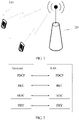
- FIG 2 is a schematic diagram of a user plane protocol stack followed by communication between a terminal and a RAN device according to an embodiment of this application.
- the protocol stack includes a Packet Data Convergence Protocol (Packet Data Convergence Protocol, PDCP) layer, a Radio Link Control (Radio Link Control, RLC) layer, a Media Access Control (Media Access Control, MAC) layer, and a physical (physical, PHY) layer.
- PDCP Packet Data Convergence Protocol
- RLC Radio Link Control
- MAC Media Access Control
- L2 layer-2
- main functions of the PDCP layer include encryption/decryption, header compression/header decompression, integrity protection, and the like.
- Main functions of the RLC layer include segmentation, concatenation, reordering, automatic repeat request (automatic repeat request, ARQ), and the like.
- Main functions of the MAC layer include multiplexing, scheduling, hybrid automatic repeat request (hybrid automatic repeat request, HARQ), and the like.
- functions of the RLC layer are adjusted, and when encapsulating a data packet from the PDCP layer, the RLC layer performs segmentation only and does not perform concatenation. In this way, concatenation processing at the transmit end can be reduced, and processing complexity and processing latency can be reduced.
- a transmit end in this embodiment of this application may also be referred to as a data sending apparatus, and a receive end may also be referred to as a data receiving apparatus.
- FIG 3 is a schematic diagram of a data processing method according to an embodiment of this application. As shown in FIG 3 , the method is used at a transmit end, that is, performed by the transmit end, and the transmit end may also be referred to as a data sending apparatus. The method includes the following steps:
- the transmit end does not perform concatenation processing at the RLC layer on the data packet.
- the payload of each assembled RLC PDU is used to carry data from a single RLC SDU.
- the payload of the RLC PDU does not include data of another RLC SDU. That is, the transmit end no longer performs concatenation processing at the RLC layer on RLC SDUs. In this way, concatenation processing at the transmit end can be reduced, and processing complexity and processing latency can be reduced.
- the receive end may reorder, at the RLC layer, segments of a single RLC SDU only, without a need to reorder RLC SDUs. Therefore, processing at the receive end can be simplified. This is described in detail in the following embodiments.
- the header of the RLC PDU may be further simplified to reduce header overheads of the RLC PDU.
- an RLC PDU format in existing technology may still be used, except that larger header overheads are needed as compared with a simplified RLC PDU format in this application.
- FIG 4 is a schematic diagram of a format of an RLC PDU according to an embodiment of this application.
- the RLC PDU includes a header and a payload, and the payload is used to carry data from a single RLC SDU.
- the header is also referred to as a packet header, including one or more of the following fields: a data/control (data/control, D/C) field, a sequence number (sequence number, SN) field, a segment indicator (segment indicator, SI) field, and a segment offset (segment offset, SO) field.
- the D/C field is used to indicate whether a data packet or a control packet is transmitted or whether data information or control information is transmitted in the RLC PDU where the D/C field is located. For example, when the D/C field is 0, a data packet is transmitted in the RLC PDU, and when the D/C field is 1, a control packet is transmitted in the RLC PDU, or vice versa. That is, when the D/C field is 0, a control packet is transmitted in the RLC PDU, and when the D/C field is 1, a data packet is transmitted in the RLC PDU. This is not limited in this embodiment.
- the SN field is used to indicate an RLC SDU to which data transmitted in the RLC PDU where the SN field is located belongs.
- each RLC PDU corresponds to one SN.
- each RLC SDU corresponds to one SN. If one RLC SDU is divided into a plurality of segments and encapsulated into a plurality of RLC PDUs, SNs in these RLC PDUs are the same. It can be learned that in this embodiment, the SN field may be used to indicate a sequence number corresponding to the RLC SDU to which the data transmitted in the RLC PDU where the SN field is located belongs.
- one RLC SDU corresponds to one SN
- the plurality of RLC PDUs use a same SN.
- the PDCP layer and the RLC layer may share one SN to reduce header overheads.
- this resolves a problem that an SN length needs to be extended in existing technology because a plurality of SNs is needed when the RLC SDU is segmented into a plurality of RLC PDUs, and therefore can also reduce overheads.
- a length of the SN field may be agreed, or may be configured by an upper layer, for example, the radio resource control (radio resource control, RRC) layer.
- the length of the SN field is not limited in this embodiment and may be configured or agreed based on a need, for example, may be five bits or ten bits.
- an SN in the SN field may be allocated by the RLC layer.
- the RLC PDU and the PDCP PDU include their respective SNs.
- one RLC PDU includes two SNs.
- an SN in the SN field may be configured by the PDCP layer.
- an SN included in the RLC PDU is an SN allocated by the PDCP layer.
- one RLC PDU includes only one SN, and one RLC SDU is encapsulated into a plurality of RLC PDUs that have same SNs.
- the PDCP layer and the RLC layer may share one SN to reduce header overheads.
- this resolves a problem that an SN length needs to be extended in the existing technology because a plurality of SNs is needed when the RLC SDU is segmented into a plurality of RLC PDUs, and therefore can also reduce overheads.
- the SN field may be used to control a position and/or a size of an RLC transmit window, and perform, based on a status report fed back by the receive end, an operation such as ARQ retransmission.
- the SN field may be used to perform operations such as reordering, status report feedback, and RLC SDU reassembly.
- the SI field is used to indicate what is encapsulated into an RLC PDU where the SI field is located is a complete RLC SDU or a segment of an RLC SDU, namely, whether the payload of the RLC PDU is a complete RLC SDU or a segment of an RLC SDU.
- the SI field may include two bits. Different values represent different meanings. The following provides an embodiment (embodiment 1).
- the SI field may include one bit. Different values represent different meanings. The following provides an embodiment (embodiment 3).
- a correspondence between each way of value assignment and a meaning indicated by each value in the way of value assignment is not intended to limit this application, and another way of value assignment may be used in the correspondence. For example, more bits are used. For another example, in each way of value assignment, a correspondence between a value and a meaning of the value may be exchanged.
- the SO field is used to indicate a byte offset, of a first byte in a payload of the RLC PDU where the SO field is located, within an RLC SDU to which the payload belongs.
- the first byte in the payload of the RLC PDU is a first byte of the RLC SDU, and therefore, the byte offset indicated by the SO field is 0.
- the byte offset indicated by the SO field is a byte offset, of a first byte in the segment, within the RLC SDU.
- a size of an RLC SDU is 400 bytes. It is assumed that the RLC SDU is divided into two 200-byte segments.
- a value of the SO field is 0, and in an RLC PDU where a second segment is located, a value of the SO field is 201.
- the SO field may be spared. In other words, there is no SO field.
- the RLC PDU includes the complete RLC SDU, or includes the first segment of the RLC SDU.
- a length of the SO field is not limited in this application.
- the length of the SO field may be related to a size of the RLC SDU or a segment of the RLC SDU, or related to a size of the payload of the RLC PDU.
- the SO field needs to be longer, but the length of the SO field is not directly proportional to the payload in the RLC PDU. For example, when the SO field includes one bit, a payload size of a maximum RLC PDU that can be indicated is 2; or when the SO field includes two bits, a payload size of a maximum RLC PDU that can be indicated is 4, and so on.
- the length of the SO field needs to be eight bits.
- the length of the SO field may be agreed, or may be configured by an upper layer, for example, an RRC layer.
- a field namely, a length indicator field of the SO field, may be added to the header of the RLC PDU, to indicate the length of the SO field.
- a 1-bit field may be used to indicate two SO lengths
- a 2-bit field may be used to indicate four SO lengths.
- the SI field may be combined with the SO field to indicate specific information of the RLC SDU or a segment of the RLC SDU that is included in the RLC PDU, to facilitate reassembly of the RLC SDU at the receive end.
- embodiments of a combination of the SI field and the SO field are as follows:
- the header of the RLC PDU may further include a polling (polling) field.
- the polling field is used to request the RLC layer at the receive end to feed back an RLC status report.
- the polling field is the same as that in the existing technology, and details are not described herein.
- the header of the RLC PDU may further include at least one reserved field for subsequent function extension.
- the transmit end may assemble, at the RLC layer, the RLC PDU based on an indication from a lower layer, for example, a MAC layer.
- a MAC layer For example, when a size indicated by the MAC layer can accommodate an RLC SDU plus a corresponding RLC header, the transmit end encapsulates, at the RLC layer, the whole RLC SDU into one RLC PDU.
- the RLC SDU in the RLC PDU is not segmented, no data of another RLC SDU is concatenated, and there is no padding greater than one byte. In other words, the padding is generated for byte alignment.
- the transmit end divides the RLC SDU into a plurality of segments and encapsulates each segment into one RLC PDU.
- the MAC layer is used for resource scheduling. A size of a RLC PDU that should assembled by the RLC layer or a total size of plurality of RLC PDUs that should be assembled by the RLC layer may be learned based on a resource scheduling situation of the MAC layer.
- a size of the RLC PDU may be preset, so that the transmit end may assemble, at the RLC layer, the RLC PDU based on the preset RLC PDU size.
- the RLC layer may assemble the RLC PDU in advance before the MAC layer finishes scheduling or before receiving a size indicated by the MAC layer, and may directly deliver a corresponding quantity of RLC PDUs to the MAC layer after receiving an indication from the MAC layer, so that a real-time processing time of the RLC layer is effectively reduced and a data transmission delay is reduced.
- the assembly process is similar to the process where the RLC PDU is assembled based on the indication from the MAC layer.
- the transmit end encapsulates, at the RLC layer, the whole RLC SDU into one RLC PDU.
- the RLC SDU in the RLC PDU is not segmented, and no data of another RLC SDU is concatenated.
- the transmit end may perform padding at the RLC layer.
- padding may not be performed, in other words, the preset RLC PDU size is a limit value and is merely used to limit a maximum value of the size of the assembled RLC PDU.
- the transmit end divides the RLC SDU into a plurality of segments and encapsulates each segment into one RLC PDU.
- the transmit end may segment the RLC SDU based on the preset RLC PDU size, so that all sizes of RLC PDUs formed by segments except a last segment meet the preset RLC PDU size; and for the last segment, when a size of the last segment is insufficient to form an RLC PDU of the preset size, padding may be performed, or padding may not be performed, and this is not limited herein.
- FIG. 5 is a schematic diagram of another format of an RLC PDU according to an embodiment of this application.
- this format further includes a length indicator (length indicator, LI) field, used to indicate a length of a payload in an RLC PDU where the LI field is located. That is, the LI field is used to indicate a length of an SDU or an SDU segment in the RLC PDU where the LI field is located.
- LI length indicator
- the transmit end may send, at the RLC layer, the RLC PDUs one by one to the MAC layer.
- the MAC layer considers each RLC PDU as one MAC SDU, and sets one subheader for each MAC SDU to indicate the MAC SDU.
- the transmit end may send, at the RLC layer, a plurality of RLC PDUs as one RLC data packet to the MAC layer, as shown in FIG. 6 .
- the MAC layer uses the RLC data packet as one MAC SDU. Therefore, only one subheader needs to be added to the MAC SDU to indicate the MAC SDU, and header overheads of the MAC layer are reduced. This is described in detail in the following data processing process at the MAC layer, and details are not described herein.
- the transmit end sends an RLC data packet to the MAC layer
- the RLC data packet may include one RLC PDU, or may include a plurality of RLC PDUs.
- data encapsulated in the RLC PDU included in one RLC data packet may be from one RLC SDU or may be from a plurality of RLC SDUs.
- FIG 7 is a flowchart of a data processing method according to an embodiment of this application. As shown in FIG. 7 , the method includes the following steps.
- Upper-layer data (a PDCP SDU) reaches a PDCP layer.
- a transmit end processes the data to form a PDCP PDU, and sends the PDCP PDU to an RLC layer.
- the data processing performed at the PDCP layer by the transmit end may include one or more operations such as header compression, encryption, and integrity protection. This is the same as that in the existing technology. Details are not described herein.
- the transmit end allocates one SN to the PDCP PDU or associates one SN with the PDCP PDU at the PDCP layer.
- the SN may be encapsulated into the PDCP PDU to be sent to the RLC layer.
- the SN is not encapsulated into the PDCP PDU, but is sent with the PDCP PDU to the RLC layer.
- the SN is not encapsulated into the PDCP PDU, but is separately sent to the RLC layer, and signaling is used to indicate a correspondence between the SN and the PDCP PDU, that is, indicate a specific PDCP PDU to which the SN is allocated.
- this SN is referred to as a PDCP SN.
- the PDCP SN may be the same as the RLC-layer SN or different from the RLC-layer SN.
- the transmit end may maintain, at the PDCP layer, a PDCP transmit window, to control data packet sending at the PDCP layer.
- This can effectively reduce a problem that PDCP SNs are repeated when an amount of data sent by the transmit end exceeds a range of data that can be indicated by the PDCP SNs, thereby resolving a problem that a receive end cannot correctly distinguish and process a plurality of data packets that have same SNs and that are received at the PDCP layer.
- the transmit end After the transmit end consecutively sends, at the PDCP layer, a maximum quantity of PDCP PDUs that can be accommodated by the PDCP transmit window, if no status report about successful sending or successful receiving fed back by a lower layer (for example, the RLC layer) or the receive end is received, the transmit end no longer sends any PDCP PDU.
- a lower layer for example, the RLC layer
- the transmit end uses an unacknowledged mode (unacknowledged mode, UM) at the RLC layer, there may be no PDCP transmit window.
- unacknowledged mode unacknowledged mode, UM
- the status report about successful sending herein is a status report fed back at the RLC layer by the transmit end, indicating that all or some PDCP PDUs are successfully sent
- the status report about successful receiving is a status report fed back by the receive end, indicating that all or some PDCP PDUs are successfully received.
- a size of the PDCP transmit window may be preconfigured.
- a size of the PDCP transmit window may be determined based on an SN length.
- the transmit end receives, at the RLC layer, the PDCP PDU from the PDCP layer, uses the PDCP PDU as an RLC SDU, processes, at the RLC layer, the RLC SDU to form an RLC PDU, and sends the RLC PDU to a MAC layer.
- the transmit end may perform, at the RLC layer, two kinds of operations on the RLC SDU: concatenation and segmentation.
- concatenation processing is retained at the RLC layer, and concatenation processing is no longer performed on RLC SDUs. In this way, processing complexity and processing latency may be reduced.
- a requirement for an RLC PDU header is also lowered, and overheads of the RLC PDU header may be reduced.
- an SN in the RLC PDU may be the SN delivered by the PDCP layer in step S710.
- the SN in the RLC PDU is the same as the PDCP SN.
- the PDCP layer and the RLC layer may share one SN to reduce header overheads.
- this resolves a problem that an SN length needs to be extended in the existing technology because a plurality of SNs is needed when the RLC SDU is segmented into a plurality of RLC PDUs, and therefore can also reduce overheads.
- the transmit end receives, at the MAC layer, an RLC data packet from the RLC layer, uses the RLC data packet as a MAC SDU, processes, at the MAC layer, the MAC SDU to form a MAC PDU, which is also referred to as a transport block (transport block, TB), and sends the MAC PDU to a physical layer.
- a transport block transport block
- the transmit end may receive, at the MAC layer, RLC data packets from one or more RLC layers, and each RLC layer corresponds to one radio bearer.
- the MAC PDU includes a MAC header and a MAC payload, the MAC header includes a plurality of subheaders, and each subheader is used to indicate one MAC control element (control element, CE) or one MAC SDU.
- CE control element
- FIG. 8 is a schematic structural diagram of an existing MAC PDU.
- the MAC PDU includes a MAC header and a MAC payload.
- the MAC payload includes a MAC SDU and/or a MAC CE, and optionally, may further include a padding (padding).
- a padding for each MAC SDU, there is an associated subheader in a MAC header.
- a common MAC PDU subheader includes six fields (R/R/E/LCID/F/L) and may have two forms: one with a 7-bit L field and the other with a 15-bit L field.
- R is a reserved bit (referred to as a reserved bit) and is set to "0".
- the logical channel identifier (logical channel ID, LCID) is used to identify a logical channel from which a corresponding RLC PDU originates.
- F is used to indicate a length of the L field.
- L is used to indicate a length of the MAC SDU or a length of a control message.
- a MAC PDU format the same as that in the existing technology may be used, and only content of the MAC SDU, namely, the RLC data packet, may be different from that in the existing technology.
- the RLC data packet may include a plurality of RLC PDUs in the foregoing format.
- a MAC PDU format different from that in the existing technology may be used, and a main difference is that a second extension field is added to the MAC header.
- the second extension field may be indicated as an H field or an E2 field (in this case, an original extension field may be indicated as an E1 field).
- the H field is used to indicate whether there is still an RLC data packet on a logical channel indicated by an LCID in a MAC subheader where the H field is located. For example, when the H field is 0, it represents that there is no RLC data packet on the logical channel, and when the H field is 1, it represents that there is an RLC data packet on the logical channel, or vice versa.
- FIG. 9 is a schematic structural diagram of a MAC PDU according to an embodiment of this application.
- the MAC PDU includes a MAC header and a MAC payload
- the MAC header includes at least one subheader
- each subheader corresponds to one logical channel.
- the logical channel is indicated by an LCID field.
- a payload associated with each subheader may include one or more MAC SDUs, where some or all the MAC SDUs may be MAC CEs.
- MAC SDU may be MAC CEs.
- Each subheader includes a first extension field and a second extension field
- the first extension field is used to indicate whether the MAC PDU further includes another subheader or further includes data of another logical channel
- the second extension field is used to indicate whether the MAC PDU further includes other data of a logical channel corresponding to a subheader where the second extension field is located.
- the MAC subheader may further include an L field and an F field, and functions of the L field and the F field are similar to those in the existing technology.
- a subheader of the MAC PDU includes the following fields:
- the subheader of the MAC PDU includes one group of LCID/E/R fields, and one or more groups of H/F/L fields.
- subheaders may be centrally placed at the beginning of the MAC PDU, payloads associated with the subheader are placed at the later part of the MAC PDU based on a sequence of the corresponding subheaders, and there may be a padding field at the end.
- subheaders corresponding to a single LCID and payloads of the logical channel identified by the LCID may be centrally placed, with subheader information placed at the beginning, and the payloads placed later. For example, as shown in FIG. 9 , two parts of a subheader 1 are centrally placed at the beginning, and MAC SDU 1 and MAC SDU 2 are centrally placed later.
- each time a receive end decodes a subheader at the MAC layer a corresponding payload may be decoded, and a time from reception to processing is reduced.
- a manner of centrally placing the subheaders may comply with an existing standard, with relatively little modification.
- the transmit end sends data to a receive end through the physical layer.
- the receive end restores, at an MAC layer, a received MAC PDU to an MAC SDU, and sends the MAC SDU to an RLC layer.
- the receive end when both the receive end and the transmit end use an existing MAC PDU format, the receive end reassembles the MAC SDU based on the existing MAC PDU format.
- the receive end when both the receive end and the transmit end use the improved MAC PDU format in step S730, the receive end reassembles the MAC SDU based on the improved MAC PDU format.
- the receive end delivers, based on an LCID of a subheader corresponding to the MAC SDU, the MAC SDU to a corresponding RLC layer for processing.
- the receive end receives, at the RLC layer, the MAC SDU from the MAC layer, uses the MAC SDU as an RLC data packet, restores the received RLC data packet to an RLC SDU, and delivers the RLC SDU to a PDCP layer.
- the RLC data packet may include one RLC PDU or may include a plurality of RLC PDUs.
- the transmit end delivers, at the RLC layer, the RLC SDU to the PDCP layer for processing.
- the transmit end restores all the segments to the RLC SDU and delivers the RLC SDU to the PDCP layer for processing.
- a format of the RLC PDU is the same as that in the foregoing description, and details are not described herein again.
- the receive end sends an SN in an SN field in the RLC PDU to the PDCP layer.
- the receive end notifies the PDCP layer of an SN corresponding to the RLC SDU.
- the PDCP sequence number is a sequence number allocated to the PDCP PDU when the transmit end assembles the PDCP PDU.
- the PDCP layer may perform, based on the SN delivered by the RLC layer, related processing, for example, one or more of operations such as reordering, a security-related operation, and header decompression.
- the receive end maintains, at the RLC layer, a reordering window.
- a main function of the reordering window is that when an RLC PDU where a segment not restored to an RLC SDU is located falls out of the reordering window, the receive end discards, at the RLC layer, all received RLC PDUs corresponding to the RLC SDU.
- the falling out of the reordering window means falling out of a lower edge of the reordering window.
- the receive end may notify the PDCP layer of a sequence number of the discarded RLC SDU.
- the receive end When the receive end receives an updated RLC PDU (a corresponding SN exceeds an upper edge of the current reordering window), the receive end slides the reordering window to the SN corresponding to the RLC PDU or to a sequence number that is obtained by adding 1 to the SN corresponding to the RLC PDU. It may be understood that when an SN of a received RLC PDU falls within the reordering window, the receive end tries, at the RLC layer, to restore the RLC PDU to an RLC SDU and delivers the RLC SDU to the PDCP layer. When an SN of a received RLC PDU falls out of the reordering window, the receive end directly discards, at the RLC layer, the RLC PDU.
- the receive end when SNs of received RLC PDUs are discontinuous, the receive end starts an associated timer at a first discontinuous position. Before the associated timer expires, if RLC PDUs that include missing SNs are received, the receive end stops the associated timer. If the timer expires, and RLC PDUs that include missing SNs are not received, the receive end moves a lower edge of the reordering window to a position of an SN corresponding to a first RLC SDU that is not delivered to an upper layer and corresponding to the first discontinuous position, and discards an RLC PDU that is not delivered to the PDCP layer and whose SN is located before the SN.
- the receive end may notify the PDCP layer of an SN of an RLC SDU corresponding to the discarded RLC PDU.
- the first discontinuous position is a position of 5 or a position immediately followed by 5.
- an SN corresponding to the first discontinuous position may be marked as 5 or 4.
- the associated timer is started at the position of 5 or 4. If the associated timer for the position of 4 or 5 expires, the receive end moves the lower edge of the reordering window to a position whose corresponding SN is 8, and discards an RLC PDU that is not delivered to the PDCP layer and whose SN is located before 8.
- a length of the associated timer may be configured by an upper layer or may be agreed, and this is not limited in this application.
- the receive end maintains, at the RLC layer, a reordering window.
- a main function of the reordering window is to execute an ARQ.
- a lower edge of the reordering window is a smallest SN in SNs of all RLC SDUs that are not delivered to the PDCP layer. It may be understood that when an SN of a received RLC PDU falls within the reordering window, the receive end tries, at the RLC layer, to restore the RLC PDU to an RLC SDU and delivers the RLC SDU to the PDCP layer. When an SN of a received RLC PDU falls out of the reordering window, the receive end directly discards, at the RLC layer, the RLC PDU.
- an associated timer is started at a first discontinuous position (at the position of 4 or 5 if received SNs are 1, 2, 5, 6, 7, and 10). Before the associated timer expires, if missing RLC PDUs are received, the associated timer stops. If the associated timer expires, an RLC status report is triggered.
- an assembly format of the RLC status report is as follows:
- a part of a single RLC SDU relates to two or more discontinuous segments
- the part may be indicated in the following manner: A combination of NACK_SN, SO_Start, and SO_End is used. Each missing segment is indicated by a combination of NACK_SN, SO_Start, and SO_End.
- one NACK_SN and a plurality of combinations of SO_Start and SO_End are used.
- An advantage is that overheads are relatively small.
- a disadvantage is that a packet format is relatively complex, and an indicator field is needed to indicate a quantity of combinations of SO Start and SO End in an RLC PDU corresponding to a NACK_SN, or to indicate whether there is another combination of SO_Start and SO End following a combination of SO_Start and SO_End in an RLC PDU corresponding to a NACK_SN.
- the transmit end may further segment the RLC PDU.
- a format of an RLC PDU after the segmentation is the same as the foregoing format of the RLC PDU, except that content of fields such as the SI field and the SO field changes.
- an RLC SDU or an RLC SDU segment that is included in a corresponding initially transmitted or previous retransmitted RLC PDU may be further divided into RLC SDU segments or smaller RLC SDU segments, or an RLC SDU segment included in a corresponding initially transmitted or previous retransmitted RLC PDU is further divided into smaller RLC SDU segments, or two or more continuous segments that belong to one RLC SDU are combined into one SDU segment or a complete SDU and encapsulated into one RLC PDU. In a word, it suffices if payloads of the RLC PDU come from one RLC SDU.
- the receive end does not reorder, at the RLC layer, RLC PDUs, but directly delivers an RLC SDU to an upper layer provided that the RLC PDUs can be restored to the RLC SDU. Because the transmit end does not perform concatenation, processing at the receive end becomes quite simple and highly efficient, and processing latency is reduced. In addition, the receive end may maintain, at the RLC layer, a reordering window and/or an associated timer to determine whether a related RLC PDU needs to be discarded.
- the receive end receives, at the PDCP layer, the RLC SDU from the RLC layer, uses the RLC SDU as a PDCP PDU, restores the PDCP PDU to the PDCP SDU, and delivers the PDCP SDU to an upper layer for processing.
- the receive end may maintain, at the PDCP layer, a reordering window that is used for in-order delivery at the PDCP layer. For example, when an SN of a received PDCP PDU falls out of the reordering window, the receive end discards, at the PDCP layer, the PDCP PDU, and when an SN of a received PDCP PDU falls within the reordering window, the receive end tries, at the PDCP layer, to restore the PDCP PDU to a PDCP SDU and delivers the PDCP SDU to the upper layer.
- the falling out of the reordering window means falling out of a lower edge of the reordering window.
- the receive end starts an associated timer at a first discontinuous position (at 4 or 5 if the received SNs are 1, 2, 5, 6, 7, and 10).
- the receive end stops the associated timer, and if the timer expires, the receive end moves a lower edge of the reordering window to a position of an SN corresponding to a first PDCP SDU that is not delivered to the upper layer and corresponding to the first discontinuous position, for example, moves the lower edge to 8.
- the SNs of the received PDCP PDUs are 1, 2, 5, 6, 7, and 10. In this case, the associated timer is started at 9 or 10 again.
- a length of the associated timer is configured by the upper layer or fixed by the protocol, and this is not limited in this application.
- a possible operation is to deliver continuous data packets following the SN to the upper layer. If an associated SN of an ongoing associated timer is smaller than a maximum SN of a data packet that has been delivered to the upper layer, the receive end stops the associated timer, and moves the associated timer to a position of an SN after the maximum SN and corresponding to a first PDCP SDU not delivered to the upper layer.
- the receive end does not reorder, at the RLC layer, RLC PDUs, but directly delivers an RLC SDU to an upper layer provided that the RLC PDUs can be restored to the RLC SDU.
- the PDCP layer may perform processing, for example, decryption and header decompression, on a PDU that is first received. Compared with the existing technology, it is not necessary to wait for the RLC layer to perform reordering before delivering the RLC SDU for processing, and processing time is reduced.
- an embodiment of this application may include one or more of the foregoing steps, for example, include one or more of the following steps: the step performed at the PDCP layer by the transmit end, the step performed at the RLC layer by the transmit end, the step performed at the MAC layer by the transmit end, the step performed at the MAC layer by the receive end, the step performed at the RLC layer by the receive end, the step performed at the PDCP layer by the receive end.
- FIG. 10 is a schematic structural diagram of a data processing apparatus according to an embodiment of this application.
- the apparatus is located at a transmit end, and is configured to perform some or all operations performed by the transmit end in the foregoing solutions. As shown in FIG.
- the data processing apparatus 100 includes a receiving unit 101 and a processing unit 102.
- the receiving unit 101 is configured to receive a data packet from a PDCP layer, where the data packet is used as an RLC SDU.
- the processing unit 102 is configured to encapsulate the RLC SDU into at least one RLC PDU, where each the RLC PDU encapsulated at an RLC layer by the processing unit 102 includes a header and a payload, and the payload is used to carry data from a single RLC SDU.
- the processing unit 102 may encapsulate the RLC SDU into the at least one RLC PDU based on an indication from a MAC layer, or encapsulate the RLC SDU into the at least one RLC PDU based on a preset RLC PDU size.
- the processing unit 102 may encapsulate the RLC SDU into the at least one RLC PDU based on an indication from a MAC layer, or encapsulate the RLC SDU into the at least one RLC PDU based on a preset RLC PDU size.
- the data processing apparatus 100 may further include a sending unit 103, configured to send an RLC data packet to the MAC layer.
- the RLC data packet includes one or more RLC PDUs.
- the data processing apparatus 100 may further include a processing unit 104, configured to use the RLC data packet as a MAC SDU and encapsulate the MAC SDU into a MAC PDU.
- the MAC PDU includes a MAC header and a MAC payload
- the MAC header includes at least one subheader, each subheader corresponds to one logical channel
- the subheader includes a first extension field and a second extension field
- the first extension field is used to indicate whether the MAC PDU further includes another subheader or further includes data of another logical channel
- the second extension field is used to indicate whether the MAC PDU further includes other data of a logical channel corresponding to a subheader where the second extension field is located.
- the data processing apparatus 100 may not include the processing unit 104, and the RLC data packet is sent to the MAC layer located on another physical entity, for processing.
- FIG 11 is a schematic structural diagram of a data processing apparatus according to an embodiment of this application.
- the apparatus is located at a receive end, and is configured to perform some or all operations performed by the receive end in the foregoing solutions.
- the data processing apparatus 1100 includes a receiving unit 1101, a processing unit 1102, and a sending unit 1103.
- the receiving unit 1101 is configured to receive, at an RLC layer, a data packet from a MAC layer, where the data packet includes an RLC PDU, the RLC PDU includes a header and a payload, and the payload is used to carry data from a single RLC SDU.
- the processing unit 1102 is configured to: when determining, based on the header of the RLC PDU, that the payload of the RLC PDU is a complete RLC SDU, obtain the RLC SDU, and the sending unit 1103 is configured to send the RLC SDU to a PDCP layer; or the processing unit 1102 is configured to: when determining, based on the header of the RLC PDU, that the payload of the RLC PDU is a segment of an RLC SDU, obtain all segments of the RLC SDU and restore all the segments to the RLC SDU, and the sending unit 1103 is configured to send the RLC SDU to a PDCP layer.
- the sending unit 1103 is further configured to send an SN in the RLC PDU to the PDCP layer.
- the data processing apparatus 1100 further includes a processing unit 1104, configured to: before the receiving unit 1101 receives the data packet from the MAC layer, obtain, at the MAC layer, a MAC SDU based on a format of a MAC PDU, and use the MAC SDU as the data packet sent to the RLC layer.
- the format of the MAC PDU is the same as that in the foregoing embodiments, and details are not described herein again.
- the data processing apparatus 1100 may not include the processing unit 1104, and the RLC data packet is sent to the MAC layer located on another physical entity, for processing.
- division of the units in the foregoing data processing apparatus 100 is merely logical function division.
- all or some of the units may be integrated into one physical entity, or the units may be physically separated.
- these units may all be implemented in the form of software invoked by using a processing element, or may all be implemented in the form of hardware, or some units may be implemented in the form of software invoked by using a processing element and some units be implemented in the form of hardware.
- the processing unit may be an independently disposed processing element, or may be integrated into a chip of a RAN device or a terminal, for implementation.
- the processing unit may be stored, in the form of a program, in a memory of a RAN device or a terminal, and be invoked by a processing element in the RAN device or the terminal, to perform the functions of the foregoing units. Implementation of other units is similar to this. In addition, all or some of these units may be integrated or these units may be implemented separately.
- the processing element herein may be an integrated circuit and have a signal processing capability. In an implementation process, the steps of the foregoing methods or the foregoing units may be performed by an integrated logical circuit in the form of hardware in the processing unit or by an instruction in the form of software in the processing unit.
- the foregoing units may be configured as one or more integrated circuits that perform the foregoing methods, for example, one or more application-specific integrated circuits (Application Specific Integrated Circuit, ASIC), one or more microprocessors (digital signal processor, DSP), or one or more field programmable gate arrays (Field Programmable Gate Array, FPGA).
- ASIC Application Specific Integrated Circuit
- DSP digital signal processor
- FPGA Field Programmable Gate Array
- the processing element may be a general purpose processor, for example, a central processing unit (Central Processing Unit, CPU), or another processor that can invoke the program.
- these units may be integrated together and implemented in the form of a System-On-a-Chip (system-on-a-chip, SOC).
- data processing performed at the PDCP layer by the transmit end may be implemented by a data processing apparatus, and the data processing apparatus includes units that perform all or some of the steps performed at the PDCP layer by the transmit end in the foregoing embodiments.
- data processing performed at the PDCP layer by the receive end may be implemented by a data processing apparatus, and the data processing apparatus includes units that perform all or some of the steps performed at the PDCP layer by the receive end in the foregoing embodiments.
- data processing performed at the MAC layer by the transmit end may be implemented by a data processing apparatus, and the data processing apparatus includes units that perform all or some of the steps performed at the MAC layer by the transmit end in the foregoing embodiments.
- data processing performed at the MAC layer by the receive end may be implemented by a data processing apparatus, and the data processing apparatus includes units that perform all or some of the steps performed at the MAC layer by the receive end in the foregoing embodiments.
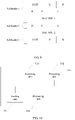
- FIG 12 is a schematic structural diagram of a data processing apparatus according to an embodiment of this application.
- the data processing apparatus 1200 includes a processor 1201 and a memory 1202.
- the processor 1201 invokes a program stored in the memory 1202, to perform all or some of the steps performed by the transmit end or the receive end in the foregoing embodiments, for example, the operations performed at any one of the PDCP layer, the RLC layer, and the MAC layer by the transmit end in the foregoing embodiments, or the operations performed at any one of the PDCP layer, the RLC layer, and the MAC layer by the receive end in the foregoing embodiments.
- FIG 13 is a schematic structural diagram of a terminal according to an embodiment of this application.
- the terminal includes a processor 1301, a memory 1302, and a transceiver apparatus 1303.
- the transceiver apparatus 1303 may be connected to an antenna.
- the transceiver apparatus 1303 receives, by using the antenna, information sent by a RAN device, and sends the information to the processor 1301 for processing.
- the processor 1301 processes data of the terminal, and sends the data to the RAN device by using the transceiver apparatus 1303.
- the terminal When the terminal is a transmit end, the terminal includes any one of the foregoing data processing apparatuses configured to perform the operations of the transmit end, for example, the data processing apparatus shown in FIG 10 or FIG. 12 .
- the units in FIG. 10 may be implemented by using the processor 1301 to invoke program code in the memory 1302, or may be integrated into a chip in the terminal.
- the terminal When the terminal is a receive end, the terminal includes any one of the foregoing data processing apparatuses configured to perform the operations of the receive end, for example, the data processing apparatus shown in FIG 11 or FIG 12 .
- the units in FIG 11 may be implemented by using the processor 1301 to invoke program code in the memory 1302, or may be integrated into a chip in the terminal.
- FIG. 14 is a schematic structural diagram of a RAN device according to an embodiment of this application.
- the RAN device includes an antenna 1410, a radio frequency apparatus 1420, and a baseband apparatus 1430.
- the antenna 1410 is connected to the radio frequency apparatus 1420.
- the radio frequency apparatus 1420 receives, by using the antenna 1410, information sent by a terminal, and sends, to the baseband apparatus 1430 for processing, the information sent by the terminal.
- the baseband apparatus 1430 processes the information of the terminal and sends processed information to the radio frequency apparatus 1420, and the radio frequency apparatus 1420 sends processed information to the terminal by using the antenna 1410 after processing the information of the terminal.
- the RAN device When the RAN device is a transmit end, the RAN device includes any one of the foregoing data processing apparatuses configured to perform the operations of the transmit end, and the data processing apparatus is located in the baseband apparatus 1430.
- the data processing apparatus shown in FIG 10 or FIG 12 may be located in the baseband apparatus 1430.
- the units shown in FIG. 10 are implemented by using a processing element to invoke a program.
- the baseband apparatus 1430 includes a processing element 1431 and a storage element 1432, and the processing element 1431 invokes a program stored in the storage element 1432, to implement the functions of the units.
- the baseband apparatus 1430 may further include an interface 1433, configured to exchange information with the radio frequency apparatus 1420.
- the interface is, for example, a common public radio interface (common public radio interface, CPRI).
- these units may be configured as one or more processing elements, and these processing elements are arranged on the baseband apparatus 1430.
- the processing element herein may be an integrated circuit, for example, one or more ASICs, one or more DSPs, or one or more FPGAs. These integrated circuits may be integrated to form a chip.
- the foregoing units may be integrated together and implemented in the form of a System-On-a-Chip (system-on-a-chip, SOC).
- the baseband apparatus 1430 includes an SOC chip, configured to implement the foregoing units.
- the processing element herein may be a general purpose processor, for example, a central processing unit (Central Processing Unit, CPU), or may be configured as one or more integrated circuits that perform the foregoing methods, for example, one or more ASICs, one or more DSPs, or one or more FPGAs.
- CPU Central Processing Unit
- the storage element may be a memory, or may be a general name for a plurality of storage elements.
- the program may be stored in a computer readable storage medium.
- the foregoing storage medium includes: any medium that can store program code, such as a ROM, a RAM, a magnetic disk, or an optical disc.
- a measurement gap (Measurement Gap) is used to temporarily interrupt communication of a current serving cell when the terminal performs inter-frequency measurement.
- the measurement gap is configured at a granularity of a terminal. After the configuration, the measurement is performed at a granularity of a terminal. That is, when an RAN device configures, for a terminal, a measurement gap parameter, such as a measurement gap period and a measurement gap offset, the terminal does not receive, during a corresponding measurement gap period, information in the current serving cell or at a current serving frequency. However, this affects normal communication between the terminal and the current serving cell. Therefore, an embodiment of this application provides a measurement gap at a granularity of a carrier. However, currently, there is no method for configuring the measurement gap at the granularity of a carrier.
- An embodiment of this application provides a method for configuring a measurement gap parameter.
- the method is used on a RAN device.
- the method is performed by the RAN device.
- the method includes the following steps.
- the RAN device determines a measurement gap configuration parameter.
- the measurement gap configuration parameter includes at least the following:
- the foregoing measurement gap parameter further includes information about one or more serving cells (or information about one or more serving frequencies, or information about one or more serving bands) where information can be received and sent in part of time when the terminal measures one or more measurement frequencies or measurement bands. That information can be received and sent in part of time means that: the terminal can receive and send information in the one or more current serving cells (or at the one or more serving frequencies, or in the one or more serving bands) within a measurement period, except for a time period needed for the terminal to adjust a radio frequency from a frequency corresponding to the information about the one or more current serving cells (or the information about the one or more serving frequencies, or the information about the one or more serving bands) to a frequency at which the one or more measurement frequencies or measurement bands can be measured, and except for a time period needed for the terminal to adjust a radio frequency from a frequency at which the one or more measurement frequencies or measurement bands can be measured to a frequency corresponding to the information about the one or more current serving cells (or the information about the one or more serving frequencies, or the
- the terminal needs to measure a frequency f1 during moments 0 to 5, and the terminal currently works at a frequency of f2. It is assumed that the terminal needs to take 1 ms to adjust a radio frequency from f2 to a frequency at which f1 can be measured, and the terminal needs to take 1 ms to adjust the radio frequency from the frequency at which f1 can be measured back to f2. Therefore, a time during which the terminal can receive and send information at f1 are moments 1 to 4.
- the foregoing measurement gap parameter includes information about one or more serving cells (or information about one or more serving frequencies, or information about one or more serving bands) where information cannot be received and sent in part of time when the terminal measures one or more measurement frequencies or measurement bands.
- the information about the one or more serving cells (or the information about the one or more serving frequencies, or the information about the one or more serving bands) where information can be received and sent in part of time in the foregoing measurement gap is information about all current serving cells (or the information about the one or more serving frequencies, or the information about the one or more serving bands)
- the information about the one or more serving cells may be identified by "all", and the information about all the current serving cells (or the information about the one or more serving frequencies, or the information about the one or more serving bands) is not listed.
- the measurement gap parameter further includes a measurement gap pattern identity (Pattern Identity).
- the measurement gap pattern identity is associated with the foregoing plurality of parameters.
- mapping relationships are shown in Table 1.
- Table 1 Measurement gap pattern 1 (Period: 40 ms; length: 6 ms) Measurement frequency (or band) 1 Information is normally received and sent in a current serving cell 1 (or at a serving frequency 1, or in a serving band 1).
- Measurement gap pattern 2 (Period: 80 ms; length: 6 ms) Measurement frequency (or band) 2 Information is normally received and sent in a current serving cell 1 (or at a serving frequency 1, or in a serving band 1).
- Information is normally received and sent in a current serving cell 2 (or at a serving frequency 2, or in a serving band 2).
- Measurement gap pattern 3 (Period: 40 ms; length: 4 ms) Measurement frequency (or band) 3 Information is normally received and sent in a current serving cell 1 (or at a serving frequency 1, or in a serving band 1) in part of time.
- the RAN device sends the measurement gap configuration parameter to a terminal.
- the measurement gap configuration parameter is included in a radio resource control (Radio Resource Control, RRC) message.
- RRC Radio Resource Control
- an embodiment of this application when the terminal measures different frequencies or bands, information can still be received and sent in the one or more current serving cells. This increases a time of communication between the terminal and the RAN device, and improves a data rate of the terminal.
- an embodiment of this application further provides a RAN device, including units configured to perform the method steps shown in FIG. 15 . Implementation of the units is the same as described in the foregoing embodiments. The units may be implemented by using a processor to invoke a program stored in a memory, or may be integrated into one or more integrated circuits or chips for implementation. In addition, for a structure of the RAN device, refer to FIG 14 .
- Another embodiment of this application provides a method for configuring a measurement gap parameter.
- the method is used on a terminal. In other words, the method is performed by the terminal.
- the method includes the following steps.
- the terminal receives a measurement gap configuration parameter.
- the measurement gap configuration parameter includes at least the following:
- the foregoing measurement gap parameter further includes information about one or more serving cells (or information about one or more serving frequencies, or information about one or more serving bands) where information can be received and sent in part of time when the terminal measures one or more measurement frequencies or measurement bands. That information can be received and sent in part of time means that: the terminal can receive and send information in the one or more current serving cells (or at the one or more serving frequencies, or in the one or more serving bands) within a measurement period, except for a time period needed for the terminal to adjust a radio frequency from a frequency corresponding to the information about the one or more current serving cells (or the information about the one or more serving frequencies, or the information about the one or more serving bands) to a frequency at which the one or more measurement frequencies or measurement bands can be measured, and except for a time period needed for the terminal to adjust a radio frequency from a frequency at which the one or more measurement frequencies or measurement bands can be measured to a frequency corresponding to the information about the one or more current serving cells (or the information about the one or more serving frequencies, or the
- the terminal needs to measure a frequency f1 during moments 0 to 5, and the terminal currently works at a frequency of f2. It is assumed that the terminal needs to take 1 ms to adjust a radio frequency from f2 to a frequency at which f1 can be measured, and the terminal needs to take 1 ms to adjust the radio frequency from the frequency at which f1 can be measured back to f2. Therefore, a time during which the terminal can receive and send information at f1 are moments 1 to 4.
- the foregoing measurement gap parameter includes information about one or more serving cells (or information about one or more serving frequencies, or information about one or more serving bands) where information cannot be received and sent in part of time when the terminal measures one or more measurement frequencies or measurement bands.
- the information about the one or more serving cells (or the information about the one or more serving frequencies, or the information about the one or more serving bands) where information can be received and sent in part of time in the foregoing measurement gap is information about all current serving cells (or the information about the one or more serving frequencies, or the information about the one or more serving bands)
- the information about the one or more serving cells may be identified by "all", and the information about all the current serving cells (or the information about the one or more serving frequencies, or the information about the one or more serving bands) is not listed.
- the measurement gap parameter further includes a measurement gap pattern identity (Pattern Identity).
- the measurement gap pattern identity is associated with the foregoing plurality of parameters.
- Measurement gap pattern 1 (Period: 40 ms; length: 6 ms) Measurement frequency (or band) 1 Information is normally received and sent in a current serving cell 1 (or at a serving frequency 1, or in a serving band 1).
- Measurement gap pattern 2 (Period: 80 ms; length: 6 ms) Measurement frequency (or band) 2 Information is normally received and sent in a current serving cell 1 (or at a serving frequency 1, or in a serving band 1). Information is normally received and sent in a current serving cell 2 (or at a serving frequency 2, or in a serving band 2).
- Measurement gap pattern 3 (Period: 40 ms; length: 4 ms) Measurement frequency (or band) 3 Information is normally received and sent in a current serving cell 1 (or at a serving frequency 1, or in a serving band 1) in part of time.
- the measurement gap configuration parameter is included in a radio resource control (Radio Resource Control, RRC) message.
- RRC Radio Resource Control
- the terminal performs measurement by using the measurement gap configuration parameter.
- an embodiment of this application when the terminal measures different frequencies or bands, information can still be received and sent on the one or more current serving cells. This increases a time of communication between the terminal and the RAN device, and improves a data rate of the terminal.
- an embodiment of this application further provides a terminal, including units configured to perform the method steps shown in FIG. 16 . Implementation of the units is the same as described in the foregoing embodiments. The units may be implemented by using a processor to invoke a program stored in a memory, or may be integrated into one or more integrated circuits or chips for implementation. In addition, for a structure of the terminal, refer to FIG. 13 .
Landscapes
- Engineering & Computer Science (AREA)
- Signal Processing (AREA)
- Computer Networks & Wireless Communication (AREA)
- Computer Security & Cryptography (AREA)
- Mobile Radio Communication Systems (AREA)
- Communication Control (AREA)
Applications Claiming Priority (3)
| Application Number | Priority Date | Filing Date | Title |
|---|---|---|---|
| CN201610873599.9A CN107889163B (zh) | 2016-09-30 | 2016-09-30 | 数据处理方法、装置及系统 |
| EP17855040.6A EP3474595B1 (fr) | 2016-09-30 | 2017-09-30 | Procédés et dispositifs de traitement de données |
| PCT/CN2017/105044 WO2018059590A1 (fr) | 2016-09-30 | 2017-09-30 | Procédé, dispositif et système de traitement de données |
Related Parent Applications (1)
| Application Number | Title | Priority Date | Filing Date |
|---|---|---|---|
| EP17855040.6A Division EP3474595B1 (fr) | 2016-09-30 | 2017-09-30 | Procédés et dispositifs de traitement de données |
Publications (1)
| Publication Number | Publication Date |
|---|---|
| EP4013113A1 true EP4013113A1 (fr) | 2022-06-15 |
Family
ID=61763302
Family Applications (2)
| Application Number | Title | Priority Date | Filing Date |
|---|---|---|---|
| EP21203077.9A Pending EP4013113A1 (fr) | 2016-09-30 | 2017-09-30 | Procédé et appareil de traitement de données |
| EP17855040.6A Active EP3474595B1 (fr) | 2016-09-30 | 2017-09-30 | Procédés et dispositifs de traitement de données |
Family Applications After (1)
| Application Number | Title | Priority Date | Filing Date |
|---|---|---|---|
| EP17855040.6A Active EP3474595B1 (fr) | 2016-09-30 | 2017-09-30 | Procédés et dispositifs de traitement de données |
Country Status (9)
| Country | Link |
|---|---|
| US (2) | US10999890B2 (fr) |
| EP (2) | EP4013113A1 (fr) |
| JP (1) | JP6827533B2 (fr) |
| KR (1) | KR102208262B1 (fr) |
| CN (3) | CN107889163B (fr) |
| AU (1) | AU2017337009B2 (fr) |
| ES (1) | ES2899957T3 (fr) |
| RU (1) | RU2756289C2 (fr) |
| WO (1) | WO2018059590A1 (fr) |
Families Citing this family (26)
| Publication number | Priority date | Publication date | Assignee | Title |
|---|---|---|---|---|
| EP3319252A1 (fr) | 2016-11-04 | 2018-05-09 | Panasonic Intellectual Property Corporation of America | Multiplexage efficace d'informations de commande dans un bloc de transport |
| KR102464567B1 (ko) * | 2017-01-16 | 2022-11-09 | 삼성전자 주식회사 | 무선 통신 시스템에서 데이터 처리 방법 및 장치 |
| JP6858263B2 (ja) * | 2017-02-03 | 2021-04-14 | テレフオンアクチーボラゲット エルエム エリクソン(パブル) | メッセージの送信の遅延 |
| CN108809542B (zh) * | 2017-05-05 | 2021-04-20 | 华为技术有限公司 | 一种数据传输的处理方法和装置 |
| CA3063947C (fr) * | 2017-05-19 | 2023-01-24 | Guangdong Oppo Mobile Telecommunications Corp., Ltd. | Procede et dispositif de transmission de donnees |
| CN110679105B (zh) * | 2017-05-24 | 2024-02-06 | Oppo广东移动通信有限公司 | 无线链路控制传输方法及相关产品 |
| WO2018227501A1 (fr) * | 2017-06-15 | 2018-12-20 | Oppo广东移动通信有限公司 | Procédé et dispositif de transmission de données |
| WO2019023862A1 (fr) * | 2017-07-31 | 2019-02-07 | Oppo广东移动通信有限公司 | Procédé de traitement de données et produit associé à celui-ci |
| CN110365609B (zh) * | 2018-04-10 | 2021-12-14 | 华为技术有限公司 | 一种数据包分段方法、及装置 |
| CN108933645B (zh) * | 2018-06-04 | 2021-07-23 | 熊猫电子集团有限公司 | 一种终端高效主动轮询方法 |
| WO2019233056A1 (fr) * | 2018-06-07 | 2019-12-12 | 华为技术有限公司 | Procédé de réception de données de liaison descendante et dispositif terminal |
| GB2576204B (en) * | 2018-07-27 | 2021-02-17 | Samsung Electronics Co Ltd | Operation of automatic repeat request (ARQ) |
| WO2020022849A1 (fr) | 2018-07-27 | 2020-01-30 | Samsung Electronics Co., Ltd. | Procédé et appareil destinés à une communication sans fil d'un nœud sans fil dans un système de communication sans fil |
| CN110830421B (zh) * | 2018-08-10 | 2022-07-29 | 华为技术有限公司 | 数据传输方法和设备 |
| CN109688606B (zh) * | 2018-12-29 | 2022-03-25 | 京信网络系统股份有限公司 | 数据处理方法、装置、计算机设备及存储介质 |
| CN111586803B (zh) * | 2019-02-15 | 2021-09-07 | 华为技术有限公司 | 一种通信方法及相关设备 |
| US11088871B1 (en) * | 2019-12-31 | 2021-08-10 | Juniper Networks, Inc. | Fast convergence for MAC mobility |
| CN111132232B (zh) * | 2020-01-02 | 2022-10-25 | 重庆邮电大学 | 一种智能接收5g nr rlc umd pdu的方法和装置 |
| CN113543040B (zh) * | 2020-04-22 | 2023-04-07 | 维沃移动通信有限公司 | 数据处理方法、数据处理装置及通信设备 |
| CN114270742B (zh) * | 2020-04-30 | 2024-03-26 | 华为技术有限公司 | 处理数据包的方法和通信装置 |
| GB2595638B (en) * | 2020-05-20 | 2023-07-26 | Canon Kk | Method for PDCP network coding in 5G-Ran or 4G E-Utran |
| CN114500671B (zh) * | 2020-10-27 | 2024-05-07 | 中国移动通信有限公司研究院 | 数据处理方法及设备 |
| KR20220132932A (ko) * | 2021-03-24 | 2022-10-04 | 삼성전자주식회사 | 차세대 이동 통신 시스템에서 데이터 처리를 가속화하는 데이터 분할 방법과 수신 상태 보고 방법 및 장치 |
| CN116506971A (zh) * | 2022-01-18 | 2023-07-28 | 中国移动通信有限公司研究院 | Mac pdu发送方法、接收方法及通信设备 |
| CN114513812A (zh) * | 2022-02-24 | 2022-05-17 | 上海中兴易联通讯股份有限公司 | 一种提高5g nr组包效率的方法和装置 |
| US12177721B2 (en) * | 2022-03-10 | 2024-12-24 | Qualcomm Incorporated | Protocol overhead reduction for medium access control |
Citations (2)
| Publication number | Priority date | Publication date | Assignee | Title |
|---|---|---|---|---|
| EP2141937A1 (fr) * | 2007-04-26 | 2010-01-06 | Fujitsu Limited | Station de base, station mobile, système de communication, procédé de transmission et procédé de réordonnancement |
| WO2016080877A1 (fr) * | 2014-11-20 | 2016-05-26 | Telefonaktiebolaget L M Ericsson (Publ) | Premier nœud de réseau, second nœud de réseau et procédés d'émission et de réception d'une unité de données de protocole |
Family Cites Families (33)
| Publication number | Priority date | Publication date | Assignee | Title |
|---|---|---|---|---|
| US6788944B2 (en) * | 2001-04-02 | 2004-09-07 | Asustek Computer Inc. | Length indicator for a protocol data unit in a wireless communications protocol |
| KR20050095419A (ko) * | 2004-03-26 | 2005-09-29 | 삼성전자주식회사 | 패킷 망을 이용하여 음성 서비스를 제공하는이동통신시스템에서 무선 자원을 효율적으로 사용하는 방법 |
| KR100913900B1 (ko) | 2005-05-04 | 2009-08-26 | 삼성전자주식회사 | 이동통신 시스템에서 미리 정의된 길이 지시자를 이용해서 패킷 데이터를 송수신하는 방법 및 장치 |
| DE602005010252D1 (de) * | 2005-09-20 | 2008-11-20 | Matsushita Electric Ind Co Ltd | Vefahren und Vorrichtung zur Packetsegmentierung und Verknüpfungssignalisierung in einem Kommunikationssystem |
| TW200742356A (en) * | 2006-04-27 | 2007-11-01 | Asustek Comp Inc | Method and apparatus for handling segmentation and numbering of SDU in wireless communications system |
| US20080130684A1 (en) * | 2006-12-05 | 2008-06-05 | Sam Shiaw-Shiang Jiang | Method and apparatus for performing reordering in a wireless communications system |
| WO2008073043A2 (fr) * | 2006-12-15 | 2008-06-19 | Telefonaktiebolaget Lm Ericsson (Publ) | Indicateur de segmentation monobit |
| TWI521927B (zh) | 2007-01-09 | 2016-02-11 | 皇家飛利浦電子股份有限公司 | 無線通信系統 |
| CN101222484A (zh) | 2007-01-09 | 2008-07-16 | 中兴通讯股份有限公司 | 一种无线链路控制层协议数据单元的实现方法 |
| US7817669B2 (en) * | 2007-02-01 | 2010-10-19 | Interdigital Technology Corporation | Method and apparatus for supporting RLC re-segmentation |
| US8503423B2 (en) * | 2007-02-02 | 2013-08-06 | Interdigital Technology Corporation | Method and apparatus for versatile MAC multiplexing in evolved HSPA |
| US20080226074A1 (en) | 2007-03-15 | 2008-09-18 | Interdigital Technology Corporation | Method and apparatus for ciphering packet units in wireless communications |
| KR101435832B1 (ko) * | 2007-03-19 | 2014-08-29 | 엘지전자 주식회사 | 이동통신 시스템에서의 무선 프로토콜 처리방법 및이동통신 송신기 |
| US8331399B2 (en) * | 2007-05-07 | 2012-12-11 | Qualcomm Incorporated | Re-using sequence number by multiple protocols for wireless communication |
| US20080310452A1 (en) * | 2007-06-14 | 2008-12-18 | Texas Instruments Incorporated | Data link layer headers |
| CN101364990B (zh) * | 2007-08-08 | 2012-06-27 | 华为技术有限公司 | 一种减少数据头开销的方法 |
| JP4521430B2 (ja) * | 2007-08-10 | 2010-08-11 | 富士通株式会社 | 無線送信装置、無線受信装置、無線送信方法、および無線受信方法 |
| US8315243B2 (en) | 2007-08-14 | 2012-11-20 | Qualcomm Incorporated | Transport of PDCP control PDUs within MAC frames |
| CN101370165A (zh) * | 2007-08-17 | 2009-02-18 | 中兴通讯股份有限公司 | 一种多媒体广播业务中数据包的传输方法 |
| RU2465737C2 (ru) * | 2008-01-04 | 2012-10-27 | Нокиа Корпорейшн | Фиктивный дополняющий подзаголовок в блоках данных протокола уровня доступа к среде |
| KR101565403B1 (ko) | 2008-01-07 | 2015-11-03 | 엘지전자 주식회사 | Hspa를 이용하여 수신한 회선 교환 데이터의 오류 제어방법 |
| CN101483505B (zh) * | 2008-01-08 | 2013-02-27 | 中兴通讯股份有限公司 | 一种服务数据单元丢弃方法 |
| KR20090084320A (ko) * | 2008-01-31 | 2009-08-05 | 삼성전자주식회사 | 이동 통신 시스템에서 매체 접속 제어 프로토콜 데이터유닛을 송수신하는 장치 및 방법 |
| US8958411B2 (en) | 2008-03-17 | 2015-02-17 | Lg Electronics Inc. | Method of transmitting RLC data |
| CN101883389B (zh) * | 2009-05-07 | 2013-07-10 | 电信科学技术研究院 | 一种指示rlc sdu长度的方法和装置 |
| CN102104535B (zh) * | 2009-12-18 | 2013-12-18 | 华为技术有限公司 | 一种pdcp数据发送方法、装置及系统 |
| KR101638195B1 (ko) * | 2010-02-01 | 2016-07-08 | 삼성전자주식회사 | 통신 시스템에서 무선 링크 제어 계층 및 패킷 데이터 융합 프로토콜 계층 간의 플로우 제어를 위한 방법 및 장치 |
| EP2688334B1 (fr) | 2012-07-17 | 2018-10-03 | LG Electronics Inc. | Procédé et appareil pour mesurer le débit d'une rafale de données dans un système de communication sans fil |
| US10004098B2 (en) * | 2014-01-29 | 2018-06-19 | Samsung Electronics Co., Ltd. | Method and apparatus for transmitting and receiving data using a plurality of carriers in mobile communication system |
| CN107071913B (zh) * | 2014-09-18 | 2020-04-21 | 株式会社Kt | 用于处理用户平面数据的方法及装置 |
| US20160308776A1 (en) | 2015-04-20 | 2016-10-20 | Qualcomm Incorporated | Enhancements for pdcp layer |
| WO2017051076A1 (fr) | 2015-09-25 | 2017-03-30 | Nokia Solutions And Networks Oy | Amélioration d'un rapport d'état pdcp |
| US10484129B2 (en) * | 2016-01-21 | 2019-11-19 | Qualcomm Incorporated | Protocol layer packet coding for transmitter/receiver buffer optimization |
-
2016
- 2016-09-30 CN CN201610873599.9A patent/CN107889163B/zh active Active
- 2016-09-30 CN CN201910643602.1A patent/CN110505656B/zh active Active
-
2017
- 2017-09-30 CN CN201780060896.4A patent/CN109792634B/zh active Active
- 2017-09-30 AU AU2017337009A patent/AU2017337009B2/en active Active
- 2017-09-30 EP EP21203077.9A patent/EP4013113A1/fr active Pending
- 2017-09-30 KR KR1020197010628A patent/KR102208262B1/ko active IP Right Grant
- 2017-09-30 EP EP17855040.6A patent/EP3474595B1/fr active Active
- 2017-09-30 WO PCT/CN2017/105044 patent/WO2018059590A1/fr unknown
- 2017-09-30 JP JP2019517221A patent/JP6827533B2/ja active Active
- 2017-09-30 RU RU2019112746A patent/RU2756289C2/ru active
- 2017-09-30 ES ES17855040T patent/ES2899957T3/es active Active
-
2019
- 2019-04-01 US US16/371,903 patent/US10999890B2/en active Active
- 2019-06-07 US US16/434,879 patent/US20190297667A1/en not_active Abandoned
Patent Citations (2)
| Publication number | Priority date | Publication date | Assignee | Title |
|---|---|---|---|---|
| EP2141937A1 (fr) * | 2007-04-26 | 2010-01-06 | Fujitsu Limited | Station de base, station mobile, système de communication, procédé de transmission et procédé de réordonnancement |
| WO2016080877A1 (fr) * | 2014-11-20 | 2016-05-26 | Telefonaktiebolaget L M Ericsson (Publ) | Premier nœud de réseau, second nœud de réseau et procédés d'émission et de réception d'une unité de données de protocole |
Non-Patent Citations (1)
| Title |
|---|
| TEXAS INSTRUMENTS INC: "PDCP-RLC-MAC Header Formats", 3GPP DRAFT; R2-072511_PDCP_RLC-MAC_HEADER_FORMAT_TEXAS_INSTRUMENTS, 3RD GENERATION PARTNERSHIP PROJECT (3GPP), MOBILE COMPETENCE CENTRE ; 650, ROUTE DES LUCIOLES ; F-06921 SOPHIA-ANTIPOLIS CEDEX ; FRANCE, vol. RAN WG2, no. Orlando, Florida, USA; 20070625 - 20070629, 22 June 2007 (2007-06-22), XP050603096 * |
Also Published As
| Publication number | Publication date |
|---|---|
| CN107889163B (zh) | 2022-10-18 |
| RU2019112746A3 (fr) | 2021-01-15 |
| US10999890B2 (en) | 2021-05-04 |
| RU2756289C2 (ru) | 2021-09-29 |
| CN109792634B (zh) | 2023-04-18 |
| WO2018059590A1 (fr) | 2018-04-05 |
| AU2017337009A1 (en) | 2019-04-11 |
| EP3474595A1 (fr) | 2019-04-24 |
| CN109792634A (zh) | 2019-05-21 |
| JP6827533B2 (ja) | 2021-02-10 |
| US20190297667A1 (en) | 2019-09-26 |
| CN107889163A (zh) | 2018-04-06 |
| EP3474595A4 (fr) | 2019-05-01 |
| CN110505656B (zh) | 2020-07-24 |
| CN110505656A (zh) | 2019-11-26 |
| JP2019537308A (ja) | 2019-12-19 |
| KR20190052081A (ko) | 2019-05-15 |
| RU2019112746A (ru) | 2020-10-30 |
| US20190230736A1 (en) | 2019-07-25 |
| AU2017337009B2 (en) | 2020-12-17 |
| ES2899957T3 (es) | 2022-03-15 |
| EP3474595B1 (fr) | 2021-11-03 |
| KR102208262B1 (ko) | 2021-01-26 |
Similar Documents
| Publication | Publication Date | Title |
|---|---|---|
| US10999890B2 (en) | Data processing method, apparatus, and system | |
| CN110603896B (zh) | 新型无线电接入技术中的pdcp重复和数据恢复的处理 | |
| KR101211758B1 (ko) | 무선 통신 시스템의 블록 데이터 생성 방법 | |
| EP3520561B1 (fr) | Architecture efficace de plan utilisateur | |
| EP4149157A2 (fr) | Procédé et appareil de communication sans fil dans un système de communication sans fil | |
| EP3737183B1 (fr) | Procédés et dispositifs de communication et support de stockage lisible par ordinateur | |
| US20210352743A1 (en) | Communication method and apparatus | |
| EP3445020B1 (fr) | Procédé et appareil permettant d'exécuter une fonction de couche 2 efficace dans un système de communications mobiles | |
| EP4380082A1 (fr) | Procédé et appareil de communication sans fil | |
| WO2022203581A1 (fr) | Procédés et appareil pour processus harq désactivés | |
| EP4068844A1 (fr) | Fonctionnement de tampon de couche 2 d'équipement utilisateur dans des réseaux iab | |
| WO2020163849A1 (fr) | Système de communication à mac unique et à multiples bandes | |
| EP4082295B1 (fr) | Alignement et décodage de protocole de liaison descendante | |
| US12004144B2 (en) | Multi-band single mac communication system | |
| CN115915253A (zh) | 一种通信方法及装置 | |
| CN118869622A (zh) | 数据传输的方法及装置、芯片以及通信设备 | |
| CN116801253A (zh) | 一种通信方法和装置 |
Legal Events
| Date | Code | Title | Description |
|---|---|---|---|
| PUAI | Public reference made under article 153(3) epc to a published international application that has entered the european phase |
Free format text: ORIGINAL CODE: 0009012 |
|
| STAA | Information on the status of an ep patent application or granted ep patent |
Free format text: STATUS: REQUEST FOR EXAMINATION WAS MADE |
|
| 17P | Request for examination filed |
Effective date: 20211018 |
|
| AC | Divisional application: reference to earlier application |
Ref document number: 3474595 Country of ref document: EP Kind code of ref document: P |
|
| AK | Designated contracting states |
Kind code of ref document: A1 Designated state(s): AL AT BE BG CH CY CZ DE DK EE ES FI FR GB GR HR HU IE IS IT LI LT LU LV MC MK MT NL NO PL PT RO RS SE SI SK SM TR |
|
| STAA | Information on the status of an ep patent application or granted ep patent |
Free format text: STATUS: EXAMINATION IS IN PROGRESS |
|
| 17Q | First examination report despatched |
Effective date: 20240618 |
|
| 17Q | First examination report despatched |
Effective date: 20240626 |