EP3932450A1 - Liquid medicine administration apparatus - Google Patents
Liquid medicine administration apparatus Download PDFInfo
- Publication number
- EP3932450A1 EP3932450A1 EP20784086.9A EP20784086A EP3932450A1 EP 3932450 A1 EP3932450 A1 EP 3932450A1 EP 20784086 A EP20784086 A EP 20784086A EP 3932450 A1 EP3932450 A1 EP 3932450A1
- Authority
- EP
- European Patent Office
- Prior art keywords
- liquid medicine
- motor
- plunger
- control unit
- administration
- Prior art date
- Legal status (The legal status is an assumption and is not a legal conclusion. Google has not performed a legal analysis and makes no representation as to the accuracy of the status listed.)
- Withdrawn
Links
- 239000003814 drug Substances 0.000 title claims abstract description 220
- 239000007788 liquid Substances 0.000 title claims abstract description 220
- 230000005856 abnormality Effects 0.000 claims abstract description 31
- 238000001514 detection method Methods 0.000 claims abstract description 25
- 238000005259 measurement Methods 0.000 claims description 3
- 238000010586 diagram Methods 0.000 description 10
- 230000004308 accommodation Effects 0.000 description 6
- 230000007423 decrease Effects 0.000 description 5
- 238000000034 method Methods 0.000 description 5
- 229940079593 drug Drugs 0.000 description 2
- 229920001971 elastomer Polymers 0.000 description 2
- 239000000463 material Substances 0.000 description 2
- 230000003287 optical effect Effects 0.000 description 2
- 230000001681 protective effect Effects 0.000 description 2
- 239000011347 resin Substances 0.000 description 2
- 229920005989 resin Polymers 0.000 description 2
- 238000007789 sealing Methods 0.000 description 2
- 210000001015 abdomen Anatomy 0.000 description 1
- 229940035676 analgesics Drugs 0.000 description 1
- 239000000730 antalgic agent Substances 0.000 description 1
- 230000000903 blocking effect Effects 0.000 description 1
- 239000002934 diuretic Substances 0.000 description 1
- 229940030606 diuretics Drugs 0.000 description 1
- 230000000694 effects Effects 0.000 description 1
- 239000000806 elastomer Substances 0.000 description 1
- 238000012840 feeding operation Methods 0.000 description 1
- 239000002184 metal Substances 0.000 description 1
- 230000003533 narcotic effect Effects 0.000 description 1
- 238000002360 preparation method Methods 0.000 description 1
- 238000003825 pressing Methods 0.000 description 1
- 102000004169 proteins and genes Human genes 0.000 description 1
- 108090000623 proteins and genes Proteins 0.000 description 1
Images


Classifications
-
- A—HUMAN NECESSITIES
- A61—MEDICAL OR VETERINARY SCIENCE; HYGIENE
- A61M—DEVICES FOR INTRODUCING MEDIA INTO, OR ONTO, THE BODY; DEVICES FOR TRANSDUCING BODY MEDIA OR FOR TAKING MEDIA FROM THE BODY; DEVICES FOR PRODUCING OR ENDING SLEEP OR STUPOR
- A61M5/00—Devices for bringing media into the body in a subcutaneous, intra-vascular or intramuscular way; Accessories therefor, e.g. filling or cleaning devices, arm-rests
- A61M5/14—Infusion devices, e.g. infusing by gravity; Blood infusion; Accessories therefor
- A61M5/142—Pressure infusion, e.g. using pumps
- A61M5/145—Pressure infusion, e.g. using pumps using pressurised reservoirs, e.g. pressurised by means of pistons
-
- A—HUMAN NECESSITIES
- A61—MEDICAL OR VETERINARY SCIENCE; HYGIENE
- A61M—DEVICES FOR INTRODUCING MEDIA INTO, OR ONTO, THE BODY; DEVICES FOR TRANSDUCING BODY MEDIA OR FOR TAKING MEDIA FROM THE BODY; DEVICES FOR PRODUCING OR ENDING SLEEP OR STUPOR
- A61M5/00—Devices for bringing media into the body in a subcutaneous, intra-vascular or intramuscular way; Accessories therefor, e.g. filling or cleaning devices, arm-rests
- A61M5/14—Infusion devices, e.g. infusing by gravity; Blood infusion; Accessories therefor
- A61M5/168—Means for controlling media flow to the body or for metering media to the body, e.g. drip meters, counters ; Monitoring media flow to the body
- A61M5/16831—Monitoring, detecting, signalling or eliminating infusion flow anomalies
-
- A—HUMAN NECESSITIES
- A61—MEDICAL OR VETERINARY SCIENCE; HYGIENE
- A61M—DEVICES FOR INTRODUCING MEDIA INTO, OR ONTO, THE BODY; DEVICES FOR TRANSDUCING BODY MEDIA OR FOR TAKING MEDIA FROM THE BODY; DEVICES FOR PRODUCING OR ENDING SLEEP OR STUPOR
- A61M5/00—Devices for bringing media into the body in a subcutaneous, intra-vascular or intramuscular way; Accessories therefor, e.g. filling or cleaning devices, arm-rests
- A61M5/14—Infusion devices, e.g. infusing by gravity; Blood infusion; Accessories therefor
- A61M5/142—Pressure infusion, e.g. using pumps
- A61M5/14244—Pressure infusion, e.g. using pumps adapted to be carried by the patient, e.g. portable on the body
- A61M5/14248—Pressure infusion, e.g. using pumps adapted to be carried by the patient, e.g. portable on the body of the skin patch type
- A61M2005/14252—Pressure infusion, e.g. using pumps adapted to be carried by the patient, e.g. portable on the body of the skin patch type with needle insertion means
-
- A—HUMAN NECESSITIES
- A61—MEDICAL OR VETERINARY SCIENCE; HYGIENE
- A61M—DEVICES FOR INTRODUCING MEDIA INTO, OR ONTO, THE BODY; DEVICES FOR TRANSDUCING BODY MEDIA OR FOR TAKING MEDIA FROM THE BODY; DEVICES FOR PRODUCING OR ENDING SLEEP OR STUPOR
- A61M5/00—Devices for bringing media into the body in a subcutaneous, intra-vascular or intramuscular way; Accessories therefor, e.g. filling or cleaning devices, arm-rests
- A61M5/14—Infusion devices, e.g. infusing by gravity; Blood infusion; Accessories therefor
- A61M5/168—Means for controlling media flow to the body or for metering media to the body, e.g. drip meters, counters ; Monitoring media flow to the body
- A61M5/16831—Monitoring, detecting, signalling or eliminating infusion flow anomalies
- A61M2005/16863—Occlusion detection
-
- A—HUMAN NECESSITIES
- A61—MEDICAL OR VETERINARY SCIENCE; HYGIENE
- A61M—DEVICES FOR INTRODUCING MEDIA INTO, OR ONTO, THE BODY; DEVICES FOR TRANSDUCING BODY MEDIA OR FOR TAKING MEDIA FROM THE BODY; DEVICES FOR PRODUCING OR ENDING SLEEP OR STUPOR
- A61M2205/00—General characteristics of the apparatus
- A61M2205/10—General characteristics of the apparatus with powered movement mechanisms
-
- A—HUMAN NECESSITIES
- A61—MEDICAL OR VETERINARY SCIENCE; HYGIENE
- A61M—DEVICES FOR INTRODUCING MEDIA INTO, OR ONTO, THE BODY; DEVICES FOR TRANSDUCING BODY MEDIA OR FOR TAKING MEDIA FROM THE BODY; DEVICES FOR PRODUCING OR ENDING SLEEP OR STUPOR
- A61M2205/00—General characteristics of the apparatus
- A61M2205/33—Controlling, regulating or measuring
- A61M2205/3365—Rotational speed
-
- A—HUMAN NECESSITIES
- A61—MEDICAL OR VETERINARY SCIENCE; HYGIENE
- A61M—DEVICES FOR INTRODUCING MEDIA INTO, OR ONTO, THE BODY; DEVICES FOR TRANSDUCING BODY MEDIA OR FOR TAKING MEDIA FROM THE BODY; DEVICES FOR PRODUCING OR ENDING SLEEP OR STUPOR
- A61M2205/00—General characteristics of the apparatus
- A61M2205/50—General characteristics of the apparatus with microprocessors or computers
-
- A—HUMAN NECESSITIES
- A61—MEDICAL OR VETERINARY SCIENCE; HYGIENE
- A61M—DEVICES FOR INTRODUCING MEDIA INTO, OR ONTO, THE BODY; DEVICES FOR TRANSDUCING BODY MEDIA OR FOR TAKING MEDIA FROM THE BODY; DEVICES FOR PRODUCING OR ENDING SLEEP OR STUPOR
- A61M2205/00—General characteristics of the apparatus
- A61M2205/58—Means for facilitating use, e.g. by people with impaired vision
- A61M2205/581—Means for facilitating use, e.g. by people with impaired vision by audible feedback
-
- A—HUMAN NECESSITIES
- A61—MEDICAL OR VETERINARY SCIENCE; HYGIENE
- A61M—DEVICES FOR INTRODUCING MEDIA INTO, OR ONTO, THE BODY; DEVICES FOR TRANSDUCING BODY MEDIA OR FOR TAKING MEDIA FROM THE BODY; DEVICES FOR PRODUCING OR ENDING SLEEP OR STUPOR
- A61M2205/00—General characteristics of the apparatus
- A61M2205/58—Means for facilitating use, e.g. by people with impaired vision
- A61M2205/583—Means for facilitating use, e.g. by people with impaired vision by visual feedback
-
- A—HUMAN NECESSITIES
- A61—MEDICAL OR VETERINARY SCIENCE; HYGIENE
- A61M—DEVICES FOR INTRODUCING MEDIA INTO, OR ONTO, THE BODY; DEVICES FOR TRANSDUCING BODY MEDIA OR FOR TAKING MEDIA FROM THE BODY; DEVICES FOR PRODUCING OR ENDING SLEEP OR STUPOR
- A61M5/00—Devices for bringing media into the body in a subcutaneous, intra-vascular or intramuscular way; Accessories therefor, e.g. filling or cleaning devices, arm-rests
- A61M5/14—Infusion devices, e.g. infusing by gravity; Blood infusion; Accessories therefor
- A61M5/142—Pressure infusion, e.g. using pumps
- A61M5/145—Pressure infusion, e.g. using pumps using pressurised reservoirs, e.g. pressurised by means of pistons
- A61M5/1452—Pressure infusion, e.g. using pumps using pressurised reservoirs, e.g. pressurised by means of pistons pressurised by means of pistons
Definitions
- the present invention relates to a liquid medicine administration device capable of detecting an abnormality in administration of a liquid medicine.
- Patent Literature 1 there is known a syringe pump type liquid medicine administration device that administers a liquid medicine filled in a liquid medicine container to a living body.
- the syringe pump type liquid medicine administration device includes a drive mechanism and a control unit, and continuously administers a liquid medicine with high accuracy for a long time by moving a plunger little by little by the drive mechanism.
- Patent Literature 1 JP 2015-181869 A
- the control unit drives the drive mechanism, and moves the plunger little by little to administer the liquid medicine to the living body.
- the liquid medicine leaks from the middle of the supply path since pressure of the plunger cannot be withstood, and the liquid medicine administration device itself is damaged since the drive mechanism or the motor is overloaded.
- the load on the motor decreases, and thus the abnormality in administration cannot be detected even when it is detected whether or not the motor is rotating.
- An object of the present invention is to provide a liquid medicine administration device capable of detecting an abnormality in administration of a liquid medicine.
- an aspect of the present invention provides a liquid medicine administration device including: a plunger that pushes a liquid medicine in a liquid medicine container filled with the liquid medicine; a supply path that causes a distal end opening of the liquid medicine container to communicate with a needle in order to administer the liquid medicine from the needle pierced into a living body; a drive mechanism that advances the plunger toward the distal end opening of the liquid medicine container in order to discharge the liquid medicine from the liquid medicine container; and a control unit that controls operation of the drive mechanism, in which the drive mechanism includes a DC motor that applies, to the plunger, a drive force for advancing the plunger, and a rotation detection unit that detects a rotation of the DC motor, and the control unit has a rotation speed calculation function of calculating a rotation speed of the DC motor based on the rotation of the DC motor detected by the rotation detection unit, and detects an abnormality in administration when the rotation speed of the DC motor calculated by the rotation speed calculation function is lower than a predetermined lower limit rotation speed
- a liquid medicine administration device including: a plunger that pushes a liquid medicine in a liquid medicine container filled with the liquid medicine; a supply path that causes a distal end opening of the liquid medicine container to communicate with a needle in order to administer the liquid medicine from the needle pierced into a living body; a drive mechanism that advances the plunger toward the distal end opening of the liquid medicine container in order to discharge the liquid medicine from the liquid medicine container; and a control unit that controls operation of the drive mechanism, in which the drive mechanism includes a DC motor that applies, to the plunger, a drive force for advancing the plunger, and the control unit has a current value measurement function of measuring a value of a motor current flowing in the DC motor, and detects an abnormality in administration when the value of the motor current exceeds a predetermined upper limit current value.
- a liquid medicine administration device including: a plunger that pushes a liquid medicine in a liquid medicine container filled with the liquid medicine; a supply path that causes a distal end opening of the liquid medicine container to communicate with a needle in order to administer the liquid medicine from the needle pierced into a living body; a drive mechanism that advances the plunger toward the distal end opening of the liquid medicine container in order to discharge the liquid medicine from the liquid medicine container and includes a DC motor that applies, to the plunger, a drive force for advancing the plunger; a control unit that controls operation of the drive mechanism; and a current limiting circuit that limits a current so that any current equal to or greater than a predetermined current does not flow in the DC motor.
- the liquid medicine administration device since the abnormality in administration of the liquid medicine can be detected, it is possible to prevent the liquid medicine from leaking out or the liquid medicine administration device from being damaged.
- Figs. 1 to 6 are views for explaining a liquid medicine administration system 10, a liquid medicine administration device 100, and an administration tool 200 according to the present embodiment.
- Fig. 1 is a side view of a liquid medicine administration system.
- Fig. 2 is a view schematically illustrating a usage example of the liquid medicine administration system.
- Fig. 3 is a schematic perspective view of a liquid medicine administration device.
- Fig. 4 is a schematic perspective view of a chassis included in a housing and each component member assembled to the chassis.
- Fig. 5 is a plan view of the liquid medicine administration device illustrating a state before a plunger is moved forward.
- Fig. 6 is a plan view of the liquid medicine administration device illustrating a state after the plunger is moved forward.
- an arrow X in each drawing indicates a "longitudinal direction (longitudinal direction of a liquid medicine container 110)" of the liquid medicine administration device 100
- an arrow Y indicates a "width direction (depth direction)” of the liquid medicine administration device 100
- an arrow Z indicates a "height direction” of the liquid medicine administration device 100.
- the liquid medicine administration system 10 is used to administer a liquid medicine into a living body. As illustrated in Fig. 1 , the liquid medicine administration system 10 includes the liquid medicine administration device 100 and the administration tool 200.
- the liquid medicine administration device 100 and the administration tool 200 are configured as a patch type used by being stuck on a body surface (skin) H of a user.
- a body part of the user to which the liquid medicine administration device 100 and the administration tool 200 are attached is not particularly limited, but is, for example, an abdomen or a femoral part.
- the liquid medicine administration system 10 can continuously administer a liquid medicine (not illustrated) filled in the liquid medicine container 110 included in the liquid medicine administration device 100 into the living body for a relatively long time (for example, approximately several minutes to several hours) by a pressing action of a plunger 130 (see Fig. 4 ) to be described later.
- the liquid medicine administration system 10 may intermittently administer the liquid medicine into the living body.
- the liquid medicine administration device 100 includes the liquid medicine container 110 including a cylindrical (barrel-shaped) main body 111 filled with the liquid medicine, a housing 120 that holds the liquid medicine container 110, the plunger 130 that pushes the liquid medicine in the liquid medicine container 110, a drive mechanism 140 that advances the plunger 130 toward a distal end opening of the liquid medicine container 110, a detection unit 150 that detects a portion 134 to be detected of the plunger 130 and detects completion of feeding of the liquid medicine based on a detection result, and a control unit 160 that controls operation of the drive mechanism 140.
- the liquid medicine container 110 including a cylindrical (barrel-shaped) main body 111 filled with the liquid medicine
- a housing 120 that holds the liquid medicine container 110
- the plunger 130 that pushes the liquid medicine in the liquid medicine container 110
- a drive mechanism 140 that advances the plunger 130 toward a distal end opening of the liquid medicine container 110
- a detection unit 150 that detects a portion 134 to be detected of the plunger 130 and detects completion
- the housing 120 includes a box-shaped housing main body 120a in which an accommodation space 128 is formed, and a chassis (corresponding to a "support portion") 127 which is accommodated in the accommodation space 128 of the housing main body 120a and can be fixed to the housing main body 120a.
- a window portion 123a that allows the inside of the accommodation space 128 to be visually recognized from the outside of the housing 120 is formed on an upper surface 123 of the housing main body 120a.
- the window portion 123a is formed by providing a transparent or translucent portion in a part of the housing main body 120a.
- a proximal end opening 125 for inserting a chassis 127 into the accommodation space 128 of the housing main body 120a is formed on a proximal end side in a longitudinal direction of the housing main body 120a.
- the proximal end opening 125 of the housing main body 120a is closed by a lid member (not illustrated) in a state in which the chassis 127 is accommodated in the accommodation space 128.
- a bottom surface 121 of the housing main body 120a is provided with a sheet-like sticking portion (not illustrated) that can be stuck to the body surface H of the user.
- a peelable protective sheet is attached to a sticking surface of the sticking portion.
- the chassis 127 holds the liquid medicine container 110, the plunger 130, the drive mechanism 140, the detection unit 150, the control unit 160, and a power supply unit 170.
- the liquid medicine container 110 is a so-called prefilled liquid medicine container. Therefore, the liquid medicine is filled in a lumen 111a of the main body 111 of the liquid medicine container 110 in advance.
- the liquid medicine include protein preparations, narcotic analgesics, diuretics, and the like.
- a sealing member (not illustrated) for preventing leakage of the liquid medicine is disposed in the distal end opening (discharge port) formed at a distal end 112 of the liquid medicine container 110.
- the distal end opening of the liquid medicine container 110 is disposed so as to protrude outward from the housing main body 120a.
- an attachment portion 115 that is connected to a tube 240 (see Fig. 1 ) to be described later is attached to a distal end portion of the liquid medicine container 110, the distal end portion protruding from the housing main body 120a.
- a main body 131 of the plunger 130 is inserted into the lumen 111a of the main body 111 of the liquid medicine container 110 (see Figs. 4 and 5 ).
- a gasket 135 slidable on an inner wall of the liquid medicine container 110 is disposed at a distal end of the main body 131 of the plunger 130.
- the gasket 135 liquid-tightly seals a proximal end side of the gasket 135 by liquid-tightly bringing an outer circumferential portion of the gasket 135 into close contact with an inner circumferential surface of the main body 111 of the liquid medicine container 110.
- the gasket 135 is configured to be shrinkable in a direction (longitudinal direction) in which the plunger 130 advances when the plunger 130 advances in a state in which the gasket 135 abuts against a distal end inner wall 112a (see Fig. 5 ) of the liquid medicine container 110.
- the gasket 135 can be made of, for example, a flexible resin material such as a rubber material or an elastomer so as to be shrinkable as described above.
- the gasket 135 has a tapered shape in which an outer diameter decreases toward a distal end side. Furthermore, the shape of the gasket 135 is substantially the same as the shape of the distal end inner wall 112a of the liquid medicine container 110.
- the portion 134 to be detected is provided at a proximal end of the plunger 130.
- the portion 134 to be detected is used to detect completion of feeding of the liquid medicine by the liquid medicine administration device 100.
- the control unit 160 controls a liquid medicine feeding operation of the liquid medicine administration device 100.
- the control unit 160 can be configured by, for example, a known microcomputer (electronic circuit element) on which a CPU, a RAM, a ROM, and the like are mounted.
- the control unit 160 integrally controls operations of the drive mechanism 140, the detection unit 150, and the power supply unit 170.
- the detection unit 150 is disposed in the chassis 127. As illustrated in Fig. 6 , the detection unit 150 detects completion of feeding of the liquid medicine of the liquid medicine administration device 100 when the portion 134 to be detected included in the plunger 130 comes into contact with the detection unit 150.
- the detection unit 150 can be configured by, for example, a known contact-type sensor that transmits a predetermined electric signal when the portion 134 to be detected comes into contact with the detection unit 150.
- the control unit 160 acquires information regarding completion of feeding of the liquid medicine by receiving the electric signal from the portion 134 to be detected. Note that, when the plunger 130 advances by a predetermined amount, the specific configuration and the like of the detection unit 150 are not particularly limited as long as a position of the portion 134 to be detected of the plunger 130 can be detected.
- the power supply unit 170 can be configured by, for example, a known button battery or the like.
- the liquid medicine administration device 100 is required to be downsized. Therefore, a small button battery is used as the power supply unit 170.
- the drive mechanism 140 includes a DC motor 141 that receives a drive current from the power supply unit 170 and applies a drive force, a speed reduction mechanism 143 that includes a gear or the like transmitting the drive force of the DC motor 141, an encoder (see Fig. 7 ) that is provided adjacent to the speed reduction mechanism 143 and includes a photointerrupter as a rotation detection unit that detects a rotation of the DC motor 141 and a slit plate that rotates in accordance with the rotation of the DC motor 141, and a feed screw 147 that is connected to the speed reduction mechanism 143.
- the feed screw 147 is connected to a proximal end connection portion 133 disposed in the vicinity of the proximal end of the plunger 130.
- the feed screw 147 converts a rotational motion transmitted from the speed reduction mechanism 143 into a linear motion to advance the plunger 130 in the longitudinal direction (X direction).
- the plunger 130 advances toward a distal end side of the liquid medicine container 110 to push the liquid medicine from the lumen 111a of the main body 111 of the liquid medicine container 110 to the tube 240 (see Fig. 1 ).
- the administration tool 200 is configured to be connectable to the liquid medicine administration device 100.
- the administration tool 200 includes a connector 210, a needle tube 220 that punctures the living body, a puncture unit (cannula housing) 230, the tube 240, and a puncture assisting tool 250 that assists in puncturing the living body with the needle tube 220.
- the connector 210 is configured to be connectable to the liquid medicine administration device 100 via an attachment portion 215 fixed to the connector 210.
- the attachment portion 215 can be connected to the liquid medicine administration device 100 by being externally fitted to the attachment portion 115 (see Fig. 4 ) provided in the vicinity of the distal end 112 of the liquid medicine container 110 protruding to the outside of the housing 120.
- connection needle portion (not illustrated) through which the sealing member (not illustrated) disposed at a distal end portion of the liquid medicine container 110 can be inserted is disposed.
- the tube 240 communicates with the lumen 111a of the main body 111 of the liquid medicine container 110 via the connection needle portion.
- a flow path (not illustrated) through which the tube 240 communicates with a lumen of the needle tube 220 is formed.
- the liquid medicine fed to the puncture unit 230 through the tube 240 is administered into the living body through the flow path formed inside the puncture unit 230 and the needle tube 220.
- the puncture assisting tool 250 When the liquid medicine is fed to the user, the puncture assisting tool 250 is attached to the puncture unit 230.
- the puncture assisting tool 250 holds an introduction needle (inner needle) 251.
- the introduction needle 251 protrudes from a distal end of the needle tube 220 in a state in which the puncture assisting tool 250 is attached to the puncture unit 230.
- the puncture assisting tool 250 is removed from the puncture unit 230 after puncturing the living body with the needle tube 220.
- the introduction needle 251 is removed from the lumen of the needle tube 220.
- the puncture assisting tool 250 is removed, and the puncture unit 230 is left on the body surface H of the user in a state in which the needle tube 220 is indwelled in the living body.
- the plunger 130 of the liquid medicine administration device 100 advances in the liquid medicine container 110 in this state, the liquid medicine filled in the liquid medicine container 110 is fed to the lumen of the needle tube 220 via the tube 240 and the flow path of the puncture unit 230.
- the introduction needle 251 can be formed of, for example, a metal needle.
- the needle tube 220 can be formed of, for example, a resin tubular member (cannula).
- the administration tool 200 is configured as a patch type used by being stuck on the body surface H of the user.
- a sheet-like sticking portion (not illustrated) that can be stuck to the body surface H is provided on a contact surface (bottom surface) 231 of the puncture unit 230 of the administration tool 200.
- a peelable protective sheet is attached to a sticking surface of the sticking portion.
- the liquid medicine administration device 100 is required to be reduced in size and cost in order to facilitate handling at the time of use and to save a storage space at the time of storage. Therefore, as the DC motor 141, a coreless DC motor, which is easily downsized and has high torque efficiency with respect to electric power, is used.
- the DC motor has a characteristic that a current supplied to the DC motor and a rotation speed of the DC motor are different depending on the magnitude of a load torque.
- the control unit 160 detects the abnormality in administration by using the characteristic of the DC motor 141. Therefore, the control unit 160 controls the drive mechanism 140 as follows. Control of the drive mechanism 140 by the control unit 160 will be described separately in the first embodiment to the third embodiment.
- Fig. 7 is a block diagram of a control system of the liquid medicine administration device 100 according to the first embodiment.
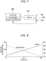
- Fig. 8 is a characteristic diagram of the DC motor 141.
- Fig. 9 is an operation flowchart of the control unit 160 according to the first embodiment.
- the control unit 160 is electrically connected to the DC motor 141.
- a rotation shaft of the DC motor 141 is mechanically connected to the speed reduction mechanism 143.
- An encoder 146 as a rotation detection unit that detects a rotation of the DC motor 141 is provided adjacent to the speed reduction mechanism 143.
- the encoder 146 includes a photointerrupter 144 including an optical sensor and a slit plate 145 in which a large number of slits are radially formed, and detects the rotation of the DC motor 141 by detecting whether or not light passes through the slits of the slit plate 145 with the optical sensor of the photointerrupter 144.
- the photointerrupter 144 is electrically connected to the control unit 160.
- the control unit 160 has a rotation speed calculation function of calculating the rotation speed of the DC motor 141 based on the rotation of the DC motor 141 detected by the encoder 146. Furthermore, the control unit 160 detects the abnormality in administration when the rotation speed of the DC motor 141 calculated by the rotation speed calculation function is lower than a predetermined lower limit rotation speed. Note that, in the present embodiment, the encoder 146 using the photointerrupter 144 as the rotation detection unit has been exemplified, but an encoder using a magnetic sensor may be used.
- the control unit 160 rotates the DC motor 141, the speed reduction mechanism 143 is driven, and the plunger 130 advances in the liquid medicine container 110 (see Figs. 5 and 6 ).
- the encoder 146 provided adjacent to the speed reduction mechanism 143 detects the rotation of the DC motor 141, and the control unit 160 calculates the rotation speed of the DC motor 141 based on the rotation of the DC motor 141 detected by the encoder 146.
- the rotation of the DC motor 141 detected by the encoder 146 is fed back to the control unit 160, and the control unit 160 rotates the DC motor 141 at a preset constant rotation speed in accordance with the feedback According to this, the liquid medicine filled in the liquid medicine container 110 is fed to the lumen of the needle tube 220 via the flow path of the tube 240 and the puncture unit 230, and the liquid medicine is administered to the living body at a constant speed (see Fig. 1 ).
- the current flowing in the DC motor 141 increases as the load increases (torque increases), and conversely, the rotation speed of the DC motor 141 decreases as the load increases.
- the control unit 160 starts the DC motor 141 when the liquid medicine is administered to the living body (S100), and determines whether or not the rotation speed of the DC motor 141 is lower than a predetermined rotation speed (S101).
- the rotation speed of the DC motor 141 when the liquid medicine is administered to the living body is set in advance in accordance with the administration speed of the liquid medicine.
- the rotation speed of the DC motor 141 is not lower than the predetermined rotation speed (when the rotation speed is not lower than a lower limit rotation speed) (S101: NO)
- it can be determined that the liquid medicine is normally administered, and thus the liquid medicine is continued to be administered as it is.
- the control unit 160 determines that the abnormality in administration occurs (S102).
- the control unit 160 stops the DC motor 141 (S103) and notifies a user of the abnormality in administration (S104).
- an LED may be provided in a casing of the liquid medicine administration device 100 and the LED may be turned on and blinked, or a speaker may be provided in the casing of the liquid medicine administration device 100 and the speaker may sound.
- the occurrence of the abnormality in administration may be wirelessly notified to an external computer.
- the liquid medicine administration device 100 originally includes the encoder 146 in order to control the rotation speed of the DC motor 141. Therefore, in order to cause the control unit 160 to implement the operation as in the present embodiment, it is only necessary to rewrite a program included in the control unit 160, and thus it is not necessary to change the mechanical configuration of the liquid medicine administration device 100 of the related art. Therefore, the present invention can be inexpensively applied to the liquid medicine administration device 100 of the related art.
- Fig. 10 is a block diagram of a control system of the liquid medicine administration device according to the second embodiment.
- Fig. 11 is an operation flowchart of the control unit according to the second embodiment.
- the control unit 160 is electrically connected to the power supply unit 170.
- the control unit 160 is electrically connected to the DC motor 141.
- the DC motor 141 is rotated by electric power supplied from the power supply unit 170.
- the rotation speed of the DC motor 141 is controlled by the control unit 160.
- the control unit 160 has a current value measurement function of measuring a value of a motor current flowing in the DC motor 141. Furthermore, the control unit 160 detects the abnormality in administration when the value of the motor current exceeds a predetermined upper limit current value.
- control unit 160 rotates the DC motor 141, the speed reduction mechanism 143 is driven, and the plunger 130 advances in the liquid medicine container 110 (see Figs. 5 and 6 ).
- the control unit 160 rotates the DC motor 141 at a preset constant rotation speed. According to this, the liquid medicine filled in the liquid medicine container 110 is fed to the lumen of the needle tube 220 via the flow path of the tube 240 and the puncture unit 230, and the liquid medicine is administered to the living body at a constant speed (see Fig. 1 ).
- the current flowing in the DC motor 141 increases as the load increases (torque increases), and conversely, the rotation speed of the DC motor 141 decreases as the load increases.
- control unit 160 starts the DC motor 141 when the liquid medicine is administered to the living body
- S200 determines whether or not the current flowing in the DC motor 141 is greater than a predetermined current value (S201).
- a predetermined current value when the current flowing in the DC motor 141 is not greater than the predetermined current value (when the current does not exceed an upper limit current value) (S201: NO), it can be determined that the liquid medicine is normally administered, and thus the liquid medicine is continued to be administered as it is.
- the control unit 160 determines that the abnormality in administration occurs (S202).
- control unit 160 stops the DC motor 141 (S203) and notifies a user of the abnormality in administration (S204).
- a form of the notification of the abnormality in administration is the same as that in the first embodiment.
- Fig. 12 is a block diagram of a control system of the liquid medicine administration device according to the third embodiment.
- Fig. 13 is a diagram illustrating an example of a current limiting circuit of Fig. 12 .
- Fig. 14 is an operation flowchart of the control unit according to the third embodiment.
- the control unit 160 is electrically connected to the power supply unit 170.
- the control unit 160 is electrically connected to the DC motor 141.
- the DC motor 141 is connected to a current limiting circuit 148.
- the DC motor 141 is rotated by electric power supplied from the power supply unit 170.
- the rotation speed of the DC motor 141 is controlled by the control unit 160.
- the current limiting circuit 148 limits the current so that any current equal to or greater than a predetermined current does not flow in the DC motor 141.
- the current limiting circuit 148 can be realized as a circuit as illustrated in Fig. 13 as an example. Since the circuit of Fig. 13 is a general known circuit, it will not be described in detail.
- the current flowing in the DC motor 141 increases as the load increases (torque increases), and conversely, the rotation speed of the DC motor 141 decreases as the load increases. Therefore, when the DC motor 141 rotates at a preset constant rotation speed, the current flowing in the DC motor 141 is not limited to the current limiting circuit 148.
- the current flowing in the DC motor 141 increases in accordance with the magnitude of the load. Therefore, the current flowing in the DC motor 141 is limited by the current limiting circuit 148. In a case where the current is limited when the load increases, the DC motor 141 stops due to insufficient torque.
- the control unit 160 rotates the DC motor 141, the speed reduction mechanism 143 is driven, and the plunger 130 advances in the liquid medicine container 110 (see Figs. 5 and 6 ).
- the control unit 160 rotates the DC motor 141 at a preset constant rotation speed.
- the current flowing in the DC motor 141 is not limited by the current limiting circuit 148. Therefore, the liquid medicine filled in the liquid medicine container 110 is fed to the lumen of the needle tube 220 via the tube 240 and the flow path of the puncture unit 230, and the liquid medicine is administered to the living body at a constant speed (see Fig. 1 ).
- the stop of the rotation of the DC motor 141 is detected as follows.
- the control unit 160 starts the DC motor 141 when the liquid medicine is administered to the living body (S300).
- the control unit 160 determines whether or not completion of feeding of the liquid medicine has been detected within a predetermined time (S301). Normally, until a predetermined time elapses after the DC motor 141 is started, the plunger 130 pushes the liquid medicine in the liquid medicine container 110, and the portion 134 to be detected included in the plunger 130 comes into contact with the detection unit 150. However, when the supply path is blocked for some reason, the current limiting circuit 148 acts to extremely slow or stop the rotation of the DC motor 141.
- Step S301 it is determined whether or not the portion 134 to be detected included in the plunger 130 comes into contact with the detection unit 150 within a predetermined time after the control unit 160 starts the DC motor 141.
- the processing is ended.
- the load on the DC motor 141 increases and it is considered that an abnormality such as blockage of the supply path of the liquid medicine occurs (S301: NO).
- control unit 160 determines that the abnormality in administration occurs (S302). Next, the control unit 160 stops the DC motor 141 by blocking the current supplied to the DC motor 141 (S303), and notifies a user of the abnormality in administration (S304). A form of the notification of the abnormality in administration is the same as that in the first embodiment.
- liquid medicine administration device of the present invention has been described above through a plurality of the embodiments, but the present invention is not limited to each of the configurations described above, and can be appropriately changed based on the description of the claims.
Landscapes
- Health & Medical Sciences (AREA)
- Heart & Thoracic Surgery (AREA)
- Vascular Medicine (AREA)
- Engineering & Computer Science (AREA)
- Anesthesiology (AREA)
- Biomedical Technology (AREA)
- Hematology (AREA)
- Life Sciences & Earth Sciences (AREA)
- Animal Behavior & Ethology (AREA)
- General Health & Medical Sciences (AREA)
- Public Health (AREA)
- Veterinary Medicine (AREA)
- Dermatology (AREA)
- Infusion, Injection, And Reservoir Apparatuses (AREA)
Abstract
Description
- The present invention relates to a liquid medicine administration device capable of detecting an abnormality in administration of a liquid medicine.
- In the related art, as disclosed in Patent Literature 1, there is known a syringe pump type liquid medicine administration device that administers a liquid medicine filled in a liquid medicine container to a living body. The syringe pump type liquid medicine administration device includes a drive mechanism and a control unit, and continuously administers a liquid medicine with high accuracy for a long time by moving a plunger little by little by the drive mechanism.
- Patent Literature 1:
JP 2015-181869 A - At the time of using the liquid medicine administration device, when a power switch is turned on, the control unit drives the drive mechanism, and moves the plunger little by little to administer the liquid medicine to the living body. However, in a case where a supply path for administering the liquid medicine to the living body is blocked for some reason, the liquid medicine leaks from the middle of the supply path since pressure of the plunger cannot be withstood, and the liquid medicine administration device itself is damaged since the drive mechanism or the motor is overloaded. In a case where the liquid medicine has leaked out, the load on the motor decreases, and thus the abnormality in administration cannot be detected even when it is detected whether or not the motor is rotating.
- An object of the present invention is to provide a liquid medicine administration device capable of detecting an abnormality in administration of a liquid medicine.
- In order to achieve the object described above, an aspect of the present invention provides a liquid medicine administration device including: a plunger that pushes a liquid medicine in a liquid medicine container filled with the liquid medicine; a supply path that causes a distal end opening of the liquid medicine container to communicate with a needle in order to administer the liquid medicine from the needle pierced into a living body; a drive mechanism that advances the plunger toward the distal end opening of the liquid medicine container in order to discharge the liquid medicine from the liquid medicine container; and a control unit that controls operation of the drive mechanism, in which the drive mechanism includes a DC motor that applies, to the plunger, a drive force for advancing the plunger, and a rotation detection unit that detects a rotation of the DC motor, and the control unit has a rotation speed calculation function of calculating a rotation speed of the DC motor based on the rotation of the DC motor detected by the rotation detection unit, and detects an abnormality in administration when the rotation speed of the DC motor calculated by the rotation speed calculation function is lower than a predetermined lower limit rotation speed.
- In order to achieve the object described above, another aspect of the present invention provides a liquid medicine administration device including: a plunger that pushes a liquid medicine in a liquid medicine container filled with the liquid medicine; a supply path that causes a distal end opening of the liquid medicine container to communicate with a needle in order to administer the liquid medicine from the needle pierced into a living body; a drive mechanism that advances the plunger toward the distal end opening of the liquid medicine container in order to discharge the liquid medicine from the liquid medicine container; and a control unit that controls operation of the drive mechanism, in which the drive mechanism includes a DC motor that applies, to the plunger, a drive force for advancing the plunger, and the control unit has a current value measurement function of measuring a value of a motor current flowing in the DC motor, and detects an abnormality in administration when the value of the motor current exceeds a predetermined upper limit current value.
- In order to achieve the object described above, still another aspect of the present invention provides a liquid medicine administration device including: a plunger that pushes a liquid medicine in a liquid medicine container filled with the liquid medicine; a supply path that causes a distal end opening of the liquid medicine container to communicate with a needle in order to administer the liquid medicine from the needle pierced into a living body; a drive mechanism that advances the plunger toward the distal end opening of the liquid medicine container in order to discharge the liquid medicine from the liquid medicine container and includes a DC motor that applies, to the plunger, a drive force for advancing the plunger; a control unit that controls operation of the drive mechanism; and a current limiting circuit that limits a current so that any current equal to or greater than a predetermined current does not flow in the DC motor.
- According to the aspects of the present invention, in the liquid medicine administration device, since the abnormality in administration of the liquid medicine can be detected, it is possible to prevent the liquid medicine from leaking out or the liquid medicine administration device from being damaged.
-
-
Fig. 1 is a side view of a liquid medicine administration system. -
Fig. 2 is a view schematically illustrating a usage example of a liquid medicine administration system. -
Fig. 3 is a schematic perspective view of a liquid medicine administration device. -
Fig. 4 is a schematic perspective view of a chassis included in a housing and each component member assembled to the chassis. -
Fig. 5 is a plan view of a liquid medicine administration device illustrating a state before a plunger is moved forward. -
Fig. 6 is a plan view of a liquid medicine administration device illustrating a state after the plunger is moved forward. -
Fig. 7 is a block diagram of a control system of a liquid medicine administration device according to a first embodiment. -
Fig. 8 is a characteristic diagram of a DC motor. -
Fig. 9 is an operation flowchart of a control unit according to the first embodiment. -
Fig. 10 is a block diagram of a control system of a liquid medicine administration device according to a second embodiment. -
Fig. 11 is an operation flowchart of a control unit according to the second embodiment. -
Fig. 12 is a block diagram of a control system of a liquid medicine administration device according to a third embodiment. -
Fig. 13 is a diagram illustrating an example of a current limiting circuit ofFig. 12 . -
Fig. 14 is an operation flowchart of a control unit according to a third embodiment. - Hereinafter, embodiments of the present invention will be described with reference to the accompanying drawings. Note that, the following description does not limit the technical scope or meaning of terms described in the claims. Furthermore, dimensional ratios in the drawings are exaggerated for convenience of description, and may be different from actual ratios.
-
Figs. 1 to 6 are views for explaining a liquidmedicine administration system 10, a liquidmedicine administration device 100, and anadministration tool 200 according to the present embodiment.Fig. 1 is a side view of a liquid medicine administration system.Fig. 2 is a view schematically illustrating a usage example of the liquid medicine administration system.Fig. 3 is a schematic perspective view of a liquid medicine administration device.Fig. 4 is a schematic perspective view of a chassis included in a housing and each component member assembled to the chassis.Fig. 5 is a plan view of the liquid medicine administration device illustrating a state before a plunger is moved forward.Fig. 6 is a plan view of the liquid medicine administration device illustrating a state after the plunger is moved forward. Note that, an arrow X in each drawing indicates a "longitudinal direction (longitudinal direction of a liquid medicine container 110)" of the liquidmedicine administration device 100, an arrow Y indicates a "width direction (depth direction)" of the liquidmedicine administration device 100, and an arrow Z indicates a "height direction" of the liquidmedicine administration device 100. - The liquid
medicine administration system 10 is used to administer a liquid medicine into a living body. As illustrated inFig. 1 , the liquidmedicine administration system 10 includes the liquidmedicine administration device 100 and theadministration tool 200. - As illustrated in
Fig. 2 , the liquidmedicine administration device 100 and theadministration tool 200 are configured as a patch type used by being stuck on a body surface (skin) H of a user. A body part of the user to which the liquidmedicine administration device 100 and theadministration tool 200 are attached is not particularly limited, but is, for example, an abdomen or a femoral part. - For example, the liquid
medicine administration system 10 can continuously administer a liquid medicine (not illustrated) filled in theliquid medicine container 110 included in the liquidmedicine administration device 100 into the living body for a relatively long time (for example, approximately several minutes to several hours) by a pressing action of a plunger 130 (seeFig. 4 ) to be described later. Note that, the liquidmedicine administration system 10 may intermittently administer the liquid medicine into the living body. - As illustrated in
Figs. 3 to 6 , the liquidmedicine administration device 100 includes theliquid medicine container 110 including a cylindrical (barrel-shaped)main body 111 filled with the liquid medicine, ahousing 120 that holds theliquid medicine container 110, theplunger 130 that pushes the liquid medicine in theliquid medicine container 110, adrive mechanism 140 that advances theplunger 130 toward a distal end opening of theliquid medicine container 110, adetection unit 150 that detects aportion 134 to be detected of theplunger 130 and detects completion of feeding of the liquid medicine based on a detection result, and acontrol unit 160 that controls operation of thedrive mechanism 140. - As illustrated in
Figs. 3 and 4 , thehousing 120 includes a box-shaped housingmain body 120a in which anaccommodation space 128 is formed, and a chassis (corresponding to a "support portion") 127 which is accommodated in theaccommodation space 128 of the housingmain body 120a and can be fixed to the housingmain body 120a. - As illustrated in
Fig. 3 , awindow portion 123a that allows the inside of theaccommodation space 128 to be visually recognized from the outside of thehousing 120 is formed on anupper surface 123 of the housingmain body 120a. Thewindow portion 123a is formed by providing a transparent or translucent portion in a part of the housingmain body 120a. - A
proximal end opening 125 for inserting achassis 127 into theaccommodation space 128 of the housingmain body 120a is formed on a proximal end side in a longitudinal direction of the housingmain body 120a. The proximal end opening 125 of the housingmain body 120a is closed by a lid member (not illustrated) in a state in which thechassis 127 is accommodated in theaccommodation space 128. - A
bottom surface 121 of the housingmain body 120a is provided with a sheet-like sticking portion (not illustrated) that can be stuck to the body surface H of the user. In an initial state before the liquidmedicine administration device 100 is attached to the user, a peelable protective sheet is attached to a sticking surface of the sticking portion. - As illustrated in
Fig. 4 , thechassis 127 holds theliquid medicine container 110, theplunger 130, thedrive mechanism 140, thedetection unit 150, thecontrol unit 160, and apower supply unit 170. - The
liquid medicine container 110 is a so-called prefilled liquid medicine container. Therefore, the liquid medicine is filled in alumen 111a of themain body 111 of theliquid medicine container 110 in advance. Examples of the liquid medicine include protein preparations, narcotic analgesics, diuretics, and the like. - A sealing member (not illustrated) for preventing leakage of the liquid medicine is disposed in the distal end opening (discharge port) formed at a
distal end 112 of theliquid medicine container 110. As illustrated inFig. 3 , the distal end opening of theliquid medicine container 110 is disposed so as to protrude outward from the housingmain body 120a. Furthermore, anattachment portion 115 that is connected to a tube 240 (seeFig. 1 ) to be described later is attached to a distal end portion of theliquid medicine container 110, the distal end portion protruding from the housingmain body 120a. - A
main body 131 of theplunger 130 is inserted into thelumen 111a of themain body 111 of the liquid medicine container 110 (seeFigs. 4 and5 ). Agasket 135 slidable on an inner wall of theliquid medicine container 110 is disposed at a distal end of themain body 131 of theplunger 130. Thegasket 135 liquid-tightly seals a proximal end side of thegasket 135 by liquid-tightly bringing an outer circumferential portion of thegasket 135 into close contact with an inner circumferential surface of themain body 111 of theliquid medicine container 110. - In the present embodiment, the
gasket 135 is configured to be shrinkable in a direction (longitudinal direction) in which theplunger 130 advances when theplunger 130 advances in a state in which thegasket 135 abuts against a distal endinner wall 112a (seeFig. 5 ) of theliquid medicine container 110. Thegasket 135 can be made of, for example, a flexible resin material such as a rubber material or an elastomer so as to be shrinkable as described above. - As illustrated in
Fig. 5 , thegasket 135 has a tapered shape in which an outer diameter decreases toward a distal end side. Furthermore, the shape of thegasket 135 is substantially the same as the shape of the distal endinner wall 112a of theliquid medicine container 110. - As illustrated in
Fig. 5 , theportion 134 to be detected is provided at a proximal end of theplunger 130. Theportion 134 to be detected is used to detect completion of feeding of the liquid medicine by the liquidmedicine administration device 100. - The
control unit 160 controls a liquid medicine feeding operation of the liquidmedicine administration device 100. Thecontrol unit 160 can be configured by, for example, a known microcomputer (electronic circuit element) on which a CPU, a RAM, a ROM, and the like are mounted. Thecontrol unit 160 integrally controls operations of thedrive mechanism 140, thedetection unit 150, and thepower supply unit 170. - As illustrated in
Fig. 5 , thedetection unit 150 is disposed in thechassis 127. As illustrated inFig. 6 , thedetection unit 150 detects completion of feeding of the liquid medicine of the liquidmedicine administration device 100 when theportion 134 to be detected included in theplunger 130 comes into contact with thedetection unit 150. Thedetection unit 150 can be configured by, for example, a known contact-type sensor that transmits a predetermined electric signal when theportion 134 to be detected comes into contact with thedetection unit 150. Thecontrol unit 160 acquires information regarding completion of feeding of the liquid medicine by receiving the electric signal from theportion 134 to be detected. Note that, when theplunger 130 advances by a predetermined amount, the specific configuration and the like of thedetection unit 150 are not particularly limited as long as a position of theportion 134 to be detected of theplunger 130 can be detected. - The
power supply unit 170 can be configured by, for example, a known button battery or the like. The liquidmedicine administration device 100 is required to be downsized. Therefore, a small button battery is used as thepower supply unit 170. - As illustrated in
Fig. 4 , thedrive mechanism 140 includes aDC motor 141 that receives a drive current from thepower supply unit 170 and applies a drive force, aspeed reduction mechanism 143 that includes a gear or the like transmitting the drive force of theDC motor 141, an encoder (seeFig. 7 ) that is provided adjacent to thespeed reduction mechanism 143 and includes a photointerrupter as a rotation detection unit that detects a rotation of theDC motor 141 and a slit plate that rotates in accordance with the rotation of theDC motor 141, and afeed screw 147 that is connected to thespeed reduction mechanism 143. - The
feed screw 147 is connected to a proximalend connection portion 133 disposed in the vicinity of the proximal end of theplunger 130. Thefeed screw 147 converts a rotational motion transmitted from thespeed reduction mechanism 143 into a linear motion to advance theplunger 130 in the longitudinal direction (X direction). Theplunger 130 advances toward a distal end side of theliquid medicine container 110 to push the liquid medicine from thelumen 111a of themain body 111 of theliquid medicine container 110 to the tube 240 (seeFig. 1 ). - As illustrated in
Figs. 1 and 2 , theadministration tool 200 is configured to be connectable to the liquidmedicine administration device 100. - The
administration tool 200 includes aconnector 210, aneedle tube 220 that punctures the living body, a puncture unit (cannula housing) 230, thetube 240, and apuncture assisting tool 250 that assists in puncturing the living body with theneedle tube 220. - The
connector 210 is configured to be connectable to the liquidmedicine administration device 100 via anattachment portion 215 fixed to theconnector 210. Theattachment portion 215 can be connected to the liquidmedicine administration device 100 by being externally fitted to the attachment portion 115 (seeFig. 4 ) provided in the vicinity of thedistal end 112 of theliquid medicine container 110 protruding to the outside of thehousing 120. - Inside the
attachment portion 215, a connection needle portion (not illustrated) through which the sealing member (not illustrated) disposed at a distal end portion of theliquid medicine container 110 can be inserted is disposed. Thetube 240 communicates with thelumen 111a of themain body 111 of theliquid medicine container 110 via the connection needle portion. - Inside the
puncture unit 230, a flow path (not illustrated) through which thetube 240 communicates with a lumen of theneedle tube 220 is formed. The liquid medicine fed to thepuncture unit 230 through thetube 240 is administered into the living body through the flow path formed inside thepuncture unit 230 and theneedle tube 220. - When the liquid medicine is fed to the user, the
puncture assisting tool 250 is attached to thepuncture unit 230. Thepuncture assisting tool 250 holds an introduction needle (inner needle) 251. Theintroduction needle 251 protrudes from a distal end of theneedle tube 220 in a state in which thepuncture assisting tool 250 is attached to thepuncture unit 230. By puncturing the living body with theneedle tube 220 in a state in which theintroduction needle 251 is inserted into theneedle tube 220, the user can insert theneedle tube 220 into the living body while preventing theneedle tube 220 from being broken or the like. - The
puncture assisting tool 250 is removed from thepuncture unit 230 after puncturing the living body with theneedle tube 220. When thepuncture assisting tool 250 is removed from thepuncture unit 230, theintroduction needle 251 is removed from the lumen of theneedle tube 220. - After puncturing the living body with the
needle tube 220, thepuncture assisting tool 250 is removed, and thepuncture unit 230 is left on the body surface H of the user in a state in which theneedle tube 220 is indwelled in the living body. When theplunger 130 of the liquidmedicine administration device 100 advances in theliquid medicine container 110 in this state, the liquid medicine filled in theliquid medicine container 110 is fed to the lumen of theneedle tube 220 via thetube 240 and the flow path of thepuncture unit 230. - The
introduction needle 251 can be formed of, for example, a metal needle. Furthermore, theneedle tube 220 can be formed of, for example, a resin tubular member (cannula). - Similarly to the liquid
medicine administration device 100, theadministration tool 200 is configured as a patch type used by being stuck on the body surface H of the user. A sheet-like sticking portion (not illustrated) that can be stuck to the body surface H is provided on a contact surface (bottom surface) 231 of thepuncture unit 230 of theadministration tool 200. In an initial state before theadministration tool 200 is attached to the user, a peelable protective sheet is attached to a sticking surface of the sticking portion. - As described above, a schematic configuration of the liquid
medicine administration system 10, the liquidmedicine administration device 100, and theadministration tool 200 has been described. The liquidmedicine administration device 100 is required to be reduced in size and cost in order to facilitate handling at the time of use and to save a storage space at the time of storage. Therefore, as theDC motor 141, a coreless DC motor, which is easily downsized and has high torque efficiency with respect to electric power, is used. The DC motor has a characteristic that a current supplied to the DC motor and a rotation speed of the DC motor are different depending on the magnitude of a load torque. Thecontrol unit 160 detects the abnormality in administration by using the characteristic of theDC motor 141. Therefore, thecontrol unit 160 controls thedrive mechanism 140 as follows. Control of thedrive mechanism 140 by thecontrol unit 160 will be described separately in the first embodiment to the third embodiment. - A specific operation of the
control unit 160 according to the first embodiment will be described with reference toFigs. 7 to 9 .Fig. 7 is a block diagram of a control system of the liquidmedicine administration device 100 according to the first embodiment.Fig. 8 is a characteristic diagram of theDC motor 141.Fig. 9 is an operation flowchart of thecontrol unit 160 according to the first embodiment. - The
control unit 160 is electrically connected to theDC motor 141. A rotation shaft of theDC motor 141 is mechanically connected to thespeed reduction mechanism 143. Anencoder 146 as a rotation detection unit that detects a rotation of theDC motor 141 is provided adjacent to thespeed reduction mechanism 143. Theencoder 146 includes aphotointerrupter 144 including an optical sensor and aslit plate 145 in which a large number of slits are radially formed, and detects the rotation of theDC motor 141 by detecting whether or not light passes through the slits of theslit plate 145 with the optical sensor of thephotointerrupter 144. Thephotointerrupter 144 is electrically connected to thecontrol unit 160. Thecontrol unit 160 has a rotation speed calculation function of calculating the rotation speed of theDC motor 141 based on the rotation of theDC motor 141 detected by theencoder 146. Furthermore, thecontrol unit 160 detects the abnormality in administration when the rotation speed of theDC motor 141 calculated by the rotation speed calculation function is lower than a predetermined lower limit rotation speed. Note that, in the present embodiment, theencoder 146 using thephotointerrupter 144 as the rotation detection unit has been exemplified, but an encoder using a magnetic sensor may be used. - When the
control unit 160 rotates theDC motor 141, thespeed reduction mechanism 143 is driven, and theplunger 130 advances in the liquid medicine container 110 (seeFigs. 5 and 6 ). Theencoder 146 provided adjacent to thespeed reduction mechanism 143 detects the rotation of theDC motor 141, and thecontrol unit 160 calculates the rotation speed of theDC motor 141 based on the rotation of theDC motor 141 detected by theencoder 146. The rotation of theDC motor 141 detected by theencoder 146 is fed back to thecontrol unit 160, and thecontrol unit 160 rotates theDC motor 141 at a preset constant rotation speed in accordance with the feedback According to this, the liquid medicine filled in theliquid medicine container 110 is fed to the lumen of theneedle tube 220 via the flow path of thetube 240 and thepuncture unit 230, and the liquid medicine is administered to the living body at a constant speed (seeFig. 1 ). - In characteristics of the
DC motor 141 used in the present embodiment, as illustrated inFig. 8 , the current flowing in theDC motor 141 increases as the load increases (torque increases), and conversely, the rotation speed of theDC motor 141 decreases as the load increases. - Therefore, as illustrated in the operation flowchart of
Fig. 9 , thecontrol unit 160 starts theDC motor 141 when the liquid medicine is administered to the living body (S100), and determines whether or not the rotation speed of theDC motor 141 is lower than a predetermined rotation speed (S101). The rotation speed of theDC motor 141 when the liquid medicine is administered to the living body is set in advance in accordance with the administration speed of the liquid medicine. When the rotation speed of theDC motor 141 is not lower than the predetermined rotation speed (when the rotation speed is not lower than a lower limit rotation speed) (S101: NO), it can be determined that the liquid medicine is normally administered, and thus the liquid medicine is continued to be administered as it is. On the other hand, when the rotation speed of theDC motor 141 is lower than the predetermined rotation speed (when the rotation speed is lower than the lower limit rotation speed), the load on theDC motor 141 increases and it is considered that an abnormality such as blockage of the supply path of the liquid medicine occurs (S101: YES). Therefore, thecontrol unit 160 determines that the abnormality in administration occurs (S102). Next, thecontrol unit 160 stops the DC motor 141 (S103) and notifies a user of the abnormality in administration (S104). In notification of the abnormality in administration, for example, an LED may be provided in a casing of the liquidmedicine administration device 100 and the LED may be turned on and blinked, or a speaker may be provided in the casing of the liquidmedicine administration device 100 and the speaker may sound. Furthermore, the occurrence of the abnormality in administration may be wirelessly notified to an external computer. - The liquid
medicine administration device 100 originally includes theencoder 146 in order to control the rotation speed of theDC motor 141. Therefore, in order to cause thecontrol unit 160 to implement the operation as in the present embodiment, it is only necessary to rewrite a program included in thecontrol unit 160, and thus it is not necessary to change the mechanical configuration of the liquidmedicine administration device 100 of the related art. Therefore, the present invention can be inexpensively applied to the liquidmedicine administration device 100 of the related art. - Next, a specific operation of the
control unit 160 according to a second embodiment will be described with reference toFigs. 10 and11 .Fig. 10 is a block diagram of a control system of the liquid medicine administration device according to the second embodiment.Fig. 11 is an operation flowchart of the control unit according to the second embodiment. - The
control unit 160 is electrically connected to thepower supply unit 170. Thecontrol unit 160 is electrically connected to theDC motor 141. TheDC motor 141 is rotated by electric power supplied from thepower supply unit 170. The rotation speed of theDC motor 141 is controlled by thecontrol unit 160. Thecontrol unit 160 has a current value measurement function of measuring a value of a motor current flowing in theDC motor 141. Furthermore, thecontrol unit 160 detects the abnormality in administration when the value of the motor current exceeds a predetermined upper limit current value. - When the
control unit 160 rotates theDC motor 141, thespeed reduction mechanism 143 is driven, and theplunger 130 advances in the liquid medicine container 110 (seeFigs. 5 and 6 ). Thecontrol unit 160 rotates theDC motor 141 at a preset constant rotation speed. According to this, the liquid medicine filled in theliquid medicine container 110 is fed to the lumen of theneedle tube 220 via the flow path of thetube 240 and thepuncture unit 230, and the liquid medicine is administered to the living body at a constant speed (seeFig. 1 ). - In characteristics of the
DC motor 141 used in the present embodiment, as illustrated inFig. 8 , the current flowing in theDC motor 141 increases as the load increases (torque increases), and conversely, the rotation speed of theDC motor 141 decreases as the load increases. - Therefore, as illustrated in the operation flowchart of
Fig. 11 , thecontrol unit 160 starts theDC motor 141 when the liquid medicine is administered to the living body - (S200), and determines whether or not the current flowing in the
DC motor 141 is greater than a predetermined current value (S201). When the current flowing in theDC motor 141 is not greater than the predetermined current value (when the current does not exceed an upper limit current value) (S201: NO), it can be determined that the liquid medicine is normally administered, and thus the liquid medicine is continued to be administered as it is. On the other hand, when the current flowing in theDC motor 141 is greater than the predetermined current value (current exceeds the upper limit current value), the load on theDC motor 141 increases and it is considered that an abnormality such as blockage of the supply path of the liquid medicine occurs (S201: YES). Therefore, thecontrol unit 160 determines that the abnormality in administration occurs (S202). - Next, the
control unit 160 stops the DC motor 141 (S203) and notifies a user of the abnormality in administration (S204). A form of the notification of the abnormality in administration is the same as that in the first embodiment. - Next, a specific operation of the
control unit 160 according to a third embodiment will be described with reference toFigs. 12 to 14 .Fig. 12 is a block diagram of a control system of the liquid medicine administration device according to the third embodiment.Fig. 13 is a diagram illustrating an example of a current limiting circuit ofFig. 12 .Fig. 14 is an operation flowchart of the control unit according to the third embodiment. - The
control unit 160 is electrically connected to thepower supply unit 170. Thecontrol unit 160 is electrically connected to theDC motor 141. TheDC motor 141 is connected to a current limitingcircuit 148. TheDC motor 141 is rotated by electric power supplied from thepower supply unit 170. The rotation speed of theDC motor 141 is controlled by thecontrol unit 160. The current limitingcircuit 148 limits the current so that any current equal to or greater than a predetermined current does not flow in theDC motor 141. The current limitingcircuit 148 can be realized as a circuit as illustrated inFig. 13 as an example. Since the circuit ofFig. 13 is a general known circuit, it will not be described in detail. - In characteristics of the
DC motor 141 used in the present embodiment, as illustrated inFig. 8 , the current flowing in theDC motor 141 increases as the load increases (torque increases), and conversely, the rotation speed of theDC motor 141 decreases as the load increases. Therefore, when theDC motor 141 rotates at a preset constant rotation speed, the current flowing in theDC motor 141 is not limited to the current limitingcircuit 148. On the other hand, when a load is applied to theDC motor 141 and the rotation speed is lower than a preset constant rotation speed, the current flowing in theDC motor 141 increases in accordance with the magnitude of the load. Therefore, the current flowing in theDC motor 141 is limited by the current limitingcircuit 148. In a case where the current is limited when the load increases, theDC motor 141 stops due to insufficient torque. - When the
control unit 160 rotates theDC motor 141, thespeed reduction mechanism 143 is driven, and theplunger 130 advances in the liquid medicine container 110 (seeFigs. 5 and 6 ). Thecontrol unit 160 rotates theDC motor 141 at a preset constant rotation speed. When theDC motor 141 rotates at a constant speed, the current flowing in theDC motor 141 is not limited by the current limitingcircuit 148. Therefore, the liquid medicine filled in theliquid medicine container 110 is fed to the lumen of theneedle tube 220 via thetube 240 and the flow path of thepuncture unit 230, and the liquid medicine is administered to the living body at a constant speed (seeFig. 1 ). On the other hand, in a case where the supply path for administering the liquid medicine to the living body is blocked for some reason, the load on theDC motor 141 increases, the current flowing in theDC motor 141 increases, and the current flowing in theDC motor 141 is limited by the current limitingcircuit 148. Therefore, since the load on theDC motor 141 becomes too large, the rotation of theDC motor 141 is stopped. In the present embodiment, the stop of the rotation of theDC motor 141 is detected as follows. - As a first method of detecting that the rotation of the
DC motor 141 has stopped, as in the flowchart ofFig. 9 of the first embodiment, there is a method of determining that there is the abnormality in administration when the rotation speed of theDC motor 141 is lower than a predetermined rotation speed (when the rotation speed is lower than the lower limit rotation speed). This method is as described in the first embodiment. - As a second method of detecting that the rotation of the
DC motor 141 has stopped, as in the operation flowchart illustrated inFig. 14 , there is a method of determining that there is the abnormality in administration when the detection unit 150 (seeFig. 5 and Fig. 6 ) does not detect completion of feeding of the liquid medicine of the liquidmedicine administration device 100 after a predetermined time has elapsed. - As illustrated in the operation flowchart of
Fig. 14 , thecontrol unit 160 starts theDC motor 141 when the liquid medicine is administered to the living body (S300). Next, thecontrol unit 160 determines whether or not completion of feeding of the liquid medicine has been detected within a predetermined time (S301). Normally, until a predetermined time elapses after theDC motor 141 is started, theplunger 130 pushes the liquid medicine in theliquid medicine container 110, and theportion 134 to be detected included in theplunger 130 comes into contact with thedetection unit 150. However, when the supply path is blocked for some reason, the current limitingcircuit 148 acts to extremely slow or stop the rotation of theDC motor 141. Therefore, theportion 134 to be detected included in theplunger 130 does not come into contact with thedetection unit 150 until a predetermined time elapses. Therefore, in Step S301, it is determined whether or not theportion 134 to be detected included in theplunger 130 comes into contact with thedetection unit 150 within a predetermined time after thecontrol unit 160 starts theDC motor 141. When completion of feeding of the liquid medicine is detected within the predetermined time (S301: YES), since the feeding of the liquid medicine has been normally performed, the processing is ended. On the other hand, when the completion of feeding of the liquid medicine is not detected within the predetermined time, the load on theDC motor 141 increases and it is considered that an abnormality such as blockage of the supply path of the liquid medicine occurs (S301: NO). Therefore, thecontrol unit 160 determines that the abnormality in administration occurs (S302). Next, thecontrol unit 160 stops theDC motor 141 by blocking the current supplied to the DC motor 141 (S303), and notifies a user of the abnormality in administration (S304). A form of the notification of the abnormality in administration is the same as that in the first embodiment. - The liquid medicine administration device of the present invention has been described above through a plurality of the embodiments, but the present invention is not limited to each of the configurations described above, and can be appropriately changed based on the description of the claims.
-
- 10
- Liquid medicine administration system
- 100
- Liquid medicine administration device
- 110
- Liquid medicine container
- 111
- Main body of liquid medicine container
- 111a
- Lumen of liquid medicine container
- 112a
- Distal end inner wall of liquid medicine container
- 120
- Housing
- 120a
- Housing main body
- 127
- Chassis
- 128
- Accommodation space
- 130
- Plunger
- 131
- Main body of plunger
- 134
- Portion to be detected
- 135
- Gasket
- 135a
- Distal end of plunger
- 140
- Drive mechanism
- 141
- DC motor
- 143
- Speed reduction mechanism
- 144
- Photointerrupter
- 145
- Slit plate
- 146
- Encoder
- 148
- Current limiting circuit
- 150
- Detection unit
- 160
- Control unit
- H
- Body surface
Claims (6)
- A liquid medicine administration device comprising:a plunger that pushes a liquid medicine in a liquid medicine container filled with the liquid medicine;a supply path that causes a distal end opening of the liquid medicine container to communicate with a needle in order to administer the liquid medicine from the needle pierced into a living body;a drive mechanism that advances the plunger toward the distal end opening of the liquid medicine container in order to discharge the liquid medicine from the liquid medicine container; anda control unit that controls operation of the drive mechanism, whereinthe drive mechanism includes a DC motor that applies, to the plunger, a drive force for advancing the plunger, and a rotation detection unit that detects a rotation of the DC motor, andthe control unit has a rotation speed calculation function of calculating a rotation speed of the DC motor based on the rotation of the DC motor detected by the rotation detection unit, and detects an abnormality in administration when the rotation speed of the DC motor calculated by the rotation speed calculation function is lower than a predetermined lower limit rotation speed.
- The liquid medicine administration device according to claim 1, wherein the rotation detection unit is an encoder including a photointerrupter and a slit plate, the slit plate rotating in accordance with the rotation of the DC motor.
- The liquid medicine administration device according to claim 1 or 2, wherein the control unit stops the DC motor when detecting the abnormality in administration.
- The liquid medicine administration device according to claim 1 or 2, wherein when the abnormality in administration is detected, the control unit notifies that the abnormality in administration occurs.
- A liquid medicine administration device comprising:a plunger that pushes a liquid medicine in a liquid medicine container filled with the liquid medicine;a supply path that causes a distal end opening of the liquid medicine container to communicate with a needle in order to administer the liquid medicine from the needle pierced into a living body;a drive mechanism that advances the plunger toward the distal end opening of the liquid medicine container in order to discharge the liquid medicine from the liquid medicine container; anda control unit that controls operation of the drive mechanism, whereinthe drive mechanism includes a DC motor that applies, to the plunger, a drive force for advancing the plunger, andthe control unit has a current value measurement function of measuring a value of a motor current flowing in the DC motor, and detects an abnormality in administration when the value of the motor current exceeds a predetermined upper limit current value.
- A liquid medicine administration device comprising:a plunger that pushes a liquid medicine in a liquid medicine container filled with the liquid medicine;a supply path that causes a distal end opening of the liquid medicine container to communicate with a needle in order to administer the liquid medicine from the needle pierced into a living body;a drive mechanism that advances the plunger toward the distal end opening of the liquid medicine container in order to discharge the liquid medicine from the liquid medicine container and includes a DC motor that applies, to the plunger, a drive force for advancing the plunger;a control unit that controls operation of the drive mechanism; anda current limiting circuit that limits a current so that any current equal to or greater than a predetermined current does not flow in the DC motor.
Applications Claiming Priority (2)
| Application Number | Priority Date | Filing Date | Title |
|---|---|---|---|
| JP2019066300 | 2019-03-29 | ||
| PCT/JP2020/009151 WO2020203004A1 (en) | 2019-03-29 | 2020-03-04 | Liquid medicine administration apparatus |
Publications (2)
| Publication Number | Publication Date |
|---|---|
| EP3932450A1 true EP3932450A1 (en) | 2022-01-05 |
| EP3932450A4 EP3932450A4 (en) | 2022-04-27 |
Family
ID=72668654
Family Applications (1)
| Application Number | Title | Priority Date | Filing Date |
|---|---|---|---|
| EP20784086.9A Withdrawn EP3932450A4 (en) | 2019-03-29 | 2020-03-04 | Liquid medicine administration apparatus |
Country Status (5)
| Country | Link |
|---|---|
| US (1) | US20220008646A1 (en) |
| EP (1) | EP3932450A4 (en) |
| JP (1) | JPWO2020203004A1 (en) |
| CN (1) | CN113573754A (en) |
| WO (1) | WO2020203004A1 (en) |
Families Citing this family (1)
| Publication number | Priority date | Publication date | Assignee | Title |
|---|---|---|---|---|
| WO2026009608A1 (en) * | 2024-07-02 | 2026-01-08 | ニプロ株式会社 | Pump, system, and method |
Family Cites Families (6)
| Publication number | Priority date | Publication date | Assignee | Title |
|---|---|---|---|---|
| US7766873B2 (en) * | 1998-10-29 | 2010-08-03 | Medtronic Minimed, Inc. | Method and apparatus for detecting occlusions in an ambulatory infusion pump |
| GB0020058D0 (en) * | 2000-08-16 | 2000-10-04 | Smiths Industries Plc | Syringe pumps |
| US8430849B2 (en) * | 2010-09-24 | 2013-04-30 | Perqflo, Llc | Infusion pumps and plunger pusher position-responsive cartridge lock for infusion pumps |
| JP2013070718A (en) * | 2011-09-26 | 2013-04-22 | Terumo Corp | Liquid-drug administration system and liquid-drug administration device |
| JP2015181869A (en) | 2014-03-26 | 2015-10-22 | テルモ株式会社 | Medical solution administration device |
| JP6916194B2 (en) * | 2016-09-27 | 2021-08-11 | テルモ株式会社 | Chemical administration device |
-
2020
- 2020-03-04 WO PCT/JP2020/009151 patent/WO2020203004A1/en not_active Ceased
- 2020-03-04 CN CN202080020895.9A patent/CN113573754A/en active Pending
- 2020-03-04 JP JP2021511277A patent/JPWO2020203004A1/ja active Pending
- 2020-03-04 EP EP20784086.9A patent/EP3932450A4/en not_active Withdrawn
-
2021
- 2021-09-28 US US17/487,505 patent/US20220008646A1/en not_active Abandoned
Also Published As
| Publication number | Publication date |
|---|---|
| EP3932450A4 (en) | 2022-04-27 |
| JPWO2020203004A1 (en) | 2020-10-08 |
| WO2020203004A1 (en) | 2020-10-08 |
| US20220008646A1 (en) | 2022-01-13 |
| CN113573754A (en) | 2021-10-29 |
Similar Documents
| Publication | Publication Date | Title |
|---|---|---|
| US9962482B2 (en) | Removable controller for an infusion pump | |
| EP2155290B1 (en) | Occlusion sensing for an infusion pump | |
| WO2008144695A1 (en) | Illumination instrument for an infusion pump | |
| EP3260148A1 (en) | Liquid drug administration device | |
| WO2008144698A1 (en) | Infusion pump system with contamination-resistant features | |
| US12274860B2 (en) | Drug solution delivery apparatus | |
| EP3925645A1 (en) | Liquid medicine administration apparatus | |
| EP3932450A1 (en) | Liquid medicine administration apparatus | |
| US12296143B2 (en) | Liquid medicine administration device | |
| US20230014779A1 (en) | Drug solution administration device | |
| EP3925648B1 (en) | Liquid medicine administration apparatus | |
| JP7162055B2 (en) | Chemical-solution administration device and control method for chemical-solution administration device | |
| EP3925646A1 (en) | Liquid medicine administration device and liquid medicine administration set | |
| CN113573755A (en) | Power supply control circuit and liquid medicine dispensing device with same |
Legal Events
| Date | Code | Title | Description |
|---|---|---|---|
| STAA | Information on the status of an ep patent application or granted ep patent |
Free format text: STATUS: THE INTERNATIONAL PUBLICATION HAS BEEN MADE |
|
| PUAI | Public reference made under article 153(3) epc to a published international application that has entered the european phase |
Free format text: ORIGINAL CODE: 0009012 |
|
| STAA | Information on the status of an ep patent application or granted ep patent |
Free format text: STATUS: REQUEST FOR EXAMINATION WAS MADE |
|
| 17P | Request for examination filed |
Effective date: 20210930 |
|
| AK | Designated contracting states |
Kind code of ref document: A1 Designated state(s): AL AT BE BG CH CY CZ DE DK EE ES FI FR GB GR HR HU IE IS IT LI LT LU LV MC MK MT NL NO PL PT RO RS SE SI SK SM TR |
|
| A4 | Supplementary search report drawn up and despatched |
Effective date: 20220329 |
|
| RIC1 | Information provided on ipc code assigned before grant |
Ipc: A61M 5/168 20060101ALI20220323BHEP Ipc: A61M 5/145 20060101ALI20220323BHEP Ipc: A61M 5/142 20060101AFI20220323BHEP |
|
| STAA | Information on the status of an ep patent application or granted ep patent |
Free format text: STATUS: THE APPLICATION HAS BEEN WITHDRAWN |
|
| 18W | Application withdrawn |
Effective date: 20220602 |
|
| DAV | Request for validation of the european patent (deleted) | ||
| DAX | Request for extension of the european patent (deleted) |