EP3909856B1 - Control systems for hybrid electric power plants - Google Patents
Control systems for hybrid electric power plants Download PDFInfo
- Publication number
- EP3909856B1 EP3909856B1 EP21174143.4A EP21174143A EP3909856B1 EP 3909856 B1 EP3909856 B1 EP 3909856B1 EP 21174143 A EP21174143 A EP 21174143A EP 3909856 B1 EP3909856 B1 EP 3909856B1
- Authority
- EP
- European Patent Office
- Prior art keywords
- electric motor
- heat engine
- protection
- propeller
- control
- Prior art date
- Legal status (The legal status is an assumption and is not a legal conclusion. Google has not performed a legal analysis and makes no representation as to the accuracy of the status listed.)
- Active
Links
- 230000004224 protection Effects 0.000 claims description 127
- 239000000446 fuel Substances 0.000 claims description 18
- 239000012080 ambient air Substances 0.000 claims description 8
- 238000000034 method Methods 0.000 claims description 8
- 230000007246 mechanism Effects 0.000 claims description 4
- 238000001514 detection method Methods 0.000 claims description 2
- 230000006870 function Effects 0.000 description 21
- 238000004590 computer program Methods 0.000 description 8
- 239000003570 air Substances 0.000 description 7
- 238000010586 diagram Methods 0.000 description 7
- 210000003746 feather Anatomy 0.000 description 6
- 238000012545 processing Methods 0.000 description 4
- 230000003287 optical effect Effects 0.000 description 3
- 230000009467 reduction Effects 0.000 description 3
- 231100001261 hazardous Toxicity 0.000 description 2
- 230000003993 interaction Effects 0.000 description 2
- 238000005259 measurement Methods 0.000 description 2
- 239000013307 optical fiber Substances 0.000 description 2
- 230000008569 process Effects 0.000 description 2
- 230000000644 propagated effect Effects 0.000 description 2
- 208000034530 PLAA-associated neurodevelopmental disease Diseases 0.000 description 1
- 238000007796 conventional method Methods 0.000 description 1
- 230000001419 dependent effect Effects 0.000 description 1
- 238000013461 design Methods 0.000 description 1
- 238000003745 diagnosis Methods 0.000 description 1
- 239000012636 effector Substances 0.000 description 1
- 239000010720 hydraulic oil Substances 0.000 description 1
- 230000006872 improvement Effects 0.000 description 1
- 230000000977 initiatory effect Effects 0.000 description 1
- 238000012423 maintenance Methods 0.000 description 1
- 238000004519 manufacturing process Methods 0.000 description 1
- 238000012986 modification Methods 0.000 description 1
- 230000004048 modification Effects 0.000 description 1
- 238000012544 monitoring process Methods 0.000 description 1
- 230000008439 repair process Effects 0.000 description 1
- 239000000523 sample Substances 0.000 description 1
- 239000004065 semiconductor Substances 0.000 description 1
- 238000000926 separation method Methods 0.000 description 1
- 238000011144 upstream manufacturing Methods 0.000 description 1
Images

Classifications
-
- B—PERFORMING OPERATIONS; TRANSPORTING
- B64—AIRCRAFT; AVIATION; COSMONAUTICS
- B64D—EQUIPMENT FOR FITTING IN OR TO AIRCRAFT; FLIGHT SUITS; PARACHUTES; ARRANGEMENT OR MOUNTING OF POWER PLANTS OR PROPULSION TRANSMISSIONS IN AIRCRAFT
- B64D27/00—Arrangement or mounting of power plants in aircraft; Aircraft characterised by the type or position of power plants
- B64D27/02—Aircraft characterised by the type or position of power plants
- B64D27/24—Aircraft characterised by the type or position of power plants using steam or spring force
-
- F—MECHANICAL ENGINEERING; LIGHTING; HEATING; WEAPONS; BLASTING
- F02—COMBUSTION ENGINES; HOT-GAS OR COMBUSTION-PRODUCT ENGINE PLANTS
- F02C—GAS-TURBINE PLANTS; AIR INTAKES FOR JET-PROPULSION PLANTS; CONTROLLING FUEL SUPPLY IN AIR-BREATHING JET-PROPULSION PLANTS
- F02C9/00—Controlling gas-turbine plants; Controlling fuel supply in air- breathing jet-propulsion plants
- F02C9/26—Control of fuel supply
- F02C9/28—Regulating systems responsive to plant or ambient parameters, e.g. temperature, pressure, rotor speed
-
- B—PERFORMING OPERATIONS; TRANSPORTING
- B64—AIRCRAFT; AVIATION; COSMONAUTICS
- B64D—EQUIPMENT FOR FITTING IN OR TO AIRCRAFT; FLIGHT SUITS; PARACHUTES; ARRANGEMENT OR MOUNTING OF POWER PLANTS OR PROPULSION TRANSMISSIONS IN AIRCRAFT
- B64D31/00—Power plant control systems; Arrangement of power plant control systems in aircraft
- B64D31/16—Power plant control systems; Arrangement of power plant control systems in aircraft for electric power plants
- B64D31/18—Power plant control systems; Arrangement of power plant control systems in aircraft for electric power plants for hybrid-electric power plants
-
- H—ELECTRICITY
- H02—GENERATION; CONVERSION OR DISTRIBUTION OF ELECTRIC POWER
- H02H—EMERGENCY PROTECTIVE CIRCUIT ARRANGEMENTS
- H02H7/00—Emergency protective circuit arrangements specially adapted for specific types of electric machines or apparatus or for sectionalised protection of cable or line systems, and effecting automatic switching in the event of an undesired change from normal working conditions
- H02H7/08—Emergency protective circuit arrangements specially adapted for specific types of electric machines or apparatus or for sectionalised protection of cable or line systems, and effecting automatic switching in the event of an undesired change from normal working conditions for dynamo-electric motors
- H02H7/0833—Emergency protective circuit arrangements specially adapted for specific types of electric machines or apparatus or for sectionalised protection of cable or line systems, and effecting automatic switching in the event of an undesired change from normal working conditions for dynamo-electric motors for electric motors with control arrangements
-
- B—PERFORMING OPERATIONS; TRANSPORTING
- B64—AIRCRAFT; AVIATION; COSMONAUTICS
- B64D—EQUIPMENT FOR FITTING IN OR TO AIRCRAFT; FLIGHT SUITS; PARACHUTES; ARRANGEMENT OR MOUNTING OF POWER PLANTS OR PROPULSION TRANSMISSIONS IN AIRCRAFT
- B64D27/00—Arrangement or mounting of power plants in aircraft; Aircraft characterised by the type or position of power plants
- B64D27/02—Aircraft characterised by the type or position of power plants
- B64D27/026—Aircraft characterised by the type or position of power plants comprising different types of power plants, e.g. combination of a piston engine and a gas-turbine
-
- B—PERFORMING OPERATIONS; TRANSPORTING
- B64—AIRCRAFT; AVIATION; COSMONAUTICS
- B64D—EQUIPMENT FOR FITTING IN OR TO AIRCRAFT; FLIGHT SUITS; PARACHUTES; ARRANGEMENT OR MOUNTING OF POWER PLANTS OR PROPULSION TRANSMISSIONS IN AIRCRAFT
- B64D27/00—Arrangement or mounting of power plants in aircraft; Aircraft characterised by the type or position of power plants
- B64D27/02—Aircraft characterised by the type or position of power plants
- B64D27/30—Aircraft characterised by electric power plants
- B64D27/33—Hybrid electric aircraft
-
- F—MECHANICAL ENGINEERING; LIGHTING; HEATING; WEAPONS; BLASTING
- F05—INDEXING SCHEMES RELATING TO ENGINES OR PUMPS IN VARIOUS SUBCLASSES OF CLASSES F01-F04
- F05D—INDEXING SCHEME FOR ASPECTS RELATING TO NON-POSITIVE-DISPLACEMENT MACHINES OR ENGINES, GAS-TURBINES OR JET-PROPULSION PLANTS
- F05D2220/00—Application
- F05D2220/70—Application in combination with
- F05D2220/76—Application in combination with an electrical generator
-
- F—MECHANICAL ENGINEERING; LIGHTING; HEATING; WEAPONS; BLASTING
- F05—INDEXING SCHEMES RELATING TO ENGINES OR PUMPS IN VARIOUS SUBCLASSES OF CLASSES F01-F04
- F05D—INDEXING SCHEME FOR ASPECTS RELATING TO NON-POSITIVE-DISPLACEMENT MACHINES OR ENGINES, GAS-TURBINES OR JET-PROPULSION PLANTS
- F05D2270/00—Control
- F05D2270/01—Purpose of the control system
- F05D2270/02—Purpose of the control system to control rotational speed (n)
- F05D2270/021—Purpose of the control system to control rotational speed (n) to prevent overspeed
-
- H—ELECTRICITY
- H02—GENERATION; CONVERSION OR DISTRIBUTION OF ELECTRIC POWER
- H02P—CONTROL OR REGULATION OF ELECTRIC MOTORS, ELECTRIC GENERATORS OR DYNAMO-ELECTRIC CONVERTERS; CONTROLLING TRANSFORMERS, REACTORS OR CHOKE COILS
- H02P29/00—Arrangements for regulating or controlling electric motors, appropriate for both AC and DC motors
- H02P29/02—Providing protection against overload without automatic interruption of supply
- H02P29/024—Detecting a fault condition, e.g. short circuit, locked rotor, open circuit or loss of load
- H02P29/027—Detecting a fault condition, e.g. short circuit, locked rotor, open circuit or loss of load the fault being an over-current
-
- H—ELECTRICITY
- H02—GENERATION; CONVERSION OR DISTRIBUTION OF ELECTRIC POWER
- H02P—CONTROL OR REGULATION OF ELECTRIC MOTORS, ELECTRIC GENERATORS OR DYNAMO-ELECTRIC CONVERTERS; CONTROLLING TRANSFORMERS, REACTORS OR CHOKE COILS
- H02P29/00—Arrangements for regulating or controlling electric motors, appropriate for both AC and DC motors
- H02P29/60—Controlling or determining the temperature of the motor or of the drive
-
- Y—GENERAL TAGGING OF NEW TECHNOLOGICAL DEVELOPMENTS; GENERAL TAGGING OF CROSS-SECTIONAL TECHNOLOGIES SPANNING OVER SEVERAL SECTIONS OF THE IPC; TECHNICAL SUBJECTS COVERED BY FORMER USPC CROSS-REFERENCE ART COLLECTIONS [XRACs] AND DIGESTS
- Y02—TECHNOLOGIES OR APPLICATIONS FOR MITIGATION OR ADAPTATION AGAINST CLIMATE CHANGE
- Y02E—REDUCTION OF GREENHOUSE GAS [GHG] EMISSIONS, RELATED TO ENERGY GENERATION, TRANSMISSION OR DISTRIBUTION
- Y02E20/00—Combustion technologies with mitigation potential
- Y02E20/16—Combined cycle power plant [CCPP], or combined cycle gas turbine [CCGT]
-
- Y—GENERAL TAGGING OF NEW TECHNOLOGICAL DEVELOPMENTS; GENERAL TAGGING OF CROSS-SECTIONAL TECHNOLOGIES SPANNING OVER SEVERAL SECTIONS OF THE IPC; TECHNICAL SUBJECTS COVERED BY FORMER USPC CROSS-REFERENCE ART COLLECTIONS [XRACs] AND DIGESTS
- Y02—TECHNOLOGIES OR APPLICATIONS FOR MITIGATION OR ADAPTATION AGAINST CLIMATE CHANGE
- Y02T—CLIMATE CHANGE MITIGATION TECHNOLOGIES RELATED TO TRANSPORTATION
- Y02T50/00—Aeronautics or air transport
- Y02T50/40—Weight reduction
-
- Y—GENERAL TAGGING OF NEW TECHNOLOGICAL DEVELOPMENTS; GENERAL TAGGING OF CROSS-SECTIONAL TECHNOLOGIES SPANNING OVER SEVERAL SECTIONS OF THE IPC; TECHNICAL SUBJECTS COVERED BY FORMER USPC CROSS-REFERENCE ART COLLECTIONS [XRACs] AND DIGESTS
- Y02—TECHNOLOGIES OR APPLICATIONS FOR MITIGATION OR ADAPTATION AGAINST CLIMATE CHANGE
- Y02T—CLIMATE CHANGE MITIGATION TECHNOLOGIES RELATED TO TRANSPORTATION
- Y02T50/00—Aeronautics or air transport
- Y02T50/60—Efficient propulsion technologies, e.g. for aircraft
Definitions
- This disclosure relates to control systems for hybrid electric powerplants.
- EP 3,613,674 discloses a fault-tolerant hybrid electric propulsion system for an aerial vehicle.
- US 10/006375 discloses a propulsion system for an aircraft.
- US 2016/236790 discloses a system and methods for implementing a regional air transit network using hybrid-electric aircraft.
- US 2012/209456 discloses a parallel hybrid-electric propulsion system for an unmanned aircraft.
- a control system for a hybrid electric powerplant of an aircraft is provided in accordance with claim 1.
- a method for controlling a hybrid electric powerplant of an aircraft is provided in accordance with claim 15.
- FIG. 1 an illustrative view of an embodiment of a system in accordance with the disclosure is shown in Fig. 1 and is designated generally by reference character 100.
- FIG. 2 Other embodiments and/or aspects of this disclosure are shown in Fig. 2 .
- a control system 100 for a hybrid electric powerplant of an aircraft includes a heat engine controller 101 configured to receive one or more power settings (e.g., throttle and/or propeller setting, e.g., power lever angle (PLA) from a power lever 102) output and to determine a heat engine setting (e.g., a torque) and an electric motor setting (e.g., a torque).
- the heat engine controller 101 can be configured to use the heat engine setting to control a heat engine system 103 as a function of the heat engine setting to control torque output by a heat engine 105.
- the heat engine controller 101 is configured to output the electric motor setting.
- the system 100 includes an electric motor controller 107 that is operatively connected to the heat engine controller 101.
- the electric motor controller 107 is configured to receive the electric motor engine setting from the heat engine controller 101 and is configured to control an electric motor system 109, 111 (e.g., a battery management system and/or electric motor 111) as a function of the electric motor setting to control torque output by an electric motor 111.
- an electric motor system 109, 111 e.g., a battery management system and/or electric motor 111
- the system 100 includes a system protection module 101a that can be part of or connected to the heat engine controller 101 and is configured to provide one or more protection commands to directly control one or more heat engine protection systems 113 and one or more electric motor protection systems 115.
- the system protection module 101a can directly or indirectly connected to any suitable protection systems or other suitable control systems of any system of the powerplant to provide protection control thereto.
- the system protection module 101a can be integrated with and/or independent of the heat engine controller 101 in any suitable manner.
- the system 100 includes an electric motor protection module 107a that is part of the electric motor controller 107 and configured to provide one or more protection commands to directly control one or more electric motor protection systems 115.
- the system protection module 101a can be configured to provide powertrain level protection for the electric motor system and the electric motor protection module 107a can be configured to provide lane level protection to the electric motor system.
- the powertrain level protection can include uncontrollable high thrust protection (e.g., such that the system protection module 101a shuts down power to the electric motor 111 if thrust is above a threshold or determined to be out of control of the electric motor controller 107).
- the lane level protection can include overspeed, overcurrent, and/or over temperature protection (e.g., such that the electric motor protection module 107a shuts down power to the electric motor 111 if speed, current to the electric motor 111, and/or motor and/or battery temperature are above a threshold).
- the system protection module 101a can also be configured to provide heat engine overspeed and/or shaft shear protection in certain embodiments (e.g., such that the system protection module shuts off fuel flow to the heat engine 105 if speed and/or a strain on a shaft is above a threshold). Any other suitable protection types, system and/or lane level, e.g., as appreciated by those having ordinary skill in the art, are contemplated herein.
- the heat engine controller 101 can be configured to determine a propeller setting (e.g., based on a condition lever angle (CLA) or a selected propeller mode from a mode selector 117) and to use the propeller setting to control a propeller control system 119 (e.g., a PCU) as a function of the propeller setting to control a pitch of a propeller (e.g., via a hydraulic pitch control as appreciated by those having ordinary skill in the art in view of this disclosure).
- the system protection module 101a can be configured to provide one or more protection commands to directly control one or more propeller protection systems 123, for example.
- the heat engine controller 101 and/or the system protection module 101a can be operatively connected to each of the electric motor 111, the heat engine 105, and/or the propeller system 121 to receive feedback therefrom to provide control thereto (directly or indirectly) and/or protection control thereto (directly or indirectly).
- the electric motor protection module 107a can be operatively connected to the electric motor 111 (directly or indirectly) to receive electric motor feedback therefrom to provide protection control for the electric motor 111. Any suitable feedback, e.g., from any suitable sensor, is contemplated herein.
- the electric motor system 109 can include a battery management system (BMS), e.g., as shown.
- BMS battery management system
- the electric motor protection system 115 can include an electrical cutoff mechanism (e.g., a controllable contactor) disposed between the BMS 109 and the electric motor 111.
- the electrical cutoff mechanism e.g., a switch
- the electrical cutoff mechanism can be configured to be controlled by the electric motor protection module 107a and/ the system protection module 101a to cut off electrical energy to the electric motor 111 in a protection state, for example (e.g., overthrust, overcurrent, overspeed, etc.).
- the heat engine system 103 is a fuel control unit, e.g., as shown, for example.
- the heat engine protection system 113 can include a fuel shutoff valve (e.g., an overspeed valve) configured to be controlled by the system protection module 101a to cut off fuel flow to the fuel control unit 103 in a protection state, for example.
- a fuel shutoff valve e.g., an overspeed valve
- the propeller control system 119 can be a propeller control unit, e.g., as shown that can be configured to control a pitch of the propeller 121 (e.g., via a hydraulic oil system or any other suitable system).
- the propeller protection system 123 can include a feathering valve, e.g., as shown, configured to be controlled by the system protection module 101a to coarsen the pitch of (e.g., feather) the propeller 121 in a protection state, for example.
- the propeller protection system 123 can be configured to protect against propeller overspeed, propeller overtorque, and/or inadvertent operation in reverse propeller angle, for example. Any other suitable protection systems are contemplated herein.
- the electric motor controller 107 and/or the electric motor protection module 107a can be operatively connected to the heat engine controller 101 to provide controller operation feedback and/or respective system feedback to the heat engine controller.
- the heat engine controller 101 can include a thrust control module configured to divide a thrust command into an electric torque command for use by the electric motor controller 107 and a heat engine torque command for use by the heat engine controller 101 such that the electric engine settings include the electric torque command and the heat engine settings include a heat engine torque command.
- the heat engine controller 101 can include a propeller control module configured to receive a propeller mode setting (e.g., quite mode, cruise mode, max power mode) and to output a propeller setting (e.g., to the propeller control system 119) to achieve the selected propeller mode.
- a propeller mode setting e.g., quite mode, cruise mode, max power mode
- a propeller setting e.g., to the propeller control system 119
- the heat engine controller 101 can be configured to receive feedback from the electric motor protection module 107a for detection and/or reporting of a problem with the electric motor system to diagnose a cause and/or resolve the problem, e.g., by controlling a different system (e.g., the heat engine system).
- a different system e.g., the heat engine system
- the heat motor feedback, the electric motor feedback, and/or the propeller system feedback can include a torque value and/or a speed value.
- the heat engine feedback includes a temperature value for detecting heat engine fire. Any other suitable feedback is contemplated herein.
- ambient air data can be input to the heat engine controller 101 and/or to the system protection module 101a, e.g., from one or more air data sensors 125.
- the heat engine controller 101 and/or the system protection module 101a can be configured to use the ambient air data for control and/or protection control, respectively.
- air data can be provided to the electric motor controller 107 and/or the electric motor protection controller 107a. Any other suitable data flow and/or feedback flow is contemplated herein.
- the heat engine controller 101 can be configured to output one or more values of the feedback and/or air data to an aircraft cockpit display (e.g., battery state of charge, electric motor torque, heat engine torque, electric motor temperature, heat engine temperature), for example. Any suitable display and any suitable values are contemplated herein.
- an aircraft cockpit display e.g., battery state of charge, electric motor torque, heat engine torque, electric motor temperature, heat engine temperature
- the heat engine controller can be located in the fuselage of the aircraft and the electric motor controller can be located in the fuselage, wing, or HEP. In certain embodiments, the heat engine controller can be disposed within an avionics stack in a cockpit of the aircraft. Any suitable locations are contemplated herein.
- Certain embodiments do not include or require a separate thrust controller for splitting thrust commands between the heat engine controller and the electric motor controller as the heat engine controller (e.g., an ECU). Certain embodiments can provide flexibility for controlling propeller state as a function of ambient conditions and an input mode (e.g., quiet mode). For example, in certain embodiments, there is no propeller electronic controller (PEC) needed to decode a mode or CLA command as the heat engine controller can perform this function.
- PEC propeller electronic controller
- the system protection module (e.g., part of the heat engine controller) can also handle the protection for the thermal torque lane as well as the propeller system in certain embodiments.
- the system protection module (e.g., part of the heat engine controller) can also handle HEP level protection only for electric motor system (e.g., shut down due to high thrust condition, which can down the entire HEP), and all other protections can be performed by the electric motor protection module.
- Embodiments can reduce the number of controllers in the overall system 100, reducing size and weight of the system while maintaining functionality.
- the system can utilize a consolidated power command from the aircraft via a single lever (by setting a desired mode), the heat engine controller can be a primary command receiver, there may be no direct power command signal to the electric motor controller, there may be separate propeller control from engine control, and there may be no mechanical disconnect.
- the heat engine controlled can be the power and thrust command controller of the hybrid electric propulsion (HEP) system which includes an electric motor, heat motor, and a propeller system.
- the ECU can receive the pilot thrust/power command in the form of a Power Lever Angle (PLA) signal, the pilot commanded propeller speed in the form of the PLA signal, a propeller select signal to determine the propeller operation mode desired by the pilot, and the ambient air conditions from the aircraft signals, for example.
- PPA Power Lever Angle
- the ECU can use the aircraft signals to determine the power demand for the total HEP system and can split the demand into the commands to the electric motor (eM), heat motor (hM), and propeller systems.
- the speed governing of the HEP could be performed by the propeller control system or the hM control system.
- the ECU can translate the power command, ambient air conditions, and propeller mode select to determine the propeller blade angle (beta) and the power split between the hM and eM.
- Ambient air conditions can affect the thrust generated by the propeller and the hM performance.
- the ECU can have performance maps and models of the propeller and hM performance to determine the optimum motor and propeller operating points to meet the thrust command with the given propeller select mode.
- the ECU can manage interactions between the motors and the propeller system such as torque spikes.
- the ECU can send the fuel flow command to a Fuel Control Unit (FCU) to manage hM torque (Q_hm), the electric powertrain controller (EPC) can receive the torque command (Q_eM) from the ECU, and the ECU can send the beta command to the propeller control unit (PCU) to control the blade angle and ultimately the speed of the propeller speed.
- FCU Fuel Control Unit
- EPC electric powertrain controller
- Q_eM torque command
- PCU propeller control unit
- the ECU will also relay the overall operation of thermal engine effectors to meet the aircraft servicing needs (electrical power, bleed air, hydraulic power, etc.).
- the ECU can send the beta command to the PCU to drive the requested propeller speed.
- the cockpit can also send a beta pitch lock signal to the ECU and PCU, for example (e.g., from a manual input in the cockpit activated by a pilot).
- the beta lock can provide an indication when the PLA is in the reverse beta region. In the PCU, this can hydraulically unlock the region of the PCU to allow pressurization to the reverse beta blade angle range. In the ECU, it can allow a cross-reference with the PLA to determine whether the propeller system is permitted to enter the reverse beta region.
- Other propeller functions can be located in the ECU, for example. Any split of functionality between the PCU and the ECU are contemplated herein.
- the ECU can include separate electronics to perform the protection functions to protect against propeller overspeed, propeller overtorque, inadvertent reverse thrust/power, in-flight shutdown (IFSD), inability to autofeather, thermal engine overspeed (which can alternatively or additionally be implemented by mechanical protection means), thermal engine shaft shear (which can alternatively or additionally be implemented by mechanical protection means), and/or uncontrollable high thrust (UHT).
- IFSD in-flight shutdown
- thermal engine overspeed which can alternatively or additionally be implemented by mechanical protection means
- thermal engine shaft shear which can alternatively or additionally be implemented by mechanical protection means
- UHT uncontrollable high thrust
- All parameters affecting a control and protection function e.g. speed, torque, propeller blade angle, etc.
- can have completely independent means of measurement e.g. multiple probes or segregated means of measurement.
- similar requirements can be used to ensure that no single failure can result in a catastrophic or hazardous safety case.
- the ECU can have control over an overspeed valve (OSV), a battery contactor, and a feathering valve.
- OSV can provide a fuel shutoff means upstream of the fuel control unit (FCU) and can be used to shutdown the hM when required.
- the feathering valve can have the authority to coarsen the blade angle to "grab more air” to push the propeller out of certain critical operating areas.
- the battery contactor can cut off current from the battery system to the electric motor.
- the propeller, thermal engine, and at least some powertrain safety functions can be contained in the system protection module (e.g., ECU protection processor (ECU-PP)).
- ECU-PP ECU protection processor
- Propeller overspeed, auto feather, and reverse beta functions can be propeller protection functions contained the ECU-PP, for example.
- Thermal engine overspeed and shaft shear protection can be located in the ECU-PP, or designed in the thermal engine mechanical design, for example.
- the electric motor protection module e.g., EPC-PP
- the ECU-PP can perform powertrain-level protection functions such as uncontrollable high-thrust protection.
- Ambient air data, each power lane's torque and speed data, and the propeller operating conditions (speed, torque, and propeller angle) can be provided to the ECU-PP where the processor can compute the total output thrust.
- the ECU-PP can have the authority to shutdown each power lane and feather the propeller, for example. Protection means can be implemented to protect against hM failure cases resulting in engine and aircraft level safety cases. For example, in the event of an initiating event with the potential to lead to a hazardous or catastrophic event, the ECU-PP can cut off fuel flow using the OSV. Heat motor protection functions may include protection against non-containment of high-energy debris, shaft shear protection, overspeed protection, and/or protection against uncontrollable high thrust. Uncontrollable high thrust protection can involve understanding propeller and engine and motor interactions as they create thrust for the aircraft. The protection means could be implemented to both feather and shutdown the engine, for example. UHT protection may be required at high-power conditions such as takeoff in certain implementations. If the propeller blades were feathered at high power, it could lead to an overtorque condition. As a result, during high-power shutdown, the ECU-PP may sequence the motor shutoff first prior to feathering the propeller, for example.
- independent protection means for the propeller system may be utilized.
- the protection means for propeller system can depend on the potential hazard being mitigated.
- IFSD in-flight shutdown
- the propeller can be feathered to reduce the drag. Inability to feather after an IFSD on takeoff or climb could be potentially catastrophic.
- Protection means against a propeller overspeed and potential blade separation can also be provided by driving the propeller blade angle towards feather, coarsening the blade. By coarsening the blade angle, the propeller "grabs" more air and slows down as the rotational energy is transferred to torque. Protection against inadvertent operation in reverse beta region can be implemented in the ECU-PP as well, for example.
- Certain embodiments can provide a reduction in pilot workload for the start sequence.
- the HEP control system can automate starting functions to coordinate between the cockpit interface, the electric motor, and the heat engine.
- Single lever power control can greatly simplify the number of required inputs from the pilot and the required indications to monitor the engine start-up sequence.
- Certain embodiments can allow for reduction in pilot workload for most phases of flight. For example, single lever power control with the "mode select" can allow the pilot to control the propeller, electric motor, and thermal engine running speed through these two inputs, as opposed to two levers (e.g., a PLA and a CLA input).
- Integrating the control into a single unit can allow for greater access to data for the use of trend monitoring, maintenance diagnosis, and repair tools.
- the ECU can be able to monitor the operating data of all elements of the propulsion system to determine potential reductions in performance or negative trends in reliability.
- Certain embodiments can centralize control and protection functions to provide a system that can be easier to update and upgrade. Changes to the system can be performed in a more central place as opposed to updating each controller unit.
- Any controllers and/or modules described above can include any suitable hardware module(s) and/or software module(s). Any suitable controllers and/or modules can be independent of each other or can be hosted together and/or integrated together in any suitable manner (e.g., various software modules hosted on the same computer hardware).
- aspects of the present disclosure may be embodied as a system, method or computer program product. Accordingly, aspects of this disclosure may take the form of an entirely hardware embodiment, an entirely software embodiment (including firmware, resident software, micro-code, etc.), or an embodiment combining software and hardware aspects, all possibilities of which can be referred to herein as a "circuit,” “module,” or “system.”
- a “circuit,” “module,” or “system” can include one or more portions of one or more separate physical hardware and/or software components that can together perform the disclosed function of the "circuit,” “module,” or “system”, or a “circuit,” “module,” or “system” can be a single self-contained unit (e.g., of hardware and/or software).
- aspects of this disclosure may take the form of a computer program product embodied in one or more computer readable medium(s) having computer readable program code embodied thereon.
- the computer readable medium may be a computer readable signal medium or a computer readable storage medium.
- a computer readable storage medium may be, for example, but not limited to, an electronic, magnetic, optical, electromagnetic, infrared, or semiconductor system, apparatus, or device, or any suitable combination of the foregoing.
- a computer readable storage medium may be any tangible medium that can contain, or store a program for use by or in connection with an instruction execution system, apparatus, or device.
- a computer readable signal medium may include a propagated data signal with computer readable program code embodied therein, for example, in baseband or as part of a carrier wave. Such a propagated signal may take any of a variety of forms, including, but not limited to, electro-magnetic, optical, or any suitable combination thereof.
- a computer readable signal medium may be any computer readable medium that is not a computer readable storage medium and that can communicate, propagate, or transport a program for use by or in connection with an instruction execution system, apparatus, or device.
- Program code embodied on a computer readable medium may be transmitted using any appropriate medium, including but not limited to wireless, wireline, optical fiber cable, RF, etc., or any suitable combination of the foregoing.
- Computer program code for carrying out operations for aspects of this disclosure may be written in any combination of one or more programming languages, including an object oriented programming language such as Java, Smalltalk, C++ or the like and conventional procedural programming languages, such as the "C" programming language or similar programming languages.
- the program code may execute entirely on the user's computer, partly on the user's computer, as a stand-alone software package, partly on the user's computer and partly on a remote computer or entirely on the remote computer or server.
- the remote computer may be connected to the user's computer through any type of network, including a local area network (LAN) or a wide area network (WAN), or the connection may be made to an external computer (for example, through the Internet using an Internet Service Provider).
- LAN local area network
- WAN wide area network
- Internet Service Provider for example, AT&T, MCI, Sprint, EarthLink, MSN, GTE, etc.
- These computer program instructions may also be stored in a computer readable medium that can direct a computer, other programmable data processing apparatus, or other devices to function in a particular manner, such that the instructions stored in the computer readable medium produce an article of manufacture including instructions which implement the function/act specified in the flowchart and/or block diagram block or blocks.
- the computer program instructions may also be loaded onto a computer, other programmable data processing apparatus, or other devices to cause a series of operational steps to be performed on the computer, other programmable apparatus or other devices to produce a computer implemented process such that the instructions which execute on the computer or other programmable apparatus provide processes for implementing the functions/acts specified herein.
- any numerical values disclosed herein can be exact values or can be values within a range. Further, any terms of approximation (e.g., “about”, “approximately”, “around”) used in this disclosure can mean the stated value within a range. For example, in certain embodiments, the range can be within (plus or minus) 20%, or within 10%, or within 5%, or within 2%, or within any other suitable percentage or number as appreciated by those having ordinary skill in the art (e.g., for known tolerance limits or error ranges).
- a reference to "A and/or B", when used in conjunction with open-ended language such as “comprising” can refer, in one embodiment, to A only (optionally including elements other than B); in another embodiment, to B only (optionally including elements other than A); in yet another embodiment, to both A and B (optionally including other elements); etc.
Landscapes
- Engineering & Computer Science (AREA)
- Aviation & Aerospace Engineering (AREA)
- Chemical & Material Sciences (AREA)
- Combustion & Propulsion (AREA)
- Mechanical Engineering (AREA)
- General Engineering & Computer Science (AREA)
- Combined Controls Of Internal Combustion Engines (AREA)
Description
- This disclosure relates to control systems for hybrid electric powerplants.
- When determining potential control system architecture concepts for propeller-driven hybrid-electric propulsion systems, there are infinite possibilities to split the functionality between the different control lanes. Challenges arise when considering potential safety and certification ramifications when splitting functionality between different control lanes.
- Such conventional methods and systems have generally been considered satisfactory for their intended purpose. However, there is still a need in the art for control systems for hybrid electric powerplants. The present disclosure provides a solution for this need.
-
EP 3,613,674 discloses a fault-tolerant hybrid electric propulsion system for an aerial vehicle. -
US 2020/063599 discloses feed forward load sensing for hybrid electric systems. -
US 10/006375 -
US 2016/236790 discloses a system and methods for implementing a regional air transit network using hybrid-electric aircraft. -
US 2012/209456 discloses a parallel hybrid-electric propulsion system for an unmanned aircraft. - A control system for a hybrid electric powerplant of an aircraft is provided in accordance with claim 1.
- Preferred embodiments are provided in the dependent claims.
- A method for controlling a hybrid electric powerplant of an aircraft is provided in accordance with claim 15.
- These and other features of the embodiments of the subject disclosure will become more readily apparent to those skilled in the art from the following detailed description taken in conjunction with the drawings.
- So that those skilled in the art to which the subject disclosure appertains will readily understand how to make and use the devices and methods of the subject disclosure without undue experimentation, embodiments thereof will be described in detail herein below with reference to certain figures, wherein:
-
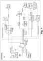
Fig. 1 is a schematic diagram of an embodiment of a control system in accordance with this disclosure, schematically showing input data flow; and -
Fig. 2 is a schematic diagram of the embodiment ofFig. 1 , additionally showing feedback flow. - Reference will now be made to the drawings wherein like reference numerals identify similar structural features or aspects of the subject disclosure. For purposes of explanation and illustration, and not limitation, an illustrative view of an embodiment of a system in accordance with the disclosure is shown in
Fig. 1 and is designated generally byreference character 100. Other embodiments and/or aspects of this disclosure are shown inFig. 2 . - Referring to
Figs. 1 and2 , acontrol system 100 for a hybrid electric powerplant of an aircraft includes aheat engine controller 101 configured to receive one or more power settings (e.g., throttle and/or propeller setting, e.g., power lever angle (PLA) from a power lever 102) output and to determine a heat engine setting (e.g., a torque) and an electric motor setting (e.g., a torque). Theheat engine controller 101 can be configured to use the heat engine setting to control aheat engine system 103 as a function of the heat engine setting to control torque output by aheat engine 105. Theheat engine controller 101 is configured to output the electric motor setting. - The
system 100 includes anelectric motor controller 107 that is operatively connected to theheat engine controller 101. Theelectric motor controller 107 is configured to receive the electric motor engine setting from theheat engine controller 101 and is configured to control anelectric motor system 109, 111 (e.g., a battery management system and/or electric motor 111) as a function of the electric motor setting to control torque output by anelectric motor 111. - The
system 100 includes asystem protection module 101a that can be part of or connected to theheat engine controller 101 and is configured to provide one or more protection commands to directly control one or more heatengine protection systems 113 and one or more electricmotor protection systems 115. Thesystem protection module 101a can directly or indirectly connected to any suitable protection systems or other suitable control systems of any system of the powerplant to provide protection control thereto. Thesystem protection module 101a can be integrated with and/or independent of theheat engine controller 101 in any suitable manner. - The
system 100 includes an electricmotor protection module 107a that is part of theelectric motor controller 107 and configured to provide one or more protection commands to directly control one or more electricmotor protection systems 115. In certain embodiments, thesystem protection module 101a can be configured to provide powertrain level protection for the electric motor system and the electricmotor protection module 107a can be configured to provide lane level protection to the electric motor system. - For example, the powertrain level protection can include uncontrollable high thrust protection (e.g., such that the
system protection module 101a shuts down power to theelectric motor 111 if thrust is above a threshold or determined to be out of control of the electric motor controller 107). In certain embodiments, the lane level protection can include overspeed, overcurrent, and/or over temperature protection (e.g., such that the electricmotor protection module 107a shuts down power to theelectric motor 111 if speed, current to theelectric motor 111, and/or motor and/or battery temperature are above a threshold). Thesystem protection module 101a can also be configured to provide heat engine overspeed and/or shaft shear protection in certain embodiments (e.g., such that the system protection module shuts off fuel flow to theheat engine 105 if speed and/or a strain on a shaft is above a threshold). Any other suitable protection types, system and/or lane level, e.g., as appreciated by those having ordinary skill in the art, are contemplated herein. - In certain embodiments, the
heat engine controller 101 can be configured to determine a propeller setting (e.g., based on a condition lever angle (CLA) or a selected propeller mode from a mode selector 117) and to use the propeller setting to control a propeller control system 119 (e.g., a PCU) as a function of the propeller setting to control a pitch of a propeller (e.g., via a hydraulic pitch control as appreciated by those having ordinary skill in the art in view of this disclosure). Thesystem protection module 101a can be configured to provide one or more protection commands to directly control one or morepropeller protection systems 123, for example. - The
heat engine controller 101 and/or thesystem protection module 101a can be operatively connected to each of theelectric motor 111, theheat engine 105, and/or thepropeller system 121 to receive feedback therefrom to provide control thereto (directly or indirectly) and/or protection control thereto (directly or indirectly). The electricmotor protection module 107a can be operatively connected to the electric motor 111 (directly or indirectly) to receive electric motor feedback therefrom to provide protection control for theelectric motor 111. Any suitable feedback, e.g., from any suitable sensor, is contemplated herein. - The
electric motor system 109 can include a battery management system (BMS), e.g., as shown. In certain embodiments, the electricmotor protection system 115 can include an electrical cutoff mechanism (e.g., a controllable contactor) disposed between the BMS 109 and theelectric motor 111. The electrical cutoff mechanism (e.g., a switch) can be configured to be controlled by the electricmotor protection module 107a and/ thesystem protection module 101a to cut off electrical energy to theelectric motor 111 in a protection state, for example (e.g., overthrust, overcurrent, overspeed, etc.). - The
heat engine system 103 is a fuel control unit, e.g., as shown, for example. In certain embodiments, the heatengine protection system 113 can include a fuel shutoff valve (e.g., an overspeed valve) configured to be controlled by thesystem protection module 101a to cut off fuel flow to thefuel control unit 103 in a protection state, for example. - The
propeller control system 119 can be a propeller control unit, e.g., as shown that can be configured to control a pitch of the propeller 121 (e.g., via a hydraulic oil system or any other suitable system). Thepropeller protection system 123 can include a feathering valve, e.g., as shown, configured to be controlled by thesystem protection module 101a to coarsen the pitch of (e.g., feather) thepropeller 121 in a protection state, for example. Thepropeller protection system 123 can be configured to protect against propeller overspeed, propeller overtorque, and/or inadvertent operation in reverse propeller angle, for example. Any other suitable protection systems are contemplated herein. - In certain embodiments, the
electric motor controller 107 and/or the electricmotor protection module 107a can be operatively connected to theheat engine controller 101 to provide controller operation feedback and/or respective system feedback to the heat engine controller. Theheat engine controller 101 can include a thrust control module configured to divide a thrust command into an electric torque command for use by theelectric motor controller 107 and a heat engine torque command for use by theheat engine controller 101 such that the electric engine settings include the electric torque command and the heat engine settings include a heat engine torque command. In certain embodiments, theheat engine controller 101 can include a propeller control module configured to receive a propeller mode setting (e.g., quite mode, cruise mode, max power mode) and to output a propeller setting (e.g., to the propeller control system 119) to achieve the selected propeller mode. - The
heat engine controller 101 can be configured to receive feedback from the electricmotor protection module 107a for detection and/or reporting of a problem with the electric motor system to diagnose a cause and/or resolve the problem, e.g., by controlling a different system (e.g., the heat engine system). - In certain embodiments, the heat motor feedback, the electric motor feedback, and/or the propeller system feedback can include a torque value and/or a speed value. In certain embodiments, the heat engine feedback includes a temperature value for detecting heat engine fire. Any other suitable feedback is contemplated herein.
- In certain embodiments, ambient air data can be input to the
heat engine controller 101 and/or to thesystem protection module 101a, e.g., from one or moreair data sensors 125. For example, theheat engine controller 101 and/or thesystem protection module 101a can be configured to use the ambient air data for control and/or protection control, respectively. In certain embodiments, air data can be provided to theelectric motor controller 107 and/or the electricmotor protection controller 107a. Any other suitable data flow and/or feedback flow is contemplated herein. - In certain embodiments, the
heat engine controller 101 can be configured to output one or more values of the feedback and/or air data to an aircraft cockpit display (e.g., battery state of charge, electric motor torque, heat engine torque, electric motor temperature, heat engine temperature), for example. Any suitable display and any suitable values are contemplated herein. - In certain embodiments, the heat engine controller can be located in the fuselage of the aircraft and the electric motor controller can be located in the fuselage, wing, or HEP. In certain embodiments, the heat engine controller can be disposed within an avionics stack in a cockpit of the aircraft. Any suitable locations are contemplated herein.
- Certain embodiments do not include or require a separate thrust controller for splitting thrust commands between the heat engine controller and the electric motor controller as the heat engine controller (e.g., an ECU). Certain embodiments can provide flexibility for controlling propeller state as a function of ambient conditions and an input mode (e.g., quiet mode). For example, in certain embodiments, there is no propeller electronic controller (PEC) needed to decode a mode or CLA command as the heat engine controller can perform this function.
- The system protection module (e.g., part of the heat engine controller) can also handle the protection for the thermal torque lane as well as the propeller system in certain embodiments. In certain embodiments, the system protection module (e.g., part of the heat engine controller) can also handle HEP level protection only for electric motor system (e.g., shut down due to high thrust condition, which can down the entire HEP), and all other protections can be performed by the electric motor protection module. Embodiments can reduce the number of controllers in the
overall system 100, reducing size and weight of the system while maintaining functionality. - In certain embodiments, the system can utilize a consolidated power command from the aircraft via a single lever (by setting a desired mode), the heat engine controller can be a primary command receiver, there may be no direct power command signal to the electric motor controller, there may be separate propeller control from engine control, and there may be no mechanical disconnect.
- The heat engine controlled (e.g., an engine control unit (ECU)) can be the power and thrust command controller of the hybrid electric propulsion (HEP) system which includes an electric motor, heat motor, and a propeller system. The ECU can receive the pilot thrust/power command in the form of a Power Lever Angle (PLA) signal, the pilot commanded propeller speed in the form of the PLA signal, a propeller select signal to determine the propeller operation mode desired by the pilot, and the ambient air conditions from the aircraft signals, for example. The ECU can use the aircraft signals to determine the power demand for the total HEP system and can split the demand into the commands to the electric motor (eM), heat motor (hM), and propeller systems. The speed governing of the HEP could be performed by the propeller control system or the hM control system.
- Using received aircraft data, the ECU can translate the power command, ambient air conditions, and propeller mode select to determine the propeller blade angle (beta) and the power split between the hM and eM. Ambient air conditions can affect the thrust generated by the propeller and the hM performance. The ECU can have performance maps and models of the propeller and hM performance to determine the optimum motor and propeller operating points to meet the thrust command with the given propeller select mode. The ECU can manage interactions between the motors and the propeller system such as torque spikes. After calculating the torque split and the propeller output speed, the ECU can send the fuel flow command to a Fuel Control Unit (FCU) to manage hM torque (Q_hm), the electric powertrain controller (EPC) can receive the torque command (Q_eM) from the ECU, and the ECU can send the beta command to the propeller control unit (PCU) to control the blade angle and ultimately the speed of the propeller speed. The ECU will also relay the overall operation of thermal engine effectors to meet the aircraft servicing needs (electrical power, bleed air, hydraulic power, etc.).
- The ECU can send the beta command to the PCU to drive the requested propeller speed. The cockpit can also send a beta pitch lock signal to the ECU and PCU, for example (e.g., from a manual input in the cockpit activated by a pilot). The beta lock can provide an indication when the PLA is in the reverse beta region. In the PCU, this can hydraulically unlock the region of the PCU to allow pressurization to the reverse beta blade angle range. In the ECU, it can allow a cross-reference with the PLA to determine whether the propeller system is permitted to enter the reverse beta region. Other propeller functions can be located in the ECU, for example. Any split of functionality between the PCU and the ECU are contemplated herein.
- The ECU can include separate electronics to perform the protection functions to protect against propeller overspeed, propeller overtorque, inadvertent reverse thrust/power, in-flight shutdown (IFSD), inability to autofeather, thermal engine overspeed (which can alternatively or additionally be implemented by mechanical protection means), thermal engine shaft shear (which can alternatively or additionally be implemented by mechanical protection means), and/or uncontrollable high thrust (UHT).
- All parameters affecting a control and protection function (e.g. speed, torque, propeller blade angle, etc.) can have completely independent means of measurement (e.g. multiple probes or segregated means of measurement). For parameters from aircraft systems, similar requirements can be used to ensure that no single failure can result in a catastrophic or hazardous safety case.
- The ECU can have control over an overspeed valve (OSV), a battery contactor, and a feathering valve. The OSV can provide a fuel shutoff means upstream of the fuel control unit (FCU) and can be used to shutdown the hM when required. The feathering valve can have the authority to coarsen the blade angle to "grab more air" to push the propeller out of certain critical operating areas. The battery contactor can cut off current from the battery system to the electric motor.
- The propeller, thermal engine, and at least some powertrain safety functions can be contained in the system protection module (e.g., ECU protection processor (ECU-PP)). Propeller overspeed, auto feather, and reverse beta functions can be propeller protection functions contained the ECU-PP, for example. Thermal engine overspeed and shaft shear protection can be located in the ECU-PP, or designed in the thermal engine mechanical design, for example. The electric motor protection module (e.g., EPC-PP) can perform the electric motor control-level protection functions, e.g., overspeed, overcurrent, and/or overtemperature protection. The ECU-PP can perform powertrain-level protection functions such as uncontrollable high-thrust protection. Ambient air data, each power lane's torque and speed data, and the propeller operating conditions (speed, torque, and propeller angle) can be provided to the ECU-PP where the processor can compute the total output thrust.
- The ECU-PP can have the authority to shutdown each power lane and feather the propeller, for example. Protection means can be implemented to protect against hM failure cases resulting in engine and aircraft level safety cases. For example, in the event of an initiating event with the potential to lead to a hazardous or catastrophic event, the ECU-PP can cut off fuel flow using the OSV. Heat motor protection functions may include protection against non-containment of high-energy debris, shaft shear protection, overspeed protection, and/or protection against uncontrollable high thrust. Uncontrollable high thrust protection can involve understanding propeller and engine and motor interactions as they create thrust for the aircraft. The protection means could be implemented to both feather and shutdown the engine, for example. UHT protection may be required at high-power conditions such as takeoff in certain implementations. If the propeller blades were feathered at high power, it could lead to an overtorque condition. As a result, during high-power shutdown, the ECU-PP may sequence the motor shutoff first prior to feathering the propeller, for example.
- For the propeller system, independent protection means for the propeller system may be utilized. The protection means for propeller system can depend on the potential hazard being mitigated. In the event of an in-flight shutdown (IFSD), the propeller can be feathered to reduce the drag. Inability to feather after an IFSD on takeoff or climb could be potentially catastrophic. Protection means against a propeller overspeed and potential blade separation can also be provided by driving the propeller blade angle towards feather, coarsening the blade. By coarsening the blade angle, the propeller "grabs" more air and slows down as the rotational energy is transferred to torque. Protection against inadvertent operation in reverse beta region can be implemented in the ECU-PP as well, for example.
- Certain embodiments can provide a reduction in pilot workload for the start sequence. The HEP control system can automate starting functions to coordinate between the cockpit interface, the electric motor, and the heat engine. Single lever power control can greatly simplify the number of required inputs from the pilot and the required indications to monitor the engine start-up sequence. Certain embodiments can allow for reduction in pilot workload for most phases of flight. For example, single lever power control with the "mode select" can allow the pilot to control the propeller, electric motor, and thermal engine running speed through these two inputs, as opposed to two levers (e.g., a PLA and a CLA input).
- Integrating the control into a single unit, e.g., the ECU, can allow for greater access to data for the use of trend monitoring, maintenance diagnosis, and repair tools. The ECU can be able to monitor the operating data of all elements of the propulsion system to determine potential reductions in performance or negative trends in reliability. Certain embodiments can centralize control and protection functions to provide a system that can be easier to update and upgrade. Changes to the system can be performed in a more central place as opposed to updating each controller unit.
- Any controllers and/or modules described above can include any suitable hardware module(s) and/or software module(s). Any suitable controllers and/or modules can be independent of each other or can be hosted together and/or integrated together in any suitable manner (e.g., various software modules hosted on the same computer hardware).
- As will be appreciated by those skilled in the art, aspects of the present disclosure may be embodied as a system, method or computer program product. Accordingly, aspects of this disclosure may take the form of an entirely hardware embodiment, an entirely software embodiment (including firmware, resident software, micro-code, etc.), or an embodiment combining software and hardware aspects, all possibilities of which can be referred to herein as a "circuit," "module," or "system." A "circuit," "module," or "system" can include one or more portions of one or more separate physical hardware and/or software components that can together perform the disclosed function of the "circuit," "module," or "system", or a "circuit," "module," or "system" can be a single self-contained unit (e.g., of hardware and/or software). Furthermore, aspects of this disclosure may take the form of a computer program product embodied in one or more computer readable medium(s) having computer readable program code embodied thereon.
- Any combination of one or more computer readable medium(s) may be utilized. The computer readable medium may be a computer readable signal medium or a computer readable storage medium. A computer readable storage medium may be, for example, but not limited to, an electronic, magnetic, optical, electromagnetic, infrared, or semiconductor system, apparatus, or device, or any suitable combination of the foregoing. More specific examples (a non-exhaustive list) of the computer readable storage medium would include the following: an electrical connection having one or more wires, a portable computer diskette, a hard disk, a random access memory (RAM), a read-only memory (ROM), an erasable programmable read-only memory (EPROM or Flash memory), an optical fiber, a portable compact disc read-only memory (CD-ROM), an optical storage device, a magnetic storage device, or any suitable combination of the foregoing. In the context of this document, a computer readable storage medium may be any tangible medium that can contain, or store a program for use by or in connection with an instruction execution system, apparatus, or device.
- A computer readable signal medium may include a propagated data signal with computer readable program code embodied therein, for example, in baseband or as part of a carrier wave. Such a propagated signal may take any of a variety of forms, including, but not limited to, electro-magnetic, optical, or any suitable combination thereof. A computer readable signal medium may be any computer readable medium that is not a computer readable storage medium and that can communicate, propagate, or transport a program for use by or in connection with an instruction execution system, apparatus, or device.
- Program code embodied on a computer readable medium may be transmitted using any appropriate medium, including but not limited to wireless, wireline, optical fiber cable, RF, etc., or any suitable combination of the foregoing.
- Computer program code for carrying out operations for aspects of this disclosure may be written in any combination of one or more programming languages, including an object oriented programming language such as Java, Smalltalk, C++ or the like and conventional procedural programming languages, such as the "C" programming language or similar programming languages. The program code may execute entirely on the user's computer, partly on the user's computer, as a stand-alone software package, partly on the user's computer and partly on a remote computer or entirely on the remote computer or server. In the latter scenario, the remote computer may be connected to the user's computer through any type of network, including a local area network (LAN) or a wide area network (WAN), or the connection may be made to an external computer (for example, through the Internet using an Internet Service Provider).
- Aspects of the this disclosure may be described above with reference to flowchart illustrations and/or block diagrams of methods, apparatus (systems) and computer program products according to embodiments of this disclosure. It will be understood that each block of any flowchart illustrations and/or block diagrams, and combinations of blocks in any flowchart illustrations and/or block diagrams, can be implemented by computer program instructions. These computer program instructions may be provided to a processor of a general purpose computer, special purpose computer, or other programmable data processing apparatus to produce a machine, such that the instructions, which execute via the processor of the computer or other programmable data processing apparatus, create means for implementing the functions/acts specified in any flowchart and/or block diagram block or blocks.
- These computer program instructions may also be stored in a computer readable medium that can direct a computer, other programmable data processing apparatus, or other devices to function in a particular manner, such that the instructions stored in the computer readable medium produce an article of manufacture including instructions which implement the function/act specified in the flowchart and/or block diagram block or blocks.
- The computer program instructions may also be loaded onto a computer, other programmable data processing apparatus, or other devices to cause a series of operational steps to be performed on the computer, other programmable apparatus or other devices to produce a computer implemented process such that the instructions which execute on the computer or other programmable apparatus provide processes for implementing the functions/acts specified herein.
- Those having ordinary skill in the art understand that any numerical values disclosed herein can be exact values or can be values within a range. Further, any terms of approximation (e.g., "about", "approximately", "around") used in this disclosure can mean the stated value within a range. For example, in certain embodiments, the range can be within (plus or minus) 20%, or within 10%, or within 5%, or within 2%, or within any other suitable percentage or number as appreciated by those having ordinary skill in the art (e.g., for known tolerance limits or error ranges).
- The articles "a", "an", and "the" as used herein and in the appended claims are used herein to refer to one or to more than one (i.e., to at least one) of the grammatical object of the article unless the context clearly indicates otherwise. By way of example, "an element" means one element or more than one element.
- The phrase "and/or," as used herein in the specification and in the claims, should be understood to mean "either or both" of the elements so conjoined, i.e., elements that are conjunctively present in some cases and disjunctively present in other cases. Multiple elements listed with "and/or" should be construed in the same fashion, i.e., "one or more" of the elements so conjoined. Other elements may optionally be present other than the elements specifically identified by the "and/or" clause, whether related or unrelated to those elements specifically identified. Thus, as a non-limiting example, a reference to "A and/or B", when used in conjunction with open-ended language such as "comprising" can refer, in one embodiment, to A only (optionally including elements other than B); in another embodiment, to B only (optionally including elements other than A); in yet another embodiment, to both A and B (optionally including other elements); etc.
- As used herein in the specification and in the claims, "or" should be understood to have the same meaning as "and/or" as defined above. For example, when separating items in a list, "or" or "and/or" shall be interpreted as being inclusive, i.e., the inclusion of at least one, but also including more than one, of a number or list of elements, and, optionally, additional unlisted items. Only terms clearly indicated to the contrary, such as "only one of" or "exactly one of," or, when used in the claims, "consisting of," will refer to the inclusion of exactly one element of a number or list of elements. In general, the term "or" as used herein shall only be interpreted as indicating exclusive alternatives (i.e., "one or the other but not both") when preceded by terms of exclusivity, such as "either," "one of," "only one of," or "exactly one of."
- Any suitable combination(s) of any disclosed embodiments and/or any suitable portion(s) thereof are contemplated herein as appreciated by those having ordinary skill in the art in view of this disclosure.
- The embodiments of the present disclosure, as described above and shown in the drawings, provide for improvement in the art to which they pertain. While the subject disclosure includes reference to certain embodiments, those skilled in the art will readily appreciate that changes and/or modifications may be made thereto without departing from the scope of the subject disclosure defined by the appended claims.
Claims (15)
- A control system (100) for a hybrid electric powerplant of an aircraft, comprising:a heat engine controller (101) configured to receive one or more power command settings from a power lever (102) and to determine a heat engine setting and an electric motor setting, the heat engine controller (101) configured to use the heat engine setting to control a fuel control unit (103) of a heat engine (105) as a function of the heat engine setting by sending a fuel flow command to the fuel control unit (103) to control torque output by the heat engine (105), wherein the heat engine controller (101) is configured to output the electric motor setting;an electric motor controller (107) operatively connected to the heat engine controller (101), the electric motor controller (107) configured to receive the electric motor setting from the heat engine controller (101) and to control an electric motor system (109, 111) as a function of the electric motor setting to control torque output by an electric motor (111);a system protection module (101a) that is part of or connected to the heat engine controller (101) and configured to provide one or more protection commands to directly control one or more heat engine protection systems (113) and one or more electric motor protection systems (115); andan electric motor protection module (107a) that is part of the electric motor controller (107) and configured to provide one or more protection commands to directly control the one or more electric motor protection systems (115).
- The system (100) of claim 1, wherein the electric motor protection module (107a) is configured to provide lane level protection to the electric motor system (109, 111), optionally wherein the lane level protection includes overspeed, overcurrent, and/or over temperature protection.
- The system (100) of claim 1 or 2, wherein the heat engine controller (101) and/or the system protection module (101a) is operatively connected to each of the electric motor (111), the heat engine (105), and/or a propeller system (121) to receive feedback therefrom to provide control thereto and/or protection control thereto, wherein the electric motor protection module (107a) is operatively connected to the electric motor (111) to receive electric motor feedback therefrom to provide protection control for the electric motor (111).
- The system (100) of claim 3, wherein:the heat engine feedback includes a temperature value for detecting heat engine fire; and/orthe heat motor feedback, the electric motor feedback, and/or the propeller system feedback includes a torque value and/or a speed value.
- The system (100) of any preceding claim, wherein the electric motor system (109, 111) includes a battery management system, BMS, (109), wherein the electric motor protection system (115) includes an electrical cutoff mechanism disposed between the BMS (109) and the electric motor (111), the electrical cutoff mechanism (115) being configured to be controlled by the electric motor protection module (107a) and the system protection module (101a) to cut off electrical energy to the electric motor (111) in a protection state.
- The system (100) of any preceding claim, wherein the heat engine controller (101) is configured to receive feedback from the electric motor protection module (107a) for detection and/or reporting of a problem with the electric motor system (109, 111) to diagnose a cause and/or resolve the problem by controlling a different system.
- The system (100) of any preceding claim, wherein the system protection module (101a) is configured to provide powertrain level protection for the electric motor system (109, 111), optionally wherein the powertrain level protection includes uncontrollable high thrust protection.
- The system (100) of any preceding claim, wherein the system protection module (101a) is configured to provide:heat engine overspeed and/or shaft shear protection; and/orone or more protection commands to directly control one or more propeller protection systems (123).
- The system (100) of any preceding claim, wherein the heat engine controller (101) is configured to determine a propeller setting and to use the propeller setting to control a propeller control system (119) as a function of the propeller setting.
- The system (100) of claim 9, wherein the propeller control system (119) is a propeller control unit configured to control a pitch of a propeller (121), and the propeller protection system (123) includes a feathering valve configured to be controlled by the system protection module (101a) to coarsen the propeller pitch in a protection state.
- The system (100) of any preceding claim, wherein the heat engine protection system (113) includes a fuel shutoff valve configured to be controlled by the system protection module (101a) to cut off fuel flow to the fuel control unit (103) in a protection state.
- The system (100) of any preceding claim, wherein the electric motor controller (107) and/or the electric motor protection module (107a) is/are operatively connected to the heat engine controller (101) to provide controller operation feedback and/or respective system feedback to the heat engine controller (101).
- The system (100) of any preceding claim, wherein the heat engine controller (101) includes:a thrust control module configured to divide a thrust command into an electric torque command for use by the electric motor controller (107) and a heat engine torque command for use by the heat engine controller (101) such that the electric engine settings include the electric torque command and the heat engine settings include a heat engine torque command; and/ora propeller control module configured to receive a propeller mode setting and to output a propeller setting to achieve the selected propeller mode.
- The system (100) of any preceding claim, wherein ambient air data is input to the heat engine controller (101) and/or to the system protection module (101a), wherein the heat engine controller (101) and/or the system protection module (101a) are configured to use the ambient air data for control and/or protection control, respectively.
- A method for controlling a hybrid electric powerplant of an aircraft, comprising:receiving one or more power command settings from a power lever (102) of the aircraft at a heat engine controller (101);controlling an electric motor (111) with an electric motor controller (107);controlling a heat engine (105) with the heat engine controller (101) by sending a fuel flow command from the heat engine controller (101) to a fuel control unit of the heat engine (105) to control torque output by the heat engine (105);providing an electric motor torque command to the electric motor controller (107) from the heat engine controller (101);providing overspeed or overtorque protection to the electric motor (111) with an electric motor protection module (107a) that is part of the electric motor controller (107);providing overspeed or overtorque protection to the heat engine (105) with a system protection module (101a) that is part of or connected to the heat engine controller (101); andproviding uncontrollable thrust protection for the electric motor (111) using the system protection module (101a).
Applications Claiming Priority (1)
| Application Number | Priority Date | Filing Date | Title |
|---|---|---|---|
| US16/875,911 US11760495B2 (en) | 2020-05-15 | 2020-05-15 | Control systems for hybrid electric power plants |
Publications (2)
| Publication Number | Publication Date |
|---|---|
| EP3909856A1 EP3909856A1 (en) | 2021-11-17 |
| EP3909856B1 true EP3909856B1 (en) | 2024-12-18 |
Family
ID=75936892
Family Applications (1)
| Application Number | Title | Priority Date | Filing Date |
|---|---|---|---|
| EP21174143.4A Active EP3909856B1 (en) | 2020-05-15 | 2021-05-17 | Control systems for hybrid electric power plants |
Country Status (4)
| Country | Link |
|---|---|
| US (1) | US11760495B2 (en) |
| EP (1) | EP3909856B1 (en) |
| CA (1) | CA3119006A1 (en) |
| PL (1) | PL3909856T3 (en) |
Families Citing this family (3)
| Publication number | Priority date | Publication date | Assignee | Title |
|---|---|---|---|---|
| US11845551B2 (en) * | 2021-02-26 | 2023-12-19 | Beta Air, Llc | Methods and system for estimating percentage torque produced by a propulsor configured for use in an electric aircraft |
| US11965424B2 (en) | 2022-06-21 | 2024-04-23 | General Electric Company | Electronic overspeed protection system and method |
| US20240113513A1 (en) * | 2022-10-04 | 2024-04-04 | Pratt & Whitney Canada Corp. | Overspeed and/or overtorque protection for hybrid electric aircraft propulsion system |
Citations (2)
| Publication number | Priority date | Publication date | Assignee | Title |
|---|---|---|---|---|
| US20120209456A1 (en) * | 2011-02-15 | 2012-08-16 | Government Of The United States, As Represented By The Secretary Of The Air Force | Parallel Hybrid-Electric Propulsion Systems for Unmanned Aircraft |
| EP3927620A1 (en) * | 2019-04-25 | 2021-12-29 | Pratt & Whitney Canada Corp. | Control systems for hybrid electric powerplants |
Family Cites Families (4)
| Publication number | Priority date | Publication date | Assignee | Title |
|---|---|---|---|---|
| JP2017527059A (en) * | 2014-08-29 | 2017-09-14 | ズーナム エアロ,インコーポレイテッド | System and method for implementing a regional air traffic network using a hybrid electric airplane |
| US10006375B1 (en) | 2017-07-11 | 2018-06-26 | General Electric Company | Propulsion system for an aircraft |
| US11015480B2 (en) * | 2018-08-21 | 2021-05-25 | General Electric Company | Feed forward load sensing for hybrid electric systems |
| US11332256B2 (en) * | 2018-08-21 | 2022-05-17 | General Electric Company | Fault tolerant hybrid electric propulsion system for an aerial vehicle |
-
2020
- 2020-05-15 US US16/875,911 patent/US11760495B2/en active Active
-
2021
- 2021-05-17 CA CA3119006A patent/CA3119006A1/en active Pending
- 2021-05-17 PL PL21174143.4T patent/PL3909856T3/en unknown
- 2021-05-17 EP EP21174143.4A patent/EP3909856B1/en active Active
Patent Citations (2)
| Publication number | Priority date | Publication date | Assignee | Title |
|---|---|---|---|---|
| US20120209456A1 (en) * | 2011-02-15 | 2012-08-16 | Government Of The United States, As Represented By The Secretary Of The Air Force | Parallel Hybrid-Electric Propulsion Systems for Unmanned Aircraft |
| EP3927620A1 (en) * | 2019-04-25 | 2021-12-29 | Pratt & Whitney Canada Corp. | Control systems for hybrid electric powerplants |
Also Published As
| Publication number | Publication date |
|---|---|
| PL3909856T3 (en) | 2025-03-10 |
| US20210354837A1 (en) | 2021-11-18 |
| US11760495B2 (en) | 2023-09-19 |
| EP3909856A1 (en) | 2021-11-17 |
| CA3119006A1 (en) | 2021-11-15 |
Similar Documents
| Publication | Publication Date | Title |
|---|---|---|
| EP3927620B1 (en) | Control systems for hybrid electric powerplants | |
| EP3909857B1 (en) | Control systems for hybrid electric power plants | |
| EP3909856B1 (en) | Control systems for hybrid electric power plants | |
| EP3936712B1 (en) | Hybrid electric powerplant (hep) control architecture | |
| EP3613674B1 (en) | Fault tolerant hybrid electric propulsion system for an aerial vehicle | |
| US20200277064A1 (en) | Degraded mode operation of hybrid electric propulsion systems | |
| EP2915749B1 (en) | System and method for operating a multi-engine aircraft in an auxiliary power unit mode | |
| WO2017015341A1 (en) | Control system for rotorcraft in-flight engine restarting | |
| US20180065738A1 (en) | Autorotation initiation system | |
| EP4101755B1 (en) | Supplemental engine power control | |
| US20220009651A1 (en) | Interactive electronic checklists for autonomous aircraft | |
| EP4019396B1 (en) | System and method for detecting propeller malfunction | |
| CN112173169A (en) | Automatic checking method for engine power of three-engine helicopter | |
| EP3909858B1 (en) | Protection functions | |
| US9522740B2 (en) | Method and a device for protecting an overspeeding rotorcraft engine | |
| US20240175400A1 (en) | Hybrid-electric propulsion system equipped with a coupler for switching between modes of operation | |
| US20240377838A1 (en) | Method and device for entering and exiting an economy operating mode for a twin-engine aircraft | |
| EP4155212B1 (en) | Aircraft hybrid propulsion system | |
| EP4480826A1 (en) | Method and system for mitigating an electric motor fault in an aircraft power plant | |
| EP4350135A2 (en) | Overspeed and/or overtorque protection for hybrid electric aircraft propulsion system | |
| CN118774989A (en) | A method and system for protecting a power turbine from overspeed in a single-engine unmanned helicopter engine |
Legal Events
| Date | Code | Title | Description |
|---|---|---|---|
| PUAI | Public reference made under article 153(3) epc to a published international application that has entered the european phase |
Free format text: ORIGINAL CODE: 0009012 |
|
| STAA | Information on the status of an ep patent application or granted ep patent |
Free format text: STATUS: THE APPLICATION HAS BEEN PUBLISHED |
|
| AK | Designated contracting states |
Kind code of ref document: A1 Designated state(s): AL AT BE BG CH CY CZ DE DK EE ES FI FR GB GR HR HU IE IS IT LI LT LU LV MC MK MT NL NO PL PT RO RS SE SI SK SM TR |
|
| B565 | Issuance of search results under rule 164(2) epc |
Effective date: 20211013 |
|
| STAA | Information on the status of an ep patent application or granted ep patent |
Free format text: STATUS: REQUEST FOR EXAMINATION WAS MADE |
|
| 17P | Request for examination filed |
Effective date: 20220321 |
|
| RBV | Designated contracting states (corrected) |
Designated state(s): AL AT BE BG CH CY CZ DE DK EE ES FI FR GB GR HR HU IE IS IT LI LT LU LV MC MK MT NL NO PL PT RO RS SE SI SK SM TR |
|
| STAA | Information on the status of an ep patent application or granted ep patent |
Free format text: STATUS: EXAMINATION IS IN PROGRESS |
|
| 17Q | First examination report despatched |
Effective date: 20230328 |
|
| GRAP | Despatch of communication of intention to grant a patent |
Free format text: ORIGINAL CODE: EPIDOSNIGR1 |
|
| STAA | Information on the status of an ep patent application or granted ep patent |
Free format text: STATUS: GRANT OF PATENT IS INTENDED |
|
| RIC1 | Information provided on ipc code assigned before grant |
Ipc: B64D 27/02 20060101ALN20240703BHEP Ipc: F02C 9/28 20060101ALI20240703BHEP Ipc: B64D 31/00 20060101ALI20240703BHEP Ipc: B64D 27/24 20060101AFI20240703BHEP |
|
| INTG | Intention to grant announced |
Effective date: 20240712 |
|
| GRAS | Grant fee paid |
Free format text: ORIGINAL CODE: EPIDOSNIGR3 |
|
| GRAA | (expected) grant |
Free format text: ORIGINAL CODE: 0009210 |
|
| STAA | Information on the status of an ep patent application or granted ep patent |
Free format text: STATUS: THE PATENT HAS BEEN GRANTED |
|
| AK | Designated contracting states |
Kind code of ref document: B1 Designated state(s): AL AT BE BG CH CY CZ DE DK EE ES FI FR GB GR HR HU IE IS IT LI LT LU LV MC MK MT NL NO PL PT RO RS SE SI SK SM TR |
|
| REG | Reference to a national code |
Ref country code: CH Ref legal event code: EP |
|
| REG | Reference to a national code |
Ref country code: DE Ref legal event code: R096 Ref document number: 602021023438 Country of ref document: DE |
|
| REG | Reference to a national code |
Ref country code: IE Ref legal event code: FG4D |