EP3905944B1 - Positioning a tube in a lumen via transillumination - Google Patents
Positioning a tube in a lumen via transillumination Download PDFInfo
- Publication number
- EP3905944B1 EP3905944B1 EP19845684.0A EP19845684A EP3905944B1 EP 3905944 B1 EP3905944 B1 EP 3905944B1 EP 19845684 A EP19845684 A EP 19845684A EP 3905944 B1 EP3905944 B1 EP 3905944B1
- Authority
- EP
- European Patent Office
- Prior art keywords
- tube
- light
- optical fiber
- distal end
- emitting
- Prior art date
- Legal status (The legal status is an assumption and is not a legal conclusion. Google has not performed a legal analysis and makes no representation as to the accuracy of the status listed.)
- Active
Links
Images


Classifications
-
- A—HUMAN NECESSITIES
- A61—MEDICAL OR VETERINARY SCIENCE; HYGIENE
- A61B—DIAGNOSIS; SURGERY; IDENTIFICATION
- A61B1/00—Instruments for performing medical examinations of the interior of cavities or tubes of the body by visual or photographical inspection, e.g. endoscopes; Illuminating arrangements therefor
- A61B1/00163—Optical arrangements
- A61B1/00165—Optical arrangements with light-conductive means, e.g. fibre optics
- A61B1/0017—Details of single optical fibres, e.g. material or cladding
-
- A—HUMAN NECESSITIES
- A61—MEDICAL OR VETERINARY SCIENCE; HYGIENE
- A61B—DIAGNOSIS; SURGERY; IDENTIFICATION
- A61B5/00—Measuring for diagnostic purposes; Identification of persons
- A61B5/0059—Measuring for diagnostic purposes; Identification of persons using light, e.g. diagnosis by transillumination, diascopy, fluorescence
-
- A—HUMAN NECESSITIES
- A61—MEDICAL OR VETERINARY SCIENCE; HYGIENE
- A61B—DIAGNOSIS; SURGERY; IDENTIFICATION
- A61B5/00—Measuring for diagnostic purposes; Identification of persons
- A61B5/06—Devices, other than using radiation, for detecting or locating foreign bodies ; Determining position of diagnostic devices within or on the body of the patient
- A61B5/061—Determining position of a probe within the body employing means separate from the probe, e.g. sensing internal probe position employing impedance electrodes on the surface of the body
-
- A—HUMAN NECESSITIES
- A61—MEDICAL OR VETERINARY SCIENCE; HYGIENE
- A61J—CONTAINERS SPECIALLY ADAPTED FOR MEDICAL OR PHARMACEUTICAL PURPOSES; DEVICES OR METHODS SPECIALLY ADAPTED FOR BRINGING PHARMACEUTICAL PRODUCTS INTO PARTICULAR PHYSICAL OR ADMINISTERING FORMS; DEVICES FOR ADMINISTERING FOOD OR MEDICINES ORALLY; BABY COMFORTERS; DEVICES FOR RECEIVING SPITTLE
- A61J15/00—Feeding-tubes for therapeutic purposes
- A61J15/0003—Nasal or oral feeding-tubes, e.g. tube entering body through nose or mouth
-
- A—HUMAN NECESSITIES
- A61—MEDICAL OR VETERINARY SCIENCE; HYGIENE
- A61M—DEVICES FOR INTRODUCING MEDIA INTO, OR ONTO, THE BODY; DEVICES FOR TRANSDUCING BODY MEDIA OR FOR TAKING MEDIA FROM THE BODY; DEVICES FOR PRODUCING OR ENDING SLEEP OR STUPOR
- A61M25/00—Catheters; Hollow probes
- A61M25/0021—Catheters; Hollow probes characterised by the form of the tubing
- A61M25/0023—Catheters; Hollow probes characterised by the form of the tubing by the form of the lumen, e.g. cross-section, variable diameter
- A61M25/0026—Multi-lumen catheters with stationary elements
- A61M25/003—Multi-lumen catheters with stationary elements characterized by features relating to least one lumen located at the distal part of the catheter, e.g. filters, plugs or valves
-
- F—MECHANICAL ENGINEERING; LIGHTING; HEATING; WEAPONS; BLASTING
- F21—LIGHTING
- F21V—FUNCTIONAL FEATURES OR DETAILS OF LIGHTING DEVICES OR SYSTEMS THEREOF; STRUCTURAL COMBINATIONS OF LIGHTING DEVICES WITH OTHER ARTICLES, NOT OTHERWISE PROVIDED FOR
- F21V23/00—Arrangement of electric circuit elements in or on lighting devices
- F21V23/06—Arrangement of electric circuit elements in or on lighting devices the elements being coupling devices, e.g. connectors
-
- G—PHYSICS
- G02—OPTICS
- G02B—OPTICAL ELEMENTS, SYSTEMS OR APPARATUS
- G02B23/00—Telescopes, e.g. binoculars; Periscopes; Instruments for viewing the inside of hollow bodies; Viewfinders; Optical aiming or sighting devices
- G02B23/24—Instruments or systems for viewing the inside of hollow bodies, e.g. fibrescopes
- G02B23/2407—Optical details
- G02B23/2461—Illumination
- G02B23/2469—Illumination using optical fibres
-
- F—MECHANICAL ENGINEERING; LIGHTING; HEATING; WEAPONS; BLASTING
- F21—LIGHTING
- F21Y—INDEXING SCHEME ASSOCIATED WITH SUBCLASSES F21K, F21L, F21S and F21V, RELATING TO THE FORM OR THE KIND OF THE LIGHT SOURCES OR OF THE COLOUR OF THE LIGHT EMITTED
- F21Y2115/00—Light-generating elements of semiconductor light sources
- F21Y2115/10—Light-emitting diodes [LED]
Definitions
- the present invention relates generally to a systems and method for illuminating an interior lumen within a patient, and specifically relates to illuminated tubes that can be safely guided along a patient's lumen, such as for example a gastrointestinal tract, by monitoring light emitted from a source coupled to the tube.
- nasogastric tube that can be used to administer water, nourishment and/or medicine to a patient.
- a so-called Dobbhoff feeding tube is a small-bore flexible tube that can be inserted through a patient's nose to the stomach, and from the stomach to the first part of the small intestine (duodenum). It can be made of a radiopaque polymeric material to allow its placement using an X-ray or fluoroscope.
- a nasogastric tube can also be employed for other purposes.
- a nasogastric tube can be in the form of a large bore tube that can be used for a variety of different purposes, such as decompressing the stomach for surgery and to prevent nausea/vomiting.
- nasogastric tubes placement of nasogastric tubes in patients is relatively routine, there is a risk associated with each insertion. A misplaced nasogastric tube can lead to serious and even fatal complications.
- One conventional method for verification of the placement of a nasogastric tube is the measurement of the acidity of the gastric aspirate.
- Another method is the use of radiography to verify the location of the nasogastric tube.
- These conventional methods suffer from a number of shortcomings. For example, the measurement of acidity can result in false affirmation of the placement of the nasogastric tube. Further, the radiation exposure associated with radiography is of great concern in pediatric patients.
- US 2013/0046172 A1 discloses methods and systems for locating a feeding tube inside of a person, including a light source configured to generate light coupled to a light transmitting element.
- US 2008/0027408 A1 discloses a method for catheter placement, which includes inserting light from a small laser diode into a distal end of a catheter and passing the light through an optical fiber.
- US 2008/0039715 A1 discloses a three-dimensional optical guidance for catheter placement. This system comprises an optically-guided catheter.
- US 2008/0194973 A1 discloses a light-guided transluminal catheter for direct visualization of placement through the skin.
- JP 2015-077336 A discloses a living body monitoring device capable of receiving weak light emitted from a living body.
- a system for illuminating a lumen within a body of a patient comprising:
- the present invention is directed to the ability to illuminate via light an internal or interior lumen of a patient via a fiber optic cable and an attached light source such that at least a portion of the light can be externally observed, e.g., via the naked eye or a camera.
- the observed light can be employed to guide a diagnostic and/or therapeutic tube (e.g., a catheter) through the lumen.
- the interior lumen can be any suitable lumen such as a nasogastric passage, a cardiac passage and the like.
- an example is directed to an illumination system for illuminating a lumen within a body of a patient, comprising a tube having a proximal end and an opposed distal end and an internal chamber, where the tube is configured for placement within a lumen of the body, and an illumination subsystem including an optical fiber that is sized and configured to seat within the internal chamber of the tube and a light source for generating light that is emitted by the fiber optic cable.
- the optical fiber when mounted within the tube and when the light source generates light, emits light at the distal end of the tube so as to transilluminate the lumen and surrounding tissue so as to be able to locate (e.g., visually or with an external device such as a camera) the distal end of the tube within the lumen of the patient.
- the tube has at least one opening formed in a wall thereof, and the optical fiber has a proximal end configured for receiving light from the light source and a distal end having at least one light-emitting segment formed therein through which light from the light source exiting the optical fiber.
- the optical fiber is coupled to the tube such that the at least one light-emitting segment is located substantially adjacent to the at least one opening in the wall of the tube, whereby at least a portion of the light exiting the optical fiber through the at least one opening can be detected externally for guiding placement of the tube in the lumen.
- the light emitting segment and the opening are disposed can be disposed in registration with each other.
- the tube can include a plurality of openings formed in a wall thereof, where the optical fiber includes at least one light-emitting segment for emitting light received from the light source, and wherein the light-emitting segment is disposed in registration with one of the plurality of openings.
- the tube can include a plurality of openings formed in a wall thereof, and the optical fiber can include a plurality of light-emitting segments for emitting light received from the light source, wherein each of the light-emitting segments is disposed in registration with one of the plurality of openings.
- the illumination system can be configured such that the tube corresponds to a nasogastric device.
- the tube has a proximal end and a distal end and is configured for placement in an individual's gastrointestinal tract, where the tube has at least one opening in a wall thereof.
- the nasogastric device further includes at least one fiber optic (herein also referred to as an optical fiber) extending from a proximal end configured for receiving light from a light source to a distal end through which the light exits the fiber optic, the fiber optic having at least one light-emitting segment through which light exits the fiber optic, the fiber optic being coupled to said tube such that said at least one light-emitting segment of the fiber optic is located substantially adjacent to said at least one opening in the tube wall, whereby at least a portion of the light exiting the fiber optic through said at least one opening passes through said opening and propagates through tissue to be detected externally for guiding deployment and placement of the nasogastric feeding tube in the individual's gastrointestinal tract.
- at least one fiber optic herein also referred to as an optical fiber
- the nasogastric device can be a nasogastric feeding tube, which includes a passageway for administration of nourishment and/or medicine to a patient.
- a nasogastric device according to the present teachings can be used for other purposes.
- the nasogastric device can include a passageway to which a negative pressure can be applied for decompressing the stomach for surgery and/or to prevent nausealvomiting.
- one or more light-emitting segments of the fiber optic can be positioned in a distal region of the fiber. In some such embodiments, one or more light-emitting segments of the fiber optic can be configured so as to provide side emission of the light. In some embodiments, one or more light-emitting segment(s) of the fiber optic can be configured to emit light from the distal end of the fiber optic. In some such embodiments, the light is emitted along an axial direction of the fiber optic with the divergence of the emitted light resulting in at least a portion of the light being observed externally in such a way as to allow guiding the tube along the patient's gastrointestinal tract.
- the distal region of the fiber optic is bent so as to be in substantial register with an opening in the tube, thereby enhancing the optical coupling between the light emitted by the fiber and that opening.
- the tube of a nasogastric device can include a plurality of openings and the fiber optic can include a plurality of light-emitting segments.
- the fiber optic is disposed within the tube such that each of the plurality of light-emitting segments is in substantial register with one of the openings in the tube so as to emit light in a plurality of directions in order to facilitate the placement of the tube within a patient's gastrointestinal tract.
- the plurality of openings are disposed in the tube so as to allow monitoring the tube regardless of its rotational orientation as it is being guided along a patient's gastrointestinal tract.
- the plurality of openings can be distributed substantially uniformly around a cross-sectional circumference of the tube.
- the fiber optic can be attached, e.g., glued, to an inner surface of the tube's wall. Such placement of the fiber optic can advantageously facilitate monitoring the tube via transillumination.
- the tube can be formed of a variety of different polymeric materials.
- any suitable polymeric material can be used.
- Some examples of such materials include, without limitation, silicone rubber, and polyurethane.
- the nasogastric device can further include a light source that is optically coupled to the optical fiber to provide light thereto.
- the light source can be coupled to the proximal end of the optical fiber to deliver light to the fiber.
- suitable light sources include, without limitation, a light-emitting diode (LED), a laser diode, and an incandescent light source, among others. While in some embodiments, the light source can emit visible radiation, in other embodiments, the light source can emit radiation in the near-infrared region of the electromagnetic spectrum.
- the emitted light can be white light
- the light source can emit substantially monochromatic light, e.g., red light.
- the light source can emit light with wavelengths in a range of about 810 nm to about 850 nm.
- the optical fiber is a single-mode fiber while in other embodiments, it can be a multi-mode fiber.
- the optical fiber can have, for example, a diameter in a range of about 0.5 mm to about 2 mm, though other diameters can also be used so long as the fiber can be inserted within the nasogastric tube.
- an external detector can be utilized to detect externally the light emitted by the optical fiber so as to allow guiding the fiber through the patient's gastrointestinal tract.
- a camera can be employed to the detect the light passing through the tissue.
- the camera can be a visible or an infrared camera.
- the tubular wall can be formed of clear silicone rubber, or any other suitable material.
- a plurality of light sources are optically coupled to the proximal end of the tubular wall to deliver light from multiple points to the tubular wall so as to ensure that substantially the entire tubular wall is illuminated. This can allow for external monitoring of the tube regardless of its rotational orientation in the individual's gastrointestinal tract.
- a nasogastric feeding device which includes a tube having a proximal end and a distal end and configured for placement in an individual's gastrointestinal tract.
- a light-emitting diode (LED) is coupled to the tube such that at least a portion of the light emitted by the LED passes through the opening. At least a portion of the light passing through the opening can pass through at least a portion of the surrounding tissue to be detected externally for guiding the deployment and placement of the nasogastric tube in the individual's gastrointestinal tract.
- LED light-emitting diode
- the LED can be positioned in the distal region of the feeding tube in proximity (and preferably in substantial register) with the opening in the distal region of the tube to allow efficient coupling of the light emitted by the LED into the tube's opening.
- a plurality of conductors extending through the tube can be coupled to the LED to supply electrical power thereto.
- the conductors can be placed within an electrically insulating sleeve.
- a gastrointestinal feeding device which includes a feeding tube having a proximal end and a distal end.
- a lens is coupled to the distal end of the tube.
- an optical fiber is positioned in the tube such that its distal end is optically coupled to the lens.
- a light source can be used to deliver light to a proximal end of the optical fiber. The light can be emitted by the optical fiber at its distal end to be coupled to the lens.
- a divergent lens is employed, which can cause divergence of the light received from the optical fiber such that at least a portion of the light is transmitted through at least a portion of the surrounding tissue to be monitored externally (e.g., via visualization and/or via an external detector (such as a camera)).
- the lens can be formed of a variety of different materials, such as a variety of suitable polymeric materials.
- a nasogastric device which includes a tube having a proximal end and a distal end and configured for placement in an individual's gastrointestinal tract, said tube having a window in a wall thereof, and at least one fiber optic having a proximal end configured for receiving light from a light source and a distal end, where the fiber optic has at least one light-emitting segment.
- the fiber optic is coupled to the tube such that said at least one light-emitting segment of the fiber optic is located substantially adjacent to said at least one window in the tube wall, whereby at least a portion of the light exiting the fiber optic through said at least one opening can be detected externally for guiding deployment and placement of the nasogastric tube in the individual's gastrointestinal tract.
- the window is substantially transparent to the light emitted by the fiber optic.
- the tube includes a plurality of windows through one or more of which the light emitted by the fiber optic transilluminate at least a portion of the tissue surrounding the tube.
- the window can include a color filter.
- the nasogastric device is configured for administering any of medicine and/or nourishment to a patient. In some embodiments, the nasogastric device is configured for applying suction to a patient's stomach.
- the present invention generally relates to systems, and devices for illuminating a lumen within a human body, and can include for example a tube for positioning in a lumen within a patient, where the tube includes at least an opening and/or a window in a distal region thereof.
- a device can include an illumination system or subsystem for delivering light to the tube such that at least a portion of the delivered light exits through the opening and/or window to be detected externally (via visualization or otherwise), thereby allowing a user to guide the placement of the tube within the lumen.
- the term "lumen” is intended to include any internal passage or opening within the human body, and can include nasal passages, gastric passages and chambers, intestinal tracts and openings, esophageal passages, cardiac passages, venous, capillary and aortic passages, bronchial passages, uterine tracts and openings, and the like.
- the invention allows positioning a gastrointestinal tube or a cardiac tube via transillumination.
- the illumination subsystem can include an optical fiber that is positioned within the tube to transmit light received from a remote light source to the opening (and/or window) disposed in the distal region of the tube.
- a light source can be positioned within the tube to deliver light to the opening (and/or window).
- a lens can be coupled to the distal end of the tube to receive light from an optical fiber positioned within the tube.
- the lens can be a divergent lens that causes the divergence of the light incident thereon such that at least a portion of the light would exit a portion of the surrounding tissue to be detected externally.
- a nasogastric device according to the present teachings can be used for a variety of different purposes.
- the nasogastric device can be configured for administering medicine and/or nourishment to a patient.
- a nasogastric device can be used for decompressing the stomach for surgery and/or to prevent nausealvomiting. While in some embodiments discussed below, a nasogastric device according to the present teachings is configured as a nasogastric feeding device for administering nourishment and/or medicine to a patient, it should be understood that the teachings of the present invention are equally applicable to other types of nasogastric devices, e.g., those that are configured for decompressing a patient's stomach.
- light and radiation are used herein interchangeably to refer not only to visible radiation but also to radiation in other regions of the electromagnetic spectrum, such as near-infrared.
- fiber optic and “optical fiber” are used herein interchangeably to refer to a waveguide through which electromagnetic radiation can be transmitted.
- visible light refers to radiation wavelengths in a range of about 400 nm to about 700 nm
- near-infrared radiation refers to radiation having wavelengths in a range of about 750 nm to about 2500 nm.
- transmissionillumination refers to the passage of light through a body portion, e.g., to allow guiding a tube through a body lumen.
- FIGS. 1A through 1E schematically depict an illumination system that can deliver light to a specific location or site within a lumen of the human body.
- the illumination system can be configured as a nasogastric system 10 that includes a tube 12 configured for placement in a lumen of a patient, such as for example in a gastrointestinal tract for administration of enteral nutrition or compression of the stomach .
- the tube 12 has a proximal end 12a and a distal end 12b.
- the tube 12 terminates in an outlet port 18.
- An inlet port 14 is fluidly coupled to the proximal end of the tube 12 via a tube section 16.
- the inlet port 14 can be configured as any suitable port, such as a sump port.
- the outlet port 18 can be used for introducing such nourishment and/or medicine to the patient's gastrointestinal tract.
- the outlet port 18 can be used to connect the tube to a pump, e.g., to remove air from the patient's stomach, so as to enhance visibility of any light emitted from the tube 12.
- the tube 12 can include a plurality of openings 30a, 30b, 30c, and 30d (herein collectively referred to as openings 30) disposed in the distal end 12b of the tube 12.
- At least one of the openings 30 can allow for the passage of light emitted from an optical fiber incorporated into an internal chamber 12d of the tube so as to allow tracking of the tube 12, such as for example by visualization or by detection via a detector, as the tube is being inserted and guided within a lumen, such as the gastrointestinal tract of the patient.
- the nasogastric system 10 includes an optical fiber 20 that can be attached to an inner wall 12c of the tube 12 and can extend from the proximal end 12a of the tube 12 to the distal end 12b.
- the optical fiber 20 can be attached to the inner wall 12c of the tube in a variety of different ways.
- the optical fiber 20 can be glued to an inner wall 12c of the tube 12.
- the optical fiber 20 can be disposed in the tube 12 such that the optical fiber 20 can be inserted or extracted after the tube 12 is placed in the patient's gastrointestinal tract, e.g., after the distal region 12b of the tube 12 is placed within the patient's stomach and/or duodenum.
- the optical fiber 20 can be inserted in the tube 12 without gluing or otherwise affixing the optical fiber to the tube.
- the illustrated optical fiber 20 has a proximal end 20a and a distal end 20b. The proximal end 20a of the optical fiber 20 is optically coupled to a light source 22.
- the light source 22 can have any selected size, shape or configuration, and can employ any suitable type of radiation or light element for producing the light and can be coupled to any suitable type of power source.
- the light source 22 can be configured as a handheld battery-operated light source that is capable of generating light.
- a variety of light sources emitting light in the visible and/or infrared region of the electromagnetic spectrum can be employed.
- the handheld light source 22 includes a light emitting diode (LED).
- LED light emitting diode
- white light with wavelengths in a range of 400 to 700 nm with a minimum of about 5000 CCT (Correlated Color Temperature) to about 6200 CCT can be used.
- monochromatic light e.g., red light
- non-visible light e.g., with wavelengths greater than 700 nm
- i.e., near-infrared 700 nm - 1400 nm
- an LED emitting radiation in the infrared portion of the electromagnetic spectrum e.g., in a wavelength range of about 600 nm to 2500 nm
- An example of such an LED is marketed by CREE under the trade designation Photo Red LED (XQEEPR).
- the optical fiber can be composed of any suitable material, such as plastic.
- the light source 22 includes a light element, such as the LED 24 that is disposed in an enclosure 26 provided in a housing 28 of the light source.
- a lens 30 is also provided in the enclosure 26 and is optically coupled to the LED 24 to receive light therefrom.
- the housing also mounts a lens 31 that includes a collar 31a that can be seated on a shoulder 29 provided within the enclosure 26 to maintain the lens 31 in the enclosure and in optical coupling or communication with the LED 24.
- a fiber optic adapter 32 can be removably and replaceably received in the upper hollow cylindrical portion 34 of the housing 28 to allow coupling the optical fiber 20 to the LED 24.
- the fiber optic adapter 32 can include a plurality of threads 35 that can engage with a plurality of mating threads 37 provided on the inner wall of the upper hollow cylindrical portion 34.
- the lens 31 includes a proximal portion 40 and a distal portion 42.
- the proximal portion 40 of the lens includes a recess 33 through which light from the LED 24 can enter the lens.
- the proximal portion 40 includes a lateral surface 40a that is configured to reflect light incident thereon via total internal reflection toward the distal portion. Some of the light entering the lens via the recess 33 passes through the proximal portion of the lens without undergoing reflections at the lateral surface 40a thereof to reach the distal portion of the lens. The light passes through the distal portion of the lens and exits an output surface 44 of the lens.
- an optical window 50 is disposed over the output surface 44 of the lens.
- the optical window 50 can protect the output surface of the lens and, in some embodiments, the optical window 50 can adjust one or more characteristics of the light exiting the lens.
- the optical window 50 can be selected to function as a filter, e.g., a bandpass filter, to allow passage of certain wavelengths of light exiting the lens while blocking other wavelengths.
- the lens 31 can be configured to focus the light received from the LED 24 onto an external focal point in proximity of the input surface of the optical fiber 20 such that the divergence angle of the light propagating from the focal point to the input of the optical fiber substantially matches the numerical aperture of the optical fiber so as to allow efficient coupling of the light into the optical fiber.
- the optical fiber 20 can be optically coupled to the light source 22 using other mechanisms.
- the light source 22 can be a laser diode 52 having a housing 54 in which an opening 54a is formed for receiving, e.g., via a friction fit, a fiber optic coupling 53 to which the optical fiber 20 can be coupled so as to receive light from the laser diode.
- a flange (not shown) can be used to ensure that the proximal end of the fiber coupling 53 is securely coupled to the opening in the housing of the light source.
- the optical fiber 20 is disposed in the tube 12 such that a light-emitting segment 20c of the fiber is in substantial register with one or more of the openings 30 (e.g., opening 30a) in the distal portion 12b of the tube 12.
- the tube 12 can include a single opening 30 that is configured to receive light from the optical fiber.
- the optical fiber 20 is a side-emitting fiber in which its light-emitting segment is angled at about 45 degrees relative to the axis of the optical fiber so as to direct the emitted light toward the opening 30a in the tube. At least a portion of the light emitted through the opening 30a passes through a portion of the surrounding tissue and can be monitored (e.g., visually and/or via an appropriate detector) to guide the nasogastric tube through the gastrointestinal tract.
- the light emitted via the optical fiber 20 that passes through surrounding tissue can be externally detected and monitored, visually or via an appropriate detector.
- a camera 60 can be employed to obtain an image of the distal portion 12b of the tube 12 to discern the position of the tube within the gastrointestinal tract.
- FIG. 1D shows three different types of optical fibers 70, 72, and 74, wherein only fiber 72 is covered by the present invention.
- the fibers 70 and 74 are further examples not covered by the present invention.
- the optical fiber 70 has a distal end 70a and light rays 70b passing through an inner chamber 70c are emitted an end region formed at the distal end 70a. Specifically, the light is emitted at a 45-degree angle relative to a longitudinal axis of the fiber since the opening is slanted or formed at an angle.
- the optical fiber 72 has a rounded distal light-emitting end 72a, and the light rays 72b passing through an inner chamber 72c are emitted at the distal end region 72a in a more dispersed pattern.
- the optical fiber 74 has a substantially flat distal light-emitting end 74a and light rays 74b passing through an inner chamber 74c are emitted at the distal end 70a in a relatively parallel manner.
- optical fiber configurations can also be used, such as for example fibers that have multiple light-emitting segments that are distributed along their length, where each of the light-emitting segments can be positioned in substantial registration with one of a plurality of openings disposed in the distal region of the tube, as discussed in more detail below.
- the optical fiber 20 can be disposable and hence can be removed, after use, from the light source 22. The tube can be discarded as well.
- the illumination system can be configured as a nasogastric system that employs the tube 12 and the associated optical fiber 20.
- the distal end 12B of the tube 12 can be positioned in the esophagus of the patient and can be guided to reach the patient's stomach.
- the optical fiber 20 is coupled to the light source 22 and hence light is conveyed from the light source 22 through the fiber to the distal end of the optical fiber and hence tube.
- a portion of the light emitted via the optical fiber can transilluminate at least a portion of the tissue surrounding the nasogastric tube 12, thus revealing the position of the nasogastric tube, thereby allowing a user to monitor (visually or via a detector) the tube and hence to be able to safely guide the tube 12 to the patient's stomach.
- the optical fiber 20 can be configured to emit radiation axially at the distal end 20b, or the optical fiber 20 can include multiple light-emitting segments 20c each of which is placed in substantial registration with one of a plurality of openings 30 in the tube 12 so as to emit light along a plurality of different directions for external detection.
- the optical fiber 20 used for guiding the tube 12 into position can be safely and easily removed and the tube 12 can be used for its intended purpose, e.g., to administer nourishment and/or medicine to the patient or the compress the stomach, or any other purpose.
- FIG. 5A schematically depicts a partial view of an embodiment of a nasogastric system 100 which is not part of the present invention where the tube 12 includes an opening 102a at a distal end 12b, and an optical fiber 20 is disposed in the tube 12 so as to emit light 106 through the opening 102a.
- the optical fiber 20 includes a substantially flat light-emitting segment 20c at the distal end 20b, through which light is emitted from the optical fiber 20 and which is substantially aligned with the opening 102a to allow the passage of the emitted light 106 through the opening 102a for external detection.
- the divergence of the light 106 exiting the opening 102a ensures that at least a portion of the light exiting the opening 102a can transilluminate at least a portion of the surrounding tissue in a manner that allows monitoring the tube 12 as it is being deployed and guided within the patient's gastrointestinal tract.
- 5B schematically depicts another embodiment 110 in which the tube 12 seats or mounts an optical fiber 20 having a distal end 20b that has a rounded light emitting segment 20c that is disposed within the tube 12 such that the distal end 20b of the optical fiber is substantially aligned with the opening 102a to allow light 106 that is emitted from the opening 102a to transillumination the surrounding or adjacent tissue, thereby allowing tracking the gastrointestinal tube 12 within the patient's gastrointestinal tract.
- FIG. 6 schematically depicts another embodiment of a nasogastric system 120 which is not part of the present invention.
- the system includes a tube 12 (e.g., a feeding tube) in which an optical fiber 20 is disposed.
- the tube 12 includes a side opening 30, 122 at a distal end 12b thereof and the optical fiber 20 includes a light-emitting segment 20c at a distal end 20b through which light 106 is emitted from the optical fiber.
- the distal end of the optical fiber 20b is angled or bent so as to dispose the distal light-emitting segment 20c in substantial registration with the opening 30, 122 in the tube.
- FIG. 7A depicts yet another embodiment of a nasogastric system 130 that includes a tube 12, which functions as a nasogastric feeding apparatus, having multiple openings 30 formed therein.
- the openings 30 include openings 132a, 132b, and 132c.
- the system also includes an optical fiber 20 that is mounted within the internal chamber 12d of the tube 12 and has s single light emitting segment 20c.
- the optical fiber 20 that is disposed in the tube 12 emits light 106 at a distal end 20b such that the emitted light 106 exits the tube 12 through the openings 132c so as to transilluminate at least a portion of the surrounding tissue and allows the nasogastric system and specifically the tube 12 to be externally monitored either visually or via a light-detecting device.
- the other openings 132a, 132b can be used, for example, for administering nourishment and/or medicine to the patient, or to apply suction to the stomach.
- FIG. 7B depicts still another nasogastric system 140 having a tube 12, such as a feeding tube, having a plurality of openings 30 formed therein.
- the openings include openings 142a, 142b, and 142c.
- the optical fiber 20 includes a plurality of light-emitting segments 144a, 144b, and 144c, each of which is in substantial register with one of the openings 142a, 142b, 142c. Similar to the previous embodiment, the light-emitting segment 144c is disposed at the distal end 20b of the optical fiber.
- the light-emitting segments 144a and 144b are disposed along the length of the optical fiber by removing a portion of the fiber's cladding. In this embodiment, the light-emitting segments 144a, 144b are in the form of circular bands of illumination, although in other embodiments other patterns of illumination can also be employ.
- the light emitting segments emit the light rays 106 that pass through the openings
- FIG. 7C schematically depicts yet still another embodiment of a nasogastric system 150 according to the teachings of the present invention.
- the illustrated system 150 includes a tube 12 that includes a plurality of openings 30 formed therein.
- the openings include openings 152a, 152b, and 152c.
- the tube 12 seats or mounts an optical fiber 20 in the tube chamber 12d.
- the optical fiber has a distal end 20b that includes a light emitting segment 154.
- the optical fiber 20 is positioned within the tube 12 such that the light-emitting segment 154 is disposed in proximity of the openings 152c that are formed in the distal portion 12b of the tube 12.
- the openings 152c have mounted therein a window element 156 that can be formed of a material that is substantially transparent to the wavelength(s) of radiation emitted by the optical fiber.
- the window element 154 can be formed of transparent silicone rubber.
- at least one of the windows 156 can function as a color filter to preferentially allow certain radiation wavelengths to pass therethrough.
- the window can be formed from transparent silicone rubber impregnated with appropriate dye(s) to function as a color filter.
- the openings 152a and 152b formed in the distal region of the tube can be employed to administer medicine and/or nourishment to a patient. In other embodiments, the openings can be employed to apply suction to the patient's stomach, e.g., to compress the stomach.
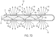
- FIG. 7D schematically depicts still another embodiment of a nasogastric system 160, which includes a tube 12 and an optical fiber 20 disposed in the tube 12.
- the tube 12 has a plurality of openings 30 formed therein.
- the openings include openings 162a, 162b, and 162c.
- the tube 12 also includes a plurality of window elements 166a, 166b, 166c.
- the optical fiber 20 has formed at a distal end 20b a plurality of light-emitting segments 3002a, 3002b, and 3002c, where the light-emitting segment 164a illuminates the windows 166a, the light-emitting segment 164b illuminates the windows 166b, and the light-emitting segment 164c illuminates the windows 166c.
- the light 106 passing through the windows can transilluminate at least a portion of the lumen and surrounding tissue of the patient so as to be monitored externally (e.g., via visualization and/or detection).
- the window elements 166a, 166b, 166c can function as color filters.
- different windows can be configured as color filters for preferentially transmitting different colors of light.
- the windows 166a can preferentially transmit blue light
- the windows 166b can preferentially transmit green light
- the windows 166c can preferentially transmit red light.
- such an embodiment can be used with a light source emitting white light such that different segments of the nasogastric tube corresponding to the different windows can be visualized (or detected) in a different color.
- FIG. 8 is a partial schematic view of a nasogastric system 170, for example, a nasogastric feeding device, which is not covered by the present invention.
- the system 170 can include a nasogastric tube 12 in which an optical fiber 20 is disposed.
- a lens 176 is attached to a distal end 12b of the tube 12 and is in optical communication with a distal end 20b of the optical fiber 20 so as to receive light therefrom.
- the lens 176 includes a substantially cylindrical shaft 176a that extends to a hemispherical tip 176b.
- the hemispherical tip 176b presents a concave surface to the incident light and hence causes divergence of the incident light 106 such that at least a portion thereof exits the tissue surrounding the feeding tube to be monitored externally (e.g., via visualization or by a detector) for guiding the nasogastric tube through the gastrointestinal tract.
- the lens 176 can be formed of a suitable polymer, such as, optical silicone rubber, PMMA (poly methyl methacrylate), polycarbonate, or glass.
- the nasogastric tube 12 further includes an opening 172.
- the opening 172 can be used to administer medicine and/or nourishment to the patient. In other embodiments, the opening 172 can allow the application of suction to a patient's stomach.
- FIG. 9 is a partial schematic view of another embodiment of a nasogastric system 180, e.g., a nasogastric feeding device, that includes a tube 12, e.g., a feeding tube
- the tube 12 includes an opening 182 disposed in a distal region thereof.
- a light source 22 e.g., an LED
- a light source 22 is disposed in the inner chamber 12d of the tube 12 in proximity to the opening 182 such that at least a portion of the light emitted by the light source passes through the opening to be monitored externally (e.g., via visualization or via a detector) for guiding the tube through the lumen, such as for example the gastrointestinal tract.
- a pair of conductors the 188a/188b can extend through the tube 12 to the light source 22 to transmit electrical power from an external source, such as an external voltage source (not shown) to the light source 22.
- the conductors 188a/188b are positioned within an electrically insulating sleeve 186.
- the light source 22 is titled toward the opening 182 so as to optimize optical coupling between the light source and the opening.
- the opening 182 can also be employed, for example, to administer medicine and/or nourishment to the patient, or apply suction to the patient's stomach, or for other purposes.
- multiple openings/windows can be employed, e.g., in a manner discussed above in connection with the previous embodiments.
- FIG. 10 schematically depicts another embodiment of a nasogastric system 190 not covered by the present invention.
- the system 190 includes a tube 12, e.g., a feeding tube, having an annular shape and a plurality of light sources 196 (e.g., a plurality of LEDs) formed in the housing of the tube (as shown), and are positioned circumferentially about the tube housing.
- the light sources can be optically coupled to the annulus portion of the feeding tube at a proximal end thereof.
- the light sources 196 can generate radiation in the visible, near-infrared or infrared portions of the electromagnetic spectrum.
- the nasogastric tube 12 is formed of a material that is substantially transparent to the radiation emitted by the light sources 196.
- the tube is formed of clear silicone rubber.
- the nasogastric device 190 can be configured as a nasogastric feeding device, in other embodiments, the nasogastric device 190 can be configured for other purposes, e.g., to compress the patient's stomach.
- At least a portion of the light emitted by the light sources 196 is transmitted along the annulus of the tube and at least a portion of the light exits the annulus at it propagates from the proximal end of the tube to its distal end. Further, a portion of the light exits the annulus at the distal end thereof. At least a portion of the light exiting the annulus can penetrate through the surrounding tissue to be monitored externally (e.g., via visualization or otherwise), e.g., in a manner discussed above.
- the light source can be a strobe light source (e.g., a strobe LED) that can provide repetitive flashes of radiation. Such flashes of radiation can be effective in capturing the attention of an operator of the device.
- a strobe light source e.g., a strobe LED
- a nasogastric device provides a number of advantages. In particular, it allows safe placement of a nasogastric tube in a patient's gastrointestinal tract without the need to expose the patient to potentially harmful radiation. This can be particularly advantageous for pediatric patients. Further, a nasogastric feeding device according to the present teachings is easy to use.
- the illumination system of the present disclosure can be used to illuminate or transilluminate other types of lumens and areas within the patient.
- the above embodiments are directed to illuminating nasal and gastric passages or lumens within the body.
- the illumination system of the present disclosure can be used to illuminate lumens in other regions of the body, including cardiac passages or lumens, including for example, venous, aortic, and capillary lumens or passages.
- the illumination system of the present disclosure can also be used to locate or visually show the location of a device inserted within a lumen in the heart region of the patient.
- FIG. 11 illustrates a lumen, such as an artery or a vein 208 that exists within the body of the patient.
- the vein 208 has an interior chamber 208a that seats a venous tube 12 suitable for use with the present disclosure.
- the tube 12 can be a catheter or the like that is sized and configured to be inserted and then eventually positioned within a cardiac region of the patient.
- the tube 12 can be inserted and positioned within the patient according to known techniques.
- the illumination system of the present disclosure includes an optical fiber 20 that is coupled to a light source 22.
- the light source 22 can be remotely positioned external of the patient or can be disposed within the patient.
- the optical fiber 20 can be positioned within the chamber 12d of the tube 12 as it is inserted within one or more lumens 208 of the body.
- the optical fiber 20 emits light that is received from the attached light source 22 so as to illuminate the area at the distal end of the tube 12, which can be formed of a substantially transparent material through which the light can exit the tube 12 and be observed externally to allow a doctor to determine the precise position of the tube as it navigates or passes through the body.
- the illumination system allows the doctor to visually determine the precise location of the tube, thus enabling the doctor to precisely locate and position the tube at a selected site within the lumen.
- other portions of the tube 12 can be substantially transparent (such as the sections discussed above in connection with the previous embodiments) to allow passage of light emitted by the optical fiber 20 therethrough.
- the optical fiber 20 can be removed from the chamber 12d of the tube 12.
- a further medical device can then be inserted into the tube so as to perform a specific function or action at the surgical site.
- the tube and illumination system can be employed during a cardiac catheterization procedure so as to assess heart function and diagnosis cardiac conditions.
- the tube or catheter 20 is inserted into a vein in the arm, neck or groin of the patient, and then the tube, with the assistance of the illumination system can be passed through the body to a selected site or location in the heart.
- the illumination system can be used to generate and emit light in the red light range so as to assist the doctor in determining the location of the catheter in the human body.
- the tube 12 and the illumination system can be used as part of an angiography or arteriography procedure.
- the tube or catheter 20 can be inserted into a lumen, such as vein or artery (e.g., femoral artery) of the patient, and the illumination system (e.g., light source 22 and optical fiber 20) helps emit light within the artery to transilluminate the artery and surrounding tissue. The light can help the doctor locate or thread the tube to the proper location within the heart. Once the tube is properly located, the optical fiber can be removed from the tube.
- a lumen such as vein or artery (e.g., femoral artery) of the patient
- the illumination system e.g., light source 22 and optical fiber 20
- the light can help the doctor locate or thread the tube to the proper location within the heart.
- the angiography procedure can be used to help visualize the inside, or lumen, of blood vessels and organs of the body, with particular interest in the arteries, veins, and the heart chambers. This is traditionally done by injecting a radio-opaque contrast agent into the blood vessel and imaging using X-ray based techniques such as fluoroscopy.
- the illumination system can be used to assist in angioplasty procedures.
- the tube or catheter 12 can be inserted within a vein and the optical fiber 20 can be inserted within the tube.
- the illumination system via the optical fiber 20 emits light at the distal end of the tube to help locate the tube within the body.
- the optical fiber can be removed from the tube.
- Angioplasty is a minimally invasive, endovascular procedure to widen narrowed or obstructed arteries or veins, typically to treat arterial atherosclerosis.
- a deflated balloon attached to a catheter e.g., a balloon catheter
- a deflated balloon attached to a catheter is passed over a guide-wire into the narrowed vessel and then inflated to a fixed size.
- the balloon forces expansion of the blood vessel and the surrounding muscular wall, allowing an improved blood flow.
- a structural support such as a stent, can then be inserted at the time of ballooning to ensure the vessel remains open, and the balloon is then deflated and withdrawn.
- FIG. 12 schematically depicts an system 500 according to an embodiment for performing angioplasty.
- the system 500 includes a tube (e.g., a catheter) 502, which extends from a proximal end to a distal end.
- a tube e.g., a catheter
- an inflatable balloon 504 is attached that can be transitioned from a deflated state into an inflated state using the techniques well known in the art.
- An optical fiber 506 is disposed within the lumen of the tube and receives light from a light source (not shown).
- At least a portion of the light received by the optical fiber exits via its distal end and passes through a transparent window 508 of the catheter and through the tissue to be observed externally so as to allow a practitioner to position the balloon in proximity of a blockage, e.g., an arterial blockage.
- a blockage e.g., an arterial blockage.
- the inflation of the balloon helps expand the atrial passage and improve the blood flow.
Landscapes
- Health & Medical Sciences (AREA)
- Life Sciences & Earth Sciences (AREA)
- Engineering & Computer Science (AREA)
- Physics & Mathematics (AREA)
- Animal Behavior & Ethology (AREA)
- General Health & Medical Sciences (AREA)
- Public Health (AREA)
- Veterinary Medicine (AREA)
- Heart & Thoracic Surgery (AREA)
- Biophysics (AREA)
- Biomedical Technology (AREA)
- Surgery (AREA)
- Pathology (AREA)
- Medical Informatics (AREA)
- Molecular Biology (AREA)
- Optics & Photonics (AREA)
- Pulmonology (AREA)
- Human Computer Interaction (AREA)
- Otolaryngology (AREA)
- Astronomy & Astrophysics (AREA)
- General Physics & Mathematics (AREA)
- General Engineering & Computer Science (AREA)
- Anesthesiology (AREA)
- Hematology (AREA)
- Nuclear Medicine, Radiotherapy & Molecular Imaging (AREA)
- Radiology & Medical Imaging (AREA)
- Medical Preparation Storing Or Oral Administration Devices (AREA)
- Endoscopes (AREA)
- Laser Surgery Devices (AREA)
Description
- The present invention relates generally to a systems and method for illuminating an interior lumen within a patient, and specifically relates to illuminated tubes that can be safely guided along a patient's lumen, such as for example a gastrointestinal tract, by monitoring light emitted from a source coupled to the tube.
- Each year, in the United States, about 1.2 million nasogastric tubes are placed in patients with a significant fraction of such tubes placed in pediatric patients. One example of a nasogastric tube is a nasogastric feeding tube that can be used to administer water, nourishment and/or medicine to a patient. For example, a so-called Dobbhoff feeding tube is a small-bore flexible tube that can be inserted through a patient's nose to the stomach, and from the stomach to the first part of the small intestine (duodenum). It can be made of a radiopaque polymeric material to allow its placement using an X-ray or fluoroscope. A nasogastric tube can also be employed for other purposes. For example, a nasogastric tube can be in the form of a large bore tube that can be used for a variety of different purposes, such as decompressing the stomach for surgery and to prevent nausea/vomiting.
- Although placement of nasogastric tubes in patients is relatively routine, there is a risk associated with each insertion. A misplaced nasogastric tube can lead to serious and even fatal complications. One conventional method for verification of the placement of a nasogastric tube is the measurement of the acidity of the gastric aspirate. Another method is the use of radiography to verify the location of the nasogastric tube. These conventional methods, however, suffer from a number of shortcomings. For example, the measurement of acidity can result in false affirmation of the placement of the nasogastric tube. Further, the radiation exposure associated with radiography is of great concern in pediatric patients.
-
US 2013/0046172 A1 discloses methods and systems for locating a feeding tube inside of a person, including a light source configured to generate light coupled to a light transmitting element.US 2008/0027408 A1 discloses a method for catheter placement, which includes inserting light from a small laser diode into a distal end of a catheter and passing the light through an optical fiber.US 2008/0039715 A1 discloses a three-dimensional optical guidance for catheter placement. This system comprises an optically-guided catheter.US 2008/0194973 A1 discloses a light-guided transluminal catheter for direct visualization of placement through the skin.JP 2015-077336 A - Accordingly, there is a need for improved nasogastric feeding devices as well as improved methods for their insertion into a patient's gastrointestinal tract.
- The above object is solved by a system according to claim 1.
- According to the present invention there is provided a system for illuminating a lumen within a body of a patient, comprising:
- a tube having a proximal end, an opposed distal end and an internal chamber, the tube being configured for placement within the lumen of the body and comprising a nasogastric feeding tube having a passageway for administration of nourishment to the patient; and
- an illumination subsystem including:
- an optical fiber that is sized and configured to seat within the internal chamber of the tube; and
- a light source for generating light that is emitted by the optical fiber, wherein a wall of the tube is substantially transparent to light emitted by the optical fiber;
- wherein the tube has multiple openings usable for administering nourishment and/or medicine to the patient, and wherein the optical fiber, when mounted within the tube and when the light source generates light, emits light at the distal end of the tube so as to transilluminate the lumen and surrounding tissue; and the optical fiber has a rounded light-emitting distal end.
- Further aspects are defined in the dependent claims.
- The present invention is directed to the ability to illuminate via light an internal or interior lumen of a patient via a fiber optic cable and an attached light source such that at least a portion of the light can be externally observed, e.g., via the naked eye or a camera. The observed light can be employed to guide a diagnostic and/or therapeutic tube (e.g., a catheter) through the lumen. The interior lumen can be any suitable lumen such as a nasogastric passage, a cardiac passage and the like.
- According to one practice, an example is directed to an illumination system for illuminating a lumen within a body of a patient, comprising a tube having a proximal end and an opposed distal end and an internal chamber, where the tube is configured for placement within a lumen of the body, and an illumination subsystem including an optical fiber that is sized and configured to seat within the internal chamber of the tube and a light source for generating light that is emitted by the fiber optic cable. The optical fiber, when mounted within the tube and when the light source generates light, emits light at the distal end of the tube so as to transilluminate the lumen and surrounding tissue so as to be able to locate (e.g., visually or with an external device such as a camera) the distal end of the tube within the lumen of the patient.
- The tube has at least one opening formed in a wall thereof, and the optical fiber has a proximal end configured for receiving light from the light source and a distal end having at least one light-emitting segment formed therein through which light from the light source exiting the optical fiber. The optical fiber is coupled to the tube such that the at least one light-emitting segment is located substantially adjacent to the at least one opening in the wall of the tube, whereby at least a portion of the light exiting the optical fiber through the at least one opening can be detected externally for guiding placement of the tube in the lumen. The light emitting segment and the opening are disposed can be disposed in registration with each other.
- According to another practice, the tube can include a plurality of openings formed in a wall thereof, where the optical fiber includes at least one light-emitting segment for emitting light received from the light source, and wherein the light-emitting segment is disposed in registration with one of the plurality of openings.
- The tube can include a plurality of openings formed in a wall thereof, and the optical fiber can include a plurality of light-emitting segments for emitting light received from the light source, wherein each of the light-emitting segments is disposed in registration with one of the plurality of openings.
- According to one embodiment, the illumination system can be configured such that the tube corresponds to a nasogastric device. The tube has a proximal end and a distal end and is configured for placement in an individual's gastrointestinal tract, where the tube has at least one opening in a wall thereof. The nasogastric device further includes at least one fiber optic (herein also referred to as an optical fiber) extending from a proximal end configured for receiving light from a light source to a distal end through which the light exits the fiber optic, the fiber optic having at least one light-emitting segment through which light exits the fiber optic, the fiber optic being coupled to said tube such that said at least one light-emitting segment of the fiber optic is located substantially adjacent to said at least one opening in the tube wall, whereby at least a portion of the light exiting the fiber optic through said at least one opening passes through said opening and propagates through tissue to be detected externally for guiding deployment and placement of the nasogastric feeding tube in the individual's gastrointestinal tract.
- In some embodiments, the nasogastric device can be a nasogastric feeding tube, which includes a passageway for administration of nourishment and/or medicine to a patient. In other embodiments, a nasogastric device according to the present teachings can be used for other purposes. For example, the nasogastric device can include a passageway to which a negative pressure can be applied for decompressing the stomach for surgery and/or to prevent nausealvomiting.
- In some embodiments, one or more light-emitting segments of the fiber optic can be positioned in a distal region of the fiber. In some such embodiments, one or more light-emitting segments of the fiber optic can be configured so as to provide side emission of the light. In some embodiments, one or more light-emitting segment(s) of the fiber optic can be configured to emit light from the distal end of the fiber optic. In some such embodiments, the light is emitted along an axial direction of the fiber optic with the divergence of the emitted light resulting in at least a portion of the light being observed externally in such a way as to allow guiding the tube along the patient's gastrointestinal tract. Further, in some embodiments in which the light is emitted from the distal end of the fiber optic, the distal region of the fiber optic is bent so as to be in substantial register with an opening in the tube, thereby enhancing the optical coupling between the light emitted by the fiber and that opening.
- In some embodiments, the tube of a nasogastric device can include a plurality of openings and the fiber optic can include a plurality of light-emitting segments. In some such embodiments, the fiber optic is disposed within the tube such that each of the plurality of light-emitting segments is in substantial register with one of the openings in the tube so as to emit light in a plurality of directions in order to facilitate the placement of the tube within a patient's gastrointestinal tract. In some embodiments, the plurality of openings are disposed in the tube so as to allow monitoring the tube regardless of its rotational orientation as it is being guided along a patient's gastrointestinal tract. By way of example, the plurality of openings can be distributed substantially uniformly around a cross-sectional circumference of the tube.
- In some embodiments, the fiber optic can be attached, e.g., glued, to an inner surface of the tube's wall. Such placement of the fiber optic can advantageously facilitate monitoring the tube via transillumination.
- The tube can be formed of a variety of different polymeric materials. In general, any suitable polymeric material can be used. Some examples of such materials include, without limitation, silicone rubber, and polyurethane.
- The nasogastric device can further include a light source that is optically coupled to the optical fiber to provide light thereto. For example, the light source can be coupled to the proximal end of the optical fiber to deliver light to the fiber. A variety of light sources can be employed in the practice of the invention. Some examples of suitable light sources include, without limitation, a light-emitting diode (LED), a laser diode, and an incandescent light source, among others. While in some embodiments, the light source can emit visible radiation, in other embodiments, the light source can emit radiation in the near-infrared region of the electromagnetic spectrum. Further, while in some embodiments, the emitted light can be white light, in other embodiments, the light source can emit substantially monochromatic light, e.g., red light. In some embodiments, the light source can emit light with wavelengths in a range of about 810 nm to about 850 nm.
- In some embodiments, the optical fiber is a single-mode fiber while in other embodiments, it can be a multi-mode fiber. The optical fiber can have, for example, a diameter in a range of about 0.5 mm to about 2 mm, though other diameters can also be used so long as the fiber can be inserted within the nasogastric tube.
- In some embodiments, an external detector can be utilized to detect externally the light emitted by the optical fiber so as to allow guiding the fiber through the patient's gastrointestinal tract. For example, in some such embodiments, a camera can be employed to the detect the light passing through the tissue. In some such embodiments, the camera can be a visible or an infrared camera.
- In a related aspect, a nasogastric device is disclosed, which includes a tube having a proximal end and a distal end and is configured for placement in an individual's gastrointestinal tract. The tube can include a tubular side wall that is configured for receiving, at its proximal end, light from a light source. The tubular side wall is substantially transparent to the received light such that the light is partially transmitted along the tubular wall and is partially transmitted to external environment via passage through an outer surface of the tubular wall to be detected externally after passage through tissue for guiding deployment and placement of the nasogastric feeding tube in the individual's gastrointestinal tract.
- In some embodiments, the nasogastric device can be a nasogastric feeding tube, which includes a passageway for administration of medicine and/or nourishment to a patient. In other embodiments, a nasogastric device according to the present teachings can be used for other purposes. For example, the nasogastric device can include a passageway to which a negative pressure can be applied for decompressing the stomach for surgery and/or to prevent nausealvomiting.
- By way of example, the tubular wall can be formed of clear silicone rubber, or any other suitable material.
- In some embodiments, a plurality of light sources are optically coupled to the proximal end of the tubular wall to deliver light from multiple points to the tubular wall so as to ensure that substantially the entire tubular wall is illuminated. This can allow for external monitoring of the tube regardless of its rotational orientation in the individual's gastrointestinal tract.
- In a related aspect, a nasogastric feeding device is disclosed, which includes a tube having a proximal end and a distal end and configured for placement in an individual's gastrointestinal tract. A light-emitting diode (LED) is coupled to the tube such that at least a portion of the light emitted by the LED passes through the opening. At least a portion of the light passing through the opening can pass through at least a portion of the surrounding tissue to be detected externally for guiding the deployment and placement of the nasogastric tube in the individual's gastrointestinal tract. For example, the LED can be positioned in the distal region of the feeding tube in proximity (and preferably in substantial register) with the opening in the distal region of the tube to allow efficient coupling of the light emitted by the LED into the tube's opening. A plurality of conductors extending through the tube can be coupled to the LED to supply electrical power thereto. In some embodiments, the conductors can be placed within an electrically insulating sleeve.
- In yet another aspect, a gastrointestinal feeding device is disclosed, which includes a feeding tube having a proximal end and a distal end. A lens is coupled to the distal end of the tube. Further, an optical fiber is positioned in the tube such that its distal end is optically coupled to the lens. A light source can be used to deliver light to a proximal end of the optical fiber. The light can be emitted by the optical fiber at its distal end to be coupled to the lens. In some embodiments, a divergent lens is employed, which can cause divergence of the light received from the optical fiber such that at least a portion of the light is transmitted through at least a portion of the surrounding tissue to be monitored externally (e.g., via visualization and/or via an external detector (such as a camera)). The lens can be formed of a variety of different materials, such as a variety of suitable polymeric materials.
- In a related aspect, a nasogastric device is disclosed, which includes a tube having a proximal end and a distal end and configured for placement in an individual's gastrointestinal tract, said tube having a window in a wall thereof, and at least one fiber optic having a proximal end configured for receiving light from a light source and a distal end, where the fiber optic has at least one light-emitting segment. The fiber optic is coupled to the tube such that said at least one light-emitting segment of the fiber optic is located substantially adjacent to said at least one window in the tube wall, whereby at least a portion of the light exiting the fiber optic through said at least one opening can be detected externally for guiding deployment and placement of the nasogastric tube in the individual's gastrointestinal tract.
- In some embodiments, the window is substantially transparent to the light emitted by the fiber optic. In some embodiments, the tube includes a plurality of windows through one or more of which the light emitted by the fiber optic transilluminate at least a portion of the tissue surrounding the tube. In some embodiments, the window can include a color filter. In some embodiments, the nasogastric device is configured for administering any of medicine and/or nourishment to a patient. In some embodiments, the nasogastric device is configured for applying suction to a patient's stomach.
- Further understanding of various aspects of the invention can be obtained by reference to the following detailed description in conjunction with the associated drawings, which are described briefly below.
- These and other features and advantages of the present invention will be more fully understood by reference to the following detailed description in conjunction with the attached drawings in which like reference numerals refer to like elements throughout the different views. The drawings illustrate principals of the disclosure and, although not to scale, show relative dimensions.
-
FIG. 1A schematically depicts an illumination system that includes a tube in the form of a gastrointestinal feeding device that is coupled to an optical fiber. -
FIG. 1B schematically depicts a light-emitting segment of the optical fiber that is positioned in proximity of at least one of the plurality of openings provided in the tube through which the light emitted by the optical fiber can pass to be externally detected. -
FIG. 1C schematically depicts that the optical fiber can be glued to the inner wall of the tube, -
FIG. 1D schematically depicts three different types of optical fibers suitable for use in various embodiments. -
FIG. 1E schematically depicts that in some embodiments the optical fiber can be disposable. -
FIG. 2A schematically depicts a portion of a handheld light source depicted inFIG. 1A , indicating the positioning of an LED in an enclosure provided in the light source's housing. -
FIG. 2B schematically depicts another view of the portion of the handheld light source depicted inFIG. 1A . -
FIG. 3 schematically depicts one example of coupling an optical fiber used in a gastrointestinal feeding device to a laser diode to receive light therefrom. -
FIG. 4 schematically depicts an optical coupling of a light-emitting segment of an optical fiber to an opening provided in a tube of a gastrointestinal feeding device. -
FIG. 5A schematically depicts a tube of a gastrointestinal feeding device in which the feeding tube has an opening at a distal end thereof and the optical fiber includes a light-emitting segment that is optically coupled to the distal opening of the feeding tube. -
FIG. 5B schematically depicts a tube of a gastrointestinal feeding device having an optical fiber with a rounded light-emitting distal end that is optically coupled to a distal opening disposed in the feeding tube. -
FIG. 6 schematically depicts a tube of a gastrointestinal feeding device according to an embodiment having an optical fiber with a bent light-emitting distal end that is optically coupled to an opening disposed in a side wall of the tube. -
FIG. 7A schematically depicts a tube according to an embodiment of the present teachings in which a fiber optic is disposed such that the light emitted from the distal end of the fiber optic passes through two of a plurality of openings provided in the tube for transillumination of at least some of the tissue surrounding the tube for facilitating the placement and guidance of the tube within a lumen of the patient. -
FIG. 7B schematically depicts a tube having a plurality of openings and an optical fiber disposed in the tube and having a plurality of light-emitting segments, each of which is in optical coupling with one of the openings disposed in the tube. -
FIG. 7C schematically depicts an embodiment of the illumination system having two windows through which the light emitted by an optical fiber disposed in the tube can exit the tube to transilluminate at least a portion of the surrounding tissue and further having a plurality of openings. -
FIG. 7D schematically depicts an embodiment of the illumination system where the tube has openings mounting a window element through which the light emitted by a fiber optic disposed in the tube can exit the tube to transilluminate at least a portion of the surrounding tissue. -
FIG. 8 schematically depicts an embodiment of the illumination where the tube includes a lens disposed at a distal end thereof for receiving light from an optical fiber positioned in the tube. -
FIG. 9 schematically depicts an embodiment of the illumination system where a light source (e.g., an LED) disposed in proximity of an opening provided in the tube to transilluminate a patient's tissue to allow safe positioning of the device in the patient's gastrointestinal tract. -
FIG. 10 schematically depicts an embodiment of the illumination where the tube is configured for receiving at a proximal end thereof light from one or more light sources. -
FIG. 11 is a schematic depiction of the illumination system where the tube is configured as a catheter for mounting within a lumen, such as a vein, of the patient during a cardiac procedure. -
FIG. 12 is a schematic depiction of the illumination system according to an embodiment for performing angioplasty. - The present invention generally relates to systems, and devices for illuminating a lumen within a human body, and can include for example a tube for positioning in a lumen within a patient, where the tube includes at least an opening and/or a window in a distal region thereof. Such a device can include an illumination system or subsystem for delivering light to the tube such that at least a portion of the delivered light exits through the opening and/or window to be detected externally (via visualization or otherwise), thereby allowing a user to guide the placement of the tube within the lumen. As used herein, the term "lumen" is intended to include any internal passage or opening within the human body, and can include nasal passages, gastric passages and chambers, intestinal tracts and openings, esophageal passages, cardiac passages, venous, capillary and aortic passages, bronchial passages, uterine tracts and openings, and the like. According to one embodiment of the present invention, the invention allows positioning a gastrointestinal tube or a cardiac tube via transillumination. In some embodiments, the illumination subsystem can include an optical fiber that is positioned within the tube to transmit light received from a remote light source to the opening (and/or window) disposed in the distal region of the tube. In other embodiments, a light source can be positioned within the tube to deliver light to the opening (and/or window). Further, in some embodiments, a lens can be coupled to the distal end of the tube to receive light from an optical fiber positioned within the tube. In some such embodiments, the lens can be a divergent lens that causes the divergence of the light incident thereon such that at least a portion of the light would exit a portion of the surrounding tissue to be detected externally. A nasogastric device according to the present teachings can be used for a variety of different purposes. For example, in some embodiments, the nasogastric device can be configured for administering medicine and/or nourishment to a patient. In other embodiments, a nasogastric device according to the present teachings can be used for decompressing the stomach for surgery and/or to prevent nausealvomiting. While in some embodiments discussed below, a nasogastric device according to the present teachings is configured as a nasogastric feeding device for administering nourishment and/or medicine to a patient, it should be understood that the teachings of the present invention are equally applicable to other types of nasogastric devices, e.g., those that are configured for decompressing a patient's stomach.
- Various terms are used herein according to the ordinary meanings, unless indicated otherwise. The terms "light" and "radiation" are used herein interchangeably to refer not only to visible radiation but also to radiation in other regions of the electromagnetic spectrum, such as near-infrared. Further, the terms "fiber optic" and "optical fiber" are used herein interchangeably to refer to a waveguide through which electromagnetic radiation can be transmitted. The term "visible light" as used herein refers to radiation wavelengths in a range of about 400 nm to about 700 nm, the term "near-infrared radiation" refers to radiation having wavelengths in a range of about 750 nm to about 2500 nm. The term "transillumination" as used herein refers to the passage of light through a body portion, e.g., to allow guiding a tube through a body lumen.
-
FIGS. 1A through 1E schematically depict an illumination system that can deliver light to a specific location or site within a lumen of the human body. According to one practice, the illumination system can be configured as a nasogastric system 10 that includes atube 12 configured for placement in a lumen of a patient, such as for example in a gastrointestinal tract for administration of enteral nutrition or compression of the stomach . Thetube 12 has aproximal end 12a and adistal end 12b. In some embodiments, thetube 12 terminates in anoutlet port 18. Aninlet port 14 is fluidly coupled to the proximal end of thetube 12 via atube section 16. Theinlet port 14 can be configured as any suitable port, such as a sump port. In some embodiments in which the nasogastric system 10 is configured for administering nourishment and/or medicine to a patient, theoutlet port 18 can be used for introducing such nourishment and/or medicine to the patient's gastrointestinal tract. In other embodiments, theoutlet port 18 can be used to connect the tube to a pump, e.g., to remove air from the patient's stomach, so as to enhance visibility of any light emitted from thetube 12. Thetube 12 can include a plurality ofopenings distal end 12b of thetube 12. As discussed in more detail below, at least one of theopenings 30 can allow for the passage of light emitted from an optical fiber incorporated into aninternal chamber 12d of the tube so as to allow tracking of thetube 12, such as for example by visualization or by detection via a detector, as the tube is being inserted and guided within a lumen, such as the gastrointestinal tract of the patient. - More specifically, the nasogastric system 10 includes an
optical fiber 20 that can be attached to aninner wall 12c of thetube 12 and can extend from theproximal end 12a of thetube 12 to thedistal end 12b. In some embodiments, theoptical fiber 20 can be attached to theinner wall 12c of the tube in a variety of different ways. By way of example, as shown schematically inFIG. 1C , theoptical fiber 20 can be glued to aninner wall 12c of thetube 12. - In other embodiments, the
optical fiber 20 can be disposed in thetube 12 such that theoptical fiber 20 can be inserted or extracted after thetube 12 is placed in the patient's gastrointestinal tract, e.g., after thedistal region 12b of thetube 12 is placed within the patient's stomach and/or duodenum. For example, theoptical fiber 20 can be inserted in thetube 12 without gluing or otherwise affixing the optical fiber to the tube. The illustratedoptical fiber 20 has aproximal end 20a and adistal end 20b. Theproximal end 20a of theoptical fiber 20 is optically coupled to alight source 22. Thelight source 22 can have any selected size, shape or configuration, and can employ any suitable type of radiation or light element for producing the light and can be coupled to any suitable type of power source. According to one embodiment, thelight source 22 can be configured as a handheld battery-operated light source that is capable of generating light. A variety of light sources emitting light in the visible and/or infrared region of the electromagnetic spectrum can be employed. In this embodiment, the handheldlight source 22 includes a light emitting diode (LED). In some embodiments, white light with wavelengths in a range of 400 to 700 nm with a minimum of about 5000 CCT (Correlated Color Temperature) to about 6200 CCT can be used. Alternatively, monochromatic light (e.g., red light) or non-visible light (e.g., with wavelengths greater than 700 nm), i.e., near-infrared (700 nm - 1400 nm) can be employed. In other embodiments, an LED emitting radiation in the infrared portion of the electromagnetic spectrum, e.g., in a wavelength range of about 600 nm to 2500 nm, can be employed. An example of such an LED is marketed by CREE under the trade designation Photo Red LED (XQEEPR). Further, the optical fiber can be composed of any suitable material, such as plastic. - With reference to
FIGS. 2A and2B , thelight source 22 includes a light element, such as theLED 24 that is disposed in anenclosure 26 provided in ahousing 28 of the light source. Alens 30 is also provided in theenclosure 26 and is optically coupled to theLED 24 to receive light therefrom. The housing also mounts a lens 31 that includes acollar 31a that can be seated on ashoulder 29 provided within theenclosure 26 to maintain the lens 31 in the enclosure and in optical coupling or communication with theLED 24. Afiber optic adapter 32 can be removably and replaceably received in the upper hollowcylindrical portion 34 of thehousing 28 to allow coupling theoptical fiber 20 to theLED 24. In this embodiment, thefiber optic adapter 32 can include a plurality ofthreads 35 that can engage with a plurality ofmating threads 37 provided on the inner wall of the upper hollowcylindrical portion 34. - The lens 31 includes a
proximal portion 40 and adistal portion 42. Theproximal portion 40 of the lens includes arecess 33 through which light from theLED 24 can enter the lens. Theproximal portion 40 includes alateral surface 40a that is configured to reflect light incident thereon via total internal reflection toward the distal portion. Some of the light entering the lens via therecess 33 passes through the proximal portion of the lens without undergoing reflections at thelateral surface 40a thereof to reach the distal portion of the lens. The light passes through the distal portion of the lens and exits anoutput surface 44 of the lens. In this embodiment, anoptical window 50 is disposed over theoutput surface 44 of the lens. Theoptical window 50 can protect the output surface of the lens and, in some embodiments, theoptical window 50 can adjust one or more characteristics of the light exiting the lens. By way of example, theoptical window 50 can be selected to function as a filter, e.g., a bandpass filter, to allow passage of certain wavelengths of light exiting the lens while blocking other wavelengths. - In some embodiments, the lens 31 can be configured to focus the light received from the
LED 24 onto an external focal point in proximity of the input surface of theoptical fiber 20 such that the divergence angle of the light propagating from the focal point to the input of the optical fiber substantially matches the numerical aperture of the optical fiber so as to allow efficient coupling of the light into the optical fiber. - In other embodiments, the
optical fiber 20 can be optically coupled to thelight source 22 using other mechanisms. For example, with reference toFIG. 3 , thelight source 22 can be alaser diode 52 having a housing 54 in which anopening 54a is formed for receiving, e.g., via a friction fit, afiber optic coupling 53 to which theoptical fiber 20 can be coupled so as to receive light from the laser diode. In some cases, a flange (not shown) can be used to ensure that the proximal end of thefiber coupling 53 is securely coupled to the opening in the housing of the light source. - With reference to
FIGS. 1A ,1B , and4 , theoptical fiber 20 is disposed in thetube 12 such that a light-emittingsegment 20c of the fiber is in substantial register with one or more of the openings 30 (e.g., opening 30a) in thedistal portion 12b of thetube 12. In other embodiments, thetube 12 can include asingle opening 30 that is configured to receive light from the optical fiber. In this embodiment, theoptical fiber 20 is a side-emitting fiber in which its light-emitting segment is angled at about 45 degrees relative to the axis of the optical fiber so as to direct the emitted light toward theopening 30a in the tube. At least a portion of the light emitted through theopening 30a passes through a portion of the surrounding tissue and can be monitored (e.g., visually and/or via an appropriate detector) to guide the nasogastric tube through the gastrointestinal tract. - The light emitted via the
optical fiber 20 that passes through surrounding tissue can be externally detected and monitored, visually or via an appropriate detector. For example, as shown schematically inFIG. 1 , acamera 60 can be employed to obtain an image of thedistal portion 12b of thetube 12 to discern the position of the tube within the gastrointestinal tract. - A variety of different fibers emitting light in a variety of different ways are disclosed. For example,
FIG. 1D shows three different types ofoptical fibers fiber 72 is covered by the present invention. Thefibers 70 and 74 are further examples not covered by the present invention. The optical fiber 70 has adistal end 70a andlight rays 70b passing through an inner chamber 70c are emitted an end region formed at thedistal end 70a. Specifically, the light is emitted at a 45-degree angle relative to a longitudinal axis of the fiber since the opening is slanted or formed at an angle. Likewise, theoptical fiber 72 has a rounded distal light-emittingend 72a, and the light rays 72b passing through aninner chamber 72c are emitted at thedistal end region 72a in a more dispersed pattern. Also, theoptical fiber 74 has a substantially flat distal light-emittingend 74a andlight rays 74b passing through an inner chamber 74c are emitted at thedistal end 70a in a relatively parallel manner. Other optical fiber configurations can also be used, such as for example fibers that have multiple light-emitting segments that are distributed along their length, where each of the light-emitting segments can be positioned in substantial registration with one of a plurality of openings disposed in the distal region of the tube, as discussed in more detail below. With reference toFIG. 1E , in some embodiments, theoptical fiber 20 can be disposable and hence can be removed, after use, from thelight source 22. The tube can be discarded as well. - Referring again to
FIG. 1A , the illumination system can be configured as a nasogastric system that employs thetube 12 and the associatedoptical fiber 20. The distal end 12B of thetube 12 can be positioned in the esophagus of the patient and can be guided to reach the patient's stomach. Theoptical fiber 20 is coupled to thelight source 22 and hence light is conveyed from thelight source 22 through the fiber to the distal end of the optical fiber and hence tube. A portion of the light emitted via the optical fiber can transilluminate at least a portion of the tissue surrounding thenasogastric tube 12, thus revealing the position of the nasogastric tube, thereby allowing a user to monitor (visually or via a detector) the tube and hence to be able to safely guide thetube 12 to the patient's stomach. - In other embodiments, the
optical fiber 20 can be configured to emit radiation axially at thedistal end 20b, or theoptical fiber 20 can include multiple light-emittingsegments 20c each of which is placed in substantial registration with one of a plurality ofopenings 30 in thetube 12 so as to emit light along a plurality of different directions for external detection. - As noted above, in some embodiments, subsequent to the placement of the
nasogastric tube 12 within a patient's gastrointestinal tract, theoptical fiber 20 used for guiding thetube 12 into position can be safely and easily removed and thetube 12 can be used for its intended purpose, e.g., to administer nourishment and/or medicine to the patient or the compress the stomach, or any other purpose. - By way of example,
FIG. 5A schematically depicts a partial view of an embodiment of anasogastric system 100 which is not part of the present invention where thetube 12 includes anopening 102a at adistal end 12b, and anoptical fiber 20 is disposed in thetube 12 so as to emit light 106 through theopening 102a. Theoptical fiber 20 includes a substantially flat light-emittingsegment 20c at thedistal end 20b, through which light is emitted from theoptical fiber 20 and which is substantially aligned with theopening 102a to allow the passage of the emitted light 106 through theopening 102a for external detection. The divergence of the light 106 exiting theopening 102a ensures that at least a portion of the light exiting theopening 102a can transilluminate at least a portion of the surrounding tissue in a manner that allows monitoring thetube 12 as it is being deployed and guided within the patient's gastrointestinal tract.FIG. 5B schematically depicts anotherembodiment 110 in which thetube 12 seats or mounts anoptical fiber 20 having adistal end 20b that has a roundedlight emitting segment 20c that is disposed within thetube 12 such that thedistal end 20b of the optical fiber is substantially aligned with theopening 102a to allow light 106 that is emitted from theopening 102a to transillumination the surrounding or adjacent tissue, thereby allowing tracking thegastrointestinal tube 12 within the patient's gastrointestinal tract. -
FIG. 6 schematically depicts another embodiment of a nasogastric system 120 which is not part of the present invention. The system includes a tube 12 (e.g., a feeding tube) in which anoptical fiber 20 is disposed. In the illustrated system 120, thetube 12 includes aside opening 30, 122 at adistal end 12b thereof and theoptical fiber 20 includes a light-emittingsegment 20c at adistal end 20b through which light 106 is emitted from the optical fiber. In this embodiment, the distal end of theoptical fiber 20b is angled or bent so as to dispose the distal light-emittingsegment 20c in substantial registration with theopening 30, 122 in the tube. - By way of further illustration,
FIG. 7A depicts yet another embodiment of anasogastric system 130 that includes atube 12, which functions as a nasogastric feeding apparatus, havingmultiple openings 30 formed therein. Theopenings 30 includeopenings optical fiber 20 that is mounted within theinternal chamber 12d of thetube 12 and has s singlelight emitting segment 20c. Theoptical fiber 20 that is disposed in thetube 12 emits light 106 at adistal end 20b such that the emitted light 106 exits thetube 12 through theopenings 132c so as to transilluminate at least a portion of the surrounding tissue and allows the nasogastric system and specifically thetube 12 to be externally monitored either visually or via a light-detecting device. In this embodiment, theother openings -
FIG. 7B depicts still anothernasogastric system 140 having atube 12, such as a feeding tube, having a plurality ofopenings 30 formed therein. The openings includeopenings optical fiber 20 includes a plurality of light-emittingsegments openings segment 144c is disposed at thedistal end 20b of the optical fiber. The light-emittingsegments segments openings 30. -
FIG. 7C schematically depicts yet still another embodiment of anasogastric system 150 according to the teachings of the present invention. The illustratedsystem 150 includes atube 12 that includes a plurality ofopenings 30 formed therein. The openings includeopenings tube 12 seats or mounts anoptical fiber 20 in thetube chamber 12d. The optical fiber has adistal end 20b that includes alight emitting segment 154. Theoptical fiber 20 is positioned within thetube 12 such that the light-emittingsegment 154 is disposed in proximity of theopenings 152c that are formed in thedistal portion 12b of thetube 12. Theopenings 152c have mounted therein awindow element 156 that can be formed of a material that is substantially transparent to the wavelength(s) of radiation emitted by the optical fiber. By way of example, thewindow element 154 can be formed of transparent silicone rubber. Further, in some embodiments, at least one of thewindows 156 can function as a color filter to preferentially allow certain radiation wavelengths to pass therethrough. For example, the window can be formed from transparent silicone rubber impregnated with appropriate dye(s) to function as a color filter. Theopenings -
FIG. 7D schematically depicts still another embodiment of anasogastric system 160, which includes atube 12 and anoptical fiber 20 disposed in thetube 12. Thetube 12 has a plurality ofopenings 30 formed therein. The openings includeopenings tube 12 also includes a plurality ofwindow elements optical fiber 20 has formed at adistal end 20b a plurality of light-emitting segments 3002a, 3002b, and 3002c, where the light-emittingsegment 164a illuminates thewindows 166a, the light-emittingsegment 164b illuminates thewindows 166b, and the light-emittingsegment 164c illuminates thewindows 166c. The light 106 passing through the windows can transilluminate at least a portion of the lumen and surrounding tissue of the patient so as to be monitored externally (e.g., via visualization and/or detection). In some embodiments, thewindow elements windows 166a can preferentially transmit blue light, thewindows 166b can preferentially transmit green light, and thewindows 166c can preferentially transmit red light. By way of example, such an embodiment can be used with a light source emitting white light such that different segments of the nasogastric tube corresponding to the different windows can be visualized (or detected) in a different color. -
FIG. 8 is a partial schematic view of anasogastric system 170, for example, a nasogastric feeding device, which is not covered by the present invention. Thesystem 170 can include anasogastric tube 12 in which anoptical fiber 20 is disposed. Alens 176 is attached to adistal end 12b of thetube 12 and is in optical communication with adistal end 20b of theoptical fiber 20 so as to receive light therefrom. Thelens 176 includes a substantiallycylindrical shaft 176a that extends to ahemispherical tip 176b. Thehemispherical tip 176b presents a concave surface to the incident light and hence causes divergence of the incident light 106 such that at least a portion thereof exits the tissue surrounding the feeding tube to be monitored externally (e.g., via visualization or by a detector) for guiding the nasogastric tube through the gastrointestinal tract. In some embodiments, thelens 176 can be formed of a suitable polymer, such as, optical silicone rubber, PMMA (poly methyl methacrylate), polycarbonate, or glass. Thenasogastric tube 12 further includes anopening 172. In some embodiments, theopening 172 can be used to administer medicine and/or nourishment to the patient. In other embodiments, theopening 172 can allow the application of suction to a patient's stomach. -
FIG. 9 is a partial schematic view of another embodiment of anasogastric system 180, e.g., a nasogastric feeding device, that includes atube 12, e.g., a feeding tube Thetube 12 includes anopening 182 disposed in a distal region thereof. In this embodiment, rather than using an optical fiber to transmit light from a light source to the distal region of the tube, alight source 22, e.g., an LED, is disposed in theinner chamber 12d of thetube 12 in proximity to theopening 182 such that at least a portion of the light emitted by the light source passes through the opening to be monitored externally (e.g., via visualization or via a detector) for guiding the tube through the lumen, such as for example the gastrointestinal tract. As shown schematically inFIG. 9 , a pair of conductors the 188a/188b can extend through thetube 12 to thelight source 22 to transmit electrical power from an external source, such as an external voltage source (not shown) to thelight source 22. In this embodiment, theconductors 188a/188b are positioned within an electricallyinsulating sleeve 186. Further, in this embodiment, thelight source 22 is titled toward theopening 182 so as to optimize optical coupling between the light source and the opening. In this embodiment, theopening 182 can also be employed, for example, to administer medicine and/or nourishment to the patient, or apply suction to the patient's stomach, or for other purposes. Further, in some implementation of thenasogastric system 180, rather than a single opening, multiple openings/windows can be employed, e.g., in a manner discussed above in connection with the previous embodiments. -
FIG. 10 schematically depicts another embodiment of anasogastric system 190 not covered by the present invention. Thesystem 190 includes atube 12, e.g., a feeding tube, having an annular shape and a plurality of light sources 196 (e.g., a plurality of LEDs) formed in the housing of the tube (as shown), and are positioned circumferentially about the tube housing. The light sources can be optically coupled to the annulus portion of the feeding tube at a proximal end thereof. Similar to the previous embodiments, thelight sources 196 can generate radiation in the visible, near-infrared or infrared portions of the electromagnetic spectrum. In this embodiment, thenasogastric tube 12 is formed of a material that is substantially transparent to the radiation emitted by thelight sources 196. By way of example, in some embodiments, the tube is formed of clear silicone rubber. While in some embodiments, thenasogastric device 190 can be configured as a nasogastric feeding device, in other embodiments, thenasogastric device 190 can be configured for other purposes, e.g., to compress the patient's stomach. - At least a portion of the light emitted by the
light sources 196 is transmitted along the annulus of the tube and at least a portion of the light exits the annulus at it propagates from the proximal end of the tube to its distal end. Further, a portion of the light exits the annulus at the distal end thereof. At least a portion of the light exiting the annulus can penetrate through the surrounding tissue to be monitored externally (e.g., via visualization or otherwise), e.g., in a manner discussed above. - As noted above, a variety of light sources can be employed in nasogastric devices according to the teachings of the present invention. By way of example, in some cases, the light source can be a strobe light source (e.g., a strobe LED) that can provide repetitive flashes of radiation. Such flashes of radiation can be effective in capturing the attention of an operator of the device.
- A nasogastric device according to the present teachings provides a number of advantages. In particular, it allows safe placement of a nasogastric tube in a patient's gastrointestinal tract without the need to expose the patient to potentially harmful radiation. This can be particularly advantageous for pediatric patients. Further, a nasogastric feeding device according to the present teachings is easy to use.
- The illumination system of the present disclosure can be used to illuminate or transilluminate other types of lumens and areas within the patient. For example, the above embodiments are directed to illuminating nasal and gastric passages or lumens within the body. Likewise, the illumination system of the present disclosure can be used to illuminate lumens in other regions of the body, including cardiac passages or lumens, including for example, venous, aortic, and capillary lumens or passages. For example, the illumination system of the present disclosure can also be used to locate or visually show the location of a device inserted within a lumen in the heart region of the patient.
FIG. 11 illustrates a lumen, such as an artery or avein 208 that exists within the body of the patient. Thevein 208 has aninterior chamber 208a that seats avenous tube 12 suitable for use with the present disclosure. Thetube 12 can be a catheter or the like that is sized and configured to be inserted and then eventually positioned within a cardiac region of the patient. Thetube 12 can be inserted and positioned within the patient according to known techniques. As shown in the previous embodiments, the illumination system of the present disclosure includes anoptical fiber 20 that is coupled to alight source 22. Thelight source 22 can be remotely positioned external of the patient or can be disposed within the patient. Theoptical fiber 20 can be positioned within thechamber 12d of thetube 12 as it is inserted within one ormore lumens 208 of the body. Theoptical fiber 20 emits light that is received from the attachedlight source 22 so as to illuminate the area at the distal end of thetube 12, which can be formed of a substantially transparent material through which the light can exit thetube 12 and be observed externally to allow a doctor to determine the precise position of the tube as it navigates or passes through the body. The illumination system allows the doctor to visually determine the precise location of the tube, thus enabling the doctor to precisely locate and position the tube at a selected site within the lumen. In other embodiments, other portions of thetube 12 can be substantially transparent (such as the sections discussed above in connection with the previous embodiments) to allow passage of light emitted by theoptical fiber 20 therethrough. - Once the
tube 12 is properly positioned within thelumen 208 of the body, theoptical fiber 20 can be removed from thechamber 12d of thetube 12. A further medical device can then be inserted into the tube so as to perform a specific function or action at the surgical site. For example, the tube and illumination system can be employed during a cardiac catheterization procedure so as to assess heart function and diagnosis cardiac conditions. During this procedure, the tube orcatheter 20 is inserted into a vein in the arm, neck or groin of the patient, and then the tube, with the assistance of the illumination system can be passed through the body to a selected site or location in the heart. The illumination system can be used to generate and emit light in the red light range so as to assist the doctor in determining the location of the catheter in the human body. - According to another practice, the
tube 12 and the illumination system can be used as part of an angiography or arteriography procedure. During the angiography procedure, the tube orcatheter 20 can be inserted into a lumen, such as vein or artery (e.g., femoral artery) of the patient, and the illumination system (e.g.,light source 22 and optical fiber 20) helps emit light within the artery to transilluminate the artery and surrounding tissue. The light can help the doctor locate or thread the tube to the proper location within the heart. Once the tube is properly located, the optical fiber can be removed from the tube. The angiography procedure can be used to help visualize the inside, or lumen, of blood vessels and organs of the body, with particular interest in the arteries, veins, and the heart chambers. This is traditionally done by injecting a radio-opaque contrast agent into the blood vessel and imaging using X-ray based techniques such as fluoroscopy. - According to still another practice, the illumination system can be used to assist in angioplasty procedures. For example, the tube or
catheter 12 can be inserted within a vein and theoptical fiber 20 can be inserted within the tube. The illumination system via theoptical fiber 20 emits light at the distal end of the tube to help locate the tube within the body. Once the tube is properly positioned, the optical fiber can be removed from the tube. Angioplasty is a minimally invasive, endovascular procedure to widen narrowed or obstructed arteries or veins, typically to treat arterial atherosclerosis. A deflated balloon attached to a catheter (e.g., a balloon catheter) is passed over a guide-wire into the narrowed vessel and then inflated to a fixed size. The balloon forces expansion of the blood vessel and the surrounding muscular wall, allowing an improved blood flow. A structural support, such as a stent, can then be inserted at the time of ballooning to ensure the vessel remains open, and the balloon is then deflated and withdrawn. - By way of further illustration,
FIG. 12 schematically depicts ansystem 500 according to an embodiment for performing angioplasty. Thesystem 500 includes a tube (e.g., a catheter) 502, which extends from a proximal end to a distal end. At the distal end of the tube, aninflatable balloon 504 is attached that can be transitioned from a deflated state into an inflated state using the techniques well known in the art. Anoptical fiber 506 is disposed within the lumen of the tube and receives light from a light source (not shown). At least a portion of the light received by the optical fiber exits via its distal end and passes through atransparent window 508 of the catheter and through the tissue to be observed externally so as to allow a practitioner to position the balloon in proximity of a blockage, e.g., an arterial blockage. As noted above, the inflation of the balloon helps expand the atrial passage and improve the blood flow.
Claims (15)
- A system (500, 10, 20, 22) for illuminating a lumen within a body of a patient, comprising:a tube (12) having a proximal end (12a), an opposed distal end (12b), and an internal chamber (12d), the tube (12) being configured for placement within the lumen of the body and comprising a nasogastric feeding tube (12) having a passageway for administration of nourishment to the patient; andan illumination subsystem including:an optical fiber (20) that is sized and configured to seat within the internal chamber (12d) of the tube (12); anda light source (22) for generating light that is emitted by the optical fiber (20),wherein a wall of the tube (12) is substantially transparent to light emitted by the optical fiber (20):wherein the tube (12) has multiple openings (30) usable for administering nourishment and/or medicine to the patient,and wherein the optical fiber 20, when mounted within the tube (12) and when the light source (22) generates light, emits light at the distal end (12d) of the tube (12) so as to transilluminate the lumen and surrounding tissue; andthe optical fiber (20) has a rounded light-emitting distal end (72a, 20c).
- The system of claim 1, wherein:
the tube (12) has an opening (102a, 152c) formed in its distal end (12b);the optical fiber (20) has a proximal end (20a) configured for receiving light from the light source (22); andthe rounded light emitting distal end (72a, 20c) of the optical fiber (20) is substantially aligned with the opening (102a, 152c) formed at the distal end of the tube (12). - The system of claim 2, wherein the optical fiber (20) is coupled to the tube (12) such that at least a portion of the light exiting the optical fiber (20) through the opening can be detected externally for guiding placement of the tube in the lumen.
- The system of claim 3, wherein the at least a portion of the light exiting the optical fiber (20) has a dispersed pattern.
- The system of claim 1, wherein the tube (12) includes a plurality of openings (162a, 162b, 162c) formed in a wall thereof, and wherein the optical fiber (20) includes at least one light-emitting segment (164a, 164b, 164c) formed for emitting light received from the light source (22), wherein the light-emitting segment is disposed in registration with one of the plurality of openings.
- The system of claim 1, wherein the tube includes a plurality of openings formed (162a, 162b, 162c) in a wall thereof, and wherein the optical fiber includes a plurality of light-emitting segments (164a, 164b, 164c) for emitting light received from the light source, wherein each of the light-emitting segments is disposed in registration with one of the plurality of openings.
- The system of claim 1, wherein the tube (12) includes at least one opening (152c) formed in a wall thereof, the system further comprising a window element (156) seated within the opening (152c).
- The system of any of the preceding claims, wherein the tube (12) is composed of any of silicone rubber, polyurethane or polyethylene.
- The system of claim 1, wherein the optical fiber (20) comprises at least one light-emitting segment (164a, 164b, 164c) positioned so as to allow for side emission of light exiting therefrom.
- The system of claim 2, wherein a distal end of the optical fiber (20b) is bent so as to direct light emitted therefrom to the at least one opening (122) in the tube.
- The system of any of the preceding claims, wherein the optical fiber (20) is attached to an inner wall (12c) of the tube (12).
- The system of any of claims 1 to 10, wherein the optical fiber (20) is removable from the internal chamber (12d) of the tube (12).
- The system of any of the preceding claims, wherein, a tip of the distal end (12b) of the tube (12) is closed.
- The system of any of the preceding claims, wherein the light source comprises a source of visible light.
- The system of claim 14, wherein the light source comprises a source of red light.
Applications Claiming Priority (2)
| Application Number | Priority Date | Filing Date | Title |
|---|---|---|---|
| US201962787688P | 2019-01-02 | 2019-01-02 | |
| PCT/US2019/069111 WO2020142518A1 (en) | 2019-01-02 | 2019-12-31 | Positioning a tube in a lumen via transillumination |
Publications (2)
| Publication Number | Publication Date |
|---|---|
| EP3905944A1 EP3905944A1 (en) | 2021-11-10 |
| EP3905944B1 true EP3905944B1 (en) | 2025-06-04 |
Family
ID=69374403
Family Applications (1)
| Application Number | Title | Priority Date | Filing Date |
|---|---|---|---|
| EP19845684.0A Active EP3905944B1 (en) | 2019-01-02 | 2019-12-31 | Positioning a tube in a lumen via transillumination |
Country Status (5)
| Country | Link |
|---|---|
| US (1) | US12023005B2 (en) |
| EP (1) | EP3905944B1 (en) |
| JP (1) | JP7633164B2 (en) |
| CA (1) | CA3125671A1 (en) |
| WO (1) | WO2020142518A1 (en) |
Families Citing this family (8)
| Publication number | Priority date | Publication date | Assignee | Title |
|---|---|---|---|---|
| US11467393B2 (en) | 2015-10-28 | 2022-10-11 | Acera, Llc | Elliptical optical lens for high output LED |
| EP3905944B1 (en) | 2019-01-02 | 2025-06-04 | Acera LLC | Positioning a tube in a lumen via transillumination |
| EP4212199B1 (en) * | 2020-09-09 | 2025-11-12 | Otsuka Clinical Solutions, Inc. | Medical tube, and medical tube position detection system |
| CN113786168A (en) * | 2021-09-10 | 2021-12-14 | 复旦大学附属中山医院 | Light source system capable of distinguishing blood vessels in adipose tissues during operation |
| JP7730503B2 (en) * | 2021-11-16 | 2025-08-28 | スタンレー電気株式会社 | Imaging device |
| CN116250940A (en) * | 2021-12-10 | 2023-06-13 | 广州迪克医疗器械有限公司 | Optical fiber mechanism for medical optical tracing and medical optical tracing system |
| WO2025205915A1 (en) * | 2024-03-29 | 2025-10-02 | 古河電気工業株式会社 | Catheter visualization device and medical catheter set |
| WO2025253906A1 (en) * | 2024-06-03 | 2025-12-11 | 株式会社ジェイ・エム・エス | Optical fiber device and distal end position detecting device for medical catheter |
Family Cites Families (116)
| Publication number | Priority date | Publication date | Assignee | Title |
|---|---|---|---|---|
| BE532581A (en) | 1954-01-29 | |||
| US3285242A (en) | 1963-07-01 | 1966-11-15 | American Cystoscope Makers Inc | Surgical headlight and light source |
| US3592199A (en) | 1970-02-09 | 1971-07-13 | Medical Products Corp | Autoclavable surgical instrument illumination |
| JPS5659005A (en) | 1979-10-22 | 1981-05-22 | Kobe Steel Ltd | Controller for hydraulic circuit including plural variable-capacity pumps in parallel |
| JPS5734823A (en) | 1980-08-07 | 1982-02-25 | Olympus Optical Co | Endoscope apparatus with adaptor |
| EP0214967A1 (en) | 1985-03-15 | 1987-03-25 | BACLIT, Paul, S. | Detachable visor |
| JPH04288960A (en) | 1991-03-08 | 1992-10-14 | Fuji Densen Denki Kk | Soldering device for electronic parts and exiting lens fitted to this soldering device |
| USD331634S (en) | 1991-04-19 | 1992-12-08 | Stewart R. Browne Mfg. Co., Inc. | Portable trouble lamp |
| US5609561A (en) | 1992-06-09 | 1997-03-11 | Olympus Optical Co., Ltd | Electronic type endoscope in which image pickup unit is dismounted to execute disinfection/sterilization processing |
| JP3148028B2 (en) | 1992-12-09 | 2001-03-19 | 新日本製鐵株式会社 | Black silicon nitride sintered body and method for producing the same |
| US5353208A (en) | 1992-12-29 | 1994-10-04 | Larry Moore | High intensity compact flashlight |
| JPH0751282A (en) | 1993-08-09 | 1995-02-28 | Olympus Optical Co Ltd | Laser medical treatment device |
| JP3050750B2 (en) | 1994-07-04 | 2000-06-12 | 旭光学工業株式会社 | Simple endoscope device |
| JPH0819507A (en) | 1994-07-07 | 1996-01-23 | Fuji Photo Optical Co Ltd | Endoscope |
| US5743848A (en) | 1995-08-31 | 1998-04-28 | Asahi Kogaku Kogyo Kabushiki Kaisha | Portable endoscope system |
| US5682199A (en) | 1996-03-28 | 1997-10-28 | Jedmed Instrument Company | Video endoscope with interchangeable endoscope heads |
| US5765223A (en) | 1996-06-04 | 1998-06-16 | Mccausland; Mary L. | Face shield |
| US6257741B1 (en) | 1997-01-03 | 2001-07-10 | Ronald R. Williams | Lamp assembly for a light source |
| JPH1176147A (en) | 1997-09-11 | 1999-03-23 | Asahi Optical Co Ltd | Simple endoscope device |
| JP2997801B2 (en) | 1997-09-18 | 2000-01-11 | オリンパス光学工業株式会社 | Endoscope device |
| DE19810184B4 (en) | 1998-03-10 | 2006-10-12 | Storz Endoskop Gmbh | Illumination system for illuminating an observation room and using the illumination system |
| US6099147A (en) | 1998-11-19 | 2000-08-08 | Streamlight, Inc. | Flashlight lamp shock absorber |
| JP2000171725A (en) | 1998-12-03 | 2000-06-23 | Olympus Optical Co Ltd | Endoscopic device |
| US6855106B2 (en) | 2000-03-16 | 2005-02-15 | Medivision, Inc. | Endoscope and camera mount |
| JP3725406B2 (en) | 2000-07-21 | 2005-12-14 | サンクス株式会社 | Optical coupling device |
| JP3828436B2 (en) | 2001-03-22 | 2006-10-04 | オリンパス株式会社 | Battery-powered endoscope device |
| WO2002103409A2 (en) * | 2001-06-19 | 2002-12-27 | The Trustees Of The University Of Pennsylvania | Optical guidance system for invasive catheter placement |
| US6584614B2 (en) | 2001-10-18 | 2003-07-01 | John J. Hogg | Face protector |
| US6866427B2 (en) | 2001-11-13 | 2005-03-15 | Lumenyte International Corporation | Fiber optic LED light |
| US6819505B1 (en) | 2003-09-08 | 2004-11-16 | William James Cassarly | Internally reflective ellipsoidal collector with projection lens |
| US20030158503A1 (en) | 2002-01-18 | 2003-08-21 | Shinya Matsumoto | Capsule endoscope and observation system that uses it |
| AUPS085002A0 (en) | 2002-03-01 | 2002-03-28 | Eveready Battery Company Inc. | A rechargeable flashlight |
| US20040049172A1 (en) | 2002-03-18 | 2004-03-11 | Root Thomas V. | Reusable instruments and related systems and methods |
| US6991603B2 (en) | 2002-05-17 | 2006-01-31 | Optim, Inc. | Insertion tube device |
| US7798692B2 (en) | 2003-03-26 | 2010-09-21 | Optim, Inc. | Illumination device |
| US20090185392A1 (en) | 2003-03-26 | 2009-07-23 | Optim, Inc. | Detachable illumination system |
| US7229201B2 (en) | 2003-03-26 | 2007-06-12 | Optim Inc. | Compact, high-efficiency, high-power solid state light source using a single solid state light-emitting device |
| US6850095B2 (en) | 2003-04-25 | 2005-02-01 | Visteon Global Technologies, Inc. | Projector optic assembly |
| US6937791B2 (en) | 2003-05-02 | 2005-08-30 | The Boeing Company | Optical coupling apparatus and method |
| US20050201100A1 (en) | 2003-09-08 | 2005-09-15 | Cassarly William J. | Led lighting assembly |
| JP4418202B2 (en) | 2003-10-06 | 2010-02-17 | オリンパス株式会社 | Endoscope |
| JPWO2006001377A1 (en) | 2004-06-28 | 2008-04-17 | オリンパス株式会社 | Endoscope device |
| AU2005267072B2 (en) | 2004-07-27 | 2010-03-11 | Biolase Technology, Inc. | Contra-angle rotating handpiece having tactile-feedback tip ferrule |
| WO2006034171A1 (en) | 2004-09-17 | 2006-03-30 | Optim, Inc. | Methods of mounting an led endoscope illuminator within an endoscope |
| US20080039715A1 (en) * | 2004-11-04 | 2008-02-14 | Wilson David F | Three-dimensional optical guidance for catheter placement |
| USD551762S1 (en) | 2005-02-23 | 2007-09-25 | Optim, Inc. | Control handle for an endoscope device |
| USD533939S1 (en) | 2005-02-23 | 2006-12-19 | Optim, Inc. | Control handle with a display for an endoscopic device |
| JP2009501551A (en) | 2005-04-01 | 2009-01-22 | ウェルチ アレン インコーポレーテッド | Colposcope instrument |
| USD561336S1 (en) | 2005-04-18 | 2008-02-05 | Optim, Inc. | Control handle for a portable endoscopic device |
| JP4448549B2 (en) | 2005-04-26 | 2010-04-14 | コダック グラフィック コミュニケーションズ カナダ カンパニー | Comparing documents with graphic elements |
| JP2007059073A (en) | 2005-08-22 | 2007-03-08 | Toshiba Lighting & Technology Corp | Lens and lighting device |
| US8954134B2 (en) * | 2005-09-13 | 2015-02-10 | Children's Medical Center Corporation | Light-guided transluminal catheter |
| JP2007091119A (en) | 2005-09-29 | 2007-04-12 | Harison Toshiba Lighting Corp | Lighting device |
| US20070104664A1 (en) | 2005-10-26 | 2007-05-10 | California Institute Of Technology | Treatment of toenail fungus |
| US7758204B2 (en) | 2006-01-26 | 2010-07-20 | Brasscorp Limited | LED spotlight |
| EP2050138A2 (en) | 2006-07-31 | 2009-04-22 | 3M Innovative Properties Company | Integrating light source module |
| AU2007283578A1 (en) | 2006-08-10 | 2008-02-14 | Upstream Engineering Oy | Illuminator method and device |
| US7976459B2 (en) | 2006-10-17 | 2011-07-12 | Intra L.L.C. | Portable endoscope for intubation |
| US9055863B2 (en) | 2006-11-14 | 2015-06-16 | Optim, Inc. | Portable endoscope |
| US7688526B2 (en) | 2007-01-18 | 2010-03-30 | Hong Kong Applied Science And Technology Research Institute Co. Ltd. | Light-emitting devices and lens therefor |
| US20130046172A1 (en) | 2007-03-14 | 2013-02-21 | Kathryn A. McKenzie Waitzman | Methods and systems for locating a feeding tube inside of a person |
| US7976537B2 (en) | 2007-06-28 | 2011-07-12 | Biosense Webster, Inc. | Optical pyrometric catheter for tissue temperature monitoring during cardiac ablation |
| USD581052S1 (en) | 2007-09-14 | 2008-11-18 | Optim, Incorporated | Control handle for an endoscopic device |
| US8152715B2 (en) | 2007-09-14 | 2012-04-10 | Optim, Incorporated | Endoscope with internal light source and power supply |
| USD631567S1 (en) | 2008-01-11 | 2011-01-25 | Pervaiz Lodhie | LED bulb |
| US8657812B2 (en) | 2008-05-19 | 2014-02-25 | Boston Scientific Scimed, Inc. | Side-firing laser fiber with internal bent fiber and related methods |
| US8534890B2 (en) | 2008-10-09 | 2013-09-17 | Tyco Electronics Canada Ulc | Light pipe assembly having optical concentrator |
| CN102395911B (en) | 2009-02-03 | 2015-07-15 | 福雷恩公司 | Light Mixing Lenses and Systems |
| US20100277894A1 (en) | 2009-05-01 | 2010-11-04 | Kim Paul Y | Lighting device with removable cradle |
| USD623786S1 (en) | 2009-12-24 | 2010-09-14 | Wessel Elmer A | Convertible work light |
| TWD139381S1 (en) | 2010-02-05 | 2011-03-01 | 億光電子工業股份有限公司 | Led lamp |
| WO2011100432A2 (en) | 2010-02-10 | 2011-08-18 | Fraen Corporation | Light repositioning optics |
| USD663445S1 (en) | 2010-02-23 | 2012-07-10 | S. K. G. Co., Ltd. | LED light bulb |
| USD671241S1 (en) | 2010-02-23 | 2012-11-20 | S. K. G. Co., Ltd. | LED light bulb |
| TWD142719S1 (en) | 2010-04-23 | 2011-09-11 | Skg股份有限公司 | Light emitting diode light bulb |
| USD666340S1 (en) | 2010-04-23 | 2012-08-28 | S. K. G. Co., Ltd. | LED light bulb |
| CN201680208U (en) | 2010-05-27 | 2010-12-22 | 中国科学院西安光学精密机械研究所 | Lighting system applied in liquid oxygen environment |
| GB201012764D0 (en) | 2010-07-30 | 2010-09-15 | Element Six N V | A diamond window component for a laser tool |
| JP6014311B2 (en) | 2011-07-19 | 2016-10-25 | 岩崎電気株式会社 | lamp |
| USD675349S1 (en) | 2011-01-10 | 2013-01-29 | Rambus International Ltd. | Light conductor and light emitter for a LED light source |
| US9011383B2 (en) | 2011-01-14 | 2015-04-21 | Loma Linda University | Self-illuminating endogastric tubes and method of placing endogastric tubes |
| USD663464S1 (en) | 2011-01-26 | 2012-07-10 | Edison Opto Corporation | LED lamp |
| USD685506S1 (en) | 2011-07-26 | 2013-07-02 | Cree, Inc. | Lamp |
| JP2013123477A (en) | 2011-12-13 | 2013-06-24 | Olympus Corp | Radiation module having plurality of light guide members |
| USD669200S1 (en) | 2011-12-26 | 2012-10-16 | Power Digital Delight Co., Ltd. | LED light bulb |
| JP2013198644A (en) | 2012-03-26 | 2013-10-03 | Panasonic Corp | Tube distal end position confirmation device |
| USD752777S1 (en) | 2014-06-02 | 2016-03-29 | Soraa, Inc. | LED lamp |
| USD739586S1 (en) | 2012-08-15 | 2015-09-22 | Heshan Gmy Lighting And Electrical Co., Ltd. | Ultraviolet light sterilizer |
| USD775752S1 (en) | 2012-12-07 | 2017-01-03 | The Noco Company | Rechargeable device with flashlight and electronic device charger |
| USD690383S1 (en) | 2013-02-25 | 2013-09-24 | Yasar Sheikh | Combination stun gun and flashlight with a cap |
| US9364167B2 (en) * | 2013-03-15 | 2016-06-14 | Lx Medical Corporation | Tissue imaging and image guidance in luminal anatomic structures and body cavities |
| USD715463S1 (en) | 2013-06-04 | 2014-10-14 | Component Hardware Group, Inc. | LED bulb |
| USD778473S1 (en) | 2013-08-27 | 2017-02-07 | Wilmar Corporation | Light tool |
| CN105814473B (en) | 2013-09-12 | 2019-01-11 | 夸克星有限责任公司 | Light emitting device with total internal reflection (TIR) extractor |
| JP2015056137A (en) | 2013-09-13 | 2015-03-23 | 株式会社リコー | System and information processing method |
| JP6375108B2 (en) | 2013-10-18 | 2018-08-15 | ジーニアルライト株式会社 | Biological monitoring device |
| WO2015116926A1 (en) | 2014-01-31 | 2015-08-06 | Eveready Battery Company, Inc. | Collimating lens with convex hyperbolic surface |
| USD744674S1 (en) | 2014-03-13 | 2015-12-01 | Lumenmax Optoelectronics Co., Ltd. | Fluorescent lamp |
| US9894952B2 (en) | 2014-08-25 | 2018-02-20 | Arthur Hayes | Face shield attachment assembly |
| US10166307B2 (en) | 2014-10-28 | 2019-01-01 | Sensor Electronic Technology, Inc. | Adhesive device with ultraviolet element |
| JP2016087091A (en) | 2014-11-05 | 2016-05-23 | ウシオ電機株式会社 | Catheter device and catheter position confirmation method |
| USD753322S1 (en) | 2015-02-27 | 2016-04-05 | Tadd, LLC | LED lamp |
| USD760928S1 (en) | 2015-03-27 | 2016-07-05 | Yuyao Yuchang Electrical Appliance Co., Ltd. | Working lamp |
| USD768321S1 (en) | 2015-07-08 | 2016-10-04 | Mathew Inskeep | Work light |
| CN205079073U (en) | 2015-09-11 | 2016-03-09 | 陈贵生 | Through rotatory LED highlight flashlight of adjusting luminance |
| USD836227S1 (en) | 2015-10-28 | 2018-12-18 | Acera, Llc | Handheld mobile light source |
| US11467393B2 (en) | 2015-10-28 | 2022-10-11 | Acera, Llc | Elliptical optical lens for high output LED |
| USD793595S1 (en) | 2016-01-05 | 2017-08-01 | Nite Ize, Inc. | Glowstick |
| US10835718B2 (en) * | 2016-03-28 | 2020-11-17 | Becton, Dickinson And Company | Cannula with light-emitting optical fiber |
| USD804064S1 (en) | 2016-09-27 | 2017-11-28 | Tadd, LLC | LED bulb |
| USD810325S1 (en) | 2017-01-16 | 2018-02-13 | Shenzhen Snc Opto Electronic Co., Ltd. | Dustproof corn light |
| WO2018207753A1 (en) | 2017-05-11 | 2018-11-15 | アルプス電気株式会社 | Catheter device, connector device, and catheter system |
| KR102667722B1 (en) | 2017-12-06 | 2024-05-22 | 서울바이오시스 주식회사 | Light irradiation device |
| EP3905944B1 (en) | 2019-01-02 | 2025-06-04 | Acera LLC | Positioning a tube in a lumen via transillumination |
| US20210299298A1 (en) | 2020-03-25 | 2021-09-30 | Acera LLC | Portable sterilization device |
| WO2021202641A1 (en) | 2020-04-02 | 2021-10-07 | Acera LLC | A headgear shield |
-
2019
- 2019-12-31 EP EP19845684.0A patent/EP3905944B1/en active Active
- 2019-12-31 US US16/731,852 patent/US12023005B2/en active Active
- 2019-12-31 JP JP2021538760A patent/JP7633164B2/en active Active
- 2019-12-31 WO PCT/US2019/069111 patent/WO2020142518A1/en not_active Ceased
- 2019-12-31 CA CA3125671A patent/CA3125671A1/en active Pending
Also Published As
| Publication number | Publication date |
|---|---|
| US20200205640A1 (en) | 2020-07-02 |
| EP3905944A1 (en) | 2021-11-10 |
| JP7633164B2 (en) | 2025-02-19 |
| CA3125671A1 (en) | 2020-07-09 |
| US12023005B2 (en) | 2024-07-02 |
| WO2020142518A1 (en) | 2020-07-09 |
| JP2022516171A (en) | 2022-02-24 |
Similar Documents
| Publication | Publication Date | Title |
|---|---|---|
| EP3905944B1 (en) | Positioning a tube in a lumen via transillumination | |
| JP4842509B2 (en) | Optical guidance system for placement of invasive catheters | |
| US8078261B2 (en) | Light-guided transluminal catheter | |
| US8954134B2 (en) | Light-guided transluminal catheter | |
| EP2739208B1 (en) | A system for locating a catheter in a vessel | |
| US20080132990A1 (en) | Stent delivery system with imaging capability | |
| US20130211246A1 (en) | METHODS AND DEVICES FOR GASTROINTESTINAL SURGICAL PROCEDURES USING NEAR INFRARED (nIR) IMAGING TECHNIQUES | |
| JPH0444537B2 (en) | ||
| CN103249359A (en) | Medical tool that emits near infrared fluorescence and medical tool position-confirming system | |
| JP2012504019A (en) | Systems and methods for optical viewing and therapeutic intervention in blood vessels | |
| KR20110066137A (en) | Endoscopy systems, how to use them, aids, and adapters | |
| KR20140001870A (en) | Sinus illumination lightwire device | |
| ES2939538T3 (en) | Light-emitting fiber optic cannula | |
| CN109069222B (en) | cannula positioning device | |
| US20170143200A1 (en) | Laparoscopic device and endoscopic system | |
| US9810836B2 (en) | External tube, laser transmission path, and laser treatment tool | |
| CN101128151A (en) | Optical guidance system for precise placement of medical catheters in patients | |
| JP4886698B2 (en) | Optically guided system for precise patient placement of medical catheters | |
| KR20180074858A (en) | Disposable Separate Endoscope Including Plastic Optical Fiber | |
| JP3506999B2 (en) | Endoscope device | |
| CN120456951A (en) | Vascular puncture equipment and vascular puncture system |
Legal Events
| Date | Code | Title | Description |
|---|---|---|---|
| STAA | Information on the status of an ep patent application or granted ep patent |
Free format text: STATUS: UNKNOWN |
|
| STAA | Information on the status of an ep patent application or granted ep patent |
Free format text: STATUS: THE INTERNATIONAL PUBLICATION HAS BEEN MADE |
|
| PUAI | Public reference made under article 153(3) epc to a published international application that has entered the european phase |
Free format text: ORIGINAL CODE: 0009012 |
|
| STAA | Information on the status of an ep patent application or granted ep patent |
Free format text: STATUS: REQUEST FOR EXAMINATION WAS MADE |
|
| 17P | Request for examination filed |
Effective date: 20210729 |
|
| AK | Designated contracting states |
Kind code of ref document: A1 Designated state(s): AL AT BE BG CH CY CZ DE DK EE ES FI FR GB GR HR HU IE IS IT LI LT LU LV MC MK MT NL NO PL PT RO RS SE SI SK SM TR |
|
| DAV | Request for validation of the european patent (deleted) | ||
| DAX | Request for extension of the european patent (deleted) | ||
| STAA | Information on the status of an ep patent application or granted ep patent |
Free format text: STATUS: EXAMINATION IS IN PROGRESS |
|
| 17Q | First examination report despatched |
Effective date: 20231220 |
|
| GRAP | Despatch of communication of intention to grant a patent |
Free format text: ORIGINAL CODE: EPIDOSNIGR1 |
|
| STAA | Information on the status of an ep patent application or granted ep patent |
Free format text: STATUS: GRANT OF PATENT IS INTENDED |
|
| INTG | Intention to grant announced |
Effective date: 20250124 |
|
| RIN1 | Information on inventor provided before grant (corrected) |
Inventor name: JONES, CARLTON Inventor name: COOK, MICHAEL Inventor name: EPSTEIN, MICHAEL S. Inventor name: ROOT, THOMAS V. Inventor name: MIIKE, SHINYA |
|
| GRAS | Grant fee paid |
Free format text: ORIGINAL CODE: EPIDOSNIGR3 |
|
| GRAA | (expected) grant |
Free format text: ORIGINAL CODE: 0009210 |
|
| STAA | Information on the status of an ep patent application or granted ep patent |
Free format text: STATUS: THE PATENT HAS BEEN GRANTED |
|
| AK | Designated contracting states |
Kind code of ref document: B1 Designated state(s): AL AT BE BG CH CY CZ DE DK EE ES FI FR GB GR HR HU IE IS IT LI LT LU LV MC MK MT NL NO PL PT RO RS SE SI SK SM TR |
|
| REG | Reference to a national code |
Ref country code: GB Ref legal event code: FG4D |
|
| REG | Reference to a national code |
Ref country code: CH Ref legal event code: EP |
|
| REG | Reference to a national code |
Ref country code: DE Ref legal event code: R096 Ref document number: 602019070858 Country of ref document: DE |
|
| REG | Reference to a national code |
Ref country code: IE Ref legal event code: FG4D |
|
| REG | Reference to a national code |
Ref country code: NL Ref legal event code: MP Effective date: 20250604 |
|
| PG25 | Lapsed in a contracting state [announced via postgrant information from national office to epo] |
Ref country code: ES Free format text: LAPSE BECAUSE OF FAILURE TO SUBMIT A TRANSLATION OF THE DESCRIPTION OR TO PAY THE FEE WITHIN THE PRESCRIBED TIME-LIMIT Effective date: 20250604 Ref country code: FI Free format text: LAPSE BECAUSE OF FAILURE TO SUBMIT A TRANSLATION OF THE DESCRIPTION OR TO PAY THE FEE WITHIN THE PRESCRIBED TIME-LIMIT Effective date: 20250604 |
|
| REG | Reference to a national code |
Ref country code: LT Ref legal event code: MG9D |
|
| PG25 | Lapsed in a contracting state [announced via postgrant information from national office to epo] |
Ref country code: GR Free format text: LAPSE BECAUSE OF FAILURE TO SUBMIT A TRANSLATION OF THE DESCRIPTION OR TO PAY THE FEE WITHIN THE PRESCRIBED TIME-LIMIT Effective date: 20250905 Ref country code: NO Free format text: LAPSE BECAUSE OF FAILURE TO SUBMIT A TRANSLATION OF THE DESCRIPTION OR TO PAY THE FEE WITHIN THE PRESCRIBED TIME-LIMIT Effective date: 20250904 |
|
| PG25 | Lapsed in a contracting state [announced via postgrant information from national office to epo] |
Ref country code: PL Free format text: LAPSE BECAUSE OF FAILURE TO SUBMIT A TRANSLATION OF THE DESCRIPTION OR TO PAY THE FEE WITHIN THE PRESCRIBED TIME-LIMIT Effective date: 20250604 |
|
| PG25 | Lapsed in a contracting state [announced via postgrant information from national office to epo] |
Ref country code: BG Free format text: LAPSE BECAUSE OF FAILURE TO SUBMIT A TRANSLATION OF THE DESCRIPTION OR TO PAY THE FEE WITHIN THE PRESCRIBED TIME-LIMIT Effective date: 20250604 |
|
| PG25 | Lapsed in a contracting state [announced via postgrant information from national office to epo] |
Ref country code: HR Free format text: LAPSE BECAUSE OF FAILURE TO SUBMIT A TRANSLATION OF THE DESCRIPTION OR TO PAY THE FEE WITHIN THE PRESCRIBED TIME-LIMIT Effective date: 20250604 |
|
| PG25 | Lapsed in a contracting state [announced via postgrant information from national office to epo] |
Ref country code: RS Free format text: LAPSE BECAUSE OF FAILURE TO SUBMIT A TRANSLATION OF THE DESCRIPTION OR TO PAY THE FEE WITHIN THE PRESCRIBED TIME-LIMIT Effective date: 20250904 |
|
| PG25 | Lapsed in a contracting state [announced via postgrant information from national office to epo] |
Ref country code: LV Free format text: LAPSE BECAUSE OF FAILURE TO SUBMIT A TRANSLATION OF THE DESCRIPTION OR TO PAY THE FEE WITHIN THE PRESCRIBED TIME-LIMIT Effective date: 20250604 |
|
| PG25 | Lapsed in a contracting state [announced via postgrant information from national office to epo] |
Ref country code: NL Free format text: LAPSE BECAUSE OF FAILURE TO SUBMIT A TRANSLATION OF THE DESCRIPTION OR TO PAY THE FEE WITHIN THE PRESCRIBED TIME-LIMIT Effective date: 20250604 |
|
| PG25 | Lapsed in a contracting state [announced via postgrant information from national office to epo] |
Ref country code: PT Free format text: LAPSE BECAUSE OF FAILURE TO SUBMIT A TRANSLATION OF THE DESCRIPTION OR TO PAY THE FEE WITHIN THE PRESCRIBED TIME-LIMIT Effective date: 20251006 |
|
| REG | Reference to a national code |
Ref country code: AT Ref legal event code: MK05 Ref document number: 1799530 Country of ref document: AT Kind code of ref document: T Effective date: 20250604 |
|
| PG25 | Lapsed in a contracting state [announced via postgrant information from national office to epo] |
Ref country code: IS Free format text: LAPSE BECAUSE OF FAILURE TO SUBMIT A TRANSLATION OF THE DESCRIPTION OR TO PAY THE FEE WITHIN THE PRESCRIBED TIME-LIMIT Effective date: 20251004 |
|
| PGFP | Annual fee paid to national office [announced via postgrant information from national office to epo] |
Ref country code: GB Payment date: 20251229 Year of fee payment: 7 |
|
| PG25 | Lapsed in a contracting state [announced via postgrant information from national office to epo] |
Ref country code: SM Free format text: LAPSE BECAUSE OF FAILURE TO SUBMIT A TRANSLATION OF THE DESCRIPTION OR TO PAY THE FEE WITHIN THE PRESCRIBED TIME-LIMIT Effective date: 20250604 Ref country code: AT Free format text: LAPSE BECAUSE OF FAILURE TO SUBMIT A TRANSLATION OF THE DESCRIPTION OR TO PAY THE FEE WITHIN THE PRESCRIBED TIME-LIMIT Effective date: 20250604 |
|
| PGFP | Annual fee paid to national office [announced via postgrant information from national office to epo] |
Ref country code: FR Payment date: 20251226 Year of fee payment: 7 |
|
| PG25 | Lapsed in a contracting state [announced via postgrant information from national office to epo] |
Ref country code: CZ Free format text: LAPSE BECAUSE OF FAILURE TO SUBMIT A TRANSLATION OF THE DESCRIPTION OR TO PAY THE FEE WITHIN THE PRESCRIBED TIME-LIMIT Effective date: 20250604 |
|
| PG25 | Lapsed in a contracting state [announced via postgrant information from national office to epo] |
Ref country code: EE Free format text: LAPSE BECAUSE OF FAILURE TO SUBMIT A TRANSLATION OF THE DESCRIPTION OR TO PAY THE FEE WITHIN THE PRESCRIBED TIME-LIMIT Effective date: 20250604 |
|
| PG25 | Lapsed in a contracting state [announced via postgrant information from national office to epo] |
Ref country code: SK Free format text: LAPSE BECAUSE OF FAILURE TO SUBMIT A TRANSLATION OF THE DESCRIPTION OR TO PAY THE FEE WITHIN THE PRESCRIBED TIME-LIMIT Effective date: 20250604 Ref country code: RO Free format text: LAPSE BECAUSE OF FAILURE TO SUBMIT A TRANSLATION OF THE DESCRIPTION OR TO PAY THE FEE WITHIN THE PRESCRIBED TIME-LIMIT Effective date: 20250604 |
|
| PG25 | Lapsed in a contracting state [announced via postgrant information from national office to epo] |
Ref country code: IT Free format text: LAPSE BECAUSE OF FAILURE TO SUBMIT A TRANSLATION OF THE DESCRIPTION OR TO PAY THE FEE WITHIN THE PRESCRIBED TIME-LIMIT Effective date: 20250604 |
|
| REG | Reference to a national code |
Ref country code: DE Ref legal event code: R081 Ref document number: 602019070858 Country of ref document: DE Owner name: ACERA LLC, BEVERLY, US Free format text: FORMER OWNERS: ACERA LLC, BEVERLY, MA, US; FRAEN CORPORATION, READING, MA, US; NEUROCEUTICALS INC., TOKYO, JP Ref country code: DE Ref legal event code: R081 Ref document number: 602019070858 Country of ref document: DE Owner name: FRAEN CORPORATION, READING, US Free format text: FORMER OWNERS: ACERA LLC, BEVERLY, MA, US; FRAEN CORPORATION, READING, MA, US; NEUROCEUTICALS INC., TOKYO, JP Ref country code: DE Ref legal event code: R081 Ref document number: 602019070858 Country of ref document: DE Owner name: OTSUKA CLINICAL SOLUTIONS, INC., URUMA, JP Free format text: FORMER OWNERS: ACERA LLC, BEVERLY, MA, US; FRAEN CORPORATION, READING, MA, US; NEUROCEUTICALS INC., TOKYO, JP |