EP3878251B1 - A control module, and a control arrangement for a milking plant - Google Patents
A control module, and a control arrangement for a milking plant Download PDFInfo
- Publication number
- EP3878251B1 EP3878251B1 EP19805420.7A EP19805420A EP3878251B1 EP 3878251 B1 EP3878251 B1 EP 3878251B1 EP 19805420 A EP19805420 A EP 19805420A EP 3878251 B1 EP3878251 B1 EP 3878251B1
- Authority
- EP
- European Patent Office
- Prior art keywords
- control module
- front plate
- milking
- casing
- control
- Prior art date
- Legal status (The legal status is an assumption and is not a legal conclusion. Google has not performed a legal analysis and makes no representation as to the accuracy of the status listed.)
- Active
Links
Images


Classifications
-
- H—ELECTRICITY
- H05—ELECTRIC TECHNIQUES NOT OTHERWISE PROVIDED FOR
- H05K—PRINTED CIRCUITS; CASINGS OR CONSTRUCTIONAL DETAILS OF ELECTRIC APPARATUS; MANUFACTURE OF ASSEMBLAGES OF ELECTRICAL COMPONENTS
- H05K5/00—Casings, cabinets or drawers for electric apparatus
- H05K5/06—Hermetically-sealed casings
- H05K5/069—Other details of the casing, e.g. wall structure, passage for a connector, a cable, a shaft
-
- A—HUMAN NECESSITIES
- A01—AGRICULTURE; FORESTRY; ANIMAL HUSBANDRY; HUNTING; TRAPPING; FISHING
- A01J—MANUFACTURE OF DAIRY PRODUCTS
- A01J5/00—Milking machines or devices
- A01J5/007—Monitoring milking processes; Control or regulation of milking machines
-
- H—ELECTRICITY
- H05—ELECTRIC TECHNIQUES NOT OTHERWISE PROVIDED FOR
- H05K—PRINTED CIRCUITS; CASINGS OR CONSTRUCTIONAL DETAILS OF ELECTRIC APPARATUS; MANUFACTURE OF ASSEMBLAGES OF ELECTRICAL COMPONENTS
- H05K5/00—Casings, cabinets or drawers for electric apparatus
- H05K5/0026—Casings, cabinets or drawers for electric apparatus provided with connectors and printed circuit boards [PCB], e.g. automotive electronic control units
-
- H—ELECTRICITY
- H05—ELECTRIC TECHNIQUES NOT OTHERWISE PROVIDED FOR
- H05K—PRINTED CIRCUITS; CASINGS OR CONSTRUCTIONAL DETAILS OF ELECTRIC APPARATUS; MANUFACTURE OF ASSEMBLAGES OF ELECTRICAL COMPONENTS
- H05K5/00—Casings, cabinets or drawers for electric apparatus
- H05K5/02—Details
- H05K5/0247—Electrical details of casings, e.g. terminals, passages for cables or wiring
-
- H—ELECTRICITY
- H05—ELECTRIC TECHNIQUES NOT OTHERWISE PROVIDED FOR
- H05K—PRINTED CIRCUITS; CASINGS OR CONSTRUCTIONAL DETAILS OF ELECTRIC APPARATUS; MANUFACTURE OF ASSEMBLAGES OF ELECTRICAL COMPONENTS
- H05K5/00—Casings, cabinets or drawers for electric apparatus
- H05K5/06—Hermetically-sealed casings
- H05K5/064—Hermetically-sealed casings sealed by potting, e.g. waterproof resin poured in a rigid casing
Definitions
- the present invention refers generally to a control module for a milking position and to a control arrangement for a milking plant. More specifically, and according to the preamble of claim 1, the present invention refers to a control module for controlling and supervising various functions of a milking position for milking a respective dairy animal.
- the present invention also refers to a control arrangement forming an overall control system for controlling and supervising various functions of a milking plant incorporating a plurality of milking positions for milking a respective dairy animal.
- known control arrangements for milking plants require fairly extensive installation work in order to be properly adapted to the specific requirements of the milking plant and to various preferences of the individual farmer.
- the known control arrangements are not always well adapted to milking plants of different sizes and kinds, and not to the various functions to be controlled and supervised at each milking position of a milking plant.
- known control arrangements may not in an easy manner permit addition of further control and supervising functions once they have been installed, or conversely, they may contain more control and supervising functions than demanded by the farmer.
- Another problem of the known control arrangements is related to the fact that the milking plants constitute a very difficult environment for electronic control equipment. Humidity and various harmful substances may circulate in the air in the milking plant and may deteriorate the reliability and the functioning of the electronic equipment of the control arrangement.
- Another problem of the known control arrangements is that it is difficult to locate them in an ergonomic position for the staff performing the milking.
- a position which is suitable for e.g. pushing buttons is not necessarily suitable for e.g. viewing and reading instructions/feedback, and vice versa.
- WO 2008/051134 discloses an arrangement provided in a milking system for simultaneous milking of a plurality of animals, wherein the milking system comprises a plurality of milking positions and an arrangement for establishing identities of and expected milking times for the animals.
- Each of the milking positions is provided with teatcups, which are attached to the teats of an animal and are connected to a source of vacuum for milking the animal.
- the arrangement comprises means for determining a milking position, at which the animal having the longest expected milking time is present, based on the established identities and expected milking times, and a device for performing an action with respect to the milking system in response to the determination.
- WO 2006/068589 refers to a compact modular unit to be mounted in a milking stall comprising at least one pipeline system, which provides an operative function in connection with a milking process of an animal in the milking stall.
- the compact modular unit comprises a casing, which defines an inner space of the compact modular unit, an electric control unit, which is mounted in said inner space of the compact modular unit, and indication means, which are arranged to display information related to the milking processes in the milking stall.
- the compact modular unit comprises a component of the pipeline system, which is mounted in the inner space of the compact modular unit.
- a further publication CN 205 644 162 U discloses a universal intelligent milking controller comprising a casing and communication module.
- the purpose of the present invention is to provide a solution to the problems discussed above, and more precisely to provide improved means for controlling and supervising a milking position of a milking plant, and for controlling and supervising a milking plant comprising a plurality of milking position.
- control module initially defined, which is characterized in that the casing comprises an inner front plate, that the front side of the printed circuit is attached to a rear side of the inner front plate by means of a transparent adhering substance, for instance a transparent glue, so that at least a the part of the printed circuit board projects from the rear side of the inner front plate, that the inner front casing plate permits access to the communication area through the inner front plate, and that said part of the printed circuit board is embedded in a block of plastic material.
- a transparent adhering substance for instance a transparent glue
- the resistance to humidity and harmful substances of the environment may be enhanced.
- the control module may withstand the washing procedure of the milking position when water, or any other washing liquid, is sprayed onto the equipment, including the control module, frequently under high pressure.
- the block of plastic material provides a good protection to the printed circuit board inside the casing, even if humidity and any harmful substance would reach the inner space of the casing.
- the plastic material may comprise or consist of polyurethane.
- the functions comprise at least one of the following functions: milk meter supervision, pulsator rate control and supervision, vacuum shut-off of milking vacuum, retraction of milking cluster, spraying disinfectant, initiating start of milking operation, opening and closing of gates, etc.
- the casing comprises an outer rear casing that together with the inner front plate encloses the inner space.
- the outer rear casing and the inner front plate are assembled along a respective edge to form the inner space.
- a gasket may be provided between the edges of the outer rear casing and the inner front plate.
- the input and output connections extend from the printed circuit board, or from the rear side of the printed circuit board, through and beyond the block of plastic material.
- the input and output connections may be enclosed in the casing.
- the communication area comprises a contact surface and a light emitting surface, wherein light emitted by the light emitting surface is visible from outside the casing.
- the communication area is accessible through the inner front plate and the transparent adhering substance.
- the light emitting surface emits different light signals for indicating various states of some of the functions. These states may include, for instance, a full milk flow, washing is ongoing, a waiting state, a standby state, an alarm etc.
- the different light signals may include light of different colors, flashing light, circulating light, light moving back and forth etc.
- the control module comprises at least one button, which is accessible from outside the casing and acts on the contact surface for initiating and/or interrupting one of the functions via the electric lines. For instance, by activating the button, start of the milking operation may be initiated, or the milking vacuum may be shut-off and retraction of the milking cluster initiated.
- buttons accessible from outside the casing and acting on the contact surface, may be provided for selecting the function to be initiated and/or interrupted by said button.
- control module comprises a display, which is visible from outside the casing and is connected to the contact surface of the communication area for displaying a state of some of the functions.
- the inner front plate comprises at least one light guide, which is transparent to the light emitted by the light emitting surface and provided opposite to the light emitting surface.
- the inner front plate comprises an aperture giving access to the contact surface.
- the light guide surrounds the aperture.
- the light guide may thus surround the button, so that a ring of different light signals may be formed around the button.
- the block of plastic material is enclosed in an inner casing formed by an inner rear casing and the inner front plate, wherein the inner rear casing is enclosed in the casing.
- an inner casing further improves the protection against the environment of the milking plant, and during the above-mentioned washing procedure.
- the casing may comprise one or more venting holes to permit gases and liquids to escape from the inner space between the inner casing and the casing. This is advantageous, especially during the above-mentioned washing procedure.
- an outer front plate is attached to the inner front plate and comprises an opening providing access to the communication area.
- the button extends through the opening, and wherein the outer front plate comprises a light zone that surrounds the opening, is transparent to the light emitted by the light emitting surface, and is provided opposite to the light emitting surface.
- the electric lines are grouped in at least two cables, for instance two, three, four, five, six, etc. cables.
- Such preprepared cables are easy to install and may contribute to a more efficient installation of the control arrangement.
- Each cable may comprise an insulation, or a tight insulation, enclosing the respective electric lines, especially a large number of electric lines running within the insulation of each cable.
- the control module is adapted to receive a plurality of cables, each comprising a plurality of electric lines, to which the module is connectable.
- a cable clamp is provided in the casing and comprises a first clamp part and a second clamp part, wherein the first and second clamp parts form a respective cable channel for each of said at least two cables.
- the cable clamp is provided between the inner rear casing and the inner front plate.
- the cable clamp my thus be located at least partly in the inner space.
- a recess may be provided in the inner rear casing permitting the cables to pass therethrough.
- each of the cable channels has a curved extension forming a curved, or bent, path for the respective cable.
- Such curved extension may contribute to a firm and tight engagement of the cables in the cable clamp, and may prevent water from entering via the cable channel.
- control arrangement initially defined, wherein the first control module comprises a control module as described above and wherein the printed circuit board incorporates at least a first part of the control system for controlling and supervising at least some of the functions.
- control arrangement comprises a respective second control module for each of the milking positions, wherein the second control module comprises a control module as described above, wherein the printed circuit board incorporates at least a second part of the control system for controlling and supervising at least some of the functions.
- the flexibility of the control arrangement is improved.
- the farmer may choose to install one or more control modules in the milking position depending on the control and supervising needs.
- the second control module or even further control modules, it is, in case of a defect control module, only necessary to repair or replace the defect control module.
- the costs for repair and maintenance may be reduced.
- the first part of the control system and the second part of the control system are overlapping, or at least partly overlapping, wherein the first part of the control system and the second part of the control system at least partly cover the same functions.
- the first part and the second part of the control system may be identical, although different functions may be activated in the different parts.
- the control system may have a redundant functionality and be configured to operate unaffected, at least temporarily, even if one of the control modules is defect.
- the defect control module may be repaired or replaced without the need to shut down the control system. Consequently, the costs for repair and maintenance may be reduced.
- the printed circuit board of the control modules may be identical, or substantially identical.
- the control arrangement comprises a respective third control module for at least some of the milking positions, wherein the third control module comprises a control module as described above, and wherein the printed circuit board, incorporating at least a third part of the control system for controlling and supervising at least some of the functions.
- the third control module may be configured for controlling the function of for example the opening and closing of the gates.
- the third control module may alternatively, or in addition, have the function of a router, handling the communication between modules, mounted in a number of milking positions (e.g. first and/or second modules), and other functions or equipment, such as e.g. a herd management system.
- One third control module may serve a plurality of milking positions, e.g. 5-50 milking positions.
- the first part of the control system, the second part of the control system and the third part of the control system are overlapping, or at least partly overlapping, and wherein the first part of the control system, the second part of the control system, and the third part of the control system at least partly cover the same functions.
- the first part, the second part and the third part of the control system may be identical.
- the printed circuit board of the first, second and third modules may be identical, or substantially identical.
- a display is provided on the casing of the second module, wherein the display is connected to the communication area and arranged for displaying a state of some of the functions.
- a display may also be provided on the casing of the first module and/or third module.
- Fig 1 discloses a milking plant comprising a plurality of milking positions 1. Each milking position 1 is configured to house a diary animal. Each milking position 1 or a group of milking positions 1 may be delimited by floor 1A, and a bar and gate structure 2 which may comprise an openable gate 3.
- Fig 2 discloses one of the milking positions of the milking plant.
- Each of the milking positions 1 comprises a milking cluster 4 having a plurality of teatcups 5, for instance two or four teatcups 5, to be attached to the teats of the diary animal to be milked.
- Each milking position 1 may also comprise a retraction device 6 for retracting the milking cluster 4 when the milking operation is finished.
- each milking position 1 may comprise a spraying device 7 for spraying disinfectant to the teats of the diary animal.
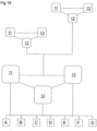
- the milking plant comprises a control arrangement forming an overall control system for controlling and supervising various functions A-G of the milking positions 1 of the milking plant, see Fig 19 .
- the various functions A-G may comprises one or more of the following functions: milk meter supervision A, pulsator rate control and supervision B, vacuum shut-off of milking vacuum C, retraction of milking cluster D, spraying disinfectant E, initiating start of milking operation F, opening and closing of gates G, etc.
- the control arrangement comprises a first control module 11, a second control module 12 and a third control module 13.
- Each of the milking positions 1 may comprise a first control module 11 and a second control module 12, whereas one third control module 13 may be configured for a plurality of milking positions 1.
- the first control module 11 is located at a convenient height for the operator below the floor 1A of the milking position 1.
- the second control module 12 is located at a height facilitating reading of the a display 64, see below.
- each of the first, second and third control modules 11-13 comprises a casing 20 comprising an inner front plate 21 and an outer rear casing 22.
- the casing 20 forms an inner space 23 between the inner front plate 21 and the outer rear casing 22.
- a printed circuit board 24, see Figs 6 and 7 is enclosed in the inner space 23.
- the outer rear casing 22 and the inner front plate 21 are assembled along a respective edge to form the inner space 23.
- a gasket 25 may be provided between the edges of the outer rear casing 22 and the inner front plate 21.
- the printed circuit board 24 incorporates at least a part of the overall control system for controlling and supervising at least some of the functions A-G mentioned above.
- the printed circuit board 24 comprises a front side 24A, see Fig 6 , and a rear side 24B, see Fig 7 . Furthermore, the printed circuit board comprises input and output connections 26 extending from the rear side 24B.
- the front side 24A of the printed circuit board 24 is attached to a rear side of the inner front plate 21 by means of a transparent adhering substance, such as a transparent glue.
- a transparent adhering substance such as a transparent glue.
- the whole surface of the front side 24A of the printed circuit board 24 has to be attached to the rear side of the inner front plate 21.
- the transparent adhering substance may be applied to certain areas of the front side 24A of the printed circuit board 24.
- This part of the printed circuit board 24 that projects from the rear side of the inner front plate 21, is embedded and molded in a block 27 of plastic material, see Fig 8 .
- the input and output connections 26 extend from the rear side 24A of the printed circuit board 24 through and beyond the block 27 of plastic material.
- the plastic material may comprise or consist of polyurethane.
- the printed circuit board 24 may then be fully embedded and enclosed by the plastic material, the transparent adhering substance and the inner front plate 21.
- the block 27 of plastic material is enclosed in an inner casing formed by an inner rear casing 29 and the inner front plate 21.
- the inner rear casing 29 and the inner front plate 21 may be joined to each other by means of screws 28, see Fig 18 .
- the inner rear casing 29 is enclosed in the casing 20 and provided between the inner front plate 21 and the outer rear casing 22.
- the inner front plate 21, with the block 27 of plastic material, the inner rear casing 29 and the outer rear casing 22 are assembled and pressed against each other by means of a number of screws 30 as can be seen in Figs 8 , 17 , 18 .
- the casing 20 may comprise one or more venting holes to permit gases and liquids to escape from the inner space 23 between the inner casing and the casing 20.
- the venting hole or holes may extend through a downwards directed surface of the outer rear casing 22 and be formed by a recess 22A through this surface, see Figs 8 , 17 , 18 .
- the first, second and third control modules 11-13 may be attached to a mounting plate 31, see Fig 2 .
- the mounting plate 31 may comprise a metal sheet.
- the casing 20 of the control modules 11-13 may then be attached to the mounting plate 31 by means of the screws 30.
- the mounting plate 31 may be provided between the inner front plate 21 and the outer rear casing 22 as shown in Fig 3 , or on the rear side of the outer rear casing 22 as shown in Fig 11 .
- the gasket 25 may seal between the inner front plate 21 and the mounting plate 31.
- An outer front plate 34 is attached to the inner front plate 21.
- the outer front plate 34 may be attached to the inner front plate 21 after the inner front plate 21 and the outer rear casing 22 have been assembled.
- the outer front plate 34 may be releasable to permit easy detachment from the inner front plate 21, irrespective of whether the mounting plate 31 is located between the inner front plate 21 and the outer rear casing 22, or behind the outer rear casing 22.
- Electric lines may be provided for connecting the printed circuit board 24 to devices performing said at least some of the functions A-G via the input and output connections 26.
- the electric lines are grouped in a number of cables 35. In Fig 4 , seven cables 35 are illustrated, but the number cables 35 may be for instance 2, 3, 4, 5, 6, 8, 9 etc. Each of the cables 35 may comprise a great number of electric lines.
- wireless communication may be used for communication between the control device and other devices. Wireless communication could, for example, be used as a redundant fallback solution when communication via electric lines fails.
- a cable clamp is provided in the casing 20.
- the cable clamp comprises a first clamp part 36 and a second clamp part 37, see Figs 9 and 10 .
- the first and second clamp parts 36, 37 form a respective cable channel 38 for each of the seven cables 35.
- Each of the cable channels 38 may have a curved extension forming a curved path for the respective cable 35, as illustrated by the dashed line 38A in Fig 10 .
- the cable clamp is provided between the inner rear casing 28 and the inner front plate 21.
- a recess 29A may be provided in the inner rear casing 29 in which the cable clamp may be received to permit the cables 35 to pass.
- a first seal 39 may be provided between the first clamp part 36 and the cables 35 and a second seal 39 may be provided between the second clamp part 37 and the cables 35. Only one of the seals 39 is illustrated in Figs 8 , 17 and 18 .
- the cable clamp is assembled by means of a number of screws 40, for instance four screws 40, wherein the cables 35 may be securely and sealingly clamped between the first and second seals 39 between the first clamp part 36 and the second claim part 37.
- the cable clamp is releasable from the casing 20, in particular from the position between the inner rear casing 28 and the inner front plate 21, which is a great advantage, and makes the installation easier.
- the cable clamp can be delivered separately with preinstalled cables 35, which are to be connected to the input and output connections 26 when inserting the cable clamp in said position when mounting the control module.
- the printed circuit board 24 comprises a number of communication areas provided on the front side 24A of the printed circuit board 24.
- the communication areas communicate with said at least part of the overall control system mentioned above, and are accessible through the transparent adhering substance.
- Each of the communication areas comprises a contact surface 41 and a light emitting surface 42.
- the printed circuit board 24 comprises four contact surface 41 and four light emitting surfaces 42.
- Each of the contact surfaces 41 can be seen as a circle on a front side of the block 27 in Fig 8 , and each of the light emitting surfaces 42 can be seen outside the circle (surrounding the circle at a distance from the same).
- the inner front plate 21 and the outer front plate 34 may be configured to permit access to the communication areas through the outer front plate 34 and through the inner front plate 21. Furthermore, the inner front plate 21 and the outer front plate 34 are configured to permit light emitted by the light emitting surface 42 to be visible from outside the casing 20.
- the contact surface 41 comprises a capacitive sensor.
- the inner front plate 21 may comprise a number of apertures 43 each giving access to a respective one the contact surface 41 and the capacitive sensor.
- the inner front plate 21 may comprise a number of light guides (not shown). Each light guide may be transparent to the light emitted by the light emitting surface 42 and may be provided opposite to the light emitting surface 42. Alternatively, the whole, or a part of, the inner front plate may be made of a material which is transparent to light.
- Each of the light guides may surround a respective one of the apertures 43.
- the outer front plate 34 may comprise at least one opening 47 providing access to the communication area.
- the control modules 11-13 may comprise at least one button 50-53, which is accessible from outside the casing 20 and acts on the contact surface 41 the communication area for initiating and/or interrupting at least one of said at least some of the functions via the electric lines.
- the first control module 11 comprises four buttons 50-53.
- a first button 50 may be the button most frequently used by the operator.
- the button 50 may be pressed for initiating various ones of the functions A-G, for instance initiating the milking operation F, for instance by applying the milking vacuum to the cluster 4 and the teatcups 5, for shutting-off the milking vacuum A, and for initiating retraction of the milking cluster D by the retraction device 6.
- the three further buttons 51-53 may, for instance, be provided for selecting the function A-G to be initiated and/or interrupted by the first button 50.
- buttons 50-53 extend through a respective one of the openings 47 through the outer front plate 34.
- Each of the buttons 50-53 comprises a respective activating pin 56 extending through the aperture 43 of the inner front plate 21.
- the activating pin 56 is moved to a position close the contact surface 41 to change the capacitance of the capacitive sensor of the contact surface 41, thereby generating a communication signal to said part of the control system.
- Each of the buttons 50-53 is biased to an outer rest position by means of a respective spring 57.
- the spring may be provided between the button 50-53 and the inner front plate 21, and surround the aperture 43, as can be seen in Fig 8 .
- the outer front plate 34 comprises a number of light zones 60 that may be provided in or surround a respective one of the openings 47.
- the light zones 60 are provided opposite to a respective one of the light emitting surfaces 42 and, when applicable, light guides (not shown) of the inner front plate 21.
- the light zones 60 are transparent to the light emitted by the light emitting surface 42, and thus the light emitted by the light emitting surface 42 of the printed circuit board 24 may be guided through the transparent adhering substance, the light guide/inner front plate 21 and the light zone 60 to be visible to the operator.
- Each of the light emitting surfaces 42 may be formed by one or more underlying LED-lights, which may be configured to generate various lights depending on the signal to be transferred to the operator.
- the lights may cover various colors, fixed light, flashing lights, circulating lights, lights moving back and forth etc.
- the control modules 11-13 may also comprise a display 64 for displaying a state of some of the functions.
- the second control module 12 see Figs 11-13 and 17 , comprises a display 64.
- the display 64 is visible from outside the casing 20.
- the display 64 is connected to the contact surface 41 of the communication area of the printed circuit board 24.
- the display 64 may be attached to the front side of the printed circuit board 24 and may be seen through a window 65 of the inner front plate 21.
- the window 65 may be provided in an aperture 43 through the inner front plate 21.
- the display 64 is visible through an opening 47 through the outer front plate 34, and may extend through the opening 47.
- buttons 66 may be incorporated in association with the display 64.
- the three buttons 66 comprises a respective touch sensitive button.
- Each of the buttons 66 may be provided for controlling the various states to be displayed on the display 64, and/or to control certain functions related to milking, preferably functions not already controlled by a first control module 11.
- the button 66 may be accessible through the window 65.
- the buttons 66 may be connected to one or more of the contact surfaces 41 of the printed circuit board 24.
- An additional printed circuit board (not disclosed) may be provided for the control of the buttons 66, wherein the additional printed circuit board communicates with the printed circuit board 24, possibly via one or more of the contact surfaces 41.
- Light to and through the buttons 66 may be provided by three light emitting members 67 incorporated in association with the display 64 and the buttons 66. The light may be guided to the respective button 66 via a light guide 68.
- the second control module 12 comprises a warning light provided above the display 64.
- the warning light comprises a row of LED lights 70 extending from the printed circuit board 24.
- the LED lights 70 are visible through the inner front plate 21 and through the outer front plate 34.
- a light directing member 71 is provided outside the LED light 70 and extends through an opening 47 through the outer front plate 34.
- One exemplifying embodiment of the third control module 13 differs from the first and second control modules 11 and 12 in that no buttons and no display are provided. This example of a third control module 13 is thus intended to operate without any interaction with the operator of the milking plant.
- the outer front plate 34 is detachable for permitting access to the capacitive sensor of the respective contact surface 41 of the printed circuit board 24 via a respective aperture 43 through the inner front plate 21 in order to permit programming of the printed circuit board 24.
- the third control module 13 may function as a router, or a link, between the other control modules 11, 12 and higher layers, such as a herd management system.
- the first and second control modules 11, 12 may instead communicate wirelessly with the herd management system, possibly via each other. This redundancy in the communication system is a great strength. Wireless communication is not considered as reliable as wired communication in the environment where the control modules 11-13 are to be mounted, but may be a good safety precaution.
- a third control module may comprise four equally sized buttons, e.g. symmetrically located over the front surface.
- Such an example of a third control module may be configured for controlling some of the functions A-G, for instance controlling the function of opening and closing of gates G.
- the buttons may be implemented in a similar manner as in the first or second control module.
- At least one light emitting surface 42 may be provided on the printed circuit board 24 and configured to emit light to indicate that the third control module 13 is operating.
- the light of the light emitting surface 42 may be guided through a light guide (not shown) provided in the inner front plate 21 opposite to the light emitting surface 42.
- the inner front plate 21 may alternatively be completely or partly made of a transparent material.
- the light guide may surround one of the aperture 43.
- the outer front plate 34 may comprise a window 74 opposite to the light guide on the inner front plate 21 in order to permit the operator to see the light emitted by the light emitting surface 42.
- the printed circuit board 24 of the first control module 11 may incorporate at least a first part of the control system for controlling and supervising at least some of the functions A-G.
- the printed circuit board 24 of the second control module 12 may incorporate at least a second part of the control system for controlling and supervising at least some of the functions A-G.
- the printed circuit board 24 of the third control module 13 may incorporate at least a third part of the control system for controlling and supervising at least some of the functions A-G.
- each individual milking position 1 the farmer may choose to install one or more control modules 11-13 in the milking position 1 depending on the control and supervising needs. For instance, each milking position 1 of a particular milking plant may be provided with only the first control module 11, which may be sufficient for controlling and supervising the functions of this particular milking plant.
- the farmer may decide to add functionality by further installing a second control unit 12 in each milking position 1, and thereby e.g. access valuable information in real time via the display.
- each milking position may comprise a first control module 11 and a second control module 12, or a first control module 11 and a third control module 13, or a second control module 12 and a third control module 13.
- the types of third control module mainly described herein are intended to serve a plurality of milking positions 1.
- each milking position 1 may comprise a first control module 11 and a second control module 12, whereas the third control module 13 may be configured to operate together with a number of milking positions 1.
- control module 11-13 With more than one control module 11-13, it is possible to transfer the duties of a control module 11-13 that is defect or out of service for any other reason to the other control modules. Such a transfer of duties may take place in an automatic manner, and is indicated by the lines connecting the control modules 11-13 in Fig 19 to each other.
- Fig 19 also illustrates that the control system of one milking place 1, may communicate with the control system of other milking positions 1 of the milking plant. If the control system of one milking position 1 is not operating properly one or more of the functions A-G may be performed by the control system of any other milking position 1.
- the first part of the control system operated by the first control module 11, the second part of the control system operated by the second control module 12, and the third part of the control system operated by the third control module 13 may be overlapping, or at least partly overlapping.
- the first part of the control system, the second part of the control system and the third part of the control system may cover, or at least partly cover, the same functions A-G of the milking plant.
- the first part of the control system, the second part of the control system and the third part of the control system may be identical, or substantially identical.
- several parts of the different control modules 11-13 may be identical.
- the printed circuit boards 24 may be identical, comprising all functions necessary for the functions of all three control modules 11-13, but only using the parts necessary for the relevant control module 11-13 in which it is mounted
Landscapes
- Engineering & Computer Science (AREA)
- Microelectronics & Electronic Packaging (AREA)
- Life Sciences & Earth Sciences (AREA)
- Animal Husbandry (AREA)
- Environmental Sciences (AREA)
- External Artificial Organs (AREA)
Description
- The present invention refers generally to a control module for a milking position and to a control arrangement for a milking plant. More specifically, and according to the preamble of
claim 1, the present invention refers to a control module for controlling and supervising various functions of a milking position for milking a respective dairy animal. - The present invention also refers to a control arrangement forming an overall control system for controlling and supervising various functions of a milking plant incorporating a plurality of milking positions for milking a respective dairy animal.
- Known control arrangements for milking plants require fairly extensive installation work in order to be properly adapted to the specific requirements of the milking plant and to various preferences of the individual farmer. For instance, the known control arrangements are not always well adapted to milking plants of different sizes and kinds, and not to the various functions to be controlled and supervised at each milking position of a milking plant. In particular, known control arrangements may not in an easy manner permit addition of further control and supervising functions once they have been installed, or conversely, they may contain more control and supervising functions than demanded by the farmer.
- Another problem of the known control arrangements is related to the fact that the milking plants constitute a very difficult environment for electronic control equipment. Humidity and various harmful substances may circulate in the air in the milking plant and may deteriorate the reliability and the functioning of the electronic equipment of the control arrangement.
- Another problem of the known control arrangements is that it is difficult to locate them in an ergonomic position for the staff performing the milking. A position which is suitable for e.g. pushing buttons is not necessarily suitable for e.g. viewing and reading instructions/feedback, and vice versa.
-
WO 2008/051134 discloses an arrangement provided in a milking system for simultaneous milking of a plurality of animals, wherein the milking system comprises a plurality of milking positions and an arrangement for establishing identities of and expected milking times for the animals. Each of the milking positions is provided with teatcups, which are attached to the teats of an animal and are connected to a source of vacuum for milking the animal. The arrangement comprises means for determining a milking position, at which the animal having the longest expected milking time is present, based on the established identities and expected milking times, and a device for performing an action with respect to the milking system in response to the determination. -
WO 2006/068589 refers to a compact modular unit to be mounted in a milking stall comprising at least one pipeline system, which provides an operative function in connection with a milking process of an animal in the milking stall. The compact modular unit comprises a casing, which defines an inner space of the compact modular unit, an electric control unit, which is mounted in said inner space of the compact modular unit, and indication means, which are arranged to display information related to the milking processes in the milking stall. Furthermore, the compact modular unit comprises a component of the pipeline system, which is mounted in the inner space of the compact modular unit. - A further publication
CN 205 644 162 U discloses a universal intelligent milking controller comprising a casing and communication module. - The purpose of the present invention is to provide a solution to the problems discussed above, and more precisely to provide improved means for controlling and supervising a milking position of a milking plant, and for controlling and supervising a milking plant comprising a plurality of milking position.
- This purpose is achieved by the control module initially defined, which is characterized in that the casing comprises an inner front plate, that the front side of the printed circuit is attached to a rear side of the inner front plate by means of a transparent adhering substance, for instance a transparent glue, so that at least a the part of the printed circuit board projects from the rear side of the inner front plate, that the inner front casing plate permits access to the communication area through the inner front plate, and that said part of the printed circuit board is embedded in a block of plastic material.
- By enclosing the printed circuit board of the control module in the block of plastic material, the transparent adhering substance and the inner front plate, and in the casing, the resistance to humidity and harmful substances of the environment may be enhanced. Especially, by the enclosing of the printed circuit board and the connections against the environment, the control module may withstand the washing procedure of the milking position when water, or any other washing liquid, is sprayed onto the equipment, including the control module, frequently under high pressure. The block of plastic material provides a good protection to the printed circuit board inside the casing, even if humidity and any harmful substance would reach the inner space of the casing. The plastic material may comprise or consist of polyurethane.
- According to an embodiment of the invention, the functions comprise at least one of the following functions: milk meter supervision, pulsator rate control and supervision, vacuum shut-off of milking vacuum, retraction of milking cluster, spraying disinfectant, initiating start of milking operation, opening and closing of gates, etc.
- According to an embodiment of the invention, the casing comprises an outer rear casing that together with the inner front plate encloses the inner space.
- According to an embodiment of the invention, the outer rear casing and the inner front plate are assembled along a respective edge to form the inner space. A gasket may be provided between the edges of the outer rear casing and the inner front plate.
- According to an embodiment of the invention, wherein the input and output connections extend from the printed circuit board, or from the rear side of the printed circuit board, through and beyond the block of plastic material. The input and output connections may be enclosed in the casing.
- According to an embodiment of the invention, the communication area comprises a contact surface and a light emitting surface, wherein light emitted by the light emitting surface is visible from outside the casing. The communication area is accessible through the inner front plate and the transparent adhering substance.
- According to an embodiment of the invention, the light emitting surface emits different light signals for indicating various states of some of the functions. These states may include, for instance, a full milk flow, washing is ongoing, a waiting state, a standby state, an alarm etc. The different light signals may include light of different colors, flashing light, circulating light, light moving back and forth etc.
- According to an embodiment of the invention, the control module comprises at least one button, which is accessible from outside the casing and acts on the contact surface for initiating and/or interrupting one of the functions via the electric lines. For instance, by activating the button, start of the milking operation may be initiated, or the milking vacuum may be shut-off and retraction of the milking cluster initiated.
- According to an embodiment of the invention, one or more further buttons, accessible from outside the casing and acting on the contact surface, may be provided for selecting the function to be initiated and/or interrupted by said button.
- According to an embodiment of the invention, the control module comprises a display, which is visible from outside the casing and is connected to the contact surface of the communication area for displaying a state of some of the functions.
- According to an embodiment of the invention, the inner front plate comprises at least one light guide, which is transparent to the light emitted by the light emitting surface and provided opposite to the light emitting surface.
- According to an embodiment of the invention, the inner front plate comprises an aperture giving access to the contact surface.
- According to an embodiment of the invention, the light guide surrounds the aperture. The light guide may thus surround the button, so that a ring of different light signals may be formed around the button.
- According to an embodiment of the invention, the block of plastic material is enclosed in an inner casing formed by an inner rear casing and the inner front plate, wherein the inner rear casing is enclosed in the casing. Such an inner casing further improves the protection against the environment of the milking plant, and during the above-mentioned washing procedure.
- According to an embodiment of the invention, the casing may comprise one or more venting holes to permit gases and liquids to escape from the inner space between the inner casing and the casing. This is advantageous, especially during the above-mentioned washing procedure.
- According to an embodiment of the invention, an outer front plate is attached to the inner front plate and comprises an opening providing access to the communication area.
- According to an embodiment of the invention, the button extends through the opening, and wherein the outer front plate comprises a light zone that surrounds the opening, is transparent to the light emitted by the light emitting surface, and is provided opposite to the light emitting surface.
- According to an embodiment of the invention, the electric lines are grouped in at least two cables, for instance two, three, four, five, six, etc. cables. Such preprepared cables are easy to install and may contribute to a more efficient installation of the control arrangement. Each cable may comprise an insulation, or a tight insulation, enclosing the respective electric lines, especially a large number of electric lines running within the insulation of each cable. In other words, the control module is adapted to receive a plurality of cables, each comprising a plurality of electric lines, to which the module is connectable.
- According to an embodiment of the invention, a cable clamp is provided in the casing and comprises a first clamp part and a second clamp part, wherein the first and second clamp parts form a respective cable channel for each of said at least two cables.
- According to an embodiment of the invention, the cable clamp is provided between the inner rear casing and the inner front plate. The cable clamp my thus be located at least partly in the inner space. A recess may be provided in the inner rear casing permitting the cables to pass therethrough.
- According to an embodiment of the invention, each of the cable channels has a curved extension forming a curved, or bent, path for the respective cable. Such curved extension may contribute to a firm and tight engagement of the cables in the cable clamp, and may prevent water from entering via the cable channel.
- The purpose is also achieved by the control arrangement initially defined, wherein the first control module comprises a control module as described above and wherein the printed circuit board incorporates at least a first part of the control system for controlling and supervising at least some of the functions.
- According to an embodiment of the invention, the control arrangement comprises a respective second control module for each of the milking positions, wherein the second control module comprises a control module as described above, wherein the printed circuit board incorporates at least a second part of the control system for controlling and supervising at least some of the functions.
- Thanks to the second control module, the flexibility of the control arrangement is improved. In each individual milking position, the farmer may choose to install one or more control modules in the milking position depending on the control and supervising needs.
- Thanks to the second control module, or even further control modules, it is, in case of a defect control module, only necessary to repair or replace the defect control module. The costs for repair and maintenance may be reduced.
- According to an embodiment of the invention, the first part of the control system and the second part of the control system are overlapping, or at least partly overlapping, wherein the first part of the control system and the second part of the control system at least partly cover the same functions. Possibly, the first part and the second part of the control system may be identical, although different functions may be activated in the different parts. This means that the control system may have a redundant functionality and be configured to operate unaffected, at least temporarily, even if one of the control modules is defect. The defect control module may be repaired or replaced without the need to shut down the control system. Consequently, the costs for repair and maintenance may be reduced.
- In particular, the printed circuit board of the control modules may be identical, or substantially identical.
- According to an embodiment of the invention, the control arrangement comprises a respective third control module for at least some of the milking positions, wherein the third control module comprises a control module as described above, and wherein the printed circuit board, incorporating at least a third part of the control system for controlling and supervising at least some of the functions. The third control module may be configured for controlling the function of for example the opening and closing of the gates. The third control module may alternatively, or in addition, have the function of a router, handling the communication between modules, mounted in a number of milking positions (e.g. first and/or second modules), and other functions or equipment, such as e.g. a herd management system. One third control module may serve a plurality of milking positions, e.g. 5-50 milking positions.
- By introducing a third module the flexibility of the control arrangement is further enhanced.
- According to an embodiment of the invention, the first part of the control system, the second part of the control system and the third part of the control system are overlapping, or at least partly overlapping, and wherein the first part of the control system, the second part of the control system, and the third part of the control system at least partly cover the same functions. Possibly, the first part, the second part and the third part of the control system may be identical.
- In particular, the printed circuit board of the first, second and third modules may be identical, or substantially identical.
- According to an embodiment of the invention, a display is provided on the casing of the second module, wherein the display is connected to the communication area and arranged for displaying a state of some of the functions. A display may also be provided on the casing of the first module and/or third module.
- The present invention is now to be explained more closely by the description of various embodiments and with reference to the drawings attached hereto.
- Fig 1
- discloses schematically a view from above of a milking plant.
- Fig 2
- discloses schematically a rear view of a milking position of the milking plant in
Fig 1 . - Fig 3
- discloses schematically a side view of a first control module of a control arrangement for controlling and supervising various functions of the milking plant in
Fig 1 . - Fig 4
- discloses schematically a front view of the first control module in
Fig 3 . - Fig 5
- discloses schematically a perspective view of the first control module in
Fig 3 . - Fig 6
- discloses a front view a printed circuit board of the first control module.
- Fig 7
- discloses a rear view the printed circuit board in
Fig 6 . - Fig 8
- discloses an exploded perspective view of the first control module in
Fig 3 . - Fig 9
- discloses a first perspective view of a cable clamp of the first control module in
Fig 3 . - Fig 10
- discloses a second perspective view of the cable clamp in
Fig 9 . - Fig 11
- discloses schematically a side view of a second control module of the control arrangement.
- Fig 12
- discloses schematically a front view of the second control module in
Fig 11 . - Fig 13
- discloses schematically a perspective view of the second control module in
Fig 11 . - Fig 14
- discloses schematically a side view of a third control module of the control arrangement.
- Fig 15
- discloses schematically a front view of the third control module in
Fig 14 . - Fig 16
- discloses schematically a perspective view of the third control module in
Fig 14 . - Fig 17
- discloses an exploded perspective view of the second control module in
Fig 11 . - Fig 18
- discloses an exploded perspective view of the third control module in
Fig 3 . - Fig 19
- discloses a diagram of a control arrangement for the milking position and at least a part of the milking plant.
-
Fig 1 discloses a milking plant comprising a plurality of milking positions 1. Eachmilking position 1 is configured to house a diary animal. Eachmilking position 1 or a group of milkingpositions 1 may be delimited byfloor 1A, and a bar andgate structure 2 which may comprise anopenable gate 3. -
Fig 2 discloses one of the milking positions of the milking plant. Each of the milking positions 1 comprises a milkingcluster 4 having a plurality ofteatcups 5, for instance two or fourteatcups 5, to be attached to the teats of the diary animal to be milked. Eachmilking position 1 may also comprise aretraction device 6 for retracting the milkingcluster 4 when the milking operation is finished. Furthermore, each milkingposition 1 may comprise aspraying device 7 for spraying disinfectant to the teats of the diary animal. - The milking plant comprises a control arrangement forming an overall control system for controlling and supervising various functions A-G of the milking
positions 1 of the milking plant, seeFig 19 . The various functions A-G may comprises one or more of the following functions: milk meter supervision A, pulsator rate control and supervision B, vacuum shut-off of milking vacuum C, retraction of milking cluster D, spraying disinfectant E, initiating start of milking operation F, opening and closing of gates G, etc. - In an exemplifying embodiment, the control arrangement comprises a
first control module 11, asecond control module 12 and athird control module 13. Each of the milkingpositions 1 may comprise afirst control module 11 and asecond control module 12, whereas onethird control module 13 may be configured for a plurality of milking positions 1. - In said exemplifying embodiment, the
first control module 11 is located at a convenient height for the operator below thefloor 1A of themilking position 1. Thesecond control module 12 is located at a height facilitating reading of the adisplay 64, see below. - With reference to
Figs 8 ,17 and18 , each of the first, second and third control modules 11-13 comprises acasing 20 comprising an innerfront plate 21 and an outerrear casing 22. Thecasing 20 forms aninner space 23 between the innerfront plate 21 and the outerrear casing 22. A printedcircuit board 24, seeFigs 6 and 7 , is enclosed in theinner space 23. The outerrear casing 22 and the innerfront plate 21 are assembled along a respective edge to form theinner space 23. Agasket 25 may be provided between the edges of the outerrear casing 22 and the innerfront plate 21. - The printed
circuit board 24 incorporates at least a part of the overall control system for controlling and supervising at least some of the functions A-G mentioned above. - The printed
circuit board 24 comprises afront side 24A, seeFig 6 , and arear side 24B, seeFig 7 . Furthermore, the printed circuit board comprises input andoutput connections 26 extending from therear side 24B. - The
front side 24A of the printedcircuit board 24 is attached to a rear side of the innerfront plate 21 by means of a transparent adhering substance, such as a transparent glue. Thus, a part of the printedcircuit board 24, that is not attached to the innerfront plate 21, projects from the rear side of the innerfront plate 21. - It should be noted that not the whole surface of the
front side 24A of the printedcircuit board 24 has to be attached to the rear side of the innerfront plate 21. The transparent adhering substance may be applied to certain areas of thefront side 24A of the printedcircuit board 24. - This part of the printed
circuit board 24 that projects from the rear side of the innerfront plate 21, is embedded and molded in ablock 27 of plastic material, seeFig 8 . The input andoutput connections 26 extend from therear side 24A of the printedcircuit board 24 through and beyond theblock 27 of plastic material. The plastic material may comprise or consist of polyurethane. The printedcircuit board 24 may then be fully embedded and enclosed by the plastic material, the transparent adhering substance and the innerfront plate 21. - The
block 27 of plastic material is enclosed in an inner casing formed by an innerrear casing 29 and the innerfront plate 21. The innerrear casing 29 and the innerfront plate 21 may be joined to each other by means ofscrews 28, seeFig 18 . The innerrear casing 29 is enclosed in thecasing 20 and provided between the innerfront plate 21 and the outerrear casing 22. - The inner
front plate 21, with theblock 27 of plastic material, the innerrear casing 29 and the outerrear casing 22 are assembled and pressed against each other by means of a number ofscrews 30 as can be seen inFigs 8 ,17 ,18 . Thecasing 20 may comprise one or more venting holes to permit gases and liquids to escape from theinner space 23 between the inner casing and thecasing 20. The venting hole or holes may extend through a downwards directed surface of the outerrear casing 22 and be formed by arecess 22A through this surface, seeFigs 8 ,17 ,18 . - The first, second and third control modules 11-13 may be attached to a mounting
plate 31, seeFig 2 . The mountingplate 31 may comprise a metal sheet. Thecasing 20 of the control modules 11-13 may then be attached to the mountingplate 31 by means of thescrews 30. The mountingplate 31 may be provided between the innerfront plate 21 and the outerrear casing 22 as shown inFig 3 , or on the rear side of the outerrear casing 22 as shown inFig 11 . In the first case, thegasket 25 may seal between the innerfront plate 21 and the mountingplate 31. - An outer
front plate 34 is attached to the innerfront plate 21. The outerfront plate 34 may be attached to the innerfront plate 21 after the innerfront plate 21 and the outerrear casing 22 have been assembled. The outerfront plate 34 may be releasable to permit easy detachment from the innerfront plate 21, irrespective of whether the mountingplate 31 is located between the innerfront plate 21 and the outerrear casing 22, or behind the outerrear casing 22. - Electric lines may be provided for connecting the printed
circuit board 24 to devices performing said at least some of the functions A-G via the input andoutput connections 26. The electric lines are grouped in a number ofcables 35. InFig 4 , sevencables 35 are illustrated, but thenumber cables 35 may be forinstance cables 35 may comprise a great number of electric lines. Alternatively or in addition, wireless communication may be used for communication between the control device and other devices. Wireless communication could, for example, be used as a redundant fallback solution when communication via electric lines fails. - A cable clamp is provided in the
casing 20. The cable clamp comprises afirst clamp part 36 and asecond clamp part 37, seeFigs 9 and 10 . The first andsecond clamp parts respective cable channel 38 for each of the sevencables 35. Each of thecable channels 38 may have a curved extension forming a curved path for therespective cable 35, as illustrated by the dashedline 38A inFig 10 . - The cable clamp is provided between the inner
rear casing 28 and the innerfront plate 21. Arecess 29A may be provided in the innerrear casing 29 in which the cable clamp may be received to permit thecables 35 to pass. - A
first seal 39 may be provided between thefirst clamp part 36 and thecables 35 and asecond seal 39 may be provided between thesecond clamp part 37 and thecables 35. Only one of theseals 39 is illustrated inFigs 8 ,17 and18 . The cable clamp is assembled by means of a number ofscrews 40, for instance fourscrews 40, wherein thecables 35 may be securely and sealingly clamped between the first andsecond seals 39 between thefirst clamp part 36 and thesecond claim part 37. The cable clamp is releasable from thecasing 20, in particular from the position between the innerrear casing 28 and the innerfront plate 21, which is a great advantage, and makes the installation easier. For example, the cable clamp can be delivered separately with preinstalledcables 35, which are to be connected to the input andoutput connections 26 when inserting the cable clamp in said position when mounting the control module. - The printed
circuit board 24 comprises a number of communication areas provided on thefront side 24A of the printedcircuit board 24. The communication areas communicate with said at least part of the overall control system mentioned above, and are accessible through the transparent adhering substance. Each of the communication areas comprises acontact surface 41 and alight emitting surface 42. In thefirst control module 11, the printedcircuit board 24 comprises fourcontact surface 41 and four light emitting surfaces 42. Each of the contact surfaces 41 can be seen as a circle on a front side of theblock 27 inFig 8 , and each of thelight emitting surfaces 42 can be seen outside the circle (surrounding the circle at a distance from the same). - The inner
front plate 21 and the outerfront plate 34 may be configured to permit access to the communication areas through the outerfront plate 34 and through the innerfront plate 21. Furthermore, the innerfront plate 21 and the outerfront plate 34 are configured to permit light emitted by thelight emitting surface 42 to be visible from outside thecasing 20. - The
contact surface 41 comprises a capacitive sensor. The innerfront plate 21 may comprise a number ofapertures 43 each giving access to a respective one thecontact surface 41 and the capacitive sensor. - The inner
front plate 21 may comprise a number of light guides (not shown). Each light guide may be transparent to the light emitted by thelight emitting surface 42 and may be provided opposite to thelight emitting surface 42. Alternatively, the whole, or a part of, the inner front plate may be made of a material which is transparent to light. - Each of the light guides (not shown) may surround a respective one of the
apertures 43. - Also the outer
front plate 34 may comprise at least oneopening 47 providing access to the communication area. - The control modules 11-13 may comprise at least one button 50-53, which is accessible from outside the
casing 20 and acts on thecontact surface 41 the communication area for initiating and/or interrupting at least one of said at least some of the functions via the electric lines. - The
first control module 11 comprises four buttons 50-53. Afirst button 50 may be the button most frequently used by the operator. Thebutton 50 may be pressed for initiating various ones of the functions A-G, for instance initiating the milking operation F, for instance by applying the milking vacuum to thecluster 4 and theteatcups 5, for shutting-off the milking vacuum A, and for initiating retraction of the milking cluster D by theretraction device 6. The three further buttons 51-53 may, for instance, be provided for selecting the function A-G to be initiated and/or interrupted by thefirst button 50. - The buttons 50-53 extend through a respective one of the
openings 47 through the outerfront plate 34. Each of the buttons 50-53 comprises a respective activatingpin 56 extending through theaperture 43 of the innerfront plate 21. When the button 50-53 is pressed, the activatingpin 56 is moved to a position close thecontact surface 41 to change the capacitance of the capacitive sensor of thecontact surface 41, thereby generating a communication signal to said part of the control system. - Each of the buttons 50-53 is biased to an outer rest position by means of a
respective spring 57. The spring may be provided between the button 50-53 and the innerfront plate 21, and surround theaperture 43, as can be seen inFig 8 . - The outer
front plate 34 comprises a number oflight zones 60 that may be provided in or surround a respective one of theopenings 47. Thelight zones 60 are provided opposite to a respective one of thelight emitting surfaces 42 and, when applicable, light guides (not shown) of the innerfront plate 21. Thelight zones 60 are transparent to the light emitted by thelight emitting surface 42, and thus the light emitted by thelight emitting surface 42 of the printedcircuit board 24 may be guided through the transparent adhering substance, the light guide/innerfront plate 21 and thelight zone 60 to be visible to the operator. - Each of the
light emitting surfaces 42 may be formed by one or more underlying LED-lights, which may be configured to generate various lights depending on the signal to be transferred to the operator. The lights may cover various colors, fixed light, flashing lights, circulating lights, lights moving back and forth etc. - The control modules 11-13 may also comprise a
display 64 for displaying a state of some of the functions. - The
second control module 12, seeFigs 11-13 and17 , comprises adisplay 64. Thedisplay 64 is visible from outside thecasing 20. Thedisplay 64 is connected to thecontact surface 41 of the communication area of the printedcircuit board 24. - As can be seen in
Fig 17 , thedisplay 64 may be attached to the front side of the printedcircuit board 24 and may be seen through awindow 65 of the innerfront plate 21. Thewindow 65 may be provided in anaperture 43 through the innerfront plate 21. - The
display 64 is visible through anopening 47 through the outerfront plate 34, and may extend through theopening 47. - Three
buttons 66 may be incorporated in association with thedisplay 64. The threebuttons 66 comprises a respective touch sensitive button. Each of thebuttons 66 may be provided for controlling the various states to be displayed on thedisplay 64, and/or to control certain functions related to milking, preferably functions not already controlled by afirst control module 11. Thebutton 66 may be accessible through thewindow 65. - The
buttons 66 may be connected to one or more of the contact surfaces 41 of the printedcircuit board 24. An additional printed circuit board (not disclosed) may be provided for the control of thebuttons 66, wherein the additional printed circuit board communicates with the printedcircuit board 24, possibly via one or more of the contact surfaces 41. - Light to and through the
buttons 66 may be provided by three light emittingmembers 67 incorporated in association with thedisplay 64 and thebuttons 66. The light may be guided to therespective button 66 via alight guide 68. - In addition, the
second control module 12 comprises a warning light provided above thedisplay 64. The warning light comprises a row ofLED lights 70 extending from the printedcircuit board 24. The LED lights 70 are visible through the innerfront plate 21 and through the outerfront plate 34. Alight directing member 71 is provided outside theLED light 70 and extends through anopening 47 through the outerfront plate 34. - One exemplifying embodiment of the
third control module 13, seeFigs 14-16 and 18, differs from the first andsecond control modules third control module 13 is thus intended to operate without any interaction with the operator of the milking plant. - However, the outer
front plate 34 is detachable for permitting access to the capacitive sensor of therespective contact surface 41 of the printedcircuit board 24 via arespective aperture 43 through the innerfront plate 21 in order to permit programming of the printedcircuit board 24. - The
third control module 13 may function as a router, or a link, between theother control modules - If the function of a
third control module 13 fails, the first andsecond control modules - Another embodiment of a third control module may comprise four equally sized buttons, e.g. symmetrically located over the front surface. Such an example of a third control module may be configured for controlling some of the functions A-G, for instance controlling the function of opening and closing of gates G. The buttons may be implemented in a similar manner as in the first or second control module.
- At least one
light emitting surface 42 may be provided on the printedcircuit board 24 and configured to emit light to indicate that thethird control module 13 is operating. The light of thelight emitting surface 42 may be guided through a light guide (not shown) provided in the innerfront plate 21 opposite to thelight emitting surface 42. As before, the innerfront plate 21 may alternatively be completely or partly made of a transparent material. The light guide may surround one of theaperture 43. - The outer
front plate 34 may comprise awindow 74 opposite to the light guide on the innerfront plate 21 in order to permit the operator to see the light emitted by thelight emitting surface 42. - The printed
circuit board 24 of thefirst control module 11 may incorporate at least a first part of the control system for controlling and supervising at least some of the functions A-G. - The printed
circuit board 24 of thesecond control module 12 may incorporate at least a second part of the control system for controlling and supervising at least some of the functions A-G. - The printed
circuit board 24 of thethird control module 13 may incorporate at least a third part of the control system for controlling and supervising at least some of the functions A-G. - Thanks to the three
control modules individual milking position 1, the farmer may choose to install one or more control modules 11-13 in themilking position 1 depending on the control and supervising needs. For instance, each milkingposition 1 of a particular milking plant may be provided with only thefirst control module 11, which may be sufficient for controlling and supervising the functions of this particular milking plant. At a later point in time, the farmer may decide to add functionality by further installing asecond control unit 12 in eachmilking position 1, and thereby e.g. access valuable information in real time via the display. - In another case, each milking position may comprise a
first control module 11 and asecond control module 12, or afirst control module 11 and athird control module 13, or asecond control module 12 and athird control module 13. However, the types of third control module mainly described herein are intended to serve a plurality of milking positions 1. - It is also possible to have different number of control modules in the
different milking positions 1 of the milking plant. For instance, each milkingposition 1 may comprise afirst control module 11 and asecond control module 12, whereas thethird control module 13 may be configured to operate together with a number of milking positions 1. - With more than one control module 11-13, it is possible to transfer the duties of a control module 11-13 that is defect or out of service for any other reason to the other control modules. Such a transfer of duties may take place in an automatic manner, and is indicated by the lines connecting the control modules 11-13 in
Fig 19 to each other. -
Fig 19 also illustrates that the control system of onemilking place 1, may communicate with the control system ofother milking positions 1 of the milking plant. If the control system of onemilking position 1 is not operating properly one or more of the functions A-G may be performed by the control system of anyother milking position 1. - Consequently, the first part of the control system operated by the
first control module 11, the second part of the control system operated by thesecond control module 12, and the third part of the control system operated by thethird control module 13 may be overlapping, or at least partly overlapping. Thus, the first part of the control system, the second part of the control system and the third part of the control system may cover, or at least partly cover, the same functions A-G of the milking plant. - In particular, the first part of the control system, the second part of the control system and the third part of the control system may be identical, or substantially identical. For reasons of production economy, several parts of the different control modules 11-13 may be identical. Even the printed
circuit boards 24 may be identical, comprising all functions necessary for the functions of all three control modules 11-13, but only using the parts necessary for the relevant control module 11-13 in which it is mounted - The invention is not limited to the embodiments disclosed, but may be varied and modified within the scope of the following claims.
Claims (16)
- A control module (11, 12, 13) for controlling and supervising various functions of a milking position for milking a dairy animal, wherein the control module comprises- a casing (20) forming an inner space (23) enclosing a printed circuit board (24), incorporating at least a part of a control system for controlling and supervising at least some of the functions and comprising input and output connections (26), wherein the printed circuit board (24) comprises a front side (24A) and a rear side (24B), wherein at least one communication area is provided on front side (24A) of the printed circuit board (24) and communicates with said part of the control system, and wherein the printed circuit board (24) is connectable to said at least some of the functions via the input and output connections (26) by means of electric lines,characterized inthat the casing (20) comprises an inner front plate (21),that the front side (24A) of the printed circuit board (24) is attached to a rear side of the inner front plate (21) by means of a transparent adhering substance so that at least a part of the printed circuit board (24) projects from the rear side of the inner front plate (21),that the inner front plate (21) permits access to the communication area through the inner front plate (21), andthat said part of the printed circuit board (24) is embedded in a block (27) of plastic material.
- The control module according to claim 1, wherein the input and output connections (26) extend from the printed circuit board (24) through and beyond the block (27) of plastic material.
- The control module according to any one of claims 1 and 2, wherein the communication area comprises a contact surface (41) and a light emitting surface (42, 68), wherein light emitted by the light emitting surface (42, 68) is visible from outside the casing (20), wherein the control module comprises at least one button (50-53, 66), which is accessible from outside the casing (20) and acts on the contact surface (41) of the communication area for initiating and/or interrupting at least one of said at least some of the functions, wherein the inner front plate (21) is transparent to the light emitted by the light emitting surface (42) at least in a position opposite to the light emitting surface (42).
- The control module according to claim 3, wherein the control module comprises a display (64), which is visible from outside the casing (20) and is connected to the contact surface (41) of the communication area for displaying a state of some of the functions.
- The control module according to any one of claims 3 or 4, wherein the inner front plate (21) comprises an aperture (43) giving access to the contact surface (41).
- The control module according to claim 5, wherein a light guide, which is transparent to the light emitted by the light emitting surface (42) surrounds the aperture (43).
- The control module according to any one of the preceding claims, wherein the block (27) of plastic material is enclosed in an inner casing formed by an inner rear casing (29) and the inner front plate (21), and wherein the inner rear casing (29) is enclosed in the casing (20).
- The control module according to any one of the preceding claims, wherein an outer front plate (34) is attached to the inner front plate (21) and comprises at least one opening (47) providing access to the communication area.
- The control module according to claims 3 and 8, wherein the button (50-53) extends through the opening (47), and wherein the outer front plate (34) comprises a light zone (60) that surrounds the opening (47), is transparent to the light emitted by the light emitting surface (42), and is provided opposite to the light emitting surface (42).
- The control module according to any one of the preceding claims, being configured to receive electric lines grouped in at least two cables (35).
- The control module according to claim 10, wherein a cable clamp is provided in the casing (20) and comprises a first clamp part (36) and a second clamp part (37), and wherein the first and second clamp parts (36, 37) form a respective cable channel (38) for each of said at least two cables (35).
- The control module according to claims 7 and 11, wherein the cable clamp is provided between the inner rear casing (29) and the inner front plate (21).
- The control module according to any one of claims 11 and 12, wherein each of the cable channels (38) has a curved extension forming a curved path for the respective cable (35).
- A control arrangement forming an overall control system for controlling and supervising various functions of a milking plant incorporating a plurality of milking positions (1) for milking a respective dairy animal, wherein the control arrangement comprises a respective first control module (11) for each of the milking positions (1), wherein the first control module (11) comprises a control module according to any one of claims 1-13 and wherein the printed circuit board (24) incorporates at least a first part of the control system for controlling and supervising at least some of the functions.
- The control arrangement according to claim 14, wherein the control arrangement comprises a respective second control module (12) for each of the milking positions (1), wherein the second control module (12) comprises a control module according to any one of claims 1-13, and wherein the printed circuit board (24) incorporates at least a second part of the control system for controlling and supervising at least some of the functions.
- The control arrangement according to claim 15, wherein the first part of the control system and the second part of the control system are overlapping or at least partly overlapping, and wherein the first part of the control system and the second part of the control system at least partly cover the same functions.
Applications Claiming Priority (2)
| Application Number | Priority Date | Filing Date | Title |
|---|---|---|---|
| SE1800215 | 2018-11-08 | ||
| PCT/SE2019/051127 WO2020096517A1 (en) | 2018-11-08 | 2019-11-08 | A control module, and a control arrangement for a milking plant |
Publications (2)
| Publication Number | Publication Date |
|---|---|
| EP3878251A1 EP3878251A1 (en) | 2021-09-15 |
| EP3878251B1 true EP3878251B1 (en) | 2024-01-24 |
Family
ID=68583485
Family Applications (1)
| Application Number | Title | Priority Date | Filing Date |
|---|---|---|---|
| EP19805420.7A Active EP3878251B1 (en) | 2018-11-08 | 2019-11-08 | A control module, and a control arrangement for a milking plant |
Country Status (5)
| Country | Link |
|---|---|
| US (1) | US11864528B2 (en) |
| EP (1) | EP3878251B1 (en) |
| CN (1) | CN113016238B (en) |
| CA (1) | CA3119082A1 (en) |
| WO (1) | WO2020096517A1 (en) |
Families Citing this family (1)
| Publication number | Priority date | Publication date | Assignee | Title |
|---|---|---|---|---|
| DE202022104035U1 (en) * | 2022-07-18 | 2023-10-23 | Gea Farm Technologies Gmbh | Milking device with a tight housing |
Family Cites Families (35)
| Publication number | Priority date | Publication date | Assignee | Title |
|---|---|---|---|---|
| US4922855A (en) * | 1988-05-24 | 1990-05-08 | Orion Machinery Co., Ltd. | Milking machine |
| DE19819287A1 (en) * | 1997-04-30 | 1998-11-05 | Leonische Drahtwerke Ag | Electrical component used as pocket calculator |
| US6560513B2 (en) * | 1999-11-19 | 2003-05-06 | Fanuc Robotics North America | Robotic system with teach pendant |
| US6307749B1 (en) | 2000-10-23 | 2001-10-23 | Delphi Technologies, Inc. | Overmolded electronic module with underfilled surface-mount components |
| US6741942B2 (en) * | 2002-01-07 | 2004-05-25 | S.A.E. Afikim | Free-flow fluid measurement meter |
| US20040012936A1 (en) * | 2002-07-18 | 2004-01-22 | Gravelin Pascal A. | Device and method for enclosure of electronic printed circuit board based products |
| NL1021430C1 (en) * | 2002-08-06 | 2004-02-10 | Lely Entpr Ag | Device for monitoring a milk tank, assembly of a milking robot with automatic start-up device and such a device. |
| US7140551B2 (en) * | 2004-03-01 | 2006-11-28 | Honeywell International Inc. | HVAC controller |
| US7710714B2 (en) | 2004-09-13 | 2010-05-04 | Bettcher Industries, Inc. | Housing for scale or load cell controller |
| SE0403131D0 (en) | 2004-12-22 | 2004-12-22 | Delaval Holding Ab | A compact modular unit and a milking stall including such a compact modular unit |
| NL1030295C2 (en) | 2005-10-28 | 2007-05-03 | Fei Co | Hermetically sealed housing with electrical lead-through. |
| CA2561807A1 (en) * | 2006-06-09 | 2007-12-09 | Dairy Controls International, Inc. | In-line apparatus and real-time method to determine milk characteristics |
| US7699024B2 (en) * | 2006-09-20 | 2010-04-20 | Rysewyk Terry P | Milk temperature monitor with ambient temperature compensation |
| US20090320759A1 (en) | 2006-10-23 | 2009-12-31 | Johan Odeberg | Arrangements and method in a milking system |
| CN101351062A (en) * | 2007-07-22 | 2009-01-21 | 余建宇 | Method for manufacturing LED indicating lamp and LED indicating lamp using the method |
| KR101296426B1 (en) | 2008-07-28 | 2013-08-13 | 티알더블유 오토모티브 유.에스. 엘엘씨 | Method and apparatus for packaging crash sensors |
| JP2010266117A (en) | 2009-05-14 | 2010-11-25 | Daikin Ind Ltd | Operating device and method of mounting the operating device on the wall |
| US9277728B2 (en) * | 2010-06-14 | 2016-03-08 | Gea Farm Technologies Gmbh | Milking apparatus and system |
| DE102010039185A1 (en) | 2010-08-11 | 2012-02-16 | Robert Bosch Gmbh | Electrical connection arrangement |
| US8800486B2 (en) * | 2010-10-26 | 2014-08-12 | Delaval Holding Ab | Control system and a method for milking members in a milking parlour |
| DE102012213917A1 (en) * | 2012-08-06 | 2014-02-20 | Robert Bosch Gmbh | Component sheath for an electronics module |
| DE102012110500A1 (en) * | 2012-11-02 | 2014-05-08 | Gea Farm Technologies Gmbh | Control cabinet unit of a milking parlor and milking parlor arrangement |
| US9623591B2 (en) | 2013-01-15 | 2017-04-18 | Basf Se | Method of encapsulating an electronic component |
| JP5956948B2 (en) * | 2013-03-21 | 2016-07-27 | 日立オートモティブシステムズ株式会社 | Electronic control unit |
| US9528720B2 (en) | 2013-04-30 | 2016-12-27 | Honeywell International Inc. | Display sub-assembly for an HVAC controller |
| WO2015005557A1 (en) * | 2013-07-12 | 2015-01-15 | 주식회사 코리아하이텍 | Terminal connection device having light source module |
| CN203339219U (en) | 2013-07-14 | 2013-12-11 | 陈小磊 | Novel light emitting diode (LED) packaging structure |
| US10085411B2 (en) * | 2014-02-07 | 2018-10-02 | Delaval Holding Ab | Pressure control device for a milking machine |
| CN204189391U (en) | 2014-09-25 | 2015-03-04 | 深圳市国冶星光电子有限公司 | LED surface-mount digital tube |
| CN204335503U (en) | 2014-12-21 | 2015-05-20 | 宫本芝 | Automatic intelligent timing milking machine |
| US9734771B2 (en) | 2015-04-14 | 2017-08-15 | International Controls And Measurements Corp. | Touch-sensitive flat-panel control and interface |
| US10588236B2 (en) | 2015-07-24 | 2020-03-10 | Transtector Systems, Inc. | Modular protection cabinet with flexible backplane |
| EP3350780A1 (en) * | 2015-09-30 | 2018-07-25 | Dura Automotive Systems SAS | Vehicle entry device, and vehicle trim component equipped with such device |
| CN205644162U (en) | 2016-04-28 | 2016-10-12 | 山东众志电子有限公司 | General type intelligence controller of milking |
| NL2017386B1 (en) | 2016-08-30 | 2018-03-08 | Lely Patent Nv | Robotic milking device |
-
2019
- 2019-11-08 EP EP19805420.7A patent/EP3878251B1/en active Active
- 2019-11-08 CA CA3119082A patent/CA3119082A1/en active Pending
- 2019-11-08 WO PCT/SE2019/051127 patent/WO2020096517A1/en not_active Ceased
- 2019-11-08 US US17/292,364 patent/US11864528B2/en active Active
- 2019-11-08 CN CN201980073806.4A patent/CN113016238B/en active Active
Also Published As
| Publication number | Publication date |
|---|---|
| CN113016238B (en) | 2023-07-28 |
| CA3119082A1 (en) | 2020-05-14 |
| EP3878251A1 (en) | 2021-09-15 |
| US11864528B2 (en) | 2024-01-09 |
| US20220000064A1 (en) | 2022-01-06 |
| CN113016238A (en) | 2021-06-22 |
| WO2020096517A1 (en) | 2020-05-14 |
Similar Documents
| Publication | Publication Date | Title |
|---|---|---|
| US7467602B2 (en) | Breeding device for laboratory animal | |
| CN104285821A (en) | Automatic dairy animal milker unit backflusher and teat dip applicator system | |
| US9468189B2 (en) | Safety valve for an automated milker unit backflushing and teat dip applicator system | |
| US8342125B2 (en) | Safety valve for an automatic dairy animal milker unit backflusher and teat dip applicator | |
| US8925483B2 (en) | Dairy harvesting facility with milk line protection system and methods | |
| EP3878251B1 (en) | A control module, and a control arrangement for a milking plant | |
| EP2579705B2 (en) | Improved milking apparatus and system | |
| KR20170003154A (en) | Automatic control systems for animal care | |
| US12096743B2 (en) | Safety valve for a dairy system component | |
| US20080315116A1 (en) | Optical UV lamp-on indicator | |
| KR101256335B1 (en) | A centralized remote control plant growing block and a farm migrant style plant growing system using this block | |
| AU2023237024A1 (en) | Safety valve for an automatic dairy animal milker unit backflusher and teat dip applicator | |
| KR20150072496A (en) | Automate Cleaning and Disinfection System for Milk Cow | |
| WO2023034254A1 (en) | Milking system and methods with pre- and post-dip in the teat liner | |
| KR20140052391A (en) | System for processing anti-theft and abnormal state domestic animal/agricultural plant | |
| CN120323243A (en) | A field irrigation simulation system | |
| IT202200024750A1 (en) | Hydroponic Growing Machine |
Legal Events
| Date | Code | Title | Description |
|---|---|---|---|
| STAA | Information on the status of an ep patent application or granted ep patent |
Free format text: STATUS: UNKNOWN |
|
| STAA | Information on the status of an ep patent application or granted ep patent |
Free format text: STATUS: THE INTERNATIONAL PUBLICATION HAS BEEN MADE |
|
| PUAI | Public reference made under article 153(3) epc to a published international application that has entered the european phase |
Free format text: ORIGINAL CODE: 0009012 |
|
| STAA | Information on the status of an ep patent application or granted ep patent |
Free format text: STATUS: REQUEST FOR EXAMINATION WAS MADE |
|
| 17P | Request for examination filed |
Effective date: 20210517 |
|
| AK | Designated contracting states |
Kind code of ref document: A1 Designated state(s): AL AT BE BG CH CY CZ DE DK EE ES FI FR GB GR HR HU IE IS IT LI LT LU LV MC MK MT NL NO PL PT RO RS SE SI SK SM TR |
|
| DAV | Request for validation of the european patent (deleted) | ||
| DAX | Request for extension of the european patent (deleted) | ||
| GRAP | Despatch of communication of intention to grant a patent |
Free format text: ORIGINAL CODE: EPIDOSNIGR1 |
|
| STAA | Information on the status of an ep patent application or granted ep patent |
Free format text: STATUS: GRANT OF PATENT IS INTENDED |
|
| INTG | Intention to grant announced |
Effective date: 20231011 |
|
| GRAS | Grant fee paid |
Free format text: ORIGINAL CODE: EPIDOSNIGR3 |
|
| GRAA | (expected) grant |
Free format text: ORIGINAL CODE: 0009210 |
|
| STAA | Information on the status of an ep patent application or granted ep patent |
Free format text: STATUS: THE PATENT HAS BEEN GRANTED |
|
| AK | Designated contracting states |
Kind code of ref document: B1 Designated state(s): AL AT BE BG CH CY CZ DE DK EE ES FI FR GB GR HR HU IE IS IT LI LT LU LV MC MK MT NL NO PL PT RO RS SE SI SK SM TR |
|
| REG | Reference to a national code |
Ref country code: GB Ref legal event code: FG4D |
|
| REG | Reference to a national code |
Ref country code: CH Ref legal event code: EP |
|
| REG | Reference to a national code |
Ref country code: IE Ref legal event code: FG4D |
|
| REG | Reference to a national code |
Ref country code: DE Ref legal event code: R096 Ref document number: 602019045686 Country of ref document: DE |
|
| REG | Reference to a national code |
Ref country code: LT Ref legal event code: MG9D |
|
| REG | Reference to a national code |
Ref country code: NL Ref legal event code: MP Effective date: 20240124 |
|
| PG25 | Lapsed in a contracting state [announced via postgrant information from national office to epo] |
Ref country code: NL Free format text: LAPSE BECAUSE OF FAILURE TO SUBMIT A TRANSLATION OF THE DESCRIPTION OR TO PAY THE FEE WITHIN THE PRESCRIBED TIME-LIMIT Effective date: 20240124 |
|
| PG25 | Lapsed in a contracting state [announced via postgrant information from national office to epo] |
Ref country code: NL Free format text: LAPSE BECAUSE OF FAILURE TO SUBMIT A TRANSLATION OF THE DESCRIPTION OR TO PAY THE FEE WITHIN THE PRESCRIBED TIME-LIMIT Effective date: 20240124 |
|
| PG25 | Lapsed in a contracting state [announced via postgrant information from national office to epo] |
Ref country code: IS Free format text: LAPSE BECAUSE OF FAILURE TO SUBMIT A TRANSLATION OF THE DESCRIPTION OR TO PAY THE FEE WITHIN THE PRESCRIBED TIME-LIMIT Effective date: 20240524 |
|
| PG25 | Lapsed in a contracting state [announced via postgrant information from national office to epo] |
Ref country code: LT Free format text: LAPSE BECAUSE OF FAILURE TO SUBMIT A TRANSLATION OF THE DESCRIPTION OR TO PAY THE FEE WITHIN THE PRESCRIBED TIME-LIMIT Effective date: 20240124 |
|
| PG25 | Lapsed in a contracting state [announced via postgrant information from national office to epo] |
Ref country code: GR Free format text: LAPSE BECAUSE OF FAILURE TO SUBMIT A TRANSLATION OF THE DESCRIPTION OR TO PAY THE FEE WITHIN THE PRESCRIBED TIME-LIMIT Effective date: 20240425 |
|
| REG | Reference to a national code |
Ref country code: AT Ref legal event code: MK05 Ref document number: 1653167 Country of ref document: AT Kind code of ref document: T Effective date: 20240124 |
|
| PG25 | Lapsed in a contracting state [announced via postgrant information from national office to epo] |
Ref country code: HR Free format text: LAPSE BECAUSE OF FAILURE TO SUBMIT A TRANSLATION OF THE DESCRIPTION OR TO PAY THE FEE WITHIN THE PRESCRIBED TIME-LIMIT Effective date: 20240124 Ref country code: RS Free format text: LAPSE BECAUSE OF FAILURE TO SUBMIT A TRANSLATION OF THE DESCRIPTION OR TO PAY THE FEE WITHIN THE PRESCRIBED TIME-LIMIT Effective date: 20240424 |
|
| PG25 | Lapsed in a contracting state [announced via postgrant information from national office to epo] |
Ref country code: ES Free format text: LAPSE BECAUSE OF FAILURE TO SUBMIT A TRANSLATION OF THE DESCRIPTION OR TO PAY THE FEE WITHIN THE PRESCRIBED TIME-LIMIT Effective date: 20240124 |
|
| PG25 | Lapsed in a contracting state [announced via postgrant information from national office to epo] |
Ref country code: AT Free format text: LAPSE BECAUSE OF FAILURE TO SUBMIT A TRANSLATION OF THE DESCRIPTION OR TO PAY THE FEE WITHIN THE PRESCRIBED TIME-LIMIT Effective date: 20240124 |
|
| PG25 | Lapsed in a contracting state [announced via postgrant information from national office to epo] |
Ref country code: RS Free format text: LAPSE BECAUSE OF FAILURE TO SUBMIT A TRANSLATION OF THE DESCRIPTION OR TO PAY THE FEE WITHIN THE PRESCRIBED TIME-LIMIT Effective date: 20240424 Ref country code: NO Free format text: LAPSE BECAUSE OF FAILURE TO SUBMIT A TRANSLATION OF THE DESCRIPTION OR TO PAY THE FEE WITHIN THE PRESCRIBED TIME-LIMIT Effective date: 20240424 Ref country code: LT Free format text: LAPSE BECAUSE OF FAILURE TO SUBMIT A TRANSLATION OF THE DESCRIPTION OR TO PAY THE FEE WITHIN THE PRESCRIBED TIME-LIMIT Effective date: 20240124 Ref country code: IS Free format text: LAPSE BECAUSE OF FAILURE TO SUBMIT A TRANSLATION OF THE DESCRIPTION OR TO PAY THE FEE WITHIN THE PRESCRIBED TIME-LIMIT Effective date: 20240524 Ref country code: HR Free format text: LAPSE BECAUSE OF FAILURE TO SUBMIT A TRANSLATION OF THE DESCRIPTION OR TO PAY THE FEE WITHIN THE PRESCRIBED TIME-LIMIT Effective date: 20240124 Ref country code: GR Free format text: LAPSE BECAUSE OF FAILURE TO SUBMIT A TRANSLATION OF THE DESCRIPTION OR TO PAY THE FEE WITHIN THE PRESCRIBED TIME-LIMIT Effective date: 20240425 Ref country code: FI Free format text: LAPSE BECAUSE OF FAILURE TO SUBMIT A TRANSLATION OF THE DESCRIPTION OR TO PAY THE FEE WITHIN THE PRESCRIBED TIME-LIMIT Effective date: 20240124 Ref country code: ES Free format text: LAPSE BECAUSE OF FAILURE TO SUBMIT A TRANSLATION OF THE DESCRIPTION OR TO PAY THE FEE WITHIN THE PRESCRIBED TIME-LIMIT Effective date: 20240124 Ref country code: BG Free format text: LAPSE BECAUSE OF FAILURE TO SUBMIT A TRANSLATION OF THE DESCRIPTION OR TO PAY THE FEE WITHIN THE PRESCRIBED TIME-LIMIT Effective date: 20240124 Ref country code: AT Free format text: LAPSE BECAUSE OF FAILURE TO SUBMIT A TRANSLATION OF THE DESCRIPTION OR TO PAY THE FEE WITHIN THE PRESCRIBED TIME-LIMIT Effective date: 20240124 |
|
| PG25 | Lapsed in a contracting state [announced via postgrant information from national office to epo] |
Ref country code: PL Free format text: LAPSE BECAUSE OF FAILURE TO SUBMIT A TRANSLATION OF THE DESCRIPTION OR TO PAY THE FEE WITHIN THE PRESCRIBED TIME-LIMIT Effective date: 20240124 Ref country code: PT Free format text: LAPSE BECAUSE OF FAILURE TO SUBMIT A TRANSLATION OF THE DESCRIPTION OR TO PAY THE FEE WITHIN THE PRESCRIBED TIME-LIMIT Effective date: 20240524 |
|
| PG25 | Lapsed in a contracting state [announced via postgrant information from national office to epo] |
Ref country code: SE Free format text: LAPSE BECAUSE OF FAILURE TO SUBMIT A TRANSLATION OF THE DESCRIPTION OR TO PAY THE FEE WITHIN THE PRESCRIBED TIME-LIMIT Effective date: 20240124 Ref country code: PT Free format text: LAPSE BECAUSE OF FAILURE TO SUBMIT A TRANSLATION OF THE DESCRIPTION OR TO PAY THE FEE WITHIN THE PRESCRIBED TIME-LIMIT Effective date: 20240524 Ref country code: PL Free format text: LAPSE BECAUSE OF FAILURE TO SUBMIT A TRANSLATION OF THE DESCRIPTION OR TO PAY THE FEE WITHIN THE PRESCRIBED TIME-LIMIT Effective date: 20240124 Ref country code: LV Free format text: LAPSE BECAUSE OF FAILURE TO SUBMIT A TRANSLATION OF THE DESCRIPTION OR TO PAY THE FEE WITHIN THE PRESCRIBED TIME-LIMIT Effective date: 20240124 |
|
| PG25 | Lapsed in a contracting state [announced via postgrant information from national office to epo] |
Ref country code: DK Free format text: LAPSE BECAUSE OF FAILURE TO SUBMIT A TRANSLATION OF THE DESCRIPTION OR TO PAY THE FEE WITHIN THE PRESCRIBED TIME-LIMIT Effective date: 20240124 |
|
| PG25 | Lapsed in a contracting state [announced via postgrant information from national office to epo] |
Ref country code: SM Free format text: LAPSE BECAUSE OF FAILURE TO SUBMIT A TRANSLATION OF THE DESCRIPTION OR TO PAY THE FEE WITHIN THE PRESCRIBED TIME-LIMIT Effective date: 20240124 |
|
| PG25 | Lapsed in a contracting state [announced via postgrant information from national office to epo] |
Ref country code: CZ Free format text: LAPSE BECAUSE OF FAILURE TO SUBMIT A TRANSLATION OF THE DESCRIPTION OR TO PAY THE FEE WITHIN THE PRESCRIBED TIME-LIMIT Effective date: 20240124 Ref country code: EE Free format text: LAPSE BECAUSE OF FAILURE TO SUBMIT A TRANSLATION OF THE DESCRIPTION OR TO PAY THE FEE WITHIN THE PRESCRIBED TIME-LIMIT Effective date: 20240124 |
|
| REG | Reference to a national code |
Ref country code: DE Ref legal event code: R097 Ref document number: 602019045686 Country of ref document: DE |
|
| PG25 | Lapsed in a contracting state [announced via postgrant information from national office to epo] |
Ref country code: SK Free format text: LAPSE BECAUSE OF FAILURE TO SUBMIT A TRANSLATION OF THE DESCRIPTION OR TO PAY THE FEE WITHIN THE PRESCRIBED TIME-LIMIT Effective date: 20240124 |
|
| PG25 | Lapsed in a contracting state [announced via postgrant information from national office to epo] |
Ref country code: SM Free format text: LAPSE BECAUSE OF FAILURE TO SUBMIT A TRANSLATION OF THE DESCRIPTION OR TO PAY THE FEE WITHIN THE PRESCRIBED TIME-LIMIT Effective date: 20240124 Ref country code: SK Free format text: LAPSE BECAUSE OF FAILURE TO SUBMIT A TRANSLATION OF THE DESCRIPTION OR TO PAY THE FEE WITHIN THE PRESCRIBED TIME-LIMIT Effective date: 20240124 Ref country code: EE Free format text: LAPSE BECAUSE OF FAILURE TO SUBMIT A TRANSLATION OF THE DESCRIPTION OR TO PAY THE FEE WITHIN THE PRESCRIBED TIME-LIMIT Effective date: 20240124 Ref country code: DK Free format text: LAPSE BECAUSE OF FAILURE TO SUBMIT A TRANSLATION OF THE DESCRIPTION OR TO PAY THE FEE WITHIN THE PRESCRIBED TIME-LIMIT Effective date: 20240124 Ref country code: CZ Free format text: LAPSE BECAUSE OF FAILURE TO SUBMIT A TRANSLATION OF THE DESCRIPTION OR TO PAY THE FEE WITHIN THE PRESCRIBED TIME-LIMIT Effective date: 20240124 |
|
| PLBE | No opposition filed within time limit |
Free format text: ORIGINAL CODE: 0009261 |
|
| STAA | Information on the status of an ep patent application or granted ep patent |
Free format text: STATUS: NO OPPOSITION FILED WITHIN TIME LIMIT |
|
| 26N | No opposition filed |
Effective date: 20241025 |
|
| PG25 | Lapsed in a contracting state [announced via postgrant information from national office to epo] |
Ref country code: SI Free format text: LAPSE BECAUSE OF FAILURE TO SUBMIT A TRANSLATION OF THE DESCRIPTION OR TO PAY THE FEE WITHIN THE PRESCRIBED TIME-LIMIT Effective date: 20240124 |
|
| REG | Reference to a national code |
Ref country code: CH Ref legal event code: PL |
|
| PG25 | Lapsed in a contracting state [announced via postgrant information from national office to epo] |
Ref country code: MC Free format text: LAPSE BECAUSE OF FAILURE TO SUBMIT A TRANSLATION OF THE DESCRIPTION OR TO PAY THE FEE WITHIN THE PRESCRIBED TIME-LIMIT Effective date: 20240124 |
|
| PG25 | Lapsed in a contracting state [announced via postgrant information from national office to epo] |
Ref country code: LU Free format text: LAPSE BECAUSE OF NON-PAYMENT OF DUE FEES Effective date: 20241108 |
|
| REG | Reference to a national code |
Ref country code: CH Ref legal event code: PL |
|
| PG25 | Lapsed in a contracting state [announced via postgrant information from national office to epo] |
Ref country code: CH Free format text: LAPSE BECAUSE OF NON-PAYMENT OF DUE FEES Effective date: 20241130 |
|
| REG | Reference to a national code |
Ref country code: BE Ref legal event code: MM Effective date: 20241130 |
|
| PG25 | Lapsed in a contracting state [announced via postgrant information from national office to epo] |
Ref country code: BE Free format text: LAPSE BECAUSE OF NON-PAYMENT OF DUE FEES Effective date: 20241130 |
|
| PG25 | Lapsed in a contracting state [announced via postgrant information from national office to epo] |
Ref country code: RO Free format text: LAPSE BECAUSE OF FAILURE TO SUBMIT A TRANSLATION OF THE DESCRIPTION OR TO PAY THE FEE WITHIN THE PRESCRIBED TIME-LIMIT Effective date: 20240124 |
|
| PGFP | Annual fee paid to national office [announced via postgrant information from national office to epo] |
Ref country code: DE Payment date: 20251007 Year of fee payment: 7 |
|
| PGFP | Annual fee paid to national office [announced via postgrant information from national office to epo] |
Ref country code: GB Payment date: 20251016 Year of fee payment: 7 |
|
| PGFP | Annual fee paid to national office [announced via postgrant information from national office to epo] |
Ref country code: IT Payment date: 20251022 Year of fee payment: 7 |
|
| PGFP | Annual fee paid to national office [announced via postgrant information from national office to epo] |
Ref country code: FR Payment date: 20251008 Year of fee payment: 7 |
|
| PGFP | Annual fee paid to national office [announced via postgrant information from national office to epo] |
Ref country code: IE Payment date: 20251009 Year of fee payment: 7 |