EP3840154A1 - Wasserdichtes elektrogerät - Google Patents
Wasserdichtes elektrogerät Download PDFInfo
- Publication number
- EP3840154A1 EP3840154A1 EP20211640.6A EP20211640A EP3840154A1 EP 3840154 A1 EP3840154 A1 EP 3840154A1 EP 20211640 A EP20211640 A EP 20211640A EP 3840154 A1 EP3840154 A1 EP 3840154A1
- Authority
- EP
- European Patent Office
- Prior art keywords
- support frame
- cover
- mounting
- quarter
- receiving
- Prior art date
- Legal status (The legal status is an assumption and is not a legal conclusion. Google has not performed a legal analysis and makes no representation as to the accuracy of the status listed.)
- Pending
Links
Images


Classifications
-
- H—ELECTRICITY
- H02—GENERATION; CONVERSION OR DISTRIBUTION OF ELECTRIC POWER
- H02G—INSTALLATION OF ELECTRIC CABLES OR LINES, OR OF COMBINED OPTICAL AND ELECTRIC CABLES OR LINES
- H02G3/00—Installations of electric cables or lines or protective tubing therefor in or on buildings, equivalent structures or vehicles
- H02G3/02—Details
- H02G3/08—Distribution boxes; Connection or junction boxes
- H02G3/14—Fastening of cover or lid to box
-
- H—ELECTRICITY
- H02—GENERATION; CONVERSION OR DISTRIBUTION OF ELECTRIC POWER
- H02G—INSTALLATION OF ELECTRIC CABLES OR LINES, OR OF COMBINED OPTICAL AND ELECTRIC CABLES OR LINES
- H02G3/00—Installations of electric cables or lines or protective tubing therefor in or on buildings, equivalent structures or vehicles
- H02G3/02—Details
- H02G3/08—Distribution boxes; Connection or junction boxes
- H02G3/088—Dustproof, splashproof, drip-proof, waterproof, or flameproof casings or inlets
-
- H—ELECTRICITY
- H02—GENERATION; CONVERSION OR DISTRIBUTION OF ELECTRIC POWER
- H02G—INSTALLATION OF ELECTRIC CABLES OR LINES, OR OF COMBINED OPTICAL AND ELECTRIC CABLES OR LINES
- H02G3/00—Installations of electric cables or lines or protective tubing therefor in or on buildings, equivalent structures or vehicles
- H02G3/02—Details
- H02G3/08—Distribution boxes; Connection or junction boxes
- H02G3/10—Distribution boxes; Connection or junction boxes for surface mounting on a wall
-
- H—ELECTRICITY
- H02—GENERATION; CONVERSION OR DISTRIBUTION OF ELECTRIC POWER
- H02G—INSTALLATION OF ELECTRIC CABLES OR LINES, OR OF COMBINED OPTICAL AND ELECTRIC CABLES OR LINES
- H02G3/00—Installations of electric cables or lines or protective tubing therefor in or on buildings, equivalent structures or vehicles
- H02G3/02—Details
- H02G3/08—Distribution boxes; Connection or junction boxes
- H02G3/16—Distribution boxes; Connection or junction boxes structurally associated with support for line-connecting terminals within the box
Definitions
- the present invention relates generally to the field of electrical equipment.
- a sealed electrical apparatus comprising at least one cover and a support frame on which is attached each cover, said support frame comprising a peripheral rim which delimits at least one opening receiving said cover.
- the trim is equipped with mounting means which cooperate with additional mounting means provided in the support frame.
- additional mounting means provided in the support frame are arranged in two parallel branches of said support frame.
- the mounting means provided here are dedicated to a particular orientation of the hubcap, for example for horizontal mounting.
- the aim of the present invention is therefore to provide a sealed electrical apparatus in which the same support frame can be used for mounting in different orientations, for example vertical mounting and horizontal mounting.
- the support frame comprises means for receiving complementary to the means for mounting the cover in two positions thereof, oriented at 90 degrees with respect to each other, for example one corresponding to a vertical configuration and the other to a horizontal configuration.
- the same support frame can therefore be used when changing the orientation of the electrical equipment.
- front and rear will be used with respect to the direction of gaze of a person on the element described.
- the front of this element designates the side facing the person looking at it while the rear designates the side facing the support on which said element is attached.
- an internal face is a face turned towards the inside of the housing while an external face is a face turned towards the outside of the housing.
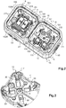
- this second embodiment of the sealed electrical equipment here in a projecting version, comprising the cover 320, 420, 520, 620, 720 and a support frame 300 on which the cover 320 is attached, 420, 520, 620, 720.
- this second embodiment of the sealed electrical equipment could be produced in a built-in version.
- the projecting version of the electrical equipment 1 comprises an electrical box 10 in two parts.
- this electrical box 10 comprises a body 15 which has a generally parallelepipedal shape with cut angles. As a variant, it could have a different shape, for example cylindrical.
- the electrical box 10 shown on figures 1 to 3 is a multi-station box, more precisely here double station, while the one shown in part on the figure 14 is a single post box.
- the body 15 of the electrical box 10 is here made in two distinct main parts: a rear part 12 called “support plate 12” and a front part 17 called “frame 17”, but it could very well be made in a single part.
- the support plate 12 has a bottom wall 11, which forms the bottom wall 11 of the body 15, and a side wall which, assembled with the frame 17, forms the side wall 16 of the body 15.
- the side wall 16 and the bottom wall 11 of the body 15 define a receiving housing adapted to receive the hub cap 120, 220; 320, 420, 520, 620, 720 provided with an apparatus mechanism 110, 210, such as an outlet mechanism 110 or an electrical switch mechanism 210 ( figures 2 and 4 ).
- the bottom wall 11 is designed to be fixed to the wall wall, while the side wall 16 is designed to protect the equipment mechanism 110, 210 and to receive the cover 120, 220; 320, 420, 520, 620, 720.
- the bottom wall 11 of the support plate 12 carries uprights 30 ( figures 1 and 3 ). These uprights 30 extend, inside said receiving housing, forward from the bottom wall 11. They extend perpendicularly thereto.
- the uprights 30 comprise in particular means for mounting a base of the fitting mechanism 110, 210. These mounting means are for example latching means which receive additional latching means 111, 211 provided on the base. of the gear mechanism 110, 210 ( figures 2 and 4 ).
- These mounting means present on the uprights 30 then allow, when mounting the switchgear mechanism 110, 210 in the electrical box 10, to position the base of the switchgear mechanism 110, 210 in the electrical box 10 at a determined distance from the bottom wall 11 of the support plate 12 so as to leave a free space for easily placing the electrical connection wires.
- each fitting mechanism there are provided here four uprights 30 arranged, in pairs, symmetrically with respect to a center O of the bottom wall 11 of the support plate 12.
- the center O of the bottom wall 11 of the support plate 12 is therefore a center of symmetry for the positioning of the uprights 30.
- This central symmetry in the positioning of the uprights 30 of the support plate 12 allows the mounting of the electrical switchgear mechanism 110, 210 in the electrical box 10 in different positions offset from each other by rotation about a z axis ( figure 3 ) orthogonal to the bottom wall 11 of the support plate 12 and passing through the center O of this bottom wall 11.
- the orientation of the electrical box 10 is changed, for example by being rotated 90 degrees to changing from a horizontal to vertical configuration (or vice versa)
- the orientation of the fitting mechanism 110, 210 is also changed accordingly.
- the side wall 16 of the body 15 of the electrical box 10 is cut to receive at least one cable gland 50 for the passage of an electrical cable or an electrical sheath of ICTA type or an IRL tube, intended to supply the connection terminals of the switchgear mechanism 110, 210.
- each opening delimited by the pavement 18 is here of square shape, but it could be of any other shape as long as it is adapted to the shape of the base of the fitting mechanism.
- each hub cap 120, 220 is adapted to be mounted in arrangements of a frame fitting 20, here a multi-station fitting frame, more particularly a double-station fitting frame with horizontal fixing.
- the recessing frame 20 double posts essentially comprises a side wall 26 which internally defines a main opening, divided in two by an internal branch 21 so as to define two reception openings 25 of two hubcaps 120, 220, each provided with 'an equipment mechanism 110, 210.
- Each reception opening 25 has a generally square shape with cut angles. As a variant, it could have a different shape, for example cylindrical, and in any event a shape adapted to the external shape of the cover 120, 220.
- Means are provided at the rear of the fitting frame 20. for mounting to a flush-mounting box (not shown), in particular openings 27 ( figure 4 ) for the passage of a fixing screw intended to be fixed in the flush-mounting box.
- the fitting frame 20 comprises, for the fixing of each hub cap 120, 220, a stop sidewalk 28 projecting inside each reception opening 25 as well as the support frame 200 provided with a peripheral rim delimiting the reception opening 25 of the cover 120, 220.
- the stop sidewalk 28 which runs along the side wall 26 delimiting the reception housing itself defines an opening adapted to the passage of the base of the fitting mechanism 110, 210.
- each opening delimited by the sidewalk 28 is here of square shape, but it could be of any other shape as long as it is adapted to the shape of the base of the mechanism equipment.
- the latter carries, at the rear, uprights 35 ( figure 4 ).
- These uprights 35 extend, inside said receiving housing, rearwardly from a rear face of the sidewalk 28 as an abutment. They extend perpendicular to it.
- the uprights 35 in particular include the means for mounting the base of the fitting mechanism 110, 210.
- These mounting means are for example latching means which receive additional latching means 111, 211 provided on the base of the mechanism. equipment 110, 210.
- each fitting mechanism 110, 210 there are provided here four uprights 35 arranged, in pairs, symmetrically with respect to a center of each receiving opening 25.
- the uprights 35 are arranged opposite the corners in cut angles of each reception opening 25.
- each reception opening 25 is therefore a center of symmetry for the positioning of the uprights 35.
- This central symmetry in the positioning of the uprights 35 makes it possible to authorize the mounting of the electrical equipment mechanism 110, 210 on the frame d. 'embedding 20 in different positions offset from each other by rotation about a z axis ( figure 4 ).
- the orientation of the mounting frame 20 is changed, for example by being rotated by 90 degrees to go from a horizontal to vertical configuration (or vice versa)
- the orientation of the fitting mechanism 110, 210 is changed. also amended accordingly.
- the support frame 100; 200; 300 of the electrical box 10 or of the embedding frame 20 is designed to receive the trim 120, 220; 320, 420, 520, 620, 720.
- the support frame 100; 200; 300 comprises, on an inner face along each reception opening 25, means for receiving complementary to the means for mounting the cover 120, 220; 320, 420, 520, 620, 720.
- the cover 120; 320, 420, 520, 720 comprises, inside a structural part 121; 321, 421, 521, 721 in the form of a frame, an insertion shaft 122 of an electrical plug ( figures 1 , 4 , 5 , 15 , 17 , 20 and 26 ).
- the structural part 121; 321, 421, 521, 721 in the form of a frame has a side portion 126; 326, 426, 526, 726 extending rearwardly from its front face 123; 323, 423, 523, 723 over a predetermined height.
- the hubcap 120 also carries a hinged cover 125 for protecting the insertion slot 122 ( figures 4 and 5 ).
- the cover 220; 620 has a control key 222; 622 ( figures 4 and 23 ) adapted to snap onto receiving means 225 provided on the front face 223 of the structural part 221 in the form of a frame.
- These receiving means 225 are provided to provide the control key 222 with tilting mobility.
- the structural part 221; 621 in the form of a frame has a side portion 226; 626 extending rearwardly from its front face 223; 623 to a predetermined height.
- the structural part 121, 221; 321, 421, 521, 621, 721 in the form of a frame comprises means for mounting the cover 120, 220; 320, 420, 520, 620, 720 on the support frame 100; 200; 300.
- These means for mounting the trim 120, 220; 320, 420, 520, 620, 720 are intended to cooperate with complementary receiving means provided in the peripheral rim of the support frame 100; 200; 300.
- the means for mounting the cover 120, 220; 320, 420, 520, 620, 720 are adapted to cooperate with the additional reception means provided in the support frame 100; 200; 300 in each of two positions of the cover 120, 220; 320, 420, 520, 620, 720 on the support frame 100; 200; 300.
- the two positions are oriented at 90 degrees to each other.
- the second position is obtained by rotating 90 degrees around the z axis ( figure 1 ).
- These two positions correspond for example to an assembly of the electrical equipment in a horizontal configuration ( figures 4 and 11 ) and in a vertical configuration ( figure 13 ).
- this support frame 100; 200 comprises two groups of different receiving means: a first group of receiving means for mounting the cover 120, 220 according to the first position and a second group of receiving means for mounting the cover 120, 220 according to the second position rotated 90 degrees relative to the first position.
- the hub cap 120, 220 comprises only one group of mounting means which will allow it to be mounted on the support frame 100; 200 in the two different positions oriented at 90 degrees relative to each other indifferently.
- This single group of means for mounting the cover 120, 220 will therefore cooperate with one or the other of the groups of means for receiving the support frame 100; 200 (depending on the chosen mounting position).
- the same support frame 100; 200 can be used for both configurations (with means for receiving complementary to the hubcap mounting means adapted to each of the configurations).
- the receiving means provided on a front portion of the peripheral rim of the support frame 100; 200 are here formed by housings 101, 102A, 102B, 103, 104 provided in the four branches of the support frame 100 delimiting the reception opening 14; 25.
- these housings are generally rectangular recesses formed hollow on an internal face of the front portion of the peripheral rim of the support frame 100; 200. They open out towards the inside of the support frame 100; 200, that is to say that they are accessible from the reception opening 14; 25.
- each of the four branches of the support frame 100; 200 comprises at least two housings 101, 102A, 102B, 103, 104. More precisely, each branch of the support frame 100; 200 which defines one side of two reception openings 14; 25 successive, here the internal branch 21, comprises four housings 103, 104 while each branch delimiting one side of a single reception opening comprises two housings 101, 102A, 102B.
- the internal branch 21 comprises two pairs of housings 103, 104: one first pair of housings 103 for mounting a first hub cap 120 in one of the reception openings 14; 25 and a second pair of housings 104 for mounting a second hub cap 220 in the other receiving opening 14; 25, juxtaposed with the first reception opening 14; 25.
- the particular arrangement of the four housings 103, 104, aligned and offset one after the other, in the internal branch 21 makes it possible in particular to reduce the thickness of the internal branch 21 separating two reception openings 14; 25 successive.
- Each group of receiving means associated with a mounting position of the cover 120, 220 is here formed by four housings 101, 102A, 102B, 103, 104 located in the opposite branches of the support frame 100; 200 delimiting the reception opening 14; 25.
- the means for receiving the group associated with the first mounting position of the cover 120, 220 are for example formed by the two housings 102A and the two housings 104 of the internal branch 21.
- the means for receiving the group associated with the first mounting position of the cover 120, 220 are for example formed by the two housings 102B and the two housings 103 of the internal branch 21.
- the means for receiving the group associated with the second position are formed by the two housings 101 of the opposite branches of the support frame 100; 200 (visible only on one of the two branches on the figures 1 and 4 ).
- the hubcap mounting means 120, 220 are here quarter-turn tabs 128 movable in rotation by a quarter-turn between an unlocked position and a locked position and accessible by the front face 123, 223 of the hubcap 120, 220 through a maneuver window 129A.
- quarter-turn tabs 128 are housed in dedicated housings 127, 227 of the lateral part 126, 226 of the cover 120, 220. These housings 127, 227 open outwards from the cover 120, 220 and are intended for to be placed in correspondence with the housings 101, 102A, 102B, 103, 104 of the support frame 100; 200. Each housing 127, 227 has an internal shape making it possible to fully accommodate the associated quarter-turn tab in the unlocked position and allowing the latter to be pivoted by a quarter-turn to its locked position (in which a portion of the quarter-turn tab protrudes from the housing 127, 227 concerned).
- Four quarter-turn tabs 128 are provided here, two per opposite side of the lateral part 126, 226 of the cover 120, 220.
- each quarter-turn tab 128 is movable between the unlocked position and the locked position so as to allow the mounting of the cover 120, 220 on the support frame 100; 200 and lock it onto it.
- each quarter-turn tab 128 is movable in rotation by a quarter-turn around the z axis orthogonal to the front face 123, 223 of the cover 120, 220 ( figure 5 ).
- all the quarter-turn tabs 128 are movable in rotation in the same predefined direction from the locked position to reach the unlocked position (and by symmetry in the same other predefined direction from the unlocked position to reach the locked position).
- each quarter-turn tab 128 In the unlocked position, each quarter-turn tab 128 is fully housed in the associated housing 127, 227 ( figures 7 and 8 ). In the locked position, a portion of each quarter-turn tab 128 projects from the associated housing 127, 227 ( figure 9 ) and is housed in the corresponding housing 101, 102A, 102B, 103, 104 of the support frame 100; 200.
- each quarter-turn tab 128 has an elongated shape.
- Each quarter-turn tab 128 includes two parts: an operating part 128A and a locking part 128B.
- the operating part 128A comprises an arcuate edge positioned against an arcuate part of the corresponding housing 127, 227 and a cylindrical pad 128C projecting from the front face of the quarter-turn tab 128 placed in correspondence with the maneuver window 129A so as to allow pivoting of the quarter-turn tab 128.
- Each maneuver window 129A has a complementary shape to the cylindrical pad 128C of the associated quarter-turn tab 128 ( figures 5, 6 , 8 and 9 ).
- the cylindrical 128C stud is provided with a 128D maneuver notch accessible through the 129A maneuver window.
- the tip of a tool such as a screwdriver is introduced, through the operating window 129A, into this operating notch 128D in order to rotate the quarter-turn tab 128 between its unlocked and locked positions (and vice versa).
- each maneuvering notch 128D extends in the plane of the front face 123, 223 of the cover 120, 220 along the Y axis.
- the maneuvering notch 128D extends in the plane of the front face 123, 223 of the cover along the X axis.
- each quarter-turn tab 128 forms, on its end opposite the end of the arc of a circle of the operating part 128A, a stop rim 128E.
- This stop rim 128E has a right angle shape.
- Each stop rim 128E is designed to, in the locked position of the quarter-turn tab 128, come into abutment with a stop rim 22A of the support frame 100; 200 (described below, see figures 11 to 13 ).
- the end of the locking portion 128B along the stop rim 128E is intended to be housed in the housing 101, 102A, 102B, 103, 104 associated with the support frame 100; 200.
- This housing 101, 102A, 102B, 103, 104 associated is placed opposite the housing 127, 227 corresponding to the side wall 126, 226 of the cover 120, 220 in which is housed the quarter turn tongue 128 concerned.
- each quarter-turn tab 128 also comprises, on its front face, a portion 128F projecting from this front face.
- This portion 128F forms a boss on the front face of the locking part 128B of each quarter-turn tab 128.
- This boss is adapted to be placed in correspondence with an internal protuberance 123A, 223A associated with the cover 120, 220 (introduced below) when moving the quarter-turn tab 128 between its unlocked and locked positions. It also serves as a stopper in the unlocked position and in the locked position of the quarter-turn tab 128.
- each locking window 129B is placed at a predetermined distance from the maneuvering window 129A associated with it.
- This locking window 129B has a shape complementary to the portion 128F projecting from each quarter-turn tab 128.
- the portion 128F projecting from the front face of the quarter-turn tab 128 is visible from the front of the trim 120, 220 (and therefore from the front of the electrical equipment 1; 5) .
- the portion 128F projecting from the front face of the quarter-turn tab 128 is not introduced into the locking window 129B (this window is therefore empty).
- the locking window 129B therefore acts as a window indicating the locking of the trim 120, 220 on the support frame 100; 200.
- each housing 127, 227 of the side wall 126, 226 of the cover 120, 220 comprises the internal protuberance 123A, 223A.
- This internal protuberance 123A, 223A is positioned opposite the quarter-turn tab 128.
- This internal protuberance 123A, 223A forms the passage of a hard point for the portion 128F projecting from the associated quarter-turn tab 128 when the latter. is moved between its unlocked and locked positions.
- This internal protuberance 123A, 223A is then deformed by the portion 128F projecting from each quarter-turn tab 128 so that the quarter-turn tab 128 is moved between its unlocked and locked positions.
- the internal protuberance 123A, 223A therefore makes it possible to index the locked position during the locking of the cover 120, 220 on the support frame 100; 200.
- the two pairs of housings 103, 104 of the internal branch 21 of the support frame 100; 200 are offset so as to be aligned along the inner leg 21.
- this offset allows a staggered arrangement of the quarter-turn tabs 128 when they are in the locked position in this internal branch 21.
- a wall 22 separating two juxtaposed housings 103 and 104 forms the stop rim 22A of the support frame 100; 200 for the stop rim 128E of the locking portion 128B of the quarter-turn tab 128 when the latter is in the locked position.
- a wall 22 forms two abutment flanges 22A for two quarter-turn tabs 128 arranged in staggered rows.
- the support frame 300 comprises a single group of receiving means cooperating with the single group of means for mounting the cover 320, 420, 520, 620, 720 in two positions oriented at 90 degrees with respect to one another. other.
- a single group of receiving means in the support frame 300 allows the mounting of the cover 320, 420, 520, 620, 720 according to the two different positions oriented at 90 degrees one of the other.
- the receiving means provided on a front portion of the peripheral rim of the support frame 300 are here formed by housings 301 provided in the corners of the support frame 300. More particularly, the housings 301 are provided in the cut corner parts of the support frame 300 positioned at the four corners of the opening reception 36 of the hubcap 320, 420, 520, 620, 720 in the electrical box ( figure 14 ) or the mounting frame (not shown for this second embodiment).
- these housings 301 are generally rectangular recesses formed hollow in these cut corner parts of the support frame 301.
- hubcaps 320, 420, 520, 620, 720 of the electrical equipment will be described, each of which comprises suitable mounting means to cooperate with the housings 301 of the support frame 300.
- the means for mounting the cover 320, 420, 520, 620 are movable elements 328, 428, 528, 628 in translation, in a plane parallel to a mean plane of the cover 320, 420, 520, 620, between a retracted position and an extended position.
- the extended position of the movable elements 328, 428, 528, 628 corresponds to the locking of the cover 320, 420, 520, 620 in the housings 301 of the support frame 300.
- These movable elements 328, 428, 528, 628 are for example made of metal. .
- each pair of movable elements 328, 428, 628 is here intended to cooperate with two of the housings 301 of the support frame 300 (therefore a movable element 328, 428, 628 cooperates with a corresponding housing 301).
- the two pairs of movable elements 328, 428, 628 are positioned in opposite sides of the side wall 326, 426, 626 of the cover 320, 420, 620. As shown in the figures. figures 15 to 19 and 23 to 25 , the movable elements 328, 428, 628 of each pair are positioned symmetrically in the housings provided in the side wall 326, 426, 626.
- each movable element 328, 428, 628 has the shape of an arm.
- the arm of each movable element 328, 428, 628 comprises a free end 328A, 428A, 628A truncated in a shape complementary to the cut angle portion in which the housing 301 is formed constituting the associated receiving means in the support frame 300.
- This free end of the arm of each movable element 328, 428, 628 is therefore intended to cooperate with the corresponding housing 301 of the support frame 300.
- the opposite end 328B, 428B, 628B of each movable element 328, 428, 628 is shaped to correspond to the actuator used to move this movable element 328, 428, 628.
- each movable element 328, 628 is driven by an actuator 329 movable in translation so as to move this movable element 328, 628 from its retracted position to its extended position, that is to say to position it in the position allowing the locking the cover 320, 620 on the support frame 300.
- the actuator 329 is configured to move the movable elements 328, 628 of each pair away from each other.
- the actuator 329 is a member in the form of a fish plate.
- This actuator 329 is introduced, from the front, in a direction orthogonal to the mean plane of the cover 320, in an orifice 329A provided at the front on the support frame 300 in order to act on each movable element 328 to move this last between its retracted position and its extended position.
- a single actuator 329 is adapted to simultaneously move the two movable elements 328 of each pair and separate them from one another.
- the actuator 329 when the actuator 329 is introduced into the orifice 329A, the displacement from the front to the rear, perpendicular to the mean plane of the cover 320, of this actuator 329 causes a displacement of each movable element 328, in translation in a direction transverse to the direction of movement of the actuator 329 (and parallel to the mean plane of the cover 320).
- the opposite end 328B of the movable element 328 comprises an elastic return element formed by a leaf spring 328C.
- This leaf spring 328C acts permanently on each movable element 328 to return it to the retracted position.
- the actuator 329 acts, inside the frame-shaped structural part 321 of the cover 320, against each leaf spring 328C of the movable elements 328.
- each movable element 328 of each pair is therefore returned to its retracted position.
- each movable member 628 includes a maneuvering portion 628C designed to cooperate with the end of a maneuvering tool to allow a user to move each movable member 628 in translation.
- Each maneuvering portion 628C has a generally rectangular shape.
- each maneuvering part 628C includes a maneuvering window 628D.
- This maneuver window 628D here has a rectangular shape.
- This maneuvering window 628D is designed to receive the tip of a maneuvering tool such as a screwdriver to move each movable element 628 from its retracted position to its extended position (and vice versa).
- the front face of the cover 623 comprises windows 629 from which each maneuvering part 628C of each movable element 628 emerge.
- These windows 629 here have a rectangular shape similar to that of the parts. 628C maneuvering part but a length greater than that of the associated 628C maneuvering part.
- the length of each window 629 corresponds to the amplitude of displacement necessary to move each movable element 628 from its retracted position to its extended position.
- a maneuvering tool such as a screwdriver used from the front of the cover 620 allows each movable element 628 to be moved independently in order to move it between its retracted position and its extended position so as to lock the cover 620 on the frame. support 300 and to move it between its extended position and its retracted position so as to unlock the cover 620 of the support frame 300.
- each movable member 428 includes, on its front face, a notch 428C extending transversely to the direction of the elongated shape of the movable member 428.
- Each notch 428C is designed to receive and cooperate with a projecting portion 429C of a movable actuator 429 causing the translational movement of the movable element 428 concerned.
- each movable element 428 is driven by the movable actuator 429 in rotation so as to bring this movable element 428 from its retracted position to its extended position, that is to say to bring it into the position allowing the locking. of the trim 420 on the support frame 300.
- the actuator 429 is a quarter-turn element of generally cylindrical shape.
- An actuator 429 is designed to act on a pair of movable elements 428 (the two movable elements 428 of each pair are therefore moved simultaneously by the associated actuator 429). Two mobile actuators 429 are thus provided here.
- each actuator 429 is in the form of a pin comprising an operating head 429A and a cylindrical body 429B.
- the maneuvering head 429A of each actuator 429 is accessible from the front face of the cover 420.
- the maneuvering head 429A of each actuator 429 comprises a maneuvering notch 429D of rectangular shape intended to receive the tip of a cutting tool. maneuver such as a screwdriver so that a user rotates actuator 429.
- the cylindrical body 429B of the actuator 429 comprises two protruding parts 429C.
- Each of the two protruding parts 429C is designed to cooperate with a notch 428C of the movable element 428.
- each protrusion 429C is engaged in the notch 428C of the associated movable member 428 in order to move the latter.
- the rotational movement of the actuator 429 is transformed, thanks to the cooperation of each projecting part 429C of the actuator 429 with the notch 428C of the movable element 428, into a translational movement of each element movable 428.
- each movable element 428 when the actuator 429 is actuated in rotation in one direction by a user, for example clockwise, each movable element 428 is moved from its retracted position to its extended position (then corresponding to the locking of the hub cap 420 on the support frame 300).
- each movable element 428 is moved from its extended position to its retracted position.
- each movable element 528 having a U-shape.
- the U-shape of each movable element 528 consists of two side branches 528A and a central branch 528B.
- the junction part between each side branch 528A and the central branch 528B is a cut angle portion 527 intended to cooperate with a housing 301 of the support frame 300.
- each cut angle portion 527 comprises a protuberance provided with a stop rim 527A intended to come into abutment with a part of the associated housing 301 of the support frame 300 when locking the cover 520 on the support frame 300.
- each U-shaped movable element is here intended to cooperate with two housings 301 of the support frame 300.
- a single movable element 528 is used for locking a full side of the cover 520 on the frame. support 300. This makes it possible, for example, to reinforce the locking of the cover 520 on the support frame 300.
- each U-shaped movable element 528 is positioned in a corresponding housing formed in the side wall 526 of the cover 520.
- the two movable elements 528 are here positioned symmetrically opposite in the corresponding housings of the side wall 526 of the hubcap 520 so that the two central branches 528B of the two movable elements 528 are parallel and the side branches 528A are aligned in pairs.
- the set of two movable elements 528 thus positioned therefore form a frame.
- the side branches 528A of one of the two movable elements 528 are connected to the side branches 528A of the other of the two movable elements 528 by a thrust spring 528C. More precisely, two thrust springs 528C make the connection between the branches 528A of each movable element 528. Each thrust spring 528C is here shown in a compressed stable state.
- the combination of the two movable elements 528 and of the two thrust springs 528C therefore forms a single frame-shaped element.
- the state of the thrust springs 528C is then associated with the position (retracted or extended) of the movable element 528.
- the thrust springs are in their compressed stable state, the movable members 528 are in the retracted position.
- the two push springs 528C are in a relaxed stressed state, the two movable elements 528 are in the extended position.
- each branch 528B of each movable element 528 comprises a central part 528D projecting towards the inside of the cover 520 ( figures 21 and 22 ).
- Each central part 528D includes a maneuvering window 528E.
- Each 528E maneuver window has a generally rectangular shape with an off-hook portion 528F positioned at an interior end of the 528E maneuver window ( figure 22 ).
- each maneuvering window 528E is intended to receive a movable actuator 529 designed to allow the translational movement of each movable element 528.
- each movable element 528 is driven by the movable actuator 529 in rotation so as to bring this movable element 528 from its retracted position to its extended position (allowing the locking of the cover 520 on the support frame 300).
- two mobile actuators 529 are provided here.
- Each actuator 529 is here a quarter-turn element having a generally cylindrical operating head 529A and a locking part 529B intended to cooperate with the part 528F unhooked from the operating window 528E of the central part 528D of the branch 528B of the 'associated movable element 528.
- the maneuvering head 529A of each actuator 529 comprises a maneuvering notch 529D of rectangular shape intended to receive the tip of an operating tool such as a screwdriver in order to move in rotation the actuator 529.
- each actuator 529 is accessible from the front face of the trim 520.
- each actuator 529 includes a right angled portion 529C with two abutment flanges and an arcuate portion.
- the right-angled part 529C is designed to cooperate with the part 528F unhooked from the maneuvering window 528E of the central part 528D of the branch 528B of the movable element 528 associated.
- the positioning of the locking portion 529B of each actuator 529 in the maneuvering window 528E has an impact on the state of the thrust spring 528C and therefore on the locking of the movable element 528 on the support frame 300.
- the locking part 529B of the actuator 529 comes into abutment with the maneuvering window 528E (without cooperating with the part 528F when unhooked from the maneuvering window 528E of the central part 528D of the branch 528B of the associated movable element).
- the push springs 528C which are moved simultaneously, are returned to their compressed stable state and held in this position by the stop of the locking part 529B of the actuator 529 in the operating window 528E.
- the locking part 529B of the actuator 529 comes into abutment with the part 528F unhooked from the maneuvering window 528E of the part. center 528D of the branch 528B of the associated movable element and cooperates exactly therewith (see the movable element 528 on the left on the figure 22 ).
- the push springs 528C are brought into a relaxed prestressed state.
- the rotation of the actuator 529 in the clockwise direction forces the thrust springs 528C from their compressed rest state to the relaxed prestressed state.
- each portion 527 of the movable element 528 set in motion cooperates with the associated housing 301 of the support frame 300.
- This movable element 528 is therefore in the extended position and the cover 520 is locked on the support frame 300 (on this side).
- the mounting of the cover 520 on the support frame 300 is carried out for each movable element 528 successively.
- the thrust springs 528C relax but still retain a compressive stress due to the other movable element 528 which is itself still in the retracted position (and as indicated previously each push spring 528C constantly tends to return to its compressed stable state).
- the push springs 528C are therefore effectively at rest only when the two movable elements 528 are both in the extended position.
- the hubcap mounting means 720 are movable elements 728 to rotate between an unlocked position and a locked position.
- the hubcap mounting means 720 are movable elements 728 to rotate between an unlocked position and a locked position.
- Each movable element 728 is intended to cooperate with a housing 301 of the support frame 300.
- each movable element 728 is here a quarter-turn element.
- Each movable element 728 is movable between an unlocked position and a locked position so as to allow the mounting of the cover 720 on the support frame 300 and to lock it thereon.
- each movable element 728 is movable in rotation about the z axis orthogonal to the front face 723 of the cover 720 ( figure 26 ).
- all the movable elements 728 are movable in rotation in the same predefined direction, for example here the counterclockwise direction, from the locked position to reach the unlocked position (and by symmetry in another same predefined direction, for example here the clockwise direction, from the unlocked position to reach the locked position).
- each movable element 728 has an L-shape in two parts: an operating part 728A and a locking part 728B.
- the maneuvering part 728A has an elongated shape (corresponding to the vertical part of the "L") while the locking part 728B extends generally perpendicular to the maneuvering part 728A.
- each operating part 728A has on its front face an operating notch 728C intended to allow the displacement of the movable element 728 associated in rotation between its unlocked and locked positions (and vice versa), for example thanks to the introduction of a tool such as a screwdriver through an operating window 729A.
- Each maneuvering notch 728C therefore acts as a pivot for the associated movable element 728.
- Each maneuvering notch 728C is accessible via the maneuvering window 729A formed on the front face of the structural part 721 in the form of a frame of the cover 720 ( figure 26 ).
- Each maneuvering window 729A here has a generally cylindrical shape.
- the locking part 728B is intended to come into abutment against a wall of a housing 729 associated with the side wall 726 of the structural part 721 in the form of a frame of the cover 720 when the movable element 728 is in the unlocked position.
- the angle formed between the operating part 728A and the locking part 728B of each movable element, for its part, comes into abutment with a wall of the housing 301 of the support frame 300 ( figure 27 ).
- the mounting of the cover 120, 220; 320, 420, 520, 620, 720 on the support frame 100; 200; 300 of the electrical equipment 1; 5 is produced by bringing the means for mounting the cover 120, 220; 320, 420, 520, 620, 720 to cooperate with the means for receiving the support frame 100; 200; 300 for example by bringing each mounting means from its unlocked position to its locked position or from its retracted position to its extended position.
- the mounting of the hub cap 120, 220; 320, 420, 520, 620, 720 is carried out initially according to a first configuration (for example horizontal).
- the hubcap is then mounted on the support frame 100; 200; 300 placed in its new position thanks to the cooperation of the hub cap mounting means 120, 220; 320, 420, 520, 620, 720 to cooperate with the means for receiving the support frame 100; 200; 300.
Landscapes
- Engineering & Computer Science (AREA)
- Architecture (AREA)
- Civil Engineering (AREA)
- Structural Engineering (AREA)
- Casings For Electric Apparatus (AREA)
- Motor Or Generator Frames (AREA)
Priority Applications (1)
| Application Number | Priority Date | Filing Date | Title |
|---|---|---|---|
| EP23189796.8A EP4258499A3 (de) | 2019-12-20 | 2020-12-03 | Abgedichtetes elektrisches gerät |
Applications Claiming Priority (1)
| Application Number | Priority Date | Filing Date | Title |
|---|---|---|---|
| FR1915140A FR3105624B1 (fr) | 2019-12-20 | 2019-12-20 | Appareillage électrique étanche |
Related Child Applications (1)
| Application Number | Title | Priority Date | Filing Date |
|---|---|---|---|
| EP23189796.8A Division EP4258499A3 (de) | 2019-12-20 | 2020-12-03 | Abgedichtetes elektrisches gerät |
Publications (1)
| Publication Number | Publication Date |
|---|---|
| EP3840154A1 true EP3840154A1 (de) | 2021-06-23 |
Family
ID=70918509
Family Applications (2)
| Application Number | Title | Priority Date | Filing Date |
|---|---|---|---|
| EP23189796.8A Pending EP4258499A3 (de) | 2019-12-20 | 2020-12-03 | Abgedichtetes elektrisches gerät |
| EP20211640.6A Pending EP3840154A1 (de) | 2019-12-20 | 2020-12-03 | Wasserdichtes elektrogerät |
Family Applications Before (1)
| Application Number | Title | Priority Date | Filing Date |
|---|---|---|---|
| EP23189796.8A Pending EP4258499A3 (de) | 2019-12-20 | 2020-12-03 | Abgedichtetes elektrisches gerät |
Country Status (2)
| Country | Link |
|---|---|
| EP (2) | EP4258499A3 (de) |
| FR (1) | FR3105624B1 (de) |
Citations (5)
| Publication number | Priority date | Publication date | Assignee | Title |
|---|---|---|---|---|
| DE29803339U1 (de) * | 1998-02-25 | 1998-05-07 | Albrecht Jung GmbH & Co KG, 58579 Schalksmühle | Zwischenrahmen für ein elektrisches Installationsgerät |
| DE102004024093A1 (de) * | 2004-05-14 | 2005-12-08 | Berker Gmbh & Co. Kg | Abdeckung |
| DE102005052794A1 (de) * | 2005-11-05 | 2007-05-10 | Abb Patent Gmbh | Halteelement zur Befestigung eines Abdeckrahmens eines Installationsgerätes |
| EP1860748A1 (de) | 2006-05-22 | 2007-11-28 | Legrand France | Teilbares elektrisches Gerät zur überstehenden Anordnung oder zum Einbau in eine Wand |
| EP3091549A1 (de) * | 2015-05-07 | 2016-11-09 | Abb Ag | Installationsgerät der haus- oder gebäudeinstallationstechnik mit erweiterter funktionalität |
-
2019
- 2019-12-20 FR FR1915140A patent/FR3105624B1/fr active Active
-
2020
- 2020-12-03 EP EP23189796.8A patent/EP4258499A3/de active Pending
- 2020-12-03 EP EP20211640.6A patent/EP3840154A1/de active Pending
Patent Citations (5)
| Publication number | Priority date | Publication date | Assignee | Title |
|---|---|---|---|---|
| DE29803339U1 (de) * | 1998-02-25 | 1998-05-07 | Albrecht Jung GmbH & Co KG, 58579 Schalksmühle | Zwischenrahmen für ein elektrisches Installationsgerät |
| DE102004024093A1 (de) * | 2004-05-14 | 2005-12-08 | Berker Gmbh & Co. Kg | Abdeckung |
| DE102005052794A1 (de) * | 2005-11-05 | 2007-05-10 | Abb Patent Gmbh | Halteelement zur Befestigung eines Abdeckrahmens eines Installationsgerätes |
| EP1860748A1 (de) | 2006-05-22 | 2007-11-28 | Legrand France | Teilbares elektrisches Gerät zur überstehenden Anordnung oder zum Einbau in eine Wand |
| EP3091549A1 (de) * | 2015-05-07 | 2016-11-09 | Abb Ag | Installationsgerät der haus- oder gebäudeinstallationstechnik mit erweiterter funktionalität |
Non-Patent Citations (1)
| Title |
|---|
| LEGRAND: "Plexo IP55", 15 July 2014 (2014-07-15), XP055725460, Retrieved from the Internet <URL:https://www.tim.pl/fileuploader/download/download/?d=1&file=GLOWNA/1131/111/AA/FA1/08/karta_069679.pdf> [retrieved on 20200826] * |
Also Published As
| Publication number | Publication date |
|---|---|
| EP4258499A2 (de) | 2023-10-11 |
| FR3105624A1 (fr) | 2021-06-25 |
| FR3105624B1 (fr) | 2022-01-07 |
| EP4258499A3 (de) | 2023-12-20 |
Similar Documents
| Publication | Publication Date | Title |
|---|---|---|
| EP0612090B1 (de) | Drehbetätigungseinrichtung für einen Leistungsschalter | |
| EP2456024B1 (de) | Stromsteckdose mit Verschlussvorrichtung | |
| EP2936634B1 (de) | Elektrisches ausrüstungsmodul | |
| FR3054925A1 (fr) | Module de commande pour appareil de coupure electrique modulaire et appareil de coupure electrique modulaire obtenu | |
| EP3172750B1 (de) | Verkleidung für elektrischen schalter und elektrischer schalter mit solch einer verkleidung | |
| EP3138166B1 (de) | Elektromodul zum einschnappen in eine elektrodose | |
| EP3072194A1 (de) | Schaltanlagenhalterung mit einem verbindungsinstrument zur befestigung davon an einer wanddose, zugehöriges verbindungsinstrument, verbindungsanordnung und elektrische schaltanlage | |
| EP2456021B1 (de) | Stromsteckdose mit seitlichen verschiebbaren Balken | |
| EP1318569B1 (de) | Elektrischer Steckanschluss mit Verschlussbuchsenblenden und Baureihe mit einem solchen Steckanschluss | |
| WO2015118241A1 (fr) | Appareillage électrique a encastrer | |
| EP3840154A1 (de) | Wasserdichtes elektrogerät | |
| EP3255732B1 (de) | Elektrische verbindungsklemme, die einen verbindungshebel umfasst, und entsprechende elektrische geräte | |
| FR2622734A1 (fr) | Boitier pour appareil de coupure, notamment disjoncteur ou interrupteur, utilisable en atmosphere explosible | |
| EP1376772B1 (de) | Elektrischer Steckanschluss mit Verschlussbuchsenblenden und Baureihe mit einem solchen Steckanschluss | |
| EP3840151A1 (de) | Elektrische anschlussdose und entsprechendes elektrisches gerät | |
| EP1978610A1 (de) | Steckdose mit doppelter Stromversorgungskonfiguration | |
| CA2932321C (fr) | Dispositif de coupure electrique pour batterie d'accumulateurs | |
| EP0401097A1 (de) | Vorrichtung zum Verriegeln einer Verbindung | |
| WO2019020897A1 (fr) | Bloc multi-appareillages avec élément d'appui anti porte-à-faux | |
| EP2068411A1 (de) | Elektrische Einbau-Ausrüstung mit Schnellanschluss | |
| EP1126486A1 (de) | Mehrpoliger Schalter | |
| EP2442337B1 (de) | Schlüsselkontaktvorrichtung | |
| EP2936635A1 (de) | Elektrisches ausrüstungsmodul | |
| WO2021122051A1 (fr) | Appareillage electrique | |
| FR2701592A1 (fr) | Dispositif de commande rotative d'un disjoncteur. |
Legal Events
| Date | Code | Title | Description |
|---|---|---|---|
| PUAI | Public reference made under article 153(3) epc to a published international application that has entered the european phase |
Free format text: ORIGINAL CODE: 0009012 |
|
| STAA | Information on the status of an ep patent application or granted ep patent |
Free format text: STATUS: THE APPLICATION HAS BEEN PUBLISHED |
|
| AK | Designated contracting states |
Kind code of ref document: A1 Designated state(s): AL AT BE BG CH CY CZ DE DK EE ES FI FR GB GR HR HU IE IS IT LI LT LU LV MC MK MT NL NO PL PT RO RS SE SI SK SM TR |
|
| STAA | Information on the status of an ep patent application or granted ep patent |
Free format text: STATUS: REQUEST FOR EXAMINATION WAS MADE |
|
| 17P | Request for examination filed |
Effective date: 20210818 |
|
| RBV | Designated contracting states (corrected) |
Designated state(s): AL AT BE BG CH CY CZ DE DK EE ES FI FR GB GR HR HU IE IS IT LI LT LU LV MC MK MT NL NO PL PT RO RS SE SI SK SM TR |
|
| STAA | Information on the status of an ep patent application or granted ep patent |
Free format text: STATUS: EXAMINATION IS IN PROGRESS |
|
| 17Q | First examination report despatched |
Effective date: 20230109 |