EP3783391A1 - Wind field information measurement method and engine room-type laser radar - Google Patents
Wind field information measurement method and engine room-type laser radar Download PDFInfo
- Publication number
- EP3783391A1 EP3783391A1 EP18942353.6A EP18942353A EP3783391A1 EP 3783391 A1 EP3783391 A1 EP 3783391A1 EP 18942353 A EP18942353 A EP 18942353A EP 3783391 A1 EP3783391 A1 EP 3783391A1
- Authority
- EP
- European Patent Office
- Prior art keywords
- signal
- light signal
- frequency
- return light
- processing device
- Prior art date
- Legal status (The legal status is an assumption and is not a legal conclusion. Google has not performed a legal analysis and makes no representation as to the accuracy of the status listed.)
- Withdrawn
Links
- 238000000691 measurement method Methods 0.000 title claims abstract description 10
- 238000012545 processing Methods 0.000 claims abstract description 92
- 238000000034 method Methods 0.000 claims abstract description 35
- 239000000443 aerosol Substances 0.000 claims abstract description 26
- 238000001228 spectrum Methods 0.000 claims description 38
- 238000005070 sampling Methods 0.000 claims description 29
- 230000003287 optical effect Effects 0.000 claims description 28
- 238000010009 beating Methods 0.000 claims description 8
- 238000001914 filtration Methods 0.000 claims description 4
- 238000005259 measurement Methods 0.000 abstract description 12
- 238000010248 power generation Methods 0.000 abstract description 4
- 230000008569 process Effects 0.000 description 13
- 238000010586 diagram Methods 0.000 description 9
- 230000005540 biological transmission Effects 0.000 description 8
- 238000006243 chemical reaction Methods 0.000 description 3
- 238000009434 installation Methods 0.000 description 3
- 238000001514 detection method Methods 0.000 description 2
- 238000012986 modification Methods 0.000 description 2
- 230000004048 modification Effects 0.000 description 2
- 238000009825 accumulation Methods 0.000 description 1
- 230000009286 beneficial effect Effects 0.000 description 1
- 238000004891 communication Methods 0.000 description 1
- 238000012937 correction Methods 0.000 description 1
- 230000007812 deficiency Effects 0.000 description 1
- 230000006872 improvement Effects 0.000 description 1
- 230000010287 polarization Effects 0.000 description 1
- 230000009467 reduction Effects 0.000 description 1
- 230000008054 signal transmission Effects 0.000 description 1
Images


Classifications
-
- G—PHYSICS
- G01—MEASURING; TESTING
- G01S—RADIO DIRECTION-FINDING; RADIO NAVIGATION; DETERMINING DISTANCE OR VELOCITY BY USE OF RADIO WAVES; LOCATING OR PRESENCE-DETECTING BY USE OF THE REFLECTION OR RERADIATION OF RADIO WAVES; ANALOGOUS ARRANGEMENTS USING OTHER WAVES
- G01S17/00—Systems using the reflection or reradiation of electromagnetic waves other than radio waves, e.g. lidar systems
- G01S17/02—Systems using the reflection of electromagnetic waves other than radio waves
- G01S17/50—Systems of measurement based on relative movement of target
- G01S17/58—Velocity or trajectory determination systems; Sense-of-movement determination systems
-
- G—PHYSICS
- G01—MEASURING; TESTING
- G01S—RADIO DIRECTION-FINDING; RADIO NAVIGATION; DETERMINING DISTANCE OR VELOCITY BY USE OF RADIO WAVES; LOCATING OR PRESENCE-DETECTING BY USE OF THE REFLECTION OR RERADIATION OF RADIO WAVES; ANALOGOUS ARRANGEMENTS USING OTHER WAVES
- G01S17/00—Systems using the reflection or reradiation of electromagnetic waves other than radio waves, e.g. lidar systems
- G01S17/88—Lidar systems specially adapted for specific applications
- G01S17/95—Lidar systems specially adapted for specific applications for meteorological use
-
- G—PHYSICS
- G01—MEASURING; TESTING
- G01S—RADIO DIRECTION-FINDING; RADIO NAVIGATION; DETERMINING DISTANCE OR VELOCITY BY USE OF RADIO WAVES; LOCATING OR PRESENCE-DETECTING BY USE OF THE REFLECTION OR RERADIATION OF RADIO WAVES; ANALOGOUS ARRANGEMENTS USING OTHER WAVES
- G01S17/00—Systems using the reflection or reradiation of electromagnetic waves other than radio waves, e.g. lidar systems
- G01S17/02—Systems using the reflection of electromagnetic waves other than radio waves
- G01S17/06—Systems determining position data of a target
- G01S17/08—Systems determining position data of a target for measuring distance only
- G01S17/10—Systems determining position data of a target for measuring distance only using transmission of interrupted, pulse-modulated waves
- G01S17/18—Systems determining position data of a target for measuring distance only using transmission of interrupted, pulse-modulated waves wherein range gates are used
-
- Y—GENERAL TAGGING OF NEW TECHNOLOGICAL DEVELOPMENTS; GENERAL TAGGING OF CROSS-SECTIONAL TECHNOLOGIES SPANNING OVER SEVERAL SECTIONS OF THE IPC; TECHNICAL SUBJECTS COVERED BY FORMER USPC CROSS-REFERENCE ART COLLECTIONS [XRACs] AND DIGESTS
- Y02—TECHNOLOGIES OR APPLICATIONS FOR MITIGATION OR ADAPTATION AGAINST CLIMATE CHANGE
- Y02A—TECHNOLOGIES FOR ADAPTATION TO CLIMATE CHANGE
- Y02A90/00—Technologies having an indirect contribution to adaptation to climate change
- Y02A90/10—Information and communication technologies [ICT] supporting adaptation to climate change, e.g. for weather forecasting or climate simulation
Definitions
- the present disclosure relates to the technical field of wind power generation, and in particular, to a wind field information measurement method and a nacelle-based lidar.
- wind field information is measured by using a nacelle-based lidar mounted on a wind turbine.
- the nacelle-based lidar has the advantages of long detection range and small interference from wind turbine wakes, so it can detect information of the wind field right in front of the wind turbine and provide a basis for load reduction and yaw correction of the wind turbine, thereby achieving the maximum operating efficiency of the wind turbine and increasing power generation capacity.
- a lidar periodically and alternately emits two beams at a fixed frequency, so as to periodically transmit two light signals for detection of the wind field information.
- the wind field information continuously varies and great changes may occur in the wind velocity, wind direction, or the like. Due to the transmission time interval between the two light signals, the wind field information in the time interval cannot be detected; therefore, the wind field information obtained in this manner is inaccurate.
- the present disclosure provides a wind field information measurement method and a nacelle-based lidar.
- a wind field information measurement method is provided and applied in a nacelle-based lidar
- the nacelle-based lidar is mounted on a wind turbine and comprises a multi-wavelength laser, a beam splitter, a frequency modulator, a beam combiner, and a signal processing device
- the multi-wavelength laser is connected to the beam splitter
- the beam splitter is connected to the frequency modulator
- the frequency modulator is connected to the signal processing device
- the beam combiner is connected to the signal processing device
- the wind field information is measured by simultaneously transmitting at least two light signals of different wavelengths, so that the wind field information can be measured in real time, thereby avoiding the problem in the prior art that because two light signals are periodically and alternately transmitted for measurement of the wind field information, the wind field information in the transmission time interval cannot be measured, resulting in inaccurate measurement of the wind field information.
- the obtaining, by the signal processing device, wind field information based on the return light signal comprises: calculating, by the signal processing device, a power spectrum of the return light signal; and obtaining, by the signal processing device, the wind field information according to the power spectrum of the return light signal.
- the power spectrum of the return light signal carries corresponding wind field information, it can be more convenient to obtain the wind field information according to the power spectrum of the return light signal.
- the wind velocity and the wind direction in the wind field information can be obtained through vector operation according to the information carried in the first return light signal and the second return light signal, and thereby more accurate information of the wind field in front of the wind turbine can be obtained.
- the pulse generator generates the pulse signals, and the frequency modulator performs frequency modulation on the first light signal and the second light signal based on the pulse signals, so that the frequency modulator does not need to generate pulse signals for the frequency modulation on the light signals, thereby reducing the data processing load of the frequency modulator.
- ⁇ f 1 differs from ⁇ f 2 by a preset frequency value.
- the beating of the return light signal with the light signal by the coupler facilitates subsequent optical-to-electrical conversion of the return light signal.
- the signal processing device further comprises a sampler, the sampler being connected to the coupler and the signal processor; before the obtaining, by the signal processing device, wind field information based on the return light signal, the method further comprises:
- a nacelle-based lidar which is mounted on a wind turbine and comprises a multi-wavelength laser, a beam splitter, a frequency modulator, a beam combiner, and a signal processing device
- the multi-wavelength laser is connected to the beam splitter
- the beam splitter is connected to the frequency modulator
- the frequency modulator is connected to the signal processing device
- the beam combiner is connected to the signal processing device
- the multi-wavelength laser is used for sending light signals having at least two different wavelengths
- the beam splitter is used for splitting the light signals into at least a first light signal and a second light signal, the wavelength of the first light signal being a first wavelength, and the wavelength of the second light signal being a second wavelength
- the frequency modulator is used for transmitting a first light pulse signal obtained after frequency modulation on the first light signal and a second light pulse signal obtained after frequency modulation on the second light signal
- the signal processing device is used for acquiring a return light signal formed in a manner of combining
- the signal processing device is further used for calculating a power spectrum of the return light signal; and obtaining the wind field information according to the power spectrum of the return light signal.
- ⁇ f 1 differs from ⁇ f 2 by a preset frequency value.
- the signal processing device further comprises a balanced detector, the balanced detector being connected to the coupler and the sampler.
- the nacelle-based lidar further comprises a circulator, the circulator being connected to the frequency modulator and the beam splitter.
- the nacelle-based lidar further comprises a first optical filter and a second optical filter, the first optical filter and the second optical filter being both connected to the beam splitter; the first optical filter is used for filtering the first light signal and then sending the signal to the frequency modulator; and the second optical filter is used for filtering the second light signal and then sending the signal to the frequency modulator.
- Embodiments of the present disclosure provide a wind field information measurement method and a nacelle-based lidar.
- the multi-wavelength laser sends light signals having at least two different wavelengths;
- the beam splitter splits the light signals into at least a first light signal and a second light signal;
- the frequency modulator transmits a first light pulse signal obtained after frequency modulation on the first light signal and a second light pulse signal obtained after frequency modulation on the second light signal;
- the signal processing device acquires a return light signal formed in a manner of combining, by the beam combiner, a first return light signal returned after the first light pulse signal is scattered by aerosols in the atmosphere and a second return light signal returned after the second light pulse signal is scattered by aerosols in the atmosphere; and the signal processing device obtains wind field information based on the return light signal.
- the wind field information is measured by simultaneously transmitting at least two light signals having different wavelengths, so that the wind field information can be accurately measured in real time and the data effective rate and data refresh rate can be effectively improved, thereby avoiding the problem in the prior art that because two light signals are periodically and alternately transmitted for measurement of the wind field information and a single beam is blocked by an impeller of the wind turbine, the data refresh rate and data effective rate are reduced and the wind field information in the transmission time interval cannot be measured, resulting in inaccurate measurement of the wind field information.
- connection should be understood in a broad sense.
- it may be fixed connection, detachable connection, or integral connection; it may be mechanical connection or electrical connection; it may be direct connection or indirect connection through a medium, and it may be internal communication between two elements.
- FIG. 1 is a schematic diagram showing the installation of a nacelle-based lidar 100 according to an embodiment of the present disclosure
- FIG. 2 is a structural diagram of the nacelle-based lidar 100 according to an embodiment of the present disclosure.
- the nacelle-based lidar 100 is mounted on a wind turbine and includes a multi-wavelength laser 110, a beam splitter 120, a frequency modulator 130, a beam combiner 150, and a signal processing device 140.
- the multi-wavelength laser 110 is connected to the beam splitter 120
- the beam splitter 120 is connected to the frequency modulator 130
- the frequency modulator 130 is connected to the signal processing device 140
- the beam combiner 150 is connected to the signal processing device 140.
- the multi-wavelength laser 110 is used for sending light signals having at least two different wavelengths.
- the beam splitter 120 is used for splitting the light signals into at least a first light signal and a second light signal, the wavelength of the first light signal being a first wavelength, the wavelength of the second light signal being a second wavelength, and the first wavelength being different from the second wavelength.
- the frequency modulator 130 is used for transmitting a first light pulse signal obtained after frequency modulation on the first light signal and a second light pulse signal obtained after frequency modulation on the second light signal.
- the beam combiner 150 is used for acquiring a first return light signal returned after the first light pulse signal is scattered by aerosols in the atmosphere and a second return light signal returned after the second light pulse signal is scattered by aerosols in the atmosphere, and combining the first return light signal and the second return light signal into a return light signal.
- the signal processing device 140 is used for acquiring the return light signal formed by the beam combiner 150.
- the signal processing device 140 is further used for obtaining wind field information based on the return light signal, the wind field information being information of the wind field in front of the wind turbine.
- the frequencies of the first light signal and the second light signal need to be modulated, that is, the frequency modulator 130 is used for transmitting a first light pulse signal and a second light pulse signal obtained after frequency modulation on the first light signal and the second light signal.
- the frequency modulator 130 may be specifically an acousto-optical modulator (AOM) adopted to perform frequency modulation on the two light signals.
- AOM acousto-optical modulator
- the first return light signal returned after the first light pulse signal is scattered by aerosols in the atmosphere is received by an optical antenna in the nacelle-based lidar 100
- the second return light signal returned after the second light pulse signal is scattered by aerosols in the atmosphere is received by the optical antenna in the nacelle-based lidar 100.
- the beam combiner 150 combines the first return light signal and the second return light signal into a return light signal, and the signal processing device 140 obtains the wind field information based on the return light signal.
- the light signal is scattered after being transmitted into the atmosphere, and is then received by a telescope in the nacelle-based lidar 100, that is, the telescope receives the return light signal carrying information of a Doppler shift caused by the atmospheric wind field, and the signal processing device 140 can calculate the wind velocity and direction, that is, obtain the wind field information by measuring the Doppler shift of the return light signal.
- the multi-wavelength laser 110 sends light signals having at least two different wavelengths
- the beam splitter 120 splits the light signals into two light signals, that is, the nacelle-based lidar 100 simultaneously transmits at least two light signals, and then the signal processing device 140 obtains the wind field information based on the received return light signal. Therefore, the wind field information is measured by simultaneously transmitting two light signals of different wavelengths, and the wind field information can be measured in real time, thereby improving the measurement accuracy of the wind field information.
- the signal processing device 140 may obtain the wind field information based on the return light signal in the following manner: the signal processing device 140 calculates a power spectrum of the return light signal, and obtains the wind field information according to the power spectrum of the return light signal. Since the power spectrum of the return light signal carries corresponding wind field information, it is more convenient to obtain the wind field information according to the power spectrum of the return light signal.
- the wind field information generally includes wind velocity and wind direction which can be obtained from the information carried in the two return light signals, for example, the power spectrum of the return light signal includes two signal peak values f p1 and f p2 which are frequency spectrum peak values corresponding to the two return light signals, if
- ⁇ is an angle between the first return light signal and the second return light signal
- ⁇ 1 is the wavelength of the first light signal
- ⁇ 2 is the wavelength of the second light signal
- f 1 is the frequency of the first light signal
- f 2 is the frequency of the second light signal
- f p1 and f p2 are two peak frequencies in the power spectrum of the return light signal
- the wind velocity and the wind direction in the wind field information can be obtained through vector operation according to the information carried in the first return light signal and the second return light signal, and thereby more accurate information of the wind field in front of the wind turbine can be obtained.
- FIG. 4 is a schematic diagram showing another structure of the nacelle-based lidar 100 according to an embodiment of the present disclosure.
- the nacelle-based lidar 100 further includes a first optical filter 160 and a second optical filter 170.
- the first optical filter 160 and the second optical filter 170 are both connected to the beam splitter 120.
- the beam splitter 120 splits the light signals into a first light signal and a second light signal, inputs the first light signal and the second light signal into the first optical filter 160, and inputs the first light signal and the second light signal into the second filter.
- the wavelength component of the second light signal is filtered out by the first optical filter 160, and thus the first optical filter 160 outputs the first light signal.
- the wavelength component of the first light signal is filtered out by the second optical filter 170, and thus the second optical filter 170 outputs the second light signal.
- the nacelle-based lidar 100 may further include a pulse generator.
- the pulse generator is connected to the frequency modulator 130, and is used for generating pulse signals of different frequencies and inputting the pulse signals into the frequency modulator 130. Then, the frequency modulator 130 performs frequency modulation on the first light signal and the second light signal based on the pulse signals.
- the pulse generator generates the pulse signals, and the frequency modulator performs frequency modulation on the first light signal and the second light signal based on the pulse signals, so that the frequency modulator does not need to generate pulse signals for the frequency modulation on the light signals, thereby reducing the data processing load of the frequency modulator.
- the pulse generator may include a first pulse generator 180 and a second pulse generator 190.
- the first pulse generator 180 is used for generating a first pulse signal and inputting the signal into the frequency modulator 130.
- the second pulse generator 190 is used for generating a second pulse signal and inputting the signal into the frequency modulator 130.
- the frequency modulator 130 may also include a first frequency modulator 132 and a second frequency modulator 134.
- the first frequency modulator 132 is used for receiving the first pulse signal and the first light signal, and performing frequency modulation on the first light signal.
- the second frequency modulator 134 is used for receiving the second pulse signal and the second light signal, and performing frequency modulation on the second light signal.
- ⁇ f 1 differs from ⁇ f 2 by a preset frequency value, that is, ⁇ f 1 and ⁇ f 2 are at a certain interval.
- the signal processing device 140 further includes a coupler 142 and a signal processor 144.
- the coupler 142 is connected to the multi-wavelength laser 110, the beam combiner, and the signal processor 144.
- the coupler 142 is used for beating the return light signal with the seed light signal.
- the coupler 142 firstly receives the initial return light signal, and then beats the initial return light signal with the light signal to obtain the return light signal.
- the signal processor 144 is used for receiving the return light signal, and obtaining the wind field information according to the return light signal.
- i 1, 2
- f i is the frequency corresponding to the i th light signal
- ⁇ f i is a frequency shift corresponding to the i th wavelength
- f d i is a Doppler frequency of the return light signal.
- the beating of the return light signal with the light signal by the coupler facilitates subsequent sampling of the return light signal.
- the signal processing device 140 further includes a sampler 146.
- the sampler 146 is connected to the coupler 142 and the signal processor 144.
- the sampler 146 is used for implementing conversion from an analog signal to a digital signal, that is, before the signal processing device 140 obtains the wind field information based on the return light signal, the sampler 146 samples the return light signal to obtain a sampled return light signal.
- the signal processor 144 since the sampler is used for sampling the return light signal, the signal processor 144 does not need to perform sampling, thereby reducing the data processing pressure of the signal processor 144.
- the signal processor 144140 firstly calculates the power spectrum of the received return light signal in the following process: performing range gate division on the return light signal, calculating the power spectrum of each range gate, and after pulse accumulation for a certain period of time, removing the background noise to obtain the signal power spectrum.
- the power spectrum of the return light signal is calculated by using a periodogram method, and Fourier transform (FFT) is performed on the sampled return light signal s(n) to obtain the power spectrum of the return light signal:
- FFT Fourier transform
- the signal processor 144 can calculate the wind field information based on the power spectrum in a manner that is shown in the above embodiment and will not be described herein again.
- the signal processing device 140 may also include a balanced detector 148.
- the balanced detector 148 is connected to the coupler 142 and the sampler 146.
- the balanced detector 148 may also be connected to the coupler 142 and the sampler 146.
- the balanced detector 148 is used for implementing conversion between light signals and electrical signals and suppressing common-mode signals.
- the nacelle-based lidar 100 may also include a circulator 200.
- the circulator 200 is connected to the frequency modulator 130 and the beam splitter 120, and is used for isolating transmit/receive signals. When the light signal is transmitted, the light signal can only pass through an output port almost without loss, and thus the strength of the reflected signal on a receiving branch section is suppressed.
- the nacelle-based lidar 100 may also include an optical antenna used for improving the transmitting/receiving efficiency of the light signal.
- the transmission distance of the light signal can be ensured as much as possible by adjusting the focal length of the telescope in the nacelle-based lidar 100.
- the telescope can gather return light scattered in different directions and converge into collimated light, thereby improving the receiving efficiency.
- FIG. 6 is a flow chart of a wind field information measurement method according to an embodiment of the present disclosure. The method is applied in the nacelle-based lidar, and includes the following steps.
- Step S110 the multi-wavelength laser sends light signals having at least two different wavelengths.
- Step S120 the beam splitter splits the light signals into at least a first light signal and a second light signal.
- the wavelength of the first light signal is a first wavelength
- the wavelength of the second light signal is a second wavelength
- Step S130 the frequency modulator transmits a first light pulse signal obtained after frequency modulation on the first light signal and a second light pulse signal obtained after frequency modulation on the second light signal.
- Step S140 the signal processing device acquires a return light signal formed in a manner of combining, by the beam combiner, a first return light signal returned after the first light pulse signal is scattered by aerosols in the atmosphere and a second return light signal returned after the second light pulse signal is scattered by aerosols in the atmosphere.
- Step S150 the signal processing device obtains wind field information based on the return light signal.
- the obtaining, by the signal processing device, wind field information based on the return light signal includes: calculating, by the signal processing device, a power spectrum of the return light signal; and obtaining, by the signal processing device, the wind field information according to the power spectrum of the return light signal.
- ⁇ f 1 differs from ⁇ f 2 by a preset frequency value.
- the signal processing device further includes a sampler, the sampler being connected to the coupler and the signal processor; before the obtaining, by the signal processing device, wind field information based on the return light signal, the method further includes:
- the embodiments of the present disclosure provide a wind field information measurement method and a nacelle-based lidar.
- the multi-wavelength laser sends light signals having at least two different wavelengths;
- the beam splitter splits the light signals into at least a first light signal and a second light signal;
- the frequency modulator transmits a first light pulse signal obtained after frequency modulation on the first light signal and a second light pulse signal obtained after frequency modulation on the second light signal;
- the signal processing device acquires a return light signal formed in a manner of combining, by the beam combiner, a first return light signal returned after the first light pulse signal is scattered by aerosols in the atmosphere and a second return light signal returned after the second light pulse signal is scattered by aerosols in the atmosphere; and the signal processing device obtains wind field information based on the return light signal.
- the wind field information is measured by simultaneously transmitting at least two light signals having different wavelengths, so that the wind field information can be measured in real time, thereby avoiding the problem in the prior art that because two light signals are periodically and alternately transmitted for measurement of the wind field information and a single beam is blocked by an impeller of the wind turbine, the data refresh rate and data effective rate are reduced and the wind field information in the transmission time interval cannot be measured, resulting in inaccurate measurement of the wind field information.
- the present disclosure can measure the wind field information in real time, thereby avoiding the problem in the prior art that because two light signals are periodically and alternately transmitted for measurement of the wind field information and a single beam is blocked by an impeller of the wind turbine, the data effective rate is reduced and the wind field information in the transmission time interval cannot be measured, resulting in inaccurate measurement of the wind field information.
Landscapes
- Physics & Mathematics (AREA)
- Engineering & Computer Science (AREA)
- Electromagnetism (AREA)
- Computer Networks & Wireless Communication (AREA)
- General Physics & Mathematics (AREA)
- Radar, Positioning & Navigation (AREA)
- Remote Sensing (AREA)
- Optical Radar Systems And Details Thereof (AREA)
Abstract
Description
- The present disclosure relates to the technical field of wind power generation, and in particular, to a wind field information measurement method and a nacelle-based lidar.
- In wind power generation, wind field information is measured by using a nacelle-based lidar mounted on a wind turbine. The nacelle-based lidar has the advantages of long detection range and small interference from wind turbine wakes, so it can detect information of the wind field right in front of the wind turbine and provide a basis for load reduction and yaw correction of the wind turbine, thereby achieving the maximum operating efficiency of the wind turbine and increasing power generation capacity.
- In the prior art, taking the transmission of two light signals for example, a lidar periodically and alternately emits two beams at a fixed frequency, so as to periodically transmit two light signals for detection of the wind field information. However, in the process of obtaining the wind field information, the wind field information continuously varies and great changes may occur in the wind velocity, wind direction, or the like. Due to the transmission time interval between the two light signals, the wind field information in the time interval cannot be detected; therefore, the wind field information obtained in this manner is inaccurate.
- To eliminate at least one of the deficiencies in the prior art, the present disclosure provides a wind field information measurement method and a nacelle-based lidar.
- In a first aspect of the present disclosure, a wind field information measurement method is provided and applied in a nacelle-based lidar, the nacelle-based lidar is mounted on a wind turbine and comprises a multi-wavelength laser, a beam splitter, a frequency modulator, a beam combiner, and a signal processing device, the multi-wavelength laser is connected to the beam splitter, the beam splitter is connected to the frequency modulator, the frequency modulator is connected to the signal processing device, and the beam combiner is connected to the signal processing device, the method comprising:
- sending, by the multi-wavelength laser, light signals having at least two different wavelengths;
- splitting, by the beam splitter, the light signals into at least a first light signal and a second light signal, the wavelength of the first light signal being a first wavelength, and the wavelength of the second light signal being a second wavelength;
- transmitting, by the frequency modulator, a first light pulse signal obtained after frequency modulation on the first light signal and a second light pulse signal obtained after frequency modulation on the second light signal;
- acquiring, by the signal processing device, a return light signal formed in a manner of combining, by the beam combiner, a first return light signal returned after the first light pulse signal is scattered by aerosols in the atmosphere and a second return light signal returned after the second light pulse signal is scattered by aerosols in the atmosphere; and
- obtaining, by the signal processing device, wind field information based on the return light signal.
- In the above implementation process, the wind field information is measured by simultaneously transmitting at least two light signals of different wavelengths, so that the wind field information can be measured in real time, thereby avoiding the problem in the prior art that because two light signals are periodically and alternately transmitted for measurement of the wind field information, the wind field information in the transmission time interval cannot be measured, resulting in inaccurate measurement of the wind field information.
- Optionally, the obtaining, by the signal processing device, wind field information based on the return light signal comprises: calculating, by the signal processing device, a power spectrum of the return light signal; and obtaining, by the signal processing device, the wind field information according to the power spectrum of the return light signal.
- In the above implementation process, since the power spectrum of the return light signal carries corresponding wind field information, it can be more convenient to obtain the wind field information according to the power spectrum of the return light signal.
- Optionally, the obtaining, by the signal processing device, the wind field information according to the power spectrum of the return light signal comprises: obtaining, by the signal processing device, a first radial velocity based on v 1 = λ 1(f p
1 -f 1)/2 or v 1 = λ 1(f p2 -f 1)/2 obtaining, by the signal processing device, a second radial velocity based on v 2 = λ 2(f p2 -f 2)/2 or v 2 = λ 2(f p1 -f 2)/2 ; and obtaining, by the signal processing device, wind velocity and wind direction in the wind field information based on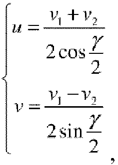
wherein y is an angle between the first return light signal and the second return light signal, λ 1 is the wavelength of the first light signal, λ 2 is the wavelength of the second light signal, f 1 is the frequency of the first light signal, f 2 is the frequency of the second light signal, f p1 and f p2 are two peak frequencies in the power spectrum of the return light signal, the wind velocity is

- In the above implementation process, the wind velocity and the wind direction in the wind field information can be obtained through vector operation according to the information carried in the first return light signal and the second return light signal, and thereby more accurate information of the wind field in front of the wind turbine can be obtained.
- Optionally, the nacelle-based lidar further comprises a pulse generator, the pulse generator being connected to the frequency modulator; the transmitting, by the frequency modulator, a first light pulse signal obtained after frequency modulation on the first light signal and a second light pulse signal obtained after frequency modulation on the second light signal comprises: acquiring, by the frequency modulator, a first pulse signal and a second pulse signal generated by the pulse generator; performing, by the frequency modulator, frequency modulation on the first light signal x = cos(2πf 1 t) and the first pulse signal to obtain a first transmit signal


wherein f 1 is the frequency of the first light signal, f 2 is the frequency of the second light signal, τ is pulse width, T is a repetition cycle of the pulse signal, Δf 1 is a frequency shift of the first light signal, and Δf 2 is a frequency shift of the second light signal. - In the above implementation process, the pulse generator generates the pulse signals, and the frequency modulator performs frequency modulation on the first light signal and the second light signal based on the pulse signals, so that the frequency modulator does not need to generate pulse signals for the frequency modulation on the light signals, thereby reducing the data processing load of the frequency modulator.
- Optionally, to ensure that aliasing does not occur in the frequency spectrum of the return light signals, |f 1-f 2|>Δf 1 and |f 1-f 2|>Δf 2.
- Optionally, to ensure that Doppler frequencies of the two light pulse signals can be distinguished from each other, Δf 1 differs from Δf 2 by a preset frequency value.
- Optionally, the signal processing device comprises a coupler and a signal processor, the coupler being connected to the multi-wavelength laser, the beam combiner, and the signal processor; before the acquiring, by the signal processing device, a return light signal formed in a manner of combining, by the beam combiner, a first return light signal returned after the first light pulse signal is scattered by aerosols in the atmosphere and a second return light signal returned after the second light pulse signal is scattered by aerosols in the atmosphere, the method further comprises: beating, by the coupler, the obtained initial return light signal with the light signal to obtain the return light signal,
wherein the initial return light signal is

i=1, 2, fi is the frequency corresponding to the i th light signal, Δfi is a frequency shift corresponding to the i th wavelength, and fdi is a Doppler frequency of the return light signal. - In the above implementation process, since the frequency of the return light signal is generally large, the beating of the return light signal with the light signal by the coupler facilitates subsequent optical-to-electrical conversion of the return light signal.
- Optionally, the signal processing device further comprises a sampler, the sampler being connected to the coupler and the signal processor; before the obtaining, by the signal processing device, wind field information based on the return light signal, the method further comprises:
- sampling, by the sampler, the return light signal to obtain a sampled return light signal,
- wherein the sampling frequency satisfies the Nyquist sampling theorem: Fs ≥ 2Max(Δfi +B/2), the sampled return light signal is

- In a second aspect of the present disclosure, a nacelle-based lidar is provided, which is mounted on a wind turbine and comprises a multi-wavelength laser, a beam splitter, a frequency modulator, a beam combiner, and a signal processing device, the multi-wavelength laser is connected to the beam splitter, the beam splitter is connected to the frequency modulator, the frequency modulator is connected to the signal processing device, and the beam combiner is connected to the signal processing device;
the multi-wavelength laser is used for sending light signals having at least two different wavelengths;
the beam splitter is used for splitting the light signals into at least a first light signal and a second light signal, the wavelength of the first light signal being a first wavelength, and the wavelength of the second light signal being a second wavelength;
the frequency modulator is used for transmitting a first light pulse signal obtained after frequency modulation on the first light signal and a second light pulse signal obtained after frequency modulation on the second light signal;
the signal processing device is used for acquiring a return light signal formed in a manner of combining, by the beam combiner, a first return light signal returned after the first light pulse signal is scattered by aerosols in the atmosphere and a second return light signal returned after the second light pulse signal is scattered by aerosols in the atmosphere; and
the signal processing device is further used for obtaining wind field information based on the return light signal. - Optionally, the signal processing device is further used for calculating a power spectrum of the return light signal; and obtaining the wind field information according to the power spectrum of the return light signal.
- Optionally, the signal processing device is further used for obtaining a first radial velocity based on v 1 = λ 1(f p
1 -f 1)/2 or v 1 = λ 1(f p2 -f 1)/2; obtaining a second radial velocity based on v 2 = λ 1(f p2 -f 2)/2 or v 2 = λ 2(f p1 -f 2)/2; and obtaining wind velocity and wind direction in the wind field information based on
wherein y is an angle between the first return light signal and the second return light signal, λ 1 is the wavelength of the first light signal, λ 2 is the wavelength of the second light signal, f 1 is the frequency of the first light signal, f 2 is the frequency of the second light signal, f p1 and f p2 are two peak frequencies in the power spectrum of the return light signal, the wind velocity is

- Optionally, the nacelle-based lidar further comprises a pulse generator, the pulse generator being connected to the frequency modulator;
the frequency modulator is further used for acquiring a first pulse signal and a second pulse signal generated by the pulse generator;
the frequency modulator is further used for performing frequency modulation on the first light signal x = cos(2πf 1 t) and the first pulse signal to obtain a first transmit signal
the frequency modulator is further used for performing frequency modulation on the second light signal x = cos(2πf 2 t) and the second pulse signal to obtain a second transmit signal
wherein f 1 is the frequency of the first light signal, f 2 is the frequency of the second light signal, τ is pulse width, T is a repetition cycle of the pulse signal, Δf 1 is a frequency shift of the first light signal, and Δf 2 is a frequency shift of the second light signal. - Optionally, |f 1-f 2|>Δf1 and |f 1-f 2|>Δf 2.
- Optionally, Δf 1 differs from Δf 2 by a preset frequency value.
- Optionally, the signal processing device comprises a coupler and a signal processor, the coupler being connected to the multi-wavelength laser, the beam combiner, and the signal processor;
the coupler is used for beating the obtained initial return light signal with the light signal to obtain the return light signal,
wherein the initial return light signal is

i=1, 2, fi is the frequency corresponding to the i th light signal, Δfi is a frequency shift corresponding to the i th wavelength, and fdi is a Doppler frequency of the return light signal. - Optionally, the signal processing device further comprises a sampler, the sampler being connected to the coupler and the signal processor;
the sampler is used for sampling the return light signal to obtain a sampled return light signal,
wherein the sampling frequency satisfies the Nyquist sampling theorem: Fs ≥ 2Max(Δfi +B/2), the sampled return light signal is
- Optionally, the signal processing device further comprises a balanced detector, the balanced detector being connected to the coupler and the sampler.
- Optionally, the nacelle-based lidar further comprises a circulator, the circulator being connected to the frequency modulator and the beam splitter.
- Optionally, the nacelle-based lidar further comprises a first optical filter and a second optical filter, the first optical filter and the second optical filter being both connected to the beam splitter; the first optical filter is used for filtering the first light signal and then sending the signal to the frequency modulator; and the second optical filter is used for filtering the second light signal and then sending the signal to the frequency modulator.
- Compared with the prior art, the present disclosure has the following beneficial effects:
Embodiments of the present disclosure provide a wind field information measurement method and a nacelle-based lidar. In the method, the multi-wavelength laser sends light signals having at least two different wavelengths; the beam splitter splits the light signals into at least a first light signal and a second light signal; the frequency modulator transmits a first light pulse signal obtained after frequency modulation on the first light signal and a second light pulse signal obtained after frequency modulation on the second light signal; the signal processing device acquires a return light signal formed in a manner of combining, by the beam combiner, a first return light signal returned after the first light pulse signal is scattered by aerosols in the atmosphere and a second return light signal returned after the second light pulse signal is scattered by aerosols in the atmosphere; and the signal processing device obtains wind field information based on the return light signal. Therefore, in this solution, the wind field information is measured by simultaneously transmitting at least two light signals having different wavelengths, so that the wind field information can be accurately measured in real time and the data effective rate and data refresh rate can be effectively improved, thereby avoiding the problem in the prior art that because two light signals are periodically and alternately transmitted for measurement of the wind field information and a single beam is blocked by an impeller of the wind turbine, the data refresh rate and data effective rate are reduced and the wind field information in the transmission time interval cannot be measured, resulting in inaccurate measurement of the wind field information. - To describe the technical solutions in the embodiments of the present disclosure more clearly, the following briefly introduces the accompanying drawings required for describing the embodiments. It should be understood that, the accompanying drawings in the following description show merely some embodiments of the present disclosure, and shall not be construed as limitations to the scope of the present disclosure. Persons of ordinary skill in the art can derive other related drawings from these accompanying drawings without creative efforts.
-
FIG. 1 is a schematic diagram showing the installation of a nacelle-based lidar according to an embodiment of the present disclosure; -
FIG. 2 is a schematic diagram showing a structure of the nacelle-based lidar according to an embodiment of the present disclosure; -
FIG. 3 is a schematic diagram of wind field information according to an embodiment of the present disclosure; -
FIG. 4 is a schematic diagram showing another structure of the nacelle-based lidar according to an embodiment of the present disclosure; -
FIG. 5 is a schematic diagram showing range gate division of a return light signal according to an embodiment of the present disclosure; and -
FIG. 6 is a flow chart of a wind field information measurement method according to an embodiment of the present disclosure. - Reference signs: 100, nacelle-based lidar; 110, multi-wavelength laser; 120, beam splitter; 130, frequency modulator; 132, first frequency modulator; 134, second frequency modulator; 140, signal processing device; 142, coupler; 144, signal processor; 146, sampler; 148, balanced detector; 150, beam combiner; 160, first optical filter; 170, second optical filter; 180, first pulse generator; 190, second pulse generator; 200, circulator.
- In order to make the objectives, technical solutions, and advantages of the embodiments of the present disclosure clearer, the technical solutions in the embodiments of the present disclosure are clearly and completely described below with reference to the accompanying drawings of the embodiments of the present disclosure. Apparently, the described embodiments are merely a part rather than all of the embodiments of the present disclosure. The components described and demonstrated in the accompanying drawings of the embodiments of the present disclosure can generally be arranged and designed in various configurations.
- Therefore, the detailed descriptions of the embodiments of the present disclosure with reference to the accompanying drawings are not intended to limit the protection scope of the present disclosure, but merely illustrate selected embodiments of the present disclosure. Based on the embodiments of the present disclosure, all other embodiments obtained by persons of ordinary skill in the art without creative efforts shall fall within the protection scope of the present disclosure.
- It should be noted that, similar reference numerals and letters indicate similar items in the following figures. Therefore, once an item is defined in one figure, it does not need to be further defined and explained in the subsequent figures.
- In the description of the present disclosure, it should be noted that the terms "first", "second", "third", and the like are only used for distinguishing, instead of indicating or implying relative importance.
- In the description of the present disclosure, it should also be noted that, unless otherwise clearly specified and limited, the terms "setup", "installation", "interconnection", and "connection" should be understood in a broad sense. For example, it may be fixed connection, detachable connection, or integral connection; it may be mechanical connection or electrical connection; it may be direct connection or indirect connection through a medium, and it may be internal communication between two elements. For persons of ordinary skill in the art, the specific meanings of the above terms in the present disclosure can be understood according to specific situations.
- Referring to
FIG. 1 and FIG. 2, FIG. 1 is a schematic diagram showing the installation of a nacelle-basedlidar 100 according to an embodiment of the present disclosure, andFIG. 2 is a structural diagram of the nacelle-basedlidar 100 according to an embodiment of the present disclosure. The nacelle-basedlidar 100 is mounted on a wind turbine and includes amulti-wavelength laser 110, abeam splitter 120, afrequency modulator 130, abeam combiner 150, and asignal processing device 140. Themulti-wavelength laser 110 is connected to thebeam splitter 120, thebeam splitter 120 is connected to thefrequency modulator 130, thefrequency modulator 130 is connected to thesignal processing device 140, and thebeam combiner 150 is connected to thesignal processing device 140. - The
multi-wavelength laser 110 is used for sending light signals having at least two different wavelengths. - The
beam splitter 120 is used for splitting the light signals into at least a first light signal and a second light signal, the wavelength of the first light signal being a first wavelength, the wavelength of the second light signal being a second wavelength, and the first wavelength being different from the second wavelength. - The
frequency modulator 130 is used for transmitting a first light pulse signal obtained after frequency modulation on the first light signal and a second light pulse signal obtained after frequency modulation on the second light signal. - The
beam combiner 150 is used for acquiring a first return light signal returned after the first light pulse signal is scattered by aerosols in the atmosphere and a second return light signal returned after the second light pulse signal is scattered by aerosols in the atmosphere, and combining the first return light signal and the second return light signal into a return light signal. - The
signal processing device 140 is used for acquiring the return light signal formed by thebeam combiner 150. - The
signal processing device 140 is further used for obtaining wind field information based on the return light signal, the wind field information being information of the wind field in front of the wind turbine. - Since the
multi-wavelength laser 110 sends light signals having at least two different wavelengths, if the light signals have two wavelengths, the light signals can be denoted by: x = cos(2πf 1 t)+cos(2πf 2 t), wherein f 1 is the frequency of the first light signal, f 2 is the frequency of the second light signal, f 1 =c/λ 1 and f 2 =c/λ 2 , λ 1 is the wavelength of the first light signal, that is, a first wavelength, and λ 2 is the wavelength of the second light signal, that is, a second wavelength. - To enable some parameters of the first light signal and the second light signal, such as amplitude, frequency, phase, polarization state, and duration to vary following a certain pattern, the frequencies of the first light signal and the second light signal need to be modulated, that is, the
frequency modulator 130 is used for transmitting a first light pulse signal and a second light pulse signal obtained after frequency modulation on the first light signal and the second light signal. Thefrequency modulator 130 may be specifically an acousto-optical modulator (AOM) adopted to perform frequency modulation on the two light signals. - The first return light signal returned after the first light pulse signal is scattered by aerosols in the atmosphere is received by an optical antenna in the nacelle-based
lidar 100, and the second return light signal returned after the second light pulse signal is scattered by aerosols in the atmosphere is received by the optical antenna in the nacelle-basedlidar 100. Thebeam combiner 150 combines the first return light signal and the second return light signal into a return light signal, and thesignal processing device 140 obtains the wind field information based on the return light signal. - The light signal is scattered after being transmitted into the atmosphere, and is then received by a telescope in the nacelle-based
lidar 100, that is, the telescope receives the return light signal carrying information of a Doppler shift caused by the atmospheric wind field, and thesignal processing device 140 can calculate the wind velocity and direction, that is, obtain the wind field information by measuring the Doppler shift of the return light signal. - Therefore, in the embodiment of the present disclosure, the
multi-wavelength laser 110 sends light signals having at least two different wavelengths, and thebeam splitter 120 splits the light signals into two light signals, that is, the nacelle-basedlidar 100 simultaneously transmits at least two light signals, and then thesignal processing device 140 obtains the wind field information based on the received return light signal. Therefore, the wind field information is measured by simultaneously transmitting two light signals of different wavelengths, and the wind field information can be measured in real time, thereby improving the measurement accuracy of the wind field information. - In view of the above embodiment, the
signal processing device 140 may obtain the wind field information based on the return light signal in the following manner: thesignal processing device 140 calculates a power spectrum of the return light signal, and obtains the wind field information according to the power spectrum of the return light signal. Since the power spectrum of the return light signal carries corresponding wind field information, it is more convenient to obtain the wind field information according to the power spectrum of the return light signal. - Specifically, as shown in
FIG. 3 , the wind field information generally includes wind velocity and wind direction which can be obtained from the information carried in the two return light signals, for example, the power spectrum of the return light signal includes two signal peak values f p1 and f p2 which are frequency spectrum peak values corresponding to the two return light signals, if |f p1 -f 1|≤|f p2 -f 1|, the radial velocities are calculated by the formulas: v 1 = λ 1(f p1 -f 1)/2 v 2 = λ 2(f p2 -f 2)/2 and if |f p1 -f 1|>|f p2 -f 1|, the radial velocities are calculated by the formulas: v 1 = λ 1(f p2 -f 1)/2, v 2 = λ 2(f p1 -f 2)/2. Therefore, thesignal processing device 140 can obtain the first radial velocity based on v 1 = λ 1(f p1 -f 1)/2 or v 1 = λ 1(f p2 -f 1)/2, obtain the second radial velocity based on v 2 = λ 2(f p2 -f 2)/2 or v 2 = λ 2(f p1 -f 2)/2, and obtain the wind velocity and the wind direction in the wind field information based on
- In the above formulas, γ is an angle between the first return light signal and the second return light signal, λ 1 is the wavelength of the first light signal, λ 2 is the wavelength of the second light signal, f 1 is the frequency of the first light signal, f 2 is the frequency of the second light signal, f p1 and f p2 are two peak frequencies in the power spectrum of the return light signal, the wind velocity is


signal processing device 140 can obtain the wind velocity and the wind direction in the wind field information in the above manner. - In the above implementation process, the wind velocity and the wind direction in the wind field information can be obtained through vector operation according to the information carried in the first return light signal and the second return light signal, and thereby more accurate information of the wind field in front of the wind turbine can be obtained.
- Referring to
FIG. 4, FIG. 4 is a schematic diagram showing another structure of the nacelle-basedlidar 100 according to an embodiment of the present disclosure. The nacelle-basedlidar 100 further includes a firstoptical filter 160 and a secondoptical filter 170. The firstoptical filter 160 and the secondoptical filter 170 are both connected to thebeam splitter 120. Thebeam splitter 120 splits the light signals into a first light signal and a second light signal, inputs the first light signal and the second light signal into the firstoptical filter 160, and inputs the first light signal and the second light signal into the second filter. After the first light signal and the second light signal pass through the firstoptical filter 160, the wavelength component of the second light signal is filtered out by the firstoptical filter 160, and thus the firstoptical filter 160 outputs the first light signal. After the first light signal and the second light signal pass through the secondoptical filter 170, the wavelength component of the first light signal is filtered out by the secondoptical filter 170, and thus the secondoptical filter 170 outputs the second light signal. - The nacelle-based
lidar 100 may further include a pulse generator. The pulse generator is connected to thefrequency modulator 130, and is used for generating pulse signals of different frequencies and inputting the pulse signals into thefrequency modulator 130. Then, thefrequency modulator 130 performs frequency modulation on the first light signal and the second light signal based on the pulse signals. - Specifically, the first light signal is denoted by x = cos(2πf 1 t), and the
frequency modulator 130 performs frequency modulation on the first light signal and the first pulse signal generated by the pulse generator to obtain a first transmit signal
frequency modulator 130 performs frequency modulation on the second light signal and the second pulse signal generated by the pulse generator to obtain a second transmit signal
- In the above implementation process, the pulse generator generates the pulse signals, and the frequency modulator performs frequency modulation on the first light signal and the second light signal based on the pulse signals, so that the frequency modulator does not need to generate pulse signals for the frequency modulation on the light signals, thereby reducing the data processing load of the frequency modulator.
- To raise the signal processing speed, the pulse generator may include a
first pulse generator 180 and asecond pulse generator 190. Thefirst pulse generator 180 is used for generating a first pulse signal and inputting the signal into thefrequency modulator 130. Thesecond pulse generator 190 is used for generating a second pulse signal and inputting the signal into thefrequency modulator 130. Definitely, to ensure that the two light pulse signals can be sent simultaneously, thefrequency modulator 130 may also include afirst frequency modulator 132 and a second frequency modulator 134. Thefirst frequency modulator 132 is used for receiving the first pulse signal and the first light signal, and performing frequency modulation on the first light signal. The second frequency modulator 134 is used for receiving the second pulse signal and the second light signal, and performing frequency modulation on the second light signal. - Further, to ensure that aliasing does not occur in the frequency spectrum of the first return light signal and the second return light signal, |f 1-f 2|>Δf 1 and |f 1-f 2|>Δf 2, and the value of |f 1-f 2| is much larger than Δf 1 or Δf2.
- To ensure that Doppler frequencies of wind velocity of the two beams can be distinguished from each other, Δf 1 differs from Δf 2 by a preset frequency value, that is, Δf 1 and Δf 2 are at a certain interval.
- In a possible implementation manner, the
signal processing device 140 further includes acoupler 142 and asignal processor 144. Thecoupler 142 is connected to themulti-wavelength laser 110, the beam combiner, and thesignal processor 144. Thecoupler 142 is used for beating the return light signal with the seed light signal. Thecoupler 142 firstly receives the initial return light signal, and then beats the initial return light signal with the light signal to obtain the return light signal. Thesignal processor 144 is used for receiving the return light signal, and obtaining the wind field information according to the return light signal. The initial return light signal is

i is a Doppler frequency of the return light signal. - In the above implementation process, since the frequency of the return light signal is generally large, the beating of the return light signal with the light signal by the coupler facilitates subsequent sampling of the return light signal.
- In a possible implementation manner, the
signal processing device 140 further includes asampler 146. Thesampler 146 is connected to thecoupler 142 and thesignal processor 144. Thesampler 146 is used for implementing conversion from an analog signal to a digital signal, that is, before thesignal processing device 140 obtains the wind field information based on the return light signal, thesampler 146 samples the return light signal to obtain a sampled return light signal. To avoid aliasing in the frequency spectrum, the sampling frequency needs to satisfy the Nyquist sampling theorem, and assuming that the required signal bandwidth is B, the sampling frequency satisfies the relationship of: Fs ≥ 2Max(Δfi +B/2), and the sampled return light signal is:
- In the above implementation process, since the sampler is used for sampling the return light signal, the
signal processor 144 does not need to perform sampling, thereby reducing the data processing pressure of thesignal processor 144. - During the measurement of the wind field information, the signal processor 144140 firstly calculates the power spectrum of the received return light signal in the following process: performing range gate division on the return light signal, calculating the power spectrum of each range gate, and after pulse accumulation for a certain period of time, removing the background noise to obtain the signal power spectrum.
- As shown in
FIG. 5, FIG. 5 is a schematic diagram showing range gate division of a return light signal. Since the nacelle-basedlidar 100 needs to simultaneously measure the wind field information of multiple range gates, the position of the initial point needs to be calculated according to the distance from the measurement section. As shown inFIG. 5 , the distance from the section is R, and the position of the initial point is:
- To improve the operation efficiency, the power spectrum of the return light signal is calculated by using a periodogram method, and Fourier transform (FFT) is performed on the sampled return light signal s(n) to obtain the power spectrum of the return light signal:

- Therefore, after obtaining the power spectrum of the return light signal, the
signal processor 144 can calculate the wind field information based on the power spectrum in a manner that is shown in the above embodiment and will not be described herein again. - In a possible implementation manner, the
signal processing device 140 may also include abalanced detector 148. Thebalanced detector 148 is connected to thecoupler 142 and thesampler 146. Definitely, thebalanced detector 148 may also be connected to thecoupler 142 and thesampler 146. Thebalanced detector 148 is used for implementing conversion between light signals and electrical signals and suppressing common-mode signals. - Further, in a possible implementation manner, the nacelle-based
lidar 100 may also include acirculator 200. Thecirculator 200 is connected to thefrequency modulator 130 and thebeam splitter 120, and is used for isolating transmit/receive signals. When the light signal is transmitted, the light signal can only pass through an output port almost without loss, and thus the strength of the reflected signal on a receiving branch section is suppressed. - In a possible implementation manner, the nacelle-based
lidar 100 may also include an optical antenna used for improving the transmitting/receiving efficiency of the light signal. During signal transmission, the transmission distance of the light signal can be ensured as much as possible by adjusting the focal length of the telescope in the nacelle-basedlidar 100. During signal reception, the telescope can gather return light scattered in different directions and converge into collimated light, thereby improving the receiving efficiency. - Referring to
FIG. 6, FIG. 6 is a flow chart of a wind field information measurement method according to an embodiment of the present disclosure. The method is applied in the nacelle-based lidar, and includes the following steps. - Step S110: the multi-wavelength laser sends light signals having at least two different wavelengths.
- Step S120: the beam splitter splits the light signals into at least a first light signal and a second light signal.
- The wavelength of the first light signal is a first wavelength, and the wavelength of the second light signal is a second wavelength.
- Step S130: the frequency modulator transmits a first light pulse signal obtained after frequency modulation on the first light signal and a second light pulse signal obtained after frequency modulation on the second light signal.
- Step S140: the signal processing device acquires a return light signal formed in a manner of combining, by the beam combiner, a first return light signal returned after the first light pulse signal is scattered by aerosols in the atmosphere and a second return light signal returned after the second light pulse signal is scattered by aerosols in the atmosphere.
- Step S150: the signal processing device obtains wind field information based on the return light signal.
- Optionally, the obtaining, by the signal processing device, wind field information based on the return light signal includes: calculating, by the signal processing device, a power spectrum of the return light signal; and obtaining, by the signal processing device, the wind field information according to the power spectrum of the return light signal.
- Optionally, the obtaining, by the signal processing device, the wind field information according to the power spectrum of the return light signal includes: obtaining, by the signal processing device, a first radial velocity based on v 1 = λ 1(f p
1 -f 1)/2 or v 1 = λ 1(f p2 -f 1)/2 obtaining, by the signal processing device, a second radial velocity based on v 2 = λ 2(f p2 -f 2)/2 or v 2 = λ 2(f p1 -f 2)/2 and obtaining, by the signal processing device, wind velocity and wind direction in the wind field information based on
wherein y is an angle between the first return light signal and the second return light signal, λ 1 is the wavelength of the first light signal, λ 2 is the wavelength of the second light signal, f 1 is the frequency of the first light signal, f 2 is the frequency of the second light signal, f p1 and f p2 are two peak frequencies in the power spectrum of the return light signal, the wind velocity is

- Optionally, the nacelle-based lidar further includes a pulse generator, the pulse generator being connected to the frequency modulator; the transmitting, by the frequency modulator, a first light pulse signal obtained after frequency modulation on the first light signal and a second light pulse signal obtained after frequency modulation on the second light signal includes: acquiring, by the frequency modulator, a first pulse signal and a second pulse signal generated by the pulse generator; performing, by the frequency modulator, frequency modulation on the first light signal x = cos(2πf 1 t) and the first pulse signal to obtain a first transmit signal


wherein f 1 is the frequency of the first light signal, f 2 is the frequency of the second light signal, τ is pulse width, T is a repetition cycle of the pulse signal, Δf 1 is a frequency shift of the first light signal, and Δf 2 is a frequency shift of the second light signal. - Optionally, to ensure that aliasing does not occur in the frequency spectrum of the return light signals, |f 1-f 2|>Δf 1 and |f 1-f 2|>Δf 2.
- Optionally, to ensure that Doppler frequencies of the two light pulse signals can be distinguished from each other, Δf 1 differs from Δf 2 by a preset frequency value.
- Optionally, the signal processing device includes a coupler and a signal processor, the coupler being connected to the multi-wavelength laser, the beam combiner, and the signal processor; before the acquiring, by the signal processing device, a return light signal formed in a manner of combining, by the beam combiner, a first return light signal returned after the first light pulse signal is scattered by aerosols in the atmosphere and a second return light signal returned after the second light pulse signal is scattered by aerosols in the atmosphere, the method further includes: beating, by the coupler, the obtained initial return light signal with the light signal to obtain the return light signal,
wherein the initial return light signal is

i=1, 2, fi is the frequency corresponding to the i th light signal, Δfi is a frequency shift corresponding to the i th wavelength, and fdi is a Doppler frequency of the return light signal. - Optionally, the signal processing device further includes a sampler, the sampler being connected to the coupler and the signal processor; before the obtaining, by the signal processing device, wind field information based on the return light signal, the method further includes:
- sampling, by the sampler, the return light signal to obtain a sampled return light signal,
- wherein the sampling frequency satisfies the Nyquist sampling theorem: Fs ≥ 2Max(Δfi +B/2), the sampled return light signal is

- Persons skilled in the art can clearly understand that, for the convenience and conciseness of the description, the specific working process of the device described above can be known with reference to the corresponding process in the aforementioned method, and will not be described herein again.
- In view of the above, the embodiments of the present disclosure provide a wind field information measurement method and a nacelle-based lidar. In the method, the multi-wavelength laser sends light signals having at least two different wavelengths; the beam splitter splits the light signals into at least a first light signal and a second light signal; the frequency modulator transmits a first light pulse signal obtained after frequency modulation on the first light signal and a second light pulse signal obtained after frequency modulation on the second light signal; the signal processing device acquires a return light signal formed in a manner of combining, by the beam combiner, a first return light signal returned after the first light pulse signal is scattered by aerosols in the atmosphere and a second return light signal returned after the second light pulse signal is scattered by aerosols in the atmosphere; and the signal processing device obtains wind field information based on the return light signal. Therefore, in this solution, the wind field information is measured by simultaneously transmitting at least two light signals having different wavelengths, so that the wind field information can be measured in real time, thereby avoiding the problem in the prior art that because two light signals are periodically and alternately transmitted for measurement of the wind field information and a single beam is blocked by an impeller of the wind turbine, the data refresh rate and data effective rate are reduced and the wind field information in the transmission time interval cannot be measured, resulting in inaccurate measurement of the wind field information.
- The foregoing descriptions are merely preferred embodiments of the present disclosure, and are not intended to limit the present disclosure. It is apparent to persons skilled in the art that, the present disclosure may have various modifications and changes. Any modification, equivalent replacement, improvement, etc. made within the spirit and principle of the present disclosure shall fall within the protection scope of the present disclosure.
- The present disclosure can measure the wind field information in real time, thereby avoiding the problem in the prior art that because two light signals are periodically and alternately transmitted for measurement of the wind field information and a single beam is blocked by an impeller of the wind turbine, the data effective rate is reduced and the wind field information in the transmission time interval cannot be measured, resulting in inaccurate measurement of the wind field information.
Claims (19)
- A wind field information measurement method, characterized in that the method is applied in a nacelle-based lidar, the nacelle-based lidar is mounted on a wind turbine and comprises a multi-wavelength laser, a beam splitter, a frequency modulator, a beam combiner, and a signal processing device, the multi-wavelength laser is connected to the beam splitter, the beam splitter is connected to the frequency modulator, the frequency modulator is connected to the signal processing device, and the beam combiner is connected to the signal processing device, the method comprising:sending, by the multi-wavelength laser, light signals having at least two different wavelengths;splitting, by the beam splitter, the light signals into at least a first light signal and a second light signal, the wavelength of the first light signal being a first wavelength, and the wavelength of the second light signal being a second wavelength;transmitting, by the frequency modulator, a first light pulse signal obtained after frequency modulation on the first light signal and a second light pulse signal obtained after frequency modulation on the second light signal;acquiring, by the signal processing device, a return light signal formed in a manner of combining, by the beam combiner, a first return light signal returned after the first light pulse signal is scattered by aerosols in the atmosphere and a second return light signal returned after the second light pulse signal is scattered by aerosols in the atmosphere; andobtaining, by the signal processing device, wind field information based on the return light signal.
- The method according to claim 1, characterized in that the obtaining, by the signal processing device, the wind field information based on the return light signal comprises:calculating, by the signal processing device, a power spectrum of the return light signal; andobtaining, by the signal processing device, the wind field information according to the power spectrum of the return light signal.
- The method according to claim 2, characterized in that the obtaining, by the signal processing device, the wind field information according to the power spectrum of the return light signal comprises:obtaining, by the signal processing device, a first radial velocity based on v 1 = λ 1(f p
1 -f 1)/2 or v 1 = λ 1(f p2 -f 1)/2;obtaining, by the signal processing device, a second radial velocity based on v 1 = λ 2(f p2 -f 2)/2 or v 2 = λ 2(f p1 -f 2)/2; andobtaining, by the signal processing device, wind velocity and wind direction in the wind field information based on wherein y is an angle between the first return light signal and the second return light signal, λ 1 is the wavelength of the first light signal, λ 2 is the wavelength of the second light signal, f 1 is the frequency of the first light signal, f 2 is the frequency of the second light signal, f p1 and f p2 are two peak frequencies in the power spectrum of the return light signal, the wind velocity is

- The method according to claim 1, characterized in that the nacelle-based lidar further comprises a pulse generator, the pulse generator being connected to the frequency modulator; the transmitting, by the frequency modulator, a first light pulse signal obtained after frequency modulation on the first light signal and a second light pulse signal obtained after frequency modulation on the second light signal comprises:acquiring, by the frequency modulator, a first pulse signal and a second pulse signal generated by the pulse generator;performing, by the frequency modulator, frequency modulation on the first light signal x = cos(2πf 1 t) and the first pulse signal to obtain a first transmit signal
 performing, by the frequency modulator, frequency modulation on the second light signal x = cos(2πf 2 t) and the second pulse signal to obtain a second transmit signal
 wherein f 1 is the frequency of the first light signal, f 2 is the frequency of the second light signal, τ is pulse width, T is a repetition cycle of the pulse signal, Δf 1 is a frequency shift of the first light signal, and Δf 2 is a frequency shift of the second light signal.
 - The method according to claim 4, characterized in that |f 1-f 2|>Δf 1 and |f 1-f 2|>Δf 2.
- The method according to claim 4, characterized in that Δf 1 differs from Δf 2 by a preset frequency value.
- The method according to claim 1, characterized in that the signal processing device comprises a coupler and a signal processor, the coupler being connected to the multi-wavelength laser, the beam combiner, and the signal processor; before the acquiring, by the signal processing device, a return light signal formed in a manner of combining, by the beam combiner, a first return light signal returned after the first light pulse signal is scattered by aerosols in the atmosphere and a second return light signal returned after the second light pulse signal is scattered by aerosols in the atmosphere, the method further comprises:beating, by the coupler, the obtained initial return light signal with the light signal to obtain the return light signal,wherein the initial return light signal is

 i=1, 2, fi is the frequency corresponding to the i th light signal, Δfi is a frequency shift corresponding to the i th wavelength, and fdi is a Doppler frequency of the return light signal.
 - The method according to claim 7, characterized in that the signal processing device further comprises a sampler, the sampler being connected to the coupler and the signal processor; before the obtaining, by the signal processing device, wind field information based on the return light signal, the method further comprises:sampling, by the sampler, the return light signal to obtain a sampled return light signal,wherein the sampling frequency satisfies the Nyquist sampling theorem: Fs ≥ 2Max(Δfi +B/2), the sampled return light signal is

- A nacelle-based lidar, characterized in that the nacelle-based lidar is mounted on a wind turbine and comprises a multi-wavelength laser, a beam splitter, a frequency modulator, a beam combiner, and a signal processing device, the multi-wavelength laser is connected to the beam splitter, the beam splitter is connected to the frequency modulator, the frequency modulator is connected to the signal processing device, and the beam combiner is connected to the signal processing device;
the multi-wavelength laser is used for sending light signals having at least two different wavelengths;
the beam splitter is used for splitting the light signals into at least a first light signal and a second light signal, the wavelength of the first light signal being a first wavelength, and the wavelength of the second light signal being a second wavelength;
the frequency modulator is used for transmitting a first light pulse signal obtained after frequency modulation on the first light signal and a second light pulse signal obtained after frequency modulation on the second light signal;
the signal processing device is used for acquiring a return light signal formed in a manner of combining, by the beam combiner, a first return light signal returned after the first light pulse signal is scattered by aerosols in the atmosphere and a second return light signal returned after the second light pulse signal is scattered by aerosols in the atmosphere; and
the signal processing device is further used for obtaining wind field information based on the return light signal. - The nacelle-based lidar according to claim 9, characterized in that the signal processing device comprises a signal processor, and the signal processor is used for calculating a power spectrum of the return light signal; and obtaining the wind field information according to the power spectrum of the return light signal.
- The nacelle-based lidar according to claim 9, characterized in that the signal processing device is further used for obtaining a first radial velocity based on v 1 = λ 1(f p
1 -f 1)/2 or v 1 = λ 1(f p2 -f 1)/2 obtaining a second radial velocity based on v 2 = λ 2(f p2 -f 2)/2 or v 2 = λ 2(f p1 -f 2)/2; and obtaining wind velocity and wind direction in the wind field information based on
wherein y is an angle between the first return light signal and the second return light signal, λ 1 is the wavelength of the first light signal, λ 2 is the wavelength of the second light signal, f 1 is the frequency of the first light signal, f 2 is the frequency of the second light signal, f p1 and f p2 are two peak frequencies in the power spectrum of the return light signal, the wind velocity is

- The nacelle-based lidar according to claim 9, characterized in that the nacelle-based lidar further comprises a pulse generator, the pulse generator being connected to the frequency modulator;
the frequency modulator is further used for acquiring a first pulse signal and a second pulse signal generated by the pulse generator;
the frequency modulator is further used for performing frequency modulation on the first light signal x = cos(2πf 1 t) and the first pulse signal to obtain a first transmit signal
the frequency modulator is further used for performing frequency modulation on the second light signal x = cos(2πf 2 t) and the second pulse signal to obtain a second transmit signal
wherein f 1 is the frequency of the first light signal, f 2 is the frequency of the second light signal, τ is pulse width, T is a repetition cycle of the pulse signal, Δf 1 is a frequency shift of the first light signal, and Δf 2 is a frequency shift of the second light signal. - The nacelle-based lidar according to claim 12, characterized in that |f 1-f 2|>Δf 1 and |f 1-f 2|>Δf 2.
- The nacelle-based lidar according to claim 12, characterized in that Δf 1 differs from Δf 2 by a preset frequency value.
- The nacelle-based lidar according to claim 9, characterized in that the signal processing device comprises a coupler and a signal processor, the coupler being connected to the multi-wavelength laser, the beam combiner, and the signal processor;
the coupler is used for beating the obtained initial return light signal with the light signal to obtain the return light signal,
wherein the initial return light signal is

i=1, 2, fi is the frequency corresponding to the i th light signal, Δfi is a frequency shift corresponding to the i th wavelength, and fdi is a Doppler frequency of the return light signal. - The nacelle-based lidar according to claim 15, characterized in that the signal processing device further comprises a sampler, the sampler being connected to the coupler and the signal processor;
the sampler is used for sampling the return light signal to obtain a sampled return light signal,
wherein the sampling frequency satisfies the Nyquist sampling theorem: Fs ≥ 2Max(Δfi +B/2), the sampled return light signal is
- The nacelle-based lidar according to claim 16, characterized in that the signal processing device further comprises a balanced detector, the balanced detector being connected to the coupler and the sampler.
- The nacelle-based lidar according to claim 9, characterized in that the nacelle-based lidar further comprises a circulator, the circulator being connected to the frequency modulator and the beam splitter.
- The nacelle-based lidar according to claim 9, characterized in that the nacelle-based lidar further comprises a first optical filter and a second optical filter, the first optical filter and the second optical filter being both connected to the beam splitter;
the first optical filter is used for filtering the first light signal and then sending the signal to the frequency modulator; and
the second optical filter is used for filtering the second light signal and then sending the signal to the frequency modulator.
Applications Claiming Priority (1)
| Application Number | Priority Date | Filing Date | Title |
|---|---|---|---|
| PCT/CN2018/118859 WO2020113356A1 (en) | 2018-12-03 | 2018-12-03 | Wind field information measurement method and engine room-type laser radar |
Publications (2)
| Publication Number | Publication Date |
|---|---|
| EP3783391A1 true EP3783391A1 (en) | 2021-02-24 |
| EP3783391A4 EP3783391A4 (en) | 2021-04-14 |
Family
ID=70974033
Family Applications (1)
| Application Number | Title | Priority Date | Filing Date |
|---|---|---|---|
| EP18942353.6A Withdrawn EP3783391A4 (en) | 2018-12-03 | 2018-12-03 | Wind field information measurement method and engine room-type laser radar |
Country Status (4)
| Country | Link |
|---|---|
| EP (1) | EP3783391A4 (en) |
| AU (2) | AU2018451571A1 (en) |
| CA (1) | CA3100885C (en) |
| WO (1) | WO2020113356A1 (en) |
Cited By (2)
| Publication number | Priority date | Publication date | Assignee | Title |
|---|---|---|---|---|
| WO2022234212A1 (en) * | 2021-05-06 | 2022-11-10 | Office National D'etudes Et De Recherches Aérospatiales | Pulsed lidar system |
| JP2024517454A (en) * | 2021-05-06 | 2024-04-22 | オフィス ナショナル デテュード エ ドゥ ルシェルシュ アエロスパシアル | Pulsed LIDAR System |
Families Citing this family (3)
| Publication number | Priority date | Publication date | Assignee | Title |
|---|---|---|---|---|
| CN114690203A (en) * | 2020-12-29 | 2022-07-01 | 宁波飞芯电子科技有限公司 | Wind measurement laser radar |
| CN113671532B (en) * | 2021-08-10 | 2023-05-30 | 南京牧镭激光科技股份有限公司 | Self-adaptive multichannel wind lidar system |
| CN118979855B (en) * | 2024-10-22 | 2025-02-28 | 中船科技股份有限公司 | Method and equipment for evaluating beam efficiency of wind turbine airborne wind laser radar |
Family Cites Families (10)
| Publication number | Priority date | Publication date | Assignee | Title |
|---|---|---|---|---|
| CN103946716B (en) * | 2011-12-21 | 2016-05-11 | 三菱电机株式会社 | Laser radar apparatus |
| US8930049B2 (en) * | 2012-05-31 | 2015-01-06 | Optical Air Data Systems, Llc | LDV for airdrops |
| GB2532585B (en) * | 2013-06-30 | 2018-04-25 | Wind Farm Analytics Ltd | Turbine fluid velocity field measurement |
| JPWO2016092705A1 (en) * | 2014-12-12 | 2017-04-27 | 三菱電機株式会社 | Laser radar equipment |
| CN105572690B (en) * | 2016-03-07 | 2018-01-30 | 中国科学技术大学 | A kind of double frequency coherent wind laser radar based on the continuous light EOM modulation of single-frequency |
| CN105785395B (en) * | 2016-03-17 | 2018-03-09 | 四川知周科技有限责任公司 | A kind of coherent Doppler LDV technique of multi-wavelength beam synthesis |
| CN106886031B (en) * | 2017-02-27 | 2019-07-26 | 南京红露麟激光雷达科技有限公司 | Rayleigh Doppler anemometry laser radar based on wide range gating coherent detection |
| US10254388B2 (en) * | 2017-03-28 | 2019-04-09 | Luminar Technologies, Inc. | Dynamically varying laser output in a vehicle in view of weather conditions |
| CN206773190U (en) * | 2017-05-31 | 2017-12-19 | 南京先进激光技术研究院 | High sensitivity gaseous contamination detecting laser radar system |
| CN107807367B (en) * | 2017-11-02 | 2019-04-12 | 南京牧镭激光科技有限公司 | A kind of coherent wind laser radar apparatus |
-
2018
- 2018-12-03 WO PCT/CN2018/118859 patent/WO2020113356A1/en not_active Ceased
- 2018-12-03 AU AU2018451571A patent/AU2018451571A1/en not_active Abandoned
- 2018-12-03 CA CA3100885A patent/CA3100885C/en active Active
- 2018-12-03 EP EP18942353.6A patent/EP3783391A4/en not_active Withdrawn
-
2022
- 2022-11-01 AU AU2022263477A patent/AU2022263477A1/en not_active Abandoned
Cited By (3)
| Publication number | Priority date | Publication date | Assignee | Title |
|---|---|---|---|---|
| WO2022234212A1 (en) * | 2021-05-06 | 2022-11-10 | Office National D'etudes Et De Recherches Aérospatiales | Pulsed lidar system |
| FR3122737A1 (en) * | 2021-05-06 | 2022-11-11 | Office National D'etudes Et De Recherches Aérospatiales | PULSE LIDAR SYSTEM |
| JP2024517454A (en) * | 2021-05-06 | 2024-04-22 | オフィス ナショナル デテュード エ ドゥ ルシェルシュ アエロスパシアル | Pulsed LIDAR System |
Also Published As
| Publication number | Publication date |
|---|---|
| CA3100885C (en) | 2022-03-15 |
| AU2022263477A1 (en) | 2022-12-08 |
| AU2018451571A1 (en) | 2020-12-10 |
| CA3100885A1 (en) | 2020-06-11 |
| EP3783391A4 (en) | 2021-04-14 |
| WO2020113356A1 (en) | 2020-06-11 |
Similar Documents
| Publication | Publication Date | Title |
|---|---|---|
| EP3783391A1 (en) | Wind field information measurement method and engine room-type laser radar | |
| US9778362B2 (en) | Relative speed measuring doppler LiDAR | |
| JP6806347B2 (en) | Optical distance measuring device and measuring method | |
| EP3436845B1 (en) | Direct detection lidar system and method with frequency modulation (fm) transmitter and quadrature receiver | |
| US10564268B2 (en) | Phase-error correction in a synthetic aperture imaging system with local oscillator time delay adjustment | |
| US11125879B2 (en) | Method for processing a signal arising from coherent lidar and associated lidar system | |
| CA2800267C (en) | Method and apparatus for a pulsed coherent laser range finder | |
| EP3428685B1 (en) | Laser radar device | |
| EP2866050B1 (en) | Wind measurement coherent lidar device | |
| US11243307B2 (en) | Method for processing a signal from a coherent lidar in order to reduce noise and related lidar system | |
| KR101092567B1 (en) | FMC radar and distance velocity detection method of moving object using same | |
| CN106940444A (en) | Coherent Doppler wind-observation laser radar based on microwave differential gain | |
| EP4446769A1 (en) | Transmission apparatus, detection system, and detection method of laser radar | |
| CN109541636B (en) | Non-blind area high-distance resolution laser radar wind measurement system and method | |
| CN112505719B (en) | Doppler frequency correction secondary compensation laser wind-finding radar wind-finding method and system | |
| CN115236697B (en) | Time-sharing multi-frequency pulse wind measurement laser radar system and wind speed measurement method | |
| JP4053542B2 (en) | Laser radar equipment | |
| US20210262892A1 (en) | Optical frequency multiplexing coherent otdr, testing method, signal processing device, and program | |
| CN104111450B (en) | A kind of method and system utilizing dipulse detection target micro-Doppler feature | |
| EP4170387A1 (en) | Radar detection method and related device | |
| JP6264194B2 (en) | Radar equipment | |
| JP4225952B2 (en) | Micro vibration detector | |
| CN115902922B (en) | Doppler laser radar based on electric frequency domain differential frequency discrimination and measuring method thereof | |
| US12313792B2 (en) | Frequency-modulated coherent lidar | |
| CN115792861A (en) | Device and method for realizing coherent accumulation of pulse laser Doppler radar signals |
Legal Events
| Date | Code | Title | Description |
|---|---|---|---|
| STAA | Information on the status of an ep patent application or granted ep patent |
Free format text: STATUS: THE INTERNATIONAL PUBLICATION HAS BEEN MADE |
|
| PUAI | Public reference made under article 153(3) epc to a published international application that has entered the european phase |
Free format text: ORIGINAL CODE: 0009012 |
|
| STAA | Information on the status of an ep patent application or granted ep patent |
Free format text: STATUS: REQUEST FOR EXAMINATION WAS MADE |
|
| 17P | Request for examination filed |
Effective date: 20201120 |
|
| AK | Designated contracting states |
Kind code of ref document: A1 Designated state(s): AL AT BE BG CH CY CZ DE DK EE ES FI FR GB GR HR HU IE IS IT LI LT LU LV MC MK MT NL NO PL PT RO RS SE SI SK SM TR |
|
| AX | Request for extension of the european patent |
Extension state: BA ME |
|
| A4 | Supplementary search report drawn up and despatched |
Effective date: 20210315 |
|
| RIC1 | Information provided on ipc code assigned before grant |
Ipc: G01S 7/481 20060101ALI20210309BHEP Ipc: G01S 17/32 20200101ALI20210309BHEP Ipc: G01S 17/95 20060101AFI20210309BHEP |
|
| STAA | Information on the status of an ep patent application or granted ep patent |
Free format text: STATUS: EXAMINATION IS IN PROGRESS |
|
| 17Q | First examination report despatched |
Effective date: 20211210 |
|
| DAV | Request for validation of the european patent (deleted) | ||
| DAX | Request for extension of the european patent (deleted) | ||
| STAA | Information on the status of an ep patent application or granted ep patent |
Free format text: STATUS: THE APPLICATION IS DEEMED TO BE WITHDRAWN |
|
| 18D | Application deemed to be withdrawn |
Effective date: 20230412 |