EP3759424B1 - Mark field, method and device for determining positions - Google Patents
Mark field, method and device for determining positions Download PDFInfo
- Publication number
- EP3759424B1 EP3759424B1 EP18712511.7A EP18712511A EP3759424B1 EP 3759424 B1 EP3759424 B1 EP 3759424B1 EP 18712511 A EP18712511 A EP 18712511A EP 3759424 B1 EP3759424 B1 EP 3759424B1
- Authority
- EP
- European Patent Office
- Prior art keywords
- mark
- marks
- field
- substrate
- mark field
- Prior art date
- Legal status (The legal status is an assumption and is not a legal conclusion. Google has not performed a legal analysis and makes no representation as to the accuracy of the status listed.)
- Active
Links
Images


Classifications
-
- G—PHYSICS
- G01—MEASURING; TESTING
- G01B—MEASURING LENGTH, THICKNESS OR SIMILAR LINEAR DIMENSIONS; MEASURING ANGLES; MEASURING AREAS; MEASURING IRREGULARITIES OF SURFACES OR CONTOURS
- G01B11/00—Measuring arrangements characterised by the use of optical techniques
- G01B11/26—Measuring arrangements characterised by the use of optical techniques for measuring angles or tapers; for testing the alignment of axes
- G01B11/27—Measuring arrangements characterised by the use of optical techniques for measuring angles or tapers; for testing the alignment of axes for testing the alignment of axes
- G01B11/272—Measuring arrangements characterised by the use of optical techniques for measuring angles or tapers; for testing the alignment of axes for testing the alignment of axes using photoelectric detection means
-
- G—PHYSICS
- G03—PHOTOGRAPHY; CINEMATOGRAPHY; ANALOGOUS TECHNIQUES USING WAVES OTHER THAN OPTICAL WAVES; ELECTROGRAPHY; HOLOGRAPHY
- G03F—PHOTOMECHANICAL PRODUCTION OF TEXTURED OR PATTERNED SURFACES, e.g. FOR PRINTING, FOR PROCESSING OF SEMICONDUCTOR DEVICES; MATERIALS THEREFOR; ORIGINALS THEREFOR; APPARATUS SPECIALLY ADAPTED THEREFOR
- G03F9/00—Registration or positioning of originals, masks, frames, photographic sheets or textured or patterned surfaces, e.g. automatically
- G03F9/70—Registration or positioning of originals, masks, frames, photographic sheets or textured or patterned surfaces, e.g. automatically for microlithography
- G03F9/7073—Alignment marks and their environment
- G03F9/7076—Mark details, e.g. phase grating mark, temporary mark
-
- G—PHYSICS
- G01—MEASURING; TESTING
- G01B—MEASURING LENGTH, THICKNESS OR SIMILAR LINEAR DIMENSIONS; MEASURING ANGLES; MEASURING AREAS; MEASURING IRREGULARITIES OF SURFACES OR CONTOURS
- G01B11/00—Measuring arrangements characterised by the use of optical techniques
- G01B11/002—Measuring arrangements characterised by the use of optical techniques for measuring two or more coordinates
-
- G—PHYSICS
- G03—PHOTOGRAPHY; CINEMATOGRAPHY; ANALOGOUS TECHNIQUES USING WAVES OTHER THAN OPTICAL WAVES; ELECTROGRAPHY; HOLOGRAPHY
- G03F—PHOTOMECHANICAL PRODUCTION OF TEXTURED OR PATTERNED SURFACES, e.g. FOR PRINTING, FOR PROCESSING OF SEMICONDUCTOR DEVICES; MATERIALS THEREFOR; ORIGINALS THEREFOR; APPARATUS SPECIALLY ADAPTED THEREFOR
- G03F9/00—Registration or positioning of originals, masks, frames, photographic sheets or textured or patterned surfaces, e.g. automatically
- G03F9/70—Registration or positioning of originals, masks, frames, photographic sheets or textured or patterned surfaces, e.g. automatically for microlithography
- G03F9/7003—Alignment type or strategy, e.g. leveling, global alignment
- G03F9/7007—Alignment other than original with workpiece
- G03F9/7011—Pre-exposure scan; original with original holder alignment; Prealignment, i.e. workpiece with workpiece holder
-
- G—PHYSICS
- G03—PHOTOGRAPHY; CINEMATOGRAPHY; ANALOGOUS TECHNIQUES USING WAVES OTHER THAN OPTICAL WAVES; ELECTROGRAPHY; HOLOGRAPHY
- G03F—PHOTOMECHANICAL PRODUCTION OF TEXTURED OR PATTERNED SURFACES, e.g. FOR PRINTING, FOR PROCESSING OF SEMICONDUCTOR DEVICES; MATERIALS THEREFOR; ORIGINALS THEREFOR; APPARATUS SPECIALLY ADAPTED THEREFOR
- G03F9/00—Registration or positioning of originals, masks, frames, photographic sheets or textured or patterned surfaces, e.g. automatically
- G03F9/70—Registration or positioning of originals, masks, frames, photographic sheets or textured or patterned surfaces, e.g. automatically for microlithography
- G03F9/7003—Alignment type or strategy, e.g. leveling, global alignment
- G03F9/7007—Alignment other than original with workpiece
- G03F9/7015—Reference, i.e. alignment of original or workpiece with respect to a reference not on the original or workpiece
-
- G—PHYSICS
- G03—PHOTOGRAPHY; CINEMATOGRAPHY; ANALOGOUS TECHNIQUES USING WAVES OTHER THAN OPTICAL WAVES; ELECTROGRAPHY; HOLOGRAPHY
- G03F—PHOTOMECHANICAL PRODUCTION OF TEXTURED OR PATTERNED SURFACES, e.g. FOR PRINTING, FOR PROCESSING OF SEMICONDUCTOR DEVICES; MATERIALS THEREFOR; ORIGINALS THEREFOR; APPARATUS SPECIALLY ADAPTED THEREFOR
- G03F9/00—Registration or positioning of originals, masks, frames, photographic sheets or textured or patterned surfaces, e.g. automatically
- G03F9/70—Registration or positioning of originals, masks, frames, photographic sheets or textured or patterned surfaces, e.g. automatically for microlithography
- G03F9/7003—Alignment type or strategy, e.g. leveling, global alignment
- G03F9/7046—Strategy, e.g. mark, sensor or wavelength selection
-
- G—PHYSICS
- G03—PHOTOGRAPHY; CINEMATOGRAPHY; ANALOGOUS TECHNIQUES USING WAVES OTHER THAN OPTICAL WAVES; ELECTROGRAPHY; HOLOGRAPHY
- G03F—PHOTOMECHANICAL PRODUCTION OF TEXTURED OR PATTERNED SURFACES, e.g. FOR PRINTING, FOR PROCESSING OF SEMICONDUCTOR DEVICES; MATERIALS THEREFOR; ORIGINALS THEREFOR; APPARATUS SPECIALLY ADAPTED THEREFOR
- G03F9/00—Registration or positioning of originals, masks, frames, photographic sheets or textured or patterned surfaces, e.g. automatically
- G03F9/70—Registration or positioning of originals, masks, frames, photographic sheets or textured or patterned surfaces, e.g. automatically for microlithography
- G03F9/7088—Alignment mark detection, e.g. TTR, TTL, off-axis detection, array detector, video detection
-
- G—PHYSICS
- G01—MEASURING; TESTING
- G01B—MEASURING LENGTH, THICKNESS OR SIMILAR LINEAR DIMENSIONS; MEASURING ANGLES; MEASURING AREAS; MEASURING IRREGULARITIES OF SURFACES OR CONTOURS
- G01B2210/00—Aspects not specifically covered by any group under G01B, e.g. of wheel alignment, caliper-like sensors
- G01B2210/56—Measuring geometric parameters of semiconductor structures, e.g. profile, critical dimensions or trench depth
Definitions
- the present invention relates to a device for determining X-Y positions of structural features of structures arranged on a substrate according to claim 1 and a corresponding method according to claim 8.
- EP1932933A1 discloses a method of manufacturing a device using a substrate using a nanoimprinting technique.
- the relative movement is usually achieved by an active movement of the substrate holder on which the substrate is fixed so that the delicate optical system does not have to be moved.
- the position of the substrate holder must be determined very precisely in order to be able to determine the distances that the substrate holder has covered.
- the position of the substrate holder must therefore be specified in relation to a spatially fixed coordinate system.
- the object of the present invention is therefore to provide a device and a method for measuring substrates, which enables a more precise and/or more efficient determination of the positions of structures or structural features on substrates.
- the measurement of the structures of a substrate according to the invention allows, in particular, a more precise and efficient bonding process between two substrates in further process steps. If the measured structure positions do not correspond to the desired structure positions, compensation of at least one of the two substrates takes place, in particular before and/or during the bonding process.
- substrate pairs are preferentially formed according to selection criteria.
- a position, in particular a rotational position, of the structures is determined from two X-Y positions or from further features of the position marks and/or position mark(s).
- One, particularly independent, aspect of the invention is to associate or relate individual XY positions of structural features of structures on the substrate surface of a substrate with position marks on a surface opposite the substrate surface of the substrate, in particular to determine their distances in the X and/or Y direction.
- additional position marks are used for this purpose. By using such position and position marks, it is no longer necessary to determine or track the position of the substrate holder with high precision using technically complex, in particular optical, measuring systems.
- a rough determination of the current position is carried out in particular by reading out and interpreting the position marks.
- a more precise determination of the current position can be achieved in particular by additional position marks, preferably assigned to the position marks.
- the invention thus describes in particular a method and a device for determining, in particular measuring, preferably position measuring, structures or structural features without having to determine the position of the substrate holder, and thus the position of the substrate, relative to a (different) reference system.
- a further, particularly independent core of the invention consists in providing a method and a device with the aid of which, in particular, the use of a spatially fixed reference system, in relation to which the X-Y position of the substrate holder is specified or measured, can be completely dispensed with.
- the basic idea is in particular to form a marking field, preferably on a surface, which is arranged or can be arranged opposite the substrate surface on which the structures or structural features are to be measured.
- the mark field has two properties in particular: Each mark in the mark field is coded in such a way that a measuring system, in particular an optical system, can determine the position of the mark. If this position is known, the device can carry out a highly accurate position determination using highly precise position marks, preferably assigned to the respective position mark.
- the structures/structural features of the substrate surface of the substrate to be measured can be compared with the marks and vice versa. This makes calculations, especially of distance changes, possible without the need for a spatially fixed external reference system.
- a further essential aspect of the present invention consists in particular in reducing or largely avoiding distortions of the mark field and/or the position marks.
- a mark consists in particular of a location mark and a position mark.
- location marks are preferably encodable or coded marks, i.e. information carriers.
- Position marks are used, in particular exclusively, for determining a highly precise position, in particular an X-Y position.
- the position mark and a position mark associated with the position mark can be detected simultaneously in the field of view of the respective optics used.
- the location mark has one or more position marks.
- the position marks are in particular smaller than 5mm x 5mm, preferably smaller than 1mm x 1mm, even more preferably smaller than 0.1mm x 0.1mm, most preferably smaller than 0.01mm ⁇ 0.01mm, most preferably smaller than 0.001mm x 0.001mm.
- the position marks particularly preferably have a width or diameter between 20 ⁇ m and 200 ⁇ m.
- the position marks are in particular smaller than 0.1mm ⁇ 0.1mm, preferably smaller than 0.01mm ⁇ 0.01mm, even more preferably smaller than 0.001mm x 0.001mm, most preferably smaller than 0.0001mm x 0.0001mm, most preferably smaller than 0.00001mm x 0.00001mm.
- the position and/or position marks are preferably parts of a pattern generated in the computer.
- the positions of the position and position marks in the digital pattern are to be regarded as ideal.
- the real position and position marks are created by producing the position and position marks, in particular by means of layer, mask, etching and development techniques.
- the positions of these real position and position marks will deviate from the desired ideal position, in particular due to faulty processes and systems.
- These deviations are preferably minimal and lie in the nanometer range.
- the accuracy of the position and position marks is therefore greater the less the ideal positions deviate from the real positions.
- the deviations are in particular smaller than 1 ⁇ m, preferably smaller than 500nm, even preferably less than 250nm, most preferably less than 50nm, most preferably less than 10nm.
- a further aspect of the invention is to accept manufacturing inaccuracies of the mark field carrier, in particular of the marks, especially of the position marks that are actually to be manufactured with high precision.
- the device therefore has in particular a mark field whose position marks were not manufactured with high precision, which can significantly reduce production costs.
- a target position mark field is stored, in particular in a computer.
- the positions of the position marks in the computer are to be regarded as ideal, while the actual positions of the produced position mark field (actual positions) can deviate from this.
- the mark field of the mark field carrier is measured (determination of the actual positions) and the relative positions between the ideal position marks in the computer and the real position marks on the mark field carrier are determined and stored.
- each position mark in a mark field is individualized.
- the individualization prevents confusion between different position marks, so that by recording each position mark, an X-Y coordinate range of the position mark on the mark field can be determined.
- the coordinate system of the mark field is referred to in particular as the mark field coordinate system.
- the position marker is in particular an information carrier.
- each position marker is coded with an X-Y position that indicates the position in the grid where the position marker is located, i.e. in which X-Y coordinate range the position marker is located.
- the position marks can be constructed as simple or complex structures. The exact shape of the position marks will not be discussed in detail, as these are known as such in the prior art. In the figures, the position marks are shown in particular as a cross. Position marks are preferably manufactured in the same way and preferably look the same as the alignment marks that are very common in the prior art. This means that the techniques that are used in the prior art for the analysis of alignment marks can also be used for the analysis of the position marks.
- the position mark surrounds, in particular encloses, the position mark.
- the position mark is in particular designed as a circle, rectangle, octagon or any other geometric figure that can be easily recognized and evaluated by software.
- the mark field consists in particular of a set of marks, preferably arranged highly symmetrically to one another, i.e. location and position marks. What is particularly important according to the invention is that the position marks are manufactured with high precision in relation to one another.
- the location mark assigned or assignable to a position mark is arranged in such a way that both are preferably in the field of view of the optics at the same time.
- the location mark serves, in particular, exclusively to read out the approximate location position, referred to in the text only as the position, which is observed by the optics.
- the relative position between each location mark and the assigned position mark is identical. This facilitates the programming of an evaluation algorithm and thus the search for the location and/or position marks in the mark field as soon as both are in the field of view of the optics.
- the location mark is surrounded, in particular enclosed, by the position mark, in particular completely.
- the manufacturing accuracy of the location marks can be lower than that of the position marks, which minimizes the manufacturing costs for the mark field.
- the mark field consists of marks in which the location mark and the position mark have been merged, it is preferable to produce all marks in the mark field with high precision, since each mark is both a location mark and a position mark, i.e. it has both functions.
- the marks are preferably arranged in a grid, in particular a symmetrical one, with uniform distances between the position marks.
- the adjacent position marks and/or position marks are preferably arranged equidistantly on the mark field.
- a mark field there are in particular more than 10 x 10 marks, preferably more than 100 x 100 marks, even more preferably more than 1000 x 1000 marks, most preferably more than 10000 x 10000 marks, most preferably more than 100000 x 10000 marks, most preferably more than 100000 x 100000 marks.
- Distances between adjacent position marks are in particular smaller than the width and/or height or the diameter of the position marks.
- the ratio between the distance and the width and/or height or the diameter of the position marks is smaller than 1, even more preferably smaller than 0.5, even more preferably smaller than 0.1.
- the position marks encode the X-Y position in the grid. This makes it possible to determine the respective grid area that is currently being recorded by the recording means, in particular one or more optics, when the position mark is recorded. It is conceivable to encode additional information in each position mark, for example the position of the associated position mark for the position mark.
- the marks do not have to be on a highly symmetrical grid.
- the distribution of the marks can be arbitrary, as long as the distance relationships (vectors or XY distances) between the position marks are known and the respective Location marks can be associated with their corresponding position marks.
- a distribution of the marks on a non-symmetrical grid represents a deteriorated embodiment.
- the marking field is preferably arranged as close as possible to the substrate surface on which the structures are located that are to be measured or whose X-Y positions are to be determined according to the invention.
- the structures that form the marking field should be protected from damage.
- the distance between the structures to be measured and the mark field carrier is preferably between 0.1mm and 100mm, preferably between 0.25mm and 75mm, more preferably between 0.5mm and 50mm, most preferably between 1mm and 30mm, most preferably between 5mm and 20mm.
- the brand field is arranged on the side of the brand field carrier facing away from the substrate in order to protect it from mechanical stress and abrasion, as it does not come into direct contact with the substrate in this way. It is also conceivable that the brand field is covered with a transparent coating in order to protect it from mechanical and/or chemical influences.
- a brand field carrier according to the invention is the component or components on which a brand field is/will be applied.
- the substrate holder itself is the mark field carrier.
- the mark field is located on one of the two surfaces of the substrate holder, preferably on the fixing surface on which the substrate is fixed.
- the substrate holder is preferably designed to be at least partially transparent at least below the mark field with respect to the electromagnetic radiation with which the mark field is observed.
- the substrate holder can also be non-transparent.
- the mark field carrier is an independent component which can be fixed in or on the substrate holder and can thus be quickly replaced.
- the mark field is attached to the fixing surface and the component is at least partially transparent to the electromagnetic radiation used.
- This design allows the mark field carrier to be manufactured separately from the substrate holder. This increases flexibility and makes replacement easier. Furthermore, production costs can be reduced.
- the substrate holder is designed in such a way that the mark field carrier can be inserted into it and is only supported peripherally.
- the mark field carrier is designed to be as thick as possible so that the bending resistance is as high as possible and distortion of the position marks is minimized, preferably completely eliminated.
- the mark field carrier, which is only supported peripherally, is bent more strongly by the force of gravity the thinner it is designed. The bending leads to a stretching of the mark field carrier surface, which is directed in the direction of the Gravity. Consequently, the marker field would also be compressed, which would reduce the quality of the determination of the XY positions.
- the substrate holder is designed in such a way that the mark field carrier can be inserted into the substrate holder and is supported not only peripherally but also from below by struts that converge in particular in the center.
- the struts primarily minimize deflection of the mark field carrier.
- the struts are at least partially transparent to the electromagnetic radiation used to detect the X-Y position of the structures. If the struts are non-transparent, no correlation can be established between the marks of the mark field and the structures on the substrate surface along the area covered by the struts.
- the transmittance of the brand field holder and/or the struts is in particular greater than 10%, preferably greater than 25%, even more preferably greater than 50%, most preferably greater than 75%, most preferably greater than 95%.
- the problem of deflection can be counteracted primarily by using a brand field carrier that is as thick as possible.
- the thickness of the brand field carrier is in particular greater than 1mm, preferably greater than 2mm, even more preferably greater than 5mm, most preferably greater than 20mm, most preferably greater than 30mm.
- the substrates can have any shape, but are preferably circular.
- the diameter of the substrates is particularly standardized industrially.
- the industry-standard diameters are 1 inch, 2 inches, 3 inches, 4 inches, 5 inches, 6 inches, 8 inches, 12 inches and 18 inches.
- the embodiment according to the invention can basically handle any substrate, regardless of its diameter.
- the brand field carrier and/or the brand field have a diameter and/or a circumferential contour which largely corresponds in particular to the diameter of the substrate.
- the diameter of the mark field carrier is larger than that of the substrate, in particular larger than 1.01 times, preferably larger than 1.05 times, even more preferably larger than 1.1 times, most preferably larger than 1.2 times, most preferably larger than 1.2 times the diameter of the substrate.
- the struts are as transparent as possible.
- the struts themselves are made of a material that is completely transparent to the electromagnetic radiation used.
- the struts can be closed with transparent inserts, in particular in a form-fitting and/or flush manner, in order to increase the reduced support effect again.
- the brand field carrier can take any shape.
- the brand field carriers are preferably made of a material that has a very low thermal expansion coefficient so that temperature fluctuations do not lead to distortion of the brand field carrier and thus of the brand field.
- the mark field carrier is made of a material that has a non-negligible thermal expansion coefficient
- the mark field carrier is preferably installed in such a way that the mark field surface is restricted from expansion, i.e. cannot expand despite any temperature fluctuations or deviations. This situation is solved in terms of construction in particular by installing the mark field carrier in a component, in particular a substrate holder, which itself is made of a material with a low thermal expansion coefficient.
- the thermal expansion coefficient of the mark field carrier should be as small as possible to avoid distortion of the mark field carrier or of the component which restricts the expansion of the mark field carrier due to temperature differences.
- the thermal expansion coefficient is in particular less than 10 -4 K -1 , preferably less than 5*10 -5 K -1 , even more preferably less than 10 -5 K -1 , most preferably less than 5*10 -6 K -1 , most preferably less than 10 -6 K -1 , most preferably less than 10 -7 K -1 .
- the mark field is preferably positioned on the mark field carrier as close as possible to the structures of the substrate to be measured when the mark field carrier is in contact with the substrate to be measured.
- the fixing elements can be located either on the substrate holder and/or the mark field carrier. If fixing elements are located on the mark field carrier, a control connection is preferably provided between the substrate holder and the mark field carrier in order to control the fixing elements of the mark field carrier.
- the fixing means can be controlled, in particular electronically.
- Vacuum fixing is the preferred type of fixing.
- Vacuum fixing preferably consists of several vacuum tracks that emerge on the surface of the sample holder.
- the vacuum tracks can preferably be controlled individually.
- some vacuum tracks are combined to form vacuum track segments that can be controlled individually and can thus be evacuated or flooded independently of one another.
- the vacuum segments are preferably designed in a ring shape.
- a special form of fixation is carried out using a low contact substrate holder (low contact chuck), which consists of several individual, particularly symmetrically distributed, pins.
- the substrate holder is also referred to as a pin chuck.
- the space between the pins can be evacuated and simultaneously functions as a vacuum fixation.
- the advantage is that the substrate is only contacted by the pins and thus there is less impact and contamination on the side of the substrate that is being fixed.
- a low contact substrate holder distorts the fixed substrate as little as possible, which is an advantage for measuring the structures of the substrate.
- Another advantage is that a low contact substrate holder allows a much more uniform fixation of the substrate.
- Such a low-contact substrate holder is preferably at least predominantly non-transparent, so that the mark field according to the invention is located on the surface facing away from the substrate fixing surface.
- the substrate on which the structures to be measured are located is itself the mark field carrier.
- the mark field is arranged on the substrate surface which is opposite the substrate surface with the structures to be measured.
- the device according to the invention consists of a mark field carrier, a substrate holder and at least two optics.
- the mark field carrier is preferably part of a substrate holder or vice versa. Where the present description refers to the substrate holder or mark field carrier, these are considered as a unit or used synonymously.
- the two optics are designed and arranged so that they are directed towards each other.
- the optical axes of the two optics are preferably calibrated to each other as well as possible, preferably parallel or aligned.
- the optics can be moved translationally in the x and/or y and/or z directions and/or rotated, preferably about three spatial axes arranged perpendicular to one another. The degrees of freedom are used to calibrate the optics. If both optics have been calibrated to one another, there is preferably no further relative movement between the optics.
- the optics are fixed relative to one another during the determination of the XY positions according to the invention.
- the optics are mechanically coupled to one another via a type of U-shaped connection, so that the optics are also fixed relative to one another during the determination of the X-Y positions according to the invention.
- the mechanical separation of the two optics from one another is more preferred.
- the optics are mechanically decoupled as best as possible from the frame or the surface on which the substrate holder is moved, or at least dampened, in order to minimize vibrations.
- the frame is preferably mechanically separated from the optics or at least dampened in order to avoid vibration transmission as completely as possible.
- the two optics are calibrated as best as possible, particularly in relation to each other.
- the optical axes of the two optics are aligned congruently with each other.
- Another important step for optimal calibration of the two optics to each other is to superimpose the depth of field of both optics in such a way that the intersection of the depth of field captures the mark field and the structures to be measured simultaneously. This is only possible if both depth of field are at least as large or larger than the distance between the mark field and the structures to be measured, which is hereby disclosed as an advantageous embodiment of the invention.
- the mark field is focused by one optic and the structures are focused by the other optic, i.e. brought into the respective depth of field of the respective optic.
- a calibration of the two optics to each other is preferably carried out in order to be able to take into account any errors that may arise due to an inclination of the two axes when determining the X-Y positions.
- a brand field carrier with a brand field that can be used in as many layers as possible and that can be used for all types of structures on as many different substrates as possible. This is particularly desirable in view of the high production costs for such a brand field carrier.
- a brand field that is designed as independently as possible of the structures of the substrate to be detected is therefore preferred.
- a position mark can be assigned to a position mark, so that a very dense field of position marks is obtained.
- a plurality of position marks are arranged in the field of view of the optics.
- the field of view is preferably rectangular, most preferably square, i.e. the number of pixels per field of view dimension is constant.
- the number of position marks per field of view dimension is at least 1, preferably greater than 3, even more preferably greater than 5, most preferably greater than 7, most preferably greater than 10.
- a high number of position marks according to the invention ensures that at least one (preferably at least two) position mark(s) can always be found in the field of view, even if the next position mark is not yet visible.
- the density of the position marks can therefore in particular be greater than the density of the position marks.
- the density of the position marks is equal to, preferably 2 times, more preferably 5 times, most preferably 10 times, most preferably 100 times the density of the location marks.
- methods and embodiments according to the invention in which several position marks are simultaneously in the field of view allow an averaging of the position marks, in which manufacturing errors of the position marks are preferably compensated.
- averaging correspondingly averaged, imaginary position marks are obtained, which can then be used as position marks for measuring the structures on the substrate surface.
- there are four position marks simultaneously in the field of view all of which are located at the corners of a square.
- the center of the square can be calculated, which serves as the new position mark.
- this new position mark does not exist physically, it can be determined and stored by a computer and, if necessary, also in a digital Image can be drawn in.
- the embodiment according to the invention is particularly suitable for measuring structures before a further process, in particular a bonding process, takes place. Measuring the actual state of the structures, in particular shortly before a bonding process, is of fundamental importance in order to guarantee and ensure that the structures of two substrates to be bonded are congruent.
- the method according to the invention can also be used to measure structures in relation to the mark field according to the invention after a bonding process has taken place. For this purpose, the substrate through which the structures are examined would then have to be transparent to the electromagnetic radiation used in each case in order to be able to recognize the structures in the bonding interface.
- glass substrates would be conceivable. It would also be conceivable for the corresponding substrate to be infrared transparent and for infrared radiation to be used to measure the structures. It would also be conceivable for the substrate to be so thin that it is sufficiently transparent to visible light. For silicon, this would be the case for thicknesses of less than 10 ⁇ m, preferably less than 5 ⁇ m, more preferably less than 3 ⁇ m, most preferably less than 2 ⁇ m, most preferably less than 1 ⁇ m.
- the optical axes of the two optics used are calibrated to each other.
- the calibration of the two optics is preferably carried out using a calibration substrate.
- the calibration substrate has a thickness that corresponds approximately to the distance between the structures to be measured on the substrate and the mark field.
- the calibration substrate has two calibration marks, one on each side. These two calibration marks must be correlated to each other as best as possible, i.e. they must lie directly on top of each other. In other words, the lateral displacement between the two calibration marks should be minimal.
- such calibration marks are produced by creating a passage, in particular a continuous hole, even more preferably a continuous etching, from one substrate surface to the other substrate surface. The holes on the substrate surfaces are then congruent with each other across the thickness. This method is referred to below as the hole method.
- the upper optics focus on the upper calibration mark and the lower optics focus on the lower calibration mark. Since the optical axes of the two optics are generally not congruent with each other, the two calibration marks combined in one image are also not congruent. The distances in dx1 and dy1 in the x and y directions between the calibration marks are measured and stored.
- the substrate is then rotated 180° and the calibration marks are measured again.
- the distances in dx2 and dy2 in the x and y directions between the calibration marks are measured and saved.
- the optical error in the x and y directions only needs to be calculated once, as long as the optics are not moved towards each other afterwards.
- the optical error in the x and y directions can then be used to correct each measured distance in the x and y directions between the structure on the substrate surface and the corresponding position mark in the mark field by the optical error.
- the optical error is preferably stored as a vector and is referred to in the rest of the text with the letter F.
- a substrate is fixed to the substrate holder and the brand field carrier with the brand field.
- the substrate and brand field carrier are two separate components.
- the substrate is fixed directly to the brand field carrier, which in turn is fixed to the substrate holder.
- structures, in particular all structures, on the substrate surface are approached and measured. While the first, in particular upper optics has a structure of the substrate in the field of view, the second, in particular lower optics, records the corresponding area with at least one position mark and at least one position mark of the mark field.
- the two images generated can be digitally superimposed and thus produce an overlay image that can be evaluated, preferably digitally using software.
- the position mark is preferably centered in relation to the lower optics so that it is in the center of the field of view.
- the optics can be centered in relation to a characteristic structural feature of the structure to be measured. Since preferably several characteristic structural features of the structure should be measured in relation to the position mark in order to be able to determine a rotational position of the structure, the position mark is preferably centered.
- the centering of the position mark is preferred, but not essential for the implementation of the invention, since when measuring the distances Absolute positioning is not necessary between the position mark and the characteristic structural features of the structure.
- At least one characteristic structural feature of the structure is measured relative to the position mark.
- the top left corner can be chosen.
- the images and/or the determined data, in particular location data of the location mark as well as position data of the position mark and structures or structural features are stored in a computer.
- This process step is carried out for any number, preferably all, of structures on the substrate.
- a further method step according to the invention - after the X-Y position data, in particular of all recorded characteristic structural features of the structures, are available - the determined X-Y positions are set in relation to the respective ideal position (target position).
- An ideal structure preferably the mark field, is particularly suitable as a reference. This makes it possible to determine deviations in the characteristic structural features, i.e. the difference between the target and the actual state.
- the axis orientation of the mark field coordinate system relative to the substrate coordinate system is determined.
- a correction is made by a relative displacement between the substrate and the mark field carrier, in particular by actively moving the substrate.
- the correlation between the two coordinate systems is determined mathematically.
- the axis directions can be determined using mark field carriers, in particular along two mutually perpendicular directions. Analogous considerations apply to the axes of the substrate.
- a rotation matrix R can be calculated from this data.
- the shift between the two coordinate origins is described in particular by a vector v.
- x substrate R * x mark field + v.
- the expert in the field knows the necessary matrix algebra.
- the index i stands for ideal, the index r stands for real, the index S stands for structure and the index M stands for brand.
- a difference vector is always denoted by the lowercase letter r.
- the difference vector is especially composed of a The position vector that points to the end point is calculated, less from the position vector that points to the starting point. Accordingly, the index of the end point is noted first, as is mathematical convention.
- the position vectors are not shown in the figures described and shown below.
- the vector r Sr,Si to be calculated according to the invention is given as an example. This is the difference vector that describes the deviation of the position between the real structure and the ideal structure.
- the positions of the ideal position marks of a mark field in the computer are compared with the positions of the real position marks of the mark field on the mark field carrier.
- This measurement produces a table in which the real positions of the position marks and/or the ideal positions of the position marks and/or their difference vectors are stored in the computer.
- the difference vectors are referred to as r Mr,Mi .
- the difference vectors determined in this way produce a vector map, which is referred to as the mark field error vector map in the rest of the text.
- the positions of the real position marks of a mark field on the mark field carrier are compared with the positions of the structures on the substrate.
- a table is obtained in which the real positions of the position marks and/or the positions of the structures on the substrate and/or the difference vectors are stored in the computer.
- the difference vectors are referred to as r Sr,Mr .
- the differences determined in this way result in a vector map, which is referred to in the rest of the text as the real mark structure difference vector map.
- the positions of the ideal position marks of a mark field in the computer are compared with the ideal positions of the structures in the computer.
- a table is obtained in which the ideal positions of the position marks in the computer and/or the ideal positions of the structures in the computer and/or the difference vectors in the computer are stored.
- the difference vectors are referred to as r Si,Mi .
- the differences determined in this way result in a vector map, which is referred to in the rest of the text as the ideal mark structure difference vector map.
- this process step only needs to be carried out once for each combination of an ideal mark field and an ideal structure field.
- r Sr,Si r Mr,Mi + r Sr,Mr -r Si,Mi -F, where F is the vector of the optical error calculated in the calibration process.
- F is constant for all points, ie F does not represent a vector field, but a constant as a function of the location.
- multiple measurements are conceivable in order to increase the quality of the measurement using statistical means.
- the new measurement can be carried out quickly using the existing data and the position of the position marks.
- the fastest way to measure is to measure step by step from mark to mark.
- the use of a measuring system that tracks the absolute position of the substrate holder or the relative displacement of the substrate holder, in particular continuously, is therefore unnecessary.
- the substrate is rotated, in particular by exactly 180°, in order to measure all previously measured structures again.
- the structures can be found quickly because the structures were already associated with the position-coded location marks in the previous detection step.
- the Figure 1a shows a mark 1, consisting of a location mark 2, in particular a QR code, and a position mark 3.
- the location mark 2 is also used as a position mark, so that the position mark 3 is omitted and would be contained in the location mark 2.
- the position mark 2 is designed in such a way that a system, in particular an optical one, is able to read out information.
- the exemplary QR code contains the readable position information (1,11). This means that this position mark is located in the first row and the eleventh column of a grid of a Figure 2 shown brand field 4.
- the Figure 1b shows a particularly preferred mark 1' consisting of a position mark 2, in particular a QR code, and a position mark 3'.
- the position mark 2 is smaller than the position mark 3' and is enclosed by the position mark 3', in particular completely.
- An evaluation algorithm is able to recognize the shape or contour of the position mark 3' and to determine an exact position of the position mark 3'. In the specific case, the exact position would be the center of the octagon.
- the center of the octagon could, for example, be found by software by an algorithm attaching a mathematical octagon to the contour of the octagon. from the measured image and determines the center from the mathematical octagon.
- Such algorithms are known to the expert and will not be explained further here.
- mark 1 is referred to Figure 1a used as an example to further illustrate the inventive concept.
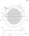
- the Figure 2 shows a top view and a side view of a brand field carrier 5 with the brand field 4, consisting of several, in particular highly symmetrical, brands 1.
- the brand 1 according to Figure 1a is located at the grid position (1, 11) because it is located in the first row and the eleventh column in relation to the shown origin of a coordinate system 6 related to the mark field carrier 5. The counting starts at zero here.
- the mark field 4 is preferably located on a mark field carrier surface 5o of the mark field carrier 5.
- the mark field carrier 5 is preferably transparent, so that the mark field 4 can be detected from a mark field carrier rear side 5r through the mark field carrier 5.
- the mark field carrier 5 preferably has fixing means 12 in the form of vacuum tracks, with the aid of which a substrate 7 (see Figure 8 ) can be fixed.
- the Figure 3 shows a first embodiment of a, in particular transparent, substrate holder 8, which is simultaneously designed as a mark field carrier 5.
- the mark field 4 is then preferably located on the same substrate holder surface 8o as the fixing means 12.
- the substrate holder 5 is non-transparent, wherein the mark field 4 is arranged on the substrate holder rear side 8r.
- the Figure 4 shows a second embodiment of the substrate holder 8'.
- the substrate holder 8' holds the brand field carrier 5, so unlike the first embodiment, it is not itself the brand field carrier.
- the brand field carrier 5 is preferably transparent.
- the brand field 4 is located on the same brand field carrier surface 5o as the fixing means 12.
- the brand field carrier 5 is not supported centrally and can therefore bend downwards, in particular due to gravity, but also due to a force acting from above. Such a bending would compress the brand field 4 on the brand field carrier surface 5o and should therefore preferably be reduced. This is achieved by a particularly thick design of the brand field carrier 5.
- the Figure 5 shows a third, further improved embodiment of the substrate holder 8".
- the substrate holder 8" has struts 10 which support the mark field carrier 5 so that deflection is largely avoided.
- the struts 10 themselves are transparent.
- the Figure 6 shows a fourth, further improved embodiment of the substrate holder 8′′′.
- the substrate holder 8′′′ has struts 10 with, in particular, conical passages 14.
- Individual mark field carriers 5', in particular designed as inserts, which have mark fields 4, can be accommodated or fixed in the passages 14.
- the fixing means 12 are located in this special embodiment, for example, in the substrate holder 8′′′.
- the struts 10 have mark fields 4, so that no marks are provided in the free areas between the struts 10.
- the substrate holder 8′′′ is thus very delicate and light and easy to manufacture. Despite the smaller thickness, it has a high degree of rigidity. Furthermore, the brand field carriers 5' and thus the brand fields 4 can be replaced more easily.
- the Figure 7 shows a fifth, less preferred embodiment of the brand field carrier 5", which here is formed by the substrate 7 itself.
- the substrate 7 has structures 11 on one side (brand field carrier back side 5r") and the brand field 4 on the opposite side. This special embodiment is only useful if it can be ensured that the brand field carrier back side 5r", on which the brand field 4 is located, does not deform.
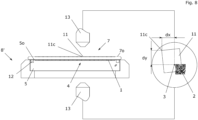
- the Figure 8 shows the substrate holder 8' with the inserted and fixed transparent mark field carrier 5, on which the substrate 7 with structures 11 is fixed by means of the fixing means 12.
- a first, in particular upper, optics 13 captures the substrate surface 70 on which the structures 11 are arranged with a field of view (shown enlarged).
- the first optics 13' are focused on the structures 11.
- a second optic 13' which is particularly calibrated and preferably congruent with the first optic 13, captures the mark field carrier surface 5o with the mark field 4 through the transparent mark field carrier 5.
- the second optic 13' is focused on the marks 2.
- the captured images are superimposed, in particular digitally, and result in an overlay image from which distances dx and dy of one (or more) structural features 11c (here: upper left corner of the structure 11) to the high-precision position mark 3 are determined in relation to an XY coordinate system.
- the corners of the structure 11 are not congruent with the position mark 3, so the distances dx and dy are not equal to zero. Furthermore, the structure 11 is slightly rotated with respect to the reference orientation of the position mark 3.
- the position mark 2 which provides information about the rough position.
- the rotation state and/or a deformation of the structure 11 can be determined.
- Figures 9 to 13 show further recording steps using different case studies, which differ as follows:
- Figure 9 The optical axes of the two optics 13 are congruent to one another.
- the characteristic structural features 11c of the structures 11 are located directly above the position marks 3 relevant for position measurement. Accordingly, an ideal superimposed image is obtained.
- a further feature is that the density of the structures 11 on the substrate surface 7o is identical to the density of the position marks 3 on the mark field carrier surface 5o.
- a mark field carrier 5 is constructed which can be used for different substrates 7 with different densities of structures 11.
- the density of the marks 1 is in particular higher than the density of the structures 11. This ensures that in the area of a Structure 11 and/or a structural feature 11c, at least one mark 1 lies in the field of view of the optics 13, 13'.
- Figure 10 The optical axes of the two optics 13 are congruent to one another.
- the characteristic features 11c of the structures 11 are not located directly above the position marks 3 relevant for position measurement.
- the difference resulting in the overlay image is solely due to the shift between the position marks 3 and the structures 11 and is not based on an optical error.
- a further feature is that the density of the structures 11 on the substrate surface 7o is not identical to the density of the position marks 3 on the mark field carrier surface 5o.
- Figure 11 The optical axes of the two optics 13, 13' are not congruent, not even parallel to each other. It cannot therefore be assumed that the characteristic structural features 11c of a structure 11 are congruent with the respective position mark 3 (even if they lie exactly on top of each other) in the superposition image. The inclination of the optical axes, as well as changes in the thickness of the substrate 7, a wedge error of the substrate 7, etc. lead to the fact that even under ideal conditions the overlay images are not ideal.
- Figure 12 The density of the structures 11 is different from the density of the position marks 3.
- the characteristic structural features 11c are not congruent with the position marks 3 and the optical axes of the optics 3 are neither congruent nor parallel to each other. By eliminating the error resulting from the optical axes, as described in Figure 11 , then an overlay image remains according to Figure 10 .
- Figure 13 This embodiment shows the preferred case according to the invention. Again, the densities of the structures 11 and the position marks 3 are different. The oblique optical axes cause an optical error in the overlay image, which is calculated out by 180° rotation and a second complete measurement of all structures. Furthermore, the structure 11 is located much too far to the left. It is conceivable that the surface was distorted by a process and/or that this part was thermally expanded more strongly due to thermal exposure. The displacement of the structure 11 therefore no longer has anything to do with the global displacement of all structures 11 in relation to the mark field 4, which can be attributed in particular to the fact that the substrate 7 has experienced a displacement as a whole in relation to the mark field 4. This displacement of the structure 11 is location-specific and immanent. It is particularly important that the underlying mark field 4 is and remains highly symmetrical.
- the Figure 14a shows an overlay image of a structure 11 with a position mark 3 and a position mark 2 at a position (11,1) in a rotational position of 0°.
- the distances dx(11,1),0° and dy(11,1),0° between the position mark 3 and the characteristic structural feature 11c of the structure 11 are recorded.
- the Figure 14b shows an overlay image of a structure 11 with a position mark 3 and a position mark 2 at a first position (11,1) in a rotational position of 180°.
- the distances dx(11,1),180° and dy(11,1),180° between the position mark 3 and the characteristic structural feature 11c of the structure 11 are recorded.
- the errors caused by the inclination of the optical axes and other sources of error can be calculated in the x- and y-direction, respectively, so that the pure offset between the position mark 3 and the characteristic feature 11c of the structure 11 can be determined (calculated).
- the Figures 15a and 15b show another structure 11 at a second position (12,1), again in the two different rotation positions of 0° and 180°.
- the errors caused by the inclination of the optical axes and other sources of error can be calculated out in the x- and y-direction.
- the Figures 14 and 15 are intended to illustrate that the horizontal and/or vertical differences between the position marks 3 and the characteristic structural features 11c can vary greatly at different positions. These deviations are primarily the result of distortions, stretching, etc.
- the Figure 16 shows a vector field.
- the vector field describes schematically how the structures 11 (not shown here) are deformed as a function of the location.
- the size of the arrows increases from the center outwards. This indicates that the structures are stretched towards the edge of the substrate 7.
- the length of the arrows increases. This indicates that the translational displacement increases towards the edge. This is therefore a classic run-out error. Since none of the arrows has a tangential component, no rotational deviation was determined. In practice, the vector fields determined according to the invention look more complicated.
- the Figure 17 shows a schematic representation of a section of the image overlay of ideal and real structures and position marks in one position.
- the representation serves to mathematically illustrate the relationship between the different calculable and measurable quantities.
- the exact representation of the position marks is omitted.
- the coordinate axes of the coordinate systems of the ideal and real planes have already been adjusted to each other so that all coordinate systems have the same orientation and the same origin. With the exception of the optical error, which was not explicitly drawn in but is only mentioned in the formula, all other difference vector relationships are recognizable.
- the position of the ideal position mark 3i and the position of the ideal structure 11i are available in the computer.
- the position of the real position mark 3r and the position of the real structure 11r are measured.
- the difference vector r Sr,Mr can be measured.
- the difference vector r Si,Mi can be determined directly from the computer data. No measurement is required here.
- the difference vector r Mr,Mi can also be measured.
- the difference vector r Sr,Si i.e. the deviation of the position of the real structure 11r from the position of the ideal structure 11i, can be calculated from the data obtained.
Landscapes
- Physics & Mathematics (AREA)
- General Physics & Mathematics (AREA)
- Engineering & Computer Science (AREA)
- Multimedia (AREA)
- Length Measuring Devices By Optical Means (AREA)
- Container, Conveyance, Adherence, Positioning, Of Wafer (AREA)
Description
Die vorliegende Erfindung betrifft eine Vorrichtung zur Bestimmung von X-Y-Positionen von Strukturmerkmalen von auf einem Substrat angeordneten Strukturen nach Anspruch 1 sowie ein korrespondierendes Verfahren nach Anspruch 8.The present invention relates to a device for determining X-Y positions of structural features of structures arranged on a substrate according to
In der Industrie ist es von entscheidender Bedeutung, eine Aussage über die Position von Strukturen auf einem Substrat zu erhalten. Von besonderem Interesse ist die Differenz zwischen der realen Ist-Position und der idealen Soll-Position einer Struktur. Um die Ist-Positionen von Strukturen zu bestimmen kann man ein Koordinatensystem einführen und die Position der Strukturen in Bezug zu diesem Koordinatensystem angeben. Meistens handelt es sich dabei um ein körperfestes, d.h. dem Substrat zugeordnetes, Koordinatensystem. Das Koordinatensystem wird im weiteren Verlauf als Substratkoordinatensystem bezeichnet.
Um allerdings alle Strukturen vermessen zu können, muss eine Relativbewegung zwischen dem Substrat und dem Vermessungssystem, insbesondere einem optischen System mit Kamera, erfolgen. Das ist notwendig, da sich nicht alle Strukturen im Sichtbereich des Vermessungssystems befinden. Würden sich alle zu vermessenden Strukturen im Sichtbereich des Vermessungssystems befinden, wäre eine Relativbewegung zwischen dem Vermessungssystem, und dem Substrat natürlich nicht notwendig.However, in order to be able to measure all structures, a relative movement must take place between the substrate and the measuring system, in particular an optical system with a camera. This is necessary because not all structures are in the field of view of the measuring system. If all structures to be measured were in the field of view of the measuring system, a Relative movement between the measuring system and the substrate is of course not necessary.
Die Relativbewegung erfolgt meistens durch eine aktive Bewegung des Substrathalters, auf dem das Substrat fixiert ist, damit das filigrane optische System nicht bewegt werden muss. In diesem Fall muss die Position des Substrathalters sehr genau bestimmt werden, um die Distanzen bestimmen zu können, die der Substrathalter zurückgelegt hat. Die Position des Substrathalters muss also in Bezug zu einem raumfesten Koordinatensystem angegeben werden.The relative movement is usually achieved by an active movement of the substrate holder on which the substrate is fixed so that the delicate optical system does not have to be moved. In this case, the position of the substrate holder must be determined very precisely in order to be able to determine the distances that the substrate holder has covered. The position of the substrate holder must therefore be specified in relation to a spatially fixed coordinate system.
Denkbar wäre auch, nur den zurückgelegten Weg des Substrathalters zwischen zwei Punkten zu bestimmen. In diesem Fall wird zwar auf ein raumfestes Koordinatensystem verzichtet, es wird aber dennoch eine sehr präzise Steuerungsanlage benötigt, um die zurückgelegten Distanzen sehr genau bestimmen zu können.It would also be conceivable to only determine the path traveled by the substrate holder between two points. In this case, a spatially fixed coordinate system is dispensed with, but a very precise control system is still required in order to be able to determine the distances traveled very precisely.
Jede genannte Methode aus dem Stand der Technik benötigt relativ teure und komplizierte elektronisch-mechanische Systeme, um die Position beziehungsweise den zurückgelegten Weg des Substrathalters und damit die Strukturpositionen an der Substratoberfläche eines Substrats vermessen zu können. Des Weiteren sind die Verfahrwege derartiger Anlagen erheblich. Durch die entsprechende Baugröße haben bereits kleinste Temperaturschwankungen einen Einfluss auf die thermischen Dehnungen und damit die Bauteilgrößen der verwendeten Bauteile.Each of the above-mentioned state-of-the-art methods requires relatively expensive and complicated electronic-mechanical systems in order to be able to measure the position or the path covered by the substrate holder and thus the structure positions on the substrate surface of a substrate. Furthermore, the travel distances of such systems are considerable. Due to the corresponding size, even the smallest temperature fluctuations have an influence on the thermal expansion and thus the component sizes of the components used.
Um Strukturen, die sich nicht gleichzeitig im Sichtbereich einer Optik befinden, an der Substratoberfläche eines Substrats vermessen zu können, muss eine Relativbewegung zwischen dem Substrat und der Optik erfolgen, um die Strukturen nacheinander in den Sichtbereich der Optik zu bringen. Meistens verfährt der Substrathalter, auf dem das Substrat fixiert wird, während die Optiken fixiert sind. Während der Fahrt muss die Position des Substrathalters kontinuierlich mitverfolgt werden. Man benötigt also ein Bezugssystem in Bezug zu dem die Position des Substrathalters angegeben wird. Die Positionsangabe des Substrathalters und damit des Substrats muss sehr genau erfolgen, insbesondere im Nanometerbereich. Diese exakte Positionsangabe, insbesondere über Wegstrecken von mehreren Zentimetern, erfordert sehr genaue und somit teure Messsysteme, insbesondere Interferometer.In order to measure structures on the surface of a substrate that are not simultaneously in the field of view of an optic, a relative movement must take place between the substrate and the optic in order to bring the structures into the field of view of the optic one after the other. In most cases, the substrate holder on which the substrate is fixed moves while the optics are fixed. The position of the substrate holder must be continuously monitored during the movement. A reference system is therefore required in relation to which the position of the substrate holder is specified. The position of the substrate holder and thus of the substrate must be specified very precisely, especially in the nanometer range. This exact position specification, especially over distances of several centimeters, requires very precise and therefore expensive measuring systems, especially interferometers.
Aufgabe der vorliegenden Erfindung ist es daher, eine Vorrichtung und ein Verfahren zum Vermessen von Substraten anzugeben, mit dem eine genauere und/oder effizientere Bestimmung der Positionen von Strukturen oder Strukturmerkmalen auf Substraten ermöglicht wird.The object of the present invention is therefore to provide a device and a method for measuring substrates, which enables a more precise and/or more efficient determination of the positions of structures or structural features on substrates.
Diese Aufgabe wird mit den Merkmalen der Ansprüche 1 und 8 gelöst. Vorteilhafte Weiterbildungen der Erfindung sind in den Unteransprüchen angegeben. Der Schutzbereich wird durch die Ansprüche definiert.This object is achieved with the features of
Der Erfindung liegt der Gedanke zugrunde, ein Markenfeld mit
- mindestens zwei Lagemarken mit Informationen zur Lage der jeweiligen Lagemarke im Markenfeld und
- mindestens eine einer der Lagemarken zugeordnete oder zuordenbare Positionsmarke zur Bestimmung von X-Y-Positionen von Strukturmerkmalen von Strukturen auf einem Substrat, insbesondere unabhängig von einer Bewegung oder Position eines Substrathalters vorzusehen.
- at least two location markers with information on the location of the respective location marker in the marker field and
- to provide at least one position mark assigned or assignable to one of the position marks for determining XY positions of structural features of structures on a substrate, in particular independently of a movement or position of a substrate holder.
Die erfindungsgemäße Vermessung der Strukturen eines Substrats erlaubt in weiteren Prozessschritten insbesondere einen genaueren und effizienteren Bondvorgang zweier Substrate zueinander. Entsprechen die vermessenen Strukturpositionen nicht den gewünschten Strukturpositionen erfolgt insbesondere vor und/oder während dem Bondvorgang eine Kompensation mindestens eines der beiden Substrate.The measurement of the structures of a substrate according to the invention allows, in particular, a more precise and efficient bonding process between two substrates in further process steps. If the measured structure positions do not correspond to the desired structure positions, compensation of at least one of the two substrates takes place, in particular before and/or during the bonding process.
Mit anderen Worten werden vorzugsweise Substratpaare nach Auswahlkriterien gebildet.In other words, substrate pairs are preferentially formed according to selection criteria.
Insbesondere wird erfindungsgemäß aus zwei X-Y-Positionen oder aus weiteren Merkmalen der Lagemarken und/oder Positionsmarke(n) eine Lage, insbesondere Rotationslage, der Strukturen bestimmt.In particular, according to the invention, a position, in particular a rotational position, of the structures is determined from two X-Y positions or from further features of the position marks and/or position mark(s).
Weiterhin ist es erfindungsgemäß denkbar, aus zwei X-Y-Positionen oder aus weiteren Merkmalen der Lagemarken und/oder Positionsmarke(n) Dehnungen oder Zerrungen der Strukturen zu bestimmen.Furthermore, it is conceivable according to the invention to determine stretching or straining of the structures from two X-Y positions or from further features of the location marks and/or position mark(s).
Ein, insbesondere eigenständiger, Erfindungsaspekt liegt darin, einzelne X-Y-Positionen von Strukturmerkmalen von Strukturen an der Substratoberfläche eines Substrats mit Positionsmarken auf einer, der Substratoberfläche des Substrats gegenüberlegenden, Oberfläche zu assoziieren beziehungsweise in Relation zu setzen, insbesondere deren Abstände in X- und/oder Y-Richtung zu bestimmen. Dazu werden neben den Positionsmarken insbesondere zusätzlich Lagemarken verwendet. Durch die Verwendung derartiger Positions- und Lagemarken ist es nicht mehr notwendig, die Position des Substrathalters hochpräzise mit technisch aufwendigen, insbesondere optischen, Messsystemen zu bestimmen oder mit zu verfolgen. Eine grobe Bestimmung der aktuellen Position erfolgt insbesondere durch das Auslesen und Interpretieren der Lagemarken. Eine präzisere Bestimmung der aktuellen Position kann insbesondere durch zusätzliche, vorzugsweise den Lagemarken zugeordnete, Positionsmarken erfolgen.One, particularly independent, aspect of the invention is to associate or relate individual XY positions of structural features of structures on the substrate surface of a substrate with position marks on a surface opposite the substrate surface of the substrate, in particular to determine their distances in the X and/or Y direction. In addition to the position marks, additional position marks are used for this purpose. By using such position and position marks, it is no longer necessary to determine or track the position of the substrate holder with high precision using technically complex, in particular optical, measuring systems. A rough determination of the current position is carried out in particular by reading out and interpreting the position marks. A more precise determination of the current position can be achieved in particular by additional position marks, preferably assigned to the position marks.
Die Erfindung beschreibt somit insbesondere eine Methode und eine Vorrichtung zur Bestimmung, insbesondere Vermessung, vorzugsweise Positionsvermessung, von Strukturen oder Strukturmerkmalen, ohne die Position des Substrathalters, und damit die Position des Substrats, relativ zu einem (anderen) Bezugssystem ermitteln zu müssen.The invention thus describes in particular a method and a device for determining, in particular measuring, preferably position measuring, structures or structural features without having to determine the position of the substrate holder, and thus the position of the substrate, relative to a (different) reference system.
Ein weiterer, insbesondere eigenständiger Kern der Erfindung besteht darin, eine Methode und eine Vorrichtung vorzusehen, mit deren Hilfe insbesondere gänzlich auf die Verwendung eines raumfesten Bezugssystems, in Bezug zu dem die X-Y-Position des Substrathalters angegeben beziehungsweise vermessen wird, verzichtet werden kann.A further, particularly independent core of the invention consists in providing a method and a device with the aid of which, in particular, the use of a spatially fixed reference system, in relation to which the X-Y position of the substrate holder is specified or measured, can be completely dispensed with.
Der Grundgedanke besteht insbesondere darin, ein Markenfeld, vorzugsweise an einer Oberfläche, auszubilden, welches der Substratoberfläche, auf der die Strukturen oder Strukturmerkmale vermessen werden sollen, gegenüberliegend angeordnet ist oder anordenbar ist.The basic idea is in particular to form a marking field, preferably on a surface, which is arranged or can be arranged opposite the substrate surface on which the structures or structural features are to be measured.
Das Markenfeld verfügt insbesondere über zwei Eigenschaften: Jede Marke des Markenfelds ist so kodiert, dass ein Messsystem, insbesondere eine Optik, auf die Lage der Marke rückschließen kann. Bei Kenntnis dieser Lage kann die Vorrichtung mittels hochgenauer, vorzugsweise der jeweiligen Lagemarke zugeordnete, Positionsmarken eine hochgenaue Positionsbestimmung durchführen.The mark field has two properties in particular: Each mark in the mark field is coded in such a way that a measuring system, in particular an optical system, can determine the position of the mark. If this position is known, the device can carry out a highly accurate position determination using highly precise position marks, preferably assigned to the respective position mark.
Bei Kenntnis des Markenfeldes und der Verwendung zweier zueinander kalibrierter Optiken, können so die Strukturen/Strukturmerkmale von der Substratoberfläche des zu vermessenden Substrats mit den Marken assoziiert werden und vice versa. Dadurch werden Berechnungen, insbesondere von Abstandsänderungen möglich, ohne dass ein raumfestes äußeres Bezugssystem notwendig wäre.With knowledge of the mark field and the use of two optics calibrated to each other, the structures/structural features of the substrate surface of the substrate to be measured can be compared with the marks and vice versa. This makes calculations, especially of distance changes, possible without the need for a spatially fixed external reference system.
Es werden keine raumfesten Bezugssysteme mehr benötigt, in Bezug zu denen die Position des Substrathalters aufgezeichnet werden müssen. Man muss also nicht mehr die Position des Substrathalters nachverfolgen, weder optisch mit Hilfe von Interferometern noch mechanisch mit Hilfe von Schrittzählern. Es ist daher in Weiterbildung der Erfindung vorgesehen, dass, insbesondere über die nachfolgend beschriebenen erfindungsgemäß offenbarten Mittel hinaus keine Mittel zur, insbesondere laufenden, Erfassung der Position des Substrathalters verwendet werden oder vorrichtungsgemäß installiert sind.There is no longer a need for spatially fixed reference systems in relation to which the position of the substrate holder must be recorded. It is therefore no longer necessary to track the position of the substrate holder, either optically using interferometers or mechanically using pedometers. In a further development of the invention, it is therefore provided that, in particular beyond the means disclosed according to the invention described below, no means for, in particular continuously, detecting the position of the substrate holder are used or installed in accordance with the device.
Ein wesentlicher weiterer Aspekt der vorliegenden Erfindung besteht insbesondere darin, Verzerrungen des Markenfeldes und/oder der Positionsmarken zu reduzieren beziehungsweise weitestgehend zu vermeiden.A further essential aspect of the present invention consists in particular in reducing or largely avoiding distortions of the mark field and/or the position marks.
Unter einer Marke wird erfindungsgemäß im weitesten Sinne eine optisch erfassbare und/oder topographisch erfassbare Struktur (oder Strukturmerkmale der Struktur) verstanden, die beziehungsweise deren Position, vorzugsweise zumindest deren X-Y-Position, mit Hilfe eines Messinstruments detektiert und somit bestimmt werden kann. Messinstrumente zur Erfassung der Strukturen/Strukturmerkmale und somit Bestimmung deren Position können insbesondere sein:
- Optische Systeme, insbesondere Kameras
- Kontaktierende Systeme, insbesondere AFM.
- Optical systems, especially cameras
- Contacting systems, especially AFM.
Eine Marke besteht vorzugsweise aus mindestens einem der nachfolgend aufgeführten Materialien:
- ∘ Metall, insbesondere
- ∘ Cr, Al, Ti, Cu, Ag, Au, Fe, Ni, Co, Pt, W, Pb, Ta, Zn, Sn,
- o Legierung, insbesondere
- o Metalllegierung,
- ∘ Metall-Nichtmetalllegieruiig,
- ∘ Keramik,
- o Kunststoff,
- o Halbleiter, insbesondere
- o Verbindungshalbleiter, insbesondere
- ▪ GaAs, GaN, InP, InxGal-xN ,InSb, InAs, GaSb, AIN, InN, GaP, BeTe, ZnO, CuInGaSe2, ZnS, ZnSe, ZnTe, CdS, CdSe, CdTe, Hg(1-x)Cd(x)Te, BeSe, HgS, AlxGal-xAs, GaS, GaSe, GaTe, InS, InSe, InTe, CuInSe2, CuInS2, CuInGaS2, SiC, SiGe,
- o Halbleiter, insbesondere
- ▪ Ge, Si, Alpha-Sn, Fullerene, B, Se, Te.
- o Verbindungshalbleiter, insbesondere
- ∘ Metal, especially
- ∘ Cr, Al, Ti, Cu, Ag, Au, Fe, Ni, Co, Pt, W, Pb, Ta, Zn, Sn,
- o Alloy, especially
- o Metal alloy,
- ∘ Metal-non-metal alloys,
- ∘ Ceramics,
- o plastic,
- o Semiconductors, especially
- o Compound semiconductors, in particular
- ▪ GaAs, GaN, InP, InxGal-xN ,InSb, InAs, GaSb, AIN, InN, GaP, BeTe, ZnO, CuInGaSe2, ZnS, ZnSe, ZnTe, CdS, CdSe, CdTe, Hg(1-x)Cd(x)Te, BeSe, HgS, AlxGal-xAs, GaS, GaSe, GaTe, InS, InSe, InTe, CuInSe2, CuInS2, CuInGaS2, SiC, SiGe,
- o Semiconductors, especially
- ▪ Ge, Si, Alpha-Sn, Fullerenes, B, Se, Te.
- o Compound semiconductors, in particular
Vorzugsweise werden die Marken optisch detektiert, daher werden nachfolgend optische Vermessungen beschrieben. Eine Marke besteht insbesondere aus einer Lagemarke und einer Positionsmarke. Lagemarken sind erfindungsgemäß vorzugsweise kodierbare oder kodierte Marken, also Informationsträger. Positionsmarken werden, insbesondere ausschließlich, für die Bestimmung einer hochgenauen Position, insbesondere X-Y-Position, verwendet.The marks are preferably detected optically, so optical measurements are described below. A mark consists in particular of a location mark and a position mark. According to the invention, location marks are preferably encodable or coded marks, i.e. information carriers. Position marks are used, in particular exclusively, for determining a highly precise position, in particular an X-Y position.
Insbesondere sind die Lagemarke und eine der Lagemarke zugeordnete Positionsmarke gleichzeitig im Sichtbereich der jeweils verwendeten Optik erfassbar. Vorzugsweise ist die Lagemarke, insbesondere jede Lagemarke, in der näheren Umgebung der zugeordneten Positionsmarke angeordnet, damit die gleichzeitige Erfassung sichergestellt wird.In particular, the position mark and a position mark associated with the position mark can be detected simultaneously in the field of view of the respective optics used. Preferably, the position mark, in particular each position mark, arranged in the immediate vicinity of the assigned position mark to ensure simultaneous detection.
Denkbar ist es gemäß einer vorteilhaften Ausführungsform der Erfindung, dass die Lagemarke eine oder mehrere Positionsmarken aufweist.According to an advantageous embodiment of the invention, it is conceivable that the location mark has one or more position marks.
Die Lagemarken sind insbesondere kleiner als 5mm x 5mm, vorzugsweise kleiner als 1mm x 1mm, noch bevorzugter kleiner als 0.1mm x 0.1mm, am bevorzugtesten kleiner als 0.01mm × 0.01mm, am allerbevorzugtesten kleiner als 0.001mm x 0.001mm. Besonders bevorzugt weisen die Lagemarken eine Breite oder einen Durchmesser zwischen 20µm und 200µm auf.The position marks are in particular smaller than 5mm x 5mm, preferably smaller than 1mm x 1mm, even more preferably smaller than 0.1mm x 0.1mm, most preferably smaller than 0.01mm × 0.01mm, most preferably smaller than 0.001mm x 0.001mm. The position marks particularly preferably have a width or diameter between 20µm and 200µm.
Die Positionsmarken sind insbesondere kleiner als 0.1mm × 0.1mm, vorzugsweise kleiner als 0.01mm × 0.01mm, noch bevorzugter kleiner als 0.001mm x 0.001mm, am bevorzugtesten kleiner als 0.0001mm x 0.0001mm, am allerbevorzugtesten kleiner als 0.00001mm x 0.00001 mm.The position marks are in particular smaller than 0.1mm × 0.1mm, preferably smaller than 0.01mm × 0.01mm, even more preferably smaller than 0.001mm x 0.001mm, most preferably smaller than 0.0001mm x 0.0001mm, most preferably smaller than 0.00001mm x 0.00001mm.
Die Lage- und/oder die Positionsmarken sind vorzugsweise Teile eines im Computer erzeugten Musters. Die Positionen der Lage und Positionsmarken im digitalen Muster sind als ideal anzusehen. Durch die Herstellung der Lage- und Positionsmarken, insbesondere mittels Schicht-, Masken- Ätz-und Entwicklungstechniken entstehen die realen Lage- und Positionsmarken. Die Positionen dieser realen Lage- und Positionsmarken werden, insbesondere auf Grund der fehlerbehafteten Prozesse und Anlagen, von der gewünschten Idealposition abweichen. Diese Abweichungen sind vorzugsweise minimal und liegen im Nanometerbereich. Die Genauigkeit der Lage- und Positionsmarken ist daher umso größer, je weniger die Idealpositionen von den Realpositionen abweichen. Die Abweichungen sind insbesondere kleiner als 1µm, vorzugsweise kleiner als 500nm, noch bevorzugter kleiner als 250nm, am bevorzugtesten kleiner als 50nm, am allerbevorzugtesten kleiner als 10nm.The position and/or position marks are preferably parts of a pattern generated in the computer. The positions of the position and position marks in the digital pattern are to be regarded as ideal. The real position and position marks are created by producing the position and position marks, in particular by means of layer, mask, etching and development techniques. The positions of these real position and position marks will deviate from the desired ideal position, in particular due to faulty processes and systems. These deviations are preferably minimal and lie in the nanometer range. The accuracy of the position and position marks is therefore greater the less the ideal positions deviate from the real positions. The deviations are in particular smaller than 1µm, preferably smaller than 500nm, even preferably less than 250nm, most preferably less than 50nm, most preferably less than 10nm.
Ein weiterer Aspekt der Erfindung besteht darin, Fertigungsungenauigkeiten des Markenfeldträgers, insbesondere der Marken, vor allem der eigentlich hochgenau herzustellenden Positionsmarken, in Kauf zu nehmen. Die Vorrichtung weist demnach insbesondere ein Markenfeld auf, dessen Positionsmarken nicht hochpräzise gefertigt wurden, wodurch Produktionskosten erheblich gesenkt werden können.A further aspect of the invention is to accept manufacturing inaccuracies of the mark field carrier, in particular of the marks, especially of the position marks that are actually to be manufactured with high precision. The device therefore has in particular a mark field whose position marks were not manufactured with high precision, which can significantly reduce production costs.
Um dennoch auf ein Positionsmarkenfeld zurückgreifen zu können, das über hochpräzise Positionen verfügt, wird ein Sollpositionsmarkenfeld, insbesondere in einem Computer gespeichert, hinterlegt. Die Positionen der Positionsmarken im Computer sind als ideal anzusehen, während die tatsächlichen Positionen des hergestellten Positionsmarkenfeldes (Ist-Positionen) hiervon abweichen können. In einem Justierprozess wird das Markenfeld des Markenfeldträgers vermessen (Ermittlung der Ist-Positionen) und die Relativpositionen zwischen den idealen Positionsmarken im Computer und den realen Positionsmarken auf dem Markenfeldträger ermittelt und gespeichert.In order to be able to use a position mark field that has highly precise positions, a target position mark field is stored, in particular in a computer. The positions of the position marks in the computer are to be regarded as ideal, while the actual positions of the produced position mark field (actual positions) can deviate from this. In an adjustment process, the mark field of the mark field carrier is measured (determination of the actual positions) and the relative positions between the ideal position marks in the computer and the real position marks on the mark field carrier are determined and stored.
Hieraus wird zu jeder realen Positionsmarke eine entsprechende Korrektur in Bezug zur idealen Positionsmarke berechnet, insbesondere in Form eines auf die jeweilige Position bezogenen Vektors. Mit dieser Methode ist es möglich, die Strukturen auf dem Substrat mit den realen Positionsmarken auf dem Markenfeldträger und diese wiederum mit den idealen Positionsmarken im Computer zu korrelieren. Durch diese Idee lassen sich die Fertigungskosten des Markenfeldträgers, insbesondere durch eine ungenauere Herstellung des Markenfeldes, immens senken und führen so zu einem wirtschaftlichen Vorteil.From this, a corresponding correction is calculated for each real position mark in relation to the ideal position mark, in particular in the form of a vector related to the respective position. This method makes it possible to correlate the structures on the substrate with the real position marks on the mark field carrier and these in turn with the ideal position marks in the computer. This idea allows the manufacturing costs of the mark field carrier to be reduced immensely, in particular by making the mark field less precise, thus leading to an economic advantage.
Erfindungsgemäß ist jede Lagemarke in einem Markenfeld individualisiert. Durch die Individualisierung ist eine Verwechslung unterschiedlicher Lagemarken ausgeschlossen, so dass durch die Erfassung jeder Lagemarke auf einen X-Y-Koordinatenbereich der Lagemarke auf dem Markenfeld geschlossen werden kann. Das Koordinatensystem des Markenfeldes wird insbesondere als Markenfeldkoordinatensystem bezeichnet.According to the invention, each position mark in a mark field is individualized. The individualization prevents confusion between different position marks, so that by recording each position mark, an X-Y coordinate range of the position mark on the mark field can be determined. The coordinate system of the mark field is referred to in particular as the mark field coordinate system.
Bei der Lagemarke handelt es sich vorzugsweise um eine oder mehrere der folgenden Ausprägungen:
- QR Code,
- Strichcode,
- Geometrische, insbesondere dreidimensionale, Figur,
- Zeichenfolge, insbesondre Buchstabenfolge und/oder Zahlenfolge, vorzugsweise Binärcode,
- Bild.
- QR-Code,
- Barcode,
- Geometric, especially three-dimensional, figure,
- Character string, in particular letter sequence and/or number sequence, preferably binary code,
- Picture.
Die Lagemarke ist insbesondere ein Informationsträger. Vorzugsweise wird jede Lagemarke mit einer X-Y-Position codiert, die angibt, an welcher Position im Raster sich die Lagemarke befindet, also in welchem X-Y-Koordinatenbereich die Lagemarke verortet ist.The position marker is in particular an information carrier. Preferably, each position marker is coded with an X-Y position that indicates the position in the grid where the position marker is located, i.e. in which X-Y coordinate range the position marker is located.
Die Positionsmarken können als einfache oder komplexe Gebilde konstruiert sein. Auf die genaue Form der Positionsmarken wird nicht näher eingegangen, da diese im Stand der Technik als solche bekannt sind. In den Figuren werden die Positionsmarken insbesondere als Kreuz dargestellt. Positionsmarken werden vorzugsweise gleich gefertigt und sehen vorzugsweise gleich aus, wie die im Stand der Technik sehr gebräuchlichen Ausrichtungsmarken. Damit können die Techniken, die aus dem Stand der Technik für die Analyse von Ausrichtungsmarken Verwendung finden auch für die Analyse der Positionsmarken verwendet werden.The position marks can be constructed as simple or complex structures. The exact shape of the position marks will not be discussed in detail, as these are known as such in the prior art. In the figures, the position marks are shown in particular as a cross. Position marks are preferably manufactured in the same way and preferably look the same as the alignment marks that are very common in the prior art. This means that the techniques that are used in the prior art for the analysis of alignment marks can also be used for the analysis of the position marks.
In ganz besonderes bevorzugten erfindungsgemäßen Ausführungsformen umgibt, insbesondere umschließt, die Positionsmarke die Lagemarke. In diesem Fall ist die Positionsmarke insbesondere als Kreis, Rechteck, Oktagon oder eine beliebige andere geometrische Figur, die leicht von einer Software erkannt und ausgewertet werden kann, ausgeführt.In particularly preferred embodiments according to the invention, the position mark surrounds, in particular encloses, the position mark. In this case, the position mark is in particular designed as a circle, rectangle, octagon or any other geometric figure that can be easily recognized and evaluated by software.
Das Markenfeld besteht insbesondere aus einer Menge von, vorzugsweise hochsymmetrisch zueinander angeordneten Marken, d.h. Lage- und Positionsmarken, erfindungsgemäß bedeutend ist vor allem, dass die Positionsmarken zueinander hochpräzise hergestellt werden. Die einer Positionsmarke zugeordnete oder zuordenbare Lagemarke wird so angeordnet, dass sich beide vorzugsweise gleichzeitig im Sichtbereich der Optik befinden. Die Lagemarke dient, insbesondere ausschließlich, dem Auslesen der ungefähren Lageposition, im weiteren Verlauf des Textes nur mehr als Lage bezeichnet, welche von der Optik beobachtet wird. Vorzugsweise ist die Relativposition zwischen jeder Lagemarke und der zugeordneten Positionsmarke identisch. Das erleichtert die Programmierung eines Auswertealgorithmus und somit das Aufsuchen der Lage- und/oder Positionsmarken im Markenfeld, sobald sich beide im Sichtbereich der Optik befinden.The mark field consists in particular of a set of marks, preferably arranged highly symmetrically to one another, i.e. location and position marks. What is particularly important according to the invention is that the position marks are manufactured with high precision in relation to one another. The location mark assigned or assignable to a position mark is arranged in such a way that both are preferably in the field of view of the optics at the same time. The location mark serves, in particular, exclusively to read out the approximate location position, referred to in the text only as the position, which is observed by the optics. Preferably, the relative position between each location mark and the assigned position mark is identical. This facilitates the programming of an evaluation algorithm and thus the search for the location and/or position marks in the mark field as soon as both are in the field of view of the optics.
In einer ganz besonders bevorzugten Ausführungsform wird die Lagemarke von der Positionsmarke, insbesondere vollumfänglich, umgeben, insbesondere umschlossen.In a particularly preferred embodiment, the location mark is surrounded, in particular enclosed, by the position mark, in particular completely.
Somit kann die Fertigungsgenauigkeit der Lagemarken geringer sein als die der Positionsmarken, wodurch die Herstellungskosten für das Markenfeld minimiert werden.Thus, the manufacturing accuracy of the location marks can be lower than that of the position marks, which minimizes the manufacturing costs for the mark field.
Sollte das Markenfeld aus Marken bestehen, bei denen die Lagemarke und die Positionsmarke miteinander verschmelzt wurden, werden vorzugsweise alle Marken des Markenfeldes hochpräzise hergestellt, da jede Marke gleichzeitig Lagemarke und Positionsmarke ist, also beide Funktionen aufweist.If the mark field consists of marks in which the location mark and the position mark have been merged, it is preferable to produce all marks in the mark field with high precision, since each mark is both a location mark and a position mark, i.e. it has both functions.
Vorzugsweise sind die Marken in einem, insbesondere symmetrischen, Raster mit einheitlichen Abständen zwischen den Lagemarken angeordnet. Die benachbarten Lagemarken und/oder Positionsmarken sind vorzugsweise äquidistant auf dem Markenfeld angeordnet. In einem Markenfeld befinden sich insbesondere mehr als 10 x 10 Marken, vorzugsweise mehr als 100 x 100 Marken, noch bevorzugter mehr als 1000 x 1000 Marken, am bevorzugtesten mehr als 10000 x 10000 Marken, am allerbevorzugtesten mehr als 100000 x 100000 Marken. Abstände zwischen benachbarten Lagemarken sind insbesondere kleiner als die Breite und/oder Höhe oder der Durchmesser der Lagemarken. Vorzugsweise ist das Verhältnis zwischen dem Abstand und der Breite und/oder Höhe oder dem Durchmesser der Lagemarken kleiner als 1, noch bevorzugter kleiner als 0.5, noch bevorzugter kleiner als 0.1.The marks are preferably arranged in a grid, in particular a symmetrical one, with uniform distances between the position marks. The adjacent position marks and/or position marks are preferably arranged equidistantly on the mark field. In a mark field there are in particular more than 10 x 10 marks, preferably more than 100 x 100 marks, even more preferably more than 1000 x 1000 marks, most preferably more than 10000 x 10000 marks, most preferably more than 100000 x 10000 marks, most preferably more than 100000 x 100000 marks. Distances between adjacent position marks are in particular smaller than the width and/or height or the diameter of the position marks. Preferably, the ratio between the distance and the width and/or height or the diameter of the position marks is smaller than 1, even more preferably smaller than 0.5, even more preferably smaller than 0.1.
Vorzugsweise kodieren die Lagemarken die X-Y-Position im Raster. Dadurch ist es möglich, bei Erfassung der Lagemarke auf den jeweiligen Rasterbereich zu schließen, der von den Erfassungsmitteln, insbesondere einer oder mehreren Optiken, gerade erfasst wird. Denkbar ist die Kodierung zusätzlicher Informationen in jeder Lagemarke, beispielsweise die Lage der zugeordneten Positionsmarke zur Lagemarke.Preferably, the position marks encode the X-Y position in the grid. This makes it possible to determine the respective grid area that is currently being recorded by the recording means, in particular one or more optics, when the position mark is recorded. It is conceivable to encode additional information in each position mark, for example the position of the associated position mark for the position mark.
Der Vollständigkeit halber wird offenbart, dass sich die Marken nicht auf einem hochsymmetrischen Raster befinden müssen. Die Verteilung der Marken kann beliebig sein, solange die Abstandbeziehungen (Vektoren oder X-Y-Abstände) zwischen den Positionsmarken bekannt und die jeweiligen Lagemarken mit ihren entsprechenden Positionsmarken assoziierbar sind. Eine Verteilung der Marken auf einem nicht symmetrischen Raster stellt eine verschlechterte Ausführungsform dar.For the sake of completeness, it is disclosed that the marks do not have to be on a highly symmetrical grid. The distribution of the marks can be arbitrary, as long as the distance relationships (vectors or XY distances) between the position marks are known and the respective Location marks can be associated with their corresponding position marks. A distribution of the marks on a non-symmetrical grid represents a deteriorated embodiment.
Das Markenfeld wird vorzugsweise einerseits so nahe wie möglich an der Substratoberfläche angeordnet, an der sich die Strukturen befinden, die vermessen werden sollen beziehungsweise deren X-Y-Positionen erfindungsgemäß bestimmt werden. Andererseits sollen die Strukturen, die das Markenfeld bilden, vor Beschädigungen geschützt werden.On the one hand, the marking field is preferably arranged as close as possible to the substrate surface on which the structures are located that are to be measured or whose X-Y positions are to be determined according to the invention. On the other hand, the structures that form the marking field should be protected from damage.
Der Abstand zwischen den zu vermessenden Strukturen und dem Markenfeldträger liegt vorzugsweise zwischen 0.1mm und 100mm, vorzugsweise zwischen 0.25mm und 75mm, noch bevorzugter zwischen 0.5mm und 50mm, am bevorzugtesten zwischen 1mm und 30mm, am allerbevorzugtesten zwischen 5mm und 20mm.The distance between the structures to be measured and the mark field carrier is preferably between 0.1mm and 100mm, preferably between 0.25mm and 75mm, more preferably between 0.5mm and 50mm, most preferably between 1mm and 30mm, most preferably between 5mm and 20mm.
Insbesondere wird das Markenfeld an der dem Substrat abgewandten Seite des Markenfeldträgers angeordnet, um es vor mechanischer Belastung und Abrieb zu schützen, da es auf diese Weise nicht direkt mit dem Substrat in Kontakt kommt. Denkbar ist auch, dass das Markenfeld mit einer transparenten Beschichtung überzogen wird, um es vor mechanischen und/oder chemischen Einflüssen zu schützen.In particular, the brand field is arranged on the side of the brand field carrier facing away from the substrate in order to protect it from mechanical stress and abrasion, as it does not come into direct contact with the substrate in this way. It is also conceivable that the brand field is covered with a transparent coating in order to protect it from mechanical and/or chemical influences.
Ein erfindungsgemäßer Markenfeldträger ist das oder sind die Bauteile, auf denen ein Markenfeld aufgebracht ist/wird.A brand field carrier according to the invention is the component or components on which a brand field is/will be applied.
Gemäß einer ersten erfindungsgemäßen Ausführungsform ist der Substrathalter selbst der Markenfeldträger. Das Markenfeld befindet sich auf einer der beiden Oberflächen des Substrathalters, vorzugsweise auf der Fixieroberfläche, auf der das Substrat fixiert wird.According to a first embodiment of the invention, the substrate holder itself is the mark field carrier. The mark field is located on one of the two surfaces of the substrate holder, preferably on the fixing surface on which the substrate is fixed.
Befindet sich das Markenfeld auf der Fixieroberfläche, wird der Substrathalter zumindest unterhalb des Markenfeldes vorzugsweise zumindest teilweise transparent ausgebildet in Bezug auf die elektromagnetische Strahlung, mit der das Markenfeld beobachtet wird.If the mark field is located on the fixing surface, the substrate holder is preferably designed to be at least partially transparent at least below the mark field with respect to the electromagnetic radiation with which the mark field is observed.
Befindet sich das Markenfeld auf der, der Fixieroberfläche gegenüberliegenden, Oberfläche, kann der Substrathalter auch intransparent sein.If the marking field is located on the surface opposite the fixing surface, the substrate holder can also be non-transparent.
In einer zweiten, besonders bevorzugten erfindungsgemäßen Ausführungsform handelt es sich bei dem Markenfeldträger um ein eigenständiges Bauteil, welches in oder an dem Substrathalter fixierbar ist und damit schnell ausgetauscht werden kann.In a second, particularly preferred embodiment according to the invention, the mark field carrier is an independent component which can be fixed in or on the substrate holder and can thus be quickly replaced.
Vorzugsweise ist auch in diesem Fall das Markenfeld an der Fixieroberfläche angebracht und das Bauteil zumindest teilweise transparent für die verwendete elektromagnetische Strahlung. Durch diese Ausführung kann der Markenfeldträger vom Substrathalter getrennt hergestellt werden. Hierdurch wird die Flexibilität erhöht und ein Austausch erleichtert. Weiterhin können die Produktionskosten gesenkt werden.Preferably, in this case too, the mark field is attached to the fixing surface and the component is at least partially transparent to the electromagnetic radiation used. This design allows the mark field carrier to be manufactured separately from the substrate holder. This increases flexibility and makes replacement easier. Furthermore, production costs can be reduced.
Gemäß einer erfindungsgemäßen Erweiterung wird der Substrathalter so konstruiert, dass der Markenfeldträger in diesen einsetzbar ist und ausschließlich peripher unterstützt wird. In dieser besonderen Ausführungsform wird der Markenfeldträger möglichst dick konstruiert, sodass der Biegewiderstand möglichst groß ist und eine Verzerrung der Positionsmarken minimiert wird, vorzugsweise gänzlich entfällt. Der nur peripher gestützte Markenfeldträger wird durch die Gravitationskraft umso stärker durchgebogen, je dünner er ausgebildet ist. Die Durchbiegung führt zu einer Streckung der Markenfeldträgeroberfläche, die in Richtung der Gravitation zeigt. Folglich würde auch das Markenfeld gestaucht werden, wodurch die Qualität der Bestimmung der X-Y-Positionen sinkt.According to an extension according to the invention, the substrate holder is designed in such a way that the mark field carrier can be inserted into it and is only supported peripherally. In this particular embodiment, the mark field carrier is designed to be as thick as possible so that the bending resistance is as high as possible and distortion of the position marks is minimized, preferably completely eliminated. The mark field carrier, which is only supported peripherally, is bent more strongly by the force of gravity the thinner it is designed. The bending leads to a stretching of the mark field carrier surface, which is directed in the direction of the Gravity. Consequently, the marker field would also be compressed, which would reduce the quality of the determination of the XY positions.
Gemäß einer anderen erfindungsgemäßen Erweiterung wird der Substrathalter so konstruiert, dass der Markenfeldträger in den Substrathalter eingesetzt werden kann und nicht nur peripher, sondern durch, insbesondere im Zentrum zusammenlaufende, Streben auch von unten unterstützt wird. Die Streben minimieren vor allem eine Durchbiegung des Markenfeldträgers. Vorzugsweise sind die Streben zumindest teilweise transparent für die bei der Erfassung der X-Y-Position der Strukturen verwendete elektromagnetische Strahlung. Sind die Streben intransparent, kann entlang der durch die Streben verdeckten Fläche keine Korrelation zwischen den Marken des Markenfeldes und den Strukturen auf der Substratoberfläche hergestellt werden.According to another extension of the invention, the substrate holder is designed in such a way that the mark field carrier can be inserted into the substrate holder and is supported not only peripherally but also from below by struts that converge in particular in the center. The struts primarily minimize deflection of the mark field carrier. Preferably, the struts are at least partially transparent to the electromagnetic radiation used to detect the X-Y position of the structures. If the struts are non-transparent, no correlation can be established between the marks of the mark field and the structures on the substrate surface along the area covered by the struts.
Der Transmissionsgrad des Markenfeldhalters und/oder der Streben ist insbesondere größer als 10%, vorzugsweise größer als 25%, noch bevorzugter größer als 50%, am bevorzugtesten größer als 75%, am allerbevorzugtesten größer als 95%.The transmittance of the brand field holder and/or the struts is in particular greater than 10%, preferably greater than 25%, even more preferably greater than 50%, most preferably greater than 75%, most preferably greater than 95%.
Dem Problem der Durchbiegung kann vor allem mit einem möglichst dicken Markenfeldträger entgegengewirkt werden. Die Dicke des Markenfeldträgers ist insbesondere größer als 1mm, vorzugsweise größer als 2mm, noch bevorzugter größer als 5mm, am bevorzugtesten größer als 20mm, am allerbevorzugtesten größer als 30mm. Je dicker der Markenfeldträger ist, desto größer ist sein Biegewiderstand und desto weniger stark kann der Markenfeldträger durch Biegung verformt werden.The problem of deflection can be counteracted primarily by using a brand field carrier that is as thick as possible. The thickness of the brand field carrier is in particular greater than 1mm, preferably greater than 2mm, even more preferably greater than 5mm, most preferably greater than 20mm, most preferably greater than 30mm. The thicker the brand field carrier, the greater its bending resistance and the less the brand field carrier can be deformed by bending.
Die Substrate können jede beliebige Form besitzen, sind aber bevorzugt kreisrund. Der Durchmesser der Substrate ist insbesondere industriell genormt. Für Wafer sind die industrieüblichen Durchmesser, 1 Zoll, 2 Zoll, 3 Zoll, 4 Zoll, 5 Zoll, 6 Zoll, 8 Zoll, 12 Zoll und 18 Zoll. Die erfindungsgemäße Ausführungsform kann aber grundsätzlich jedes Substrat, unabhängig von dessen Durchmesser handhaben.The substrates can have any shape, but are preferably circular. The diameter of the substrates is particularly standardized industrially. For wafers, the industry-standard diameters are 1 inch, 2 inches, 3 inches, 4 inches, 5 inches, 6 inches, 8 inches, 12 inches and 18 inches. However, the embodiment according to the invention can basically handle any substrate, regardless of its diameter.
Der Markenfeldträger und/oder das Markenfeld weisen einen Durchmesser und/oder eine Umfangskontur auf, der insbesondere dem Durchmesser des Substrats weitgehend entspricht.The brand field carrier and/or the brand field have a diameter and/or a circumferential contour which largely corresponds in particular to the diameter of the substrate.
In besonderen Ausführungsformen ist der Durchmesser des Markenfeldträgers größer als der des Substrates, insbesondere größer als 1.01 mal, vorzugsweise größer als 1.05 mal, noch bevorzugter größer als 1.1 mal, am bevorzugtesten größer als 1.2 mal, am allerbevorzugtesten größer als 1.2 mal der Durchmesser des Substrats.In particular embodiments, the diameter of the mark field carrier is larger than that of the substrate, in particular larger than 1.01 times, preferably larger than 1.05 times, even more preferably larger than 1.1 times, most preferably larger than 1.2 times, most preferably larger than 1.2 times the diameter of the substrate.
Gemäß einer erfindungsgemäßen Weiterbildung sind die Streben möglichst transparent. Vorzugsweise werden die Streben selbst aus einem Material gefertigt, das vollkommen transparent für die verwendete elektromagnetische Strahlung ist. Denkbar ist auch, die Streben so weit wie möglich mit Nuten und Löchern zu versehen, um möglichst viele Sichtbereiche für die verwendete Optik zu schaffen. Die Nuten und Löcher können, insbesondere formschlüssig und/oder bündig, mit transparenten Einsätzen verschlossen werden, um die redezierte Stützwirkung wieder zu erhöhen.According to a further development of the invention, the struts are as transparent as possible. Preferably, the struts themselves are made of a material that is completely transparent to the electromagnetic radiation used. It is also conceivable to provide the struts with as many grooves and holes as possible in order to create as many viewing areas as possible for the optics used. The grooves and holes can be closed with transparent inserts, in particular in a form-fitting and/or flush manner, in order to increase the reduced support effect again.
Der Markenfeldträger wird vorzugsweise aus mindestens einem der folgenden Materialien, zumindest teilweise, gefertigt
- Metall, insbesondere
- ∘ Cu, Ag, Au, Al, Fe, Ni, Co, Pt, W, Cr, Pb, Ti, Ta, Zn, Sn und/oder
- Kunststoff, insbesondere
- ∘ Elastomere, insbesondere
- ▪ Viton (Werkstoff) und/oder
- ▪ Polyurethane und/oder
- ▪ Hypalon (Werkstoff) und/oder
- ▪ Isopren-Kautschuk (Werkstoff) und/oder
- ▪ Nitril-Kautschuk (Werkstoff) und/oder
- ▪ Perfluorokautschuk (Werkstoff) und/oder
- ▪ Polyisobuten (Werkstoff),
- ∘ Thermoplastische Elastomere und/oder
- ∘ Elastomere, insbesondere
- Halbleitermaterial, insbesondere
- ∘ Verbindungshalbleiter
- ▪ GaAs, GaN, InP, InxGal-xN ,InSb, InAs, GaSb, AIN, InN, GaP, BeTe, ZnO, CuInGaSe2, ZnS, ZnSe, ZnTe, CdS, CdSe, CdTe, Hg(1-x)Cd(x)Te, BeSe, HgS, AlxGal-xAs, GaS, GaSe, GaTe, InS, InSe, InTe, CuInSe2, CuInS2, CuInGaS2, SiC, SiGe
- ∘ Halbleiter, insbesondere
- ▪ Ge, Si, Alpha-Sn, Fullerene, B, Se, Te
- ∘ Verbindungshalbleiter
- Glas, insbesondere
- ∘ Metallische Gläser
- ∘ Nichtmetallische Gläser, insbesondere
- ▪ Organische nichtmetallische Gläser
- ▪ Anorganische nichtmetallische Gläser, insbesondere
- Nichtoxidische Gläser, insbesondere
- ∘ Halogenidgläser
- ∘ Chalkogenidgläser
- Oxidische Gläser, insbesondere
- ∘ Phosphatische Gläser
- ∘ Silikatische Gläser, insbesondere
- ▪ Alumosilikatgläser
- ▪ Bleisilikatgläser
- ▪ Alkali-Silikatgläser, insbesondere
- • Alkali-Erdalkalisilikatgläser
- ▪ Borosilikatgläser
- ∘ Boratgläser, insbesondere
- ▪ Alkaliboratgläser
- ∘ Quarz
- Nichtoxidische Gläser, insbesondere
- Keramik
- Mineralien, insbesondere Saphir.
- Metal, especially
- ∘ Cu, Ag, Au, Al, Fe, Ni, Co, Pt, W, Cr, Pb, Ti, Ta, Zn, Sn and/or
- Plastic, especially
- ∘ Elastomers, especially
- ▪ Viton (material) and/or
- ▪ Polyurethanes and/or
- ▪ Hypalon (material) and/or
- ▪ Isoprene rubber (material) and/or
- ▪ Nitrile rubber (material) and/or
- ▪ Perfluoro rubber (material) and/or
- ▪ Polyisobutene (material),
- ∘ Thermoplastic elastomers and/or
- ∘ Elastomers, especially
- Semiconductor material, in particular
- ∘ Compound semiconductors
- ▪ GaAs, GaN, InP, InxGal-xN ,InSb, InAs, GaSb, AIN, InN, GaP, BeTe, ZnO, CuInGaSe2, ZnS, ZnSe, ZnTe, CdS, CdSe, CdTe, Hg(1-x)Cd(x)Te, BeSe, HgS, AlxGal-xAs, GaS, GaSe, GaTe, InS, InSe, InTe, CuInSe2, CuInS2, CuInGaS2, SiC, SiGe
- ∘ Semiconductors, especially
- ▪ Ge, Si, Alpha-Sn, Fullerenes, B, Se, Te
- ∘ Compound semiconductors
- Glass, especially
- ∘ Metallic glasses
- ∘ Non-metallic glasses, especially
- ▪ Organic non-metallic glasses
- ▪ Inorganic non-metallic glasses, in particular
- Non-oxide glasses, especially
- ∘ Halide glasses
- ∘ Chalcogenide glasses
- Oxidic glasses, especially
- ∘ Phosphatic glasses
- ∘ Silicate glasses, especially
- ▪ Aluminosilicate glasses
- ▪ Lead silicate glasses
- ▪ Alkali-silicate glasses, especially
- • Alkali-alkaline earth silicate glasses
- ▪ Borosilicate glasses
- ∘ Borate glasses, especially
- ▪ Alkali borate glasses
- ∘ Quartz
- Non-oxide glasses, especially
- Ceramics
- Minerals, especially sapphire.
Der Markenfeldträger ist vorzugsweise
- Zylinderförmig,
- Quaderförmig (bevorzugt).
- Cylindrical,
- Cuboid-shaped (preferred).
Grundsätzlich kann der Markenfeldträger allerdings jede beliebige Form annehmen.In principle, however, the brand field carrier can take any shape.
Die Markenfeldträger werden vorzugsweise aus einem Werkstoff gefertigt, der einen sehr geringen thermischen Ausdehnungskoeffizienten besitzt, damit Temperaturschwankungen nicht zu einer Verzerrung des Markenfeldträgers und damit des Markenfeldes führen.The brand field carriers are preferably made of a material that has a very low thermal expansion coefficient so that temperature fluctuations do not lead to distortion of the brand field carrier and thus of the brand field.
Besteht der Markenfeldträger aus einem Werkstoff, der einen nicht verschwindend geringen thermischen Ausdehnungskoeffizienten besitzt, so wird der Markenfeldträger vorzugsweise so eingebaut, dass die Markenfeldoberfläche dehnungsbehindert ist, sich also trotz etwaiger Temperaturschwankungen oder -abweichungen nicht ausdehnen kann. Diesen Zustand wird konstruktionstechnisch insbesondere dadurch gelöst, dass der Markenfeldträger in ein Bauteil, insbesondere einen Substrathalter, eingebaut wird, welches selbst aus einem Werkstoff mit geringem thermischen Ausdehnungskoeffizienten besteht.If the mark field carrier is made of a material that has a non-negligible thermal expansion coefficient, the mark field carrier is preferably installed in such a way that the mark field surface is restricted from expansion, i.e. cannot expand despite any temperature fluctuations or deviations. This situation is solved in terms of construction in particular by installing the mark field carrier in a component, in particular a substrate holder, which itself is made of a material with a low thermal expansion coefficient.
Der thermische Ausdehnungskoeffizient des Markenfeldträgers sollte möglichst klein sein, um eine Verzerrung des Markenfeldträgers beziehungsweise des Bauteils, welches den Markenfeldträger dehnungsbehindert, durch Temperaturdifferenzen zu verhindern. Der thermische Ausdehnungskoeffizient ist insbesondere kleiner als 10-4K-1, vorzugsweise kleiner als 5*10-5K-1, noch bevorzugter kleiner als 10-5K-1, am bevorzugtesten kleiner als 5*10-6K-1, am bevorzugtesten kleiner als 10-6K-1, am allerbevorzugtesten kleiner als 10-7K-1.The thermal expansion coefficient of the mark field carrier should be as small as possible to avoid distortion of the mark field carrier or of the component which restricts the expansion of the mark field carrier due to temperature differences. The thermal expansion coefficient is in particular less than 10 -4 K -1 , preferably less than 5*10 -5 K -1 , even more preferably less than 10 -5 K -1 , most preferably less than 5*10 -6 K -1 , most preferably less than 10 -6 K -1 , most preferably less than 10 -7 K -1 .
Das Markenfeld wird vorzugsweise am Markenfeldträger bei Kontakt des Markenfeldträgers mit dem zu messenden Substrat möglichst nahe an den zu messenden Strukturen des Substrats angeordnet. Durch die gezielte Minimierung des Abstandes zwischen dem Markenfeld und den zu vermessenden Strukturen wird ein etwaiger optischer Fehler, der durch die Ausrichtung von optischen Achsen zueinander kalibrierter Optiken entstehen kann, minimiert.The mark field is preferably positioned on the mark field carrier as close as possible to the structures of the substrate to be measured when the mark field carrier is in contact with the substrate to be measured. By deliberately minimizing the distance between the mark field and the structures to be measured, any optical error that can arise from the alignment of optical axes of calibrated optics to one another is minimized.
In den Ausführungsformen, bei denen Markenfeldträger und Substrathalter unterschiedliche Bauteil beziehungsweise Baugruppen darstellen, können die Fixierelemente sich entweder auf dem Substrathalter und/oder dem Markenfeldträger befinden. Befinden sich Fixierelemente auf dem Markenfeldträger, ist vorzugsweise eine Steuerungs-Verbindung zwischen dem Substrathalter und dem Markenfeldträger vorgesehen, um die Fixierelemente des Markenfeldträgers zu steuern.In the embodiments in which the mark field carrier and substrate holder represent different components or assemblies, the fixing elements can be located either on the substrate holder and/or the mark field carrier. If fixing elements are located on the mark field carrier, a control connection is preferably provided between the substrate holder and the mark field carrier in order to control the fixing elements of the mark field carrier.
Die Fixierelemente dienen dem Festhalten der Substrate. Bei den Fixierelementen kann es sich um eines oder mehrere der folgenden Fixierelemente handeln:
- Mechanische Fixiermittel, insbesondere Klemmen
- Vakuumfixiermittel, insbesondere mit einzeln ansteuerbaren oder miteinander verbundenen Vakuumbahnen
- Elektrische Fixiermittel, insbesondere elektrostatische Fixiermittel
- Magnetische Fixiermittel
- Adhäsive Fixiermittel, insbesondere Gel-Pak Fixiermittel
- Fixiermittel mit adhäsiven, insbesondere ansteuerbaren, Oberflächen,
- Mechanical fixing devices, especially clamps
- Vacuum fixing agents, in particular with individually controllable or interconnected vacuum tracks
- Electrical fixatives, in particular electrostatic fixatives
- Magnetic fixatives
- Adhesive fixatives, especially Gel-Pak fixatives
- Fixatives with adhesive, especially controllable, surfaces,
Die Fixiermittel sind, insbesondere elektronisch, ansteuerbar. Die Vakuumfixierung ist die bevorzugte Fixierungsart. Die Vakuumfixierung besteht vorzugsweise aus mehreren Vakuumbahnen, die an der Oberfläche des Probenhalters austreten. Die Vakuumbahnen sind vorzugsweise einzeln ansteuerbar. In einer technisch eher realisierbaren Anwendung sind einige Vakuumbahnen zu Vakuumbahnsegmenten vereint, die einzeln ansteuerbar sind und somit unabhängig voneinander evakuiert oder geflutet werden können. Die Vakuumsegmente sind vorzugsweise ringförmig konstruiert.The fixing means can be controlled, in particular electronically. Vacuum fixing is the preferred type of fixing. Vacuum fixing preferably consists of several vacuum tracks that emerge on the surface of the sample holder. The vacuum tracks can preferably be controlled individually. In an application that is more technically feasible, some vacuum tracks are combined to form vacuum track segments that can be controlled individually and can thus be evacuated or flooded independently of one another. The vacuum segments are preferably designed in a ring shape.
Eine besondere Form der Fixierung erfolgt mit Hilfe eines Niedrigkontaktsubstrathalters (engl.: low contact chuck), der aus mehreren einzelnen, insbesondere symmetrisch verteilten, Erhebungen (engl.: pins) besteht. Der Substrathalter wird auch als Noppenprobenhalter (engl.: pin chuck) bezeichnet. Der Raum zwischen den Erhebungen kann evakuiert werden und fungiert dabei gleichzeitig als Vakuumfixierung. Vorteilhaft ist, dass das Substrat nur von den Erhebungen kontaktiert wird und somit eine geringere Beaufschlagung und Kontamination der Substratseite erfolgt, die fixiert wird. Ein weiterer Vorteil besteht darin, dass ein Niedrigkontaktsubstrathalter das fixierte Substrat möglichst wenig verzerrt, was ein Vorteil für eine Vermessung der Strukturen des Substrats ist. Ein weiterer Vorteil besteht darin, dass ein Niedrigkontaktsubstrathalter eine viel gleichmäßigere Fixierung des Substrats erlaubt. Ausführungsformen eines solchen Substrathalters sind in der
In einer weiteren, weniger bevorzugten erfindungsgemäßen Ausführungsform ist das Substrat, auf dem sich die zu vermessenden Strukturen befinden, selbst der Markenfeldträger. Das Markenfeld wird auf der Substratoberfläche, welcher der Substratoberfläche mit den zu vermessenden Strukturen gegenüberliegt, angeordnet. Diese nicht bevorzugte Ausführungsform hat folgende Nachteile: Erstens muss ein Markenfeld für jedes Substrat erzeugt werden, was zusätzlichen Aufwand und Kosten bringt. Zweitens führt die Erzeugung von Strukturen auf der einen und Marken auf der anderen Seite des Substrats zu Produktionsproblemen und eventuell zu Verzerrungen. Drittens verfügen die Substrate im Regelfall über geringe Biegewiderstände, was ebenfalls zu einer Verzerrung des Markenfeldes führen kann.In a further, less preferred embodiment of the invention, the substrate on which the structures to be measured are located is itself the mark field carrier. The mark field is arranged on the substrate surface which is opposite the substrate surface with the structures to be measured. This non-preferred embodiment has the following disadvantages: Firstly, a mark field must be created for each substrate, which entails additional effort and costs. Secondly, the creation of structures on one side of the substrate and marks on the other side leads to production problems and possibly distortions. Thirdly, the substrates usually have low bending resistance, which can also lead to distortion of the mark field.
Gemäß einer Weiterbildung der vorliegenden Erfindung ist es daher von Vorteil, das Markenfeld vorzugsweise streng vom zu untersuchenden Substrat zu trennen, also das Markenfeld nicht auf dem Substrat selbst anzuordnen.According to a further development of the present invention, it is therefore advantageous to preferably strictly separate the mark field from the substrate to be examined, i.e. not to arrange the mark field on the substrate itself.
Die erfindungsgemäße Vorrichtung besteht aus einem Markenfeldträger, einem Substrathalter und mindestens zwei Optiken. Der Markenfeldträger ist vorzugsweise Teil eines Substrathalters oder umgekehrt. Soweit in der vorliegenden Beschreibung vom Substrathalter oder Markenfeldträger die Rede ist, werden diese als Einheit betrachtet oder synonym verwendet.The device according to the invention consists of a mark field carrier, a substrate holder and at least two optics. The mark field carrier is preferably part of a substrate holder or vice versa. Where the present description refers to the substrate holder or mark field carrier, these are considered as a unit or used synonymously.
Die beiden Optiken sind so konstruiert und angeordnet, dass sie aufeinander zu gerichtet sind. Die optischen Achsen der beiden Optiken werden vorzugsweise so gut wie möglich zueinander kalibriert, vorzugsweise parallel oder fluchtend ausgerichtet. In Bezug auf die Kalibrierung zweier zueinander ausgerichteter Optiken wird auf die Offenbarung der Druckschrift
Der Vollständigkeit halber wird die Möglichkeit der gekoppelten Bewegung zweier zueinander kalibrierte Optiken offenbart. Vorzugsweise sind die Optiken über eine Art U-förmige Verbindung mechanisch miteinander gekoppelt, so dass die Optiken auch hier während der erfindungsgemäßen Bestimmung der X-Y-Positionen relativ zueinander fixiert sind. Bevorzugter ist allerdings die mechanische Trennung beider Optiken voneinander. Vorzugsweise sind die Optiken von dem Gestell beziehungsweise der Oberfläche, auf dem/der der Substrathalter bewegt wird, mechanisch bestmöglich entkoppelt beziehungsweise zumindest gedämpft, um Schwingungen zu minimieren.For the sake of completeness, the possibility of coupled movement of two optics calibrated to one another is disclosed. Preferably, the optics are mechanically coupled to one another via a type of U-shaped connection, so that the optics are also fixed relative to one another during the determination of the X-Y positions according to the invention. However, the mechanical separation of the two optics from one another is more preferred. Preferably, the optics are mechanically decoupled as best as possible from the frame or the surface on which the substrate holder is moved, or at least dampened, in order to minimize vibrations.
Das Gestell ist vorzugsweise von den Optiken mechanisch getrennt beziehungsweise zumindest gedämpft, um eine Schwingungsübertragung möglichst vollständig zu vermeiden.The frame is preferably mechanically separated from the optics or at least dampened in order to avoid vibration transmission as completely as possible.
Vor den entscheidenden erfindungsgemäßen Verfahrensschritten der Bestimmung der X-Y-Positionen werden die beiden Optiken insbesondere zueinander bestmöglich kalibriert.Before the decisive method steps according to the invention for determining the X-Y positions, the two optics are calibrated as best as possible, particularly in relation to each other.
In einem optimalen Kalibrierverfahren werden die optischen Achsen der beiden Optiken zueinander kongruent, also deckungsgleich, ausgerichtet.In an optimal calibration procedure, the optical axes of the two optics are aligned congruently with each other.
Dieser Zustand ist technisch schwer bis gar nicht zu erreichen. Vorzugsweise sollte aber zumindest versucht werden, sich diesem Zustand bestmöglich anzunähern.This state is technically difficult or even impossible to achieve. However, it is preferable to at least try to get as close to this state as possible.
Ein weiterer wichtiger Schritt für eine optimale Kalibrierung der beiden Optiken zueinander besteht darin, die Schärfentiefebereiche beider Optiken so zu überlagern, dass der Schnittbereich der Schärfentiefebereiche das Markenfeld und die zu vermessenden Strukturen gleichzeitig erfasst. Das ist nur dann möglich, wenn beide Schärfentiefebereiche zumindest so groß oder größer sind als der Abstand zwischen dem Markenfeld und den zu vermessenden Strukturen, was hiermit als vorteilhafte Ausführungsform der Erfindung offenbart wird. Insbesondere bei dicken Substraten oder bei Markenfeldträgeren, bei denen sich das Markenfeld weit von den zu vermessenden Strukturen entfernt befindet, wird das Markenfeld von der einen Optik und werden die Strukturen von der anderen Optik fokussiert, d.h. in den jeweiligen Schärfentiefebereich der jeweiligen Optik gebracht.Another important step for optimal calibration of the two optics to each other is to superimpose the depth of field of both optics in such a way that the intersection of the depth of field captures the mark field and the structures to be measured simultaneously. This is only possible if both depth of field are at least as large or larger than the distance between the mark field and the structures to be measured, which is hereby disclosed as an advantageous embodiment of the invention. In particular with thick substrates or with mark field carriers where the mark field is far away from the structures to be measured, the mark field is focused by one optic and the structures are focused by the other optic, i.e. brought into the respective depth of field of the respective optic.
Vor dem eigentlichen erfindungsgemäßen Verfahren wird vorzugsweise eine Kalibrierung der beiden Optiken zueinander vorgenommen, um etwaige Fehler, die durch eine Schrägstellung der beiden Achsen zustande kommen können, bei der Bestimmung der X-Y-Positionen berücksichtigen zu können.Before the actual method according to the invention, a calibration of the two optics to each other is preferably carried out in order to be able to take into account any errors that may arise due to an inclination of the two axes when determining the X-Y positions.
Erfindungsgemäß bevorzugt ist die Herstellung eines Markenfeldträgers mit einem möglichst vielschichtig einsetzbaren Markenfeld, das für alle Arten von Strukturen möglichst beliebiger Substrate verwendet werden kann. Das ist insbesondere auch im Hinblick auf die hohen Herstellungskosten für einen solchen Markenfeldträger wünschenswert. Bevorzugt ist somit ein möglichst unabhängig von den zu erfassenden Strukturen des Substrats ausgebildetes Markenfeld.According to the invention, it is preferred to produce a brand field carrier with a brand field that can be used in as many layers as possible and that can be used for all types of structures on as many different substrates as possible. This is particularly desirable in view of the high production costs for such a brand field carrier. A brand field that is designed as independently as possible of the structures of the substrate to be detected is therefore preferred.
In einer besonderen erfindungsgemäßen Ausführungsform können einer Lagemarke mehrere Positionsmarken zugeordnet sein, sodass man ein sehr dichtes Feld an Positionsmarken erhält. Alternativ oder zusätzlich dazu werden insbesondere mehrere Positionsmarken im Sichtbereich der Optik angeordnet. Der Sichtbereich ist vorzugsweise rechteckig, am bevorzugtesten quadratisch, d.h. die Anzahl der Bildpunkte pro Sichtbereichsdimension ist konstant. Die Anzahl der Positionsmarken pro Sichtbereichsdimension ist dabei mindestens 1, vorzugsweise größer als 3, noch bevorzugter größer als 5, am bevorzugtesten größer als 7, am allerbevorzugtesten größer als 10. Durch eine erfindungsgemäß hohe Anzahl von Positionsmarken wird sichergestellt, dass immer zumindest eine (vorzugsweise zumindest zwei) Positionsmarke(n) im Sichtbereich zu finden ist (sind), auch wenn die nächste Lagemarke noch nicht sichtbar ist. Die Dichte der Positionsmarken kann daher insbesondere größer sein als die Dichte der Lagemarken. Die Dichte der Positionsmarken ist gleich, vorzugsweise 2 mal, noch bevorzugter 5 mal, am bevorzugtesten 10 mal, am allerbevorzugtesten 100 mal so groß wie die Dichte der Lagemarken.In a particular embodiment according to the invention, a position mark can be assigned to a position mark, so that a very dense field of position marks is obtained. Alternatively or additionally, in particular, a plurality of position marks are arranged in the field of view of the optics. The field of view is preferably rectangular, most preferably square, i.e. the number of pixels per field of view dimension is constant. The number of position marks per field of view dimension is at least 1, preferably greater than 3, even more preferably greater than 5, most preferably greater than 7, most preferably greater than 10. A high number of position marks according to the invention ensures that at least one (preferably at least two) position mark(s) can always be found in the field of view, even if the next position mark is not yet visible. The density of the position marks can therefore in particular be greater than the density of the position marks. The density of the position marks is equal to, preferably 2 times, more preferably 5 times, most preferably 10 times, most preferably 100 times the density of the location marks.
Insbesondere erlauben erfindungsgemäße Verfahren und Ausführungsformen, bei denen sich mehrere Positionsmarken gleichzeitig im Sichtbereich befinden eine Mittelung der Positionsmarken, bei denen vorzugsweise Herstellungsfehler der Positionsmarken ausgeglichen werden. Durch die Mittelung erhält man entsprechend gemittelte, imaginäre Positionsmarken, die dann als Positionsmarken für die Vermessung der Strukturen an der Substratoberfläche verwendet werden können. Angenommen, es befinden sich vier Positionsmarken gleichzeitig im Sichtbereich, die sich alle an den Ecken eines Quadrats befinden. Durch die Ermittlung der Positionen der Positionsmarken kann das Zentrum des Quadrats berechnet werden, welches als neue Positionsmarke dient. Diese neue Positionsmarke existiert zwar nicht physisch, kann aber von einem Computer ermittelt und gespeichert und falls nötig auch in einem digitalen Bild eingezeichnet werden. Für das erfindungsgemäße Verfahren ist es dann irrelevant, ob eine physisch vorhandene oder eine berechnete Positionsmarke für das erfindungsgemäße Verfahren verwendet wird.In particular, methods and embodiments according to the invention in which several position marks are simultaneously in the field of view allow an averaging of the position marks, in which manufacturing errors of the position marks are preferably compensated. By averaging, correspondingly averaged, imaginary position marks are obtained, which can then be used as position marks for measuring the structures on the substrate surface. Assume that there are four position marks simultaneously in the field of view, all of which are located at the corners of a square. By determining the positions of the position marks, the center of the square can be calculated, which serves as the new position mark. Although this new position mark does not exist physically, it can be determined and stored by a computer and, if necessary, also in a digital Image can be drawn in. For the method according to the invention, it is then irrelevant whether a physically existing or a calculated position mark is used for the method according to the invention.
Das erfindungsgemäße Verfahren kann insbesondere verwendet werden, um die Abweichung zwischen einem Ist-Parameter und einem Soll-Parameter einer Struktur oder mindestens eines Strukturmerkmals einer Struktur an einer Substratoberfläche (also insbesondere Produktionsfehler) zu ermitteln. Denkbare Produktionsfehler wären, dass photolithographische Prozesse eine leicht schräge Belichtung durchführen, Ätzprozesse die Kanten verfälschen etc. Außerdem kann es sich bei den Abweichungen um nachträgliche Verzerrungen, insbesondere durch Temperaturschwankungen, handeln. Insbesondere können die Strukturen einen
- Rotationsfehler und/oder
- Translationsfehler und/oder
- Skalierungsfehler und/oder
- Restfehler
- Rotation errors and/or
- Translation errors and/or
- Scaling errors and/or
- Residual errors
Andere oder zusätzliche Fehler können während eines nachfolgenden Prozesses, insbesondere eines Bondprozesses, entstehen. Die erfindungsgemäße Ausführungsform ist vor allem dazu geeignet, Strukturen zu vermessen, bevor ein weiterer Prozess, insbesondere ein Bondprozess, stattfindet. Die Vermessung des Ist-Zustandes der Strukturen, insbesondere kurz vor einem Bondvorgang, ist von fundamentaler Bedeutung, um die Deckungsgleichheit von Strukturen zweier zu bondender Substrate zu gewährleisten und sicherzustellen. Der Vollständigkeit halber wird allerdings erwähnt, dass man mit der erfindungsgemäßen Methode auch eine Vermessung von Strukturen in Relation zum erfindungsgemäßen Markenfeld durchführen kann, nachdem ein Bondvorgang erfolgt ist. Dazu müsste dann das Substrat, durch welches man die Strukturen untersucht, transparent für die jeweils verwendete elektromagnetische Strahlung sein um die Strukturen in der Bondgrenzfläche erkennen zu können. Denkbar wäre die Verwendung von Glassubstraten. Denkbar wäre auch, dass das entsprechende Substrat infrarot transparent ist und man Infrarotstrahlung zur Vermessung der Strukturen verwendet. Denkbar wäre auch, dass das Substrat so dünn ausgeführt ist, dass es ausreichend transparent für sichtbares Licht ist. Für Silizium wäre das bei Dicken von weniger als 10µm, vorzugsweise weniger als 5µm, noch bevorzugt weniger als 3µm, am bevorzugtesten weniger asl 2µm, am allerbevorzugtesten weniger als 1µm der Fall.Other or additional errors can arise during a subsequent process, in particular a bonding process. The embodiment according to the invention is particularly suitable for measuring structures before a further process, in particular a bonding process, takes place. Measuring the actual state of the structures, in particular shortly before a bonding process, is of fundamental importance in order to guarantee and ensure that the structures of two substrates to be bonded are congruent. For the sake of completeness, however, it is mentioned that the method according to the invention can also be used to measure structures in relation to the mark field according to the invention after a bonding process has taken place. For this purpose, the substrate through which the structures are examined would then have to be transparent to the electromagnetic radiation used in each case in order to be able to recognize the structures in the bonding interface. The use of glass substrates would be conceivable. It would also be conceivable for the corresponding substrate to be infrared transparent and for infrared radiation to be used to measure the structures. It would also be conceivable for the substrate to be so thin that it is sufficiently transparent to visible light. For silicon, this would be the case for thicknesses of less than 10µm, preferably less than 5µm, more preferably less than 3µm, most preferably less than 2µm, most preferably less than 1µm.
Als eigenständige Erfindung wird daher auch ein Verfahren zur Bestimmung der X-Y-Positionen der Strukturen/Strukturmerkmale von zwei in einem erfindungsgemäß anschließenden Bondschritt zu verbindenden Substraten offenbart.As an independent invention, therefore, a method for determining the XY positions of the structures/structural features of two substrates to be connected in a subsequent bonding step according to the invention is also disclosed.
In einem optionalen Verfahrensschritt werden die optischen Achsen der zwei verwendeten Optiken zueinander kalibriert. Die Kalibrierung der beiden Optiken erfolgt vorzugsweise mit einem Kalibriersubstrat.In an optional process step, the optical axes of the two optics used are calibrated to each other. The calibration of the two optics is preferably carried out using a calibration substrate.
Das Kalibriersubstrat besitzt eine Dicke, die ungefähr dem Abstand zwischen den zu vermessenden Strukturen am Substrat und dem Markenfeld entspricht. Das Kalibriersubstrat weist zwei Kalibriermarken auf, eine auf jeder Seite. Diese beiden Kalibriermarken müssen bestmöglich zueinander korreliert sein, d.h. direkt übereinander liegen. Anders ausgedrückt, sollte die laterale Verschiebung zwischen den beiden Kalibriermarken minimal sein. In einer besonders bevorzugten erfindungsgemäßen Ausführungsform erzeugt man derartige Kalibriermarken, indem man einen Durchgang, insbesondere eine durchgehende Bohrung, noch bevorzugter eine durchgehende Ätzung, von einer Substratoberfläche zur anderen Substratoberfläche erzeugt. Die Löcher an den Substratoberflächen sind dann über die Dicke deckungsgleich zueinander. Diese Methode wird im weiteren Verlauf als Lochmethode bezeichnet.The calibration substrate has a thickness that corresponds approximately to the distance between the structures to be measured on the substrate and the mark field. The calibration substrate has two calibration marks, one on each side. These two calibration marks must be correlated to each other as best as possible, i.e. they must lie directly on top of each other. In other words, the lateral displacement between the two calibration marks should be minimal. In a particularly preferred embodiment of the invention, such calibration marks are produced by creating a passage, in particular a continuous hole, even more preferably a continuous etching, from one substrate surface to the other substrate surface. The holes on the substrate surfaces are then congruent with each other across the thickness. This method is referred to below as the hole method.
In einem ersten erfindungsgemäßen Kalibrierverfahren fokussiert die obere Optik die obere Kalibriermarke und die untere Optik die untere Kalibriermarke. Da die optischen Achsen der beiden Optiken im Allgemeinen nicht kongruent zueinander sind, sind auch die beiden, in einem Bild vereinigten, Kalibriermarken nicht deckungsgleich. Die Abstände in dx1 und dy1 in x- und y-Richtung zwischen den Kalibriermarken werden vermessen und gespeichert.In a first calibration method according to the invention, the upper optics focus on the upper calibration mark and the lower optics focus on the lower calibration mark. Since the optical axes of the two optics are generally not congruent with each other, the two calibration marks combined in one image are also not congruent. The distances in dx1 and dy1 in the x and y directions between the calibration marks are measured and stored.
Danach erfolgt eine 180° Drehung des Substrats und eine erneute Vermessung der Kalibriermarken. Die Abstände in dx2 und dy2 in x- und y-Richtung zwischen den Kalibriermarken werden vermessen und gespeichert.The substrate is then rotated 180° and the calibration marks are measured again. The distances in dx2 and dy2 in the x and y directions between the calibration marks are measured and saved.
In einem weiteren Kalibrierschritt wird der Fehlerwert dx und dy berechnet.
Die so ermittelten Werte dx und dy sind nun die (doppelten) Summenfehler, bestehend aus der (doppelten) laterale Verschiebung der Kalibriermarken und dem (doppelten) optischen Fehler.
- dx=(doppelte) laterale Verschiebung x + (doppelte) optischer Fehler x
- dy=(doppelte) laterale Verschiebung y + (doppelte) optischer Fehler y Durch die bereits erwähnte Verwendung optimaler Herstellmethoden für die Kalibriermarken, insbesondere die Lochmethode, kann die laterale Verschiebung praktisch auf null reduziert werden und die Werte dx und dy stellen den (doppelten) optischen Fehler dar.
- (doppelte) optischer Fehler x=dx
- (doppelte) optischer Fehler y=dy
- dx=(double) lateral displacement x + (double) optical error x
- dy = (double) lateral displacement y + (double) optical error y By using optimal manufacturing methods for the calibration marks as mentioned above, in particular the hole method, the lateral displacement can be reduced to practically zero and the values dx and dy represent the (double) optical error.
- (double) optical error x=dx
- (double) optical error y=dy
Für den Fall, dass die lateralen Verschiebungen nicht verschwindend gering sind, müssen diese mit anderen Methoden ermittelt und dann abgezogen werden.
- (doppelte) optischer Fehler x=dx-gemessene(doppelte) laterale Verschiebung x
- (doppelte) optischer Fehler y= dy-gemessene(doppelte) laterale Verschiebung y
- (double) optical error x=dx-measured(double) lateral displacement x
- (double) optical error y= dy-measured(double) lateral displacement y
Der optische Fehler in x- und y-Richtung ergibt sich schließlich durch
- optischer Fehler x=(doppelte) optischer Fehler x/2
- optischer Fehler y=(doppelte) optischer Fehler y/2
- optical error x=(double) optical error x/2
- optical error y=(double) optical error y/2
Der optische Fehler in x- und y-Richtung muss nur einmal berechnet werden, solange die Optiken danach nicht mehr zueinander bewegt werden. Danach kann der optische Fehler in x- und y-Richtung herangezogen werden, um jeden vermessenen Abstand in x- und y-Richtung zwischen der Struktur an der Substratoberfläche und der entsprechenden Positionsmarke im Markenfeld um den optischen Fehler zu korrigieren. Der optische Fehler wird vorzugsweise als Vektor gespeichert und im weiteren Verlauf des Textes mit dem Buchstaben F bezeichnet.The optical error in the x and y directions only needs to be calculated once, as long as the optics are not moved towards each other afterwards. The optical error in the x and y directions can then be used to correct each measured distance in the x and y directions between the structure on the substrate surface and the corresponding position mark in the mark field by the optical error. The optical error is preferably stored as a vector and is referred to in the rest of the text with the letter F.
In einem weiteren erfindungsgemäßen Verfahrensschritt wird ein Substrat auf den Substrathalter und den Markenfeldträger mit dem Markenfeld fixiert. Vorzugsweise sind Substrat und Markenfeldträger zwei separate Bauteile. Insbesondere wird das Substrat direkt am Markenfeldträger fixiert, der wiederum am Substrathalter fixiert ist.In a further method step according to the invention, a substrate is fixed to the substrate holder and the brand field carrier with the brand field. Preferably, the substrate and brand field carrier are two separate components. In particular, the substrate is fixed directly to the brand field carrier, which in turn is fixed to the substrate holder.
In einem anschließenden erfindungsgemäßen Verfahrensschritt werden Strukturen, insbesondere alle Strukturen, auf der Substratoberfläche angefahren und vermessen. Während die erste, insbesondere obere Optik eine Struktur des Substrats im Sichtbereich hat, nimmt die zweite, insbesondere untere Optik, den korrespondierenden Bereich mit mindestens einer Lagemarke und mindestens einer Positionsmarke des Markenfeldes auf. Die beiden erzeugten Bilder können digital übereinandergelegt werden und ergeben so ein, vorzugsweise digital mittels einer Software, auswertbares Überlagerungsbild.In a subsequent method step according to the invention, structures, in particular all structures, on the substrate surface are approached and measured. While the first, in particular upper optics has a structure of the substrate in the field of view, the second, in particular lower optics, records the corresponding area with at least one position mark and at least one position mark of the mark field. The two images generated can be digitally superimposed and thus produce an overlay image that can be evaluated, preferably digitally using software.
Sobald eine Lagemarke im Sichtbereich der unteren Optik liegt, wird die Information zum X-Y-Koordinatenbereich der Lagemarke ausgewertet. Somit ist der Vorrichtung nunmehr bekannt, an welcher Grobposition sich der Substrathalter und damit das Substrat gegenüber den Optiken befindet. Vorzugsweise wird die Positionsmarke gegenüber der unteren Optik zentriert, sodass sie sich im Zentrum des Sichtbereichs befindet. Alternativ kann die Optik gegenüber einem charakteristischen Strukturmerkmal der Struktur, die vermessen werden soll, zentriert werden. Da vorzugsweise mehrere charakteristische Strukturmerkmale der Struktur in Bezug zur Positionsmarke vermessen werden sollen, um auch eine Rotationslage der Struktur bestimmen zu können, wird bevorzugt die Positionsmarke zentriert.As soon as a position mark is in the field of view of the lower optics, the information on the X-Y coordinate range of the position mark is evaluated. The device now knows the rough position of the substrate holder and thus the substrate in relation to the optics. The position mark is preferably centered in relation to the lower optics so that it is in the center of the field of view. Alternatively, the optics can be centered in relation to a characteristic structural feature of the structure to be measured. Since preferably several characteristic structural features of the structure should be measured in relation to the position mark in order to be able to determine a rotational position of the structure, the position mark is preferably centered.
Die Zentrierung der Positionsmarke ist bevorzugt, aber für die Ausführung der Erfindung nicht wesentlich, da bei einer Vermessung der Abstände zwischen der Positionsmarke und den charakteristischen Strukturmerkmalen der Struktur eine absolute Positionierung nicht notwendig ist.The centering of the position mark is preferred, but not essential for the implementation of the invention, since when measuring the distances Absolute positioning is not necessary between the position mark and the characteristic structural features of the structure.
Wichtig ist vor allem, dass mindestens ein charakteristisches Strukturmerkmal der Struktur relativ zur Positionsmarke vermessen wird. Beispielsweise kann bei einer rechteckigen Struktur die linke obere Ecke gewählt werden. Bei einer rechteckigen Struktur ist es bevorzugt, alle vier Ecken in Bezug zur Positionsmarke zu vermessen. Unter Vermessung versteht man die Evaluierung mindestens zweier Werte, nämlich einem horizontalabstand dx und einem Vertikalabstand dy, jeweils zur selben Positionsmarke.It is particularly important that at least one characteristic structural feature of the structure is measured relative to the position mark. For example, with a rectangular structure, the top left corner can be chosen. With a rectangular structure, it is preferable to measure all four corners in relation to the position mark. Measurement is the evaluation of at least two values, namely a horizontal distance dx and a vertical distance dy, each to the same position mark.
Insbesondere werden die Bilder und/oder die ermittelten Daten, insbesondere Lagedaten der Lagemarke sowie Positionsdaten der Positionsmarke und Strukturen bzw. Strukturmerkmale in einem Computer gespeichert.In particular, the images and/or the determined data, in particular location data of the location mark as well as position data of the position mark and structures or structural features are stored in a computer.
Dieser Verfahrensschritt wird für eine beliebige Anzahl, vorzugsweise alle Strukturen auf dem Substrat durchgeführt.This process step is carried out for any number, preferably all, of structures on the substrate.
In einem weiteren erfindungsgemäßen Verfahrensschritt werden - nachdem die X-Y-Positionsdaten, insbesondere aller, erfassten charakteristischen Strukturmerkmale der Strukturen vorliegen - die bestimmten X-Y-Positionen in Bezug zu der jeweiligen Idealposition (Soll-Position) gesetzt. Als Bezug eignet sich insbesondere eine ideale Struktur, vorzugsweise das Markenfeld. Dadurch sind Abweichungen der charakteristischen Strukturmerkmale, d.h. die Differenz zwischen dem Soll- und der Ist-Zustand, ermittelbar.In a further method step according to the invention - after the X-Y position data, in particular of all recorded characteristic structural features of the structures, are available - the determined X-Y positions are set in relation to the respective ideal position (target position). An ideal structure, preferably the mark field, is particularly suitable as a reference. This makes it possible to determine deviations in the characteristic structural features, i.e. the difference between the target and the actual state.
Die genaue, insbesondere mathematische, Ermittlung der X-Y-Positionen beziehungsweise Abweichungen erfolgt insbesondere unter Berücksichtigung eines oder mehrerer der nachfolgend aufgeführten Punkte:
- die Achsen des Markenfeldes sind nicht kongruent zu den Achsen des Substratkoordinatensystems,
- die idealen Positionsmarken des Markenfeldes im Computer sind nicht identisch zu den realen Positionsmarken des Markenfeldes am Markenfeldträger angeordnet. Die Abweichungen können vermessen und gespeichert werden,
- die Korrelation zwischen den Positionen der realen Positionsmarken des Markenfeldes und den Positionen der realen Strukturen auf dem Substrat können wie vorliegend beschrieben ermittelt werden,
- die Korrelation zwischen den Positionen der idealen Positionsmarken des Markenfeldes im Computer und den Positionen der idealen Strukturen im Computer kann berechnet werden, da die Daten immer zur Verfügung stehen und nicht erst vermessen werden müssen,
- der optische Fehler kann durch die im Kalibrierprozess ermittelten Werte aus den Daten herausgerechnet werden,
- die Daten aus der oberen Aufzählung erlauben immer die Berechnung der Abweichung der realen Strukturen auf dem Substrat von den idealen Strukturen im Computer.
- the axes of the mark field are not congruent to the axes of the substrate coordinate system,
- the ideal position marks of the mark field in the computer are not identical to the real position marks of the mark field on the mark field carrier. The deviations can be measured and saved,
- the correlation between the positions of the real position marks of the mark field and the positions of the real structures on the substrate can be determined as described here,
- the correlation between the positions of the ideal position marks of the mark field in the computer and the positions of the ideal structures in the computer can be calculated, since the data is always available and does not have to be measured first,
- the optical error can be calculated out of the data using the values determined in the calibration process,
- The data from the above list always allow the calculation of the deviation of the real structures on the substrate from the ideal structures in the computer.
In einem Prozessschritt wird insbesondere die Achsenorientierung des Markenfeldkoordinatensystems relativ zum Substratkoordinatensystem ermittelt. Insbesondere erfolgt eine Korrektur durch eine Relativverschiebung zwischen dem Substrat und dem Markenfeldträger, insbesondere durch aktive Bewegung des Substrats.In one process step, the axis orientation of the mark field coordinate system relative to the substrate coordinate system is determined. In particular, a correction is made by a relative displacement between the substrate and the mark field carrier, in particular by actively moving the substrate.
Da nach einer Fixierung des Substrats am Markenfeldträger eine neuerliche Bewegung des Substrats allerdings nicht von Vorteil ist, wird die Korrelation zwischen den beiden Koordinatensystemen insbesondere mathematisch ermittelt. Durch die Messung mehrerer Positionsmarken am Markenfeldträger, insbesondere entlang zweier zueinander senkrechter Richtungen, können die Achsenrichtungen ermittelt werden.
Analoge Überlegungen gelten für die Achsen des Substrats. Aus diesen Daten lässt sich eine Rotationsmatrix R berechnen. Die Verschiebung zwischen den beiden Koordinatenursprüngen wird insbesondere durch einen Vektor v beschrieben. Damit ergibt sich, dass der Korrekturterm für die Korrelation zwischen den Positionsmarken am Markenfeldträger und den Strukturen am Substrat durch die GleichungxSubstrat=R*x Markenfeld +v beschrieben werden kann. Die entsprechende inverse Darstellung lautet x Markenfeld =R-1*xSubstrat-vDer Fachmann auf dem Gebiet kennt die notwendige Matrixalgebra.Since a further movement of the substrate after fixing it to the mark field carrier is not advantageous, the correlation between the two coordinate systems is determined mathematically. By measuring several position marks on the The axis directions can be determined using mark field carriers, in particular along two mutually perpendicular directions.
Analogous considerations apply to the axes of the substrate. A rotation matrix R can be calculated from this data. The shift between the two coordinate origins is described in particular by a vector v. This means that the correction term for the correlation between the position marks on the mark field carrier and the structures on the substrate can be described by the equation x substrate = R * x mark field + v. The corresponding inverse representation is x mark field = R -1 * x substrate - v The expert in the field knows the necessary matrix algebra.
Da für diesen Prozessschritt mehrere Positionsmarken des Markenfeldes bzw. mehrere Strukturen am Substrat vermessen werden, ist der Prozessschritt nicht ohne weiteres zeitlich eindeutig zuordenbar. Die Korrelation zwischen den beiden Koordinatensystemen kann umso genauer durchgeführt werden, je mehr Daten vorliegen. Vorzugsweise werden für die Ermittlung der Rotationsmatrix und des Verschiebungsvektors mathematische Algorithmen verwendet, die auf der Methode der kleinsten Quadrate basieren. Im weiteren Verlauf des Textes wird davon ausgegangen, dass die Achsenorientierung aller beteiligten Koordinatensysteme immer denselben Ursprung und dieselbe Orientierung zueinander haben.Since several position marks of the mark field or several structures on the substrate are measured for this process step, the process step cannot be clearly assigned in time. The more data is available, the more accurate the correlation between the two coordinate systems can be. Mathematical algorithms based on the least squares method are preferably used to determine the rotation matrix and the displacement vector. In the rest of the text, it is assumed that the axis orientation of all coordinate systems involved always have the same origin and the same orientation to one another.
Für die Beschreibung des mathematischen Berechnungsprozesses wird folgende Konvention verwendet. Der Index i steht für ideal, der Index r steht für real, der Index S steht für Struktur und der Index M steht für Marke. Ein Differenzenvektor wird immer mit dem Kleinbuchstaben r bezeichnet. Der Differenzenvektor wird insbesondere aus einem Positionsvektor berechnet, der zum Endpunkt zeigt, weniger aus dem Positionsvektor, der zum Anfangspunkt zeigt. Entsprechend wird der Index des Endpunktes zuerst notiert, wie es mathematische Konvention ist. Die Positionsvektoren werden in den weiter unten beschriebenen und gezeigten Figuren nicht eingezeichnet. Als Beispiel wird der erfindungsgemäß zu berechnende Vektor rSr,Si genannt. Es handelt sich um den Differenzenvektor, der die Abweichung der Position zwischen der realen Struktur und der idealen Struktur beschreibt.The following convention is used to describe the mathematical calculation process. The index i stands for ideal, the index r stands for real, the index S stands for structure and the index M stands for brand. A difference vector is always denoted by the lowercase letter r. The difference vector is especially composed of a The position vector that points to the end point is calculated, less from the position vector that points to the starting point. Accordingly, the index of the end point is noted first, as is mathematical convention. The position vectors are not shown in the figures described and shown below. The vector r Sr,Si to be calculated according to the invention is given as an example. This is the difference vector that describes the deviation of the position between the real structure and the ideal structure.
In einem weiteren Prozessschritt werden die Positionen der idealen Positionsmarken eines Markenfeldes im Computer mit den Positionen der realen Positionsmarken des Markenfeldes am Markenfeldträger verglichen. Durch diese Vermessung erhält man eine Tabelle, in der die realen Positionen der Positionsmarken und/oder die idealen Positionen der Positionsmarken und/oder deren Differenzvektoren im Computer gespeichert werden. Die Differenzvektoren werden als rMr,Mi bezeichnet. Die so ermittelten Differenzvektoren ergeben eine Vektorkarte, die im weiteren Verlauf des Textes als Markenfeldfehlervektorkarte bezeichnet wird.In a further process step, the positions of the ideal position marks of a mark field in the computer are compared with the positions of the real position marks of the mark field on the mark field carrier. This measurement produces a table in which the real positions of the position marks and/or the ideal positions of the position marks and/or their difference vectors are stored in the computer. The difference vectors are referred to as r Mr,Mi . The difference vectors determined in this way produce a vector map, which is referred to as the mark field error vector map in the rest of the text.
In einem weiteren Prozessschritt werden die Positionen der realen Positionsmarken eines Markenfeldes am Markenfeldträger mit den Positionen der Strukturen am Substrat verglichen. Durch die Vermessung der realen Positionen der Positionsmarken des Markenfeldes und der Positionen der Strukturen am Substrat erhält man eine Tabelle, in der die realen Positionen der Positionsmarken und/oder die Positionen der Strukturen am Substrat und/oder die Differenzvektoren im Computer gespeichert werden. Die Differenzvektoren werden als rSr,Mr bezeichnet. Die so ermittelten Differenzen ergeben eine Vektorkarte, die im weiteren Verlauf des Textes als reale Markenstrukturdifferenzvektorkarte bezeichnet wird. Das ist der Prozessschritt, der einen Kerngedanken der Erfindung ausmacht, nämlich die Assoziation der Positionsmarken eines Markenfeldträgers mit den Strukturen eines Substrats.In a further process step, the positions of the real position marks of a mark field on the mark field carrier are compared with the positions of the structures on the substrate. By measuring the real positions of the position marks of the mark field and the positions of the structures on the substrate, a table is obtained in which the real positions of the position marks and/or the positions of the structures on the substrate and/or the difference vectors are stored in the computer. The difference vectors are referred to as r Sr,Mr . The differences determined in this way result in a vector map, which is referred to in the rest of the text as the real mark structure difference vector map. This is the process step that represents a core idea of the invention. namely the association of the position marks of a brand field carrier with the structures of a substrate.
In einem weiteren Prozessschritt werden die Positionen der idealen Positionsmarken eines Markenfeldes im Computer mit den idealen Positionen der Strukturen im Computer verglichen. Durch die Auslesung der idealen Positionen der Positionsmarken des Markenfeldes im Computer und der idealen Positionen der Strukturen im Computer erhält man eine Tabelle, in der die idealen Positionen der Positionsmarken im Computer und/oder die idealen Positionen der Strukturen im Computer und/oder die Differenzvektoren im Computer gespeichert werden. Die Differenzvektoren werden als rSi,Mi bezeichnet. Die so ermittelten Differenzen ergeben eine Vektorkarte, die im weiteren Verlauf des Textes als ideale Markenstrukturdifferenzvektorkarte bezeichnet wird. Insbesondere muss dieser Prozessschritt für jede Kombination eines idealen Markenfeldes und eines idealen Strukturfeldes nur einmal durchgeführt werden.In a further process step, the positions of the ideal position marks of a mark field in the computer are compared with the ideal positions of the structures in the computer. By reading out the ideal positions of the position marks of the mark field in the computer and the ideal positions of the structures in the computer, a table is obtained in which the ideal positions of the position marks in the computer and/or the ideal positions of the structures in the computer and/or the difference vectors in the computer are stored. The difference vectors are referred to as r Si,Mi . The differences determined in this way result in a vector map, which is referred to in the rest of the text as the ideal mark structure difference vector map. In particular, this process step only needs to be carried out once for each combination of an ideal mark field and an ideal structure field.
Als Resultat ergibt sich dann rSr,Si= rMr,Mi+ rSr,Mr-rSi,Mi-F, wobei F der im Kalibrierungsprozess berechnete Vektor des optischen Fehlers ist. Vorzugsweise ist F für alle Punkte konstant, d.h. F stellt kein Vektorfeld, sondern eine Konstante als Funktion des Ortes dar.The result is then r Sr,Si = r Mr,Mi + r Sr,Mr -r Si,Mi -F, where F is the vector of the optical error calculated in the calibration process. Preferably, F is constant for all points, ie F does not represent a vector field, but a constant as a function of the location.
Eine mehrfache Vermessung ist erfindungsgemäß denkbar, um durch statistische Mittel die Qualität der Messung zu erhöhen. Die erneute Vermessung ist durch die vorhandenen Daten und Lage der Lagemarken schnell durchführbar. Am schnellsten geht die Erfassung, wenn die Erfassung Schritt für Schritt von Marke zu Marke erfolgt. Die Verwendung eines Messsystems, welches die absolute Position des Substrathalters bzw. die relative Verschiebung des Substrathalters, insbesondere kontinuierlich, mitverfolgt, ist somit überflüssig.According to the invention, multiple measurements are conceivable in order to increase the quality of the measurement using statistical means. The new measurement can be carried out quickly using the existing data and the position of the position marks. The fastest way to measure is to measure step by step from mark to mark. The use of a measuring system that tracks the absolute position of the substrate holder or the relative displacement of the substrate holder, in particular continuously, is therefore unnecessary.
In einem weiteren, optionalen aber besonders erwünschten erfindungsgemäßen Verfahrensschritt erfolgt eine Drehung des Substrats, insbesondere um exakt 180°, um alle vorher vermessen Strukturen erneut zu vermessen. Das Auffinden der Strukturen ist schnell durchführbar, da die Strukturen im vorherigen Erfassungsschritt bereits mit den positionskodierten Lagemarken assoziiert wurden. Durch die Verwendung von Algorithmen kann ein etwaiger optischer Fehler, der durch eine etwaige Schrägstellung der optischen Achsen der Optiken entstanden ist, korrigiert werden.In a further, optional but particularly desirable method step according to the invention, the substrate is rotated, in particular by exactly 180°, in order to measure all previously measured structures again. The structures can be found quickly because the structures were already associated with the position-coded location marks in the previous detection step. By using algorithms, any optical error that has arisen due to any inclination of the optical axes of the optics can be corrected.
Es werden alle technisch möglichen Kombinationen und/oder Permutationen sowie Vervielfachungen der funktionellen und/oder materiellen Teile der Vorrichtung und die damit einhergehenden Veränderungen in mindestens einem der Verfahrensschritte oder Verfahren als offenbart betrachtet.All technically possible combinations and/or permutations as well as multiplications of the functional and/or material parts of the device and the associated changes in at least one of the method steps or methods are considered to be disclosed.
Soweit vorliegend und/oder in der anschließenden Figurenbeschreibung Vorrichtungsmerkmale offenbart sind, sollen diese auch als Verfahrensmerkmale offenbart gelten und umgekehrt.To the extent that device features are disclosed here and/or in the subsequent description of the figures, these should also be deemed to be disclosed as method features and vice versa.
Weitere Vorteile, Merkmale und Einzelheiten der Erfindung ergeben sich aus der nachfolgenden Beschreibung bevorzugter Ausführungsbeispiele sowie anhand der Zeichnungen. Diese zeigen in:
- Figur 1a
- eine Detailansicht einer ersten Ausführungsform einer erfindungsgemäßen Marke mit einer Lagemarke und einer Positionsmarke,
Figur 1- b eine Detailansicht einer zweiten Ausführungsform einer erfindungsgemäßen Marke mit einer Lagemarke und einer Positionsmarke,
Figur 2- eine Aufsicht und eine Schnittansicht gemäß Schnittlinie A-A einer Ausführungsform eines erfindungsgemäßen Markenfeldträgers mit einem Markenfeld,
Figur 3- eine Aufsicht und eine Schnittansicht gemäß Schnittlinie A-A einer Ausführungsform eines erfindungsgemäßen Substrathalters in einer ersten Ausführungsform,
Figur 4- eine Aufsicht und eine Schnittansicht gemäß Schnittlinie A-A einer Ausführungsform eines erfindungsgemäßen Substrathalters in einer zweiten Ausführungsform,
Figur 5- eine Aufsicht und eine Schnittansicht gemäß Schnittlinie A-A einer Ausführungsform eines erfindungsgemäßen Substrathalters in einer dritten Ausführungsform,
Figur 6- eine Aufsicht und eine Schnittansicht gemäß Schnittlinie A-A einer Ausführungsform eines erfindungsgemäßen Substrathalters in einer vierten Ausführungsform,
Figur 7- eine Aufsicht und eine Schnittansicht eines erfindungsgemäßen Substrats mit Strukturen und einem Markenfeld,
Figur 8- eine seitliche Schnittansicht einer Ausführungsform der erfindungsgemäßen Vorrichtung in einem erfindungsgemäßen Verfahrensschritt der Erfassung,
- Figur 9
- eine Teilseitenansicht eines Erfassungsschrittes,
Figur 10- eine Teilseitenansicht eines Erfassungsschrittes,
Figur 11- eine Teilseitenansicht eines Erfassungsschrittes,
Figur 12- eine Teilseitenansicht eines Erfassungsschrittes,
Figur 13- eine Teilseitenansicht eines Erfassungsschrittes,
- Figur 14a
- ein aus einem Erfassungsschritt erzeugtes Überlagerungsbild an einer ersten Position in einer ersten Rotationslage,
- Figur 14b
- ein aus einem Erfassungsschritt erzeugtes Überlagerungsbild an der ersten Position in einer zweiten Rotationslage
- Figur 15a
- ein aus einem Erfassungsschritt erzeugtes Überlagerungsbild an einer zweiten Position in einer ersten Rotationslage
- Figur 15b
- ein aus einem Erfassungsschritt erzeugtes Überlagerungsbild an der zweiten Position in einer zweiten Rotationslage
- Figur 16
- ein erfindungsgemäß erzeugtes Vektorfeld zur Darstellung von erfindungsgemäß ermittelten Abweichungen und
- Figur 17
- eine Darstellung der auftretenden Differenzenvektoren.
- Figure 1a
- a detailed view of a first embodiment of a mark according to the invention with a location mark and a position mark,
- Figure 1
- b a detailed view of a second embodiment of a mark according to the invention with a location mark and a position mark,
- Figure 2
- a plan view and a sectional view along section line AA of an embodiment of a brand field carrier according to the invention with a brand field,
- Figure 3
- a plan view and a sectional view along section line AA of an embodiment of a substrate holder according to the invention in a first embodiment,
- Figure 4
- a plan view and a sectional view along section line AA of an embodiment of a substrate holder according to the invention in a second embodiment,
- Figure 5
- a plan view and a sectional view along section line AA of an embodiment of a substrate holder according to the invention in a third embodiment,
- Figure 6
- a plan view and a sectional view along section line AA of an embodiment of a substrate holder according to the invention in a fourth embodiment,
- Figure 7
- a plan view and a sectional view of a substrate according to the invention with structures and a brand field,
- Figure 8
- a side sectional view of an embodiment of the device according to the invention in a method step according to the invention of detection,
- Figure 9
- a partial side view of a capture step,
- Figure 10
- a partial side view of a capture step,
- Figure 11
- a partial side view of a capture step,
- Figure 12
- a partial side view of a capture step,
- Figure 13
- a partial side view of a capture step,
- Figure 14a
- an overlay image generated from a detection step at a first position in a first rotational position,
- Figure 14b
- an overlay image generated from a detection step at the first position in a second rotation position
- Figure 15a
- an overlay image generated from a detection step at a second position in a first rotational position
- Figure 15b
- an overlay image generated from a detection step at the second position in a second rotational position
- Figure 16
- a vector field generated according to the invention for representing deviations determined according to the invention and
- Figure 17
- a representation of the occurring difference vectors.
In den Figuren sind gleiche Bauteile oder Bauteile mit der gleichen Funktion mit den gleichen Bezugszeichen gekennzeichnet.In the figures, identical components or components with the same function are identified by the same reference symbols.
Die
Die Lagemarke 2 ist so konstruiert, dass ein, insbesondere optisches, System in der Lage ist, Informationen auszulesen. Der exemplarische QR-Code enthält die auslesbare Positionsinformation (1,11). Hieraus ergibt sich, dass sich diese Lagemarke in der ersten Zeile und der elften Spalte eines Rasters eines in
Die
In den weiteren Figurenbeschreibungen wird die Marke 1 gemäß
Die
Das Markenfeld 4 befindet sich vorzugsweise auf einer Markenfeldträgeroberfläche 5o des Markenfeldträgers 5. Der Markenfeldträger 5 ist vorzugsweise durchsichtig, sodass das Markenfeld 4 von einer Markenfeldträgerrückseite 5r aus durch den Markenfeldträger 5 hindurch erfasst werden kann. Der Markenfeldträger 5 besitzt vorzugsweise Fixiermittel 12 in Form von Vakuumbahnen, mit deren Hilfe ein Substrat 7 (siehe
Die
Die
Die
Die
Insbesondere weisen ausschließlich die Streben 10 Markenfelder 4 auf, so dass in den Freibereichen zwischen den Streben 10 keine Marken vorgesehen sind. Der Substrathalter 8‴ ist somit sehr filigran und leicht ausgebildet sowie einfach herstellbar. Er weist trotz der geringeren Dicke eine hohe Steifigkeit auf. Weiterhin können die Markenfeldträger 5' und somit die Markenfelder 4 einfacher ausgetauscht werden.In particular, only the
Die
Die
Eine erste, insbesondere obere, Optik 13 erfasst mit einem (vergrößert dargestellten) Sichtbereich die Substratoberfläche 70, auf der die Strukturen 11 angeordnet sind. Die erste Optik 13' ist auf die Strukturen 11 fokussiert.A first, in particular upper,
Eine zweite, mit der ersten Optik 13 insbesondere kalibrierte, vorzugsweise kongruente, Optik 13' erfasst die Markenfeldträgeroberfläche 5o mit dem Markenfeld 4 durch den transparenten Markenfeldträger 5 hindurch. Die zweite Optik 13' ist auf die Marken 2 fokussiert.A second optic 13', which is particularly calibrated and preferably congruent with the
Die erfassten Bilder werden, insbesondere digital, überlagert und ergeben ein Überlagerungsbild, aus dem Abstände dx und dy eines (oder mehrerer) Strukturmerkmals 11c (hier: obere linke Ecke der Struktur 11) zu der hochgenauen Positionsmarke 3 bezogen auf ein X-Y-Koordinatensystem bestimmt werden.The captured images are superimposed, in particular digitally, and result in an overlay image from which distances dx and dy of one (or more)
Bei dem in
Im Sichtbereich der Optiken 13, 13' beziehungsweise dem Überlagerungsbild erkennbar ist außerdem die Lagemarke 2, die Auskunft über die grobe Position erlaubt.Also visible in the field of view of the
Aus einer Erfassung mehrerer Strukturmerkmale 11c kann der Rotationszustand und/oder eine Verformung der Struktur 11 bestimmt werden.From a detection of several
Die
Die Dichte der Marken 1 ist erfindungsgemäß insbesondere höher als die Dichte der Strukturen 11. Somit wird gewährleistet, dass im Bereich einer Struktur 11 und/oder eines Strukturmerkmals 11c mindestens eine Marke 1 im Sichtbereich der Optiken 13, 13' liegt.According to the invention, the density of the
Aus der vorliegenden Figur ist auch erkennbar, dass es zwar eine translatorische Verschiebung zwischen den Strukturen 11, genauer den charakteristischen Merkmalen 11c der Strukturen 11 und den Positionsmarken 3 gibt, diese allerdings für alle (gezeigten) Überlagerungsbilder gleich sind. Das ist gleichbedeutend mit der Aussage, dass man das Substrat 7 nur relativ zum Markenfeldträger 5 verschieben müsste, um den Deckungszustand aus der
Die folgenden Figuren dienen der weiteren Erläuterung möglicher Fehlerquellen und die diesbezüglichen Maßnahmen des erfindungsgemäßen Verfahrens, um die Fehlerquellen bei der Bestimmung ermitteln und auswerten zu können.The following figures serve to further explain possible sources of error and the related measures of the method according to the invention in order to be able to identify and evaluate the sources of error during the determination.
Die
Die
Aus den Werten dx(11,1),0° und dx(11,1),180° bzw. dy(11,1),0° und dy(11,1),180° lassen sich die Fehler, die durch die Schrägstellung der optischen Achsen und anderer Fehlerquellen entstehen, in x- bzw. y Richtung herausrechnen, sodass der reine Versetz zwischen der Positionsmarke 3 und dem charakteristischen Merkmal 11c der Struktur 11 ermittelt (berechnet) werden kann.From the values dx(11,1),0° and dx(11,1),180° or dy(11,1),0° and dy(11,1),180°, the errors caused by the inclination of the optical axes and other sources of error can be calculated in the x- and y-direction, respectively, so that the pure offset between the
Die
Die
Die
- 1, 1'1, 1'
- Markebrand
- 22
- LagemarkeLocation mark
- 3, 3',3i, 3r3, 3',3i, 3r
- PositionsmarkePosition mark
- 44
- MarkenfeldBrand field
- 5, 5', 5"5, 5', 5"
- MarkenfeldträgerBrand field carrier
- 5o, So', 5o"5o, Sun', 5o"
- MarkenfeldträgeroberflächeBrand field carrier surface
- 5r, 5r"5r, 5r"
- MarkenfeldträgerrückseiteBrand field carrier back
- 66
- Körperfestes KoordinatensystemBody-fixed coordinate system
- 77
- SubstratSubstrat
- 7o7o
- SubstratoberflächeSubstrate surface
- 8, 8', 8", 8‴8, 8', 8", 8‴
- SubstrathalterSubstrate holder
- 8o8o
- SubstrathalteroberflächeSubstrate holder surface
- 8r8r
- SubstrathalterrückseiteSubstrate holder back
- 99
- FixierelementeFixing elements
- 1010
- StrebenStriving
- 11, 11i, 11r11, 11i, 11r
- StrukturenStructures
- 11c11c
- Charakteristisches StrukturmerkmalCharacteristic structural feature
- 1212
- Fixiermittelfixer
- 13, 13'13, 13'
- OptikenOptics
- 1414
- DurchgängePassages
Claims (8)
- A device for the determination of X-Y positions of structural features (11c) of structures (11) arranged on a substrate (7), wherein the X-Y positions can be determined relative to a mark field (4) fixed in relation to the substrate, wherein the device comprises a substrate holder (8, 8', 8", 8‴) and a mark field carrier (5, 5', 5"), wherein the mark field (4) is arranged on the mark field carrier (5, 5', 5"), the mark field (4) comprising- at least two location marks (2) with information concerning the location of the respective location mark (2) in the mark field (4) and- at least one position mark (3) assigned or assignable to one of the location marks (2),wherein the mark field (4) is arranged on the substrate holder (8, 8', 8", 8‴), wherein the X-Y positions are associated with the mark field (4),characterised in that the device comprises at least two lenses (13, 13') for the detection of the field mark (4), wherein the lenses (13, 13') are designed and arranged in such a way that the lenses (13, 13') are directed towards one another, wherein the substrate holder (8, 8', 8", 8‴) comprises a fixing surface (8o) for fixing the substrate (7), wherein the mark field (4) is arranged on the fixing surface (8o) or on a surface (8r) of the substrate holder (8, 8', 8", 8‴) lying opposite the fixing surface (8o).
- The device according to claim 1, wherein the location marks (2) and/or position marks (3) are arranged in an, in particular symmetrical, grid with uniform spacings between the location marks (2) and/or position marks (3).
- The device according to claim 1 or 2, wherein adjacent location marks (2) and/or adjacent position marks (3) are arranged equidistant on the mark field (4).
- The device according to one or more of claims 1 to 3, wherein the mark field (4) comprises at least 10×10 marks (1), preferably 100x100 marks (1), still more preferably more than 1000x1000 marks (1), most preferably more than 10000×10000 marks (1), with utmost preference more than 100000×100000 marks (1).
- The device according to one or more of claims 1 to 4, wherein spacings between adjacent location marks (2) are less than the width and/or height or the diameter of the location marks (2), in particular with a ratio between the spacing and the width and/or height or the diameter of the location marks less than 1, more preferably less than 0.5, still more preferably less than 0.1.
- The device according to one or more of claims 1 to 5, wherein each mark (1) of the mark field (4) is different, in particular comprises a different coding, preferably a position coding.
- The device according to one or more of claims 1 to 6, wherein the location mark comprises one or more of the following forms.▪ QR code,▪ barcode,▪ geometrical, in particular three-dimensional, figure▪ character sequence, in particular letter sequence and/or numerical sequence, preferably a binary code,▪ image
- A method for the determination of X-Y positions of structural features (11c) of structures (11) arranged on a substrate (7), wherein the X-Y positions are determined relative to a mark field (4) fixed in relation to the substrate (7), wherein the mark field (4) is arranged on a mark field carrier (5, 5', 5"), which comprises- at least two location marks (2) with information concerning the position of the respective location mark (2) in the mark field (4) and- at least one position mark (3) assigned or assignable to one of the location marks (4),wherein the mark field (4) is arranged on a substrate holder (8, 8', 8", 8‴), wherein the X-Y positions are associated with the mark field (4), characterised in that the mark field (4) is detected by at least two lenses (13, 13'), wherein the lenses are designed and arranged in such a way that the lenses (13, 13') are directed towards one another, wherein the substrate holder (8, 8', 8", 8‴) comprises a fixing surface (8o) for fixing the substrate (7), wherein the mark field (4) is arranged on the fixing surface (8o) or on a surface (8r) of the substrate holder (8, 8', 8', 8‴) lying opposite the fixing surface (8o).
Applications Claiming Priority (1)
| Application Number | Priority Date | Filing Date | Title |
|---|---|---|---|
| PCT/EP2018/054840 WO2019166078A1 (en) | 2018-02-27 | 2018-02-27 | Mark field, method and device for determining positions |
Publications (2)
| Publication Number | Publication Date |
|---|---|
| EP3759424A1 EP3759424A1 (en) | 2021-01-06 |
| EP3759424B1 true EP3759424B1 (en) | 2024-05-29 |
Family
ID=61750075
Family Applications (1)
| Application Number | Title | Priority Date | Filing Date |
|---|---|---|---|
| EP18712511.7A Active EP3759424B1 (en) | 2018-02-27 | 2018-02-27 | Mark field, method and device for determining positions |
Country Status (7)
| Country | Link |
|---|---|
| US (1) | US11680792B2 (en) |
| EP (1) | EP3759424B1 (en) |
| JP (3) | JP7480049B2 (en) |
| KR (2) | KR20250009021A (en) |
| CN (1) | CN111727353A (en) |
| TW (1) | TW202001690A (en) |
| WO (1) | WO2019166078A1 (en) |
Families Citing this family (3)
| Publication number | Priority date | Publication date | Assignee | Title |
|---|---|---|---|---|
| CN118451540A (en) * | 2021-12-17 | 2024-08-06 | Ev 集团 E·索尔纳有限责任公司 | Apparatus and method for adjusting a detection member |
| GB202201220D0 (en) * | 2022-01-31 | 2022-03-16 | Cambridge Entpr Ltd | An optically-readable marker and identification method |
| CN115740768A (en) * | 2022-12-21 | 2023-03-07 | 西安奕斯伟材料科技有限公司 | Marking position evaluation method and device and readable storage medium |
Citations (1)
| Publication number | Priority date | Publication date | Assignee | Title |
|---|---|---|---|---|
| WO2014202106A1 (en) * | 2013-06-17 | 2014-12-24 | Ev Group E. Thallner Gmbh | Device and method for aligning substrates |
Family Cites Families (31)
| Publication number | Priority date | Publication date | Assignee | Title |
|---|---|---|---|---|
| JPH01269002A (en) | 1988-04-21 | 1989-10-26 | Mitsutoyo Corp | Two-dimensional displacement detector |
| JP2666859B2 (en) * | 1988-11-25 | 1997-10-22 | 日本電気株式会社 | Semiconductor device with vernier pattern for alignment |
| US5256578A (en) | 1991-12-23 | 1993-10-26 | Motorola, Inc. | Integral semiconductor wafer map recording |
| JPH08316134A (en) * | 1995-05-24 | 1996-11-29 | Nikon Corp | Exposure method |
| JP3634505B2 (en) * | 1996-05-29 | 2005-03-30 | 株式会社ルネサステクノロジ | Alignment mark placement method |
| JPH11248489A (en) * | 1998-03-04 | 1999-09-17 | Japan Em Kk | Two-dimensional abolute encoder and device and method for measuring two-dimensional position |
| JP2001338782A (en) | 2000-03-23 | 2001-12-07 | Olympus Optical Co Ltd | Lighting device for lighting |
| JP2002231622A (en) * | 2000-11-29 | 2002-08-16 | Nikon Corp | Stage device and exposure device |
| JP2004006527A (en) * | 2002-05-31 | 2004-01-08 | Canon Inc | Position detecting apparatus and position detecting method, exposure apparatus, device manufacturing method, and substrate |
| JP2004214382A (en) | 2002-12-27 | 2004-07-29 | Olympus Corp | Film layer display method |
| JP4460903B2 (en) * | 2004-01-20 | 2010-05-12 | 株式会社東芝 | ID mark recognition method for semiconductor wafer |
| JP4626160B2 (en) | 2004-03-04 | 2011-02-02 | 株式会社ニコン | Wafer overlay method and wafer overlay apparatus |
| EP2282338B1 (en) * | 2004-04-19 | 2014-08-06 | STMicroelectronics Srl | Structures for indexing dice |
| GB0428165D0 (en) | 2004-12-23 | 2005-01-26 | Renishaw Plc | Position measurement |
| JP2006351620A (en) * | 2005-06-13 | 2006-12-28 | Toshiba Corp | Semiconductor device, semiconductor device manufacturing method, and semiconductor device information management system |
| DE602006002955D1 (en) * | 2006-03-08 | 2008-11-13 | Erich Thallner | Method for producing a component and apparatus for processing a substrate, and substrate carrier |
| US7546950B2 (en) * | 2006-03-28 | 2009-06-16 | Seiko Epson Corporation | Method and apparatus for locating and decoding a two-dimensional machine-readable symbol |
| JP2008124142A (en) * | 2006-11-09 | 2008-05-29 | Dainippon Screen Mfg Co Ltd | POSITION DETECTION METHOD, POSITION DETECTION DEVICE, PATTERN DRAWING DEVICE, AND DETECTIVE OBJECT |
| US8754538B2 (en) | 2008-06-24 | 2014-06-17 | Infineon Technologies Ag | Semiconductor chip including identifying marks |
| ITMI20082344A1 (en) * | 2008-12-30 | 2010-06-30 | St Microelectronics Srl | METHOD FOR INDICATING PLATES INCLUDING INTEGRATED CIRCUITS |
| JP5841310B2 (en) | 2009-11-27 | 2016-01-13 | シロナ・デンタル・システムズ・ゲゼルシャフト・ミット・ベシュレンクテル・ハフツング | System, apparatus, method and computer program product for determining spatial characteristics of an object using a camera and a search pattern |
| JP2011170144A (en) * | 2010-02-19 | 2011-09-01 | Hitachi High-Technologies Corp | Photomask, proximity exposure device, and method for detecting alignment mark of the proximity exposure device |
| CN103097956B (en) * | 2010-02-26 | 2016-01-27 | 密克罗尼克麦达塔公司 | For performing the method and apparatus that pattern is aimed at |
| NL2006969A (en) | 2010-07-22 | 2012-01-24 | Asml Netherlands Bv | Lithographic apparatus, computer program product and device manufacturing method. |
| EP2699967B1 (en) * | 2011-04-22 | 2023-09-13 | ASML Netherlands B.V. | Position determination in a lithography system using a substrate having a partially reflective position mark |
| CN102692831B (en) | 2012-05-28 | 2014-03-26 | 京东方科技集团股份有限公司 | Counterpoint mark and method for using same to manufacture workpieces in exposure process |
| CN104035284B (en) * | 2013-03-05 | 2016-08-03 | 中芯国际集成电路制造(上海)有限公司 | Cylindrical shape mask plate system, exposure device and exposure method |
| EP3103135B1 (en) | 2014-02-03 | 2021-05-12 | Ev Group E. Thallner GmbH | Method and device for bonding substrates |
| EP3117270B1 (en) | 2014-03-12 | 2018-07-18 | ASML Netherlands B.V. | Substrate handling system and lithographic apparatus |
| US9899332B2 (en) * | 2016-02-18 | 2018-02-20 | Texas Instruments Incorporated | Visual identification of semiconductor dies |
| WO2017178133A1 (en) | 2016-04-12 | 2017-10-19 | Asml Netherlands B.V. | Mark position determination method |
-
2018
- 2018-02-27 WO PCT/EP2018/054840 patent/WO2019166078A1/en not_active Ceased
- 2018-02-27 KR KR1020257000614A patent/KR20250009021A/en active Pending
- 2018-02-27 US US16/959,230 patent/US11680792B2/en active Active
- 2018-02-27 JP JP2020542445A patent/JP7480049B2/en active Active
- 2018-02-27 EP EP18712511.7A patent/EP3759424B1/en active Active
- 2018-02-27 KR KR1020207020923A patent/KR102754339B1/en active Active
- 2018-02-27 CN CN201880089074.3A patent/CN111727353A/en active Pending
-
2019
- 2019-02-25 TW TW108106261A patent/TW202001690A/en unknown
-
2022
- 2022-11-04 JP JP2022177024A patent/JP7569832B2/en active Active
-
2024
- 2024-10-07 JP JP2024176161A patent/JP7808397B2/en active Active
Patent Citations (1)
| Publication number | Priority date | Publication date | Assignee | Title |
|---|---|---|---|---|
| WO2014202106A1 (en) * | 2013-06-17 | 2014-12-24 | Ev Group E. Thallner Gmbh | Device and method for aligning substrates |
Also Published As
| Publication number | Publication date |
|---|---|
| KR20250009021A (en) | 2025-01-16 |
| KR20200125584A (en) | 2020-11-04 |
| CN111727353A (en) | 2020-09-29 |
| US20200333136A1 (en) | 2020-10-22 |
| JP7480049B2 (en) | 2024-05-09 |
| JP2025013829A (en) | 2025-01-28 |
| KR102754339B1 (en) | 2025-01-13 |
| JP7569832B2 (en) | 2024-10-18 |
| US11680792B2 (en) | 2023-06-20 |
| JP7808397B2 (en) | 2026-01-29 |
| JP2023011855A (en) | 2023-01-24 |
| EP3759424A1 (en) | 2021-01-06 |
| WO2019166078A1 (en) | 2019-09-06 |
| JP2021517960A (en) | 2021-07-29 |
| TW202001690A (en) | 2020-01-01 |
Similar Documents
| Publication | Publication Date | Title |
|---|---|---|
| EP3460833B1 (en) | Holder device for holding wafers | |
| EP2893556B9 (en) | Device and method for aligning substrates | |
| EP2299472B1 (en) | Device for aligning two substrates | |
| EP3759424B1 (en) | Mark field, method and device for determining positions | |
| EP3304583B1 (en) | Method for aligning substrates before bonding | |
| DE102010052674A1 (en) | Sample carrier with alignment mark | |
| EP0226893B1 (en) | Process for the high-precision measuring of bi-dimensional structures, and reference mask for carrying out the process | |
| EP2422364B1 (en) | Device for aligning and pre-attaching a wafer | |
| DE3785430T2 (en) | METHOD AND DEVICE FOR AUTOMATICALLY READING VERNIER PATTERNS. | |
| DE102007025304A1 (en) | Method for improving the reproducibility of a coordinate measuring machine and its accuracy | |
| EP2764327B1 (en) | Determination of substrate deformation | |
| DE102009003503A1 (en) | Method for calibrating a measuring table of a coordinate measuring machine | |
| DE102016204535A1 (en) | Measuring microscope for measuring masks for lithographic processes and measuring methods and calibration methods therefor | |
| DE3586501T2 (en) | MANUFACTURING AND EVALUATION OF AN ALIGNMENT BY MEANS OF A SIGN. | |
| DE10240085B4 (en) | Method for structuring a mask layer | |
| EP4018472B1 (en) | Method and apparatus for alignment of substrates | |
| EP1783463B1 (en) | Method for fixing a scale to a support, thereto adapted scale and support with such a scale | |
| WO2005052695A1 (en) | Direct alignment in mask aligners | |
| DE102023133895A1 (en) | Optical reference tool and device for determining an orientation and/or a relative position of cameras to each other | |
| DE10345476B4 (en) | Lithographic mask and method for covering a mask layer | |
| DE102013100535A1 (en) | Object holding and orientation device for holding object e.g. substrate in vacuum chamber, has fixing mechanism that is arranged in spherical contact surfaces to releasably fix microscope slide and object positioning unit to each other | |
| DE112007001740T5 (en) | Alignment for contact lithography | |
| WO2021089363A1 (en) | Variable sample holder for correlative microscopy | |
| DE102019216945A1 (en) | Hierarchical marker structure for correlative microscopy | |
| DE102023136907A1 (en) | Tool reference for multi-level referencing and device and method for determining an orientation and/or position of a component therewith |
Legal Events
| Date | Code | Title | Description |
|---|---|---|---|
| STAA | Information on the status of an ep patent application or granted ep patent |
Free format text: STATUS: UNKNOWN |
|
| STAA | Information on the status of an ep patent application or granted ep patent |
Free format text: STATUS: THE INTERNATIONAL PUBLICATION HAS BEEN MADE |
|
| PUAI | Public reference made under article 153(3) epc to a published international application that has entered the european phase |
Free format text: ORIGINAL CODE: 0009012 |
|
| STAA | Information on the status of an ep patent application or granted ep patent |
Free format text: STATUS: REQUEST FOR EXAMINATION WAS MADE |
|
| 17P | Request for examination filed |
Effective date: 20200820 |
|
| AK | Designated contracting states |
Kind code of ref document: A1 Designated state(s): AL AT BE BG CH CY CZ DE DK EE ES FI FR GB GR HR HU IE IS IT LI LT LU LV MC MK MT NL NO PL PT RO RS SE SI SK SM TR |
|
| AX | Request for extension of the european patent |
Extension state: BA ME |
|
| DAV | Request for validation of the european patent (deleted) | ||
| DAX | Request for extension of the european patent (deleted) | ||
| STAA | Information on the status of an ep patent application or granted ep patent |
Free format text: STATUS: EXAMINATION IS IN PROGRESS |
|
| 17Q | First examination report despatched |
Effective date: 20221222 |
|
| GRAP | Despatch of communication of intention to grant a patent |
Free format text: ORIGINAL CODE: EPIDOSNIGR1 |
|
| STAA | Information on the status of an ep patent application or granted ep patent |
Free format text: STATUS: GRANT OF PATENT IS INTENDED |
|
| INTG | Intention to grant announced |
Effective date: 20240320 |
|
| GRAS | Grant fee paid |
Free format text: ORIGINAL CODE: EPIDOSNIGR3 |
|
| GRAA | (expected) grant |
Free format text: ORIGINAL CODE: 0009210 |
|
| STAA | Information on the status of an ep patent application or granted ep patent |
Free format text: STATUS: THE PATENT HAS BEEN GRANTED |
|
| AK | Designated contracting states |
Kind code of ref document: B1 Designated state(s): AL AT BE BG CH CY CZ DE DK EE ES FI FR GB GR HR HU IE IS IT LI LT LU LV MC MK MT NL NO PL PT RO RS SE SI SK SM TR |
|
| REG | Reference to a national code |
Ref country code: CH Ref legal event code: EP |
|
| REG | Reference to a national code |
Ref country code: IE Ref legal event code: FG4D Free format text: LANGUAGE OF EP DOCUMENT: GERMAN |
|
| REG | Reference to a national code |
Ref country code: DE Ref legal event code: R096 Ref document number: 502018014675 Country of ref document: DE |
|
| REG | Reference to a national code |
Ref country code: LT Ref legal event code: MG9D |
|
| REG | Reference to a national code |
Ref country code: NL Ref legal event code: MP Effective date: 20240529 |
|
| PG25 | Lapsed in a contracting state [announced via postgrant information from national office to epo] |
Ref country code: IS Free format text: LAPSE BECAUSE OF FAILURE TO SUBMIT A TRANSLATION OF THE DESCRIPTION OR TO PAY THE FEE WITHIN THE PRESCRIBED TIME-LIMIT Effective date: 20240929 |
|
| PG25 | Lapsed in a contracting state [announced via postgrant information from national office to epo] |
Ref country code: BG Free format text: LAPSE BECAUSE OF FAILURE TO SUBMIT A TRANSLATION OF THE DESCRIPTION OR TO PAY THE FEE WITHIN THE PRESCRIBED TIME-LIMIT Effective date: 20240529 |
|
| PG25 | Lapsed in a contracting state [announced via postgrant information from national office to epo] |
Ref country code: HR Free format text: LAPSE BECAUSE OF FAILURE TO SUBMIT A TRANSLATION OF THE DESCRIPTION OR TO PAY THE FEE WITHIN THE PRESCRIBED TIME-LIMIT Effective date: 20240529 Ref country code: FI Free format text: LAPSE BECAUSE OF FAILURE TO SUBMIT A TRANSLATION OF THE DESCRIPTION OR TO PAY THE FEE WITHIN THE PRESCRIBED TIME-LIMIT Effective date: 20240529 |
|
| PG25 | Lapsed in a contracting state [announced via postgrant information from national office to epo] |
Ref country code: GR Free format text: LAPSE BECAUSE OF FAILURE TO SUBMIT A TRANSLATION OF THE DESCRIPTION OR TO PAY THE FEE WITHIN THE PRESCRIBED TIME-LIMIT Effective date: 20240830 |
|
| PG25 | Lapsed in a contracting state [announced via postgrant information from national office to epo] |
Ref country code: ES Free format text: LAPSE BECAUSE OF FAILURE TO SUBMIT A TRANSLATION OF THE DESCRIPTION OR TO PAY THE FEE WITHIN THE PRESCRIBED TIME-LIMIT Effective date: 20240529 |
|
| PG25 | Lapsed in a contracting state [announced via postgrant information from national office to epo] |
Ref country code: PL Free format text: LAPSE BECAUSE OF FAILURE TO SUBMIT A TRANSLATION OF THE DESCRIPTION OR TO PAY THE FEE WITHIN THE PRESCRIBED TIME-LIMIT Effective date: 20240529 |
|
| PG25 | Lapsed in a contracting state [announced via postgrant information from national office to epo] |
Ref country code: LV Free format text: LAPSE BECAUSE OF FAILURE TO SUBMIT A TRANSLATION OF THE DESCRIPTION OR TO PAY THE FEE WITHIN THE PRESCRIBED TIME-LIMIT Effective date: 20240529 |
|
| PG25 | Lapsed in a contracting state [announced via postgrant information from national office to epo] |
Ref country code: PL Free format text: LAPSE BECAUSE OF FAILURE TO SUBMIT A TRANSLATION OF THE DESCRIPTION OR TO PAY THE FEE WITHIN THE PRESCRIBED TIME-LIMIT Effective date: 20240529 Ref country code: NO Free format text: LAPSE BECAUSE OF FAILURE TO SUBMIT A TRANSLATION OF THE DESCRIPTION OR TO PAY THE FEE WITHIN THE PRESCRIBED TIME-LIMIT Effective date: 20240829 Ref country code: LV Free format text: LAPSE BECAUSE OF FAILURE TO SUBMIT A TRANSLATION OF THE DESCRIPTION OR TO PAY THE FEE WITHIN THE PRESCRIBED TIME-LIMIT Effective date: 20240529 Ref country code: IS Free format text: LAPSE BECAUSE OF FAILURE TO SUBMIT A TRANSLATION OF THE DESCRIPTION OR TO PAY THE FEE WITHIN THE PRESCRIBED TIME-LIMIT Effective date: 20240929 Ref country code: HR Free format text: LAPSE BECAUSE OF FAILURE TO SUBMIT A TRANSLATION OF THE DESCRIPTION OR TO PAY THE FEE WITHIN THE PRESCRIBED TIME-LIMIT Effective date: 20240529 Ref country code: GR Free format text: LAPSE BECAUSE OF FAILURE TO SUBMIT A TRANSLATION OF THE DESCRIPTION OR TO PAY THE FEE WITHIN THE PRESCRIBED TIME-LIMIT Effective date: 20240830 Ref country code: FI Free format text: LAPSE BECAUSE OF FAILURE TO SUBMIT A TRANSLATION OF THE DESCRIPTION OR TO PAY THE FEE WITHIN THE PRESCRIBED TIME-LIMIT Effective date: 20240529 Ref country code: ES Free format text: LAPSE BECAUSE OF FAILURE TO SUBMIT A TRANSLATION OF THE DESCRIPTION OR TO PAY THE FEE WITHIN THE PRESCRIBED TIME-LIMIT Effective date: 20240529 Ref country code: BG Free format text: LAPSE BECAUSE OF FAILURE TO SUBMIT A TRANSLATION OF THE DESCRIPTION OR TO PAY THE FEE WITHIN THE PRESCRIBED TIME-LIMIT Effective date: 20240529 Ref country code: RS Free format text: LAPSE BECAUSE OF FAILURE TO SUBMIT A TRANSLATION OF THE DESCRIPTION OR TO PAY THE FEE WITHIN THE PRESCRIBED TIME-LIMIT Effective date: 20240829 |
|
| PG25 | Lapsed in a contracting state [announced via postgrant information from national office to epo] |
Ref country code: NL Free format text: LAPSE BECAUSE OF FAILURE TO SUBMIT A TRANSLATION OF THE DESCRIPTION OR TO PAY THE FEE WITHIN THE PRESCRIBED TIME-LIMIT Effective date: 20240529 |
|
| PG25 | Lapsed in a contracting state [announced via postgrant information from national office to epo] |
Ref country code: NL Free format text: LAPSE BECAUSE OF FAILURE TO SUBMIT A TRANSLATION OF THE DESCRIPTION OR TO PAY THE FEE WITHIN THE PRESCRIBED TIME-LIMIT Effective date: 20240529 |
|
| PG25 | Lapsed in a contracting state [announced via postgrant information from national office to epo] |
Ref country code: DK Free format text: LAPSE BECAUSE OF FAILURE TO SUBMIT A TRANSLATION OF THE DESCRIPTION OR TO PAY THE FEE WITHIN THE PRESCRIBED TIME-LIMIT Effective date: 20240529 |
|
| PG25 | Lapsed in a contracting state [announced via postgrant information from national office to epo] |
Ref country code: EE Free format text: LAPSE BECAUSE OF FAILURE TO SUBMIT A TRANSLATION OF THE DESCRIPTION OR TO PAY THE FEE WITHIN THE PRESCRIBED TIME-LIMIT Effective date: 20240529 |
|
| PG25 | Lapsed in a contracting state [announced via postgrant information from national office to epo] |
Ref country code: CZ Free format text: LAPSE BECAUSE OF FAILURE TO SUBMIT A TRANSLATION OF THE DESCRIPTION OR TO PAY THE FEE WITHIN THE PRESCRIBED TIME-LIMIT Effective date: 20240529 |
|
| PG25 | Lapsed in a contracting state [announced via postgrant information from national office to epo] |
Ref country code: SK Free format text: LAPSE BECAUSE OF FAILURE TO SUBMIT A TRANSLATION OF THE DESCRIPTION OR TO PAY THE FEE WITHIN THE PRESCRIBED TIME-LIMIT Effective date: 20240529 Ref country code: RO Free format text: LAPSE BECAUSE OF FAILURE TO SUBMIT A TRANSLATION OF THE DESCRIPTION OR TO PAY THE FEE WITHIN THE PRESCRIBED TIME-LIMIT Effective date: 20240529 |
|
| PG25 | Lapsed in a contracting state [announced via postgrant information from national office to epo] |
Ref country code: SM Free format text: LAPSE BECAUSE OF FAILURE TO SUBMIT A TRANSLATION OF THE DESCRIPTION OR TO PAY THE FEE WITHIN THE PRESCRIBED TIME-LIMIT Effective date: 20240529 |
|
| PG25 | Lapsed in a contracting state [announced via postgrant information from national office to epo] |
Ref country code: SM Free format text: LAPSE BECAUSE OF FAILURE TO SUBMIT A TRANSLATION OF THE DESCRIPTION OR TO PAY THE FEE WITHIN THE PRESCRIBED TIME-LIMIT Effective date: 20240529 Ref country code: SK Free format text: LAPSE BECAUSE OF FAILURE TO SUBMIT A TRANSLATION OF THE DESCRIPTION OR TO PAY THE FEE WITHIN THE PRESCRIBED TIME-LIMIT Effective date: 20240529 Ref country code: RO Free format text: LAPSE BECAUSE OF FAILURE TO SUBMIT A TRANSLATION OF THE DESCRIPTION OR TO PAY THE FEE WITHIN THE PRESCRIBED TIME-LIMIT Effective date: 20240529 Ref country code: EE Free format text: LAPSE BECAUSE OF FAILURE TO SUBMIT A TRANSLATION OF THE DESCRIPTION OR TO PAY THE FEE WITHIN THE PRESCRIBED TIME-LIMIT Effective date: 20240529 Ref country code: DK Free format text: LAPSE BECAUSE OF FAILURE TO SUBMIT A TRANSLATION OF THE DESCRIPTION OR TO PAY THE FEE WITHIN THE PRESCRIBED TIME-LIMIT Effective date: 20240529 Ref country code: CZ Free format text: LAPSE BECAUSE OF FAILURE TO SUBMIT A TRANSLATION OF THE DESCRIPTION OR TO PAY THE FEE WITHIN THE PRESCRIBED TIME-LIMIT Effective date: 20240529 |
|
| PG25 | Lapsed in a contracting state [announced via postgrant information from national office to epo] |
Ref country code: IT Free format text: LAPSE BECAUSE OF FAILURE TO SUBMIT A TRANSLATION OF THE DESCRIPTION OR TO PAY THE FEE WITHIN THE PRESCRIBED TIME-LIMIT Effective date: 20240529 |
|
| REG | Reference to a national code |
Ref country code: DE Ref legal event code: R097 Ref document number: 502018014675 Country of ref document: DE |
|
| PLBE | No opposition filed within time limit |
Free format text: ORIGINAL CODE: 0009261 |
|
| STAA | Information on the status of an ep patent application or granted ep patent |
Free format text: STATUS: NO OPPOSITION FILED WITHIN TIME LIMIT |
|
| PGFP | Annual fee paid to national office [announced via postgrant information from national office to epo] |
Ref country code: DE Payment date: 20250218 Year of fee payment: 8 |
|
| PG25 | Lapsed in a contracting state [announced via postgrant information from national office to epo] |
Ref country code: SI Free format text: LAPSE BECAUSE OF FAILURE TO SUBMIT A TRANSLATION OF THE DESCRIPTION OR TO PAY THE FEE WITHIN THE PRESCRIBED TIME-LIMIT Effective date: 20240529 |
|
| PGFP | Annual fee paid to national office [announced via postgrant information from national office to epo] |
Ref country code: AT Payment date: 20250217 Year of fee payment: 8 |
|
| 26N | No opposition filed |
Effective date: 20250303 |
|
| PG25 | Lapsed in a contracting state [announced via postgrant information from national office to epo] |
Ref country code: SE Free format text: LAPSE BECAUSE OF FAILURE TO SUBMIT A TRANSLATION OF THE DESCRIPTION OR TO PAY THE FEE WITHIN THE PRESCRIBED TIME-LIMIT Effective date: 20240529 |
|
| PG25 | Lapsed in a contracting state [announced via postgrant information from national office to epo] |
Ref country code: MC Free format text: LAPSE BECAUSE OF FAILURE TO SUBMIT A TRANSLATION OF THE DESCRIPTION OR TO PAY THE FEE WITHIN THE PRESCRIBED TIME-LIMIT Effective date: 20240529 |
|
| REG | Reference to a national code |
Ref country code: CH Ref legal event code: PL |
|
| PG25 | Lapsed in a contracting state [announced via postgrant information from national office to epo] |
Ref country code: LU Free format text: LAPSE BECAUSE OF NON-PAYMENT OF DUE FEES Effective date: 20250227 |
|
| PG25 | Lapsed in a contracting state [announced via postgrant information from national office to epo] |
Ref country code: CH Free format text: LAPSE BECAUSE OF NON-PAYMENT OF DUE FEES Effective date: 20250228 |
|
| GBPC | Gb: european patent ceased through non-payment of renewal fee |
Effective date: 20250227 |
|
| REG | Reference to a national code |
Ref country code: BE Ref legal event code: MM Effective date: 20250228 |
|
| PG25 | Lapsed in a contracting state [announced via postgrant information from national office to epo] |
Ref country code: GB Free format text: LAPSE BECAUSE OF NON-PAYMENT OF DUE FEES Effective date: 20250227 |
|
| PG25 | Lapsed in a contracting state [announced via postgrant information from national office to epo] |
Ref country code: FR Free format text: LAPSE BECAUSE OF NON-PAYMENT OF DUE FEES Effective date: 20250228 |
|
| PG25 | Lapsed in a contracting state [announced via postgrant information from national office to epo] |
Ref country code: BE Free format text: LAPSE BECAUSE OF NON-PAYMENT OF DUE FEES Effective date: 20250228 |
|
| PG25 | Lapsed in a contracting state [announced via postgrant information from national office to epo] |
Ref country code: IE Free format text: LAPSE BECAUSE OF NON-PAYMENT OF DUE FEES Effective date: 20250227 |