EP3737338B1 - Spinal disc implant and device and method for percutaneous delivery of the spinal disc implant - Google Patents
Spinal disc implant and device and method for percutaneous delivery of the spinal disc implant Download PDFInfo
- Publication number
- EP3737338B1 EP3737338B1 EP18899340.6A EP18899340A EP3737338B1 EP 3737338 B1 EP3737338 B1 EP 3737338B1 EP 18899340 A EP18899340 A EP 18899340A EP 3737338 B1 EP3737338 B1 EP 3737338B1
- Authority
- EP
- European Patent Office
- Prior art keywords
- implant
- spinal disc
- disc implant
- fitting
- coupling
- Prior art date
- Legal status (The legal status is an assumption and is not a legal conclusion. Google has not performed a legal analysis and makes no representation as to the accuracy of the status listed.)
- Active
Links
Images


Classifications
-
- A—HUMAN NECESSITIES
- A61—MEDICAL OR VETERINARY SCIENCE; HYGIENE
- A61F—FILTERS IMPLANTABLE INTO BLOOD VESSELS; PROSTHESES; DEVICES PROVIDING PATENCY TO, OR PREVENTING COLLAPSING OF, TUBULAR STRUCTURES OF THE BODY, e.g. STENTS; ORTHOPAEDIC, NURSING OR CONTRACEPTIVE DEVICES; FOMENTATION; TREATMENT OR PROTECTION OF EYES OR EARS; BANDAGES, DRESSINGS OR ABSORBENT PADS; FIRST-AID KITS
- A61F2/00—Filters implantable into blood vessels; Prostheses, i.e. artificial substitutes or replacements for parts of the body; Appliances for connecting them with the body; Devices providing patency to, or preventing collapsing of, tubular structures of the body, e.g. stents
- A61F2/02—Prostheses implantable into the body
- A61F2/30—Joints
- A61F2/44—Joints for the spine, e.g. vertebrae, spinal discs
- A61F2/442—Intervertebral or spinal discs, e.g. resilient
-
- A—HUMAN NECESSITIES
- A61—MEDICAL OR VETERINARY SCIENCE; HYGIENE
- A61F—FILTERS IMPLANTABLE INTO BLOOD VESSELS; PROSTHESES; DEVICES PROVIDING PATENCY TO, OR PREVENTING COLLAPSING OF, TUBULAR STRUCTURES OF THE BODY, e.g. STENTS; ORTHOPAEDIC, NURSING OR CONTRACEPTIVE DEVICES; FOMENTATION; TREATMENT OR PROTECTION OF EYES OR EARS; BANDAGES, DRESSINGS OR ABSORBENT PADS; FIRST-AID KITS
- A61F2/00—Filters implantable into blood vessels; Prostheses, i.e. artificial substitutes or replacements for parts of the body; Appliances for connecting them with the body; Devices providing patency to, or preventing collapsing of, tubular structures of the body, e.g. stents
- A61F2/02—Prostheses implantable into the body
- A61F2/30—Joints
- A61F2/44—Joints for the spine, e.g. vertebrae, spinal discs
- A61F2/441—Joints for the spine, e.g. vertebrae, spinal discs made of inflatable pockets or chambers filled with fluid, e.g. with hydrogel
-
- A—HUMAN NECESSITIES
- A61—MEDICAL OR VETERINARY SCIENCE; HYGIENE
- A61F—FILTERS IMPLANTABLE INTO BLOOD VESSELS; PROSTHESES; DEVICES PROVIDING PATENCY TO, OR PREVENTING COLLAPSING OF, TUBULAR STRUCTURES OF THE BODY, e.g. STENTS; ORTHOPAEDIC, NURSING OR CONTRACEPTIVE DEVICES; FOMENTATION; TREATMENT OR PROTECTION OF EYES OR EARS; BANDAGES, DRESSINGS OR ABSORBENT PADS; FIRST-AID KITS
- A61F2/00—Filters implantable into blood vessels; Prostheses, i.e. artificial substitutes or replacements for parts of the body; Appliances for connecting them with the body; Devices providing patency to, or preventing collapsing of, tubular structures of the body, e.g. stents
- A61F2/02—Prostheses implantable into the body
- A61F2/30—Joints
- A61F2/46—Special tools for implanting artificial joints
- A61F2/4603—Special tools for implanting artificial joints for insertion or extraction of endoprosthetic joints or of accessories thereof
- A61F2/4611—Special tools for implanting artificial joints for insertion or extraction of endoprosthetic joints or of accessories thereof of spinal prostheses
-
- A—HUMAN NECESSITIES
- A61—MEDICAL OR VETERINARY SCIENCE; HYGIENE
- A61F—FILTERS IMPLANTABLE INTO BLOOD VESSELS; PROSTHESES; DEVICES PROVIDING PATENCY TO, OR PREVENTING COLLAPSING OF, TUBULAR STRUCTURES OF THE BODY, e.g. STENTS; ORTHOPAEDIC, NURSING OR CONTRACEPTIVE DEVICES; FOMENTATION; TREATMENT OR PROTECTION OF EYES OR EARS; BANDAGES, DRESSINGS OR ABSORBENT PADS; FIRST-AID KITS
- A61F2/00—Filters implantable into blood vessels; Prostheses, i.e. artificial substitutes or replacements for parts of the body; Appliances for connecting them with the body; Devices providing patency to, or preventing collapsing of, tubular structures of the body, e.g. stents
- A61F2/02—Prostheses implantable into the body
- A61F2/30—Joints
- A61F2002/30001—Additional features of subject-matter classified in A61F2/28, A61F2/30 and subgroups thereof
- A61F2002/30003—Material related properties of the prosthesis or of a coating on the prosthesis
- A61F2002/3006—Properties of materials and coating materials
- A61F2002/30092—Properties of materials and coating materials using shape memory or superelastic materials, e.g. nitinol
-
- A—HUMAN NECESSITIES
- A61—MEDICAL OR VETERINARY SCIENCE; HYGIENE
- A61F—FILTERS IMPLANTABLE INTO BLOOD VESSELS; PROSTHESES; DEVICES PROVIDING PATENCY TO, OR PREVENTING COLLAPSING OF, TUBULAR STRUCTURES OF THE BODY, e.g. STENTS; ORTHOPAEDIC, NURSING OR CONTRACEPTIVE DEVICES; FOMENTATION; TREATMENT OR PROTECTION OF EYES OR EARS; BANDAGES, DRESSINGS OR ABSORBENT PADS; FIRST-AID KITS
- A61F2/00—Filters implantable into blood vessels; Prostheses, i.e. artificial substitutes or replacements for parts of the body; Appliances for connecting them with the body; Devices providing patency to, or preventing collapsing of, tubular structures of the body, e.g. stents
- A61F2/02—Prostheses implantable into the body
- A61F2/30—Joints
- A61F2002/30001—Additional features of subject-matter classified in A61F2/28, A61F2/30 and subgroups thereof
- A61F2002/30108—Shapes
- A61F2002/30199—Three-dimensional shapes
- A61F2002/30205—Three-dimensional shapes conical
- A61F2002/30207—Double convex cones, i.e. element having two convex cones, one at each of its opposite ends
-
- A—HUMAN NECESSITIES
- A61—MEDICAL OR VETERINARY SCIENCE; HYGIENE
- A61F—FILTERS IMPLANTABLE INTO BLOOD VESSELS; PROSTHESES; DEVICES PROVIDING PATENCY TO, OR PREVENTING COLLAPSING OF, TUBULAR STRUCTURES OF THE BODY, e.g. STENTS; ORTHOPAEDIC, NURSING OR CONTRACEPTIVE DEVICES; FOMENTATION; TREATMENT OR PROTECTION OF EYES OR EARS; BANDAGES, DRESSINGS OR ABSORBENT PADS; FIRST-AID KITS
- A61F2/00—Filters implantable into blood vessels; Prostheses, i.e. artificial substitutes or replacements for parts of the body; Appliances for connecting them with the body; Devices providing patency to, or preventing collapsing of, tubular structures of the body, e.g. stents
- A61F2/02—Prostheses implantable into the body
- A61F2/30—Joints
- A61F2002/30001—Additional features of subject-matter classified in A61F2/28, A61F2/30 and subgroups thereof
- A61F2002/30316—The prosthesis having different structural features at different locations within the same prosthesis; Connections between prosthetic parts; Special structural features of bone or joint prostheses not otherwise provided for
- A61F2002/30535—Special structural features of bone or joint prostheses not otherwise provided for
- A61F2002/30581—Special structural features of bone or joint prostheses not otherwise provided for having a pocket filled with fluid, e.g. liquid
-
- A—HUMAN NECESSITIES
- A61—MEDICAL OR VETERINARY SCIENCE; HYGIENE
- A61F—FILTERS IMPLANTABLE INTO BLOOD VESSELS; PROSTHESES; DEVICES PROVIDING PATENCY TO, OR PREVENTING COLLAPSING OF, TUBULAR STRUCTURES OF THE BODY, e.g. STENTS; ORTHOPAEDIC, NURSING OR CONTRACEPTIVE DEVICES; FOMENTATION; TREATMENT OR PROTECTION OF EYES OR EARS; BANDAGES, DRESSINGS OR ABSORBENT PADS; FIRST-AID KITS
- A61F2/00—Filters implantable into blood vessels; Prostheses, i.e. artificial substitutes or replacements for parts of the body; Appliances for connecting them with the body; Devices providing patency to, or preventing collapsing of, tubular structures of the body, e.g. stents
- A61F2/02—Prostheses implantable into the body
- A61F2/30—Joints
- A61F2/44—Joints for the spine, e.g. vertebrae, spinal discs
- A61F2/442—Intervertebral or spinal discs, e.g. resilient
- A61F2002/444—Intervertebral or spinal discs, e.g. resilient for replacing the nucleus pulposus
-
- A—HUMAN NECESSITIES
- A61—MEDICAL OR VETERINARY SCIENCE; HYGIENE
- A61F—FILTERS IMPLANTABLE INTO BLOOD VESSELS; PROSTHESES; DEVICES PROVIDING PATENCY TO, OR PREVENTING COLLAPSING OF, TUBULAR STRUCTURES OF THE BODY, e.g. STENTS; ORTHOPAEDIC, NURSING OR CONTRACEPTIVE DEVICES; FOMENTATION; TREATMENT OR PROTECTION OF EYES OR EARS; BANDAGES, DRESSINGS OR ABSORBENT PADS; FIRST-AID KITS
- A61F2/00—Filters implantable into blood vessels; Prostheses, i.e. artificial substitutes or replacements for parts of the body; Appliances for connecting them with the body; Devices providing patency to, or preventing collapsing of, tubular structures of the body, e.g. stents
- A61F2/02—Prostheses implantable into the body
- A61F2/30—Joints
- A61F2/44—Joints for the spine, e.g. vertebrae, spinal discs
- A61F2002/4495—Joints for the spine, e.g. vertebrae, spinal discs having a fabric structure, e.g. made from wires or fibres
-
- A—HUMAN NECESSITIES
- A61—MEDICAL OR VETERINARY SCIENCE; HYGIENE
- A61F—FILTERS IMPLANTABLE INTO BLOOD VESSELS; PROSTHESES; DEVICES PROVIDING PATENCY TO, OR PREVENTING COLLAPSING OF, TUBULAR STRUCTURES OF THE BODY, e.g. STENTS; ORTHOPAEDIC, NURSING OR CONTRACEPTIVE DEVICES; FOMENTATION; TREATMENT OR PROTECTION OF EYES OR EARS; BANDAGES, DRESSINGS OR ABSORBENT PADS; FIRST-AID KITS
- A61F2/00—Filters implantable into blood vessels; Prostheses, i.e. artificial substitutes or replacements for parts of the body; Appliances for connecting them with the body; Devices providing patency to, or preventing collapsing of, tubular structures of the body, e.g. stents
- A61F2/02—Prostheses implantable into the body
- A61F2/30—Joints
- A61F2/46—Special tools for implanting artificial joints
- A61F2/4603—Special tools for implanting artificial joints for insertion or extraction of endoprosthetic joints or of accessories thereof
- A61F2002/4629—Special tools for implanting artificial joints for insertion or extraction of endoprosthetic joints or of accessories thereof connected to the endoprosthesis or implant via a threaded connection
-
- A—HUMAN NECESSITIES
- A61—MEDICAL OR VETERINARY SCIENCE; HYGIENE
- A61F—FILTERS IMPLANTABLE INTO BLOOD VESSELS; PROSTHESES; DEVICES PROVIDING PATENCY TO, OR PREVENTING COLLAPSING OF, TUBULAR STRUCTURES OF THE BODY, e.g. STENTS; ORTHOPAEDIC, NURSING OR CONTRACEPTIVE DEVICES; FOMENTATION; TREATMENT OR PROTECTION OF EYES OR EARS; BANDAGES, DRESSINGS OR ABSORBENT PADS; FIRST-AID KITS
- A61F2/00—Filters implantable into blood vessels; Prostheses, i.e. artificial substitutes or replacements for parts of the body; Appliances for connecting them with the body; Devices providing patency to, or preventing collapsing of, tubular structures of the body, e.g. stents
- A61F2/02—Prostheses implantable into the body
- A61F2/30—Joints
- A61F2/46—Special tools for implanting artificial joints
- A61F2002/4635—Special tools for implanting artificial joints using minimally invasive surgery
-
- A—HUMAN NECESSITIES
- A61—MEDICAL OR VETERINARY SCIENCE; HYGIENE
- A61F—FILTERS IMPLANTABLE INTO BLOOD VESSELS; PROSTHESES; DEVICES PROVIDING PATENCY TO, OR PREVENTING COLLAPSING OF, TUBULAR STRUCTURES OF THE BODY, e.g. STENTS; ORTHOPAEDIC, NURSING OR CONTRACEPTIVE DEVICES; FOMENTATION; TREATMENT OR PROTECTION OF EYES OR EARS; BANDAGES, DRESSINGS OR ABSORBENT PADS; FIRST-AID KITS
- A61F2310/00—Prostheses classified in A61F2/28 or A61F2/30 - A61F2/44 being constructed from or coated with a particular material
- A61F2310/00005—The prosthesis being constructed from a particular material
- A61F2310/00011—Metals or alloys
- A61F2310/00023—Titanium or titanium-based alloys, e.g. Ti-Ni alloys
Definitions
- the human spine is made up of consecutively aligned vertebral bodies. Each pair of adjacent vertebral bodies is separated and supported by an intervertebral disc positioned therebetween. Each intervertebral disc includes an annulus fibrosus which surrounds a central nucleus pulposus. Healthy discs are capable of carrying a tremendous load, as much as each adjacent vertebral body.
- the annulus fibrosis is made up of both Type 1 and Type 2 collagen having a lamellar formation with an alternating fiber orientation. The annulus fibrosis provides axial support with the help of the nucleus pulposus, which helps maintain the normal height of the annulus fibrosis.
- Back pain affects millions of people in the United States and is the number one cause of disability worldwide. In particular, low back pain affects about 31 million Americans at any given time, and 80% of people will experience low back pain at some point in their lifetime.
- Back pain has a variety of causes, with one of the most common causes of back pain being disc degeneration. Aging causes the disc, specifically the nucleus pulposus, to begin to desiccate or lose water. As the nucleus desiccates, it changes shape and loses height, transferring increasing load to the annulus which begins to weaken. A weakened annulus is susceptible to annular failure, which results in tears, bulges, and herniations of the annulus. Weakening of the components of the disc eventually causes increased deformation of the disc, which further weakens the annulus. The end stage of this cycle of deterioration is the complete loss of disc height, end plate bone spur formation, and facet hypertrophy.
- IDET intradiscal electrothermal therapy
- More aggressive treatment of back pain includes one of several lumbar spine surgeries such as a microdiscectomy, a laminectomy, a posterior fusion, an anterior inter-body fusion, a disc annuloplasty, or a foraminotomy.
- US 2005/113919 A1 discloses an example of spinal disc implant suitable for a trans-osseous method without annulus disruption with an axially deployed mobility preservation apparatus that may also restore or manage range of motion. While surgery is a viable option as a solution for back pain, it incurs very high medical expenses, has inherent associated surgical risks, in-hospital recovery, and a high failure rate. As a result, better solutions for treating back pain are needed.
- one embodiment of the present invention is a device and method (not claimed) for replacement of the nucleus pulposus with a spinal disc implant as claimed hereafter.
- Preferred embodiments of the invention are set forth in the dependent claims. While the implantation methods described herein do not form part of the invention, they are disclosed as they represent useful background for understanding the invention. Replacing the nucleus pulposus restores strength to the central disc and restores height of the annulus for improved structural integrity of the spine such that the cycle of back pain described above is not perpetuated.
- a second embodiment of the present invention is a device and method (not claimed) for a minimally invasive lumbar inter-body fusion.
- the invention provides a spine implant comprising a plurality of braided nitinol strands, the braided nitinol strands including a slight hour-glass like configuration, a first fitting configured to secure first ends of the plurality of braided nitinol strands, and a second fitting opposite the first fitting, the second fitting configured to secure second ends of the plurality of braided nitinol strands, the second fitting possibly including a snare hook.
- a spine implant suitable for a trans-osseous method comprising a body composed of a plurality of braided nitinol strands defining a first end, a second end, and an interior cavity, a coating that can be applied to the braided nitinol skeleton to provide an impervious barrier to liquids or gel-like substances from exiting the interior cavity when serving as a nucleus pulposus implant, a first fitting coupled to the first end and configured to be embedded in the inferior aspect of the vertebral body adjacent to the degenerated disc, a body of the implant situated in the degenerated disc space, and a second fitting coupled to the second end and configured to be embedded in the superior aspect of the vertebral body adjacent to the degenerated disc.
- the invention provides a device for positioning a spinal implant using a trans-osseous (i.e., trans-pedicular) method (ot claimed) for positioning, deploying and fully expanding the implant while leaving the outer annular fibers intact.
- the device comprises a first coupling (bonded to the pusher tube) removably coupled to a spine implant, the first coupling including a threaded bore, a second coupling (bonded to the first end of the spine implant) removably coupled to the first coupling, the second coupling including a female threaded end configured to be received by the threaded bore of the first coupling, a hollow pusher tube configured to move the spinal disc implant out of a cannula and into position between a first vertebral body and a second vertebral body adjacent to the first vertebral body within the disc space, and a hollow pusher tube connected to an infusion port for filling the implant with liquid, gel, silicone, bone graft material or other medical grade fillers.
- FIG. 1 illustrates the human spine 10.
- the human spine 10 is made up of consecutively aligned vertebral bodies 12 (i.e., vertebrae). Adjacent vertebrae 12 are separated by an intervertebral disc 14 as shown in FIG. 2 .
- the intervertebral discs 14 are avascular, fibrocartilaginous structures that act as load bearing shock absorbers, yet flexible structures providing mobility to the spine.
- each disc 14 includes a nucleus pulposus 16 that is enclosed within an annulus fibrosus 18.
- the nucleus pulposus is a soft, gel-like substance.
- the annulus fibrosus 18 is made up of circumferential rings with collagen having an alternating fiber orientation.
- the annulus fibrosus is strongest when its height is maintained. Under normal conditions, the nucleus pulposus 16 helps maintains the vertical height of the annulus fibrosus 18 such that together, the nucleus pulposus 16 and the annulus fibrosus 18 provide tremendous axial support to the spine 10.
- FIG. 3 illustrates a disc herniation where there is a tear in the annulus fibrosus 18 that allows the nucleus pulposus 16 to bulge out beyond the damaged annulus fibrosus 18.
- Disc herniation is usually due to age-related disc degeneration.
- a tear in the annulus fibrosus and resulting disc herniation results in the release of chemicals causing inflammation and mechanically compressing the adjacent nerve roots causing severe pain.
- FIG. 4 illustrates a spinal implant 22 according to an embodiment of the present invention.
- the spinal disc implant 22 provides a minimally invasive "needle based" solution to address degenerative disc disease, reduces the risk of nerve damage, maintains spine mobility (when used as a nucleus pulposus implant), and provides enhanced structural integrity to the spine.
- the spinal disc implant 22 is capable of being positioned and assembled within the intervertebral disc 14. When in use, the implant 22 replaces the nucleus pulposus 16 at a portion of the inner fibers of the annulus fibrosus 18.
- the spinal implant 22 includes a body 26 or a skeleton defined by a plurality of interwoven or braided nitinol strands 30.
- FIG. 5 further illustrates the braiding pattern of the nitinol strands 30.
- the body 26 includes a first end 34 and a second end 38. In between the first end 34 and the second end 38 is a middle cavity.
- the nitinol strands 30 come together at the first end 34 and are secured with a first fitting 42.
- the nitinol strands 30 also come together at the second end 38 and are secured with a second fitting 46.
- the second fitting 46 can comprise a snare hook as further illustrated in FIG. 10 .
- both the first end 34 and the second end 38 can comprise a snare hook.
- the body 26 defines a longitudinal axis extending through the first end 34 and the second end 38.
- the body 26 forms a slight hour-glass like shape in its unconstrained configuration for greater cross-sectional coverage and therefore a broader distribution of load forces.
- the middle portion includes a diameter that is slightly less than the diameter of the first end 34 or the second end 38. In some constructions, the diameter of the body 26 gradually decreases from the first end 34 to the middle portion, and the diameter of the body 26 gradually decreases from the second end 38 to the middle portion.
- the spinal implant 22 is flexible and can change shapes when a compressive force or a tensile force is applied to the ends 34, 38.
- the implant 22 moves to an unconstrained state as shown in FIGS. 20-22 .
- a tensile force is applied to the first end 34 and the second end 38, the implant 22 moves to an elongated and more narrow diameter state allowing the implant to be constrained to a small diameter for needle/cannula based delivery, as shown in FIG. 5 .
- the braided nitinol strands 30 can be coated such that the coating covers the spaces between the nitinol strands 30 to thereby form a cavity 50, which is impervious to liquids or gel-like substances from exiting and entering the cavity 50 when used as a nucleus pulposus implant.
- the coating is silicone.
- the implant 22 is positioned in the intervertebral disc 14 (i.e., the space encompassed by the nucleus pulposus and inner annular fibers) with a delivery device or instrument 100.
- the instrument 100 includes a first coupling 104, a second coupling 112 and a pusher tube 120.
- the first coupling 104 is bonded to the first fitting 42 of the implant 22.
- the first coupling 104 includes a circular head 128 and an extension 132.
- the circular head 128 includes an opening 136 therethrough that continues through a bore 140 in the extension 132.
- the interior surface of the opening 136 and the bore 140 are threaded.
- the threaded female end see FIG.
- the second coupling 112 receives a threaded male portion of the second coupling 112.
- the second coupling 112 includes a threaded male end 116 (see FIG. 9 ) to be threadingly received within the threaded female end of the first coupling 104.
- the second coupling 112 includes a bore 152 and is in fluid communication with the bore of the first coupling 104.
- the second coupling 112 is bonded to a pusher tube 120 configured to fit within a sheath 124 for supporting and positioning the implant 22.
- the opening 136 of the first coupling 104 is configured to removably receive the second coupling 112.
- the second coupling 112 includes a base 144 and an extension 148. A distal end of the base 144 includes an opening 152 therethrough that continues through a bore 156 in the extension 148 such that the first coupling 104, the second coupling 112, and the implant 22 are in fluid communication through the first fitting 42 of the implant 22.
- FIGS. 14-21 illustrate a method (not claimed) for positioning the implant 22 in the intervertebral disc 14.
- the method can be performed as an outpatient procedure with intravenous sedation, MAC or general anesthesia.
- the method begins with a percutaneous and fluoroscopic-guided transpedicular (or transosseous) access into the intervertebral disc and placement of an introducer cannula 160.
- access to the intervertebral disc 14 of interest is provided by drilling an access channel into the superiorly positioned vertebral body to access the disc 14 in a transpedicular (or transosseous) manner.
- FIGS. 14-15 illustrate the access channel that provides transpedicular (or transosseous) access to the intervertebral disc 14.
- the intervertebral disc 14 is prepared with radiofrequency augmentation to facilitate removal of the degenerated nucleus and promoting collagen repair and strengthening of the remaining annular fibers.
- the degenerated or damaged nucleus pulposus 16 is removed percutaneously using thermal ablation and mechanical extraction devices. Additional arthroscopic tools can be used to further prepare the disc space, decompress disc herniations, and debride the cartilaginous endplates of the adjacent vertebral bodies when using the implant for inter body fusion.
- FIGS. 16-18 schematically illustrate removal of the nucleus pulposus 16 and preparation of the disc space for receipt of the implant 22.
- the implant 22 is pre-mounted onto the distal end of the instrument 100.
- the first coupling 104 is temporarily coupled to the second coupling 112 as illustrated in FIG. 11 .
- the pusher tube 120 is retracted to apply a tensile force to the first fitting 42 of the implant 22 to thereby stretch and retract the implant 22 into the sheath 124.
- Access into the disc space from both the superior and inferior vertebral bodies adjacent to the disc may facilitate disc preparation and delivery of the second fitting 46 into the inferiorly positioned vertebral body as illustrated in FIG. 19 .
- the cannula 160 is flexible to enter the access channel through the intervertebral body.
- the constrained implant 22 and sheath 124 are delivered through the channel, traversing the central portion of the disc and seating the second fitting 46 into the inferiorly positioned vertebral body.
- the implant 22 is delivered with a combination of sheath 124 retraction and implant 22 pushing with the pusher tube 120 through the space where the nucleus pulposus and inner annular fibers were removed.
- the second fitting 46 extends through the open space and comes into contact with and is embedded into the adjacent vertebral body.
- the second fitting 46 can be configured with a snare hook end facilitating delivery of the implant 22 into the inferiorly positioned vertebral body.
- the snare hook end is embedded into the vertebral body such that the implant 22 remains in position and is less prone to migration or expulsion.
- the retractable sheath 124 from the delivery system 100 is then completely retracted to release the implant 22 into the open space in the intervertebral disc with the first fitting 42 remaining within the distal end of the retractable sheath 124.
- the implant 22 remains contained within the central disc space as illustrated in FIG. 21 upon full release of the implant 22.
- the implant 22 remains constrained due to the space or distance between the two adjacent vertebral bodies. The space or distance is less than the length of the implant 22 in the unconstrained state.
- the diameter of the implant is dimensioned to be similar to the diameter of the open space where the nucleus pulposus and inner annular fibers were removed.
- the cavity of the implant may be injected with a substance through the hollow pusher tube 120, through the second coupling 112 to the implant 22, and filling the implant 22 to its complete state with full expansion in the Z axis.
- the implant 22 is filled with liquid, gel, silicone, or bone graft materials.
- the second coupling 112 of the delivery instrument 100 is rotatably detached from the first fitting 42 on the first end of the implant 22 and is retracted from the access cannula 160. Bone graft material or methymethacrylate can then be injected through the access cannula 160 to fix the first and second fittings in their respective vertebral bodies.
- FIGS. 22-24 illustrate the implant 22 in position.
- the implant 22 replaces a degenerated nucleus pulposus and restores the annular height for improved structural integrity.
- the implant 22 can also be used as an internally assembled inter-body fusion implant when using a non-coated nitinol skeleton (not claimed) and filling the implant with bone graft material.
- this implant 22 is in contrast to other implants that have no endoskeleton beyond that of the outer wall (such as in a balloon).
- the implant 22 is not a simple balloon, but rather an internally assembled device constrained in the XY plane and secured within the adjacent endplates of the adjacent vertebral bodies.
- the diameter and height of the implant 22 is customized to the patient's anatomy based on pre-operative MR imaging.
- the XY constraint is important, as a simple balloon may not have as accurate a shape as desired.
- the filling of the implant 22 will then complete the shape of the implant 22 and specifically provide shape and support in the Z axis (cranial and caudal). See FIG. 22 for reference coordinates.
- the implant 22 was axially load tested to determine the compressive load it could withstand.
- the implant 22 was capable of handling 450 lbf (2.0 kN). These measurements indicate that the implant 22 performs above ASTM standards.
Landscapes
- Health & Medical Sciences (AREA)
- Engineering & Computer Science (AREA)
- Biomedical Technology (AREA)
- Orthopedic Medicine & Surgery (AREA)
- Transplantation (AREA)
- Neurology (AREA)
- Oral & Maxillofacial Surgery (AREA)
- Cardiology (AREA)
- Heart & Thoracic Surgery (AREA)
- Vascular Medicine (AREA)
- Life Sciences & Earth Sciences (AREA)
- Animal Behavior & Ethology (AREA)
- General Health & Medical Sciences (AREA)
- Public Health (AREA)
- Veterinary Medicine (AREA)
- Physical Education & Sports Medicine (AREA)
- Chemical & Material Sciences (AREA)
- Dispersion Chemistry (AREA)
- Prostheses (AREA)
Description
- The human spine is made up of consecutively aligned vertebral bodies. Each pair of adjacent vertebral bodies is separated and supported by an intervertebral disc positioned therebetween. Each intervertebral disc includes an annulus fibrosus which surrounds a central nucleus pulposus. Healthy discs are capable of carrying a tremendous load, as much as each adjacent vertebral body. The annulus fibrosis is made up of both
Type 1 and Type 2 collagen having a lamellar formation with an alternating fiber orientation. The annulus fibrosis provides axial support with the help of the nucleus pulposus, which helps maintain the normal height of the annulus fibrosis. - Back pain affects millions of people in the United States and is the number one cause of disability worldwide. In particular, low back pain affects about 31 million Americans at any given time, and 80% of people will experience low back pain at some point in their lifetime. Back pain has a variety of causes, with one of the most common causes of back pain being disc degeneration. Aging causes the disc, specifically the nucleus pulposus, to begin to desiccate or lose water. As the nucleus desiccates, it changes shape and loses height, transferring increasing load to the annulus which begins to weaken. A weakened annulus is susceptible to annular failure, which results in tears, bulges, and herniations of the annulus. Weakening of the components of the disc eventually causes increased deformation of the disc, which further weakens the annulus. The end stage of this cycle of deterioration is the complete loss of disc height, end plate bone spur formation, and facet hypertrophy.
- Currently, there are several ways to manage the pain associated with disc degeneration. The most conservative approach is to use pain medications such as NSAIDS, steroid packs, and narcotics. Most often, these medications are administered in conjunction with both physical and massage therapy. An alternative and common conservative approach is epidural steroid injections. Back pain can also be mitigated by a minimally invasive procedure known as intradiscal electrothermal therapy (IDET). IDET includes thermal repair of the inner annulus fibrosus, repairing collagen and ultimately stimulates collagen synthesis. IDET can cause retraction of the herniated disc and improve low back pain, but does nothing to address the weakened and failing nucleus pulposus. While IDET results in statistically significant pain and disability improvement, is more effective on patients with greater disability at the onset of treatment and therefore is a worthwhile intervention for some highly select patients. More aggressive treatment of back pain includes one of several lumbar spine surgeries such as a microdiscectomy, a laminectomy, a posterior fusion, an anterior inter-body fusion, a disc annuloplasty, or a foraminotomy.
US 2005/113919 A1 discloses an example of spinal disc implant suitable for a trans-osseous method without annulus disruption with an axially deployed mobility preservation apparatus that may also restore or manage range of motion. While surgery is a viable option as a solution for back pain, it incurs very high medical expenses, has inherent associated surgical risks, in-hospital recovery, and a high failure rate. As a result, better solutions for treating back pain are needed. - One solution is to treat degenerative disc disease with a less invasive solution without the severe risks, prolonged recovery time, and expense associated with current surgical implants and techniques. Therefore, one embodiment of the present invention is a device and method (not claimed) for replacement of the nucleus pulposus with a spinal disc implant as claimed hereafter. Preferred embodiments of the invention are set forth in the dependent claims. While the implantation methods described herein do not form part of the invention, they are disclosed as they represent useful background for understanding the invention. Replacing the nucleus pulposus restores strength to the central disc and restores height of the annulus for improved structural integrity of the spine such that the cycle of back pain described above is not perpetuated. A second embodiment of the present invention is a device and method (not claimed) for a minimally invasive lumbar inter-body fusion.
- In one embodiment, the invention provides a spine implant comprising a plurality of braided nitinol strands, the braided nitinol strands including a slight hour-glass like configuration, a first fitting configured to secure first ends of the plurality of braided nitinol strands, and a second fitting opposite the first fitting, the second fitting configured to secure second ends of the plurality of braided nitinol strands, the second fitting possibly including a snare hook.
- According to the invention provides a spine implant suitable for a trans-osseous method comprising a body composed of a plurality of braided nitinol strands defining a first end, a second end, and an interior cavity, a coating that can be applied to the braided nitinol skeleton to provide an impervious barrier to liquids or gel-like substances from exiting the interior cavity when serving as a nucleus pulposus implant, a first fitting coupled to the first end and configured to be embedded in the inferior aspect of the vertebral body adjacent to the degenerated disc, a body of the implant situated in the degenerated disc space, and a second fitting coupled to the second end and configured to be embedded in the superior aspect of the vertebral body adjacent to the degenerated disc.
- In a further embodiment, the invention provides a device for positioning a spinal implant using a trans-osseous (i.e., trans-pedicular) method (ot claimed) for positioning, deploying and fully expanding the implant while leaving the outer annular fibers intact. The device comprises a first coupling (bonded to the pusher tube) removably coupled to a spine implant, the first coupling including a threaded bore, a second coupling (bonded to the first end of the spine implant) removably coupled to the first coupling, the second coupling including a female threaded end configured to be received by the threaded bore of the first coupling, a hollow pusher tube configured to move the spinal disc implant out of a cannula and into position between a first vertebral body and a second vertebral body adjacent to the first vertebral body within the disc space, and a hollow pusher tube connected to an infusion port for filling the implant with liquid, gel, silicone, bone graft material or other medical grade fillers.
- Other aspects of the invention will become apparent by consideration of the detailed description and accompanying drawings.
-
-
FIG. 1 is a lateral view of the human spine with nerves. -
FIG. 2 illustrates a human lumbar disc with annulus fibrosus and nucleus pulposus. -
FIG. 3 is an axial view of the human lumbar spine showing disc herniation. -
FIG. 4 illustrates a spinal implant according to an embodiment of the present invention. -
FIG. 5 illustrates a braid structure of the spinal implant illustrated inFIG. 4 . -
FIG. 6 is an exploded view of a delivery device for placement of the spinal implant illustrated inFIG. 4 . -
FIG. 7 is a side cross-sectional view of the delivery device shown inFIG. 6 . -
FIG. 8 illustrates several views of a component of the delivery device shown inFIGS. 6-7 . -
FIG. 9 illustrates several views of a component of the delivery device shown inFIGS. 6-7 . -
FIG. 10 illustrates several views of a component of the spinal disc implant illustrated inFIG. 4 . -
FIG. 11 illustrates several views of the device shown inFIGS. 6-7 with the spinal disc implant illustrated inFIG. 4 coupled thereto. -
FIG. 12 illustrates the spinal disc implant constrained in the delivery device shown inFIGS. 6-7 . -
FIG. 13 illustrates an enlarged view of the spinal disc implant constrained in the delivery device shown inFIG. 12 . -
FIG. 14 illustrates a posterior oblique view of a portion of the human spine for initial transpedicular access into the vertebral body above the degenerated lumbar disc. -
FIG. 15 illustrates a top perspective view of a portion of the human spine for initial transpedicular access into the vertebral body above the degenerated lumbar disc. -
FIG. 16 illustrates a side view of a portion of the human spine for transpedicular access into the degenerated lumbar disc. -
FIG. 17 illustrates a side view of a portion of the human spine with transpedicular access to the degenerated lumbar disc and removal of the degenerated nucleus and inner annular fibers in preparation for implant delivery. -
FIG. 18 illustrates a side view of a portion of the human spine with access to the lumbar disc and showing completed preparation of the disc for positioning of the spinal implant. -
FIG. 19 illustrates a side view of a portion of the human spine with superior and inferior access to the lumbar disc and showing completed preparation of the disc for positioning of the spinal implant. -
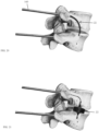
FIG. 20 illustrates a side view of a portion of the human spine showing positioning of the spinal implant with the second fitting secured within the superior endplate of the inferiorly positioned vertebral body. -
FIG. 21 illustrates a side view of a portion of the human spine showing deployment of the spinal implant with each fitting of the implant secured in their respective vertebral body endplates. -
FIG. 22 illustrates a side view of a portion of the human spine showing the spinal implant in position and filled with medical grade silicone. -
FIG. 23 illustrates a lateral view of a portion of the human spine showing the spinal implant in position. -
FIG. 24 illustrates an anteroposterior view of a portion of the human spine showing the spinal implant in position. - Before any embodiments of the invention are explained in detail, it is to be understood that the invention is not limited in its application to the details of construction and the arrangement of components set forth in the following description or illustrated in the following drawings. The invention is capable of other embodiments and of being practiced or of being carried out in various ways. Also, it is to be understood that the phraseology and terminology used herein is for the purpose of description and should not be regarded as limiting. The use of "including," "comprising," or "having" and variations thereof herein is meant to encompass the items listed thereafter and equivalents thereof as well as additional items. Unless specified or limited otherwise, the terms "connected," "supported," and "coupled" and variations thereof are used broadly and encompass both direct and indirect connections, supports, and couplings.
- Although directional references, such as upper, lower, downward, upward, rearward, bottom, front, rear, etc., may be made herein in describing the drawings, these references are made relative to the drawings (as normally viewed) for convenience. These directions are not intended to be taken literally or limit the present invention in any form. In addition, terms such as "first," "second," and "third" are used herein for purposes of description and are not intended to indicate or imply relative importance or significance.
-
FIG. 1 illustrates thehuman spine 10. Thehuman spine 10 is made up of consecutively aligned vertebral bodies 12 (i.e., vertebrae).Adjacent vertebrae 12 are separated by anintervertebral disc 14 as shown inFIG. 2 . Theintervertebral discs 14 are avascular, fibrocartilaginous structures that act as load bearing shock absorbers, yet flexible structures providing mobility to the spine. With reference toFIG. 2 , eachdisc 14 includes anucleus pulposus 16 that is enclosed within anannulus fibrosus 18. The nucleus pulposus is a soft, gel-like substance. Theannulus fibrosus 18 is made up of circumferential rings with collagen having an alternating fiber orientation. The annulus fibrosus is strongest when its height is maintained. Under normal conditions, thenucleus pulposus 16 helps maintains the vertical height of theannulus fibrosus 18 such that together, thenucleus pulposus 16 and theannulus fibrosus 18 provide tremendous axial support to thespine 10. -
FIG. 3 illustrates a disc herniation where there is a tear in theannulus fibrosus 18 that allows thenucleus pulposus 16 to bulge out beyond the damagedannulus fibrosus 18. Disc herniation is usually due to age-related disc degeneration. A tear in the annulus fibrosus and resulting disc herniation results in the release of chemicals causing inflammation and mechanically compressing the adjacent nerve roots causing severe pain. -
FIG. 4 illustrates aspinal implant 22 according to an embodiment of the present invention. Thespinal disc implant 22 provides a minimally invasive "needle based" solution to address degenerative disc disease, reduces the risk of nerve damage, maintains spine mobility (when used as a nucleus pulposus implant), and provides enhanced structural integrity to the spine. Thespinal disc implant 22 is capable of being positioned and assembled within theintervertebral disc 14. When in use, theimplant 22 replaces thenucleus pulposus 16 at a portion of the inner fibers of theannulus fibrosus 18. - The
spinal implant 22 includes abody 26 or a skeleton defined by a plurality of interwoven or braidednitinol strands 30.FIG. 5 further illustrates the braiding pattern of thenitinol strands 30. Thebody 26 includes afirst end 34 and asecond end 38. In between thefirst end 34 and thesecond end 38 is a middle cavity. Thenitinol strands 30 come together at thefirst end 34 and are secured with afirst fitting 42. Thenitinol strands 30 also come together at thesecond end 38 and are secured with asecond fitting 46. Thesecond fitting 46 can comprise a snare hook as further illustrated inFIG. 10 . In some constructions, both thefirst end 34 and thesecond end 38 can comprise a snare hook. - As illustrated in
FIG. 4 , thebody 26 defines a longitudinal axis extending through thefirst end 34 and thesecond end 38. Thebody 26 forms a slight hour-glass like shape in its unconstrained configuration for greater cross-sectional coverage and therefore a broader distribution of load forces. The middle portion includes a diameter that is slightly less than the diameter of thefirst end 34 or thesecond end 38. In some constructions, the diameter of thebody 26 gradually decreases from thefirst end 34 to the middle portion, and the diameter of thebody 26 gradually decreases from thesecond end 38 to the middle portion. Thespinal implant 22 is flexible and can change shapes when a compressive force or a tensile force is applied to theends first end 34 and thesecond end 38, theimplant 22 moves to an unconstrained state as shown inFIGS. 20-22 . Additionally, when a tensile force is applied to thefirst end 34 and thesecond end 38, theimplant 22 moves to an elongated and more narrow diameter state allowing the implant to be constrained to a small diameter for needle/cannula based delivery, as shown inFIG. 5 . - The
braided nitinol strands 30 can be coated such that the coating covers the spaces between thenitinol strands 30 to thereby form a cavity 50, which is impervious to liquids or gel-like substances from exiting and entering the cavity 50 when used as a nucleus pulposus implant. In one construction, the coating is silicone. - With reference to
FIGS. 6-13 , theimplant 22 is positioned in the intervertebral disc 14 (i.e., the space encompassed by the nucleus pulposus and inner annular fibers) with a delivery device orinstrument 100. Theinstrument 100 includes afirst coupling 104, asecond coupling 112 and apusher tube 120. Thefirst coupling 104 is bonded to thefirst fitting 42 of theimplant 22. Thefirst coupling 104 includes acircular head 128 and anextension 132. Thecircular head 128 includes anopening 136 therethrough that continues through abore 140 in theextension 132. The interior surface of theopening 136 and thebore 140 are threaded. The threaded female end (seeFIG. 8 ) receives a threaded male portion of thesecond coupling 112. Thesecond coupling 112 includes a threaded male end 116 (seeFIG. 9 ) to be threadingly received within the threaded female end of thefirst coupling 104. Thesecond coupling 112 includes abore 152 and is in fluid communication with the bore of thefirst coupling 104. Thesecond coupling 112 is bonded to apusher tube 120 configured to fit within asheath 124 for supporting and positioning theimplant 22. Theopening 136 of thefirst coupling 104 is configured to removably receive thesecond coupling 112. Thesecond coupling 112 includes abase 144 and anextension 148. A distal end of thebase 144 includes anopening 152 therethrough that continues through abore 156 in theextension 148 such that thefirst coupling 104, thesecond coupling 112, and theimplant 22 are in fluid communication through thefirst fitting 42 of theimplant 22. -
FIGS. 14-21 illustrate a method (not claimed) for positioning theimplant 22 in theintervertebral disc 14. The method can be performed as an outpatient procedure with intravenous sedation, MAC or general anesthesia. The method begins with a percutaneous and fluoroscopic-guided transpedicular (or transosseous) access into the intervertebral disc and placement of anintroducer cannula 160. Initially, access to theintervertebral disc 14 of interest is provided by drilling an access channel into the superiorly positioned vertebral body to access thedisc 14 in a transpedicular (or transosseous) manner.FIGS. 14-15 illustrate the access channel that provides transpedicular (or transosseous) access to theintervertebral disc 14. Theintervertebral disc 14 is prepared with radiofrequency augmentation to facilitate removal of the degenerated nucleus and promoting collagen repair and strengthening of the remaining annular fibers. The degenerated or damagednucleus pulposus 16 is removed percutaneously using thermal ablation and mechanical extraction devices. Additional arthroscopic tools can be used to further prepare the disc space, decompress disc herniations, and debride the cartilaginous endplates of the adjacent vertebral bodies when using the implant for inter body fusion.FIGS. 16-18 schematically illustrate removal of thenucleus pulposus 16 and preparation of the disc space for receipt of theimplant 22. - The
implant 22 is pre-mounted onto the distal end of theinstrument 100. Thefirst coupling 104 is temporarily coupled to thesecond coupling 112 as illustrated inFIG. 11 . Thepusher tube 120 is retracted to apply a tensile force to thefirst fitting 42 of theimplant 22 to thereby stretch and retract theimplant 22 into thesheath 124. Access into the disc space from both the superior and inferior vertebral bodies adjacent to the disc may facilitate disc preparation and delivery of thesecond fitting 46 into the inferiorly positioned vertebral body as illustrated inFIG. 19 . With reference toFIGS. 20-21 , thecannula 160 is flexible to enter the access channel through the intervertebral body. Theconstrained implant 22 andsheath 124 are delivered through the channel, traversing the central portion of the disc and seating thesecond fitting 46 into the inferiorly positioned vertebral body. Theimplant 22 is delivered with a combination ofsheath 124 retraction andimplant 22 pushing with thepusher tube 120 through the space where the nucleus pulposus and inner annular fibers were removed. Thesecond fitting 46 extends through the open space and comes into contact with and is embedded into the adjacent vertebral body. Thesecond fitting 46 can be configured with a snare hook end facilitating delivery of theimplant 22 into the inferiorly positioned vertebral body. The snare hook end is embedded into the vertebral body such that theimplant 22 remains in position and is less prone to migration or expulsion. - The
retractable sheath 124 from thedelivery system 100 is then completely retracted to release theimplant 22 into the open space in the intervertebral disc with thefirst fitting 42 remaining within the distal end of theretractable sheath 124. Theimplant 22 remains contained within the central disc space as illustrated inFIG. 21 upon full release of theimplant 22. Theimplant 22 remains constrained due to the space or distance between the two adjacent vertebral bodies. The space or distance is less than the length of theimplant 22 in the unconstrained state. The diameter of the implant is dimensioned to be similar to the diameter of the open space where the nucleus pulposus and inner annular fibers were removed. While theinstrument 100 is still coupled to theimplant 22, the cavity of the implant may be injected with a substance through thehollow pusher tube 120, through thesecond coupling 112 to theimplant 22, and filling theimplant 22 to its complete state with full expansion in the Z axis. Theimplant 22 is filled with liquid, gel, silicone, or bone graft materials. After complete deployment and filling of theimplant 22, thesecond coupling 112 of thedelivery instrument 100 is rotatably detached from thefirst fitting 42 on the first end of theimplant 22 and is retracted from theaccess cannula 160. Bone graft material or methymethacrylate can then be injected through theaccess cannula 160 to fix the first and second fittings in their respective vertebral bodies.FIGS. 22-24 illustrate theimplant 22 in position. Theimplant 22 replaces a degenerated nucleus pulposus and restores the annular height for improved structural integrity. Theimplant 22 can also be used as an internally assembled inter-body fusion implant when using a non-coated nitinol skeleton (not claimed) and filling the implant with bone graft material. - It is noted that this
implant 22 is in contrast to other implants that have no endoskeleton beyond that of the outer wall (such as in a balloon). Theimplant 22 is not a simple balloon, but rather an internally assembled device constrained in the XY plane and secured within the adjacent endplates of the adjacent vertebral bodies. The diameter and height of theimplant 22 is customized to the patient's anatomy based on pre-operative MR imaging. The XY constraint is important, as a simple balloon may not have as accurate a shape as desired. The filling of theimplant 22 will then complete the shape of theimplant 22 and specifically provide shape and support in the Z axis (cranial and caudal). SeeFIG. 22 for reference coordinates. - To demonstrate the capability of the
implant 22, it was axially load tested to determine the compressive load it could withstand. Theimplant 22 was capable of handling 450 lbf (2.0 kN). These measurements indicate that theimplant 22 performs above ASTM standards. - Various features and advantages of the invention are set forth in the following claims.
Claims (12)
- A spinal disc implant (22) suitable for a trans-osseous method, the implant comprisinga body (26) comprising a plurality of braided nitinol strands defining a first end, a second end, and an interior cavity;a coating applied to the body to provide an impervious barrier to liquids or gel-like substances from entering the interior cavity;a first fitting (42) coupled to the first end and configured to be embedded in an inferior aspect of a first vertebral body; anda second fitting (46) coupled to the second end and configured to be embedded in a superior aspect of a second vertebral body adjacent to the first vertebral body.
- The spinal disc implant of claim 1, wherein the body forms a slight hour-glass like shape.
- The spinal disc implant of claim 1, wherein the second fitting comprises a snare hook.
- The spinal disc implant of claim 1, wherein the first fitting is configured to removably couple to a delivery instrument allowing repositioning and detachment of the implant.
- The spinal disc implant of claim 1, wherein the coating is silicone.
- The spinal disc implant of claim 1, wherein a middle portion of the implant includes a first diameter, and wherein the first end includes a second diameter, and further wherein the first diameter is less than the second diameter.
- The spinal disc implant of claim 1, wherein the first end includes a first diameter, and wherein the second end includes a second diameter, and further wherein the first diameter is the same as the second diameter.
- The spinal disc implant of claim 1, wherein the plurality of braided nitinol strands is flexible such that the implant stretches and lengthens when a tensile force is applied to the first fitting and the second fitting.
- The spinal disc implant of claim 1, wherein the plurality of braided nitinol strands is flexible such that the implant is self-expanded when a compression force is applied to the first fitting and the second fitting.
- A device (100) for positioning the spinal disc implant according to any one of claims 1 to 9, the device comprising:a first coupling (104) bonded to the spinal disc implant, the first coupling including a threaded bore; anda second coupling (112) bonded to a pusher tube (120) and removably coupled to the first coupling, the second coupling including a male threaded end (116) configured to be received by the threaded bore (140) of the first coupling;wherein the pusher tube is configured to move the spinal disc implant out of a cannula and into position between a first vertebral body and a second vertebral body adjacent to the first vertebral body.
- The device of claim 10, wherein the second coupling includes a bore (152) therethrough such that the bore is in fluid communication with the threaded bore of the first coupling.
- The device of claim 10, wherein the pusher tube is a hollow pusher tube configured to deliver liquids, gels, silicone or bone graft material from a delivery handle through the first and second couplings and into an interior chamber of the spinal disc implant.
Applications Claiming Priority (1)
| Application Number | Priority Date | Filing Date | Title |
|---|---|---|---|
| PCT/US2018/013578 WO2019139618A1 (en) | 2018-01-12 | 2018-01-12 | Spinal disc implant and device and method for percutaneous delivery of the spinal disc implant |
Publications (4)
| Publication Number | Publication Date |
|---|---|
| EP3737338A1 EP3737338A1 (en) | 2020-11-18 |
| EP3737338A4 EP3737338A4 (en) | 2021-09-22 |
| EP3737338B1 true EP3737338B1 (en) | 2024-04-10 |
| EP3737338C0 EP3737338C0 (en) | 2024-04-10 |
Family
ID=67219111
Family Applications (1)
| Application Number | Title | Priority Date | Filing Date |
|---|---|---|---|
| EP18899340.6A Active EP3737338B1 (en) | 2018-01-12 | 2018-01-12 | Spinal disc implant and device and method for percutaneous delivery of the spinal disc implant |
Country Status (3)
| Country | Link |
|---|---|
| US (4) | US11419733B2 (en) |
| EP (1) | EP3737338B1 (en) |
| WO (1) | WO2019139618A1 (en) |
Citations (1)
| Publication number | Priority date | Publication date | Assignee | Title |
|---|---|---|---|---|
| US20020077701A1 (en) * | 2000-12-15 | 2002-06-20 | Kuslich Stephen D. | Annulus-reinforcing band |
Family Cites Families (79)
| Publication number | Priority date | Publication date | Assignee | Title |
|---|---|---|---|---|
| US3875595A (en) | 1974-04-15 | 1975-04-08 | Edward C Froning | Intervertebral disc prosthesis and instruments for locating same |
| US4772287A (en) | 1987-08-20 | 1988-09-20 | Cedar Surgical, Inc. | Prosthetic disc and method of implanting |
| US4969888A (en) | 1989-02-09 | 1990-11-13 | Arie Scholten | Surgical protocol for fixation of osteoporotic bone using inflatable device |
| US5571189A (en) | 1994-05-20 | 1996-11-05 | Kuslich; Stephen D. | Expandable fabric implant for stabilizing the spinal motion segment |
| US5562736A (en) | 1994-10-17 | 1996-10-08 | Raymedica, Inc. | Method for surgical implantation of a prosthetic spinal disc nucleus |
| US5645597A (en) | 1995-12-29 | 1997-07-08 | Krapiva; Pavel I. | Disc replacement method and apparatus |
| EP0873145A2 (en) | 1996-11-15 | 1998-10-28 | Advanced Bio Surfaces, Inc. | Biomaterial system for in situ tissue repair |
| IL128261A0 (en) | 1999-01-27 | 1999-11-30 | Disc O Tech Medical Tech Ltd | Expandable element |
| US6852095B1 (en) | 1997-07-09 | 2005-02-08 | Charles D. Ray | Interbody device and method for treatment of osteoporotic vertebral collapse |
| AU3203599A (en) | 1998-04-01 | 1999-10-18 | Parallax Medical, Inc. | Pressure applicator for hard tissue implant placement |
| AU4810800A (en) | 1999-04-26 | 2000-11-10 | Li Medical Technologies, Inc. | Prosthetic apparatus and method |
| US6733505B2 (en) | 2000-04-26 | 2004-05-11 | Sdgi Holdings, Inc. | Apparatus and method for loading a prosthetic nucleus into a deployment cannula to replace the nucleus pulposus of an intervertebral disc |
| US20070038231A1 (en) | 1999-05-28 | 2007-02-15 | Ferree Bret A | Methods and apparatus for treating disc herniation and preventing the extrusion of interbody bone graft |
| IL155494A0 (en) | 1999-08-18 | 2003-11-23 | Intrinsic Therapeutics Inc | Devices and method for nucleus pulposus augmentation and retention |
| WO2001032100A2 (en) | 1999-10-29 | 2001-05-10 | Drexel University | Associating hydrogels for nucleus pulposus replacement in intervertebral discs |
| US7214245B1 (en) | 1999-10-29 | 2007-05-08 | Drexel University | Associating hydrogels for nucleus pulposus replacement in intervertebral discs |
| US7662173B2 (en) | 2000-02-16 | 2010-02-16 | Transl, Inc. | Spinal mobility preservation apparatus |
| US6740093B2 (en) | 2000-02-28 | 2004-05-25 | Stephen Hochschuler | Method and apparatus for treating a vertebral body |
| US20030040800A1 (en) | 2000-04-26 | 2003-02-27 | Li Lehmann K. | Apparatus and method for replacing the nucleus pulposus of an intervertebral disc or for replacing an entire intervertebral disc |
| US20020026244A1 (en) | 2000-08-30 | 2002-02-28 | Trieu Hai H. | Intervertebral disc nucleus implants and methods |
| US6582467B1 (en) | 2000-10-31 | 2003-06-24 | Vertelink Corporation | Expandable fusion cage |
| US20020147479A1 (en) | 2001-04-06 | 2002-10-10 | Integrated Vascular Systems, Inc. | Apparatus and methods for sealing openings through tissue |
| WO2003002021A2 (en) | 2001-06-29 | 2003-01-09 | The Regents Of The University Of California | Biodegradable/bioactive nucleus pulposus implant and method for treating degenerated intervertebral discs |
| US7267687B2 (en) | 2001-10-02 | 2007-09-11 | Rex Medical, L.P | Spinal implant and method of use |
| DE10154163A1 (en) | 2001-11-03 | 2003-05-22 | Advanced Med Tech | Device for straightening and stabilizing the spine |
| GB2382028B (en) | 2001-11-19 | 2006-11-01 | Aberdeen Orthopaedic Developme | Intervertebral disc prosthesis |
| JP2005516648A (en) | 2001-12-13 | 2005-06-09 | エスディージーアイ・ホールディングス・インコーポレーテッド | Instruments and methods for introducing an implant into a vertebral space |
| US7128746B2 (en) | 2002-05-16 | 2006-10-31 | Pmt Corporation | Device for treating intervertebral disc herniations |
| US20040030345A1 (en) | 2002-08-09 | 2004-02-12 | Aurin Gary Douglas | Bone cement syringe |
| US7488337B2 (en) | 2002-09-30 | 2009-02-10 | Saab Mark A | Apparatus and methods for bone, tissue and duct dilatation |
| US6733533B1 (en) | 2002-11-19 | 2004-05-11 | Zimmer Technology, Inc. | Artificial spinal disc |
| US20040186471A1 (en) | 2002-12-07 | 2004-09-23 | Sdgi Holdings, Inc. | Method and apparatus for intervertebral disc expansion |
| WO2004064673A2 (en) | 2003-01-17 | 2004-08-05 | Psinergi Corporation | Artificial nucleus pulposus and method of injecting same |
| US7632291B2 (en) | 2003-06-13 | 2009-12-15 | Trivascular2, Inc. | Inflatable implant |
| US20050043796A1 (en) | 2003-07-01 | 2005-02-24 | Grant Richard L. | Spinal disc nucleus implant |
| US20050015150A1 (en) * | 2003-07-17 | 2005-01-20 | Lee Casey K. | Intervertebral disk and nucleus prosthesis |
| KR20060132588A (en) * | 2003-10-23 | 2006-12-21 | 트랜스1 인코포레이티드 | Tools and tool kits for performing minimal intervention of the spine |
| US20050143826A1 (en) | 2003-12-11 | 2005-06-30 | St. Francis Medical Technologies, Inc. | Disk repair structures with anchors |
| US7465318B2 (en) | 2004-04-15 | 2008-12-16 | Soteira, Inc. | Cement-directing orthopedic implants |
| US20050245938A1 (en) | 2004-04-28 | 2005-11-03 | Kochan Jeffrey P | Method and apparatus for minimally invasive repair of intervertebral discs and articular joints |
| EP1786343B1 (en) | 2004-07-30 | 2012-05-02 | Depuy Spine, Inc. | Apparatus for treating bone and other tissue |
| US8038682B2 (en) | 2004-08-17 | 2011-10-18 | Boston Scientific Scimed, Inc. | Apparatus and methods for delivering compounds into vertebrae for vertebroplasty |
| JP2006068086A (en) * | 2004-08-31 | 2006-03-16 | Takiron Co Ltd | Artificial spinal disk insertion tool and tool set |
| US7682335B2 (en) | 2004-10-15 | 2010-03-23 | Futurematrix Interventional, Inc. | Non-compliant medical balloon having an integral non-woven fabric layer |
| US7799078B2 (en) | 2004-11-12 | 2010-09-21 | Warsaw Orthopedic, Inc. | Implantable vertebral lift |
| WO2006060482A2 (en) | 2004-12-01 | 2006-06-08 | The Regents Of The University Of California | Systems, devices and methods of treatment of intervertebral disorders |
| US20060247657A1 (en) | 2005-04-27 | 2006-11-02 | Sdgi Holdings, Inc. | Methods and systems for characterizing intervertebral disc space |
| WO2006116761A2 (en) * | 2005-04-27 | 2006-11-02 | Stout Medical Group, L.P. | Expandable support device and methods of use |
| US8092464B2 (en) | 2005-04-30 | 2012-01-10 | Warsaw Orthopedic, Inc. | Syringe devices and methods useful for delivering osteogenic material |
| US7628800B2 (en) | 2005-06-03 | 2009-12-08 | Warsaw Orthopedic, Inc. | Formed in place corpectomy device |
| US20110270399A1 (en) | 2005-06-15 | 2011-11-03 | Matthew Yurek | Mechanical Apparatus and Method for Artificial Disc Fusion and Nucleus Replacement |
| EP1909658A2 (en) | 2005-07-11 | 2008-04-16 | Kyphon Inc. | Systems and methods for providing cavities in interior body regions |
| EP1903949A2 (en) | 2005-07-14 | 2008-04-02 | Stout Medical Group, L.P. | Expandable support device and method of use |
| AU2006282883A1 (en) | 2005-08-26 | 2007-03-01 | Synthes Gmbh | Hydrogel balloon prosthesis for nucleus pulposus |
| US20070088436A1 (en) | 2005-09-29 | 2007-04-19 | Matthew Parsons | Methods and devices for stenting or tamping a fractured vertebral body |
| US20070135921A1 (en) * | 2005-12-09 | 2007-06-14 | Park Kee B | Surgical implant |
| US7699894B2 (en) | 2005-12-22 | 2010-04-20 | Depuy Spine, Inc. | Nucleus pulposus trial device and technique |
| US20070276497A1 (en) * | 2006-05-23 | 2007-11-29 | Sdgi Holdings. Inc. | Surgical spacer |
| US20090131939A1 (en) | 2006-05-24 | 2009-05-21 | Disc Dynamics, Inc. | Inflatable mold for maintaining posterior spinal elements in a desired alignment |
| US8088147B2 (en) * | 2006-10-24 | 2012-01-03 | Trans1 Inc. | Multi-membrane prosthetic nucleus |
| US8979931B2 (en) | 2006-12-08 | 2015-03-17 | DePuy Synthes Products, LLC | Nucleus replacement device and method |
| US8298286B2 (en) * | 2006-12-19 | 2012-10-30 | Warsaw Orthopedic, Inc. | Non-linear vertebral mesh |
| US8403937B2 (en) | 2007-03-30 | 2013-03-26 | Kyphon Sarl | Apparatus and method for medical procedures within a spine |
| US9687353B2 (en) | 2007-03-31 | 2017-06-27 | Spinal Kinetics, Inc. | Prosthetic intervertebral discs having balloon-based fillable cores that are implantable by minimally invasive surgical techniques |
| US8043381B2 (en) * | 2007-10-29 | 2011-10-25 | Zimmer Spine, Inc. | Minimally invasive interbody device and method |
| US20090149958A1 (en) | 2007-11-01 | 2009-06-11 | Ann Prewett | Structurally reinforced spinal nucleus implants |
| US8292961B2 (en) | 2008-01-23 | 2012-10-23 | Osman Said G | Biologic vertebral reconstruction |
| FR2929502B1 (en) | 2008-04-04 | 2011-04-08 | Clariance | NUCLEIC IMPLANT. |
| US7976578B2 (en) | 2008-06-04 | 2011-07-12 | James Marvel | Buffer for a human joint and method of arthroscopically inserting |
| EP2339985A4 (en) | 2008-09-12 | 2013-07-03 | Articulinx Inc | Tether-based orthopedic joint device delivery methods |
| US20100145454A1 (en) | 2008-12-09 | 2010-06-10 | Zimmer Spine, Inc. | Intervertebral disc nucleus replacement prosthesis |
| KR20120047231A (en) | 2009-06-17 | 2012-05-11 | 트리니티 올쏘피딕스, 엘엘씨 | Expanding intervertebral device and methods of use |
| EP2467099B1 (en) | 2009-08-19 | 2019-05-15 | Synthes GmbH | Apparatus for augmenting bone |
| US9078761B2 (en) * | 2009-11-12 | 2015-07-14 | Anchor Orthopedics Xt Inc. | Devices and methods for treating tissue defects |
| US8864711B2 (en) | 2010-01-27 | 2014-10-21 | Warsaw Orthopedic, Inc. | Drug dispensing balloon for treating disc disease or pain |
| WO2012064473A1 (en) * | 2010-11-09 | 2012-05-18 | Med Institute, Inc. | Covered stent devices for use in treatment of fracture |
| US10285818B2 (en) | 2012-12-26 | 2019-05-14 | Symbiomedik, Llc | Apparatus, kit, and method for percutaneous intervertebral disc restoration |
| US9572676B2 (en) * | 2013-03-14 | 2017-02-21 | DePuy Synthes Products, Inc. | Adjustable multi-volume balloon for spinal interventions |
| US9955976B2 (en) * | 2013-08-16 | 2018-05-01 | Sequent Medical, Inc. | Filamentary devices for treatment of vascular defects |
-
2018
- 2018-01-12 EP EP18899340.6A patent/EP3737338B1/en active Active
- 2018-01-12 US US16/961,758 patent/US11419733B2/en active Active
- 2018-01-12 WO PCT/US2018/013578 patent/WO2019139618A1/en not_active Ceased
-
2022
- 2022-08-23 US US17/821,729 patent/US11957597B2/en active Active
-
2024
- 2024-03-20 US US18/611,097 patent/US12318303B2/en active Active
-
2025
- 2025-05-09 US US19/203,989 patent/US20250262060A1/en active Pending
Patent Citations (1)
| Publication number | Priority date | Publication date | Assignee | Title |
|---|---|---|---|---|
| US20020077701A1 (en) * | 2000-12-15 | 2002-06-20 | Kuslich Stephen D. | Annulus-reinforcing band |
Also Published As
| Publication number | Publication date |
|---|---|
| EP3737338A1 (en) | 2020-11-18 |
| US11957597B2 (en) | 2024-04-16 |
| EP3737338A4 (en) | 2021-09-22 |
| US12318303B2 (en) | 2025-06-03 |
| US20210059831A1 (en) | 2021-03-04 |
| US20240225850A1 (en) | 2024-07-11 |
| US11419733B2 (en) | 2022-08-23 |
| WO2019139618A1 (en) | 2019-07-18 |
| US20220395380A1 (en) | 2022-12-15 |
| EP3737338C0 (en) | 2024-04-10 |
| US20250262060A1 (en) | 2025-08-21 |
Similar Documents
| Publication | Publication Date | Title |
|---|---|---|
| US10327912B1 (en) | Expandable interbody spinal fusion device capable of being deployed endoscopically | |
| US6899716B2 (en) | Method and apparatus for spinal augmentation | |
| US7744599B2 (en) | Articulating spinal implant | |
| US10314718B2 (en) | Expandable intervertebral fusion implant | |
| US7608077B2 (en) | Method and apparatus for spinal distraction and fusion | |
| US10285818B2 (en) | Apparatus, kit, and method for percutaneous intervertebral disc restoration | |
| US20170360570A1 (en) | Apparatus and methods for spine and sacroiliac joint repair | |
| JP2004516904A (en) | Apparatus and method for nucleus pulposus augmentation and retention | |
| KR20110136846A (en) | Spine Bone Restoration Device and How to Use | |
| WO2006047640A2 (en) | Simultaneous axial delivery of spinal implants | |
| US12318303B2 (en) | Spinal disc implant and device and method for percutaneous delivery of the spinal disc implant | |
| US20250032269A1 (en) | Implant | |
| JP2008517675A (en) | Simultaneous axial delivery of spinal implants |
Legal Events
| Date | Code | Title | Description |
|---|---|---|---|
| STAA | Information on the status of an ep patent application or granted ep patent |
Free format text: STATUS: THE INTERNATIONAL PUBLICATION HAS BEEN MADE |
|
| PUAI | Public reference made under article 153(3) epc to a published international application that has entered the european phase |
Free format text: ORIGINAL CODE: 0009012 |
|
| STAA | Information on the status of an ep patent application or granted ep patent |
Free format text: STATUS: REQUEST FOR EXAMINATION WAS MADE |
|
| 17P | Request for examination filed |
Effective date: 20200812 |
|
| AK | Designated contracting states |
Kind code of ref document: A1 Designated state(s): AL AT BE BG CH CY CZ DE DK EE ES FI FR GB GR HR HU IE IS IT LI LT LU LV MC MK MT NL NO PL PT RO RS SE SI SK SM TR |
|
| AX | Request for extension of the european patent |
Extension state: BA ME |
|
| DAV | Request for validation of the european patent (deleted) | ||
| DAX | Request for extension of the european patent (deleted) | ||
| A4 | Supplementary search report drawn up and despatched |
Effective date: 20210824 |
|
| RIC1 | Information provided on ipc code assigned before grant |
Ipc: A61F 2/46 20060101ALI20210818BHEP Ipc: A61F 2/44 20060101AFI20210818BHEP |
|
| GRAP | Despatch of communication of intention to grant a patent |
Free format text: ORIGINAL CODE: EPIDOSNIGR1 |
|
| STAA | Information on the status of an ep patent application or granted ep patent |
Free format text: STATUS: GRANT OF PATENT IS INTENDED |
|
| INTG | Intention to grant announced |
Effective date: 20231102 |
|
| RAP1 | Party data changed (applicant data changed or rights of an application transferred) |
Owner name: PERCHERON SPINE, LLC |
|
| GRAS | Grant fee paid |
Free format text: ORIGINAL CODE: EPIDOSNIGR3 |
|
| GRAA | (expected) grant |
Free format text: ORIGINAL CODE: 0009210 |
|
| STAA | Information on the status of an ep patent application or granted ep patent |
Free format text: STATUS: THE PATENT HAS BEEN GRANTED |
|
| AK | Designated contracting states |
Kind code of ref document: B1 Designated state(s): AL AT BE BG CH CY CZ DE DK EE ES FI FR GB GR HR HU IE IS IT LI LT LU LV MC MK MT NL NO PL PT RO RS SE SI SK SM TR |
|
| REG | Reference to a national code |
Ref country code: GB Ref legal event code: FG4D |
|
| REG | Reference to a national code |
Ref country code: CH Ref legal event code: EP |
|
| REG | Reference to a national code |
Ref country code: DE Ref legal event code: R096 Ref document number: 602018068041 Country of ref document: DE |
|
| REG | Reference to a national code |
Ref country code: IE Ref legal event code: FG4D |
|
| U01 | Request for unitary effect filed |
Effective date: 20240422 |
|
| U07 | Unitary effect registered |
Designated state(s): AT BE BG DE DK EE FI FR IT LT LU LV MT NL PT SE SI Effective date: 20240430 |
|
| PG25 | Lapsed in a contracting state [announced via postgrant information from national office to epo] |
Ref country code: IS Free format text: LAPSE BECAUSE OF FAILURE TO SUBMIT A TRANSLATION OF THE DESCRIPTION OR TO PAY THE FEE WITHIN THE PRESCRIBED TIME-LIMIT Effective date: 20240810 |
|
| PG25 | Lapsed in a contracting state [announced via postgrant information from national office to epo] |
Ref country code: HR Free format text: LAPSE BECAUSE OF FAILURE TO SUBMIT A TRANSLATION OF THE DESCRIPTION OR TO PAY THE FEE WITHIN THE PRESCRIBED TIME-LIMIT Effective date: 20240410 |
|
| PG25 | Lapsed in a contracting state [announced via postgrant information from national office to epo] |
Ref country code: GR Free format text: LAPSE BECAUSE OF FAILURE TO SUBMIT A TRANSLATION OF THE DESCRIPTION OR TO PAY THE FEE WITHIN THE PRESCRIBED TIME-LIMIT Effective date: 20240711 |
|
| PG25 | Lapsed in a contracting state [announced via postgrant information from national office to epo] |
Ref country code: ES Free format text: LAPSE BECAUSE OF FAILURE TO SUBMIT A TRANSLATION OF THE DESCRIPTION OR TO PAY THE FEE WITHIN THE PRESCRIBED TIME-LIMIT Effective date: 20240410 |
|
| PG25 | Lapsed in a contracting state [announced via postgrant information from national office to epo] |
Ref country code: PL Free format text: LAPSE BECAUSE OF FAILURE TO SUBMIT A TRANSLATION OF THE DESCRIPTION OR TO PAY THE FEE WITHIN THE PRESCRIBED TIME-LIMIT Effective date: 20240410 |
|
| PG25 | Lapsed in a contracting state [announced via postgrant information from national office to epo] |
Ref country code: PL Free format text: LAPSE BECAUSE OF FAILURE TO SUBMIT A TRANSLATION OF THE DESCRIPTION OR TO PAY THE FEE WITHIN THE PRESCRIBED TIME-LIMIT Effective date: 20240410 Ref country code: NO Free format text: LAPSE BECAUSE OF FAILURE TO SUBMIT A TRANSLATION OF THE DESCRIPTION OR TO PAY THE FEE WITHIN THE PRESCRIBED TIME-LIMIT Effective date: 20240710 Ref country code: IS Free format text: LAPSE BECAUSE OF FAILURE TO SUBMIT A TRANSLATION OF THE DESCRIPTION OR TO PAY THE FEE WITHIN THE PRESCRIBED TIME-LIMIT Effective date: 20240810 Ref country code: HR Free format text: LAPSE BECAUSE OF FAILURE TO SUBMIT A TRANSLATION OF THE DESCRIPTION OR TO PAY THE FEE WITHIN THE PRESCRIBED TIME-LIMIT Effective date: 20240410 Ref country code: GR Free format text: LAPSE BECAUSE OF FAILURE TO SUBMIT A TRANSLATION OF THE DESCRIPTION OR TO PAY THE FEE WITHIN THE PRESCRIBED TIME-LIMIT Effective date: 20240711 Ref country code: ES Free format text: LAPSE BECAUSE OF FAILURE TO SUBMIT A TRANSLATION OF THE DESCRIPTION OR TO PAY THE FEE WITHIN THE PRESCRIBED TIME-LIMIT Effective date: 20240410 Ref country code: RS Free format text: LAPSE BECAUSE OF FAILURE TO SUBMIT A TRANSLATION OF THE DESCRIPTION OR TO PAY THE FEE WITHIN THE PRESCRIBED TIME-LIMIT Effective date: 20240710 |
|
| REG | Reference to a national code |
Ref country code: DE Ref legal event code: R097 Ref document number: 602018068041 Country of ref document: DE |
|
| PG25 | Lapsed in a contracting state [announced via postgrant information from national office to epo] |
Ref country code: CZ Free format text: LAPSE BECAUSE OF FAILURE TO SUBMIT A TRANSLATION OF THE DESCRIPTION OR TO PAY THE FEE WITHIN THE PRESCRIBED TIME-LIMIT Effective date: 20240410 |
|
| PG25 | Lapsed in a contracting state [announced via postgrant information from national office to epo] |
Ref country code: SK Free format text: LAPSE BECAUSE OF FAILURE TO SUBMIT A TRANSLATION OF THE DESCRIPTION OR TO PAY THE FEE WITHIN THE PRESCRIBED TIME-LIMIT Effective date: 20240410 Ref country code: RO Free format text: LAPSE BECAUSE OF FAILURE TO SUBMIT A TRANSLATION OF THE DESCRIPTION OR TO PAY THE FEE WITHIN THE PRESCRIBED TIME-LIMIT Effective date: 20240410 |
|
| PG25 | Lapsed in a contracting state [announced via postgrant information from national office to epo] |
Ref country code: SM Free format text: LAPSE BECAUSE OF FAILURE TO SUBMIT A TRANSLATION OF THE DESCRIPTION OR TO PAY THE FEE WITHIN THE PRESCRIBED TIME-LIMIT Effective date: 20240410 |
|
| PG25 | Lapsed in a contracting state [announced via postgrant information from national office to epo] |
Ref country code: SM Free format text: LAPSE BECAUSE OF FAILURE TO SUBMIT A TRANSLATION OF THE DESCRIPTION OR TO PAY THE FEE WITHIN THE PRESCRIBED TIME-LIMIT Effective date: 20240410 Ref country code: SK Free format text: LAPSE BECAUSE OF FAILURE TO SUBMIT A TRANSLATION OF THE DESCRIPTION OR TO PAY THE FEE WITHIN THE PRESCRIBED TIME-LIMIT Effective date: 20240410 Ref country code: RO Free format text: LAPSE BECAUSE OF FAILURE TO SUBMIT A TRANSLATION OF THE DESCRIPTION OR TO PAY THE FEE WITHIN THE PRESCRIBED TIME-LIMIT Effective date: 20240410 Ref country code: CZ Free format text: LAPSE BECAUSE OF FAILURE TO SUBMIT A TRANSLATION OF THE DESCRIPTION OR TO PAY THE FEE WITHIN THE PRESCRIBED TIME-LIMIT Effective date: 20240410 |
|
| PLBE | No opposition filed within time limit |
Free format text: ORIGINAL CODE: 0009261 |
|
| STAA | Information on the status of an ep patent application or granted ep patent |
Free format text: STATUS: NO OPPOSITION FILED WITHIN TIME LIMIT |
|
| U20 | Renewal fee for the european patent with unitary effect paid |
Year of fee payment: 8 Effective date: 20250122 |
|
| 26N | No opposition filed |
Effective date: 20250113 |
|
| PGFP | Annual fee paid to national office [announced via postgrant information from national office to epo] |
Ref country code: GB Payment date: 20250109 Year of fee payment: 8 |
|
| REG | Reference to a national code |
Ref country code: CH Ref legal event code: PL |
|
| PG25 | Lapsed in a contracting state [announced via postgrant information from national office to epo] |
Ref country code: MC Free format text: LAPSE BECAUSE OF FAILURE TO SUBMIT A TRANSLATION OF THE DESCRIPTION OR TO PAY THE FEE WITHIN THE PRESCRIBED TIME-LIMIT Effective date: 20240410 |
|
| PG25 | Lapsed in a contracting state [announced via postgrant information from national office to epo] |
Ref country code: CH Free format text: LAPSE BECAUSE OF NON-PAYMENT OF DUE FEES Effective date: 20250131 |
|
| PG25 | Lapsed in a contracting state [announced via postgrant information from national office to epo] |
Ref country code: IE Free format text: LAPSE BECAUSE OF NON-PAYMENT OF DUE FEES Effective date: 20250112 |