EP3723828B1 - Devices and methods for precision dose delivery - Google Patents
Devices and methods for precision dose delivery Download PDFInfo
- Publication number
- EP3723828B1 EP3723828B1 EP18836978.9A EP18836978A EP3723828B1 EP 3723828 B1 EP3723828 B1 EP 3723828B1 EP 18836978 A EP18836978 A EP 18836978A EP 3723828 B1 EP3723828 B1 EP 3723828B1
- Authority
- EP
- European Patent Office
- Prior art keywords
- plunger rod
- plunger
- sleeve
- delivery device
- syringe
- Prior art date
- Legal status (The legal status is an assumption and is not a legal conclusion. Google has not performed a legal analysis and makes no representation as to the accuracy of the status listed.)
- Active
Links
Images


Classifications
-
- A—HUMAN NECESSITIES
- A61—MEDICAL OR VETERINARY SCIENCE; HYGIENE
- A61M—DEVICES FOR INTRODUCING MEDIA INTO, OR ONTO, THE BODY; DEVICES FOR TRANSDUCING BODY MEDIA OR FOR TAKING MEDIA FROM THE BODY; DEVICES FOR PRODUCING OR ENDING SLEEP OR STUPOR
- A61M5/00—Devices for bringing media into the body in a subcutaneous, intra-vascular or intramuscular way; Accessories therefor, e.g. filling or cleaning devices, arm-rests
- A61M5/178—Syringes
- A61M5/31—Details
- A61M5/315—Pistons; Piston-rods; Guiding, blocking or restricting the movement of the rod or piston; Appliances on the rod for facilitating dosing ; Dosing mechanisms
- A61M5/31565—Administration mechanisms, i.e. constructional features, modes of administering a dose
- A61M5/31566—Means improving security or handling thereof
- A61M5/31573—Accuracy improving means
- A61M5/31575—Accuracy improving means using scaling up or down transmissions, e.g. gearbox
-
- A—HUMAN NECESSITIES
- A61—MEDICAL OR VETERINARY SCIENCE; HYGIENE
- A61M—DEVICES FOR INTRODUCING MEDIA INTO, OR ONTO, THE BODY; DEVICES FOR TRANSDUCING BODY MEDIA OR FOR TAKING MEDIA FROM THE BODY; DEVICES FOR PRODUCING OR ENDING SLEEP OR STUPOR
- A61M5/00—Devices for bringing media into the body in a subcutaneous, intra-vascular or intramuscular way; Accessories therefor, e.g. filling or cleaning devices, arm-rests
- A61M5/178—Syringes
- A61M5/31—Details
- A61M5/315—Pistons; Piston-rods; Guiding, blocking or restricting the movement of the rod or piston; Appliances on the rod for facilitating dosing ; Dosing mechanisms
- A61M5/31501—Means for blocking or restricting the movement of the rod or piston
-
- A—HUMAN NECESSITIES
- A61—MEDICAL OR VETERINARY SCIENCE; HYGIENE
- A61M—DEVICES FOR INTRODUCING MEDIA INTO, OR ONTO, THE BODY; DEVICES FOR TRANSDUCING BODY MEDIA OR FOR TAKING MEDIA FROM THE BODY; DEVICES FOR PRODUCING OR ENDING SLEEP OR STUPOR
- A61M5/00—Devices for bringing media into the body in a subcutaneous, intra-vascular or intramuscular way; Accessories therefor, e.g. filling or cleaning devices, arm-rests
- A61M5/178—Syringes
- A61M5/31—Details
- A61M5/315—Pistons; Piston-rods; Guiding, blocking or restricting the movement of the rod or piston; Appliances on the rod for facilitating dosing ; Dosing mechanisms
- A61M5/31511—Piston or piston-rod constructions, e.g. connection of piston with piston-rod
-
- A—HUMAN NECESSITIES
- A61—MEDICAL OR VETERINARY SCIENCE; HYGIENE
- A61M—DEVICES FOR INTRODUCING MEDIA INTO, OR ONTO, THE BODY; DEVICES FOR TRANSDUCING BODY MEDIA OR FOR TAKING MEDIA FROM THE BODY; DEVICES FOR PRODUCING OR ENDING SLEEP OR STUPOR
- A61M5/00—Devices for bringing media into the body in a subcutaneous, intra-vascular or intramuscular way; Accessories therefor, e.g. filling or cleaning devices, arm-rests
- A61M5/178—Syringes
- A61M5/31—Details
- A61M5/315—Pistons; Piston-rods; Guiding, blocking or restricting the movement of the rod or piston; Appliances on the rod for facilitating dosing ; Dosing mechanisms
- A61M5/31525—Dosing
- A61M5/31526—Dosing by means of stepwise axial movements, e.g. ratchet mechanisms or detents
-
- A—HUMAN NECESSITIES
- A61—MEDICAL OR VETERINARY SCIENCE; HYGIENE
- A61M—DEVICES FOR INTRODUCING MEDIA INTO, OR ONTO, THE BODY; DEVICES FOR TRANSDUCING BODY MEDIA OR FOR TAKING MEDIA FROM THE BODY; DEVICES FOR PRODUCING OR ENDING SLEEP OR STUPOR
- A61M5/00—Devices for bringing media into the body in a subcutaneous, intra-vascular or intramuscular way; Accessories therefor, e.g. filling or cleaning devices, arm-rests
- A61M5/178—Syringes
- A61M5/31—Details
- A61M5/315—Pistons; Piston-rods; Guiding, blocking or restricting the movement of the rod or piston; Appliances on the rod for facilitating dosing ; Dosing mechanisms
- A61M5/31533—Dosing mechanisms, i.e. setting a dose
- A61M5/31535—Means improving security or handling thereof, e.g. blocking means, means preventing insufficient dosing, means allowing correction of overset dose
- A61M5/31536—Blocking means to immobilize a selected dose, e.g. to administer equal doses
-
- A—HUMAN NECESSITIES
- A61—MEDICAL OR VETERINARY SCIENCE; HYGIENE
- A61M—DEVICES FOR INTRODUCING MEDIA INTO, OR ONTO, THE BODY; DEVICES FOR TRANSDUCING BODY MEDIA OR FOR TAKING MEDIA FROM THE BODY; DEVICES FOR PRODUCING OR ENDING SLEEP OR STUPOR
- A61M5/00—Devices for bringing media into the body in a subcutaneous, intra-vascular or intramuscular way; Accessories therefor, e.g. filling or cleaning devices, arm-rests
- A61M5/178—Syringes
- A61M5/31—Details
- A61M5/315—Pistons; Piston-rods; Guiding, blocking or restricting the movement of the rod or piston; Appliances on the rod for facilitating dosing ; Dosing mechanisms
- A61M5/31533—Dosing mechanisms, i.e. setting a dose
- A61M5/31545—Setting modes for dosing
- A61M5/31548—Mechanically operated dose setting member
- A61M5/3155—Mechanically operated dose setting member by rotational movement of dose setting member, e.g. during setting or filling of a syringe
-
- A—HUMAN NECESSITIES
- A61—MEDICAL OR VETERINARY SCIENCE; HYGIENE
- A61M—DEVICES FOR INTRODUCING MEDIA INTO, OR ONTO, THE BODY; DEVICES FOR TRANSDUCING BODY MEDIA OR FOR TAKING MEDIA FROM THE BODY; DEVICES FOR PRODUCING OR ENDING SLEEP OR STUPOR
- A61M5/00—Devices for bringing media into the body in a subcutaneous, intra-vascular or intramuscular way; Accessories therefor, e.g. filling or cleaning devices, arm-rests
- A61M5/178—Syringes
- A61M5/31—Details
- A61M5/315—Pistons; Piston-rods; Guiding, blocking or restricting the movement of the rod or piston; Appliances on the rod for facilitating dosing ; Dosing mechanisms
- A61M5/31533—Dosing mechanisms, i.e. setting a dose
- A61M5/31545—Setting modes for dosing
- A61M5/31548—Mechanically operated dose setting member
- A61M5/31556—Accuracy improving means
- A61M5/31558—Accuracy improving means using scaling up or down transmissions, e.g. gearbox
-
- A—HUMAN NECESSITIES
- A61—MEDICAL OR VETERINARY SCIENCE; HYGIENE
- A61M—DEVICES FOR INTRODUCING MEDIA INTO, OR ONTO, THE BODY; DEVICES FOR TRANSDUCING BODY MEDIA OR FOR TAKING MEDIA FROM THE BODY; DEVICES FOR PRODUCING OR ENDING SLEEP OR STUPOR
- A61M5/00—Devices for bringing media into the body in a subcutaneous, intra-vascular or intramuscular way; Accessories therefor, e.g. filling or cleaning devices, arm-rests
- A61M5/178—Syringes
- A61M5/31—Details
- A61M5/315—Pistons; Piston-rods; Guiding, blocking or restricting the movement of the rod or piston; Appliances on the rod for facilitating dosing ; Dosing mechanisms
- A61M5/31565—Administration mechanisms, i.e. constructional features, modes of administering a dose
- A61M5/31566—Means improving security or handling thereof
- A61M5/31568—Means keeping track of the total dose administered, e.g. since the cartridge was inserted
-
- A—HUMAN NECESSITIES
- A61—MEDICAL OR VETERINARY SCIENCE; HYGIENE
- A61M—DEVICES FOR INTRODUCING MEDIA INTO, OR ONTO, THE BODY; DEVICES FOR TRANSDUCING BODY MEDIA OR FOR TAKING MEDIA FROM THE BODY; DEVICES FOR PRODUCING OR ENDING SLEEP OR STUPOR
- A61M5/00—Devices for bringing media into the body in a subcutaneous, intra-vascular or intramuscular way; Accessories therefor, e.g. filling or cleaning devices, arm-rests
- A61M5/178—Syringes
- A61M5/31—Details
- A61M5/315—Pistons; Piston-rods; Guiding, blocking or restricting the movement of the rod or piston; Appliances on the rod for facilitating dosing ; Dosing mechanisms
- A61M5/31565—Administration mechanisms, i.e. constructional features, modes of administering a dose
- A61M5/31566—Means improving security or handling thereof
- A61M5/31571—Means preventing accidental administration
-
- A—HUMAN NECESSITIES
- A61—MEDICAL OR VETERINARY SCIENCE; HYGIENE
- A61M—DEVICES FOR INTRODUCING MEDIA INTO, OR ONTO, THE BODY; DEVICES FOR TRANSDUCING BODY MEDIA OR FOR TAKING MEDIA FROM THE BODY; DEVICES FOR PRODUCING OR ENDING SLEEP OR STUPOR
- A61M5/00—Devices for bringing media into the body in a subcutaneous, intra-vascular or intramuscular way; Accessories therefor, e.g. filling or cleaning devices, arm-rests
- A61M5/178—Syringes
- A61M5/31—Details
- A61M5/315—Pistons; Piston-rods; Guiding, blocking or restricting the movement of the rod or piston; Appliances on the rod for facilitating dosing ; Dosing mechanisms
- A61M5/31565—Administration mechanisms, i.e. constructional features, modes of administering a dose
- A61M5/31566—Means improving security or handling thereof
- A61M5/31573—Accuracy improving means
-
- A—HUMAN NECESSITIES
- A61—MEDICAL OR VETERINARY SCIENCE; HYGIENE
- A61M—DEVICES FOR INTRODUCING MEDIA INTO, OR ONTO, THE BODY; DEVICES FOR TRANSDUCING BODY MEDIA OR FOR TAKING MEDIA FROM THE BODY; DEVICES FOR PRODUCING OR ENDING SLEEP OR STUPOR
- A61M5/00—Devices for bringing media into the body in a subcutaneous, intra-vascular or intramuscular way; Accessories therefor, e.g. filling or cleaning devices, arm-rests
- A61M5/178—Syringes
- A61M5/31—Details
- A61M5/315—Pistons; Piston-rods; Guiding, blocking or restricting the movement of the rod or piston; Appliances on the rod for facilitating dosing ; Dosing mechanisms
- A61M5/31565—Administration mechanisms, i.e. constructional features, modes of administering a dose
- A61M5/31576—Constructional features or modes of drive mechanisms for piston rods
- A61M5/31578—Constructional features or modes of drive mechanisms for piston rods based on axial translation, i.e. components directly operatively associated and axially moved with plunger rod
- A61M5/31581—Constructional features or modes of drive mechanisms for piston rods based on axial translation, i.e. components directly operatively associated and axially moved with plunger rod performed by rotationally moving or pivoting actuator operated by user, e.g. an injection lever or handle
-
- A—HUMAN NECESSITIES
- A61—MEDICAL OR VETERINARY SCIENCE; HYGIENE
- A61M—DEVICES FOR INTRODUCING MEDIA INTO, OR ONTO, THE BODY; DEVICES FOR TRANSDUCING BODY MEDIA OR FOR TAKING MEDIA FROM THE BODY; DEVICES FOR PRODUCING OR ENDING SLEEP OR STUPOR
- A61M5/00—Devices for bringing media into the body in a subcutaneous, intra-vascular or intramuscular way; Accessories therefor, e.g. filling or cleaning devices, arm-rests
- A61M5/178—Syringes
- A61M5/31—Details
- A61M5/315—Pistons; Piston-rods; Guiding, blocking or restricting the movement of the rod or piston; Appliances on the rod for facilitating dosing ; Dosing mechanisms
- A61M5/31565—Administration mechanisms, i.e. constructional features, modes of administering a dose
- A61M5/31576—Constructional features or modes of drive mechanisms for piston rods
- A61M5/31583—Constructional features or modes of drive mechanisms for piston rods based on rotational translation, i.e. movement of piston rod is caused by relative rotation between the user activated actuator and the piston rod
- A61M5/31586—Constructional features or modes of drive mechanisms for piston rods based on rotational translation, i.e. movement of piston rod is caused by relative rotation between the user activated actuator and the piston rod performed by rotationally moving or pivoted actuator, e.g. an injection lever or handle
-
- A—HUMAN NECESSITIES
- A61—MEDICAL OR VETERINARY SCIENCE; HYGIENE
- A61M—DEVICES FOR INTRODUCING MEDIA INTO, OR ONTO, THE BODY; DEVICES FOR TRANSDUCING BODY MEDIA OR FOR TAKING MEDIA FROM THE BODY; DEVICES FOR PRODUCING OR ENDING SLEEP OR STUPOR
- A61M5/00—Devices for bringing media into the body in a subcutaneous, intra-vascular or intramuscular way; Accessories therefor, e.g. filling or cleaning devices, arm-rests
- A61M5/178—Syringes
- A61M5/31—Details
- A61M5/315—Pistons; Piston-rods; Guiding, blocking or restricting the movement of the rod or piston; Appliances on the rod for facilitating dosing ; Dosing mechanisms
- A61M5/31565—Administration mechanisms, i.e. constructional features, modes of administering a dose
- A61M5/3159—Dose expelling manners
- A61M5/31593—Multi-dose, i.e. individually set dose repeatedly administered from the same medicament reservoir
-
- A—HUMAN NECESSITIES
- A61—MEDICAL OR VETERINARY SCIENCE; HYGIENE
- A61M—DEVICES FOR INTRODUCING MEDIA INTO, OR ONTO, THE BODY; DEVICES FOR TRANSDUCING BODY MEDIA OR FOR TAKING MEDIA FROM THE BODY; DEVICES FOR PRODUCING OR ENDING SLEEP OR STUPOR
- A61M5/00—Devices for bringing media into the body in a subcutaneous, intra-vascular or intramuscular way; Accessories therefor, e.g. filling or cleaning devices, arm-rests
- A61M5/178—Syringes
- A61M5/31—Details
- A61M2005/3125—Details specific display means, e.g. to indicate dose setting
-
- A—HUMAN NECESSITIES
- A61—MEDICAL OR VETERINARY SCIENCE; HYGIENE
- A61M—DEVICES FOR INTRODUCING MEDIA INTO, OR ONTO, THE BODY; DEVICES FOR TRANSDUCING BODY MEDIA OR FOR TAKING MEDIA FROM THE BODY; DEVICES FOR PRODUCING OR ENDING SLEEP OR STUPOR
- A61M5/00—Devices for bringing media into the body in a subcutaneous, intra-vascular or intramuscular way; Accessories therefor, e.g. filling or cleaning devices, arm-rests
- A61M5/178—Syringes
- A61M5/31—Details
- A61M5/315—Pistons; Piston-rods; Guiding, blocking or restricting the movement of the rod or piston; Appliances on the rod for facilitating dosing ; Dosing mechanisms
- A61M5/31501—Means for blocking or restricting the movement of the rod or piston
- A61M2005/31508—Means for blocking or restricting the movement of the rod or piston provided on the piston-rod
-
- A—HUMAN NECESSITIES
- A61—MEDICAL OR VETERINARY SCIENCE; HYGIENE
- A61M—DEVICES FOR INTRODUCING MEDIA INTO, OR ONTO, THE BODY; DEVICES FOR TRANSDUCING BODY MEDIA OR FOR TAKING MEDIA FROM THE BODY; DEVICES FOR PRODUCING OR ENDING SLEEP OR STUPOR
- A61M5/00—Devices for bringing media into the body in a subcutaneous, intra-vascular or intramuscular way; Accessories therefor, e.g. filling or cleaning devices, arm-rests
- A61M5/178—Syringes
- A61M5/31—Details
- A61M5/315—Pistons; Piston-rods; Guiding, blocking or restricting the movement of the rod or piston; Appliances on the rod for facilitating dosing ; Dosing mechanisms
- A61M5/31511—Piston or piston-rod constructions, e.g. connection of piston with piston-rod
- A61M2005/3152—Piston or piston-rod constructions, e.g. connection of piston with piston-rod including gearings to multiply or attenuate the piston displacing force
-
- A—HUMAN NECESSITIES
- A61—MEDICAL OR VETERINARY SCIENCE; HYGIENE
- A61M—DEVICES FOR INTRODUCING MEDIA INTO, OR ONTO, THE BODY; DEVICES FOR TRANSDUCING BODY MEDIA OR FOR TAKING MEDIA FROM THE BODY; DEVICES FOR PRODUCING OR ENDING SLEEP OR STUPOR
- A61M2205/00—General characteristics of the apparatus
- A61M2205/58—Means for facilitating use, e.g. by people with impaired vision
- A61M2205/581—Means for facilitating use, e.g. by people with impaired vision by audible feedback
-
- A—HUMAN NECESSITIES
- A61—MEDICAL OR VETERINARY SCIENCE; HYGIENE
- A61M—DEVICES FOR INTRODUCING MEDIA INTO, OR ONTO, THE BODY; DEVICES FOR TRANSDUCING BODY MEDIA OR FOR TAKING MEDIA FROM THE BODY; DEVICES FOR PRODUCING OR ENDING SLEEP OR STUPOR
- A61M2205/00—General characteristics of the apparatus
- A61M2205/58—Means for facilitating use, e.g. by people with impaired vision
- A61M2205/582—Means for facilitating use, e.g. by people with impaired vision by tactile feedback
-
- A—HUMAN NECESSITIES
- A61—MEDICAL OR VETERINARY SCIENCE; HYGIENE
- A61M—DEVICES FOR INTRODUCING MEDIA INTO, OR ONTO, THE BODY; DEVICES FOR TRANSDUCING BODY MEDIA OR FOR TAKING MEDIA FROM THE BODY; DEVICES FOR PRODUCING OR ENDING SLEEP OR STUPOR
- A61M2205/00—General characteristics of the apparatus
- A61M2205/58—Means for facilitating use, e.g. by people with impaired vision
- A61M2205/583—Means for facilitating use, e.g. by people with impaired vision by visual feedback
- A61M2205/585—Means for facilitating use, e.g. by people with impaired vision by visual feedback having magnification means, e.g. magnifying glasses
-
- A—HUMAN NECESSITIES
- A61—MEDICAL OR VETERINARY SCIENCE; HYGIENE
- A61M—DEVICES FOR INTRODUCING MEDIA INTO, OR ONTO, THE BODY; DEVICES FOR TRANSDUCING BODY MEDIA OR FOR TAKING MEDIA FROM THE BODY; DEVICES FOR PRODUCING OR ENDING SLEEP OR STUPOR
- A61M5/00—Devices for bringing media into the body in a subcutaneous, intra-vascular or intramuscular way; Accessories therefor, e.g. filling or cleaning devices, arm-rests
- A61M5/178—Syringes
- A61M5/31—Details
- A61M5/3129—Syringe barrels
-
- A—HUMAN NECESSITIES
- A61—MEDICAL OR VETERINARY SCIENCE; HYGIENE
- A61M—DEVICES FOR INTRODUCING MEDIA INTO, OR ONTO, THE BODY; DEVICES FOR TRANSDUCING BODY MEDIA OR FOR TAKING MEDIA FROM THE BODY; DEVICES FOR PRODUCING OR ENDING SLEEP OR STUPOR
- A61M5/00—Devices for bringing media into the body in a subcutaneous, intra-vascular or intramuscular way; Accessories therefor, e.g. filling or cleaning devices, arm-rests
- A61M5/178—Syringes
- A61M5/31—Details
- A61M5/3146—Priming, e.g. purging, reducing backlash or clearance
Definitions
- aspects of the present disclosure relate to devices and methods for priming or otherwise configuring a dose delivery device, e.g., a syringe, to promote precision dose delivery. More specifically, the present disclosure relate to devices and methods for loading, storing, transporting, and/or delivering precise doses of a drug product, placebo product, or other product including a fluid.
- a dose delivery device e.g., a syringe
- Liquid drug products may be deliverable to patients in a variety of ways, including via injection.
- the precision and accuracy of a liquid drug product's volume is crucial.
- medical professionals may have an interest in ensuring that an approved or prescribed volume of a drug product is consistently delivered to each patient requiring the drug.
- over- or under-dosing a patient with a drug product even slightly, may have an undesired (or even negative) clinical impact on the patient.
- some drug products are prescribed at low volumes (e.g., under 100 ⁇ L). At low volumes, human error in preparing and delivering an accurate dose of a drug product for injection may impact the drug's efficacy in a patient and the subsequent clinical effect on the patient.
- liquid drug product delivery can complicate the goal of accurate dose delivery via injection.
- a correct dose of a drug product to be dispensed from a device e.g., a syringe
- a corresponding accurate volume of the drug product must be loaded into the device.
- handling, storage, packaging, and/or transportation of loaded devices must not result in inadvertent expulsion of drug product from the devices.
- the device may need to be primed to remove air bubbles from within the device's needle and barrel.
- Patent application US 2010/292672 A1 relates to a syringe that includes a cartridge and a second chamber.
- the cartridge includes a first chamber, a first end having a conduit in liquid communication with the first chamber, a liquid disposed within the first chamber, a second end moveable within the first chamber, and a locking mechanism.
- the conduit is adapted and configured to rely on a property of the liquid to prevent movement of the liquid out of the first chamber.
- the locking mechanism is adapted to prevent movement of the second end within the first chamber while in the locked configuration.
- the cartridge is moveable within the second chamber.
- Patent application US 2017/281872 A1 relates to a dual-dose syringe system that is an apparatus that includes a tubular housing and a plunger.
- the tubular housing attaches onto a variety of syringe and needle assemblies and mounts the plunger within the syringe.
- the tubular housing prevents the plunger from simply traversing into the syringe.
- the tubular housing includes a first lateral-half portion and a second lateral half-portion that snaps onto each other and encloses a syringe.
- the tubular housing further includes a key slot that engages the plunger.
- the plunger includes a plurality of cross bars that predetermine two doses. Each of the plurality of cross bars is positioned perpendicular to a corresponding adjacent bar, forcing a user to purposefully twist the plunger in order to administer a dose.
- the apparatus further includes at least one spring-loaded barb that prevents the reuse of the apparatus.
- Patent specification GB 1230522 A relates to a multiple dosage syringe that comprises a barrel having an outlet at one end to which a hollow needle may be attached and a member at the other end, a piston slidably mounted in the barrel, a rod attached to the piston extending back through an opening in the member, a passageway on the periphery of the opening communicating with the interior of the barrel, and a plurality of projections spaced along the length of the rod at regular intervals according to a single dosage to be expelled from the syringe, each projection not being in the same longitudinal line along the rod as the previous or following one.
- the piston may be then pushed by the rod until the following projection on the rod contacts the member so stopping further forward ovement of the rod and piston , hence a measured dose is discharged from syringe.
- the following projection is alinged with the passageway, by rotation of the rod and the rod pushed forward as before.
- the projections which may be fins extending longitudinally of the rod, may be arranged evenly and alternatively in two parallel rows extending longitudinally along the rod and the rotation of the rod may be limited by a keyway on the member in conjunction with a key bar running along the rod.
- the projections which again may be fins as above, are arranged spirally at evenly spaced intervals around the rod, so that to expel successive doses from the syringe the rod must be rotated in one direction only.
- Patent application WO 01/78812 A1 relates to a drug delivery device comprising a housing with a drug container being provided with delivering means comprising a piston for expelling a drug from the drug container.
- the housing further comprising a displaceable piston rod abutting the piston of the drug container and rotating means being in engagement with the piston rod, said rotating means being provided with a one-way mechanism.
- the one-way mechanism comprises a helical spring wound tightly around an axle , one end of said helical spring being fixed in relation to the housing, the other end of the helical spring being in a free state.
- Patent application WO 2015/007811 A1 relates to a drive mechanism for a delivery device comprising a drive member for driving a piston rod; a moveable dose setting member being decoupled from the drive member in a dose setting state; the dose setting member being moveable in a drive direction in a dose delivery state, wherein the movement of the dose setting member is transferred to the drive member; and a dose control means being coupled to the dose setting member by a rack-and-pinion means in such a manner that the movement of the dose setting member is transferred to a movement of the dose control means, wherein the movement of the dose setting member is stopped when the dose control means reaches an end position.
- Patent application WO 2008/051561 A2 relates to a device for delivery of biologic materials, comprising: a cartridge having at least two cylinder bores for fluids to be delivered, wherein each cylinder includes an exit port for a fluid, a plunger within each cylinder for pushing the fluids out of the cylinder, a housing adapted to receive the cartridge, wherein the housing or cartridge includes an adaptor to receive and lock a manifold that operably connects to the exit ports of the cartridge, at least two toothed rams, wherein each toothed ram is at least partially within a cylinder bore, a trigger connected to the housing, wherein the trigger includes a toothed drive rack, a toothed wheel assembly that cooperates with the toothed drive rack and with the toothed rams, as well as methods of making the device, methods of using the device to treat discs, kits including the device.
- Patent application WO 2004/035113 A2 relates to a medication dispensing apparatus having an actuator that is laterally squeezable to dispense medication.
- the apparatus includes a supply of medication that is dispensed when a piston is advanced by a drive member.
- a dose to be dispensed is selectively set by operation of a dosing member, which operation causes the actuator to shift in a direction transverse to the direction the piston is advanced to dispense medication.
- the actuator shifts in this traverse direction from a ready position a distance that is a function of the selectively set dose.
- the drive member is shifted to advance the piston to dispense the medication
- Patent application WO 98/56439 A1 relates to an improved displacement device for controlled dispensing of a dose of a liquid contained in a cartridge, said displacement device comprising a housing incorporating: a means for accommodating said cartridge, a manually activatable displaceable elongated dose dispensing means, said elongated dose dispensing means having a first end part extending to the exterior of the housing, an elongated piston rod connected with a displaceable piston, said piston being adapted to press out the liquid contained in said cartridge, and said elongated piston rod having a plurality of transversely extending teeth arranged along its length, a toothed displacing means, a user-operated dose setting means, said user-operated dose setting means and said toothed displacing means being operatively connected to cause movement of said toothed displacing means in response to the operation of the dose setting means, pinion means having a shaft, said pinion means being rotatably secured to said elongated dose dispensing means
- Patent application WO 03/080160 A1 relates to a medication dispensing apparatus having a gear set to provide a mechanical advantage to the plunging of the apparatus plunger.
- the gear set has a first pinion in meshed engagement with a rack of the plunger, and a second pinion in meshed engagement with a rack of a drive member of the apparatus.
- the gear set operatively interconnects the plunger and the drive member such that after the plunger is moved relative to the housing in a proximal direction to prepare the apparatus for injection, the plunger, when manually pushed back toward the housing, causes the drive member to advance in a distal direction to force medication through an outlet, typically provided with an injection needle, at the distal end of the apparatus.
- the devices may include a barrel having a longitudinal axis, a proximal end region, and adistal end region.
- the proximal end region may include an opening, and the barrel may be configured to receive a drug therein.
- a plunger rod (having a piston coupled thereto) may be disposed at least partially inside the barrel and protruding from the opening.
- the plunger rod may include a rack having a plurality of teeth.
- the device may further include a pinion having a plurality of teeth configured to engage with the plurality of teeth of the rack, and rotation of the pinion against the rack may move at least a part of the plunger rod along the longitudinal axis of the barrel.
- the device may include one or more of the features below.
- the device may also include a shaft affixed to the pinion, wherein rotation of the shaft rotates the pinion against the rack.
- a knob may be affixed to the shaft.
- a visualization device e.g., a magnifier
- the device may include a stopper inside the barrel, and the stopper may be affixed to a distal end of the plunger rod.
- the device may further include a circular ratchet disposed coaxially with the pinion, wherein the circular ratchet has a diameter smaller than a diameter of the pinion, a spring-loaded pawl disposed on an internal circumference of the pinion, wherein the pawl is configured to engage the ratchet, and a shaft affixed to the ratchet, wherein rotation of the shaft in one direction causes rotation of the pinion, and rotation of the shaft in a second direction does not cause rotation of the pinion.
- the ratchet may be disposed inside the pinion.
- the pinion may include a plurality of teeth having a first height, and a stopper tooth having a second height greater than the first height.
- the second height of the stopper tooth may prevent the pinion from engaging the plurality of teeth of the rack.
- the second height of the stopper tooth may be configured to contact one of the plunger rod and the rack to stop rotation of the pinion.
- the plunger rod may include an inner column and an outer lumen, and the rack may be disposed on the inner column. Rotation of the pinion against the rack may move the inner column of the plunger rod independently of the outer lumen.
- the device may also include a shaft removably affixed to the pinion, wherein the shaft prevents movement of the outer lumen of the plunger rod relative to the barrel, and wherein removal of the shaft allows for movement of the outer lumen of the plunger rod relative to the barrel.
- the plunger rod may further include a body and a flange, the flange extending partially along a longitudinal length of the body and having a width greater than a width of the body, and the barrel may further include a plunger lock, the plunger lock including a through hole configured to allow the flange to pass through the second plunger lock in a specific orientation.
- a drug delivery device may include a barrel having a longitudinal axis, a proximal end region, a distal end region, and an interior, the proximal end region including an opening and the interior including a threaded region.
- the device may further include a plunger rod disposed at least partially inside the barrel and protruding from the opening, the plunger rod having a threaded region configured to engage the threaded region of the barrel interior. Rotation of the plunger rod about the longitudinal axis of the drug delivery device may move the plunger rod along the longitudinal axis.
- the device may include one or more of the features below.
- the plunger rod may further include a tab protruding from the plunger rod in a first direction and located proximally from the threaded region of the plunger rod, and the threaded region in the interior of the barrel may further include a slot sized and configured to allow for the tab to pass through the threaded region in the interior of the barrel.
- the slot may include a first segment parallel to the longitudinal axis of the drug delivery device and a second segment perpendicular to the longitudinal axis of the drug delivery device.
- the slot may include a third segment parallel to the longitudinal axis of the drug delivery device, wherein the second segment is in between the first segment and the third segment.
- the tab is a first tab
- the plunger rod may further include a second tab protruding from the plunger rod in a second direction opposite to the first direction
- the threaded region in the interior of the barrel may further include a second slot sized and configured to allow for the second tab to pass through the threaded region in the interior of the barrel.
- a drug delivery device may include a barrel having a proximal end region, a distal end region, an opening in the proximal end region, an interior, and a threaded region in the interior.
- the device may further include a sleeve disposed partly inside the barrel and protruding from the opening in the proximal end region of the barrel, the sleeve including a threaded region engaged with the threaded region of the barrel interior.
- the device may also include a plunger rod disposed at least partially inside the sleeve, and a stopper inside the barrel and located distally from the sleeve, the stopper connected to a distal end of the plunger rod. Rotation of the sleeve in a first direction around a longitudinal axis of the drug delivery device may move the sleeve towards the distal end region of the barrel.
- the device may include one or more of the features below.
- Rotation of the sleeve in the first direction may move the stopper towards the distal end region of the barrel.
- the sleeve may include an inner passage, and the stopper may have a diameter larger than a diameter of the inner passage.
- the sleeve may include a tab disposed on an exterior of the sleeve, the tab may be located proximally from the threaded region of the barrel interior, and the tab may stop movement of the sleeve towards the distal end region of the barrel.
- the tab may be configured to stop movement of the sleeve towards the distal end region of the barrel after the drug delivery device has been primed.
- the tab may be a first tab
- the sleeve may further include a second tab disposed on an exterior of the sleeve
- the second tab may be located distally from the threaded region of the barrel interior, and the second tab may stop movement of the sleeve towards the proximal end region of the barrel.
- a drug delivery device may include a barrel having a proximal end region and a distal end region, and the proximal end region may include an opening.
- the device may also include a plunger rod having a body and a flange, the flange extending partially along a longitudinal length of the body and having a width greater than a width of the body, the plunger rod being disposed at least partially inside the barrel and protruding from the opening.
- the device may also include a first plunger lock disposed on the barrel, the first plunger lock being configured to block the flange from entering the barrel, and a second plunger lock disposed in the barrel, the second plunger lock including a through hole configured to allow the flange to pass through the second plunger lock in a specific orientation.
- the device may include one or more of the features below.
- the first plunger lock may be removable.
- the first plunger lock may be frangible.
- a distance between the first plunger lock and the second plunger lock may be equivalent to the distance that the stopper must travel to prime the drug delivery device.
- the plunger rod may be rotatable around a longitudinal axis of the drug delivery device.
- a method of dispensing a substance from a drug delivery device having a plunger rod and a barrel may include advancing the plunger rod by a predetermined distance into the barrel until advancement of the plunger rod is resisted by a stop, deactivating the stop, and actuating the plunger rod to deliver the substance.
- the device may include one or more of the features below.
- Advancing the plunger rod may comprise rotating a pinion against a rack disposed on the plunger rod.
- the stop may comprise a shaft removably affixed to the pinion, and deactivating the stop may comprise removing the shaft from the pinion. Deactivating the stop may comprise rotating the plunger rod.
- the plunger rod may comprise a flange, and the stop may comprise a lock that prevents the flange from entering the barrel. Deactivating the stop may comprise removing the lock. Deactivating the stop may comprise breaking the lock.
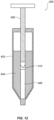
- FIG. 1 depicts an exemplary delivery device (e.g., a syringe).
- a delivery device e.g., a syringe
- FIG. 2 depicts an exemplary pawl and ratchet mechanism for a delivery device.
- FIGS. 3A and 3B depict an exemplary lock mechanism for a delivery device.
- FIGS. 3C and 3D depict an exemplary telescoping mechanism for a delivery device.
- FIGS. 4A and 4B depict exemplary rotational lock mechanisms for a delivery device.
- FIGS. 4C-4E depict an exemplary delivery device with an exemplary rotational lock mechanism in various positions.
- FIG. 5 depicts an exemplary delivery device.
- FIGS. 6A-6E depict an exemplary delivery device and locking mechanism.
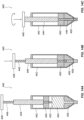
- FIG. 7A depicts an exemplary delivery device.
- FIG. 7B depicts a threaded portion of the delivery device of FIG. 7A .
- FIG. 8 depicts an alternative of the threaded portion of FIG. 7B .
- FIG. 9A depicts an exemplary delivery device.
- FIGS. 9B-9D depict locking components of the delivery device of FIG. 9A .
- FIGS. 10A-10C depict further exemplary delivery devices.
- FIGS. 11A and 11B depict still further exemplary delivery devices.
- FIG. 12 depicts an exemplary delivery device.
- FIGS. 13A-13C depict an exemplary priming and delivery mechanism for a delivery device.
- FIGS. 14A-14C depict another exemplary priming and delivery mechanism for a delivery device.
- FIGS. 15A-15E depict another rotational lock mechanism for a delivery device.
- FIGS. 16A-16E depict another exemplary delivery device and lock mechanism.
- FIGS. 17A-17C depict further exemplary delivery devices and mechanisms e.
- FIGS. 18A-18F depict a locking and priming mechanism for a delivery device.
- FIGS. 19A-19E depict another locking and priming mechanism for a delivery device.
- the embodiment of Fig. 19A shows an embodiment according to the invention.
- FIGS. 20A-20C depict another locking and priming mechanism for a delivery device.
- the terms “comprises,” “comprising,” “includes,” “including,” or any other variation thereof, are intended to cover a non-exclusive inclusion, such that a process, method, article, or apparatus that comprises a list of elements does not include only those elements, but may include other elements not expressly listed or inherent to such process, method, article, or apparatus.
- Drug products may include one or more active ingredients, including, e.g., small or large molecules or biologics, such as pain medications, steroids, or biologics.
- active ingredients including, e.g., small or large molecules or biologics, such as pain medications, steroids, or biologics.
- biologics may refer to a large molecule (e.g., having a size greater than 15 kDa, greater than 30kDa, greater than 50kDa, greater than 75 kDa, or greater than 100 kDa) created in a living system such as a cell.
- Biologics may include proteins (e.g., antibodies), nucleic acids, large sugars, etc.
- drug product may refer to a volume of a formulated drug substance apportioned into a primary packaging component for packaging, transportation, delivery, and/or administration to a patient.
- primary packaging component refers to a packaging component for a drug product, such as a drug container, that is designed and manufactured to be in direct physical contact with the formulated drug substance.
- a drug product such as a drug container
- Examples of primary packaging components include prefillable syringes, Luer syringes, cartridges, and vials made of glass, plastic, and/or other materials.
- the present disclosure may be used with products typically having small dose volumes, such as, e.g., ophthalmic drug products.
- devices of the present disclosure may be used with drug products including an antigen-binding molecule.
- the antigen-binding molecule may be an antibody or antigen-binding fragment.
- devices of the present disclosure may be suitable for use with drug products including ingredients such as, e.g., aflibercept, alirocumab, abicipar pegol, bevacizumab, brolucizumab, conbercept, dupilumab, evolocumab, tocilizumab, certolizumab, abatacept, rituximab, infliximab, ranibizumab, sarilumab, adalimumab, anakinra, trastuzumab, pegfilgrastim, interferon beta-1a, insulin glargine [rDNA origin], epoetin alpha, darbepoetin, filigrastim, golimumab, etanercept, antigen-binding fragments of any of the above, or combinations of such binding domains, such as a bispecific antibody to VEGF or angiopoietin-2, among others.
- ingredients such as
- dose accuracy may be particularly important.
- embodiments of the present disclosure may be applicable to any other liquid products or any other context for which precise methods for setting and administering a reliably accurate dose or delivery volume are beneficial.
- Devices according to the present disclosure may be manufactured, packaged, filled, and/or otherwise prepared according to processes relevant to the products (e.g., drug products) they may be used with.
- devices according to the present disclosure may be sterilized, either before or after being filled and/or packaged.
- devices according to the present disclosure may be filled and packaged in, e.g., blister packaging, and/or may be terminally sterilized using any suitable method in the art.
- devices according to the present disclosure may be terminally sterilized using a chemical sterilization method, such as a method including ethylene oxide or hydrogen peroxide (e.g., vaporized hydrogen peroxide).
- Devices according to the present disclosure may be terminally sterilized using methods described in, e.g., International Application No. PCT/US2018/021013, filed March 6, 2018 .
- Dose delivery devices available on the market may not necessarily assist with accurately loading a desired volume of a product, priming the devices, expelling excessive drug product from the devices, and/or removing air bubbles from the devices.
- a small volume of a drug product in particular e.g., about 500 ⁇ L or less, about 300 ⁇ L or less, about 250 ⁇ L or less, about 200 ⁇ L or less, about 150 ⁇ L or less, about 100 ⁇ L or less, about 50 ⁇ L or less, or about 25 ⁇ L or less, such as between about 25 ⁇ L and about 50 ⁇ L, between about 50 ⁇ L and about 100 ⁇ L, between about 25 ⁇ L and about 100 ⁇ L, between about 50 ⁇ L and about 150 ⁇ L, between about 100 ⁇ L and about 250 ⁇ L, between about 100 ⁇ L and about 150 ⁇ L, between about 150 ⁇ L and about 250 ⁇ L, between about 200 ⁇ L and about 250 ⁇ L, between about 200 ⁇ L and about 500 ⁇ L, or between about 250 ⁇ L and about 500 ⁇ L), it may also be difficult to confirm the presence of the correct dose of a drug product in the device with the naked eye.
- a syringe e.g., a prefilled or fillable/refillable syringe
- prime the syringe remove air bubbles from the syringe
- the present disclosure may assist manufacturers, drug product providers, medical professionals, and/or patients with accurately filling or otherwise preparing a dose administration device, priming the device, removing bubbles from the device, confirming the dose, and/or administering a dose from the device to a patient.
- embodiments of the present disclosure may assist in preventing or mitigating errors or variation in device manufacture or use, such as errors or variation in placement of dose lines on devices, variation in device geometry (e.g., variation in syringe neck geometry), and/or variation or errors in setting a dose line prior to delivery of a product.
- errors or variation in device manufacture or use such as errors or variation in placement of dose lines on devices, variation in device geometry (e.g., variation in syringe neck geometry), and/or variation or errors in setting a dose line prior to delivery of a product.
- the present disclosure may be of particular assistance to individuals who may have difficulty setting doses with precision and accuracy.
- the present disclosure may assist elderly individuals, young children, or persons with physical or mental disabilities in setting accurate doses.
- Described herein are various dose delivery devices, and in particular, for syringes.
- embodiments disclosed herein may be used in conjunction with existing syringe body parts to modify off-the-shelf products, which may reduce the development and manufacturing time for the dose delivery devices.
- embodiments disclosed herein may be included in devices during their manufacture.
- the syringes described herein may be prefilled or may be fillable/refillable.
- the present disclosure may include syringes having rotating parts, threaded parts, springs, gears, and the like, that may allow a user to precisely control the movement of dosage setting and delivery elements such as, e.g., plungers and/or stoppers.
- dosage setting and delivery elements such as, e.g., plungers and/or stoppers.
- screw and gear mechanisms may be used to transfer rotary motion (e.g., on a knob or dial) to linear motion of a plunger, and thus to set the plunger rod of a syringe to a predefined position with reduced human effort and/or relatively greater accuracy.
- rotary motion e.g., on a knob or dial
- linear motion of a plunger e.g., on a knob or dial
- embodiments of the present disclosure may reduce human error as well.
- Visualization devices such as magnifiers
- Devices according to the present disclosure may be depicted as including one type of plunger rod and plunger, or as including a general schematic representation of a plunger rod and plunger.
- some devices according to the present disclosure may be depicted or described as including, e.g., a plunger rod having a threaded end, which engages with threads on an interior of a plunger such that the plunger rod and the plunger may be screwed together.
- a plunger rod having a threaded end which engages with threads on an interior of a plunger such that the plunger rod and the plunger may be screwed together.
- multiple and/or different configurations of plunger rods and plungers may be appropriate for each of the embodiments disclosed herein.
- the aforementioned threaded plunger rod and plunger may be used with embodiments disclosed herein.
- a plunger rod may not be affixed to a plunger, and instead may be disposed near, next to, or flush against a plunger such that pressure from the plunger rod towards the plunger may push the plunger, but withdrawal, twisting, or other movement of the plunger rod may not cause the plunger to likewise be withdrawn, twisted, or otherwise moved.
- a plunger rod may be affixed to a plunger by an adhesive, or may be of a single piece with a plunger (e.g., may have been manufactured in a single mold with a plunger).
- Devices according to the present disclosure may include various cosmetic features relevant to intended users of the devices.
- devices according to the present disclosure may be manufactured and sold for use by pediatric patients.
- devices according to the present disclosure may include child-friendly coloring, cartoon images, or other cosmetic features to appeal to children.
- devices according to the present disclosure may include lettering, labeling, or other features designed to be easily recognized by the intended users. For example, lettering on a pediatric device or a device for use by a disabled person or an elderly person may have larger, more accessible labeling so that it may be more easily recognized and read by the user(s) of the device.
- FIG. 1 depicts a syringe 10 containing a volume of drug product 12 and having a dose expel control mechanism.
- the dose expel control mechanism may include a rack 2 and a pinion 3.
- Rack 2 may be formed on an inner surface of a plunger rod 1 of syringe 10 or may be otherwise attached to an inner surface of plunger rod 1.
- rack 2 may, e.g., be engraved, machined, or molded onto plunger rod 1.
- Rack 2 may include a plurality of teeth extending along its length.
- Pinion 3 may also include a plurality of teeth that are configured to engage with the teeth of rack 2.
- Pinion 3 may be operably connected to an actuator (e.g., a dial or a knob) located external to plunger rod 1 via a pinion rod 4.
- an actuator e.g., a dial or a knob
- rotation of a dial 5 may cause rotation of pinion rod 4 and thus rotation of pinion 3.
- pinion rod 4 may extend from an interior region of syringe 10 (where it connects to pinion 3) to an exterior region of syringe 10 (where it connects to dial 5).
- pinion rod 4 may extend partially or fully through a finger flange 7 (e.g., on, integral to, or affixed to syringe 10).
- Pinion rod 4 may extend through a body wall of plunger rod 1 and/or syringe barrel 9 of syringe 10. Pinion rod 4 may be supported by a gasket or seal, such as an O-ring 6, where it exits finger flange 7 (or, if appropriate, syringe barrel 9). O-ring 6 may provide physical support to pinion rod 4 and/or pinion 3 while pinion 3 is in motion and/or at rest. While O-ring 6 is described as providing structural support to pinion rod 4 and/or pinion 3, it is also contemplated that O-ring 6 may simply seal the internal region of plunger rod 1 from an external region, or both.
- a gasket or seal such as an O-ring 6, where it exits finger flange 7 (or, if appropriate, syringe barrel 9).
- O-ring 6 may provide physical support to pinion rod 4 and/or pinion 3 while pinion 3 is in motion and/or at rest. While O-ring 6 is described as providing structural support to pinion rod 4
- seals or gaskets may be used instead of, or in addition to, O-ring 6, and these seals or gaskets may or may not provide structural support and/or sealing.
- seals or gaskets may simply provide a barrier protecting the interior region of syringe from an exterior region or may provide structural support and may also act as a barrier.
- Teeth of pinion 3 may engage with teeth of rack 2 such that, upon rotation of pinion 3 via dial 5, the rotational motion of pinion 3 may cause translational motion of plunger rod 1.
- rotating pinion 3 may cause plunger rod 1 to move distally and/or proximally in syringe barrel 9, which may also move piston 8 (e.g., a stopper) within syringe barrel 9.
- piston 8 (which may also act as a stopper) within syringe barrel 9 may be gradually moved towards the needle end of syringe 10, so that air and excess drug may be pushed out through needle 13, priming needle 13 for injection of an appropriate dose of drug product 12.
- Pinion 3 and rack 2 may be sized and configured such that rotation of pinion 3 in a given direction or by a given amount (e.g., one clockwise rotation) may cause rack 2 and pinion 3 to disengage from one another, which may cease the ability of dial 5 to advance piston 8.
- rack 2 and/or pinion 3 may cease to move.
- pinion 3 may be prevented from moving further as a result of reaching a proximal end of rack 2, as a result of disengaging with rack 2, as a result of disengaging with pinion rod 4, as a result of abutting against a stopper, or dial 5 may only be rotatable for a given amount. Accordingly, rotation of dial 5 and pinion 3 a given amount in a given direction may serve to complete priming of the syringe needle.
- Pulling out dial 5 may lock it in place, thereby preventing further movement of plunger rod 1 via use of dial 5Pulling dial 5 outwards may unlock the outer plunger rod, allowing it to move freely, whether or not movement of dial 5 is locked Pulling dial 5 and/or pinion rod 4 outward may disengage pinion 3 from rack 2. In some embodiments, a user may not be able to depress plunger rod 1 until pinion 3 reaches its terminal position and/or until dial 5 is pulled outwards.
- Dial 5 may be the only mechanism capable of moving plunger rod 1 until syringe 10 has been primed.
- the complementary teeth of rack 2 and pinion 3 may prevent a user from depressing plunger rod 1 (and/or pulling plunger rod 1 proximally) until pinion 3 has disengaged from rack 2. This may prohibit drug product 12 from being dispensed until syringe 10 has been primed and may inhibit under- or over-priming of syringe 10 and promote accurate dispensation of drug product 12.
- syringe 10 may optionally include a magnifier 11 attached to or embedded on syringe barrel 9.
- Magnifier 11 may aid in reading measurement indicators on syringe barrel 9, may aid in observing the presence or absence of air bubbles in syringe barrel 9, and/or may aid in determining whether a complete dose of drug product 12 has been dispensed from syringe 10.
- Magnifier 11 may be included in a distal region of syringe 10 and may be any suitable shape or size.
- magnifier 11 may have a circular or rectangular shape or may wrap around all of or a portion of the circumference of syringe barrel 9No magnifier 11 may be included.
- Dial 5 may be rotated a given amount in a given direction until rotation of pinion 3 stops.
- a user may detect whether pinion 3 has stopped when dial 5 is unable to rotate further and/or when movement of plunger rod 1 ceases.
- pinion 3 may stop moving, e.g., as a result of reaching an end region of rack 2, as a result of disengaging with rack 2, as a result of disengaging with pinion rod 4, as a result of abutting against a stopper, or because dial 5 may only be rotatable for a given amount.
- dial 5 may be pulled outwards by a user to prevent further movement of plunger rod 1 via dial 5.
- a user may optionally confirm the dose level of drug product in syringe barrel 9 and/or may optionally confirm whether any air is trapped within syringe barrel 9. A proximal end of plunger rod 1 may then be pushed to inject a dose of drug product.
- FIG. 2 depicts an exemplary variation on the pinion 3 depicted in FIG. 1 .
- Pinion 20 of FIG. 2 may include an internal ratchet and pawl mechanism to allow rotation of pinion 20 in a first direction and to prevent rotation of pinion 20 in a second direction, opposite the first direction. For example, only clockwise rotation may be allowed and counterclockwise rotation may be blocked, or vice versa. Pinion 20 may be prevented from rotating in a direction that would cause plunger rod 1 to move proximally away from the needle end of syringe 10, while rotation in a direction that would cause plunger rod 1 to move distally towards the needle end of syringe 10 is allowed.
- ratchet 23 may be coaxial with pinion 20, and dial 5 ( FIG. 1 ) may be connected to ratchet 23, for example, via a pinion rod (such as pinion rod 4 depicted in FIG. 1 ) through a center 25 of ratchet 23.
- Ratchet 23 may include angled teeth 24.
- An interior region of pinion 20 may include a spring-loaded pawl 22 operably coupled to the interior region.
- Pawl 22 may be positioned at an angle complementary to the angles of ratchet teeth 24 and close enough so that a free end of pawl 22 engages ratchet teeth 24.
- Each ratchet tooth 24 may include a rounded surface, over which the free end of each pawl 22 can slide, and a projecting face against which the free end of each pawl 22 may engage and be stopped.
- Rotation of dial 5 of FIG. 1 in one direction e.g., a direction that would cause plunger rod 1 to move away from the needle end of syringe 10) may cause rotation of ratchet 23 such that ratchet teeth 24 do not engage pawls 22, and ratchet 23 may rotate independently of pinion 20.
- Rotation of dial 5 in the opposite direction may cause ratchet 23 to engage with pawls 22 and to rotate pinion 20 such that plunger rod 1 and piston 8 may move distally towards the needle end of the device, allowing for priming of needle 13 and expulsion of air.
- FIGS. 3A and 3B depict another variation of the pinion 3 depicted in FIG. 1 .
- Plunger rod 30 may include a rack 32 extending along at least a portion of its length.
- Rack 32 may include a plurality of teeth 34 configured to engage with teeth 36 on pinion 33.
- pinion 33 may include a stopper tooth in the form of protrusion 35.
- Protrusion 35 may extend radially further out from pinion 33 than teeth 36 and may have a height that is greater than a height of teeth 36.
- Pinion 33 may rotate along rack 32 ( FIG. 3A ) until protrusion 35 on pinion 33 contacts rack 32 or plunger rod 30 ( FIG. 3B ), halting rotation of pinion 33.
- protrusion 35 may prevent more than one rotation of pinion 33. Halting rotation of pinion 33 may consequently halt advancement of plunger rod 30 and piston 38 beyond a predetermined point.
- the predetermined point may correspond to, e.g., a point at which excess air and dosage of a drug product may be expelled from syringe 10 (see FIG. 1 ), resulting in accurate priming of syringe 10.
- protrusion 35 contacts plunger rod 30 and pinion 33 assumes the position shown in FIG. 3B , protrusion 35 may be free of rack 32, and plunger rod 30 may slide freely against it. Accordingly, in FIGS. 3A and 3B , instead of the rack length controlling the amount of movement of plunger rod 30 is allotted to prime the syringe, the circumference of pinion 33 may control this movement.
- protrusion 35 on pinion 33 may also provide tactile feedback to a user to indicate that a proper dose has been set and that syringe 10 has been primed. Inclusion of protrusion 35 on pinion 33 may additionally prevent over- or under-rotation of pinion 33 in an undesirable direction (e.g., that would allow movement of plunger rod in a proximal direction). Protrusion 35 may be useful to prevent overfilling of syringe 10 or intake of air into syringe 10 during handling, packaging, storage, and/or transport. A protrusion 35 may be located on rack 32 instead of, or in addition to, pinion 33 to control movement of pinion 33.
- FIGS. 3C and 3D depict another variation of plunger rod 1 depicted in FIG. 1 .
- Plunger rod 40 of FIGS. 3C and 3D may include a locking mechanism configured to prevent accidental depression of piston 48, e.g., when the syringe is being packaged, stored, handled, and/or filled.
- Plunger rod 40 may include a telescoping inner portion 49 (e.g., an inner tubular portion or a column) having a rack 42.
- Inner portion 49 of plunger rod 40 may include piston 48 connected to a distal end thereof.
- Inner portion 49 may move relative to a stationary outer portion 41 (e.g., an outer lumen).
- Rotation of dial 45 may extend inner portion 49 distally out from outer portion 41 so that inner portion 49 moves independently from outer portion 41.
- Dial 45 may be operably connected to the telescoping inner portion 49 by pinion rod 44 (e.g., a shaft) and pinion 43. Rotation of dial 45 may in turn rotate piston rod 44 and pinion 43. Teeth on pinion 43 may engage with teeth on rack 42 of inner portion 49, moving inner portion 49 distally out from outer portion 41.
- FIG. 3C depicts inner portion 49 of telescoping plunger rod 40 retracted within outer portion 41
- FIG. 3D depicts inner portion 49 of telescoping plunger rod 40 extending out from outer portion 41. Turning dial 45 may thus move piston 48 distally towards the needle end of the syringe to prime the needle and remove air bubbles.
- plunger rod 40 While inner portion 49 of plunger rod 40 may extend from outer portion 41 during priming of the needle, outer portion 41 may not move during dose preparation. Dial 45 and/or pinion rod 44 may optionally interfere with outer portion 41 of plunger rod 40 so that plunger rod 40 can't move relative to the syringe barrel and can't be depressed by pressing on thumbpad 47 of plunger rod 40 during dose preparation.
- pinion rod 44 may extend through an opening of telescoping outer portion 41 of plunger rod 40.
- extension of pinion rod 44 through a sidewall of outer portion 41 may prevent movement of outer portion 41. Because outer portion 41 cannot be moved, plunger rod may not be able to be depressed.
- Pulling out dial 45 may disengage pinion rod 44 from pinion 43, so that pinion rod 44 no longer extends through outer portion 41.
- pinion rod 44 may be removed from engagement with the telescoping portions and may no longer extend through the telescoping portions, allowing plunger rod 40 may to move freely within the syringe barrel. Movement of plunger rod 40 in a distal direction by pressing thumbpad 47 may allow for administration of the dose.
- telescoping inner portion 49 of plunger rod 40 may be fixed in place relative to outer portion 41 so that depressing thumbpad 47 and moving plunger rod 40 does not cause telescoping inner portion 49 to collapse back within outer portion 41.
- Outer portion 41 and inner portion 49 of plunger rod 40 may, for example, be coupled to each other with positive locking teeth (e.g., teeth 46 of outer portion 41), which may allow inner portion 49 to extend distally from outer portion 41 but may prohibit backwards movement of inner portion 49 into outer portion 41. This may prevent the two telescoping portions from collapsing one into the other when thumbpad 47 is depressed and plunger rod 40 moves distally to expel the dose. This may also prevent proximal movement of inner portion 49 during priming.
- dial 45 may be rotated to prime a syringe as depicted in FIGS. 3C and 3D and may allow for finer and/or more controlled movements of plunger rod 40 for such priming. As described above, the inclusion of dial 45 may prevent discharge of any product volume intended for dosage until priming is complete and, e.g., dial 45 has been pulled outwards to unlock movement of plunger rod 40.
- any suitable type of locking mechanism may be incorporated, and that such a locking mechanism may be activated and/or deactivated by pulling, depressing, sliding, or otherwise manipulating dial 45.
- FIGS. 4A and 4B depicted in cross section in FIGS. 4A and 4B , an embodiment not according to the invention.
- the locking mechanisms of FIGS. 4A and 4B may be used instead of, or in addition to, dial 45 of FIGS. 3C and 3D .
- the entirety of plunger rod 50 or a proximal region of plunger rod 50 may include a physical stop (e.g., an interfering bump or projection) to prevent depression of plunger rod 50 during dose preparation and priming-or to allow only enough depression to prepare and prime the dose.
- a physical stop e.g., an interfering bump or projection
- an interfering projection 51 may prevent plunger rod 50 from moving distally until plunger rod 50 and/or the portion of plunger rod 50 having projection 51 is rotated relative to other portions of the syringe, e.g., a finger flange (not shown), a stopper 53 located at a mouth of a syringe barrel 58, and/or syringe barrel 58.
- a finger flange not shown
- stopper 53 located at a mouth of a syringe barrel 58
- syringe barrel 58 e.g., a stopper 53 located at a mouth of a syringe barrel 58, and/or syringe barrel 58.
- plunger rod 50 as a whole may have a cross-sectional shape that is not radially symmetrical, such that the shape of plunger rod 50 may prevent it from moving distally until plunger rod 50 is rotated relative to other portions of the syringe, e.g., a finger flange, stopper 53, and/or syringe barrel 58.
- plunger rod 50, stopper 53, and/or barrel 58 may be rotated relative to other portions of the syringe in order to be able to depress plunger rod 50 enough to fully dispense the drug dose.
- Plunger rod 50 may not be capable of moving past, e.g., a finger flange or stopper 53 in the syringe barrel until plunger rod 50 is rotated a certain number of degrees (e.g., 90 degrees) in relation to the finger flange or the stopper.
- the finger flange or stopper 53 may be rotated (e.g., 90 degrees) in relation to plunger rod 50.
- plunger rod 50 may have a particular cross-sectional shape (e.g., a generally rectangular shape and/or projections 51), and syringe barrel 58 and/or stopper 53 may include a blocking component and/or may be sized and shaped so that projections 51 of plunger rod 50 cannot fit through until the relevant parts have been rotated sufficiently so that the complementary shapes align and plunger rod 50 can pass through.
- a particular cross-sectional shape e.g., a generally rectangular shape and/or projections 51
- syringe barrel 58 and/or stopper 53 may include a blocking component and/or may be sized and shaped so that projections 51 of plunger rod 50 cannot fit through until the relevant parts have been rotated sufficiently so that the complementary shapes align and plunger rod 50 can pass through.
- An opening 52 in stopper 53 and/or syringe barrel 58 (and/or a finger flange, not shown), and a cross-section of plunger rod 50 may have complementary shapes but may be offset from each other unless one or the other is rotated until the shapes align.
- projections 51, or the general shape of plunger rod 50 do not align with opening 52 until the finger flange or plunger rod 50 is rotated sufficiently. While two projections 51 from plunger rod 50 and a corresponding shape of opening 52 are depicted in FIG. 4A , and while a given cross-sectional shape of plunger rod 50 is depicted in FIG.
- any suitable number, size, and shaped openings and projections and/or cross-sectional shapes may be used. Additionally, while exemplary it is shown that the required rotation as being 90 degrees, it is contemplated that any suitable amount of rotation (less than or greater than) 90 degrees may be needed.
- FIGS. 4C-4E depict a side view of a syringe 54 having plunger rod 50, with projections 51, in three different positions.
- Syringe 54 may include stopper 53, through which projections 51 cannot fit until projections 51 and stopper 53 have been rotated relative to one another such that the shape of projections 51 fits a complementary opening in stopper 53 (see, e.g., dotted lines in FIG. 4A ).
- Plunger rod 50 may be coupled to a plunger 56, which may be configured to fit snugly within a barrel 58 of syringe 54.
- Syringe 54 may include a volume of a drug product 12 suitable for dispensing from syringe 54.
- syringe 54 is depicted in a first, un-actuated position. Projections 51 are positioned about plunger rod 50 in a first orientation. In FIG. 4D , syringe 54 is depicted in a second, partially actuated position. Projections 51 in the first orientation are blocked from passing through stopper 53, and thus the further depression of plunger rod 50 is also blocked. In FIG. 4E , syringe 54 is depicted in a fully actuated position. Upon rotation of plunger rod 50 (e.g., in the manner indicated by the curved arrow, or alternately in the opposite direction), projections 51 may be moved into a second orientation about plunger rod 50. In the second orientation, projections 51 may pass through stopper 53, allowing for further depression of plunger rod 50 and plunger 56.
- Projections 51 may be positioned on plunger rod 50 such that they do not protrude from the general profile of syringe 54.
- projections 51 may be located inside, e.g., barrel 58 before syringe 54 is actuated (e.g., in FIG. 4C ).
- Projections 51 may be located, e.g., inside a portion of stopper 53 before syringe 54 is actuated.
- Stopper 53 may have a greater thickness so as to accommodate projections 51, and may have a proximal cavity sized and configured to house projections 51 in a first orientation, and a more distal cavity configured to accommodate projections 51 in a second orientation, such that rotation of plunger rod 50 and/or projections 51 may allow for movement of plunger rod 50 in a distal direction.
- a second set of projections may be incorporated in plunger rod 50 either proximally or distally from projections 51.
- the second set of projections may have similar geometry to projections 51, but may be radially offset from projections 51, such that additional rotation of plunger rod 50 is required for the second set of projections to pass through an opening in, e.g., stopper 53 (e.g., opening 52).
- a second set of projections may have a geometry that cannot fit through an opening, such that plunger rod 50 is inhibited from moving in a given direction by their geometry.
- Such a second set of projections may be useful in, e.g., limiting movement of plunger rod 50 either before or after projections 51 have passed through the opening.
- Limiting of movement in this manner may be used in controlling an amount of movement of plunger rod 50 allowed for priming syringe 10, prior to further rotation of plunger rod 50 to allow for dispensing a dosage amount from syringe 10Limiting of movement in this manner may be used to control a dosage volume that may be dispensed from syringe 50. See, for example, FIGS. 15A-E described further below. As is the case with all embodiments depicted and described herein, this embodiment may be combined with aspects of other embodiments described herein.
- the syringe may be configured to provide feedback to the user to indicate when rotation of plunger rod 50 and projections 51 and/or the finger flange is complete and plunger rod 50 is aligned with openings 52 (see FIGS. 4A-4B ).
- a "clicking" noise or other audio or tactile feedback mechanism may be incorporated into the syringe.
- FIGS. 6A-6E include a locking mechanism to prevent accidental depression of plunger rod 71 when priming of the needle is complete.
- the device of FIGS. 6A-6E includes threads 72 on plunger rod 71, which must be twisted through corresponding threads 73 of syringe barrel 75.
- plunger rod 71 may also include a stop 74 located on an outer surface of plunger rod 71, proximal to threads 72.
- Stop 74 may be sized and shaped to fit within a slot 76 extending through threads 73.
- stop 74 may enter a vertical portion of slot 76 passing through some of internal threads 73 of syringe barrel 75 (depicted in, e.g., section A-A in FIGS. 6B and 6C ).
- Slot 76 may also include a horizontal section (e.g., along section B-B depicted in FIGS. 6B and 6D ).
- plunger rod 71 may be depressed downwards to move stop 74 through a second vertical section of slot 76 (e.g., section C-C depicted in FIGS. 6B and 6E ), to expel a volume of the drug product.
- Slot 76 may be shaped to require clockwise or counterclockwise rotation, depending on the relative locations of the horizontal and vertical sections. Additionally, although slot 76 is shown and described as including one horizontal portion requiring rotation of rod 71, it is contemplated that multiple horizontal portions may be included, requiring rod 71 to be rotated addition times in the same direction or in multiple directions. Further, although stop 74 is depicted as including two projections on plunger rod 71, it is contemplated that one projection or more than two projections may be included as part of stop 74, and slot 76 may be shaped and sized to accommodate the different configurations of stop 74.
- threads 73 are described as being on an internal surface of syringe barrel 75, it is contemplated that threads 73 and slot 76 may be located on an internal surface of a finger flange instead of, or in addition to, syringe barrel 75. Moreover, as is the case with all embodiments depicted and described herein, the above-described embodiment may be combined with aspects of other embodiments described herein.
- rod 71 may include additional projections and/or geometries, such as those shown in FIGS. 4A-4E and FIGS. 15A-15E , to provide a hard stop to the movement of rod 71.
- syringe 80 includes complementary helical threads 82 and 83. External threads 82 are located on a sleeve 87 surrounding plunger rod 81 instead of directly on plunger rod 81. A close-up of the threaded portions of syringe 80 is depicted in FIG. 7B .
- Sleeve 87 may allow for free distal movement of plunger rod 81 (towards the needle end of syringe 80), but may block undesirable proximal movement of piston 88.
- rotation of sleeve 87 (e.g., via twisting of dial rod 85 located at a proximal end of sleeve 87) may be transformed into a controlled sliding movement of sleeve 87 into syringe barrel 89 via threads 82 on sleeve 87 and corresponding threads on finger flange 84 and/or syringe barrel 89.
- the controlled sliding movement of sleeve 87 may gradually push plunger rod 81 and stopper 88 towards the distal needle end of the device. Movement of plunger rod 81 through the threaded region may allow for controlled expulsion of air and priming of needle 86.
- the device of FIG. 7A may also optionally include a magnifier 90.
- Magnifier 90 may magnify volume measurements of the drug product in syringe barrel 89, may aid in observing the presence or absence of air bubbles in syringe barrel 89, and/or may aid in determining whether a complete dose of drug product has been dispensed from syringe 80.
- Magnifier 90 may be included in a distal region of syringe 80 and may be any suitable shape or size.
- magnifier 90 may have a circular or rectangular shape or may wrap around all of or a portion of the circumference of syringe barrel 89. No magnifier 90 may be included.
- dial rod 85 may be rotated a partial rotation, one complete rotation, or more than one complete rotation in order to pass threads 82 of sleeve 87 through threads 83 until threads 82 are disengaged from threads 63.
- a user may optionally confirm the dose level in syringe barrel 89.
- the user may use magnifier 90 to perform this step, if magnifier 90 is included.
- the user may then push plunger rod 81 to dispense the dose of drug product.
- Syringe 80 may provide feedback to the user to indicate when rotation of plunger rod 81 is complete and the dose is ready for injection. For example, a "clicking" noise or other audio or tactile feedback mechanism may be incorporated into syringe 80. A user may know that priming is complete because dial rod 85 may not rotate any further, plunger rod 81 may not move any further when twisting, and/or dial rod 85 may abut a portion of finger flange 84 and/or syringe barrel 89, preventing further distal movement of dial rod 85.
- a locking mechanism like the one discussed above in reference to FIGS. 6A-6E may be incorporated into plunger rod 81.
- plunger rod 81 By requiring that plunger rod 81 be turned (e.g., 90 degrees, although turning plunger rod 81 more or less is than 90 degrees is also contemplated) prior to administration to allow plunger rod 81 to move freely, plunger rod 81 may be prevented from being pressed in a distal direction during needle priming.
- a locking or stopping mechanism may be incorporated into sleeve 87 of FIGS. 7A and 7B , not according to the invention. Such a mechanism is depicted in FIG. 8 .
- stops 91 and/or 92 e.g., tabs or projections
- sleeve 87 e.g., at positions above and/or below threads 82 on sleeve 87 and threads 83 in the syringe barrel
- over-rotation of the sleeve in either direction and thus over-priming or unwanted removal of sleeve 87 may be prevented.
- Stop 91 may be located proximal of threads 82 and may be configured to stop movement of sleeve 87 towards the distal end region of the syringe barrel.
- Stop 92 may be located distally from threads 82 and may be configured to stop movement of sleeve 87 towards the proximal end region of the syringe barrel.
- FIGS. 9A-9D another syringe 100 is pictured with a dose expel control mechanism.
- This syringe may include, for example, a key 103 to act as a removable stop at a junction between syringe barrel 109 and plunger rod 101.
- Key 103 may obstruct movement of plunger rod 101 when it is in place between syringe barrel 109 and a proximal region of plunger rod 101.
- Key 103 may be placed between plunger rod 101 and syringe barrel 109, e.g., during packaging, filling, or preparation of syringe 100.
- Key 103 may snap-fit, friction-fit, twist-fit, or otherwise be set in place in any suitable manner.
- Syringe 100 is depicted as having a magnifier 105 disposed at a distal end portion of syringe barrel 109, which may assist in, e.g., visualizing a level of product in barrel 109.
- key 103 may prevent the accidental depression of plunger rod 101 prior to its intended use, thus preserving the sterility, safety, and dose volume of the drug product.
- Variations of key 103 may include, for example, a frangible stop that may be broken by applying a certain amount of force to plunger rod 101.
- FIG. 9A may include a locking mechanism similar to that discussed with respect to, e.g., FIGS. 4A-4E , above, or FIGS. 15A-E , described further herein.
- a slot 107 may be included in a stopper 104 of syringe 100.
- Stopper 104 may have an open portion 110 through which plunger rod 101 may move without being rotated to a set position.
- the open portion 110 may allow the plunger to move a distance suitable for priming needle 106.
- Slot 107 may be sized and shaped to fit the cross-sectional area of plunger rod 101 in a particular orientation.
- plunger rod 101 may include a flange 102 sized and shaped to pass through slot 107 when aligned with slot 107.
- Stopper 104 may be disposed at a proximal region of syringe barrel 109, such that plunger rod 101 must be rotated to a set position to align flange 102 with slot 107 prior to being depressed through at least part of stopper 104.
- flange 102 and corresponding slot 107 are depicted, slot 107 and plunger rod 101 may have any suitable complementary cross-sectional shapes.
- plunger rod 101 may have multiple cross-sectional geometries along its length, to either provide a hard stop to distal movement of plunger rod 101 or require additional turning of plunger rod 101 relative to stopper 104 to further move plunger rod 101 (see, e.g., FIGS. 15A-15E ). As is the case with all embodiments depicted and described herein, this embodiment may be combined with aspects of other embodiments described herein.
- plunger rod 101 may be allowed to move distally from its original position down through open portion 110 of stopper 104. This distal movement of plunger rod 101 may move piston 108 just enough to prime needle 106 and to remove any air bubbles. Stopper 104 may halt additional distal movement of plunger rod 101 when flange 102 hits the inner portion of stopper 104, where slot 107 begins. At that time, plunger rod 101 may need to be rotated to align flange 102 with slot 107 in stopper 104 before rod 101 can be pushed distally through the rest of stopper 104 to move piston 108 and discharge the drug dose.
- Syringe 100 may be configured to provide feedback to the user to indicate when plunger rod 101 and flange 102 are aligned with slot 107 and/or when priming of syringe 100 is complete. For example, a "clicking" noise or other audio or tactile feedback mechanism may be incorporated into syringe 100.
- FIGS. 10A-10C a cross-sectional image of a syringe 200 is depicted, with various dose expel control mechanisms.
- Syringe 200 may include a barrel 240 and a plunger rod 220.
- Plunger rod 220 may be coupled to a first plunger 222, which may be configured to fit into an opening in a flange 210 positioned at a proximal plunger rod end of barrel 240.
- Flange 210 may be configured to fit securely within barrel 240, and may be, e.g., sealed against an interior of barrel 240 with an O-ring 208.
- the interior of barrel 240 may include a second plunger 260 configured to fit snugly within the interior of barrel 240.
- a first fluid 244 may be disposed inside barrel 240 to a proximal side of plunger 260, and a second fluid, e.g., a drug product 212, may be disposed inside barrel 240 to a distal side of plunger 260.
- a needle, cannula, tube, or other attachment may be coupled to a distal end of barrel 240, through which a fluid, e.g., drug product 212, may be expelled or withdrawn.
- the opening of flange 210 may have a cross-sectional width a into which plunger 222 may be configured to securely fit.
- Plunger 222 may be configured to form a seal against flange 210, e.g., with the use of an O-ring 224.
- the portion of flange 210 having width a may also have a depth c. As shown in FIG. 10A , depth c may correspond to a distance between a distal side of plunger 222 and a distal side of flange 210.
- Distal movement of plunger 222 for, e.g., a distance corresponding to depth c may cause a first volume of fluid 244 in the opening of flange 210 to be displaced distally by a distance corresponding to depth c. Displacement of the first volume of fluid 244 may in turn push plunger 260, causing a second volume of drug product 212 to be expelled from syringe 200.
- Barrel 240 may have a cross-sectional width b located distally from flange 210, where width b is greater than width a.
- distal movement of plunger 222 by, e.g., a distance corresponding to depth c may cause plunger 260 to move distally by a smaller distance d.
- a movement of, e.g., plunger rod 220 in the distal (or proximal) direction may be converted into a proportionally smaller, and thus more controllable, movement of plunger 260 and thus a more controllable expulsion (or withdrawal) of a volume of drug product 212.
- FIGS. 10B and 10C may differ somewhat from FIG. 10A .
- cross-sectional widths a and b may both be widths of an opening in flange 210A
- second plunger rod 262 may be disposed within the barrel, such that a portion of plunger rod 262 is disposed within, and extends across an interior of, the portion of flange 210 having width b.
- Plunger rod 262 may be coupled to, and may extend proximally from, plunger 260.
- plunger rod 262 may have a proximal side that extends across the area of the opening in flange 210 having width b, such that distal movement of fluid 244 may cause distal movement of plunger rod 262, which in turn may push plunger 260 distally.
- cross-sectional width b may refer to the internal cross-sectional width of barrel 240, as depicted in FIG. 10A
- second plunger rod 262 may be disposed within, and may extend across an interior of, barrel 240.
- FIG. 10C cross-sectional width b may refer to the internal cross-sectional width of barrel 240, as depicted in FIG. 10A , and second plunger rod 262 may be disposed within, and may extend across an interior of, barrel 240.
- plunger rod 262 may have a proximal side that extends across the internal area of barrel 240 having width b, such that distal movement of fluid 244 may cause distal movement of plunger rod 262, which in turn may push plunger 260 distally.
- a movement of, e.g., plunger rod 220 in the distal direction may be converted into a proportionally smaller, and thus more controllable, movement of plunger 260 and thus a more controllable expulsion of a volume of drug product 212.
- plunger rod 262 may form a seal with adjacent parts of syringe 200, such that fluid 244 may not travel distally through/past plunger rod 262. This may result in the need for less fluid 244, and may allow for a region of "empty" space between fluid 244 and drug product 212, which may aid in preventing leakage or mixture of fluid 244 with drug product 212.
- the "empty" spacy may include a vacuum, or may include, e.g., dry or sterile air.
- the "empty" space may include additional fluid 244 (or another fluid) to provide additional structural support to the syringe.
- fluid 244 may be any suitable liquid or gaseous fluid, such as, e.g., water for injection, dry gas, sterile air, or the like.
- FIG. 11A a cross-section of another syringe 300 is depicted with a further embodiment not covered by the appended claims, but containing features compatible with the claimed invention, of a dose expel control mechanism.
- Syringe 300 may include a barrel 340, a plunger 360, and a drug product 312.
- a plunger rod 320 may extend into barrel 340, and may include several ratchet-type teeth 321 that may engage with pinions 328, which in turn may engage with ratchet type teeth 326 on an interior of barrel 340.
- Each of pinions 328 may be coupled to one of rods 330, which may be coupled to plunger 360.
- a needle, cannula, tube, or other attachment may be coupled to a distal end of barrel 340, through which a fluid (e.g., drug product 312) may be expelled or withdrawn.
- Movement of plunger rod 320 in the proximal or distal direction may translate, via pinions 328 and teeth 326, to proportionally smaller movement of plunger 360.
- controlled movement of plunger 360 in the distal direction may, e.g., expel drug product 312 distally at a controlled rate.
- the sizes and shapes of the teeth, ratchets, and pinions in syringe 300 may be selected so as to create a desired controlled speed of movement of plunger 360.
- FIG. 11B depicts, in cross-section, a syringe 300, in which teeth 321 of plunger 320 may engage with pinions 328, which may each be coupled with, and may rotate coaxially and in tandem with, relatively smaller pinions 329, which in turn may engage with teeth 326 on the interior of barrel 340.
- Pinions 328 may pass adjacent to teeth 326, such that only pinions 329 engage with teeth 326.
- Each of pinions 328, 329 may be coupled to one of rods 330, which may be coupled to plunger 360.
- movement of plunger 320 in the proximal or distal direction may translate, via pinions 328, pinions 329, and teeth 326, to proportionally smaller movement of plunger 360.
- controlled movement of plunger 360 in the distal direction may, e.g., translate to relatively smaller movement of plunger 360 and controlled expulsions of drug product 312 distally.
- the sizes and shapes of the teeth, ratchets, and pinions in syringe 300 may be selected so as to create a desired controlled speed of movement of plunger 360.
- FIGS. 11A and 11B each show a symmetrical arrangement including teeth 321 on two sides of plunger rod 321, two of pinions 328, two of pinions 329 (with respect to FIG. 11B ), and two of rods 330
- a single arrangement e.g., teeth 321 engaged with one pinion 328, which may be coupled to one pinion 329 (with respect to FIG. 11B ), which may be coupled to one rod 330, is also contemplated.
- pinions, and/or rods may be incorporated into embodiments of the present disclosure, to achieve controlled delivery of the contents of syringe 300.
- FIG. 12 a cross-sectional side view of another syringe 400 is depicted with a further embodiment of a dose expel control mechanism.
- Syringe 400 may include a barrel 402, an inner sleeve 404, and a plunger rod 406.
- Plunger rod 406 may extend into barrel 402 and into an opening 410 defined by inner sleeve 404, where opening 410 is narrower than a general inner width of barrel 402. Opening 410 may receive or contain a drug product 408.
- syringe 400 may be configured to provide a relatively narrow channel or path (e.g., in opening 10) through which drug product 408 may be pushed by plunger rod 406, such that distal movement by plunger rod 406 may be translated into relatively gradual and controllable expulsion or delivery of drug product 408 through a distal end of syringe 400 (e.g., via a needle, cannula, tube, or other attachment coupled to syringe 400), as compared to a syringe having a relatively wider channel or path for drug product 408.
- a distal portion of plunger rod 406 may be configured to fit within opening 410 of inner sleeve 404.
- Inner sleeve 404 may be of a piece with barrel 402 (e.g., may be contiguous with, or may be made in a single mold with, barrel 402), or may be a separate piece inserted into barrel 402.
- Inner sleeve 404 may extend partly or fully through an interior of barrel 402.
- inner sleeve 404 may be disposed in a distal portion of the interior of barrel 402.
- Plunger rod 406 may be fitted with, coupled to, or may otherwise contact a plunger configured to enclose a volume of drug product 408 within opening 410 and/or between plunger rod 406 and a distal end of syringe 400.
- Plunger rod 406 and/or a plunger coupled to plunger rod 406 may be configured to fit snugly within barrel 402, so as to contain drug product 408 without leakage of drug product 408 into the general interior of barrel 402 (e.g., proximally from inner sleeve 404).
- Opening 410 and plunger rod 406 may be configured to have relatively narrow widths, thus creating the relatively narrow channel through which drug product 408 may be expelled from syringe 400.
- barrel 402 may be marked with measurement indicators, so as to visually indicate a volume of fluid left in, and/or dispensed from, syringe 400.
- syringe 400 may optionally include a magnifier attached to or embedded on syringe barrel 402, which may aid in reading measurement indicators on syringe barrel 102, may aid in observing the presence or absence of air bubbles in syringe barrel 102, and/or may aid in determining whether a complete dose of drug product 408 has been dispensed from syringe 400.
- a magnifier may be included in a distal region of syringe 10 and may be any suitable shape or size. In other embodiments, no magnifier 11 may be included.
- the narrow channel of syringe 400 may be achieved in a manner that does not require inner sleeve 400.
- a syringe barrel e.g., barrel 402
- the narrow interior of the syringe barrel may be sized and configured to house a volume of a drug product (e.g., drug product 408) that will result in a desired or suitable amount of the drug product being dispensed from syringe 400 upon its use.
- any embodiment of the present disclosure may also incorporate a relatively narrow (or narrowed) interior to allow for more gradual and controlled delivery of a drug product.
- FIGS. 13A-13C cross-sectional side views of another syringe 420 are depicted, with a further embodiment of a dose expel control mechanism.
- Syringe 420 may include a barrel 422, a plunger rod 424, and a plunger 426.
- An interior 428 of barrel 422 may house or receive a drug product 430 and an insert 432.
- lnsert 432 may include a compressible portion, such that insert 432 may be compressed by a predetermined distance or volume.
- insert 432 may be a spring, such as a wave spring, a coiled spring, or any other spring known in the art.
- insert 432 may be made from a compressible material, such as rubber, silicone, or plastic.
- insert 432 may be affixed to, or otherwise held in place within, a particular location/orientation in barrel 422.
- FIG. 13A An initial configuration of a filled syringe 420 is depicted in FIG. 13A .
- a quantity of drug product 430 is located between plunger 246 and insert 432, as is an empty space (e.g., an air bubble) in interior 428.
- FIG. 13B when plunger rod 424 is depressed distally, the quantity of drug product 430 between plunger 426 and insert 432 may be expelled distally from syringe 420, along with the air bubble (e.g., via a needle, cannula, tube, or other attachment coupled to a distal end of syringe 420).
- insert 432 may offer some resistance against further distal movement of 426. This may provide, e.g., a tactile, auditory, and/or visual feedback to a user of syringe 420 indicating that syringe 420 is primed and the air bubbles have been removed.
- a distance a by which insert 432 may be compressed may be proportional to a volume of drug product 430 suitable for a dosage contained within barrel 422.
- a volume defined by insert 432 may correspond to a volume of drug product 430 suitable for a dosage contained within barrel 422.
- plunger 426 when plunger 426 is moved further distally so as to compress insert 432 by distance a, a quantity of drug product 430 suitable for a dosage may be dispensed from the distal end of syringe 420.
- plunger 426 may be moved distally so that a volume of drug product 430 corresponding to the volume defined by insert 432 is dispensed.
- Insert 432 may be configured to prevent its compression or movement beyond distance a, thus ensuring that only a quantity of drug product 430 suitable for dosage is dispensed. A leftover quantity of drug product 430 may remain inside barrel 422 after a dosage amount is dispensed. In some cases, this may allow for increased dosage accuracy, as plunger 426 need not interact with any tapering of the diameter of barrel 422 that may occur near a distal end portion of syringe 420.
- FIGS. 14A-14C cross-sectional side views of another syringe 440 with a further embodiment of a dose expel control mechanism are depicted in three stages.
- Syringe 440 may include a barrel 442, a plunger having an outer plunger rod 444 and an inner plunger rod 446, both of which may be actuated by a knob or depressor 448.
- Inner plunger rod 446 may be disposed inside, and coaxially with, outer plunger rod 444.
- Inner plunger rod may protrude proximally and/or distally from outer plunger rod 444.
- a plunger 450 may be coupled to either or both of inner plunger rod 446 and outer plunger rod 444.
- plunger 450 may be movably coupled to inner plunger rod 446.
- a volume of drug product 454 may be received or housed within barrel 442 between plunger 450 and a distal end of syringe 440.
- An insert 456 may be disposed distally from plunger 450, e.g., at a distal end portion of the interior of barrel 442.
- Insert 456 may include a channel 458, sized and configured to accommodate inner plunger rod 446 (but not plunger 450 or outer plunger rod 444).
- inner plunger rod 446 may protrude both proximally and distally from outer plunger rod 444.
- a seal (not shown) may exist between inner plunger rod 446 and outer plunger rod 444, to prevent leakage of any fluid between the plunger rods.
- inner plunger rod 446 may only protrude distally or may only protrude proximally from outer plunger rod 444.
- inner plunger rod 446 may be a telescoping plunger rod, which may be configured to extend only distally from outer plunger rod 444.
- inner plunger rod 446 may be configured to optionally telescope, slide, or otherwise move through outer plunger rod 444 and plunger 450.
- inner plunger rod 446 may include a threaded portion on its exterior (not shown), configured to mate with complementary threads on an interior of outer plunger rod 444 (not shown). When inner plunger rod 446 and outer plunger rod 444 are engaged via these threads or by any other mechanism, inner plunger rod 446 and outer plunger rod 444 may move proximally and distally within barrel 442 in tandem.
- inner plunger rod 446 may be configured or allowed to move proximally or distally independently of outer plunger rod 444, and in particular may be allowed to move distally through outer plunger rod 444 and plunger 450.
- plunger 450 may be affixed to a distal end of outer plunger rod 444, so that inner plunger rod 446 may move through both outer plunger rod 444 and plunger 450 without causing separation between outer plunger rod 444 and plunger 450.
- a distal end of outer plunger rod 444 may simply contact or press against plunger 450.
- FIG. 14A An initial configuration of syringe 440 is depicted in FIG. 14A .
- inner plunger rod 446, outer plunger rod 444, and plunger 450 are all located proximally from a volume of drug product 454 contained within barrel 442.
- FIG. 14B upon depression of depressor or knob 448, both inner plunger rod 446 and outer plunger rod 444 may move distally through barrel 442, consequently pushing plunger 450 through barrel 442.
- This may serve to prime the syringe, removing air and an excess quantity of drug product 454 from barrel 442 by expelling it through, e.g., a distal end of barrel 442 (via, e.g., a needle, cannula, tube, or other attachment at the distal end of barrel 442).
- Distal movement of the plunger rods 444, 446 and plunger 450 may eventually be halted by contact between plunger 450 and insert 456. This may provide, e.g., a user with tactile, auditory, and/or visual feedback indicating that priming is complete.
- inner plunger rod 446 may then be allowed to move distally independently from outer plunger rod 444, e.g., by rotation of inner plunger rod 446 such that inner plunger rod 446 disengages from outer plunger rod 444.
- Such rotation may, for example, cause threads on an exterior of inner plunger rod 446 to disengage from threads on an interior of outer plunger rod 444.
- such rotation may allow for inner plunger rod 446 to expand (e.g., telescope) distally.
- Inner plunger rod 446 may then be moved distally through channel 458, which may contain a volume of drug product 454 suitable for a dosage amount.
- inner plunger rod 446 may be configured to expel a desired dosage amount of drug product 454 through the distal end of barrel 442.
- a distal end of inner plunger rod 446 may include, be attached to, or be affixed to an inner plunger, which may be sized and configured to move distally through channel 458, and push a volume of drug product 454 suitable for a dosage amount towards and through the distal end of barrel 442.
- FIGS. 15A-15E views of another syringe 500 with a further embodiment of a dose expel control mechanism are depicted.
- Syringe 500 may include a barrel 502 and a plunger rod 503 having a knob or depressor 504 and projections 506, 508 which extend in directions that are offset from one another.
- Plunger rod 503 also includes a stopper 510.
- a proximal end of barrel 502 is capped by a keyhole-shaped flange 512 (a top-down view of which is depicted in FIG. 5E).
- Plunger 514 is disposed in an interior of barrel 502 such that it may be contacted and pushed distally by plunger rod 503.
- the interior of barrel 502 may also house a volume of a drug product 516 located distally from plunger 514.
- FIG. 15A An initial configuration of syringe 500 is depicted in FIG. 15A .
- the plunger rod and plunger 514 are located proximally from the volume of drug product 516.
- Projections 506, which extend to a distal end portion of plunger rod 503, are positioned so as to fit through the keyhole shape in flange 512, allowing plunger rod 503 to move distally until flange 512 contacts projections 508 ( FIG. 15B ).
- the extent of the distal movement allowed in this configuration may be sufficient to prime syringe 500 and remove air between plunger 514 and drug product 516.
- FIG. 15A An initial configuration of syringe 500 is depicted in FIG. 15A .
- the plunger rod and plunger 514 are located proximally from the volume of drug product 516.
- Projections 506 which extend to a distal end portion of plunger rod 503 are positioned so as to fit through the keyhole shape in flange 512, allowing
- plunger rod 503 may be prevented from moving further by the contact between flange 512 and projections 508, which may be of a similar shape and size to projections 506, but in a different configuration from projections 506 (e.g., a rotationally offset configuration).
- FIG. 15C depicts syringe 500 upon the rotation of plunger rod 503 by 90 degrees.
- projections 508 may now fit through flange 512, as shown in FIG. 15D .
- Plunger rod 503 may then move distally until its movement is stopped by stopper 510, which may have a shape and/or size that is not configured to fit through flange 512 in any orientation. Movement of plunger rod 503 as shown from FIG. 15C to FIG. 15D may dispense a volume of drug product 516 equivalent to a suitable or desired dose for a patient (e.g., by a needle, cannula, tube, or other attachment to the distal end of syringe 500). While plunger rod 503 is depicted as rotation 90 degrees between FIGS. 15C and 15D , it is understood that projections 506 and 508 may be rotationally offset by any suitable amount.
- plunger 514 may not be flush with a distal end of the interior of barrel 502 and a volume of drug product 516 may remain in barrel 502. In some embodiments, this may allow for increased accuracy in the volume of dose delivered from syringe 500, as discrepancies in size or shape between stopper 514 and the distal end of barrel 502 will not prevent the desired or suitable dose volume from being dispensed.
- this may eliminate the need for a dose line on syringe 500, which may reduce or eliminate inaccuracies that may occur when placing a dose line on barrel 502 during manufacturing, and/or when visually gauging whether a volume of drug product 516 is aligned with a dose line on barrel 502.
- projections 506, 508 are depicted as having a particular shape and size, it is contemplated that they and the corresponding opening in flange 512 may have any suitable shape and size allowing for passage of projections 506, 508 through flange 512.
- any suitably shaped opening may be incorporated in any part of syringe 500 suitable to regulate movement of plunger rod 503 (e.g., into a finger flange, a stopper fixed at a proximal end portion of barrel 502, a proximal side of barrel 502, or any other suitable portion of syringe 500).
- FIGS. 16A-16E views of another syringe 600 with a further embodiment of a dose expel control mechanism are depicted.
- Syringe 600 may include a barrel 602 and a plunger rod 603 having a depressor 604 and a projection 606.
- a plunger 608 is disposed in an interior of barrel 602.
- a removable key 610 is disposed at a proximal end of barrel 602.
- the interior of barrel 602 may also house a volume of a drug product 612.
- a proximal end of barrel 602 may be closed or closed off in any suitable manner, having an opening configured to allow passage of the thin portion of plunger rod 603.
- projection 606 may be sized and configured such that it is unable to pass beyond key 610.
- plunger rod 603 may only be depressed distally until projection 606 contacts key 610.
- Projection 606 may be affixed to plunger rod 603 in any suitable manner, or may be of a piece with (e.g., molded as a part of) plunger rod 603.
- key 610 may be made as a separate structure from other aspects of syringe 600. In further embodiments, key 610 may be of a piece with another component of syringe 600, such as, e.g., a removable finger flange (not shown).
- FIG. 16A An initial configuration of syringe 600 is depicted in FIG. 16A .
- plunger rod 603 and plunger 608 are located proximally from the volume of drug product 612 disposed in the interior of barrel 602.
- Projection 606 is located a distance proximally from key 610.
- plunger rod 603 may be allowed to move distally (e.g., via depression of depressor 604) until projection 606 contacts key 610. The extent of the distal movement allowed in this configuration may be sufficient to prime syringe 600 and remove air between plunger 608 and drug product 612.
- plunger rod 603 may be prevented from moving further by the contact between key 610 and projection 606.
- FIG. 16C depicts syringe 600 upon removal of key 610.
- a height of key 610 may be proportional to a desired or suitable dosage volume of drug product 612, such that once key 610 is removed, plunger rod 603 and projection 606 are free to move further distally until projection 606 contacts, and is obstructed by, a proximal end of barrel 602 ( FIG. 16D ) or other component of syringe 600 located at a distal end portion of barrel 602 (e.g., a flange, lid, or stopper).
- plunger rod 603 allows for plunger 608 to likewise expel a desired or suitable dosage volume of drug product 612 (e.g., via needle, cannula, tube, or other mechanism connected to a distal end of syringe 600).
- FIGS. 17A-17B two schematic views of additional embodiments of delivery devices with dose expel control mechanisms are depicted.
- FIG. 17A depicts a syringe 700a, having a body 702, a plunger rod 704 with a plurality of teeth, a plunger 706, and a volume of drug product 708.
- the teeth of plunger rod 704 may be configured to engage with complementary teeth on an intermediate gear 712, which may in turn be configured to engage with teeth on a driving gear 714a.
- Driving gear 714a is depicted with two longer teeth, which are configured to engage with tabs on an offset actuator 710a.
- Priming and dispensing of a dose from syringe 700a may both be accomplished by depression of offset actuator 710a (e.g., to a first depressed position and a second depressed position).
- the tabs of offset actuator 710a may be sized and configured to interact with (e.g., push on) the long teeth of driving gear 714a at desired intervals corresponding to priming of syringe 700a (the lower tab and a first of the long teeth of driving gear 714a and dispensing of a desired dosage amount of drug product 708 (the upper tab of actuator 710a and a second of the long teeth of driving gear 714a.
- driving gear 714a, intermediate gear 712, or plunger rod 704 may be configured to provide audio, visual, or tactile feedback upon movement of actuator 710a to a first or second depressed position (e.g., by providing a clicking sound, or by resisting movement beyond the depressed position).
- the interaction between actuator 710a and driving gear 714a may resemble that of a Geneva drive.
- rotation of driving gear 714a may be stopped by contact between a long tooth of driving gear 714a and intermediate gear 712.
- FIG. 17B depicts a second syringe 700b with a driving gear 714b having three long teeth, instead of two, and an actuator 710b having three tabs, instead of two.
- actuator 710b may be depressed multiple times (e.g., to a first depth, a second depth, and a third depth) to achieve a desired result (e.g., priming of syringe 700b).
- Each contact between a tab of actuator 710b and a long tooth of driving gear 714b may be accompanied by tactile, audio, or visual feedback, and may correspond with partially or fully priming syringe 700b, removing air bubbles from syringe 700b, or dispensing a desired dose volume from syringe 700b.
- an actuator may have only one tab configured to interact with the long tooth or teeth of a driving gear (See, e.g., actuator 710c and driving gear 714c depicted in FIG. 17C ).
- an actuator may be spring-loaded, such that after depressing the actuator to a predetermined extent (e.g., enough for a tab of the actuator to push, contact, rotate, and/or otherwise interact with a single long tooth of the driving gear), the actuator may be returned to its pre-depressed location by, e.g., a spring return or other return mechanism.
- a predetermined extent e.g., enough for a tab of the actuator to push, contact, rotate, and/or otherwise interact with a single long tooth of the driving gear
- the actuator may be returned to its pre-depressed location by, e.g., a spring return or other return mechanism.
- actuator 710c When actuator 710c is depressed again to a predetermined extent, the tab on actuator 710c may push, contact, rotate, and/or otherwise interact with another single long tooth of the driving gear. Each depression of the actuator may serve a separate function (e.g., to prime and/or remove air from a syringe, or to dispense a suitable dosage volume from a syringe).
- FIGS. 17A-17C depict potential versions of embodiments not according to the invention including a driving gear and an actuator, many more permutations and combinations of driving gears having longer teeth and actuators having tabs are contemplated. Additional variations on these embodiments include that the actuator (e.g., actuator 710c) may be spring-loaded or otherwise configured in any suitable manner to return to an initial position after, e.g., completing a priming or dispensing step.
- the actuator e.g., actuator 710c
- the actuator may be spring-loaded or otherwise configured in any suitable manner to return to an initial position after, e.g., completing a priming or dispensing step.
- FIGS. 18A-18F views of another embodiment of a dose expel control mechanism not according to the invention are depicted.
- FIGS. 18A and 18B depict a front view and an angled view respectively, of a sleeve 800.
- Sleeve 800 is configured to surround and/or attach to, e.g., a syringe barrel, and may include a body 801, a channel 802, a flange 804, and an offset portion 806 of channel 802.
- Sleeve 800 is configured to be used in conjunction with a plunger rod 820, depicted in, e.g., FIG. 18C .
- Plunger rod 820 may include a primary body 822 extending from a cap 826.
- Primary body 822 may be configured to extend into a body of a syringe barrel.
- Plunger rod pin arm 824 which extends from cap 826 separately from primary body 822, is configured to extend adjacent to a syringe barrel into which primary body 822 is extending.
- Plunger rod end 828 may be configured to contact, affix to, or otherwise attach to a plunger (not shown).
- FIG. 18D depicts a syringe assembly 830 including sleeve 800 and plunger rod 820 surrounding a syringe 832.
- plunger rod pin arm 824 is sized and configured to slide through channel 802. As plunger rod 820 is depressed distally into the body of syringe 832, plunger rod pin arm 824 moves distally through channel 802. When plunger rod pin arm 824 reaches the offset portion 806 of channel 802, the shape of channel 802 further stops the progress of plunger rod 820 distally.
- plunger rod pin arm 824 moves laterally into offset portion 806 of channel 802, after which further distal movement of plunger rod pin arm 824, and thus plunger rod 820, is possible.
- Syringe 832 may include a volume of a drug product that may be greater than or equal to a desired dose for a patient.
- Initial distal movement of plunger rod 820 e.g., prior to plunger rod pin arm 824 approaching offset portion 806 of channel 802 is used to prime syringe 832.
- Contact of plunger rod pin arm 824 with the change in shape of channel 802 near offset portion 806 of channel 802 signifes that the syringe is primed and that air has been removed from an interior of syringe 832.
- a length of offset portion 806 of channel 802 may be proportional to a desired dosage volume of a drug product inside syringe 832 after syringe 832 has been primed.
- rotation of plunger rod 820 to align plunger rod pin arm 824 with offset portion 806 of channel 802, and subsequent depression of plunger rod 802 such that plunger rod pin arm 824 slides through off set portion 806, results in delivery of the desired dose of a drug product through the distal end of syringe 832 (depicted in, e.g., FIGS. 18E and 18F as being coupled to a needle).
- FIG. 18F depicts a detail cross-sectional side view of assembly 830.
- Plunger rod pin arm 824 is shown as having contacted the portion of channel 802 where offset portion 806 begins. As such, assembly 830 may be in the "primed" position.
- the interior 834 of syringe 832 indicated in FIG. 18F may correspond to a desired dose volume of a drug product for delivery to a patient.
- FIGS. 19A-19E views of another embodiment of a dose expel control mechanism are depicted wherein Fig. 19A shows an embodiment according to the invention and Figs. 19B-E show embodiments not according to the invention.
- Assembly 900 includes a syringe body 902, a plunger rod 904a, a plunger 906, a plunger rod pin arm 908, and a sleeve 910a, which may be connected to a sleeve flange 912.
- Syringe body 902 may house a volume of drug product 914 located distally from plunger 906. Operation of this embodiment may be similar to operation of assembly 830 depicted in FIGS. 18A-18F .
- sleeve 910a need not extend along a full length of syringe body 902, allowing for visibility of syringe body 902, or into syringe body 902 if syringe body 902 is transparent.
- a length of sleeve 910a (and/or other parts of assembly 900) may be chosen to, e.g., help with ease of handling of assembly 900.
- Sleeve 910a depicted in FIG. 19A includes a channel 909a which does not extend through the entirety of sleeve 910a.
- the upper portion of channel 909a may correspond to a distance that plunger rod pin arm 908, and thus that plunger rod 904a, may travel in order to prime assembly 900, and the offset lower portion of channel 909a is proportional to a desired dosage volume of drug product 914 that may be dispensed from a distal end of assembly 900 by rotation and distal movement of plunger rod 904a until plunger rod pin arm 908 is stopped from further distal movement by the end of channel 909a.
- the closed end of channel 909a ensures that more than the desired dosage volume is not delivered, and may mitigate variance in, e.g., a desired dosage volume by preventing plunger 906 from moving distally into a tapered distal end portion of syringe body 902. Such variance may be caused by, e.g., variability in geometries of plunger 906 and syringe body 902.
- the sleeve may have different configurations such as those depicted in FIGS. 19B-19D .
- FIGS. 19B-19D depict a cross section of a sleeve having a variation of a channel through which plunger rod pin arm 908 may travel, thus guiding movement of plunger rod 904a within syringe body 902.
- FIG. 19B depicts a front view of a half-sleeve 910b.
- Half-sleeve 910b may not wrap around syringe body 902 to create a narrow channel through which plunger rod pin arm 908 may travel; instead, plunger rod pin arm 908 may be guided by the "open" wall of half-sleeve 910b, and may travel in area 909b adjacent to the open wall of half-sleeve 910b.
- Sleeve 910c depicted in FIG. 19C , provides a configuration similar to that of sleeve 910a, except for the open end of channel 909c, as opposed to the closed end of channel 909a.
- Such a configuration may allow for, e.g., bottoming out of plunger 906 in syringe body 902, in embodiments in which such bottoming out would allow for dispensing a desired dose of a drug product from assembly 900.
- Sleeve 910d depicted in FIG. 19D , depicts a channel 909d having a bend in a direction opposite to the bend of sleeves 910a, 910b, and 910c.
- FIGS. 19A-19D depict exemplary configurations of channels through which a plunger rod pin arm may travel. It is contemplated, however, that many more embodiments of sleeves and/or channels are possible. It is also contemplated that while channel 909a is depicted as being disposed distally from sleeve flange 912, a channel (e.g., channel 909a, 909b, 909c, or 909d) may be incorporated into a sleeve on or near any portion of a syringe body (e.g., syringe body 902), and/or may be incorporated into the syringe body itself (e.g., via embossing, engraving, molding, or other method).
- a syringe body e.g., syringe body 902
- FIG. 19E depicts sleeve 910C and an exemplary method or mechanism by which a sleeve (e.g., sleeve 910c) may connect to a flange portion 912 during assembly.
- sleeve 910c may include one or more tabs 915 that may interface with complementary slots, holes, or indents 913 in flange 912.
- the interface between tabs 915 and slots, holes, or indents 913 in flange 912 may be any suitable interface allowing for flange 912 and sleeve 910c to connect (e.g., a dovetail connection, a dowel connection, a mortise and tenon connection, or any other now-known or future-developed type of connection).
- flange 912 may connect to sleeve 910c without the use of tabs, slots, holes, or indents (e.g., using an adhesive, a heat connection, etc.).
- Attachment of the flange and sleeve in this manner may allow for one of the two components to be added to syringe body 902 first, followed by the other.
- flange 912 may be configured to slide, surround, snap on, or otherwise combine with syringe body 902, and the sleeve (e.g., sleeve 910a, 910b, 910c or 910d) may subsequently be slid onto syringe body 902 and connected to flange 912.
- the sleeve may be added to syringe body 902 first, followed by flange 912.
- the sleeve and flange 912 may first be connected, and then may slide, surround, snap on or otherwise combine with syringe body 902.
- a sleeve e.g., sleeve 910a, 910b, 910c or 910d
- flange e.g., flange 912
- the sleeve and/or flange may be made from, or may include, a material rigid enough to allow for a channel in the sleeve to restrict and/or control movement of a plunger rod pin arm, and flexible enough to allow for the sleeve and/or flange to snap onto or otherwise combine with syringe body 902.
- the sleeve and/or flange may include polypropylene.
- the sleeve and/or flange may include two different materials combined in an overmolding technique (e.g., polypropylene and a second material).
- FIGS. 20A-20C views of a dose expel control mechanism are depicted. All three are discussed in tandem herein. As shown primarily in the cross-sectional side view of FIG. 20A and the cross section indicated by "A - A" depicted in FIG.
- assembly 1000 may include a plunger rod 1002, a plunger 1003, a syringe body 1004, a volume of a drug product 1005 disposed within syringe body 1004, a plunger rod arm 1006 configured to extend from the plunger rod cap separately from, and parallel to, plunger rod 1002, a sleeve 1008, a sleeve pin 1010, a spring-loaded pin casing 1012, a sleeve cavity 1014, a plunger rod arm cavity 1016, a pin protrusion 1018, and a sleeve pin slot 1020 (depicted in the view of sleeve 1008 shown in FIG. 20C ).
- sleeve 1008 may include a flange, and may be configured to wrap around a circumference of syringe body 1004.
- Assembly 1000 differs from, e.g., assembly 900 in that plunger rod arm 1006 does not include a pin; instead, plunger rod arm 1006 may include a cavity 1016 into which sleeve pin 1010 may extend.
- Sleeve pin 1010 may be slidably connected to sleeve 1008 such that it extends through pin slot 1020.
- pin casing 1012 which may be spring loaded, may exert a force on sleeve pin 1010 in a direction outward from sleeve 1008, while pin protrusion 1018 (depicted in, e.g., FIG. 20B ) may prevent sleeve pin 1010 from being pulled out of pin slot 1020.
- pin protrusion 1018 depicted in, e.g., FIG. 20B
- sleeve pin 1010 may be pushed distally (e.g., towards the expulsion end of assembly 1000) along the length of pin slot 1020 in order to move plunger rod arm 1006 distally (i.e., so that plunger rod 1002 also moves distally), because sleeve pin 1010 extends into plunger rod arm cavity 1016 (depicted in, e.g., FIG. 20B ).
- This movement of sleeve pin 1010, and the corresponding movement of plunger rod 1002 may serve to prime assembly 1000.
- pin protrusion 1018 may become aligned with sleeve cavity 1014, which may be sized and configured to house pin protrusion 1018.
- the force exerted upon sleeve pin 1010 by pin casing 1012 may cause pin protrusion 1018 to be pulled into sleeve cavity 1014, thus causing sleeve pin 1010 to disengage from plunger rod arm cavity 1016.
- plunger rod 1002 may be pushed distally independently of sleeve pin 1010 (e.g., by a user) to dispense a desired dosage of drug product 1005.
- the channel or slot need not necessarily be located within a sleeve.
- the sleeve may be replaced by, e.g., a channel or slot being imprinted, molded, or otherwise disposed directly upon the syringe or syringe body.
- syringes according to the present disclosure may provide a more precise method for transferring drug product from a vial to a syringe. Precision during this syringe loading step may reduce or minimize overfilling of syringes from, e.g., vials of drug product. Inhibiting overfilling may in turn decrease wastage of a drug product and may increase or maximize the number of doses that may be administered from one vial.
- dial 5 may be rotated in the reverse direction to withdraw piston 8 into syringe barrel 9 away from the distal needle end to fill syringe 10 through needle 13.
- plunger rod 61 may be rotated in the direction opposite to the direction needed to prime needle 66 to withdraw piston 68 into syringe barrel 69 away from the distal needle end to fill syringe 60 through needle 66.
Landscapes
- Health & Medical Sciences (AREA)
- Vascular Medicine (AREA)
- Engineering & Computer Science (AREA)
- Anesthesiology (AREA)
- Biomedical Technology (AREA)
- Heart & Thoracic Surgery (AREA)
- Hematology (AREA)
- Life Sciences & Earth Sciences (AREA)
- Animal Behavior & Ethology (AREA)
- General Health & Medical Sciences (AREA)
- Public Health (AREA)
- Veterinary Medicine (AREA)
- Infusion, Injection, And Reservoir Apparatuses (AREA)
Description
- This application claims priority to
U.S. Application No. 62/598,212, filed December 13, 2017 U.S. Application No. 62/676,047, filed May 24, 2018 U.S. Application No. 62/722,252, filed August 24, 2018 - Aspects of the present disclosure relate to devices and methods for priming or otherwise configuring a dose delivery device, e.g., a syringe, to promote precision dose delivery. More specifically, the present disclosure relate to devices and methods for loading, storing, transporting, and/or delivering precise doses of a drug product, placebo product, or other product including a fluid.
- Liquid drug products may be deliverable to patients in a variety of ways, including via injection. In many cases, the precision and accuracy of a liquid drug product's volume is crucial. For example, medical professionals may have an interest in ensuring that an approved or prescribed volume of a drug product is consistently delivered to each patient requiring the drug. Additionally, over- or under-dosing a patient with a drug product, even slightly, may have an undesired (or even negative) clinical impact on the patient. Moreover, some drug products are prescribed at low volumes (e.g., under 100 µL). At low volumes, human error in preparing and delivering an accurate dose of a drug product for injection may impact the drug's efficacy in a patient and the subsequent clinical effect on the patient.
- Additional aspects of liquid drug product delivery can complicate the goal of accurate dose delivery via injection. For example, for a correct dose of a drug product to be dispensed from a device (e.g., a syringe), a corresponding accurate volume of the drug product must be loaded into the device. Furthermore, handling, storage, packaging, and/or transportation of loaded devices must not result in inadvertent expulsion of drug product from the devices. Additionally, prior to administration of a drug product from a device, the device may need to be primed to remove air bubbles from within the device's needle and barrel. Incorrectly priming a device may result in expulsion of too much or too little drug product from the device, which likewise may result in a decreased dose being delivered to a patient, or air bubbles being injected from the device into the patient.
Patent application US 2010/292672 A1 relates to a syringe that includes a cartridge and a second chamber. The cartridge includes a first chamber, a first end having a conduit in liquid communication with the first chamber, a liquid disposed within the first chamber, a second end moveable within the first chamber, and a locking mechanism. The conduit is adapted and configured to rely on a property of the liquid to prevent movement of the liquid out of the first chamber. The locking mechanism is adapted to prevent movement of the second end within the first chamber while in the locked configuration. The cartridge is moveable within the second chamber. - Patent application
US 2017/281872 A1 relates to a dual-dose syringe system that is an apparatus that includes a tubular housing and a plunger. The tubular housing attaches onto a variety of syringe and needle assemblies and mounts the plunger within the syringe. The tubular housing prevents the plunger from simply traversing into the syringe. The tubular housing includes a first lateral-half portion and a second lateral half-portion that snaps onto each other and encloses a syringe. The tubular housing further includes a key slot that engages the plunger. The plunger includes a plurality of cross bars that predetermine two doses. Each of the plurality of cross bars is positioned perpendicular to a corresponding adjacent bar, forcing a user to purposefully twist the plunger in order to administer a dose. The apparatus further includes at least one spring-loaded barb that prevents the reuse of the apparatus. - Patent specification
GB 1230522 A - Patent application
WO 01/78812 A1 - Patent application
WO 2015/007811 A1 relates to a drive mechanism for a delivery device comprising a drive member for driving a piston rod; a moveable dose setting member being decoupled from the drive member in a dose setting state; the dose setting member being moveable in a drive direction in a dose delivery state, wherein the movement of the dose setting member is transferred to the drive member; and a dose control means being coupled to the dose setting member by a rack-and-pinion means in such a manner that the movement of the dose setting member is transferred to a movement of the dose control means, wherein the movement of the dose setting member is stopped when the dose control means reaches an end position. - Patent application
WO 2008/051561 A2 relates to a device for delivery of biologic materials, comprising: a cartridge having at least two cylinder bores for fluids to be delivered, wherein each cylinder includes an exit port for a fluid, a plunger within each cylinder for pushing the fluids out of the cylinder, a housing adapted to receive the cartridge, wherein the housing or cartridge includes an adaptor to receive and lock a manifold that operably connects to the exit ports of the cartridge, at least two toothed rams, wherein each toothed ram is at least partially within a cylinder bore, a trigger connected to the housing, wherein the trigger includes a toothed drive rack, a toothed wheel assembly that cooperates with the toothed drive rack and with the toothed rams, as well as methods of making the device, methods of using the device to treat discs, kits including the device. - Patent application
WO 2004/035113 A2 relates to a medication dispensing apparatus having an actuator that is laterally squeezable to dispense medication. The apparatus includes a supply of medication that is dispensed when a piston is advanced by a drive member. A dose to be dispensed is selectively set by operation of a dosing member, which operation causes the actuator to shift in a direction transverse to the direction the piston is advanced to dispense medication. The actuator shifts in this traverse direction from a ready position a distance that is a function of the selectively set dose. When the actuator is squeezed back to its ready position, the drive member is shifted to advance the piston to dispense the medication - Patent application
WO 98/56439 A1 - Patent application
WO 03/080160 A1 - Disclosed herein are fluid delivery devices. In an aspect of the present disclosure, the devices may include a barrel having a longitudinal axis, a proximal end region, and adistal end region. The proximal end region may include an opening, and the barrel may be configured to receive a drug therein. A plunger rod (having a piston coupled thereto) may be disposed at least partially inside the barrel and protruding from the opening. The plunger rod may include a rack having a plurality of teeth. The device may further include a pinion having a plurality of teeth configured to engage with the plurality of teeth of the rack, and rotation of the pinion against the rack may move at least a part of the plunger rod along the longitudinal axis of the barrel. The invention is defined by the appended claims.
- In an embodiment not according to the invention, various aspects of the device may include one or more of the features below. The device may also include a shaft affixed to the pinion, wherein rotation of the shaft rotates the pinion against the rack. A knob may be affixed to the shaft. A visualization device (e.g., a magnifier) may be disposed on the distal end region of the barrel. In a further embodiment, the device may include a stopper inside the barrel, and the stopper may be affixed to a distal end of the plunger rod. The device may further include a circular ratchet disposed coaxially with the pinion, wherein the circular ratchet has a diameter smaller than a diameter of the pinion, a spring-loaded pawl disposed on an internal circumference of the pinion, wherein the pawl is configured to engage the ratchet, and a shaft affixed to the ratchet, wherein rotation of the shaft in one direction causes rotation of the pinion, and rotation of the shaft in a second direction does not cause rotation of the pinion. The ratchet may be disposed inside the pinion. The pinion may include a plurality of teeth having a first height, and a stopper tooth having a second height greater than the first height. The second height of the stopper tooth may prevent the pinion from engaging the plurality of teeth of the rack. The second height of the stopper tooth may be configured to contact one of the plunger rod and the rack to stop rotation of the pinion. The plunger rod may include an inner column and an outer lumen, and the rack may be disposed on the inner column. Rotation of the pinion against the rack may move the inner column of the plunger rod independently of the outer lumen. In some embodiments, the device may also include a shaft removably affixed to the pinion, wherein the shaft prevents movement of the outer lumen of the plunger rod relative to the barrel, and wherein removal of the shaft allows for movement of the outer lumen of the plunger rod relative to the barrel.
- In an embodiment not according to the invention, the plunger rod may further include a body and a flange, the flange extending partially along a longitudinal length of the body and having a width greater than a width of the body, and the barrel may further include a plunger lock, the plunger lock including a through hole configured to allow the flange to pass through the second plunger lock in a specific orientation.
- In an embodiment not according to the invention, a drug delivery device may include a barrel having a longitudinal axis, a proximal end region, a distal end region, and an interior, the proximal end region including an opening and the interior including a threaded region. The device may further include a plunger rod disposed at least partially inside the barrel and protruding from the opening, the plunger rod having a threaded region configured to engage the threaded region of the barrel interior. Rotation of the plunger rod about the longitudinal axis of the drug delivery device may move the plunger rod along the longitudinal axis.
- In an embodiment not according to the invention, the device may include one or more of the features below. The plunger rod may further include a tab protruding from the plunger rod in a first direction and located proximally from the threaded region of the plunger rod, and the threaded region in the interior of the barrel may further include a slot sized and configured to allow for the tab to pass through the threaded region in the interior of the barrel. The slot may include a first segment parallel to the longitudinal axis of the drug delivery device and a second segment perpendicular to the longitudinal axis of the drug delivery device. In some embodiments the slot may include a third segment parallel to the longitudinal axis of the drug delivery device, wherein the second segment is in between the first segment and the third segment. The tab is a first tab, and the plunger rod may further include a second tab protruding from the plunger rod in a second direction opposite to the first direction, and the threaded region in the interior of the barrel may further include a second slot sized and configured to allow for the second tab to pass through the threaded region in the interior of the barrel.
- A drug delivery device may include a barrel having a proximal end region, a distal end region, an opening in the proximal end region, an interior, and a threaded region in the interior. The device may further include a sleeve disposed partly inside the barrel and protruding from the opening in the proximal end region of the barrel, the sleeve including a threaded region engaged with the threaded region of the barrel interior. The device may also include a plunger rod disposed at least partially inside the sleeve, and a stopper inside the barrel and located distally from the sleeve, the stopper connected to a distal end of the plunger rod. Rotation of the sleeve in a first direction around a longitudinal axis of the drug delivery device may move the sleeve towards the distal end region of the barrel.
- The device may include one or more of the features below. Rotation of the sleeve in the first direction may move the stopper towards the distal end region of the barrel. The sleeve may include an inner passage, and the stopper may have a diameter larger than a diameter of the inner passage. The sleeve may include a tab disposed on an exterior of the sleeve, the tab may be located proximally from the threaded region of the barrel interior, and the tab may stop movement of the sleeve towards the distal end region of the barrel. The tab may be configured to stop movement of the sleeve towards the distal end region of the barrel after the drug delivery device has been primed. The tab may be a first tab, the sleeve may further include a second tab disposed on an exterior of the sleeve, the second tab may be located distally from the threaded region of the barrel interior, and the second tab may stop movement of the sleeve towards the proximal end region of the barrel.
- A drug delivery device may include a barrel having a proximal end region and a distal end region, and the proximal end region may include an opening. The device may also include a plunger rod having a body and a flange, the flange extending partially along a longitudinal length of the body and having a width greater than a width of the body, the plunger rod being disposed at least partially inside the barrel and protruding from the opening. The device may also include a first plunger lock disposed on the barrel, the first plunger lock being configured to block the flange from entering the barrel, and a second plunger lock disposed in the barrel, the second plunger lock including a through hole configured to allow the flange to pass through the second plunger lock in a specific orientation.
- The device may include one or more of the features below. The first plunger lock may be removable. The first plunger lock may be frangible. A distance between the first plunger lock and the second plunger lock may be equivalent to the distance that the stopper must travel to prime the drug delivery device. The plunger rod may be rotatable around a longitudinal axis of the drug delivery device.
- In an embodiment not according to the invention, a method of dispensing a substance from a drug delivery device having a plunger rod and a barrel may include advancing the plunger rod by a predetermined distance into the barrel until advancement of the plunger rod is resisted by a stop, deactivating the stop, and actuating the plunger rod to deliver the substance.
- In an embodiment not according to the invention, the device may include one or more of the features below. Advancing the plunger rod may comprise rotating a pinion against a rack disposed on the plunger rod. The stop may comprise a shaft removably affixed to the pinion, and deactivating the stop may comprise removing the shaft from the pinion. Deactivating the stop may comprise rotating the plunger rod. The plunger rod may comprise a flange, and the stop may comprise a lock that prevents the flange from entering the barrel. Deactivating the stop may comprise removing the lock. Deactivating the stop may comprise breaking the lock.
- The drawings show different aspects of the present disclosure and, where appropriate, reference numerals illustrating like structures, components, materials, and/or elements in different figures are labeled similarly. It is understood that various combinations of the structures, components, and/or elements, other than those specifically shown, are contemplated and are within the scope of the present disclosure.
- The described devices and methods are neither limited to any single aspect nor embodiment thereof, nor to any combinations and/or permutations of such aspects and/or embodiments. For the sake of brevity, certain permutations and combinations are not discussed and/or illustrated separately herein.
- In an embodiment not according to the invention,
FIG. 1 depicts an exemplary delivery device (e.g., a syringe). - In an embodiment not according to the invention,
FIG. 2 depicts an exemplary pawl and ratchet mechanism for a delivery device. - In an embodiment not according to the invention,
FIGS. 3A and 3B depict an exemplary lock mechanism for a delivery device. - In an embodiment not according to the invention,
FIGS. 3C and 3D depict an exemplary telescoping mechanism for a delivery device. - In an embodiment not according to the invention,
FIGS. 4A and 4B depict exemplary rotational lock mechanisms for a delivery device. - In an embodiment not according to the invention,
FIGS. 4C-4E depict an exemplary delivery device with an exemplary rotational lock mechanism in various positions. - In an embodiment not according to the invention,
FIG. 5 depicts an exemplary delivery device. - In an embodiment not according to the invention,
FIGS. 6A-6E depict an exemplary delivery device and locking mechanism. - In an embodiment not according to the invention,
FIG. 7A depicts an exemplary delivery device. - In an embodiment not according to the invention,
FIG. 7B depicts a threaded portion of the delivery device ofFIG. 7A . - In an embodiment not according to the invention,
FIG. 8 depicts an alternative of the threaded portion ofFIG. 7B . - In an embodiment not according to the invention,
FIG. 9A depicts an exemplary delivery device. - In an embodiment not according to the invention,
FIGS. 9B-9D depict locking components of the delivery device ofFIG. 9A . - In an embodiment not according to the invention,
FIGS. 10A-10C depict further exemplary delivery devices. - In an embodiment not according to the invention,
FIGS. 11A and11B depict still further exemplary delivery devices. - In an embodiment not according to the invention,
FIG. 12 depicts an exemplary delivery device. - In an embodiment not according to the invention,
FIGS. 13A-13C depict an exemplary priming and delivery mechanism for a delivery device. - In an embodiment not according to the invention,
FIGS. 14A-14C depict another exemplary priming and delivery mechanism for a delivery device. - In an embodiment not according to the invention,
FIGS. 15A-15E depict another rotational lock mechanism for a delivery device. - In an embodiment not according to the invention,
FIGS. 16A-16E depict another exemplary delivery device and lock mechanism. - In an embodiment not according to the invention,
FIGS. 17A-17C depict further exemplary delivery devices and mechanisms e. - In an embodiment not according to the invention,
FIGS. 18A-18F depict a locking and priming mechanism for a delivery device. -
FIGS. 19A-19E depict another locking and priming mechanism for a delivery device. The embodiment ofFig. 19A shows an embodiment according to the invention. - In an embodiment not according to the invention,
FIGS. 20A-20C depict another locking and priming mechanism for a delivery device. - As used herein, the terms "comprises," "comprising," "includes," "including," or any other variation thereof, are intended to cover a non-exclusive inclusion, such that a process, method, article, or apparatus that comprises a list of elements does not include only those elements, but may include other elements not expressly listed or inherent to such process, method, article, or apparatus. The term "exemplary" is used in the sense of "example," rather than "ideal." Notably, an embodiment or implementation described herein as an "example" or "exemplary" is not to be construed as preferred or advantageous, for example, over other embodiments or implementations; rather, it is intended reflect or indicate the embodiment(s) is/are one "example," rather than "ideal." In addition, the terms "first," "second," and the like, herein do not denote any order, quantity, or importance, but rather are used to distinguish an element, a structure, a step or a process from another. Moreover, the terms "a" and "an" herein do not denote a limitation of quantity, but rather denote the presence of one or more of the referenced items.
- The present disclosure may be used in addition to and/or in combination with aspects of
U.S. provisional application No. 62/598,212 - The present disclosure may be used with any type of fluid-containing products, such as liquid drug products, liquid placebos, or other liquids that may be dispensed in a dose form . Drug products may include one or more active ingredients, including, e.g., small or large molecules or biologics, such as pain medications, steroids, or biologics. As used herein, the term "biologic" may refer to a large molecule (e.g., having a size greater than 15 kDa, greater than 30kDa, greater than 50kDa, greater than 75 kDa, or greater than 100 kDa) created in a living system such as a cell. Biologics may include proteins (e.g., antibodies), nucleic acids, large sugars, etc. Unlike small molecules that may have well-defined chemical structures, biologics may have highly complex structures that cannot be easily quantified by laboratory methods. As used herein, the term "drug product" may refer to a volume of a formulated drug substance apportioned into a primary packaging component for packaging, transportation, delivery, and/or administration to a patient.
- The term "primary packaging component" refers to a packaging component for a drug product, such as a drug container, that is designed and manufactured to be in direct physical contact with the formulated drug substance. (See, for example, Guidance for Industry on Container Closure Systems for Packaging Human Drugs and Biologics, U.S. Department of Health and Human Services, Food and Drug Administration, Center for Drug Evaluation and Research, and Center for Biologics Evaluation and Research (May 1999).) Examples of primary packaging components include prefillable syringes, Luer syringes, cartridges, and vials made of glass, plastic, and/or other materials.
- The present disclosure may be used with products typically having small dose volumes, such as, e.g., ophthalmic drug products. In some embodiments, devices of the present disclosure may be used with drug products including an antigen-binding molecule. In some aspects, the antigen-binding molecule may be an antibody or antigen-binding fragment. In some embodiments, devices of the present disclosure may be suitable for use with drug products including ingredients such as, e.g., aflibercept, alirocumab, abicipar pegol, bevacizumab, brolucizumab, conbercept, dupilumab, evolocumab, tocilizumab, certolizumab, abatacept, rituximab, infliximab, ranibizumab, sarilumab, adalimumab, anakinra, trastuzumab, pegfilgrastim, interferon beta-1a, insulin glargine [rDNA origin], epoetin alpha, darbepoetin, filigrastim, golimumab, etanercept, antigen-binding fragments of any of the above, or combinations of such binding domains, such as a bispecific antibody to VEGF or angiopoietin-2, among others.
- For some products in particular, e.g., ophthalmic or other drug products, dose accuracy may be particularly important. However, it is also contemplated that embodiments of the present disclosure may be applicable to any other liquid products or any other context for which precise methods for setting and administering a reliably accurate dose or delivery volume are beneficial.
- Devices according to the present disclosure may be manufactured, packaged, filled, and/or otherwise prepared according to processes relevant to the products (e.g., drug products) they may be used with. For example, devices according to the present disclosure may be sterilized, either before or after being filled and/or packaged. For example, devices according to the present disclosure may be filled and packaged in, e.g., blister packaging, and/or may be terminally sterilized using any suitable method in the art. For example, devices according to the present disclosure may be terminally sterilized using a chemical sterilization method, such as a method including ethylene oxide or hydrogen peroxide (e.g., vaporized hydrogen peroxide). Devices according to the present disclosure may be terminally sterilized using methods described in, e.g., International Application No.
PCT/US2018/021013, filed March 6, 2018 . - Dose delivery devices available on the market, such as prefilled syringes or syringes for use with vials, may not necessarily assist with accurately loading a desired volume of a product, priming the devices, expelling excessive drug product from the devices, and/or removing air bubbles from the devices. In dose delivery devices containing a small volume of a drug product in particular (e.g., about 500 µL or less, about 300 µL or less, about 250 µL or less, about 200 µL or less, about 150 µL or less, about 100 µL or less, about 50 µL or less, or about 25 µL or less, such as between about 25 µL and about 50 µL, between about 50 µL and about 100 µL, between about 25 µL and about 100 µL, between about 50 µL and about 150 µL, between about 100 µL and about 250 µL, between about 100 µL and about 150 µL, between about 150 µL and about 250 µL, between about 200 µL and about 250 µL, between about 200 µL and about 500 µL, or between about 250 µL and about 500 µL), it may also be difficult to confirm the presence of the correct dose of a drug product in the device with the naked eye. Currently in the dose delivery device market, and specifically in the syringe market, there is a need for mechanisms that allow a user to set precisely for delivery a small volume of a product in a syringe (e.g., a prefilled or fillable/refillable syringe), prime the syringe, remove air bubbles from the syringe, and/or confirm or be assured that the dose volume in the syringe is correct. The present disclosure may assist manufacturers, drug product providers, medical professionals, and/or patients with accurately filling or otherwise preparing a dose administration device, priming the device, removing bubbles from the device, confirming the dose, and/or administering a dose from the device to a patient. Moreover, embodiments of the present disclosure may assist in preventing or mitigating errors or variation in device manufacture or use, such as errors or variation in placement of dose lines on devices, variation in device geometry (e.g., variation in syringe neck geometry), and/or variation or errors in setting a dose line prior to delivery of a product.
- In some instances, the present disclosure may be of particular assistance to individuals who may have difficulty setting doses with precision and accuracy. For example, the present disclosure may assist elderly individuals, young children, or persons with physical or mental disabilities in setting accurate doses.
- Described herein are various dose delivery devices, and in particular, for syringes. In some instances, embodiments disclosed herein may be used in conjunction with existing syringe body parts to modify off-the-shelf products, which may reduce the development and manufacturing time for the dose delivery devices. In other instances, embodiments disclosed herein may be included in devices during their manufacture. The syringes described herein may be prefilled or may be fillable/refillable.
- The present disclosure may include syringes having rotating parts, threaded parts, springs, gears, and the like, that may allow a user to precisely control the movement of dosage setting and delivery elements such as, e.g., plungers and/or stoppers. For example, screw and gear mechanisms may be used to transfer rotary motion (e.g., on a knob or dial) to linear motion of a plunger, and thus to set the plunger rod of a syringe to a predefined position with reduced human effort and/or relatively greater accuracy. By reducing human effort and/or increasing accuracy, it is contemplated that embodiments of the present disclosure may reduce human error as well.
- Visualization devices, such as magnifiers, may be provided with, attached to, or otherwise disposed on, delivery devices, in order to help enhance visibility of dose measurement markers on the devices. It is contemplated that aspects of one embodiment (such as magnifiers, sleeves, guiding pins, channels, screw and gear mechanisms, rotating parts, threaded parts, grips, springs, etc.) may be combined with aspects of one or more other embodiments, to create various combinations and permutations of features in a single device.
- Devices according to the present disclosure may be depicted as including one type of plunger rod and plunger, or as including a general schematic representation of a plunger rod and plunger. For example, some devices according to the present disclosure may be depicted or described as including, e.g., a plunger rod having a threaded end, which engages with threads on an interior of a plunger such that the plunger rod and the plunger may be screwed together. It is contemplated that multiple and/or different configurations of plunger rods and plungers may be appropriate for each of the embodiments disclosed herein. For example, in some cases, the aforementioned threaded plunger rod and plunger may be used with embodiments disclosed herein. A plunger rod may not be affixed to a plunger, and instead may be disposed near, next to, or flush against a plunger such that pressure from the plunger rod towards the plunger may push the plunger, but withdrawal, twisting, or other movement of the plunger rod may not cause the plunger to likewise be withdrawn, twisted, or otherwise moved. As another example, a plunger rod may be affixed to a plunger by an adhesive, or may be of a single piece with a plunger (e.g., may have been manufactured in a single mold with a plunger).
- Devices according to the present disclosure may include various cosmetic features relevant to intended users of the devices. For example, devices according to the present disclosure may be manufactured and sold for use by pediatric patients. In such cases, devices according to the present disclosure may include child-friendly coloring, cartoon images, or other cosmetic features to appeal to children. In some cases, devices according to the present disclosure may include lettering, labeling, or other features designed to be easily recognized by the intended users. For example, lettering on a pediatric device or a device for use by a disabled person or an elderly person may have larger, more accessible labeling so that it may be more easily recognized and read by the user(s) of the device.
- In an embodiment not according to the invention,
FIG. 1 depicts asyringe 10 containing a volume ofdrug product 12 and having a dose expel control mechanism. The dose expel control mechanism may include arack 2 and apinion 3.Rack 2 may be formed on an inner surface of aplunger rod 1 ofsyringe 10 or may be otherwise attached to an inner surface ofplunger rod 1. In some embodiments,rack 2 may, e.g., be engraved, machined, or molded ontoplunger rod 1.Rack 2 may include a plurality of teeth extending along its length. -
Pinion 3 may also include a plurality of teeth that are configured to engage with the teeth ofrack 2.Pinion 3 may be operably connected to an actuator (e.g., a dial or a knob) located external toplunger rod 1 via a pinion rod 4. For example, as shown inFIG. 1 , rotation of adial 5 may cause rotation of pinion rod 4 and thus rotation ofpinion 3. Thus, pinion rod 4 may extend from an interior region of syringe 10 (where it connects to pinion 3) to an exterior region of syringe 10 (where it connects to dial 5). InFIG. 1 , pinion rod 4 may extend partially or fully through a finger flange 7 (e.g., on, integral to, or affixed to syringe 10). Pinion rod 4 may extend through a body wall ofplunger rod 1 and/or syringe barrel 9 ofsyringe 10. Pinion rod 4 may be supported by a gasket or seal, such as an O-ring 6, where it exits finger flange 7 (or, if appropriate, syringe barrel 9). O-ring 6 may provide physical support to pinion rod 4 and/orpinion 3 whilepinion 3 is in motion and/or at rest. While O-ring 6 is described as providing structural support to pinion rod 4 and/orpinion 3, it is also contemplated that O-ring 6 may simply seal the internal region ofplunger rod 1 from an external region, or both. Additionally, other seals or gaskets, or combinations thereof, may be used instead of, or in addition to, O-ring 6, and these seals or gaskets may or may not provide structural support and/or sealing. For example, such seals or gaskets may simply provide a barrier protecting the interior region of syringe from an exterior region or may provide structural support and may also act as a barrier. - Teeth of
pinion 3 may engage with teeth ofrack 2 such that, upon rotation ofpinion 3 viadial 5, the rotational motion ofpinion 3 may cause translational motion ofplunger rod 1. Thus, rotatingpinion 3 may causeplunger rod 1 to move distally and/or proximally in syringe barrel 9, which may also move piston 8 (e.g., a stopper) within syringe barrel 9. By rotation ofdial 5, piston 8 (which may also act as a stopper) within syringe barrel 9 may be gradually moved towards the needle end ofsyringe 10, so that air and excess drug may be pushed out throughneedle 13, primingneedle 13 for injection of an appropriate dose ofdrug product 12. -
Pinion 3 andrack 2 may be sized and configured such that rotation ofpinion 3 in a given direction or by a given amount (e.g., one clockwise rotation) may causerack 2 andpinion 3 to disengage from one another, which may cease the ability ofdial 5 to advancepiston 8. Oncedial 5 has been rotated a predetermined amount in a clockwise or counterclockwise direction,rack 2 and/orpinion 3 may cease to move. For example,pinion 3 may be prevented from moving further as a result of reaching a proximal end ofrack 2, as a result of disengaging withrack 2, as a result of disengaging with pinion rod 4, as a result of abutting against a stopper, or dial 5 may only be rotatable for a given amount. Accordingly, rotation ofdial 5 and pinion 3 a given amount in a given direction may serve to complete priming of the syringe needle. - When
plunger rod 1 has been moved a desired amount (at which point rotation ofdial 5 and/orpinion 3 may or may not be stopped), a user may pulldial 5 outwards away fromplunger rod 1. Outwards movement ofdial 5 may disengage dial 5 from pinion rod 4 and/or may disengage pinion rod 4 frompinion 3. Pinion rod 4 may extend through an opening in a sidewall ofplunger rod 1, and pullingdial 5 outwards may retract pinion rod 4 out of the opening so that pinion rod 4 no longer prohibits movement ofplunger rod 1. Pulling outdial 5 may lock it in place, thereby preventing further movement ofplunger rod 1 via use ofdial 5Pulling dial 5 outwards may unlock the outer plunger rod, allowing it to move freely, whether or not movement ofdial 5 is locked Pullingdial 5 and/or pinion rod 4 outward may disengagepinion 3 fromrack 2. In some embodiments, a user may not be able to depressplunger rod 1 untilpinion 3 reaches its terminal position and/or untildial 5 is pulled outwards. -
Dial 5 may be the only mechanism capable of movingplunger rod 1 untilsyringe 10 has been primed. For example, the complementary teeth ofrack 2 andpinion 3 may prevent a user from depressing plunger rod 1 (and/or pullingplunger rod 1 proximally) untilpinion 3 has disengaged fromrack 2. This may prohibitdrug product 12 from being dispensed untilsyringe 10 has been primed and may inhibit under- or over-priming ofsyringe 10 and promote accurate dispensation ofdrug product 12. - As shown in
FIG. 1 ,syringe 10 may optionally include amagnifier 11 attached to or embedded on syringe barrel 9.Magnifier 11 may aid in reading measurement indicators on syringe barrel 9, may aid in observing the presence or absence of air bubbles in syringe barrel 9, and/or may aid in determining whether a complete dose ofdrug product 12 has been dispensed fromsyringe 10.Magnifier 11 may be included in a distal region ofsyringe 10 and may be any suitable shape or size. For example,magnifier 11 may have a circular or rectangular shape or may wrap around all of or a portion of the circumference of syringebarrel 9No magnifier 11 may be included. - The device depicted in
FIG. 1 may be operated in the following manner.Dial 5 may be rotated a given amount in a given direction until rotation ofpinion 3 stops. A user may detect whetherpinion 3 has stopped whendial 5 is unable to rotate further and/or when movement ofplunger rod 1 ceases. As discussed above,pinion 3 may stop moving, e.g., as a result of reaching an end region ofrack 2, as a result of disengaging withrack 2, as a result of disengaging with pinion rod 4, as a result of abutting against a stopper, or becausedial 5 may only be rotatable for a given amount. Alternatively or additionally, dial 5 may be pulled outwards by a user to prevent further movement ofplunger rod 1 viadial 5. - Once movement of
plunger rod 1 viadial 5 is complete, a user may optionally confirm the dose level of drug product in syringe barrel 9 and/or may optionally confirm whether any air is trapped within syringe barrel 9. A proximal end ofplunger rod 1 may then be pushed to inject a dose of drug product. - In an embodiment not according to the invention,
FIG. 2 depicts an exemplary variation on thepinion 3 depicted inFIG. 1 .Pinion 20 ofFIG. 2 may include an internal ratchet and pawl mechanism to allow rotation ofpinion 20 in a first direction and to prevent rotation ofpinion 20 in a second direction, opposite the first direction. For example, only clockwise rotation may be allowed and counterclockwise rotation may be blocked, or vice versa.Pinion 20 may be prevented from rotating in a direction that would causeplunger rod 1 to move proximally away from the needle end ofsyringe 10, while rotation in a direction that would causeplunger rod 1 to move distally towards the needle end ofsyringe 10 is allowed. - As shown in
FIG. 2 , ratchet 23 may be coaxial withpinion 20, and dial 5 (FIG. 1 ) may be connected to ratchet 23, for example, via a pinion rod (such as pinion rod 4 depicted inFIG. 1 ) through acenter 25 of ratchet 23. Ratchet 23 may includeangled teeth 24. An interior region ofpinion 20 may include a spring-loadedpawl 22 operably coupled to the interior region.Pawl 22 may be positioned at an angle complementary to the angles ofratchet teeth 24 and close enough so that a free end ofpawl 22 engagesratchet teeth 24. Eachratchet tooth 24 may include a rounded surface, over which the free end of eachpawl 22 can slide, and a projecting face against which the free end of eachpawl 22 may engage and be stopped. Rotation ofdial 5 ofFIG. 1 in one direction (e.g., a direction that would causeplunger rod 1 to move away from the needle end of syringe 10) may cause rotation of ratchet 23 such that ratchetteeth 24 do not engagepawls 22, and ratchet 23 may rotate independently ofpinion 20. Rotation ofdial 5 in the opposite direction, however, may cause ratchet 23 to engage withpawls 22 and to rotatepinion 20 such thatplunger rod 1 andpiston 8 may move distally towards the needle end of the device, allowing for priming ofneedle 13 and expulsion of air. - In an embodiment not according to the invention,
FIGS. 3A and 3B depict another variation of thepinion 3 depicted inFIG. 1 .Plunger rod 30 may include arack 32 extending along at least a portion of its length.Rack 32 may include a plurality ofteeth 34 configured to engage withteeth 36 onpinion 33. In addition toteeth 36,pinion 33 may include a stopper tooth in the form ofprotrusion 35.Protrusion 35 may extend radially further out frompinion 33 thanteeth 36 and may have a height that is greater than a height ofteeth 36.Pinion 33 may rotate along rack 32 (FIG. 3A ) untilprotrusion 35 onpinion 33 contacts rack 32 or plunger rod 30 (FIG. 3B ), halting rotation ofpinion 33. In this way,protrusion 35 may prevent more than one rotation ofpinion 33. Halting rotation ofpinion 33 may consequently halt advancement ofplunger rod 30 andpiston 38 beyond a predetermined point. The predetermined point may correspond to, e.g., a point at which excess air and dosage of a drug product may be expelled from syringe 10 (seeFIG. 1 ), resulting in accurate priming ofsyringe 10. Whenprotrusion 35 contacts plungerrod 30 andpinion 33 assumes the position shown inFIG. 3B ,protrusion 35 may be free ofrack 32, andplunger rod 30 may slide freely against it. Accordingly, inFIGS. 3A and 3B , instead of the rack length controlling the amount of movement ofplunger rod 30 is allotted to prime the syringe, the circumference ofpinion 33 may control this movement. - The physical cessation of further pinion movement caused by
protrusion 35 onpinion 33 may also provide tactile feedback to a user to indicate that a proper dose has been set and thatsyringe 10 has been primed. Inclusion ofprotrusion 35 onpinion 33 may additionally prevent over- or under-rotation ofpinion 33 in an undesirable direction (e.g., that would allow movement of plunger rod in a proximal direction).Protrusion 35 may be useful to prevent overfilling ofsyringe 10 or intake of air intosyringe 10 during handling, packaging, storage, and/or transport. Aprotrusion 35 may be located onrack 32 instead of, or in addition to, pinion 33 to control movement ofpinion 33. - In an embodiment not according to the invention,
FIGS. 3C and 3D depict another variation ofplunger rod 1 depicted inFIG. 1 .Plunger rod 40 ofFIGS. 3C and 3D may include a locking mechanism configured to prevent accidental depression ofpiston 48, e.g., when the syringe is being packaged, stored, handled, and/or filled.Plunger rod 40 may include a telescoping inner portion 49 (e.g., an inner tubular portion or a column) having arack 42.Inner portion 49 ofplunger rod 40 may includepiston 48 connected to a distal end thereof.Inner portion 49 may move relative to a stationary outer portion 41 (e.g., an outer lumen). Rotation ofdial 45 may extendinner portion 49 distally out fromouter portion 41 so thatinner portion 49 moves independently fromouter portion 41. -
Dial 45 may be operably connected to the telescopinginner portion 49 by pinion rod 44 (e.g., a shaft) andpinion 43. Rotation ofdial 45 may in turn rotatepiston rod 44 andpinion 43. Teeth onpinion 43 may engage with teeth onrack 42 ofinner portion 49, movinginner portion 49 distally out fromouter portion 41.FIG. 3C depictsinner portion 49 oftelescoping plunger rod 40 retracted withinouter portion 41, andFIG. 3D depictsinner portion 49 oftelescoping plunger rod 40 extending out fromouter portion 41. Turningdial 45 may thus movepiston 48 distally towards the needle end of the syringe to prime the needle and remove air bubbles. - While
inner portion 49 ofplunger rod 40 may extend fromouter portion 41 during priming of the needle,outer portion 41 may not move during dose preparation.Dial 45 and/orpinion rod 44 may optionally interfere withouter portion 41 ofplunger rod 40 so thatplunger rod 40 can't move relative to the syringe barrel and can't be depressed by pressing onthumbpad 47 ofplunger rod 40 during dose preparation. For example, to connectpinion 43 to dial 45,pinion rod 44 may extend through an opening of telescopingouter portion 41 ofplunger rod 40. Thus, whenpinion rod 44 is connected to pinion 43, extension ofpinion rod 44 through a sidewall ofouter portion 41 may prevent movement ofouter portion 41. Becauseouter portion 41 cannot be moved, plunger rod may not be able to be depressed. Pulling outdial 45 may disengagepinion rod 44 frompinion 43, so thatpinion rod 44 no longer extends throughouter portion 41. As a result, oncedial 45 is pulled out,pinion rod 44 may be removed from engagement with the telescoping portions and may no longer extend through the telescoping portions, allowingplunger rod 40 may to move freely within the syringe barrel. Movement ofplunger rod 40 in a distal direction by pressingthumbpad 47 may allow for administration of the dose. - In
FIGS. 3C and 3D , when thumbpad 47 is depressed, telescopinginner portion 49 ofplunger rod 40 may be fixed in place relative toouter portion 41 so that depressingthumbpad 47 and movingplunger rod 40 does not cause telescopinginner portion 49 to collapse back withinouter portion 41.Outer portion 41 andinner portion 49 ofplunger rod 40 may, for example, be coupled to each other with positive locking teeth (e.g.,teeth 46 of outer portion 41), which may allowinner portion 49 to extend distally fromouter portion 41 but may prohibit backwards movement ofinner portion 49 intoouter portion 41. This may prevent the two telescoping portions from collapsing one into the other when thumbpad 47 is depressed andplunger rod 40 moves distally to expel the dose. This may also prevent proximal movement ofinner portion 49 during priming. - In use, dial 45 may be rotated to prime a syringe as depicted in
FIGS. 3C and 3D and may allow for finer and/or more controlled movements ofplunger rod 40 for such priming. As described above, the inclusion ofdial 45 may prevent discharge of any product volume intended for dosage until priming is complete and, e.g., dial 45 has been pulled outwards to unlock movement ofplunger rod 40. Although one type of locking mechanism associated withdial 45 is described, it is contemplated that any suitable type of locking mechanism may be incorporated, and that such a locking mechanism may be activated and/or deactivated by pulling, depressing, sliding, or otherwise manipulatingdial 45. - For example, other variations of a locking mechanism are depicted in cross section in
FIGS. 4A and 4B , an embodiment not according to the invention. The locking mechanisms ofFIGS. 4A and 4B may be used instead of, or in addition to, dial 45 ofFIGS. 3C and 3D . InFIG. 4A , the entirety ofplunger rod 50 or a proximal region of plunger rod 50 (e.g., a telescoping outer portion of the plunger rod) may include a physical stop (e.g., an interfering bump or projection) to prevent depression ofplunger rod 50 during dose preparation and priming-or to allow only enough depression to prepare and prime the dose. InFIG. 4A , an interfering projection 51 (shown in top-down cross-section) may preventplunger rod 50 from moving distally untilplunger rod 50 and/or the portion ofplunger rod 50 havingprojection 51 is rotated relative to other portions of the syringe, e.g., a finger flange (not shown), astopper 53 located at a mouth of asyringe barrel 58, and/orsyringe barrel 58. InFIG. 4B ,plunger rod 50 as a whole may have a cross-sectional shape that is not radially symmetrical, such that the shape ofplunger rod 50 may prevent it from moving distally untilplunger rod 50 is rotated relative to other portions of the syringe, e.g., a finger flange,stopper 53, and/orsyringe barrel 58. In order to depressplunger rod 50,plunger rod 50,stopper 53, and/orbarrel 58 may be rotated relative to other portions of the syringe in order to be able to depressplunger rod 50 enough to fully dispense the drug dose. -
Plunger rod 50 may not be capable of moving past, e.g., a finger flange orstopper 53 in the syringe barrel untilplunger rod 50 is rotated a certain number of degrees (e.g., 90 degrees) in relation to the finger flange or the stopper. The finger flange orstopper 53 may be rotated (e.g., 90 degrees) in relation toplunger rod 50. For example,plunger rod 50 may have a particular cross-sectional shape (e.g., a generally rectangular shape and/or projections 51), andsyringe barrel 58 and/orstopper 53 may include a blocking component and/or may be sized and shaped so thatprojections 51 ofplunger rod 50 cannot fit through until the relevant parts have been rotated sufficiently so that the complementary shapes align andplunger rod 50 can pass through. - An
opening 52 instopper 53 and/or syringe barrel 58 (and/or a finger flange, not shown), and a cross-section ofplunger rod 50 may have complementary shapes but may be offset from each other unless one or the other is rotated until the shapes align. InFIGS. 4A and 4B ,projections 51, or the general shape ofplunger rod 50, do not align withopening 52 until the finger flange orplunger rod 50 is rotated sufficiently. While twoprojections 51 fromplunger rod 50 and a corresponding shape of opening 52 are depicted inFIG. 4A , and while a given cross-sectional shape ofplunger rod 50 is depicted inFIG. 4B , it is contemplated that any suitable number, size, and shaped openings and projections and/or cross-sectional shapes may be used. Additionally, while exemplary it is shown that the required rotation as being 90 degrees, it is contemplated that any suitable amount of rotation (less than or greater than) 90 degrees may be needed. - In an embodiment not according to the invention,
FIGS. 4C-4E depict a side view of a syringe 54 havingplunger rod 50, withprojections 51, in three different positions. Syringe 54 may includestopper 53, through whichprojections 51 cannot fit untilprojections 51 andstopper 53 have been rotated relative to one another such that the shape ofprojections 51 fits a complementary opening in stopper 53 (see, e.g., dotted lines inFIG. 4A ).Plunger rod 50 may be coupled to aplunger 56, which may be configured to fit snugly within abarrel 58 of syringe 54. Syringe 54 may include a volume of adrug product 12 suitable for dispensing from syringe 54. InFIG. 4C , syringe 54 is depicted in a first, un-actuated position.Projections 51 are positioned aboutplunger rod 50 in a first orientation. InFIG. 4D , syringe 54 is depicted in a second, partially actuated position.Projections 51 in the first orientation are blocked from passing throughstopper 53, and thus the further depression ofplunger rod 50 is also blocked. InFIG. 4E , syringe 54 is depicted in a fully actuated position. Upon rotation of plunger rod 50 (e.g., in the manner indicated by the curved arrow, or alternately in the opposite direction),projections 51 may be moved into a second orientation aboutplunger rod 50. In the second orientation,projections 51 may pass throughstopper 53, allowing for further depression ofplunger rod 50 andplunger 56. -
Projections 51 may be positioned onplunger rod 50 such that they do not protrude from the general profile of syringe 54. For example,projections 51 may be located inside, e.g.,barrel 58 before syringe 54 is actuated (e.g., inFIG. 4C ).Projections 51 may be located, e.g., inside a portion ofstopper 53 before syringe 54 is actuated.Stopper 53 may have a greater thickness so as to accommodateprojections 51, and may have a proximal cavity sized and configured to houseprojections 51 in a first orientation, and a more distal cavity configured to accommodateprojections 51 in a second orientation, such that rotation ofplunger rod 50 and/orprojections 51 may allow for movement ofplunger rod 50 in a distal direction. - A second set of projections may be incorporated in
plunger rod 50 either proximally or distally fromprojections 51. The second set of projections may have similar geometry toprojections 51, but may be radially offset fromprojections 51, such that additional rotation ofplunger rod 50 is required for the second set of projections to pass through an opening in, e.g., stopper 53 (e.g., opening 52). Alternately, a second set of projections may have a geometry that cannot fit through an opening, such thatplunger rod 50 is inhibited from moving in a given direction by their geometry. Such a second set of projections may be useful in, e.g., limiting movement ofplunger rod 50 either before or afterprojections 51 have passed through the opening. Limiting of movement in this manner may be used in controlling an amount of movement ofplunger rod 50 allowed for primingsyringe 10, prior to further rotation ofplunger rod 50 to allow for dispensing a dosage amount from syringe 10Limiting of movement in this manner may be used to control a dosage volume that may be dispensed fromsyringe 50. See, for example,FIGS. 15A-E described further below. As is the case with all embodiments depicted and described herein, this embodiment may be combined with aspects of other embodiments described herein. - The syringe may be configured to provide feedback to the user to indicate when rotation of
plunger rod 50 andprojections 51 and/or the finger flange is complete andplunger rod 50 is aligned with openings 52 (seeFIGS. 4A-4B ). For example, a "clicking" noise or other audio or tactile feedback mechanism may be incorporated into the syringe. - In an embodiment not according to the invention,
FIGS. 6A-6E include a locking mechanism to prevent accidental depression ofplunger rod 71 when priming of the needle is complete. The device ofFIGS. 6A-6E includesthreads 72 onplunger rod 71, which must be twisted throughcorresponding threads 73 ofsyringe barrel 75. However,plunger rod 71 may also include astop 74 located on an outer surface ofplunger rod 71, proximal tothreads 72. -
Stop 74 may be sized and shaped to fit within aslot 76 extending throughthreads 73. For example, stop 74 may enter a vertical portion ofslot 76 passing through some ofinternal threads 73 of syringe barrel 75 (depicted in, e.g., section A-A inFIGS. 6B and6C ).Slot 76 may also include a horizontal section (e.g., along section B-B depicted inFIGS. 6B and6D ). Once stop 74 slides fully into the vertical section ofslot 76, the user must rotateplunger rod 71 in the direction opposite the direction ofthreads 72 ofplunger rod 71 in order to slidestop 74 through the horizontal portion ofslot 76 and to advanceplunger rod 71 further distally. Because of the need for an opposing direction of rotation, the risk of accidental advancement ofplunger rod 71 may be reduced. Finally, the plunger may be depressed downwards to movestop 74 through a second vertical section of slot 76 (e.g., section C-C depicted inFIGS. 6B and6E ), to expel a volume of the drug product. -
Slot 76 may be shaped to require clockwise or counterclockwise rotation, depending on the relative locations of the horizontal and vertical sections. Additionally, althoughslot 76 is shown and described as including one horizontal portion requiring rotation ofrod 71, it is contemplated that multiple horizontal portions may be included, requiringrod 71 to be rotated addition times in the same direction or in multiple directions. Further, although stop 74 is depicted as including two projections onplunger rod 71, it is contemplated that one projection or more than two projections may be included as part ofstop 74, andslot 76 may be shaped and sized to accommodate the different configurations ofstop 74. - Although
threads 73 are described as being on an internal surface ofsyringe barrel 75, it is contemplated thatthreads 73 andslot 76 may be located on an internal surface of a finger flange instead of, or in addition to,syringe barrel 75. Moreover, as is the case with all embodiments depicted and described herein, the above-described embodiment may be combined with aspects of other embodiments described herein. For example,rod 71 may include additional projections and/or geometries, such as those shown inFIGS. 4A-4E andFIGS. 15A-15E , to provide a hard stop to the movement ofrod 71. - Referring now to
FIGS. 7A and7B , a dose expel control mechanism is depicted. InFIG. 7A ,syringe 80 includes complementaryhelical threads External threads 82 are located on asleeve 87 surroundingplunger rod 81 instead of directly onplunger rod 81. A close-up of the threaded portions ofsyringe 80 is depicted inFIG. 7B .Sleeve 87 may allow for free distal movement of plunger rod 81 (towards the needle end of syringe 80), but may block undesirable proximal movement ofpiston 88. Before depression ofplunger rod 81, rotation of sleeve 87 (e.g., via twisting ofdial rod 85 located at a proximal end of sleeve 87) may be transformed into a controlled sliding movement ofsleeve 87 intosyringe barrel 89 viathreads 82 onsleeve 87 and corresponding threads onfinger flange 84 and/orsyringe barrel 89. The controlled sliding movement ofsleeve 87 may gradually pushplunger rod 81 andstopper 88 towards the distal needle end of the device. Movement ofplunger rod 81 through the threaded region may allow for controlled expulsion of air and priming ofneedle 86. - In an embodiment not according to the invention, the device of
FIG. 7A may also optionally include amagnifier 90.Magnifier 90 may magnify volume measurements of the drug product insyringe barrel 89, may aid in observing the presence or absence of air bubbles insyringe barrel 89, and/or may aid in determining whether a complete dose of drug product has been dispensed fromsyringe 80.Magnifier 90 may be included in a distal region ofsyringe 80 and may be any suitable shape or size. For example,magnifier 90 may have a circular or rectangular shape or may wrap around all of or a portion of the circumference ofsyringe barrel 89. Nomagnifier 90 may be included. - To operate
syringe 80,dial rod 85 may be rotated a partial rotation, one complete rotation, or more than one complete rotation in order to passthreads 82 ofsleeve 87 throughthreads 83 untilthreads 82 are disengaged fromthreads 63. At this time, a user may optionally confirm the dose level insyringe barrel 89. The user may usemagnifier 90 to perform this step, ifmagnifier 90 is included. The user may then pushplunger rod 81 to dispense the dose of drug product. -
Syringe 80 may provide feedback to the user to indicate when rotation ofplunger rod 81 is complete and the dose is ready for injection. For example, a "clicking" noise or other audio or tactile feedback mechanism may be incorporated intosyringe 80. A user may know that priming is complete becausedial rod 85 may not rotate any further,plunger rod 81 may not move any further when twisting, and/or dialrod 85 may abut a portion offinger flange 84 and/orsyringe barrel 89, preventing further distal movement ofdial rod 85. - A locking mechanism like the one discussed above in reference to
FIGS. 6A-6E may be incorporated intoplunger rod 81. By requiring thatplunger rod 81 be turned (e.g., 90 degrees, although turningplunger rod 81 more or less is than 90 degrees is also contemplated) prior to administration to allowplunger rod 81 to move freely,plunger rod 81 may be prevented from being pressed in a distal direction during needle priming. - A locking or stopping mechanism may be incorporated into
sleeve 87 ofFIGS. 7A and7B , not according to the invention. Such a mechanism is depicted inFIG. 8 . By incorporatingstops 91 and/or 92 (e.g., tabs or projections) onto sleeve 87 (e.g., at positions above and/or belowthreads 82 onsleeve 87 andthreads 83 in the syringe barrel), over-rotation of the sleeve in either direction (and thus over-priming or unwanted removal of sleeve 87) may be prevented.Stop 91 may be located proximal ofthreads 82 and may be configured to stop movement ofsleeve 87 towards the distal end region of the syringe barrel.Stop 92 may be located distally fromthreads 82 and may be configured to stop movement ofsleeve 87 towards the proximal end region of the syringe barrel. - In an embodiment not according to the invention,
FIGS. 9A-9D , anothersyringe 100 is pictured with a dose expel control mechanism. This syringe may include, for example, a key 103 to act as a removable stop at a junction betweensyringe barrel 109 andplunger rod 101.Key 103 may obstruct movement ofplunger rod 101 when it is in place betweensyringe barrel 109 and a proximal region ofplunger rod 101.Key 103 may be placed betweenplunger rod 101 andsyringe barrel 109, e.g., during packaging, filling, or preparation ofsyringe 100.Key 103 may snap-fit, friction-fit, twist-fit, or otherwise be set in place in any suitable manner. A user may then remove key 103 just prior to use ofsyringe 101. To remove key 103, a user may pull a tab included onkey 103, may snap off a tab, may break a frangible portion, may twist key 103, or may remove key 103 in any suitable manner.Syringe 100 is depicted as having amagnifier 105 disposed at a distal end portion ofsyringe barrel 109, which may assist in, e.g., visualizing a level of product inbarrel 109. - It is contemplated that the key and/or locking mechanisms described above may be useful in the context of fillable syringes as well as pre-filled syringes, which may undergo sterilization, packaging, storage, and/or shipment after being filled. In pre-filled syringes, key 103 may prevent the accidental depression of
plunger rod 101 prior to its intended use, thus preserving the sterility, safety, and dose volume of the drug product. Variations ofkey 103 may include, for example, a frangible stop that may be broken by applying a certain amount of force toplunger rod 101. - In addition to
key 103,FIG. 9A may include a locking mechanism similar to that discussed with respect to, e.g.,FIGS. 4A-4E , above, orFIGS. 15A-E , described further herein. For example, as is shown inFIG. 9D , aslot 107 may be included in astopper 104 ofsyringe 100.Stopper 104 may have anopen portion 110 through whichplunger rod 101 may move without being rotated to a set position. Theopen portion 110 may allow the plunger to move a distance suitable for primingneedle 106.Slot 107 may be sized and shaped to fit the cross-sectional area ofplunger rod 101 in a particular orientation. For example,plunger rod 101 may include aflange 102 sized and shaped to pass throughslot 107 when aligned withslot 107.Stopper 104 may be disposed at a proximal region ofsyringe barrel 109, such thatplunger rod 101 must be rotated to a set position to alignflange 102 withslot 107 prior to being depressed through at least part ofstopper 104. Althoughflange 102 andcorresponding slot 107 are depicted,slot 107 andplunger rod 101 may have any suitable complementary cross-sectional shapes. Moreover,plunger rod 101 may have multiple cross-sectional geometries along its length, to either provide a hard stop to distal movement ofplunger rod 101 or require additional turning ofplunger rod 101 relative tostopper 104 to further move plunger rod 101 (see, e.g.,FIGS. 15A-15E ). As is the case with all embodiments depicted and described herein, this embodiment may be combined with aspects of other embodiments described herein. - Once
key 103 is removed,plunger rod 101 may be allowed to move distally from its original position down throughopen portion 110 ofstopper 104. This distal movement ofplunger rod 101 may movepiston 108 just enough toprime needle 106 and to remove any air bubbles.Stopper 104 may halt additional distal movement ofplunger rod 101 when flange 102 hits the inner portion ofstopper 104, whereslot 107 begins. At that time,plunger rod 101 may need to be rotated to alignflange 102 withslot 107 instopper 104 beforerod 101 can be pushed distally through the rest ofstopper 104 to movepiston 108 and discharge the drug dose. -
Syringe 100 may be configured to provide feedback to the user to indicate whenplunger rod 101 andflange 102 are aligned withslot 107 and/or when priming ofsyringe 100 is complete. For example, a "clicking" noise or other audio or tactile feedback mechanism may be incorporated intosyringe 100. - In an embodiment not according to the invention,
FIGS. 10A-10C , a cross-sectional image of asyringe 200 is depicted, with various dose expel control mechanisms.Syringe 200 may include abarrel 240 and aplunger rod 220.Plunger rod 220 may be coupled to afirst plunger 222, which may be configured to fit into an opening in aflange 210 positioned at a proximal plunger rod end ofbarrel 240.Flange 210 may be configured to fit securely withinbarrel 240, and may be, e.g., sealed against an interior ofbarrel 240 with an O-ring 208. The interior ofbarrel 240 may include asecond plunger 260 configured to fit snugly within the interior ofbarrel 240. Afirst fluid 244 may be disposed insidebarrel 240 to a proximal side ofplunger 260, and a second fluid, e.g., adrug product 212, may be disposed insidebarrel 240 to a distal side ofplunger 260. A needle, cannula, tube, or other attachment may be coupled to a distal end ofbarrel 240, through which a fluid, e.g.,drug product 212, may be expelled or withdrawn. - The opening of
flange 210 may have a cross-sectional width a into whichplunger 222 may be configured to securely fit.Plunger 222 may be configured to form a seal againstflange 210, e.g., with the use of an O-ring 224. The portion offlange 210 having width a may also have a depth c. As shown inFIG. 10A , depth c may correspond to a distance between a distal side ofplunger 222 and a distal side offlange 210. Distal movement ofplunger 222 for, e.g., a distance corresponding to depth c (e.g., caused by depression ofplunger rod 220 towards flange 210) may cause a first volume offluid 244 in the opening offlange 210 to be displaced distally by a distance corresponding to depth c. Displacement of the first volume offluid 244 may inturn push plunger 260, causing a second volume ofdrug product 212 to be expelled fromsyringe 200.Barrel 240 may have a cross-sectional width b located distally fromflange 210, where width b is greater than width a. Due to the differences between widths a and b (and thus the differences in fluid volume capacity in the portions ofsyringe 200 having widths a and b), distal movement ofplunger 222 by, e.g., a distance corresponding to depth c may causeplunger 260 to move distally by a smaller distance d. In this manner, a movement of, e.g.,plunger rod 220 in the distal (or proximal) direction may be converted into a proportionally smaller, and thus more controllable, movement ofplunger 260 and thus a more controllable expulsion (or withdrawal) of a volume ofdrug product 212. -
FIGS. 10B and10C may differ somewhat fromFIG. 10A . Referring toFIG. 10B , cross-sectional widths a and b may both be widths of an opening in flange 210Asecond plunger rod 262 may be disposed within the barrel, such that a portion ofplunger rod 262 is disposed within, and extends across an interior of, the portion offlange 210 having width b.Plunger rod 262 may be coupled to, and may extend proximally from,plunger 260. Moreover,plunger rod 262 may have a proximal side that extends across the area of the opening inflange 210 having width b, such that distal movement offluid 244 may cause distal movement ofplunger rod 262, which in turn may pushplunger 260 distally. Referring toFIG. 10C , cross-sectional width b may refer to the internal cross-sectional width ofbarrel 240, as depicted inFIG. 10A , andsecond plunger rod 262 may be disposed within, and may extend across an interior of,barrel 240. Similarly toFIG. 10B ,plunger rod 262 may have a proximal side that extends across the internal area ofbarrel 240 having width b, such that distal movement offluid 244 may cause distal movement ofplunger rod 262, which in turn may pushplunger 260 distally. As with thesyringe 200 depicted inFIG. 10A , a movement of, e.g.,plunger rod 220 in the distal direction may be converted into a proportionally smaller, and thus more controllable, movement ofplunger 260 and thus a more controllable expulsion of a volume ofdrug product 212. - With respect to
FIGS. 10B and10C ,plunger rod 262 may form a seal with adjacent parts ofsyringe 200, such thatfluid 244 may not travel distally through/past plunger rod 262. This may result in the need forless fluid 244, and may allow for a region of "empty" space betweenfluid 244 anddrug product 212, which may aid in preventing leakage or mixture offluid 244 withdrug product 212. The "empty" spacy may include a vacuum, or may include, e.g., dry or sterile air. The "empty" space may include additional fluid 244 (or another fluid) to provide additional structural support to the syringe. In any of the embodiments depicted inFIGS. 10A-10C ,fluid 244 may be any suitable liquid or gaseous fluid, such as, e.g., water for injection, dry gas, sterile air, or the like. - In an embodiment not according to the invention,
FIG. 11A , a cross-section of anothersyringe 300 is depicted with a further embodiment not covered by the appended claims, but containing features compatible with the claimed invention, of a dose expel control mechanism.Syringe 300 may include abarrel 340, aplunger 360, and adrug product 312. Aplunger rod 320 may extend intobarrel 340, and may include several ratchet-type teeth 321 that may engage withpinions 328, which in turn may engage withratchet type teeth 326 on an interior ofbarrel 340. Each ofpinions 328 may be coupled to one ofrods 330, which may be coupled toplunger 360. A needle, cannula, tube, or other attachment (not pictured) may be coupled to a distal end ofbarrel 340, through which a fluid (e.g., drug product 312) may be expelled or withdrawn. - Movement of
plunger rod 320 in the proximal or distal direction may translate, viapinions 328 andteeth 326, to proportionally smaller movement ofplunger 360. In this manner, controlled movement ofplunger 360 in the distal direction may, e.g., expeldrug product 312 distally at a controlled rate. The sizes and shapes of the teeth, ratchets, and pinions insyringe 300 may be selected so as to create a desired controlled speed of movement ofplunger 360. - In an embodiment not according to the invention,
FIG. 11B depicts, in cross-section, asyringe 300, in whichteeth 321 ofplunger 320 may engage withpinions 328, which may each be coupled with, and may rotate coaxially and in tandem with, relativelysmaller pinions 329, which in turn may engage withteeth 326 on the interior ofbarrel 340.Pinions 328 may pass adjacent toteeth 326, such that only pinions 329 engage withteeth 326. Each ofpinions rods 330, which may be coupled toplunger 360. - Due to the relatively smaller diameter of
pinions 329 as compared topinions 328, movement ofplunger 320 in the proximal or distal direction may translate, viapinions 328,pinions 329, andteeth 326, to proportionally smaller movement ofplunger 360. In this manner, controlled movement ofplunger 360 in the distal direction may, e.g., translate to relatively smaller movement ofplunger 360 and controlled expulsions ofdrug product 312 distally. As withFIG. 11A , the sizes and shapes of the teeth, ratchets, and pinions insyringe 300 may be selected so as to create a desired controlled speed of movement ofplunger 360. - Although
FIGS. 11A and11B each show a symmetricalarrangement including teeth 321 on two sides ofplunger rod 321, two ofpinions 328, two of pinions 329 (with respect toFIG. 11B ), and two ofrods 330, a single arrangement, e.g.,teeth 321 engaged with onepinion 328, which may be coupled to one pinion 329 (with respect toFIG. 11B ), which may be coupled to onerod 330, is also contemplated. One of ordinary skill in the art will understand that more or fewer pinions, and/or rods may be incorporated into embodiments of the present disclosure, to achieve controlled delivery of the contents ofsyringe 300. - ln an embodiment not according to the invention,
FIG. 12 , a cross-sectional side view of anothersyringe 400 is depicted with a further embodiment of a dose expel control mechanism.Syringe 400 may include abarrel 402, aninner sleeve 404, and aplunger rod 406.Plunger rod 406 may extend intobarrel 402 and into anopening 410 defined byinner sleeve 404, whereopening 410 is narrower than a general inner width ofbarrel 402. Opening 410 may receive or contain adrug product 408. - Generally,
syringe 400 may be configured to provide a relatively narrow channel or path (e.g., in opening 10) through whichdrug product 408 may be pushed byplunger rod 406, such that distal movement byplunger rod 406 may be translated into relatively gradual and controllable expulsion or delivery ofdrug product 408 through a distal end of syringe 400 (e.g., via a needle, cannula, tube, or other attachment coupled to syringe 400), as compared to a syringe having a relatively wider channel or path fordrug product 408. - As shown, a distal portion of
plunger rod 406 may be configured to fit within opening 410 ofinner sleeve 404.Inner sleeve 404 may be of a piece with barrel 402 (e.g., may be contiguous with, or may be made in a single mold with, barrel 402), or may be a separate piece inserted intobarrel 402.Inner sleeve 404 may extend partly or fully through an interior ofbarrel 402. In some embodiments, as shown,inner sleeve 404 may be disposed in a distal portion of the interior ofbarrel 402. -
Plunger rod 406 may be fitted with, coupled to, or may otherwise contact a plunger configured to enclose a volume ofdrug product 408 withinopening 410 and/or betweenplunger rod 406 and a distal end ofsyringe 400.Plunger rod 406 and/or a plunger coupled toplunger rod 406 may be configured to fit snugly withinbarrel 402, so as to containdrug product 408 without leakage ofdrug product 408 into the general interior of barrel 402 (e.g., proximally from inner sleeve 404).Opening 410 andplunger rod 406 may be configured to have relatively narrow widths, thus creating the relatively narrow channel through whichdrug product 408 may be expelled fromsyringe 400. - In some embodiments,
barrel 402 may be marked with measurement indicators, so as to visually indicate a volume of fluid left in, and/or dispensed from,syringe 400. Moreover, as shown or described with respect to other embodiments,syringe 400 may optionally include a magnifier attached to or embedded onsyringe barrel 402, which may aid in reading measurement indicators onsyringe barrel 102, may aid in observing the presence or absence of air bubbles insyringe barrel 102, and/or may aid in determining whether a complete dose ofdrug product 408 has been dispensed fromsyringe 400. Such a magnifier may be included in a distal region ofsyringe 10 and may be any suitable shape or size. In other embodiments, nomagnifier 11 may be included. - In further embodiments, the narrow channel of
syringe 400 may be achieved in a manner that does not requireinner sleeve 400. For example, a syringe barrel (e.g., barrel 402) may be manufactured to itself have a relatively narrow interior configured to receiveplunger rod 406, such that no narrowing insert need be disposed inside the barrel. The narrow interior of the syringe barrel may be sized and configured to house a volume of a drug product (e.g., drug product 408) that will result in a desired or suitable amount of the drug product being dispensed fromsyringe 400 upon its use. - Aspects of the embodiment depicted in
FIG. 12 may be particularly suited to being combined with aspects of other embodiments discussed herein. For example, any embodiment of the present disclosure may also incorporate a relatively narrow (or narrowed) interior to allow for more gradual and controlled delivery of a drug product. - In an embodiment not according to the invention,
FIGS. 13A-13C , cross-sectional side views of anothersyringe 420 are depicted, with a further embodiment of a dose expel control mechanism.Syringe 420 may include abarrel 422, aplunger rod 424, and aplunger 426. An interior 428 ofbarrel 422 may house or receive adrug product 430 and aninsert 432. -
lnsert 432 may include a compressible portion, such thatinsert 432 may be compressed by a predetermined distance or volume. In some embodiments, for example, insert 432 may be a spring, such as a wave spring, a coiled spring, or any other spring known in the art. In further embodiments, for example, insert 432 may be made from a compressible material, such as rubber, silicone, or plastic. In some embodiments, insert 432 may be affixed to, or otherwise held in place within, a particular location/orientation inbarrel 422. - An initial configuration of a filled
syringe 420 is depicted inFIG. 13A . In this configuration, a quantity ofdrug product 430 is located between plunger 246 and insert 432, as is an empty space (e.g., an air bubble) ininterior 428. As depicted inFIG. 13B , whenplunger rod 424 is depressed distally, the quantity ofdrug product 430 betweenplunger 426 and insert 432 may be expelled distally fromsyringe 420, along with the air bubble (e.g., via a needle, cannula, tube, or other attachment coupled to a distal end of syringe 420). Upon contactingplunger 426, insert 432 may offer some resistance against further distal movement of 426. This may provide, e.g., a tactile, auditory, and/or visual feedback to a user ofsyringe 420 indicating thatsyringe 420 is primed and the air bubbles have been removed. - A distance a by which insert 432 may be compressed may be proportional to a volume of
drug product 430 suitable for a dosage contained withinbarrel 422. For example, in some embodiments, a volume defined byinsert 432 may correspond to a volume ofdrug product 430 suitable for a dosage contained withinbarrel 422. Thus, as shown inFIG. 13C , whenplunger 426 is moved further distally so as to compressinsert 432 by distance a, a quantity ofdrug product 430 suitable for a dosage may be dispensed from the distal end ofsyringe 420. For example,plunger 426 may be moved distally so that a volume ofdrug product 430 corresponding to the volume defined byinsert 432 is dispensed.Insert 432 may be configured to prevent its compression or movement beyond distance a, thus ensuring that only a quantity ofdrug product 430 suitable for dosage is dispensed. A leftover quantity ofdrug product 430 may remaininside barrel 422 after a dosage amount is dispensed. In some cases, this may allow for increased dosage accuracy, asplunger 426 need not interact with any tapering of the diameter ofbarrel 422 that may occur near a distal end portion ofsyringe 420. - In an embodiment not according to the invention,
FIGS. 14A-14C , cross-sectional side views of anothersyringe 440 with a further embodiment of a dose expel control mechanism are depicted in three stages.Syringe 440 may include abarrel 442, a plunger having anouter plunger rod 444 and aninner plunger rod 446, both of which may be actuated by a knob ordepressor 448.Inner plunger rod 446 may be disposed inside, and coaxially with,outer plunger rod 444. Inner plunger rod may protrude proximally and/or distally fromouter plunger rod 444. Aplunger 450 may be coupled to either or both ofinner plunger rod 446 andouter plunger rod 444. Specifically,plunger 450 may be movably coupled toinner plunger rod 446. A volume ofdrug product 454 may be received or housed withinbarrel 442 betweenplunger 450 and a distal end ofsyringe 440. Aninsert 456 may be disposed distally fromplunger 450, e.g., at a distal end portion of the interior ofbarrel 442.Insert 456 may include achannel 458, sized and configured to accommodate inner plunger rod 446 (but not plunger 450 or outer plunger rod 444). - As shown in
FIG. 14A ,inner plunger rod 446 may protrude both proximally and distally fromouter plunger rod 444. A seal (not shown) may exist betweeninner plunger rod 446 andouter plunger rod 444, to prevent leakage of any fluid between the plunger rods. In some embodiments,inner plunger rod 446 may only protrude distally or may only protrude proximally fromouter plunger rod 444. For example,inner plunger rod 446 may be a telescoping plunger rod, which may be configured to extend only distally fromouter plunger rod 444. In some embodiments,inner plunger rod 446 may be configured to optionally telescope, slide, or otherwise move throughouter plunger rod 444 andplunger 450. In some embodiments, for example,inner plunger rod 446 may include a threaded portion on its exterior (not shown), configured to mate with complementary threads on an interior of outer plunger rod 444 (not shown). Wheninner plunger rod 446 andouter plunger rod 444 are engaged via these threads or by any other mechanism,inner plunger rod 446 andouter plunger rod 444 may move proximally and distally withinbarrel 442 in tandem. Upon rotation of inner plunger rod 446 (e.g., by turning knob or depressor 448) relative toouter plunger rod 444,inner plunger rod 446 may be configured or allowed to move proximally or distally independently ofouter plunger rod 444, and in particular may be allowed to move distally throughouter plunger rod 444 andplunger 450. In some embodiments,plunger 450 may be affixed to a distal end ofouter plunger rod 444, so thatinner plunger rod 446 may move through bothouter plunger rod 444 andplunger 450 without causing separation betweenouter plunger rod 444 andplunger 450. In further embodiments, a distal end ofouter plunger rod 444 may simply contact or press againstplunger 450. - An initial configuration of
syringe 440 is depicted inFIG. 14A . As shown,inner plunger rod 446,outer plunger rod 444, andplunger 450 are all located proximally from a volume ofdrug product 454 contained withinbarrel 442. As shown inFIG. 14B , upon depression of depressor orknob 448, bothinner plunger rod 446 andouter plunger rod 444 may move distally throughbarrel 442, consequently pushingplunger 450 throughbarrel 442. This may serve to prime the syringe, removing air and an excess quantity ofdrug product 454 frombarrel 442 by expelling it through, e.g., a distal end of barrel 442 (via, e.g., a needle, cannula, tube, or other attachment at the distal end of barrel 442). Distal movement of theplunger rods plunger 450 may eventually be halted by contact betweenplunger 450 and insert 456. This may provide, e.g., a user with tactile, auditory, and/or visual feedback indicating that priming is complete. - As shown in
FIG. 14C ,inner plunger rod 446 may then be allowed to move distally independently fromouter plunger rod 444, e.g., by rotation ofinner plunger rod 446 such thatinner plunger rod 446 disengages fromouter plunger rod 444. Such rotation may, for example, cause threads on an exterior ofinner plunger rod 446 to disengage from threads on an interior ofouter plunger rod 444. In some embodiments, such rotation may allow forinner plunger rod 446 to expand (e.g., telescope) distally.Inner plunger rod 446 may then be moved distally throughchannel 458, which may contain a volume ofdrug product 454 suitable for a dosage amount. In this manner,inner plunger rod 446 may be configured to expel a desired dosage amount ofdrug product 454 through the distal end ofbarrel 442. In some embodiments, a distal end ofinner plunger rod 446 may include, be attached to, or be affixed to an inner plunger, which may be sized and configured to move distally throughchannel 458, and push a volume ofdrug product 454 suitable for a dosage amount towards and through the distal end ofbarrel 442. - ln an embodiment not according to the invention,
FIGS. 15A-15E , views of anothersyringe 500 with a further embodiment of a dose expel control mechanism are depicted.Syringe 500 may include abarrel 502 and aplunger rod 503 having a knob or depressor 504 andprojections Plunger rod 503 also includes astopper 510. A proximal end ofbarrel 502 is capped by a keyhole-shaped flange 512 (a top-down view of which is depicted in FIG. 5E).Plunger 514 is disposed in an interior ofbarrel 502 such that it may be contacted and pushed distally byplunger rod 503. The interior ofbarrel 502 may also house a volume of adrug product 516 located distally fromplunger 514. - An initial configuration of
syringe 500 is depicted inFIG. 15A . As shown, the plunger rod andplunger 514 are located proximally from the volume ofdrug product 516.Projections 506, which extend to a distal end portion ofplunger rod 503, are positioned so as to fit through the keyhole shape inflange 512, allowingplunger rod 503 to move distally untilflange 512 contacts projections 508 (FIG. 15B ). The extent of the distal movement allowed in this configuration may be sufficient toprime syringe 500 and remove air betweenplunger 514 anddrug product 516. As shown inFIG. 15B ,plunger rod 503 may be prevented from moving further by the contact betweenflange 512 andprojections 508, which may be of a similar shape and size toprojections 506, but in a different configuration from projections 506 (e.g., a rotationally offset configuration). -
FIG. 15C depictssyringe 500 upon the rotation ofplunger rod 503 by 90 degrees. In this configuration,projections 508 may now fit throughflange 512, as shown inFIG. 15D .Plunger rod 503 may then move distally until its movement is stopped bystopper 510, which may have a shape and/or size that is not configured to fit throughflange 512 in any orientation. Movement ofplunger rod 503 as shown fromFIG. 15C to FIG. 15D may dispense a volume ofdrug product 516 equivalent to a suitable or desired dose for a patient (e.g., by a needle, cannula, tube, or other attachment to the distal end of syringe 500). Whileplunger rod 503 is depicted asrotation 90 degrees betweenFIGS. 15C and15D , it is understood thatprojections - In some embodiments, as shown in
FIG. 15D , upon dispensing the desired or suitable volume ofdrug product 516,plunger 514 may not be flush with a distal end of the interior ofbarrel 502 and a volume ofdrug product 516 may remain inbarrel 502. In some embodiments, this may allow for increased accuracy in the volume of dose delivered fromsyringe 500, as discrepancies in size or shape betweenstopper 514 and the distal end ofbarrel 502 will not prevent the desired or suitable dose volume from being dispensed. Moreover, this (and other embodiments herein) may eliminate the need for a dose line onsyringe 500, which may reduce or eliminate inaccuracies that may occur when placing a dose line onbarrel 502 during manufacturing, and/or when visually gauging whether a volume ofdrug product 516 is aligned with a dose line onbarrel 502. - It should be noted that while
projections flange 512 may have any suitable shape and size allowing for passage ofprojections flange 512. Moreover, it should be noted that while an opening is being shown inflange 512, any suitably shaped opening may be incorporated in any part ofsyringe 500 suitable to regulate movement of plunger rod 503 (e.g., into a finger flange, a stopper fixed at a proximal end portion ofbarrel 502, a proximal side ofbarrel 502, or any other suitable portion of syringe 500). - ln an embodiment not according to the invention,
FIGS. 16A-16E , views of anothersyringe 600 with a further embodiment of a dose expel control mechanism are depicted.Syringe 600 may include abarrel 602 and aplunger rod 603 having adepressor 604 and aprojection 606. Aplunger 608 is disposed in an interior ofbarrel 602. Aremovable key 610 is disposed at a proximal end ofbarrel 602. The interior ofbarrel 602 may also house a volume of adrug product 612. A proximal end ofbarrel 602 may be closed or closed off in any suitable manner, having an opening configured to allow passage of the thin portion ofplunger rod 603. - In some aspects of this embodiment,
projection 606 may be sized and configured such that it is unable to pass beyondkey 610. Thus,plunger rod 603 may only be depressed distally untilprojection 606 contacts key 610.Projection 606 may be affixed toplunger rod 603 in any suitable manner, or may be of a piece with (e.g., molded as a part of)plunger rod 603. - In some embodiments, key 610 may be made as a separate structure from other aspects of
syringe 600. In further embodiments, key 610 may be of a piece with another component ofsyringe 600, such as, e.g., a removable finger flange (not shown). - An initial configuration of
syringe 600 is depicted inFIG. 16A . As shown,plunger rod 603 andplunger 608 are located proximally from the volume ofdrug product 612 disposed in the interior ofbarrel 602.Projection 606 is located a distance proximally fromkey 610. As shown inFIG. 16B ,plunger rod 603 may be allowed to move distally (e.g., via depression of depressor 604) untilprojection 606 contacts key 610. The extent of the distal movement allowed in this configuration may be sufficient toprime syringe 600 and remove air betweenplunger 608 anddrug product 612. As shown inFIG. 16B ,plunger rod 603 may be prevented from moving further by the contact betweenkey 610 andprojection 606. -
FIG. 16C depictssyringe 600 upon removal ofkey 610. A height ofkey 610 may be proportional to a desired or suitable dosage volume ofdrug product 612, such that oncekey 610 is removed,plunger rod 603 andprojection 606 are free to move further distally untilprojection 606 contacts, and is obstructed by, a proximal end of barrel 602 (FIG. 16D ) or other component ofsyringe 600 located at a distal end portion of barrel 602 (e.g., a flange, lid, or stopper). This movement ofplunger rod 603 allows forplunger 608 to likewise expel a desired or suitable dosage volume of drug product 612 (e.g., via needle, cannula, tube, or other mechanism connected to a distal end of syringe 600). - ln an embodiment not according to the invention, to
FIGS. 17A-17B , two schematic views of additional embodiments of delivery devices with dose expel control mechanisms are depicted.FIG. 17A depicts a syringe 700a, having abody 702, aplunger rod 704 with a plurality of teeth, aplunger 706, and a volume ofdrug product 708. The teeth ofplunger rod 704 may be configured to engage with complementary teeth on anintermediate gear 712, which may in turn be configured to engage with teeth on a driving gear 714a. Driving gear 714a is depicted with two longer teeth, which are configured to engage with tabs on an offset actuator 710a. - Priming and dispensing of a dose from syringe 700a may both be accomplished by depression of offset actuator 710a (e.g., to a first depressed position and a second depressed position). The tabs of offset actuator 710a may be sized and configured to interact with (e.g., push on) the long teeth of driving gear 714a at desired intervals corresponding to priming of syringe 700a (the lower tab and a first of the long teeth of driving gear 714a and dispensing of a desired dosage amount of drug product 708 (the upper tab of actuator 710a and a second of the long teeth of driving gear 714a.
FIG. 17A depicts, for example, a position of driving gear 714a and actuator 710a after syringe 700a has been primed (e.g., a first depressed position). In some embodiments, driving gear 714a,intermediate gear 712, orplunger rod 704 may be configured to provide audio, visual, or tactile feedback upon movement of actuator 710a to a first or second depressed position (e.g., by providing a clicking sound, or by resisting movement beyond the depressed position). In some embodiments, the interaction between actuator 710a and driving gear 714a may resemble that of a Geneva drive. In some embodiments, rotation of driving gear 714a may be stopped by contact between a long tooth of driving gear 714a andintermediate gear 712. - Multiple configurations of a driving gear and an actuator are possible in order to achieve priming and/or drug dispensing steps by depression of the actuator. For example,
FIG. 17B depicts asecond syringe 700b with adriving gear 714b having three long teeth, instead of two, and an actuator 710b having three tabs, instead of two. In such an embodiment, it is contemplated that actuator 710b may be depressed multiple times (e.g., to a first depth, a second depth, and a third depth) to achieve a desired result (e.g., priming ofsyringe 700b). Each contact between a tab of actuator 710b and a long tooth of drivinggear 714b may be accompanied by tactile, audio, or visual feedback, and may correspond with partially or fully primingsyringe 700b, removing air bubbles fromsyringe 700b, or dispensing a desired dose volume fromsyringe 700b. In some embodiments, an actuator may have only one tab configured to interact with the long tooth or teeth of a driving gear (See, e.g.,actuator 710c and driving gear 714c depicted inFIG. 17C ). - ln some embodiments not according to the invention, an actuator may be spring-loaded, such that after depressing the actuator to a predetermined extent (e.g., enough for a tab of the actuator to push, contact, rotate, and/or otherwise interact with a single long tooth of the driving gear), the actuator may be returned to its pre-depressed location by, e.g., a spring return or other return mechanism. Such an embodiment is schematically depicted in
FIG. 17C , where depression ofactuator 710c may compressspring 716, which may inturn cause actuator 710c to return to its pre-depressed location upon release. Whenactuator 710c is depressed again to a predetermined extent, the tab onactuator 710c may push, contact, rotate, and/or otherwise interact with another single long tooth of the driving gear. Each depression of the actuator may serve a separate function (e.g., to prime and/or remove air from a syringe, or to dispense a suitable dosage volume from a syringe). - While
FIGS. 17A-17C depict potential versions of embodiments not according to the invention including a driving gear and an actuator, many more permutations and combinations of driving gears having longer teeth and actuators having tabs are contemplated. Additional variations on these embodiments include that the actuator (e.g.,actuator 710c) may be spring-loaded or otherwise configured in any suitable manner to return to an initial position after, e.g., completing a priming or dispensing step. - Referring now to
FIGS. 18A-18F , views of another embodiment of a dose expel control mechanism not according to the invention are depicted.FIGS. 18A and 18B depict a front view and an angled view respectively, of asleeve 800.Sleeve 800 is configured to surround and/or attach to, e.g., a syringe barrel, and may include abody 801, achannel 802, aflange 804, and an offsetportion 806 ofchannel 802.Sleeve 800 is configured to be used in conjunction with aplunger rod 820, depicted in, e.g.,FIG. 18C .Plunger rod 820 may include aprimary body 822 extending from acap 826.Primary body 822 may be configured to extend into a body of a syringe barrel. Plungerrod pin arm 824, which extends fromcap 826 separately fromprimary body 822, is configured to extend adjacent to a syringe barrel into whichprimary body 822 is extending.Plunger rod end 828 may be configured to contact, affix to, or otherwise attach to a plunger (not shown). -
FIG. 18D depicts asyringe assembly 830 includingsleeve 800 andplunger rod 820 surrounding asyringe 832. As shown, plungerrod pin arm 824 is sized and configured to slide throughchannel 802. Asplunger rod 820 is depressed distally into the body ofsyringe 832, plungerrod pin arm 824 moves distally throughchannel 802. When plungerrod pin arm 824 reaches the offsetportion 806 ofchannel 802, the shape ofchannel 802 further stops the progress ofplunger rod 820 distally.FIG. 18E depicts that, upon rotation of plunger rod 820 (e.g., turning of cap 826) or separate movement or rotation of plungerrod pin arm 824, plungerrod pin arm 824 moves laterally into offsetportion 806 ofchannel 802, after which further distal movement of plungerrod pin arm 824, and thusplunger rod 820, is possible. -
Syringe 832 may include a volume of a drug product that may be greater than or equal to a desired dose for a patient. Initial distal movement of plunger rod 820 (e.g., prior to plungerrod pin arm 824 approaching offsetportion 806 of channel 802) is used toprime syringe 832. Contact of plungerrod pin arm 824 with the change in shape ofchannel 802 near offsetportion 806 of channel 802 (shown in, e.g.,FIG. 18E ) signifes that the syringe is primed and that air has been removed from an interior ofsyringe 832. A length of offsetportion 806 ofchannel 802 may be proportional to a desired dosage volume of a drug product insidesyringe 832 aftersyringe 832 has been primed. Thus, rotation ofplunger rod 820 to align plungerrod pin arm 824 with offsetportion 806 ofchannel 802, and subsequent depression ofplunger rod 802 such that plungerrod pin arm 824 slides through off setportion 806, results in delivery of the desired dose of a drug product through the distal end of syringe 832 (depicted in, e.g.,FIGS. 18E and 18F as being coupled to a needle). -
FIG. 18F depicts a detail cross-sectional side view ofassembly 830. Plungerrod pin arm 824 is shown as having contacted the portion ofchannel 802 where offsetportion 806 begins. As such,assembly 830 may be in the "primed" position. Theinterior 834 ofsyringe 832 indicated inFIG. 18F may correspond to a desired dose volume of a drug product for delivery to a patient. - Referring now to
FIGS. 19A-19E , views of another embodiment of a dose expel control mechanism are depicted whereinFig. 19A shows an embodiment according to the invention andFigs. 19B-E show embodiments not according to the invention.Assembly 900 includes asyringe body 902, aplunger rod 904a, aplunger 906, a plungerrod pin arm 908, and asleeve 910a, which may be connected to asleeve flange 912.Syringe body 902 may house a volume ofdrug product 914 located distally fromplunger 906. Operation of this embodiment may be similar to operation ofassembly 830 depicted inFIGS. 18A-18F . Notably,sleeve 910a need not extend along a full length ofsyringe body 902, allowing for visibility ofsyringe body 902, or intosyringe body 902 ifsyringe body 902 is transparent. A length ofsleeve 910a (and/or other parts of assembly 900) may be chosen to, e.g., help with ease of handling ofassembly 900. - As depicted in
FIGS. 19A-D , various configurations of a sleeve and a channel in the sleeve may be used in conjunction withassembly 900, to allow for priming and dispensing of a desired dose of a drug product fromassembly 900.Sleeve 910a depicted inFIG. 19A includes achannel 909a which does not extend through the entirety ofsleeve 910a. In this embodiment, the upper portion ofchannel 909a may correspond to a distance that plungerrod pin arm 908, and thus thatplunger rod 904a, may travel in order toprime assembly 900, and the offset lower portion ofchannel 909a is proportional to a desired dosage volume ofdrug product 914 that may be dispensed from a distal end ofassembly 900 by rotation and distal movement ofplunger rod 904a until plungerrod pin arm 908 is stopped from further distal movement by the end ofchannel 909a. The closed end ofchannel 909a ensures that more than the desired dosage volume is not delivered, and may mitigate variance in, e.g., a desired dosage volume by preventingplunger 906 from moving distally into a tapered distal end portion ofsyringe body 902. Such variance may be caused by, e.g., variability in geometries ofplunger 906 andsyringe body 902. - In embodiments not according to the invention, the sleeve may have different configurations such as those depicted in
FIGS. 19B-19D . Each ofFIGS. 19B-19D depict a cross section of a sleeve having a variation of a channel through which plungerrod pin arm 908 may travel, thus guiding movement ofplunger rod 904a withinsyringe body 902. For example,FIG. 19B depicts a front view of a half-sleeve 910b. Half-sleeve 910b may not wrap aroundsyringe body 902 to create a narrow channel through which plungerrod pin arm 908 may travel; instead, plungerrod pin arm 908 may be guided by the "open" wall of half-sleeve 910b, and may travel inarea 909b adjacent to the open wall of half-sleeve 910b.Sleeve 910c, depicted inFIG. 19C , provides a configuration similar to that ofsleeve 910a, except for the open end ofchannel 909c, as opposed to the closed end ofchannel 909a. Such a configuration may allow for, e.g., bottoming out ofplunger 906 insyringe body 902, in embodiments in which such bottoming out would allow for dispensing a desired dose of a drug product fromassembly 900.Sleeve 910d, depicted inFIG. 19D , depicts achannel 909d having a bend in a direction opposite to the bend ofsleeves -
FIGS. 19A-19D depict exemplary configurations of channels through which a plunger rod pin arm may travel. It is contemplated, however, that many more embodiments of sleeves and/or channels are possible. It is also contemplated that whilechannel 909a is depicted as being disposed distally fromsleeve flange 912, a channel (e.g.,channel - In an embodiment not according to the invention,
FIG. 19E depicts sleeve 910C and an exemplary method or mechanism by which a sleeve (e.g.,sleeve 910c) may connect to aflange portion 912 during assembly. As shown,sleeve 910c may include one ormore tabs 915 that may interface with complementary slots, holes, or indents 913 inflange 912. The interface betweentabs 915 and slots, holes, or indents 913 inflange 912 The interface betweentabs 915 and slots, holes, or indents 913 inflange 912 may be any suitable interface allowing forflange 912 andsleeve 910c to connect (e.g., a dovetail connection, a dowel connection, a mortise and tenon connection, or any other now-known or future-developed type of connection). In alternative embodiments,flange 912 may connect tosleeve 910c without the use of tabs, slots, holes, or indents (e.g., using an adhesive, a heat connection, etc.). - Attachment of the flange and sleeve in this manner may allow for one of the two components to be added to
syringe body 902 first, followed by the other. For example,flange 912 may be configured to slide, surround, snap on, or otherwise combine withsyringe body 902, and the sleeve (e.g.,sleeve syringe body 902 and connected toflange 912. As a further example, the sleeve may be added tosyringe body 902 first, followed byflange 912. In yet another example, the sleeve andflange 912 may first be connected, and then may slide, surround, snap on or otherwise combine withsyringe body 902. - A sleeve (e.g.,
sleeve syringe body 902. In some embodiments, for example, the sleeve and/or flange may include polypropylene. In some embodiments, for example, the sleeve and/or flange may include two different materials combined in an overmolding technique (e.g., polypropylene and a second material). - In an embodiment not according to the invention,
FIGS. 20A-20C , views of a dose expel control mechanism are depicted. All three are discussed in tandem herein. As shown primarily in the cross-sectional side view ofFIG. 20A and the cross section indicated by "A - A" depicted inFIG. 20B ,assembly 1000 may include aplunger rod 1002, aplunger 1003, asyringe body 1004, a volume of adrug product 1005 disposed withinsyringe body 1004, aplunger rod arm 1006 configured to extend from the plunger rod cap separately from, and parallel to,plunger rod 1002, asleeve 1008, asleeve pin 1010, a spring-loadedpin casing 1012, asleeve cavity 1014, a plungerrod arm cavity 1016, apin protrusion 1018, and a sleeve pin slot 1020 (depicted in the view ofsleeve 1008 shown inFIG. 20C ). - As with the embodiments depicted in
FIGS. 19A-19E ,sleeve 1008 may include a flange, and may be configured to wrap around a circumference ofsyringe body 1004.Assembly 1000 differs from, e.g.,assembly 900 in thatplunger rod arm 1006 does not include a pin; instead,plunger rod arm 1006 may include acavity 1016 into whichsleeve pin 1010 may extend.Sleeve pin 1010 may be slidably connected tosleeve 1008 such that it extends throughpin slot 1020. In some embodiments,pin casing 1012, which may be spring loaded, may exert a force onsleeve pin 1010 in a direction outward fromsleeve 1008, while pin protrusion 1018 (depicted in, e.g.,FIG. 20B ) may preventsleeve pin 1010 from being pulled out ofpin slot 1020. In the configuration depicted inFIG. 20A ,sleeve pin 1010 may be pushed distally (e.g., towards the expulsion end of assembly 1000) along the length ofpin slot 1020 in order to moveplunger rod arm 1006 distally (i.e., so thatplunger rod 1002 also moves distally), becausesleeve pin 1010 extends into plunger rod arm cavity 1016 (depicted in, e.g.,FIG. 20B ). This movement ofsleeve pin 1010, and the corresponding movement ofplunger rod 1002, may serve toprime assembly 1000. - Upon movement of
sleeve pin 1010 to the distal end ofpin slot 1020,pin protrusion 1018 may become aligned withsleeve cavity 1014, which may be sized and configured to housepin protrusion 1018. The force exerted uponsleeve pin 1010 bypin casing 1012 may causepin protrusion 1018 to be pulled intosleeve cavity 1014, thus causingsleeve pin 1010 to disengage from plungerrod arm cavity 1016. - After
sleeve pin 1010 has become disengaged from plungerrod arm cavity 1016,plunger rod 1002 may be pushed distally independently of sleeve pin 1010 (e.g., by a user) to dispense a desired dosage ofdrug product 1005. - With respect to any embodiment in the present disclosure that includes a sleeve and a pin that may travel through a channel or slot in the sleeve, it is contemplated that the channel or slot need not necessarily be located within a sleeve. For example, in embodiments where a sleeve wraps fully or partially around a syringe or syringe body, the sleeve may be replaced by, e.g., a channel or slot being imprinted, molded, or otherwise disposed directly upon the syringe or syringe body.
- Features enumerated above have been described within the context of particular embodiments. However, features and aspects of the embodiments may be combined, added to other embodiments, subtracted from embodiments, etc. in any manner to assist with controlled preparation and/or delivery of a drug.
- Aspects of the embodiments above have been described with respect to priming doses and removing excess air bubbles from within syringes. However, aspects of these embodiments may also be employed for use with fillable syringes and multi-dose vials. For example, syringes according to the present disclosure may provide a more precise method for transferring drug product from a vial to a syringe. Precision during this syringe loading step may reduce or minimize overfilling of syringes from, e.g., vials of drug product. Inhibiting overfilling may in turn decrease wastage of a drug product and may increase or maximize the number of doses that may be administered from one vial.
- For example, to fill
syringe 10 depicted inFIG. 1 , dial 5 may be rotated in the reverse direction to withdrawpiston 8 into syringe barrel 9 away from the distal needle end to fillsyringe 10 throughneedle 13. - As a further example, to fill
syringe 60 depicted inFIG. 5 ,plunger rod 61 may be rotated in the direction opposite to the direction needed toprime needle 66 to withdrawpiston 68 intosyringe barrel 69 away from the distal needle end to fillsyringe 60 throughneedle 66. - While a number of embodiments are presented herein, multiple variations on such embodiments, and combinations of elements from one or more embodiments, are possible and are contemplated to be within the scope of the present disclosure. Moreover, those skilled in the art will appreciate that the conception upon which this disclosure is based may readily be used as a basis for designing other devices, methods, and systems for carrying out the several purposes of the present disclosure. The scope of the invention is defined by the appended claims.
Claims (13)
- A pre-filled drug delivery device (900) having a dose expulsion control mechanism, the prefilled drug delivery device (900) comprising:a syringe body (902) including a proximal end and a distal end;a plunger rod (904a) extending into the syringe body (902) through an opening at the proximal end of the syringe body (902), the plunger rod (904a) including a cap (826) and a plunger rod pin arm (824/908) extending distally from the cap (826) separately from the plunger rod body (822), the plunger rod pin arm (824/908) having a distal end with a pin protruding outward from the plunger rod pin arm (824/908),and a sleeve (910) on the proximal end of the syringe body (902), the sleeve (910) including an opening for receiving the plunger rod (904a) and a channel (909a) for receiving the pin of the plunger rod pin arm (824/908),
wherein the sleeve (910) includes a first proximal surface and a second proximal surface, wherein the first proximal surface is longitudinally and laterally offset from the second proximal surface, and each of the first proximal surface and the second proximal surface are configured to stop movement of the plunger rod pin arm (824/908) upon abutting against the pin of the plunger rod pin arm (824/908),wherein the plunger rod (904a) is configured to transition the pre-filled drug delivery device (900) from an initial configuration to a primed configuration by translating the plunger rod pin arm (824/908) distally relative to the channel (909a) until the pin of the plunger rod pin arm (824/908) abuts against the first proximal surface of the sleeve (910), thereby stopping distal advancement of the plunger rod (904a) relative to the sleeve (910);wherein the plunger rod (904a) is configured to transition the pre-filled drug delivery device (900) from the primed configuration to a dosage delivery configuration by rotating the plunger rod (904a) relative to the sleeve (910) after the plunger rod (904a) transitions the pre-filled drug delivery device (900) from the initial configuration to the primed configuration, wherein rotating the plunger rod (904a) causes the pin of the plunger rod pin arm (824/908) previously abutting the first proximal surface of the sleeve (910) to move laterally relative to the sleeve (910) to align longitudinally with the second proximal surface of the sleeve (910) and to no longer abut the first proximal surface, so that further distal translation of the pin of the plunger rod pin arm (824/908) along the channel (909a) allows the plunger rod (904a) to move distally relative to the sleeve (910), andwherein, in the dosage delivery configuration, the channel (909a) allows distal movement of the pin of the plunger rod pin arm (824/908) until abutting against the second proximal surface to allow the plunger rod (904a) to move a dosage delivery distance. - The pre-filled drug delivery device (900) of claim 1, wherein the plunger rod (904a) extends along a central longitudinal axis of the pre-filled drug delivery device (900), and
wherein the pin of the plunger rod pin arm (824/908) protrudes outward in a direction perpendicular to the central longitudinal axis and the plunger rod pin arm (824/908) extends distally in a direction parallel to the central longitudinal axis. - The pre-filled drug delivery device (900) of any of the preceding claims, wherein, when the pre-filled drug delivery device (900) is in the initial configuration, the distal end of the plunger rod pin arm (824/908) is spaced from the first proximal surface of the sleeve (910) by a priming distance, and
wherein transitioning the configuration of the pre-filled drug delivery device (900) from the initial configuration to the primed configuration includes advancing the plunger rod (904a) distally until the pin of the plunger rod pin arm (824(908) contacts the first proximal surface of the sleeve (910). - The pre-filled drug delivery device (900) of any of the preceding claims, wherein transitioning the configuration of the pre-filled drug delivery device (900) from the primed configuration to the dosage delivery configuration includes rotating the plunger rod (904a) about a central longitudinal axis of the prefilled drug delivery device (900).
- The pre-filled drug delivery device (900) of any of the preceding claims, further comprising a plunger (906) inside the syringe body (902) and in contact with the plunger rod (904a),wherein movement of the plunger rod (904a) by the dosage delivery distance does not cause the plunger (906) to contact the distal end of the syringe body (902),wherein the plunger rod (904a) is rotatable about a central longitudinal axis of the pre-filled drug delivery device (900) relative to the sleeve (910).
- The pre-filled drug delivery device (900) of any of the preceding claims, wherein the sleeve (910) is a flange (912), and wherein the flange (912) receives the proximal end of the syringe body (902).
- The pre-filled drug delivery device (900) of any of the preceding claims, wherein the sleeve (910) includes a hole that is symmetrical about a central longitudinal axis of the pre-filled drug delivery device (900), and the sleeve (910) includes a body having a one-piece construction.
- The pre-filled drug delivery device (900) of any of the preceding claims, wherein the sleeve (910) includes a hole defined by a single-piece body of the sleeve (910).
- The pre-filled drug delivery device (900) of any of the preceding claims, wherein the pre-filled drug delivery device (900) is a pre-filled syringe.
- The pre-filled drug delivery device (900) of any of the preceding claims, further comprising:a plunger (906) disposed inside the syringe body (902) and in contact with the plunger rod (904a),wherein, when the pre-filled drug delivery device (900) is in the delivered configuration, the plunger (906) is not flush with the distal end of the syringe body (902).
- The pre-filled drug delivery device (900) of any of the claims 1 to 9, further comprising:a plunger (906) disposed inside the syringe body (902) and in contact with the plunger rod (904a);a first volume of drug product (914) disposed in between the plunger (906) and the distal end of the syringe body (902) when the pre-filled drug delivery device (900) is in the initial configuration;a second volume of drug product (914) disposed in between the plunger (906) and the distal end of the syringe body (902) when the pre-filled drug delivery device (900) is in each of the primed and dosage delivery configurations, wherein the second volume of drug product (914) is smaller than the first volume of drug product (914); anda third volume of drug product (914) disposed in between the plunger (906) and the distal end of the syringe body (902) when the pre-filled drug delivery device (900) is in the delivered configuration,wherein the third volume (914) of drug product is smaller than the second volume of drug product (914) and greater than zero.
- The pre-filled drug delivery device (900) of any of the preceding claims, whereintransitioning a configuration of the pre-filled drug delivery device (900) from the initial configuration to the primed configuration includes pressing the cap (826) on the plunger rod (904a) to advance the plunger rod (904a) distally relative to the syringe body (902) until advancement of the plunger rod (904a) is blocked by the sleeve (910),transitioning a configuration of the pre-filled drug delivery device (900) from the primed configuration to the dosage delivery configuration includes rotating the plunger rod (904a) relative to the sleeve (910), andtransitioning a configuration of the pre-filled drug delivery device (900) from the dosage delivery configuration to the delivered configuration includes pressing the cap (826) on the plunger rod (904a) to advance the plunger rod (904a) distally relative to the syringe body (902) until advancement of the plunger rod (904a) is blocked by the sleeve (910) again.
- A method of preparing the pre-filled drug delivery device (900) of claim 1 for delivering a dose of a drug substance, the method comprising:advancing the plunger rod (904a) distally into the syringe body (902); androtating the plunger rod (904a) about a central longitudinal axis of the prefilled drug delivery device (900), relative to the sleeve (910).
Priority Applications (1)
| Application Number | Priority Date | Filing Date | Title |
|---|---|---|---|
| EP23196574.0A EP4282451A3 (en) | 2017-12-13 | 2018-12-12 | Devices and methods for precision dose delivery |
Applications Claiming Priority (4)
| Application Number | Priority Date | Filing Date | Title |
|---|---|---|---|
| US201762598212P | 2017-12-13 | 2017-12-13 | |
| US201862676047P | 2018-05-24 | 2018-05-24 | |
| US201862722252P | 2018-08-24 | 2018-08-24 | |
| PCT/US2018/065192 WO2019118588A1 (en) | 2017-12-13 | 2018-12-12 | Devices and methods for precision dose delivery |
Related Child Applications (1)
| Application Number | Title | Priority Date | Filing Date |
|---|---|---|---|
| EP23196574.0A Division EP4282451A3 (en) | 2017-12-13 | 2018-12-12 | Devices and methods for precision dose delivery |
Publications (2)
| Publication Number | Publication Date |
|---|---|
| EP3723828A1 EP3723828A1 (en) | 2020-10-21 |
| EP3723828B1 true EP3723828B1 (en) | 2023-09-13 |
Family
ID=65139121
Family Applications (2)
| Application Number | Title | Priority Date | Filing Date |
|---|---|---|---|
| EP23196574.0A Pending EP4282451A3 (en) | 2017-12-13 | 2018-12-12 | Devices and methods for precision dose delivery |
| EP18836978.9A Active EP3723828B1 (en) | 2017-12-13 | 2018-12-12 | Devices and methods for precision dose delivery |
Family Applications Before (1)
| Application Number | Title | Priority Date | Filing Date |
|---|---|---|---|
| EP23196574.0A Pending EP4282451A3 (en) | 2017-12-13 | 2018-12-12 | Devices and methods for precision dose delivery |
Country Status (17)
| Country | Link |
|---|---|
| US (6) | US20200306453A1 (en) |
| EP (2) | EP4282451A3 (en) |
| JP (3) | JP7285842B2 (en) |
| KR (3) | KR102695555B1 (en) |
| CN (5) | CN117065152A (en) |
| AU (2) | AU2018384707B2 (en) |
| BR (1) | BR112020011830A2 (en) |
| CA (1) | CA3083999A1 (en) |
| CL (10) | CL2020001590A1 (en) |
| ES (1) | ES2965405T3 (en) |
| IL (3) | IL310302B2 (en) |
| MX (7) | MX2020006177A (en) |
| MY (1) | MY205859A (en) |
| PH (1) | PH12020550780A1 (en) |
| SA (1) | SA521431284B1 (en) |
| SG (1) | SG11202005132QA (en) |
| WO (1) | WO2019118588A1 (en) |
Families Citing this family (21)
| Publication number | Priority date | Publication date | Assignee | Title |
|---|---|---|---|---|
| KR20170097020A (en) | 2014-12-23 | 2017-08-25 | 오토메드 피티와이 리미티드 | Delivery apparatus, system and associated methods |
| EP4640254A3 (en) | 2017-06-16 | 2025-11-26 | Credence Medsystems Inc. | System and method for safety syringe |
| EP3880274A1 (en) * | 2018-11-13 | 2021-09-22 | Credence Medsystems, Inc. | System and method for microdose injection |
| KR20250154538A (en) | 2019-06-05 | 2025-10-28 | 리제너론 파아마슈티컬스, 인크. | Devices and methods for precision dose delivery |
| US12337155B2 (en) * | 2019-11-21 | 2025-06-24 | InnoCAT Ltd. | Liquid delivery device and method |
| KR102421966B1 (en) * | 2019-12-27 | 2022-07-19 | 지피헬스 주식회사 | Portable auto injection apparatus with short length |
| US11957542B2 (en) | 2020-04-30 | 2024-04-16 | Automed Patent Holdco, Llc | Sensing complete injection for animal injection device |
| WO2021257911A1 (en) | 2020-06-17 | 2021-12-23 | Credence Medsystems, Inc. | System and method for microdose injection |
| PE20240922A1 (en) | 2021-05-17 | 2024-04-30 | Regeneron Pharma | EXTENDED HIGH-DOSE VEGF ANTAGONIST REGIMES FOR THE TREATMENT OF ANGIOGENIC EYE DISORDERS |
| TW202329060A (en) | 2021-10-13 | 2023-07-16 | 美商里珍納龍藥品有限公司 | Muscle blocks and injection trainers including a muscle block |
| WO2023107984A1 (en) | 2021-12-08 | 2023-06-15 | Regeneron Pharmaceuticals, Inc. | Drug delivery device fixture for testing system and methods therefor |
| AU2023234355A1 (en) | 2022-03-15 | 2024-09-19 | Bayer Healthcare Llc | Extended, high dose vegf antagonist regimens for treatment of angiogenic eye disorders |
| WO2023177691A1 (en) | 2022-03-15 | 2023-09-21 | Regeneron Pharmaceuticals, Inc. | Extended, high dose vegf antagonist regimens for treatment of angiogenic eye disorders |
| GB2617855B (en) * | 2022-04-21 | 2024-08-28 | Redmond Moynihan Laurence | Safety apparatus for a multi-dose syringe |
| WO2024012951A1 (en) | 2022-07-12 | 2024-01-18 | Bayer Aktiengesellschaft | Dosing attachment for a liquid-dispensing system |
| US20250025531A1 (en) | 2023-06-23 | 2025-01-23 | Regeneron Pharmaceuticals, Inc. | Extended, High Dose VEGF Antagonist Regimens for Treatment of Angiogenic Eye Disorders |
| EP4494612A1 (en) * | 2023-07-18 | 2025-01-22 | Activoris Medizintechnik GmbH | Implant applicator |
| WO2025016842A1 (en) * | 2023-07-18 | 2025-01-23 | Activoris Medizintechnik Gmbh | Implant applicator |
| WO2025027979A1 (en) * | 2023-08-02 | 2025-02-06 | テルモ株式会社 | Drug solution administration device |
| TW202525368A (en) | 2023-09-01 | 2025-07-01 | 美商再生元醫藥公司 | Fixture for testing system |
| WO2025136950A1 (en) * | 2023-12-18 | 2025-06-26 | SOLUtion Medical, Inc. | Mixing and delivery systems and needle hubs for same |
Family Cites Families (237)
| Publication number | Priority date | Publication date | Assignee | Title |
|---|---|---|---|---|
| US2792834A (en) * | 1955-09-22 | 1957-05-21 | Scientific Industries | Operating device for syringe or pipet |
| GB1230522A (en) * | 1968-05-20 | 1971-05-05 | ||
| US3965945A (en) * | 1974-09-09 | 1976-06-29 | Ross John D | Filling aid for medicant syringe |
| US3934586A (en) * | 1975-01-22 | 1976-01-27 | Easton Fred H | Non-refillable multiple dosage syringe |
| ES212610Y (en) * | 1975-05-23 | 1976-11-01 | Montero Sanchez | VETERINARY DOSING SYRINGE. |
| US4117728A (en) * | 1977-12-22 | 1978-10-03 | Miles Laboratories, Inc. | Pipette |
| CH620126A5 (en) | 1978-03-10 | 1980-11-14 | Tulcea Sa | |
| JPS5910986Y2 (en) * | 1979-01-22 | 1984-04-05 | 富士精工株式会社 | liquid filling container |
| US4475905A (en) * | 1982-09-30 | 1984-10-09 | Himmelstrup Anders B | Injection device |
| DK172984D0 (en) * | 1984-03-30 | 1984-03-30 | Novo Industri As | DISPENSER |
| US4654035A (en) | 1985-09-12 | 1987-03-31 | Mitsubishi Pencil Co., Ltd. | Injector |
| USRE33821E (en) | 1987-02-27 | 1992-02-11 | Tranbrook Pty. Limited | Syringe hypodermic needle |
| GB2203047B (en) | 1987-02-27 | 1991-01-30 | Gilbert Henry Banks | Single-use syringe |
| DE3709783C1 (en) | 1987-03-25 | 1988-04-14 | Blendax Werke Schneider Co | Dosing syringe |
| DE3715258C2 (en) | 1987-05-08 | 1996-10-31 | Haselmeier Wilhelm Fa | Injection device |
| US4915695A (en) | 1988-09-12 | 1990-04-10 | Koobs David C | Multiple barrel syringe |
| US5009645A (en) | 1989-06-12 | 1991-04-23 | Jules Silver | Syringe for dispensing measured quantities of a material |
| DE4016126A1 (en) * | 1990-04-17 | 1991-10-24 | Coster Tecnologie Speciali Spa | DEVICE FOR TRANSNASAL OR ORAL ADMINISTRATION OF MEDICATIONS OR THE LIKE |
| US5593391A (en) | 1992-02-13 | 1997-01-14 | Stanners; Sydney D. | Ampule safety syringe |
| US5318544A (en) * | 1992-10-20 | 1994-06-07 | Kerr Manufacturing Company | Metering syringe |
| US5370620A (en) | 1992-12-28 | 1994-12-06 | Shonfeld; David | Single use hypodermic syringe |
| US5833669A (en) * | 1993-05-27 | 1998-11-10 | Washington Biotech Corp. | Medicine injection syringe constructions |
| GB9316692D0 (en) * | 1993-08-11 | 1993-09-29 | Smithkline Beecham Plc | Novel device |
| US5439643A (en) | 1993-11-03 | 1995-08-08 | Liebert; Richard T. | Method and apparatus for terminal sterilization |
| US5358497A (en) | 1994-01-11 | 1994-10-25 | Bioteque America, Inc. | Medical locking device |
| US5533970A (en) | 1994-09-28 | 1996-07-09 | Becton, Dickinson And Company | Retractable needle syringe |
| JPH08164206A (en) * | 1994-12-09 | 1996-06-25 | Material Eng Tech Lab Inc | Injection syringe protector |
| GB9503969D0 (en) | 1995-02-28 | 1995-04-19 | Sams Bernard | Incrementing mechanism |
| US5554122A (en) | 1995-03-23 | 1996-09-10 | Emanuel; Carolina | Disposable syringe |
| US5807345A (en) | 1995-06-30 | 1998-09-15 | Abbott Laboratories | Luer cap for terminally sterilized syringe |
| US6189195B1 (en) | 1995-08-22 | 2001-02-20 | Medrad, Inc. | Manufacture of prefilled syringes |
| WO1997009079A1 (en) | 1995-09-08 | 1997-03-13 | Yoshino, Shigeo | Syringe serving also as an ampule and syringe for collecting blood |
| US5688251A (en) | 1995-09-19 | 1997-11-18 | Becton Dickinson And Company | Cartridge loading and priming mechanism for a pen injector |
| US5607399A (en) | 1995-09-22 | 1997-03-04 | Becton, Dickinson And Company | Backstop device for a flangeless syringe |
| DE19622283A1 (en) | 1996-05-23 | 1997-11-27 | Schering Ag | Process for the terminal sterilization of filled syringes |
| ES2193383T3 (en) | 1996-07-01 | 2003-11-01 | Pharmacia Ab | INJECTION DEVICE AND METHOD FOR OPERATION. |
| US5807343A (en) | 1996-09-30 | 1998-09-15 | Becton Dickinson And Company | Protective sealing barrier for a syringe |
| US6142977A (en) | 1996-10-18 | 2000-11-07 | Schering Ag | Prefilled, sterilized syringe with a new and improved plug |
| DE19647694C1 (en) | 1996-11-05 | 1998-06-04 | Schering Ag | Method of making a prefilled, sterile syringe |
| JP3595895B2 (en) * | 1996-11-29 | 2004-12-02 | 生化学工業株式会社 | Syringe holder and syringe using the holder |
| US6171283B1 (en) * | 1997-03-10 | 2001-01-09 | Safety Syringes, Inc. | Disposable self-shielding unit dose syringe guard |
| US6003736A (en) * | 1997-06-09 | 1999-12-21 | Novo Nordisk A/S | Device for controlled dispensing of a dose of a liquid contained in a cartridge |
| AUPO723997A0 (en) | 1997-06-10 | 1997-07-03 | Astra Pharmaceuticals Pty Ltd | Prefilled container |
| SE9703425D0 (en) | 1997-09-23 | 1997-09-23 | Pharmacia & Upjohn Ab | Prefilled ampoules and manufacture thereof |
| US6228324B1 (en) | 1997-11-28 | 2001-05-08 | Seikagaku Corporation | Sterilizing method for medical sterilization packaging and injection pack |
| US5961495A (en) | 1998-02-20 | 1999-10-05 | Becton, Dickinson And Company | Medication delivery pen having a priming mechanism |
| EP2253548A1 (en) | 1998-03-13 | 2010-11-24 | Becton, Dickinson and Company | Method for manufacturing, filling and packaging medical containers |
| US6361524B1 (en) | 1998-04-14 | 2002-03-26 | Becton, Dickinson And Company | Syringe assembly |
| US6290679B1 (en) * | 1999-05-14 | 2001-09-18 | Disetronic Licensing Ag | Device for metered administration of an injectable product |
| US5976113A (en) | 1998-07-09 | 1999-11-02 | Becton Dickison And Company | Oriented bulk package for syringes |
| US20040064105A1 (en) | 2002-09-27 | 2004-04-01 | Capes David Francis | Single-use syringe |
| EP0976415B1 (en) | 1998-07-31 | 2005-05-11 | Becton, Dickinson and Company | A needle shield for a prefillable syringe |
| DE19856167C1 (en) | 1998-12-05 | 2000-05-04 | Vetter & Co Apotheker | Needle protection for e.g. syringes includes protective casing inside protective cap which remains in place during self-injection, to help assure hygiene and to hide the needle |
| DE19912322A1 (en) * | 1999-03-19 | 2000-09-28 | Vetter & Co Apotheker | Syringe for medical purposes |
| SE9901366D0 (en) | 1999-04-16 | 1999-04-16 | Pharmacia & Upjohn Ab | Injector device and method for its operation |
| US6382204B1 (en) * | 1999-10-14 | 2002-05-07 | Becton Dickinson And Company | Drug delivery system including holder and drug container |
| CA2400937C (en) * | 2000-02-23 | 2009-04-21 | Abbott Laboratories | Syringes and syringe systems for selectively dispensing controlled amounts of a therapeutic substance |
| AU2001236018A1 (en) | 2000-03-02 | 2001-09-12 | Chugai Seiyaku Kabushiki Kaisha | Prefilled syringe assembly |
| US6585699B2 (en) * | 2000-04-13 | 2003-07-01 | Nna/S | Drug delivery device provided with a one-way mechanism |
| NZ539404A (en) | 2000-10-09 | 2007-05-31 | Lilly Co Eli | Pen device for administration of parathyroid hormone |
| GB0025611D0 (en) * | 2000-10-19 | 2000-12-06 | Duckworth & Kent Ltd | Tablet inserters |
| US20020172615A1 (en) | 2001-03-08 | 2002-11-21 | Archie Woodworth | Apparatus for and method of manufacturing a prefilled sterile container |
| US6511457B2 (en) | 2001-05-04 | 2003-01-28 | Garey Thompson | Airless syringe |
| US6530906B2 (en) | 2001-06-25 | 2003-03-11 | Taiject Medical Device Co., Ltd. | Safety syringe having a restrictively rotatable plunger |
| WO2003004080A1 (en) | 2001-07-05 | 2003-01-16 | Akzo Nobel N.V. | Syringe for the injection of a medicament |
| ATE289834T1 (en) | 2001-07-16 | 2005-03-15 | Lilly Co Eli | DRUG ADMINISTRATION DEVICE WITH ROTATIONAL PRIMING AND PUSH/PULL INJECTION |
| US7798185B2 (en) * | 2005-08-01 | 2010-09-21 | Medical Instill Technologies, Inc. | Dispenser and method for storing and dispensing sterile food product |
| JP4141156B2 (en) | 2002-03-15 | 2008-08-27 | 日本ベクトン・ディッキンソン株式会社 | Prefilled syringe with plunger retraction limit mechanism |
| JP4350525B2 (en) * | 2002-03-18 | 2009-10-21 | イーライ リリー アンド カンパニー | Drug dispensing device with gear set giving mechanical advantages |
| US6945962B2 (en) * | 2002-06-21 | 2005-09-20 | Jeffrey S. Mortimer | Sequential syringe apparatus |
| DE10232412A1 (en) | 2002-07-17 | 2004-02-05 | Disetronic Licensing Ag | Administration device with priming function |
| DE10242984B4 (en) * | 2002-09-17 | 2010-09-23 | Sanatis Gmbh | Device for producing mixtures of two components |
| JP3880523B2 (en) | 2002-09-27 | 2007-02-14 | クラリオン株式会社 | In-vehicle playback device |
| AU2003279714A1 (en) * | 2002-10-15 | 2004-05-04 | Eli Lilly And Company | Medication dispensing apparatus with squeezable actuator |
| US20050075611A1 (en) | 2003-10-01 | 2005-04-07 | Hetzler Kevin G. | Low extractable, thermoplastic syringe and tip cap |
| DE10351597A1 (en) | 2003-11-05 | 2005-06-16 | Tecpharma Licensing Ag | Device and autoinjector for administration of an injectable product, useful in drug administration, e.g. for intravenous injection, comprises a housing, a product reservoir, piston, priming mechanism and metering element |
| DE10351599A1 (en) | 2003-11-05 | 2005-06-16 | Tecpharma Licensing Ag | Auto-injection device |
| CN2748093Y (en) * | 2004-05-09 | 2005-12-28 | 中山博泰药械有限公司 | Powder injection combination dosing syringe assembly set |
| EP1541185A1 (en) | 2003-12-08 | 2005-06-15 | Novo Nordisk A/S | Automatic syringe with priming mechanism |
| BRPI0400237A (en) | 2004-01-16 | 2005-08-16 | Tadashi Shiosawa | Vacuum sterilization process with steam application of a mixture of peracetic acid with hydrogen peroxide and atmospheric air residual gas plasma excited by pulsed electric discharge; devices and operating methods used in the sterilization process |
| DE102004004310A1 (en) | 2004-01-28 | 2005-08-18 | Tecpharma Licensing Ag | Injection device with lockable dosing member |
| DE102004019325A1 (en) | 2004-04-21 | 2005-11-24 | Tecpharma Licensing Ag | Administration device with priming function |
| DE102005018305A1 (en) | 2004-05-25 | 2005-12-22 | Tecpharma Licensing Ag | Dosing unit comprises a dose-adjusting unit, which is rotated to adjust the dose, and a graduated scale |
| US7727195B2 (en) | 2004-07-01 | 2010-06-01 | West Pharmaceutical Services, Inc. | Syringe device having venting system |
| TWM261222U (en) * | 2004-07-02 | 2005-04-11 | Shian-Wen Shie | Safety syringe for single use |
| WO2006029528A1 (en) * | 2004-09-16 | 2006-03-23 | Inviro Medical Devices Ltd. | Disposable safety syringe to prevent needlestick injuries and reuse |
| PT1802334E (en) | 2004-10-21 | 2012-11-28 | Genentech Inc | Method for treating intraocular neovascular diseases |
| DE102004063644A1 (en) | 2004-12-31 | 2006-07-20 | Tecpharma Licensing Ag | Device for the dosed administration of a fluid product with torsion spring drive |
| US7407494B2 (en) | 2005-01-31 | 2008-08-05 | Bostroem Anders | Device for delivering medicament |
| DE502005005686D1 (en) | 2005-03-26 | 2008-11-27 | Tecpharma Licensing Ag | Dosing device with priming function |
| US7727201B2 (en) | 2005-04-29 | 2010-06-01 | Tecpharma Licensing Ag | Dosing device with priming function |
| US8936577B2 (en) | 2005-05-02 | 2015-01-20 | Shi Zi Technology, Ltd. | Methods and devices for autoflush syringes |
| US8075533B2 (en) | 2005-05-02 | 2011-12-13 | Preventiv, Inc. | Autoflush syringe |
| US8529517B2 (en) | 2005-05-02 | 2013-09-10 | Shi Zi Technology, Ltd. | Autoflush syringe |
| DE102005022532A1 (en) | 2005-05-17 | 2006-11-23 | Tecpharma Licensing Ag | Delivery device with forced priming |
| DE102005023823B4 (en) | 2005-05-24 | 2022-11-17 | Tecpharma Licensing Ag | Dosing device for an injection device and injection device with such a dosing device |
| DE102005023824A1 (en) | 2005-05-24 | 2006-12-07 | Tecpharma Licensing Ag | Dosing device for an injection device |
| HUE025071T2 (en) | 2005-08-26 | 2016-01-28 | Becton Dickinson Co | Method for sterilizing elastomeric articles |
| JP2009508593A (en) | 2005-09-16 | 2009-03-05 | (オーエスアイ)アイテツク・インコーポレーテツド | Ophthalmic syringe |
| EP1951355B1 (en) | 2005-11-21 | 2018-07-11 | ACIST Medical Systems, Inc. | Medical fluid injection system |
| FR2896168B1 (en) | 2006-01-19 | 2008-10-17 | Aguettant Soc Par Actions Simp | PRE-FILLED HYPODERMIC SYRINGE EQUIPPED WITH A CLOGGING DEVICE |
| DE502006001489D1 (en) | 2006-02-14 | 2008-10-16 | Gerresheimer Buende Gmbh | Method for producing prefillable syringes |
| CN101389412B (en) | 2006-02-24 | 2011-07-06 | 苏舍米克斯帕克有限公司 | Dispensing appliance for a double syringe |
| EP1991294A1 (en) | 2006-03-03 | 2008-11-19 | SHL Medical AB | Medical device with orientation sensitive priming mechanism |
| JP4984644B2 (en) * | 2006-05-19 | 2012-07-25 | 株式会社ジェイ・エム・エス | Injection device |
| DE102006038101A1 (en) | 2006-08-14 | 2008-02-21 | Tecpharma Licensing Ag | Injection device with jaw safety |
| WO2008051561A2 (en) | 2006-10-24 | 2008-05-02 | Spinal Restoration, Inc. | Apparatus and method for delivery of biological sealant |
| EP1923083A1 (en) | 2006-11-17 | 2008-05-21 | Sanofi-Aventis Deutschland GmbH | Drive mechanisms for use in drug delivery devices |
| WO2008085380A1 (en) | 2006-12-29 | 2008-07-17 | Tyco Healthcare Group Lp | Process for creating a stop surface on a syringe plunger rod |
| ATE473772T1 (en) | 2007-01-17 | 2010-07-15 | Shl Group Ab | DEVICE FOR DISPENSING MEDICATIONS |
| US20080202961A1 (en) | 2007-02-28 | 2008-08-28 | Inviro Medical, Inc. | Sterile packaging of medical devices with enhanced tamper evident, transportation, functional and disposal features |
| ITBO20070166A1 (en) | 2007-03-12 | 2008-09-13 | Gianpaolo Belloli | DEVICE FOR THE ADMINISTRATION OF A PRODUCT. |
| US20190030253A1 (en) | 2007-04-20 | 2019-01-31 | Synergize Co. | Ergonomic syringe |
| JP4853394B2 (en) * | 2007-06-15 | 2012-01-11 | ニプロ株式会社 | Prefilled syringe |
| JP2009011481A (en) * | 2007-07-03 | 2009-01-22 | Ajinomoto Co Inc | Device for preventing coming-off of plunger and prefilled syringe |
| CN201064592Y (en) * | 2007-07-17 | 2008-05-28 | 陈松娟 | Insulin continuously quantitative syringe |
| FR2922112B1 (en) * | 2007-10-11 | 2009-12-04 | Rexam Pharma La Verpilliere | SAFETY DEVICE FOR A LIQUID INJECTION SYRINGE AND SYRINGE ASSEMBLY COMPRISING SAID DEVICE |
| EP2244768B1 (en) | 2008-01-23 | 2019-04-03 | Novo Nordisk A/S | Device for injecting apportioned doses of liquid drug |
| US8992484B2 (en) | 2008-01-23 | 2015-03-31 | Novo Nordisk A/S | Device for injecting apportioned doses of liquid drug |
| WO2009092430A1 (en) | 2008-01-24 | 2009-07-30 | Arzneimittel Gmbh Apotheker Vetter & Co. Ravensburg | Syringe system and method for the production thereof |
| US20090287161A1 (en) * | 2008-05-15 | 2009-11-19 | Allergan, Inc | Metered, multiple dose/aliquot syringe |
| EP2123317A1 (en) * | 2008-05-20 | 2009-11-25 | Sanofi-Aventis Deutschland GmbH | Drive assembly suitable for use in drug delivery device and drug delivery device |
| AU2009261314A1 (en) | 2008-06-17 | 2009-12-23 | Denki Kagaku Kogyo Kabushiki Kaisha | Injector |
| WO2010035059A1 (en) | 2008-09-29 | 2010-04-01 | Becton Dickinson France | Automatic injection device with audible indicator of completed injection |
| EP2196233A1 (en) | 2008-12-12 | 2010-06-16 | Sanofi-Aventis Deutschland GmbH | Resettable drive mechanism for a medication delivery device and medication delivery device |
| BRPI1007713A2 (en) | 2009-05-07 | 2020-08-25 | Medical Injection Inc. | medication delivery device |
| US9950116B2 (en) | 2009-06-01 | 2018-04-24 | Sanofi-Aventis Deutschland Gmbh | Dose setting mechanism for priming a drug delivery device |
| US8585656B2 (en) | 2009-06-01 | 2013-11-19 | Sanofi-Aventis Deutschland Gmbh | Dose setting mechanism for priming a drug delivery device |
| US9238106B2 (en) | 2009-06-01 | 2016-01-19 | Sanofi-Aventis Deutschland Gmbh | Dose setting mechanism for priming a drug delivery device |
| US20100318063A1 (en) | 2009-06-10 | 2010-12-16 | Cleo Cosmetic And Pharmaceuticals Co., Llc | Dual barrel syringe assembly |
| EP2445552B1 (en) | 2009-06-24 | 2015-10-14 | Tecpharma Licensing AG | Administering device having a priming function |
| WO2011003980A1 (en) | 2009-07-08 | 2011-01-13 | Novo Nordisk A/S | Auto-priming injection device |
| CA2767663C (en) * | 2009-07-10 | 2017-10-31 | Becton, Dickinson And Company | Flush syringe assembly with controlled pulsatile flushing |
| AR078060A1 (en) | 2009-07-14 | 2011-10-12 | Novartis Ag | DECONTAMINATION OF CONTAINER SURFACE PREVIOUSLY FILLED IN SECONDARY PACKAGING |
| US20110054411A1 (en) * | 2009-08-19 | 2011-03-03 | Safety Syringes, Inc. | Patient-Contact Activated Needle Stick Safety Device |
| EP2292286A1 (en) | 2009-09-07 | 2011-03-09 | Sanofi-Aventis Deutschland GmbH | Drive mechanism for a medication delivery device and medication delivery device |
| CA2773015A1 (en) | 2009-09-30 | 2011-04-07 | Sanofi-Aventis Deutschland Gmbh | Button member for operating a drive assembly |
| ES2586831T3 (en) | 2009-09-30 | 2016-10-19 | Ts03 Inc. | Sterilization method |
| RU2012125349A (en) | 2009-11-20 | 2013-12-27 | Новартис Аг | SYRINGE |
| DK2509662T3 (en) * | 2009-12-07 | 2019-08-05 | Sanofi Aventis Deutschland | DRIVE DEVICE FOR A PHARMACEUTICAL ADMINISTRATION DEVICE AND PHARMACEUTICAL ADMINISTRATION DEVICE |
| WO2011073174A1 (en) | 2009-12-15 | 2011-06-23 | Novartis Ag | Syringe |
| JP5785190B2 (en) | 2009-12-22 | 2015-09-24 | ユニトラクト シリンジ プロプライエタリイ リミテッドUnitract Syringe Pty Ltd | Retractable syringe with locking system for improved transport efficiency |
| KR100985801B1 (en) | 2010-03-17 | 2010-10-06 | 유철원 | Sterilizing apparatus and method using hydrogen peroxide |
| WO2011117878A1 (en) | 2010-03-20 | 2011-09-29 | Pawan Trilokchand Agrawal | Plastic pre-filled syringe |
| WO2011117284A1 (en) | 2010-03-25 | 2011-09-29 | Sanofi-Aventis Deutschland Gmbh | Medicated module with user selection |
| WO2011125133A1 (en) | 2010-04-09 | 2011-10-13 | 有限会社コーキ・エンジニアリング | Cylinder gasket and pre-filled syringe using same |
| CA2797207C (en) | 2010-05-04 | 2018-08-14 | Unitract Syringe Pty Ltd | Syringe barrel adapter and needle assembly |
| AR081651A1 (en) | 2010-06-11 | 2012-10-10 | Sanofi Aventis Deutschland | A DRIVING ASSEMBLY FOR A MEDICINES SUPPLY DEVICE AND A MEDICINES SUPPLY DEVICE |
| CA2743207C (en) | 2010-06-18 | 2023-06-06 | Becton, Dickinson And Company | Adjustable plunger dose stop |
| US9186463B2 (en) * | 2010-06-30 | 2015-11-17 | John D. Hoyle, Jr. | Dosage control syringe |
| JP2013534195A (en) | 2010-07-16 | 2013-09-02 | ステヴァナト グループ インターナショナル エー.エス. | Manufacturing process for packing injections |
| KR20120015829A (en) * | 2010-08-13 | 2012-02-22 | 조중범 | Syringes with one hand for inhalation or infusion of blood and medication, and syringe aids therefor |
| US8196741B2 (en) | 2010-09-30 | 2012-06-12 | Tyco Healthcare Group Lp | Syringe assembly and package for distribution of same |
| US8286791B2 (en) | 2010-09-30 | 2012-10-16 | Tyco Healthcare Group Lp | Syringe assembly carrier |
| BR112013012455A2 (en) | 2010-11-18 | 2019-01-08 | Mª LOURDES GRAMAGE PINA | single use syringe |
| US8535277B2 (en) * | 2011-03-21 | 2013-09-17 | William Marsh Rice University | Method and apparatus for dose measurement |
| JPWO2012147862A1 (en) * | 2011-04-26 | 2014-07-28 | 参天製薬株式会社 | Metered discharge container |
| EP2701778B2 (en) | 2011-04-28 | 2023-10-18 | Biogen MA Inc. | A limiter for a dispensing device |
| EP2707061B1 (en) | 2011-05-12 | 2016-03-23 | West Pharmaceutical Services, Inc. | Adapter for a syringe |
| WO2012157582A1 (en) * | 2011-05-13 | 2012-11-22 | ニプロ株式会社 | Container for nasal administration |
| CA2835527A1 (en) | 2011-05-25 | 2012-11-29 | Ilona Eggert | Medicament delivery device and method of controlling the device |
| EP2744523A4 (en) | 2011-08-19 | 2015-04-22 | Noxilizer Inc | STERILE BARRIER PACKAGING SYSTEMS |
| CA2850105C (en) | 2011-09-27 | 2017-01-17 | Mattias Daniel | Medical delivery device with an initial locked state, intermediate priming state and a medicament delivery state |
| US20130085452A1 (en) | 2011-09-30 | 2013-04-04 | Becton Dickinson France, S.A.S. | Syringe Assembly Having a Rotatably Advanceable Plunger Rod |
| RU2650207C2 (en) | 2011-12-08 | 2018-04-11 | Юнитрект Сириндж Пти Лтд | Accurate dose control mechanisms and drug delivery syringe |
| WO2017204787A1 (en) | 2011-12-08 | 2017-11-30 | Unitract Syringe Pty Ltd | Accurate dose control mechanisms and drug delivery syringes |
| US8628501B2 (en) | 2011-12-21 | 2014-01-14 | Gordon Hadden | Syringe sterilization cap |
| JP5978742B2 (en) | 2012-04-27 | 2016-08-24 | セイコーエプソン株式会社 | Communication apparatus, image forming apparatus, information processing method and program thereof |
| US10780228B2 (en) | 2012-05-07 | 2020-09-22 | Medline Industries, Inc. | Prefilled container systems |
| CH706567A2 (en) | 2012-05-16 | 2013-11-29 | Tecpharma Licensing Ag | Improved device to set a dose a limiting mechanism for an apparatus for administering a product. |
| DK3536310T3 (en) | 2012-06-01 | 2021-07-19 | Novartis Ag | Syringe |
| FR2992222B1 (en) | 2012-06-22 | 2015-06-19 | Aguettant Lab | PROTECTIVE DEVICE FOR EQUIPPING AN INJECTION DEVICE HAVING A CONNECTION TIP |
| JOP20200175A1 (en) | 2012-07-03 | 2017-06-16 | Novartis Ag | Syringe |
| WO2014049712A1 (en) | 2012-09-26 | 2014-04-03 | テルモ株式会社 | Syringe storage container |
| WO2014049714A1 (en) | 2012-09-26 | 2014-04-03 | テルモ株式会社 | Syringe storage container |
| DE102012022008A1 (en) | 2012-11-09 | 2014-05-15 | Vetter Pharma-Fertigung GmbH & Co. KG | syringe closure |
| EP2926849B1 (en) | 2012-11-30 | 2019-04-03 | Yoshino Kogyosho Co., Ltd. | Metered syringe-type ejector |
| ES2720878T3 (en) | 2012-12-27 | 2019-07-25 | Terumo Corp | External cylinder of pre-filled syringe and outer cylinder packing of pre-filled syringe |
| CN203227124U (en) * | 2013-03-06 | 2013-10-09 | 辽宁省人民医院 | Quantity-controllable injector |
| WO2014162551A1 (en) | 2013-04-04 | 2014-10-09 | テルモ株式会社 | Syringe |
| WO2014187779A1 (en) | 2013-05-24 | 2014-11-27 | Bayer Pharma Aktiengesellschaft | Method for sterilizing the surface of a prefilled syringe |
| USD794185S1 (en) | 2013-06-17 | 2017-08-08 | Q-Med Ab | Syringe part |
| EP3021904B1 (en) | 2013-07-17 | 2020-05-06 | Sanofi | Priming configuration for a medical device and drug delivery device comprising a priming configuration |
| JP2016526993A (en) | 2013-07-17 | 2016-09-08 | サノフイ | Drive mechanism |
| ITMO20130247A1 (en) | 2013-09-09 | 2015-03-10 | Lameplast Spa | SYRINGE FOR THE DELIVERY OF FLUIDS |
| WO2015045180A1 (en) * | 2013-09-30 | 2015-04-02 | テルモ・クリニカルサプライ株式会社 | Medical aspiration tool |
| EP2862587A1 (en) | 2013-10-15 | 2015-04-22 | Becton Dickinson France | Tip cap assembly for closing an injection system |
| US10391259B2 (en) * | 2013-12-06 | 2019-08-27 | Teleflex Medical Incorporated | Dose divider syringe |
| JP6242682B2 (en) * | 2013-12-27 | 2017-12-06 | 株式会社吉野工業所 | Syringe type ejection container |
| CN105579084A (en) | 2014-04-15 | 2016-05-11 | 魏民 | drug delivery device |
| AU2015252344B2 (en) | 2014-05-02 | 2016-12-15 | Shl Medical Ag | Medicament delivery device |
| KR101510680B1 (en) * | 2014-05-14 | 2015-04-13 | 함종욱 | Syringe having the stopper for injecting a required amount of an injection |
| CH707898A2 (en) * | 2014-07-29 | 2014-10-15 | Tecpharma Licensing Ag | Autoinjector with adjustable dose. |
| GB2529621B (en) * | 2014-08-21 | 2016-12-07 | Owen Mumford Ltd | Safety syringe |
| CH710119A2 (en) | 2014-09-03 | 2016-03-15 | Tecpharma Licensing Ag | An injection device with a sequencer. |
| WO2016052037A1 (en) | 2014-10-02 | 2016-04-07 | 住友ゴム工業株式会社 | Nozzle cap |
| US10064997B2 (en) | 2014-10-09 | 2018-09-04 | West Pharmaceutical Services, Inc. | Rotatable finger flange for a syringe |
| US20160106928A1 (en) | 2014-10-16 | 2016-04-21 | Neomed, Inc. | Multi-stage mixing syringe |
| EP3213786A4 (en) | 2014-10-30 | 2018-07-11 | Chugai Seiyaku Kabushiki Kaisha | Pre-filled syringe preparation with needle, which is equipped with syringe cap |
| JP2016093490A (en) | 2014-10-31 | 2016-05-26 | トルマー インコーポレイテッドTOLMAR, Inc. | Method and system for handling and transporting syringes |
| DE102014116396A1 (en) | 2014-11-11 | 2016-05-12 | Schott Schweiz Ag | Syringe with finger flange and finger flange |
| US20160144122A1 (en) * | 2014-11-26 | 2016-05-26 | Fisher Clinical Services GmbH | Syringe Assembly with Plunger Rod Backstop and Method of Use |
| CN115212391A (en) | 2014-12-08 | 2022-10-21 | 豪夫迈·罗氏有限公司 | Universal syringe platform |
| JP1531421S (en) | 2015-01-09 | 2015-08-17 | ||
| WO2016123621A1 (en) | 2015-01-30 | 2016-08-04 | Smiths Medical Asd, Inc. | Needle assembly with site preparation provisions |
| USD775324S1 (en) | 2015-03-12 | 2016-12-27 | Genzyme Corporation | Plunger and finger grip for a syringe |
| USD812223S1 (en) | 2015-05-18 | 2018-03-06 | West Pharmaceutical Services, Inc. | Finger flange |
| US10293965B2 (en) | 2015-05-27 | 2019-05-21 | Becton, Dickinson And Company | Packaging method to enable re-sterilization of medical device |
| US20180177949A1 (en) | 2015-06-25 | 2018-06-28 | Merck Sharp & Dohme B.V. | Backstop for a Syringe |
| GB2541445B (en) | 2015-08-20 | 2018-04-18 | Owen Mumford Ltd | Injection device |
| USD790691S1 (en) | 2015-07-28 | 2017-06-27 | West Pharmaceutical Services, Inc. | Finger flange |
| CN107921216B (en) | 2015-08-19 | 2021-01-12 | 艾斯曲尔医疗公司 | Variable single dose drug delivery device |
| CN204972542U (en) * | 2015-09-09 | 2016-01-20 | 广州德米医用设备有限公司 | Take limit structure's injection device |
| HK1255593A1 (en) | 2015-10-07 | 2019-08-23 | Medimmune, Llc | Syringes with plunger rod dose control mechanism |
| USD810282S1 (en) | 2015-10-19 | 2018-02-13 | Carebay Europe Ltd | Medical injector |
| MX2018006171A (en) | 2015-11-18 | 2018-12-19 | Formycon Ag | Pre-filled plastic syringe containing a vegf antagonist. |
| CN205434581U (en) * | 2015-12-30 | 2016-08-10 | 深圳市第二人民医院 | Pancreas transplantation operation insulin syringe of adjustable flow |
| CN205339751U (en) * | 2016-01-25 | 2016-06-29 | 青岛利康橡胶有限公司 | Rubber syringe is used in disposable infusion |
| CA167339S (en) | 2016-03-02 | 2016-10-18 | Sanofi Sa | Finger flange for injection device |
| US10213558B2 (en) * | 2016-03-28 | 2019-02-26 | Glenmark Pharmaceuticals S.A. | Drug delivery device |
| US9962493B2 (en) * | 2016-04-01 | 2018-05-08 | Frank Guthart | Dual-dose syringe system |
| JP2019510589A (en) | 2016-04-08 | 2019-04-18 | アラーガン、インコーポレイテッドAllergan,Incorporated | Suction and injection device |
| PT3442623T (en) | 2016-04-15 | 2021-02-17 | Santen Pharmaceutical Co Ltd | Accurate, precise microliter dosing syringe |
| WO2017191306A1 (en) | 2016-05-06 | 2017-11-09 | Sanofi-Aventis Deutschland Gmbh | Drug delivery device |
| US10300203B2 (en) | 2016-08-03 | 2019-05-28 | Min Wei | Priming mechanism for automatic injection device |
| JP1577070S (en) | 2016-08-10 | 2017-05-22 | ||
| CN106215286A (en) * | 2016-08-15 | 2016-12-14 | 傅红霞 | A kind of multipurpose agent injection device |
| CA3049199A1 (en) | 2016-11-04 | 2018-05-11 | Shire Human Genetic Therapies, Inc. | Small unit dosage plunger rod stops |
| WO2018085759A1 (en) | 2016-11-07 | 2018-05-11 | Beloteca, Inc. | Adjustable dose drug delivery system |
| CN106581823A (en) * | 2016-11-14 | 2017-04-26 | 吉林大学 | Injection syringe for narcotic purpose |
| US11376367B2 (en) | 2017-02-03 | 2022-07-05 | Norton Healthcare Limited | Assembly for a medication delivery device and medication delivery device |
| US10799639B2 (en) | 2017-03-03 | 2020-10-13 | Min Wei | Syringe type medication delivery device |
| WO2018204140A1 (en) | 2017-05-02 | 2018-11-08 | Eli Lilly And Company | Injection device with priming arrangement |
| US11554215B2 (en) | 2017-06-08 | 2023-01-17 | Novartis Ag | Injection device and injection solution transferring system |
| EP4640254A3 (en) | 2017-06-16 | 2025-11-26 | Credence Medsystems Inc. | System and method for safety syringe |
| JP2021520890A (en) | 2018-04-11 | 2021-08-26 | サノフイSanofi | Drug delivery device |
| USD898900S1 (en) | 2018-10-03 | 2020-10-13 | Eli Lilly And Company | Drug delivery device |
-
2018
- 2018-12-12 KR KR1020237038848A patent/KR102695555B1/en active Active
- 2018-12-12 KR KR1020207019695A patent/KR102602601B1/en active Active
- 2018-12-12 BR BR112020011830-3A patent/BR112020011830A2/en not_active Application Discontinuation
- 2018-12-12 CN CN202311019772.5A patent/CN117065152A/en active Pending
- 2018-12-12 AU AU2018384707A patent/AU2018384707B2/en active Active
- 2018-12-12 CA CA3083999A patent/CA3083999A1/en active Pending
- 2018-12-12 EP EP23196574.0A patent/EP4282451A3/en active Pending
- 2018-12-12 CN CN202311022170.5A patent/CN117138171A/en active Pending
- 2018-12-12 EP EP18836978.9A patent/EP3723828B1/en active Active
- 2018-12-12 IL IL310302A patent/IL310302B2/en unknown
- 2018-12-12 IL IL318292A patent/IL318292A/en unknown
- 2018-12-12 CN CN201880080564.7A patent/CN111491680B/en active Active
- 2018-12-12 SG SG11202005132QA patent/SG11202005132QA/en unknown
- 2018-12-12 ES ES18836978T patent/ES2965405T3/en active Active
- 2018-12-12 CN CN202311019759.XA patent/CN117065150A/en active Pending
- 2018-12-12 KR KR1020247026512A patent/KR20240124434A/en active Pending
- 2018-12-12 JP JP2020532039A patent/JP7285842B2/en active Active
- 2018-12-12 CN CN202311019769.3A patent/CN117065151A/en active Pending
- 2018-12-12 WO PCT/US2018/065192 patent/WO2019118588A1/en not_active Ceased
- 2018-12-12 MY MYPI2020003022A patent/MY205859A/en unknown
- 2018-12-12 IL IL275102A patent/IL275102B2/en unknown
- 2018-12-12 MX MX2020006177A patent/MX2020006177A/en unknown
-
2020
- 2020-06-02 PH PH12020550780A patent/PH12020550780A1/en unknown
- 2020-06-12 US US16/900,747 patent/US20200306453A1/en not_active Abandoned
- 2020-06-12 CL CL2020001590A patent/CL2020001590A1/en unknown
- 2020-06-13 SA SA521431284A patent/SA521431284B1/en unknown
- 2020-07-13 MX MX2024009049A patent/MX2024009049A/en unknown
- 2020-07-13 MX MX2024003717A patent/MX2024003717A/en unknown
- 2020-07-13 MX MX2025007455A patent/MX2025007455A/en unknown
- 2020-07-13 MX MX2024003716A patent/MX2024003716A/en unknown
- 2020-07-13 MX MX2024003718A patent/MX2024003718A/en unknown
- 2020-07-13 MX MX2024009050A patent/MX2024009050A/en unknown
-
2021
- 2021-03-31 US US17/218,875 patent/US11433186B2/en active Active
- 2021-11-02 US US17/517,464 patent/US20220126023A1/en not_active Abandoned
- 2021-11-03 CL CL2021002896A patent/CL2021002896A1/en unknown
-
2022
- 2022-07-25 US US17/872,959 patent/US20220355040A1/en active Pending
-
2023
- 2023-05-23 JP JP2023084253A patent/JP7664316B2/en active Active
- 2023-08-24 CL CL2023002512A patent/CL2023002512A1/en unknown
- 2023-08-24 CL CL2023002514A patent/CL2023002514A1/en unknown
- 2023-08-24 CL CL2023002515A patent/CL2023002515A1/en unknown
- 2023-08-24 CL CL2023002516A patent/CL2023002516A1/en unknown
- 2023-08-24 CL CL2023002511A patent/CL2023002511A1/en unknown
- 2023-08-24 CL CL2023002517A patent/CL2023002517A1/en unknown
- 2023-08-24 CL CL2023002513A patent/CL2023002513A1/en unknown
- 2023-10-12 CL CL2023003062A patent/CL2023003062A1/en unknown
- 2023-12-01 US US18/526,851 patent/US20240173485A1/en active Pending
-
2024
- 2024-07-03 AU AU2024204606A patent/AU2024204606B2/en active Active
- 2024-12-24 US US19/000,899 patent/US20250127992A1/en active Pending
- 2024-12-25 JP JP2024228085A patent/JP2025031897A/en active Pending
Also Published As
Similar Documents
| Publication | Publication Date | Title |
|---|---|---|
| EP3723828B1 (en) | Devices and methods for precision dose delivery | |
| US9387151B2 (en) | Syringe fill system and method | |
| CN205460432U (en) | Pen of using medicine | |
| HK40095781A (en) | Devices and methods for precision dose delivery | |
| AU2026200283A1 (en) | Devices and methods for precision dose delivery | |
| HK40029592A (en) | Devices and methods for precision dose delivery | |
| HK40029592B (en) | Devices and methods for precision dose delivery | |
| EA041108B1 (en) | DEVICE AND METHOD FOR PRECISION DOSE DELIVERY | |
| EA047899B1 (en) | DEVICE FOR DELIVERY OF A PRECISION DOSE (VARIANTS) AND METHOD FOR DELIVERY OF A PRECISION DOSE | |
| BR122022025246B1 (en) | DRUG DISTRIBUTION DEVICES | |
| BR122024007858B1 (en) | DRUG DISTRIBUTION DEVICES | |
| BR122022025237B1 (en) | DRUG DISTRIBUTION DEVICE | |
| BR122022025240B1 (en) | DRUG DISTRIBUTION DEVICES | |
| BR122024007858A2 (en) | DRUG DISTRIBUTION DEVICES |
Legal Events
| Date | Code | Title | Description |
|---|---|---|---|
| STAA | Information on the status of an ep patent application or granted ep patent |
Free format text: STATUS: UNKNOWN |
|
| STAA | Information on the status of an ep patent application or granted ep patent |
Free format text: STATUS: THE INTERNATIONAL PUBLICATION HAS BEEN MADE |
|
| PUAI | Public reference made under article 153(3) epc to a published international application that has entered the european phase |
Free format text: ORIGINAL CODE: 0009012 |
|
| STAA | Information on the status of an ep patent application or granted ep patent |
Free format text: STATUS: REQUEST FOR EXAMINATION WAS MADE |
|
| 17P | Request for examination filed |
Effective date: 20200713 |
|
| AK | Designated contracting states |
Kind code of ref document: A1 Designated state(s): AL AT BE BG CH CY CZ DE DK EE ES FI FR GB GR HR HU IE IS IT LI LT LU LV MC MK MT NL NO PL PT RO RS SE SI SK SM TR |
|
| AX | Request for extension of the european patent |
Extension state: BA ME |
|
| STAA | Information on the status of an ep patent application or granted ep patent |
Free format text: STATUS: EXAMINATION IS IN PROGRESS |
|
| 17Q | First examination report despatched |
Effective date: 20201203 |
|
| REG | Reference to a national code |
Ref country code: HK Ref legal event code: DE Ref document number: 40029592 Country of ref document: HK |
|
| DAX | Request for extension of the european patent (deleted) | ||
| RAV | Requested validation state of the european patent: fee paid |
Extension state: MA Effective date: 20200713 |
|
| GRAP | Despatch of communication of intention to grant a patent |
Free format text: ORIGINAL CODE: EPIDOSNIGR1 |
|
| STAA | Information on the status of an ep patent application or granted ep patent |
Free format text: STATUS: GRANT OF PATENT IS INTENDED |
|
| INTG | Intention to grant announced |
Effective date: 20230323 |
|
| P01 | Opt-out of the competence of the unified patent court (upc) registered |
Effective date: 20230519 |
|
| GRAS | Grant fee paid |
Free format text: ORIGINAL CODE: EPIDOSNIGR3 |
|
| GRAA | (expected) grant |
Free format text: ORIGINAL CODE: 0009210 |
|
| STAA | Information on the status of an ep patent application or granted ep patent |
Free format text: STATUS: THE PATENT HAS BEEN GRANTED |
|
| AK | Designated contracting states |
Kind code of ref document: B1 Designated state(s): AL AT BE BG CH CY CZ DE DK EE ES FI FR GB GR HR HU IE IS IT LI LT LU LV MC MK MT NL NO PL PT RO RS SE SI SK SM TR |
|
| REG | Reference to a national code |
Ref country code: CH Ref legal event code: EP |
|
| REG | Reference to a national code |
Ref country code: DE Ref legal event code: R096 Ref document number: 602018057644 Country of ref document: DE |
|
| REG | Reference to a national code |
Ref country code: IE Ref legal event code: FG4D |
|
| REG | Reference to a national code |
Ref country code: MA Ref legal event code: VAGR Ref document number: 51148 Country of ref document: MA Kind code of ref document: B1 |
|
| REG | Reference to a national code |
Ref country code: LT Ref legal event code: MG9D |
|
| REG | Reference to a national code |
Ref country code: NL Ref legal event code: MP Effective date: 20230913 |
|
| PG25 | Lapsed in a contracting state [announced via postgrant information from national office to epo] |
Ref country code: GR Free format text: LAPSE BECAUSE OF FAILURE TO SUBMIT A TRANSLATION OF THE DESCRIPTION OR TO PAY THE FEE WITHIN THE PRESCRIBED TIME-LIMIT Effective date: 20231214 |
|
| PG25 | Lapsed in a contracting state [announced via postgrant information from national office to epo] |
Ref country code: SE Free format text: LAPSE BECAUSE OF FAILURE TO SUBMIT A TRANSLATION OF THE DESCRIPTION OR TO PAY THE FEE WITHIN THE PRESCRIBED TIME-LIMIT Effective date: 20230913 Ref country code: RS Free format text: LAPSE BECAUSE OF FAILURE TO SUBMIT A TRANSLATION OF THE DESCRIPTION OR TO PAY THE FEE WITHIN THE PRESCRIBED TIME-LIMIT Effective date: 20230913 Ref country code: NO Free format text: LAPSE BECAUSE OF FAILURE TO SUBMIT A TRANSLATION OF THE DESCRIPTION OR TO PAY THE FEE WITHIN THE PRESCRIBED TIME-LIMIT Effective date: 20231213 Ref country code: LV Free format text: LAPSE BECAUSE OF FAILURE TO SUBMIT A TRANSLATION OF THE DESCRIPTION OR TO PAY THE FEE WITHIN THE PRESCRIBED TIME-LIMIT Effective date: 20230913 Ref country code: LT Free format text: LAPSE BECAUSE OF FAILURE TO SUBMIT A TRANSLATION OF THE DESCRIPTION OR TO PAY THE FEE WITHIN THE PRESCRIBED TIME-LIMIT Effective date: 20230913 Ref country code: HR Free format text: LAPSE BECAUSE OF FAILURE TO SUBMIT A TRANSLATION OF THE DESCRIPTION OR TO PAY THE FEE WITHIN THE PRESCRIBED TIME-LIMIT Effective date: 20230913 Ref country code: GR Free format text: LAPSE BECAUSE OF FAILURE TO SUBMIT A TRANSLATION OF THE DESCRIPTION OR TO PAY THE FEE WITHIN THE PRESCRIBED TIME-LIMIT Effective date: 20231214 Ref country code: FI Free format text: LAPSE BECAUSE OF FAILURE TO SUBMIT A TRANSLATION OF THE DESCRIPTION OR TO PAY THE FEE WITHIN THE PRESCRIBED TIME-LIMIT Effective date: 20230913 |
|
| REG | Reference to a national code |
Ref country code: AT Ref legal event code: MK05 Ref document number: 1610632 Country of ref document: AT Kind code of ref document: T Effective date: 20230913 |
|
| PG25 | Lapsed in a contracting state [announced via postgrant information from national office to epo] |
Ref country code: NL Free format text: LAPSE BECAUSE OF FAILURE TO SUBMIT A TRANSLATION OF THE DESCRIPTION OR TO PAY THE FEE WITHIN THE PRESCRIBED TIME-LIMIT Effective date: 20230913 |
|
| REG | Reference to a national code |
Ref country code: ES Ref legal event code: FG2A Ref document number: 2965405 Country of ref document: ES Kind code of ref document: T3 Effective date: 20240415 |
|
| PG25 | Lapsed in a contracting state [announced via postgrant information from national office to epo] |
Ref country code: AT Free format text: LAPSE BECAUSE OF FAILURE TO SUBMIT A TRANSLATION OF THE DESCRIPTION OR TO PAY THE FEE WITHIN THE PRESCRIBED TIME-LIMIT Effective date: 20230913 |
|
| PG25 | Lapsed in a contracting state [announced via postgrant information from national office to epo] |
Ref country code: SM Free format text: LAPSE BECAUSE OF FAILURE TO SUBMIT A TRANSLATION OF THE DESCRIPTION OR TO PAY THE FEE WITHIN THE PRESCRIBED TIME-LIMIT Effective date: 20230913 Ref country code: RO Free format text: LAPSE BECAUSE OF FAILURE TO SUBMIT A TRANSLATION OF THE DESCRIPTION OR TO PAY THE FEE WITHIN THE PRESCRIBED TIME-LIMIT Effective date: 20230913 Ref country code: EE Free format text: LAPSE BECAUSE OF FAILURE TO SUBMIT A TRANSLATION OF THE DESCRIPTION OR TO PAY THE FEE WITHIN THE PRESCRIBED TIME-LIMIT Effective date: 20230913 Ref country code: CZ Free format text: LAPSE BECAUSE OF FAILURE TO SUBMIT A TRANSLATION OF THE DESCRIPTION OR TO PAY THE FEE WITHIN THE PRESCRIBED TIME-LIMIT Effective date: 20230913 Ref country code: AT Free format text: LAPSE BECAUSE OF FAILURE TO SUBMIT A TRANSLATION OF THE DESCRIPTION OR TO PAY THE FEE WITHIN THE PRESCRIBED TIME-LIMIT Effective date: 20230913 Ref country code: PT Free format text: LAPSE BECAUSE OF FAILURE TO SUBMIT A TRANSLATION OF THE DESCRIPTION OR TO PAY THE FEE WITHIN THE PRESCRIBED TIME-LIMIT Effective date: 20240115 Ref country code: SK Free format text: LAPSE BECAUSE OF FAILURE TO SUBMIT A TRANSLATION OF THE DESCRIPTION OR TO PAY THE FEE WITHIN THE PRESCRIBED TIME-LIMIT Effective date: 20230913 |
|
| PG25 | Lapsed in a contracting state [announced via postgrant information from national office to epo] |
Ref country code: PL Free format text: LAPSE BECAUSE OF FAILURE TO SUBMIT A TRANSLATION OF THE DESCRIPTION OR TO PAY THE FEE WITHIN THE PRESCRIBED TIME-LIMIT Effective date: 20230913 |
|
| REG | Reference to a national code |
Ref country code: DE Ref legal event code: R097 Ref document number: 602018057644 Country of ref document: DE |
|
| PG25 | Lapsed in a contracting state [announced via postgrant information from national office to epo] |
Ref country code: DK Free format text: LAPSE BECAUSE OF FAILURE TO SUBMIT A TRANSLATION OF THE DESCRIPTION OR TO PAY THE FEE WITHIN THE PRESCRIBED TIME-LIMIT Effective date: 20230913 |
|
| PLBE | No opposition filed within time limit |
Free format text: ORIGINAL CODE: 0009261 |
|
| STAA | Information on the status of an ep patent application or granted ep patent |
Free format text: STATUS: NO OPPOSITION FILED WITHIN TIME LIMIT |
|
| PG25 | Lapsed in a contracting state [announced via postgrant information from national office to epo] |
Ref country code: DK Free format text: LAPSE BECAUSE OF FAILURE TO SUBMIT A TRANSLATION OF THE DESCRIPTION OR TO PAY THE FEE WITHIN THE PRESCRIBED TIME-LIMIT Effective date: 20230913 |
|
| 26N | No opposition filed |
Effective date: 20240614 |
|
| PG25 | Lapsed in a contracting state [announced via postgrant information from national office to epo] |
Ref country code: LU Free format text: LAPSE BECAUSE OF NON-PAYMENT OF DUE FEES Effective date: 20231212 |
|
| PG25 | Lapsed in a contracting state [announced via postgrant information from national office to epo] |
Ref country code: MC Free format text: LAPSE BECAUSE OF FAILURE TO SUBMIT A TRANSLATION OF THE DESCRIPTION OR TO PAY THE FEE WITHIN THE PRESCRIBED TIME-LIMIT Effective date: 20230913 |
|
| REG | Reference to a national code |
Ref country code: BE Ref legal event code: MM Effective date: 20231231 |
|
| PG25 | Lapsed in a contracting state [announced via postgrant information from national office to epo] |
Ref country code: MC Free format text: LAPSE BECAUSE OF FAILURE TO SUBMIT A TRANSLATION OF THE DESCRIPTION OR TO PAY THE FEE WITHIN THE PRESCRIBED TIME-LIMIT Effective date: 20230913 Ref country code: LU Free format text: LAPSE BECAUSE OF NON-PAYMENT OF DUE FEES Effective date: 20231212 |
|
| PG25 | Lapsed in a contracting state [announced via postgrant information from national office to epo] |
Ref country code: BE Free format text: LAPSE BECAUSE OF NON-PAYMENT OF DUE FEES Effective date: 20231231 |
|
| PG25 | Lapsed in a contracting state [announced via postgrant information from national office to epo] |
Ref country code: SI Free format text: LAPSE BECAUSE OF FAILURE TO SUBMIT A TRANSLATION OF THE DESCRIPTION OR TO PAY THE FEE WITHIN THE PRESCRIBED TIME-LIMIT Effective date: 20230913 |
|
| PG25 | Lapsed in a contracting state [announced via postgrant information from national office to epo] |
Ref country code: SI Free format text: LAPSE BECAUSE OF FAILURE TO SUBMIT A TRANSLATION OF THE DESCRIPTION OR TO PAY THE FEE WITHIN THE PRESCRIBED TIME-LIMIT Effective date: 20230913 Ref country code: BE Free format text: LAPSE BECAUSE OF NON-PAYMENT OF DUE FEES Effective date: 20231231 |
|
| PG25 | Lapsed in a contracting state [announced via postgrant information from national office to epo] |
Ref country code: BG Free format text: LAPSE BECAUSE OF FAILURE TO SUBMIT A TRANSLATION OF THE DESCRIPTION OR TO PAY THE FEE WITHIN THE PRESCRIBED TIME-LIMIT Effective date: 20230913 |
|
| PG25 | Lapsed in a contracting state [announced via postgrant information from national office to epo] |
Ref country code: BG Free format text: LAPSE BECAUSE OF FAILURE TO SUBMIT A TRANSLATION OF THE DESCRIPTION OR TO PAY THE FEE WITHIN THE PRESCRIBED TIME-LIMIT Effective date: 20230913 |
|
| PGFP | Annual fee paid to national office [announced via postgrant information from national office to epo] |
Ref country code: ES Payment date: 20250102 Year of fee payment: 7 |
|
| PGFP | Annual fee paid to national office [announced via postgrant information from national office to epo] |
Ref country code: CH Payment date: 20250101 Year of fee payment: 7 |
|
| PG25 | Lapsed in a contracting state [announced via postgrant information from national office to epo] |
Ref country code: CY Free format text: LAPSE BECAUSE OF FAILURE TO SUBMIT A TRANSLATION OF THE DESCRIPTION OR TO PAY THE FEE WITHIN THE PRESCRIBED TIME-LIMIT; INVALID AB INITIO Effective date: 20181212 |
|
| PG25 | Lapsed in a contracting state [announced via postgrant information from national office to epo] |
Ref country code: HU Free format text: LAPSE BECAUSE OF FAILURE TO SUBMIT A TRANSLATION OF THE DESCRIPTION OR TO PAY THE FEE WITHIN THE PRESCRIBED TIME-LIMIT; INVALID AB INITIO Effective date: 20181212 |
|
| VSFP | Annual fee paid to validation state [announced via postgrant information from national office to epo] |
Ref country code: MA Payment date: 20240116 Year of fee payment: 6 |
|
| VSFP | Annual fee paid to validation state [announced via postgrant information from national office to epo] |
Ref country code: MA Payment date: 20241212 Year of fee payment: 7 |
|
| PG25 | Lapsed in a contracting state [announced via postgrant information from national office to epo] |
Ref country code: TR Free format text: LAPSE BECAUSE OF FAILURE TO SUBMIT A TRANSLATION OF THE DESCRIPTION OR TO PAY THE FEE WITHIN THE PRESCRIBED TIME-LIMIT Effective date: 20230913 |
|
| REG | Reference to a national code |
Ref country code: CH Ref legal event code: U11 Free format text: ST27 STATUS EVENT CODE: U-0-0-U10-U11 (AS PROVIDED BY THE NATIONAL OFFICE) Effective date: 20260101 |
|
| PGFP | Annual fee paid to national office [announced via postgrant information from national office to epo] |
Ref country code: IS Payment date: 20251211 Year of fee payment: 8 Ref country code: DE Payment date: 20251126 Year of fee payment: 8 |
|
| PGFP | Annual fee paid to national office [announced via postgrant information from national office to epo] |
Ref country code: GB Payment date: 20251120 Year of fee payment: 8 |
|
| PGFP | Annual fee paid to national office [announced via postgrant information from national office to epo] |
Ref country code: IT Payment date: 20251119 Year of fee payment: 8 |
|
| PGFP | Annual fee paid to national office [announced via postgrant information from national office to epo] |
Ref country code: FR Payment date: 20251120 Year of fee payment: 8 |
|
| PGFP | Annual fee paid to national office [announced via postgrant information from national office to epo] |
Ref country code: IE Payment date: 20251121 Year of fee payment: 8 |