EP3701917B1 - Eye fixation apparatus for a sub-retinal tangential needle catheter guide and introducer - Google Patents
Eye fixation apparatus for a sub-retinal tangential needle catheter guide and introducer Download PDFInfo
- Publication number
- EP3701917B1 EP3701917B1 EP20170732.0A EP20170732A EP3701917B1 EP 3701917 B1 EP3701917 B1 EP 3701917B1 EP 20170732 A EP20170732 A EP 20170732A EP 3701917 B1 EP3701917 B1 EP 3701917B1
- Authority
- EP
- European Patent Office
- Prior art keywords
- needle
- eye
- guidance
- patient
- catheter
- Prior art date
- Legal status (The legal status is an assumption and is not a legal conclusion. Google has not performed a legal analysis and makes no representation as to the accuracy of the status listed.)
- Active
Links
Images


Classifications
-
- A—HUMAN NECESSITIES
- A61—MEDICAL OR VETERINARY SCIENCE; HYGIENE
- A61F—FILTERS IMPLANTABLE INTO BLOOD VESSELS; PROSTHESES; DEVICES PROVIDING PATENCY TO, OR PREVENTING COLLAPSING OF, TUBULAR STRUCTURES OF THE BODY, e.g. STENTS; ORTHOPAEDIC, NURSING OR CONTRACEPTIVE DEVICES; FOMENTATION; TREATMENT OR PROTECTION OF EYES OR EARS; BANDAGES, DRESSINGS OR ABSORBENT PADS; FIRST-AID KITS
- A61F9/00—Methods or devices for treatment of the eyes; Devices for putting in contact-lenses; Devices to correct squinting; Apparatus to guide the blind; Protective devices for the eyes, carried on the body or in the hand
- A61F9/0008—Introducing ophthalmic products into the ocular cavity or retaining products therein
- A61F9/0017—Introducing ophthalmic products into the ocular cavity or retaining products therein implantable in, or in contact with, the eye, e.g. ocular inserts
-
- A—HUMAN NECESSITIES
- A61—MEDICAL OR VETERINARY SCIENCE; HYGIENE
- A61F—FILTERS IMPLANTABLE INTO BLOOD VESSELS; PROSTHESES; DEVICES PROVIDING PATENCY TO, OR PREVENTING COLLAPSING OF, TUBULAR STRUCTURES OF THE BODY, e.g. STENTS; ORTHOPAEDIC, NURSING OR CONTRACEPTIVE DEVICES; FOMENTATION; TREATMENT OR PROTECTION OF EYES OR EARS; BANDAGES, DRESSINGS OR ABSORBENT PADS; FIRST-AID KITS
- A61F9/00—Methods or devices for treatment of the eyes; Devices for putting in contact-lenses; Devices to correct squinting; Apparatus to guide the blind; Protective devices for the eyes, carried on the body or in the hand
- A61F9/0008—Introducing ophthalmic products into the ocular cavity or retaining products therein
- A61F9/0026—Ophthalmic product dispenser attachments to facilitate positioning near the eye
-
- A—HUMAN NECESSITIES
- A61—MEDICAL OR VETERINARY SCIENCE; HYGIENE
- A61M—DEVICES FOR INTRODUCING MEDIA INTO, OR ONTO, THE BODY; DEVICES FOR TRANSDUCING BODY MEDIA OR FOR TAKING MEDIA FROM THE BODY; DEVICES FOR PRODUCING OR ENDING SLEEP OR STUPOR
- A61M25/00—Catheters; Hollow probes
- A61M25/01—Introducing, guiding, advancing, emplacing or holding catheters
- A61M25/02—Holding devices, e.g. on the body
-
- A—HUMAN NECESSITIES
- A61—MEDICAL OR VETERINARY SCIENCE; HYGIENE
- A61M—DEVICES FOR INTRODUCING MEDIA INTO, OR ONTO, THE BODY; DEVICES FOR TRANSDUCING BODY MEDIA OR FOR TAKING MEDIA FROM THE BODY; DEVICES FOR PRODUCING OR ENDING SLEEP OR STUPOR
- A61M25/00—Catheters; Hollow probes
- A61M25/01—Introducing, guiding, advancing, emplacing or holding catheters
- A61M25/06—Body-piercing guide needles or the like
- A61M25/0662—Guide tubes
-
- A—HUMAN NECESSITIES
- A61—MEDICAL OR VETERINARY SCIENCE; HYGIENE
- A61M—DEVICES FOR INTRODUCING MEDIA INTO, OR ONTO, THE BODY; DEVICES FOR TRANSDUCING BODY MEDIA OR FOR TAKING MEDIA FROM THE BODY; DEVICES FOR PRODUCING OR ENDING SLEEP OR STUPOR
- A61M25/00—Catheters; Hollow probes
- A61M25/01—Introducing, guiding, advancing, emplacing or holding catheters
- A61M25/02—Holding devices, e.g. on the body
- A61M2025/0286—Holding devices, e.g. on the body anchored in the skin by suture or other skin penetrating devices
-
- A—HUMAN NECESSITIES
- A61—MEDICAL OR VETERINARY SCIENCE; HYGIENE
- A61M—DEVICES FOR INTRODUCING MEDIA INTO, OR ONTO, THE BODY; DEVICES FOR TRANSDUCING BODY MEDIA OR FOR TAKING MEDIA FROM THE BODY; DEVICES FOR PRODUCING OR ENDING SLEEP OR STUPOR
- A61M2210/00—Anatomical parts of the body
- A61M2210/06—Head
- A61M2210/0612—Eyes
-
- A—HUMAN NECESSITIES
- A61—MEDICAL OR VETERINARY SCIENCE; HYGIENE
- A61M—DEVICES FOR INTRODUCING MEDIA INTO, OR ONTO, THE BODY; DEVICES FOR TRANSDUCING BODY MEDIA OR FOR TAKING MEDIA FROM THE BODY; DEVICES FOR PRODUCING OR ENDING SLEEP OR STUPOR
- A61M5/00—Devices for bringing media into the body in a subcutaneous, intra-vascular or intramuscular way; Accessories therefor, e.g. filling or cleaning devices, arm-rests
- A61M5/14—Infusion devices, e.g. infusing by gravity; Blood infusion; Accessories therefor
- A61M5/158—Needles for infusions; Accessories therefor, e.g. for inserting infusion needles, or for holding them on the body
Definitions
- the human eye comprises several layers.
- the white outer layer is the sclera, which surrounds the choroid layer.
- the retina is interior to the choroid layer.
- the sclera contains collagen and elastic fiber, providing protection to the choroid and retina.
- the choroid layer includes vasculature providing oxygen and nourishment to the retina.
- the retina comprises light sensitive tissue, including rods and cones.
- the macula is located at the center of the retina at the back of the eye, generally centered on an axis passing through the centers of the lens and cornea of the eye (i.e., the optic axis). The macula provides central vision, particularly through cone cells.
- Macular degeneration is a medical condition that affects the macula, such that people suffering from macular degeneration may experience lost or degraded central vision while retaining some degree of peripheral vision.
- Macular degeneration may be caused by various factors such as age (also known as "AMD") and genetics.
- Age also known as "AMD”
- Macular degeneration may occur in a "dry” (nonexudative) form, where cellular debris known as drusen accumulates between the retina and the choroid, resulting in an area of geographic atrophy.
- Macular degeneration may also occur in a "wet" (exudative) form, where blood vessels grow up from the choroid behind the retina. Even though people having macular degeneration may retain some degree of peripheral vision, the loss of central vision may have a significant negative impact on the quality of life.
- the quality of the remaining peripheral vision may be degraded and in some cases may disappear as well. It may therefore be desirable to provide treatment for macular degeneration in order to prevent or reverse the loss of vision caused by macular degeneration. In some cases it may be desirable to provide such treatment in a highly localized fashion, such as by delivering a therapeutic substance in the subretinal layer (under the neurosensory layer of the retina and above the retinal pigment epithelium) directly adjacent to the area of geographic atrophy, near the macula. However, since the macula is at the back of the eye and underneath the delicate layer of the retina, it may be difficult to access the macula in a practical fashion.
- US 2005/0288697 A1 discloses a ring for vitreous surgery, adapted to support a contact lens for the surgery on a patient's eye, the ting comprises: a ring body; a flange having a contact surface of a curved shape to be fitted with a curved shape of a sclera of the eye, the flange being provided on an outer edge of the ring body; a hole provided in the flange, in which an intraocular insertion surgical instrument is insertable; and a projection provided in the vicinity of the hole on the contact surface of the flange, the projection being able to bite into a conjunctiva of the eye.
- WO 2013/059678 A1 discloses devices for use in viewing and positioning an eye with a gonio lens system, such as during ocular exams and surgeries.
- the gonio lens system includes a gonio lens for viewing structures of the eye, and one or more positioning features for controlling movement positioning of the eye.
- proximal and distal are defined herein relative to a surgeon or other operator grasping a surgical instrument having a distal surgical end effector.
- proximal refers the position of an element closer to the surgeon or other operator and the term “distal” refers to the position of an element closer to the surgical end effector of the surgical instrument and further away from the surgeon or other operator.
- FIGS. 1-4 show an exemplary instrument (10) that is configured for use in a procedure for the subretinal administration of a therapeutic agent to an eye of a patient from a suprachoroidal approach.
- Instrument (10) comprises a flexible cannula (20), a body (40), and a slidable (60).
- Cannula (20) extends distally from body (40) and has a generally rectangular cross section.
- Cannula (20) is generally configured to support a needle (30) that is slidable within cannula (20), as will be described in greater detail below.
- cannula (20) comprises a flexible material such as Polyether block amide (PEBA), which may be manufactured under the trade name PEBAX.
- PEBA Polyether block amide
- cannula (20) has a cross-sectional profile dimension of approximately 2.0 mm by 0.8 mm, with a length of approximately 80 mm. Alternatively, any other suitable dimensions may be used.
- cannula (20) is flexible enough to conform to specific structures and contours of the patient's eye, yet cannula (20) has sufficient column strength to permit advancement of cannula (20) between the sclera and choroid of patient's eye without buckling.
- the durometer of the material used to construct cannula (20) at least partially characterizes the flexibility of cannula (20).
- the material that is used to form cannula (20) may have a shore hardness of approximately 27D, approximately 33D, approximately 42D, approximately 46D, or any other suitable shore hardness.
- shore hardness may fall within the range of approximately 27D to approximately 46D; or more particularly within the range of approximately 33D to approximately 46D; or more particularly within the range of approximately 40D to approximately 45D.
- the particular cross-sectional shape of cannula (20) may also at least partially characterize the flexibility of cannula (20).
- the stiffness of needle (30) disposed within cannula (20) may at least partially characterize the flexibility of cannula (20).
- the flexibility of cannula (20) may be quantified by calculating a bending stiffness for cannula (20). Bending stiffness is calculated by the product of the elastic modulus and the area moment of inertia.
- one exemplary material that may be used to form cannula (20) may have a shore hardness of D27, an elastic modulus (E) of 1.2 ⁇ I0 7 N/m 2 , and an area moment of inertia (I x ) of 5.52 ⁇ 10 -14 m 4 , providing a calculated bending stiffness about the x-axis at 0.7 ⁇ 10 -6 Nm 2 .
- cannula (20) may have a shore hardness of D33, an elastic modulus (E) of 2.1 ⁇ 10 7 N/m 2 , and an area moment of inertia (I x ) of 5.52 ⁇ 10 -14 m 4 , providing a calculated bending stiffness about the x-axis at 1.2 ⁇ 10 -6 Nm 2 .
- cannula (20) may have a shore hardness of D42, an elastic modulus (E) of 7.7 ⁇ 10 7 N/m 2 , and an area moment of inertia (I x ) of 5.52 ⁇ 10 -14 m 4 , providing a calculated bending stiffness about the x-axis at 4.3 ⁇ 10 -6 Nm 2 .
- cannula (20) may have a shore hardness of D46, an elastic modulus (E) of 17.0 ⁇ 10 7 N/m 2 , and an area moment of inertia (I x ) of 5.52 ⁇ 10 -14 m 4 , providing a calculated bending stiffness about the x-axis at 9.4 ⁇ 10 -6 Nm 2 .
- the bending stiffness of cannula (20) may fall within the range of approximately 0.7 ⁇ 10 -6 Nm 2 to approximately 9.4 ⁇ 10 -6 Nm 2 ; or more particularly within the range of approximately 1.2 ⁇ 10 -6 Nm 2 to approximately 9.4 ⁇ 10 -6 Nm 2 ; or more particularly within the range of approximately 2.0 ⁇ 10 -6 Nm 2 to approximately 7.5 ⁇ 10 -6 Nm 2 ; or more particularly within the range of approximately 2.0 ⁇ 10 -6 Nm 2 to approximately 6.0 ⁇ 10 -6 Nm 2 ; or more particularly within the range of approximately 3.0 ⁇ 10 -6 Nm 2 to approximately 5.0 ⁇ 10 -6 Nm 2 ; or more particularly within the range of approximately 4.0 ⁇ 10 -6 Nm 2 to approximately 5.0 ⁇ 10 -6 Nm 2 .
- bending stiffness (EI) is calculated experimentally by deflecting cannula (20) having a fixed span (L) a set distance to yield a predetermined amount of deflection ( ⁇ ). The amount of force (F) required for such a deflection may then be recorded.
- cannula (20) may have a span of 0.06 m and may be deflected for a given distance.
- one exemplary material that may be used to form cannula (20) may require a force of 0.0188 N to achieve a deflection of 0.0155 m, providing a calculated bending stiffness about the x-axis of 5.5 ⁇ 10 -6 Nm 2 .
- cannula (20) may require a force of 0.0205 N to achieve a deflection of 0.0135 m, providing a calculated bending stiffness about the x-axis of 6.8 ⁇ 10 -6 Nm 2 .
- a force of 0.0199 N to achieve a deflection of 0.0099 m may be required to achieve a deflection of 9.1 ⁇ 10 -6 Nm 2 .
- cannula (20) may require a force of 0.0241 N to achieve a deflection of 0.0061 m, providing a calculated bending stiffness about the x-axis of 1.8 ⁇ 10 -6 Nm 2 .
- a force of 0.0190 N to achieve a deflection 0.0081 m may be required to achieve a deflection 0.0081 m, providing a calculated bending stiffness about the x-axis of 1.0 ⁇ 10 -6 Nm 2 .
- cannula (20) may require a force of 0.0215 N to achieve a deflection of 0.0114 m, providing a calculated bending stiffness about the x-axis of 8.4 ⁇ 10 -6 Nm 2 .
- a force of 0.0193 N to achieve a deflection of 0.0170 m may be required to achieve a deflection of 0.0170 m, providing a calculated bending stiffness about the x-axis of 5.1 ⁇ 10 -6 Nm 2 .
- cannula (20) may require a force of 0.0224 N to achieve a deflection of 0.0152 m, providing a calculated bending stiffness about the x-axis of 6.6 ⁇ 10 -6 Nm 2 .
- cannula (20) may require a force of 0.0233 N to achieve a deflection of 0.0147 m, providing a calculated bending stiffness about the x-axis of 7.1 ⁇ 10 -6 Nm 2 .
- a force of 0.0192 N to achieve a deflection of 0.0122 may be required to achieve a deflection of 0.0122, providing a calculated bending stiffness about the x-axis of 7.1 ⁇ 10 -6 Nm 2 .
- cannula (20) may require a force of 0.0201 N to achieve a deflection of 0.0201, providing a calculated bending stiffness about the x-axis of 4.5 ⁇ 10 -6 Nm 2 .
- the bending stiffness of cannula (20) may fall within the range of approximately 1.0 ⁇ 10 -6 Nm 2 to approximately 9.1 ⁇ 10 -6 Nm 2 .
- the bending stiffness of cannula may fall within the range of approximately 0.7 ⁇ 10 -6 Nm 2 to approximately 11.1 ⁇ 10 -6 Nm 2 ; or more particularly within the range of approximately 2.0 ⁇ 10 -6 Nm 2 to approximately 6.0 ⁇ 10 -6 Nm 2 .
- Needle (30) may have a bending stiffness that differs from the bending stiffness of cannula (20).
- needle (30) may be formed of a nitinol material that has an elastic modulus (E) of 7.9 ⁇ 10 10 N/m 2 , and an area moment of inertia (I x ) of 2.12 ⁇ 10 -17 m 4 , providing a calculated bending stiffness about the x-axis at 1.7 ⁇ 10 -6 Nm 2 .
- the bending stiffness of needle (30) may fall within the range of approximately 0.5 ⁇ 10 -6 Nm 2 to approximately 2.5 ⁇ 10 -6 Nm 2 ; or more particularly within the range of approximately 0.75 ⁇ 10 -6 Nm 2 to approximately 2.0 ⁇ 10 -6 Nm 2 ; or more particularly within the range of approximately 1.25 ⁇ 10 -6 Nm 2 to approximately 1.75 ⁇ 10 -6 Nm 2 .
- cannula (20) comprises two side lumens (22) and a single central lumen (24) extending longitudinally through cannula (20) and terminating at an atraumatic, beveled distal end (26).
- a beveled lateral opening (28) is located proximal to beveled distal end (26).
- Side lumens (22) contribute to the flexibility of cannula (20).
- lumens (22, 24) are shown as being open at beveled distal end (26), it should be understood that in some examples, side lumens (22, 24) may be optionally closed at beveled distal end (26).
- central lumen (24) is configured to receive needle (30) and a needle guide (80).
- an optical fiber (not shown) is also disposed in central lumen (24) alongside needle (30). Such an optical fiber may be used to provide illumination and/or optical feedback.
- Beveled distal end (26) is generally beveled to provide separation between the sclera and choroid layers to enable cannula (20) to be advanced between such layers while not inflicting trauma to the sclera or choroid layers.
- beveled distal end (26) is beveled at an angle of approximately 15° relative to the longitudinal axis of cannula (20) in the present example.
- beveled distal end (26) may have a bevel angle within the range of approximately 5° to approximately 50°; or more particularly within the range of approximately 5° to approximately 40°; or more particularly within the range of approximately 10° to approximately 30°; or more particularly within the range of approximately 10° to approximately 20°.
- a needle guide (80) is disposed within lumen (24) such that the distal end of needle guide (80) abuts beveled lateral opening (28). Needle guide (80) is generally configured to direct needle (30) upwardly along an exit axis (EA) that is obliquely oriented relative to the longitudinal axis (LA) of cannula (20) through beveled opening (28) of cannula (20). Needle guide (80) may be formed of plastic, stainless steel, and/or any other suitable biocompatible material(s). The shape of needle guide (80) is configured for insertion into central lumen (24). In the present example, needle guide (80) is secured within central lumen (24) by a press or interference fit, although in other examples, adhesives and/or mechanical locking mechanisms may be used to secure needle guide (80).
- needle guide (80) defines an internal lumen (84) that is configured to slidably receive needle (30).
- internal lumen (84) includes a generally straight proximal portion (86) and a curved distal portion (88).
- Straight proximal portion (86) corresponds to the longitudinal axis (LA) of cannula (20), while curved distal portion (88) curves upwardly away from the longitudinal axis of cannula (20).
- Curved distal portion (88) of the present example is curved to direct needle (30) along an exit axis (EA) that extends distally from cannula (20) at an angle of approximately 7° to approximately 9° relative to the longitudinal axis (LA) of cannula (20). It should be understood that such an angle may be desirable to deflect needle (30) in a direction to ensure penetration of needle into the choroid (306) and to minimize the possibility of needle (30) continuing beneath the choroid (306) through the suprachoroidal space (as opposed to penetrating through the choroid (306)) and the possibility of retinal perforation.
- curved distal portion (88) may urge needle (30) to exit cannula (20) along an exit axis (EA) that is oriented at an angle within the range of approximately 5° to approximately 30° relative to the longitudinal axis (LA) of cannula (20); or more particularly within the range of approximately 5° to approximately 20° relative to the longitudinal axis (LA) of cannula (20); or more particularly within the range of approximately 5° to approximately 10° relative to the longitudinal axis (LA) of cannula (20).
- EA exit axis
- Needle (30) is in the form of an inner cannula that has a sharp distal end (32) and defines an internal lumen (34).
- Distal end (32) of the present example has a lancet configuration.
- distal end (32) has a tri-bevel configuration or any other configuration as described in U.S. Pat. App. No. 14/619,256, entitled “Method and Apparatus for Suprachoroidal Administration of Therapeutic Agent," filed February 11, 2015 . Still other suitable forms that distal end (32) may take will be apparent to those of ordinary skill in the art in view of the teachings herein.
- Needle (30) of the present example comprises a nitinol hypodermic needle that is sized to deliver the therapeutic agent while being small enough to create self sealing wounds as needle (30) penetrates tissue structures of the patient's eye, as will be described in greater detail below.
- needle (30) may be 35 gauge with a 100 ⁇ m inner diameter, although other suitable sizes may be used.
- the outer diameter of needle (30) may fall within the range of 27 gauge to 45 gauge; or more particularly within the range of 30 gauge to 42 gauge; or more particularly within the range of 32 gauge to 39 gauge.
- the inner diameter of needle (30) may fall within the range of approximately 50 ⁇ m to approximately 200 ⁇ m; or more particularly within the range of approximately 50 ⁇ m to approximately 150 ⁇ m; or more particularly within the range of approximately 75 ⁇ m to approximately 125 ⁇ m.
- body (40) is generally shaped as an elongate rectangle with a curved distal end.
- the particular shape of body (40) that is shown is configured to be grasped by an operator.
- body (40) may be mounted on a support device or robotic arm for ease of positioning instrument (10), as described in U.S. Pat. App. No. 14/619,256, entitled “Method and Apparatus for Suprachoroidal Administration of Therapeutic Agent,” filed February 11, 2015 .
- Actuation assembly (60) includes an actuation member (62) and a locking member (66).
- Locking member (66) is removably attachable to body engagement portion (50), between body (40) and actuation member (62).
- locking member (66) fills a space between body (40) and actuation member (62) to prevent actuation member (62) from being advanced distally relative to body (40).
- locking member (66) can be removed to selectively permit actuation member (62) to be advanced distally relative to body (40).
- FIGS. 2-4 show an exemplary actuation of instrument (10).
- needle (30) is initially retracted into cannula (20) and locking member (66) is positioned between body (40) and actuation member (62), thereby preventing advancement of actuation member (62).
- cannula (20) may be positioned within an eye of a patient as will be described in greater detail below.
- an operator may desire to advance needle (30) relative to cannula (20).
- an operator may first remove locking member (66) by pulling locking member (66) away from instrument (10), as can be seen in FIG. 3 .
- actuation member (62) may be moved or translated relative to body (40) to advance needle (30) relative to cannula (20) as described in U.S. Pat. App. No. 14/619,256, entitled “Method and Apparatus for Suprachoroidal Administration of Therapeutic Agent," filed February 11, 2015 .
- Actuation member (62) of the present example is only configured to translate needle (30) and not rotate needle (30). In other examples, it may be desirable to rotate needle (30). Accordingly, alternative examples may include features in actuation member (62) to rotate and translate needle (30).
- advancement of actuation member (62) into contact with body (40) as shown in FIG. 4 corresponds to advancement of needle (30) to a position relative to cannula (20) to a predetermined amount of penetration within an eye of a patient.
- instrument (10) is configured such that an operator only has to advance actuation member (62) into contact with body (40) to properly position needle (30) within an eye of a patient.
- the predetermined amount of advancement of needle (30) relative to cannula (20) is between approximately 0.25 mm to approximately 10 mm; or more particularly within the range of approximately 0.1 mm to approximately 10 mm; or more particularly within the range of approximately 2 mm to approximately 6 mm; or more particularly to approximately 4 mm.
- contact between actuation member (62) and body (40) may have no particular significance besides the maximum advancement of needle (30) relative to cannula (20).
- instrument (10) may be equipped with certain tactile feedback features to indicate to an operator when needle (30) has been advanced to certain predetermined distances relative to cannula (20). Accordingly, an operator may determine the desired depth of penetration of needle (30) into a patient's eye based on direct visualization of indicia on instrument and/or based on tactile feedback from instrument (10).
- tactile feedback features may be combined with the present example, as will be apparent to those of ordinary skill in the art in view of the teachings herein.
- instruments described herein it may be desirable to vary certain components or features of the instruments described herein. For instance, it may be desirable to utilize instruments similar to instrument (10) with alternative mechanisms to actuate needle (30). Yet in other examples, it may be desirable to utilize instruments similar to instrument (10) equipped with different cannula (20) or needle (30) geometries. Instruments having the above referenced variations may be desirable for different surgical procedures, or surgical procedures similar to the procedure discussed above, to engage tissue structures having varying physical properties. While certain examples of variations are described herein, it should be understood that the instruments described herein may include any other alternative features as will be apparent to those of ordinary skill in the art in view of the teachings herein.
- FIG. 7 shows an exemplary alternative instrument (2010) that is similar to instrument (10) described above. While certain features and operabilities of instrument (2010) are described below, it should be understood that, in addition to or in lieu of the following, instrument (2010) may be configured and/or operable in accordance with any of the teachings of U.S. Pat. App. No. 14/619,256, entitled “Method and Apparatus for Suprachoroidal Administration of Therapeutic Agent," filed February 11, 2015 . Like with instrument (10), instrument (2010) of the present example is generally usable in the procedure described herein to deliver a therapeutic fluid subretinally to an eye of a patient from a suprachoroidal approach. It should therefore be understood that instrument (2010) may be readily used in place of instrument (10) to perform the medical procedures described herein.
- instrument (2010) of this example comprises a cannula (2020), a body (2040), and an actuation assembly (2100).
- Cannula (2020) includes a nitinol needle (2030) extending therethrough and is substantially the same as cannula (20) described above.
- cannula (2020) and needle (2030) are substantially identical to cannula (20) and needle (30) described above.
- instrument (10) The primary difference between instrument (10) and instrument (2010) is that actuation assembly (2100) of instrument (2010) is rotatable instead of being slidable. Additionally, instrument (2010) includes a valve assembly (not shown) that is operable to change the fluid state of needle (2030). Actuation assembly (2100) is generally operable to translate the valve assembly longitudinally to thereby translate needle (2030) longitudinally relative to cannula (2020) through rotation of a knob member (2110).
- knob member (2110) When actuation assembly (2100) is in the proximal position, an operator may rotate knob member (2110) in either a counter clockwise or clockwise direction. If knob member (2110) is rotated in the counter clockwise direction, rotation member (2110) will merely rotate freely. To begin advancement of actuation assembly (2100), the valve assembly, and needle (2030), an operator may rotate knob member (2110) in the clockwise direction. Clockwise rotation of knob member (2110) will act to translate knob member (2110) distally and will also act to translate the valve assembly and needle (2030) distally. An operator may continue clockwise rotation of knob member (2110) to drive needle (2030) out of the distal end of cannula (2020).
- knob member (2110) Once needle (2030) has been advanced to its furthest distal position relative to the distal end of cannula (2020), further clockwise rotation of knob member (2110) will merely result in free rotation of knob member (2110) due to slipping of clutch features that are integrated into actuation assembly (2100). With needle (2030) in the distal position, the operator may actuate valve assembly to enable the delivery of therapeutic agent via needle (2030) as described in greater detail below.
- actuation assembly (2100) is rotated to actuate the valve assembly, and needle (2030), the valve assembly and needle (2030) remain substantially rotationally stationary relative to body (2040).
- rotation member (2110) of the present example is described as being manually rotated, rotation member (2110) may be rotated via a motor and/or some other motive source.
- translation of needle (2030) may be mechanically/electrically driven via a servomotor.
- a servomotor may be controlled by a servo controller as will be described in more detail below.
- a servo control may be manually operated.
- a servo controller may be operated via a computer acting on feedback from instrument (2010) or any other component described herein.
- FIG. 8 shows an exemplary suture measurement template (210) that may be used in a procedure providing subretinal delivery of a therapeutic agent from a suprachoroidal approach, as will be described in greater detail below.
- template (210) is configured to be pressed against an eye of a patient to stamp a particular pattern of pigment onto the patient's eye. It should be understood that reference herein to pressing template (210) against an eye of a patent may include, but is not necessarily limited to, pressing template (210) directly against the sclera (304) surface (e.g., after the conjunctiva has been taken down or otherwise displaced).
- Template (210) comprises a rigid body (220) and a rigid shaft (240).
- body (220) is generally contoured to correspond to the curvature of a patient's eye such that body (220) may be pressed or placed onto at least a portion of the patient's eye.
- Body (220) comprises an upper guide portion (222) and a plurality of protrusions (230) extending distally from an eye face (224) of body (220).
- Upper guide portion (222) is generally semi-circular in shape and is disposed at the top of body (220).
- the semi-circular shape of upper guide portion (222) has a radius that corresponds to the curvature of the limbus of a patient's eye.
- upper guide portion (222) curves proximally along a first radius corresponding to a radius of curvature of a patient's eyeball; and downwardly (toward the longitudinal axis of shaft (240)) along a second radius corresponding to a radius of curvature of the limbus of the patient's eye.
- upper guide portion (222) may be used to properly locate template (210) relative to the limbus of the patient's eye. Accordingly, any pigmentation that may be deposited onto a patient's eye by template may be positioned relative to the limbus of the patient's eye.
- Protrusions (230) are spaced a predetermined distance from upper guide portion (222).
- protrusions (230) form a pattern that may correspond to relevant marks for use during the method described below.
- Protrusions (230) of the present example comprise four suture loop protrusions (230a-230h) and two sclerotomy protrusions (230i, 230j).
- Suture loop protrusions (230a-320h) and sclerotomy protrusions (2301, 230j) extend outwardly from body (220) an equal distance such that protrusions (230) collectively maintain the curvature defined by body (220).
- the tips of protrusions (230a-230j) all lie along a curved plane that is defined by a radius of curvature complementing the radius of curvature of the patient's eyeball.
- the tips of protrusions (230a-230j) are rounded and atraumatic such that protrusions (230a-230j) may be pressed against the eye without damaging the sclera or other portions of the patient's eye.
- Shaft (240) extends proximally from body (220). Shaft (240) is configured to permit an operator to grasp template (210) and manipulate body (220). In the present example, shaft (240) is integral with body (220). In other examples, shaft (240) may be selectively attachable to body by a mechanical fastening means such as a threaded coupling or a mechanical snap fit, etc. In some versions, an operator may be presented with a kit comprising a shaft (240) and a plurality of bodies (220). The bodies (220) may have different curvatures to correspond with different eyeballs having different radii of curvature.
- the operator may thus select an appropriate body (220) from the kit based on the anatomy of the particular patient before the operator; and the operator may then secure the selected body (220) to the shaft (240).
- the proximal end of shaft (240) may additionally include a t-grip, knob, or other gripping feature to permit an operator to more readily grip shaft (240).
- suture loop protrusions (232) and sclerotomy protrusions (234) each correspond to a particular portion of the method described below.
- an operator may coat protrusions (230) with a biocompatible pigment or ink by pressing protrusions (230) onto a pigment or ink pad (250), by brushing the pigment or ink onto protrusions (230), or by otherwise applying the pigment or ink to protrusions (230).
- protrusions (230) Once protrusions (230) have received the pigment or ink, an operator may mark an eye of a patent by pressing protrusions (230) of template (210) onto the eye of the patient, as will be described in greater detail below. Once template (210) is removed from an eye of a patient, the pigment from protrusions may remain adhered to the eye to mark particular points of interest, as will be described in greater detail below.
- FIGS. 9A-11C show an exemplary procedure for subretinal delivery of therapeutic agent from a suprachoroidal approach using instrument (10) described above. It should be understood however, that instrument (2010) may be readily used in addition to or in lieu of instrument (10) in the procedure described below.
- instrument (2010) may be readily used in addition to or in lieu of instrument (10) in the procedure described below.
- the method described herein may be employed to treat macular degeneration and/or other ocular conditions.
- the procedure described herein is discussed in the context of the treatment of age-related macular degeneration, it should be understood that no such limitation is intended or implied. For instance, in some merely exemplary alternative procedures, the same techniques described herein may be used to treat retinitis pigmentosa, diabetic retinopathy, and/or other ocular conditions. Additionally, it should be understood that the procedure described herein may be used to treat either dry or wet age-related macular degeneration.
- the procedure begins by an operator immobilizing tissue surrounding a patient's eye (301) (e.g., the eyelids) using a speculum (312), and/or any other instrument suitable for immobilization. While is immobilization described herein with reference to tissue surrounding eye (301), it should be understood that eye (301) itself may remain free to move.
- an eye chandelier port (314) is inserted into eye (301) to provide intraocular illumination when the interior of eye (301) is viewed through the pupil.
- eye chandelier port (314) is positioned in the inferior medial quadrant such that a superior temporal quadrant sclerotomy may be preformed. As can be seen in FIG.
- eye chandelier port (314) is positioned to direct light onto the interior of eye (314) to illuminate at least a portion of the retina (e.g., including at least a portion of the macula). As will be understood, such illumination corresponds to an area of eye (301) that is being targeted for delivery of therapeutic agent.
- only chandelier port (314) is inserted at this stage, without yet inserting an optical fiber (315) into port (314).
- an optical fiber (315) may be inserted into chandelier port (314) at this stage.
- a microscope may optionally be utilized to visually inspect the eye to confirm proper positioning of eye chandelier port (314) relative to the target site.
- the target region may be identified by a relative lack of retinal pigmentation.
- FIG 9A shows a particular positioning of eye chandelier port (314), it should be understood that eye chandelier port (314) may have any other positioning as will be apparent to those of ordinary skill in the art in view of the teachings herein.
- the sclera (304) may be accessed by dissecting the conjunctiva by incising a flap in the conjunctiva and pulling the flap posteriorly. After such a dissection is completed, the exposed surface (305) of the sclera (304) may optionally be blanched using a cautery tool to minimize bleeding. Once conjunctiva dissection is complete, the exposed surface (305) of the sclera (304) may optionally be dried using a WECK-CEL or other suitable absorbent device. Template (210), described above, may then be used to mark eye (301). As can be seen in FIG. 9B , template (210) is positioned to align with the limbus of eye (301).
- Visual guide (320) comprises a set of suture loop markers (321, 322, 323, 324, 325, 326, 327) and a pair of sclerotomy markers (329).
- FIG. 9D shows a completed suture loop assembly (330).
- suture loop assembly (330) is generally configured to guide cannula (20) of instrument (10) through a sclerotomy and into eye (301).
- An exemplary procedure that may be employed to create the suture loop assembly (330) that is shown in FIG. 9D is described in U.S. Pat. App. No. 14/619,256, entitled “Method and Apparatus for Suprachoroidal Administration of Therapeutic Agent," filed February 11, 2015 .
- a sclerotomy may be performed on eye (301). As seen in FIG.
- eye (301) is cut between sclerotomy markers (329) using a conventional scalpel (313) or other suitable cutting instrument.
- sclerotomy markers (329) are shown as comprising two discrete dots, it should be understood that in other examples, markers (329) may comprise any other type of markings such as a solid, dotted or dashed line.
- the sclerotomy procedure forms a small incision (316) through sclera (304) of eye (301). As can best be seen in FIG. 10B , the sclerotomy is preformed with particular care to avoid penetration of the choroid (306). Thus, the sclerotomy procedure provides access to the space between sclera (304) and choroid (306).
- a blunt dissection may optionally be performed to locally separate sclera (304) from choroid (306). Such a dissection may be performed using a small blunt elongate instrument, as will be apparent to those of ordinary skill in the art in view of the teachings herein.
- cannula (20) of instrument (10) may insert cannula (20) of instrument (10) through incision (316) and into the space between sclera (304) and choroid (306).
- cannula (20) is directed through guide loops (336) of suture loop assembly (330) and into incision (316).
- guide loops (336) may stabilize cannula (20).
- guide loops (336) maintain cannula (20) in a generally tangential orientation relative to incision (316). Such tangential orientation may reduce trauma as cannula (20) is guided through incision (316) to stabilize cannula (20) and to prevent damage to surrounding tissue.
- cannula (20) may include one or more markers on the surface of cannula (20) to indicate various depths of insertion. While merely optional, such markers may be desirable to aid an operator in identifying the proper depth of insertion as cannula (20) is guided along an atraumatic path.
- the operator may visually observe the position of such markers in relation to guide loops (336) and/or in relation to incision (316) as an indication of the depth to which cannula (20) is inserted in eye (301).
- one such marker may correspond to an approximately 6 mm depth of insertion of cannula (20).
- cannula (20) is at least partially inserted into eye (301), an operator may insert an optical fiber (315) into eye chandelier port (314) the fiber (315) had not yet been inserted at this stage.
- eye chandelier port (314) With eye chandelier port (314) in place and assembled with optical fiber (315), an operator may activate eye chandelier port (314) by directing light through optical fiber (315) to provide illumination of eye (301) and thereby visualize the interior of eye (301). Further adjustments to the positioning of cannula (20) may optionally be made at this point to ensure proper positioning relative to the area of geographic atrophy of retina (308).
- the operator may wish to rotate the eye (301), such as by pulling on sutures (334, 339), to direct the pupil of the eye (301) toward the operator in order to optimize visualization of the interior of the eye (301) via the pupil.
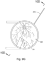
- FIGS. 9G and 10C-10D show cannula (20) as it is guided between sclera (304) and choroid (306) to the delivery site for the therapeutic agent.
- the delivery site corresponds to a generally posterior region of eye (301) adjacent to an area of geographic atrophy of retina (308).
- the delivery site of the present example is superior to the macula, in the potential space between the neurosensory retina and the retinal pigment epithelium layer.
- FIG. 9G shows eye (301) under direct visualization through a microscope directed through the pupil of eye (301), with illumination provided through fiber (315) and port (314).
- cannula (20) is at least partially visible through a retina (308) and choroid (306) of eye (301).
- an operator may track cannula (20) as it is advanced through eye (301) from the position shown in FIG. 10C to the position shown in 10D. Such tracking may be enhanced in versions where an optical fiber (34) is used to emit visible light through the distal end of cannula (20).
- needle (30) of instrument (10) may advance needle (30) of instrument (10) as described above with respect to FIGS. 3-4 .
- needle (30) is advanced relative to cannula (20) such that needle (30) pierces through choroid (306) without penetrating retina (308).
- needle (30) may appear under direct visualization as "tenting" the surface of choroid (306), as can be seen in FIG. 9H .
- needle (30) may deform choroid (306) by pushing upwardly on choroid, providing an appearance similar to a tent pole deforming the roof of a tent.
- a visual phenomenon may be used by an operator to identify whether choroid (306) is about to be pierced and the location of any eventual piercing.
- the particular amount of needle (30) advancement sufficient to initiate "tenting" and subsequent piercing of choroid (306) may be of any suitable amount as may be determined by a number of factors such as, but not limited to, general patient anatomy, local patient anatomy, operator preference, and/or other factors.
- a merely exemplary range of needle (30) advancement may be between approximately 0.25 mm and approximately 10 mm; or more particularly between approximately 2 mm and approximately 6 mm.
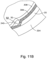
- leading bleb (340) may be desirable for two reasons. First, as shown in FIGS. 9I , 10F , and 11B , leading bleb (340) may provide a further visual indicator to an operator to indicate when needle (30) is properly positioned at the delivery site.
- leading bleb (340) may provide a barrier between needle (30) and retina (308) once needle (30) has penetrated choroid (306). Such a barrier may push the retinal wall outwardly (as is best seen in FIGS. 10F and 11B ), thereby minimizing the risk of retinal perforation as needle (30) is advanced to the delivery site.
- a foot pedal is actuated in order to drive leading bleb (340) out from needle (30).
- other suitable features that may be used to drive leading bleb (340) out from needle (30) will be apparent to those of ordinary skill in the art in view of the teachings herein.
- a therapeutic agent (341) may be infused by actuating a syringe or other fluid delivery device as described above with respect to instrument (10).
- the particular therapeutic agent (341) delivered may be any suitable therapeutic agent configured to treat an ocular condition.
- suitable therapeutic agents may include, but are not necessarily limited to, drugs having smaller or large molecules, therapeutic cell solutions, certain gene therapy solutions, and/or any other suitable therapeutic agent as will be apparent to those of ordinary skill in the art in view of the teachings herein.
- the therapeutic agent (341) may be provided in accordance with at least some of the teachings of U.S. Patent No. 7,413,734, entitled “Treatment of Retinitis Pigmentosa with Human Umbilical Cord Cells,” issued August 19, 2008 .
- the amount of therapeutic agent (341) that is ultimately delivered to the delivery site is approximately 50 ⁇ L, although any other suitable amount may be delivered.
- a foot pedal is actuated in order to drive agent (341) out from needle (30).
- other suitable features that may be used to drive agent (341) out from needle (30) will be apparent to those of ordinary skill in the art in view of the teachings herein. Delivery of therapeutic agent may be visualized by an expansion of the pocket of fluid as can be seen in FIGS. 9J , 10G , and 11C . As shown, therapeutic agent (341) essentially mixes with the fluid of leading bleb (340) as therapeutic agent (341) is injected into the surprachoroidal space.
- needle (20) may be retracted by sliding actuation assembly (60) proximally relative to body (40); and cannula (30) may then be withdrawn from eye (301). It should be understood that because of the size of needle (20), the site where needle (20) penetrated through choroid (306) is self sealing, such that no further steps need be taken to seal the delivery site through choroid (306). Suture loop assembly (330) and chandelier (314) may be removed, and incision (316) in the sclera (304) may be closed using any suitable conventional techniques.
- the therapeutic agent (341) that is delivered by needle (20) may comprise cells that are derived from postpartum umbilicus and placenta.
- the therapeutic agent (341) may be provided in accordance with at least some of the teachings of U.S. Patent No. 7,413,734, entitled “Treatment of Retinitis Pigmentosa with Human Umbilical Cord Cells," issued August 19, 2008 .
- needle (20) may be used to deliver any other suitable substance or substances, in addition to or in lieu of those described in U.S. Patent No. 7,413,734 and/or elsewhere herein.
- therapeutic agent (341) may comprise various kinds of drugs including but not limited to small molecules, large molecules, cells, and/or gene therapies. It should also be understood that macular degeneration is just one merely illustrative example of a condition that may be treated through the procedure described herein. Other biological conditions that may be addressed using the instruments and procedures described herein will be apparent to those of ordinary skill in the art.
- the instruments described herein may be desirable to vary certain components or features of the instruments described herein in order to vary the technique for delivering therapeutic agent to the subretinal space of an eye. In some examples, it may further be desirable to vary certain steps or features of the surgical procedures described herein. For instance, it may be desirable to vary the surgical procedures described herein by utilizing instruments similar to instruments (10, 2010) with features configured to limit the need to cut the eye using a scalpel or other cutting instrument as described above. Instruments having the above referenced variations may be desirable for different surgical procedures, or surgical procedures similar to the procedure discussed above, to engage tissue structures having varying physical properties. While certain examples of variations are described herein, it should be understood that the instruments described herein may include any other alternative features as will be apparent to those of ordinary skill in the art in view of the teachings herein.
- FIG. 12 shows an exemplary instrument (400) that is configured for use in a procedure for the subretinal administration of a therapeutic agent to an eye of a patient.
- Instrument (400) comprises a needle (420), a body (440), and a micro-catheter (460). Needle (420) extends distally from body (440). Needle (420) is generally configured to support micro-catheter (460), as will be described in more detail below. Also as will be described in more detail below, needle (420) has sufficient column strength to permit piercing and advancement of needle (420) through the sclera and the choroid to the subretinal space of a patient's eye without buckling.
- Needle (420) has a sharp distal end (422) and defines an internal lumen (not shown) extending longitudinally through needle (420). As will be described in more detail below, the lumen of needle (420) is configured to slidably receive micro-catheter (460).
- Sharp distal end (422) is configured to provide for piercing and penetration of the sclera and choroid layers to enable needle (420) to be advanced through such layers to the subretinal space while not inflicting other incidental trauma to the sclera or choroid layers.
- Distal end (422) of the present example has a lancet configuration.
- distal end (422) has a tri-bevel configuration or any other configuration as described in U.S. Pat. App. No. 14/619,256, entitled “Method and Apparatus for Suprachoroidal Administration of Therapeutic Agent," filed February 11, 2015 . Still other suitable forms that distal end (422) may take will be apparent to those of ordinary skill in the art in view of the teachings herein.
- Needle (420) of the present example comprises a stainless steel hypodermic needle that is sized to receive micro-catheter (460) while being small enough to minimize incidental trauma as needle (420) penetrates tissue structures of the patient's eye, as will be described in greater detail below.
- needle (420) may be 23 gauge, although other suitable sizes may be used.
- Body (440) is generally T-shaped with an outwardly projecting fluid port (442).
- the particular shape of body (440) that is shown is configured to be grasped by an operator.
- body (440) may be mounted on a support device or arm for ease of positioning instrument (400), as described in U.S. Pat. App. No. 14/619,256, entitled “Method and Apparatus for Suprachoroidal Administration of Therapeutic Agent,” filed February 11, 2015 .
- Fluid port (442) provides fluid access to an interior of body (440).
- a fluid supply line (444) is coupled with fluid port (442) and configured to provide fluid to the interior of body (440).
- needle (420) is in fluid communication with the interior of body (440) such that fluid (e.g., Healon ® OVD manufactured by Abbott Medical Optics) provided via fluid supply line (444) is communicated to the distal end of needle (420) via the lumen formed within needle (420).
- fluid e.g., Healon ® OVD manufactured by Abbott Medical Optics
- a proximal portion of body (440) includes a ferrule (446).
- Ferrule (446) provides access to the interior of body (440).
- Ferrule (446) is configured to slidably receive micro-catheter (460) such that micro-catheter (460) may be passed through ferrule (446) into the interior of body (440).
- a portion of micro-catheter (460) is exposed relative to ferrule (446) such that an operator may engage and manually translate micro-catheter (460).
- Ferrule (446) includes a sealing element (e.g., a wiper seal or an o-ring, etc.) (not shown), which permits translation of micro-catheter (460) within and relative to ferrule (446) while preventing inadvertent leakage of fluid from the interior of body (440).
- Needle (420) is configured to slidably receive micro-catheter (460).
- Micro-catheter (460) is thus configured to pass through ferrule (446), through the interior of body (440), and into the lumen of needle (420).
- Needle (420) of the present example is sized such that even with micro-catheter (460) positioned within the lumen of needle (420), fluid may nevertheless pass through needle (420) about micro-catheter (460).
- Micro-catheter (460) may be manually translated within and relative to needle (420). For instance, micro-catheter (460) may be translated distally relative to needle (420) to a point where micro-catheter (460) extends distally from the distal end of needle (420).
- micro-catheter (460) may be advanced distally from the distal end of needle (420) between the choroid and the retina of a patient's eye to a position at the back of the patient's eye. This advancement of micro-catheter (460) is performed by an operator manually translating micro-catheter (460). Micro-catheter (460) is flexible enough to conform to specific structures and contours of the patient's eye, yet micro-catheter (460) has sufficient column strength to permit advancement of micro-catheter (460) between the choroid and the retina of a patient's eye without buckling.
- Needle (420) is generally configured to direct micro-catheter (460) along an exit axis that is angularly oriented obliquely relative to a longitudinal axis of needle (420). It should be understood that such an angle may be desirable to deflect micro-catheter (460) in a direction to ensure that micro-catheter (460) continues beneath the retina (308) through the subretinal space (as opposed to penetrating the retina (308)) and to prevent penetration of micro-catheter (460) into the retina (308).
- micro-catheter (460) defines an internal lumen (not shown). With micro-catheter (460) positioned at the back of the patient's eye, the lumen of micro-catheter (460) is configured to permit the flow of fluid (e.g., a therapeutic agent) through micro-catheter (460) to the distal end of micro-catheter (460) so as to deliver the fluid to the back of the patient's eye. Once the fluid has been delivered to the back of the patient's eye, micro-catheter (460) may be drawn proximally back into the distal end of needle (420). This proximal translation of micro-catheter (460) is performed by an operator manually translating micro-catheter (460).
- fluid e.g., a therapeutic agent
- micro-catheter (460) includes an illuminating element (462) that is configured to assist in tracking or positioning of micro-catheter (460) within the patient's eye.
- FIGS. 13-20B show an exemplary alternative instrument (500) that is similar to instrument (400) described above. While certain features and operabilities of instrument (500) are described below, it should be understood that, in addition to or in lieu of the following, instrument (500) may be configured and/or operable in accordance with any of the teachings of U.S. Pat. App. No. 14/619,256, entitled “Method and Apparatus for Suprachoroidal Administration of Therapeutic Agent," filed February 11, 2015 . Like with instrument (400), instrument (500) of the present example is generally usable in the procedure described herein to deliver a therapeutic fluid subretinally to an eye of a patient.
- instrument (500) may be readily used in place of instrument (400) to perform the medical procedures described herein.
- instrument (500) of this example comprises a needle (520), body (540), and a micro-catheter (560).
- Needle (520) comprises a stainless steel hypodermic needle that is is substantially the same as needle (420) described above.
- needle (520) and micro-catheter (560) are substantially identical to needle (420) and micro-catheter (460) described above.
- Needle (520) extends distally from body (540). Needle (520) is generally configured to support micro-catheter (560), as will be described in more detail below. Also as will be described in more detail below, needle (520) has sufficient column strength to permit piercing and advancement of needle (520) through the sclera and the choroid to the subretinal space of a patient's eye without buckling. Needle (520) includes a generally straight proximal portion (520A) and a bent distal portion (520B). Bent distal portion (520B) of the present example is bent to improve the ergonomics of instrument (500), enabling the operator to insert needle (520) at an appropriate angle relative to the eye without having to hold instrument at an awkward angle relative to the operator.
- micro-catheter (560) may be desirable to deflect micro-catheter (560) in a direction to ensure that micro-catheter (560) continues beneath the retina (308) through the subretinal space and to prevent penetration of micro-catheter (560) through the retina (308).
- needle (520) has a sharp distal end (522) and defines an internal lumen (524) extending through needle (520).
- lumen (524) of needle (520) is configured to slidably receive micro-catheter (560).
- Sharp distal end (522) is configured to provide for piercing of the sclera and choroid layers to enable needle (520) to be advanced through such layers to the subretinal space while not inflicting other incidental trauma to the sclera or choroid layers.
- Distal end (522) of the present example has a lancet configuration.
- distal end (522) has a tri-bevel configuration or any other configuration as described in U.S. Pat. App. No. 14/619,256, entitled “Method and Apparatus for Suprachoroidal Administration of Therapeutic Agent," filed February 11, 2015 . Still other suitable forms that distal end (522) may take will be apparent to those of ordinary skill in the art in view of the teachings herein.
- Needle (520) of the present example comprises a stainless steel hypodermic needle that is sized to receive micro-catheter (560) while being small enough to minimize incidental trauma as needle (520) penetrates tissue structures of the patient's eye, as will be described in greater detail below.
- needle (520) may be 23 gauge, although other suitable sizes may be used.
- Body (540) is generally elongate shaped and includes an outwardly projecting fluid port (542) extending from a distal portion of body (540).
- the particular shape of body (540) that is shown is configured to be grasped by an operator.
- body (540) may be mounted on a support device or arm for ease of positioning instrument (500), as described in U.S. Pat. App. No. 14/619,256, entitled “Method and Apparatus for Suprachoroidal Administration of Therapeutic Agent," filed February 11, 2015 .
- fluid port (542) provides fluid access to an interior (541) of body (540).
- a fluid supply line may be coupled with fluid port (542) and configured to provide fluid to the interior (541) of body (540).
- needle (520) is in fluid communication with the interior (541) of body (540) such that fluid (e.g., Healon ® OVD manufactured by Abbott Medical Optics) provided via the fluid supply line is communicated to the distal end of needle (520) via lumen (524) formed within needle (520).
- fluid e.g., Healon ® OVD manufactured by Abbott Medical Optics
- instrument (500) includes a gear assembly (580) that is configured to drive translation of micro-catheter (560) relative to needle (520).
- Body (540) includes a sled (550) that is slidably disposed within a cylindrical bore (546) formed in a proximal portion of body (540).
- Sled (550) is operable to translate longitudinally within cylindrical bore (546) between a proximal longitudinal position ( FIG. 20A ) and a distal longitudinal position ( FIG. 20B ).
- Body (540) includes a pin (548) positioned within an elongate slot (552) formed in a bottom surface of sled (550) ( FIG. 19 ).
- Pin (548) is operable to limit longitudinal translation of sled (550) based upon the longitudinal length of slot (552).
- Gear assembly (580) includes a pair of rotatable members (582, 584).
- Rotatable member (582) includes a pair of gears (586, 588) positioned at opposite ends of rotatable member (582).
- Rotatable member (582) is partially exposed relative to body (540) such that an operator may engage rotatable member (582) using his or her fingers or thumb to thereby cause rotation of rotatable member (582).
- Rotatable member (584) includes an elongate gear (583), which extends substantially the length of rotatable member (584).
- Rotatable member (582) is rotatable about an axis that is perpendicular to the longitudinal axis of body (540).
- sled (550) includes a plurality of gear teeth (558) extending longitudinally along a length of sled (550). Teeth (558) of sled (550) engage teeth of gear (583) of rotatable member (584) in a rack and pinion relationship. Thus, rotation of rotatable member (584) causes longitudinal translation of sled (550) between the proximal longitudinal position ( FIG. 20A ) and the distal longitudinal position ( FIG. 20B ).
- rotation of rotatable member (582) in a first direction will cause distal longitudinal translation of sled (550) relative to body (540) and that rotation of rotatable member (582) in a second direction will cause proximal longitudinal translation of sled (550) relative to body (540).
- micro-catheter (560) is coupled with sled (550) such that translation of sled (550) causes concurrent translation of micro-catheter (560).
- Micro-catheter (560) extends distally through a bore (554) formed in sled (550) and extends distally therefrom. It should therefore be appreciated that rotation of rotatable member (582) in a first direction will cause distal longitudinal translation of micro-catheter (560) relative to needle (520) and that rotation of rotatable member (582) in a second direction will cause proximal longitudinal translation of micro-catheter (560) relative to needle (520).
- Micro-catheter (560) passes through a bore (549) formed in body (540), through the interior (541) of body (540), into lumen (524) of needle (520).
- Bore (549) of body (540) may include a sealing element (e.g., a wiper seal, an o-ring, etc.) (not shown) that permits translation of micro-catheter (560) within and relative to bore (549) while preventing inadvertent leakage of fluid from the interior (541) of body (540).
- Needle (520) of the present example is sized such that even with micro-catheter (560) positioned within the lumen of needle (520), fluid may nevertheless pass through needle (520) about micro-catheter (560).
- Micro-catheter (560) may be translated within and relative to needle (520) via translation of sled (550). For instance, micro-catheter (560) may be translated distally relative to needle (520) to a point where micro-catheter (560) extends distally from the distal end of needle (520).
- micro-catheter (560) may be advanced distally from the distal end of needle (520) between the choroid and the retina of a patient's eye to a position at the back of the patient's eye. This advancement of micro-catheter (560) is performed by rotation of rotatable member (582) in a first direction shown in FIGS. 20A and 20B .
- Micro-catheter (560) is flexible enough to conform to specific structures and contours of the patient's eye, yet micro-catheter (560) has sufficient column strength to permit advancement of micro-catheter (560) between the choroid and the retina of a patient's eye without buckling.
- Needle (520) is generally configured to direct micro-catheter (560) along an exit axis that is angularly oriented obliquely relative to a longitudinal axis of needle (520). It should be understood that such an angle may be desirable to deflect micro-catheter (560) in a direction to ensure that micro-catheter (560) continues beneath the retina (308) through the subretinal space and to prevent penetration of micro-catheter (560) through the retina (308).
- micro-catheter (560) defines an internal lumen. With micro-catheter (560) positioned at the back of the patient's eye, the lumen of micro-catheter (560) is configured to permit the flow of fluid (e.g., a therapeutic agent) through micro-catheter (560) to the distal end of micro-catheter (560) so as to deliver the fluid to the back of the patient's eye. Once the fluid has been delivered to the back of the patient's eye, micro-catheter (560) may be drawn proximally back into the distal end of needle (520). This proximal translation of micro-catheter (560) is performed by rotation of rotatable member (582) in a second direction. Also as will be described in more detail below, micro-catheter (560) may include an illuminating element that is configured to assist in tracking or positioning of micro-catheter (560) within the patient's eye.
- fluid e.g., a therapeutic agent
- FIGS. 21-27B show an exemplary alternative instrument (600) that is similar to instruments (400, 500) described above. While certain features and operabilities of instrument (600) are described below, it should be understood that, in addition to or in lieu of the following, instrument (600) may be configured and/or operable in accordance with any of the teachings of U.S. Pat. App. No. 14/619,256, entitled “Method and Apparatus for Suprachoroidal Administration of Therapeutic Agent," filed February 11, 2015 . Like with instruments (400, 500), instrument (600) of the present example is generally usable in the procedure described herein to deliver a therapeutic fluid subretinally to an eye of a patient.
- instrument (600) may be readily used in place of instruments (400, 500) to perform the medical procedures described herein.
- instrument (600) of this example comprises a needle (620), body (640), and a micro-catheter (660).
- Needle (620) comprises a stainless steel hypodermic needle that is substantially the same as needles (420, 520) described above.
- needle (620) and micro-catheter (660) are substantially identical to needles (420, 520) and micro-catheters (460, 560) described above.
- Needle (620) extends distally from body (640). Needle (620) is generally configured to support micro-catheter (660), as will be described in more detail below. Also as will be described in more detail below, needle (620) has sufficient column strength to permit piercing and advancement of needle (620) through the sclera and the choroid to the subretinal space of a patient's eye without buckling. Needle (620) has a sharp distal end (622) and defines an internal lumen (624) extending through needle (620). As will be described in more detail below, lumen (624) of needle (620) is configured to slidably receive micro-catheter (660).
- Sharp distal end (622) is configured to provide for piercing of the sclera and choroid layers to enable needle (620) to be advanced through such layers to the subretinal space while not inflicting other incidental trauma to the sclera or choroid layers.
- Distal end (622) of the present example has a lancet configuration.
- distal end (622) has a tri-bevel configuration or any other configuration as described in U.S. Pat. App. No. 14/619,256, entitled “Method and Apparatus for Suprachoroidal Administration of Therapeutic Agent," filed February 11, 2015 . Still other suitable forms that distal end (622) may take will be apparent to those of ordinary skill in the art in view of the teachings herein.
- Needle (620) of the present example comprises a stainless steel hypodermic needle that is sized to receive micro-catheter (660) while being small enough to minimize incidental trauma as needle (620) penetrates tissue structures of the patient's eye, as will be described in greater detail below.
- needle (620) may be 23 gauge, although other suitable sizes may be used.
- Body (640) is generally elongate shaped and includes an outwardly extending fluid supply line (642).
- the particular shape of body (640) that is shown is configured to be grasped by an operator.
- body (640) may be mounted on a support device or arm for ease of positioning instrument (600), as described in U.S. Pat. App. No. 14/619,256, entitled “Method and Apparatus for Suprachoroidal Administration of Therapeutic Agent," filed February 11, 2015 .
- instrument (600) includes a dumbbell-shaped rotatable member (652) that is operable to control a Tuohy-Borst valve; and a plunger assembly (690) that is configured to cause translation of micro-catheter (660).
- rotatable member (652) is rotatably disposed within a similarly shaped bore (646) formed in body (640). Rotatable member (652) is operable to rotate within bore (646).
- a proximal portion of rotatable member (652) is exposed relative to body (640) via an opening (644) formed in a top surface of body (640) such that an operator may engage rotatable member (652) using his or her fingers or thumb to thereby cause rotation of rotatable member (652).
- a distal portion (654) of rotatable member (652) includes interior threading (655) formed in a cylindrical bore (656) of distal portion (654).
- a proximal end of needle (620) is coupled with a conical hub (623), which includes an outwardly extending flange (651).
- Flange (651) is coupled with threading (655) to form a luer fitting, thereby fixedly securing needle (620) relative to rotatable member (652) in a fluid tight manner.
- needle (620) may be secured to rotatable member (652) in any other suitable fashion.
- a tube (659) extends through cylindrical bore (656) of rotatable member (650) ante terminates in a ferrule member (645), which includes an internal seal (657) in the form of an o-ring.
- Seal (657) permits translation of micro-catheter (660) within and relative to tube (659) while selectively preventing inadvertent leakage of fluid from the interior of tube (659).
- rotatable member (652), ferrule member (645), and seal (657) cooperate to form a Tuohy-Borst valve in a manner as will be apparent to those of ordinary skill in the art in view of the teachings herein.
- rotatable member (652) is operable to cinch down on the assembly of tube (659), ferrule member (645), and seal (657) to thereby prevent fluid communication to/from the interior of tube (659) via the proximal end of the assembly of tube (659), ferrule member (645), and seal (657).
- Rotatable member (652) is rotatable relative to body (640). Since needle (620) is fixedly secured to rotatable member (652), needle (620) also thus rotatable relative to body (640). In other words, an operator may rotate rotatable member (652) relative to body (640) to thereby rotate needle (620) relative to body (640). Such rotation of needle may be desirable in order to position distal end (622) at a desired angular position about the longitudinal axis of needle (620) relative to the eye of the patient.
- an operator may wish to rotate needle (620) relative to body (640) while driving needle (620) through the sclera (304), as such rotation of needle (620) may reduce the longitudinal force required to penetrate the sclera (304) with needle (620).
- Fluid supply line (642) provides fluid access to cylindrical bore (656) of rotatable member (652).
- needle (620) is in fluid communication with cylindrical bore (656) of rotatable member (652) via hub (623) such that fluid (e.g., Healon ® OVD manufactured by Abbott Medical Optics) provided via fluid supply line (642) is communicated to the distal end of needle (620) via lumen (624) formed within needle (620).
- fluid e.g., Healon ® OVD manufactured by Abbott Medical Optics
- Plunger assembly (690) includes a plunger (692) that is slidably disposed within a proximal portion of body (640). Plunger (692) is operable to translate longitudinally relative to body (640) between a proximal longitudinal position ( FIG. 26A ) and a distal longitudinal position ( FIG. 26B ). Plunger (692) includes a pin (694) positioned within an elongate slot (646) formed in a top surface of body (640). Pin (694) is operable to limit longitudinal translation of plunger (692) based upon the longitudinal length of slot (646). As best seen in FIG.
- plunger (692) includes a pair of elongate projections (696) that are disposed on opposite sides of and extending from an exterior surface of plunger (692). Projections (696) are slidably disposed within a pair of mating elongate slots (648) that are formed in an interior surface of body (640) so as to prevent rotation of plunger (692) while permitting translation of plunger (692) relative to body (640).
- micro-catheter (660) is coupled with plunger (692) such that translation of plunger (692) relative to body (640) causes concurrent translation of micro-catheter (660) relative to body (640).
- Micro-catheter (660) extends distally through a bore (698) formed in plunger (692) and extends distally therefrom. Micro-catheter (660) then passes through tube (659) and into lumen (624) of needle (620). Seal (657) permits translation of micro-catheter (660) within and relative to tube (659) while preventing inadvertent leakage of fluid from the interior of tube (659).
- Needle (620) of the present example is sized such that even with micro-catheter (660) positioned within lumen (624) of needle (620), fluid may nevertheless pass through needle (620) about micro-catheter (660).
- Micro-catheter (660) may be translated within and relative to needle (620) via translation of plunger (692). For instance, micro-catheter (660) may be translated distally relative to needle (620) to a point where micro-catheter (660) extends distally from the distal end of needle (620).
- micro-catheter (660) may be advanced distally from the distal end (622) of needle (620) between the choroid (306) and the retina (308) of a patient's eye to a position at the back of the patient's eye.
- the insertion of needle (620) is performed by advancing the entire instrument (600) distally; while the advancement of micro-catheter (660) is performed by distal translation of plunger (692) relative to body (640).
- Micro-catheter (660) is flexible enough to conform to specific structures and contours of the patient's eye, yet micro-catheter (660) has sufficient column strength to permit advancement of micro-catheter (660) between the choroid and the retina of a patient's eye without buckling.
- Needle (620) is generally configured to direct micro-catheter (660) along an exit axis that is angularly oriented obliquely relative to a longitudinal axis of needle (620).
- micro-catheter (660) may be desirable to deflect micro-catheter (660) in a direction to ensure that micro-catheter (660) continues beneath the retina (308) through the subretinal space (as opposed to penetrating the retina (308)) and to minimize penetration of micro-catheter (660) into the retina (308).
- micro-catheter (660) defines an internal lumen. With micro-catheter (660) positioned at the back of the patient's eye, the lumen of micro-catheter (660) is configured to permit the flow of fluid (e.g., a therapeutic agent) through micro-catheter (660) to the distal end of micro-catheter (660) so as to deliver the fluid to the back of the patient's eye. Once the fluid has been delivered to the back of the patient's eye, micro-catheter (660) may be drawn proximally back into the distal end of needle (620). This proximal translation of micro-catheter (660) is performed by proximal translation of plunger (692).
- fluid e.g., a therapeutic agent
- micro-catheter (660) may include an illuminating element that is configured to assist in tracking or positioning of micro-catheter (660) within the patient's eye.
- guidance devices that are operable to assist an operator in properly aligning needle (420, 520, 620) of instrument (400, 500, 600) relative to a patient's eye (301).
- such guidance devices may be configured to guide needle (420, 520, 620) into a patient's eye (301) along a path that is tangential to the retina (308), such that upon penetration of the patient's eye (301), needle (420, 520, 620) advances along a path such that a distal end of needle (420, 520, 620) advances through the sclera (304) and the choroid (306) to the subretinal space of the eye (301).
- Such guidance devices may come in different sizes and dimensions and may provided for different paths of advancement to accommodate the anatomical differences in each patient's eyes (301). While certain examples of variations are described herein, it should be understood that the instruments described herein may include any other alternative features as will be apparent to those of ordinary skill in the art in view of the teachings herein.
- FIGS. 28-39 show an exemplary guidance device (700).
- Guidance device (700) comprises an annular base (710), a bottom surface (712) of which is configured to complement the contour of the limbic region of a patient's eye (301).
- Annular base (710) includes a plurality of suture loops (714) such that guidance device (700) may be secured to a patient's eye (301) via sutures (715) passed through suture loops (714) as shown in FIG. 39 .
- guidance device (700) may be secured to a patient's eye (301) via adhesives, suction, micro-barbs, textured surfaces, or by contact pressure and stabilization by an operator.
- Annular base (710) further includes a guidance anchor (716), a bottom surface (717) of which is also configured to complement the contour of a patient's eye (301).
- guidance anchor (716) With guidance device (700) secured to a patient's eye (301), guidance anchor (716) is shaped to extend along a side region of a patient's eye (301) as best seen in FIGS. 39 -40C.
- Guidance anchor (716) includes a pair of suture loops (718) such that guidance anchor (716) may be secured to a patient's eye (301) via sutures (715) that are passed through suture loops (718) as shown in FIG. 39 . Additionally or alternatively, guidance anchor (716) may be secured to a patient's eye (301) via adhesives, suction, micro-barbs, textured surfaces, or by contact pressure and stabilization by an operator.
- guidance anchor (716) includes a plurality of through bores (740A, 740B, 740C, 740D), which extend completely through guidance anchor (716).
- Through bores (740A, 740B, 740C, 740D) are configured to receive needle (420, 520, 620) of instrument (400, 500, 600) so as to guide needle (420, 520, 620) into contact with a patient's eye (301) at a predetermined angle.
- each through bore (740A, 740B, 740C, 740D) includes a filleted opening (742) formed in a top surface (719) of guidance anchor (716).
- Filleted openings (742) are configured to assist an operator in guiding needles (420, 520, 620) into through bores (740A, 740B, 740C, 740D).
- each through bore (740A, 740B, 740C, 740D) defines a unique guidance pathway based on a position and angle of entry provided by each through bore (740A, 740B, 740C, 740D).
- each through bore (740A, 740B, 740C, 740D) will direct needle (420, 520, 620) into contact with a patient's eye (301) along a unique path via contact between interior surfaces of through bores (740A, 740B, 740C, 740D) and an exterior surface of needle (420, 520, 620).
- An operator may determine which unique path is most appropriate based on the individual characteristics (contour, curvature, thickness, toughness, etc.) of each patient's eyes (301).
- an operator may determine the most appropriate path for directing needle (420, 520, 620) through the sclera (304) and the choroid (306) to the subretinal space of a patient's eye (301).
- Guidance device (700) further comprises a frusto-conical projection (720) extending upwardly from annular base (710).
- frusto-conical projection (720) is configured to receive a viewing lens (750) that is operable to provide for viewing of the interior of a patient's eye (301) through the pupil of the eye (301) via an opening (722) formed through frusto-conical projection (720) and annular base (710) as best seen in FIG. 33 .
- a support frame (730) extends upwardly from frusto-conical projection (720).
- support frame (730) is configured to selectively secure viewing lens (750) to guidance device (700) and to further provide support and stability to viewing lens (750) during use.
- Support frame (730) includes a semi-circular support member (732).
- Support member (732) is resiliently biased to the shape best seen in FIGS. 28 and 29 .
- Support member (732) includes a pair of curved flanges (734), which provide support member (732) with a flared opening operable to receive viewing lens (750).
- viewing lens (750) may be secured within guidance device (700).
- Viewing lens (750) may be, for instance, one of several ophthalmic lenses manufactured by Volk ® or any other appropriate type of viewing lens.
- viewing lens (750) is secured within guidance device (700) via engagement with frusto-conical projection (720) and support member (732) of support frame (730).
- viewing lens (750) may engage and be secured within frusto-conical projection (720) via interference or snap fit.
- viewing lens (750) may be secured within frusto-conical projection (720) via adhesives or by any other appropriate manner.
- viewing lens (750) may be stabilized by an operator.
- viewing lens (750) As viewing lens (750) is driven into contact with frusto-conical projection (720), contact between viewing lens (750) and flanges (734) of support member (732) causes support member (732) to open outwardly such that viewing lens (750) may be received within support member (732). As viewing lens (750) is positioned further within support member (732) to the position shown in FIGS. 37 and 38 , support member (732) returns to its original shape to thereby selectively secure viewing lens (750) within support member (750).
- viewing lens (750) secured within guidance device (700), and with guidance device (700) secured to a patient's eye (301), an operator may use viewing lens (750) to view the interior of a patient's eye (301) through the pupil of the eye via opening (722) formed through frusto-conical projection (720) and annular base (710).
- viewing lens (750) may assist an operator in tracking or position of needle (420, 520, 620) and/or micro-catheter (460, 560, 660) within a patient's eye (301). It should be appreciated that before or during a surgical procedure, viewing lens (750) may be removed and perhaps replaced by other viewing lenses depending upon the need of an operator.
- support frame (730) may be omitted from guidance device (700).
- viewing lens (750) may be secured within guidance device (700) via engagement with frusto-conical projection (720) as shown in FIGS. 43 and 44 .
- viewing lens (750) may engage and be secured within frusto-conical projection (720) via interference or friction fit.
- viewing lens (750) may be secured within frusto-conical projection (720) via adhesives or by any other appropriate manner.
- viewing lens (750) may be stabilized by an operator.
- frusto-conical projection (720) may be omitted from guidance device (700).
- viewing lens (750) may be secured to guidance device (700) via engagement with annular base (710) as shown in FIGS. 48 and 49 .
- viewing lens (750) may engage and be secured to annular base (710) via interference or friction fit.
- viewing lens (750) may be secured within annular base (710) via adhesives or by any other appropriate manner.
- viewing lens (750) may be stabilized by an operator.
- guidance anchor (716) may include a guidance tube (760) that extends upwardly from guidance anchor (716).
- a lumen (762) that extends along the length of guidance tube (760) serves as an extension for one or more through bores (740A, 740B, 740C, 740D).
- This extended length of one or more through bores (740A, 740B, 740C, 740D) provides for additional contact between the interior surfaces of through bores (740A, 740B, 740C, 740D) and the exterior surface of needle (420, 520, 620).
- This increased contact provides for more accurate guidance of needle (420, 520, 620) as needle (420, 520, 620) is advanced through the sclera (304) and the choroid (306) to the subretinal space of a patient's eye (301).
- FIGS. 52A-53D show an exemplary procedure for subretinal delivery of therapeutic agent using instrument (400) described above. It should be understood however, that instruments (500, 600) may be readily used in addition to or in lieu of instrument (400) in the procedure described below. Instruments (10, 2010) may also be modified to perform the procedure described below. It should also be understood that instruments (10, 2010) may be readily modified to include at least some of the above described features of instruments (400, 500, 600), even if instruments (10, 2010) are only to be used in a procedure for subretinal administration of a therapeutic agent from a suprachoroidal approach as described above with reference to FIGS. 9A-11C . Other suitable ways in which the teachings herein may be interchanged and combined will be apparent to those of ordinary skill in the art.
- the method described herein may be employed to treat macular degeneration and/or other ocular conditions.
- the procedure described herein is discussed in the context of the treatment of age-related macular degeneration, it should be understood that no such limitation is intended or implied.
- the same techniques described herein may be used to treat retinitis pigmentosa, diabetic retinopathy, and/or other ocular conditions.
- the procedure described herein may be used to treat either dry or wet age-related macular degeneration.
- the procedure begins by an operator immobilizing tissue surrounding a patient's eye (301) (e.g., the eyelids) using a speculum (312), and/or any other instrument suitable for immobilization as can be seen in FIG. 9A .
- a speculum (312) e.g., the eyelids
- viewing lens (750) is secured within guidance device (700) as described above.
- Guidance device (700) and viewing lens (750) are then positioned on the limbic region of the patient's eye (301) and secured thereto via suture loops (714) of annular base (710) and sutures (715).
- the operator secures guidance device (700) to the patient's eye (301) with sutures (715) first; then secures lens (750) to guidance device (700) after guidance device (700) has been secured to the patient's eye (301).
- needle (420) is inserted into the through bore (740A, 740B, 740C, 740D) as shown in FIG. 52A .
- needle (420) is pierces the sclera (304) and advances needle (420) relative to guidance device (700) such that needle (420) pierces through choroid (306) without penetrating retina (308).
- needle (420) may appear under direct visualization as "tenting" the surface of choroid (306).
- needle (420) may deform the choroid (306) by pushing upwardly on the choroid (306), providing an appearance similar to a tent pole deforming the roof of a tent as described above. Such a visual phenomenon may be used by an operator to identify whether the choroid (306) is about to be pierced and the location of any eventual piercing.
- the particular amount of needle (420) advancement sufficient to initiate "tenting" and subsequent piercing of the choroid (306) may be of any suitable amount as may be determined by a number of factors such as, but not limited to, general patient anatomy, local patient anatomy, operator preference, and/or other factors. As described above, a merely exemplary range of needle (420) advancement may be between approximately 0.25 mm and approximately 10 mm; or more particularly between approximately 2 mm and approximately 6 mm.
- needle (400, 500, 600) may include one or more markers on the exterior surfaces of needle (400, 500, 600) to indicate various depths of insertion. While merely optional, such markers may be desirable to aid an operator in identifying the proper depth of insertion as needle (400, 500, 600) is guided into the patient's eye (301). For instance, the operator may visually observe the position of such markers in relation to guidance anchor (716) and/or in relation to guidance tube (760) as an indication of the depth to which needle (400, 500, 600) is inserted into the eye (301). By way of example only, one such marker may correspond to an approximately 6 mm depth of insertion of needle (400, 500, 600).
- leading bleb (770) may be desirable for two reasons. First, leading bleb (770) may provide a further visual indicator to an operator to indicate when needle (420) is properly positioned. Second, leading bleb (770) may provide a barrier between needle (420) and retina (308) once needle (420) has penetrated choroid (306).
- a barrier may push the retinal wall outwardly (as is best seen in FIG. 52C ), thereby minimizing the risk of retinal perforation as micro-catheter (460) is advanced to the delivery site.
- a foot pedal is actuated in order to drive leading bleb (770) out from needle (420).
- other suitable features that may be used to drive leading bleb (770) out from needle (420) will be apparent to those of ordinary skill in the art in view of the teachings herein.
- FIGS. 53A-53D show micro-catheter (460) as it is guided between choroid (306) and retina (308) to the delivery site for the therapeutic agent (774).
- the delivery site corresponds to a generally posterior region of eye (301) adjacent to an area of geographic atrophy of retina (308).
- the delivery site of the present example is superior to the macula, in the potential space between the neurosensory retina and the retinal pigment epithelium layer.
- micro-catheter (460) is advanced distally from the distal end of needle (420) into the space provided by lead bleb (770).
- Micro-catheter (460) is at least partially visible through retina (308) of eye (301).
- micro-catheter (460) may include an illuminating element (462), which may be seen via viewing lens (750). Micro-catheter (460) is then further advanced distally between the choroid (306) and the retina (308) to the delivery site as shown in FIG. 53C . As micro-catheter (460) is advanced within the patient's eye (301), micro-catheter (460) may appear under direct visualization as "tenting" the surface of retina (308). Such a visual phenomenon may be used by an operator to identify whether micro-catheter (460) has been advanced to the delivery site. Again, illuminating element (462) may be used to increase visibility of micro-catheter (460) to identify whether micro-catheter (460) has been advanced to the delivery site.
- illuminating element (462) may be used to increase visibility of micro-catheter (460) to identify whether micro-catheter (460) has been advanced to the delivery site.
- a therapeutic agent (774) may be infused via micro-catheter (460) by actuating a syringe or other fluid delivery device.
- the particular therapeutic agent (774) delivered may be any suitable therapeutic agent configured to treat an ocular condition.
- suitable therapeutic agents may include, but are not necessarily limited to, drugs having smaller or large molecules, therapeutic cell solutions, certain gene therapy solutions, and/or any other suitable therapeutic agent as will be apparent to those of ordinary skill in the art in view of the teachings herein.
- the therapeutic agent (774) may be provided in accordance with at least some of the teachings of U.S. Patent No. 7,413,734, entitled "Treatment of Retinitis Pigmentosa with Human Umbilical Cord Cells," issued August 19, 2008 , the disclosure of which is incorporated by reference herein.
- the amount of therapeutic agent (774) that is ultimately delivered to the delivery site is approximately 50 ⁇ L, although any other suitable amount may be delivered.
- a foot pedal is actuated in order to drive agent (774) out from micro-catheter (460).
- other suitable features that may be used to drive agent (774) out from micro-catheter (460) will be apparent to those of ordinary skill in the art in view of the teachings herein. Delivery of therapeutic agent may be visualized as another bleb. Once delivery is complete, micro-catheter (460) may be retracted by sliding micro-catheter (460) back into needle (420); and needle (420) may then be withdrawn from eye (301).
- the therapeutic agent (774) that is delivered by micro-catheter (460) may comprise cells that are derived from postpartum umbilicus and placenta.
- the therapeutic agent (774) may be provided in accordance with at least some of the teachings of U.S. Patent No. 7,413,734, entitled “Treatment of Retinitis Pigmentosa with Human Umbilical Cord Cells," issued August 19, 2008 .
- micro-catheter (460) may be used to deliver any other suitable substance or substances, in addition to or in lieu of those described in U.S. Patent No.
- therapeutic agent (774) may comprise various kinds of drugs including but not limited to small molecules, large molecules, cells, and/or gene therapies. It should also be understood that macular degeneration is just one merely illustrative example of a condition that may be treated through the procedure described herein. Other biological conditions that may be addressed using the instruments and procedures described herein will be apparent to those of ordinary skill in the art.
- Versions described above may be designed to be disposed of after a single use, or they can be designed to be used multiple times. Versions may, in either or both cases, be reconditioned for reuse after at least one use. Reconditioning may include any combination of the steps of disassembly of the device, followed by cleaning or replacement of particular pieces, and subsequent reassembly. In particular, some versions of the device may be disassembled, and any number of the particular pieces or parts of the device may be selectively replaced or removed in any combination. Upon cleaning and/or replacement of particular parts, some versions of the device may be reassembled for subsequent use either at a reconditioning facility, or by an operator immediately prior to a procedure. Those skilled in the art will appreciate that reconditioning of a device may utilize a variety of techniques for disassembly, cleaning/replacement, and reassembly.
- versions described herein may be sterilized before and/or after a procedure.
- the device is placed in a closed and sealed container, such as a plastic or TYVEK bag.
- the container and device may then be placed in a field of radiation that can penetrate the container, such as gamma radiation, x-rays, or high-energy electrons.
- the radiation may kill bacteria on the device and in the container.
- the sterilized device may then be stored in the sterile container for later use.
- a device may also be sterilized using any other technique known in the art, including but not limited to beta or gamma radiation, ethylene oxide, or steam.
Landscapes
- Health & Medical Sciences (AREA)
- Life Sciences & Earth Sciences (AREA)
- General Health & Medical Sciences (AREA)
- Public Health (AREA)
- Heart & Thoracic Surgery (AREA)
- Veterinary Medicine (AREA)
- Engineering & Computer Science (AREA)
- Animal Behavior & Ethology (AREA)
- Biomedical Technology (AREA)
- Ophthalmology & Optometry (AREA)
- Vascular Medicine (AREA)
- Biophysics (AREA)
- Pulmonology (AREA)
- Anesthesiology (AREA)
- Hematology (AREA)
- Infusion, Injection, And Reservoir Apparatuses (AREA)
- Prostheses (AREA)
Description
- The human eye comprises several layers. The white outer layer is the sclera, which surrounds the choroid layer. The retina is interior to the choroid layer. The sclera contains collagen and elastic fiber, providing protection to the choroid and retina. The choroid layer includes vasculature providing oxygen and nourishment to the retina. The retina comprises light sensitive tissue, including rods and cones. The macula is located at the center of the retina at the back of the eye, generally centered on an axis passing through the centers of the lens and cornea of the eye (i.e., the optic axis). The macula provides central vision, particularly through cone cells.
- Macular degeneration is a medical condition that affects the macula, such that people suffering from macular degeneration may experience lost or degraded central vision while retaining some degree of peripheral vision. Macular degeneration may be caused by various factors such as age (also known as "AMD") and genetics. Macular degeneration may occur in a "dry" (nonexudative) form, where cellular debris known as drusen accumulates between the retina and the choroid, resulting in an area of geographic atrophy. Macular degeneration may also occur in a "wet" (exudative) form, where blood vessels grow up from the choroid behind the retina. Even though people having macular degeneration may retain some degree of peripheral vision, the loss of central vision may have a significant negative impact on the quality of life. Moreover, the quality of the remaining peripheral vision may be degraded and in some cases may disappear as well. It may therefore be desirable to provide treatment for macular degeneration in order to prevent or reverse the loss of vision caused by macular degeneration. In some cases it may be desirable to provide such treatment in a highly localized fashion, such as by delivering a therapeutic substance in the subretinal layer (under the neurosensory layer of the retina and above the retinal pigment epithelium) directly adjacent to the area of geographic atrophy, near the macula. However, since the macula is at the back of the eye and underneath the delicate layer of the retina, it may be difficult to access the macula in a practical fashion.
-
US 2005/0288697 A1 discloses a ring for vitreous surgery, adapted to support a contact lens for the surgery on a patient's eye, the ting comprises: a ring body; a flange having a contact surface of a curved shape to be fitted with a curved shape of a sclera of the eye, the flange being provided on an outer edge of the ring body; a hole provided in the flange, in which an intraocular insertion surgical instrument is insertable; and a projection provided in the vicinity of the hole on the contact surface of the flange, the projection being able to bite into a conjunctiva of the eye.WO 2013/059678 A1 discloses devices for use in viewing and positioning an eye with a gonio lens system, such as during ocular exams and surgeries. The gonio lens system includes a gonio lens for viewing structures of the eye, and one or more positioning features for controlling movement positioning of the eye. - While a variety of surgical methods and instruments have been made and used to treat an eye, it is believed that no one prior to the inventors has made or used the invention described in the appended claims.
- While the specification concludes with claims which particularly point out and distinctly claim this technology, it is believed this technology will be better understood from the following description of certain examples taken in conjunction with the accompanying drawings, in which like reference numerals identify the same elements and in which:
-
FIG. 1 depicts a perspective view of an exemplary instrument for subretinal administration of a therapeutic agent from a suprachoroidal approach; -
FIG. 2 depicts a side elevational view of the instrument ofFIG. 1 ; -
FIG. 3 depicts another side elevational view of the instrument ofFIG. 1 , with a locking member removed; -
FIG. 4 depicts another side elevational view of the instrument ofFIG. 1 , with an actuation member advanced distally to extend the needle distally from the cannula; -
FIG. 5 depicts a perspective view of the distal end of an exemplary cannula that may be incorporated into the instrument ofFIG. 1 ; -
FIG. 6 depicts a cross-sectional view of the cannula ofFIG. 5 , with the cross-section taken along line 6-6 ofFIG. 5 ; -
FIG. 7 depicts a perspective view of another exemplary alternative instrument for subretinal administration of a therapeutic agent from a suprachoroidal approach; -
FIG. 8 depicts a perspective view of an exemplary suture measurement template for use in an exemplary method for the administration of a therapeutic agent from a suprachoroidal approach; -
FIG. 9A depicts a top plan view of an eye of a patient, with surrounding structures of the eye immobilized and a chandelier installed; -
FIG. 9B depicts a top plan view of the eye ofFIG. 9A , with the template ofFIG. 8 disposed on the eye; -
FIG. 9C depicts a top plan view of the eye ofFIG. 9A , with a plurality of markers disposed on the eye; -
FIG. 9D depicts a top plan view of the eye ofFIG. 9A , with a suture loop attached to the eye; -
FIG. 9E depicts a top plan view of the eye ofFIG. 9A , with a sclerotomy being performed; -
FIG. 9F depicts a top plan view of the eye ofFIG. 9A , with the instrument ofFIG. 1 being inserted through the sclerotomy opening and in between the sclera and choroid of the eye; -
FIG. 9G depicts a top plan view of the eye ofFIG. 9A , with the instrument ofFIG. 1 under direct visualization at the back of the eye, between the sclera and choroid; -
FIG. 9H depicts a top plan view of the eye ofFIG. 9A , with the needle of the instrument ofFIG. 1 being advanced under direct visualization at the back of the eye, pressing against the outer surface of the choroid causing the choroid to 'tent'; -
FIG. 9I depicts a top plan view of the eye ofFIG. 9A , with the needle dispensing a leading bleb under direct visualization at the back of the eye, the needle between the sclera and choroid, and the leading bleb in the sub retinal space between the choroid and a retina; -
FIG. 9J depicts a top plan view of the eye ofFIG. 9A , with the needle dispensing a therapeutic agent to the eye at the back of the eye, between the sclera and choroid; -
FIG. 10A depicts a cross-sectional view of the eye ofFIG. 9A , with the cross-section taken aboutline 10A-10A ofFIG. 9A ; -
FIG. 10B depicts a cross-sectional view of the eye ofFIG. 9A , with the cross-section taken aboutline 10B-10B ofFIG. 9E ; -
FIG. 10C depicts a cross-sectional view of the eye ofFIG. 9A , with the cross-section taken aboutline 10C-10C ofFIG. 9F ; -
FIG. 10D depicts a cross-sectional view of the eye ofFIG. 9A , with the cross-section taken aboutline 10D-10D ofFIG. 9G ; -
FIG. 10E depicts a cross-sectional view of the eye ofFIG. 9A , with the cross-section taken aboutline 10E-10E ofFIG. 9H ; -
FIG. 10F depicts a cross-sectional view of the eye ofFIG. 9A , with the cross-section taken aboutline 10F-10F ofFIG. 9I ; -
FIG. 10G depicts a cross-sectional view of the eye ofFIG. 9A , with the cross-section taken aboutline 10G-10G ofFIG. 9J ; -
FIG. 11A depicts a detailed cross-sectional view of the eye ofFIG. 9A depicted in the state shown inFIG. 10E ; -
FIG. 11B depicts a detailed cross-sectional view of the eye ofFIG. 9A depicted in the state shown inFIG. 10F ; -
FIG. 11C depicts a detailed cross-sectional view of the eye ofFIG. 9A depicted in the state shown inFIG. 10G ; -
FIG. 12 depicts a side elevational view of another exemplary instrument for subretinal administration of a therapeutic agent; -
FIG. 13 depicts a perspective view of yet another exemplary instrument for subretinal administration of a therapeutic agent; -
FIG. 14 depicts a side elevational view of the instrument ofFIG. 13 ; -
FIG. 15 depicts another perspective view of the instrument ofFIG. 13 ; -
FIG. 16 depicts a partially exploded perspective view of the instrument ofFIG. 13 ; -
FIG. 17 depicts a partial cross-sectional perspective view of the instrument ofFIG. 13 taken along line 17-17 ofFIG. 13 ; -
FIG. 18 depicts a perspective view of a sled of the instrument ofFIG. 13 ; -
FIG. 19 depicts another perspective view of the sled ofFIG. 18 ; -
FIG. 20A depicts a cross-sectional side view of the instrument ofFIG. 13 taken along line 17-17 ofFIG. 13 , with the sled ofFIG. 18 in a proximal longitudinal position; -
FIG. 20B depicts a cross-sectional side view of the instrument ofFIG. 13 taken along line 17-17 ofFIG. 13 , with the sled ofFIG. 18 moved to a distal longitudinal position; -
FIG. 21 depicts a perspective view of yet another exemplary instrument for subretinal administration of a therapeutic agent; -
FIG. 22 depicts a side elevational view of the instrument ofFIG. 21 ; -
FIG. 23 depicts another perspective view of the instrument ofFIG. 21 ; -
FIG. 24A depicts a detailed perspective view of the instrument ofFIG. 21 , with a micro-catheter of the instrument retracted to a proximal longitudinal position in a needle of the instrument; -
FIG. 24B depicts a detailed perspective view of the instrument ofFIG. 21 ,with the micro-catheter advanced distally from the needle ofFIG. 24A ; -
FIG. 25 depicts a detailed cross-sectional side view of the instrument ofFIG. 21 ; -
FIG. 26A depicts a detailed perspective view of the instrument ofFIG. 21 , with a catheter actuator of the instrument in a proximal longitudinal position; -
FIG. 26B depicts a detailed perspective view of the instrument ofFIG. 21 , with the catheter actuator ofFIG. 26A moved to a distal longitudinal position; -
FIG. 27A depicts a detailed cross-sectional side view of the instrument ofFIG. 21 , with the catheter actuator ofFIG. 26A in the proximal longitudinal position ofFIG. 26A ; -
FIG. 27B depicts a detailed cross-sectional side view of the instrument ofFIG. 21 , with the catheter actuator ofFIG. 26A moved to the distal longitudinal position ofFIG. 26B ; -
FIG. 28 depicts a perspective view of an exemplary needle guidance device; -
FIG. 29 depicts another perspective view of the guidance device ofFIG. 28 ; -
FIG. 30 depicts yet another perspective view of the guidance device ofFIG. 28 ; -
FIG. 31 depicts a side elevational view of the guidance device ofFIG. 28 ; -
FIG. 32 depicts another side elevational view of the guidance device ofFIG. 28 ; -
FIG. 33 depicts a cross-sectional side elevational view of the guidance device ofFIG. 28 taken along line 33-33 ofFIG. 29 ; -
FIG. 34 depicts a detailed perspective view of a guidance anchor of the guidance device ofFIG. 28 ; -
FIG. 35 depicts another detailed perspective view of the guidance anchor ofFIG. 34 ; -
FIG. 36 depicts a detailed cross-sectional side view of the guidance anchor ofFIG. 34 taken along line 36-36 ofFIG. 34 ; -
FIG. 37 depicts a perspective view of the guidance device ofFIG. 28 with a viewing lens coupled within the guidance device; -
FIG. 38 depicts a side elevational view of the guidance device ofFIG. 28 with the viewing lens ofFIG. 37 coupled within the guidance device; -
FIG. 39 depicts a perspective view of the guidance device ofFIG. 28 attached to an eye, and with the viewing lens ofFIG. 37 coupled within the guidance device; -
FIG. 40 depicts a perspective view of another exemplary guidance device; -
FIG. 41 depicts another perspective view of the guidance device ofFIG. 40 ; -
FIG. 42 depicts a cross-sectional side elevational view of the guidance device ofFIG. 40 taken along line 42-42 ofFIG. 40 ; -
FIG. 43 depicts a perspective view of the guidance device ofFIG. 40 with a viewing lens coupled within the guidance device; -
FIG. 44 depicts a side elevational view of the guidance device ofFIG. 40 with the viewing lens ofFIG. 43 coupled within the guidance device; -
FIG. 45 depicts a perspective view of yet another exemplary guidance device; -
FIG. 46 depicts another perspective view of the guidance device ofFIG. 45 ; -
FIG. 47 depicts a cross-sectional side elevational view of the guidance device ofFIG. 45 taken along line 47-47 ofFIG. 45 ; -
FIG. 48 depicts a perspective view of the guidance device ofFIG. 45 with a viewing lens coupled within the guidance device; -
FIG. 49 depicts a side elevational view of the guidance device ofFIG. 45 with the viewing lens ofFIG. 43 coupled within the guidance device; -
FIG. 50 depicts a perspective view of yet another exemplary guidance device attached to an eye, and with a viewing lens coupled within the guidance device; -
FIG. 51 depicts a cross-sectional side view of the guidance device ofFIG. 50 attached to an eye, and with the viewing lens ofFIG. 50 coupled within the guidance device; -
FIG. 52A depicts a cross-sectional side view of the eye ofFIG. 39 , with a needle of the instrument ofFIG. 12 passed through an opening of the guidance device ofFIG. 28 and positioned adjacent the eye; -
FIG. 52B depicts a cross-sectional side view of the eye ofFIG. 39 , with the needle ofFIG. 52A passed through an opening of the guidance device ofFIG. 28 and inserted into the eye so as to pierce the sclera and choroid; -
FIG. 52C depicts a cross-sectional side view of the eye ofFIG. 39 , with the needle ofFIG. 52A passed through an opening of the needle guide ofFIG. 28 and inserted into the eye so as to pierce the sclera and choroid with the needle dispensing a leading bleb under direct visualization at the side of the eye; -
FIG. 53A depicts a detailed cross-sectional side view of the eye ofFIG. 39 , with the needle ofFIG. 52A inserted into the eye so as to pierce the sclera and choroid with the needle dispensing a leading bleb under direct visualization at the side of the eye; -
FIG. 53B depicts a detailed cross-sectional side view of the eye ofFIG. 39 with a micro-catheter extended from the needle ofFIG. 52A into the leading bleb; -
FIG. 53C depicts a detailed cross-sectional side view of the eye ofFIG. 39 with the micro-catheter ofFIG. 53B extended further within the sub retinal space between the choroid and a retina to the back of the eye; and -
FIG. 53D depicts a detailed cross-sectional side view of the eye ofFIG. 39 with the micro-catheter ofFIG. 53B dispensing a therapeutic agent to the eye in the sub-retinal space at the back of the eye. - The drawings are not intended to be limiting in any way, and it is contemplated that various embodiments of the technology may be carried out in a variety of other ways, including those not necessarily depicted in the drawings. The accompanying drawings incorporated in and forming a part of the specification illustrate several aspects of the present technology, and together with the description serve to explain the principles of the technology; it being understood, however, that this technology is not limited to the precise arrangements shown.
- The following description of certain examples of the technology should not be used to limit its scope, the scope of the invention being defined by
independent claim 1. Other examples, features, aspects, embodiments, and advantages of the technology will become apparent to those skilled in the art from the following description, which is by way of illustration, one of the best modes contemplated for carrying out the technology. As will be realized, the technology described herein is capable of other different and obvious aspects, all without departing from the technology. Accordingly, the drawings and descriptions should be regarded as illustrative in nature and not restrictive. - It is further understood that any one or more of the teachings, expressions, embodiments, examples, etc. described herein may be combined with any one or more of the other teachings, expressions, embodiments, examples, etc. that are described herein. The following-described teachings, expressions, embodiments, examples, etc. should therefore not be viewed in isolation relative to each other. Various suitable ways in which the teachings herein may be combined will be readily apparent to those of ordinary skill in the art in view of the teachings herein.
- For clarity of disclosure, the terms "proximal" and "distal" are defined herein relative to a surgeon or other operator grasping a surgical instrument having a distal surgical end effector. The term "proximal" refers the position of an element closer to the surgeon or other operator and the term "distal" refers to the position of an element closer to the surgical end effector of the surgical instrument and further away from the surgeon or other operator.
-
FIGS. 1-4 show an exemplary instrument (10) that is configured for use in a procedure for the subretinal administration of a therapeutic agent to an eye of a patient from a suprachoroidal approach. Instrument (10) comprises a flexible cannula (20), a body (40), and a slidable (60). Cannula (20) extends distally from body (40) and has a generally rectangular cross section. Cannula (20) is generally configured to support a needle (30) that is slidable within cannula (20), as will be described in greater detail below. - In the present example, cannula (20) comprises a flexible material such as Polyether block amide (PEBA), which may be manufactured under the trade name PEBAX. Of course, any other suitable material or combination of materials may be used. Also in the present example, cannula (20) has a cross-sectional profile dimension of approximately 2.0 mm by 0.8 mm, with a length of approximately 80 mm. Alternatively, any other suitable dimensions may be used.
- As will be described in greater detail below, cannula (20) is flexible enough to conform to specific structures and contours of the patient's eye, yet cannula (20) has sufficient column strength to permit advancement of cannula (20) between the sclera and choroid of patient's eye without buckling. Several factors may contribute to suitable flexibility of cannula (20). For instance, the durometer of the material used to construct cannula (20) at least partially characterizes the flexibility of cannula (20). By way of example only, the material that is used to form cannula (20) may have a shore hardness of approximately 27D, approximately 33D, approximately 42D, approximately 46D, or any other suitable shore hardness. It should be understood that the shore hardness may fall within the range of approximately 27D to approximately 46D; or more particularly within the range of approximately 33D to approximately 46D; or more particularly within the range of approximately 40D to approximately 45D. The particular cross-sectional shape of cannula (20) may also at least partially characterize the flexibility of cannula (20). Additionally, the stiffness of needle (30) disposed within cannula (20) may at least partially characterize the flexibility of cannula (20).
- In the present example, the flexibility of cannula (20) may be quantified by calculating a bending stiffness for cannula (20). Bending stiffness is calculated by the product of the elastic modulus and the area moment of inertia. By way of example only, one exemplary material that may be used to form cannula (20) may have a shore hardness of D27, an elastic modulus (E) of 1.2×I07 N/m2, and an area moment of inertia (Ix) of 5.52×10⁻¹⁴ m4, providing a calculated bending stiffness about the x-axis at 0.7×10⁻⁶ Nm2. Another exemplary material that may be used to form cannula (20) may have a shore hardness of D33, an elastic modulus (E) of 2.1×10⁷ N/m2, and an area moment of inertia (Ix) of 5.52×10⁻¹⁴ m4, providing a calculated bending stiffness about the x-axis at 1.2×10⁻⁶ Nm2. Another exemplary material that may be used to form cannula (20) may have a shore hardness of D42, an elastic modulus (E) of 7.7×10⁷ N/m2, and an area moment of inertia (Ix) of 5.52×10⁻¹⁴ m4, providing a calculated bending stiffness about the x-axis at 4.3×10⁻⁶ Nm2. Another exemplary material that may be used to form cannula (20) may have a shore hardness of D46, an elastic modulus (E) of 17.0×10⁷ N/m2, and an area moment of inertia (Ix) of 5.52×10⁻¹⁴ m4, providing a calculated bending stiffness about the x-axis at 9.4×10⁻⁶ Nm2. Thus, by way of example only, the bending stiffness of cannula (20) may fall within the range of approximately 0.7×10⁻⁶ Nm2 to approximately 9.4×10⁻⁶ Nm2; or more particularly within the range of approximately 1.2×10⁻⁶ Nm2 to approximately 9.4×10⁻⁶ Nm2; or more particularly within the range of approximately 2.0×10⁻⁶ Nm2 to approximately 7.5×10⁻⁶ Nm2; or more particularly within the range of approximately 2.0×10⁻⁶ Nm2 to approximately 6.0×10⁻⁶ Nm2; or more particularly within the range of approximately 3.0×10⁻⁶ Nm2 to approximately 5.0×10⁻⁶ Nm2; or more particularly within the range of approximately 4.0×10⁻⁶ Nm2 to approximately 5.0×10⁻⁶ Nm2.
- In the present example, the flexibility of cannula (20) may also be quantified by the following formula:

- In the above equation, bending stiffness (EI) is calculated experimentally by deflecting cannula (20) having a fixed span (L) a set distance to yield a predetermined amount of deflection (δ). The amount of force (F) required for such a deflection may then be recorded. For instance, when using such a method cannula (20) may have a span of 0.06 m and may be deflected for a given distance. By way of example only, one exemplary material that may be used to form cannula (20) may require a force of 0.0188 N to achieve a deflection of 0.0155 m, providing a calculated bending stiffness about the x-axis of 5.5×10⁻⁶ Nm2. In another exemplary material that may be used to form cannula (20) may require a force of 0.0205 N to achieve a deflection of 0.0135 m, providing a calculated bending stiffness about the x-axis of 6.8×10⁻⁶ Nm2. In still another exemplary material that may be used to form cannula (20) may require a force of 0.0199 N to achieve a deflection of 0.0099 m, providing a calculated bending stiffness about the x-axis of 9.1×10⁻⁶ Nm2. In yet another exemplary material that may be used to form cannula (20) may require a force of 0.0241 N to achieve a deflection of 0.0061 m, providing a calculated bending stiffness about the x-axis of 1.8×10⁻⁶ Nm2. In yet another exemplary material that may be used to form cannula (20) may require a force of 0.0190 N to achieve a deflection 0.0081 m, providing a calculated bending stiffness about the x-axis of 1.0×10⁻⁶ Nm2. In yet another exemplary material that may be used to form cannula (20) may require a force of 0.0215 N to achieve a deflection of 0.0114 m, providing a calculated bending stiffness about the x-axis of 8.4×10⁻⁶ Nm2. In yet another exemplary material that may be used to form cannula (20) may require a force of 0.0193 N to achieve a deflection of 0.0170 m, providing a calculated bending stiffness about the x-axis of 5.1×10⁻⁶ Nm2. In yet another exemplary material that may be used to form cannula (20) may require a force of 0.0224 N to achieve a deflection of 0.0152 m, providing a calculated bending stiffness about the x-axis of 6.6×10⁻⁶ Nm2. In yet another exemplary material that may be used to form cannula (20) may require a force of 0.0183 N to achieve a deflection of 0.0119 m, providing a calculated bending stiffness about the x-axis of 6.9×10⁻⁶ Nm2. In yet another exemplary material that may be used to form cannula (20) may require a force of 0.0233 N to achieve a deflection of 0.0147 m, providing a calculated bending stiffness about the x-axis of 7.1×10⁻⁶ Nm2. In yet another exemplary material that may be used to form cannula (20) may require a force of 0.0192 N to achieve a deflection of 0.0122, providing a calculated bending stiffness about the x-axis of 7.1×10⁻⁶ Nm2. In yet another exemplary material that may be used to form cannula (20) may require a force of 0.0201 N to achieve a deflection of 0.0201, providing a calculated bending stiffness about the x-axis of 4.5×10⁻⁶ Nm2. Thus, by way of example only, the bending stiffness of cannula (20) may fall within the range of approximately 1.0×10⁻⁶ Nm2 to approximately 9.1×10⁻⁶ Nm2. It should be understood that in other examples, the bending stiffness of cannula may fall within the range of approximately 0.7×10⁻⁶ Nm2 to approximately 11.1×10⁻⁶ Nm2; or more particularly within the range of approximately 2.0×10⁻⁶ Nm2 to approximately 6.0×10⁻⁶ Nm2.
- Needle (30) may have a bending stiffness that differs from the bending stiffness of cannula (20). By way of example only, needle (30) may be formed of a nitinol material that has an elastic modulus (E) of 7.9×10¹⁰ N/m2, and an area moment of inertia (Ix) of 2.12×10⁻¹⁷ m4, providing a calculated bending stiffness about the x-axis at 1.7×10⁻⁶ Nm2. By way of further example only, the bending stiffness of needle (30) may fall within the range of approximately 0.5×10⁻⁶ Nm2 to approximately 2.5×10⁻⁶ Nm2; or more particularly within the range of approximately 0.75×10⁻⁶ Nm2 to approximately 2.0×10⁻⁶ Nm2; or more particularly within the range of approximately 1.25×10⁻⁶ Nm2 to approximately 1.75×10⁻⁶ Nm2.
- As can be seen in
FIGS. 5 and6 , cannula (20) comprises two side lumens (22) and a single central lumen (24) extending longitudinally through cannula (20) and terminating at an atraumatic, beveled distal end (26). A beveled lateral opening (28) is located proximal to beveled distal end (26). Side lumens (22) contribute to the flexibility of cannula (20). Although lumens (22, 24) are shown as being open at beveled distal end (26), it should be understood that in some examples, side lumens (22, 24) may be optionally closed at beveled distal end (26). As will be described in greater detail below, central lumen (24) is configured to receive needle (30) and a needle guide (80). In some versions, an optical fiber (not shown) is also disposed in central lumen (24) alongside needle (30). Such an optical fiber may be used to provide illumination and/or optical feedback. - Beveled distal end (26) is generally beveled to provide separation between the sclera and choroid layers to enable cannula (20) to be advanced between such layers while not inflicting trauma to the sclera or choroid layers. In the present example, beveled distal end (26) is beveled at an angle of approximately 15° relative to the longitudinal axis of cannula (20) in the present example. In other examples, beveled distal end (26) may have a bevel angle within the range of approximately 5° to approximately 50°; or more particularly within the range of approximately 5° to approximately 40°; or more particularly within the range of approximately 10° to approximately 30°; or more particularly within the range of approximately 10° to approximately 20°.
- A needle guide (80) is disposed within lumen (24) such that the distal end of needle guide (80) abuts beveled lateral opening (28). Needle guide (80) is generally configured to direct needle (30) upwardly along an exit axis (EA) that is obliquely oriented relative to the longitudinal axis (LA) of cannula (20) through beveled opening (28) of cannula (20). Needle guide (80) may be formed of plastic, stainless steel, and/or any other suitable biocompatible material(s). The shape of needle guide (80) is configured for insertion into central lumen (24). In the present example, needle guide (80) is secured within central lumen (24) by a press or interference fit, although in other examples, adhesives and/or mechanical locking mechanisms may be used to secure needle guide (80).
- As can best be seen in
FIG. 6 , needle guide (80) defines an internal lumen (84) that is configured to slidably receive needle (30). In particular, internal lumen (84) includes a generally straight proximal portion (86) and a curved distal portion (88). Straight proximal portion (86) corresponds to the longitudinal axis (LA) of cannula (20), while curved distal portion (88) curves upwardly away from the longitudinal axis of cannula (20). Curved distal portion (88) of the present example is curved to direct needle (30) along an exit axis (EA) that extends distally from cannula (20) at an angle of approximately 7° to approximately 9° relative to the longitudinal axis (LA) of cannula (20). It should be understood that such an angle may be desirable to deflect needle (30) in a direction to ensure penetration of needle into the choroid (306) and to minimize the possibility of needle (30) continuing beneath the choroid (306) through the suprachoroidal space (as opposed to penetrating through the choroid (306)) and the possibility of retinal perforation. By way of further example only, curved distal portion (88) may urge needle (30) to exit cannula (20) along an exit axis (EA) that is oriented at an angle within the range of approximately 5° to approximately 30° relative to the longitudinal axis (LA) of cannula (20); or more particularly within the range of approximately 5° to approximately 20° relative to the longitudinal axis (LA) of cannula (20); or more particularly within the range of approximately 5° to approximately 10° relative to the longitudinal axis (LA) of cannula (20). - Needle (30) is in the form of an inner cannula that has a sharp distal end (32) and defines an internal lumen (34). Distal end (32) of the present example has a lancet configuration. In some other versions, distal end (32) has a tri-bevel configuration or any other configuration as described in
U.S. Pat. App. No. 14/619,256, entitled "Method and Apparatus for Suprachoroidal Administration of Therapeutic Agent," filed February 11, 2015 - Referring back to
FIGS. 1-2 , body (40) is generally shaped as an elongate rectangle with a curved distal end. The particular shape of body (40) that is shown is configured to be grasped by an operator. Alternatively, body (40) may be mounted on a support device or robotic arm for ease of positioning instrument (10), as described inU.S. Pat. App. No. 14/619,256, entitled "Method and Apparatus for Suprachoroidal Administration of Therapeutic Agent," filed February 11, 2015 - Actuation assembly (60) includes an actuation member (62) and a locking member (66). Locking member (66) is removably attachable to body engagement portion (50), between body (40) and actuation member (62). As will be described in greater detail below, locking member (66) fills a space between body (40) and actuation member (62) to prevent actuation member (62) from being advanced distally relative to body (40). However, locking member (66) can be removed to selectively permit actuation member (62) to be advanced distally relative to body (40).
-
FIGS. 2-4 show an exemplary actuation of instrument (10). In particular, as can be seen inFIG. 2 , needle (30) is initially retracted into cannula (20) and locking member (66) is positioned between body (40) and actuation member (62), thereby preventing advancement of actuation member (62). With instrument (10) in this configuration, cannula (20) may be positioned within an eye of a patient as will be described in greater detail below. - Once cannula (20) is positioned within an eye of a patient, an operator may desire to advance needle (30) relative to cannula (20). To advance needle (30), an operator may first remove locking member (66) by pulling locking member (66) away from instrument (10), as can be seen in
FIG. 3 . Once locking member (66) is removed, actuation member (62) may be moved or translated relative to body (40) to advance needle (30) relative to cannula (20) as described inU.S. Pat. App. No. 14/619,256, entitled "Method and Apparatus for Suprachoroidal Administration of Therapeutic Agent," filed February 11, 2015 - In the present example, advancement of actuation member (62) into contact with body (40) as shown in
FIG. 4 corresponds to advancement of needle (30) to a position relative to cannula (20) to a predetermined amount of penetration within an eye of a patient. In other words, instrument (10) is configured such that an operator only has to advance actuation member (62) into contact with body (40) to properly position needle (30) within an eye of a patient. In some examples, the predetermined amount of advancement of needle (30) relative to cannula (20) is between approximately 0.25 mm to approximately 10 mm; or more particularly within the range of approximately 0.1 mm to approximately 10 mm; or more particularly within the range of approximately 2 mm to approximately 6 mm; or more particularly to approximately 4 mm. In other examples, contact between actuation member (62) and body (40) may have no particular significance besides the maximum advancement of needle (30) relative to cannula (20). Instead, instrument (10) may be equipped with certain tactile feedback features to indicate to an operator when needle (30) has been advanced to certain predetermined distances relative to cannula (20). Accordingly, an operator may determine the desired depth of penetration of needle (30) into a patient's eye based on direct visualization of indicia on instrument and/or based on tactile feedback from instrument (10). Of course, such tactile feedback features may be combined with the present example, as will be apparent to those of ordinary skill in the art in view of the teachings herein. - In some examples, it may be desirable to vary certain components or features of the instruments described herein. For instance, it may be desirable to utilize instruments similar to instrument (10) with alternative mechanisms to actuate needle (30). Yet in other examples, it may be desirable to utilize instruments similar to instrument (10) equipped with different cannula (20) or needle (30) geometries. Instruments having the above referenced variations may be desirable for different surgical procedures, or surgical procedures similar to the procedure discussed above, to engage tissue structures having varying physical properties. While certain examples of variations are described herein, it should be understood that the instruments described herein may include any other alternative features as will be apparent to those of ordinary skill in the art in view of the teachings herein.
-
FIG. 7 shows an exemplary alternative instrument (2010) that is similar to instrument (10) described above. While certain features and operabilities of instrument (2010) are described below, it should be understood that, in addition to or in lieu of the following, instrument (2010) may be configured and/or operable in accordance with any of the teachings ofU.S. Pat. App. No. 14/619,256, entitled "Method and Apparatus for Suprachoroidal Administration of Therapeutic Agent," filed February 11, 2015 - The primary difference between instrument (10) and instrument (2010) is that actuation assembly (2100) of instrument (2010) is rotatable instead of being slidable. Additionally, instrument (2010) includes a valve assembly (not shown) that is operable to change the fluid state of needle (2030). Actuation assembly (2100) is generally operable to translate the valve assembly longitudinally to thereby translate needle (2030) longitudinally relative to cannula (2020) through rotation of a knob member (2110).
- When actuation assembly (2100) is in the proximal position, an operator may rotate knob member (2110) in either a counter clockwise or clockwise direction. If knob member (2110) is rotated in the counter clockwise direction, rotation member (2110) will merely rotate freely. To begin advancement of actuation assembly (2100), the valve assembly, and needle (2030), an operator may rotate knob member (2110) in the clockwise direction. Clockwise rotation of knob member (2110) will act to translate knob member (2110) distally and will also act to translate the valve assembly and needle (2030) distally. An operator may continue clockwise rotation of knob member (2110) to drive needle (2030) out of the distal end of cannula (2020). Once needle (2030) has been advanced to its furthest distal position relative to the distal end of cannula (2020), further clockwise rotation of knob member (2110) will merely result in free rotation of knob member (2110) due to slipping of clutch features that are integrated into actuation assembly (2100). With needle (2030) in the distal position, the operator may actuate valve assembly to enable the delivery of therapeutic agent via needle (2030) as described in greater detail below.
- After the therapeutic agent is delivered, the operator may then wish to retract needle (2030). Counter clockwise rotation of knob member (2110) will cause proximal translation of actuation assembly (2100), the valve assembly, and needle (2030) relative to body (2040). It should be understood that as actuation assembly (2100) is rotated to actuate the valve assembly, and needle (2030), the valve assembly and needle (2030) remain substantially rotationally stationary relative to body (2040). It should also be understood that although rotation member (2110) of the present example is described as being manually rotated, rotation member (2110) may be rotated via a motor and/or some other motive source. Thus, it should be understood that translation of needle (2030) may be mechanically/electrically driven via a servomotor. The actuation of a servomotor may be controlled by a servo controller as will be described in more detail below. Such a servo control may be manually operated. Additionally or alternatively, such a servo controller may be operated via a computer acting on feedback from instrument (2010) or any other component described herein.
-
FIG. 8 shows an exemplary suture measurement template (210) that may be used in a procedure providing subretinal delivery of a therapeutic agent from a suprachoroidal approach, as will be described in greater detail below. Generally, template (210) is configured to be pressed against an eye of a patient to stamp a particular pattern of pigment onto the patient's eye. It should be understood that reference herein to pressing template (210) against an eye of a patent may include, but is not necessarily limited to, pressing template (210) directly against the sclera (304) surface (e.g., after the conjunctiva has been taken down or otherwise displaced). Template (210) comprises a rigid body (220) and a rigid shaft (240). As will be described in greater detail below, body (220) is generally contoured to correspond to the curvature of a patient's eye such that body (220) may be pressed or placed onto at least a portion of the patient's eye. Body (220) comprises an upper guide portion (222) and a plurality of protrusions (230) extending distally from an eye face (224) of body (220). - Upper guide portion (222) is generally semi-circular in shape and is disposed at the top of body (220). The semi-circular shape of upper guide portion (222) has a radius that corresponds to the curvature of the limbus of a patient's eye. In other words, upper guide portion (222) curves proximally along a first radius corresponding to a radius of curvature of a patient's eyeball; and downwardly (toward the longitudinal axis of shaft (240)) along a second radius corresponding to a radius of curvature of the limbus of the patient's eye. As will be described in greater detail below, upper guide portion (222) may be used to properly locate template (210) relative to the limbus of the patient's eye. Accordingly, any pigmentation that may be deposited onto a patient's eye by template may be positioned relative to the limbus of the patient's eye.
- Protrusions (230) are spaced a predetermined distance from upper guide portion (222). In particular, protrusions (230) form a pattern that may correspond to relevant marks for use during the method described below. Protrusions (230) of the present example comprise four suture loop protrusions (230a-230h) and two sclerotomy protrusions (230i, 230j). Suture loop protrusions (230a-320h) and sclerotomy protrusions (2301, 230j) extend outwardly from body (220) an equal distance such that protrusions (230) collectively maintain the curvature defined by body (220). In other words, the tips of protrusions (230a-230j) all lie along a curved plane that is defined by a radius of curvature complementing the radius of curvature of the patient's eyeball. The tips of protrusions (230a-230j) are rounded and atraumatic such that protrusions (230a-230j) may be pressed against the eye without damaging the sclera or other portions of the patient's eye.
- Shaft (240) extends proximally from body (220). Shaft (240) is configured to permit an operator to grasp template (210) and manipulate body (220). In the present example, shaft (240) is integral with body (220). In other examples, shaft (240) may be selectively attachable to body by a mechanical fastening means such as a threaded coupling or a mechanical snap fit, etc. In some versions, an operator may be presented with a kit comprising a shaft (240) and a plurality of bodies (220). The bodies (220) may have different curvatures to correspond with different eyeballs having different radii of curvature. The operator may thus select an appropriate body (220) from the kit based on the anatomy of the particular patient before the operator; and the operator may then secure the selected body (220) to the shaft (240). Although not shown, it should be understood that the proximal end of shaft (240) may additionally include a t-grip, knob, or other gripping feature to permit an operator to more readily grip shaft (240).
- In an exemplary use, suture loop protrusions (232) and sclerotomy protrusions (234) each correspond to a particular portion of the method described below. In particular, prior to, or during the method described below, an operator may coat protrusions (230) with a biocompatible pigment or ink by pressing protrusions (230) onto a pigment or ink pad (250), by brushing the pigment or ink onto protrusions (230), or by otherwise applying the pigment or ink to protrusions (230). Once protrusions (230) have received the pigment or ink, an operator may mark an eye of a patent by pressing protrusions (230) of template (210) onto the eye of the patient, as will be described in greater detail below. Once template (210) is removed from an eye of a patient, the pigment from protrusions may remain adhered to the eye to mark particular points of interest, as will be described in greater detail below.
-
FIGS. 9A-11C show an exemplary procedure for subretinal delivery of therapeutic agent from a suprachoroidal approach using instrument (10) described above. It should be understood however, that instrument (2010) may be readily used in addition to or in lieu of instrument (10) in the procedure described below. By way of example only, the method described herein may be employed to treat macular degeneration and/or other ocular conditions. Although the procedure described herein is discussed in the context of the treatment of age-related macular degeneration, it should be understood that no such limitation is intended or implied. For instance, in some merely exemplary alternative procedures, the same techniques described herein may be used to treat retinitis pigmentosa, diabetic retinopathy, and/or other ocular conditions. Additionally, it should be understood that the procedure described herein may be used to treat either dry or wet age-related macular degeneration. - As can be seen in
FIG. 9A , the procedure begins by an operator immobilizing tissue surrounding a patient's eye (301) (e.g., the eyelids) using a speculum (312), and/or any other instrument suitable for immobilization. While is immobilization described herein with reference to tissue surrounding eye (301), it should be understood that eye (301) itself may remain free to move. Once the tissue surrounding eye (301) has been immobilized, an eye chandelier port (314) is inserted into eye (301) to provide intraocular illumination when the interior of eye (301) is viewed through the pupil. In the present example, eye chandelier port (314) is positioned in the inferior medial quadrant such that a superior temporal quadrant sclerotomy may be preformed. As can be seen inFIG. 10A , eye chandelier port (314) is positioned to direct light onto the interior of eye (314) to illuminate at least a portion of the retina (e.g., including at least a portion of the macula). As will be understood, such illumination corresponds to an area of eye (301) that is being targeted for delivery of therapeutic agent. In the present example, only chandelier port (314) is inserted at this stage, without yet inserting an optical fiber (315) into port (314). In some other versions, an optical fiber (315) may be inserted into chandelier port (314) at this stage. In either case, a microscope may optionally be utilized to visually inspect the eye to confirm proper positioning of eye chandelier port (314) relative to the target site. In some examples, the target region may be identified by a relative lack of retinal pigmentation. AlthoughFIG 9A shows a particular positioning of eye chandelier port (314), it should be understood that eye chandelier port (314) may have any other positioning as will be apparent to those of ordinary skill in the art in view of the teachings herein. - Once eye chandelier port (314) has been positioned, the sclera (304) may be accessed by dissecting the conjunctiva by incising a flap in the conjunctiva and pulling the flap posteriorly. After such a dissection is completed, the exposed surface (305) of the sclera (304) may optionally be blanched using a cautery tool to minimize bleeding. Once conjunctiva dissection is complete, the exposed surface (305) of the sclera (304) may optionally be dried using a WECK-CEL or other suitable absorbent device. Template (210), described above, may then be used to mark eye (301). As can be seen in
FIG. 9B , template (210) is positioned to align with the limbus of eye (301). An operator may apply a light force to template (210) to apply pigment to eye (301). Template (210) is then removed, leaving pigment adhered to the exposed surface (305) of the sclera (304) to provide a visual guide (320) for an operator, as can be seen inFIG. 9C . An operator may then use visual guide (320) to attach a suture loop assembly (330) and to perform a sclerotomy. Visual guide (320) comprises a set of suture loop markers (321, 322, 323, 324, 325, 326, 327) and a pair of sclerotomy markers (329). -
FIG. 9D shows a completed suture loop assembly (330). As will be described in greater detail below, suture loop assembly (330) is generally configured to guide cannula (20) of instrument (10) through a sclerotomy and into eye (301). An exemplary procedure that may be employed to create the suture loop assembly (330) that is shown inFIG. 9D is described inU.S. Pat. App. No. 14/619,256, entitled "Method and Apparatus for Suprachoroidal Administration of Therapeutic Agent," filed February 11, 2015 FIG. 9E , eye (301) is cut between sclerotomy markers (329) using a conventional scalpel (313) or other suitable cutting instrument. Although sclerotomy markers (329) are shown as comprising two discrete dots, it should be understood that in other examples, markers (329) may comprise any other type of markings such as a solid, dotted or dashed line. The sclerotomy procedure forms a small incision (316) through sclera (304) of eye (301). As can best be seen inFIG. 10B , the sclerotomy is preformed with particular care to avoid penetration of the choroid (306). Thus, the sclerotomy procedure provides access to the space between sclera (304) and choroid (306). Once incision (316) is made in eye (301), a blunt dissection may optionally be performed to locally separate sclera (304) from choroid (306). Such a dissection may be performed using a small blunt elongate instrument, as will be apparent to those of ordinary skill in the art in view of the teachings herein. - With the sclerotomy procedure performed, an operator may insert cannula (20) of instrument (10) through incision (316) and into the space between sclera (304) and choroid (306). As can be seen in
FIG. 9F , cannula (20) is directed through guide loops (336) of suture loop assembly (330) and into incision (316). As described above, guide loops (336) may stabilize cannula (20). Additionally, guide loops (336) maintain cannula (20) in a generally tangential orientation relative to incision (316). Such tangential orientation may reduce trauma as cannula (20) is guided through incision (316) to stabilize cannula (20) and to prevent damage to surrounding tissue. As cannula (20) is inserted into incision (316) through guide loops (336), an operator may use forceps or other instruments to further guide cannula (20) along an atraumatic path. Of course, use of forceps or other instruments is merely optional, and may be omitted in some examples. Although not shown, it should be understood that in some examples cannula (20) may include one or more markers on the surface of cannula (20) to indicate various depths of insertion. While merely optional, such markers may be desirable to aid an operator in identifying the proper depth of insertion as cannula (20) is guided along an atraumatic path. For instance, the operator may visually observe the position of such markers in relation to guide loops (336) and/or in relation to incision (316) as an indication of the depth to which cannula (20) is inserted in eye (301). By way of example only, one such marker may correspond to an approximately 6 mm depth of insertion of cannula (20). - Once cannula (20) is at least partially inserted into eye (301), an operator may insert an optical fiber (315) into eye chandelier port (314) the fiber (315) had not yet been inserted at this stage. With eye chandelier port (314) in place and assembled with optical fiber (315), an operator may activate eye chandelier port (314) by directing light through optical fiber (315) to provide illumination of eye (301) and thereby visualize the interior of eye (301). Further adjustments to the positioning of cannula (20) may optionally be made at this point to ensure proper positioning relative to the area of geographic atrophy of retina (308). In some instances, the operator may wish to rotate the eye (301), such as by pulling on sutures (334, 339), to direct the pupil of the eye (301) toward the operator in order to optimize visualization of the interior of the eye (301) via the pupil.
-
FIGS. 9G and10C-10D show cannula (20) as it is guided between sclera (304) and choroid (306) to the delivery site for the therapeutic agent. In the present example, the delivery site corresponds to a generally posterior region of eye (301) adjacent to an area of geographic atrophy of retina (308). In particular, the delivery site of the present example is superior to the macula, in the potential space between the neurosensory retina and the retinal pigment epithelium layer.FIG. 9G shows eye (301) under direct visualization through a microscope directed through the pupil of eye (301), with illumination provided through fiber (315) and port (314). As can be seen, cannula (20) is at least partially visible through a retina (308) and choroid (306) of eye (301). Thus, an operator may track cannula (20) as it is advanced through eye (301) from the position shown inFIG. 10C to the position shown in 10D. Such tracking may be enhanced in versions where an optical fiber (34) is used to emit visible light through the distal end of cannula (20). - Once cannula (20) has been advanced to the delivery site as shown in
FIG. 10D , an operator may advance needle (30) of instrument (10) as described above with respect toFIGS. 3-4 . As can be seen inFIGS. 9H-9I ,10E , and11A , needle (30) is advanced relative to cannula (20) such that needle (30) pierces through choroid (306) without penetrating retina (308). Immediately prior to penetrating choroid (306), needle (30) may appear under direct visualization as "tenting" the surface of choroid (306), as can be seen inFIG. 9H . In other words, needle (30) may deform choroid (306) by pushing upwardly on choroid, providing an appearance similar to a tent pole deforming the roof of a tent. Such a visual phenomenon may be used by an operator to identify whether choroid (306) is about to be pierced and the location of any eventual piercing. The particular amount of needle (30) advancement sufficient to initiate "tenting" and subsequent piercing of choroid (306) may be of any suitable amount as may be determined by a number of factors such as, but not limited to, general patient anatomy, local patient anatomy, operator preference, and/or other factors. As described above, a merely exemplary range of needle (30) advancement may be between approximately 0.25 mm and approximately 10 mm; or more particularly between approximately 2 mm and approximately 6 mm. - In the present example, after the operator has confirmed that needle (30) has been properly advanced by visualizing the tenting effect described above, the operator infuses a balanced salt solution (BSS) or other similar solution as needle (30) is advanced relative to cannula (20). Such a BSS solution may form a leading bleb (340) ahead of needle (30) as needle (30) is advanced through choroid (306). Leading bleb (340) may be desirable for two reasons. First, as shown in
FIGS. 9I ,10F , and11B , leading bleb (340) may provide a further visual indicator to an operator to indicate when needle (30) is properly positioned at the delivery site. Second, leading bleb (340) may provide a barrier between needle (30) and retina (308) once needle (30) has penetrated choroid (306). Such a barrier may push the retinal wall outwardly (as is best seen inFIGS. 10F and11B ), thereby minimizing the risk of retinal perforation as needle (30) is advanced to the delivery site. In some versions, a foot pedal is actuated in order to drive leading bleb (340) out from needle (30). Alternatively, other suitable features that may be used to drive leading bleb (340) out from needle (30) will be apparent to those of ordinary skill in the art in view of the teachings herein. - Once the operator visualizes leading bleb (340), the operator may cease infusion of BSS, leaving a pocket of fluid as can be seen in
FIGS. 9I ,10F , and11B . Next, a therapeutic agent (341) may be infused by actuating a syringe or other fluid delivery device as described above with respect to instrument (10). The particular therapeutic agent (341) delivered may be any suitable therapeutic agent configured to treat an ocular condition. Some merely exemplary suitable therapeutic agents may include, but are not necessarily limited to, drugs having smaller or large molecules, therapeutic cell solutions, certain gene therapy solutions, and/or any other suitable therapeutic agent as will be apparent to those of ordinary skill in the art in view of the teachings herein. By way of example only, the therapeutic agent (341) may be provided in accordance with at least some of the teachings ofU.S. Patent No. 7,413,734, entitled "Treatment of Retinitis Pigmentosa with Human Umbilical Cord Cells," issued August 19, 2008 . - In the present example, the amount of therapeutic agent (341) that is ultimately delivered to the delivery site is approximately 50µL, although any other suitable amount may be delivered. In some versions, a foot pedal is actuated in order to drive agent (341) out from needle (30). Alternatively, other suitable features that may be used to drive agent (341) out from needle (30) will be apparent to those of ordinary skill in the art in view of the teachings herein. Delivery of therapeutic agent may be visualized by an expansion of the pocket of fluid as can be seen in
FIGS. 9J ,10G , and11C . As shown, therapeutic agent (341) essentially mixes with the fluid of leading bleb (340) as therapeutic agent (341) is injected into the surprachoroidal space. - Once delivery is complete, needle (20) may be retracted by sliding actuation assembly (60) proximally relative to body (40); and cannula (30) may then be withdrawn from eye (301). It should be understood that because of the size of needle (20), the site where needle (20) penetrated through choroid (306) is self sealing, such that no further steps need be taken to seal the delivery site through choroid (306). Suture loop assembly (330) and chandelier (314) may be removed, and incision (316) in the sclera (304) may be closed using any suitable conventional techniques.
- As noted above, the foregoing procedure may be carried out to treat a patient having macular degeneration. In some such instances, the therapeutic agent (341) that is delivered by needle (20) may comprise cells that are derived from postpartum umbilicus and placenta. As noted above, and by way of example only, the therapeutic agent (341) may be provided in accordance with at least some of the teachings of
U.S. Patent No. 7,413,734, entitled "Treatment of Retinitis Pigmentosa with Human Umbilical Cord Cells," issued August 19, 2008 . Alternatively, needle (20) may be used to deliver any other suitable substance or substances, in addition to or in lieu of those described inU.S. Patent No. 7,413,734 and/or elsewhere herein. By way of example only, therapeutic agent (341) may comprise various kinds of drugs including but not limited to small molecules, large molecules, cells, and/or gene therapies. It should also be understood that macular degeneration is just one merely illustrative example of a condition that may be treated through the procedure described herein. Other biological conditions that may be addressed using the instruments and procedures described herein will be apparent to those of ordinary skill in the art. - In some instances, it may be desirable to vary certain components or features of the instruments described herein in order to vary the technique for delivering therapeutic agent to the subretinal space of an eye. In some examples, it may further be desirable to vary certain steps or features of the surgical procedures described herein. For instance, it may be desirable to vary the surgical procedures described herein by utilizing instruments similar to instruments (10, 2010) with features configured to limit the need to cut the eye using a scalpel or other cutting instrument as described above. Instruments having the above referenced variations may be desirable for different surgical procedures, or surgical procedures similar to the procedure discussed above, to engage tissue structures having varying physical properties. While certain examples of variations are described herein, it should be understood that the instruments described herein may include any other alternative features as will be apparent to those of ordinary skill in the art in view of the teachings herein.
-
FIG. 12 shows an exemplary instrument (400) that is configured for use in a procedure for the subretinal administration of a therapeutic agent to an eye of a patient. Instrument (400) comprises a needle (420), a body (440), and a micro-catheter (460). Needle (420) extends distally from body (440). Needle (420) is generally configured to support micro-catheter (460), as will be described in more detail below. Also as will be described in more detail below, needle (420) has sufficient column strength to permit piercing and advancement of needle (420) through the sclera and the choroid to the subretinal space of a patient's eye without buckling. Needle (420) has a sharp distal end (422) and defines an internal lumen (not shown) extending longitudinally through needle (420). As will be described in more detail below, the lumen of needle (420) is configured to slidably receive micro-catheter (460). - Sharp distal end (422) is configured to provide for piercing and penetration of the sclera and choroid layers to enable needle (420) to be advanced through such layers to the subretinal space while not inflicting other incidental trauma to the sclera or choroid layers. Distal end (422) of the present example has a lancet configuration. In some other versions, distal end (422) has a tri-bevel configuration or any other configuration as described in
U.S. Pat. App. No. 14/619,256, entitled "Method and Apparatus for Suprachoroidal Administration of Therapeutic Agent," filed February 11, 2015 - Body (440) is generally T-shaped with an outwardly projecting fluid port (442). The particular shape of body (440) that is shown is configured to be grasped by an operator. Alternatively, body (440) may be mounted on a support device or arm for ease of positioning instrument (400), as described in
U.S. Pat. App. No. 14/619,256, entitled "Method and Apparatus for Suprachoroidal Administration of Therapeutic Agent," filed February 11, 2015 - A proximal portion of body (440) includes a ferrule (446). Ferrule (446) provides access to the interior of body (440). Ferrule (446) is configured to slidably receive micro-catheter (460) such that micro-catheter (460) may be passed through ferrule (446) into the interior of body (440). A portion of micro-catheter (460) is exposed relative to ferrule (446) such that an operator may engage and manually translate micro-catheter (460). Ferrule (446) includes a sealing element (e.g., a wiper seal or an o-ring, etc.) (not shown), which permits translation of micro-catheter (460) within and relative to ferrule (446) while preventing inadvertent leakage of fluid from the interior of body (440). Needle (420) is configured to slidably receive micro-catheter (460). Micro-catheter (460) is thus configured to pass through ferrule (446), through the interior of body (440), and into the lumen of needle (420). Needle (420) of the present example is sized such that even with micro-catheter (460) positioned within the lumen of needle (420), fluid may nevertheless pass through needle (420) about micro-catheter (460). Micro-catheter (460) may be manually translated within and relative to needle (420). For instance, micro-catheter (460) may be translated distally relative to needle (420) to a point where micro-catheter (460) extends distally from the distal end of needle (420).
- As will be described in more detail below, with needle (420) positioned such that the distal end of needle (420) is within the subretinal space, micro-catheter (460) may be advanced distally from the distal end of needle (420) between the choroid and the retina of a patient's eye to a position at the back of the patient's eye. This advancement of micro-catheter (460) is performed by an operator manually translating micro-catheter (460). Micro-catheter (460) is flexible enough to conform to specific structures and contours of the patient's eye, yet micro-catheter (460) has sufficient column strength to permit advancement of micro-catheter (460) between the choroid and the retina of a patient's eye without buckling. Needle (420) is generally configured to direct micro-catheter (460) along an exit axis that is angularly oriented obliquely relative to a longitudinal axis of needle (420). It should be understood that such an angle may be desirable to deflect micro-catheter (460) in a direction to ensure that micro-catheter (460) continues beneath the retina (308) through the subretinal space (as opposed to penetrating the retina (308)) and to prevent penetration of micro-catheter (460) into the retina (308).
- As will be described in more detail below, micro-catheter (460) defines an internal lumen (not shown). With micro-catheter (460) positioned at the back of the patient's eye, the lumen of micro-catheter (460) is configured to permit the flow of fluid (e.g., a therapeutic agent) through micro-catheter (460) to the distal end of micro-catheter (460) so as to deliver the fluid to the back of the patient's eye. Once the fluid has been delivered to the back of the patient's eye, micro-catheter (460) may be drawn proximally back into the distal end of needle (420). This proximal translation of micro-catheter (460) is performed by an operator manually translating micro-catheter (460). Also as will be described in more detail below with reference to
FIGS. 53B-53D , micro-catheter (460) includes an illuminating element (462) that is configured to assist in tracking or positioning of micro-catheter (460) within the patient's eye. -
FIGS. 13-20B show an exemplary alternative instrument (500) that is similar to instrument (400) described above. While certain features and operabilities of instrument (500) are described below, it should be understood that, in addition to or in lieu of the following, instrument (500) may be configured and/or operable in accordance with any of the teachings ofU.S. Pat. App. No. 14/619,256, entitled "Method and Apparatus for Suprachoroidal Administration of Therapeutic Agent," filed February 11, 2015 - Needle (520) extends distally from body (540). Needle (520) is generally configured to support micro-catheter (560), as will be described in more detail below. Also as will be described in more detail below, needle (520) has sufficient column strength to permit piercing and advancement of needle (520) through the sclera and the choroid to the subretinal space of a patient's eye without buckling. Needle (520) includes a generally straight proximal portion (520A) and a bent distal portion (520B). Bent distal portion (520B) of the present example is bent to improve the ergonomics of instrument (500), enabling the operator to insert needle (520) at an appropriate angle relative to the eye without having to hold instrument at an awkward angle relative to the operator. It should be understood that such an angle may be desirable to deflect micro-catheter (560) in a direction to ensure that micro-catheter (560) continues beneath the retina (308) through the subretinal space and to prevent penetration of micro-catheter (560) through the retina (308).
- As best seen in
FIGS. 20A-20B , needle (520) has a sharp distal end (522) and defines an internal lumen (524) extending through needle (520). As will be described in more detail below, lumen (524) of needle (520) is configured to slidably receive micro-catheter (560). Sharp distal end (522) is configured to provide for piercing of the sclera and choroid layers to enable needle (520) to be advanced through such layers to the subretinal space while not inflicting other incidental trauma to the sclera or choroid layers. Distal end (522) of the present example has a lancet configuration. In some other versions, distal end (522) has a tri-bevel configuration or any other configuration as described inU.S. Pat. App. No. 14/619,256, entitled "Method and Apparatus for Suprachoroidal Administration of Therapeutic Agent," filed February 11, 2015 - Body (540) is generally elongate shaped and includes an outwardly projecting fluid port (542) extending from a distal portion of body (540). The particular shape of body (540) that is shown is configured to be grasped by an operator. Alternatively, body (540) may be mounted on a support device or arm for ease of positioning instrument (500), as described in
U.S. Pat. App. No. 14/619,256, entitled "Method and Apparatus for Suprachoroidal Administration of Therapeutic Agent," filed February 11, 2015 FIGS. 17 and20A-20B , fluid port (542) provides fluid access to an interior (541) of body (540). In the present example, a fluid supply line (not shown) may be coupled with fluid port (542) and configured to provide fluid to the interior (541) of body (540). As will be described in more detail below, needle (520) is in fluid communication with the interior (541) of body (540) such that fluid (e.g., Healon® OVD manufactured by Abbott Medical Optics) provided via the fluid supply line is communicated to the distal end of needle (520) via lumen (524) formed within needle (520). - The primary difference between instrument (400) and instrument (500) is that instrument (500) includes a gear assembly (580) that is configured to drive translation of micro-catheter (560) relative to needle (520). Body (540) includes a sled (550) that is slidably disposed within a cylindrical bore (546) formed in a proximal portion of body (540). Sled (550) is operable to translate longitudinally within cylindrical bore (546) between a proximal longitudinal position (
FIG. 20A ) and a distal longitudinal position (FIG. 20B ). Body (540) includes a pin (548) positioned within an elongate slot (552) formed in a bottom surface of sled (550) (FIG. 19 ). Pin (548) is operable to limit longitudinal translation of sled (550) based upon the longitudinal length of slot (552). - Gear assembly (580) includes a pair of rotatable members (582, 584). Rotatable member (582) includes a pair of gears (586, 588) positioned at opposite ends of rotatable member (582). Rotatable member (582) is partially exposed relative to body (540) such that an operator may engage rotatable member (582) using his or her fingers or thumb to thereby cause rotation of rotatable member (582). Rotatable member (584) includes an elongate gear (583), which extends substantially the length of rotatable member (584). Teeth of gears (586, 588) of rotatable member (582) engage teeth of gear (583) of rotatable member (584) such that rotation of rotatable member (582) causes concurrent rotation of rotatable member (584). Rotatable member (582) is rotatable about an axis that is perpendicular to the longitudinal axis of body (540).
- As best seen in
FIG. 18 , sled (550) includes a plurality of gear teeth (558) extending longitudinally along a length of sled (550). Teeth (558) of sled (550) engage teeth of gear (583) of rotatable member (584) in a rack and pinion relationship. Thus, rotation of rotatable member (584) causes longitudinal translation of sled (550) between the proximal longitudinal position (FIG. 20A ) and the distal longitudinal position (FIG. 20B ). It should be appreciated that rotation of rotatable member (582) in a first direction will cause distal longitudinal translation of sled (550) relative to body (540) and that rotation of rotatable member (582) in a second direction will cause proximal longitudinal translation of sled (550) relative to body (540). - As best seen in
FIG. 17 , micro-catheter (560) is coupled with sled (550) such that translation of sled (550) causes concurrent translation of micro-catheter (560). Micro-catheter (560) extends distally through a bore (554) formed in sled (550) and extends distally therefrom. It should therefore be appreciated that rotation of rotatable member (582) in a first direction will cause distal longitudinal translation of micro-catheter (560) relative to needle (520) and that rotation of rotatable member (582) in a second direction will cause proximal longitudinal translation of micro-catheter (560) relative to needle (520). - Micro-catheter (560) passes through a bore (549) formed in body (540), through the interior (541) of body (540), into lumen (524) of needle (520). Bore (549) of body (540) may include a sealing element (e.g., a wiper seal, an o-ring, etc.) (not shown) that permits translation of micro-catheter (560) within and relative to bore (549) while preventing inadvertent leakage of fluid from the interior (541) of body (540). Needle (520) of the present example is sized such that even with micro-catheter (560) positioned within the lumen of needle (520), fluid may nevertheless pass through needle (520) about micro-catheter (560). Micro-catheter (560) may be translated within and relative to needle (520) via translation of sled (550). For instance, micro-catheter (560) may be translated distally relative to needle (520) to a point where micro-catheter (560) extends distally from the distal end of needle (520).
- As will be described in more detail below, with needle (520) positioned such that the distal end of needle (520) is within the subretinal space, micro-catheter (560) may be advanced distally from the distal end of needle (520) between the choroid and the retina of a patient's eye to a position at the back of the patient's eye. This advancement of micro-catheter (560) is performed by rotation of rotatable member (582) in a first direction shown in
FIGS. 20A and20B . Micro-catheter (560) is flexible enough to conform to specific structures and contours of the patient's eye, yet micro-catheter (560) has sufficient column strength to permit advancement of micro-catheter (560) between the choroid and the retina of a patient's eye without buckling. Needle (520) is generally configured to direct micro-catheter (560) along an exit axis that is angularly oriented obliquely relative to a longitudinal axis of needle (520). It should be understood that such an angle may be desirable to deflect micro-catheter (560) in a direction to ensure that micro-catheter (560) continues beneath the retina (308) through the subretinal space and to prevent penetration of micro-catheter (560) through the retina (308). - As will be described in more detail below, micro-catheter (560) defines an internal lumen. With micro-catheter (560) positioned at the back of the patient's eye, the lumen of micro-catheter (560) is configured to permit the flow of fluid (e.g., a therapeutic agent) through micro-catheter (560) to the distal end of micro-catheter (560) so as to deliver the fluid to the back of the patient's eye. Once the fluid has been delivered to the back of the patient's eye, micro-catheter (560) may be drawn proximally back into the distal end of needle (520). This proximal translation of micro-catheter (560) is performed by rotation of rotatable member (582) in a second direction. Also as will be described in more detail below, micro-catheter (560) may include an illuminating element that is configured to assist in tracking or positioning of micro-catheter (560) within the patient's eye.
-
FIGS. 21-27B show an exemplary alternative instrument (600) that is similar to instruments (400, 500) described above. While certain features and operabilities of instrument (600) are described below, it should be understood that, in addition to or in lieu of the following, instrument (600) may be configured and/or operable in accordance with any of the teachings ofU.S. Pat. App. No. 14/619,256, entitled "Method and Apparatus for Suprachoroidal Administration of Therapeutic Agent," filed February 11, 2015 - Needle (620) extends distally from body (640). Needle (620) is generally configured to support micro-catheter (660), as will be described in more detail below. Also as will be described in more detail below, needle (620) has sufficient column strength to permit piercing and advancement of needle (620) through the sclera and the choroid to the subretinal space of a patient's eye without buckling. Needle (620) has a sharp distal end (622) and defines an internal lumen (624) extending through needle (620). As will be described in more detail below, lumen (624) of needle (620) is configured to slidably receive micro-catheter (660). Sharp distal end (622) is configured to provide for piercing of the sclera and choroid layers to enable needle (620) to be advanced through such layers to the subretinal space while not inflicting other incidental trauma to the sclera or choroid layers. Distal end (622) of the present example has a lancet configuration. In some other versions, distal end (622) has a tri-bevel configuration or any other configuration as described in
U.S. Pat. App. No. 14/619,256, entitled "Method and Apparatus for Suprachoroidal Administration of Therapeutic Agent," filed February 11, 2015 - Body (640) is generally elongate shaped and includes an outwardly extending fluid supply line (642). The particular shape of body (640) that is shown is configured to be grasped by an operator. Alternatively, body (640) may be mounted on a support device or arm for ease of positioning instrument (600), as described in
U.S. Pat. App. No. 14/619,256, entitled "Method and Apparatus for Suprachoroidal Administration of Therapeutic Agent," filed February 11, 2015 - The primary difference between instruments (400, 500) and instrument (600) is that instrument (600) includes a dumbbell-shaped rotatable member (652) that is operable to control a Tuohy-Borst valve; and a plunger assembly (690) that is configured to cause translation of micro-catheter (660). As shown in
FIG. 25 , rotatable member (652) is rotatably disposed within a similarly shaped bore (646) formed in body (640). Rotatable member (652) is operable to rotate within bore (646). A proximal portion of rotatable member (652) is exposed relative to body (640) via an opening (644) formed in a top surface of body (640) such that an operator may engage rotatable member (652) using his or her fingers or thumb to thereby cause rotation of rotatable member (652). A distal portion (654) of rotatable member (652) includes interior threading (655) formed in a cylindrical bore (656) of distal portion (654). A proximal end of needle (620) is coupled with a conical hub (623), which includes an outwardly extending flange (651). Flange (651) is coupled with threading (655) to form a luer fitting, thereby fixedly securing needle (620) relative to rotatable member (652) in a fluid tight manner. Of course, needle (620) may be secured to rotatable member (652) in any other suitable fashion. - A tube (659) extends through cylindrical bore (656) of rotatable member (650) ante terminates in a ferrule member (645), which includes an internal seal (657) in the form of an o-ring. Seal (657) permits translation of micro-catheter (660) within and relative to tube (659) while selectively preventing inadvertent leakage of fluid from the interior of tube (659). In particular, rotatable member (652), ferrule member (645), and seal (657) cooperate to form a Tuohy-Borst valve in a manner as will be apparent to those of ordinary skill in the art in view of the teachings herein. That is, rotatable member (652) is operable to cinch down on the assembly of tube (659), ferrule member (645), and seal (657) to thereby prevent fluid communication to/from the interior of tube (659) via the proximal end of the assembly of tube (659), ferrule member (645), and seal (657).
- Rotatable member (652) is rotatable relative to body (640). Since needle (620) is fixedly secured to rotatable member (652), needle (620) also thus rotatable relative to body (640). In other words, an operator may rotate rotatable member (652) relative to body (640) to thereby rotate needle (620) relative to body (640). Such rotation of needle may be desirable in order to position distal end (622) at a desired angular position about the longitudinal axis of needle (620) relative to the eye of the patient. In addition or in the alternative, an operator may wish to rotate needle (620) relative to body (640) while driving needle (620) through the sclera (304), as such rotation of needle (620) may reduce the longitudinal force required to penetrate the sclera (304) with needle (620).
- Fluid supply line (642) provides fluid access to cylindrical bore (656) of rotatable member (652). As will be described in more detail below, needle (620) is in fluid communication with cylindrical bore (656) of rotatable member (652) via hub (623) such that fluid (e.g., Healon® OVD manufactured by Abbott Medical Optics) provided via fluid supply line (642) is communicated to the distal end of needle (620) via lumen (624) formed within needle (620).
- Plunger assembly (690) includes a plunger (692) that is slidably disposed within a proximal portion of body (640). Plunger (692) is operable to translate longitudinally relative to body (640) between a proximal longitudinal position (
FIG. 26A ) and a distal longitudinal position (FIG. 26B ). Plunger (692) includes a pin (694) positioned within an elongate slot (646) formed in a top surface of body (640). Pin (694) is operable to limit longitudinal translation of plunger (692) based upon the longitudinal length of slot (646). As best seen inFIG. 23 , plunger (692) includes a pair of elongate projections (696) that are disposed on opposite sides of and extending from an exterior surface of plunger (692). Projections (696) are slidably disposed within a pair of mating elongate slots (648) that are formed in an interior surface of body (640) so as to prevent rotation of plunger (692) while permitting translation of plunger (692) relative to body (640). - As best seen in
FIGS. 27A and27B , micro-catheter (660) is coupled with plunger (692) such that translation of plunger (692) relative to body (640) causes concurrent translation of micro-catheter (660) relative to body (640). Micro-catheter (660) extends distally through a bore (698) formed in plunger (692) and extends distally therefrom. Micro-catheter (660) then passes through tube (659) and into lumen (624) of needle (620). Seal (657) permits translation of micro-catheter (660) within and relative to tube (659) while preventing inadvertent leakage of fluid from the interior of tube (659). - Needle (620) of the present example is sized such that even with micro-catheter (660) positioned within lumen (624) of needle (620), fluid may nevertheless pass through needle (620) about micro-catheter (660). Micro-catheter (660) may be translated within and relative to needle (620) via translation of plunger (692). For instance, micro-catheter (660) may be translated distally relative to needle (620) to a point where micro-catheter (660) extends distally from the distal end of needle (620).
- As will be described in more detail below, with needle (620) inserted into the eye to a position such that the distal end (622) of needle (620) is within the subretinal space, micro-catheter (660) may be advanced distally from the distal end (622) of needle (620) between the choroid (306) and the retina (308) of a patient's eye to a position at the back of the patient's eye. The insertion of needle (620) is performed by advancing the entire instrument (600) distally; while the advancement of micro-catheter (660) is performed by distal translation of plunger (692) relative to body (640). Micro-catheter (660) is flexible enough to conform to specific structures and contours of the patient's eye, yet micro-catheter (660) has sufficient column strength to permit advancement of micro-catheter (660) between the choroid and the retina of a patient's eye without buckling. Needle (620) is generally configured to direct micro-catheter (660) along an exit axis that is angularly oriented obliquely relative to a longitudinal axis of needle (620). It should be understood that such an angle may be desirable to deflect micro-catheter (660) in a direction to ensure that micro-catheter (660) continues beneath the retina (308) through the subretinal space (as opposed to penetrating the retina (308)) and to minimize penetration of micro-catheter (660) into the retina (308).
- As also will be described in more detail below, micro-catheter (660) defines an internal lumen. With micro-catheter (660) positioned at the back of the patient's eye, the lumen of micro-catheter (660) is configured to permit the flow of fluid (e.g., a therapeutic agent) through micro-catheter (660) to the distal end of micro-catheter (660) so as to deliver the fluid to the back of the patient's eye. Once the fluid has been delivered to the back of the patient's eye, micro-catheter (660) may be drawn proximally back into the distal end of needle (620). This proximal translation of micro-catheter (660) is performed by proximal translation of plunger (692). Needle (620) is then withdrawn from within the patient's eye by pulling the entire instrument (600) proximally. As will also be described in more detail below, micro-catheter (660) may include an illuminating element that is configured to assist in tracking or positioning of micro-catheter (660) within the patient's eye.
- In some instances, it may be desirable to provide guidance devices that are operable to assist an operator in properly aligning needle (420, 520, 620) of instrument (400, 500, 600) relative to a patient's eye (301). For instance, such guidance devices may be configured to guide needle (420, 520, 620) into a patient's eye (301) along a path that is tangential to the retina (308), such that upon penetration of the patient's eye (301), needle (420, 520, 620) advances along a path such that a distal end of needle (420, 520, 620) advances through the sclera (304) and the choroid (306) to the subretinal space of the eye (301). Such guidance devices may come in different sizes and dimensions and may provided for different paths of advancement to accommodate the anatomical differences in each patient's eyes (301). While certain examples of variations are described herein, it should be understood that the instruments described herein may include any other alternative features as will be apparent to those of ordinary skill in the art in view of the teachings herein.
-
FIGS. 28-39 show an exemplary guidance device (700). Guidance device (700) comprises an annular base (710), a bottom surface (712) of which is configured to complement the contour of the limbic region of a patient's eye (301). Annular base (710) includes a plurality of suture loops (714) such that guidance device (700) may be secured to a patient's eye (301) via sutures (715) passed through suture loops (714) as shown inFIG. 39 . Additionally or alternatively, guidance device (700) may be secured to a patient's eye (301) via adhesives, suction, micro-barbs, textured surfaces, or by contact pressure and stabilization by an operator. Annular base (710) further includes a guidance anchor (716), a bottom surface (717) of which is also configured to complement the contour of a patient's eye (301). With guidance device (700) secured to a patient's eye (301), guidance anchor (716) is shaped to extend along a side region of a patient's eye (301) as best seen inFIGS. 39 -40C. Guidance anchor (716) includes a pair of suture loops (718) such that guidance anchor (716) may be secured to a patient's eye (301) via sutures (715) that are passed through suture loops (718) as shown inFIG. 39 . Additionally or alternatively, guidance anchor (716) may be secured to a patient's eye (301) via adhesives, suction, micro-barbs, textured surfaces, or by contact pressure and stabilization by an operator. - As best seen in
FIGS. 34-36 , guidance anchor (716) includes a plurality of through bores (740A, 740B, 740C, 740D), which extend completely through guidance anchor (716). Through bores (740A, 740B, 740C, 740D) are configured to receive needle (420, 520, 620) of instrument (400, 500, 600) so as to guide needle (420, 520, 620) into contact with a patient's eye (301) at a predetermined angle. As best seen inFIG. 34 , each through bore (740A, 740B, 740C, 740D) includes a filleted opening (742) formed in a top surface (719) of guidance anchor (716). Filleted openings (742) are configured to assist an operator in guiding needles (420, 520, 620) into through bores (740A, 740B, 740C, 740D). As best seen inFIG. 36 , each through bore (740A, 740B, 740C, 740D) defines a unique guidance pathway based on a position and angle of entry provided by each through bore (740A, 740B, 740C, 740D). Thus, it should be appreciated that each through bore (740A, 740B, 740C, 740D) will direct needle (420, 520, 620) into contact with a patient's eye (301) along a unique path via contact between interior surfaces of through bores (740A, 740B, 740C, 740D) and an exterior surface of needle (420, 520, 620). An operator may determine which unique path is most appropriate based on the individual characteristics (contour, curvature, thickness, toughness, etc.) of each patient's eyes (301). For instance, as will be described in more detail below, an operator may determine the most appropriate path for directing needle (420, 520, 620) through the sclera (304) and the choroid (306) to the subretinal space of a patient's eye (301). - Guidance device (700) further comprises a frusto-conical projection (720) extending upwardly from annular base (710). As will be described in more detail below, frusto-conical projection (720) is configured to receive a viewing lens (750) that is operable to provide for viewing of the interior of a patient's eye (301) through the pupil of the eye (301) via an opening (722) formed through frusto-conical projection (720) and annular base (710) as best seen in
FIG. 33 . A support frame (730) extends upwardly from frusto-conical projection (720). As will be described in more detail below, support frame (730) is configured to selectively secure viewing lens (750) to guidance device (700) and to further provide support and stability to viewing lens (750) during use. Support frame (730) includes a semi-circular support member (732). Support member (732) is resiliently biased to the shape best seen inFIGS. 28 and29 . Support member (732) includes a pair of curved flanges (734), which provide support member (732) with a flared opening operable to receive viewing lens (750). - As shown in
FIGS. 37 and38 , viewing lens (750) may be secured within guidance device (700). Viewing lens (750) may be, for instance, one of several ophthalmic lenses manufactured by Volk® or any other appropriate type of viewing lens. In this example, viewing lens (750) is secured within guidance device (700) via engagement with frusto-conical projection (720) and support member (732) of support frame (730). In particular, viewing lens (750) may engage and be secured within frusto-conical projection (720) via interference or snap fit. Additionally or alternatively viewing lens (750) may be secured within frusto-conical projection (720) via adhesives or by any other appropriate manner. In addition, viewing lens (750) may be stabilized by an operator. As viewing lens (750) is driven into contact with frusto-conical projection (720), contact between viewing lens (750) and flanges (734) of support member (732) causes support member (732) to open outwardly such that viewing lens (750) may be received within support member (732). As viewing lens (750) is positioned further within support member (732) to the position shown inFIGS. 37 and38 , support member (732) returns to its original shape to thereby selectively secure viewing lens (750) within support member (750). - With viewing lens (750) secured within guidance device (700), and with guidance device (700) secured to a patient's eye (301), an operator may use viewing lens (750) to view the interior of a patient's eye (301) through the pupil of the eye via opening (722) formed through frusto-conical projection (720) and annular base (710). As will be discussed in more detail below, use of viewing lens (750) may assist an operator in tracking or position of needle (420, 520, 620) and/or micro-catheter (460, 560, 660) within a patient's eye (301). It should be appreciated that before or during a surgical procedure, viewing lens (750) may be removed and perhaps replaced by other viewing lenses depending upon the need of an operator.
- As shown in
FIGS. 40-44 , in some versions of guidance device (700), support frame (730) may be omitted from guidance device (700). In such versions of guidance device (700), viewing lens (750) may be secured within guidance device (700) via engagement with frusto-conical projection (720) as shown inFIGS. 43 and44 . In particular, viewing lens (750) may engage and be secured within frusto-conical projection (720) via interference or friction fit. Additionally or alternatively viewing lens (750) may be secured within frusto-conical projection (720) via adhesives or by any other appropriate manner. In addition, viewing lens (750) may be stabilized by an operator. - As shown in
FIGS. 45-49 , in some other versions of guidance device (700), in addition to support frame (730), frusto-conical projection (720) may be omitted from guidance device (700). In such versions of guidance device (700), viewing lens (750) may be secured to guidance device (700) via engagement with annular base (710) as shown inFIGS. 48 and49 . In particular, viewing lens (750) may engage and be secured to annular base (710) via interference or friction fit. Additionally or alternatively viewing lens (750) may be secured within annular base (710) via adhesives or by any other appropriate manner. In addition, viewing lens (750) may be stabilized by an operator. - As shown in
FIGS. 50 and51 , in still some other versions of guidance device (700), guidance anchor (716) may include a guidance tube (760) that extends upwardly from guidance anchor (716). A lumen (762) that extends along the length of guidance tube (760) serves as an extension for one or more through bores (740A, 740B, 740C, 740D). This extended length of one or more through bores (740A, 740B, 740C, 740D) provides for additional contact between the interior surfaces of through bores (740A, 740B, 740C, 740D) and the exterior surface of needle (420, 520, 620). This increased contact provides for more accurate guidance of needle (420, 520, 620) as needle (420, 520, 620) is advanced through the sclera (304) and the choroid (306) to the subretinal space of a patient's eye (301). -
FIGS. 52A-53D show an exemplary procedure for subretinal delivery of therapeutic agent using instrument (400) described above. It should be understood however, that instruments (500, 600) may be readily used in addition to or in lieu of instrument (400) in the procedure described below. Instruments (10, 2010) may also be modified to perform the procedure described below. It should also be understood that instruments (10, 2010) may be readily modified to include at least some of the above described features of instruments (400, 500, 600), even if instruments (10, 2010) are only to be used in a procedure for subretinal administration of a therapeutic agent from a suprachoroidal approach as described above with reference toFIGS. 9A-11C . Other suitable ways in which the teachings herein may be interchanged and combined will be apparent to those of ordinary skill in the art. - By way of example only, the method described herein may be employed to treat macular degeneration and/or other ocular conditions. Although the procedure described herein is discussed in the context of the treatment of age-related macular degeneration, it should be understood that no such limitation is intended or implied. For instance, in some merely exemplary alternative procedures, the same techniques described herein may be used to treat retinitis pigmentosa, diabetic retinopathy, and/or other ocular conditions. Additionally, it should be understood that the procedure described herein may be used to treat either dry or wet age-related macular degeneration.
- Although not shown in
FIGS. 52A-53D , the procedure begins by an operator immobilizing tissue surrounding a patient's eye (301) (e.g., the eyelids) using a speculum (312), and/or any other instrument suitable for immobilization as can be seen inFIG. 9A . After an operator has selected an appropriate guidance device (700) and viewing lens (750), viewing lens (750) is secured within guidance device (700) as described above. Guidance device (700) and viewing lens (750) are then positioned on the limbic region of the patient's eye (301) and secured thereto via suture loops (714) of annular base (710) and sutures (715). In some versions, the operator secures guidance device (700) to the patient's eye (301) with sutures (715) first; then secures lens (750) to guidance device (700) after guidance device (700) has been secured to the patient's eye (301). - After the operator has determined the appropriate through bore (740A, 740B, 740C, 740D), needle (420) is inserted into the through bore (740A, 740B, 740C, 740D) as shown in
FIG. 52A . As shown inFIG. 52B , using sharp distal end (422) of needle (420), the operator then pierces the sclera (304) and advances needle (420) relative to guidance device (700) such that needle (420) pierces through choroid (306) without penetrating retina (308). Immediately prior to penetrating choroid (306), needle (420) may appear under direct visualization as "tenting" the surface of choroid (306). In other words, needle (420) may deform the choroid (306) by pushing upwardly on the choroid (306), providing an appearance similar to a tent pole deforming the roof of a tent as described above. Such a visual phenomenon may be used by an operator to identify whether the choroid (306) is about to be pierced and the location of any eventual piercing. The particular amount of needle (420) advancement sufficient to initiate "tenting" and subsequent piercing of the choroid (306) may be of any suitable amount as may be determined by a number of factors such as, but not limited to, general patient anatomy, local patient anatomy, operator preference, and/or other factors. As described above, a merely exemplary range of needle (420) advancement may be between approximately 0.25 mm and approximately 10 mm; or more particularly between approximately 2 mm and approximately 6 mm. - Although not shown, it should be understood that in some examples needle (400, 500, 600) may include one or more markers on the exterior surfaces of needle (400, 500, 600) to indicate various depths of insertion. While merely optional, such markers may be desirable to aid an operator in identifying the proper depth of insertion as needle (400, 500, 600) is guided into the patient's eye (301). For instance, the operator may visually observe the position of such markers in relation to guidance anchor (716) and/or in relation to guidance tube (760) as an indication of the depth to which needle (400, 500, 600) is inserted into the eye (301). By way of example only, one such marker may correspond to an approximately 6 mm depth of insertion of needle (400, 500, 600).
- In the present example, after the operator has confirmed that needle (420) has been properly advanced by visualizing the tenting effect described above, the operator infuses a Healon® OVD solution, a balanced salt solution (BSS), or other similar solution via needle (420) in the subretinal space of the patient's eye (301) to form a leading bleb (770) ahead of needle (420). Leading bleb (770) may be desirable for two reasons. First, leading bleb (770) may provide a further visual indicator to an operator to indicate when needle (420) is properly positioned. Second, leading bleb (770) may provide a barrier between needle (420) and retina (308) once needle (420) has penetrated choroid (306). As will be described in more detail below, such a barrier may push the retinal wall outwardly (as is best seen in
FIG. 52C ), thereby minimizing the risk of retinal perforation as micro-catheter (460) is advanced to the delivery site. In some versions, a foot pedal is actuated in order to drive leading bleb (770) out from needle (420). Alternatively, other suitable features that may be used to drive leading bleb (770) out from needle (420) will be apparent to those of ordinary skill in the art in view of the teachings herein. -
FIGS. 53A-53D show micro-catheter (460) as it is guided between choroid (306) and retina (308) to the delivery site for the therapeutic agent (774). In the present example, the delivery site corresponds to a generally posterior region of eye (301) adjacent to an area of geographic atrophy of retina (308). In particular, the delivery site of the present example is superior to the macula, in the potential space between the neurosensory retina and the retinal pigment epithelium layer. As shown inFIG. 53B , micro-catheter (460) is advanced distally from the distal end of needle (420) into the space provided by lead bleb (770). Micro-catheter (460) is at least partially visible through retina (308) of eye (301). To increase the visibility of micro-catheter (460), micro-catheter (460) may include an illuminating element (462), which may be seen via viewing lens (750). Micro-catheter (460) is then further advanced distally between the choroid (306) and the retina (308) to the delivery site as shown inFIG. 53C . As micro-catheter (460) is advanced within the patient's eye (301), micro-catheter (460) may appear under direct visualization as "tenting" the surface of retina (308). Such a visual phenomenon may be used by an operator to identify whether micro-catheter (460) has been advanced to the delivery site. Again, illuminating element (462) may be used to increase visibility of micro-catheter (460) to identify whether micro-catheter (460) has been advanced to the delivery site. - After the operator has confirmed that micro-catheter (460) has been properly advanced to the delivery site, a therapeutic agent (774) may be infused via micro-catheter (460) by actuating a syringe or other fluid delivery device. The particular therapeutic agent (774) delivered may be any suitable therapeutic agent configured to treat an ocular condition. Some merely exemplary suitable therapeutic agents may include, but are not necessarily limited to, drugs having smaller or large molecules, therapeutic cell solutions, certain gene therapy solutions, and/or any other suitable therapeutic agent as will be apparent to those of ordinary skill in the art in view of the teachings herein. By way of example only, the therapeutic agent (774) may be provided in accordance with at least some of the teachings of
U.S. Patent No. 7,413,734, entitled "Treatment of Retinitis Pigmentosa with Human Umbilical Cord Cells," issued August 19, 2008 , the disclosure of which is incorporated by reference herein. - In the present example, the amount of therapeutic agent (774) that is ultimately delivered to the delivery site is approximately 50µL, although any other suitable amount may be delivered. In some versions, a foot pedal is actuated in order to drive agent (774) out from micro-catheter (460). Alternatively, other suitable features that may be used to drive agent (774) out from micro-catheter (460) will be apparent to those of ordinary skill in the art in view of the teachings herein. Delivery of therapeutic agent may be visualized as another bleb. Once delivery is complete, micro-catheter (460) may be retracted by sliding micro-catheter (460) back into needle (420); and needle (420) may then be withdrawn from eye (301). It should be understood that because of the size of needle (420), the site where needle (420) penetrated through sclera (304) and choroid (306) is self sealing, such that no further steps need be taken to seal the delivery site through choroid (306). Sutures (715) may further be removed.
- As noted above, the foregoing procedure may be carried out to treat a patient having macular degeneration. In some such instances, the therapeutic agent (774) that is delivered by micro-catheter (460) may comprise cells that are derived from postpartum umbilicus and placenta. As noted above, and by way of example only, the therapeutic agent (774) may be provided in accordance with at least some of the teachings of
U.S. Patent No. 7,413,734, entitled "Treatment of Retinitis Pigmentosa with Human Umbilical Cord Cells," issued August 19, 2008 . Alternatively, micro-catheter (460) may be used to deliver any other suitable substance or substances, in addition to or in lieu of those described inU.S. Patent No. 7,413,734 and/or elsewhere herein. By way of example only, therapeutic agent (774) may comprise various kinds of drugs including but not limited to small molecules, large molecules, cells, and/or gene therapies. It should also be understood that macular degeneration is just one merely illustrative example of a condition that may be treated through the procedure described herein. Other biological conditions that may be addressed using the instruments and procedures described herein will be apparent to those of ordinary skill in the art. - It should be understood that any of the versions of the instruments described herein may include various other features in addition to or in lieu of those described above.
- It should be understood that any one or more of the teachings, expressions, embodiments, examples, etc. described herein may be combined with any one or more of the other teachings, expressions, embodiments, examples, etc. that are described herein. The above-described teachings, expressions, embodiments, examples, etc. should therefore not be viewed in isolation relative to each other. Various suitable ways in which the teachings herein may be combined will be readily apparent to those of ordinary skill in the art in view of the teachings herein.
- Versions described above may be designed to be disposed of after a single use, or they can be designed to be used multiple times. Versions may, in either or both cases, be reconditioned for reuse after at least one use. Reconditioning may include any combination of the steps of disassembly of the device, followed by cleaning or replacement of particular pieces, and subsequent reassembly. In particular, some versions of the device may be disassembled, and any number of the particular pieces or parts of the device may be selectively replaced or removed in any combination. Upon cleaning and/or replacement of particular parts, some versions of the device may be reassembled for subsequent use either at a reconditioning facility, or by an operator immediately prior to a procedure. Those skilled in the art will appreciate that reconditioning of a device may utilize a variety of techniques for disassembly, cleaning/replacement, and reassembly.
- By way of example only, versions described herein may be sterilized before and/or after a procedure. In one sterilization technique, the device is placed in a closed and sealed container, such as a plastic or TYVEK bag. The container and device may then be placed in a field of radiation that can penetrate the container, such as gamma radiation, x-rays, or high-energy electrons. The radiation may kill bacteria on the device and in the container. The sterilized device may then be stored in the sterile container for later use. A device may also be sterilized using any other technique known in the art, including but not limited to beta or gamma radiation, ethylene oxide, or steam.
Claims (8)
- A guidance device (700) for use during subretinal administration of a therapeutic agent, the guidance device (700) comprising:an annular base (710), wherein a bottom surface (712) of the annular base (710) is configured to mirror the contour of a patient's eye (301), wherein the annular base (710) is configured to be secured to a patient's eye (301);a lens coupling feature, wherein the lens coupling feature is configured to removably secure a viewing lens (750), which is operable to provide for viewing of the interior of a patient's eye (301) through the pupil of the eye (301), relative to the annular base (710); anda guidance anchor (716), wherein the guidance anchor (716) extends from the annular base (710), wherein a bottom surface of the guidance anchor is configured to mirror the contour of a patient's eye (301), wherein the guidance anchor (716) comprises at least one guidance bore (740A, 740B, 740C, 740D) extending through the guidance anchor (716), wherein the at least one guidance bore (740A, 740B, 740C, 740D) is configured to receive a needle (420, 520, 620) so as to direct the needle (420, 520, 620) along a unique guidance pathway relative to a patient's eye (301), wherein the pathway is configured to direct the needle (420, 520, 620) into contact with a patient's eye (301) at a predetermined angle via contact between interior surfaces of the guidance bore (740A, 740B, 740C, 740D) and an exterior surface of the needle (420, 520, 620) such that a distal end of the needle (420, 520, 620) can be advanced into the interior of a patient's eye (301) through the sclera (304) and the choroid (306) to the subretinal space of the patient's eye (301).
- The guidance device (700) of claim 1, wherein the annular base (701) comprises at least one suture loop (714).
- The guidance device (700) of claim 1 or 2, wherein the at least one guidance bore (704A, 704B, 704C, 704D) comprises a plurality of guidance bores, wherein each guidance bore (704A, 704B, 704C, 704D) of the plurality of guidance bores defines a unique guidance pathway along which the needle (420, 520, 620) may be directed.
- The guidance device (700) of any preceding claim, wherein the lens coupling feature comprises a frusto-conical projection (720) extending upwardly from the annular base (710), wherein the projection (720) is configured to engage a viewing lens (750).
- The guidance device (700) of any of claims 1 to 4, wherein the guidance device (700) includes one or more of micro-barbs or a textured surface for securing the device to the patient's eye (301).
- The guidance device (700) of claim 1, wherein the guidance anchor (716) includes at least one suture loop (718) configured to enable the guidance anchor (716) to be secured to the eye (301) of the patient via at least one suture.
- The guidance device (700) of claim 1, wherein the or each guidance bore (704A, 704B, 704C, 704D) includes a filleted opening (742) configured to assist in guiding the needle (420, 520, 620) into the respective guidance bore (704A, 704B, 704C, 704D).
- The guidance device (700) of claim 4, wherein the frusto-conical projection (720) is configured to secure the lens (750) relative to the annular base (710) through an interference fit or a friction fit.
Applications Claiming Priority (4)
| Application Number | Priority Date | Filing Date | Title |
|---|---|---|---|
| US201462008756P | 2014-06-06 | 2014-06-06 | |
| US14/726,977 US9925088B2 (en) | 2014-06-06 | 2015-06-01 | Sub-retinal tangential needle catheter guide and introducer |
| EP15729025.5A EP3151793B1 (en) | 2014-06-06 | 2015-06-02 | Sub-retinal tangential needle catheter guide and introducer |
| PCT/US2015/033683 WO2015187629A1 (en) | 2014-06-06 | 2015-06-02 | Sub-retinal tangential needle catheter guide and introducer |
Related Parent Applications (1)
| Application Number | Title | Priority Date | Filing Date |
|---|---|---|---|
| EP15729025.5A Division EP3151793B1 (en) | 2014-06-06 | 2015-06-02 | Sub-retinal tangential needle catheter guide and introducer |
Publications (2)
| Publication Number | Publication Date |
|---|---|
| EP3701917A1 EP3701917A1 (en) | 2020-09-02 |
| EP3701917B1 true EP3701917B1 (en) | 2023-08-23 |
Family
ID=53396611
Family Applications (2)
| Application Number | Title | Priority Date | Filing Date |
|---|---|---|---|
| EP15729025.5A Active EP3151793B1 (en) | 2014-06-06 | 2015-06-02 | Sub-retinal tangential needle catheter guide and introducer |
| EP20170732.0A Active EP3701917B1 (en) | 2014-06-06 | 2015-06-02 | Eye fixation apparatus for a sub-retinal tangential needle catheter guide and introducer |
Family Applications Before (1)
| Application Number | Title | Priority Date | Filing Date |
|---|---|---|---|
| EP15729025.5A Active EP3151793B1 (en) | 2014-06-06 | 2015-06-02 | Sub-retinal tangential needle catheter guide and introducer |
Country Status (9)
| Country | Link |
|---|---|
| US (4) | US9925088B2 (en) |
| EP (2) | EP3151793B1 (en) |
| JP (1) | JP6573914B2 (en) |
| CN (2) | CN107072811B (en) |
| BR (2) | BR112016028550B1 (en) |
| ES (1) | ES2961846T3 (en) |
| MX (1) | MX2016016070A (en) |
| RU (1) | RU2016152240A (en) |
| WO (1) | WO2015187629A1 (en) |
Families Citing this family (33)
| Publication number | Priority date | Publication date | Assignee | Title |
|---|---|---|---|---|
| ES2871138T3 (en) | 2014-02-12 | 2021-10-28 | Gyroscope Therapeutics Ltd | Apparatus for Suprachoroidal Administration of Therapeutic Agent |
| US9925088B2 (en) | 2014-06-06 | 2018-03-27 | Janssen Biotech, Inc. | Sub-retinal tangential needle catheter guide and introducer |
| US10258502B2 (en) | 2014-09-18 | 2019-04-16 | Orbit Biomedical Limited | Therapeutic agent delivery device |
| US10478553B2 (en) * | 2016-03-09 | 2019-11-19 | Orbit Biomedical Limited | Apparatus for subretinal administration of therapeutic agent via a curved needle |
| US10646374B2 (en) | 2016-06-17 | 2020-05-12 | Orbit Biomedical Limited | Apparatus and method to form entry bleb for subretinal delivery of therapeutic agent |
| US10806629B2 (en) | 2016-06-17 | 2020-10-20 | Gyroscope Therapeutics Limited | Injection device for subretinal delivery of therapeutic agent |
| US11000410B2 (en) | 2016-06-17 | 2021-05-11 | Gyroscope Therapeutics Limited | Guide apparatus for tangential entry into suprachoroidal space |
| US11273072B2 (en) | 2017-01-13 | 2022-03-15 | Gyroscope Therapeutics Limited | Suprachoroidal injection device |
| US11076984B2 (en) | 2017-03-13 | 2021-08-03 | Gyroscope Therapeutics Limited | Method of performing subretinal drainage and agent delivery |
| US11033427B2 (en) | 2017-04-13 | 2021-06-15 | Alcon Inc. | Vitreoretinal instruments for fluid aspiration |
| US10835327B2 (en) * | 2017-09-05 | 2020-11-17 | Acclarent, Inc. | Sensor guided instrument with penetrating feature |
| ES1211339Y (en) * | 2018-04-10 | 2018-07-20 | Lamarca Mateu Jose | Device for ophthalmic surgery |
| WO2019202603A1 (en) * | 2018-04-19 | 2019-10-24 | Everads Therapy Ltd | Device for injecting a substance into an interlayer of a body tissue or organ |
| US10960147B2 (en) * | 2018-04-20 | 2021-03-30 | Flextronics Ap, Llc | Flex needle |
| WO2020077207A1 (en) * | 2018-10-12 | 2020-04-16 | Focal Therapeutics Inc. | Tissue localization device and method of use thereof |
| US11266481B2 (en) | 2018-10-12 | 2022-03-08 | Hologic, Inc. | Tissue localization marker with D-shaped cross-section |
| US11759355B1 (en) | 2019-02-26 | 2023-09-19 | Gyroscope Therapeutics Limited | Method of delivering leading blebs and agent to subretinal space |
| CN118948524A (en) | 2019-10-11 | 2024-11-15 | 陀螺仪治疗学有限公司 | Dose clamp assembly for syringe |
| WO2021214607A1 (en) * | 2020-04-22 | 2021-10-28 | Baylis Medical Company Inc. | Sheath assembly and/or dilator assembly |
| IT202000008863A1 (en) * | 2020-04-24 | 2021-10-24 | Antonello Spinnato | Disposable cannula and container of ophthalmic solutions |
| US20230133531A1 (en) * | 2020-04-30 | 2023-05-04 | Bard Peripheral Vascular, Inc. | Cannulators and Methods Thereof |
| US20220054311A1 (en) * | 2020-08-12 | 2022-02-24 | United States Government As Represented By The Department Of Veterans Affairs | Eye Drop Dispensing Apparatus |
| EP4284313A4 (en) * | 2021-01-26 | 2024-08-21 | Retbul Medical Ltd. | OCULAR PLATFORMS AND SURGICAL INSTRUMENTS |
| CN113081621A (en) * | 2021-03-09 | 2021-07-09 | 陈浩 | Cornea transplantation operation panel |
| NL2028279B1 (en) * | 2021-05-25 | 2022-12-08 | Crea Ip B V | Cannula tip protector |
| WO2022254423A1 (en) * | 2021-06-04 | 2022-12-08 | Rambam Medtech Ltd. | Needle guide tools |
| US12400760B2 (en) * | 2022-07-25 | 2025-08-26 | Masatoshi Murata | Method for self-diagnosis and method for self-treatment of posterior segment eye disease |
| WO2024052733A1 (en) | 2022-09-06 | 2024-03-14 | Gyroscope Therapeutics Limited | Apparatus for subretinal administration of therapeutic agent via dual-curved needle |
| WO2024076630A1 (en) * | 2022-10-04 | 2024-04-11 | Bausch + Lomb Ireland Limited | Surgical irrigation sleeve formed of polyether block amide resin |
| KR20250138741A (en) | 2023-01-13 | 2025-09-22 | 제넨테크, 인크. | Dosage docking device for syringes |
| TW202529711A (en) | 2023-09-29 | 2025-08-01 | 美商建南德克公司 | Ocular cannula guide, applicator, and marking instrument |
| WO2025207699A1 (en) | 2024-03-27 | 2025-10-02 | Genentech, Inc. | Torque ring for subretinal injection device |
| WO2025250993A1 (en) * | 2024-05-30 | 2025-12-04 | The Johns Hopkins University | Tissue-layer dissection cannula and system |
Citations (1)
| Publication number | Priority date | Publication date | Assignee | Title |
|---|---|---|---|---|
| US7824372B1 (en) * | 2009-05-13 | 2010-11-02 | Kurup Shree K | Syringe guide and shield for use in administering ophthalmologic injections |
Family Cites Families (61)
| Publication number | Priority date | Publication date | Assignee | Title |
|---|---|---|---|---|
| US5273530A (en) | 1990-11-14 | 1993-12-28 | The University Of Rochester | Intraretinal delivery and withdrawal instruments |
| WO1994014369A1 (en) * | 1992-12-28 | 1994-07-07 | Tomey Corporation | Contact lens for intraocular inspection |
| US5653715A (en) * | 1993-03-09 | 1997-08-05 | Chiron Vision Corporation | Apparatus for preparing an intraocular lens for insertion |
| US5425730A (en) * | 1994-02-16 | 1995-06-20 | Luloh; K. P. | Illumination cannula system for vitreous surgery |
| DE19741487C2 (en) | 1997-09-19 | 2000-08-31 | Univ Eberhard Karls | Device for access to the subretinal space of an eye |
| US5964747A (en) * | 1998-03-23 | 1999-10-12 | Duke University | Lighting instrument, in particular for use in ophthalmologic microsurgery |
| US6368315B1 (en) | 1999-06-23 | 2002-04-09 | Durect Corporation | Composite drug delivery catheter |
| AUPQ496500A0 (en) * | 2000-01-06 | 2000-02-03 | University Of Sydney, The | Kit |
| US7077848B1 (en) * | 2000-03-11 | 2006-07-18 | John Hopkins University | Sutureless occular surgical methods and instruments for use in such methods |
| US6863667B2 (en) * | 2001-01-29 | 2005-03-08 | Intralase Corp. | Ocular fixation and stabilization device for ophthalmic surgical applications |
| CA2451563A1 (en) * | 2001-06-21 | 2003-01-03 | Hoya Healthcare Corporation | Holding apparatus for vitreous body surgical contact lens and holding portion and connecting portion for vitreous body surgical contact lens |
| US7485113B2 (en) | 2001-06-22 | 2009-02-03 | Johns Hopkins University | Method for drug delivery through the vitreous humor |
| JP3655857B2 (en) * | 2001-09-20 | 2005-06-02 | 株式会社トップ | Indwelling needle with wings |
| AU2003213075A1 (en) | 2002-02-14 | 2003-09-04 | Henry J. Kaplan | Subretinal implantation device and surgical cannulas for use therewith |
| JP4030004B2 (en) * | 2002-05-22 | 2008-01-09 | Hoyaヘルスケア株式会社 | A mounting tool for a contact lens fixing ring for vitreous surgery, and a contact lens fixing ring for vitreous surgery |
| ATE419026T1 (en) * | 2002-07-19 | 2009-01-15 | Univ Yale | UVEOSCLERAL DRAINAGE DEVICE |
| AU2003279055A1 (en) | 2002-09-29 | 2004-04-19 | Surmodics, Inc. | Methods for treatment and/or prevention of retinal disease |
| WO2005001079A2 (en) | 2003-06-27 | 2005-01-06 | Ethicon, Incorporated | Soft tissue repair and regeneration using postpartum-derived cells |
| WO2005037055A2 (en) * | 2003-09-15 | 2005-04-28 | Inamed Medical Products Corporation | Implantable device fastening system and methods of use |
| JP2007505713A (en) * | 2003-09-22 | 2007-03-15 | ティッシュー エンジニアリング リフラクション, インコーポレイティッド | Corneal retention device or corneal stabilization tool |
| SG183072A1 (en) | 2004-01-23 | 2012-08-30 | Iscience Surgical Corp | Composite ophthalmic microcannula |
| US20080058704A1 (en) | 2004-04-29 | 2008-03-06 | Michael Hee | Apparatus and Method for Ocular Treatment |
| JP4791009B2 (en) * | 2004-06-25 | 2011-10-12 | 株式会社ニデック | Vitreous surgery contact lens retaining ring |
| JP2008539036A (en) * | 2005-04-26 | 2008-11-13 | バイオレーズ テクノロジー インコーポレイテッド | Device for treating ocular symptoms |
| JP4877570B2 (en) * | 2005-07-04 | 2012-02-15 | Hoya株式会社 | Vitreous surgery contact lens retaining ring |
| ES3042426T3 (en) * | 2006-01-17 | 2025-11-20 | Alcon Inc | Glaucoma treatment device |
| US20070202186A1 (en) | 2006-02-22 | 2007-08-30 | Iscience Interventional Corporation | Apparatus and formulations for suprachoroidal drug delivery |
| US8197435B2 (en) | 2006-05-02 | 2012-06-12 | Emory University | Methods and devices for drug delivery to ocular tissue using microneedle |
| US7736338B2 (en) * | 2006-08-23 | 2010-06-15 | Medtronic Minimed, Inc. | Infusion medium delivery system, device and method with needle inserter and needle inserter device and method |
| US7927344B2 (en) * | 2006-10-13 | 2011-04-19 | Burba Thomas A | Eye positioner |
| US20080281292A1 (en) | 2006-10-16 | 2008-11-13 | Hickingbotham Dyson W | Retractable Injection Port |
| AT505258B1 (en) * | 2007-06-11 | 2010-06-15 | Swarovski Optik Kg | ADAPTER FOR CONNECTING AN OPTICAL RECORDING DEVICE WITH AN OBSERVATORY |
| WO2009089409A2 (en) | 2008-01-10 | 2009-07-16 | Bausch & Lomb Incorporated | Intravitreal injection system having coaxial cannulae and use thereof |
| US20100081707A1 (en) | 2008-02-21 | 2010-04-01 | Ali Robin R | Devices and methods for delivering polynucleotides into retinal cells of the macula and fovea |
| CA2717441A1 (en) * | 2008-03-05 | 2009-09-11 | Ivantis, Inc. | Methods and apparatus for treating glaucoma |
| TWI555546B (en) * | 2008-12-02 | 2016-11-01 | 賽諾菲阿凡提斯德意志有限公司 | Medication delivery device and method for operating a medication delivery device |
| US20120257167A1 (en) * | 2008-12-17 | 2012-10-11 | Glaukos Corporation | Gonioscope for improved viewing |
| US8425473B2 (en) | 2009-01-23 | 2013-04-23 | Iscience Interventional Corporation | Subretinal access device |
| SG176067A1 (en) | 2009-05-15 | 2011-12-29 | Iscience Interventional Corp | Methods and apparatus for sub-retinal catheterization |
| AU2010271274B2 (en) * | 2009-07-09 | 2015-05-21 | Alcon Inc. | Single operator device for delivering an ocular implant |
| JP5457144B2 (en) * | 2009-08-18 | 2014-04-02 | Hoya株式会社 | Vitreous surgery contact lens holding device, holding device set, and vitreous surgery contact lens |
| US20110071490A1 (en) * | 2009-09-18 | 2011-03-24 | Kassab Interventional Devices, Llc ("Kids") | System and procedure for placing a medical device proximate an ostial lesion using a catheter assembly |
| US10856978B2 (en) * | 2010-05-20 | 2020-12-08 | Jenavalve Technology, Inc. | Catheter system |
| CN104758118B (en) * | 2010-10-15 | 2018-04-06 | 科尼尔赛德生物医学公司 | For entering the device of eyes |
| CN202313914U (en) * | 2011-10-17 | 2012-07-11 | 中国人民解放军第三军医大学第三附属医院 | Vitreous body cavity injection positioner |
| US8851676B2 (en) * | 2011-10-21 | 2014-10-07 | Transcend Medical, Inc. | Gonio lens system with stabilization mechanism |
| CN102488959B (en) * | 2011-12-05 | 2013-05-08 | 天津赛德生物制药有限公司 | Pen type inner irradiation particle implanter |
| CN202982371U (en) * | 2012-03-05 | 2013-06-12 | 首都医科大学附属北京朝阳医院 | Special needle system for injection in vitreous body |
| EP3047823B1 (en) * | 2012-03-20 | 2023-08-09 | Sight Sciences, Inc. | Ocular delivery systems |
| JP5421435B2 (en) * | 2012-07-03 | 2014-02-19 | 日本電信電話株式会社 | Lens holder, lens optical system parts, and package equipped with lens optical system parts |
| CA2882184C (en) | 2012-08-27 | 2021-09-07 | Clearside Biomedical, Inc. | Apparatus and methods for drug delivery using microneedles |
| US10278858B2 (en) | 2012-08-28 | 2019-05-07 | The Regents Of The University Of Colorado, A Body Corporate | Ophthalmic surgical device with adjustable filament and method of use |
| EP4566672A3 (en) | 2012-11-08 | 2025-08-13 | Clearside Biomedical Inc. | Methods for the treatment of ocular disease in human subjects |
| JP6594869B2 (en) * | 2013-08-02 | 2019-10-23 | テル ハショメール メディカル リサーチ インフラストラクチュアー アンド サービス エルティーディー. | Device for transporting the composition to the eye |
| CN203468803U (en) * | 2013-08-08 | 2014-03-12 | 浙江归创医疗器械有限公司 | Implantable medical device conveying device |
| US10010447B2 (en) * | 2013-12-18 | 2018-07-03 | Novartis Ag | Systems and methods for subretinal delivery of therapeutic agents |
| ES2871138T3 (en) | 2014-02-12 | 2021-10-28 | Gyroscope Therapeutics Ltd | Apparatus for Suprachoroidal Administration of Therapeutic Agent |
| US9925088B2 (en) | 2014-06-06 | 2018-03-27 | Janssen Biotech, Inc. | Sub-retinal tangential needle catheter guide and introducer |
| MX2016016836A (en) | 2014-06-17 | 2017-07-27 | Clearside Biomedical Inc | Methods and devices for treating posterior ocular disorders. |
| JP2017524419A (en) | 2014-06-20 | 2017-08-31 | クリアサイド バイオメディカル,インコーポレイテッド | Variable diameter cannula and method for controlling insertion depth for drug delivery |
| GB201516066D0 (en) | 2015-09-10 | 2015-10-28 | Young & Co Llp D | Treatment of retinitis pigmentosa |
-
2015
- 2015-06-01 US US14/726,977 patent/US9925088B2/en active Active
- 2015-06-02 MX MX2016016070A patent/MX2016016070A/en unknown
- 2015-06-02 BR BR112016028550-6A patent/BR112016028550B1/en active IP Right Grant
- 2015-06-02 EP EP15729025.5A patent/EP3151793B1/en active Active
- 2015-06-02 CN CN201580041949.9A patent/CN107072811B/en active Active
- 2015-06-02 JP JP2016571260A patent/JP6573914B2/en active Active
- 2015-06-02 BR BR122020011958-6A patent/BR122020011958B1/en active IP Right Grant
- 2015-06-02 EP EP20170732.0A patent/EP3701917B1/en active Active
- 2015-06-02 ES ES20170732T patent/ES2961846T3/en active Active
- 2015-06-02 WO PCT/US2015/033683 patent/WO2015187629A1/en not_active Ceased
- 2015-06-02 RU RU2016152240A patent/RU2016152240A/en not_active Application Discontinuation
- 2015-06-02 CN CN201911282075.2A patent/CN111012572A/en active Pending
-
2018
- 2018-02-15 US US15/897,266 patent/US10821021B2/en active Active
-
2020
- 2020-09-28 US US17/034,707 patent/US11723798B2/en active Active
-
2023
- 2023-06-29 US US18/216,193 patent/US20230355432A1/en active Pending
Patent Citations (1)
| Publication number | Priority date | Publication date | Assignee | Title |
|---|---|---|---|---|
| US7824372B1 (en) * | 2009-05-13 | 2010-11-02 | Kurup Shree K | Syringe guide and shield for use in administering ophthalmologic injections |
Also Published As
| Publication number | Publication date |
|---|---|
| US20150351959A1 (en) | 2015-12-10 |
| CN107072811B (en) | 2019-12-27 |
| ES2961846T3 (en) | 2024-03-14 |
| BR112016028550A2 (en) | 2017-08-22 |
| RU2016152240A (en) | 2018-07-10 |
| BR112016028550B1 (en) | 2022-03-22 |
| JP2017520301A (en) | 2017-07-27 |
| EP3151793A1 (en) | 2017-04-12 |
| US10821021B2 (en) | 2020-11-03 |
| EP3151793B1 (en) | 2020-04-29 |
| RU2016152240A3 (en) | 2018-12-10 |
| US11723798B2 (en) | 2023-08-15 |
| US20210007890A1 (en) | 2021-01-14 |
| US20230355432A1 (en) | 2023-11-09 |
| US9925088B2 (en) | 2018-03-27 |
| US20180263815A1 (en) | 2018-09-20 |
| WO2015187629A1 (en) | 2015-12-10 |
| BR122020011958B1 (en) | 2022-11-29 |
| CN107072811A (en) | 2017-08-18 |
| JP6573914B2 (en) | 2019-09-11 |
| MX2016016070A (en) | 2017-07-11 |
| CN111012572A (en) | 2020-04-17 |
| EP3701917A1 (en) | 2020-09-02 |
Similar Documents
| Publication | Publication Date | Title |
|---|---|---|
| US20230355432A1 (en) | Sub-retinal tangential needle catheter guide and introducer | |
| US20250318953A1 (en) | Therapeutic agent delivery device with convergent lumen | |
| US20250295522A1 (en) | Method and apparatus for suprachoroidal administration of therapeutic agent | |
| EP3191033B1 (en) | Motorized suprachoroidal injection of therapeutic agent | |
| EP3191031B1 (en) | Therapeutic agent delivery device with advanceable cannula and needle | |
| EP3191032B1 (en) | Apparatus for sensing position between layers of an eye |
Legal Events
| Date | Code | Title | Description |
|---|---|---|---|
| PUAI | Public reference made under article 153(3) epc to a published international application that has entered the european phase |
Free format text: ORIGINAL CODE: 0009012 |
|
| STAA | Information on the status of an ep patent application or granted ep patent |
Free format text: STATUS: THE APPLICATION HAS BEEN PUBLISHED |
|
| AC | Divisional application: reference to earlier application |
Ref document number: 3151793 Country of ref document: EP Kind code of ref document: P |
|
| AK | Designated contracting states |
Kind code of ref document: A1 Designated state(s): AL AT BE BG CH CY CZ DE DK EE ES FI FR GB GR HR HU IE IS IT LI LT LU LV MC MK MT NL NO PL PT RO RS SE SI SK SM TR |
|
| RAP1 | Party data changed (applicant data changed or rights of an application transferred) |
Owner name: GYROSCOPE THERAPEUTICS LIMITED |
|
| STAA | Information on the status of an ep patent application or granted ep patent |
Free format text: STATUS: REQUEST FOR EXAMINATION WAS MADE |
|
| 17P | Request for examination filed |
Effective date: 20210218 |
|
| RBV | Designated contracting states (corrected) |
Designated state(s): AL AT BE BG CH CY CZ DE DK EE ES FI FR GB GR HR HU IE IS IT LI LT LU LV MC MK MT NL NO PL PT RO RS SE SI SK SM TR |
|
| RIN1 | Information on inventor provided before grant (corrected) |
Inventor name: GORDON, PAUL D. Inventor name: MEYER, THOMAS E. Inventor name: KO, BENJAMIN L. Inventor name: CLEM, MICHAEL F. Inventor name: ROTH, ROBERT H. Inventor name: ABBOTT, DANIEL J. |
|
| RAP3 | Party data changed (applicant data changed or rights of an application transferred) |
Owner name: GYROSCOPE THERAPEUTICS LIMITED |
|
| GRAP | Despatch of communication of intention to grant a patent |
Free format text: ORIGINAL CODE: EPIDOSNIGR1 |
|
| STAA | Information on the status of an ep patent application or granted ep patent |
Free format text: STATUS: GRANT OF PATENT IS INTENDED |
|
| RIC1 | Information provided on ipc code assigned before grant |
Ipc: A61M 5/158 20060101ALN20230317BHEP Ipc: A61F 9/00 20060101AFI20230317BHEP |
|
| INTG | Intention to grant announced |
Effective date: 20230413 |
|
| P01 | Opt-out of the competence of the unified patent court (upc) registered |
Effective date: 20230525 |
|
| GRAS | Grant fee paid |
Free format text: ORIGINAL CODE: EPIDOSNIGR3 |
|
| GRAA | (expected) grant |
Free format text: ORIGINAL CODE: 0009210 |
|
| STAA | Information on the status of an ep patent application or granted ep patent |
Free format text: STATUS: THE PATENT HAS BEEN GRANTED |
|
| AC | Divisional application: reference to earlier application |
Ref document number: 3151793 Country of ref document: EP Kind code of ref document: P |
|
| AK | Designated contracting states |
Kind code of ref document: B1 Designated state(s): AL AT BE BG CH CY CZ DE DK EE ES FI FR GB GR HR HU IE IS IT LI LT LU LV MC MK MT NL NO PL PT RO RS SE SI SK SM TR |
|
| REG | Reference to a national code |
Ref country code: GB Ref legal event code: FG4D |
|
| REG | Reference to a national code |
Ref country code: CH Ref legal event code: EP |
|
| REG | Reference to a national code |
Ref country code: IE Ref legal event code: FG4D |
|
| REG | Reference to a national code |
Ref country code: DE Ref legal event code: R096 Ref document number: 602015085353 Country of ref document: DE |
|
| REG | Reference to a national code |
Ref country code: LT Ref legal event code: MG9D |
|
| REG | Reference to a national code |
Ref country code: NL Ref legal event code: MP Effective date: 20230823 |
|
| REG | Reference to a national code |
Ref country code: AT Ref legal event code: MK05 Ref document number: 1601710 Country of ref document: AT Kind code of ref document: T Effective date: 20230823 |
|
| PG25 | Lapsed in a contracting state [announced via postgrant information from national office to epo] |
Ref country code: GR Free format text: LAPSE BECAUSE OF FAILURE TO SUBMIT A TRANSLATION OF THE DESCRIPTION OR TO PAY THE FEE WITHIN THE PRESCRIBED TIME-LIMIT Effective date: 20231124 |
|
| PG25 | Lapsed in a contracting state [announced via postgrant information from national office to epo] |
Ref country code: IS Free format text: LAPSE BECAUSE OF FAILURE TO SUBMIT A TRANSLATION OF THE DESCRIPTION OR TO PAY THE FEE WITHIN THE PRESCRIBED TIME-LIMIT Effective date: 20231223 |
|
| PG25 | Lapsed in a contracting state [announced via postgrant information from national office to epo] |
Ref country code: SE Free format text: LAPSE BECAUSE OF FAILURE TO SUBMIT A TRANSLATION OF THE DESCRIPTION OR TO PAY THE FEE WITHIN THE PRESCRIBED TIME-LIMIT Effective date: 20230823 Ref country code: RS Free format text: LAPSE BECAUSE OF FAILURE TO SUBMIT A TRANSLATION OF THE DESCRIPTION OR TO PAY THE FEE WITHIN THE PRESCRIBED TIME-LIMIT Effective date: 20230823 Ref country code: PT Free format text: LAPSE BECAUSE OF FAILURE TO SUBMIT A TRANSLATION OF THE DESCRIPTION OR TO PAY THE FEE WITHIN THE PRESCRIBED TIME-LIMIT Effective date: 20231226 Ref country code: NO Free format text: LAPSE BECAUSE OF FAILURE TO SUBMIT A TRANSLATION OF THE DESCRIPTION OR TO PAY THE FEE WITHIN THE PRESCRIBED TIME-LIMIT Effective date: 20231123 Ref country code: NL Free format text: LAPSE BECAUSE OF FAILURE TO SUBMIT A TRANSLATION OF THE DESCRIPTION OR TO PAY THE FEE WITHIN THE PRESCRIBED TIME-LIMIT Effective date: 20230823 Ref country code: LV Free format text: LAPSE BECAUSE OF FAILURE TO SUBMIT A TRANSLATION OF THE DESCRIPTION OR TO PAY THE FEE WITHIN THE PRESCRIBED TIME-LIMIT Effective date: 20230823 Ref country code: LT Free format text: LAPSE BECAUSE OF FAILURE TO SUBMIT A TRANSLATION OF THE DESCRIPTION OR TO PAY THE FEE WITHIN THE PRESCRIBED TIME-LIMIT Effective date: 20230823 Ref country code: IS Free format text: LAPSE BECAUSE OF FAILURE TO SUBMIT A TRANSLATION OF THE DESCRIPTION OR TO PAY THE FEE WITHIN THE PRESCRIBED TIME-LIMIT Effective date: 20231223 Ref country code: HR Free format text: LAPSE BECAUSE OF FAILURE TO SUBMIT A TRANSLATION OF THE DESCRIPTION OR TO PAY THE FEE WITHIN THE PRESCRIBED TIME-LIMIT Effective date: 20230823 Ref country code: GR Free format text: LAPSE BECAUSE OF FAILURE TO SUBMIT A TRANSLATION OF THE DESCRIPTION OR TO PAY THE FEE WITHIN THE PRESCRIBED TIME-LIMIT Effective date: 20231124 Ref country code: FI Free format text: LAPSE BECAUSE OF FAILURE TO SUBMIT A TRANSLATION OF THE DESCRIPTION OR TO PAY THE FEE WITHIN THE PRESCRIBED TIME-LIMIT Effective date: 20230823 Ref country code: AT Free format text: LAPSE BECAUSE OF FAILURE TO SUBMIT A TRANSLATION OF THE DESCRIPTION OR TO PAY THE FEE WITHIN THE PRESCRIBED TIME-LIMIT Effective date: 20230823 |
|
| PG25 | Lapsed in a contracting state [announced via postgrant information from national office to epo] |
Ref country code: PL Free format text: LAPSE BECAUSE OF FAILURE TO SUBMIT A TRANSLATION OF THE DESCRIPTION OR TO PAY THE FEE WITHIN THE PRESCRIBED TIME-LIMIT Effective date: 20230823 |
|
| REG | Reference to a national code |
Ref country code: ES Ref legal event code: FG2A Ref document number: 2961846 Country of ref document: ES Kind code of ref document: T3 Effective date: 20240314 |
|
| PG25 | Lapsed in a contracting state [announced via postgrant information from national office to epo] |
Ref country code: SM Free format text: LAPSE BECAUSE OF FAILURE TO SUBMIT A TRANSLATION OF THE DESCRIPTION OR TO PAY THE FEE WITHIN THE PRESCRIBED TIME-LIMIT Effective date: 20230823 Ref country code: RO Free format text: LAPSE BECAUSE OF FAILURE TO SUBMIT A TRANSLATION OF THE DESCRIPTION OR TO PAY THE FEE WITHIN THE PRESCRIBED TIME-LIMIT Effective date: 20230823 Ref country code: EE Free format text: LAPSE BECAUSE OF FAILURE TO SUBMIT A TRANSLATION OF THE DESCRIPTION OR TO PAY THE FEE WITHIN THE PRESCRIBED TIME-LIMIT Effective date: 20230823 Ref country code: DK Free format text: LAPSE BECAUSE OF FAILURE TO SUBMIT A TRANSLATION OF THE DESCRIPTION OR TO PAY THE FEE WITHIN THE PRESCRIBED TIME-LIMIT Effective date: 20230823 Ref country code: CZ Free format text: LAPSE BECAUSE OF FAILURE TO SUBMIT A TRANSLATION OF THE DESCRIPTION OR TO PAY THE FEE WITHIN THE PRESCRIBED TIME-LIMIT Effective date: 20230823 Ref country code: SK Free format text: LAPSE BECAUSE OF FAILURE TO SUBMIT A TRANSLATION OF THE DESCRIPTION OR TO PAY THE FEE WITHIN THE PRESCRIBED TIME-LIMIT Effective date: 20230823 |
|
| REG | Reference to a national code |
Ref country code: DE Ref legal event code: R097 Ref document number: 602015085353 Country of ref document: DE |
|
| PLBE | No opposition filed within time limit |
Free format text: ORIGINAL CODE: 0009261 |
|
| STAA | Information on the status of an ep patent application or granted ep patent |
Free format text: STATUS: NO OPPOSITION FILED WITHIN TIME LIMIT |
|
| 26N | No opposition filed |
Effective date: 20240524 |
|
| PG25 | Lapsed in a contracting state [announced via postgrant information from national office to epo] |
Ref country code: SI Free format text: LAPSE BECAUSE OF FAILURE TO SUBMIT A TRANSLATION OF THE DESCRIPTION OR TO PAY THE FEE WITHIN THE PRESCRIBED TIME-LIMIT Effective date: 20230823 |
|
| PG25 | Lapsed in a contracting state [announced via postgrant information from national office to epo] |
Ref country code: BG Free format text: LAPSE BECAUSE OF FAILURE TO SUBMIT A TRANSLATION OF THE DESCRIPTION OR TO PAY THE FEE WITHIN THE PRESCRIBED TIME-LIMIT Effective date: 20230823 |
|
| PG25 | Lapsed in a contracting state [announced via postgrant information from national office to epo] |
Ref country code: BG Free format text: LAPSE BECAUSE OF FAILURE TO SUBMIT A TRANSLATION OF THE DESCRIPTION OR TO PAY THE FEE WITHIN THE PRESCRIBED TIME-LIMIT Effective date: 20230823 |
|
| REG | Reference to a national code |
Ref country code: GB Ref legal event code: 732E Free format text: REGISTERED BETWEEN 20241205 AND 20241211 |
|
| REG | Reference to a national code |
Ref country code: DE Ref legal event code: R081 Ref document number: 602015085353 Country of ref document: DE Owner name: GENENTECH, INC., SOUTH SAN FRANCISCO, US Free format text: FORMER OWNER: F. HOFFMANN-LA ROCHE AG, BASEL, CH Ref country code: DE Ref legal event code: R081 Ref document number: 602015085353 Country of ref document: DE Owner name: GENENTECH, INC., SOUTH SAN FRANCISCO, US Free format text: FORMER OWNER: GYROSCOPE THERAPEUTICS LIMITED, LONDON, GB Ref country code: GB Ref legal event code: 732E Free format text: REGISTERED BETWEEN 20241212 AND 20241218 |
|
| PG25 | Lapsed in a contracting state [announced via postgrant information from national office to epo] |
Ref country code: MC Free format text: LAPSE BECAUSE OF FAILURE TO SUBMIT A TRANSLATION OF THE DESCRIPTION OR TO PAY THE FEE WITHIN THE PRESCRIBED TIME-LIMIT Effective date: 20230823 |
|
| REG | Reference to a national code |
Ref country code: CH Ref legal event code: PL |
|
| PG25 | Lapsed in a contracting state [announced via postgrant information from national office to epo] |
Ref country code: LU Free format text: LAPSE BECAUSE OF NON-PAYMENT OF DUE FEES Effective date: 20240602 |
|
| PG25 | Lapsed in a contracting state [announced via postgrant information from national office to epo] |
Ref country code: IE Free format text: LAPSE BECAUSE OF NON-PAYMENT OF DUE FEES Effective date: 20240602 |
|
| PG25 | Lapsed in a contracting state [announced via postgrant information from national office to epo] |
Ref country code: BE Free format text: LAPSE BECAUSE OF NON-PAYMENT OF DUE FEES Effective date: 20240630 Ref country code: CH Free format text: LAPSE BECAUSE OF NON-PAYMENT OF DUE FEES Effective date: 20240630 |
|
| REG | Reference to a national code |
Ref country code: BE Ref legal event code: MM Effective date: 20240630 |
|
| PGFP | Annual fee paid to national office [announced via postgrant information from national office to epo] |
Ref country code: DE Payment date: 20250520 Year of fee payment: 11 |
|
| PGFP | Annual fee paid to national office [announced via postgrant information from national office to epo] |
Ref country code: GB Payment date: 20250520 Year of fee payment: 11 |
|
| PGFP | Annual fee paid to national office [announced via postgrant information from national office to epo] |
Ref country code: IT Payment date: 20250520 Year of fee payment: 11 |
|
| PGFP | Annual fee paid to national office [announced via postgrant information from national office to epo] |
Ref country code: FR Payment date: 20250520 Year of fee payment: 11 |
|
| PG25 | Lapsed in a contracting state [announced via postgrant information from national office to epo] |
Ref country code: CY Free format text: LAPSE BECAUSE OF FAILURE TO SUBMIT A TRANSLATION OF THE DESCRIPTION OR TO PAY THE FEE WITHIN THE PRESCRIBED TIME-LIMIT; INVALID AB INITIO Effective date: 20150602 |
|
| PGFP | Annual fee paid to national office [announced via postgrant information from national office to epo] |
Ref country code: ES Payment date: 20250701 Year of fee payment: 11 |