EP3687454B1 - Patient specific stemless prosthesis anchor components - Google Patents
Patient specific stemless prosthesis anchor components Download PDFInfo
- Publication number
- EP3687454B1 EP3687454B1 EP18786517.5A EP18786517A EP3687454B1 EP 3687454 B1 EP3687454 B1 EP 3687454B1 EP 18786517 A EP18786517 A EP 18786517A EP 3687454 B1 EP3687454 B1 EP 3687454B1
- Authority
- EP
- European Patent Office
- Prior art keywords
- anchor
- stemless humeral
- rotation control
- arms
- collar
- Prior art date
- Legal status (The legal status is an assumption and is not a legal conclusion. Google has not performed a legal analysis and makes no representation as to the accuracy of the status listed.)
- Active
Links
Images


Classifications
-
- A—HUMAN NECESSITIES
- A61—MEDICAL OR VETERINARY SCIENCE; HYGIENE
- A61F—FILTERS IMPLANTABLE INTO BLOOD VESSELS; PROSTHESES; DEVICES PROVIDING PATENCY TO, OR PREVENTING COLLAPSING OF, TUBULAR STRUCTURES OF THE BODY, e.g. STENTS; ORTHOPAEDIC, NURSING OR CONTRACEPTIVE DEVICES; FOMENTATION; TREATMENT OR PROTECTION OF EYES OR EARS; BANDAGES, DRESSINGS OR ABSORBENT PADS; FIRST-AID KITS
- A61F2/00—Filters implantable into blood vessels; Prostheses, i.e. artificial substitutes or replacements for parts of the body; Appliances for connecting them with the body; Devices providing patency to, or preventing collapsing of, tubular structures of the body, e.g. stents
- A61F2/02—Prostheses implantable into the body
- A61F2/30—Joints
- A61F2/40—Joints for shoulders
- A61F2/4003—Replacing only the epiphyseal or metaphyseal parts of the humerus, i.e. endoprosthesis not comprising an entire humeral shaft
-
- A—HUMAN NECESSITIES
- A61—MEDICAL OR VETERINARY SCIENCE; HYGIENE
- A61F—FILTERS IMPLANTABLE INTO BLOOD VESSELS; PROSTHESES; DEVICES PROVIDING PATENCY TO, OR PREVENTING COLLAPSING OF, TUBULAR STRUCTURES OF THE BODY, e.g. STENTS; ORTHOPAEDIC, NURSING OR CONTRACEPTIVE DEVICES; FOMENTATION; TREATMENT OR PROTECTION OF EYES OR EARS; BANDAGES, DRESSINGS OR ABSORBENT PADS; FIRST-AID KITS
- A61F2/00—Filters implantable into blood vessels; Prostheses, i.e. artificial substitutes or replacements for parts of the body; Appliances for connecting them with the body; Devices providing patency to, or preventing collapsing of, tubular structures of the body, e.g. stents
- A61F2/02—Prostheses implantable into the body
- A61F2/30—Joints
- A61F2/30767—Special external or bone-contacting surface, e.g. coating for improving bone ingrowth
-
- A—HUMAN NECESSITIES
- A61—MEDICAL OR VETERINARY SCIENCE; HYGIENE
- A61F—FILTERS IMPLANTABLE INTO BLOOD VESSELS; PROSTHESES; DEVICES PROVIDING PATENCY TO, OR PREVENTING COLLAPSING OF, TUBULAR STRUCTURES OF THE BODY, e.g. STENTS; ORTHOPAEDIC, NURSING OR CONTRACEPTIVE DEVICES; FOMENTATION; TREATMENT OR PROTECTION OF EYES OR EARS; BANDAGES, DRESSINGS OR ABSORBENT PADS; FIRST-AID KITS
- A61F2/00—Filters implantable into blood vessels; Prostheses, i.e. artificial substitutes or replacements for parts of the body; Appliances for connecting them with the body; Devices providing patency to, or preventing collapsing of, tubular structures of the body, e.g. stents
- A61F2/02—Prostheses implantable into the body
- A61F2/30—Joints
- A61F2/3094—Designing or manufacturing processes
- A61F2/30942—Designing or manufacturing processes for designing or making customized prostheses, e.g. using templates, CT or NMR scans, finite-element analysis or CAD-CAM techniques
-
- A—HUMAN NECESSITIES
- A61—MEDICAL OR VETERINARY SCIENCE; HYGIENE
- A61F—FILTERS IMPLANTABLE INTO BLOOD VESSELS; PROSTHESES; DEVICES PROVIDING PATENCY TO, OR PREVENTING COLLAPSING OF, TUBULAR STRUCTURES OF THE BODY, e.g. STENTS; ORTHOPAEDIC, NURSING OR CONTRACEPTIVE DEVICES; FOMENTATION; TREATMENT OR PROTECTION OF EYES OR EARS; BANDAGES, DRESSINGS OR ABSORBENT PADS; FIRST-AID KITS
- A61F2/00—Filters implantable into blood vessels; Prostheses, i.e. artificial substitutes or replacements for parts of the body; Appliances for connecting them with the body; Devices providing patency to, or preventing collapsing of, tubular structures of the body, e.g. stents
- A61F2/02—Prostheses implantable into the body
- A61F2/30—Joints
- A61F2/40—Joints for shoulders
- A61F2/4059—Humeral shafts
-
- A—HUMAN NECESSITIES
- A61—MEDICAL OR VETERINARY SCIENCE; HYGIENE
- A61F—FILTERS IMPLANTABLE INTO BLOOD VESSELS; PROSTHESES; DEVICES PROVIDING PATENCY TO, OR PREVENTING COLLAPSING OF, TUBULAR STRUCTURES OF THE BODY, e.g. STENTS; ORTHOPAEDIC, NURSING OR CONTRACEPTIVE DEVICES; FOMENTATION; TREATMENT OR PROTECTION OF EYES OR EARS; BANDAGES, DRESSINGS OR ABSORBENT PADS; FIRST-AID KITS
- A61F2/00—Filters implantable into blood vessels; Prostheses, i.e. artificial substitutes or replacements for parts of the body; Appliances for connecting them with the body; Devices providing patency to, or preventing collapsing of, tubular structures of the body, e.g. stents
- A61F2/02—Prostheses implantable into the body
- A61F2/30—Joints
- A61F2/46—Special tools for implanting artificial joints
- A61F2/4603—Special tools for implanting artificial joints for insertion or extraction of endoprosthetic joints or of accessories thereof
- A61F2/4612—Special tools for implanting artificial joints for insertion or extraction of endoprosthetic joints or of accessories thereof of shoulders
-
- A—HUMAN NECESSITIES
- A61—MEDICAL OR VETERINARY SCIENCE; HYGIENE
- A61F—FILTERS IMPLANTABLE INTO BLOOD VESSELS; PROSTHESES; DEVICES PROVIDING PATENCY TO, OR PREVENTING COLLAPSING OF, TUBULAR STRUCTURES OF THE BODY, e.g. STENTS; ORTHOPAEDIC, NURSING OR CONTRACEPTIVE DEVICES; FOMENTATION; TREATMENT OR PROTECTION OF EYES OR EARS; BANDAGES, DRESSINGS OR ABSORBENT PADS; FIRST-AID KITS
- A61F2/00—Filters implantable into blood vessels; Prostheses, i.e. artificial substitutes or replacements for parts of the body; Appliances for connecting them with the body; Devices providing patency to, or preventing collapsing of, tubular structures of the body, e.g. stents
- A61F2/02—Prostheses implantable into the body
- A61F2/30—Joints
- A61F2/46—Special tools for implanting artificial joints
- A61F2/4637—Special tools for implanting artificial joints for connecting or disconnecting two parts of a prosthesis
-
- A—HUMAN NECESSITIES
- A61—MEDICAL OR VETERINARY SCIENCE; HYGIENE
- A61F—FILTERS IMPLANTABLE INTO BLOOD VESSELS; PROSTHESES; DEVICES PROVIDING PATENCY TO, OR PREVENTING COLLAPSING OF, TUBULAR STRUCTURES OF THE BODY, e.g. STENTS; ORTHOPAEDIC, NURSING OR CONTRACEPTIVE DEVICES; FOMENTATION; TREATMENT OR PROTECTION OF EYES OR EARS; BANDAGES, DRESSINGS OR ABSORBENT PADS; FIRST-AID KITS
- A61F2/00—Filters implantable into blood vessels; Prostheses, i.e. artificial substitutes or replacements for parts of the body; Appliances for connecting them with the body; Devices providing patency to, or preventing collapsing of, tubular structures of the body, e.g. stents
- A61F2/02—Prostheses implantable into the body
- A61F2/30—Joints
- A61F2002/30001—Additional features of subject-matter classified in A61F2/28, A61F2/30 and subgroups thereof
- A61F2002/30003—Material related properties of the prosthesis or of a coating on the prosthesis
- A61F2002/30004—Material related properties of the prosthesis or of a coating on the prosthesis the prosthesis being made from materials having different values of a given property at different locations within the same prosthesis
- A61F2002/30011—Material related properties of the prosthesis or of a coating on the prosthesis the prosthesis being made from materials having different values of a given property at different locations within the same prosthesis differing in porosity
-
- A—HUMAN NECESSITIES
- A61—MEDICAL OR VETERINARY SCIENCE; HYGIENE
- A61F—FILTERS IMPLANTABLE INTO BLOOD VESSELS; PROSTHESES; DEVICES PROVIDING PATENCY TO, OR PREVENTING COLLAPSING OF, TUBULAR STRUCTURES OF THE BODY, e.g. STENTS; ORTHOPAEDIC, NURSING OR CONTRACEPTIVE DEVICES; FOMENTATION; TREATMENT OR PROTECTION OF EYES OR EARS; BANDAGES, DRESSINGS OR ABSORBENT PADS; FIRST-AID KITS
- A61F2/00—Filters implantable into blood vessels; Prostheses, i.e. artificial substitutes or replacements for parts of the body; Appliances for connecting them with the body; Devices providing patency to, or preventing collapsing of, tubular structures of the body, e.g. stents
- A61F2/02—Prostheses implantable into the body
- A61F2/30—Joints
- A61F2002/30001—Additional features of subject-matter classified in A61F2/28, A61F2/30 and subgroups thereof
- A61F2002/30108—Shapes
- A61F2002/30199—Three-dimensional shapes
- A61F2002/30289—Three-dimensional shapes helically-coiled
-
- A—HUMAN NECESSITIES
- A61—MEDICAL OR VETERINARY SCIENCE; HYGIENE
- A61F—FILTERS IMPLANTABLE INTO BLOOD VESSELS; PROSTHESES; DEVICES PROVIDING PATENCY TO, OR PREVENTING COLLAPSING OF, TUBULAR STRUCTURES OF THE BODY, e.g. STENTS; ORTHOPAEDIC, NURSING OR CONTRACEPTIVE DEVICES; FOMENTATION; TREATMENT OR PROTECTION OF EYES OR EARS; BANDAGES, DRESSINGS OR ABSORBENT PADS; FIRST-AID KITS
- A61F2/00—Filters implantable into blood vessels; Prostheses, i.e. artificial substitutes or replacements for parts of the body; Appliances for connecting them with the body; Devices providing patency to, or preventing collapsing of, tubular structures of the body, e.g. stents
- A61F2/02—Prostheses implantable into the body
- A61F2/30—Joints
- A61F2002/30001—Additional features of subject-matter classified in A61F2/28, A61F2/30 and subgroups thereof
- A61F2002/30316—The prosthesis having different structural features at different locations within the same prosthesis; Connections between prosthetic parts; Special structural features of bone or joint prostheses not otherwise provided for
- A61F2002/30329—Connections or couplings between prosthetic parts, e.g. between modular parts; Connecting elements
- A61F2002/30405—Connections or couplings between prosthetic parts, e.g. between modular parts; Connecting elements made by screwing complementary threads machined on the parts themselves
- A61F2002/30408—Conical threadings
-
- A—HUMAN NECESSITIES
- A61—MEDICAL OR VETERINARY SCIENCE; HYGIENE
- A61F—FILTERS IMPLANTABLE INTO BLOOD VESSELS; PROSTHESES; DEVICES PROVIDING PATENCY TO, OR PREVENTING COLLAPSING OF, TUBULAR STRUCTURES OF THE BODY, e.g. STENTS; ORTHOPAEDIC, NURSING OR CONTRACEPTIVE DEVICES; FOMENTATION; TREATMENT OR PROTECTION OF EYES OR EARS; BANDAGES, DRESSINGS OR ABSORBENT PADS; FIRST-AID KITS
- A61F2/00—Filters implantable into blood vessels; Prostheses, i.e. artificial substitutes or replacements for parts of the body; Appliances for connecting them with the body; Devices providing patency to, or preventing collapsing of, tubular structures of the body, e.g. stents
- A61F2/02—Prostheses implantable into the body
- A61F2/30—Joints
- A61F2002/30001—Additional features of subject-matter classified in A61F2/28, A61F2/30 and subgroups thereof
- A61F2002/30316—The prosthesis having different structural features at different locations within the same prosthesis; Connections between prosthetic parts; Special structural features of bone or joint prostheses not otherwise provided for
- A61F2002/30329—Connections or couplings between prosthetic parts, e.g. between modular parts; Connecting elements
- A61F2002/30476—Connections or couplings between prosthetic parts, e.g. between modular parts; Connecting elements locked by an additional locking mechanism
- A61F2002/305—Snap connection
-
- A—HUMAN NECESSITIES
- A61—MEDICAL OR VETERINARY SCIENCE; HYGIENE
- A61F—FILTERS IMPLANTABLE INTO BLOOD VESSELS; PROSTHESES; DEVICES PROVIDING PATENCY TO, OR PREVENTING COLLAPSING OF, TUBULAR STRUCTURES OF THE BODY, e.g. STENTS; ORTHOPAEDIC, NURSING OR CONTRACEPTIVE DEVICES; FOMENTATION; TREATMENT OR PROTECTION OF EYES OR EARS; BANDAGES, DRESSINGS OR ABSORBENT PADS; FIRST-AID KITS
- A61F2/00—Filters implantable into blood vessels; Prostheses, i.e. artificial substitutes or replacements for parts of the body; Appliances for connecting them with the body; Devices providing patency to, or preventing collapsing of, tubular structures of the body, e.g. stents
- A61F2/02—Prostheses implantable into the body
- A61F2/30—Joints
- A61F2002/30001—Additional features of subject-matter classified in A61F2/28, A61F2/30 and subgroups thereof
- A61F2002/30316—The prosthesis having different structural features at different locations within the same prosthesis; Connections between prosthetic parts; Special structural features of bone or joint prostheses not otherwise provided for
- A61F2002/30535—Special structural features of bone or joint prostheses not otherwise provided for
- A61F2002/30574—Special structural features of bone or joint prostheses not otherwise provided for with an integral complete or partial collar or flange
-
- A—HUMAN NECESSITIES
- A61—MEDICAL OR VETERINARY SCIENCE; HYGIENE
- A61F—FILTERS IMPLANTABLE INTO BLOOD VESSELS; PROSTHESES; DEVICES PROVIDING PATENCY TO, OR PREVENTING COLLAPSING OF, TUBULAR STRUCTURES OF THE BODY, e.g. STENTS; ORTHOPAEDIC, NURSING OR CONTRACEPTIVE DEVICES; FOMENTATION; TREATMENT OR PROTECTION OF EYES OR EARS; BANDAGES, DRESSINGS OR ABSORBENT PADS; FIRST-AID KITS
- A61F2/00—Filters implantable into blood vessels; Prostheses, i.e. artificial substitutes or replacements for parts of the body; Appliances for connecting them with the body; Devices providing patency to, or preventing collapsing of, tubular structures of the body, e.g. stents
- A61F2/02—Prostheses implantable into the body
- A61F2/30—Joints
- A61F2/30767—Special external or bone-contacting surface, e.g. coating for improving bone ingrowth
- A61F2002/3093—Special external or bone-contacting surface, e.g. coating for improving bone ingrowth for promoting ingrowth of bone tissue
-
- A—HUMAN NECESSITIES
- A61—MEDICAL OR VETERINARY SCIENCE; HYGIENE
- A61F—FILTERS IMPLANTABLE INTO BLOOD VESSELS; PROSTHESES; DEVICES PROVIDING PATENCY TO, OR PREVENTING COLLAPSING OF, TUBULAR STRUCTURES OF THE BODY, e.g. STENTS; ORTHOPAEDIC, NURSING OR CONTRACEPTIVE DEVICES; FOMENTATION; TREATMENT OR PROTECTION OF EYES OR EARS; BANDAGES, DRESSINGS OR ABSORBENT PADS; FIRST-AID KITS
- A61F2/00—Filters implantable into blood vessels; Prostheses, i.e. artificial substitutes or replacements for parts of the body; Appliances for connecting them with the body; Devices providing patency to, or preventing collapsing of, tubular structures of the body, e.g. stents
- A61F2/02—Prostheses implantable into the body
- A61F2/30—Joints
- A61F2/40—Joints for shoulders
- A61F2/4003—Replacing only the epiphyseal or metaphyseal parts of the humerus, i.e. endoprosthesis not comprising an entire humeral shaft
- A61F2002/4007—Replacing only the epiphyseal or metaphyseal parts of the humerus, i.e. endoprosthesis not comprising an entire humeral shaft implanted without ablation of the whole natural humeral head
-
- A—HUMAN NECESSITIES
- A61—MEDICAL OR VETERINARY SCIENCE; HYGIENE
- A61F—FILTERS IMPLANTABLE INTO BLOOD VESSELS; PROSTHESES; DEVICES PROVIDING PATENCY TO, OR PREVENTING COLLAPSING OF, TUBULAR STRUCTURES OF THE BODY, e.g. STENTS; ORTHOPAEDIC, NURSING OR CONTRACEPTIVE DEVICES; FOMENTATION; TREATMENT OR PROTECTION OF EYES OR EARS; BANDAGES, DRESSINGS OR ABSORBENT PADS; FIRST-AID KITS
- A61F2/00—Filters implantable into blood vessels; Prostheses, i.e. artificial substitutes or replacements for parts of the body; Appliances for connecting them with the body; Devices providing patency to, or preventing collapsing of, tubular structures of the body, e.g. stents
- A61F2/02—Prostheses implantable into the body
- A61F2/30—Joints
- A61F2/40—Joints for shoulders
- A61F2/4059—Humeral shafts
- A61F2002/4062—Proximal or metaphyseal parts of shafts
-
- A—HUMAN NECESSITIES
- A61—MEDICAL OR VETERINARY SCIENCE; HYGIENE
- A61F—FILTERS IMPLANTABLE INTO BLOOD VESSELS; PROSTHESES; DEVICES PROVIDING PATENCY TO, OR PREVENTING COLLAPSING OF, TUBULAR STRUCTURES OF THE BODY, e.g. STENTS; ORTHOPAEDIC, NURSING OR CONTRACEPTIVE DEVICES; FOMENTATION; TREATMENT OR PROTECTION OF EYES OR EARS; BANDAGES, DRESSINGS OR ABSORBENT PADS; FIRST-AID KITS
- A61F2/00—Filters implantable into blood vessels; Prostheses, i.e. artificial substitutes or replacements for parts of the body; Appliances for connecting them with the body; Devices providing patency to, or preventing collapsing of, tubular structures of the body, e.g. stents
- A61F2/02—Prostheses implantable into the body
- A61F2/30—Joints
- A61F2/40—Joints for shoulders
- A61F2/4059—Humeral shafts
- A61F2002/407—Intermediate parts of shafts
- A61F2002/4074—Connections of proximal or metaphyseal parts to distal or diaphyseal parts
-
- A—HUMAN NECESSITIES
- A61—MEDICAL OR VETERINARY SCIENCE; HYGIENE
- A61F—FILTERS IMPLANTABLE INTO BLOOD VESSELS; PROSTHESES; DEVICES PROVIDING PATENCY TO, OR PREVENTING COLLAPSING OF, TUBULAR STRUCTURES OF THE BODY, e.g. STENTS; ORTHOPAEDIC, NURSING OR CONTRACEPTIVE DEVICES; FOMENTATION; TREATMENT OR PROTECTION OF EYES OR EARS; BANDAGES, DRESSINGS OR ABSORBENT PADS; FIRST-AID KITS
- A61F2250/00—Special features of prostheses classified in groups A61F2/00 - A61F2/26 or A61F2/82 or A61F9/00 or A61F11/00 or subgroups thereof
- A61F2250/0014—Special features of prostheses classified in groups A61F2/00 - A61F2/26 or A61F2/82 or A61F9/00 or A61F11/00 or subgroups thereof having different values of a given property or geometrical feature, e.g. mechanical property or material property, at different locations within the same prosthesis
- A61F2250/0023—Special features of prostheses classified in groups A61F2/00 - A61F2/26 or A61F2/82 or A61F9/00 or A61F11/00 or subgroups thereof having different values of a given property or geometrical feature, e.g. mechanical property or material property, at different locations within the same prosthesis differing in porosity
- A61F2250/0024—Special features of prostheses classified in groups A61F2/00 - A61F2/26 or A61F2/82 or A61F9/00 or A61F11/00 or subgroups thereof having different values of a given property or geometrical feature, e.g. mechanical property or material property, at different locations within the same prosthesis differing in porosity made from both porous and non-porous parts, e.g. adjacent parts
Definitions
- the present disclosure relates to a stemless prosthesis anchor component of a joint prosthesis.
- Skeletal joints have a variety of configurations providing for a wide range of smooth movement of two or more bones relative to each other.
- the head of the humerus interacts with the glenoid cavity of the scapula in a manner similar to a "ball and socket" joint.
- humeral components include a humeral head jointed to a stem.
- the stem is configured to be inserted into a medullary canal of the humerus.
- insertion of the stem disadvantageously requires bone to be removed to fit the stem to the medullary canal due to patient-to-patient anatomical variation.
- a stemless humeral component may be used to address some of the disadvantages of conventional humeral components.
- Stemless humeral components can decrease the amount of bone loss in preparing the humerus to receive the component and decrease the complexity of the joint replacement procedure.
- Stemless humeral component designs can be more challenging to secure to the humerus.
- the humeral head is resected creating an exposed face.
- the exposed face may include cancellous bone that can degrade in certain circumstance.
- US 2013/190882 A1 describes a humeral head prosthetic device which includes a chassis and a head attached or attachable to the chassis.
- the chassis includes a tapered and multifaceted anchor element attached to and projecting distally from a base element, the configuration of the tapered and multifaceted anchor element being adapted to counter rotation of the chassis once it is impacted into the humeral head.
- One or more blind holes are defined in part by a penetrable wall, each of the blind holes including a wall that may be readily penetrated in order permit insertion of a tool to aid in removal of the prosthesis where such removal is required.
- US 2016/051367 A1 describes a support element for humeral implant which comprises a central body extending along an axis and at least three arms extending outwardly from the central body, the arms being transversal to said axis and bearing a ring element at their ends opposite to said central body, wherein at least a first and a second pair of arms form different angles.
- Section I discusses the problem of stress shielding in the context of a humeral implant.
- Section II Figure 4
- a kit that includes both anatomic and reverse shoulder implant assemblies for treating shoulder conditions that can be, patient specific at least in part, are discussed.
- Section III ( Figures 2-3) is directed to a variety of press-fit anchors according to the invention that can be included in the kits discussed in Section II.
- Section IV ( Figures 5-10 ) discusses a variety of multipart anchors, not forming part of the invention, that can provide advantageous bone retention even immediately following implantation.
- Section V ( Figure 11-21B ) is directed to various methods, not forming part of the invention, of implanting anchors disclosed herein.
- Section VI ( Figures 21-30 ) discusses additional apparatuses, not forming part of the invention, and methods, also not forming part of the invention, that can be used for the glenoid and other bones.
- Section VII ( Figures 31 ) discusses the retention performance of embodiments disclosed herein.
- Section VIII ( Figures 32-32J ) discuss multi-part implants, not forming part of the invention, configured to reduce, minimize or eliminate stress shielding.
- Figures 1 and 1A illustrate a problem that can arise from excessive stress shielding following implanting of a stemless humeral assembly.
- a humeral anchor 2 and an articular component 4 can be implanted in a proximal humerus H following the resection of the humeral head.
- the humeral anchor 2 may be a stemmed or stemless anchor.
- Figures 2-3 illustrate various press-fit stemless configurations and Figures 4-32I illustrate various two part stemless anchors.
- Figures 1 and 1A show that the resection typically creates an exposed face F. If the humeral anchor 2 has a lateral outer periphery that is much smaller than the periphery of the humeral head at the exposed face F, at least a peripheral portion of the face F can continue to be exposed after the anchor 2 is placed.
- Figure 1 shows that an annulus of the exposed face F that continues to be exposed following implantation of the anchor 2. The annulus is seen between the outer periphery of the anchor 2 and the outer periphery of the face F.
- Figure 1A shows that the annulus can have a dimension EA at any rotational position about the anchor 2.
- the stemless humeral assembly may be designed to be implanted so that the lateral side of the articular component 4 does not come into direct contact with or has minimal direct contact with the face F when the component 4 is secured to the anchor 2. If the outer periphery of the articular component 4 is larger than that of the anchor 2 there can be an overhang where neither the anchor 2 nor the articular component 4 contacts the exposed face F. The overhang prevents any loads from being applied to the exposed face F in the annulus, e.g., over the dimension EA. It has been seen that when the dimension EA is too large the medial calcar region MC of the humerus can be subject to bone resorption which can compromise the integrity of the humerus following implantation of the stemless shoulder assembly.
- Figure 1A also shows the form of one head of the humerus H.
- the form of the head of the humerus H can vary for specific patients. That is, the transverse perimeter or surface area of planes parallel to the exposed face F in the direction of the arrow A may range from increasing to gradually decreasing and in some cases to rapidly decreasing in perimeter of surface area. Accordingly, the closeness in one or more of shape and radial, axial, lateral, anterior, posterior, distal, and circumferential extent of the portion of the anchor 2 below (e.g., lateral of) the exposed face F to the outside wall of the humeral head can vary by patient and if too small can compromise the integrity of the bone and/or the integrity of the fixation of the anchor 2 to the bone. If the portion of the anchor 2 below the exposed face F is spaced too far from the outside wall of the humeral head the opportunity for improved fixation in a patient with a larger humeral head is lost.
- This application discusses new orthopedic assemblies that employ patient specific features to reduce stress shielding and to otherwise provide for better fit and retention of the assemblies in bone.
- an orthopedic assembly for use in shoulder arthroplasty, e.g., to humeral and glenoid assemblies.
- Figure 4 shows a kit 84 that includes a press-fit anchor 10 or any of the press-fit anchors 10A-10E or a shoulder assembly 100 including a base 104 or any of the bases 104A-104E.
- the kit can include a trunnion 954A (see Figures 32A and 32B ) or other component that can be configured to couple with one or more of the bases 104A-104Eand can be patient specific, for example having an outer periphery that reduces, minimizes or eliminate the exposed portion of the exposed face F disposed radially outward of the base.
- the trunnion 954A can reduce, minimize or eliminate the dimension EA (see Figure 1A ) in the vicinity of the medial calcar MC or any other bone portion subject to erosion from stress shielding or entirely around the outer periphery of the base to which the trunnion is coupled.
- the kit 84 can include one or both of an anatomic articular component 86 and a reverse articular component 88.
- the anatomic articular component 86 can comprise a one-piece structure including a convex articular surface 90 disposed on a proximal or lateral side and a tapered projection 92 disposed on a distal side thereof.
- the reverse articular component 88 can comprise a two-piece structure including a tray 94 and an insert 96.
- the articular component 88 has a one-piece configuration. In other embodiments, the articular component 88 has a monolithic configuration. Monolithic embodiments can comprise a one material configuration. Monolithic embodiments can comprise two or more material.
- the insert 96 can mate with the tray 94 in any suitable manner, such as by interference fit or snap fit.
- the tray 94 can include a tapered projection 98.
- Figure 21B shows that the kit 84 also can include a glenoid sphere 99 and corresponding components for anchoring the glenoid sphere in a glenoid.
- the insert 96 is shown in just one embodiment in which the tray is angled, such that a plane intersecting the medial side of the insert 96 is at an angle to the side that faces the shoulder assembly 100 providing a thicker superior portion. In other embodiments the insert 96 is angled, such that a plane intersecting the medial side of the insert 96 is at an angle to the side that faces the shoulder assembly 100 providing a thicker inferior portion. In other embodiments the insert 96 is not angled, such that the plane intersecting the medial side of the insert 96 is substantially parallel to the side that faces the shoulder assembly 100.
- Figure 4 and 10 shows the shoulder assembly 100 implanted in an exposed face F of a humerus H.
- Various embodiments of components of the assembly 100 are shown in exploded form and separately in Figures 5-9B .
- the assembly 100 has a recess 102 in which further components of a prosthetic shoulder joint can be secured.
- the assembly 100 and the recess 102 enable the humerus H to be fitted with either an anatomical shoulder by receiving the anatomic articular component 86, more particularly, the projection 92 or a reverse shoulder component 88 by receiving the projection 98 either initially or as part of a revision procedure.
- Methods of using the kit 84 to implant the shoulder assembly 100 as part of a shoulder prosthesis are discussed below in connection with Figures 11-21B .
- Figures 22-30 show that embodiments of the kit can be used in orthopedic applications other than in humeral and shoulder joint procedures.
- Figures 32-32J illustrate various embodiments embodying multi-component humeral anchors some components that can be combined in a similar kit.
- Some of the components of various embodiments and kits can be adapted for a specific patient based upon pre-operative or intra-operative analysis of that patient's bone, e.g., CT scan, MRI, or X-ray imaging, including in some cases providing a separate flange member configured for a specific patient to extend outward an in certain applications cover the annular region of the exposed face F that in the prior art was left uncovered and subject to stress shielding. While incremental differences in these embodiments and methods are discussed below, it is to be understood that features of each embodiment can be combined with features of the other embodiments, as appropriate.
- Figures 2-3 illustrate examples of shoulder assemblies that can employ a press-fit humeral anchor 10 according to the invention, wherein at least a portion of the anchor 10 is adapted for a specific patient based upon pre-operative or intra-operative analysis of that patient's bone, e.g., CT scan, MRI, or X-ray imaging.
- FIG. 2 shows a stemless humeral anchor 10 that can be press-fit into the humerus H.
- the stemless humeral anchor 10 includes a first end 12 and a second end 14.
- the first end 12 is adapted to be embedded in the humerus H.
- the second end 14 is opposite the first end 12.
- the second end 14 is adapted to be placed at the resection plane covering at least a portion of the face F.
- the stemless humeral anchor 10 also includes a mating portion 16.
- the mating portion 16 includes a recess 18 configured to receive a corresponding mating portion of an articular component of a humeral assembly as discussed further below.
- the mating portion 16 can include a generally cylindrical form. In some embodiments a portion of the mating portion 16 spaced away from the second end 14 includes a tapered form.
- the stemless humeral anchor 10 includes a collar 20 disposed at the second end 14.
- the collar 20 extends around the mating portion 16.
- the collar 20 extends transversely to and in some cases laterally of a longitudinal axis LA of the mating portion 16.
- the collar 20 is configured to rest on the exposed face F following resection of the humerus H.
- the stemless humeral anchor 10 includes a plurality of arms 22.
- the arms 22 are examples of rotation control features that are provided on the anchor 10. Other arms herein are also examples of rotation control features that can be provided on the anchor with which such arms are described.
- the arms 22 are examples of rotation control features that are fixed relative to the mating portion 16 of the anchor 10.
- the arms 22 are examples of rotation control features that are fixed relative to the recess 18.
- the arms 22 are examples of rotation control features that can extend radially away from a periphery of the anchor 10 be disposed below the resection of the humerus when implanted.
- the arms 22 are examples of rotation control features that can extend axially away from a distal surface of the anchor 10 to be disposed below the resection of the humerus when implanted.
- the arms 22 are examples of rotation control features that are unitary with the collar 20, the mating portion, and the recess 18 such that, in use, such rotation control features are inserted simultaneously into the prepared humerus as discussed further below.
- the arms 22 project from the mating portion 16 in some embodiments.
- the arms 22 extend toward the first end 12 from the collar 20 in some embodiments.
- the arms 22 extend toward the second end 14 from the first end 12 in some embodiments.
- at least a portion of the stemless humeral anchor 10 can be made for a specific patient following pre-operative imaging.
- the stemless humeral anchor 10 can include one or more arms 22A that has a different form or shape from one or more other arms 22.
- the arm 22A the can be seen to have a larger radial extent.
- the arms 22A can extend further away from the longitudinal axis LA than the other two arms 22 of the stemless humeral anchor 10.
- the arms 22A can be seen to have any shape specific to pre-operative intraoperative or other imaging, including without limitation a generally straight side that extends from adjacent to the second end 14 of the stemless humeral anchor 10 toward the first end 12.
- the arms 22A can have a tapered edge at an end of the straight side closest to the first end 12.
- the other two arms 22 can be generally continuously curved from the second end 14 to the first end 12.
- the arms 22A can be configured to be received in a resected humerus H where additional bone mass or volume of bone is located at the position at which the arms 22A would be disposed when the stemless humeral anchor 10 is implanted.
- the arms 22A would be accommodated in a humerus H where the outside wall thereof extends generally distally toward the shaft of the humerus H without curving rapidly inwardly.
- the arms 22A have a larger surface area from the mating portion 16 to the straight edge thereof than is provided in the arms 22.
- the arms 22A are thus able to provide greater surface area for bone ingrowth which provides a more secure connection with the cancellous bone of the humerus H.
- the arm or arms 22A being augmented, e.g., larger, or a different form or shape, having modified edges, provides an example of a structure configured to be disposed beneath the face F in the cancellous bone therebelow that can be enhanced for patient specific performance.
- Figure 2A shows another embodiment of a stemless humeral anchor 10A that also can be configured in a sub-surface portion in a patient specific manner.
- the stemless humeral anchor 10A is similar to the stemless humeral anchor 10 except as described differently.
- the stemless humeral anchor 10A includes a void filling protrusion 24 that can be formed in a patient specific manner, utilizing, for example, 3-D printing technology.
- the void filling protrusion 24 can be formed with reference to pre-operative imaging such as CT scan, MRI scan, X-ray or other imaging.
- the void filling protrusion 24 can be used to fill a cancellous portion of bone located within the outer cortical bone layer of the humerus H.
- a scan of the humerus H can be made using any suitable technology.
- a hollowed out area can be identified that is at distal of the resection plane forming the face F.
- Solidifying the cancellous bone can be confirmed as an appropriate medical objective.
- the three dimensional shape of the area to be solidified can be determined. That shape can be used to form the void filling protrusion 24 using any suitable technique.
- One approach is to use additive manufacturing, such as 3D printing or the like, to form the void filling protrusion 24 in a manner that fills the area to be solidified.
- Figure 2A shows that the void filling protrusion 24 is contiguous with one of the arms 22.
- the void filing protrusion 24 is contiguous with rotation control features, e.g., one of the arms 22 and extend circumferentially therefrom, e.g., toward another one of the arms 22.
- the void filling protrusion 24 can be spaced apart from the arms 22.
- the void filling protrusion 24 can be configured as a radial protrusion from the mating portion 16.
- the void filling protrusion 24 can have a first end 24A and a second end 24B.
- the first end 24A can be located between the first end 12 and the second end 14.
- the second end 24B will normally be located at or adjacent to the second end 14.
- Extending the second end 24B to the second end 14 of the stemless humeral anchor 10A allows for some preparation of the void to be filled from the face F in a direction that is distal on the humerus H.
- Figure 2A shows that there can be one void filling protrusion 24 on the stemless humeral anchor 10A, in other embodiments there can be more than one void filling protrusion 24. Where there are more than one void filling protrusion 24 the shape and configuration of the void filling protrusions 24 will generally be different.
- the void filling protrusion 24 need not extend straight from the second end 14 toward the first end 12. Instead, the void filling protrusion 24 can be curved to some extent between the second end 24B and the first end 24A. For example, the second end 24B can be spaced farther from the nearest arms 22 than is the first end 24A.
- the outermost radial extent of the void filling protrusion 24 between the second end 24B and the first end 24A can follow
- the void filling protrusion 24 can be configured to allow for bone ingrowth into the void filling protrusion 24.
- the void filling protrusion 24 can also be filled with matter to enhance or cause solidification of the bone matter outward of the stemless humeral anchor 10A and within the void filling protrusion 24.
- the void filling protrusion 24 can include a porous shell 26.
- the overall structure of the bone filling protrusion 24 can be a three dimensional projection from one or more of the arms 22 or another part of the anchor 10A, at least a portion thereof is mesh-like.
- FIG 2B is a schematic representation of this mesh-like portion.
- the porous shell 26 can include a mesh of any suitable scale.
- the mesh-like structure enables the anchor 10A to retain the intended form of the protrusion 24 due to the construction there, but provides small gaps as illustrated in FIG. 2B that allow for a substance that will enhance integration with native bone by being disposed within the bone filling protrusion 24 but being able to be pressed out through the mesh-like portion into contact with the native bone or otherwise become in direct contact with the native bone.
- the porous shell 26 is configured to retain a bone void filling component 28 but to allow the cancellous bone to extend across the porous shell 26.
- the porous shell 26 can be configured with a thickness in a range of 0.75mm to 1mm.
- the porous shell 26 can be configured with a thickness in a range 0.5mm to 1.25mm.
- the porous shell 26 can be configured with a thickness in a range 0.25mm to 2.0mm.
- the pores that can be found in the porous shell 26 can be small enough to retain the porous shell 26 but large enough to permit bone growth across the porous shell 26.
- Figure 2B illustrates the bone void filling component 28 disposed within and contained by the porous shell 26.
- a kit can be provided to form the combination shown in Figure 2B .
- the kit can include the stemless humeral anchor 10A (or other humeral anchor including void filling protrusion 24) and the bone void filling component 28.
- the bone void filling component 28 can be any suitable matter that either forms a sufficiently solid volume within, through, and/or around the stemless humeral anchor 10A (or other humeral anchor including the void filling protrusion 24).
- the bone void filling component 28 can include an autograft (prepared from the patient's own bone), an allograft, or any suitable synthetic biologic materials such as a sulfate-calcium phosphate composite or a combination of recombinant human platelet derived growth factor BB (rhPDGF-BB) and Beta tri-calcium phosphate ( ⁇ -TCP) granules as non-limiting examples.
- autograft prepared from the patient's own bone
- an allograft or any suitable synthetic biologic materials such as a sulfate-calcium phosphate composite or a combination of recombinant human platelet derived growth factor BB (rhPDGF-BB) and Beta tri-calcium phosphate ( ⁇ -TCP) granules as non-limiting examples.
- Figure 2 shows that in some embodiments the stemless humeral anchor 10 can be patient specific through a variety of parameters.
- the stemless humeral anchor 10 is patient specific in providing at least one enlarged arm 22A.
- the stemless humeral anchor 10 also is patient specific in having a void filling protrusion 24 to make solid or otherwise enhance the bone mass beneath the face F.
- the stemless humeral anchor 10 can be further configured to be patient specific in other aspects, as are discussed herein.
- Figures 2C-2E show additional embodiments in which a stemless humeral anchor can be made patient specific.
- Figure 2C shows a stemless humeral anchor 10B that is similar to the stemless humeral anchor 10A except as described differently below.
- the stemless humeral anchor 10B includes a plurality of arms 22B that are coupled with a first end 12 of a mating portion 16 of the stemless humeral anchor 10B.
- the arms 22B each extend out from the first end 12 and curve toward the second end 14 of the stemless humeral anchor 10B.
- the arms 22B are different from the arms 22 in that they have a span adjacent to the second end 14 of the stemless humeral anchor 10B that is spaced apart from the mating portion 16 by a gap region.
- the stemless humeral anchor 10B includes a collar 20B that is patient specific in at least one manner.
- the collar 20B can have a transverse or lateral extent that is based on the size of a perimeter RP at the resection plane. If the collar 20B has a circular outer periphery the transverse extent can include a radius that is tangential to the point of the perimeter RP closest to the center of the face F where the stemless humeral anchor 10B is to be implanted.
- any of the collars described herein can be a shape other than round, such as an organic shape that follows the perimeter RP, e.g., maintaining a preferred annular space between the outer periphery of the collar and the perimeter RP.
- Figure 2C shows the collar 20B extending radially outward of the articular component 4 for illustrative purposes. In many cases, the collar 20B will have a radius (or transverse size) that is equal to or somewhat less than the radius of the lateral side of the articular component 4.
- FIG. 2D illustrates another embodiment of a stemless humeral anchor 10C that can include any of the features of other press-fit stemless implants discussed herein.
- the stemless humeral anchor 10C can include a plurality of arms 22C that can have a generally tapered frame profile.
- the arms 22C can be narrower toward the first end 12 and wider toward the second end 14 of the stemless humeral anchor 10C.
- the frame profile of the arms 22C can include a rigid outer periphery that surrounds an open central area.
- the stemless humeral anchor 10C can include one or more augmented arms 22A.
- the augmented arms 22A can be configured in a patient specific manner in which a dimension or portion of the arms 22A can be enlarged compared to the arms 22C.
- the arms 22A can extend a greater amount laterally, e.g., away from a mating portion 16 of the stemless humeral anchor 10C to engage a more voluminous portion of the humerus H distal of the face F (see Figure 1 ).
- the stemless humeral anchor 10C can have a collar 20 that can be generic to all patients in some embodiments. In other embodiments the collar 20 can also be patient specific, e.g., enlarged for patients with larger humeral heads to reduce, minimize or eliminate stress shielding.
- FIG. 2E shows another stemless humeral anchor 10D that is similar to those discussed above except as described differently.
- the stemless humeral anchor 10D has at least one portion that is adapted for a specific patient upon pre-operative imaging.
- the stemless humeral anchor 10D includes a void filling protrusion 24 that is coupled with a collar 20.
- the collar 20 is disposed at the second end 14 of the stemless humeral anchor 10D.
- the void filling protrusion 24 projects from the second end 14 toward the first end 12.
- the void filling protrusion 24 can be formed contiguously with a mating portion 16.
- the mating portion 16 can be formed in a central zone of the stemless humeral anchor 10D, e.g., projecting into the central zone of the portion of the stemless humeral anchor 10D to be disposed beneath the face F.
- the stemless humeral anchor 10D can include a plurality of arms 22D.
- the arms 22D can be of similar configuration to each other, e.g., can be generic to all or a class of patients.
- One or more of the arms 22D can be patient specific, e.g., having a greater extent in one or more directions than the other arms 22D to extend into more voluminous bone matter in a specific area.
- the arms 22D can have a fixed end coupled with the collar 20 and a free end spaced away from the fixed end.
- the free end can be sharp enough to be urged into cancellous bone.
- the length of the arms 22D can include one or more ribs, ridges, barbs, or other engagement features for coupling securely to the cancellous bone.
- the void filling protrusion 24 can be contiguous with one or more of the arms 22D or can be spaced apart from all of the arms 22D.
- the void filling protrusion 24 will be coupled directly or indirectly with the collar 20.
- the collar 20 can be enlarged to be the larger than, the same as, or nearly as large as the lateral sides of the articular component 4 to reduce, minimize or eliminate stress shielding at the face F.
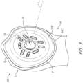
- FIG 3 shows a stemless humeral anchor 10E that can include any of the features of any of the other anchors disclosed herein.
- the stemless humeral anchor 10E includes a second end 14 configured to be disposed at the face F.
- the stemless humeral anchor 10E includes a first end (not shown) but in Figure 3 the stemless humeral anchor 10E is illustrated in the resected head of the humerus H so the first end is embedded in the bone and not shown.
- the first end can be similar to that of any of the foregoing anchors.
- the stemless humeral anchor 10E has a mating portion 16 that is accessible from the second end 14. A recess 18 is formed in the mating portion 16.
- the recess 18 is configured to receive a projection of an articular component to mate therewith.
- the recess 18 and the mating portion 16 extend along a longitudinal axis LA as shown.
- the stemless humeral anchor 10E includes a collar 20E that is adapted for a specific patient based upon pre-operative characterization, e.g., imaging as discussed above.
- the collar 20E extends transverse to the longitudinal axis LA toward an outer periphery of the stemless humeral anchor 10E.
- the outer periphery of the collar 20E is configured to reduce stress shielding.
- the collar 20E can have a shape that closely matches the shape of the perimeter RP of the face F at the resection plane of the humerus H.
- the collar 20E can match the size of the perimeter RP, e.g., can be large enough to extend to or nearly to the perimeter RP of the face F when the stemless humeral anchor 10E is coupled with the specific patient's humerus H.
- the collar 20E is configured such that when properly applied to the patient a maximum gap threshold is not exceeded. In other words, the collar 20E can be configured to achieve a maximum gap below a specific amount.
- the maximum gap can be applied to a zone of the humerus H that is subject to erosion due to stress shielding as discussed in connection with Figure 1A . In some cases, the maximum gap can be applied to the entire circumference of the stemless humeral anchor 10E.
- the collar 20E can allow for lager gaps between the outer periphery thereof and the perimeter RP of the face F in zones not subject to stress shielding erosion but can be configured to assure a gap of less than 4 mm therebetween at the medial calcar MC or other zone that is subject to stress shielding erosion. In certain embodiments, the collar 20E is configured to assure a gap of less than 2 mm between the outer periphery thereof and the perimeter RP of the face F at the medial calcar MC or other zone that is subject to stress shielding erosion. In certain embodiments, the collar 20E is configured to assure a gap of less than 1 mm between the outer periphery thereof and the perimeter RP of the face F at the medial calcar MC or other zone that is subject to stress shielding erosion.
- Figure 3 shows that the perimeter RP can be rotationally asymmetric. That is, anterior and posterior halves of the perimeter RP need not match each other. Thus, the placement of the stemless humeral anchor 10E should be rotationally aligned for the specific patient. If proper rotational alignment is not provided, the eccentric shape of the collar 20E will not properly match that of the perimeter RP of the face F. Accordingly, in methods of applying the stemless humeral anchor 10E care should be taken so that the rotational position of the collar 20E to the perimeter RP is properly provided.
- Figures 4 and 10 show the shoulder assembly 100 applied to a shoulder joint.
- the assembly 100B and various modified embodiment thereof can be adapted for a specific patient based upon pre-operative analysis of that patient's bone, e.g., CT scan, MRI, or X-ray.
- the assembly 100B can provide secure stemless connection to the humerus H.
- the shoulder assembly 100B provides for simple implantation because a base member thereof can be directly threaded into cancellous bone without being mated to another pre-placed base member.
- the shoulder assembly 100B can be fully retained within a head h of the humerus H.
- Figure 10 shows that the distal-most portion of the assembly 100 preferably can be disposed in the humeral head h.
- the assembly 100 does not have a stem or other member that protrudes beyond the head h into a medullary canal of the humerus. This approach is less invasive and simpler than procedures involving placement of a stem in a medullary canal.
- the assembly 100 may be recessed within the humeral head of the humerus H such that a proximal face 105 the assembly 100 is flush with respect to a cut surface of the bone.
- a proximal portion of a humeral assembly can be configured to be assembled onto the resection surface following a patient specific resection as discussed in connection with Figures 11-11B .
- Figure 5 shows that the assembly 100 includes a base member 104 and a locking device 108.
- the base member 104 is advanced into a bony structure such as cancellous bone in use. As discussed further below a bone surface may be exposed by resection or reaming, followed by threading of the base member 104 into a newly exposed bone surface.
- the assembly 100 also includes the locking device 108.
- the locking device 108 includes a plurality of arms 110.
- the arms 110 extend outward or distal from proximal support 132.
- the arms 110 can include a first arm, a second arm, and a third arm.
- the arms 110 can be circumferentially spaced equal distances from each other, e.g., about 120 degrees apart in one embodiment.
- the arms 110 include three arms, with two of the three arms spaced 90 degrees from each other and a third arm spaced 135 degrees from one of the other two arms.
- the locking device 108 may include four or more arms 110. If the arms 110 include four arms, the arms can be circumferentially spaced 90 degrees apart. If the arms 110 include two arms, the arms can be circumferentially spaced 180 degrees apart.
- the arms 110 are advanced through apertures 124 in the base member 104. In one embodiment, it should be noted that the number of arms 110 corresponds to an equal number of apertures 124. When so advanced, the arms 110 are disposed within the base member 104 in a manner that the arms 110 cross a space between portions, e.g., successive portions, of the base member 100.
- the arms 110 When so positioned, the arms 110 are also disposed within bone. Thus, two zones of the arms 110 can cross successive or adjacent portions of the base 104 and an intervening portion of the arms 110 can cross bone in a space between the successive or adjacent portion of the base. In this position, the arms 110 control, e.g., resist, rotation of the base member 104 relative to the bone such that the shoulder assembly 100 is secured against backing out of the bone upon implantation.
- Figure 5 also shows that the locking device 108 also includes a proximal support 132.
- the proximal support 132 is coupled with the arms 110 in a manner discussed further below.
- the proximal support 132 has a central aperture 136 disposed within an inner periphery thereof and extends outward from the central aperture 136 to an outer periphery 135.
- the inner and outer periphery of the proximal support 132 are received in a recess 140 formed in the base member 104.
- the recess 140 and the proximal support 132 are configured such that a flush connection is provided between the proximal support 132 and the proximal face of the base member 104.
- the proximal support 132 can be connected to the base member 104 in an at least partially recessed position in the proximal face of the base member as discussed further below in connection with Figure 9A .
- Figures 5 and 6B show that the proximal face of the base member 104 can include a raised inner portion 148 and a raised outer portion 152.
- the outer raised portion 152 extends around an outer periphery 154 of the base member 104.
- the raised portion 148, 152 are proximally oriented projections relative to a recessed surface 156.
- the recessed surface 156 can be disposed distally of one or both of the inner portion 148 and the outer portion 152.
- the raised inner portion 148 can define an aperture for access into the recess 102, which is configured for mating with articular components as discussed below.
- Each of the raised inner portion and the raised outer portion 148, 152 can comprises annular structures.
- the recessed surface 156 can comprise an annular portion.
- the apertures 124 can be formed in the recessed surface 156. In one embodiment the apertures 124 extend radially between the inner raised portion 148 and the outer raised portion 152. The apertures 124 can extend from the inner raised potion 148 to the outer raised portion 152.
- the proximal face of the base member 104 also can include a tool interface 158 that enables the base member to be advanced by an inserter into bone, as discussed below in Figure 17 .
- the tool interface 158 includes three notches in an inward side of the outer raised portion 152.
- the tool interface 158 can include apertures in the recessed surface 156, notches in the inner raised portion 148, projections from any surface of the proximal face of the base member 104 or any combination of these features.
- the tool interface 158 can provide access for a removal tool to engage the locking device 108.
- the locking device 108 includes a spring arm 168 and a removal tool can be applied at the tool interface 158 to compress the arm 168 to disengage the locking device from the base member 104.
- a removal tool can be applied at the tool interface 158 to compress the arm 168 to disengage the locking device from the base member 104.
- an inserter tool can engage one or more apertures 124 in the base member 104 upon insertion.
- the locking device can have an engagement feature 164 disposed on the proximal support 132 that is adapted to engage a corresponding feature on the proximal face of the base member 104.
- the engagement feature 164 can include an actuatable member that can move into a secure position relative to the recess 140 of the base member 104.
- the engagement features 164 can include a spring arm 168 to engage an overhang of the recess 140.
- one embodiment comprises a plurality of actuatable members, e.g., a plurality of spring arms 168.
- the spring arms 168 can be spaced apart, e.g., providing equal angle separation between adjacent spring arms 168. In one embodiment, the number of spring arms 168 matches the number of arms 110. Each spring arm 168 can be spaced apart from each arm 110 as discussed further below.
- a serration 172 is provided between the arms 110 of the locking device 108 and the base member 104 as discussed in greater detail below in connection with Figure 9B .
- the serration 172 is an example of a one-way connection that can be provided between the arms 110 and the base member 104.
- Other one-way connections can be provided in addition or in place of the serration 172, such as a ratchet, a barb, or one or more spring arms.
- Figures 5-6D show further details of embodiments of the base member 104.
- the base member 104 can include various features described in PCT publication WO2016/094739 .
- the base member 104 has a first end 204, a second end 208 and a body 212 that extends between the first end 204 and the second end 208.
- the base member 104 can comprise a length L between the first end 204 and the second end 208 that is less than a dimension of an articular surface of typical epiphysis to a medullary canal of a typical humerus.
- the first end 204 can be disposed within the epiphysis when the second end 208 is at a surface of the bone, as shown in Figure 10 .
- the second end 208 can be disposed at or on a superior medial resection plane of a humerus while the first end 204 is well within the epiphysis. This enables the first end 204 to stop short of a medullary canal of the humerus when the base 104 is fully implanted, which allows the bone between the first end 204 and the medullary canal to remain unaltered and also simplifies the procedure to the extent that any normal access to and preparation of the medullary canal is not needed.
- the length L can be between about 15 mm and about 30 mm, between about 18 mm and about 25 mm, between about 18 mm and about 24 mm, between about 21 mm and about 27 mm, between about 24 mm and about 29 mm.
- the length L can be about 18 mm, about 21 mm about 23 mm, about 24, mm about 26 mm and about 29 mm.
- at least a portion of the assembly 100 is patient specific.
- the length L can be defined for a specific patient based on pre-operative planning, such as using two dimensional or three dimensional imaging.
- the base member 104 can thereafter be manufactured for that patient based on the determined dimension L.
- the base member 104 can include a collar 220 and a helical structure 224.
- the helical structure 224 is disposed about a cylindrical portion 260 of the body 212 of the base member 104.
- the helical structure 224 extends directly from the body 212 and may be considered threads of the body 212.
- the helical structure 224 can include one or a plurality of threads, e.g., two, three, four, or more threads, disposed between the first end 204 and the second end 208.
- the threads can start adjacent to the first end 204 and extend toward, e.g., entirely to the second end 208.
- Figure 6 shows that the threads or other helical structure 224 can end at or adjacent to the collar 220.
- the threads or other helical structure 224 can have inner portions 240 disposed at or on the body 212 about the recess 102 and outer portions 244 disposed along the periphery of the base 104.
- Figure 6 shows that the helical structure 224 has a width defined as the distance between the inner and outer portions 240, 244 that is large, e.g., comprising more than one-quarter of, e.g., about one-third of, the width of the base 104 at a given location.
- These large threads or other helical structure 224 ensure large purchase in the bone. Large purchase provides strong resistance to pullout even prior to any bone ingrowth into the surfaces of the shoulder assembly 100.
- one or more surfaces of the shoulder assembly 100 that are in direct contact with bone may be textured e.g., coated or layered with a porous material in order to accelerate tissue ingrowth such as bony ingrowth Therefor good initial resistance to pull-out is advantageous for the patient.
- At least one turn of a thread or other helical structure 224 completely surrounds the recess 102, e.g., by completely surrounding the body 212, in some embodiments.
- Figures 6A-1 and 6A-2 show that additional features of the base 104 can be made patient specific.
- Figure 6A-1 shows a base 104A with a first end 204, a second end 208 and a body 212 that extends between the first end 204 and the second end 208, similar to the base 104 discussed above.
- the base 104A has a helical structure 224A that is made patient specific. That is, pre-operative information such as CT scan, MRI scan, X-ray or other assessment of the proximal humerus is conducted. That assessment can reveal patient specific characteristics of the portion of the proximal humerus to which the base 104A will be coupled.
- that assessment can identify the location of a resection along the humerus H (see Figure 1 ) or volume, density, or location of bone between the exposed face F and the medullary canal or the lateral side of the proximal humerus. Based on this information, the configuration of the body 212 can be altered.
- the helical structure 224A can comprise threads that have a smaller thread pitch than is provided in the threads of the helical structure 224. Smaller thread pitch is suitable for a patient having denser than average bone matter disposed beneath the exposed face F.
- the thread pitch can be in the range of 3-10mm depending on the bone quality. A thread pitch of 5mm could be suitable for average bone density. A thread pitch of 3 mm could be suitable for high bone density.
- the helical structure 224A can have a transverse extent (e.g., from the inner portions 240 to the outer portions 244 thereof that is larger than in the helical structure 224.
- the maximum transverse extent in the helical structure 224A is greater than the maximum transverse extent in the helical structure 224.
- Larger transverse extent is suitable for a patient having poor bone quality, larger humeral heads, e.g., with larger surface area at the exposed face F and/or with greater volume of bone beneath the exposed face F.
- the transverse extent could be in a range of between 5 mm and 15 mm depending on the patient.
- FIG. 6A-3 shows a base 104C that also can be made for a specific patient based on pre-operative analysis of the patient's bone.
- a helical structure 224C can be formed or shaped in a patient specific manner. The helical structure 224C can extend from a first end 204 and to a second end 208 of the base 104C. The form of the helical structure 224C can change between the first end 204 and the second end 208.
- the transverse extend of each successive turn can be selected based upon the patient's bone disposed laterally and inferiorly of the exposed face F to be formed by resection. If the perimeter of the humeral head in planes adjacent and parallel to the exposed face F in the direction of the arrow A in Figure 1A rapidly reduces a profile 225 can be formed to match that rapid change. If the perimeter of the humeral head in planes parallel to the exposed face F in the direction of the arrow A in Figure 1A more gradually reduces a profile 225 can be formed to match that more gradual change.
- the profile 225 of the helical structure 224C can be made patient specific to enhanced fixation to the bone and/or to avoid over-filling the humeral head with the helical structure.
- the body 212 surrounds the recess 102, which is configured to mate with an articular component, such as humeral head or a glenoid sphere.
- the body 212 includes a cylindrical portion 260 within which the recess 102 is disposed.
- the cylindrical portion 260 can have any suitable outside configuration, such as including a textured surface that is well suited to encourage bony ingrowth.
- the cylindrical portion 260 can include a generally tapered profile in which a portion at or adjacent to the first end 204 of the base member 100 has a first width and a portion at or adjacent to the second end 208 of the base member 100 can have a second width, the second width being greater than the first width.
- the cylindrical portion 260 is generally rounded and formed a blunt but tapered profile.
- the cylindrical portion 260 can have a flat distal surface in some embodiments.
- Figure 10 shows that the cylindrical portion 260 can include a plurality of layers.
- an inner layer 264 can be disposed adjacent to the recess 102.
- the inner layer 264 can include the surface surrounding the recess 102 and can extend away from that surface toward an outer surface of the cylindrical portion 260.
- an outer layer 268 can be disposed adjacent to the outer surface of cylindrical portion 260.
- the outer layer 268 can extend from the external surface of the cylindrical portion 260 toward the recess 102.
- the outer layer 268 is formed directly on the inner layer 264 although other arrangements are possible as well.
- the outer layer 268 can be a porous structure that is suitable for bony ingrowth.
- Figure 10 also shows that a tool interface 272 can be disposed at or adjacent to the first end 204 of the base member 104.
- the tool interface 272 can include a threaded portion that can mate with a delivery tool, as discussed further below.
- a lumen 276 can be provided at the first end 204 such that access can be provided from the first end 204 through the wall of the cylindrical portion 212 into the recess 102.
- the lumen 276 and recess 102 together provide access for a K-wire or other guiding device such that implanting the base member 104 can be controlled in an appropriate manner.
- the collar 220 can be disposed at or can comprise the second end 208 of the base member 104.
- the collar 220 can have a transverse width, e.g., a diameter that is suitable for a given condition.
- the diameter of the collar 220 can be selected such that the entire outer periphery of the base 104 is within the bone exposed by resection and/or recessed into such an exposed bone portion, e.g., as illustrated in Figures 11-15 .
- the collar 220 has a diameter of more than about 25 mm and less than about 60 mm.
- the collar 220 can have a diameter of between about 30 mm and about 45 mm.
- the collar 220 can have a diameter of about 33 mm in one embodiment.
- the collar 220 can have a diameter of about 42 mm in one embodiment. Making the collar 220 as large as possible within such bounds provides for better load transfer between the collar 220 and the humerus H.
- the diameter of the collar 220 can be defined for a specific patient based on pre-operative planning, such as using two dimensional or three dimensional imaging.
- the base member 104 can thereafter be manufactured for that patient based on the determined diameter of the collar.
- the diameter of the collar 220 can be selected such that the collar covers the cortical rim exposed by resection.
- the collar 220 can attach to or can be integrally formed with the cylindrical portion 260 of the body 212.
- the collar 220 comprises a transverse flange 290 that extends outward of the recess 102 that is also disposed at the second end 208.
- An inner portion of the flange 290 can be disposed adjacent to the recess 102 and can include the inner raised portion 148.
- An outer portion of the flange 290 can be disposed outward of the inner portion.
- the flange 290 can define the proximal face of the base member 104.
- the flange 290 can accommodate the proximal support 132 of the locking device 108.
- Figure 9A shows that in some embodiments, the flange 290 can at least partially surround a space 294 disposed therein to receive a portion of the locking device 108.
- the space 294 can be an annular recess located proximal of the recessed surface 156 and between the inner portion 148 and the outer portion.
- the space 294 can be bounded by an inner edge of the outer portion 152 and an outer edge of the inner portion 148.
- the flange 290 can engage the spring arm 168 of the locking device 108 in the space 294 such that the locking device 108 will not be inadvertently disengaged from the base 104 and protrude from or be removed from the space 294.
- Figures 5 and 10 show that in some embodiment, the shoulder assembly 100 includes a pathway 300 that projects distally of the collar 220.
- the pathway 300 can comprise a first pathway.
- the shoulder assembly 100 can include a plurality of pathways, 300 with each pathway corresponding to an arm 110 of the locking device 108.
- Figure 6B shows that the base 104 can define a plurality of such pathways, e.g., two or three pathways configured to receive corresponding arms 110. There can be four or more than four pathways 300.
- the pathway 300 can have a first end located at the opening or apertures 124 in the collar 220.
- the pathway 300 can continue down through the base member 104.
- Figure 6C shows that the pathway 300 can have one or more segments disposed through the helical structure 224.
- a first segment 300A of the pathway 300 extends from the aperture 124 to a first portion, e.g., a proximal-most turn or portion of the helical structure 224 immediately distal of the collar 220, e.g., immediately distal of one of the apertures 124.
- a second segment 300B of the pathway 300 extends from the first segment 300A to a second turn or portion of helical structure 224 immediately distal of the first portion of the helical structure.
- a third segment 300C of the pathway 300 can extend from the second segment to a third turn or portion of helical structure 224 immediately distal of the second portion of the helical structure 224.
- Figures 6B and 6D illustrate that at specific locations along the length of the base 104 from the first end 204 to the second end 208, the pathway 300 can have a first boundary 304 corresponding to an outer surface or layer of the cylindrical portion 260, for example corresponding to a surface of the outer layer 268.
- the pathway 300 can have a second boundary 308 at a same location along the length of the base 104 from the first end 204 to the second end 208 formed by an adjacent portion of helical structure 224.
- the second boundary 308 can include a U-shaped opening in the inner portion 240 of the helical structure 224.
- the U-shaped opening in the inner portion 240 can extend across the width of the helical structure toward the outer portion 244 of the helical structure 224.
- the U-shaped opening can extend 25%, 35%, 45%, 50%, 60%, 70%, 75% or up to 90% of the distance across the width of the helical structure 224 from the inner portion 240 toward the outer portion 244.
- the helical structure 224 has a tapered configuration in which transverse distance between opposite sides of the helical structure 224 is decreased in the direction of the first end 204 compared to the same dimension toward the second end 208.
- the length of the U-shaped opening in successive portions of the helical structure 224 in the direction toward the first end 204 is progressively less in some embodiments.
- the width bounded by a turn of the helical structure 224 and the cylindrical portion 260 in the first segment 300A of the pathway 300 can be greater than the width bounded by a turn of the helical structure 224 and the cylindrical portion 260 in the second segment 300B.
- the width in the second segment 300B can be greater than the width in the third segment 300C bounded by a turn of the helical structure 224 and the cylindrical portion 260.
- the pathway 300 can extend through one or more spaces between adjacent threads of the helical structure 224.
- the pathway 300 can comprise two or more segments surrounded by portions of the base member 104 and at least one exposed segment ES.
- the exposed segments comprise portions of the first and second segments 300A, 300B and between the second and third segments 300B, 300C in some embodiment.
- the exposed segments ES are exposed in that, unlike the segments 300A, 300B, 300C, the exposed segments of the pathway 300 are not enclosed circumferentially and thus bone disposed within the helical portion 224 can directly contact the arms 110 in the exposed segment. As such the pathway 300 is bounded by bone matter in the exposed segments.
- Figures 5 , 7 and 8 show the locking device 108 in detail.
- the locking device 108 has a proximal support 132 and a first arm 110 that projects distally of the proximal support 132.
- the proximal support 132 includes an inner periphery 358, an outer periphery 362 and an annular member 366 disposed therebetween.
- the inner periphery 358 surrounds the central opening 136, which is sized to receive the inner raised portion 148 of the base member 104 if present.
- the annular member 366 is configured to be received in the recess 140, as discussed above.
- the first arm 110 is configured to be disposed in the first pathway 300.
- the pathway 300 projects distally of the collar 220.
- the first arm 110 is disposed distal of the collar 220 when the proximal support 132 is disposed adjacent to a proximal side of the collar 220 and the first arm 110 is in the first pathway 300.
- the first arm 110 includes an outer edge 370, an inner edge 374 and a span 378 disposed therebetween.
- the first arm 110 includes a first end 382 disposed away from the support 132 and a second end 386 disposed adjacent to and in some cases directly coupled to the support 132.
- the first arm 110 can be tapered, for example with the outer edge 370 approaching the inner edge 374 in the direction toward the first end 382 and/or with the outer edge 370 diverging away from the inner edge 374 in the direction toward the second end 386.
- opposite faces 390 of the span 378 are also tapered with at least one of, e.g., both of, the opposite faces 390 approaching a longitudinal mid-plane M of an arm 110.
- the tapering of the arms between the edges 370, 374 facilitates providing a tapered profile in the base member 104.
- the tapering of the arms between the edges 370, 374 sometimes referred to herein as a radial taper, facilitates insertion of the first end 382 into the aperture 124 because the first end 382 is much narrower in the dimension between the edges 370, 374 than the aperture 124 is in the radial direction.
- the tapering of the arms 110 between the faces 390 sometimes referred to herein as a circumferential taper, facilitates insertion of the first end 382 into the aperture 124 because the first end 382 is much narrower in the dimension between the faces 390 than the aperture 124 is in the circumferential direction.
- At least one of the circumferential and radial tapers of the arms 110 enables the locking device 108 to easily be advanced through bone matter that is disposed along the pathway 300.
- the first arm 110 is disposed through bone in the space between successive portions of the helical structure 224, e.g., in the first segment of the path 300 and in the second segment of the path 300, when the humeral shoulder assembly is implanted.
- the span 378 and/or other parts of the arms 110 can be porous to enhance bony ingrown when the assembly 100 is implanted.
- the porous properties can be provided by a porous metal surface or structure or by other porous layers disposed on an underlying layer of metal or another material. At least the widening of the arms 110 toward the second end 386 increases the purchase of bone in the widened area, e.g., in the first segment of the path 300 and also in the second segment of the path 300 compared to an arm that is not tapered.
- the arms 110 are not tapered in the radial direction.
- the arms 110 can have a constant radial dimension between the edges 370 and 374 at a length between, e.g., along the entire length between, the first end 382 and the second end 386.
- the arms 110 are not tapered in the circumferential direction.
- the arms 110 can have a constant circumferential dimension between the first end 382 and the second end 386.
- the locking device 108 facilitates retaining the base member 104 in the bone at least by opposing, and in some cases completely preventing, rotation of the base member that would cause the base member to back out of the bone into which it has been advanced. Additionally, in some embodiments, it is beneficial to oppose, and in some cases completely prevent, axial movement of the locking device 108 away from the base member 104. At the extreme, such movement could result in the arms 110 of the locking device 108 completely coming out of the pathways 300 and, indeed, out of the base member 104 completely. It also may be desirable to prevent even lesser movements of the locking device 108 relative to the base member 104.
- a distal face 402 of the annular member 366 may be positioned in direct contact with a proximal face 404 of the transverse flange 290. Such contact can correspond to a proximal face 406 of the annular member 366 being distal of a proximal face 408 of the raised outer portion 152.
- FIGs 8 and 9A illustrate various embodiments of axial locking configuration that can be provided in the shoulder assembly 100.
- An axial locking configuration can include the engagement feature 164 disposed on the proximal support 132.
- the spring arm 168 of the engagement feature can include a first end 420 disposed away from the annular member 366 and a second end 424 coupled with the annular member 366.
- the spring arm 168 also has an elongate portion 428 that extends between the first end 420 and the second end 424.
- the elongate portion 428 preferably has an arcuate form and can, in some embodiments, have the same curvature as a portion of the annular member 366 adjacent to the second end 424.
- the elongate portion 428 can be separated from the annular member 366 along a radially inner edge 432 of the elongate portion 428 by a gap G.
- the gap G and the length of the elongate portion 428 can be such that the first end 420 can be moved sufficiently to allow for a snap-fit connection as discussed further below.
- the first end 420 of the spring arm 168 has a deflector 436 that facilitates movement of the elongate portion 428 and specifically movement of the first end 420.
- Figure 9A shows that the deflector 436 can include an angled surface 460 that initially engages a corresponding angled surface 464 on the base member 104, e.g., on the raised outer portion 152 at the proximal face of the base member.
- the annular member 366 eventually is received in the space 294.
- the angled surfaces 460, 464 engage each other, which engagement causes the deflection of the first end 420 of the spring arm 168.
- the first end 420 is deflected radially inwardly such that the gap G is reduced at least at the first end 420.
- a proximal facing surface 472 moves to a position distal of a distal facing surface 476.
- the spring arm 168 resiliently moves the deflector 436 back to the configuration shown in Figure 8 .
- the proximal facing surface 472 is distal of and aligned with, e.g., positioned under, the distal facing surface 476, as shown in Figure 9A .
- the proximal facing surface 472 blocks the distal facing surface 476 from moving proximally.
- the surfaces 472, 476 prevent the locking device 108 from disengaging from the base member 104.
- the tooling interface 158 allows an extraction tool to be disposed between the raised outer portion 152 and the spring arm 168.
- the extraction tool can apply a radially inward force on an outer periphery of the elongate portion 428 of the spring arm 168. Compression of the spring arm 168 decreases the gap G as the proximal facing surface 472 is moved radially inward of the distal facing surface 476. Once the first end 420 is entirely radially inward of the distal facing surface 476, the engagement feature 164 is disengaged from the base 104. If more than one spring arm 168 is provided some or all of the spring arms can be compressed to allow the locking device 108 to be withdrawn from the base 104.
- Figure 9B shows additional axial locking configurations that can be provided in the shoulder assembly 100.
- axial locking can occur at an interface 490 between one or more of the arms 110 and one or more of the pathways 300.
- the serrations 172 discussed above can be provided at the interface.
- serrations 172 are disposed along the pathway, e.g., on a surface of the cylindrical member 212 and/or on a surface of the helical structure 224. The serrations 172 can be placed at both the surface of the cylindrical member 212 and at the helical structure 224.
- the serrations 172 could be provided on a surface of the arm 110, e.g., on one of the outer edge 370, the inner edge 374, and/or on one of the faces 390.
- the serrations 172 allow for relatively easy insertion of the arms 110 but bite into and oppose withdrawal of the locking device 108 to oppose axial disengagement of the locking device 108 from the base member 104.
- the serrations 172 can be disposed along the entire length of the interface between the arms 110 and the base member 104 or just at a position where the base member 104 and the locking device 108 are fully engaged.
- Figures 11-19 illustrate various techniques for implanting the shoulder assembly 100 in a humerus H.
- the method illustrates placement in a proximal end of the humerus H, e.g., in the humeral head h.
- Figure 11 illustrates an early step of one embodiment of a method including resecting the head h of the humerus H.
- a guide 600 Prior to resecting the head h of the humerus H a guide 600 is applied to the humerus H.
- the guide 600 includes structure for mating with the humerus H and the head h, for example, a plate 604 to mate with the humerus H and pins 608 to mate with the head h.
- the guide 600 also has a slot 612 to guide a saw to cut the humerus H to expose cancellous bone of the head h.
- Figure 12 shows that after resecting the head h of the humerus H the size of the head is evaluated with a template 620.
- a guide pin 624 is first placed in the resected head h.
- the template 620 is advanced over the guide pin 624 into contact with the resected head.
- the size of the resected head h is determined from the template 620.
- the guide 600 can be a reusable guide that is not specific to any particular patients.
- the guide 600 is formed with reference to a specific patient. That is, the guide 600 can be formed to mate with the patient, such as by conforming in whole in part on a bone facing side to the shape of the bone as observed or measured using imaging or other devices prior to surgery.
- Figures 11A-11B show that in some cases, a resection surface RX can be formed in a patient specific manner using a patient specific humeral cutting guide 600A.
- the humeral cutting guide 600A includes a first portion 602A, a second portion 604A, and a third portion 606A.
- One or more, e.g., all, of the first portion 602A, the second portion 604A, and the third portion 606A can be configured to contact specific parts of the humerus H.
- each of these portions can have a substantial negative surface 608A.
- the surfaces 608A can be formed with reference to a pre-operative imaging of the patient's humerus, e.g., using CT scans, MRI, or X-ray information.
- the surfaces 608A can be configured such that the cutting guide 608A fits only in a specific location and orientation on the humerus H.
- the guide 600A also includes a cutting plane 610A.
- the cutting plane 610A is disposed at a specific location and orientation such that the resection Rx of the humerus H is at a pre-planned location and orientation.
- the resection Rx when formed using the cutting plane 610A will have a pre-planned peripheral shape.
- the pre-planned shape of the periphery of the resection Rx can be accounted for in forming portions of humeral assemblies and implants that engage the resection Rx.
- the guide 600A can have one or a plurality of apertures 612A to secure the guide 600A to the humerus H.
- the guide can have one or a plurality of apertures 614A that can be used to place guide pins or other members to facilitate one or more subsequent steps of preparing the humerus H or implanting components.
- Figure 13 shows that the resected surface of the head h can be prepared, such as by using a planar or a reamer 632.
- the reamer 632 also can be guided by the guide pin 624.
- the reamer 632 can be used to form a recessed surface S to which the assembly 100 will be applied after further preparation.
- Figure 14 shows a step of measuring depth of the recessed surface S. The purpose of this step is to provide a secondary confirmation that the assembly 100 will fit into the metaphysis without striking the lateral cortex. While the analysis of Figure 12 indicates a diameter of base member 104 that could be used, the depth gauge 637 of Figure 14 provides a depth sizing that confirms a maximum length, e.g., depth, that would fit in the recessed surface S surgeon is instructed to take the smaller of the two sizes determined.
- Figure 15 illustrates that following depth measurement, a bore B is formed in the surface S in initial preparation of the surface S to receive the shoulder assembly 100.
- the bore B is formed using a drill 640.
- the drill 640 can be a convention cannulated design configured to be advanced over the guide pin 624.
- the drill 640 can be configured as a universal drill with a modular stop to obtain variable lengths.
- the drill 640 can be one of a plurality of drills, each drill of the plurality having a different size as appropriate. In certain methods, the process of forming the bore B and reaming the surface S as discussed above in connection with Figure 13 can be combined.
- a drill 640 can have a reaming feature disposed proximally of the bore forming features such that a continuous motion toward the surface formed using the guide 600 can initially form the bore B and subsequently form the surface S.
- the humerus H may be prepared to receive the press-fit embodiments disclosed herein, e.g., in Figures 2-3.
- Figure 16 shows that once the bore B has been formed, the bore B can optionally be tapped to be prepared to receive the base member 104 of the shoulder assembly 100.
- the tapping process can be achieved by using a helical tap component 648 that is advanced over the guide pin 624.
- the helical tap 648 can follow the form of the helical structure 224 of the base member 104 such that the base member 104 can be easily advanced into the bore.
- the helical tap 648 can be secured to a shaft 654 that can be mounted to a motor driven drill or to a hand tool.
- Figure 17 shows that in some embodiments discussed herein a trunnion or other transverse extender can be coupled with the face F of the humerus H at the resection plane.
- the trunnion is illustrated by a dashed line labeled Tr.
- the trunnion can be applied after the bore B and/or the recessed surface S is or are formed and, optionally, after the tapping process.
- the trunnion can be applied by gentle pressure laterally against the face F or against the face F and the recessed surface S by hand or using a dedicated tool.
- the trunnion can be placed prior to inserting the base member 104 (or any of the other base members disclosed herein that can be mated to the trunnion).
- Figure 17 shows a step of inserting the base member 104.
- the base member 104 is secured to a distal end of an inerter 662.
- the inserter 662 has a stem 666 that is threaded at a distal end thereof.
- the threads of the stem 666 can be mated with the tool interface 272 (see Figure 10 ), e.g., with threads of the tool interface.
- the stem 666 is enlarged at a mid-section thereof providing at least a shoulder that can mate with the inner raised portion 148 of the base member 104.
- a separate member 668 of the inserter 662 is advanced over the stem 666 to the tool interface 158, and the force of advancing the base member 104 thus can be applied through the tool interface 272, through the inner raised portion 148, through the apertures 124 or through more than one of these (or other) features of the base member 104.
- Splines 672 provide for good grip by the surgeon so that the surgeon can easily engage the stem 666 to the tool interface 272.
- a driver with a torqueing device at a proximal end couples at its distal end directly with the tool interface 272, through the inner raised portion 148, through the apertures 124 or through more than one of these (or other) features of the base member 104 to enable more direct transfer of torque to the base member.
- Preferably inserting the base member 104 into the bone includes placing the outer periphery 154 in the recessed surface S, e.g., at least partially recessed into the resected bone of the humerus H.
- the dashed line Tr shows the outer periphery of a trunnion that can optionally be placed between the face F and the base member 104 (or other base members described herein).
- the line Tr shows that the trunnion where provided cover all or substantially all of the face F between the base 104 and the perimeter RP of the humerus H.
- Figure 18 shows that after the base member 104 has been inserted, the locking device 108 can be inserted.
- the base member 104 is inserted by a rotation of the member by rotation of the inserter which is directly connected to the base member as discussed above in connection with Figure 17 .
- the locking device 108 is inserted along the pathway by linear translation, e.g., by a movement along a generally straight axis without rotation.
- An inserter 680 is provided that has an enlarged head 682 that can be secured to or can just rest upon the proximal face of the annular member 366 of the proximal support 132. The head 682 is then advanced over the splines 672 of the stem 666, with the stem 666 acting as an axial guide.
- the first end 382 of the arm 110 or arms is aligned with the aperture 124 or apertures if more than one.
- the arms 110 are radially and circumferentially tapered and the apertures 124 are sized for the wider proximal end of the arms.. This configuration helps guide the locking device 108 into the base member 104.
- the proximal end 684 of the inserter 680 in configured for impacting the locking device 108 into the base member 104. Once the locking device 108 is in place the base member 104 is fixed and will not back-out by subsequent rotation.
- the locking device 108 assures that the level of compression by the trunnion or by an enlarged flange, transverse plate or collar configured to reduce stress shielding initially provided by full advancement of the base 104 against the trunnion, flange, transverse plate or collar will be maintained such that stress shielding will be reduced, minimized, or eliminated.
- Figure 19 shows later steps of a method of implanting an anatomic shoulder prosthesis.
- an anatomic articular component 86 can be coupled with the recess 102.
- the anatomic articular component 86 comprises a convex surface 90, analogous to the natural anatomy.
- the anatomic articular component 86 is placed with an impactor 684A.
- the insertion and impaction functions illustrated in Figures 18 and 19 could be carried out by the same device.
- a contoured face to contact the surface 84 could have a portion configured for inserting the locking device 108 and/or the tray 94.
- Figure 19 shows an alternative step of a method of implanting a reverse shoulder prosthesis.
- a reverse articular component 88 can be coupled with the recess 102.
- the reverse articular component 88 includes a tray 94.
- the tray 94 can be coupled with an articular component 96 comprising a concave surface for articulating with a glenoid sphere disposed on a glenoid of a scapula (discussed further below).
- the tray 94 is placed with an impactor 684A.
- the reverse shoulder prosthesis including the shoulder assembly 100, the tray 94 and the articular component 96 is shown in Figures 21A and 21B .
- a glenoid sphere 99 mated with a glenoid is shown in Figure 21B .
- the shoulder joint provides movement of the patient's arm by articulating the component 96 over the glenoid sphere 99.
- a trunnion illustrated by the line Tr can be provided between the appropriate articular component placed in the steps illustrated in Figures 18 and 19 to cover a portion of the resection Rx that is outlying relative to an outer periphery of the base 104 of the assembly 100.
- the trunnion can be made patient specific in various ways discussed further herein.
- the trunnion can be placed in compression against the resection Rx and can cover some or all of the portion of the resection Rx subject to erosion arising from stress shielding.
- the trunnion can be configured for the specific patient to extend medially and inferiorly to cover a reduce, minimize or eliminate stress shielding, e.g., of the medial calcar MC, as discussed above.
- the locking device 108 is inserted at the same time as some or all of the reverse articular component 88 or at the same time as the anatomic articular component 86.
- the locking device 108 can be a separate component that is loaded onto an inserter or impacting tool that can be previously loaded with the reverse articular component 88 or the anatomic articular component 86.
- the locking device 108 can be a separate component that is loaded onto an inserter or impactor with, but relatively moveable to, the reverse articular component 88 or the anatomic articular component 86.
- the locking device 108 and the reverse articular component 88 can be formed as a monolithic structure that can be loaded together onto an inerter.
- the locking device 108 and the anatomic articular component 86 can be formed as a monolithic structure that can be loaded together onto an inerter.
- FIGS 22-26 illustrate a shoulder assembly 800 that is adapted for securement to a glenoid.
- the shoulder assembly 800 is similar to the shoulder assembly 100 described above, except as described differently below. Any feature discussed above can be substituted in and supplement the features of the shoulder assembly 800. The features of the shoulder assembly 800 can be substituted in and supplement the features of the shoulder assembly 100.
- FIG 22 shows that the shoulder assembly 800 can be implanted into a glenoid region g of a scapula SC.
- the shoulder assembly 800 includes a base member 804 and a plate member 808.
- the base member 804 has a medial end 816 and a lateral end 820.
- Figures 24-26 show that the base member 804 includes a body 812 that extends between the medial end 816 and the lateral end 820.
- a lumen 822 extends in the body 812 from the lateral end 820 toward and in some cases entirely to the medial end 816.
- a distal portion of the lumen 822 includes a threaded zone 823, discussed below.
- the base member 804 includes a helical structure 824, which is disposed along the body 812 between the medial and lateral ends 816, 820, respectively.
- the helical structure 824 extends from the medial end 816 to the lateral end 820 in some embodiments.
- a tool interface 826 is disposed lateral of a lateral end of the helical structure 824.
- the base member 804 includes a first pathway 830 accessible from the lateral end 820 of the base member 804.
- the first pathway 830 is directed toward the medial end 816 through the helical structure 824.
- the first pathway 830 can be located adjacent to an inner periphery of the helical structure 824, as discussed above.
- the first pathway 830 can be partly defined by an outer surface of the body 812.
- the first pathway 830 can be disposed generally transverse to the helical structure 824.
- the first pathway 830 extends in a space 832 between successive portions of the helical structure 824.
- a first segment 830A of the first pathway 830 is disposed through a proximal portion of the helical structure 824, a second segment 830B of the first path 830 is located medial of the first segment 830A, and a third segment 830C of the first path 830 is disposed medial of the second segment 830B.
- Figure 26A shows the segments 830A, 830B, 830C of the path 830 in more detail.
- Figure 26A also shows that the base member 804 can include one or more barbs 835.
- the barbs 835 are configured to facilitate softer material attachment.
- the internal portion of the base member 804 couples with a structure made of a soft material, such as polyethylene.
- a structure made of a soft material such as polyethylene.
- a convex articular surface may be coupled with the scapula using the base member 804.
- Another example is a reverse configuration with an inverse bearing surface (e.g. polyethylene glenoid sphere).
- the mode of connection between the base 804 and an articular or other component can include an interference fit between the barbs 835 and a projection of such component received in a space around which the barbs 835 are located, as described in connection with Figures 11A and 11B of WO2016/094739 .
- the barbs 835 can be replaced with mating threads, mating threads and fins and/or mating fins, as described in connection with Figure 5 of US20120221111 .
- the barbs 835 can be replaced by a groove and a C-ring or other deflectable member that spans between the base member 804 and an articular or other component as described in connection with Figures 4 and 5 of WO2014/067951 .
- the plate member 808 has a flange 842 and a first arm 846 that projects distally, medially away from or generally in a direction of implantation of the plate member 808 from the flange 842.
- the plate member 808 can have a second arm 846 that projects away from the flange 842.
- the first arm 846 is configured to be disposed in the first pathway 830 when the plate member 808 is disposed adjacent to the lateral end 820 of the base member 804.
- the first arm 846 is disposed through bone in the space 832 between successive portions of the helical structure 824 when the shoulder assembly 800 is implanted.
- the plate member 808 also includes a boss 850 that extends laterally of the flange 842.
- the boss 850 comprises an arcuate outer periphery 854 and an aperture 858 that provides access to a lumen 862 through the aperture 858.
- the lumen 862 is defined by a tapered surface 864 that mates with a glenoid sphere 870, as discussed below.
- the glenoid sphere 870 and the boss 850 are configured such that the glenoid sphere 870 coupled with the outer surface of the boss 850.
- the glenoid sphere 870 comprises a recess 874 disposed on a medial side and a convex side 878 disposed opposite the recess 874.
- the glenoid sphere 870 has a tapered surface 882 disposed within the recess 874.
- the tapered surface 882 is partly disposed in the recess 874 and partly extends medially of the recess 874.
- the tapered surface 882 is disposed on a projection 890.
- the boss 850 receives the projection of the glenoid sphere 870 therein.
- the tapered surface 864 on the boss 850 mates with the tapered surface 882 on the medial side of the glenoid sphere 870 to form a connection between the glenoid sphere 870 and the plate member 808.
- the mating tapered surfaces 864, 882 can form a Morse taper connection between the glenoid sphere 870 and the plate member 808.
- a fastener 910 is used to secure the glenoid sphere 870, the plate member 808, and the base member 804 together.
- the fastener 910 includes a medial end 914 with a threaded zone 918 and a lateral end 922.
- the lateral end 922 includes a tool interface 926.
- the connection between the components of the shoulder assembly 900 is shown in Figure 23 .
- the base member 804 can be advanced into the glenoid g following preparations similar to that discussed in connection with of Figures 11-16 .
- the plate member 808 can be advanced into the base member 804.
- the plate member 808 is advanced in a manner similar to the locking device 108.
- the arms 846 are advanced into the helical structure 824.
- the glenoid sphere 870 can be mated to the plate member.
- the projection 890 can be advanced into the lumen 862 (see Figure 26 ).
- the fastener 910 can be advanced relative to the projection 890 and mated with the threaded zone 823. Further advancing of the fastener 910 into the threaded zone 823 induces a friction fit, e.g., a Morse taper, at the tapered surfaces 864, 882.
- the threaded zone 918 of the fastener 910 engages first the threaded zone 902 of the glenoid sphere 870 and then mates with the threaded zone 823.
- the back-out of the fastener 910 is limited such that the lateral end 922 of the fastener 910 does not protrude outside of the convex side 878 of the glenoid sphere 870.
- lateral motion of the fastener 910 will be limited when a lateral end of the threaded zone 918 is disposed against a medial end of the threaded zone 902.
- the distance between the lateral end of the threaded zone 918 and the lateral end 922 of the fastener 910 will be less than the distance within the lumen 894 from the lateral end of the threaded zone 902 to the convex side 878 of the glenoid sphere 870.
- the disengaged state of the fastener 910 will not result in the lateral end 922 protruding from the convex side 878.
- the plate member 808 includes additional features for enhancing securement to the bone.
- the plate member 808 can includes one or more apertures 920.
- the apertures 920 can receive bone screws to enhance securement of the plate member 808 to the bone, e.g., to the scapula SC.
- the bone screw will lock into the apertures 920 by a thread engagement.
- the locking mechanism will be multidirectional providing the possibility to lock the bone screws at a variable angle from the axis of the flange 842.
- the medial side of the plate member 808 can includes a textured surface 924 e.g., coated or layered with a porous material in order to accelerate tissue ingrowth such as bony ingrowth.
- the plate member 808 could be manufactured by additive manufacturing to incorporate the porous surface 924.
- the assembly 800 could be used to secure a hard material (e.g. ceramic, pyrocarbon, or metal) glenoid sphere 99 to a glenoid
- a soft-material e.g. polyethylene, polyurethane, PEEK
- the assembly 800 could be used to secure an atomic glenoid.
- the assembly 800 could be used in other anatomy to achieve very secure connection to relatively shallow layers of bone, which can include cancellous bone that is exposed during a procedure.
- Figures 27-29 show a number of other applications for the prosthesis assemblies described herein.
- the shoulder assemblies 100, 800 can be applied to other bones and joints.
- Figure 27 shows that a proximal femur f can be fitted with a prosthesis assembly 100f similar to the prosthesis assembly 100.
- the prosthesis assembly 100f is different from the shoulder assembly 100 in that it would be configured more particularly for the proximal femur.
- Figure 28 shows that a distal humerus h or to a distal radius r can be fitted with a prosthesis assembly 100h, r similar to the prosthesis assembly 100.
- the prosthesis assembly 100h, r is different from the shoulder assembly 100 in that it would be configured more particularly for the distal humerus or radius.
- Figure 29 shows that a distal femur df and/or to a proximal tibia t can be fitted with a prosthesis assembly 100df, 100t similar to the prosthesis assembly 100.
- the prosthesis assemblies 100df, t are different from the shoulder assembly 100 in that they would be configured more particularly for the distal femur or proximal tibia.
- implant sizing such as threads external diameter, core diameter, overall length could be sized according to patient anatomy per pre-operative planning based on CT-scan, MRI or any other medical images modality.
- Figure 30 shows that a distal tibia dt and/or to a proximal talus tal can be fitted with a prosthesis assembly 100dt, 100tal similar to the prosthesis assembly 100.
- the prosthesis assemblies 100dt, tal are different from the shoulder assembly 100 in that they would be configured more particularly for the distal tibia or proximal talus.
- implant sizing such as threads external diameter, core diameter, overall length could be sized according to patient anatomy per pre-operative planning based on CT-scan, MRI or any other medical images modality.
- Each of the applications illustrated in Figures 27-29 can employ the prosthesis assembly 800 with modifications similar to those discussed above in connection with the prosthesis assemblies 100h, 100r, 100f, and 100t.
- Figure 31 shows comparative performance of embodiments disclosed herein with respect to a stemless apparatus that does not have the helical structures disclosed herein nor the locking devices.
- the graph shows maximum tip out force which is measured by applying an off axis load at a known or prescribed fixed distance from a surface at or to which a shoulder assembly similar to the assembly 100 was implanted.
- the tip out force represents the resistance of the device to tipping out or becoming dislodge from the surface when subject to off axis loading.
- the forces were observed using a load cell or force transducer. As can be seen, the force of one embodiment is more than four times the force that would dislodge the conventional stemless component.
- Figure 32 illustrates a shoulder assembly 100B in which one or more components is made patient specific to reduce minimize or eliminate erosion due to stress shielding.
- the shoulder assembly 100B includes an articular body 948 and a shoulder assembly 950.
- the shoulder assembly 950 includes a base member 104D and the locking device 108.
- the base member 104D is similar to any of the base members 104, 104A, 104B, 104C except as described differently below. Because of the similarities, the description of the features that are consistent will not be repeated.
- the base member 104D can have at least a portion thereof adapted for a specific patient based upon pre-operative imaging.
- the locking device 108 also or alternatively can have at least a portion thereof adapted for a specific patient based upon pre-operative imaging.
- the shoulder assembly 900 includes a trunnion 954 that is configured to reduce, minimize or eliminate stress shielding.
- Figure 32 shows that the trunnion 954 can extend from a part of the base member 104D.
- Figure 32C shows that the trunnion 954 can be coupled with the collar 220 of the base member 104D.
- the trunnion 954 can extend between the collar 220 and the perimeter RP of the humerus H at the face F.
- the trunnion 954 includes an inner periphery 955 and an outer periphery 956.
- the inner periphery 955 can be configured to mate with the collar 220 as discussed further below.
- the outer periphery 956 can be sized to match or nearly match the perimeter RP of the face F at the resection plane.
- the outer periphery 956 can be circular with a diameter that is tangential or nearly tangential to the portion of the perimeter RP that is closest to the center of the bore B to which the shoulder assembly 950 is mated.
- Figure 32B shows a shoulder assembly 950A that is similar to the shoulder assembly 950 except as described differently.
- Figure 32B shows that the shoulder assembly 950A comprises a three component assembly.
- the one embodiment comprises a trunnion 954A that is the outermost component in the radial direction (e.g., transverse to the longitudinal axis LA).
- the base member 104D is located inward of the trunnion 954A.
- the locking device 108 is advanced into the base member 104D in the manner discussed above.
- the trunnion 954A has an outer periphery 956A that is adapted for a specific patient based upon pre-operative imaging.
- the outer periphery 956A can have a shape that matches the shape of the perimeter RP of the face F.
- the outer periphery 956A can be non-round.
- the outer periphery 956A can have can have one or more concavities or flat edges that face radially outwardly or away from the inner periphery 955.
- the outer periphery 956A can have can have multiple convexities of different curvature to enable the outer periphery to extend further radially outward in certain regions than in other regions.
- the size and or shape of the trunnion 954, trunnion 954A can be such as to cover any or all portions of the face F that could be subject to erosion if exposed to stress shielding.
- the trunnion 954, trunnion 954A can be configured to extend, for example toward or completely cover the medial calcar MC or other zone that could undergo erosion.
- the trunnion 954, trunnion 954A can be moved into engagement with the face F and can even be caused to put initial or continuing pressure on the cancellous bone that is exposed following resection of the head of the humerus H.
- Figures 32F-32H show further structure of the trunnion 954 or the trunnion 954A.
- the trunnion 954 or trunnion 954A includes a wall 970 that projects in the direction of the longitudinal axis LA of the shoulder assembly 950 or shoulder assembly 950A.
- the wall 970 can surround a cylindrical space that can contain the collar 220 of the base member 104D.
- a first edge 972 can be aligned with an edge of the collar 220 that faces the first end 204.
- the radial projection 960 can be aligned to the first edge 972.
- the radial projection 960 then act both as anti-rotation elements between the trunnion 954 and the base member 104E but also as an axial stop causing the position along the longitudinal axis LA of the base member 104E to the trunnion 954 to be controlled.
- a second edge 973 can be disposed opposite the first edge. The second edge 973 can be located along the longitudinal axis LA aligned with the inner raised portion 148 when the base member 104E is assembled to the trunnion 954 (see Figure 32F ). This configuration prevents the trunnion 954 from interfering with securing the articular component 4 to the humerus H.
- the trunnion 954 also includes a lateral flange portion 974 that extend radially away from the wall 970.
- the flange potion 974 can extend radially by an amount that varies around the circumference, as discussed above such that the shape of the outer periphery 956 can be non-circular as needed to provide sufficient or full coverage of the face F of the humerus H at the resection.
- the flange portion 974 can define a third surface 975 that extends between the wall 970 and the outer periphery 956.
- the third surface 975 can face the first surface 972 and can be configured to be placed in contact with the face F of the humerus H at the resection.
- the third surface 975 can be porous or otherwise configured to enhance ingrowth of the bone.
- the third surface 975 can be a porous surface.
- Figures 32D and 32F-32H illustrate one way in which the trunnion 954 or the trunnion 954A and the base member 104D can be coupled together.
- the inner periphery 955 of the trunnion 954 can have a radial projection 960.
- the radial projection 960 can extend radially inwardly of the inner periphery 955 toward the center of the trunnion 954.
- the radial projection 960 can extend about one-half the radial extent of the collar 220.
- the collar 220 can have a radial recess 964 that is configured to receive the radial projection 960.
- the circumferential extent of the radial projection 960 preferably is a bit less than that of the radial recess 964.
- the radial projection 960 can extend along a circumferential arc subtending about 5 degrees, about 10 degrees, about 15 degrees or up to about 20 degrees.
- Figure 32I supplements the method discussion above in Figures 11-19 .
- Figure 32I shows a portion of a method following resection of the humerus H.
- the bore B and the recessed surface S can be formed.
- the trunnion 954 can be advanced into the recessed surface S to contact the bone. This can be done by hand or by instrument. The trunnion 954 does not need to be impacted into the bone but can be in some techniques.
- the base member 104D can be advanced to the face F and into contact with the boundary between the recessed surface S and the bore B.
- the base member 104D can be further advanced until the helical structure(s) 224 engage the face F.
- This compression not only reduces, minimizes or eliminates stress shielding but also creates positive compression of the bone in this area. As shown in Figure 32I this can cause the medial calcar MC to be covered and even compressed by the trunnion 954.
- the trunnion 954 and the trunnion 954A can have a roughened or porous surface or other configuration that encourages bone ingrowth to the surface from the face F.
- connection between the trunnion and the base can be modified.
- a trunnion 954B can be provided that comprises an annular projection 960A.
- the annular projection 960A can comprise a circular lip that extends a greater distance around the inner periphery 955 of the trunnion 954B.
- the annular projection 960A can extend entirely around the inner periphery 955 of the trunnion 954B.
- the trunnion 954B can be mated with a base member 104E that is similar to the base member 104D except as described differently.
- the base member 104D can, include an annular recess 964A.
- the annular recess 964A can extend around a peripheral portion of the base member 104E at a location between the first end 204 and the second end 208 thereof.
- the annular recess 964A can face the direction of the first end 204.
- the annular recess 964A extends entirely around the periphery of the base member 104E.
- the base member 104E and the trunnion 954B are advantageous in that the base member 104E can be rotated into engagement with the trunnion 954B and such rotation can stop at any point providing sufficiently secure connection therebetween and/or sufficient loading of the face F at the resection plane.
- the surgeon will choose between whether to advance the base member 104D another one-third turn to move the radial projection 960 to the next radial recess 964. This could cause more bone loading than desired.
- more or less than three radial projections 960 are mated with more or less than three radial recesses 964.
- proximal and distal shall be defined from the perspective of the humeral shoulder assembly.
- distal refers the direction of the end of the humeral shoulder assembly embedded in the humerus
- proximal refers to the direction of the end of the humeral shoulder assembly facing the glenoid cavity when the assembly is applied to the humerus.
- distal refers the direction of the end of the humeral shoulder assembly embedded in the scapula
- proximal refers to the direction of the end of the humeral shoulder assembly facing the humerus when the assembly is applied to the glenoid.
- the distal end is also sometimes referred to as a medial end and the proximal end is sometimes referred to as a lateral end.
- the terms “approximately,” “about,” and “substantially” as used herein represent an amount close to the stated amount that still performs a desired function or achieves a desired result.
- the terms “approximately”, “about”, and “substantially” may refer to an amount that is within less than 10% of, within less than 5% of, within less than 1% of, within less than 0.1% of, and within less than 0.01% of the stated amount.
- the terms “generally parallel” and “substantially parallel” refer to a value, amount, or characteristic that departs from exactly parallel by less than or equal to 15 degrees, 10 degrees, 5 degrees, 3 degrees, 1 degree, 0.1 degree, or otherwise.
Landscapes
- Health & Medical Sciences (AREA)
- Orthopedic Medicine & Surgery (AREA)
- Transplantation (AREA)
- Engineering & Computer Science (AREA)
- Heart & Thoracic Surgery (AREA)
- Veterinary Medicine (AREA)
- Cardiology (AREA)
- Biomedical Technology (AREA)
- Oral & Maxillofacial Surgery (AREA)
- Vascular Medicine (AREA)
- Life Sciences & Earth Sciences (AREA)
- Animal Behavior & Ethology (AREA)
- General Health & Medical Sciences (AREA)
- Public Health (AREA)
- Physical Education & Sports Medicine (AREA)
- Physics & Mathematics (AREA)
- Geometry (AREA)
- Manufacturing & Machinery (AREA)
- Prostheses (AREA)
Description
- The present disclosure relates to a stemless prosthesis anchor component of a joint prosthesis.
- Skeletal joints have a variety of configurations providing for a wide range of smooth movement of two or more bones relative to each other. For example, in a shoulder joint, the head of the humerus interacts with the glenoid cavity of the scapula in a manner similar to a "ball and socket" joint.
- Over time, it may become necessary to replace a joint, such as the shoulder joint, with a prosthetic joint. The prosthetic joint can include components mounted to one, two or more than two bones at the joint. For example, the prosthetic joint can include a humeral component, a glenoid component or both a humeral and a glenoid component.
- Conventional humeral components include a humeral head jointed to a stem. The stem is configured to be inserted into a medullary canal of the humerus. In certain cases, insertion of the stem disadvantageously requires bone to be removed to fit the stem to the medullary canal due to patient-to-patient anatomical variation.
- Another disadvantage of this approach is that integration of the stem into the bone through a natural process of bone ingrowth can make it difficult to remove the humeral component if it becomes necessary to replace the humeral component with another device.
- A stemless humeral component may be used to address some of the disadvantages of conventional humeral components. Stemless humeral components can decrease the amount of bone loss in preparing the humerus to receive the component and decrease the complexity of the joint replacement procedure.
- Stemless humeral component designs can be more challenging to secure to the humerus. Typically the humeral head is resected creating an exposed face. The exposed face may include cancellous bone that can degrade in certain circumstance.
-
US 2013/190882 A1 describes a humeral head prosthetic device which includes a chassis and a head attached or attachable to the chassis. The chassis includes a tapered and multifaceted anchor element attached to and projecting distally from a base element, the configuration of the tapered and multifaceted anchor element being adapted to counter rotation of the chassis once it is impacted into the humeral head. One or more blind holes are defined in part by a penetrable wall, each of the blind holes including a wall that may be readily penetrated in order permit insertion of a tool to aid in removal of the prosthesis where such removal is required. -
US 2016/051367 A1 describes a support element for humeral implant which comprises a central body extending along an axis and at least three arms extending outwardly from the central body, the arms being transversal to said axis and bearing a ring element at their ends opposite to said central body, wherein at least a first and a second pair of arms form different angles. - Accordingly, there is a need for additional stemless components or prostheses designed to reduce bone erosion or degradation due to stress shielding and in some cases to preserve bone in initial implantation while enhancing initial pull-out and back-out resistance. The reduction of bone erosion and the enhanced pull-out and back-out resistance can be augmented in patient specific embodiments. Preferably enhanced initial dislodgement resistance will also provide excellent long term fixation.
- In some embodiments, there are provided a stemless humeral anchor and a kit according to the appended set of claims.
- Any feature, structure, or step disclosed herein can be replaced with or combined with any other feature, structure, or step disclosed herein, or omitted.
- These and other features, aspects and advantages are described below with reference to the drawings, which are intended to illustrate but not to limit the inventions. The invention is illustrated in Figures 2-3. The devices shown in
Figures 4-32J do not form part of the invention. In the drawings, like reference characters denote corresponding features consistently throughout similar embodiments. - The following is a brief description of each of the drawings.
-
Figure 1 is a schematic perspective view of a portion of a procedure for implanting a stemless humeral assembly; -
Figure 1A shows the stemless humeral assembly implanted on an exposed face of a humerus; -
Figure 2 is a perspective view of one embodiment of a press-fit stemless anchor with a patient specific augmentation of an embedded member; -
Figure 2A is a perspective view of another embodiment of a press-fit stemless anchor with a patient specific void filling structure; -
Figure 2B is an enlarged schematic view of one embodiment of a void filling structure that can be incorporated into embodiments disclosed herein; -
Figures 2C-2E illustrate various embodiments of press-fit stemless anchors with patient specific features; -
Figure 3 is perspective view of another embodiment of a press-fit stemless anchor with a patient specific collar configured to match a peripheral shape of the resected humerus of the specific patient; -
Figure 4 is a perspective view of one embodiment of a stemless shoulder assembly shown mounted in a humerus, and further illustrating a kit including anatomic and reverse shoulder articular components; -
Figure 5 is an exploded view of the stemless shoulder assembly shown inFigure 4 ; -
Figure 6 is a side view of a base member of the stemless shoulder assembly ofFigure 5 ; -
Figure 6A-1 is a side view of a first patient specific variation of the base member ofFigure 6 ; -
Figure 6A-2 is a side view of a second patient specific variation of the base member ofFigure 6 ; -
Figure 6A-3 is a side view of a second patient specific variation of the base member ofFigure 6 ; -
Figure 6B is a top view of the base member ofFigure 5 ; -
Figure 6C is a cross-sectional view of the base member ofFigure 5 taken atsection plane 6C-6C; -
Figure 6D is a cross-sectional view of the base member ofFigure 5 taken atsection plane 6D-6D; -
Figure 7 is a side view of one embodiment of a locking component, which is a component configured to control, e.g., reduce or eliminate and/or control rotation of a base member or of a helical structure of a prosthesis assembly; -
Figure 8 is a top, proximal side, or medial side view of the locking component of theFigure 7 ; -
Figure 9A is a detail view of one embodiment of an engagement feature that causes the locking component ofFigure 7 and the base member ofFigures 6A and6B to be engaged; -
Figure 9B is a detail view of another embodiment of an engagement feature that causes the locking component and the base member to be engaged at a location within the helical structure; -
Figure 10 is a cross-sectional view of the stemless shoulder assembly ofFigure 5 with the assembly disposed in the humeral head; -
Figures 11-19 illustrate various methods for implanting a prosthesis assemblies ofFigures 4-10 into a portion of a bone; -
Figure 20 is a side view of the stemless shoulder assembly ofFigure 5 coupled with an anatomic articular component of the kit illustrated inFigure 4 ; -
Figure 21A is a side view of the stemless shoulder assembly ofFigure 5 coupled with a reverse articular component of the kit illustrated inFigure 4 ; -
Figure 21B shows a reverse shoulder prosthesis including a reverse articular component coupled with the humerus and a convex glenoid component, sometimes referred to as a glenoid sphere, coupled with the scapula; -
Figure 22 is a schematic side view of a glenoid of a scapula of a shoulder of a patient with a reverse shoulder prosthesis assembly disposed therein; -
Figure 23 is a cross-sectional view of the reverse shoulder prosthesis assembly shown inFigure 22 taken at section plane 20-20; -
Figure 24 is an exploded perspective view of the reverse shoulder prosthesis assembly illustrated inFigure 23 showing features of the articular surface of a glenoid sphere; -
Figure 25 is an exploded view of the reverse shoulder prosthesis assembly illustrated inFigure 23 showing features of a bone engaging side of a plate member; -
Figure 26 is a cross-sectional view of the reverse shoulder prosthesis assembly ofFigure 23 taken at section plane 23-23 shown inFigure 25 ; -
Figure 26A shows aspects of a base member of the shoulder assembly ofFigure 22 ; -
Figure 27 is a schematic side view of a proximal femur having a prosthesis assembly similar to that ofFigures 4-10 disposed therein in connection with a hip joint procedure; -
Figure 28 is a schematic side view of a distal portion of a long bone of an arm, e.g., of the humerus or radius, having a prosthesis assembly similar to that ofFigures 4-10 disposed therein in connection with an elbow or wrist joint procedure; -
Figure 29 is a schematic side view of a knee joint showing a prosthesis assembly similar to that ofFigures 4-10 disposed in the distal femur and in the proximal tibia thereof; -
Figure 30 is a schematic side view of an ankle joint showing a prosthesis assembly similar to that ofFigures 4-11 disposed in the distal tibia and in the proximal talus thereof; -
Figure 31 shows comparative tip out performance of an embodiment as disclosed herein compared to a conventional stemless implant; -
Figures 32-32H illustrate various features of an embodiment of a shoulder assembly configured to reduce or eliminate stress shielding in a resected humerus; -
Figure 32I illustrates a method of implanting the shoulder assemblies ofFigures 32-32H ; and -
Figure 32J illustrates another embodiment of a shoulder assembly configured to reduce or eliminate stress shielding in a resected humerus. - While the present description sets forth specific details of various embodiments, it will be appreciated that the description is illustrative only and should not be construed in any way as limiting.
- Furthermore, various applications of such embodiments and modifications thereto, which may occur to those who are skilled in the art, are also encompassed by the general concepts described herein.
- Each and every feature described herein, and each and every combination of two or more of such features, is included within the scope of the present invention provided that the features included in such a combination are not mutually inconsistent.
- Section I (
Figures 1-1A ) of this application discusses the problem of stress shielding in the context of a humeral implant. - In Section II (
Figure 4 ), a kit that includes both anatomic and reverse shoulder implant assemblies for treating shoulder conditions that can be, patient specific at least in part, are discussed. - Section III (Figures 2-3) is directed to a variety of press-fit anchors according to the invention that can be included in the kits discussed in Section II. Section IV (
Figures 5-10 ) discusses a variety of multipart anchors, not forming part of the invention, that can provide advantageous bone retention even immediately following implantation. - Section V (
Figure 11-21B ) is directed to various methods, not forming part of the invention, of implanting anchors disclosed herein. Section VI (Figures 21-30 ) discusses additional apparatuses, not forming part of the invention, and methods, also not forming part of the invention, that can be used for the glenoid and other bones. Section VII (Figures 31 ) discusses the retention performance of embodiments disclosed herein. Section VIII (Figures 32-32J ) discuss multi-part implants, not forming part of the invention, configured to reduce, minimize or eliminate stress shielding. -
Figures 1 and 1A illustrate a problem that can arise from excessive stress shielding following implanting of a stemless humeral assembly. As will be discussed in greater detail below, ahumeral anchor 2 and anarticular component 4 can be implanted in a proximal humerus H following the resection of the humeral head. Thehumeral anchor 2 may be a stemmed or stemless anchor. Figures 2-3 illustrate various press-fit stemless configurations andFigures 4-32I illustrate various two part stemless anchors. -
Figures 1 and 1A show that the resection typically creates an exposed face F. If thehumeral anchor 2 has a lateral outer periphery that is much smaller than the periphery of the humeral head at the exposed face F, at least a peripheral portion of the face F can continue to be exposed after theanchor 2 is placed. For example,Figure 1 shows that an annulus of the exposed face F that continues to be exposed following implantation of theanchor 2. The annulus is seen between the outer periphery of theanchor 2 and the outer periphery of the face F.Figure 1A shows that the annulus can have a dimension EA at any rotational position about theanchor 2. The stemless humeral assembly may be designed to be implanted so that the lateral side of thearticular component 4 does not come into direct contact with or has minimal direct contact with the face F when thecomponent 4 is secured to theanchor 2. If the outer periphery of thearticular component 4 is larger than that of theanchor 2 there can be an overhang where neither theanchor 2 nor thearticular component 4 contacts the exposed face F. The overhang prevents any loads from being applied to the exposed face F in the annulus, e.g., over the dimension EA. It has been seen that when the dimension EA is too large the medial calcar region MC of the humerus can be subject to bone resorption which can compromise the integrity of the humerus following implantation of the stemless shoulder assembly. -
Figure 1A also shows the form of one head of the humerus H. As with other traits of individuals, the form of the head of the humerus H can vary for specific patients. That is, the transverse perimeter or surface area of planes parallel to the exposed face F in the direction of the arrow A may range from increasing to gradually decreasing and in some cases to rapidly decreasing in perimeter of surface area. Accordingly, the closeness in one or more of shape and radial, axial, lateral, anterior, posterior, distal, and circumferential extent of the portion of theanchor 2 below (e.g., lateral of) the exposed face F to the outside wall of the humeral head can vary by patient and if too small can compromise the integrity of the bone and/or the integrity of the fixation of theanchor 2 to the bone. If the portion of theanchor 2 below the exposed face F is spaced too far from the outside wall of the humeral head the opportunity for improved fixation in a patient with a larger humeral head is lost. - This application discusses new orthopedic assemblies that employ patient specific features to reduce stress shielding and to otherwise provide for better fit and retention of the assemblies in bone. Of particular interest is such an orthopedic assembly for use in shoulder arthroplasty, e.g., to humeral and glenoid assemblies.
-
Figure 4 shows akit 84 that includes a press-fit anchor 10 or any of the press-fit anchors 10A-10E or ashoulder assembly 100 including a base 104 or any of thebases 104A-104E. The kit can include atrunnion 954A (seeFigures 32A and32B ) or other component that can be configured to couple with one or more of thebases 104A-104Eand can be patient specific, for example having an outer periphery that reduces, minimizes or eliminate the exposed portion of the exposed face F disposed radially outward of the base. Thetrunnion 954A can reduce, minimize or eliminate the dimension EA (seeFigure 1A ) in the vicinity of the medial calcar MC or any other bone portion subject to erosion from stress shielding or entirely around the outer periphery of the base to which the trunnion is coupled. Thekit 84 can include one or both of an anatomicarticular component 86 and a reversearticular component 88. The anatomicarticular component 86 can comprise a one-piece structure including a convexarticular surface 90 disposed on a proximal or lateral side and a taperedprojection 92 disposed on a distal side thereof. The reversearticular component 88 can comprise a two-piece structure including atray 94 and aninsert 96. In other embodiments, thearticular component 88 has a one-piece configuration. In other embodiments, thearticular component 88 has a monolithic configuration. Monolithic embodiments can comprise a one material configuration. Monolithic embodiments can comprise two or more material. Theinsert 96 can mate with thetray 94 in any suitable manner, such as by interference fit or snap fit. Thetray 94 can include a taperedprojection 98.Figure 21B shows that thekit 84 also can include aglenoid sphere 99 and corresponding components for anchoring the glenoid sphere in a glenoid. Theinsert 96 is shown in just one embodiment in which the tray is angled, such that a plane intersecting the medial side of theinsert 96 is at an angle to the side that faces theshoulder assembly 100 providing a thicker superior portion. In other embodiments theinsert 96 is angled, such that a plane intersecting the medial side of theinsert 96 is at an angle to the side that faces theshoulder assembly 100 providing a thicker inferior portion. In other embodiments theinsert 96 is not angled, such that the plane intersecting the medial side of theinsert 96 is substantially parallel to the side that faces theshoulder assembly 100. -
Figure 4 and10 shows theshoulder assembly 100 implanted in an exposed face F of a humerus H. Various embodiments of components of theassembly 100 are shown in exploded form and separately inFigures 5-9B . Theassembly 100 has arecess 102 in which further components of a prosthetic shoulder joint can be secured. Theassembly 100 and therecess 102 enable the humerus H to be fitted with either an anatomical shoulder by receiving the anatomicarticular component 86, more particularly, theprojection 92 or areverse shoulder component 88 by receiving theprojection 98 either initially or as part of a revision procedure. Methods of using thekit 84 to implant theshoulder assembly 100 as part of a shoulder prosthesis are discussed below in connection withFigures 11-21B .Figures 22-30 show that embodiments of the kit can be used in orthopedic applications other than in humeral and shoulder joint procedures.Figures 32-32J illustrate various embodiments embodying multi-component humeral anchors some components that can be combined in a similar kit. Some of the components of various embodiments and kits can be adapted for a specific patient based upon pre-operative or intra-operative analysis of that patient's bone, e.g., CT scan, MRI, or X-ray imaging, including in some cases providing a separate flange member configured for a specific patient to extend outward an in certain applications cover the annular region of the exposed face F that in the prior art was left uncovered and subject to stress shielding. While incremental differences in these embodiments and methods are discussed below, it is to be understood that features of each embodiment can be combined with features of the other embodiments, as appropriate. - Figures 2-3 illustrate examples of shoulder assemblies that can employ a press-fit
humeral anchor 10 according to the invention, wherein at least a portion of theanchor 10 is adapted for a specific patient based upon pre-operative or intra-operative analysis of that patient's bone, e.g., CT scan, MRI, or X-ray imaging. -
Figure 2 shows a stemlesshumeral anchor 10 that can be press-fit into the humerus H. As discussed in greater detail below at least a portion of the stemlesshumeral anchor 10 is adapted for a specific patient following imaging, e.g., pre-operative or intra-operative imaging. The stemlesshumeral anchor 10 includes afirst end 12 and asecond end 14. Thefirst end 12 is adapted to be embedded in the humerus H. Thesecond end 14 is opposite thefirst end 12. Thesecond end 14 is adapted to be placed at the resection plane covering at least a portion of the face F. The stemlesshumeral anchor 10 also includes amating portion 16. Themating portion 16 includes arecess 18 configured to receive a corresponding mating portion of an articular component of a humeral assembly as discussed further below. Themating portion 16 can include a generally cylindrical form. In some embodiments a portion of themating portion 16 spaced away from thesecond end 14 includes a tapered form. - The stemless
humeral anchor 10 includes acollar 20 disposed at thesecond end 14. Thecollar 20 extends around themating portion 16. Thecollar 20 extends transversely to and in some cases laterally of a longitudinal axis LA of themating portion 16. Thecollar 20 is configured to rest on the exposed face F following resection of the humerus H. - The stemless
humeral anchor 10 includes a plurality ofarms 22. Thearms 22 are examples of rotation control features that are provided on theanchor 10. Other arms herein are also examples of rotation control features that can be provided on the anchor with which such arms are described. Thearms 22 are examples of rotation control features that are fixed relative to themating portion 16 of theanchor 10. Thearms 22 are examples of rotation control features that are fixed relative to therecess 18. Thearms 22 are examples of rotation control features that can extend radially away from a periphery of theanchor 10 be disposed below the resection of the humerus when implanted. Thearms 22 are examples of rotation control features that can extend axially away from a distal surface of theanchor 10 to be disposed below the resection of the humerus when implanted. Thearms 22 are examples of rotation control features that are unitary with thecollar 20, the mating portion, and therecess 18 such that, in use, such rotation control features are inserted simultaneously into the prepared humerus as discussed further below. Thearms 22 project from themating portion 16 in some embodiments. Thearms 22 extend toward thefirst end 12 from thecollar 20 in some embodiments. Thearms 22 extend toward thesecond end 14 from thefirst end 12 in some embodiments. As noted above, at least a portion of the stemlesshumeral anchor 10 can be made for a specific patient following pre-operative imaging.Figure 2 shows that the stemlesshumeral anchor 10 can include one ormore arms 22A that has a different form or shape from one or moreother arms 22. Specifically thearm 22A the can be seen to have a larger radial extent. In more detail thearms 22A can extend further away from the longitudinal axis LA than the other twoarms 22 of the stemlesshumeral anchor 10. Also, thearms 22A can be seen to have any shape specific to pre-operative intraoperative or other imaging, including without limitation a generally straight side that extends from adjacent to thesecond end 14 of the stemlesshumeral anchor 10 toward thefirst end 12. Thearms 22A can have a tapered edge at an end of the straight side closest to thefirst end 12. In contrast the other twoarms 22 can be generally continuously curved from thesecond end 14 to thefirst end 12. Thearms 22A can be configured to be received in a resected humerus H where additional bone mass or volume of bone is located at the position at which thearms 22A would be disposed when the stemlesshumeral anchor 10 is implanted. Also, thearms 22A would be accommodated in a humerus H where the outside wall thereof extends generally distally toward the shaft of the humerus H without curving rapidly inwardly. Thearms 22A have a larger surface area from themating portion 16 to the straight edge thereof than is provided in thearms 22. Thearms 22A are thus able to provide greater surface area for bone ingrowth which provides a more secure connection with the cancellous bone of the humerus H. The arm orarms 22A being augmented, e.g., larger, or a different form or shape, having modified edges, provides an example of a structure configured to be disposed beneath the face F in the cancellous bone therebelow that can be enhanced for patient specific performance. -
Figure 2A shows another embodiment of a stemlesshumeral anchor 10A that also can be configured in a sub-surface portion in a patient specific manner. The stemlesshumeral anchor 10A is similar to the stemlesshumeral anchor 10 except as described differently. The stemlesshumeral anchor 10A includes avoid filling protrusion 24 that can be formed in a patient specific manner, utilizing, for example, 3-D printing technology. Thevoid filling protrusion 24 can be formed with reference to pre-operative imaging such as CT scan, MRI scan, X-ray or other imaging. Thevoid filling protrusion 24 can be used to fill a cancellous portion of bone located within the outer cortical bone layer of the humerus H. For example, prior to surgery a scan of the humerus H can be made using any suitable technology. In the scan a hollowed out area can be identified that is at distal of the resection plane forming the face F. Solidifying the cancellous bone can be confirmed as an appropriate medical objective. The three dimensional shape of the area to be solidified can be determined. That shape can be used to form thevoid filling protrusion 24 using any suitable technique. One approach is to use additive manufacturing, such as 3D printing or the like, to form thevoid filling protrusion 24 in a manner that fills the area to be solidified. -
Figure 2A shows that thevoid filling protrusion 24 is contiguous with one of thearms 22. Thevoid filing protrusion 24 is contiguous with rotation control features, e.g., one of thearms 22 and extend circumferentially therefrom, e.g., toward another one of thearms 22. In other embodiments thevoid filling protrusion 24 can be spaced apart from thearms 22. For example, thevoid filling protrusion 24 can be configured as a radial protrusion from themating portion 16. Thevoid filling protrusion 24 can have afirst end 24A and asecond end 24B. Thefirst end 24A can be located between thefirst end 12 and thesecond end 14. Thesecond end 24B will normally be located at or adjacent to thesecond end 14. Extending thesecond end 24B to thesecond end 14 of the stemlesshumeral anchor 10A allows for some preparation of the void to be filled from the face F in a direction that is distal on the humerus H. AlthoughFigure 2A shows that there can be onevoid filling protrusion 24 on the stemlesshumeral anchor 10A, in other embodiments there can be more than onevoid filling protrusion 24. Where there are more than onevoid filling protrusion 24 the shape and configuration of thevoid filling protrusions 24 will generally be different. Thevoid filling protrusion 24 need not extend straight from thesecond end 14 toward thefirst end 12. Instead, thevoid filling protrusion 24 can be curved to some extent between thesecond end 24B and thefirst end 24A. For example, thesecond end 24B can be spaced farther from thenearest arms 22 than is thefirst end 24A. The outermost radial extent of thevoid filling protrusion 24 between thesecond end 24B and thefirst end 24A can follow a curved contour. - The
void filling protrusion 24 can be configured to allow for bone ingrowth into thevoid filling protrusion 24. In some embodiments thevoid filling protrusion 24 can also be filled with matter to enhance or cause solidification of the bone matter outward of the stemlesshumeral anchor 10A and within thevoid filling protrusion 24. For example, thevoid filling protrusion 24 can include aporous shell 26. Although the overall structure of thebone filling protrusion 24 can be a three dimensional projection from one or more of thearms 22 or another part of theanchor 10A, at least a portion thereof is mesh-like.FIG 2B is a schematic representation of this mesh-like portion. Theporous shell 26 can include a mesh of any suitable scale. The mesh-like structure enables theanchor 10A to retain the intended form of theprotrusion 24 due to the construction there, but provides small gaps as illustrated inFIG. 2B that allow for a substance that will enhance integration with native bone by being disposed within thebone filling protrusion 24 but being able to be pressed out through the mesh-like portion into contact with the native bone or otherwise become in direct contact with the native bone. Generally theporous shell 26 is configured to retain a bonevoid filling component 28 but to allow the cancellous bone to extend across theporous shell 26. Theporous shell 26 can be configured with a thickness in a range of 0.75mm to 1mm. Theporous shell 26 can be configured with a thickness in a range 0.5mm to 1.25mm. Theporous shell 26 can be configured with a thickness in a range 0.25mm to 2.0mm. Also, the pores that can be found in theporous shell 26 can be small enough to retain theporous shell 26 but large enough to permit bone growth across theporous shell 26. -
Figure 2B illustrates the bonevoid filling component 28 disposed within and contained by theporous shell 26. A kit can be provided to form the combination shown inFigure 2B . The kit can include the stemlesshumeral anchor 10A (or other humeral anchor including void filling protrusion 24) and the bonevoid filling component 28. The bonevoid filling component 28 can be any suitable matter that either forms a sufficiently solid volume within, through, and/or around the stemlesshumeral anchor 10A (or other humeral anchor including the void filling protrusion 24). The bonevoid filling component 28 can include an autograft (prepared from the patient's own bone), an allograft, or any suitable synthetic biologic materials such as a sulfate-calcium phosphate composite or a combination of recombinant human platelet derived growth factor BB (rhPDGF-BB) and Beta tri-calcium phosphate (β-TCP) granules as non-limiting examples. -
Figure 2 shows that in some embodiments the stemlesshumeral anchor 10 can be patient specific through a variety of parameters. The stemlesshumeral anchor 10 is patient specific in providing at least oneenlarged arm 22A. The stemlesshumeral anchor 10 also is patient specific in having avoid filling protrusion 24 to make solid or otherwise enhance the bone mass beneath the face F. The stemlesshumeral anchor 10 can be further configured to be patient specific in other aspects, as are discussed herein. -
Figures 2C-2E show additional embodiments in which a stemless humeral anchor can be made patient specific. For example,Figure 2C shows a stemlesshumeral anchor 10B that is similar to the stemlesshumeral anchor 10A except as described differently below. The stemlesshumeral anchor 10B includes a plurality ofarms 22B that are coupled with afirst end 12 of amating portion 16 of the stemlesshumeral anchor 10B. Thearms 22B each extend out from thefirst end 12 and curve toward thesecond end 14 of the stemlesshumeral anchor 10B. Thearms 22B are different from thearms 22 in that they have a span adjacent to thesecond end 14 of the stemlesshumeral anchor 10B that is spaced apart from themating portion 16 by a gap region. The stemlesshumeral anchor 10B includes acollar 20B that is patient specific in at least one manner. For example, thecollar 20B can have a transverse or lateral extent that is based on the size of a perimeter RP at the resection plane. If thecollar 20B has a circular outer periphery the transverse extent can include a radius that is tangential to the point of the perimeter RP closest to the center of the face F where the stemlesshumeral anchor 10B is to be implanted. In this manner, the most extensive coverage of theround collar 20B can be provided to the face F. As discussed more below in connection withFigure 3 any of the collars described herein can be a shape other than round, such as an organic shape that follows the perimeter RP, e.g., maintaining a preferred annular space between the outer periphery of the collar and the perimeter RP.Figure 2C shows thecollar 20B extending radially outward of thearticular component 4 for illustrative purposes. In many cases, thecollar 20B will have a radius (or transverse size) that is equal to or somewhat less than the radius of the lateral side of thearticular component 4. -
Figure 2D illustrates another embodiment of a stemlesshumeral anchor 10C that can include any of the features of other press-fit stemless implants discussed herein. The stemlesshumeral anchor 10C can include a plurality ofarms 22C that can have a generally tapered frame profile. Thearms 22C can be narrower toward thefirst end 12 and wider toward thesecond end 14 of the stemlesshumeral anchor 10C. The frame profile of thearms 22C can include a rigid outer periphery that surrounds an open central area. The stemlesshumeral anchor 10C can include one or moreaugmented arms 22A. Theaugmented arms 22A can be configured in a patient specific manner in which a dimension or portion of thearms 22A can be enlarged compared to thearms 22C. Thearms 22A can extend a greater amount laterally, e.g., away from amating portion 16 of the stemlesshumeral anchor 10C to engage a more voluminous portion of the humerus H distal of the face F (seeFigure 1 ). The stemlesshumeral anchor 10C can have acollar 20 that can be generic to all patients in some embodiments. In other embodiments thecollar 20 can also be patient specific, e.g., enlarged for patients with larger humeral heads to reduce, minimize or eliminate stress shielding. -
Figure 2E shows another stemlesshumeral anchor 10D that is similar to those discussed above except as described differently. The stemlesshumeral anchor 10D has at least one portion that is adapted for a specific patient upon pre-operative imaging. The stemlesshumeral anchor 10D includes avoid filling protrusion 24 that is coupled with acollar 20. Thecollar 20 is disposed at thesecond end 14 of the stemlesshumeral anchor 10D. Thevoid filling protrusion 24 projects from thesecond end 14 toward thefirst end 12. Thevoid filling protrusion 24 can be formed contiguously with amating portion 16. Themating portion 16 can be formed in a central zone of the stemlesshumeral anchor 10D, e.g., projecting into the central zone of the portion of the stemlesshumeral anchor 10D to be disposed beneath the face F. The stemlesshumeral anchor 10D can include a plurality ofarms 22D. Thearms 22D can be of similar configuration to each other, e.g., can be generic to all or a class of patients. One or more of thearms 22D can be patient specific, e.g., having a greater extent in one or more directions than theother arms 22D to extend into more voluminous bone matter in a specific area. In some embodiments thearms 22D can have a fixed end coupled with thecollar 20 and a free end spaced away from the fixed end. The free end can be sharp enough to be urged into cancellous bone. The length of thearms 22D can include one or more ribs, ridges, barbs, or other engagement features for coupling securely to the cancellous bone. Thevoid filling protrusion 24 can be contiguous with one or more of thearms 22D or can be spaced apart from all of thearms 22D. Thevoid filling protrusion 24 will be coupled directly or indirectly with thecollar 20. Thecollar 20 can be enlarged to be the larger than, the same as, or nearly as large as the lateral sides of thearticular component 4 to reduce, minimize or eliminate stress shielding at the face F. -
Figure 3 shows a stemlesshumeral anchor 10E that can include any of the features of any of the other anchors disclosed herein. The stemlesshumeral anchor 10E includes asecond end 14 configured to be disposed at the face F. The stemlesshumeral anchor 10E includes a first end (not shown) but inFigure 3 the stemlesshumeral anchor 10E is illustrated in the resected head of the humerus H so the first end is embedded in the bone and not shown. The first end can be similar to that of any of the foregoing anchors. The stemlesshumeral anchor 10E has amating portion 16 that is accessible from thesecond end 14. Arecess 18 is formed in themating portion 16. Therecess 18 is configured to receive a projection of an articular component to mate therewith. Therecess 18 and themating portion 16 extend along a longitudinal axis LA as shown. The stemlesshumeral anchor 10E includes acollar 20E that is adapted for a specific patient based upon pre-operative characterization, e.g., imaging as discussed above. - The
collar 20E extends transverse to the longitudinal axis LA toward an outer periphery of the stemlesshumeral anchor 10E. The outer periphery of thecollar 20E is configured to reduce stress shielding. For example thecollar 20E can have a shape that closely matches the shape of the perimeter RP of the face F at the resection plane of the humerus H. In addition to matching the shape of the perimeter RP thecollar 20E can match the size of the perimeter RP, e.g., can be large enough to extend to or nearly to the perimeter RP of the face F when the stemlesshumeral anchor 10E is coupled with the specific patient's humerus H. In one embodiment, thecollar 20E is configured such that when properly applied to the patient a maximum gap threshold is not exceeded. In other words, thecollar 20E can be configured to achieve a maximum gap below a specific amount. The maximum gap can be applied to a zone of the humerus H that is subject to erosion due to stress shielding as discussed in connection withFigure 1A . In some cases, the maximum gap can be applied to the entire circumference of the stemlesshumeral anchor 10E. In other embodiments, thecollar 20E can allow for lager gaps between the outer periphery thereof and the perimeter RP of the face F in zones not subject to stress shielding erosion but can be configured to assure a gap of less than 4 mm therebetween at the medial calcar MC or other zone that is subject to stress shielding erosion. In certain embodiments, thecollar 20E is configured to assure a gap of less than 2 mm between the outer periphery thereof and the perimeter RP of the face F at the medial calcar MC or other zone that is subject to stress shielding erosion. In certain embodiments, thecollar 20E is configured to assure a gap of less than 1 mm between the outer periphery thereof and the perimeter RP of the face F at the medial calcar MC or other zone that is subject to stress shielding erosion. -
Figure 3 shows that the perimeter RP can be rotationally asymmetric. That is, anterior and posterior halves of the perimeter RP need not match each other. Thus, the placement of the stemlesshumeral anchor 10E should be rotationally aligned for the specific patient. If proper rotational alignment is not provided, the eccentric shape of thecollar 20E will not properly match that of the perimeter RP of the face F. Accordingly, in methods of applying the stemlesshumeral anchor 10E care should be taken so that the rotational position of thecollar 20E to the perimeter RP is properly provided. -
Figures 4 and10 show theshoulder assembly 100 applied to a shoulder joint. As discussed below in connection withFigure 32-32J , at least a portion of theassembly 100B and various modified embodiment thereof can be adapted for a specific patient based upon pre-operative analysis of that patient's bone, e.g., CT scan, MRI, or X-ray. Theassembly 100B can provide secure stemless connection to the humerus H. Theshoulder assembly 100B provides for simple implantation because a base member thereof can be directly threaded into cancellous bone without being mated to another pre-placed base member. Theshoulder assembly 100B can be fully retained within a head h of the humerus H.Figure 10 shows that the distal-most portion of theassembly 100 preferably can be disposed in the humeral head h. Theassembly 100 does not have a stem or other member that protrudes beyond the head h into a medullary canal of the humerus. This approach is less invasive and simpler than procedures involving placement of a stem in a medullary canal. In other embodiments illustrated in part inFigure 13 by the creation of a recessed surface S having a depth accommodating a thickness of a proximal portion of theassembly 100, theassembly 100 may be recessed within the humeral head of the humerus H such that aproximal face 105 theassembly 100 is flush with respect to a cut surface of the bone. In other embodiments discussed herein a proximal portion of a humeral assembly can be configured to be assembled onto the resection surface following a patient specific resection as discussed in connection withFigures 11-11B . -
Figure 5 shows that theassembly 100 includes abase member 104 and alocking device 108. Thebase member 104 is advanced into a bony structure such as cancellous bone in use. As discussed further below a bone surface may be exposed by resection or reaming, followed by threading of thebase member 104 into a newly exposed bone surface. Theassembly 100 also includes thelocking device 108. Thelocking device 108 includes a plurality ofarms 110. In particular, thearms 110 extend outward or distal fromproximal support 132. Thearms 110 can include a first arm, a second arm, and a third arm. Thearms 110 can be circumferentially spaced equal distances from each other, e.g., about 120 degrees apart in one embodiment. In another variation, thearms 110 include three arms, with two of the three arms spaced 90 degrees from each other and a third arm spaced 135 degrees from one of the other two arms. Thelocking device 108 may include four ormore arms 110. If thearms 110 include four arms, the arms can be circumferentially spaced 90 degrees apart. If thearms 110 include two arms, the arms can be circumferentially spaced 180 degrees apart. Thearms 110 are advanced throughapertures 124 in thebase member 104. In one embodiment, it should be noted that the number ofarms 110 corresponds to an equal number ofapertures 124. When so advanced, thearms 110 are disposed within thebase member 104 in a manner that thearms 110 cross a space between portions, e.g., successive portions, of thebase member 100. When so positioned, thearms 110 are also disposed within bone. Thus, two zones of thearms 110 can cross successive or adjacent portions of thebase 104 and an intervening portion of thearms 110 can cross bone in a space between the successive or adjacent portion of the base. In this position, thearms 110 control, e.g., resist, rotation of thebase member 104 relative to the bone such that theshoulder assembly 100 is secured against backing out of the bone upon implantation. -
Figure 5 also shows that thelocking device 108 also includes aproximal support 132. Theproximal support 132 is coupled with thearms 110 in a manner discussed further below. Theproximal support 132 has acentral aperture 136 disposed within an inner periphery thereof and extends outward from thecentral aperture 136 to anouter periphery 135. The inner and outer periphery of theproximal support 132 are received in arecess 140 formed in thebase member 104. In one configuration therecess 140 and theproximal support 132 are configured such that a flush connection is provided between theproximal support 132 and the proximal face of thebase member 104. Theproximal support 132 can be connected to thebase member 104 in an at least partially recessed position in the proximal face of the base member as discussed further below in connection withFigure 9A . -
Figures 5 and6B show that the proximal face of thebase member 104 can include a raisedinner portion 148 and a raisedouter portion 152. The outer raisedportion 152 extends around anouter periphery 154 of thebase member 104. The raisedportion surface 156. The recessedsurface 156 can be disposed distally of one or both of theinner portion 148 and theouter portion 152. The raisedinner portion 148 can define an aperture for access into therecess 102, which is configured for mating with articular components as discussed below. Each of the raised inner portion and the raisedouter portion surface 156 can comprise an annular portion. Theapertures 124 can be formed in the recessedsurface 156. In one embodiment theapertures 124 extend radially between the inner raisedportion 148 and the outer raisedportion 152. Theapertures 124 can extend from the inner raisedpotion 148 to the outer raisedportion 152. - The proximal face of the
base member 104 also can include atool interface 158 that enables the base member to be advanced by an inserter into bone, as discussed below inFigure 17 . Thetool interface 158 includes three notches in an inward side of the outer raisedportion 152. In other embodiments, thetool interface 158 can include apertures in the recessedsurface 156, notches in the inner raisedportion 148, projections from any surface of the proximal face of thebase member 104 or any combination of these features. Also, thetool interface 158 can provide access for a removal tool to engage thelocking device 108. As discussed below, thelocking device 108 includes aspring arm 168 and a removal tool can be applied at thetool interface 158 to compress thearm 168 to disengage the locking device from thebase member 104. In some cases, an inserter tool can engage one ormore apertures 124 in thebase member 104 upon insertion. - One or more structures for securing the
locking device 108 to thebase member 104 can be provided as discussed further below. For example the locking device can have anengagement feature 164 disposed on theproximal support 132 that is adapted to engage a corresponding feature on the proximal face of thebase member 104. Theengagement feature 164 can include an actuatable member that can move into a secure position relative to therecess 140 of thebase member 104. As discussed below in connection withFigures 8 and9A , the engagement features 164 can include aspring arm 168 to engage an overhang of therecess 140. As shown inFigure 5 , one embodiment comprises a plurality of actuatable members, e.g., a plurality ofspring arms 168. Thespring arms 168 can be spaced apart, e.g., providing equal angle separation betweenadjacent spring arms 168. In one embodiment, the number ofspring arms 168 matches the number ofarms 110. Eachspring arm 168 can be spaced apart from eacharm 110 as discussed further below. - In another embodiment, a
serration 172 is provided between thearms 110 of thelocking device 108 and thebase member 104 as discussed in greater detail below in connection withFigure 9B . Theserration 172 is an example of a one-way connection that can be provided between thearms 110 and thebase member 104. Other one-way connections can be provided in addition or in place of theserration 172, such as a ratchet, a barb, or one or more spring arms. -
Figures 5-6D show further details of embodiments of thebase member 104. In some embodiments, thebase member 104 can include various features described inPCT publication WO2016/094739 . Thebase member 104 has afirst end 204, asecond end 208 and abody 212 that extends between thefirst end 204 and thesecond end 208. Thebase member 104 can comprise a length L between thefirst end 204 and thesecond end 208 that is less than a dimension of an articular surface of typical epiphysis to a medullary canal of a typical humerus. As such, thefirst end 204 can be disposed within the epiphysis when thesecond end 208 is at a surface of the bone, as shown inFigure 10 . Thesecond end 208 can be disposed at or on a superior medial resection plane of a humerus while thefirst end 204 is well within the epiphysis. This enables thefirst end 204 to stop short of a medullary canal of the humerus when thebase 104 is fully implanted, which allows the bone between thefirst end 204 and the medullary canal to remain unaltered and also simplifies the procedure to the extent that any normal access to and preparation of the medullary canal is not needed. In various embodiments, the length L can be between about 15 mm and about 30 mm, between about 18 mm and about 25 mm, between about 18 mm and about 24 mm, between about 21 mm and about 27 mm, between about 24 mm and about 29 mm. The length L can be about 18 mm, about 21 mm about 23 mm, about 24, mm about 26 mm and about 29 mm. In one approach, at least a portion of theassembly 100 is patient specific. For example, the length L can be defined for a specific patient based on pre-operative planning, such as using two dimensional or three dimensional imaging. Thebase member 104 can thereafter be manufactured for that patient based on the determined dimension L. - The
base member 104 can include acollar 220 and ahelical structure 224. Thehelical structure 224 is disposed about acylindrical portion 260 of thebody 212 of thebase member 104. In some embodiments, thehelical structure 224 extends directly from thebody 212 and may be considered threads of thebody 212. Thehelical structure 224 can include one or a plurality of threads, e.g., two, three, four, or more threads, disposed between thefirst end 204 and thesecond end 208. The threads can start adjacent to thefirst end 204 and extend toward, e.g., entirely to thesecond end 208.Figure 6 shows that the threads or otherhelical structure 224 can end at or adjacent to thecollar 220. The threads or otherhelical structure 224 can haveinner portions 240 disposed at or on thebody 212 about therecess 102 andouter portions 244 disposed along the periphery of thebase 104.Figure 6 shows that thehelical structure 224 has a width defined as the distance between the inner andouter portions helical structure 224 ensure large purchase in the bone. Large purchase provides strong resistance to pullout even prior to any bone ingrowth into the surfaces of theshoulder assembly 100. Generally one or more surfaces of theshoulder assembly 100 that are in direct contact with bone may be textured e.g., coated or layered with a porous material in order to accelerate tissue ingrowth such as bony ingrowth Therefor good initial resistance to pull-out is advantageous for the patient. At least one turn of a thread or otherhelical structure 224 completely surrounds therecess 102, e.g., by completely surrounding thebody 212, in some embodiments. -
Figures 6A-1 and 6A-2 show that additional features of the base 104 can be made patient specific.Figure 6A-1 shows abase 104A with afirst end 204, asecond end 208 and abody 212 that extends between thefirst end 204 and thesecond end 208, similar to the base 104 discussed above. Thebase 104A has ahelical structure 224A that is made patient specific. That is, pre-operative information such as CT scan, MRI scan, X-ray or other assessment of the proximal humerus is conducted. That assessment can reveal patient specific characteristics of the portion of the proximal humerus to which thebase 104A will be coupled. For example, that assessment can identify the location of a resection along the humerus H (seeFigure 1 ) or volume, density, or location of bone between the exposed face F and the medullary canal or the lateral side of the proximal humerus. Based on this information, the configuration of thebody 212 can be altered. For instance thehelical structure 224A can comprise threads that have a smaller thread pitch than is provided in the threads of thehelical structure 224. Smaller thread pitch is suitable for a patient having denser than average bone matter disposed beneath the exposed face F. The thread pitch can be in the range of 3-10mm depending on the bone quality. A thread pitch of 5mm could be suitable for average bone density. A thread pitch of 3 mm could be suitable for high bone density. A thread pitch of around 10mm could be suitable for lower bone density. Thehelical structure 224A can have a transverse extent (e.g., from theinner portions 240 to theouter portions 244 thereof that is larger than in thehelical structure 224. In one form the maximum transverse extent in thehelical structure 224A is greater than the maximum transverse extent in thehelical structure 224. Larger transverse extent is suitable for a patient having poor bone quality, larger humeral heads, e.g., with larger surface area at the exposed face F and/or with greater volume of bone beneath the exposed face F. For example, the transverse extent could be in a range of between 5 mm and 15 mm depending on the patient. A patient with a smaller humeral head might have a transverse extent of about 5 mm. A patient with a larger humeral head might have a transverse extent of about 15 mm.Figure 6A-3 shows abase 104C that also can be made for a specific patient based on pre-operative analysis of the patient's bone. Ahelical structure 224C can be formed or shaped in a patient specific manner. Thehelical structure 224C can extend from afirst end 204 and to asecond end 208 of thebase 104C. The form of thehelical structure 224C can change between thefirst end 204 and thesecond end 208. For example, the transverse extend of each successive turn can be selected based upon the patient's bone disposed laterally and inferiorly of the exposed face F to be formed by resection. If the perimeter of the humeral head in planes adjacent and parallel to the exposed face F in the direction of the arrow A inFigure 1A rapidly reduces aprofile 225 can be formed to match that rapid change. If the perimeter of the humeral head in planes parallel to the exposed face F in the direction of the arrow A inFigure 1A more gradually reduces aprofile 225 can be formed to match that more gradual change. Thus, theprofile 225 of thehelical structure 224C can be made patient specific to enhanced fixation to the bone and/or to avoid over-filling the humeral head with the helical structure. - The
body 212 surrounds therecess 102, which is configured to mate with an articular component, such as humeral head or a glenoid sphere. In one embodiment, thebody 212 includes acylindrical portion 260 within which therecess 102 is disposed. Thecylindrical portion 260 can have any suitable outside configuration, such as including a textured surface that is well suited to encourage bony ingrowth. Thecylindrical portion 260 can include a generally tapered profile in which a portion at or adjacent to thefirst end 204 of thebase member 100 has a first width and a portion at or adjacent to thesecond end 208 of thebase member 100 can have a second width, the second width being greater than the first width. In some embodiments, thecylindrical portion 260 is generally rounded and formed a blunt but tapered profile. Thecylindrical portion 260 can have a flat distal surface in some embodiments. -
Figure 10 shows that thecylindrical portion 260 can include a plurality of layers. For example, aninner layer 264 can be disposed adjacent to therecess 102. Theinner layer 264 can include the surface surrounding therecess 102 and can extend away from that surface toward an outer surface of thecylindrical portion 260. In one embodiment anouter layer 268 can be disposed adjacent to the outer surface ofcylindrical portion 260. Theouter layer 268 can extend from the external surface of thecylindrical portion 260 toward therecess 102. In one embodiment, theouter layer 268 is formed directly on theinner layer 264 although other arrangements are possible as well. Theouter layer 268 can be a porous structure that is suitable for bony ingrowth. -
Figure 10 also shows that atool interface 272 can be disposed at or adjacent to thefirst end 204 of thebase member 104. Thetool interface 272 can include a threaded portion that can mate with a delivery tool, as discussed further below. Alumen 276 can be provided at thefirst end 204 such that access can be provided from thefirst end 204 through the wall of thecylindrical portion 212 into therecess 102. Thelumen 276 andrecess 102 together provide access for a K-wire or other guiding device such that implanting thebase member 104 can be controlled in an appropriate manner. - The
collar 220 can be disposed at or can comprise thesecond end 208 of thebase member 104. Thecollar 220 can have a transverse width, e.g., a diameter that is suitable for a given condition. For example, the diameter of thecollar 220 can be selected such that the entire outer periphery of thebase 104 is within the bone exposed by resection and/or recessed into such an exposed bone portion, e.g., as illustrated inFigures 11-15 . In some embodiments thecollar 220 has a diameter of more than about 25 mm and less than about 60 mm. Thecollar 220 can have a diameter of between about 30 mm and about 45 mm. Thecollar 220 can have a diameter of about 33 mm in one embodiment. Thecollar 220 can have a diameter of about 42 mm in one embodiment. Making thecollar 220 as large as possible within such bounds provides for better load transfer between thecollar 220 and the humerus H. In one approach, the diameter of thecollar 220 can be defined for a specific patient based on pre-operative planning, such as using two dimensional or three dimensional imaging. Thebase member 104 can thereafter be manufactured for that patient based on the determined diameter of the collar. For example, the diameter of thecollar 220 can be selected such that the collar covers the cortical rim exposed by resection. Thecollar 220 can attach to or can be integrally formed with thecylindrical portion 260 of thebody 212. In one embodiment thecollar 220 comprises atransverse flange 290 that extends outward of therecess 102 that is also disposed at thesecond end 208. An inner portion of theflange 290 can be disposed adjacent to therecess 102 and can include the inner raisedportion 148. An outer portion of theflange 290 can be disposed outward of the inner portion. Theflange 290 can define the proximal face of thebase member 104. Theflange 290 can accommodate theproximal support 132 of thelocking device 108.Figure 9A shows that in some embodiments, theflange 290 can at least partially surround aspace 294 disposed therein to receive a portion of thelocking device 108. Thespace 294 can be an annular recess located proximal of the recessedsurface 156 and between theinner portion 148 and the outer portion. Thespace 294 can be bounded by an inner edge of theouter portion 152 and an outer edge of theinner portion 148. Theflange 290 can engage thespring arm 168 of thelocking device 108 in thespace 294 such that thelocking device 108 will not be inadvertently disengaged from thebase 104 and protrude from or be removed from thespace 294. -
Figures 5 and10 show that in some embodiment, theshoulder assembly 100 includes apathway 300 that projects distally of thecollar 220. Thepathway 300 can comprise a first pathway. Theshoulder assembly 100 can include a plurality of pathways, 300 with each pathway corresponding to anarm 110 of thelocking device 108.Figure 6B shows that the base 104 can define a plurality of such pathways, e.g., two or three pathways configured to receive correspondingarms 110. There can be four or more than fourpathways 300. Thepathway 300 can have a first end located at the opening orapertures 124 in thecollar 220. Thepathway 300 can continue down through thebase member 104.Figure 6C shows that thepathway 300 can have one or more segments disposed through thehelical structure 224. Afirst segment 300A of thepathway 300 extends from theaperture 124 to a first portion, e.g., a proximal-most turn or portion of thehelical structure 224 immediately distal of thecollar 220, e.g., immediately distal of one of theapertures 124. Asecond segment 300B of thepathway 300 extends from thefirst segment 300A to a second turn or portion ofhelical structure 224 immediately distal of the first portion of the helical structure. Athird segment 300C of thepathway 300 can extend from the second segment to a third turn or portion ofhelical structure 224 immediately distal of the second portion of thehelical structure 224. -
Figures 6B and6D illustrate that at specific locations along the length of the base 104 from thefirst end 204 to thesecond end 208, thepathway 300 can have afirst boundary 304 corresponding to an outer surface or layer of thecylindrical portion 260, for example corresponding to a surface of theouter layer 268. Thepathway 300 can have asecond boundary 308 at a same location along the length of the base 104 from thefirst end 204 to thesecond end 208 formed by an adjacent portion ofhelical structure 224. Thesecond boundary 308 can include a U-shaped opening in theinner portion 240 of thehelical structure 224. The U-shaped opening in theinner portion 240 can extend across the width of the helical structure toward theouter portion 244 of thehelical structure 224. The U-shaped opening can extend 25%, 35%, 45%, 50%, 60%, 70%, 75% or up to 90% of the distance across the width of thehelical structure 224 from theinner portion 240 toward theouter portion 244. In one embodiment, thehelical structure 224 has a tapered configuration in which transverse distance between opposite sides of thehelical structure 224 is decreased in the direction of thefirst end 204 compared to the same dimension toward thesecond end 208. The length of the U-shaped opening in successive portions of thehelical structure 224 in the direction toward thefirst end 204 is progressively less in some embodiments. As a result the width bounded by a turn of thehelical structure 224 and thecylindrical portion 260 in thefirst segment 300A of thepathway 300 can be greater than the width bounded by a turn of thehelical structure 224 and thecylindrical portion 260 in thesecond segment 300B. The width in thesecond segment 300B can be greater than the width in thethird segment 300C bounded by a turn of thehelical structure 224 and thecylindrical portion 260. This configuration is advantageous in accommodating embodiments of thelocking device 108 havingarms 110 that are tapered as discussed further below. - The
pathway 300 can extend through one or more spaces between adjacent threads of thehelical structure 224. Thepathway 300 can comprise two or more segments surrounded by portions of thebase member 104 and at least one exposed segment ES. The exposed segments comprise portions of the first andsecond segments third segments segments pathway 300 are not enclosed circumferentially and thus bone disposed within thehelical portion 224 can directly contact thearms 110 in the exposed segment. As such thepathway 300 is bounded by bone matter in the exposed segments. -
Figures 5 ,7 and8 show thelocking device 108 in detail. As discussed above, thelocking device 108 has aproximal support 132 and afirst arm 110 that projects distally of theproximal support 132. Theproximal support 132 includes aninner periphery 358, anouter periphery 362 and anannular member 366 disposed therebetween. Theinner periphery 358 surrounds thecentral opening 136, which is sized to receive the inner raisedportion 148 of thebase member 104 if present. Theannular member 366 is configured to be received in therecess 140, as discussed above. - The
first arm 110 is configured to be disposed in thefirst pathway 300. Thepathway 300 projects distally of thecollar 220. Thefirst arm 110 is disposed distal of thecollar 220 when theproximal support 132 is disposed adjacent to a proximal side of thecollar 220 and thefirst arm 110 is in thefirst pathway 300. - The
first arm 110 includes anouter edge 370, aninner edge 374 and aspan 378 disposed therebetween. Thefirst arm 110 includes afirst end 382 disposed away from thesupport 132 and asecond end 386 disposed adjacent to and in some cases directly coupled to thesupport 132. Thefirst arm 110 can be tapered, for example with theouter edge 370 approaching theinner edge 374 in the direction toward thefirst end 382 and/or with theouter edge 370 diverging away from theinner edge 374 in the direction toward thesecond end 386. In one embodiment, opposite faces 390 of thespan 378 are also tapered with at least one of, e.g., both of, the opposite faces 390 approaching a longitudinal mid-plane M of anarm 110. The tapering of the arms between theedges base member 104. The tapering of the arms between theedges first end 382 into theaperture 124 because thefirst end 382 is much narrower in the dimension between theedges aperture 124 is in the radial direction. The tapering of thearms 110 between thefaces 390, sometimes referred to herein as a circumferential taper, facilitates insertion of thefirst end 382 into theaperture 124 because thefirst end 382 is much narrower in the dimension between thefaces 390 than theaperture 124 is in the circumferential direction. - At least one of the circumferential and radial tapers of the
arms 110 enables thelocking device 108 to easily be advanced through bone matter that is disposed along thepathway 300. - As discussed above, the
first arm 110 is disposed through bone in the space between successive portions of thehelical structure 224, e.g., in the first segment of thepath 300 and in the second segment of thepath 300, when the humeral shoulder assembly is implanted. Thespan 378 and/or other parts of thearms 110 can be porous to enhance bony ingrown when theassembly 100 is implanted. The porous properties can be provided by a porous metal surface or structure or by other porous layers disposed on an underlying layer of metal or another material. At least the widening of thearms 110 toward thesecond end 386 increases the purchase of bone in the widened area, e.g., in the first segment of thepath 300 and also in the second segment of thepath 300 compared to an arm that is not tapered. - In some embodiments, the
arms 110 are not tapered in the radial direction. For example thearms 110 can have a constant radial dimension between theedges first end 382 and thesecond end 386. In some embodiments, thearms 110 are not tapered in the circumferential direction. For example thearms 110 can have a constant circumferential dimension between thefirst end 382 and thesecond end 386. - As discussed above, the
locking device 108 facilitates retaining thebase member 104 in the bone at least by opposing, and in some cases completely preventing, rotation of the base member that would cause the base member to back out of the bone into which it has been advanced. Additionally, in some embodiments, it is beneficial to oppose, and in some cases completely prevent, axial movement of thelocking device 108 away from thebase member 104. At the extreme, such movement could result in thearms 110 of thelocking device 108 completely coming out of thepathways 300 and, indeed, out of thebase member 104 completely. It also may be desirable to prevent even lesser movements of thelocking device 108 relative to thebase member 104. As shown inFigure 9A , adistal face 402 of theannular member 366 may be positioned in direct contact with aproximal face 404 of thetransverse flange 290. Such contact can correspond to aproximal face 406 of theannular member 366 being distal of aproximal face 408 of the raisedouter portion 152. By recessing theannular member 366, the interaction of theassembly 100 with the articular member of thekit 84 ofFigure 4 is controlled. For example, theannular member 366 will not impede advancement of the articular members into secure engagement with therecess 102. -
Figures 8 and9A illustrate various embodiments of axial locking configuration that can be provided in theshoulder assembly 100. An axial locking configuration can include theengagement feature 164 disposed on theproximal support 132. Thespring arm 168 of the engagement feature can include afirst end 420 disposed away from theannular member 366 and asecond end 424 coupled with theannular member 366. Thespring arm 168 also has anelongate portion 428 that extends between thefirst end 420 and thesecond end 424. Theelongate portion 428 preferably has an arcuate form and can, in some embodiments, have the same curvature as a portion of theannular member 366 adjacent to thesecond end 424. Theelongate portion 428 can be separated from theannular member 366 along a radiallyinner edge 432 of theelongate portion 428 by a gap G. The gap G and the length of theelongate portion 428 can be such that thefirst end 420 can be moved sufficiently to allow for a snap-fit connection as discussed further below. In one embodiment, thefirst end 420 of thespring arm 168 has adeflector 436 that facilitates movement of theelongate portion 428 and specifically movement of thefirst end 420.Figure 9A shows that thedeflector 436 can include anangled surface 460 that initially engages a correspondingangled surface 464 on thebase member 104, e.g., on the raisedouter portion 152 at the proximal face of the base member. As thearms 110 of thelocking device 108 are advanced into thepaths 300, theannular member 366 eventually is received in thespace 294. At that time, theangled surfaces first end 420 of thespring arm 168. Thefirst end 420 is deflected radially inwardly such that the gap G is reduced at least at thefirst end 420. This allows a proximal facingsurface 472 to move to a position distal of a distal facingsurface 476. After the proximal facingsurface 472 is at a position distal of the distal facingsurface 476, thespring arm 168 resiliently moves thedeflector 436 back to the configuration shown inFigure 8 . At this point, the proximal facingsurface 472 is distal of and aligned with, e.g., positioned under, the distal facingsurface 476, as shown inFigure 9A . In this configuration, the proximal facingsurface 472 blocks the distal facingsurface 476 from moving proximally. Thus thesurfaces locking device 108 from disengaging from thebase member 104. - Another advantageous aspect of the
assembly 100 is that thelocking device 108 can be quickly and easily disengaged from thebase 104. Thetooling interface 158 allows an extraction tool to be disposed between the raisedouter portion 152 and thespring arm 168. The extraction tool can apply a radially inward force on an outer periphery of theelongate portion 428 of thespring arm 168. Compression of thespring arm 168 decreases the gap G as the proximal facingsurface 472 is moved radially inward of the distal facingsurface 476. Once thefirst end 420 is entirely radially inward of the distal facingsurface 476, theengagement feature 164 is disengaged from thebase 104. If more than onespring arm 168 is provided some or all of the spring arms can be compressed to allow thelocking device 108 to be withdrawn from thebase 104. -
Figure 9B shows additional axial locking configurations that can be provided in theshoulder assembly 100. In these embodiments, axial locking can occur at aninterface 490 between one or more of thearms 110 and one or more of thepathways 300. For example, theserrations 172 discussed above can be provided at the interface. In one variation,serrations 172 are disposed along the pathway, e.g., on a surface of thecylindrical member 212 and/or on a surface of thehelical structure 224. Theserrations 172 can be placed at both the surface of thecylindrical member 212 and at thehelical structure 224. In another embodiment, theserrations 172 could be provided on a surface of thearm 110, e.g., on one of theouter edge 370, theinner edge 374, and/or on one of thefaces 390. Theserrations 172 allow for relatively easy insertion of thearms 110 but bite into and oppose withdrawal of thelocking device 108 to oppose axial disengagement of thelocking device 108 from thebase member 104. - The
serrations 172 can be disposed along the entire length of the interface between thearms 110 and thebase member 104 or just at a position where thebase member 104 and thelocking device 108 are fully engaged. -
Figures 11-19 illustrate various techniques for implanting theshoulder assembly 100 in a humerus H. The method illustrates placement in a proximal end of the humerus H, e.g., in the humeral head h. -
Figure 11 illustrates an early step of one embodiment of a method including resecting the head h of the humerus H. Prior to resecting the head h of the humerus H aguide 600 is applied to the humerus H. Theguide 600 includes structure for mating with the humerus H and the head h, for example, aplate 604 to mate with the humerus H and pins 608 to mate with the head h. Theguide 600 also has aslot 612 to guide a saw to cut the humerus H to expose cancellous bone of the head h.Figure 12 shows that after resecting the head h of the humerus H the size of the head is evaluated with atemplate 620. To obtain a quick and accurate sizing, aguide pin 624 is first placed in the resected head h. Thetemplate 620 is advanced over theguide pin 624 into contact with the resected head. The size of the resected head h is determined from thetemplate 620. Theguide 600 can be a reusable guide that is not specific to any particular patients. In other embodiments, theguide 600 is formed with reference to a specific patient. That is, theguide 600 can be formed to mate with the patient, such as by conforming in whole in part on a bone facing side to the shape of the bone as observed or measured using imaging or other devices prior to surgery. -
Figures 11A-11B show that in some cases, a resection surface RX can be formed in a patient specific manner using a patient specific humeral cuttingguide 600A. Thehumeral cutting guide 600A includes afirst portion 602A, asecond portion 604A, and athird portion 606A. One or more, e.g., all, of thefirst portion 602A, thesecond portion 604A, and thethird portion 606A can be configured to contact specific parts of the humerus H. For example, each of these portions can have a substantialnegative surface 608A. Thesurfaces 608A can be formed with reference to a pre-operative imaging of the patient's humerus, e.g., using CT scans, MRI, or X-ray information. Thesurfaces 608A can be configured such that the cuttingguide 608A fits only in a specific location and orientation on the humerus H. Theguide 600A also includes a cuttingplane 610A. The cuttingplane 610A is disposed at a specific location and orientation such that the resection Rx of the humerus H is at a pre-planned location and orientation. The resection Rx when formed using the cuttingplane 610A will have a pre-planned peripheral shape. The pre-planned shape of the periphery of the resection Rx can be accounted for in forming portions of humeral assemblies and implants that engage the resection Rx. Theguide 600A can have one or a plurality ofapertures 612A to secure theguide 600A to the humerus H. The guide can have one or a plurality ofapertures 614A that can be used to place guide pins or other members to facilitate one or more subsequent steps of preparing the humerus H or implanting components. -
Figure 13 shows that the resected surface of the head h can be prepared, such as by using a planar or areamer 632. Thereamer 632 also can be guided by theguide pin 624. Thereamer 632 can be used to form a recessed surface S to which theassembly 100 will be applied after further preparation. -
Figure 14 shows a step of measuring depth of the recessed surface S. The purpose of this step is to provide a secondary confirmation that theassembly 100 will fit into the metaphysis without striking the lateral cortex. While the analysis ofFigure 12 indicates a diameter ofbase member 104 that could be used, thedepth gauge 637 ofFigure 14 provides a depth sizing that confirms a maximum length, e.g., depth, that would fit in the recessed surface S surgeon is instructed to take the smaller of the two sizes determined. -
Figure 15 illustrates that following depth measurement, a bore B is formed in the surface S in initial preparation of the surface S to receive theshoulder assembly 100. The bore B is formed using adrill 640. Thedrill 640 can be a convention cannulated design configured to be advanced over theguide pin 624. Thedrill 640 can be configured as a universal drill with a modular stop to obtain variable lengths. Thedrill 640 can be one of a plurality of drills, each drill of the plurality having a different size as appropriate. In certain methods, the process of forming the bore B and reaming the surface S as discussed above in connection withFigure 13 can be combined. For example, adrill 640 can have a reaming feature disposed proximally of the bore forming features such that a continuous motion toward the surface formed using theguide 600 can initially form the bore B and subsequently form the surface S. Once the bore B is formed the humerus H may be prepared to receive the press-fit embodiments disclosed herein, e.g., in Figures 2-3.Figure 16 shows that once the bore B has been formed, the bore B can optionally be tapped to be prepared to receive thebase member 104 of theshoulder assembly 100. The tapping process can be achieved by using ahelical tap component 648 that is advanced over theguide pin 624. Thehelical tap 648 can follow the form of thehelical structure 224 of thebase member 104 such that thebase member 104 can be easily advanced into the bore. Thehelical tap 648 can be secured to ashaft 654 that can be mounted to a motor driven drill or to a hand tool. -
Figure 17 shows that in some embodiments discussed herein a trunnion or other transverse extender can be coupled with the face F of the humerus H at the resection plane. The trunnion is illustrated by a dashed line labeled Tr. The trunnion can be applied after the bore B and/or the recessed surface S is or are formed and, optionally, after the tapping process. The trunnion can be applied by gentle pressure laterally against the face F or against the face F and the recessed surface S by hand or using a dedicated tool. The trunnion can be placed prior to inserting the base member 104 (or any of the other base members disclosed herein that can be mated to the trunnion). -
Figure 17 shows a step of inserting thebase member 104. Thebase member 104 is secured to a distal end of aninerter 662. Theinserter 662 has astem 666 that is threaded at a distal end thereof. The threads of thestem 666 can be mated with the tool interface 272 (seeFigure 10 ), e.g., with threads of the tool interface. Preferably thestem 666 is enlarged at a mid-section thereof providing at least a shoulder that can mate with the inner raisedportion 148 of thebase member 104. Aseparate member 668 of theinserter 662 is advanced over thestem 666 to thetool interface 158, and the force of advancing thebase member 104 thus can be applied through thetool interface 272, through the inner raisedportion 148, through theapertures 124 or through more than one of these (or other) features of thebase member 104.Splines 672 provide for good grip by the surgeon so that the surgeon can easily engage thestem 666 to thetool interface 272. In another variation, a driver with a torqueing device at a proximal end couples at its distal end directly with thetool interface 272, through the inner raisedportion 148, through theapertures 124 or through more than one of these (or other) features of thebase member 104 to enable more direct transfer of torque to the base member. Preferably inserting thebase member 104 into the bone includes placing theouter periphery 154 in the recessed surface S, e.g., at least partially recessed into the resected bone of the humerus H. The dashed line Tr shows the outer periphery of a trunnion that can optionally be placed between the face F and the base member 104 (or other base members described herein). The line Tr shows that the trunnion where provided cover all or substantially all of the face F between the base 104 and the perimeter RP of the humerus H. -
Figure 18 shows that after thebase member 104 has been inserted, thelocking device 108 can be inserted. Thebase member 104 is inserted by a rotation of the member by rotation of the inserter which is directly connected to the base member as discussed above in connection withFigure 17 . Thelocking device 108 is inserted along the pathway by linear translation, e.g., by a movement along a generally straight axis without rotation. Aninserter 680 is provided that has anenlarged head 682 that can be secured to or can just rest upon the proximal face of theannular member 366 of theproximal support 132. Thehead 682 is then advanced over thesplines 672 of thestem 666, with thestem 666 acting as an axial guide. In order to implant thelocking device 108 thefirst end 382 of thearm 110 or arms is aligned with theaperture 124 or apertures if more than one. Thearms 110 are radially and circumferentially tapered and theapertures 124 are sized for the wider proximal end of the arms.. This configuration helps guide thelocking device 108 into thebase member 104. Theproximal end 684 of theinserter 680 in configured for impacting thelocking device 108 into thebase member 104. Once thelocking device 108 is in place thebase member 104 is fixed and will not back-out by subsequent rotation. Thelocking device 108 assures that the level of compression by the trunnion or by an enlarged flange, transverse plate or collar configured to reduce stress shielding initially provided by full advancement of the base 104 against the trunnion, flange, transverse plate or collar will be maintained such that stress shielding will be reduced, minimized, or eliminated. -
Figure 19 shows later steps of a method of implanting an anatomic shoulder prosthesis. After thebase member 104 and thelocking device 108 are placed, an anatomicarticular component 86 can be coupled with therecess 102. The anatomicarticular component 86 comprises aconvex surface 90, analogous to the natural anatomy. The anatomicarticular component 86 is placed with animpactor 684A. Although shown as a separate, dedicated device the insertion and impaction functions illustrated inFigures 18 and 19 could be carried out by the same device. For example a contoured face to contact thesurface 84 could have a portion configured for inserting thelocking device 108 and/or thetray 94.Figure 19 shows an alternative step of a method of implanting a reverse shoulder prosthesis. After thebase member 104 and thelocking device 108 are placed, a reversearticular component 88 can be coupled with therecess 102. In one form, the reversearticular component 88 includes atray 94. Thetray 94 can be coupled with anarticular component 96 comprising a concave surface for articulating with a glenoid sphere disposed on a glenoid of a scapula (discussed further below). Thetray 94 is placed with animpactor 684A. The reverse shoulder prosthesis including theshoulder assembly 100, thetray 94 and thearticular component 96 is shown inFigures 21A and 21B . Aglenoid sphere 99 mated with a glenoid is shown inFigure 21B . The shoulder joint provides movement of the patient's arm by articulating thecomponent 96 over theglenoid sphere 99. - As discussed above, a trunnion illustrated by the line Tr can be provided between the appropriate articular component placed in the steps illustrated in
Figures 18 and 19 to cover a portion of the resection Rx that is outlying relative to an outer periphery of thebase 104 of theassembly 100. The trunnion shown in dashed line Tr to indicate that the trunnion Tr is optional. The trunnion can be made patient specific in various ways discussed further herein. The trunnion can be placed in compression against the resection Rx and can cover some or all of the portion of the resection Rx subject to erosion arising from stress shielding. For example, the trunnion can be configured for the specific patient to extend medially and inferiorly to cover a reduce, minimize or eliminate stress shielding, e.g., of the medial calcar MC, as discussed above. - In one variation of these methods, assemblies, and kits the
locking device 108 is inserted at the same time as some or all of the reversearticular component 88 or at the same time as the anatomicarticular component 86. Thelocking device 108 can be a separate component that is loaded onto an inserter or impacting tool that can be previously loaded with the reversearticular component 88 or the anatomicarticular component 86. Thelocking device 108 can be a separate component that is loaded onto an inserter or impactor with, but relatively moveable to, the reversearticular component 88 or the anatomicarticular component 86. Thelocking device 108 and the reversearticular component 88 can be formed as a monolithic structure that can be loaded together onto an inerter. Thelocking device 108 and the anatomicarticular component 86 can be formed as a monolithic structure that can be loaded together onto an inerter. - The foregoing embodiments, whether generic or patient specific, can be applied to bones other than the humerus. For example, the concepts can be applied to a glenoid implant and to other joint applications.
-
Figures 22-26 illustrate ashoulder assembly 800 that is adapted for securement to a glenoid. Theshoulder assembly 800 is similar to theshoulder assembly 100 described above, except as described differently below. Any feature discussed above can be substituted in and supplement the features of theshoulder assembly 800. The features of theshoulder assembly 800 can be substituted in and supplement the features of theshoulder assembly 100. -
Figure 22 shows that theshoulder assembly 800 can be implanted into a glenoid region g of a scapula SC. Theshoulder assembly 800 includes abase member 804 and aplate member 808. Thebase member 804 has amedial end 816 and alateral end 820.Figures 24-26 show that thebase member 804 includes abody 812 that extends between themedial end 816 and thelateral end 820. Alumen 822 extends in thebody 812 from thelateral end 820 toward and in some cases entirely to themedial end 816. A distal portion of thelumen 822 includes a threadedzone 823, discussed below. Thebase member 804 includes ahelical structure 824, which is disposed along thebody 812 between the medial and lateral ends 816, 820, respectively. Thehelical structure 824 extends from themedial end 816 to thelateral end 820 in some embodiments. In some embodiments atool interface 826 is disposed lateral of a lateral end of thehelical structure 824. - The
base member 804 includes afirst pathway 830 accessible from thelateral end 820 of thebase member 804. Thefirst pathway 830 is directed toward themedial end 816 through thehelical structure 824. Thefirst pathway 830 can be located adjacent to an inner periphery of thehelical structure 824, as discussed above. Thefirst pathway 830 can be partly defined by an outer surface of thebody 812. Thefirst pathway 830 can be disposed generally transverse to thehelical structure 824. Thefirst pathway 830 extends in aspace 832 between successive portions of thehelical structure 824. In one embodiment, afirst segment 830A of thefirst pathway 830 is disposed through a proximal portion of thehelical structure 824, asecond segment 830B of thefirst path 830 is located medial of thefirst segment 830A, and athird segment 830C of thefirst path 830 is disposed medial of thesecond segment 830B.Figure 26A shows thesegments path 830 in more detail. -
Figure 26A also shows that thebase member 804 can include one ormore barbs 835. Thebarbs 835 are configured to facilitate softer material attachment. In some embodiment the internal portion of thebase member 804 couples with a structure made of a soft material, such as polyethylene. One example of such an assembly is an anatomic configuration where a convex articular surface may be coupled with the scapula using thebase member 804. Another example is a reverse configuration with an inverse bearing surface (e.g. polyethylene glenoid sphere). The mode of connection between the base 804 and an articular or other component can include an interference fit between thebarbs 835 and a projection of such component received in a space around which thebarbs 835 are located, as described in connection withFigures 11A and11B ofWO2016/094739 . In other embodiments thebarbs 835 can be replaced with mating threads, mating threads and fins and/or mating fins, as described in connection withFigure 5 ofUS20120221111 . In other embodiments, thebarbs 835 can be replaced by a groove and a C-ring or other deflectable member that spans between thebase member 804 and an articular or other component as described in connection withFigures 4 and5 ofWO2014/067951 . - The
plate member 808 has aflange 842 and afirst arm 846 that projects distally, medially away from or generally in a direction of implantation of theplate member 808 from theflange 842. Theplate member 808 can have asecond arm 846 that projects away from theflange 842. Thefirst arm 846 is configured to be disposed in thefirst pathway 830 when theplate member 808 is disposed adjacent to thelateral end 820 of thebase member 804. Thefirst arm 846 is disposed through bone in thespace 832 between successive portions of thehelical structure 824 when theshoulder assembly 800 is implanted. - The
plate member 808 also includes aboss 850 that extends laterally of theflange 842. Theboss 850 comprises an arcuateouter periphery 854 and anaperture 858 that provides access to alumen 862 through theaperture 858. Thelumen 862 is defined by atapered surface 864 that mates with aglenoid sphere 870, as discussed below. In another embodiment, theglenoid sphere 870 and theboss 850 are configured such that theglenoid sphere 870 coupled with the outer surface of theboss 850. - The
glenoid sphere 870 comprises arecess 874 disposed on a medial side and aconvex side 878 disposed opposite therecess 874. Theglenoid sphere 870 has a taperedsurface 882 disposed within therecess 874. Thetapered surface 882 is partly disposed in therecess 874 and partly extends medially of therecess 874. Thetapered surface 882 is disposed on aprojection 890. Theboss 850 receives the projection of theglenoid sphere 870 therein. Thetapered surface 864 on theboss 850 mates with thetapered surface 882 on the medial side of theglenoid sphere 870 to form a connection between theglenoid sphere 870 and theplate member 808. The mating taperedsurfaces glenoid sphere 870 and theplate member 808. -
Figure 26 illustrates further features of theshoulder assembly 800 that relate to connecting the components thereof together. Theglenoid sphere 870 has alateral opening 892 at theconvex surface 878. Theopening 892 extends to alumen 894 that extends from theopening 892 to amedial opening 898. Thelumen 894 includes a threadedzone 902 adjacent to themedial opening 898. The threadedzone 902 can be used to couple theglenoid sphere 870 with an inserter. That is the threadedzone 902 can be threaded onto a corresponding threaded tip of the inserter. While threads are shown, other couplers can be used, such as a bayonet coupling in place of or along with the threadedzone 902. - A
fastener 910 is used to secure theglenoid sphere 870, theplate member 808, and thebase member 804 together. Thefastener 910 includes a medial end 914 with a threadedzone 918 and alateral end 922. Thelateral end 922 includes atool interface 926. - The connection between the components of the shoulder assembly 900 is shown in
Figure 23 . Thebase member 804 can be advanced into the glenoid g following preparations similar to that discussed in connection with ofFigures 11-16 . Once so placed, theplate member 808 can be advanced into thebase member 804. Theplate member 808 is advanced in a manner similar to thelocking device 108. Thearms 846 are advanced into thehelical structure 824. Following placement of theplate member 808 into thebase member 804, theglenoid sphere 870 can be mated to the plate member. Theprojection 890 can be advanced into the lumen 862 (seeFigure 26 ). Once theprojection 890 is placed in thelumen 862 thefastener 910 can be advanced relative to theprojection 890 and mated with the threadedzone 823. Further advancing of thefastener 910 into the threadedzone 823 induces a friction fit, e.g., a Morse taper, at thetapered surfaces zone 918 of thefastener 910 engages first the threadedzone 902 of theglenoid sphere 870 and then mates with the threadedzone 823. In that embodiment, if the threadedzone 918 inadvertently disengage from the threadedzone 823 the back-out of thefastener 910 is limited such that thelateral end 922 of thefastener 910 does not protrude outside of theconvex side 878 of theglenoid sphere 870. For example, even if the threadedzone 918 is disengaged form the threaded zone 834, lateral motion of thefastener 910 will be limited when a lateral end of the threadedzone 918 is disposed against a medial end of the threadedzone 902. When in this position, in one embodiment the distance between the lateral end of the threadedzone 918 and thelateral end 922 of thefastener 910 will be less than the distance within thelumen 894 from the lateral end of the threadedzone 902 to theconvex side 878 of theglenoid sphere 870. Thus, the disengaged state of thefastener 910 will not result in thelateral end 922 protruding from theconvex side 878. - The
plate member 808 includes additional features for enhancing securement to the bone. Theplate member 808 can includes one ormore apertures 920. Theapertures 920 can receive bone screws to enhance securement of theplate member 808 to the bone, e.g., to the scapula SC. Advantageously, the bone screw will lock into theapertures 920 by a thread engagement. In some embodiments, the locking mechanism will be multidirectional providing the possibility to lock the bone screws at a variable angle from the axis of theflange 842. Additionally, the medial side of theplate member 808 can includes atextured surface 924 e.g., coated or layered with a porous material in order to accelerate tissue ingrowth such as bony ingrowth. Advantageously, theplate member 808 could be manufactured by additive manufacturing to incorporate theporous surface 924. - Though shown in use to secure a hard material (e.g. ceramic, pyrocarbon, or metal)
glenoid sphere 99 to a glenoid, theassembly 800 could be used to secure a soft-material (e.g. polyethylene, polyurethane, PEEK) glenoid sphere. Though shown in use to secure aglenoid sphere 99 to a glenoid, theassembly 800 could be used to secure an atomic glenoid. Though shown in use to secure aglenoid sphere 99 to a glenoid, theassembly 800 could be used in other anatomy to achieve very secure connection to relatively shallow layers of bone, which can include cancellous bone that is exposed during a procedure. -
Figures 27-29 show a number of other applications for the prosthesis assemblies described herein. In particular, theshoulder assemblies -
Figure 27 shows that a proximal femur f can be fitted with aprosthesis assembly 100f similar to theprosthesis assembly 100. Theprosthesis assembly 100f is different from theshoulder assembly 100 in that it would be configured more particularly for the proximal femur. -
Figure 28 shows that a distal humerus h or to a distal radius r can be fitted with aprosthesis assembly 100h, r similar to theprosthesis assembly 100. Theprosthesis assembly 100h, r is different from theshoulder assembly 100 in that it would be configured more particularly for the distal humerus or radius. -
Figure 29 shows that a distal femur df and/or to a proximal tibia t can be fitted with a prosthesis assembly 100df, 100t similar to theprosthesis assembly 100. The prosthesis assemblies 100df, t, are different from theshoulder assembly 100 in that they would be configured more particularly for the distal femur or proximal tibia. Also, on both side of the knee joint, implant sizing such as threads external diameter, core diameter, overall length could be sized according to patient anatomy per pre-operative planning based on CT-scan, MRI or any other medical images modality. -
Figure 30 shows that a distal tibia dt and/or to a proximal talus tal can be fitted with a prosthesis assembly 100dt, 100tal similar to theprosthesis assembly 100. The prosthesis assemblies 100dt, tal, are different from theshoulder assembly 100 in that they would be configured more particularly for the distal tibia or proximal talus. Also, on both side of the ankle joint, implant sizing such as threads external diameter, core diameter, overall length could be sized according to patient anatomy per pre-operative planning based on CT-scan, MRI or any other medical images modality. - Each of the applications illustrated in
Figures 27-29 can employ theprosthesis assembly 800 with modifications similar to those discussed above in connection with theprosthesis assemblies -
Figure 31 shows comparative performance of embodiments disclosed herein with respect to a stemless apparatus that does not have the helical structures disclosed herein nor the locking devices. The graph shows maximum tip out force which is measured by applying an off axis load at a known or prescribed fixed distance from a surface at or to which a shoulder assembly similar to theassembly 100 was implanted. The tip out force represents the resistance of the device to tipping out or becoming dislodge from the surface when subject to off axis loading. The forces were observed using a load cell or force transducer. As can be seen, the force of one embodiment is more than four times the force that would dislodge the conventional stemless component. This represents a significant improvement in the retention of the apparatuses disclosed herein compared to conventional stemless design which rely to a large extent on ingrowth for securement which can be sufficient some time after implantation but which can be subject to dislodgement prior to full integration by ingrowth. - As discussed above, a problem that can arise in orthopedic implant is stress shielding. This is a condition where stresses are prevented from being applied anywhere around a prosthetic implant, including at a resection surface.
Figure 32 illustrates ashoulder assembly 100B in which one or more components is made patient specific to reduce minimize or eliminate erosion due to stress shielding. - The
shoulder assembly 100B includes anarticular body 948 and ashoulder assembly 950. Theshoulder assembly 950 includes abase member 104D and thelocking device 108. Thebase member 104D is similar to any of thebase members Figures 6A-1, 6A-2 , and6A-3 , thebase member 104D can have at least a portion thereof adapted for a specific patient based upon pre-operative imaging. Thelocking device 108 also or alternatively can have at least a portion thereof adapted for a specific patient based upon pre-operative imaging. The shoulder assembly 900 includes atrunnion 954 that is configured to reduce, minimize or eliminate stress shielding. -
Figure 32 shows that thetrunnion 954 can extend from a part of thebase member 104D.Figure 32C shows that thetrunnion 954 can be coupled with thecollar 220 of thebase member 104D. Thetrunnion 954 can extend between thecollar 220 and the perimeter RP of the humerus H at the face F. In one embodiment, thetrunnion 954 includes aninner periphery 955 and anouter periphery 956. Theinner periphery 955 can be configured to mate with thecollar 220 as discussed further below. Theouter periphery 956 can be sized to match or nearly match the perimeter RP of the face F at the resection plane. Theouter periphery 956 can be circular with a diameter that is tangential or nearly tangential to the portion of the perimeter RP that is closest to the center of the bore B to which theshoulder assembly 950 is mated. -
Figure 32B shows ashoulder assembly 950A that is similar to theshoulder assembly 950 except as described differently.Figure 32B shows that theshoulder assembly 950A comprises a three component assembly. The one embodiment comprises atrunnion 954A that is the outermost component in the radial direction (e.g., transverse to the longitudinal axis LA). Thebase member 104D is located inward of thetrunnion 954A. Thelocking device 108 is advanced into thebase member 104D in the manner discussed above. Thetrunnion 954A has anouter periphery 956A that is adapted for a specific patient based upon pre-operative imaging. For example, as shown inFigure 32A theouter periphery 956A can have a shape that matches the shape of the perimeter RP of the face F. Theouter periphery 956A can be non-round. Theouter periphery 956A can have can have one or more concavities or flat edges that face radially outwardly or away from theinner periphery 955. Theouter periphery 956A can have can have multiple convexities of different curvature to enable the outer periphery to extend further radially outward in certain regions than in other regions. - The size and or shape of the
trunnion 954,trunnion 954A can be such as to cover any or all portions of the face F that could be subject to erosion if exposed to stress shielding. Thetrunnion 954,trunnion 954A can be configured to extend, for example toward or completely cover the medial calcar MC or other zone that could undergo erosion. Thetrunnion 954,trunnion 954A can be moved into engagement with the face F and can even be caused to put initial or continuing pressure on the cancellous bone that is exposed following resection of the head of the humerus H. By making thetrunnion 954 and thetrunnion 954A patient specific, as discussed above, sufficient coverage of such regions without overhanging the perimeter RP of the face F can be achieved. -
Figures 32F-32H show further structure of thetrunnion 954 or thetrunnion 954A. Thetrunnion 954 ortrunnion 954A includes awall 970 that projects in the direction of the longitudinal axis LA of theshoulder assembly 950 orshoulder assembly 950A. Thewall 970 can surround a cylindrical space that can contain thecollar 220 of thebase member 104D. Afirst edge 972 can be aligned with an edge of thecollar 220 that faces thefirst end 204. In some embodiments, theradial projection 960 can be aligned to thefirst edge 972. Theradial projection 960 then act both as anti-rotation elements between thetrunnion 954 and thebase member 104E but also as an axial stop causing the position along the longitudinal axis LA of thebase member 104E to thetrunnion 954 to be controlled. Asecond edge 973 can be disposed opposite the first edge. Thesecond edge 973 can be located along the longitudinal axis LA aligned with the inner raisedportion 148 when thebase member 104E is assembled to the trunnion 954 (seeFigure 32F ). This configuration prevents thetrunnion 954 from interfering with securing thearticular component 4 to the humerus H. Thetrunnion 954 also includes alateral flange portion 974 that extend radially away from thewall 970. Theflange potion 974 can extend radially by an amount that varies around the circumference, as discussed above such that the shape of theouter periphery 956 can be non-circular as needed to provide sufficient or full coverage of the face F of the humerus H at the resection. Theflange portion 974 can define athird surface 975 that extends between thewall 970 and theouter periphery 956. Thethird surface 975 can face thefirst surface 972 and can be configured to be placed in contact with the face F of the humerus H at the resection. Thethird surface 975 can be porous or otherwise configured to enhance ingrowth of the bone. Thethird surface 975 can be a porous surface. -
Figures 32D and32F-32H illustrate one way in which thetrunnion 954 or thetrunnion 954A and thebase member 104D can be coupled together. Theinner periphery 955 of thetrunnion 954 can have aradial projection 960. Theradial projection 960 can extend radially inwardly of theinner periphery 955 toward the center of thetrunnion 954. Theradial projection 960 can extend about one-half the radial extent of thecollar 220. Thecollar 220 can have aradial recess 964 that is configured to receive theradial projection 960. The circumferential extent of theradial projection 960 preferably is a bit less than that of theradial recess 964. Theradial projection 960 can extend along a circumferential arc subtending about 5 degrees, about 10 degrees, about 15 degrees or up to about 20 degrees. -
Figure 32I supplements the method discussion above inFigures 11-19 .Figure 32I shows a portion of a method following resection of the humerus H. Thereafter the bore B and the recessed surface S can be formed. Thereafter thetrunnion 954 can be advanced into the recessed surface S to contact the bone. This can be done by hand or by instrument. Thetrunnion 954 does not need to be impacted into the bone but can be in some techniques. Thereafter, thebase member 104D can be advanced to the face F and into contact with the boundary between the recessed surface S and the bore B. Thebase member 104D can be further advanced until the helical structure(s) 224 engage the face F. Further rotation of thebase member 104D pulls thebase member 104D into the bone and eventually into contact with thetrunnion 954. Further rotation of thebase member 104D relative to thetrunnion 954 causes thebase member 104D to rotate to a position where theradial projections 960 are nearly rotationally aligned with the radial recesses 964. As thebase member 104D further rotates theradial projection 960 become nested in theradial recess 964 as shown inFigure 32F . At this point, thebase member 104D applies a compression of thetrunnion 954 against the bone surface between the recessed surface S and the perimeter RP. This compression not only reduces, minimizes or eliminates stress shielding but also creates positive compression of the bone in this area. As shown inFigure 32I this can cause the medial calcar MC to be covered and even compressed by thetrunnion 954. In variations, thetrunnion 954 and thetrunnion 954A can have a roughened or porous surface or other configuration that encourages bone ingrowth to the surface from the face F. - In further variations, the connection between the trunnion and the base can be modified. For example, a
trunnion 954B can be provided that comprises anannular projection 960A. Theannular projection 960A can comprise a circular lip that extends a greater distance around theinner periphery 955 of thetrunnion 954B. Theannular projection 960A can extend entirely around theinner periphery 955 of thetrunnion 954B. Thetrunnion 954B can be mated with abase member 104E that is similar to thebase member 104D except as described differently. Thebase member 104D can, include anannular recess 964A. Theannular recess 964A can extend around a peripheral portion of thebase member 104E at a location between thefirst end 204 and thesecond end 208 thereof. Theannular recess 964A can face the direction of thefirst end 204. In one embodiment theannular recess 964A extends entirely around the periphery of thebase member 104E. Thebase member 104E and thetrunnion 954B are advantageous in that thebase member 104E can be rotated into engagement with thetrunnion 954B and such rotation can stop at any point providing sufficiently secure connection therebetween and/or sufficient loading of the face F at the resection plane. In the case of mating theradial projection 960 to theradial recess 964, in some cases the surgeon will choose between whether to advance thebase member 104D another one-third turn to move theradial projection 960 to the nextradial recess 964. This could cause more bone loading than desired. In further variations of thebase member 104D and thetrunnion 954 more or less than threeradial projections 960 are mated with more or less than threeradial recesses 964. For example, there can be one, two, four, five, six, seven or eightradial projection 960 that mate with one, two, four, five, six, seven or eightradial recesses 964. - As used herein, the relative terms "proximal" and "distal" shall be defined from the perspective of the humeral shoulder assembly. Thus, distal refers the direction of the end of the humeral shoulder assembly embedded in the humerus, while proximal refers to the direction of the end of the humeral shoulder assembly facing the glenoid cavity when the assembly is applied to the humerus. Distal refers the direction of the end of the humeral shoulder assembly embedded in the scapula, while proximal refers to the direction of the end of the humeral shoulder assembly facing the humerus when the assembly is applied to the glenoid. In the context of a glenoid component, the distal end is also sometimes referred to as a medial end and the proximal end is sometimes referred to as a lateral end.
- Conditional language, such as "can," "could," "might," or "may," unless specifically stated otherwise, or otherwise understood within the context as used, is generally intended to convey that certain embodiments include, while other embodiments do not include, certain features, elements, and/or steps.
- The terms "approximately," "about," and "substantially" as used herein represent an amount close to the stated amount that still performs a desired function or achieves a desired result. For example, the terms "approximately", "about", and "substantially" may refer to an amount that is within less than 10% of, within less than 5% of, within less than 1% of, within less than 0.1% of, and within less than 0.01% of the stated amount. As another example, in certain embodiments, the terms "generally parallel" and "substantially parallel" refer to a value, amount, or characteristic that departs from exactly parallel by less than or equal to 15 degrees, 10 degrees, 5 degrees, 3 degrees, 1 degree, 0.1 degree, or otherwise.
- Some embodiments have been described in connection with the accompanying drawings. However, it should be understood that the figures are not drawn to scale. Distances, angles, etc. are merely illustrative and do not necessarily bear an exact relationship to actual dimensions and layout of the devices illustrated. Components can be added, removed, and/or rearranged. Further, the disclosure herein of any particular feature, aspect, method, property, characteristic, quality, attribute, element, or the like in connection with various embodiments can be used in all other embodiments set forth herein. Additionally, it will be recognized that any methods described herein may be practiced using any device suitable for performing the recited steps.
- For purposes of this disclosure, certain aspects, advantages, and novel features are described herein. It is to be understood that not necessarily all such advantages may be achieved in accordance with any particular embodiment. Thus, for example, those skilled in the art will recognize that the disclosure may be embodied or carried out in a manner that achieves one advantage or a group of advantages as taught herein without necessarily achieving other advantages as may be taught or suggested herein.
Claims (14)
- A stemless humeral anchor (10), comprising:a first end (12) configured to be embedded in a proximal portion of a humerus and a second end (14) opposite the first end;a mating portion (16) comprising a central recess (18) extending from the second end toward the first end, wherein the central recess is configured to receive a corresponding mating portion of an articular component (4) of a humeral assembly;a collar (20) disposed at the second end around the mating portion and extending generally transverse to a longitudinal axis of the recess; anda plurality of rotation control features (22, 22A) disposed between the collar and the first end, wherein the rotation control features are configured to resist rotation of the stemless humeral anchor when the stemless humeral anchor is implanted; the stemless humeral anchor characterized in comprisinga void filling protrusion (24) disposed between the collar and the first end of the anchor,wherein the void filling protrusion:(1) is configured as a structure protruding and extending from one of the plurality of rotation control features toward a neighboring second one of the plurality of rotation control features, wherein the void filling protrusion is contiguous with said one of the plurality of rotation control features; or(2) is configured as a radial protrusion from the mating portion and spaced apart from the rotation control features;wherein at least a portion of the stemless humeral anchor is adapted for a specific patient based upon pre-operative imaging.
- The stemless humeral anchor of Claim 1, wherein the void filling protrusion comprises a porous shell (26).
- The stemless humeral anchor of Claim 2, wherein the porous shell includes a thickness in a range of 0.75 mm to 1 mm.
- A kit comprising:the stemless humeral anchor of Claim 1; anda bone void filling component (28) configured to be disposed in the void filling protrusion.
- The stemless humeral anchor of Claim 1, wherein the rotation control feature comprises a plurality of arms and at least one of the arms comprises a larger radial extent than at least one other of the arms.
- The stemless humeral anchor of any one of Claims 1-3 and 5, wherein the rotation control feature has a first end coupled with the first end of the anchor and a second end disposed away from the first end of the anchor toward the second end of the anchor.
- The stemless humeral anchor of any one of Claims 1-3 and 5, wherein the rotation control feature has a first end coupled with the first end of the anchor and a second end coupled with the collar adjacent to the second end of the anchor.
- The stemless humeral anchor of any one of Claims 1-3 and 5, wherein the rotation control feature has a first end and a second end, the second end being coupled with the collar and the first end disposed away from the second end of the anchor toward the first end of the anchor.
- The stemless humeral anchor of any one of Claims 1-3 and 5, wherein the rotation control feature comprises a plurality of arms projecting from the mating portion and/or from the collar distally of the collar.
- The stemless humeral anchor of any one of Claims 1-3 and 5, wherein the collar is configured to rest on an exposed face following resection of a humerus.
- The stemless humeral anchor of any one of Claims 1-3 and 5, wherein when the void filling protrusion is configured as a structure protruding and extending from one of the plurality of rotation control features toward a neighboring second one of the plurality of rotation control features,
the stemless humeral anchor further comprises a second void filling protrusion disposed between the collar and the first end of the anchor and protruding and extending from another one of the plurality of rotation control features toward one of the plurality of rotation control features that is neighboring said another one of the plurality of rotation control features, wherein the second void filling protrusion is contiguous with said another one of the plurality of rotation control features. - The stemless humeral anchor of Claim 11, wherein the two void filling protrusions have different shapes.
- The stemless humeral anchor of any one of Claims 1-3 and 5, wherein when the void filling protrusion is configured as a structure protruding and extending from one of the plurality of rotation control features toward a neighboring one of the plurality of rotation control features,
the stemless humeral anchor further comprises a second void filling protrusion that is configured as a radial protrusion from the mating portion. - The stemless humeral anchor of Claim 13, wherein the two void filling protrusions have different shapes.
Applications Claiming Priority (2)
| Application Number | Priority Date | Filing Date | Title |
|---|---|---|---|
| US201762562966P | 2017-09-25 | 2017-09-25 | |
| PCT/US2018/052294 WO2019060780A2 (en) | 2017-09-25 | 2018-09-21 | Patient specific stemless prosthesis anchor components |
Publications (2)
| Publication Number | Publication Date |
|---|---|
| EP3687454A2 EP3687454A2 (en) | 2020-08-05 |
| EP3687454B1 true EP3687454B1 (en) | 2025-05-07 |
Family
ID=63858093
Family Applications (1)
| Application Number | Title | Priority Date | Filing Date |
|---|---|---|---|
| EP18786517.5A Active EP3687454B1 (en) | 2017-09-25 | 2018-09-21 | Patient specific stemless prosthesis anchor components |
Country Status (5)
| Country | Link |
|---|---|
| US (2) | US11974925B2 (en) |
| EP (1) | EP3687454B1 (en) |
| CA (1) | CA3076502A1 (en) |
| MX (1) | MX2020003194A (en) |
| WO (1) | WO2019060780A2 (en) |
Families Citing this family (31)
| Publication number | Priority date | Publication date | Assignee | Title |
|---|---|---|---|---|
| FR2932674B1 (en) | 2008-06-20 | 2011-11-18 | Tornier Sa | METHOD FOR MODELING A GLENOIDAL SURFACE OF AN OMOPLATE, DEVICE FOR IMPLANTING A GLENOIDAL COMPONENT OF A SHOULDER PROSTHESIS, AND METHOD FOR MANUFACTURING SUCH COMPOUND |
| USD685474S1 (en) | 2010-07-06 | 2013-07-02 | Tornier, Inc. | Prosthesis anchor |
| FR2978912A1 (en) | 2011-08-10 | 2013-02-15 | Tornier Inc | ANCILLARY EXTRACTION OF A PROSTHESIS |
| US12023253B2 (en) | 2014-01-24 | 2024-07-02 | Howmedica Osteonics Corp. | Humeral implant anchor system |
| US10456264B2 (en) | 2014-01-24 | 2019-10-29 | Tornier, Inc. | Humeral implant anchor system |
| AU2016371425B2 (en) | 2015-12-16 | 2021-09-02 | Howmedica Osteonics Corp. | Patient specific instruments and methods for joint prosthesis |
| US10463499B2 (en) | 2016-03-25 | 2019-11-05 | Tornier, Inc. | Stemless shoulder implant with fixation components |
| EP3685804A1 (en) | 2016-03-25 | 2020-07-29 | Tornier | Joint prosthesis spacer |
| WO2018022227A1 (en) | 2016-07-28 | 2018-02-01 | Tornier, Inc. | Stemless prosthesis anchor component |
| EP3651662B1 (en) | 2017-07-11 | 2025-07-02 | Howmedica Osteonics Corp. | Patient specific humeral cutting guides |
| US11166733B2 (en) | 2017-07-11 | 2021-11-09 | Howmedica Osteonics Corp. | Guides and instruments for improving accuracy of glenoid implant placement |
| US10485561B2 (en) | 2017-08-24 | 2019-11-26 | Limacorporate S.P.A. | Ankle arthroplasty system and methods |
| WO2019060780A2 (en) | 2017-09-25 | 2019-03-28 | Tornier, Inc. | Patient specific stemless prosthesis anchor components |
| US11399948B2 (en) | 2017-12-11 | 2022-08-02 | Howmedica Osteonics Corp. | Stemless prosthesis anchor components and kits |
| WO2019133905A1 (en) | 2017-12-29 | 2019-07-04 | Tornier, Inc. | Patient specific humeral implant components |
| WO2020072452A1 (en) | 2018-10-02 | 2020-04-09 | Tornier, Inc. | Shoulder prosthesis components and assemblies |
| GB2616360B (en) * | 2019-03-12 | 2023-11-29 | Arthrosurface Inc | Humeral and glenoid articular surface implant systems and methods |
| EP4027922A4 (en) | 2019-09-13 | 2023-10-04 | MIOS Marketing LLC, DBA RedPoint Medical 3D | ROBOTIC SURGICAL PROCESSES AND INSTRUMENTATION |
| US11986251B2 (en) | 2019-09-13 | 2024-05-21 | Treace Medical Concepts, Inc. | Patient-specific osteotomy instrumentation |
| US12490992B2 (en) | 2019-09-13 | 2025-12-09 | Treace Medical Concepts, Inc. | Patient-specific surgical methods and instrumentation |
| USD951449S1 (en) | 2019-10-01 | 2022-05-10 | Howmedica Osteonics Corp. | Humeral implant |
| EP4527357A3 (en) * | 2019-10-01 | 2025-06-04 | Howmedica Osteonics Corporation | Shoulder prosthesis components and assemblies |
| US11103258B2 (en) | 2019-11-05 | 2021-08-31 | Michael Bahk | Posterior shoulder arthroplasty implants, systems, and methods |
| USD938034S1 (en) | 2020-03-31 | 2021-12-07 | Howmedica Osteonics Corp. | Humeral implant |
| AU2021202801A1 (en) | 2020-05-07 | 2021-11-25 | Howmedica Osteonics Corp. | Stemless metaphyseal humeral implant |
| US12324750B2 (en) * | 2021-03-26 | 2025-06-10 | Arthrex, Inc. | Shield guide assembly |
| US12350160B2 (en) | 2021-06-08 | 2025-07-08 | Wright Medical Technology, Inc. | Modular implant with external fixation |
| AU2023373163A1 (en) * | 2022-11-02 | 2025-05-08 | Zimmer, Inc. | Universal broach system for humeral implants |
| WO2024137512A1 (en) * | 2022-12-19 | 2024-06-27 | Anika Therapeutics, Inc. | Reverse shoulder surgery and method |
| US20250009521A1 (en) * | 2023-07-06 | 2025-01-09 | Arthrex, Inc. | Stemless implant assemblies with screw fixation |
| WO2025189029A1 (en) * | 2024-03-06 | 2025-09-12 | Catalyst Orthoscience Inc. | Arthroplasty devices, systems, instruments, and methods |
Family Cites Families (351)
| Publication number | Priority date | Publication date | Assignee | Title |
|---|---|---|---|---|
| CA211530A (en) | 1921-05-17 | Gange Harvey | Railway switch | |
| US448126A (en) | 1891-03-10 | William b | ||
| US1123730A (en) | 1912-09-13 | 1915-01-05 | Edwin J Greenfield | Annular bone-saw. |
| US1065456A (en) | 1912-11-04 | 1913-06-24 | Sherman L Lowrey | Weed-extracting tool. |
| US2444099A (en) | 1945-06-26 | 1948-06-29 | Camloc Fastener Corp | Hole-cutting saw |
| US2886081A (en) | 1956-02-06 | 1959-05-12 | American Saw And Tool Company | Drill elements |
| US3523395A (en) | 1969-03-03 | 1970-08-11 | Johns Manville | Furnace construction system |
| US3609056A (en) | 1969-06-05 | 1971-09-28 | Everett D Hougen | Hole cutter |
| US3738217A (en) | 1970-10-08 | 1973-06-12 | Omark Industries Inc | Insulation hanger |
| GB1528471A (en) | 1975-03-13 | 1978-10-11 | Nat Res Dev | Prosthetic shoulder joint devices |
| US4147464A (en) | 1978-03-16 | 1979-04-03 | American Olean Tile Company, Inc. | Hole cutter for hard materials such as ceramic tile |
| US4250600A (en) | 1978-11-29 | 1981-02-17 | Dzus Fastener Co., Inc. | Slotted fastener |
| US4261062A (en) | 1979-03-22 | 1981-04-14 | The Regents Of The University Of California | Natural shoulder joint prosthesis |
| US4406023A (en) | 1982-04-19 | 1983-09-27 | Harris William H | Stemmed femoral component for the human hip |
| US4623353A (en) | 1984-01-26 | 1986-11-18 | Buechel Frederick F | Stem-type femoral prosthesis including a collar provided with access slots for bone resectioning means |
| US4681589A (en) | 1984-06-01 | 1987-07-21 | Tronzo Raymond G | Adjustable acetabular cup prosthesis as part of a total cup replacement system |
| US4550450A (en) | 1984-07-24 | 1985-11-05 | Kinnett James G | Total shoulder prosthesis system |
| US4632111A (en) | 1985-03-21 | 1986-12-30 | Minnesota Mining And Manufacturing Company | Acetabular cup positioning apparatus |
| US4601289A (en) | 1985-04-02 | 1986-07-22 | Dow Corning Wright | Femoral trial prosthesis/rasp assembly |
| CA1290099C (en) | 1986-01-21 | 1991-10-08 | Thomas H. Mallory | Porous-coated artificial joints |
| USD296714S (en) | 1986-01-23 | 1988-07-12 | Osteonics Corp. | Acetabular shell |
| DE3725387A1 (en) | 1987-01-03 | 1989-02-09 | Kallabis Manfred | A hip joint prosthesis |
| US4865605A (en) | 1988-02-02 | 1989-09-12 | Dines David M | Modular shoulder prosthesis |
| US4919670A (en) | 1988-02-03 | 1990-04-24 | Intermedics Orthopedics, Inc. | Modular humeral prosthesis |
| US5080673A (en) | 1988-02-03 | 1992-01-14 | Intermedics Orthopedics, Inc. | Glenoid prosthesis and method of use |
| US4964865A (en) | 1988-02-03 | 1990-10-23 | Intermedics Orthopedics, Inc. | Glenoid prosthesis and method of use |
| US5171277A (en) | 1988-07-29 | 1992-12-15 | Roger Gregory J | Method and apparatus for removing prosthetic cement |
| US4961740B1 (en) | 1988-10-17 | 1997-01-14 | Surgical Dynamics Inc | V-thread fusion cage and method of fusing a bone joint |
| US4986833A (en) | 1989-05-05 | 1991-01-22 | Worland Richard L | Glenoid component for an artificial shoulder joint |
| US5032132A (en) | 1990-01-22 | 1991-07-16 | Boehringer Mannheim Corporation | Glenoid component |
| US5044393A (en) | 1990-04-24 | 1991-09-03 | Jiles Stephen L | Shell cutter |
| US5112338A (en) | 1991-02-11 | 1992-05-12 | Anspach Iii William E | Surgical instrument for removing artificial acetabular cups |
| FR2674122A1 (en) | 1991-03-21 | 1992-09-25 | Super Patrick | Joint prosthesis, in particular for a joint of the enarthroidal type |
| US5163964A (en) | 1991-06-26 | 1992-11-17 | Zimmer, Inc. | Orthopaedic prosthesis with access in collar |
| FR2685633B1 (en) | 1991-12-27 | 1998-02-27 | Tornier Sa | MODULAR HUMER PROSTHESIS. |
| US5257995A (en) | 1992-03-13 | 1993-11-02 | Midas Rex Pneumatic Tools, Inc. | Apparatus for removing a prosthesis from a bone |
| DE4220217C2 (en) | 1992-06-20 | 1995-02-23 | S & G Implants Gmbh | Endoprosthesis |
| US5282865A (en) | 1992-06-22 | 1994-02-01 | Osteonics Corp. | Humeral shoulder prosthesis |
| DE4238832C1 (en) | 1992-11-17 | 1994-08-11 | Plus Endoprothetik Ag | Shoulder joint endoprosthesis |
| US5489309A (en) | 1993-01-06 | 1996-02-06 | Smith & Nephew Richards Inc. | Modular humeral component system |
| US5540697A (en) | 1993-02-12 | 1996-07-30 | U.S. Medical Products, Inc. | Prosthetic socket installation apparatus and method |
| US5443471A (en) | 1993-02-16 | 1995-08-22 | Howmedica, Inc. | Quick release handle assembly |
| DE59309665D1 (en) | 1993-04-07 | 1999-07-29 | Sulzer Orthopaedie Ag | Rasp and a handle part that can be coupled with it to prepare a long bone for the use of a prosthesis |
| DE4332872C1 (en) | 1993-09-27 | 1995-04-06 | Zsolt Szabo | Removal tool for joint prostheses |
| US5954727A (en) | 1993-10-29 | 1999-09-21 | Howmedica Inc. | Acetabular cup positioning tool and method of positioning an acetabular cup |
| US5507817A (en) | 1994-02-22 | 1996-04-16 | Kirschner Medical Corporation | Modular humeral prosthesis for reconstruction of the humerus |
| US5489310A (en) | 1994-06-27 | 1996-02-06 | Mikhail; W. E. Michael | Universal glenoid shoulder prosthesis and method for implanting |
| US5514136A (en) | 1994-09-06 | 1996-05-07 | Wright Medical Technology, Inc. | Surgical instrument for driving and rotating a long bone prosthesis |
| US5681134A (en) | 1994-11-19 | 1997-10-28 | Wolfcraft Gmbh | Device for cutting frustoconical plugs from a board |
| US5683391A (en) | 1995-06-07 | 1997-11-04 | Danek Medical, Inc. | Anterior spinal instrumentation and method for implantation and revision |
| FR2743492B1 (en) | 1996-01-15 | 1998-04-10 | Landanger Landos | HUMER HEAD PROSTHESES GAME |
| US5776194A (en) | 1996-04-25 | 1998-07-07 | Nuvana Medical Innovations, Llc | Intermedullary rod apparatus and methods of repairing proximal humerus fractures |
| US5820315A (en) | 1996-06-11 | 1998-10-13 | Collard; Bobby J. | Hole saw roller guide |
| US5810524A (en) | 1996-08-01 | 1998-09-22 | Woodworker's Supply, Inc. | Plug cutter with radial relief |
| US5804436A (en) | 1996-08-02 | 1998-09-08 | Axiom Biotechnologies, Inc. | Apparatus and method for real-time measurement of cellular response |
| US20020072805A1 (en) | 1996-08-21 | 2002-06-13 | Sullivan John Martin Patrick | Joint replacement prosthesis |
| FR2755603B1 (en) | 1996-11-12 | 1999-02-26 | Jacques Preaut | ASSEMBLY OF ANCILLARS FOR LAYING HIP PROSTHESIS COTYLS, AND READY-TO-FIT COTYL PROSTHETIC ASSEMBLY |
| CA2225375A1 (en) | 1996-12-23 | 1998-06-23 | Mark Manasas | Alignment guide for insertion of fluted or keyed orthopedic components |
| US6099214A (en) | 1997-01-23 | 2000-08-08 | Lee Valley Tools, Ltd. | Cutter for use in forming dowels, plugs, and tenons |
| US5800551A (en) | 1997-03-10 | 1998-09-01 | Biomet, Inc. | Apparatus and method for shoulder arthroplasty |
| GB2323036B (en) | 1997-03-14 | 2001-04-11 | Finsbury | Prosthetic implant and surgical tool |
| GB9707371D0 (en) | 1997-04-11 | 1997-05-28 | Minnesota Mining & Mfg | A modular humeral prosthesis |
| US5830215A (en) | 1997-06-06 | 1998-11-03 | Incavo; Stephen J. | Removal apparatus and method |
| US5849015A (en) | 1997-09-11 | 1998-12-15 | Bristol-Myers Squibb Company | Orthopaedic stem inserter with quick release lever and ratchet |
| US6132469A (en) | 1997-11-07 | 2000-10-17 | Biomet, Inc. | Acetabular liner extractor |
| US6113605A (en) | 1998-03-02 | 2000-09-05 | Benoist Girard & Cie | Prosthesis inserter |
| GB9804473D0 (en) | 1998-03-02 | 1998-04-29 | Benoist Girard & Cie | Prosthesis inserter |
| US7189261B2 (en) | 1998-04-03 | 2007-03-13 | Smith & Nephew, Inc. | Modular humeral prosthesis and method |
| US6666874B2 (en) | 1998-04-10 | 2003-12-23 | Endicor Medical, Inc. | Rotational atherectomy system with serrated cutting tip |
| US6974483B2 (en) | 1998-04-14 | 2005-12-13 | Encore Medical Corporation | Modular neck for femur replacement surgery |
| US6264657B1 (en) | 1998-04-21 | 2001-07-24 | Depuy Acromed, Inc. | Method for removing devices from bone |
| US6322564B1 (en) | 1998-06-18 | 2001-11-27 | Depuy Orthopaedics, Inc. | Proximal alignment insertion guide and method therefor |
| KR100459673B1 (en) | 1998-09-11 | 2004-12-04 | 아르고메디컬 악티엔게젤샤프트 | Implantable prosthesis having at least two sections which can be displaced in relation to one another, and the use of displaceable sections |
| US6045582A (en) | 1998-09-25 | 2000-04-04 | Sulzer Orthopedics Inc. | Implantable humeral shoulder prosthesis having extended articular surface |
| US6264699B1 (en) | 1998-11-23 | 2001-07-24 | Depuy Orthopaedics, Inc. | Modular stem and sleeve prosthesis |
| US6306171B1 (en) | 1998-12-09 | 2001-10-23 | Iowa State University Research Foundation, Inc. | Total elbow arthroplasty system |
| JP3775935B2 (en) | 1999-01-19 | 2006-05-17 | 武藤工業株式会社 | Method for deleting dots in an ink jet printer |
| US6146423A (en) | 1999-01-28 | 2000-11-14 | Implex Corporation | Patella replacement apparatus |
| US6368353B1 (en) | 1999-02-24 | 2002-04-09 | Michel A. Arcand | Shoulder prosthesis apparatus and methods |
| US6063124A (en) | 1999-03-01 | 2000-05-16 | Amstutz; Harlan C. | Acetabular cup prosthesis insertion and removal assembly and technique |
| JP2002537897A (en) | 1999-03-03 | 2002-11-12 | スミス アンド ネフュー インコーポレーテッド | Methods, systems and devices for inserting prosthetic implants |
| US6120541A (en) | 1999-03-23 | 2000-09-19 | Johnson; Lanny L. | Apparatus for use in grafting articular cartilage |
| EP1043001A3 (en) | 1999-04-07 | 2000-10-18 | Depuy Orthopaedics, Inc. | Collarless shoulder arthroplasty prosthesis |
| US6187012B1 (en) | 1999-07-08 | 2001-02-13 | Medidea, Llc | Prosthetic element removal apparatus and methods |
| US6368271B1 (en) | 2000-09-01 | 2002-04-09 | Minnesota Scientific, Inc. | Method for humerus retraction |
| FR2802799B1 (en) | 1999-12-23 | 2002-08-16 | Depuy France | SHOULDER PROSTHESIS KIT |
| IT1317744B1 (en) | 2000-01-28 | 2003-07-15 | Cremascoli Ortho S A | ENDOPROTESIS OF THE SHOULDER FOR FRACTURES OF THE UPPER HUMERUM END. |
| WO2001067988A2 (en) | 2000-03-16 | 2001-09-20 | Eugene M. Wolf M.D. Inc | Total shoulder arthroplasty apparatus |
| US6911047B2 (en) | 2000-03-17 | 2005-06-28 | Depuy Orthopaedics, Inc. | Apparatus and method for securing a cementless glenoid component to a glenoid surface of a scapula |
| US6409730B1 (en) | 2000-05-31 | 2002-06-25 | Synthes (Usa) | Humeral spiral blade |
| WO2002017822A1 (en) | 2000-09-01 | 2002-03-07 | Wolf Eugene M | Facile total shoulder arthroplasty apparatus and method |
| US6620197B2 (en) | 2001-01-23 | 2003-09-16 | Depuy Orthopaedics, Inc. | Method and apparatus for performing a shoulder replacement procedure in the treatment of cuff tear arthropathy |
| US6565575B2 (en) | 2001-02-16 | 2003-05-20 | Randall J. Lewis | Method and apparatus for removing an acetabular cup |
| US20020156534A1 (en) | 2001-04-19 | 2002-10-24 | Grusin N. Kelley | Modular humeral head with eccentric connector |
| US9155626B2 (en) | 2012-09-10 | 2015-10-13 | Acumed Llc | Radial head prosthesis with floating articular member |
| US8795379B2 (en) | 2001-07-11 | 2014-08-05 | Biomet Manufacturing, Llc | Variable prosthesis |
| US6364910B1 (en) | 2001-07-11 | 2002-04-02 | Biomet, Inc. | Method and apparatus for use of a glenoid component |
| US6942699B2 (en) | 2001-07-11 | 2005-09-13 | Biomet, Inc. | Shoulder prosthesis |
| FR2827503B1 (en) | 2001-07-23 | 2003-10-24 | Macara Frederique | MODULAR RECONSTRUCTION COTYLE |
| US8753402B2 (en) | 2001-07-27 | 2014-06-17 | Biomet Manufacturing, Llc | Modular humeral head resurfacing system |
| US8317871B2 (en) | 2001-07-27 | 2012-11-27 | Biomet Manufacturing Corp. | Modular humeral head resurfacing system |
| US6783549B1 (en) | 2001-07-27 | 2004-08-31 | Biomet, Inc. | Modular humeral head resurfacing system |
| US6599065B2 (en) | 2001-08-10 | 2003-07-29 | Mibro Partners | Tapered plug cutter |
| US6786684B1 (en) | 2001-08-15 | 2004-09-07 | Robert J. Ecker | Tubular hole cutter |
| US7140087B1 (en) | 2001-09-06 | 2006-11-28 | Reconnx, Inc. | Methods for extracting fasteners from a host material |
| DE20120241U1 (en) | 2001-12-14 | 2003-04-24 | KERAMED Medizintechnik GmbH, 07646 Mörsdorf | Endoprosthesis |
| US7097663B1 (en) | 2001-12-17 | 2006-08-29 | Smith & Nephew, Inc. | Modular prosthesis system with novel locking mechanism |
| US6797006B2 (en) | 2002-06-18 | 2004-09-28 | Zimmer Technology, Inc. | Porous unicondylar knee |
| US6736851B2 (en) | 2002-06-28 | 2004-05-18 | Depuy Orthopaedics, Inc. | Modular shoulder prosthesis |
| US7175663B1 (en) | 2003-10-08 | 2007-02-13 | Biomet Manufacturing Corp. | Shoulder implant assembly |
| US8062376B2 (en) | 2002-07-10 | 2011-11-22 | Biomet Manufacturing Corp. | Shoulder implant assembly |
| US7037311B2 (en) | 2002-07-12 | 2006-05-02 | Zimmer Technology, Inc. | Tool for gripping an orthopedic implant |
| DE10233204A1 (en) | 2002-07-17 | 2004-01-29 | Merete Medical Gmbh | Hip joint prosthesis consists of shaft inserted into proximal femur, cap as socket-head, air inlets and outlets and vacuum system connections |
| US7204854B2 (en) | 2002-08-15 | 2007-04-17 | Arthrex, Inc. | Metal back prosthetic glenoid component with cemented pegs and hollow metal cage screw |
| US20040049270A1 (en) | 2002-09-10 | 2004-03-11 | Gewirtz Robert J. | Bone graft device |
| US7329284B2 (en) | 2002-09-27 | 2008-02-12 | Depuy Products, Inc. | Concave resurfacing prosthesis |
| US7476228B2 (en) | 2002-10-11 | 2009-01-13 | Abdou M Samy | Distraction screw for skeletal surgery and method of use |
| GB0302409D0 (en) | 2003-02-03 | 2003-03-05 | Depuy Int Ltd | A cup component of an orthopaedics joint prosthesis |
| US7344565B2 (en) | 2003-02-04 | 2008-03-18 | Wright Medical Technology, Inc. | Acetabular component insertion and extraction tool for use therewith, and method of locking an acetabular component to an insertion and extraction tool |
| US7887544B2 (en) | 2003-03-10 | 2011-02-15 | Tornier Sas | Ancillary tool for positioning a glenoid implant |
| US7517364B2 (en) | 2003-03-31 | 2009-04-14 | Depuy Products, Inc. | Extended articulation orthopaedic implant and associated method |
| US20040193276A1 (en) | 2003-03-31 | 2004-09-30 | Maroney Brian J. | Modular articulating surface replacement prosthesis |
| US20040193278A1 (en) | 2003-03-31 | 2004-09-30 | Maroney Brian J. | Articulating surface replacement prosthesis |
| ITUD20030092A1 (en) | 2003-04-30 | 2004-11-01 | Lima Lto Spa | PROSTHESIS FOR THE JOINT OF THE SHOULDER. |
| ITUD20030094A1 (en) | 2003-04-30 | 2004-11-01 | Lima Lto Spa | REVERSE PROSTHESIS FOR THE JOINT OF THE SHOULDER. |
| US20040243136A1 (en) | 2003-05-30 | 2004-12-02 | Parag Gupta | Dual cut surgical saw blade |
| EP1635723B1 (en) | 2003-06-13 | 2011-08-10 | Tyco Healthcare Group LP | Multiple member interconnect for surgical instrument and absorbable screw fastener |
| US20040254646A1 (en) | 2003-06-16 | 2004-12-16 | Stone Kevin T. | Provisional coupling mechanism |
| US7615080B2 (en) | 2003-06-30 | 2009-11-10 | Depuy Products, Inc. | Joint prosthesis having infinitely adjustable head |
| EP1648348B1 (en) | 2003-07-24 | 2015-06-17 | Tecomet Inc. | Assembled non-random foams |
| GB0320287D0 (en) | 2003-08-29 | 2003-10-01 | Stanmore Implants Worldwide | Shoulder joint prosthetic system |
| US7585327B2 (en) | 2003-09-24 | 2009-09-08 | Biomet Manufacturing Corp. | Extended articular surface resurfacing head |
| US20050072937A1 (en) | 2003-10-02 | 2005-04-07 | Konica Minolta Medical & Graphic, Inc. | Radiation image conversion panel and preparation method thereof |
| US20050098915A1 (en) | 2003-11-07 | 2005-05-12 | Smith & Nephew Inc. | Manufacture of bone graft substitutes |
| US8657824B2 (en) | 2003-11-18 | 2014-02-25 | Smith & Nephew, Inc. | Universal double offset surgical instrument |
| FR2863865B1 (en) | 2003-12-19 | 2006-10-06 | Tornier Sa | SHOULDER OR HIP PROSTHESIS AND METHOD OF MOUNTING |
| US8419798B2 (en) | 2003-12-30 | 2013-04-16 | Depuy Products, Inc. | Joint prosthesis with infinitely positionable head |
| WO2005070345A1 (en) | 2004-01-22 | 2005-08-04 | Sq Developments Ag | Humeral head prosthesis |
| US8628581B2 (en) | 2004-02-11 | 2014-01-14 | Osteomed Llc | Conical, threaded subtalar implant |
| US7879042B2 (en) | 2004-03-05 | 2011-02-01 | Depuy Products, Inc. | Surface replacement extractor device and associated method |
| US20050203539A1 (en) | 2004-03-08 | 2005-09-15 | Grimm James E. | Navigated stemmed orthopaedic implant inserter |
| DE102004017369A1 (en) | 2004-04-08 | 2005-11-03 | Nutrinova Nutrition Specialties & Food Ingredients Gmbh | Screening method for the identification of PUFA-PKS in samples |
| EP1598034B1 (en) | 2004-05-19 | 2011-03-30 | Zimmer GmbH | Glenoidal anchorage |
| US7892290B2 (en) | 2004-05-28 | 2011-02-22 | Smith & Nephew, Inc. | Fluted sleeve hip prosthesis for modular stem |
| EP1607069B1 (en) | 2004-06-15 | 2009-12-23 | Tornier | Inverse-type total shoulder prosthesis |
| US7476253B1 (en) | 2004-08-11 | 2009-01-13 | Biomet Manufacturing Corporation | Humeral head preserving implant |
| US7740661B2 (en) | 2004-08-23 | 2010-06-22 | Integra Lifesciences Corporation | Radial head implant apparatuses and methods |
| DE102004042502A1 (en) | 2004-08-31 | 2006-03-02 | Hörmansdörfer, Gerd | Shoulder joint endoprothesis for human shoulders has an inlet side formed as a base in the structure of a rotation-symmetrical body |
| US7641695B2 (en) | 2004-09-08 | 2010-01-05 | Arthrex, Inc. | Modular system for replacement of radial head |
| GB0420348D0 (en) | 2004-09-13 | 2004-10-13 | Finsbury Dev Ltd | Cap and activaton tool |
| US7922769B2 (en) | 2004-09-27 | 2011-04-12 | Depuy Products, Inc. | Modular glenoid prosthesis and associated method |
| US20060089656A1 (en) | 2004-10-22 | 2006-04-27 | Sdgi Holdings, Inc. | Revision instruments |
| US20060161167A1 (en) | 2005-01-18 | 2006-07-20 | Reese Myers | Acetabular instrument alignment guide |
| US7744602B2 (en) | 2005-01-28 | 2010-06-29 | Steven M. Teeny | Acetabular shell removal tool |
| CH697839B1 (en) | 2005-01-28 | 2009-02-27 | Gen East Licence Kft | Set of rasp and introducer-extractor device. |
| US7763031B2 (en) | 2005-03-01 | 2010-07-27 | Howmedica Osteonics Corp. | Acetabular shell removal instrument |
| US7445638B2 (en) | 2005-03-03 | 2008-11-04 | Biomet France | Humeral implant for shoulder prosthesis |
| US8052758B1 (en) | 2005-03-09 | 2011-11-08 | Biomet Manufacturing Corp. | Method and apparatus for trialing a modular humeral head |
| US9421019B2 (en) | 2005-04-07 | 2016-08-23 | Omnilife Science, Inc. | Robotic guide assembly for use in computer-aided surgery |
| US7189036B1 (en) | 2005-04-29 | 2007-03-13 | Forest City Tool, Inc. | Coring bit |
| ATE480205T1 (en) | 2005-05-12 | 2010-09-15 | Finsbury Dev Ltd | CAP AND ACTIVATION TOOL |
| JP4864966B2 (en) | 2005-06-03 | 2012-02-01 | デピュイ・(アイルランド)・リミテッド | Instrument for use in joint replacement |
| US7785331B2 (en) | 2005-06-30 | 2010-08-31 | Depuy Products, Inc. | Acetabular liner extraction device, kit and associated method |
| US7927376B2 (en) | 2005-06-30 | 2011-04-19 | Depuy Products, Inc. | Expandable acetabular liner extraction device, cup assembly and associated method |
| US7179084B1 (en) | 2005-08-16 | 2007-02-20 | Kometas Athas N | Apparatus and method to remove dental implant |
| DE202005014270U1 (en) | 2005-09-09 | 2007-01-11 | Waldemar Link Gmbh & Co. Kg | Insertion aid for femur implant, comprises guiding unit for striker and particularly safe holding arrangement |
| GB0519994D0 (en) | 2005-10-01 | 2005-11-09 | Depuy Ireland Ltd | Humeral component of a shoulder joint prosthesis |
| WO2007041879A1 (en) | 2005-10-13 | 2007-04-19 | Plus Orthopedics Ag | Inverse design of endoprosthesis for shoulder joints |
| US7744616B2 (en) | 2005-10-15 | 2010-06-29 | Stryker Ireland, Ltd. | Surgical sagittal saw blade with angled teeth and chip catchment and reciprocating saw blade with broached teeth |
| GB0521173D0 (en) | 2005-10-18 | 2005-11-23 | Finsbury Dev Ltd | Tool |
| US20070123909A1 (en) | 2005-10-27 | 2007-05-31 | Rupp Glenn A | Extractor For Broken Bone Screws |
| ITUD20050185A1 (en) | 2005-11-03 | 2007-05-04 | Lima Lto Spa | ADDITIONAL FIXING ELEMENT FOR A PROSTHESIS FOR THE ARTICULATION OF THE SHOULDER |
| US20070123890A1 (en) | 2005-11-04 | 2007-05-31 | X-Sten, Corp. | Tissue retrieval devices and methods |
| CA2868764C (en) | 2006-01-20 | 2016-10-11 | Roy C. Wiley | Shoulder arthroplasty system |
| US20070198094A1 (en) | 2006-02-17 | 2007-08-23 | Biomet Manufacturing Corp. | Adaptor prosthesis kit |
| US8608749B2 (en) | 2006-02-27 | 2013-12-17 | Biomet Manufacturing, Llc | Patient-specific acetabular guides and associated instruments |
| US7637703B2 (en) | 2006-03-10 | 2009-12-29 | Milwaukee Electric Tool Corporation | Cutting tool |
| US8192453B2 (en) | 2006-03-16 | 2012-06-05 | Valla Joseph R | Surgical cutting tool and system |
| US7727282B2 (en) | 2006-03-17 | 2010-06-01 | Biomet Manufacturing Corp. | Method and apparatus for implanting a prosthesis |
| US8425614B2 (en) | 2006-03-20 | 2013-04-23 | Biomet Manufacturing Corp. | Modular center pegged glenoid |
| WO2007109319A2 (en) | 2006-03-21 | 2007-09-27 | Axiom Orthopaedics, Inc. | Glenoid component with improved fixation stability |
| WO2007109752A2 (en) | 2006-03-22 | 2007-09-27 | Ascension Orthopedics, Inc. | Prosthetic implant and assembly method |
| CA2646995C (en) | 2006-03-23 | 2015-06-23 | Exactech, Inc. | Reverse shoulder prosthesis |
| US20070288096A1 (en) | 2006-06-02 | 2007-12-13 | Gabriel Surma | System and method for inserting an implant |
| DE102006028136A1 (en) | 2006-06-16 | 2007-12-20 | Implantcast Gmbh | Surface replacement prosthesis for the humeral head |
| FR2902993B1 (en) | 2006-06-28 | 2008-09-05 | Trois S Ortho Sa | SHOULDER PROSTHESIS AND INSTRUMENT SET FOR THE IMPLANTATION OF THIS PROSTHESIS |
| KR100813244B1 (en) | 2006-07-11 | 2008-03-13 | 삼성에스디아이 주식회사 | Reformer Burner |
| US20080021564A1 (en) | 2006-07-20 | 2008-01-24 | Gunther Stephen B | Humeral head resurfacing implant and methods of use thereof |
| WO2008036951A2 (en) | 2006-09-21 | 2008-03-27 | Pioneer Surgical Technology, Inc. | Annulus cutting tools and methods |
| US20090287309A1 (en) | 2007-01-30 | 2009-11-19 | Tornier Sas | Intra-articular joint replacement |
| FR2911773B1 (en) | 2007-01-30 | 2009-03-27 | Tornier Sas | METHOD AND ASSEMBLY OF SURGICAL INSTRUMENTATION FOR POSITIONING A TOTAL REVERSE SHOULDER PROSTHESIS, AND CORRESPONDING PROSTHESIS |
| US7998146B2 (en) | 2007-02-12 | 2011-08-16 | Innomed, Inc. | Apparatus and method for hip cup extraction |
| GB0702945D0 (en) | 2007-02-15 | 2007-03-28 | Depuy Ireland Ltd | An instrument for gripping a cup component of a joint prosthesis |
| US8262667B1 (en) | 2007-02-23 | 2012-09-11 | Holmed Corporation | Multi-diameter implant forceps |
| US8162947B2 (en) | 2007-04-04 | 2012-04-24 | Arthrex, Inc. | Dome shaped implant and inserter |
| US8591592B2 (en) | 2007-05-01 | 2013-11-26 | Arthrex, Inc. | Method of implanting partial humeral head prosthesis |
| US8974537B2 (en) | 2007-05-01 | 2015-03-10 | Arthrex, Inc. | Method for an articulating humeral head prosthesis |
| ITUD20070089A1 (en) | 2007-05-25 | 2008-11-26 | Lima Lto S P A | HOMERAL PROSTHESIS FOR THE ARTICULATION OF THE SHOULDER |
| US8221037B2 (en) | 2007-08-13 | 2012-07-17 | Milwaukee Electric Tool Corporation | Cutting tool |
| US8257363B2 (en) | 2007-10-12 | 2012-09-04 | Howmedica Osteonics Corp. | Expandable reverse shoulder trial |
| US8556912B2 (en) | 2007-10-30 | 2013-10-15 | DePuy Synthes Products, LLC | Taper disengagement tool |
| GB0724141D0 (en) | 2007-12-11 | 2008-01-23 | C4 Carbides Ltd | Cutting apparatus |
| BRPI0914212A2 (en) | 2008-07-08 | 2015-11-03 | Smith & Nephew Inc | minimally invasive surgical tools for hip prosthesis |
| US9616205B2 (en) | 2008-08-13 | 2017-04-11 | Smed-Ta/Td, Llc | Drug delivery implants |
| US8992538B2 (en) | 2008-09-30 | 2015-03-31 | DePuy Synthes Products, Inc. | Customized patient-specific acetabular orthopaedic surgical instrument and method of use and fabrication |
| DE112009002085T5 (en) * | 2008-10-30 | 2011-07-14 | Biomet Manufacturing Corp., Ind. | Modular implant for a joint prosthesis |
| CA2759027C (en) | 2009-04-17 | 2020-02-25 | Arthrosurface Incorporated | Glenoid resurfacing system and method |
| FR2947169B1 (en) | 2009-06-30 | 2012-04-27 | Xnov | HALF RING HOLDER WITH MOBILE JAW |
| USD643926S1 (en) | 2009-09-15 | 2011-08-23 | Corin Limited | Orthopedic implant |
| KR101680132B1 (en) | 2009-10-01 | 2016-11-28 | 마코 서지컬 코포레이션 | Tool, kit-of-parts for multi-functional tool, and robotic system for same |
| US8246687B2 (en) | 2009-11-18 | 2012-08-21 | Biomet Manufacturing Corp. | Shoulder prosthetic |
| US8231683B2 (en) | 2009-12-08 | 2012-07-31 | Depuy Products, Inc. | Shoulder prosthesis assembly having glenoid rim replacement structure |
| WO2011081797A1 (en) | 2009-12-14 | 2011-07-07 | Ascension Orthopedics, Inc. | Humeral head resurfacing implant |
| US9498234B2 (en) | 2009-12-29 | 2016-11-22 | Mobelife Nv | Customized surgical guides, methods for manufacturing and uses thereof |
| US8657833B2 (en) | 2010-03-05 | 2014-02-25 | Greatbatch Medical S.A. | Double offset surgical tool handle assembly to provide greater offset from the coronal plane |
| JP2013521889A (en) | 2010-03-11 | 2013-06-13 | ザ キュレイターズ オブ ザ ユニヴァーシティー オブ ミズーリ | Joint implant, artificial joint and method |
| US8882845B2 (en) | 2010-05-05 | 2014-11-11 | DePuy Synthes Products, LLC | Mobile bearing glenoid prosthesis |
| USD668331S1 (en) | 2010-06-09 | 2012-10-02 | Medline Industries, Inc. | Surgical bowl |
| USD685474S1 (en) | 2010-07-06 | 2013-07-02 | Tornier, Inc. | Prosthesis anchor |
| FR2964857B1 (en) | 2010-09-17 | 2013-07-05 | Marc Duport | MODULAR CUP OF SHOULDER PROSTHESIS |
| FR2964858B1 (en) | 2010-09-17 | 2013-07-05 | Marc Duport | VIS-CAGE FOR ATTACHING A SHOULDER PROSTHESIS CUP |
| WO2012058349A2 (en) | 2010-10-29 | 2012-05-03 | The Cleveland Clinic Foundation | System and method for association of a guiding aid with a patient tissue |
| EP2474288B1 (en) | 2011-01-11 | 2013-09-04 | Arthrex, Inc. | Stemless shoulder implant |
| EP2474289A1 (en) | 2011-01-11 | 2012-07-11 | Arthrex, Inc. | Humeral component of a shoulder prosthesis |
| US8834480B2 (en) | 2011-01-17 | 2014-09-16 | Zimmer, Inc. | Adapter for explant system |
| FR2971144A1 (en) | 2011-02-08 | 2012-08-10 | Tornier Sa | GLENOIDAL IMPLANT FOR SHOULDER PROSTHESIS AND SURGICAL KIT |
| US20120253467A1 (en) | 2011-02-13 | 2012-10-04 | Mark Frankle | Shoulder Arthroplasty Systems and Configurations for Components Thereof |
| US8936604B2 (en) | 2011-03-07 | 2015-01-20 | Frederic Mani | Pneumatic surgical instrument and corresponding methods for implanting, extracting and reorienting orthopedic implants |
| US8992623B2 (en) | 2011-03-25 | 2015-03-31 | Zimmer Gmbh | Shoulder prosthesis |
| US20120265319A1 (en) | 2011-04-13 | 2012-10-18 | Total Joint Orthopedics | Total hip arthroplasty |
| US8721728B2 (en) | 2011-04-27 | 2014-05-13 | Biomet Manufacturing, Llc | Modular glenoid prosthesis |
| EP2712301B1 (en) | 2011-05-19 | 2016-09-28 | The Cleveland Clinic Foundation | Apparatus for providing a reference indication to a patient tissue |
| USD691710S1 (en) | 2011-05-23 | 2013-10-15 | Abbott Diabetes Care Inc. | Medical device inserter |
| US9220611B2 (en) | 2011-07-12 | 2015-12-29 | Zimmer, Inc. | Femoral component instrument |
| US20130018476A1 (en) | 2011-07-13 | 2013-01-17 | Biomet Manufacturing Corp. | Shoulder prosthesis |
| US8506638B2 (en) | 2011-07-13 | 2013-08-13 | Biomets Manufacturing, LLC | Shoulder prosthesis |
| FR2978912A1 (en) | 2011-08-10 | 2013-02-15 | Tornier Inc | ANCILLARY EXTRACTION OF A PROSTHESIS |
| US20130053969A1 (en) | 2011-08-23 | 2013-02-28 | Miguel A. Linares | Multi-component implant assembly with dual articulating and/or rotating surfaces |
| GB2494388A (en) | 2011-08-31 | 2013-03-13 | Rangan Implants & Procedures Ltd | Stemless shoulder implant assembly |
| US9351834B2 (en) | 2011-09-12 | 2016-05-31 | Biomet Manufacturing, Llc | Negative-positive pressurizable implant |
| FR2980685B1 (en) | 2011-09-29 | 2013-10-04 | Fx Solutions | HUMERAL IMPLANT OF SHOULDER PROSTHESIS AND SET OF ASSEMBLED ELEMENTS FOR THE CONSTITUTION OF THE SAME |
| EP2604224A1 (en) | 2011-10-31 | 2013-06-19 | Tornier Orthopedics Ireland Ltd. | Modular reverse shoulder prosthesis |
| US10039556B2 (en) | 2011-11-10 | 2018-08-07 | David Michael Burt | Arthroscopic total shoulder arthroplasty |
| US8449617B1 (en) | 2011-11-16 | 2013-05-28 | Biomet Manufacturing Corp. | Convertible glenoid implant |
| US8702804B2 (en) | 2011-12-02 | 2014-04-22 | Biomet Manufacturing, Llc | Variable prosthesis |
| US9439768B2 (en) | 2011-12-08 | 2016-09-13 | Imds Llc | Glenoid vault fixation |
| EP2800541A1 (en) | 2012-01-04 | 2014-11-12 | Biomet Manufacturing, LLC | Shoulder prosthesis |
| US20130190882A1 (en) | 2012-01-20 | 2013-07-25 | Shoulder Options, Inc. | Humeral Head Prosthesis |
| US8998994B2 (en) | 2012-02-07 | 2015-04-07 | Biomet Manufacturing, Llc | Humeral implant having a floating bearing |
| US20130261626A1 (en) | 2012-03-29 | 2013-10-03 | Jason M. Chavarria | Orthopaedic surgical instrument for removing an implanted humeral stem component and method of using the same |
| US9320619B2 (en) | 2012-03-30 | 2016-04-26 | DePuy Synthes Products, Inc. | Sizing instrument and punch for use in a surgical procedure to implant a stemless humeral component |
| AU2013243557A1 (en) | 2012-04-04 | 2014-10-09 | Smith & Nephew, Inc. | Surgical guide with intraoperative depth feedback |
| EP2841021B1 (en) | 2012-04-23 | 2017-05-17 | Zimmer, Inc. | Glenoid implant |
| US8663334B2 (en) | 2012-05-31 | 2014-03-04 | Howmedica Osteonics Corp. | Lateral entry insert for cup trial |
| US8906102B2 (en) | 2012-05-31 | 2014-12-09 | Howmedica Osteonics Corp. | Lateral entry insert for cup trial |
| US8900245B2 (en) | 2012-06-07 | 2014-12-02 | Howmedica Osteonics Corp. | Glenosphere inserter and impactor |
| CN104394804B (en) | 2012-06-29 | 2017-09-22 | 德普伊新特斯产品有限责任公司 | Lateral insertion of spinal implants |
| US9820859B2 (en) * | 2012-07-05 | 2017-11-21 | Limacorporate S.P.A. | Humeral implant for a shoulder prosthesis |
| JP3179628U (en) | 2012-08-30 | 2012-11-08 | 京セラメディカル株式会社 | Hallux alignment guide |
| NL2009592C2 (en) | 2012-10-09 | 2014-04-14 | Cornelis Pieter Jan Visser | A medical device for the operative treatment of a proximal humerus fracture. |
| FR2997290B1 (en) | 2012-10-26 | 2015-11-06 | Aston Medical | HUMERAL IMPLANT FOR REVERSE JOINT PROSTHESIS OF THE SHOULDER |
| KR102220764B1 (en) | 2012-10-29 | 2021-03-02 | 토니어 올쏘피딕스 아일랜드 엘티디 | System for reverse shoulder implants |
| CN103791912A (en) | 2012-10-30 | 2014-05-14 | 大陆汽车投资(上海)有限公司 | Navigation path planning device supporting hand-painted path |
| EP2767262B1 (en) | 2013-02-15 | 2018-09-26 | Arthrex, Inc. | Humeral prosthesis |
| US9668873B2 (en) | 2013-03-08 | 2017-06-06 | Biomet Manufacturing, Llc | Modular glenoid base plate with augments |
| US11071635B2 (en) | 2013-03-08 | 2021-07-27 | Mayo Foundation For Medical Education And Research | Shoulder prosthesis with variable inclination humeral head component |
| US9839438B2 (en) | 2013-03-11 | 2017-12-12 | Biomet Manufacturing, Llc | Patient-specific glenoid guide with a reusable guide holder |
| WO2014154266A1 (en) | 2013-03-27 | 2014-10-02 | Mobelife N.V. | Customized surgical guide |
| FR3004331B1 (en) | 2013-04-11 | 2015-04-17 | Maurice Marle Ets | REMOVABLE HAND WITH A DISMANTLING ASSEMBLY DEVICE |
| EP2815726B1 (en) | 2013-06-19 | 2015-08-12 | Arthrex, Inc. | Humerus implant |
| ITMI20131127A1 (en) | 2013-07-04 | 2015-01-05 | Medacta Int Sa | PROSTHESIS FOR ANATOMIC OR REVERSE RECONSTRUCTION OF THE SHOULDER ARTICULATION |
| EP2873392B1 (en) | 2013-11-14 | 2016-03-30 | Arthrex, Inc. | Shoulder implant with stem |
| US10433969B2 (en) | 2013-12-30 | 2019-10-08 | United Orthopedic Corp. | Arthroplasty implants and methods for orienting joint prosthesis |
| US9956083B2 (en) | 2013-12-30 | 2018-05-01 | Deltoid, Llc | Instruments and techniques for orienting prosthesis components for joint prostheses |
| US9962266B2 (en) | 2015-09-11 | 2018-05-08 | Deltoid, Llc | Arthroplasty components |
| GB2522045A (en) | 2014-01-10 | 2015-07-15 | Biomet Uk Healthcare Ltd | Instrument for manipulating an implant |
| US10456264B2 (en) | 2014-01-24 | 2019-10-29 | Tornier, Inc. | Humeral implant anchor system |
| EP4245270A3 (en) | 2014-01-24 | 2023-11-22 | Howmedica Osteonics Corp. | Base member, as well as stemless humeral shoulder assembly and prosthesis comprising such a base member |
| US9931219B2 (en) | 2014-03-07 | 2018-04-03 | Arthrosurface Incorporated | Implant and anchor assembly |
| US20150289984A1 (en) | 2014-04-15 | 2015-10-15 | Matthew D. BUDGE | Total Shoulder Arthroplasty Prosthesis |
| US9681960B2 (en) | 2014-05-16 | 2017-06-20 | Howmedica Osteonics Corp. | Guides for fracture system |
| US20170112634A1 (en) | 2014-06-03 | 2017-04-27 | The Regents Of The University Of California | Objective, Real-Time Acoustic Measurement and Feedback for Proper Fit and Fill of Hip Implants |
| FR3023471B1 (en) | 2014-07-10 | 2018-07-13 | Evolutis | ANCHOR BASE FOR JOINT ORTHOPEDIC IMPLANT |
| FR3029769A1 (en) | 2014-12-10 | 2016-06-17 | Tornier Sa | KIT FOR A PROSTHESIS OF SHOULDER |
| US20160206444A1 (en) | 2015-01-15 | 2016-07-21 | DePuy Synthes Products, Inc. | Assembly tool |
| CA3083492C (en) | 2015-07-08 | 2022-08-09 | Zimmer, Inc. | Sensor-based shoulder system and method |
| JP6818366B2 (en) | 2015-07-27 | 2021-01-20 | ヒップ イノベーション テクノロジー、エルエルシー | Tools and methods for separating the femoral cup from the acetabular ball of the implanted hip prosthesis |
| US10709565B2 (en) | 2015-08-27 | 2020-07-14 | Zimmer, Inc. | Directional locking reverse shoulder prostheses and systems |
| CA3001838C (en) * | 2015-10-15 | 2021-03-23 | David Nolan | Stemless shoulder implant |
| US11458028B2 (en) | 2016-01-11 | 2022-10-04 | Kambiz Behzadi | Prosthesis installation and assembly |
| US11484401B2 (en) | 2016-02-01 | 2022-11-01 | Medos International Sarl | Tissue augmentation scaffolds for use in soft tissue fixation repair |
| US10172714B2 (en) | 2016-02-28 | 2019-01-08 | Consortium Of Focused Orthopedists, Llc | Shoulder arthroplasty implant system |
| US10463499B2 (en) | 2016-03-25 | 2019-11-05 | Tornier, Inc. | Stemless shoulder implant with fixation components |
| AU2017253113B2 (en) | 2016-04-19 | 2021-10-07 | Stryker European Operations Limited | Pre-operatively planned humeral implant and planning method |
| US20170367714A1 (en) | 2016-06-22 | 2017-12-28 | Invictus Orthopaedics | Articulating surgical tool |
| EP3260087B1 (en) | 2016-06-24 | 2019-08-07 | Tornier | Set for a glenoid implant |
| EP3481318B1 (en) | 2016-07-08 | 2022-09-14 | Biomet Manufacturing, LLC | Reverse shoulder pre-operative planning |
| US10398569B2 (en) | 2016-07-26 | 2019-09-03 | Zimmer, Inc. | Impactor-extractor |
| WO2018022227A1 (en) | 2016-07-28 | 2018-02-01 | Tornier, Inc. | Stemless prosthesis anchor component |
| EP3503850B1 (en) | 2016-08-24 | 2022-04-13 | Greiwe, Raymond Michael | Humeral head implant system |
| US10335285B2 (en) | 2016-10-13 | 2019-07-02 | Howmedica Osteonics Corp. | Reviseable stemless prostheses and methods |
| US10188408B2 (en) | 2016-10-18 | 2019-01-29 | Fournitures Hospitalieres Industrie | Glenoid cavity bone preparation set for setting a shoulder prosthesis, and method for implanting a shoulder prosthesis |
| US10898348B2 (en) | 2016-12-13 | 2021-01-26 | Tornier | Surgical shoulder articulation replacement method |
| CN114917063A (en) | 2017-01-19 | 2022-08-19 | 安可医疗有限公司(以Djo外科名义) | Shoulder implant component |
| DE102017101191A1 (en) | 2017-01-23 | 2018-07-26 | Aesculap Ag | Hüftgelenkendoprothesensystem |
| US10751070B2 (en) | 2017-01-25 | 2020-08-25 | Shenzhen Rider Thinking Technologies Co., Ltd. | Femoral hip stem explant system and methods of using the same |
| USD831218S1 (en) | 2017-03-08 | 2018-10-16 | Knetik, Lda. | Polishing piece for ophthalmic lenses |
| US10779951B2 (en) | 2017-03-22 | 2020-09-22 | Howmedica Osteonics Corp. | Stemless metaphyseal humeral implant |
| EP3435915B1 (en) | 2017-03-24 | 2023-01-18 | Mayo Foundation for Medical Education and Research | Joint arthroplasty component design |
| US11197764B2 (en) | 2017-03-31 | 2021-12-14 | Howmedica Osteonics Corp. | Modular humeral head |
| US10945862B2 (en) | 2017-05-19 | 2021-03-16 | Biomet Manufacturing, Llc | Joint reaming devices and methods |
| WO2019060780A2 (en) | 2017-09-25 | 2019-03-28 | Tornier, Inc. | Patient specific stemless prosthesis anchor components |
| FR3074038B1 (en) | 2017-11-28 | 2022-06-17 | Shoulder Friends Inst | MODULAR HUMERAL IMPLANT FOR REVERSED SHOULDER PROSTHESIS |
| FR3074036B1 (en) | 2017-11-28 | 2019-11-29 | Shoulder Friends Institute | HUMERAL ANCHORING COMPONENT WITHOUT ROD FOR HUMERAL IMPLANT OF SHOULDER PROSTHESIS |
| US11399948B2 (en) | 2017-12-11 | 2022-08-02 | Howmedica Osteonics Corp. | Stemless prosthesis anchor components and kits |
| WO2019133905A1 (en) | 2017-12-29 | 2019-07-04 | Tornier, Inc. | Patient specific humeral implant components |
| US10596011B2 (en) | 2018-01-31 | 2020-03-24 | Depuy Ireland Unlimited Company | Orthopaedic surgical instrument and method for positioning an acetabular prosthetic component |
| US12465496B2 (en) | 2018-03-01 | 2025-11-11 | Kris ALDEN | Prosthetic componenet extractor |
| USD875936S1 (en) | 2018-04-27 | 2020-02-18 | Fx Shoulder Usa Inc | Cup for a prosthetic joint |
| US20190328536A1 (en) | 2018-04-27 | 2019-10-31 | FX Shoulder USA Inc. | Reversed Joint Prosthetic With Cup Having a Centered and Aligned Post |
| DE202018103170U1 (en) | 2018-06-06 | 2018-06-13 | Erich Johann Müller | Modular surgical instrument |
| NZ772556A (en) | 2018-07-10 | 2026-01-30 | Adler Ortho S P A | Device for facilitating the formation of new bone tissue |
| USD908874S1 (en) | 2018-07-11 | 2021-01-26 | Edwards Lifesciences Corporation | Collapsible heart valve sizer |
| AU2019309538A1 (en) | 2018-07-27 | 2021-03-18 | Ignite Orthopedics Llc | Implants, systems and methods of using the same |
| CA3113833C (en) | 2018-10-02 | 2023-10-17 | Tornier, Inc. | Metaphyseal referencing technique and instrument |
| WO2020072452A1 (en) | 2018-10-02 | 2020-04-09 | Tornier, Inc. | Shoulder prosthesis components and assemblies |
| US12370052B2 (en) | 2018-10-02 | 2025-07-29 | Howmedica Osteonics Corp. | Modular humeral head |
| US11612501B2 (en) | 2018-10-19 | 2023-03-28 | Tightline Development, LLC. | Hip and knee joint stem explant system and methods of using the same |
| KR102210434B1 (en) | 2018-12-12 | 2021-02-02 | 주식회사 비트러스트메디텍 | Animal Knee Joint Implant Reflecting Anatomical Structure of Animal |
| AU2020206707B2 (en) | 2019-01-09 | 2022-12-08 | Shukla Medical | Implant extractor |
| US11399961B2 (en) | 2019-01-15 | 2022-08-02 | Shukla Medical | Implant extractor tool |
| GB201901589D0 (en) | 2019-02-05 | 2019-03-27 | Smith & Nephew Orthopaedics Ag | Calcar grinder |
| GB201901590D0 (en) | 2019-02-05 | 2019-03-27 | Smith & Nephew Orthopaedics Ag | Robust impactor |
| US11938032B2 (en) | 2019-06-05 | 2024-03-26 | Simplex Designs, Llc | Prosthetic implant removal tool and associated method |
| IT201900009015A1 (en) | 2019-06-14 | 2020-12-14 | Limacorporate Spa | Improved glenoidal adapter for shoulder joint prosthesis |
| US11207197B2 (en) | 2019-08-01 | 2021-12-28 | DePuy Synthes Products, Inc. | Orthopaedic surgical instrument for total hip arthroplasty and associated orthopaedic surgical method of use |
| US11986401B2 (en) | 2019-08-13 | 2024-05-21 | Howmedica Osteonics Corp. | Shoulder implant impactor with stabilization features |
| EP4527357A3 (en) | 2019-10-01 | 2025-06-04 | Howmedica Osteonics Corporation | Shoulder prosthesis components and assemblies |
| USD951449S1 (en) | 2019-10-01 | 2022-05-10 | Howmedica Osteonics Corp. | Humeral implant |
| US12109130B2 (en) | 2020-01-14 | 2024-10-08 | Shukla Medical | Surgical extractor |
| US12109129B2 (en) | 2020-01-14 | 2024-10-08 | Shukla Medical | Surgical extractor |
| US11813170B2 (en) | 2020-01-29 | 2023-11-14 | Arthrosurface Incorporated | Humeral and glenoid articular surface implant systems and methods |
| US11426243B2 (en) | 2020-02-12 | 2022-08-30 | DePuy Synthes Products, Inc. | Technologies for monitoring and predicting impaction state of an orthopaedic surgical implement during an orthopaedic surgical procedure |
| US11969175B2 (en) | 2020-02-19 | 2024-04-30 | Howmedica Osteonics Corp. | Shoulder prosthesis components and assemblies |
| US12383413B2 (en) | 2020-03-19 | 2025-08-12 | Shukla Medical | Implant extractor |
| USD938034S1 (en) | 2020-03-31 | 2021-12-07 | Howmedica Osteonics Corp. | Humeral implant |
| US11779468B2 (en) | 2020-04-14 | 2023-10-10 | Shukla Medical | Implant extractor |
| US11617660B2 (en) | 2020-06-12 | 2023-04-04 | Tri-Sphere Holdings, LLC | Femoral component extractor |
| AU2021293580A1 (en) | 2020-06-18 | 2022-10-27 | Encore Medical, Lp Dba Djo Surgical | Intramedullary canal sparing humeral implant and related methods |
| US20220023071A1 (en) | 2020-07-21 | 2022-01-27 | Shukla Medical | Handle assembly for a medical device instrument |
| FR3120518B1 (en) | 2021-03-12 | 2023-06-30 | Fx Solutions | Glenoid trial implant for total reverse shoulder prosthesis |
-
2018
- 2018-09-21 WO PCT/US2018/052294 patent/WO2019060780A2/en not_active Ceased
- 2018-09-21 MX MX2020003194A patent/MX2020003194A/en unknown
- 2018-09-21 CA CA3076502A patent/CA3076502A1/en not_active Abandoned
- 2018-09-21 US US16/648,128 patent/US11974925B2/en active Active
- 2018-09-21 EP EP18786517.5A patent/EP3687454B1/en active Active
-
2024
- 2024-04-03 US US18/625,593 patent/US20240245521A1/en active Pending
Also Published As
| Publication number | Publication date |
|---|---|
| US11974925B2 (en) | 2024-05-07 |
| CA3076502A1 (en) | 2019-03-28 |
| US20240245521A1 (en) | 2024-07-25 |
| WO2019060780A3 (en) | 2019-05-02 |
| US20200214845A1 (en) | 2020-07-09 |
| WO2019060780A2 (en) | 2019-03-28 |
| EP3687454A2 (en) | 2020-08-05 |
| MX2020003194A (en) | 2020-12-09 |
Similar Documents
| Publication | Publication Date | Title |
|---|---|---|
| EP3687454B1 (en) | Patient specific stemless prosthesis anchor components | |
| US12109121B2 (en) | Stemless prosthesis anchor component | |
| US12433754B2 (en) | Method of use for stemless prosthesis anchor components | |
| US12150861B2 (en) | Shoulder arthroplasty implant system | |
| US12508132B2 (en) | Convertible stem/fracture stem | |
| CN101152101A (en) | proximal reamer | |
| US12453636B2 (en) | Shoulder arthroplasty implant system | |
| US10987225B2 (en) | Systems and methods for attaching sleeve or cone in prosthetic implant having a stem | |
| AU2021203886A1 (en) | Shoulder arthroplasty implant system |
Legal Events
| Date | Code | Title | Description |
|---|---|---|---|
| STAA | Information on the status of an ep patent application or granted ep patent |
Free format text: STATUS: UNKNOWN |
|
| STAA | Information on the status of an ep patent application or granted ep patent |
Free format text: STATUS: THE INTERNATIONAL PUBLICATION HAS BEEN MADE |
|
| PUAI | Public reference made under article 153(3) epc to a published international application that has entered the european phase |
Free format text: ORIGINAL CODE: 0009012 |
|
| STAA | Information on the status of an ep patent application or granted ep patent |
Free format text: STATUS: REQUEST FOR EXAMINATION WAS MADE |
|
| 17P | Request for examination filed |
Effective date: 20200421 |
|
| AK | Designated contracting states |
Kind code of ref document: A2 Designated state(s): AL AT BE BG CH CY CZ DE DK EE ES FI FR GB GR HR HU IE IS IT LI LT LU LV MC MK MT NL NO PL PT RO RS SE SI SK SM TR |
|
| AX | Request for extension of the european patent |
Extension state: BA ME |
|
| DAV | Request for validation of the european patent (deleted) | ||
| DAX | Request for extension of the european patent (deleted) | ||
| RAP1 | Party data changed (applicant data changed or rights of an application transferred) |
Owner name: HOWMEDICA OSTEONICS CORP. |
|
| P01 | Opt-out of the competence of the unified patent court (upc) registered |
Effective date: 20230515 |
|
| STAA | Information on the status of an ep patent application or granted ep patent |
Free format text: STATUS: EXAMINATION IS IN PROGRESS |
|
| 17Q | First examination report despatched |
Effective date: 20231213 |
|
| GRAP | Despatch of communication of intention to grant a patent |
Free format text: ORIGINAL CODE: EPIDOSNIGR1 |
|
| STAA | Information on the status of an ep patent application or granted ep patent |
Free format text: STATUS: GRANT OF PATENT IS INTENDED |
|
| INTG | Intention to grant announced |
Effective date: 20250102 |
|
| GRAS | Grant fee paid |
Free format text: ORIGINAL CODE: EPIDOSNIGR3 |
|
| GRAA | (expected) grant |
Free format text: ORIGINAL CODE: 0009210 |
|
| STAA | Information on the status of an ep patent application or granted ep patent |
Free format text: STATUS: THE PATENT HAS BEEN GRANTED |
|
| AK | Designated contracting states |
Kind code of ref document: B1 Designated state(s): AL AT BE BG CH CY CZ DE DK EE ES FI FR GB GR HR HU IE IS IT LI LT LU LV MC MK MT NL NO PL PT RO RS SE SI SK SM TR |
|
| REG | Reference to a national code |
Ref country code: GB Ref legal event code: FG4D |
|
| REG | Reference to a national code |
Ref country code: CH Ref legal event code: EP |
|
| REG | Reference to a national code |
Ref country code: DE Ref legal event code: R096 Ref document number: 602018081757 Country of ref document: DE |
|
| REG | Reference to a national code |
Ref country code: IE Ref legal event code: FG4D |
|
| REG | Reference to a national code |
Ref country code: NL Ref legal event code: MP Effective date: 20250507 |
|
| PG25 | Lapsed in a contracting state [announced via postgrant information from national office to epo] |
Ref country code: PT Free format text: LAPSE BECAUSE OF FAILURE TO SUBMIT A TRANSLATION OF THE DESCRIPTION OR TO PAY THE FEE WITHIN THE PRESCRIBED TIME-LIMIT Effective date: 20250908 Ref country code: ES Free format text: LAPSE BECAUSE OF FAILURE TO SUBMIT A TRANSLATION OF THE DESCRIPTION OR TO PAY THE FEE WITHIN THE PRESCRIBED TIME-LIMIT Effective date: 20250507 Ref country code: FI Free format text: LAPSE BECAUSE OF FAILURE TO SUBMIT A TRANSLATION OF THE DESCRIPTION OR TO PAY THE FEE WITHIN THE PRESCRIBED TIME-LIMIT Effective date: 20250507 |
|
| PGFP | Annual fee paid to national office [announced via postgrant information from national office to epo] |
Ref country code: DE Payment date: 20250730 Year of fee payment: 8 |
|
| REG | Reference to a national code |
Ref country code: LT Ref legal event code: MG9D |
|
| PG25 | Lapsed in a contracting state [announced via postgrant information from national office to epo] |
Ref country code: NO Free format text: LAPSE BECAUSE OF FAILURE TO SUBMIT A TRANSLATION OF THE DESCRIPTION OR TO PAY THE FEE WITHIN THE PRESCRIBED TIME-LIMIT Effective date: 20250807 Ref country code: GR Free format text: LAPSE BECAUSE OF FAILURE TO SUBMIT A TRANSLATION OF THE DESCRIPTION OR TO PAY THE FEE WITHIN THE PRESCRIBED TIME-LIMIT Effective date: 20250808 |
|
| PG25 | Lapsed in a contracting state [announced via postgrant information from national office to epo] |
Ref country code: NL Free format text: LAPSE BECAUSE OF FAILURE TO SUBMIT A TRANSLATION OF THE DESCRIPTION OR TO PAY THE FEE WITHIN THE PRESCRIBED TIME-LIMIT Effective date: 20250507 Ref country code: PL Free format text: LAPSE BECAUSE OF FAILURE TO SUBMIT A TRANSLATION OF THE DESCRIPTION OR TO PAY THE FEE WITHIN THE PRESCRIBED TIME-LIMIT Effective date: 20250507 |
|
| PGFP | Annual fee paid to national office [announced via postgrant information from national office to epo] |
Ref country code: IT Payment date: 20250825 Year of fee payment: 8 |
|
| REG | Reference to a national code |
Ref country code: AT Ref legal event code: MK05 Ref document number: 1791646 Country of ref document: AT Kind code of ref document: T Effective date: 20250507 |
|
| PG25 | Lapsed in a contracting state [announced via postgrant information from national office to epo] |
Ref country code: BG Free format text: LAPSE BECAUSE OF FAILURE TO SUBMIT A TRANSLATION OF THE DESCRIPTION OR TO PAY THE FEE WITHIN THE PRESCRIBED TIME-LIMIT Effective date: 20250507 |
|
| PGFP | Annual fee paid to national office [announced via postgrant information from national office to epo] |
Ref country code: GB Payment date: 20250731 Year of fee payment: 8 |
|
| PG25 | Lapsed in a contracting state [announced via postgrant information from national office to epo] |
Ref country code: HR Free format text: LAPSE BECAUSE OF FAILURE TO SUBMIT A TRANSLATION OF THE DESCRIPTION OR TO PAY THE FEE WITHIN THE PRESCRIBED TIME-LIMIT Effective date: 20250507 |
|
| PG25 | Lapsed in a contracting state [announced via postgrant information from national office to epo] |
Ref country code: AT Free format text: LAPSE BECAUSE OF FAILURE TO SUBMIT A TRANSLATION OF THE DESCRIPTION OR TO PAY THE FEE WITHIN THE PRESCRIBED TIME-LIMIT Effective date: 20250507 |
|
| PGFP | Annual fee paid to national office [announced via postgrant information from national office to epo] |
Ref country code: FR Payment date: 20250721 Year of fee payment: 8 |
|
| PG25 | Lapsed in a contracting state [announced via postgrant information from national office to epo] |
Ref country code: RS Free format text: LAPSE BECAUSE OF FAILURE TO SUBMIT A TRANSLATION OF THE DESCRIPTION OR TO PAY THE FEE WITHIN THE PRESCRIBED TIME-LIMIT Effective date: 20250807 |
|
| PGFP | Annual fee paid to national office [announced via postgrant information from national office to epo] |
Ref country code: IE Payment date: 20250723 Year of fee payment: 8 |
|
| PG25 | Lapsed in a contracting state [announced via postgrant information from national office to epo] |
Ref country code: IS Free format text: LAPSE BECAUSE OF FAILURE TO SUBMIT A TRANSLATION OF THE DESCRIPTION OR TO PAY THE FEE WITHIN THE PRESCRIBED TIME-LIMIT Effective date: 20250907 |
|
| PG25 | Lapsed in a contracting state [announced via postgrant information from national office to epo] |
Ref country code: LV Free format text: LAPSE BECAUSE OF FAILURE TO SUBMIT A TRANSLATION OF THE DESCRIPTION OR TO PAY THE FEE WITHIN THE PRESCRIBED TIME-LIMIT Effective date: 20250507 |
|
| PG25 | Lapsed in a contracting state [announced via postgrant information from national office to epo] |
Ref country code: SM Free format text: LAPSE BECAUSE OF FAILURE TO SUBMIT A TRANSLATION OF THE DESCRIPTION OR TO PAY THE FEE WITHIN THE PRESCRIBED TIME-LIMIT Effective date: 20250507 Ref country code: DK Free format text: LAPSE BECAUSE OF FAILURE TO SUBMIT A TRANSLATION OF THE DESCRIPTION OR TO PAY THE FEE WITHIN THE PRESCRIBED TIME-LIMIT Effective date: 20250507 |
|
| PG25 | Lapsed in a contracting state [announced via postgrant information from national office to epo] |
Ref country code: CZ Free format text: LAPSE BECAUSE OF FAILURE TO SUBMIT A TRANSLATION OF THE DESCRIPTION OR TO PAY THE FEE WITHIN THE PRESCRIBED TIME-LIMIT Effective date: 20250507 |
|
| PG25 | Lapsed in a contracting state [announced via postgrant information from national office to epo] |
Ref country code: EE Free format text: LAPSE BECAUSE OF FAILURE TO SUBMIT A TRANSLATION OF THE DESCRIPTION OR TO PAY THE FEE WITHIN THE PRESCRIBED TIME-LIMIT Effective date: 20250507 |
|
| PG25 | Lapsed in a contracting state [announced via postgrant information from national office to epo] |
Ref country code: RO Free format text: LAPSE BECAUSE OF FAILURE TO SUBMIT A TRANSLATION OF THE DESCRIPTION OR TO PAY THE FEE WITHIN THE PRESCRIBED TIME-LIMIT Effective date: 20250507 Ref country code: SK Free format text: LAPSE BECAUSE OF FAILURE TO SUBMIT A TRANSLATION OF THE DESCRIPTION OR TO PAY THE FEE WITHIN THE PRESCRIBED TIME-LIMIT Effective date: 20250507 |