EP3682918A1 - Fluid pump - Google Patents
Fluid pump Download PDFInfo
- Publication number
- EP3682918A1 EP3682918A1 EP19152910.6A EP19152910A EP3682918A1 EP 3682918 A1 EP3682918 A1 EP 3682918A1 EP 19152910 A EP19152910 A EP 19152910A EP 3682918 A1 EP3682918 A1 EP 3682918A1
- Authority
- EP
- European Patent Office
- Prior art keywords
- flow cross
- bearing
- area
- section
- minimum
- Prior art date
- Legal status (The legal status is an assumption and is not a legal conclusion. Google has not performed a legal analysis and makes no representation as to the accuracy of the status listed.)
- Withdrawn
Links
Images


Classifications
-
- A—HUMAN NECESSITIES
- A61—MEDICAL OR VETERINARY SCIENCE; HYGIENE
- A61M—DEVICES FOR INTRODUCING MEDIA INTO, OR ONTO, THE BODY; DEVICES FOR TRANSDUCING BODY MEDIA OR FOR TAKING MEDIA FROM THE BODY; DEVICES FOR PRODUCING OR ENDING SLEEP OR STUPOR
- A61M60/00—Blood pumps; Devices for mechanical circulatory actuation; Balloon pumps for circulatory assistance
- A61M60/40—Details relating to driving
- A61M60/403—Details relating to driving for non-positive displacement blood pumps
- A61M60/422—Details relating to driving for non-positive displacement blood pumps the force acting on the blood contacting member being electromagnetic, e.g. using canned motor pumps
-
- A—HUMAN NECESSITIES
- A61—MEDICAL OR VETERINARY SCIENCE; HYGIENE
- A61M—DEVICES FOR INTRODUCING MEDIA INTO, OR ONTO, THE BODY; DEVICES FOR TRANSDUCING BODY MEDIA OR FOR TAKING MEDIA FROM THE BODY; DEVICES FOR PRODUCING OR ENDING SLEEP OR STUPOR
- A61M60/00—Blood pumps; Devices for mechanical circulatory actuation; Balloon pumps for circulatory assistance
- A61M60/10—Location thereof with respect to the patient's body
- A61M60/122—Implantable pumps or pumping devices, i.e. the blood being pumped inside the patient's body
- A61M60/126—Implantable pumps or pumping devices, i.e. the blood being pumped inside the patient's body implantable via, into, inside, in line, branching on, or around a blood vessel
- A61M60/148—Implantable pumps or pumping devices, i.e. the blood being pumped inside the patient's body implantable via, into, inside, in line, branching on, or around a blood vessel in line with a blood vessel using resection or like techniques, e.g. permanent endovascular heart assist devices
-
- A—HUMAN NECESSITIES
- A61—MEDICAL OR VETERINARY SCIENCE; HYGIENE
- A61M—DEVICES FOR INTRODUCING MEDIA INTO, OR ONTO, THE BODY; DEVICES FOR TRANSDUCING BODY MEDIA OR FOR TAKING MEDIA FROM THE BODY; DEVICES FOR PRODUCING OR ENDING SLEEP OR STUPOR
- A61M60/00—Blood pumps; Devices for mechanical circulatory actuation; Balloon pumps for circulatory assistance
- A61M60/10—Location thereof with respect to the patient's body
- A61M60/122—Implantable pumps or pumping devices, i.e. the blood being pumped inside the patient's body
- A61M60/165—Implantable pumps or pumping devices, i.e. the blood being pumped inside the patient's body implantable in, on, or around the heart
- A61M60/178—Implantable pumps or pumping devices, i.e. the blood being pumped inside the patient's body implantable in, on, or around the heart drawing blood from a ventricle and returning the blood to the arterial system via a cannula external to the ventricle, e.g. left or right ventricular assist devices
-
- A—HUMAN NECESSITIES
- A61—MEDICAL OR VETERINARY SCIENCE; HYGIENE
- A61M—DEVICES FOR INTRODUCING MEDIA INTO, OR ONTO, THE BODY; DEVICES FOR TRANSDUCING BODY MEDIA OR FOR TAKING MEDIA FROM THE BODY; DEVICES FOR PRODUCING OR ENDING SLEEP OR STUPOR
- A61M60/00—Blood pumps; Devices for mechanical circulatory actuation; Balloon pumps for circulatory assistance
- A61M60/20—Type thereof
- A61M60/205—Non-positive displacement blood pumps
- A61M60/216—Non-positive displacement blood pumps including a rotating member acting on the blood, e.g. impeller
- A61M60/221—Non-positive displacement blood pumps including a rotating member acting on the blood, e.g. impeller the blood flow through the rotating member having both radial and axial components, e.g. mixed flow pumps
-
- A—HUMAN NECESSITIES
- A61—MEDICAL OR VETERINARY SCIENCE; HYGIENE
- A61M—DEVICES FOR INTRODUCING MEDIA INTO, OR ONTO, THE BODY; DEVICES FOR TRANSDUCING BODY MEDIA OR FOR TAKING MEDIA FROM THE BODY; DEVICES FOR PRODUCING OR ENDING SLEEP OR STUPOR
- A61M60/00—Blood pumps; Devices for mechanical circulatory actuation; Balloon pumps for circulatory assistance
- A61M60/20—Type thereof
- A61M60/205—Non-positive displacement blood pumps
- A61M60/216—Non-positive displacement blood pumps including a rotating member acting on the blood, e.g. impeller
- A61M60/226—Non-positive displacement blood pumps including a rotating member acting on the blood, e.g. impeller the blood flow through the rotating member having mainly radial components
- A61M60/232—Centrifugal pumps
-
- A—HUMAN NECESSITIES
- A61—MEDICAL OR VETERINARY SCIENCE; HYGIENE
- A61M—DEVICES FOR INTRODUCING MEDIA INTO, OR ONTO, THE BODY; DEVICES FOR TRANSDUCING BODY MEDIA OR FOR TAKING MEDIA FROM THE BODY; DEVICES FOR PRODUCING OR ENDING SLEEP OR STUPOR
- A61M60/00—Blood pumps; Devices for mechanical circulatory actuation; Balloon pumps for circulatory assistance
- A61M60/20—Type thereof
- A61M60/205—Non-positive displacement blood pumps
- A61M60/216—Non-positive displacement blood pumps including a rotating member acting on the blood, e.g. impeller
- A61M60/237—Non-positive displacement blood pumps including a rotating member acting on the blood, e.g. impeller the blood flow through the rotating member having mainly axial components, e.g. axial flow pumps
-
- A—HUMAN NECESSITIES
- A61—MEDICAL OR VETERINARY SCIENCE; HYGIENE
- A61M—DEVICES FOR INTRODUCING MEDIA INTO, OR ONTO, THE BODY; DEVICES FOR TRANSDUCING BODY MEDIA OR FOR TAKING MEDIA FROM THE BODY; DEVICES FOR PRODUCING OR ENDING SLEEP OR STUPOR
- A61M60/00—Blood pumps; Devices for mechanical circulatory actuation; Balloon pumps for circulatory assistance
- A61M60/40—Details relating to driving
- A61M60/403—Details relating to driving for non-positive displacement blood pumps
- A61M60/419—Details relating to driving for non-positive displacement blood pumps the force acting on the blood contacting member being permanent magnetic, e.g. from a rotating magnetic coupling between driving and driven magnets
-
- A—HUMAN NECESSITIES
- A61—MEDICAL OR VETERINARY SCIENCE; HYGIENE
- A61M—DEVICES FOR INTRODUCING MEDIA INTO, OR ONTO, THE BODY; DEVICES FOR TRANSDUCING BODY MEDIA OR FOR TAKING MEDIA FROM THE BODY; DEVICES FOR PRODUCING OR ENDING SLEEP OR STUPOR
- A61M60/00—Blood pumps; Devices for mechanical circulatory actuation; Balloon pumps for circulatory assistance
- A61M60/80—Constructional details other than related to driving
- A61M60/802—Constructional details other than related to driving of non-positive displacement blood pumps
- A61M60/81—Pump housings
-
- A—HUMAN NECESSITIES
- A61—MEDICAL OR VETERINARY SCIENCE; HYGIENE
- A61M—DEVICES FOR INTRODUCING MEDIA INTO, OR ONTO, THE BODY; DEVICES FOR TRANSDUCING BODY MEDIA OR FOR TAKING MEDIA FROM THE BODY; DEVICES FOR PRODUCING OR ENDING SLEEP OR STUPOR
- A61M60/00—Blood pumps; Devices for mechanical circulatory actuation; Balloon pumps for circulatory assistance
- A61M60/80—Constructional details other than related to driving
- A61M60/802—Constructional details other than related to driving of non-positive displacement blood pumps
- A61M60/818—Bearings
- A61M60/82—Magnetic bearings
-
- A—HUMAN NECESSITIES
- A61—MEDICAL OR VETERINARY SCIENCE; HYGIENE
- A61M—DEVICES FOR INTRODUCING MEDIA INTO, OR ONTO, THE BODY; DEVICES FOR TRANSDUCING BODY MEDIA OR FOR TAKING MEDIA FROM THE BODY; DEVICES FOR PRODUCING OR ENDING SLEEP OR STUPOR
- A61M60/00—Blood pumps; Devices for mechanical circulatory actuation; Balloon pumps for circulatory assistance
- A61M60/80—Constructional details other than related to driving
- A61M60/802—Constructional details other than related to driving of non-positive displacement blood pumps
- A61M60/818—Bearings
- A61M60/824—Hydrodynamic or fluid film bearings
-
- A—HUMAN NECESSITIES
- A61—MEDICAL OR VETERINARY SCIENCE; HYGIENE
- A61M—DEVICES FOR INTRODUCING MEDIA INTO, OR ONTO, THE BODY; DEVICES FOR TRANSDUCING BODY MEDIA OR FOR TAKING MEDIA FROM THE BODY; DEVICES FOR PRODUCING OR ENDING SLEEP OR STUPOR
- A61M60/00—Blood pumps; Devices for mechanical circulatory actuation; Balloon pumps for circulatory assistance
- A61M60/80—Constructional details other than related to driving
- A61M60/802—Constructional details other than related to driving of non-positive displacement blood pumps
- A61M60/818—Bearings
- A61M60/825—Contact bearings, e.g. ball-and-cup or pivot bearings
-
- F—MECHANICAL ENGINEERING; LIGHTING; HEATING; WEAPONS; BLASTING
- F04—POSITIVE - DISPLACEMENT MACHINES FOR LIQUIDS; PUMPS FOR LIQUIDS OR ELASTIC FLUIDS
- F04D—NON-POSITIVE-DISPLACEMENT PUMPS
- F04D13/00—Pumping installations or systems
- F04D13/02—Units comprising pumps and their driving means
- F04D13/06—Units comprising pumps and their driving means the pump being electrically driven
- F04D13/0606—Canned motor pumps
- F04D13/0633—Details of the bearings
-
- F—MECHANICAL ENGINEERING; LIGHTING; HEATING; WEAPONS; BLASTING
- F04—POSITIVE - DISPLACEMENT MACHINES FOR LIQUIDS; PUMPS FOR LIQUIDS OR ELASTIC FLUIDS
- F04D—NON-POSITIVE-DISPLACEMENT PUMPS
- F04D29/00—Details, component parts, or accessories
- F04D29/04—Shafts or bearings, or assemblies thereof
- F04D29/041—Axial thrust balancing
- F04D29/0413—Axial thrust balancing hydrostatic; hydrodynamic thrust bearings
-
- F—MECHANICAL ENGINEERING; LIGHTING; HEATING; WEAPONS; BLASTING
- F04—POSITIVE - DISPLACEMENT MACHINES FOR LIQUIDS; PUMPS FOR LIQUIDS OR ELASTIC FLUIDS
- F04D—NON-POSITIVE-DISPLACEMENT PUMPS
- F04D29/00—Details, component parts, or accessories
- F04D29/04—Shafts or bearings, or assemblies thereof
- F04D29/046—Bearings
- F04D29/0467—Spherical bearings
-
- F—MECHANICAL ENGINEERING; LIGHTING; HEATING; WEAPONS; BLASTING
- F04—POSITIVE - DISPLACEMENT MACHINES FOR LIQUIDS; PUMPS FOR LIQUIDS OR ELASTIC FLUIDS
- F04D—NON-POSITIVE-DISPLACEMENT PUMPS
- F04D29/00—Details, component parts, or accessories
- F04D29/04—Shafts or bearings, or assemblies thereof
- F04D29/046—Bearings
- F04D29/048—Bearings magnetic; electromagnetic
-
- F—MECHANICAL ENGINEERING; LIGHTING; HEATING; WEAPONS; BLASTING
- F04—POSITIVE - DISPLACEMENT MACHINES FOR LIQUIDS; PUMPS FOR LIQUIDS OR ELASTIC FLUIDS
- F04D—NON-POSITIVE-DISPLACEMENT PUMPS
- F04D3/00—Axial-flow pumps
-
- A—HUMAN NECESSITIES
- A61—MEDICAL OR VETERINARY SCIENCE; HYGIENE
- A61M—DEVICES FOR INTRODUCING MEDIA INTO, OR ONTO, THE BODY; DEVICES FOR TRANSDUCING BODY MEDIA OR FOR TAKING MEDIA FROM THE BODY; DEVICES FOR PRODUCING OR ENDING SLEEP OR STUPOR
- A61M60/00—Blood pumps; Devices for mechanical circulatory actuation; Balloon pumps for circulatory assistance
- A61M60/10—Location thereof with respect to the patient's body
- A61M60/122—Implantable pumps or pumping devices, i.e. the blood being pumped inside the patient's body
-
- F—MECHANICAL ENGINEERING; LIGHTING; HEATING; WEAPONS; BLASTING
- F16—ENGINEERING ELEMENTS AND UNITS; GENERAL MEASURES FOR PRODUCING AND MAINTAINING EFFECTIVE FUNCTIONING OF MACHINES OR INSTALLATIONS; THERMAL INSULATION IN GENERAL
- F16C—SHAFTS; FLEXIBLE SHAFTS; ELEMENTS OR CRANKSHAFT MECHANISMS; ROTARY BODIES OTHER THAN GEARING ELEMENTS; BEARINGS
- F16C2316/00—Apparatus in health or amusement
- F16C2316/10—Apparatus in health or amusement in medical appliances, e.g. in diagnosis, dentistry, instruments, prostheses, medical imaging appliances
- F16C2316/18—Pumps for pumping blood
Definitions
- the present invention relates to a fluid pump for delivering a fluid, in particular for delivering blood.
- a known problem with intracorporeal blood pumps with mechanical bearings is inadequate bearing washout and inadequate removal of heat generated in the bearing, which arises, for example, from friction of the bearing elements.
- Inadequate bearing washout and inadequate heat dissipation in the blood pump can increase the risk of thrombus formation and blood clotting within the blood pump and thus pose a risk to life for the patient.
- the fluid pump according to the invention for conveying a fluid, in particular blood comprises a housing with a fluid inlet and a fluid outlet and a rotor which is arranged rotatably about an axis of rotation within the housing for conveying the fluid from the fluid inlet to the fluid outlet.
- the rotor is mounted in the housing by means of a mechanical bearing.
- the fluid pump according to the invention is characterized in that a course of a flow cross-section between the rotor and the housing in the direction of the axis of rotation in the area of the mechanical bearing has a local or area-specific flow cross-section minimum.
- the flow cross section is understood here to mean an effective flow cross-sectional area within the blood pump radially to the axis of rotation, through which the delivered fluid flows between the bearing or the rotor and the housing.
- a local flow cross-sectional minimum of the course of the flow cross-section in the direction of the axis of rotation in the area of the mechanical bearing is understood to mean a local reduction in the flow cross-section or the flow cross-sectional area at the same axial height as the mechanical bearing, based on the axis of rotation.
- a region-by-region flow cross-sectional minimum of the course of the flow cross-section in the direction of the axis of rotation in the area of the mechanical bearing is understood to mean a reduction in the flow cross-sectional area, which at the same axial height as the mechanical bearing, relative to the axis of rotation, reaches a minimum value and over a specific area of its course remains at this minimum value in the direction of the axis of rotation.
- the area of the mechanical bearing or bearing area is essentially understood to mean a flow area of the fluid which extends radially to and along the first and second bearing elements, that is to say radially to and along the entire mechanical bearing.
- axial height always refers to the axis of rotation. At “same axial height” also means “radial to”.
- the fluid flow delivered in the area of the mechanical bearing can be accelerated by the formation of a minimum flow cross section in the area of the mechanical bearing.
- the mechanical bearing is washed out better and heat generated in the bearing, for example due to friction of the bearing elements, can be removed more quickly. This reduces the risk of thrombus formation and blood clotting in a blood pump and thus a risk to the patient.
- a greater heat removal can also be achieved by increasing the wall shear stress and thus the heat transfer, by improving the mixing of the fluid in the area of the bearing or by improving the dissipation of the heat in the solids located in the fluid pump through a choice of appropriate materials.
- the mechanical bearing can in particular have a first bearing component connected to the housing and a second bearing component connected to the rotor, the first and the second bearing components abutting against one another in a contact area in the direction of the axis of rotation except for a bearing gap, the local or area-specific minimum flow cross section in the area of the first bearing component, in particular at the same axial height as the first bearing component, in the area of the second bearing component, in particular at the same axial height as the second bearing component, and / or in the area of the contact area, in particular at the same axial height as the contact area .
- the housing can have an inner wall delimiting a fluid region and closed in a circumferential direction about the axis of rotation, and the local or regionally minimum flow cross section can result from the fact that a course of a wall diameter of the inner wall in the direction of the axis of rotation in the region of the mechanical bearing is local or regionally Minimum.
- the profile of the wall diameter in the area of the first bearing component, in the area of the second bearing component and / or in the area of the contact area can have a local or area-specific minimum.
- the local minimum flow cross section can result from the fact that a course of a bearing diameter of the mechanical bearing in the direction of the axis of rotation has a local or region-specific maximum.
- the course of the bearing diameter in the area of the first bearing component, in the area of the second bearing component and / or in the area of the contact area can have a local or area-by-area maximum. It is particularly advantageous if the second bearing component has a larger diameter than the first bearing component, that is to say the second bearing component is widened in relation to the first bearing component.
- the flow cross section can be reduced in the local or area-wise minimum flow cross section by ⁇ 10% and / or ⁇ 50%, in particular ⁇ 20% and / or ⁇ 40%, preferably 30% compared to a flow cross section in an area upstream and / or downstream of the storage area .
- the fluid pump can be designed such that the flow cross section in the direction of the axis of rotation upstream of the flow cross section minimum by ⁇ 2% of the flow cross section minimum per mm and / or ⁇ 30% of the flow cross section minimum per mm and downstream of the flow cross section minimum by> 0% of the flow cross section minimum per mm and / or ⁇ 20% of the minimum flow cross section per mm, in particular ⁇ 10% of the minimum flow cross section per mm.
- the enlargement of the flow cross-section upstream of the flow cross-section minimum is understood to mean a reduction in the flow cross-section in the flow direction of the fluid before and up to the flow cross-section minimum.
- a maximum enlargement of the flow cross-section in the direction of the axis of rotation upstream of the local or region-specific flow cross-section minimum can be greater than or equal to that downstream of the local or region-specific flow cross-section minimum.
- the minimum flow cross section is symmetrical.
- Such a minimum flow cross section can be realized by a symmetrical minimum of the wall diameter and / or by a symmetrical maximum of the bearing diameter.
- a symmetrical flow cross-section minimum is simple and can also be implemented over a small area of the flow cross-section and is therefore particularly advantageous for small fluid pumps. If the magnification is greater upstream than downstream, the fluid flow can be quickly accelerated for faster washing out and cooling and the risk of the fluid flow becoming detached can be minimized.
- the local or partial flow cross-sectional minimum can be a partial flow cross-sectional minimum and is preferably located in the area of the contact area and downstream of the contact area, in particular in the area of the second bearing element.
- Such a region-wise flow cross-section minimum has similar advantages as the flow cross-section minimum described above with a larger gradient upstream than downstream, namely an accelerated washing out and cooling with a low risk of detachment of the fluid flow.
- the local or partial flow cross-sectional minimum can in particular be designed in such a way that a wall shear stress in the area of the mechanical bearing has a local maximum or is maximum.
- an improvement in the heat removal can also be achieved by optimizing the bearing geometry, in particular the geometry of the individual bearing components.
- a surface of the bearing can be enlarged, in particular by increasing the bearing diameter, making the bearing longer in the direction of the axis of rotation and / or a surface of the first and second bearing components having a different surface-enlarging geometry. It is particularly advantageous if the bearing has a length of 3 3 mm, in particular 5 to 8 mm, in order to enable an improvement in the heat removal.
- an improvement in the heat removal or a reduction in the generation of heat by friction between the bearing elements can also be achieved by optimizing a selection of materials for the mechanical bearing. It is particularly advantageous if the first and / or the second bearing element has or consists of a material with a low coefficient of friction and / or with a high coefficient of thermal conductivity, in particular ceramic, sintered metal and / or diamond. Furthermore, the first and / or second bearing element can be coated with a material with a low coefficient of friction and / or high coefficient of thermal conductivity, in particular with ceramic, sintered metal and / or diamond.
- Another possibility for optimizing the washing out of the bearing area of the mechanical bearing is, alternatively or in addition to the formation of a minimum flow cross section in the area of the mechanical bearing and the exemplary embodiments described above, to arrange a lead wheel upstream of the mechanical bearing in order to generate appropriately directed vortices in the fluid flow, which Improve washout of the mechanical bearing.
- first or second bearing element with rotating elements or to equip blades on the rotor which protrude upstream beyond the mechanical bearing.
- These rotary elements can in particular be designed to generate eddies and turbulence in the bearing area, so that washing out and cooling of the bearing area of the mechanical bearing is improved.
- a surface of the first and / or second bearing element with a structure or texturing, in particular a multiplicity of depressions for producing a golf ball effect on the surface of the first and / or second bearing element to arrange.
- the fluid flow is manipulated in such a way that bearing washing and cooling of the mechanical bearing is improved.
- a fluid pump according to the invention is described in more detail below with reference to figures.
- Various elements which are essential to the invention or are also advantageous are mentioned in the context of a specific example, individual elements of these as such for the further development of the invention - also detached from the context of respective example and further features of the respective example - can be used.
- the same or similar reference numerals are used in the figures for identical or similar elements, and their explanation is therefore partially omitted.
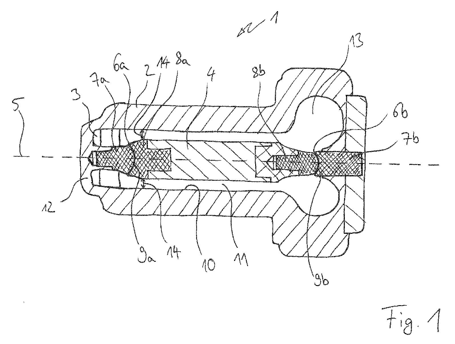
- Figure 1 shows a first embodiment of a fluid pump 1 according to the invention in a longitudinal sectional view.
- the fluid pump 1 is a rotating fluid pump which has a housing 2 which forms a stator of the rotating fluid pump 1.
- a rotor 4 is arranged within the housing 2 and rotates about an axis of rotation 5 running in the longitudinal direction of the fluid pump 1.
- the rotor 4 is mounted axially and radially in the housing 2 by means of a first mechanical bearing 6a and a second mechanical bearing 6b.
- the first mechanical bearing 6a has a first bearing element 7a and second bearing element 8a.
- the first bearing element 7a is rigidly connected to the housing 2 via struts 12, which are part of a cage geometry at the inlet of the fluid pump.
- the second bearing element 8a is rigidly connected to the rotor 4. In a contact area between the first bearing element 7a and the second bearing element 8a, the first 7a and the second bearing element 8a touch each other except for a bearing gap 9a.
- a part of the fluid conveyed by the fluid pump can be located in the bearing gap 9a and form a fluid film, so that the first and the second bearing elements 7a and 8a slide on one another in the contact area.
- the first mechanical bearing 6a is a ball-cup bearing, the first bearing element 7a having a convex spherical surface in the contact area and the second bearing element 8a having a concave spherical surface. It is also conceivable that the first bearing element 7a has a concave spherical surface and the second bearing element 8a has a convex spherical surface.
- the spherical contact area of the first mechanical bearing enables the rotor 4 to be supported both in the axial and in the radial direction.
- the second mechanical bearing 6b also has a first bearing element 7b and a second bearing element 8b, the first bearing element 7b being rigidly anchored in the housing 2 and the second bearing element 8b being rigidly connected to the rotor 4. Between the first bearing element 7b and the second bearing element 8b, the first 7b and the second bearing element 8b may touch each other except for a bearing gap 9b. Part of the fluid conveyed by the fluid pump can be located in the bearing gap and form a fluid film, so that the first and second bearing elements 7b and 8b slide over one another via the fluid film.
- the second mechanical bearing 6b is also designed as a ball-cup bearing with a spherical contact area, a surface of the first bearing element 7b being spherically concave in the contact region and a surface of the second bearing element 8b being spherically convex .
- the contact area of the second mechanical bearing also enables the rotor 4 to be supported both in the axial and in the radial direction.
- the fluid pump 1 has a fluid region 11 between the rotor 4 and an inner wall 10 of the housing 2 facing the rotor 4 which the fluid delivered by the fluid pump flows.
- the fluid to be conveyed reaches the fluid region 11 via a fluid inlet 3 of the fluid pump arranged in the region of the struts 12 and is transported away from the fluid inlet 3 by the rotational movement of the rotor 4 in the direction of the axis of rotation 5.
- the fluid area 11 is widened to form a volute 13.
- the essentially axial movement of the fluid changes into an essentially radial movement, the fluid then being ejected radially to the axis of rotation 5 from a fluid outlet (not shown here) arranged in the volute 13.
- the fluid region 11 has a flow cross section which changes in the direction of the axis of rotation.
- the flow cross-section has a reduction in the flow cross-section in the flow direction at the transition from the first bearing element 7a to the second bearing element 7b, the flow cross-section still reaching a flow cross-section minimum 14 in the area of the second bearing element 8a, which in the flow direction over the rest Length of the second bearing element 8a and a large part of the rotor length continues.
- the course of the flow cross-section in the region of the second bearing element 8a thus has a region-specific flow cross-section minimum 14.
- the reduction in the flow cross-section in the area of the second bearing element 8a is achieved by gradually increasing the circumference of the second bearing element 8a in the direction of flow, a wall diameter of the inner wall in the area of the first mechanical bearing 6a being constant along the axis of rotation 5.
- the maximum circumference of the second bearing element 8a is larger than the maximum circumference of the first bearing element 7a.
- Figure 2 shows a second embodiment of a fluid pump 1a according to the invention in a longitudinal sectional view.
- the fluid pump 1a is configured similarly to the fluid pump 1 of the first exemplary embodiment.
- the fluid pump 1a differs from the fluid pump 1 of the first exemplary embodiment essentially only in the design of the first mechanical bearing 6a.
- the first mechanical bearing 6a of the fluid pump 1a is also designed as a ball cup bearing, but the first bearing element 7a has a spherically concave surface in the contact region and the second bearing element 8a has a spherically convex surface, the first and second bearing elements 7a and 8a can slide on one another along their mutually facing surfaces via a fluid film located in the bearing gap 9a.
- the second bearing element 8a has a gradual increase in circumference in the flow direction beyond a maximum circumference of the first bearing element 7a, which leads to a reduction in the flow cross-section in the case of a constant wall diameter of the inner wall 10 in the region of the first mechanical bearing 6a. After reaching a maximum circumference, the circumference of the second bearing element 8a or of the immediately adjacent rotor body of the rotor 4 is reduced.
- the flow cross-section for the fluid to be conveyed by the fluid pump 1a thus has a local flow cross-sectional minimum in the region of the second bearing element 8a of the first mechanical bearing 6a 14, which is achieved by a local circumferential maximum of the second bearing element 8a.
- the local minimum flow cross section 14 enables the fluid above the first mechanical bearing 6a to be accelerated, as a result of which the latter can be washed out better and the frictional heat generated in the bearing 6a can be removed more quickly.
- Figure 3 shows a third embodiment of a fluid pump 1b according to the invention in a longitudinal sectional view.
- the fluid pump 1b is essentially designed like the fluid pump 1a of the second exemplary embodiment.
- the fluid pump 1b differs from the fluid pump 1a in that the inner wall 10 has a radial indentation in the region of the first mechanical bearing 6a.
- the wall diameter of the inner wall 10 along the axis of rotation 5 is not constant, but has a minimum in the area of the second bearing element 8a of the first mechanical bearing 6a. This minimum of the wall diameter is located at the point along the axis of rotation 5 at which the circumference of the second bearing element 8a has a local maximum.
- Figure 4 shows a fourth embodiment of a fluid pump 1c according to the invention in a longitudinal sectional view.
- the fluid pump 1c the Figure 4 is essentially like the fluid pump 1b Figure 3 educated.
- the fluid pump 1c the Figure 4 differs from the fluid pump 1b Figure 3 in the position and strength of the radial retraction of the inner wall 10 along the axis of rotation 5.
- the wall diameter is not locally reduced in the area of the second bearing element 8a, but in the area of the bearing gap 9a.
- the reduction is more pronounced than for the inner wall 10 of the fluid pump 1b.
- the fluid pump 1c thus has a local flow cross-sectional minimum 14 in the region of the bearing gap 9a of the first mechanical bearing 6a.
- Figures 5 to 12 show different variants of a flow cross-sectional profile according to the invention along the axis of rotation 5 in the region of the first mechanical bearing 6a in a schematic view.
- the inner wall 10 has a radial retraction at the axial height of the bearing gap 9a.
- the radial feed is symmetrical with respect to the bearing gap 9a.
- the bearing 6a itself has no widening.
- the circumferences of the first and second bearing elements 7a and 8a are essentially the same.
- Figure 5b shows the course of the actual flow cross section A along the axis of rotation (z).
- the local flow cross-sectional minimum 14 enables the fluid 15 to be accelerated in the region of the bearing 6a and thus improves washing out and cooling of the bearing.
- the particular advantage of this flow geometry is in that it is easy to implement, independent of direction and suitable for a short design, such as for small fluid pumps.
- Figure 6a shows a radial indentation of the inner wall 10 which is asymmetrical with respect to the bearing gap 9a, in which the flow cross-section decreases rapidly in the flow direction up to the bearing gap 9a and increases more slowly again after passing through the flow cross-section minimum 14.
- the minimum flow cross section is achieved solely by a radial retraction of the inner wall 10 without an expansion of the first mechanical bearing 6a.
- the advantage of this flow geometry is that the fluid flow is directed strongly inwards and is greatly accelerated above the bearing 6a. By slowly increasing the flow cross section after passing through the minimum, the risk of the fluid flow becoming detached is reduced.
- Figure 7 shows similar to in Figure 5 a symmetrical flow cross section minimum 14, which is again realized only by a radial retraction of the inner wall.
- the slopes upstream and downstream of the minimum flow cross section 14 are in Figure 7 however less than in Figure 5 , which results in a lower risk of the fluid flow becoming detached.
- This flow geometry is particularly suitable for larger fluid pumps.
- Figure 8 shows an area-specific flow cross-sectional minimum, which is realized by an area-wise radial indentation of the inner wall 10 on the heights of the bearing 6a.
- the draw-in reaches a maximum, so that the wall diameter remains constantly reduced from the bearing gap 9a to the rotor 4.
- the flow cross-sectional minimum 14 in some areas also extends approximately from the bearing gap 9a into the area of the rotor 4.
- the advantage of this flow geometry is the acceleration of the fluid flow over the bearing 6a and thus in the improved washing out and cooling of the bearing 6a and a low risk of the fluid flow becoming detached once the minimum flow cross section 14 has been reached.
- Figure 9 shows a symmetrical flow cross section minimum 14 in the area of the bearing gap 9a, which is realized only by a symmetrical expansion of the first and second bearing components 7a and 8a near the contact area or the bearing gap 9a.
- the inner wall 10 has no radial indentation and can have a constant wall diameter along the axis of rotation 5.
- the advantage of this flow geometry is in particular that the housing 2 (pump tube) is easy to manufacture. By selecting different slopes for the expansion of the bearing components, the fluid flow at the level of the bearing 6a and thus a washing out and cooling of the bearing area can be further optimized.
- Figure 10 exhibits a combination of the variants Figure 5 and Figure 9
- the symmetrical flow cross-sectional minimum 14 is realized both by a symmetrical expansion of the bearing components 7a and 8a and by a radial indentation of the inner wall 10 symmetrical about the bearing gap 9a.
- This combination enables a maximum reduction of the flow cross section in the area of the bearing 6a and thus a maximum acceleration of the fluid flow as well as improved washing out and cooling of the storage area.
- Figure 11 shows a region-specific flow cross-sectional minimum 14, which is realized solely by widening the bearing 6a.
- the first bearing element 7a is gradually widened to the bearing gap 9a. Downstream of the bearing gap 9a, the widening in the area of the second bearing element 8a reaches a maximum and remains at most up to the area of the rotor 4.
- the wall diameter of the inner wall 10 remains constant in the area of the bearing 6a.
- the flow cross-sectional minimum 14 begins in some areas downstream of the bearing gap 9a and extends along the axis of rotation 5 into the area of the rotor 4. This flow geometry also enables the fluid in the bearing area to be accelerated and thus improved washing and cooling of the bearing 6a.
- Figure 12 exhibits a combination of the variants Figure 5 and Figure 11 represents.
- Figure 12 shows an asymmetrical flow cross-sectional minimum 14 around the bearing gap 9a, which correspondingly by widening the bearing 6a in some areas Figure 11 and a symmetrical radial indentation of the inner Wall is realized at the bearing gap 9a.
- the flow cross-section drops sharply in the flow direction, while the flow cross-section downstream of the flow cross-section minimum increases more slowly to a smaller flow cross-section than before the reduction.
Landscapes
- Health & Medical Sciences (AREA)
- Engineering & Computer Science (AREA)
- Heart & Thoracic Surgery (AREA)
- Mechanical Engineering (AREA)
- Cardiology (AREA)
- Life Sciences & Earth Sciences (AREA)
- Public Health (AREA)
- Veterinary Medicine (AREA)
- General Health & Medical Sciences (AREA)
- Anesthesiology (AREA)
- Biomedical Technology (AREA)
- Hematology (AREA)
- Animal Behavior & Ethology (AREA)
- General Engineering & Computer Science (AREA)
- Physics & Mathematics (AREA)
- Fluid Mechanics (AREA)
- Vascular Medicine (AREA)
- Electromagnetism (AREA)
- Structures Of Non-Positive Displacement Pumps (AREA)
Abstract
Die vorliegende Erfindung betrifft Fluidpumpe zum Fördern eines Fluids, insbesondere von Blut, umfassend: ein Gehäuse mit einem Fluideinlass und einem Fluidauslass und einen Rotor, welcher innerhalb des Gehäuses zur Förderung des Fluids vom Fluideinlass zum Fluidauslass um eine Rotationsachse drehbar angeordnet ist, wobei der Rotor in dem Gehäuse mittels eines mechanischen Lagers gelagert ist. Die erfindungsgemäße Fluidpumpe zeichnet sich dadurch aus, dass ein Verlauf eines Strömungsquerschnitts zwischen dem Rotor und dem Gehäuse in Richtung der Rotationsachse im Bereich des mechanischen Lagers ein lokales oder bereichsweises Strömungsquerschnittsminimum aufweist.
Description
Die vorliegende Erfindung betrifft eine Fluidpumpe zum Fördern eines Fluids, insbesondere zum Fördern von Blut.The present invention relates to a fluid pump for delivering a fluid, in particular for delivering blood.
Ein bekanntes Problem von intrakorporalen Blutpumpen mit mechanischen Lagern ist eine unzureichende Lagerauswaschung und ein unzureichender Abtrag von im Lager entstehender Wärme, welche beispielsweise durch Reibung der Lagerelemente entsteht. Eine unzureichende Lagerauswaschung und ein unzureichender Wärmeabtrag in der Blutpumpe können das Risiko für eine Thrombenbildung und eine Blutgerinnung innerhalb der Blutpumpe erhöhen und damit eine Lebensgefahr für den Patienten darstellen.A known problem with intracorporeal blood pumps with mechanical bearings is inadequate bearing washout and inadequate removal of heat generated in the bearing, which arises, for example, from friction of the bearing elements. Inadequate bearing washout and inadequate heat dissipation in the blood pump can increase the risk of thrombus formation and blood clotting within the blood pump and thus pose a risk to life for the patient.
Eine Aufgabe der vorliegenden Erfindung ist es daher, eine Fluidpumpe bereitzustellen, welche eine verbesserte Lagerauswaschung und einen größeren Wärmeabtrag im Bereich des Lagers ermöglicht.It is therefore an object of the present invention to provide a fluid pump which enables improved bearing washout and greater heat removal in the area of the bearing.
Die Aufgabe wird durch eine Fluidpumpe gemäß Anspruch 1 gelöst. Vorteilhafte Weiterbildungen der erfindungsgemäßen Fluidpumpe sind in den abhängigen Ansprüchen 2 bis 13 aufgeführt.The object is achieved by a fluid pump according to claim 1. Advantageous developments of the fluid pump according to the invention are listed in the
Die erfindungsgemäße Fluidpumpe zum Fördern eines Fluids, insbesondere von Blut, umfasst ein Gehäuse mit einem Fluideinlass und einem Fluidauslass und einen Rotor, welcher innerhalb des Gehäuses zur Förderung des Fluids vom Fluideinlass zum Fluidauslass um eine Rotationsachse drehbar angeordnet ist. Der Rotor ist in dem Gehäuse mittels eines mechanischen Lagers gelagert. Die erfindungsgemäße Fluidpumpe zeichnet sich dadurch aus, dass ein Verlauf eines Strömungsquerschnitts zwischen dem Rotor und dem Gehäuse in Richtung der Rotationsachse im Bereich des mechanischen Lagers ein lokales oder bereichsweises Strömungsquerschnittsminimum aufweist.The fluid pump according to the invention for conveying a fluid, in particular blood, comprises a housing with a fluid inlet and a fluid outlet and a rotor which is arranged rotatably about an axis of rotation within the housing for conveying the fluid from the fluid inlet to the fluid outlet. The rotor is mounted in the housing by means of a mechanical bearing. The fluid pump according to the invention is characterized in that a course of a flow cross-section between the rotor and the housing in the direction of the axis of rotation in the area of the mechanical bearing has a local or area-specific flow cross-section minimum.
Unter dem Strömungsquerschnitt wird hier eine effektive Strömungsquerschnittsfläche innerhalb der Blutpumpe radial zur Rotationsachse verstanden, durch welche das geförderte Fluid zwischen dem Lager bzw. dem Rotor und dem Gehäuse hindurchfließt.The flow cross section is understood here to mean an effective flow cross-sectional area within the blood pump radially to the axis of rotation, through which the delivered fluid flows between the bearing or the rotor and the housing.
Weiterhin wird unter einem lokalen Strömungsquerschnittsminimum des Verlaufs des Strömungsquerschnitts in Richtung der Rotationsachse im Bereich des mechanischen Lagers eine lokale Verringerung des Strömungsquerschnitts bzw. der Strömungsquerschnittsfläche auf gleicher axialer Höhe wie das mechanische Lager, bezogen auf die Rotationsachse, verstanden.Furthermore, a local flow cross-sectional minimum of the course of the flow cross-section in the direction of the axis of rotation in the area of the mechanical bearing is understood to mean a local reduction in the flow cross-section or the flow cross-sectional area at the same axial height as the mechanical bearing, based on the axis of rotation.
Weiterhin wird unter einem bereichsweisen Strömungsquerschnittsminimum des Verlaufs des Strömungsquerschnitts in Richtung der Rotationsachse im Bereich des mechanischen Lagers eine Verringerung der Strömungsquerschnittsfläche verstanden, welche auf gleicher axialer Höhe wie das mechanische Lager, bezogen auf die Rotationsachse, einen Minimalwert erreicht und über einen bestimmten Bereich ihres Verlaufs in Richtung der Rotationsachse auf diesem Minimalwert bleibt.Furthermore, a region-by-region flow cross-sectional minimum of the course of the flow cross-section in the direction of the axis of rotation in the area of the mechanical bearing is understood to mean a reduction in the flow cross-sectional area, which at the same axial height as the mechanical bearing, relative to the axis of rotation, reaches a minimum value and over a specific area of its course remains at this minimum value in the direction of the axis of rotation.
Unter dem Bereich des mechanischen Lagers oder Lagerbereich wird im Wesentlichen ein Strömungsbereich des Fluids verstanden, welcher sich radial zum und entlang des ersten und zweiten Lagerelements, also radial zum und entlang des gesamten mechanischen Lagers erstreckt.The area of the mechanical bearing or bearing area is essentially understood to mean a flow area of the fluid which extends radially to and along the first and second bearing elements, that is to say radially to and along the entire mechanical bearing.
Im Folgenden bezieht sich die Formulierung "axiale Höhe" immer auf die Rotationsachse. Auf "gleicher axialer Höhe" bedeutet dabei auch "radial zu".In the following, the phrase "axial height" always refers to the axis of rotation. At "same axial height" also means "radial to".
Durch die Bildung eines Strömungsquerschnittsminimums im Bereich des mechanischen Lagers kann der geförderte Fluidstrom im Bereich des mechanischen Lagers beschleunigt werden. Durch die Beschleunigung des Fluidstroms wird das mechanische Lager besser ausgewaschen und im Lager entstehende Wärme, beispielsweise durch Reibung der Lagerelemente, kann schneller abtransportiert werden. Hierdurch verringert sich bei einer Blutpumpe das Risiko der Thrombenbildung und Blutgerinnung und somit eine Gefahr für den Patienten.The fluid flow delivered in the area of the mechanical bearing can be accelerated by the formation of a minimum flow cross section in the area of the mechanical bearing. By accelerating the fluid flow, the mechanical bearing is washed out better and heat generated in the bearing, for example due to friction of the bearing elements, can be removed more quickly. This reduces the risk of thrombus formation and blood clotting in a blood pump and thus a risk to the patient.
Ein größerer Wärmeabtrag kann ferner durch eine Erhöhung der Wandschubspannung und damit des Wärmeübergangs, durch eine verbesserte Durchmischung des Fluids im Bereich des Lagers oder durch eine verbesserte Ableitung der Wärme in den sich in der Fluidpumpe befindlichen Festkörpern durch eine Wahl von entsprechenden Materialien erreicht werden.A greater heat removal can also be achieved by increasing the wall shear stress and thus the heat transfer, by improving the mixing of the fluid in the area of the bearing or by improving the dissipation of the heat in the solids located in the fluid pump through a choice of appropriate materials.
Das mechanische Lager kann insbesondere eine erste mit dem Gehäuse verbundene Lagerkomponente und eine zweite mit dem Rotor verbundene Lagerkomponente aufweisen, wobei die erste und die zweite Lagerkomponente in Richtung der Rotationsachse in einem Kontaktbereich bis auf einen Lagerspalt aneinander anliegen, wobei sich das lokale oder bereichsweise Strömungsquerschnittsminimum im Bereich der ersten Lagerkomponente, insbesondere auf gleicher axialer Höhe wie die erste Lagerkomponente, im Bereich der zweiten Lagerkomponente, insbesondere auf gleicher axialer Höhe wie die zweite Lagerkomponente, und/oder im Bereich des Kontaktbereichs, insbesondere auf gleicher axialer Höhe wie der Kontaktbereich, befindet.The mechanical bearing can in particular have a first bearing component connected to the housing and a second bearing component connected to the rotor, the first and the second bearing components abutting against one another in a contact area in the direction of the axis of rotation except for a bearing gap, the local or area-specific minimum flow cross section in the area of the first bearing component, in particular at the same axial height as the first bearing component, in the area of the second bearing component, in particular at the same axial height as the second bearing component, and / or in the area of the contact area, in particular at the same axial height as the contact area .
Weiterhin kann das Gehäuse eine einen Fluidbereich begrenzende und in einer Umfangsrichtung um die Rotationsachse geschlossene innere Wandung aufweisen, und das lokale oder bereichsweise Strömungsquerschnittsminimum daraus resultieren, dass ein Verlauf eines Wandungsdurchmessers der inneren Wandung in Richtung der Rotationsachse im Bereich des mechanischen Lagers ein lokales oder bereichsweises Minimum aufweist.Furthermore, the housing can have an inner wall delimiting a fluid region and closed in a circumferential direction about the axis of rotation, and the local or regionally minimum flow cross section can result from the fact that a course of a wall diameter of the inner wall in the direction of the axis of rotation in the region of the mechanical bearing is local or regionally Minimum.
Insbesondere kann der Verlauf des Wandungsdurchmessers im Bereich der ersten Lagerkomponente, im Bereich der zweiten Lagerkomponente und/oder im Bereich des Kontaktbereichs ein lokales oder bereichsweises Minimum aufweisen.In particular, the profile of the wall diameter in the area of the first bearing component, in the area of the second bearing component and / or in the area of the contact area can have a local or area-specific minimum.
Weiterhin kann das lokale Strömungsquerschnittsminimum daraus resultieren, dass ein Verlauf eines Lagerdurchmessers des mechanischen Lagers in Richtung der Rotationsachse ein lokales oder bereichsweises Maximum aufweist. Insbesondere kann der Verlauf des Lagerdurchmessers im Bereich der ersten Lagerkomponente, im Bereich der zweiten Lagerkomponente und/oder im Bereich des Kontaktbereichs ein lokales oder bereichsweises Maximum aufweisen. Besonders vorteilhaft ist es, wenn die zweite Lagerkomponente einen größeren Durchmesser aufweist als die erste Lagerkomponente, die zweite Lagerkomponente also in Bezug auf die erste Lagerkomponente aufgeweitet ist.Furthermore, the local minimum flow cross section can result from the fact that a course of a bearing diameter of the mechanical bearing in the direction of the axis of rotation has a local or region-specific maximum. In particular, the course of the bearing diameter in the area of the first bearing component, in the area of the second bearing component and / or in the area of the contact area can have a local or area-by-area maximum. It is particularly advantageous if the second bearing component has a larger diameter than the first bearing component, that is to say the second bearing component is widened in relation to the first bearing component.
Der Strömungsquerschnitt kann im lokalen oder bereichsweisen Strömungsquerschnittsminimum um ≥ 10% und/oder ≤ 50%, insbesondere ≥ 20% und/oder ≤ 40%, vorzugsweise 30% verglichen mit einem Strömungsquerschnitt in einem dem Lagerbereich stromaufwärts und/oder stromabwärts benachbarten Bereich verringert sein.The flow cross section can be reduced in the local or area-wise minimum flow cross section by ≥ 10% and / or ≤ 50%, in particular ≥ 20% and / or ≤ 40%, preferably 30% compared to a flow cross section in an area upstream and / or downstream of the storage area .
Weiterhin kann die Fluidpumpe derart ausgebildet sein, dass sich der Strömungsquerschnitt in Richtung der Rotationsachse stromaufwärts des Strömungsquerschnittsminimums um ≥ 2 % des Strömungsquerschnittsminimums pro mm und/oder ≤ 30 % des Strömungsquerschnittsminimums pro mm und stromabwärts des Strömungsquerschnittsminimums um > 0 % des Strömungsquerschnittsminimums pro mm und/oder ≤ 20 % des Strömungsquerschnittsminimums pro mm, insbesondere ≤ 10 % des Strömungsquerschnittsminimums pro mm vergrößert. Unter der Vergrößerung des Strömungsquerschnitts stromaufwärts des Strömungsquerschnittsminimums wird eine Verkleinerung des Strömungsquerschnitts in Stromrichtung des Fluids vor dem und bis zum Strömungsquerschnittsminimum verstanden. Eine langsame oder nur geringe Vergrößerung des Strömungsquerschnitts stromabwärts, also in Strömungsrichtung des Fluids, weist ein geringeres Ablöse- und Verwirbelungsrisiko der Fluidströmung, also des stromabwärts strömenden Fluids, und damit im Falle von Blut ein geringeres Risiko einer Thrombenbildung in der Fluidpumpe auf. Eine schnellere oder stärkere Vergrößerung des Strömungsquerschnitts stromaufwärts stellt gleichzeitig eine schnellere oder stärkere Verkleinerung des Strömungsquerschnitts in Strömungsrichtung dar und ermöglicht so eine größere Beschleunigung des durch die Fluidpumpe strömenden Fluids, also eine größere Beschleunigung des Fluids stromabwärts, und somit eine schnellere Auswaschung und einen schnelleren Wärmeabtrag.Furthermore, the fluid pump can be designed such that the flow cross section in the direction of the axis of rotation upstream of the flow cross section minimum by ≥ 2% of the flow cross section minimum per mm and / or ≤ 30% of the flow cross section minimum per mm and downstream of the flow cross section minimum by> 0% of the flow cross section minimum per mm and / or ≤ 20% of the minimum flow cross section per mm, in particular ≤ 10% of the minimum flow cross section per mm. The enlargement of the flow cross-section upstream of the flow cross-section minimum is understood to mean a reduction in the flow cross-section in the flow direction of the fluid before and up to the flow cross-section minimum. A slow or only slight increase in the flow cross section downstream, that is to say in the direction of flow of the fluid, has a lower risk of detachment and swirling Fluid flow, that is to say the fluid flowing downstream, and thus in the case of blood there is a lower risk of thrombus formation in the fluid pump. A faster or stronger enlargement of the flow cross-section upstream simultaneously represents a faster or greater reduction in the flow cross-section in the flow direction and thus enables a greater acceleration of the fluid flowing through the fluid pump, i.e. a greater acceleration of the fluid downstream, and thus a faster washout and faster heat dissipation .
Ferner kann eine maximale Vergrößerung des Strömungsquerschnitts in Richtung der Rotationsachse stromaufwärts des lokalen oder bereichsweisen Strömungsquerschnittsminimums größer sein als oder gleich groß sein wie stromabwärts des lokalen oder bereichsweisen Strömungsquerschnittsminimums. Ist die Vergrößerung stromaufwärts und stromabwärts gleich groß, ist das Strömungsquerschnittsminimum symmetrisch. Ein derartiges Strömungsquerschnittsminimum kann durch ein symmetrisches Minimum des Wandungsdurchmessers und/oder durch ein symmetrisches Maximum des Lagerdurchmessers realisiert sein. Ein symmetrisches Strömungsquerschnittsminimum ist einfach und auch über einen kleinen Bereich des Verlaufs des Strömungsquerschnitts zu realisieren und damit insbesondere für kleine Fluidpumpen vorteilhaft. Ist die Vergrößerung stromaufwärts größer als stromabwärts kann der Fluidstrom zur schnelleren Auswaschung und Kühlung sowohl schnell beschleunigt als auch das Ablöserisiko des Fluidstroms minimiert werden.Furthermore, a maximum enlargement of the flow cross-section in the direction of the axis of rotation upstream of the local or region-specific flow cross-section minimum can be greater than or equal to that downstream of the local or region-specific flow cross-section minimum. If the magnification upstream and downstream is the same, the minimum flow cross section is symmetrical. Such a minimum flow cross section can be realized by a symmetrical minimum of the wall diameter and / or by a symmetrical maximum of the bearing diameter. A symmetrical flow cross-section minimum is simple and can also be implemented over a small area of the flow cross-section and is therefore particularly advantageous for small fluid pumps. If the magnification is greater upstream than downstream, the fluid flow can be quickly accelerated for faster washing out and cooling and the risk of the fluid flow becoming detached can be minimized.
Das lokale oder bereichsweise Strömungsquerschnittsminimum kann ein bereichsweises Strömungsquerschnittsminimum sein und sich vorzugsweise im Bereich des Kontaktbereichs sowie stromabwärts des Kontaktbereichs, insbesondere im Bereich des zweiten Lagerelements befinden. Ein derartiges bereichsweises Strömungsquerschnittsminimum weist ähnliche Vorteile auf, wie das oben beschriebene Strömungsquerschnittsminimum mit größerer Steigung stromaufwärts als stromabwärts, nämlich eine beschleunigte Auswaschung und Kühlung bei geringem Ablöserisiko des Fluidstroms.The local or partial flow cross-sectional minimum can be a partial flow cross-sectional minimum and is preferably located in the area of the contact area and downstream of the contact area, in particular in the area of the second bearing element. Such a region-wise flow cross-section minimum has similar advantages as the flow cross-section minimum described above with a larger gradient upstream than downstream, namely an accelerated washing out and cooling with a low risk of detachment of the fluid flow.
Das lokale oder bereichsweise Strömungsquerschnittsminimum kann insbesondere derart ausgebildet sein, dass eine Wandschubspannung im Bereich des mechanischen Lagers ein lokales Maximum aufweist oder maximal ist.The local or partial flow cross-sectional minimum can in particular be designed in such a way that a wall shear stress in the area of the mechanical bearing has a local maximum or is maximum.
Alternativ oder zusätzlich zur Ausbildung eines Strömungsquerschnittsminimums im Bereich des mechanischen Lagers und den vorstehend beschriebenen Ausführungsbeispielen kann eine Verbesserung des Wärmeabtrags auch durch Optimierung der Lagergeometrie, insbesondere der Geometrie der einzelnen Lagerkomponenten erreicht werden. Hierbei kann eine Oberfläche des Lagers vergrößert werden, insbesondere indem der Lagerdurchmesser erhöht wird, das Lager in Richtung der Rotationsachse länger gestaltet wird und/oder eine Oberfläche der ersten und zweiten Lagerkomponente eine sonstige oberflächenvergrößernde Geometrie aufweist. Insbesondere ist es vorteilhaft, wenn das Lager eine Länge von ≥ 3mm, insbesondere 5 bis 8 mm aufweist, um eine Verbesserung des Wärmeabtrags zu ermöglichen.As an alternative or in addition to the formation of a minimum flow cross section in the area of the mechanical bearing and the exemplary embodiments described above, an improvement in the heat removal can also be achieved by optimizing the bearing geometry, in particular the geometry of the individual bearing components. In this case, a surface of the bearing can be enlarged, in particular by increasing the bearing diameter, making the bearing longer in the direction of the axis of rotation and / or a surface of the first and second bearing components having a different surface-enlarging geometry. It is particularly advantageous if the bearing has a length of 3 3 mm, in particular 5 to 8 mm, in order to enable an improvement in the heat removal.
Alternativ oder zusätzlich zur Ausbildung eines Strömungsquerschnittsminimums im Bereich des mechanischen Lagers und den vorstehend beschriebenen Ausführungsbeispielen kann eine Verbesserung des Wärmeabtrags oder eine Verringerung der Wärmeentstehung durch Reibung zwischen den Lagerelementen auch durch eine Optimierung einer Materialauswahl für das mechanische Lager erreicht werden. Besonders vorteilhaft ist es, wenn das erste und/oder das zweite Lagerelement ein Material mit einem geringen Reibkoeffizienten und/oder mit einem hohen Wärmeleitungskoeffizienten, insbesondere Keramik, Sintermetall und/oder Diamant aufweist oder daraus besteht. Weiterhin kann das erste und/oder zweite Lagerelement mit einem Material mit geringem Reibkoeffizienten und/oder hohem Wärmeleitungskoeffizienten, insbesondere mit Keramik, Sintermetall und/oder Diamant beschichtet sein.As an alternative or in addition to the formation of a minimum flow cross section in the area of the mechanical bearing and the exemplary embodiments described above, an improvement in the heat removal or a reduction in the generation of heat by friction between the bearing elements can also be achieved by optimizing a selection of materials for the mechanical bearing. It is particularly advantageous if the first and / or the second bearing element has or consists of a material with a low coefficient of friction and / or with a high coefficient of thermal conductivity, in particular ceramic, sintered metal and / or diamond. Furthermore, the first and / or second bearing element can be coated with a material with a low coefficient of friction and / or high coefficient of thermal conductivity, in particular with ceramic, sintered metal and / or diamond.
Eine weitere Möglichkeit zur Optimierung der Auswaschung des Lagerbereichs des mechanischen Lagers besteht darin alternativ oder zusätzlich zur Ausbildung eines Strömungsquerschnittsminimums im Bereich des mechanischen Lagers und den vorstehend beschriebenen Ausführungsbeispielen stromaufwärts des mechanischen Lagers ein Vorlaufrad anzuordnen zur Erzeugung von entsprechend gerichteten Wirbeln in der Fluidströmung, welche die Auswaschung des mechanischen Lagers verbessern.Another possibility for optimizing the washing out of the bearing area of the mechanical bearing is, alternatively or in addition to the formation of a minimum flow cross section in the area of the mechanical bearing and the exemplary embodiments described above, to arrange a lead wheel upstream of the mechanical bearing in order to generate appropriately directed vortices in the fluid flow, which Improve washout of the mechanical bearing.
Weiterhin ist es denkbar zusätzlich oder alternativ zu den vorstehend beschriebenen Lösungen, das erste oder zweite Lagerelement mit Drehelementen oder Schaufeln am Rotor auszustatten, welche stromaufwärts über das mechanische Lager ragen. Diese Drehelemente können insbesondere zur Erzeugung von Wirbeln und Turbulenz im Lagerbereich ausgebildet sein, sodass eine Auswaschung und Kühlung des Lagerbereichs des mechanischen Lagers verbessert wird.Furthermore, it is conceivable in addition or as an alternative to the solutions described above, the first or second bearing element with rotating elements or to equip blades on the rotor which protrude upstream beyond the mechanical bearing. These rotary elements can in particular be designed to generate eddies and turbulence in the bearing area, so that washing out and cooling of the bearing area of the mechanical bearing is improved.
Weiterhin ist es denkbar zusätzlich oder alternativ zu den vorstehend beschriebenen Lösungen, stromaufwärts des mechanischen Lagers entsprechend ausgebildete und mit dem Gehäuse der Fluidpumpe verbundene Streben als Strömungselemente vorzusehen, welche die Fluidströmung und/oder die Wandschubspannung im Lagerbereich erhöhen und so eine Auswaschung des Lagerbereichs des mechanischen Lagers und einen Wärmeabtrag verbessern.Furthermore, in addition or as an alternative to the solutions described above, it is conceivable to provide, as upstream of the mechanical bearing, appropriately designed struts and flow elements connected to the housing of the fluid pump, which increase the fluid flow and / or the wall shear stress in the bearing area and thus wash out the bearing area of the mechanical Bearing and heat transfer improve.
Weiterhin ist es denkbar zusätzlich oder alternativ zu den vorstehend beschriebenen Lösungen den Rotor mit einer Unwucht auszustatten, welche derart ausgebildet ist, dass die Auswaschung im Bereich des mechanischen Lagers verbessert wird.Furthermore, it is conceivable, in addition or as an alternative to the solutions described above, to equip the rotor with an imbalance which is designed in such a way that the washout in the area of the mechanical bearing is improved.
Weiterhin ist es denkbar zusätzlich oder alternativ zu den vorstehend beschriebenen Lösungen eine Oberfläche des ersten und/oder zweiten Lagerelements mit einer Struktur oder Texturierung zu versehen, insbesondere eine Vielzahl von Vertiefungen zur Erzeugung eines Golfball-Effekts auf der Oberfläche des ersten und/oder zweiten Lagerelements anzuordnen. Hierdurch wird die Fluidströmung derart manipuliert, dass eine Lagerauswaschung und Kühlung des mechanischen Lagers verbessert wird.Furthermore, in addition or as an alternative to the solutions described above, it is conceivable to provide a surface of the first and / or second bearing element with a structure or texturing, in particular a multiplicity of depressions for producing a golf ball effect on the surface of the first and / or second bearing element to arrange. As a result, the fluid flow is manipulated in such a way that bearing washing and cooling of the mechanical bearing is improved.
Weiterhin ist es denkbar zusätzlich oder alternativ zu den vorstehend beschriebenen Lösungen stromaufwärts des mechanischen Lagers eine Geometrie anzuordnen, welche ausgebildet ist, Taylorwirbel zur Verbesserung der Lagerauswaschung und Kühlung sowie Erhöhung der Wandschubspannung im Bereich des mechanischen Lagers zu induzieren.Furthermore, in addition to or as an alternative to the solutions described above, it is conceivable to arrange a geometry upstream of the mechanical bearing which is designed to induce Taylor vortices to improve the bearing washout and cooling and to increase the wall shear stress in the area of the mechanical bearing.
Im Folgenden wird eine erfindungsgemäße Fluidpumpe anhand von Figuren detaillierter beschrieben. Dabei werden verschiedene erfindungswesentliche oder auch vorteilhafte weiterbildende Elemente im Rahmen jeweils eines konkreten Beispiels genannt, wobei auch einzelne dieser Elemente als solche zur Weiterbildung der Erfindung - auch herausgelöst aus dem Kontext des jeweiligen Beispiels und weiterer Merkmale des jeweiligen Beispiels - verwendet werden können. Weiterhin werden in den Figuren für gleiche oder ähnliche Elemente gleiche oder ähnliche Bezugszeichen verwendet, und deren Erläuterung daher teilweise weggelassen.A fluid pump according to the invention is described in more detail below with reference to figures. Various elements which are essential to the invention or are also advantageous are mentioned in the context of a specific example, individual elements of these as such for the further development of the invention - also detached from the context of respective example and further features of the respective example - can be used. Furthermore, the same or similar reference numerals are used in the figures for identical or similar elements, and their explanation is therefore partially omitted.
Es zeigen
- Figur 1
- eine schematische Längsschnittansicht einer erfindungsgemäßen Fluidpumpe gemäß einem ersten Ausführungsbeispiel,
Figur 2- eine schematische Längsschnittansicht einer erfindungsgemäßen Fluidpumpe gemäß einem zweiten Ausführungsbeispiel,
Figur 3- eine schematische Längsschnittansicht einer erfindungsgemäßen Fluidpumpe gemäß einem dritten Ausführungsbeispiel,
Figur 4- eine schematische Längsschnittansicht einer erfindungsgemäßen Fluidpumpe gemäß einem vierten Ausführungsbeispiel und
Figuren 5 bis 12- verschiedene Varianten möglicher Strömungsquerschnittsverläufe in schematischer Ansicht.
- Figure 1
- 2 shows a schematic longitudinal sectional view of a fluid pump according to the invention in accordance with a first exemplary embodiment,
- Figure 2
- 2 shows a schematic longitudinal sectional view of a fluid pump according to the invention in accordance with a second exemplary embodiment,
- Figure 3
- 2 shows a schematic longitudinal sectional view of a fluid pump according to the invention in accordance with a third exemplary embodiment,
- Figure 4
- is a schematic longitudinal sectional view of a fluid pump according to the invention according to a fourth embodiment and
- Figures 5 to 12
- Different variants of possible flow cross-sectional profiles in a schematic view.
Das erste mechanische Lager 6a weist ein erstes Lagerelement 7a und ein zweites Lagerelement 8a auf. Das erste Lagerelement 7a ist über Streben 12, welche Teil einer Käfiggeometrie am Einlass der Fluidpumpe sind, starr mit dem Gehäuse 2 verbunden. Das zweite Lagerelement 8a ist starr mit dem Rotor 4 verbunden. In einem Kontaktbereich zwischen dem ersten Lagerelement 7a und dem zweiten Lagerelement 8a berühren sich das erste 7a und das zweite Lagerelement 8a bis auf einen Lagerspalt 9a. In dem Lagerspalt 9a kann sich ein Teil des von der Fluidpumpe geförderten Fluids befinden und einen Fluidfilm ausbilden, sodass das erste und das zweite Lagerelement 7a und 8a in dem Kontaktbereich aufeinander gleiten. Bei dem ersten mechanischen Lager 6a handelt es sich um ein Ball-Cup-Lager, wobei im Kontaktbereich das erste Lagerelement 7a eine konvexe sphärische Oberfläche aufweist und das zweite Lagerelement 8a eine konkave sphärische Oberfläche aufweist. Ebenso ist es denkbar, dass das erste Lagerelement 7a eine konkave sphärische Oberfläche aufweist und das zweite Lagerelement 8a eine konvexe sphärische Oberfläche aufweist. Der so sphärisch ausgebildete Kontaktbereich des ersten mechanischen Lagers ermöglicht sowohl eine Lagerung des Rotors 4 in axialer als auch in radialer Richtung.The first mechanical bearing 6a has a
Das zweite mechanische Lager 6b weist ebenso ein erstes Lagerelement 7b und eine zweites Lagerelement 8b auf, wobei das erste Lagerelement 7b starr im Gehäuse 2 verankert ist und das zweite Lagerelement 8b starr mit dem Rotor 4 verbunden ist. Zwischen dem ersten Lagerelement 7b und dem zweiten Lagerelement 8b berühren sich das erste 7b und das zweite Lagerelement 8b gegebenenfalls bis auf einen Lagerspalt 9b. In dem Lagerspalt kann sich ein Teil des von der Fluidpumpe geförderten Fluids befinden und einen Fluidfilm ausbilden, sodass das erste und das zweite Lagerelement 7b und 8b über den Fluidfilm aufeinander gleiten. Wie das erste mechanische Lager 6a ist auch das zweite mechanische Lager 6b als Ball-Cup-Lager mit einem sphärischen Kontaktbereich ausgebildet, wobei in dem Kontaktbereich eine Oberfläche des ersten Lagerelements 7b sphärisch konkav ausgebildet ist und eine Oberfläche des zweiten Lagerelements 8b sphärisch konvex ausgebildet ist. Der Kontaktbereich des zweiten mechanischen Lagers ermöglicht ebenfalls eine Lagerung des Rotors 4 sowohl in axialer als auch in radialer Richtung.The second mechanical bearing 6b also has a first bearing element 7b and a second bearing element 8b, the first bearing element 7b being rigidly anchored in the
Die Fluidpumpe 1 weist einen Fluidbereich 11 zwischen dem Rotor 4 und einer dem Rotor 4 zugewandten inneren Wandung 10 des Gehäuses 2 auf, durch welchen das von der Fluidpumpe geförderte Fluid strömt. Das zu fördernde Fluid gelangt über einen im Bereich der Streben 12 angeordneten Fluideinlass 3 der Fluidpumpe in den Fluidbereich 11 und wird durch die Rotationsbewegung des Rotors 4 in Richtung der Rotationsachse 5 vom Fluideinlass 3 weg transportiert. Im Bereich des zweiten mechanischen Lagers 6b ist der Fluidbereich 11 zu einer Volute 13 verbreitert. In der Volute 13 geht die im Wesentlichen axiale Bewegung des Fluids in eine im Wesentlichen radiale Bewegung über, wobei das Fluid anschließend aus einem in der Volute 13 angeordneten Fluidauslass (hier nicht dargestellt) radial zur Rotationsachse 5 ausgestoßen wird.The fluid pump 1 has a
Der Fluidbereich 11 weist einen sich in Richtung der Rotationsachse verändernden Strömungsquerschnitt auf. Im Bereich des ersten mechanischen Lagers 6a weist der Strömungsquerschnitt beim Übergang vom ersten Lagerelement 7a zum zweiten Lagerelement 7b in Strömungsrichtung eine Verkleinerung des Strömungsquerschnitts auf, wobei der Strömungsquerschnitt noch im Bereich des zweiten Lagerelements 8a ein Strömungsquerschnittsminimum 14 erreicht, welches sich in Strömungsrichtung über die übrige Länge des zweiten Lagerelements 8a sowie einen Großteil der Rotorlänge fortsetzt. Somit weist der Verlauf des Strömungsquerschnitts im Bereich des zweiten Lagerelements 8a ein bereichsweises Strömungsquerschnittsminimum 14 auf. Die Verkleinerung des Strömungsquerschnitts im Bereich des zweiten Lagerelements 8a wird durch eine graduelle Vergrößerung des Umfangs des zweiten Lagerelements 8a in Strömungsrichtung erreicht, wobei ein Wandungsdurchmesser der inneren Wandung im Bereich des ersten mechanischen Lagers 6a entlang der Rotationsachse 5 konstant ist. Der maximale Umfang des zweiten Lagerelements 8a ist dabei größer als der maximale Umfang des ersten Lagerelements 7a. Die Verkleinerung des Strömungsquerschnitts im Bereich des zweiten Lagerelements 8a ermöglicht eine Beschleunigung des Fluids über dem ersten mechanischen Lager 6a, wodurch dieses besser ausgewaschen und im Lager 6a entstehende Reibungswärme schneller abtransportiert wird.The
In
Claims (13)
Priority Applications (5)
| Application Number | Priority Date | Filing Date | Title |
|---|---|---|---|
| EP19152910.6A EP3682918A1 (en) | 2019-01-21 | 2019-01-21 | Fluid pump |
| PCT/EP2020/051253 WO2020152086A1 (en) | 2019-01-21 | 2020-01-20 | Fluid pump |
| US17/420,362 US12485270B2 (en) | 2019-01-21 | 2020-01-20 | Fluid pump |
| CN202080009231.2A CN113301946A (en) | 2019-01-21 | 2020-01-20 | fluid pump |
| DE112020000458.9T DE112020000458A5 (en) | 2019-01-21 | 2020-01-20 | Fluid pump |
Applications Claiming Priority (1)
| Application Number | Priority Date | Filing Date | Title |
|---|---|---|---|
| EP19152910.6A EP3682918A1 (en) | 2019-01-21 | 2019-01-21 | Fluid pump |
Publications (1)
| Publication Number | Publication Date |
|---|---|
| EP3682918A1 true EP3682918A1 (en) | 2020-07-22 |
Family
ID=65138942
Family Applications (1)
| Application Number | Title | Priority Date | Filing Date |
|---|---|---|---|
| EP19152910.6A Withdrawn EP3682918A1 (en) | 2019-01-21 | 2019-01-21 | Fluid pump |
Country Status (5)
| Country | Link |
|---|---|
| US (1) | US12485270B2 (en) |
| EP (1) | EP3682918A1 (en) |
| CN (1) | CN113301946A (en) |
| DE (1) | DE112020000458A5 (en) |
| WO (1) | WO2020152086A1 (en) |
Citations (4)
| Publication number | Priority date | Publication date | Assignee | Title |
|---|---|---|---|---|
| WO1996018358A1 (en) * | 1994-12-16 | 1996-06-20 | Robert Jarvik | High reliability cardiac assist system |
| US5957672A (en) * | 1993-11-10 | 1999-09-28 | The United States Of America As Represented By The Administrator Of The National Aeronautics And Space Administration | Blood pump bearing system |
| WO2003075981A1 (en) * | 2002-03-08 | 2003-09-18 | Cardianove Inc. | Dual inlet mixed-flow blood pump |
| WO2016086137A1 (en) * | 2014-11-26 | 2016-06-02 | Thoratec Corporation | Pump and method for mixed flow blood pumping |
Family Cites Families (3)
| Publication number | Priority date | Publication date | Assignee | Title |
|---|---|---|---|---|
| EP0653022B1 (en) * | 1992-07-30 | 2001-12-05 | Cobe Cardiovascular, Inc. | Centrifugal blood pump |
| DE102006036948A1 (en) * | 2006-08-06 | 2008-02-07 | Akdis, Mustafa, Dipl.-Ing. | blood pump |
| DK3821938T3 (en) * | 2015-03-18 | 2024-08-19 | Abiomed Europe Gmbh | BLOOD PUMP |
-
2019
- 2019-01-21 EP EP19152910.6A patent/EP3682918A1/en not_active Withdrawn
-
2020
- 2020-01-20 WO PCT/EP2020/051253 patent/WO2020152086A1/en not_active Ceased
- 2020-01-20 DE DE112020000458.9T patent/DE112020000458A5/en not_active Withdrawn
- 2020-01-20 CN CN202080009231.2A patent/CN113301946A/en not_active Withdrawn
- 2020-01-20 US US17/420,362 patent/US12485270B2/en active Active
Patent Citations (4)
| Publication number | Priority date | Publication date | Assignee | Title |
|---|---|---|---|---|
| US5957672A (en) * | 1993-11-10 | 1999-09-28 | The United States Of America As Represented By The Administrator Of The National Aeronautics And Space Administration | Blood pump bearing system |
| WO1996018358A1 (en) * | 1994-12-16 | 1996-06-20 | Robert Jarvik | High reliability cardiac assist system |
| WO2003075981A1 (en) * | 2002-03-08 | 2003-09-18 | Cardianove Inc. | Dual inlet mixed-flow blood pump |
| WO2016086137A1 (en) * | 2014-11-26 | 2016-06-02 | Thoratec Corporation | Pump and method for mixed flow blood pumping |
Also Published As
| Publication number | Publication date |
|---|---|
| US20220088370A1 (en) | 2022-03-24 |
| DE112020000458A5 (en) | 2021-09-30 |
| CN113301946A (en) | 2021-08-24 |
| WO2020152086A1 (en) | 2020-07-30 |
| US12485270B2 (en) | 2025-12-02 |
Similar Documents
| Publication | Publication Date | Title |
|---|---|---|
| DE69733612T2 (en) | WATER TURBINE | |
| EP2297430B1 (en) | Axial turbine for a gas turbine | |
| DE69711793T2 (en) | Blade for axial fluid machine | |
| DE4006604C2 (en) | ||
| DE20317497U1 (en) | Plain thrust bearing for bearings in an exhaust gas turbocharger's rotating shaft linked to a lubricating oil circuit, has a sliding surface and a bearing surface with lubricating gap | |
| WO2009144102A1 (en) | Collecting chamber and production method | |
| EP3300750A1 (en) | Blood pump | |
| WO2011054812A2 (en) | Turbomachine with axial compression or expansion | |
| EP1292760B1 (en) | Configuration of a coolable turbine blade | |
| DE202018107062U1 (en) | Radial shaft sealing device | |
| EP3473808B1 (en) | Blade for an internally cooled turbine blade and method for producing same | |
| WO2018011427A1 (en) | Swirler and cone nozzle with such a swirler | |
| WO2014044363A1 (en) | Bearing device and turbocharger | |
| EP3181813B1 (en) | Center-of-gravity threading of rotor blades | |
| EP3682918A1 (en) | Fluid pump | |
| EP3268616B1 (en) | Self-priming pump | |
| EP2963243B1 (en) | Flow engine with blades having blade tips lowering towards the trailing edge | |
| DE3309454A1 (en) | METHOD FOR PRODUCING A TURBINE HOUSING | |
| EP3704386A1 (en) | Additively manufactured intermediate channel for arranging between a low-pressure compressor and a high-pressure compressor, and corresponding manufacturing method | |
| EP1798376B1 (en) | Method for manufacturing of a secondary flow channel | |
| DE102012001989B4 (en) | Method for mechanical edge zone consolidation of components | |
| DE112019001424B4 (en) | Bearing bushing for a turbocharger shaft | |
| AT525670B1 (en) | Blade of a Pelton turbine | |
| CH577108A5 (en) | Turbine blade concave/convex profiles - have constant thickness to certain point whence material thicknes to foot | |
| WO1995032804A1 (en) | Rotary nozzle for high pressure cleaning appliances |
Legal Events
| Date | Code | Title | Description |
|---|---|---|---|
| PUAI | Public reference made under article 153(3) epc to a published international application that has entered the european phase |
Free format text: ORIGINAL CODE: 0009012 |
|
| STAA | Information on the status of an ep patent application or granted ep patent |
Free format text: STATUS: THE APPLICATION HAS BEEN PUBLISHED |
|
| AK | Designated contracting states |
Kind code of ref document: A1 Designated state(s): AL AT BE BG CH CY CZ DE DK EE ES FI FR GB GR HR HU IE IS IT LI LT LU LV MC MK MT NL NO PL PT RO RS SE SI SK SM TR |
|
| AX | Request for extension of the european patent |
Extension state: BA ME |
|
| STAA | Information on the status of an ep patent application or granted ep patent |
Free format text: STATUS: THE APPLICATION IS DEEMED TO BE WITHDRAWN |
|
| 18D | Application deemed to be withdrawn |
Effective date: 20210123 |