EP3665528B1 - Electro-optical device having a transparent ion exchange membrane - Google Patents
Electro-optical device having a transparent ion exchange membrane Download PDFInfo
- Publication number
- EP3665528B1 EP3665528B1 EP18844524.1A EP18844524A EP3665528B1 EP 3665528 B1 EP3665528 B1 EP 3665528B1 EP 18844524 A EP18844524 A EP 18844524A EP 3665528 B1 EP3665528 B1 EP 3665528B1
- Authority
- EP
- European Patent Office
- Prior art keywords
- individually
- alkylene
- alkyl
- aryl
- heterocycloalkylene
- Prior art date
- Legal status (The legal status is an assumption and is not a legal conclusion. Google has not performed a legal analysis and makes no representation as to the accuracy of the status listed.)
- Active
Links
Images


Classifications
-
- C—CHEMISTRY; METALLURGY
- C08—ORGANIC MACROMOLECULAR COMPOUNDS; THEIR PREPARATION OR CHEMICAL WORKING-UP; COMPOSITIONS BASED THEREON
- C08J—WORKING-UP; GENERAL PROCESSES OF COMPOUNDING; AFTER-TREATMENT NOT COVERED BY SUBCLASSES C08B, C08C, C08F, C08G or C08H
- C08J5/00—Manufacture of articles or shaped materials containing macromolecular substances
- C08J5/20—Manufacture of shaped structures of ion-exchange resins
- C08J5/22—Films, membranes or diaphragms
- C08J5/2206—Films, membranes or diaphragms based on organic and/or inorganic macromolecular compounds
- C08J5/2218—Synthetic macromolecular compounds
- C08J5/2256—Synthetic macromolecular compounds based on macromolecular compounds obtained by reactions other than those involving carbon-to-carbon bonds, e.g. obtained by polycondensation
-
- C—CHEMISTRY; METALLURGY
- C08—ORGANIC MACROMOLECULAR COMPOUNDS; THEIR PREPARATION OR CHEMICAL WORKING-UP; COMPOSITIONS BASED THEREON
- C08G—MACROMOLECULAR COMPOUNDS OBTAINED OTHERWISE THAN BY REACTIONS ONLY INVOLVING UNSATURATED CARBON-TO-CARBON BONDS
- C08G65/00—Macromolecular compounds obtained by reactions forming an ether link in the main chain of the macromolecule
-
- C—CHEMISTRY; METALLURGY
- C08—ORGANIC MACROMOLECULAR COMPOUNDS; THEIR PREPARATION OR CHEMICAL WORKING-UP; COMPOSITIONS BASED THEREON
- C08F—MACROMOLECULAR COMPOUNDS OBTAINED BY REACTIONS ONLY INVOLVING CARBON-TO-CARBON UNSATURATED BONDS
- C08F216/00—Copolymers of compounds having one or more unsaturated aliphatic radicals, each having only one carbon-to-carbon double bond, and at least one being terminated by an alcohol, ether, aldehydo, ketonic, acetal or ketal radical
- C08F216/02—Copolymers of compounds having one or more unsaturated aliphatic radicals, each having only one carbon-to-carbon double bond, and at least one being terminated by an alcohol, ether, aldehydo, ketonic, acetal or ketal radical by an alcohol radical
- C08F216/04—Acyclic compounds
- C08F216/06—Polyvinyl alcohol ; Vinyl alcohol
-
- C—CHEMISTRY; METALLURGY
- C08—ORGANIC MACROMOLECULAR COMPOUNDS; THEIR PREPARATION OR CHEMICAL WORKING-UP; COMPOSITIONS BASED THEREON
- C08F—MACROMOLECULAR COMPOUNDS OBTAINED BY REACTIONS ONLY INVOLVING CARBON-TO-CARBON UNSATURATED BONDS
- C08F216/00—Copolymers of compounds having one or more unsaturated aliphatic radicals, each having only one carbon-to-carbon double bond, and at least one being terminated by an alcohol, ether, aldehydo, ketonic, acetal or ketal radical
- C08F216/38—Copolymers of compounds having one or more unsaturated aliphatic radicals, each having only one carbon-to-carbon double bond, and at least one being terminated by an alcohol, ether, aldehydo, ketonic, acetal or ketal radical by an acetal or ketal radical
-
- C—CHEMISTRY; METALLURGY
- C08—ORGANIC MACROMOLECULAR COMPOUNDS; THEIR PREPARATION OR CHEMICAL WORKING-UP; COMPOSITIONS BASED THEREON
- C08G—MACROMOLECULAR COMPOUNDS OBTAINED OTHERWISE THAN BY REACTIONS ONLY INVOLVING UNSATURATED CARBON-TO-CARBON BONDS
- C08G61/00—Macromolecular compounds obtained by reactions forming a carbon-to-carbon link in the main chain of the macromolecule
- C08G61/12—Macromolecular compounds containing atoms other than carbon in the main chain of the macromolecule
- C08G61/122—Macromolecular compounds containing atoms other than carbon in the main chain of the macromolecule derived from five- or six-membered heterocyclic compounds, other than imides
- C08G61/123—Macromolecular compounds containing atoms other than carbon in the main chain of the macromolecule derived from five- or six-membered heterocyclic compounds, other than imides derived from five-membered heterocyclic compounds
- C08G61/125—Macromolecular compounds containing atoms other than carbon in the main chain of the macromolecule derived from five- or six-membered heterocyclic compounds, other than imides derived from five-membered heterocyclic compounds with a five-membered ring containing one oxygen atom in the ring
-
- C—CHEMISTRY; METALLURGY
- C08—ORGANIC MACROMOLECULAR COMPOUNDS; THEIR PREPARATION OR CHEMICAL WORKING-UP; COMPOSITIONS BASED THEREON
- C08J—WORKING-UP; GENERAL PROCESSES OF COMPOUNDING; AFTER-TREATMENT NOT COVERED BY SUBCLASSES C08B, C08C, C08F, C08G or C08H
- C08J5/00—Manufacture of articles or shaped materials containing macromolecular substances
- C08J5/20—Manufacture of shaped structures of ion-exchange resins
- C08J5/22—Films, membranes or diaphragms
- C08J5/2206—Films, membranes or diaphragms based on organic and/or inorganic macromolecular compounds
- C08J5/2218—Synthetic macromolecular compounds
- C08J5/2231—Synthetic macromolecular compounds based on macromolecular compounds obtained by reactions involving unsaturated carbon-to-carbon bonds
- C08J5/2243—Synthetic macromolecular compounds based on macromolecular compounds obtained by reactions involving unsaturated carbon-to-carbon bonds obtained by introduction of active groups capable of ion-exchange into compounds of the type C08J5/2231
-
- G—PHYSICS
- G02—OPTICS
- G02F—OPTICAL DEVICES OR ARRANGEMENTS FOR THE CONTROL OF LIGHT BY MODIFICATION OF THE OPTICAL PROPERTIES OF THE MEDIA OF THE ELEMENTS INVOLVED THEREIN; NON-LINEAR OPTICS; FREQUENCY-CHANGING OF LIGHT; OPTICAL LOGIC ELEMENTS; OPTICAL ANALOGUE/DIGITAL CONVERTERS
- G02F1/00—Devices or arrangements for the control of the intensity, colour, phase, polarisation or direction of light arriving from an independent light source, e.g. switching, gating or modulating; Non-linear optics
- G02F1/01—Devices or arrangements for the control of the intensity, colour, phase, polarisation or direction of light arriving from an independent light source, e.g. switching, gating or modulating; Non-linear optics for the control of the intensity, phase, polarisation or colour
- G02F1/15—Devices or arrangements for the control of the intensity, colour, phase, polarisation or direction of light arriving from an independent light source, e.g. switching, gating or modulating; Non-linear optics for the control of the intensity, phase, polarisation or colour based on an electrochromic effect
- G02F1/1503—Devices or arrangements for the control of the intensity, colour, phase, polarisation or direction of light arriving from an independent light source, e.g. switching, gating or modulating; Non-linear optics for the control of the intensity, phase, polarisation or colour based on an electrochromic effect caused by oxidation-reduction reactions in organic liquid solutions, e.g. viologen solutions
-
- C—CHEMISTRY; METALLURGY
- C08—ORGANIC MACROMOLECULAR COMPOUNDS; THEIR PREPARATION OR CHEMICAL WORKING-UP; COMPOSITIONS BASED THEREON
- C08J—WORKING-UP; GENERAL PROCESSES OF COMPOUNDING; AFTER-TREATMENT NOT COVERED BY SUBCLASSES C08B, C08C, C08F, C08G or C08H
- C08J2329/00—Characterised by the use of homopolymers or copolymers of compounds having one or more unsaturated aliphatic radicals, each having only one carbon-to-carbon double bond, and at least one being terminated by an alcohol, ether, aldehydo, ketonic, acetal, or ketal radical; Hydrolysed polymers of esters of unsaturated alcohols with saturated carboxylic acids; Derivatives of such polymer
- C08J2329/14—Homopolymers or copolymers of acetals or ketals obtained by polymerisation of unsaturated acetals or ketals or by after-treatment of polymers of unsaturated alcohols
-
- C—CHEMISTRY; METALLURGY
- C08—ORGANIC MACROMOLECULAR COMPOUNDS; THEIR PREPARATION OR CHEMICAL WORKING-UP; COMPOSITIONS BASED THEREON
- C08J—WORKING-UP; GENERAL PROCESSES OF COMPOUNDING; AFTER-TREATMENT NOT COVERED BY SUBCLASSES C08B, C08C, C08F, C08G or C08H
- C08J2363/00—Characterised by the use of epoxy resins; Derivatives of epoxy resins
-
- C—CHEMISTRY; METALLURGY
- C08—ORGANIC MACROMOLECULAR COMPOUNDS; THEIR PREPARATION OR CHEMICAL WORKING-UP; COMPOSITIONS BASED THEREON
- C08J—WORKING-UP; GENERAL PROCESSES OF COMPOUNDING; AFTER-TREATMENT NOT COVERED BY SUBCLASSES C08B, C08C, C08F, C08G or C08H
- C08J2371/00—Characterised by the use of polyethers obtained by reactions forming an ether link in the main chain; Derivatives of such polymers
- C08J2371/02—Polyalkylene oxides
- C08J2371/03—Polyepihalohydrins
-
- G—PHYSICS
- G02—OPTICS
- G02F—OPTICAL DEVICES OR ARRANGEMENTS FOR THE CONTROL OF LIGHT BY MODIFICATION OF THE OPTICAL PROPERTIES OF THE MEDIA OF THE ELEMENTS INVOLVED THEREIN; NON-LINEAR OPTICS; FREQUENCY-CHANGING OF LIGHT; OPTICAL LOGIC ELEMENTS; OPTICAL ANALOGUE/DIGITAL CONVERTERS
- G02F1/00—Devices or arrangements for the control of the intensity, colour, phase, polarisation or direction of light arriving from an independent light source, e.g. switching, gating or modulating; Non-linear optics
- G02F1/01—Devices or arrangements for the control of the intensity, colour, phase, polarisation or direction of light arriving from an independent light source, e.g. switching, gating or modulating; Non-linear optics for the control of the intensity, phase, polarisation or colour
- G02F1/15—Devices or arrangements for the control of the intensity, colour, phase, polarisation or direction of light arriving from an independent light source, e.g. switching, gating or modulating; Non-linear optics for the control of the intensity, phase, polarisation or colour based on an electrochromic effect
- G02F2001/164—Devices or arrangements for the control of the intensity, colour, phase, polarisation or direction of light arriving from an independent light source, e.g. switching, gating or modulating; Non-linear optics for the control of the intensity, phase, polarisation or colour based on an electrochromic effect the electrolyte is made of polymers
Definitions
- the present technology is generally related to electrooptical devices. More particularly, it is related to electrochromic devices having a persistent color memory for a substantial time period once being charged and after voltage removed.
- the present technology is also related to polymeric materials and ion exchange or ion selective membranes.
- WO 2016/145120 A1 describes an electrochromic device including a first flexible or rigid plastic substrate including a front surface, and a rear surface, wherein the rear surface comprises a first conductive material; and the front surface, the rear surface, or both the front surface and the rear surface of the first substrate comprises a gas diffusion barrier; and a second flexible or rigid plastic substrate including a front surface, and a rear surface, wherein the front surface comprises a second conductive material, wherein the first substrate is joined to the second substrate by a sealing member, where the rear surface of the first substrate and the front surface of the second substrate with the sealing member define a chamber therebetween.
- US 2015/076390 A1 describes an electrochromic device including a first substantially transparent substrate having an electrically conductive material associated therewith; a second substrate having an electrically conductive material associated therewith; and an electrochromic medium contained within a chamber positioned between the first and second substrates which includes: at least one solvent; at least one anodic electroactive material; at least one cathodic electroactive material; wherein at least one of the anodic and cathodic electroactive materials is electrochromic; and a creep resistant crosslinked polyelectrolyte gel matrix.
- US 2014/138589 A1 describes a composition containing a nano-carbon material, such as a carbon nanotube, and a polyether-based polymer containing oxirane monomer units at least part of which are oxirane monomer units each having a cationic group.
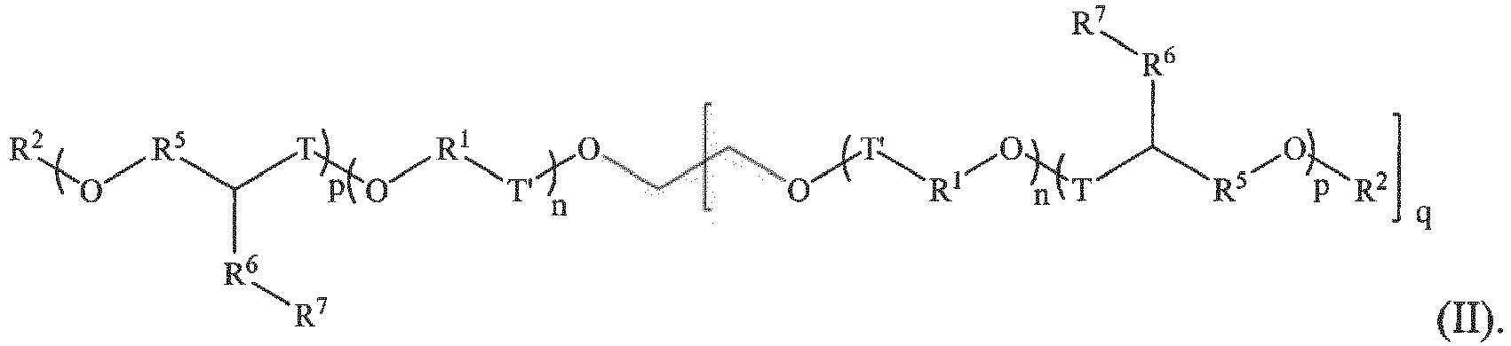
- a cationic polymer is provided as represented by Formula I or Formula II: and In the above formulae:
- each R 1 may be individually C 1 -C 6 alkylene, C 3 -C 16 cycloalkylene, or C 3 -C 16 heterocycloalkylene
- R 2 may be H
- each R 3 may be individually C 1 -C 6 alkyl, C 3 -C 16 cycloalkyl, or C 3 -C 16 heterocycloalkyl
- each R 4 maybe individually C 1 -C 6 alkylene, C 3 -C 16 cycloalkylene, or C 3 -C 16 heterocycloalkylene
- each R 5 may be individually absent or C 1 -C 6 alkylene, C 3 -C 16 cycloalkylene, or C 3 -C 16 heterocycloalkylene
- each X - may be individually an anion
- q is 2.
- R 6 may be -CH 2 -.
- an electrochromic device in another aspect, includes a cathodic compartment including a cathodic material; an anodic compartment including an anodic material; and a transparent, ion-selective membrane displaced between the cathodic compartment and the anodic compartment; wherein the transparent, ion-selective membrane includes a cationic polymer.
- the cationic polymer includes ammonium, phosphonium, pyridinium, or imidazolium functionality; and an oxygenated backbone.
- the electrochromic devices includes any of the cationic polymers described herein by any one or more of Formula I or Formula II.
- the transparent, ion-selective membrane comprises an anionic polymer and one or both the cathodic and anodic materials are anions in the activated state.
- the transparent, ion-selective membrane comprises a cationic polymer and one or both the cathodic and anodic materials are cations in the activated state.
- substituted refers to an alkyl, alkenyl, alkynyl, aryl, or ether group, as defined below (e.g., an alkyl group) in which one or more bonds to a hydrogen atom contained therein are replaced by a bond to non-hydrogen or non-carbon atoms.
- Substituted groups also include groups in which one or more bonds to a carbon(s) or hydrogen(s) atom are replaced by one or more bonds, including double or triple bonds, to a heteroatom.
- a substituted group will be substituted with one or more substituents, unless otherwise specified.
- a substituted group is substituted with 1, 2, 3, 4, 5, or 6 substituents.
- substituent groups include: halogens (i.e., F, Cl, Br, and I); hydroxyls; alkoxy, alkenoxy, alkynoxy, aryloxy, aralkyloxy, heterocyclyloxy, and heterocyclylalkoxy groups; carbonyls (oxo); carboxyls; esters; urethanes; oximes; hydroxylamines; alkoxyamines; aralkoxyamines; thiols; sulfides; sulfoxides; sulfones; sulfonyls; sulfonamides; amines; N-oxides; hydrazines; hydrazides; hydrazones; azides; amides; ureas; amidines; guanidines; enamines; imides; isocyanates; isothiocyanates; cyanates; thiocyanates; imines; nitro groups; nitriles (i.
- alkyl groups include straight chain and branched alkyl groups having from 1 to about 20 carbon atoms, and typically from 1 to 12 carbons or, in some embodiments, from 1 to 8 carbon atoms.
- alkyl groups include cycloalkyl groups as defined below. Alkyl groups may be substituted or unsubstituted. Examples of straight chain alkyl groups include methyl, ethyl, n-propyl, n-butyl, n-pentyl, n-hexyl, n-heptyl, and n-octyl groups.
- branched alkyl groups include, but are not limited to, isopropyl, sec-butyl, t-butyl, neopentyl, and isopentyl groups.
- Representative substituted alkyl groups may be substituted one or more times with, for example, amino, thio, hydroxy, cyano, alkoxy, and/or halo groups such as F, Cl, Br, and I groups.
- haloalkyl is an alkyl group having one or more halo groups. In some embodiments, haloalkyl refers to a per-haloalkyl group.
- Cycloalkyl groups are cyclic alkyl groups such as, but not limited to, cyclopropyl, cyclobutyl, cyclopentyl, cyclohexyl, cycloheptyl, and cyclooctyl groups.
- the cycloalkyl group has 3 to 8 ring members, whereas in other embodiments the number of ring carbon atoms range from 3 to 5, 6, or 7. Cycloalkyl groups may be substituted or unsubstituted.
- Cycloalkyl groups further include polycyclic cycloalkyl groups such as, but not limited to, norbornyl, adamantyl, bornyl, camphenyl, isocamphenyl, and carenyl groups, and fused rings such as, but not limited to, decalinyl, and the like. Cycloalkyl groups also include rings that are substituted with straight or branched chain alkyl groups as defined above.
- Representative substituted cycloalkyl groups may be mono-substituted or substituted more than once, such as, but not limited to: 2,2-; 2,3-; 2,4-; 2,5-; or 2,6-disubstituted cyclohexyl groups or mono-, di-, or tri-substituted norbornyl or cycloheptyl groups, which may be substituted with, for example, alkyl, alkoxy, amino, thio, hydroxy, cyano, and/or halo groups.
- Alkenyl groups are straight chain, branched or cyclic alkyl groups having 2 to about 20 carbon atoms, and further including at least one double bond. In some embodiments alkenyl groups have from 2 to 12 carbons, or, typically, from 2 to 8 carbon atoms. Alkenyl groups may be substituted or unsubstituted. Alkenyl groups include, for instance, vinyl, propenyl, 2-butenyl, 3-butenyl, isobutenyl, cyclohexenyl, cyclopentenyl, cyclohexadienyl, butadienyl, pentadienyl, and hexadienyl groups among others.
- Alkenyl groups may be substituted similarly to alkyl groups.
- aryl or “aromatic,” groups are cyclic aromatic hydrocarbons that do not contain heteroatoms.
- Aryl groups include monocyclic, bicyclic and polycyclic ring systems.
- aryl groups include, but are not limited to, phenyl, azulenyl, heptalenyl, biphenylenyl, indacenyl, fluorenyl, phenanthrenyl, triphenylenyl, pyrenyl, naphthacenyl, chrysenyl, biphenyl, anthracenyl, indenyl, indanyl, pentalenyl, and naphthyl groups.
- aryl groups contain 6-14 carbons, and in others from 6 to 12 or even 6-10 carbon atoms in the ring portions of the groups.
- aryl groups includes groups containing fused rings, such as fused aromatic-aliphatic ring systems (e.g., indanyl, tetrahydronaphthyl, and the like).
- Aryl groups may be substituted or unsubstituted.
- reference to any group e.g., alkyl, aryl, heteroaryl, heterocyclyl, cyclyl, alkenyl, alkynyl, etc., includes reference to both substituted and unsubstituted such groups.
- solution-based electrochromic devices are very stable to chemical durability testing (weathering).
- one disadvantage, at least for some applications, for a single-compartment, self-erasing, solution-based electrochromic device is that constant power is needed to be applied to a device in order for it to remain in the darken state. The constant power consumption makes some applications difficult or prohibitive.
- a multi-compartment device that is able to maintain a darkened, or low-transmission state, at open circuit.
- the multi-compartment devices include a cathodic compartment and an anodic compartment, with a separator layer therebetween. Additionally, the separator layer includes a colorless, or at least nearly colorless, transparent, chemically stable, ion exchange membrane.
- Such membranes allow for the free diffusion of an electrolyte of a particular charge through the membrane, but prohibit (or at least significantly impede) the free passage of the opposite charge.
- the membrane is a cationic membrane, it will allow for passage of anions while excluding cations, and vice versa.
- passage of one charged type of ion is allowed while impeding the passage of the opposite charged ion.
- the anodic and cathodic redox active materials should be soluble ionic compounds of the same charge (i.e., negative or positive), while in the electrochemically active and/or darkened state and the membrane separating the redox active media should only allow passage of the opposite charge, either from a supporting electrolyte or the counter-ion associated with the electrochromic material(s).
- the ion exchange membrane should be an anion exchange membrane.
- the ion exchange membrane should be a cation exchange membrane.
- the electrolyte of the opposite charge to the membrane may be either from a supporting electrolyte and/or the counter-ion from either redox electroactive anodic or cathodic material.
- an electrochromic device in one aspect, includes a cathodic compartment, an anodic compartment, and a transparent, ion-selective membrane displaced between the cathodic compartment and the anodic compartment.
- an anodic redox active material within the anodic compartment is contained an anodic redox active material, and within the cathodic compartment is contained a cathodic redox active material.
- the transparent, ion-selective membrane may comprise a cationic polymer or an anionic polymer.
- the transparent, ion-selective membrane includes a cationic polymer.
- the transparent, ion-selective membrane includes an anionic polymer.
- the transparent, ion-selective membrane is covalently cross-linked for increased mechanical stability.
- illustrative times include at least 8 hours with a less than 5% increase in transmission, or, in some embodiments, at least 24 hours with a less than 5% increase in transmission.
- transmission is not determined at a singular wavelength, but rather as a total transmission across the visible spectrum.
- the transparent, ion-selective membrane is an anionic polymer.
- the anionic polymer may include Nafion (a sulfonated tetrafluoroethylene).
- the strongly acidic National can be treated with a base, for example lithium hydroxide, to generate the polyanionic Li + sulfonate salt, Nafion-Li + .
- Nafion-Li + is a capable of conducting small cations but also blocking anionic compounds including negatively charged anodic or cathodic redox active materials.
- the transparent, ion-selective membrane is a cationic polymer having ammonium, pyridinium, phosphonimium or imidazolium functionality; and an oxygenated backbone (i.e., a polymeric backbone with oxygen atoms in the backbone or part of a cyclic structure within the backbone).
- the cationic polymers may also be cross-linked using a cross-linking agent.
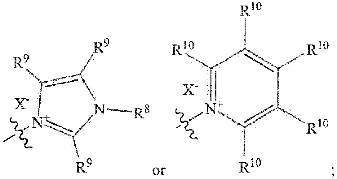
- the cationic polymers include those polymers represented by Formula I or Formula II: and In the above Formulae, each R 1 is individually alkylene, cycloalkylene, or heterocycloalkylene; R 2 is H; each R 4 is individually an alkylene, cycloalkylene, or heterocycloalkylene; each R 5 is individually absent, alkylene, cycloalkylene, or heterocycloalkylene; each R 6 is individually absent or alkylene; each R 7 is individually a group of formula -[P(R 13 ) 3] + , -[N(R 11 ) 3 ] + , each n and p indicate a repeat unit of the polymer; each q is individually 1, 2, or 3; individually T is individually absent, C(O), or CH 2 ; R 8 is alkyl, cycloalkyl, or heterocycloalkyl; each R 9 is individually H, F, Br, Cl, NO 2 , alkyl, cycloalkyl, alkoxy, aryl,
- repeat units identified by the parentheticals are merely blocked representations of an indeterminate number of repeat units spaced throughout the polymer. Although no such recitation of specific values is required to accurately represent a polymer, to the extent values must be assigned to each of n and p, such values may be from 10 to 100 for n and from 2 to 50 for p individually. In some embodiments, this includes from 10 to 60 for n and from 4 to 20 for p.
- the R 7 group in addition to other potential substituents on the polymer, provides at least one site for incorporation of a cationic portion (i.e., "residue") in the polymer.
- the cationic residue may be from about 10 mol% to about 50 mol % based upon the repeating units that are designated by the p. This may include from about 10 mol% to about 40 mol %; about 10 mol% to about 35 mol %; about 10 mol% to about 30 mol %; about 15 mol% to about 50 mol %; about 15 mol% to about 40 mol %; about 15 mol% to about 35 mol %; or about 15 mol% to about 35 mol %.
- the cationic residue may be from about 15 mol% to about 35 mol % of the polymer.
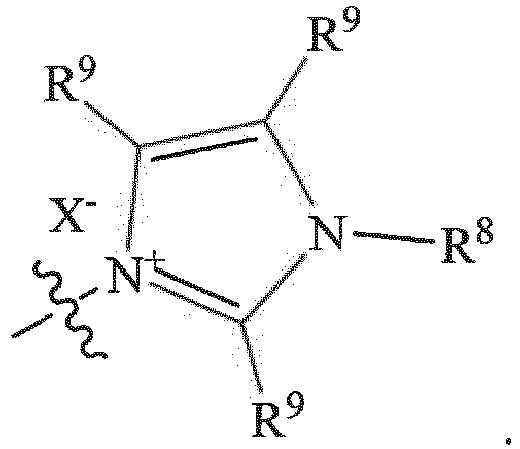
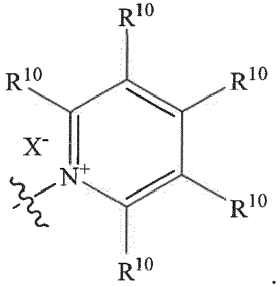
- each R 7 may be Alternatively, in any of the above embodiments, each R 7 may be For illustrative purposes, these cations are attached to the polymer backbone through the nitrogen atoms on the cation ring. It can also be anticipated that the cation rings can be covalently bound to the organic cations through the R 9 and R 10 groups on the rings.
- each R 7 is a -[P(R 13 ) 3 ] + , where R 13 is aryl, and in some embodiments phenyl.
- each R 7 is a -[N(R 11 ) 3 ] + , where R 11 is C 1 -C 8 alkyl.
- anions include, but are not limited to, F - , Cl - , Br - , I - , BF 4 - , PF 6 - , SbF 6 - , AsF 6 - , ClO 4 - , SO 3 CF 3 - , N(CF 3 SO 2 ) 2 - , C(CF 3 SO 2 ) 3 - , triflate (trifluoromethansulfonate), N(SO 2 C 2 F 5 ) - , BAr 4 - , and a mixture of any two or more such anions, wherein Ar is an aryl or fluorinated aryl or a bis(trifluoromethyl)aryl group.
- R 6 may be -CH 2 -.
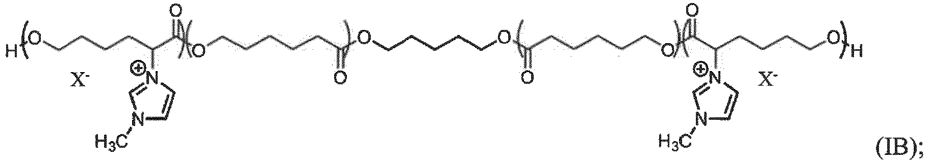
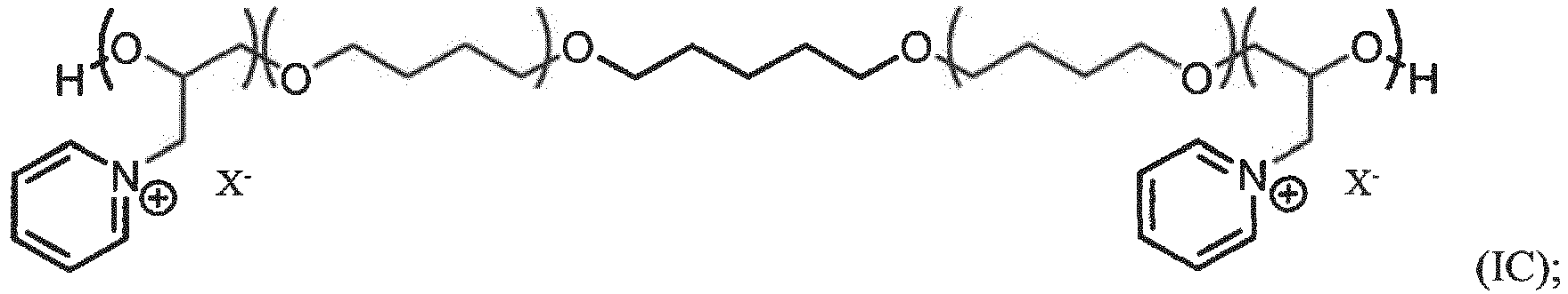
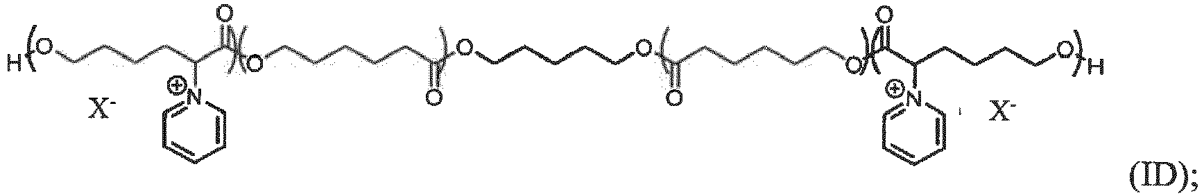
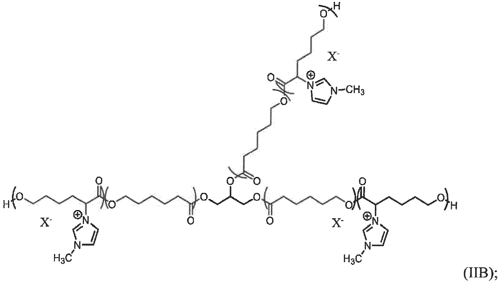
- Illustrative compounds according to Formulae I and II include, but are not limited to those of Formulae IA-D and IIA-D: and In Formulae IA-D and IIA-D, and as above, the parentheses indicate repeat units of the polymer. To the extent specific values are required, they are stated above.
- the cationic polymers of the transparent, ion-selective membranes described herein may be further cross-linked with a cross-linking agent.
- a cross-linking agent may include, but are not limited to di-, tri- and polyisocyanates.
- the transparent, ion-selective membranes described herein with regard to the polycaprolactone-based polymers may have number average molecular weights from about 10,000 to about 250,000 Daltons. This includes, but is not limited to, illustrative ranges such as from about 50,000 to about 180,000 Daltons; about 50,000 to about 160,000 Daltons; or about 80,000 to about 160,000 Daltons.
- the transparent, ion-selective membranes described herein with regard to the polyether polyols may have number average molecular weights from about 500 to about 20,000 Daltons. These include, but are not limited to, illustrative ranges such as from about 1,000 to about 12,000 Daltons; about 1,000 to about 8,000 Daltons; or about 1,400 to about 8,000 Daltons.
- the device 100 includes at least one cathodic chamber 110 and at least one anodic chamber 115.
- the cathodic chamber 110 is defined by a first substrate 135 having a conductive surface 136 and an outer surface 137, and a cathodic face 121 of a separator layer 120.
- the anodic chamber 115 is defined by a second substrate 140 having a conductive surface 141 and an outer surface 142, and an anodic face 122 of the separator layer 120, where the separator is a transparent, ion-selective membrane.
- the conductive surface 136 of the first substrate 135 being joined to the conductive surface 141 of the second substrate 140 by a sealing member 125 (the seal is a unitary element at the perimeter of the device and chambers, despite its apparent separation in the figure).
- the cathodic and anodic materials may be in a solution phase, or a gel phase, within the chambers 110, 115; the cathodic material may be confined to the conductive surface 136, while the anodic material is either in solution or confined to the conductive surface 141; or the anodic material may be confined to the conductive surface 141, while the cathodic material is either in solution or confined to the conductive surface 136.
- Within the chambers 110,115, and within the separator layer 120 is disposed an electrolyte.
- the electrolyte may include the anodic and/or cathodic materials.
- the first 135 and second 140 substrates may be off-set with respect to one another to allow for electric contact to be made with their respective conductive surfaces 136, 141, as is well established for other solution phase electrochromic devices.
- FIG. 2 illustrates a method of constructing devices.
- a device may be constructed of a first substrate 210 and second substrate 270 separated by an ion exchange membrane 240. Both the first substrate 210 and second substrate 270 are coated with a conductive layer on the sides facing the other substate.
- Anodic and cathodic chambers are formed by the substrates 210, 270 and the ion exchange membrane 240 separated by gaskets 220, 250.
- Ion exchange membrane 240 must be strongly bonded to gaskets 220, 250 to withstand pressure differentials during the vacuum assisted backfilling process.
- Fill ports 230, 260 provide conduits for filing the separate chambers with the anodic/cathodic media under vacuum assisted backfilling.
- Adhesive materials like an epoxy, may be used to bind the first substrate 210 to the first gasket 220, the gasket 220 to a first surface of the ion exchange membrane 240, a second surface of the ion exchange membrane 240 to the second gasket 250, and the second gasket 250 to the second substrate 270.
- the sizing of the gaskets and ion exchange membrane may be such that the first substrate is directly bonded to the second substrate, but with the binding adhesive binding and/or abutting an outer edge of the gaskets such that each chamber is sealed, but only a single layer of laminating adhesive is observed from an outer edge of the device.
- the substrates may be made of glass or plastics.
- the gaskets may likewise be made of glass, plastics, rubbers, and the like.
- the only limitation of the substrates and gaskets are that the materials they are constructed of are to be compatible with the electrochromic media and adhesive materials.
- an electrochromic device 300 is formed from a layered anodic gel 310 and a cathodic gel 330 separated by a separator layer 320 that is a transparent, ion-selective membrane.
- a separator layer 320 that is a transparent, ion-selective membrane.
- substrates 360, 361 having conductive layers 350, 351, and bus bar connectors 340, 341.
- the substrates may be a material such as, but not limited to, polyethyleneterephthalate (PET); the conductive layers may be materials such, but not limited to indium tin oxide; and the bus bars may be made of conductive materials such as metals (i.e., copper, stainless steel, silver, gold, iron, or other metals, alloys of any two or more thereof, or blends of any two or more thereof).
- FIG. 4 illustrates a device 400 that includes device 300 between further substrates 410 having barrier seals 420, 421 therebetween. Also, with the chamber formed by the further substrates 410 and barrier seals 420, 421, may optionally be a fluid, clear adhesive, or laminate 430.
- the further substrates may be materials such as glass, while the adhesives may be epoxies, or other adherent, clear materials or laminates such as, but not limited to ethylene-vinyl acetate (EVA) and polyvinylbutyral (PVB).
- EVA ethylene-vinyl acetate
- PVB polyvinylbutyral
- the cathodic material may be a viologen, a low-dimerizing viologen, a non-dimerizing viologen, or metal oxides such as tungsten oxides as those terms are used in the art.
- the term low-dimerizing viologen is applied to some viologens that show dimerization characteristics to a lesser extent than dimerizing viologens.
- Illustrative viologens include, but are not limited to, methyl viologen, octyl viologen, benzyl viologen, and polymeric viologens.
- further viologens are described in U.S. Patent Nos. 4,902,108 ; 6,188,505 ; 5,998,617 ; and 6,710,906 ; and in U.S. Patent Appl. Publication. No. 2015/0346573 .
- the anodic materials may include, but are not limited to, metallocenes, 5,10-dihydrophenazines, phenothiazines, phenoxazines, carbazoles, triphendioxazines, triphenodithiazines and related compounds.
- Anodic materials included in the electrochromic medium may include any one of a number of materials including ferrocene, substituted ferrocenes, substituted ferrocenyl salts, phenazine, substituted phenazines, phenothiazine, substituted phenothiazines, including substituted dithiazines, thianthrene, and substituted thianthrenes.
- Examples of anodic materials may include di-tert-butyl-diethylferrocene, 5,10-dimethyl-5,10-dihydrophenazine (DMP), bis(triethylaminopropyl)dihydrophenazine bis(tetrafluoroborate), 3,7,10-trimethylphenothiazine, 2,3,7,8-tetramethoxy-thianthrene, 10-methylphenothiazine, tetramethylphenazine (TMP), and bis(butyltriethylammonium)-para-methoxytriphenodithiazine (TPDT).
- DMP 5,10-dimethyl-5,10-dihydrophenazine
- TMP bis(triethylaminopropyl)dihydrophenazine bis(tetrafluoroborate)
- TMP tetramethylphenazine
- TPDT bis(butyltriethylammoni
- the anodic material may include a polymer film, such as polyaniline, polythiophenes, polymeric metallocenes, or a solid transition metal oxide, including, but not limited to, oxides of vanadium, nickel, iridium, as well as numerous heterocyclic compounds, etc. It will be understood that numerous other anodic materials are contemplated for use including those disclosed in U.S. Pat. Nos. 4,902,108 ; 6,188,505 ; 6,710,906 ; and 7,428,091 .
- at least one of the anodic electroactive material includes a substituted or unsubstituted phenazine compound.
- At least one of the anodic electroactive material includes a substituted or unsubstituted 2,7-dialkyl-5,10-dialkyl-5,10-dihydrophenazine compound.
- at least one alkyl group of the 5,10-dialkyl groups attached to the phenazine compound includes at least 4 carbon atoms and is void of any ⁇ hydrogen atoms, and at least one alkyl group of the 2,7-dialkyl groups attached to the phenazine compound includes at least 4 carbons.
- At least one alkyl group of the 5,10-dialkyl groups attached to the phenazine compound includes a substituted or unsubstituted neopentyl group
- at least one alkyl group of the 2,7-dialkyl groups attached to the phenazine compound includes a substituted or unsubstituted isopropyl, isobutyl, (2-ethylbutyl), or (2-propylpentyl) group.
- At least one alkyl group of the 5,10-dialkyl groups attached to the phenazine compound includes a neopentyl group, and at least one alkyl group of the 2,7-dialkyl groups attached to the phenazine compound includes a 2-ethyl-1-butanol group.
- at least one alkyl group of the 5,10-dialkyl groups attached to the phenazine compound includes a neopentyl group, and at least one alkyl group of the 2,7-dialkyl groups attached to the phenazine compound includes an isobutyl group.
- at least one alkyl group of the 5,10-dialkyl groups attached to the phenazine compound also includes a cation like quaternized ammonium or phosphonium group.
- the electrochromic medium includes a solvent and a salt.
- a solvent of the electrochromic medium may include, but is not limited to, 3-methylsulfolane, dimethyl sulfoxide, dimethyl formamide, tetraglyme and other polyethers; alcohols such as ethoxyethanol; nitriles, such as acetonitrile, glutaronitrile, 3-hydroxypropionitrile, and 2-methylglutaronitrile; ketones including 2-acetylbutyrolactone, and cyclopentanone; cyclic esters including beta-propiolactone, ⁇ -bulyrolactone, ⁇ -valerolactone; propylene carbonate (PC), ethylene carbonate; oligoethers; and homogenous mixtures of any two or more such solvents.
- PC propylene carbonate
- the electrochromic composition may include a solvent that includes propylene carbonate. While specific solvents have been disclosed as being associated with the electrochromic composition, numerous other solvents that would be known to those having ordinary skill in the art having the present disclosure before them are likewise contemplated for use.
- the electrochromic medium may include a polymeric gel composition. Illustrative polymer matrix materials used in electrochromic device gel systems may be found in US Patent Nos. 6,635,194 and 5,940,201 .
- the salt may be a metal salt or an ammonium salt.
- Illustrative salts include, but are not limited to, metal or ammonium salts, such as but not limited to Li + , Na + , K + , NR' 4 + , where each R' is individually H, alkyl, or cycloalkyl, of the following anions F - , Cl - , Br - , I - , BF 4 - , PF 6 - , SbF 6 - , AsF 6 - , ClO 4 - , SO 3 CF 3 - , N(CF 3 SO 2 ) 2 - , C(CF 3 SO 2 ) 3 - , N(SO 2 C 2 F 5 ) - , Al(OC(CF 3 ) 3 ) 4 - , or BAr 4 - , wherein Ar is an aryl or fluorinated aryl group such as, but not limited to, C 6 H 5 , 3,5-(CF 3
- the electrochromic devices described herein exhibit a high transmission state at short circuit and a low transmission state upon application of an electric potential.
- the high transmission state is at least 5 times greater than the low transmission state; and the electrochromic device is configured to maintain a transmission percentage within 5% of the low transmission state for at least 8 hours at open circuit after application of a potential sufficient to reach to the low transmissions state.
- the low transmission state may range from a transmission for the device of about 0.001% to about 30%, while the high transmission state may be from about 50% to about 95%.
- a high transmission value does not vary by more than 5% from an initial high transmission value.
- the initial high transmission value is the state of the device prior to the application of an electric potential after device fabrication. In some embodiments, after 4000 cycles from high transmission to low transmission, the low transmission value does not vary by more than 5% from an initial low transmission value. As used herein, the initial low transmission value is the low transmission value achieved upon the first charging of the device at a full voltage application. As used herein, the transmission refers to transmission of the full visible spectrum and is not limited to a single wavelength.
- the substrates and conductive coatings on the substrates those typically used in solution-based electrochromic devices may be used.
- the one or both substrates may be glass, metal, plastic, or ceramic.
- the conductive coating on one or more of the substrates may be transparent or opaque depending upon the intended use of the device. For example, where the device is a window, both coatings should be substantially transparent, and where the device is a mirror at least one coating is transparent.
- transparent conductive materials include, but are not limited to, fluorine doped tin oxide (FTO), indium/tin oxide (ITO), doped zinc oxide, indium zinc oxide, metal oxide/Ag/metal oxide, silver nano-wire coatings, carbon nanotubes, graphene coatings, wire grids, conductive polymers such as, but not limited to, poly(3,4-ethylenedioxythiophene) (PEDOT).
- FTO fluorine doped tin oxide
- ITO indium/tin oxide
- doped zinc oxide indium zinc oxide
- metal oxide/Ag/metal oxide silver nano-wire coatings
- silver nano-wire coatings such as, but not limited to, poly(3,4-ethylenedioxythiophene) (PEDOT).
- PEDOT poly(3,4-ethylenedioxythiophene)
- Non-transparent conductive coatings include metal coatings such as rhodium, chromium, nickel, silver, gold, and other metals, or mixtures of any two or
- a cationic polymer may be transparent and may be formed into a membrane as described herein.
- the cationic polymers may have ammonium, pyridinium, imidazolium, or phosphonium functionality; and an oxygenated backbone.
- the polymers may also be cross-linked using a cross-linking agent.
- the cationic polymers include those polymers represented by Formula I or Formula II: and In the above Formulae, each R 1 is individually alkylene, cycloalkylene, or heterocycloalkylene; each R 2 is H; each R 4 is individually an alkylene, cycloalkylene, or heterocycloalkylene; each R 5 is individually absent, alkylene, cycloalkylene, or heterocycloalkylene; each R 6 is individually absent or alkyene; each R 7 is individually a group of formula -[P(R 13 ) 3 ] + ; or -[N(R 11 ) 3 ] + ; each X - is individually an anion; each n and p indicate a repeat unit of the polymer; each q is individually 1, 2, or 3; individually T is individually absent, C(O), or CH 2 ; R 8 is alkyl, cycloalkyl, or heterocycloalkyl; each R 9 is individually H, F, Br, Cl, NO 2 , alkyl,
- repeat units identified by the parentheticals are merely blocked representations of an indeterminate number of repeat units spaced throughout the polymer.
- values may be from 10 to 100 for n and from 2 to 50 for p. In some embodiments, this includes from 10 to 60 for n and from 4 to 20 for p.
- each R 13 is phenyl.
- the R 7 group in addition to other potential substituents on the polymer, provides at least one site for incorporation of the cationic residue in the polymer.
- the cationic residue may be from about 10 mol% to about 50 mol %. This may include from about 10 mol% to about 40 mol %; about 10 mol% to about 35 mol %; about 10 mol% to about 30 mol %; about 15 mol% to about 50 mol %; about 15 mol% to about 40 mol %; about 15 mol% to about 35 mol %; or about 15 mol% to about 35 mol %.
- the cationic residue may be from about 15 mol% to about 35 mol % of the polymer.
- each R 7 may be Alternatively, in any of the above embodiments, each R 7 may be Alternatively, in any of the above embodiments, each R 7 may be -[N(R 11 ) 3 ] + . Alternatively, in any of the above embodiments, each R 7 may be -[P(R 13 )3] + .
- anions include, but are not limited to, F - , Cl - , Br - , I - , BF 4 - , PF 6 - , SbF 6 - , AsF 6 - , ClO 4 - , N(CF 3 SO 2 ) 2 - , C(CF 3 SO 2 ) 3 - , triflate (SO 3 CF 3 ; trifluoromethansulfonate), N(SO 2 C 2 F 5 ) - , BAr 4 - , and a mixture of any two or more such anions, wherein Ar is an aryl or fluorinated aryl or a bis(trifluoromethyl)aryl group.
- R 6 may be -CH 2 -.
- Illustrative cationic polymers according to Formulae I and II include, but are not limited to those of Formulae IA-D and IIA-D: and In Formulae IA-D and IIA-D, and as above, the parentheses indicate repeat units of the polymer. To the extent specific values are required, they are stated above.
- the cationic polymers described herein may be further cross-linked with a cross-linking agent.
- a cross-linking agent may include, but are not limited to di- or tri-isocyanates.
- the cationic polymers described herein have molecular weights from about 1,000 to about 10,000 Daltons. This includes, but is not limited illustrative ranges such as from about 1,000 to about 8,000 Daltons; about 1,000 to about 7,000 Daltons; about 1,000 to about 6,000 Daltons; about 1,500 to about 8,000 Daltons; about 1,500 to about 6,000 Daltons; about 1,500 to about 5,500 Daltons; about 2,000 to about 10,000 Daltons; about 2,000 to about 6,000 Daltons; about 2,000 to about 5,000 Daltons; and about 3,000 to about 6,000 Daltons.
- methods of preparing the transparent, ion-selective polymer membranes include reacting the monomeric constituents of the polymers either neat or in a solvent such as propylene carbonate.
- a polyisocyanate is used with a diol or triol, such as for the preparation of some of the polymers described by Formulae I or II, an isocyanate:hydroxyl ratio may be from about 1.00 to about 1.10.
- Catalysts may be used in the reactions.
- organotin catalysts may be used to effect the isocyanate/alcohol reaction in some embodiments.
- the polymers may be cast or drawn on a release liner (i.e., polyethylene terephthalate or polytetrafluoroethylene) and the solvent removed, or the polymer allowed to cure at either room, or elevated, temperature.
- a release liner i.e., polyethylene terephthalate or polytetrafluoroethylene
- a second release liner may be used over the polymer in a sandwich fashion, if desired.
- Example 1 Preparation of pyridinium-substituted poly(vinyl formal) membrane [Reference Example]. To a reaction vessel was added 4-formyl- N- methylpyridinium tosylate (0.448 g, 1.53 mmol), 10 % (w/w) aqueous poly(vinyl alcohol) (6.00 g, 10.8 mmol OH), and deionized water (3.43 g), followed by 2-3 drops of conc. hydrochloric acid. The mixture was heated to 65 °C and stirred for 2 h, after which 37 % (w/w) aqueous formaldehyde (0.223 g, 2.75 mmol) was added.
- Example 2 Conditioning of pyridinium-substituted poly(vinyl formal) membrane (Example 1) [Reference Example].
- a 4.5 cm x 4.5 cm section of ion-exchange membrane was soaked for 2 minutes in a glass dish containing 40 % w/w aqueous sodium tetrafluoroborate and then soaked for 2 minutes in deionized water.
- the ion-exchange membrane was then soaked for 2 minutes in methanol and soaked for 10 minutes in a 0.500 M solution of tetraethylammonium tetrafluoroborate in propylene carbonate heated to 65 °C.
- the membrane was then removed from the bath and flattened between a pair of PET release liners for later use.
- Example 3 Synthesis of poly(ECH-co-THF) diol.
- THF tetrahydrofuran
- 1,5-pentanediol 6.20 mL, 59.0 mmol
- BF 3 -OEt 2 1.35 mL, 11.0 mmol
- EH epichlorohydrin
- Example 4 Synthesis of poly(ECH-co-THF) tetraol.
- a mixture of pentaerythritol ethoxylate (15.9 g, 59.0 mmol), tetrahydrofuran (121 mL, 1.49 mol), and BF 3 -OEt 2 (1.35 mL, 11.0 mmol) was cooled to 0 °C while stirring under argon, then treated dropwise with epichlorohydrin (50.0 mL, 0.630 mol) added over 45 minutes. The mixture was allowed to warm to ambient temperature upon standing while stirring under Ar for an additional 22 hours, then diluted with dichloroethane (250 mL) and treated with Ca(OH) 2 (6.0 g).
- Example 5 Synthesis of (THF-co-pyridiniumpropylene oxide (“PyPO”)) diol.
- Example 6 Synthesis of (THF-co-PyPO) tetraol.
- a mixture of poly(tetrahydrofuran-co-epichlorohydrin) diol (50.0 g) and pyridine (50.0 g, 632 mmol) was heated to 100 °C and stirred under argon for 20 h.
- the resulting slurry was allowed to cool to 65 °C upon standing and then concentrated under reduced pressure (14 Torr).
- the residue upon cooling to ambient temperature, was dissolved in deionized water (200 mL) and added dropwise to a stirred 40 % w/w solution of NaBF 4 in water (500 mL), during which a tan semi-solid precipitated.
- Example 7 Synthesis of poly(THF-co-GTMA) tetraol.
- a mixture of pentaerythritol ethoxylate (1.86 g, 6.88 mmol), tetrahydrofuran (14.0 mL, 172 mmol), and BF 3 -THF (145 ⁇ L, 1.31 mmol) was cooled to 0 °C while stirring under argon and then treated dropwise with glycidyltrimethylammonium (“GTMA”) bistriflimide (30.0 g, 75.7 mmol) added over 45 minutes.
- GTMA glycidyltrimethylammonium
- Example 8 Curing of poly(THF-co-PyPO) tetraol with hexamethylenediisocyanate trimer ("HDT").
- a 85 % w/w polyol stock solution was prepared by dissolving poly(THF-co-PyPO) (18.0 g) in propylene carbonate (3.18 g), and an isocyanate/catalyst stock solution was prepared by mixing HDT (5.65 g) and propylene carbonate (1.00 g) with 10.0 % w/w Bu 2 Sn(OAc) 2 in propylene carbonate (0.237 g).
- Example 9 Build an Electrochromic device with pyridinium-substituted poly(vinyl formal) membrane [Reference Example].
- Anodic gel to a 20 mL scintillation vial were added tetraethylammonium tetrafluoroborate (Et 4 NBF 4 )(0.109 g, 0.502 mmol), glass spacer beads (250 ⁇ m, 0.300 g), and propylene carbonate (5.53 g). The mixture was gently agitated until the Et 4 NBF 4 dissolved and was then purged with argon for 20 minutes.
- Et 4 NBF 4 tetraethylammonium tetrafluoroborate
- Spacer paste to a 20 mL scintillation vial were added glass spacer beads (600 ⁇ m, 0.630 g), propylene carbonate (5.34 g), and fumed silica (0.400 g), and the slurry was vigorously stirred with a wooden applicator.
- a "splat" cell was constructed using indium tin oxide ("ITO") coated 3x3 inch glass squares. Onto each of the four corners of the ITO-coated side of one piece of glass was evenly deposited a dot of spacer paste. Near the center of the glass square, on the ITO coated side, was then deposited a portion of the anodic gel. A strip of conditioned cationic acetal membrane from Example 2 was gently flattened between the dots of spacer paste and pressed against the deposited anodic gel. A portion of cathodic gel was then applied on top of the membrane and aligned with the anodic gel layer.
- ITO indium tin oxide
- the second piece of ITO-coated glass was placed atop the stacked assembly with the ITO coating in contact with the anodic gel.
- the two pieces of glass were held together, electrical contacts were made with each ITO coating independently through the use of bus clips and connector wires, and the whole device was placed in an enclosure and purged with Ar for 1 hour.
- the "splat" cell device was powered at 1.0 V in a reverse bias configuration for 1 minute, during which time the device remained colorless. The device was then powered at 1.0 V with forward bias for 10 seconds, and the device became dark where the anodic, cathodic and membrane stack resided. After 10 seconds, no further darkening was observed. The device was then left in an open-circuit configuration and observed at multiple intervals (e.g., 15 min, 30 min, 1 h, 2 h, 3 h, and 4 h after darkening). During this 4 hour period, no fading of the device was observed.
- the cationic, vinyl acetal membrane investigated led to excellent dynamic range, kinetics, and color-retention in a 3-layer electrochromic device constructed from separated cathodic and anodic chromophore gels.
- Example 10 [Reference Example]. The general description of the construction of an electrochromic device with a transparent ion exchange membrane (Example 2) embedded into the edges of a thermally cured epoxy perimeter seal, as shown in FIG. 2 . With this device construction, glass gaskets on each side of the membrane were used to set the distance from each ITO coated glass substrate, creating the two electrochromic chambers, anodic and cathodic, with the transparent ion-selective membrane sandwiched between them. The gaps in each gasket allowed for the placement of small glass capillaries that functioned as ports for vacuum evacuation of the device and subsequent backfilling with electrochromic fluid.
- Stepwise construction of the device is as follows: 1) the pre-cut glass gasket and two glass capillaries were arranged on a release liner in a lay-up jig; 2) the epoxy was dispensed around the capillaries and at the perimeter of the desired membrane location; 3) a glass filler plug was positioned inside the gasket to provide a continuous flat surface, and then a membrane was aligned with the epoxy and pressed flat; 4) epoxy was dispensed on top of the membrane and aligned with the epoxy below it; 5) the second gasket was positioned and capillary tubes were embedded as in steps 1-2 and then the epoxy pressed flat; 6) epoxy was dispensed in the same pattern on the second gasket and capillary tubes, and then an outer plate was placed over the epoxy and pressed flat; 7) epoxy seals were allowed to cure at ambient temperature overnight; 8) the assembly was removed from the jig, inverted, and replaced in the jig and the glass filler plug removed; 9) epoxy was dispensed matching the prior
- An electrochromic solution was made by dissolving a cathodic material, 5.7 millimolar bis(octyl)viologen bis(tetrafluoroborate) and an anodic material, 4.05 millimolar bis(triethylaminopropyl)dihydrophenazine bis(tetrafluoroborate) with 0.5 millimolar decamethyl ferrocenium tetrafluoroborate; 0.5 millimolar decamethylferrocene, 0.10 molar tetraethylammonium tetrafluoroborate, 2.8% by weight of a copolymer of 2-hydroxyethylmethacrylate and methylacrylate (mole ratio of momomers in polymer at 1/10, respectively), 0.19% by weight methylene diphenyl diisocyanate, and 1.0 ppm of dibutyltin diacetate in a solvent, propylene carbonate.
- This electrochoromic solution was vacuum-filled into chambers on both
- the electrochromic fluid After allowing the electrochromic fluid to gel, a power supply was connected to the two ITO electrodes and the device was powered at 1.2 volts. The electrochromic device darkened quickly (20 - 30 s), then the device was held at open circuit. In open circuit, the electrochromic device retained color for greater than 24 hours. The devices cleared within approx. 30 - 45 s by placing a short across the two ITO electrodes.
- Example 11 Membrane electrochromic device on a transparent conductor/PET substrates using conditioned membrane from Example 2 [Reference Example].
- TCO/PET polyethylene terephthalate
- IMI inorganic-metallic-inorganic conductive stack (7 ohms per square
- Multilayer device consisting of (general stackup): PET/TCO/Cathodic Gel/Ion Exchange Membrane/Anodic Gel/transparent conductor/PET.
- PET is an abbreviation for polyethyleneterephthalate
- TCO is a transparent conductive oxide.
- Cathodic and anodic gel drawdown coatings were made on separate pieces of IMI (inorganic-metallic-inorganic silver stack (7 ohms per square) on PET using a doctor blade with a 200 micron gap (other stacks of layers that were employed include PET/inorganic-metallic-inorganic layer/TCO). The coatings were allowed to gel overnight at ambient temperature in a nitrogen box, after which the thickness of each gel coating was 100 microns.
- a conditioned ion exchange membrane (Example 2) was flattened atop the cathodic layer, and the anodic layer was then flattened atop the membrane. Pressure was applied with a roller to ensure good contact between the layers. Bus bars were affixed to the transparent conducting films (in some instances, devices prepared in this manner were placed between matching sheets of glass using a liquid, optically clear adhesive and a barrier sealant around the edge). Device transmission and current were measured while applying a potential of 1.2 V for 3 min, while holding the device in an open circuit configuration, and then shorting the device for 3 min.
- the device remained in the darkened state overnight (20 hours) while in an open circuit configuration.
- the device cleared within 3 minutes upon applying 1.2 V in reverse bias.
- Example 12 Comparison of no membrane, SpectraPor X, and Nafion 115-Li + .
- Preparation of Nafion 115-Li + membrane A 10 cm x 10 cm piece of Nafion 115 was soaked in 250 mL 3% H 2 O 2 at 80 °C for two hours. The membrane was rinsed with water then soaked in 250 mL 0.1% HCl at 80 °C for one hour then cooled to room temperature overnight. The membrane was then rinsed with water then soaked in 500 mL 2 M LiOH at 80 °C for two hours. The membrane was rinsed with water then soaked in 300 mL water and deoxygenated with bubbling argon for 16 hours.
- Spectra/Por 1 membrane Preparation of Spectra/Por 1 membrane.
- a section of Spectrum Laboratories Spectra/Por 1 (MWCO: 6-8000, 50 mm flat width) size exclusion membrane of 10 cm length was cut lengthwise to create a sheet of 10 cm x 10 cm.
- the membrane was soaked in 300 mL water that was changed twice over an hour of soaking.
- the membrane was then soaked in 300 mL water and deoxygenated with bubbling argon for 16 hours.
- EC elements Preparation and Operation of EC elements.
- the elements were assembled in a box purged with argon to limit exposure of the electrolyte to oxygen.
- Each element consisted of two 7.5 cm x 7.5 cm glass electrodes each coated with half wave ITO and facing each other. The electrodes were separated by two layers of 254 ⁇ m thick skived PTFE tape for a total cell spacing of 508 ⁇ m.
- the membrane was placed between the two layers of spacer tape.
- the compartment(s) were filled with the electrolyte.
- the elements were then powered at 1.2 V. After the three elements were fully colored, the potential was removed and the elements left at open circuit.
- the reference element with no membrane cleared within 7 minutes.
- the element with the Spectra/Por size exclusion membrane cleared after 2 hours.
- the element with Nafion-Li + was still colored after >3 hours but had cleared overnight.
Landscapes
- Chemical & Material Sciences (AREA)
- Chemical Kinetics & Catalysis (AREA)
- Engineering & Computer Science (AREA)
- Manufacturing & Machinery (AREA)
- Polymers & Plastics (AREA)
- Health & Medical Sciences (AREA)
- Medicinal Chemistry (AREA)
- Organic Chemistry (AREA)
- Physics & Mathematics (AREA)
- Nonlinear Science (AREA)
- Inorganic Chemistry (AREA)
- Materials Engineering (AREA)
- Optics & Photonics (AREA)
- General Physics & Mathematics (AREA)
- Electrochromic Elements, Electrophoresis, Or Variable Reflection Or Absorption Elements (AREA)
- Addition Polymer Or Copolymer, Post-Treatments, Or Chemical Modifications (AREA)
- Polyethers (AREA)
Description
- The present technology is generally related to electrooptical devices. More particularly, it is related to electrochromic devices having a persistent color memory for a substantial time period once being charged and after voltage removed. The present technology is also related to polymeric materials and ion exchange or ion selective membranes.
In this context,WO 2016/145120 A1 describes an electrochromic device including a first flexible or rigid plastic substrate including a front surface, and a rear surface, wherein the rear surface comprises a first conductive material; and the front surface, the rear surface, or both the front surface and the rear surface of the first substrate comprises a gas diffusion barrier; and a second flexible or rigid plastic substrate including a front surface, and a rear surface, wherein the front surface comprises a second conductive material, wherein the first substrate is joined to the second substrate by a sealing member, where the rear surface of the first substrate and the front surface of the second substrate with the sealing member define a chamber therebetween. Furthermore,US 2015/076390 A1 describes an electrochromic device including a first substantially transparent substrate having an electrically conductive material associated therewith; a second substrate having an electrically conductive material associated therewith; and an electrochromic medium contained within a chamber positioned between the first and second substrates which includes: at least one solvent; at least one anodic electroactive material; at least one cathodic electroactive material; wherein at least one of the anodic and cathodic electroactive materials is electrochromic; and a creep resistant crosslinked polyelectrolyte gel matrix.
Moreover,US 2014/138589 A1 describes a composition containing a nano-carbon material, such as a carbon nanotube, and a polyether-based polymer containing oxirane monomer units at least part of which are oxirane monomer units each having a cationic group. - In one aspect, a cationic polymer is provided as represented by Formula I or Formula II:

- each R1 may be individually alkylene, cycloalkylene, or heterocycloalkylene;
- R2 may be H;
- each R4 may be individually alkylene, cycloalkylene, or heterocycloalkylene;
- each R5 may be individually absent or alkylene, cycloalkylene, or heterocycloalkylene;
- each R6 may be individually absent or alkylene;
- each R7 may be individually a group of formula:


- R8 is individually alkyl, cycloalkyl, or heterocycloalkyl;
- each R9 may be individually H, F, Br, Cl, NO2, alkyl, cycloalkyl, alkoxy, aryl, or heteroaryl, or any two individual R9 groups may join together to form a ring which may be saturated or unsaturated;
- each R10 may be individually H, F, Br, Cl, NO2, alkyl, cycloalkyl, alkoxy, aryl, or heteroaryl, or any two individual R10 groups may join together to form a ring which may be saturated or unsaturated;
- each R11 may be individually alkyl, cycloalkyl, aryl, or heteroaryl, or any two individual R11 groups may join together to form a ring which may be saturated or unsaturated;
- each R13 may be individually alkyl or aryl;
- each X- may be individually an anion;
- each n and p indicate a repeat unit of the polymer;
- each q may be individually 1, 2, or 3;
- each T may be individually absent, C(O), or CH2; and
- each T' may be individually absent or C(O).
- In some embodiments of the above formulae, each R1 may be individually C1-C6 alkylene, C3-C16 cycloalkylene, or C3-C16 heterocycloalkylene; R2 may be H; each R3 may be individually C1-C6 alkyl, C3-C16 cycloalkyl, or C3-C16 heterocycloalkyl; each R4 maybe individually C1-C6 alkylene, C3-C16 cycloalkylene, or C3-C16 heterocycloalkylene; each R5 may be individually absent or C1-C6 alkylene, C3-C16 cycloalkylene, or C3-C16 heterocycloalkylene; each X- may be individually an anion; and q is 2.
- In any embodiments of the above formulae, R6 may be -CH2-.
- In another aspect, an electrochromic device includes a cathodic compartment including a cathodic material; an anodic compartment including an anodic material; and a transparent, ion-selective membrane displaced between the cathodic compartment and the anodic compartment; wherein the transparent, ion-selective membrane includes a cationic polymer. In some embodiments of the device, the cationic polymer includes ammonium, phosphonium, pyridinium, or imidazolium functionality; and an oxygenated backbone. In some embodiments, the electrochromic devices includes any of the cationic polymers described herein by any one or more of Formula I or Formula II. In some embodiments, the transparent, ion-selective membrane comprises an anionic polymer and one or both the cathodic and anodic materials are anions in the activated state. In other embodimetns, the transparent, ion-selective membrane comprises a cationic polymer and one or both the cathodic and anodic materials are cations in the activated state.
-
-
FIG. 1 is a cross-sectional view of an electrochromic device, according to one embodiment. -
FIG. 2 is an illustration of the layup proceed for forming an electrochromic device, according to one embodiment. -
FIG. 3 is a schematic figure of a first alternative layered structure for the electrochromic device, according to one embodiment. -
FIG. 4 is a schematic figure of a second alternative layered structure for the electrochromic device, according to one embodiment. - Various embodiments are described hereinafter. It should be noted that the specific embodiments are not intended as an exhaustive description or as a limitation to the broader aspects discussed herein. One aspect described in conjunction with a particular embodiment is not necessarily limited to that embodiment and can be practiced with any other embodiment(s).
- As used herein, "about" will be understood by persons of ordinary skill in the art and will vary to some extent depending upon the context in which it is used. If there are uses of the term which are not clear to persons of ordinary skill in the art, given the context in which it is used, "about" will mean up to plus or minus 10% of the particular term.
- The use of the terms "a" and "an" and "the" and similar referents in the context of describing the elements (especially in the context of the appended claims) are to be construed to cover both the singular and the plural, unless otherwise indicated herein or clearly contradicted by context. Recitation of ranges of values herein are merely intended to serve as a shorthand method of referring individually to each separate value falling within the range, unless otherwise indicated herein, and each separate value is incorporated into the specification as if it were individually recited herein. All methods described herein can be performed in any suitable order unless otherwise indicated herein or otherwise clearly contradicted by context. The use of any and all examples, or exemplary language (e.g., "such as") provided herein, is intended merely to better illuminate the embodiments and does not pose a limitation on the scope of the claims unless otherwise stated. No language in the specification should be construed as indicating any non-claimed element as essential.
- In general, "substituted" refers to an alkyl, alkenyl, alkynyl, aryl, or ether group, as defined below (e.g., an alkyl group) in which one or more bonds to a hydrogen atom contained therein are replaced by a bond to non-hydrogen or non-carbon atoms. Substituted groups also include groups in which one or more bonds to a carbon(s) or hydrogen(s) atom are replaced by one or more bonds, including double or triple bonds, to a heteroatom. Thus, a substituted group will be substituted with one or more substituents, unless otherwise specified. In some embodiments, a substituted group is substituted with 1, 2, 3, 4, 5, or 6 substituents. Examples of substituent groups include: halogens (i.e., F, Cl, Br, and I); hydroxyls; alkoxy, alkenoxy, alkynoxy, aryloxy, aralkyloxy, heterocyclyloxy, and heterocyclylalkoxy groups; carbonyls (oxo); carboxyls; esters; urethanes; oximes; hydroxylamines; alkoxyamines; aralkoxyamines; thiols; sulfides; sulfoxides; sulfones; sulfonyls; sulfonamides; amines; N-oxides; hydrazines; hydrazides; hydrazones; azides; amides; ureas; amidines; guanidines; enamines; imides; isocyanates; isothiocyanates; cyanates; thiocyanates; imines; nitro groups; nitriles (i.e., CN); and the like.
- As used herein, "alkyl" groups include straight chain and branched alkyl groups having from 1 to about 20 carbon atoms, and typically from 1 to 12 carbons or, in some embodiments, from 1 to 8 carbon atoms. As employed herein, "alkyl groups" include cycloalkyl groups as defined below. Alkyl groups may be substituted or unsubstituted. Examples of straight chain alkyl groups include methyl, ethyl, n-propyl, n-butyl, n-pentyl, n-hexyl, n-heptyl, and n-octyl groups. Examples of branched alkyl groups include, but are not limited to, isopropyl, sec-butyl, t-butyl, neopentyl, and isopentyl groups. Representative substituted alkyl groups may be substituted one or more times with, for example, amino, thio, hydroxy, cyano, alkoxy, and/or halo groups such as F, Cl, Br, and I groups. As used herein the term haloalkyl is an alkyl group having one or more halo groups. In some embodiments, haloalkyl refers to a per-haloalkyl group.
- Cycloalkyl groups are cyclic alkyl groups such as, but not limited to, cyclopropyl, cyclobutyl, cyclopentyl, cyclohexyl, cycloheptyl, and cyclooctyl groups. In some embodiments, the cycloalkyl group has 3 to 8 ring members, whereas in other embodiments the number of ring carbon atoms range from 3 to 5, 6, or 7. Cycloalkyl groups may be substituted or unsubstituted. Cycloalkyl groups further include polycyclic cycloalkyl groups such as, but not limited to, norbornyl, adamantyl, bornyl, camphenyl, isocamphenyl, and carenyl groups, and fused rings such as, but not limited to, decalinyl, and the like. Cycloalkyl groups also include rings that are substituted with straight or branched chain alkyl groups as defined above. Representative substituted cycloalkyl groups may be mono-substituted or substituted more than once, such as, but not limited to: 2,2-; 2,3-; 2,4-; 2,5-; or 2,6-disubstituted cyclohexyl groups or mono-, di-, or tri-substituted norbornyl or cycloheptyl groups, which may be substituted with, for example, alkyl, alkoxy, amino, thio, hydroxy, cyano, and/or halo groups.
- Alkenyl groups are straight chain, branched or cyclic alkyl groups having 2 to about 20 carbon atoms, and further including at least one double bond. In some embodiments alkenyl groups have from 2 to 12 carbons, or, typically, from 2 to 8 carbon atoms. Alkenyl groups may be substituted or unsubstituted. Alkenyl groups include, for instance, vinyl, propenyl, 2-butenyl, 3-butenyl, isobutenyl, cyclohexenyl, cyclopentenyl, cyclohexadienyl, butadienyl, pentadienyl, and hexadienyl groups among others. Alkenyl groups may be substituted similarly to alkyl groups. Divalent alkenyl groups, i.e., alkenyl groups with two points of attachment, include, but are not limited to, CH-CH=CH2, C=CH2, or C=CHCH3.
- As used herein, "aryl", or "aromatic," groups are cyclic aromatic hydrocarbons that do not contain heteroatoms. Aryl groups include monocyclic, bicyclic and polycyclic ring systems. Thus, aryl groups include, but are not limited to, phenyl, azulenyl, heptalenyl, biphenylenyl, indacenyl, fluorenyl, phenanthrenyl, triphenylenyl, pyrenyl, naphthacenyl, chrysenyl, biphenyl, anthracenyl, indenyl, indanyl, pentalenyl, and naphthyl groups. In some embodiments, aryl groups contain 6-14 carbons, and in others from 6 to 12 or even 6-10 carbon atoms in the ring portions of the groups. The phrase "aryl groups" includes groups containing fused rings, such as fused aromatic-aliphatic ring systems (e.g., indanyl, tetrahydronaphthyl, and the like). Aryl groups may be substituted or unsubstituted.
- Unless expressly stated otherwise, reference to any group, e.g., alkyl, aryl, heteroaryl, heterocyclyl, cyclyl, alkenyl, alkynyl, etc., includes reference to both substituted and unsubstituted such groups.
- One of the advantages of solution-based electrochromic devices is that they are very stable to chemical durability testing (weathering). However, one disadvantage, at least for some applications, for a single-compartment, self-erasing, solution-based electrochromic device is that constant power is needed to be applied to a device in order for it to remain in the darken state. The constant power consumption makes some applications difficult or prohibitive. Herein is provided a multi-compartment device that is able to maintain a darkened, or low-transmission state, at open circuit. The multi-compartment devices include a cathodic compartment and an anodic compartment, with a separator layer therebetween. Additionally, the separator layer includes a colorless, or at least nearly colorless, transparent, chemically stable, ion exchange membrane. Such membranes allow for the free diffusion of an electrolyte of a particular charge through the membrane, but prohibit (or at least significantly impede) the free passage of the opposite charge. For example, if the membrane is a cationic membrane, it will allow for passage of anions while excluding cations, and vice versa. Thus, where the device is in an electrochemically active and/or darkened state, passage of one charged type of ion is allowed while impeding the passage of the opposite charged ion.
- In the devices described herein, the anodic and cathodic redox active materials should be soluble ionic compounds of the same charge (i.e., negative or positive), while in the electrochemically active and/or darkened state and the membrane separating the redox active media should only allow passage of the opposite charge, either from a supporting electrolyte or the counter-ion associated with the electrochromic material(s). For example, if the cathodic and/or anodic materials are both positively charged in the active and/or darkened state, the ion exchange membrane should be an anion exchange membrane. Alternatively, if the cathodic and anodic materials are both negatively charged in the active and/or darkened state, the ion exchange membrane should be a cation exchange membrane. The electrolyte of the opposite charge to the membrane may be either from a supporting electrolyte and/or the counter-ion from either redox electroactive anodic or cathodic material. Once the device is subjected to a charging event and the device achieves a low transmission state, the device should maintain the low transmission state and not be self-erasing for a specified period of time. The devices allow for no- or very low-power consumption while maintaining the electrochromic device in its low transmission state, either with an applied potential or in open circuit. The decreased power consumption is desired for electrochromic device applications such as architectural windows, sunroofs, and wearable devices such as, without limitation, sunglasses or augmented reality glasses. Additionally, the decreased power will mean decreased current draw resulting in a reduced "irising" effect which can be noticed in self-erasing devices where the outer edge of the device darkens considerably prior to the center of the device darkening.
- In one aspect, an electrochromic device includes a cathodic compartment, an anodic compartment, and a transparent, ion-selective membrane displaced between the cathodic compartment and the anodic compartment. Within the anodic compartment is contained an anodic redox active material, and within the cathodic compartment is contained a cathodic redox active material. The transparent, ion-selective membrane may comprise a cationic polymer or an anionic polymer. In some embodiments, the transparent, ion-selective membrane includes a cationic polymer. In some embodiments, the transparent, ion-selective membrane includes an anionic polymer. In some embodiments, the transparent, ion-selective membrane is covalently cross-linked for increased mechanical stability. With regard to the specified period of time that the device should be able to maintain the low transmission state at open circuit, illustrative times include at least 8 hours with a less than 5% increase in transmission, or, in some embodiments, at least 24 hours with a less than 5% increase in transmission. As used herein, transmission is not determined at a singular wavelength, but rather as a total transmission across the visible spectrum. As noted above, once the device is subjected to a charging event and the device achieves a low transmission state, the device should maintain the low transmission state and not be self-erasing for a specified period of time.
- In some embodiments, the transparent, ion-selective membrane is an anionic polymer. For example, the anionic polymer may include Nafion (a sulfonated tetrafluoroethylene). The strongly acidic Nation can be treated with a base, for example lithium hydroxide, to generate the polyanionic Li+ sulfonate salt, Nafion-Li+. Nafion-Li+ is a capable of conducting small cations but also blocking anionic compounds including negatively charged anodic or cathodic redox active materials.
- In some embodiments, the transparent, ion-selective membrane is a cationic polymer having ammonium, pyridinium, phosphonimium or imidazolium functionality; and an oxygenated backbone (i.e., a polymeric backbone with oxygen atoms in the backbone or part of a cyclic structure within the backbone). The cationic polymers may also be cross-linked using a cross-linking agent. The cationic polymers include those polymers represented by Formula I or Formula II:


- As will be noted, the R7 group, in addition to other potential substituents on the polymer, provides at least one site for incorporation of a cationic portion (i.e., "residue") in the polymer. The cationic residue may be from about 10 mol% to about 50 mol % based upon the repeating units that are designated by the p. This may include from about 10 mol% to about 40 mol %; about 10 mol% to about 35 mol %; about 10 mol% to about 30 mol %; about 15 mol% to about 50 mol %; about 15 mol% to about 40 mol %; about 15 mol% to about 35 mol %; or about 15 mol% to about 35 mol %. In some embodiments, the cationic residue may be from about 15 mol% to about 35 mol % of the polymer. In any of the above embodiments, each R7 may be
- In any of the above embodiments with regard to Formulae I and II, each R1 may individually be a C1-C6 alkylene, C3-C16 cycloalkylene, or C3-C16 heterocycloalkylene; each R3 may individually be C1-C6 alkyl, C3-C16 cycloalkyl, or C3-C16 heterocycloalkyl; each R4 may individually be a C1-C6 alkylene, C3-C16 cycloalkylene, or C3-C16 heterocycloalkylene; each R5 may individually be absent or C1-C6 alkylene, C3-C16 cycloalkylene, or C3-C16 heterocycloalkylene; and each X- may individually be an anion. Illustrative examples of anions include, but are not limited to, F-, Cl-, Br-, I-, BF4 -, PF6 -, SbF6 -, AsF6 -, ClO4 -, SO3CF3 -, N(CF3SO2)2 -, C(CF3SO2)3 -, triflate (trifluoromethansulfonate), N(SO2C2F5)-, BAr4 -, and a mixture of any two or more such anions, wherein Ar is an aryl or fluorinated aryl or a bis(trifluoromethyl)aryl group.
- In any embodiments of the above formulae, R6 may be -CH2-.
- Illustrative compounds according to Formulae I and II include, but are not limited to those of Formulae IA-D and IIA-D:


- As noted above, the cationic polymers of the transparent, ion-selective membranes described herein may be further cross-linked with a cross-linking agent. Illustrative cross-linking agents may include, but are not limited to di-, tri- and polyisocyanates.
- The transparent, ion-selective membranes described herein with regard to the polycaprolactone-based polymers (i.e., illustrated by those with the alkyl esters in the backbone, see e.g., Formula IB, ID, IIB, and IID) may have number average molecular weights from about 10,000 to about 250,000 Daltons. This includes, but is not limited to, illustrative ranges such as from about 50,000 to about 180,000 Daltons; about 50,000 to about 160,000 Daltons; or about 80,000 to about 160,000 Daltons. The transparent, ion-selective membranes described herein with regard to the polyether polyols (i.e., illustrated by those with the alkyl esters in the backbone, see e.g., Formula IA, IC, IIA, and IIC), may have number average molecular weights from about 500 to about 20,000 Daltons. These include, but are not limited to, illustrative ranges such as from about 1,000 to about 12,000 Daltons; about 1,000 to about 8,000 Daltons; or about 1,400 to about 8,000 Daltons.
- Referring to
FIG. 1 , anelectrochromic device 100 is described herein. Thedevice 100 includes at least onecathodic chamber 110 and at least oneanodic chamber 115. Thecathodic chamber 110 is defined by a first substrate 135 having aconductive surface 136 and anouter surface 137, and acathodic face 121 of a separator layer 120. Theanodic chamber 115 is defined by asecond substrate 140 having aconductive surface 141 and an outer surface 142, and ananodic face 122 of the separator layer 120, where the separator is a transparent, ion-selective membrane. Theconductive surface 136 of the first substrate 135 being joined to theconductive surface 141 of thesecond substrate 140 by a sealing member 125 (the seal is a unitary element at the perimeter of the device and chambers, despite its apparent separation in the figure). - The cathodic and anodic materials may be in a solution phase, or a gel phase, within the
chambers conductive surface 136, while the anodic material is either in solution or confined to theconductive surface 141; or the anodic material may be confined to theconductive surface 141, while the cathodic material is either in solution or confined to theconductive surface 136. Within the chambers 110,115, and within the separator layer 120 is disposed an electrolyte. The electrolyte may include the anodic and/or cathodic materials. The first 135 and second 140 substrates may be off-set with respect to one another to allow for electric contact to be made with their respectiveconductive surfaces -
FIG. 2 illustrates a method of constructing devices. As shown inFIG. 2 , a device may be constructed of afirst substrate 210 andsecond substrate 270 separated by anion exchange membrane 240. Both thefirst substrate 210 andsecond substrate 270 are coated with a conductive layer on the sides facing the other substate. Anodic and cathodic chambers are formed by thesubstrates ion exchange membrane 240 separated bygaskets Ion exchange membrane 240 must be strongly bonded togaskets ports first substrate 210 to thefirst gasket 220, thegasket 220 to a first surface of theion exchange membrane 240, a second surface of theion exchange membrane 240 to thesecond gasket 250, and thesecond gasket 250 to thesecond substrate 270. Alternatively, the sizing of the gaskets and ion exchange membrane may be such that the first substrate is directly bonded to the second substrate, but with the binding adhesive binding and/or abutting an outer edge of the gaskets such that each chamber is sealed, but only a single layer of laminating adhesive is observed from an outer edge of the device. The substrates may be made of glass or plastics. The gaskets may likewise be made of glass, plastics, rubbers, and the like. The only limitation of the substrates and gaskets are that the materials they are constructed of are to be compatible with the electrochromic media and adhesive materials. - Referring to
FIGs. 3 and4 , an alternative structural representation of the electrochromic devices is described. InFIG. 3 , anelectrochromic device 300 is formed from a layeredanodic gel 310 and acathodic gel 330 separated by aseparator layer 320 that is a transparent, ion-selective membrane. Below and above this stack aresubstrates conductive layers bus bar connectors FIG. 4 illustrates adevice 400 that includesdevice 300 betweenfurther substrates 410 having barrier seals 420, 421 therebetween. Also, with the chamber formed by thefurther substrates 410 and barrier seals 420, 421, may optionally be a fluid, clear adhesive, orlaminate 430. The further substrates may be materials such as glass, while the adhesives may be epoxies, or other adherent, clear materials or laminates such as, but not limited to ethylene-vinyl acetate (EVA) and polyvinylbutyral (PVB). - In any of the above aspects, the cathodic material may be a viologen, a low-dimerizing viologen, a non-dimerizing viologen, or metal oxides such as tungsten oxides as those terms are used in the art. The term low-dimerizing viologen is applied to some viologens that show dimerization characteristics to a lesser extent than dimerizing viologens. Illustrative viologens include, but are not limited to, methyl viologen, octyl viologen, benzyl viologen, and polymeric viologens. In addition, further viologens are described in
U.S. Patent Nos. 4,902,108 ;6,188,505 ;5,998,617 ; and6,710,906 ; and inU.S. Patent Appl. Publication. No. 2015/0346573 . - In any of the above aspects, the anodic materials may include, but are not limited to, metallocenes, 5,10-dihydrophenazines, phenothiazines, phenoxazines, carbazoles, triphendioxazines, triphenodithiazines and related compounds. Anodic materials included in the electrochromic medium may include any one of a number of materials including ferrocene, substituted ferrocenes, substituted ferrocenyl salts, phenazine, substituted phenazines, phenothiazine, substituted phenothiazines, including substituted dithiazines, thianthrene, and substituted thianthrenes. Examples of anodic materials may include di-tert-butyl-diethylferrocene, 5,10-dimethyl-5,10-dihydrophenazine (DMP), bis(triethylaminopropyl)dihydrophenazine bis(tetrafluoroborate), 3,7,10-trimethylphenothiazine, 2,3,7,8-tetramethoxy-thianthrene, 10-methylphenothiazine, tetramethylphenazine (TMP), and bis(butyltriethylammonium)-para-methoxytriphenodithiazine (TPDT). The anodic material may include a polymer film, such as polyaniline, polythiophenes, polymeric metallocenes, or a solid transition metal oxide, including, but not limited to, oxides of vanadium, nickel, iridium, as well as numerous heterocyclic compounds, etc. It will be understood that numerous other anodic materials are contemplated for use including those disclosed in
U.S. Pat. Nos. 4,902,108 ;6,188,505 ;6,710,906 ; and7,428,091 . In another embodiment, at least one of the anodic electroactive material includes a substituted or unsubstituted phenazine compound. In another embodiment, at least one of the anodic electroactive material includes a substituted or unsubstituted 2,7-dialkyl-5,10-dialkyl-5,10-dihydrophenazine compound. In another embodiment, at least one alkyl group of the 5,10-dialkyl groups attached to the phenazine compound includes at least 4 carbon atoms and is void of any β hydrogen atoms, and at least one alkyl group of the 2,7-dialkyl groups attached to the phenazine compound includes at least 4 carbons. In another embodiment, at least one alkyl group of the 5,10-dialkyl groups attached to the phenazine compound includes a substituted or unsubstituted neopentyl group, and at least one alkyl group of the 2,7-dialkyl groups attached to the phenazine compound includes a substituted or unsubstituted isopropyl, isobutyl, (2-ethylbutyl), or (2-propylpentyl) group. In some embodiments, at least one alkyl group of the 5,10-dialkyl groups attached to the phenazine compound includes a neopentyl group, and at least one alkyl group of the 2,7-dialkyl groups attached to the phenazine compound includes a 2-ethyl-1-butanol group. In another embodiment, at least one alkyl group of the 5,10-dialkyl groups attached to the phenazine compound includes a neopentyl group, and at least one alkyl group of the 2,7-dialkyl groups attached to the phenazine compound includes an isobutyl group. In another embodiment, at least one alkyl group of the 5,10-dialkyl groups attached to the phenazine compound also includes a cation like quaternized ammonium or phosphonium group. - As noted above, the electrochromic medium includes a solvent and a salt. In some embodiments, a solvent of the electrochromic medium may include, but is not limited to, 3-methylsulfolane, dimethyl sulfoxide, dimethyl formamide, tetraglyme and other polyethers; alcohols such as ethoxyethanol; nitriles, such as acetonitrile, glutaronitrile, 3-hydroxypropionitrile, and 2-methylglutaronitrile; ketones including 2-acetylbutyrolactone, and cyclopentanone; cyclic esters including beta-propiolactone, γ-bulyrolactone, γ-valerolactone; propylene carbonate (PC), ethylene carbonate; oligoethers; and homogenous mixtures of any two or more such solvents. In another embodiment, the electrochromic composition may include a solvent that includes propylene carbonate. While specific solvents have been disclosed as being associated with the electrochromic composition, numerous other solvents that would be known to those having ordinary skill in the art having the present disclosure before them are likewise contemplated for use. For example, in addition to the solvent, the electrochromic medium may include a polymeric gel composition. Illustrative polymer matrix materials used in electrochromic device gel systems may be found in
US Patent Nos. 6,635,194 and5,940,201 . - The salt may be a metal salt or an ammonium salt. Illustrative salts include, but are not limited to, metal or ammonium salts, such as but not limited to Li+, Na+, K+, NR'4 +, where each R' is individually H, alkyl, or cycloalkyl, of the following anions F-, Cl-, Br-, I-, BF4 -, PF6 -, SbF6 -, AsF6 -, ClO4 -, SO3CF3 -, N(CF3SO2)2 -, C(CF3SO2)3 -, N(SO2C2F5)-, Al(OC(CF3)3)4 -, or BAr4 -, wherein Ar is an aryl or fluorinated aryl group such as, but not limited to, C6H5, 3,5-(CF3)2C6H3]4, or C6F5.
- The electrochromic devices described herein exhibit a high transmission state at short circuit and a low transmission state upon application of an electric potential. In some embodiments, where the high transmission state is at least 5 times greater than the low transmission state; and the electrochromic device is configured to maintain a transmission percentage within 5% of the low transmission state for at least 8 hours at open circuit after application of a potential sufficient to reach to the low transmissions state. The low transmission state may range from a transmission for the device of about 0.001% to about 30%, while the high transmission state may be from about 50% to about 95%. In some embodiments, after 4000 cycles from the high transmission state to the low transmission state, a high transmission value does not vary by more than 5% from an initial high transmission value. As used herein the initial high transmission value is the state of the device prior to the application of an electric potential after device fabrication. In some embodiments, after 4000 cycles from high transmission to low transmission, the low transmission value does not vary by more than 5% from an initial low transmission value. As used herein, the initial low transmission value is the low transmission value achieved upon the first charging of the device at a full voltage application. As used herein, the transmission refers to transmission of the full visible spectrum and is not limited to a single wavelength.
- With regard to the substrates and conductive coatings on the substrates, those typically used in solution-based electrochromic devices may be used. For example, the one or both substrates may be glass, metal, plastic, or ceramic. The conductive coating on one or more of the substrates may be transparent or opaque depending upon the intended use of the device. For example, where the device is a window, both coatings should be substantially transparent, and where the device is a mirror at least one coating is transparent. Illustrative, transparent conductive materials include, but are not limited to, fluorine doped tin oxide (FTO), indium/tin oxide (ITO), doped zinc oxide, indium zinc oxide, metal oxide/Ag/metal oxide, silver nano-wire coatings, carbon nanotubes, graphene coatings, wire grids, conductive polymers such as, but not limited to, poly(3,4-ethylenedioxythiophene) (PEDOT). Non-transparent conductive coatings include metal coatings such as rhodium, chromium, nickel, silver, gold, and other metals, or mixtures of any two or more thereof.
- In another aspect, provided herein is a cationic polymer. The cationic polymers may be transparent and may be formed into a membrane as described herein. The cationic polymers may have ammonium, pyridinium, imidazolium, or phosphonium functionality; and an oxygenated backbone. The polymers may also be cross-linked using a cross-linking agent. The cationic polymers include those polymers represented by Formula I or Formula II:


- As will be noted, the R7 group, in addition to other potential substituents on the polymer, provides at least one site for incorporation of the cationic residue in the polymer. The cationic residue may be from about 10 mol% to about 50 mol %. This may include from about 10 mol% to about 40 mol %; about 10 mol% to about 35 mol %; about 10 mol% to about 30 mol %; about 15 mol% to about 50 mol %; about 15 mol% to about 40 mol %; about 15 mol% to about 35 mol %; or about 15 mol% to about 35 mol %. In some embodiments, the cationic residue may be from about 15 mol% to about 35 mol % of the polymer. In any of the above embodiments, each R7 may be
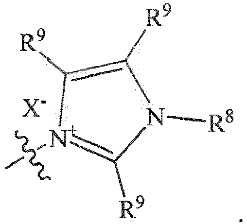
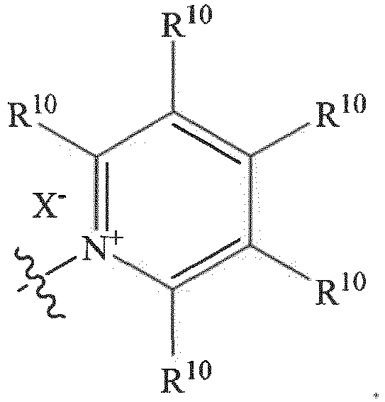
- In any of the above embodiments, each R1 may individually be a C1-C6 alkylene, C3-C16 cycloalkylene, or C3-C16 heterocycloalkylene; each R3 may individually be C1-C6 alkyl, C3-C16 cycloalkyl, or C3-C16 heterocycloalkyl; each R4 may individually be C1-C6 alkylene, C3-C16 cycloalkylene, or C3-C16 heterocycloalkylene; each R5 may individually be absent or C1-C6 alkylene, C3-C16 cycloalkylene, or C3-C16 heterocycloalkylene; and each X- may individually be an anion. Illustrative examples of anions include, but are not limited to, F-, Cl-, Br-, I-, BF4 -, PF6 -, SbF6 -, AsF6 -, ClO4 -, N(CF3SO2)2 -, C(CF3SO2)3 -, triflate (SO3CF3; trifluoromethansulfonate), N(SO2C2F5)-, BAr4 -, and a mixture of any two or more such anions, wherein Ar is an aryl or fluorinated aryl or a bis(trifluoromethyl)aryl group.
- In any embodiments of the above formulae, R6 may be -CH2-.
- Illustrative cationic polymers according to Formulae I and II include, but are not limited to those of Formulae IA-D and IIA-D:

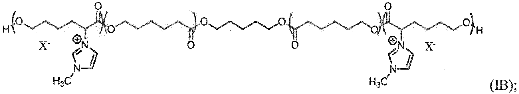

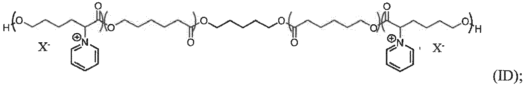


- As noted above, the cationic polymers described herein may be further cross-linked with a cross-linking agent. Illustrative cross-linking agents may include, but are not limited to di- or tri-isocyanates.
- The cationic polymers described herein have molecular weights from about 1,000 to about 10,000 Daltons. This includes, but is not limited illustrative ranges such as from about 1,000 to about 8,000 Daltons; about 1,000 to about 7,000 Daltons; about 1,000 to about 6,000 Daltons; about 1,500 to about 8,000 Daltons; about 1,500 to about 6,000 Daltons; about 1,500 to about 5,500 Daltons; about 2,000 to about 10,000 Daltons; about 2,000 to about 6,000 Daltons; about 2,000 to about 5,000 Daltons; and about 3,000 to about 6,000 Daltons.
- In another aspect, methods of preparing the transparent, ion-selective polymer membranes are provided. The methods include reacting the monomeric constituents of the polymers either neat or in a solvent such as propylene carbonate. Where a polyisocyanate is used with a diol or triol, such as for the preparation of some of the polymers described by Formulae I or II, an isocyanate:hydroxyl ratio may be from about 1.00 to about 1.10. Catalysts may be used in the reactions. For example, organotin catalysts may be used to effect the isocyanate/alcohol reaction in some embodiments. Once the polymers have been formed, they may be cast or drawn on a release liner (i.e., polyethylene terephthalate or polytetrafluoroethylene) and the solvent removed, or the polymer allowed to cure at either room, or elevated, temperature. A second release liner may be used over the polymer in a sandwich fashion, if desired.
- The present invention, thus generally described, will be understood more readily by reference to the following examples, which are provided by way of illustration and are not intended to be limiting of the present invention.
- Example 1. Preparation of pyridinium-substituted poly(vinyl formal) membrane [Reference Example]. To a reaction vessel was added 4-formyl-N-methylpyridinium tosylate (0.448 g, 1.53 mmol), 10 % (w/w) aqueous poly(vinyl alcohol) (6.00 g, 10.8 mmol OH), and deionized water (3.43 g), followed by 2-3 drops of conc. hydrochloric acid. The mixture was heated to 65 °C and stirred for 2 h, after which 37 % (w/w) aqueous formaldehyde (0.223 g, 2.75 mmol) was added. Stirring was continued at 65 °C for an additional 2 h, then the mixture was allowed to cool to ambient temperature upon standing and treated with 50 % (w/w) aqueous glutaraldehyde (0.184 g, 0.920 mmol). The mixture was stirred magnetically at ambient temperature for 15 seconds, then cast and drawn across a PET substrate with a doctor blade set to a 450 µm gap. The coating was allowed to stand at ambient temperature under laminar air flow for 22 hours, then heated in an oven at 80 °C for 30 minutes, cooled to ambient temperature, and then cut into 4.5 cm squares and separated from the PET substrate.
- Example 2. Conditioning of pyridinium-substituted poly(vinyl formal) membrane (Example 1) [Reference Example]. A 4.5 cm x 4.5 cm section of ion-exchange membrane was soaked for 2 minutes in a glass dish containing 40 % w/w aqueous sodium tetrafluoroborate and then soaked for 2 minutes in deionized water. The ion-exchange membrane was then soaked for 2 minutes in methanol and soaked for 10 minutes in a 0.500 M solution of tetraethylammonium tetrafluoroborate in propylene carbonate heated to 65 °C. The membrane was then removed from the bath and flattened between a pair of PET release liners for later use.
- Example 3. Synthesis of poly(ECH-co-THF) diol. A mixture of tetrahydrofuran (THF; 108 g, 1.49 mol), 1,5-pentanediol (6.20 mL, 59.0 mmol), and BF3-OEt2 (1.35 mL, 11.0 mmol) were cooled to 0 °C while stirring under argon, then treated dropwise with epichlorohydrin ("ECH"; 50.0 mL, 0.630 mol) over 45 minutes. Stirring was continued for an additional 16 hours, after which solid NaHCOs (3.0 g) was added and stirring continued for an additional 20 minutes. The suspension was then suction-filtered, and the filtrate was concentrated under reduced pressure (14 Torr) at 60 °C. The residue was then further dried in vacuo (50 mTorr) for an additional 20 h, affording a colorless, viscous oil (0.157 kg).
- Example 4. Synthesis of poly(ECH-co-THF) tetraol. A mixture of pentaerythritol ethoxylate (15.9 g, 59.0 mmol), tetrahydrofuran (121 mL, 1.49 mol), and BF3-OEt2 (1.35 mL, 11.0 mmol) was cooled to 0 °C while stirring under argon, then treated dropwise with epichlorohydrin (50.0 mL, 0.630 mol) added over 45 minutes. The mixture was allowed to warm to ambient temperature upon standing while stirring under Ar for an additional 22 hours, then diluted with dichloroethane (250 mL) and treated with Ca(OH)2 (6.0 g). The resulting suspension was stirred for an additional 45 minutes and then suction filtered. The filtrate was concentrated under reduced pressure (14 Torr) at 60 °C, then dried in vacuo (50 mTorr) for an additional 20 h, affording a colorless, viscous liquid (0.150 kg).
- Example 5. Synthesis of (THF-co-pyridiniumpropylene oxide ("PyPO")) diol. A mixture of poly(tetrahydrofuran-co-epichlorohydrin) diol (35.5 g) and pyridine (40.5 g, 512 mmol) was heated to 100 °C and stirred under argon for 20 hours. The resulting slurry was allowed to cool to 65 °C upon standing and then concentrated under reduced pressure (14 Torr). The residue, upon cooling to ambient temperature, was dissolved in deionized water (125 mL) and added dropwise to a stirred 40 % w/w solution of sodium tetrafluoroborate (NaBF4) in water (350 mL), during which a tan semi-solid precipitated. The supernatant was decanted, and the precipitate washed several times with deionized water (3 x 75 mL), then resuspended portionwise in dichloroethane (3 x 100 mL) and suction-filtered. The filtrate was then concentrated under reduced pressure (14 Torr) at 60 °C and the residue further dried in vacuo (50 mTorr), affording a viscous amber oil (31.2 g).
- Example 6. Synthesis of (THF-co-PyPO) tetraol. A mixture of poly(tetrahydrofuran-co-epichlorohydrin) diol (50.0 g) and pyridine (50.0 g, 632 mmol) was heated to 100 °C and stirred under argon for 20 h. The resulting slurry was allowed to cool to 65 °C upon standing and then concentrated under reduced pressure (14 Torr). The residue, upon cooling to ambient temperature, was dissolved in deionized water (200 mL) and added dropwise to a stirred 40 % w/w solution of NaBF4 in water (500 mL), during which a tan semi-solid precipitated. The supernatant was decanted, and the precipitate washed several times with deionized water (3 x 125 mL), then dissolved in dichloroethane (3 x 200 mL) and suction-filtered. The filtrate was then concentrated under reduced pressure (14 Torr) at 60 °C and the residue further dried in vacuo (50 mTorr), affording a viscous amber oil (41.0 g).
- Example 7. Synthesis of poly(THF-co-GTMA) tetraol. A mixture of pentaerythritol ethoxylate (1.86 g, 6.88 mmol), tetrahydrofuran (14.0 mL, 172 mmol), and BF3-THF (145 µL, 1.31 mmol) was cooled to 0 °C while stirring under argon and then treated dropwise with glycidyltrimethylammonium ("GTMA") bistriflimide (30.0 g, 75.7 mmol) added over 45 minutes. The mixture was allowed to warm to ambient temperature and stirred under Ar for an additional 22 hours, then diluted with dichloroethane (25 mL) and treated with sodium carbonate (6.0 g). The resulting suspension was stirred for an additional 45 minutes, then suction-filtered. The filtrate was concentrated under reduced pressure (14 Torr) at 60 °C, then dried in vacuo (50 mTorr) for an additional 22 h, affording a colorless, viscous liquid (35.0 g).
- Example 8. Curing of poly(THF-co-PyPO) tetraol with hexamethylenediisocyanate trimer ("HDT"). A 85 % w/w polyol stock solution was prepared by dissolving poly(THF-co-PyPO) (18.0 g) in propylene carbonate (3.18 g), and an isocyanate/catalyst stock solution was prepared by mixing HDT (5.65 g) and propylene carbonate (1.00 g) with 10.0 % w/w Bu2Sn(OAc)2 in propylene carbonate (0.237 g). To each of a series of nine reaction vessels was added the polyol stock solution (2.35 g) and varying quantities of the isocyanate/catalyst stock solution in order to afford NCO:OH ratios from approx. 0.80 to 1.20 in increments of 0.05 (based on an estimated polyol molecular weight of 2,144 Da). The contents of each vial were vigorously stirred with a wooden applicator rod and then allowed to stand at ambient temperature for 18 h. All nine formulations cured to transparent, light amber monoliths.
- Example 9. Build an Electrochromic device with pyridinium-substituted poly(vinyl formal) membrane [Reference Example]. Anodic gel: to a 20 mL scintillation vial were added tetraethylammonium tetrafluoroborate (Et4NBF4)(0.109 g, 0.502 mmol), glass spacer beads (250 µm, 0.300 g), and propylene carbonate (5.53 g). The mixture was gently agitated until the Et4NBF4 dissolved and was then purged with argon for 20 minutes. To the mixture was then added bis(triethylaminopropyl)dihydrophenazine bis(tetrafluoroborate) (0.080 g, 0.125 mmol) and the mixture was agitated to promote dissolution of the newly added compound. To the mixture was then added fumed silica (0.360 g), under argon purge, and the slurry was vigorously stirred with a wooden applicator. The vessel was flushed with argon and then capped.
- Cathodic gel: to a 20 mL scintillation vial were added Et4NBF4 (0.109 g, 0.502 mmol), glass spacer beads (250 µm, 0.300 g), and propylene carbonate (5.53 g). The mixture was gently agitated until the Et4NBF4 had dissolved and it was then purged with a stream of argon for 20 minutes. To the mixture was then added dioctylviologen bis(tetrafluoroborate) (0.070 g, 0.125 mmol) and the mixture agitated under argon purge to promote dissolution of the newly added compound. To the mixture was then added fumed silica (0.360 g), and the slurry was vigorously stirred with a wooden applicator. The vessel was flushed with argon and then capped.
- Spacer paste: to a 20 mL scintillation vial were added glass spacer beads (600 µm, 0.630 g), propylene carbonate (5.34 g), and fumed silica (0.400 g), and the slurry was vigorously stirred with a wooden applicator.
- In an N2-purged enclosure and under a positive N2 pressure, a "splat" cell was constructed using indium tin oxide ("ITO") coated 3x3 inch glass squares. Onto each of the four corners of the ITO-coated side of one piece of glass was evenly deposited a dot of spacer paste. Near the center of the glass square, on the ITO coated side, was then deposited a portion of the anodic gel. A strip of conditioned cationic acetal membrane from Example 2 was gently flattened between the dots of spacer paste and pressed against the deposited anodic gel. A portion of cathodic gel was then applied on top of the membrane and aligned with the anodic gel layer. The second piece of ITO-coated glass was placed atop the stacked assembly with the ITO coating in contact with the anodic gel. The two pieces of glass were held together, electrical contacts were made with each ITO coating independently through the use of bus clips and connector wires, and the whole device was placed in an enclosure and purged with Ar for 1 hour.
- Through the connector wires, the "splat" cell device was powered at 1.0 V in a reverse bias configuration for 1 minute, during which time the device remained colorless. The device was then powered at 1.0 V with forward bias for 10 seconds, and the device became dark where the anodic, cathodic and membrane stack resided. After 10 seconds, no further darkening was observed. The device was then left in an open-circuit configuration and observed at multiple intervals (e.g., 15 min, 30 min, 1 h, 2 h, 3 h, and 4 h after darkening). During this 4 hour period, no fading of the device was observed.
- The cationic, vinyl acetal membrane investigated led to excellent dynamic range, kinetics, and color-retention in a 3-layer electrochromic device constructed from separated cathodic and anodic chromophore gels.
- Example 10 [Reference Example]. The general description of the construction of an electrochromic device with a transparent ion exchange membrane (Example 2) embedded into the edges of a thermally cured epoxy perimeter seal, as shown in
FIG. 2 . With this device construction, glass gaskets on each side of the membrane were used to set the distance from each ITO coated glass substrate, creating the two electrochromic chambers, anodic and cathodic, with the transparent ion-selective membrane sandwiched between them. The gaps in each gasket allowed for the placement of small glass capillaries that functioned as ports for vacuum evacuation of the device and subsequent backfilling with electrochromic fluid. - Stepwise construction of the device is as follows: 1) the pre-cut glass gasket and two glass capillaries were arranged on a release liner in a lay-up jig; 2) the epoxy was dispensed around the capillaries and at the perimeter of the desired membrane location; 3) a glass filler plug was positioned inside the gasket to provide a continuous flat surface, and then a membrane was aligned with the epoxy and pressed flat; 4) epoxy was dispensed on top of the membrane and aligned with the epoxy below it; 5) the second gasket was positioned and capillary tubes were embedded as in steps 1-2 and then the epoxy pressed flat; 6) epoxy was dispensed in the same pattern on the second gasket and capillary tubes, and then an outer plate was placed over the epoxy and pressed flat; 7) epoxy seals were allowed to cure at ambient temperature overnight; 8) the assembly was removed from the jig, inverted, and replaced in the jig and the glass filler plug removed; 9) epoxy was dispensed matching the prior locations, and then the second outer plate was positioned on the epoxy and pressed flat; 10) the epoxy was allowed to cure overnight at ambient temperature. The device was then ready to be backfilled with fluid.
- An electrochromic solution was made by dissolving a cathodic material, 5.7 millimolar bis(octyl)viologen bis(tetrafluoroborate) and an anodic material, 4.05 millimolar bis(triethylaminopropyl)dihydrophenazine bis(tetrafluoroborate) with 0.5 millimolar decamethyl ferrocenium tetrafluoroborate; 0.5 millimolar decamethylferrocene, 0.10 molar tetraethylammonium tetrafluoroborate, 2.8% by weight of a copolymer of 2-hydroxyethylmethacrylate and methylacrylate (mole ratio of momomers in polymer at 1/10, respectively), 0.19% by weight methylene diphenyl diisocyanate, and 1.0 ppm of dibutyltin diacetate in a solvent, propylene carbonate. This electrochoromic solution was vacuum-filled into chambers on both sides of the membrane, and the device was plugged with a UV-curable epoxy.
- After allowing the electrochromic fluid to gel, a power supply was connected to the two ITO electrodes and the device was powered at 1.2 volts. The electrochromic device darkened quickly (20 - 30 s), then the device was held at open circuit. In open circuit, the electrochromic device retained color for greater than 24 hours. The devices cleared within approx. 30 - 45 s by placing a short across the two ITO electrodes.
- Example 11. Membrane electrochromic device on a transparent conductor/PET substrates using conditioned membrane from Example 2 [Reference Example]. Materials: cathodic based gel, anodic based gel, conditioned membrane from Example 2, and the substrates are a TCO/PET (polyethylene terephthalate) or a TCO coated on IMI (inorganic-metallic-inorganic conductive stack (7 ohms per square) on PET.
-
Component Mw Conc. Mass Percentage Octylviologen bis(tetrafluoroborate) 556.2 g/mol 32 mM 0.890 g 1.63% Decamethyl ferrocenium tetrafluoroborate 413.1 g/mol 0.5 mM 0.010 g 0.02% 22% Copolymer in PC* 19.6% 53.45455 g 98.00% Propylene carbonate (PC) 0.191 g 0.35% Dibutyltin diacetate (1% solution in PC) 10 ppm 50.42017 µL 54.545 Methylene diphenyl diisocyanate (MDI) 0.28% 0.168 g 3.08% PC 5.286545 g 60.000 g -
Component Mw Conc. Mass Percentage 5,10-dihydro-5,10-dimethylphenazine 210.3 g/mol 27 mM 0.284 g 0.52% Decamethyl ferrocene 326.3 g/mol 0.5 mM 0.008 g 0.01% 22% Copolymer in PC* 19.6% 53.45455 g 98.00% PC 0.799 g 1.46% Dibutyltin diacetate (1% solution in PC) 10 ppm 50.42017 µL 54.545 MDI 0.28% 0.168 g 3.08% PC 5.286545 g 60.000 g *Note: the copolymer in this experiment is a 1 to 10 molar ratio of 2-hydroxyethylmethacrylate and methyl acrylate, respectively, randomly polymerized. - Device Construction and Assembly: Multilayer device consisting of (general stackup): PET/TCO/Cathodic Gel/Ion Exchange Membrane/Anodic Gel/transparent conductor/PET. As used herein, PET is an abbreviation for polyethyleneterephthalate, and TCO is a transparent conductive oxide. Cathodic and anodic gel drawdown coatings were made on separate pieces of IMI (inorganic-metallic-inorganic silver stack (7 ohms per square) on PET using a doctor blade with a 200 micron gap (other stacks of layers that were employed include PET/inorganic-metallic-inorganic layer/TCO). The coatings were allowed to gel overnight at ambient temperature in a nitrogen box, after which the thickness of each gel coating was 100 microns.
- A conditioned ion exchange membrane (Example 2) was flattened atop the cathodic layer, and the anodic layer was then flattened atop the membrane. Pressure was applied with a roller to ensure good contact between the layers. Bus bars were affixed to the transparent conducting films (in some instances, devices prepared in this manner were placed between matching sheets of glass using a liquid, optically clear adhesive and a barrier sealant around the edge). Device transmission and current were measured while applying a potential of 1.2 V for 3 min, while holding the device in an open circuit configuration, and then shorting the device for 3 min.
- The device remained in the darkened state overnight (20 hours) while in an open circuit configuration. The device cleared within 3 minutes upon applying 1.2 V in reverse bias.
- Example 12. Comparison of no membrane, SpectraPor X, and Nafion 115-Li+.
- Preparation of Nafion 115-Li+ membrane. A 10 cm x 10 cm piece of
Nafion 115 was soaked in 250 mL 3% H2O2 at 80 °C for two hours. The membrane was rinsed with water then soaked in 250 mL 0.1% HCl at 80 °C for one hour then cooled to room temperature overnight. The membrane was then rinsed with water then soaked in 500 mL 2 M LiOH at 80 °C for two hours. The membrane was rinsed with water then soaked in 300 mL water and deoxygenated with bubbling argon for 16 hours. - Preparation of Spectra/Por 1 membrane. A section of Spectrum Laboratories Spectra/Por 1 (MWCO: 6-8000, 50 mm flat width) size exclusion membrane of 10 cm length was cut lengthwise to create a sheet of 10 cm x 10 cm. The membrane was soaked in 300 mL water that was changed twice over an hour of soaking. The membrane was then soaked in 300 mL water and deoxygenated with bubbling argon for 16 hours.
- Preparation of Electrolyte. A 50 mL vial was charged with 20.0 mL water that was then bubbled with argon for 30 minutes. 1,1'-bis(propyl-3-sulfonate)viologen (86 mg, 0.20 mmol), 5,10-bis(4-butanoate)phenazine bis(tetraethylammonium) (128 mg, 0.20 mmol), and lithium triflate (312 mg, 2.0 mmol) were added. The electrolyte was deoxygenated with argon for another 60 minutes.
- Preparation and Operation of EC elements. The elements were assembled in a box purged with argon to limit exposure of the electrolyte to oxygen. Each element consisted of two 7.5 cm x 7.5 cm glass electrodes each coated with half wave ITO and facing each other. The electrodes were separated by two layers of 254 µm thick skived PTFE tape for a total cell spacing of 508 µm. In the elements containing a membrane, the membrane was placed between the two layers of spacer tape. The compartment(s) were filled with the electrolyte. The elements were then powered at 1.2 V. After the three elements were fully colored, the potential was removed and the elements left at open circuit. The reference element with no membrane cleared within 7 minutes. The element with the Spectra/Por size exclusion membrane cleared after 2 hours. The element with Nafion-Li+ was still colored after >3 hours but had cleared overnight.
- While certain embodiments have been illustrated and described, it should be understood that changes and modifications can be made therein in accordance with ordinary skill in the art without departing from the technology in its broader aspects as defined in the appended claims.
- The embodiments, illustratively described herein may suitably be practiced in the absence of any element or elements, limitation or limitations, not specifically disclosed herein. Thus, for example, the terms "comprising," "including," "containing," etc. shall be read expansively and without limitation. Additionally, the terms and expressions employed herein have been used as terms of description and not of limitation, and there is no intention in the use of such terms and expressions of excluding any equivalents of the features shown and described or portions thereof, but it is recognized that various modifications are possible within the scope of the claimed technology. Additionally, the phrase "consisting essentially of" will be understood to include those elements specifically recited and those additional elements that do not materially affect the basic and novel characteristics of the claimed technology. The phrase "consisting of" excludes any element not specified.
- The present disclosure is not to be limited in terms of the particular embodiments described in this application. Functionally equivalent methods and compositions within the scope of the disclosure, in addition to those enumerated herein, will be apparent to those skilled in the art from the foregoing descriptions. The present disclosure is to be limited only by the terms of the appended claims, along with the full scope of equivalents to which such claims are entitled. It is to be understood that this disclosure is not limited to particular methods, reagents, compounds compositions or biological systems, which can of course vary. It is also to be understood that the terminology used herein is for the purpose of describing particular embodiments only, and is not intended to be limiting.
- In addition, where features or aspects of the disclosure are described in terms of Markush groups, those skilled in the art will recognize that the disclosure is also thereby described in terms of any individual member or subgroup of members of the Markush group.
- As will be understood by one skilled in the art, for any and all purposes, particularly in terms of providing a written description, all ranges disclosed herein also encompass any and all possible subranges and combinations of subranges thereof. Any listed range can be easily recognized as sufficiently describing and enabling the same range being broken down into at least equal halves, thirds, quarters, fifths, tenths, etc. As a non-limiting example, each range discussed herein can be readily broken down into a lower third, middle third and upper third, etc. As will also be understood by one skilled in the art all language such as "up to," "at least," "greater than," "less than," and the like, include the number recited and refer to ranges which can be subsequently broken down into subranges as discussed above. Finally, as will be understood by one skilled in the art, a range includes each individual member.
Claims (12)
- A cationic polymer represented by Formula I or Formula II:
 each R1 is individually alkylene, cycloalkylene, or heterocycloalkylene;R2 is H;each R4 is individually alkylene, cycloalkylene, or heterocycloalkylene;each R5 is individually absent, alkylene, cycloalkylene, or heterocycloalkylene;each R6 is individually absent or alkylene;each R7 is individually a group of formula:
 R8 is alkyl, cycloalkyl, or heterocycloalkyl;each R9 is individually H, F, Br, Cl, NO2, alkyl, cycloalkyl, alkoxy, aryl, or heteroaryl, or any two individual R9 groups may join together to form a ring which may be saturated or unsaturated;each R10 is individually H, F, Br, Cl, NO2, alkyl, cycloalkyl, alkoxy, aryl, or heteroaryl, or any two individual R10 groups may join together to form a ring which may be saturated or unsaturated;each R11 is individually H, alkyl, cycloalkyl, aryl, or heteroaryl, or any two individual R11 groups may join together to form a ring which may be saturated or unsaturated;each R13 may be individually alkyl or aryl;each X' is individually an anion;each n and p indicate a repeat unit of the polymer;each q may be individually 1, 2, or 3;individually T is individually absent, C(O), or CH2; andindividually T' is individually absent or C(O).
 - The cationic polymer of Claim 1, wherein:each R1 is individually C1-C6 alkylene, C3-C16 cycloalkylene, or C3-C16 heterocycloalkylene;R2 is H;each R4 is individually C1-C6 alkylene, C3-C16 cycloalkylene, or C3-C16 heterocycloalkylene;each R5 is individually absent, C1-C6 alkylene, C3-C16 cycloalkylene, or C3-C16 heterocycloalkylene;each X- is individually an anion; andq is 2.
- The cationic polymer of Claim 1, wherein the anion comprises F-, Cl-, Br-, I-, BF4 -, PF6 -, SbF6 -, AsF6 -, ClO4 -, SO3CF3 -, N(CF3SO2)2 -, C(CF3SO2)3 -, triflate (trifluoromethansulfonate), N(SO2C2F5)-, or BAr4 -, wherein Ar is an aryl or fluorinated aryl or a bis(trifluoromethyl)aryl group.
- The cationic polymer of Claim 1, wherein n is from 10 to 100 and p is from 2 to 50.
- The cationic polymer of Claim 1, wherein R7 is
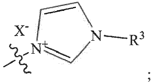 X- is an anion; andR3 is alkyl, cycloalkyl, or heterocycloalkyl.
 - The cationic polymer of Claim 1, wherein R7 is
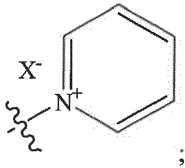
X- is an anion. - The cationic polymer of Claim 1 represented by one or more of Formulas IA-D or Formulas IIA-D:
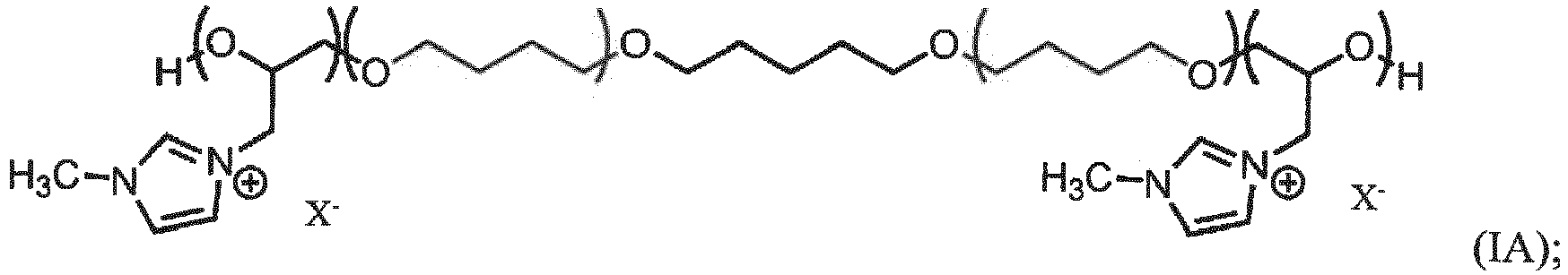

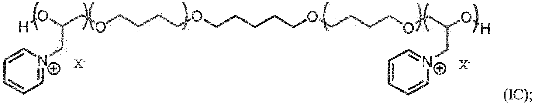
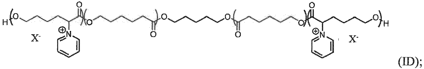
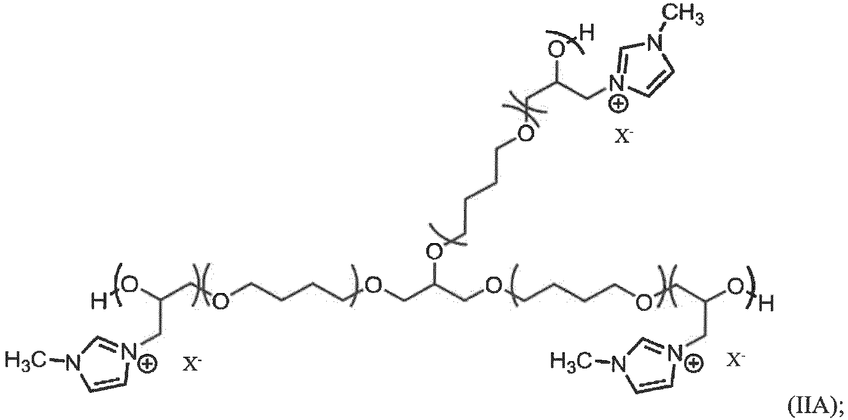
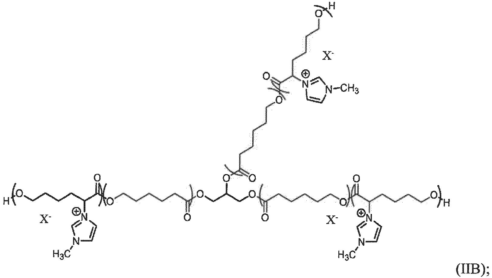

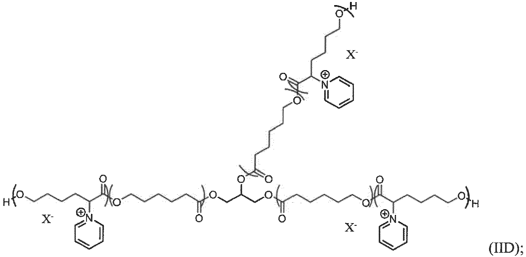
- The cationic polymer of Claim 1 which is cross-linked with a cross-linking agent.
- The cationic polymer of Claim 8, wherein the cross-linking agent is a di-isocyanate, a tri-isocyanate, a polyisocyanate, or a dialdehyde.
- An electrochromic device comprising:a cathodic compartment comprising a cathodic material;an anodic compartment comprising an anodic material; anda transparent, ion-selective membrane displaced between the cathodic compartment and the anodic compartment;wherein:
the transparent, ion-selective membrane comprises a cationic polymer of any one of claims 1 to 9. - The electrochromic device of Claim 10, wherein the cationic polymer comprises ammonium, pyridinium, imidazolium, or phosphonium functionality; and an oxygenated backbone.
- The electrochromic device of Claim 10, wherein the cationic polymer is represented by Formula I or Formula II:
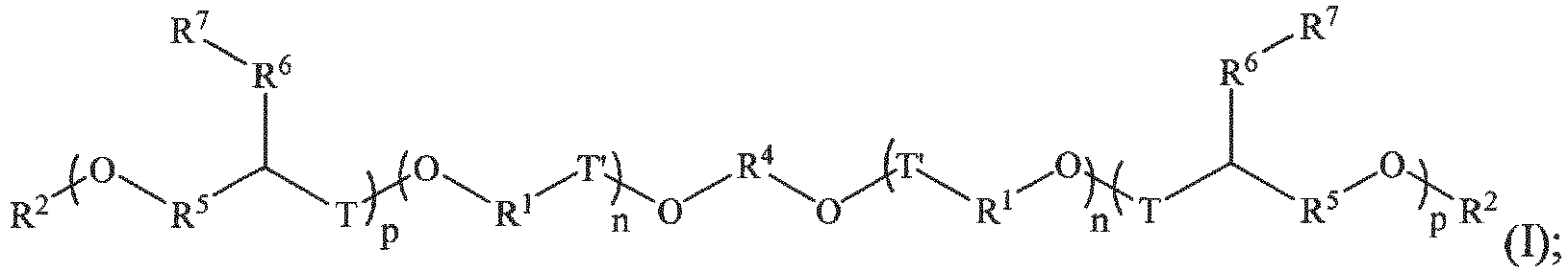
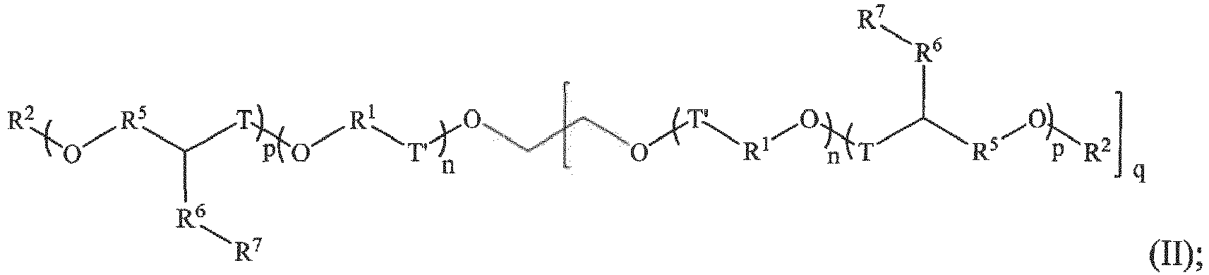 each R1 is individually alkylene, cycloalkylene, or heterocycloalkylene;R2 is H;each R4 is individually alkylene, cycloalkylene, or heterocycloalkylene;each R5 is individually absent, alkylene, cycloalkylene, or heterocycloalkylene;each R6 is individually absent or alkylene;each R7 is individually a group of formula
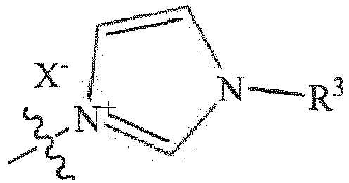
 each X- is individually an anion;each R3 is individually alkyl, cycloalkyl, or heterocycloalkyl;each n and p indicate a repeat unit of the polymer;each q may be individually 1, 2, or 3;individually T is individually absent, C(O), or CH2; andindividually T' is individually absent or C(O).
Applications Claiming Priority (2)
| Application Number | Priority Date | Filing Date | Title |
|---|---|---|---|
| US201762542570P | 2017-08-08 | 2017-08-08 | |
| PCT/US2018/045798 WO2019032695A1 (en) | 2017-08-08 | 2018-08-08 | Electro-optical device having a transparent ion exchange membrane |
Publications (3)
| Publication Number | Publication Date |
|---|---|
| EP3665528A1 EP3665528A1 (en) | 2020-06-17 |
| EP3665528A4 EP3665528A4 (en) | 2020-10-14 |
| EP3665528B1 true EP3665528B1 (en) | 2023-04-05 |
Family
ID=65271813
Family Applications (1)
| Application Number | Title | Priority Date | Filing Date |
|---|---|---|---|
| EP18844524.1A Active EP3665528B1 (en) | 2017-08-08 | 2018-08-08 | Electro-optical device having a transparent ion exchange membrane |
Country Status (6)
| Country | Link |
|---|---|
| US (1) | US10774191B2 (en) |
| EP (1) | EP3665528B1 (en) |
| JP (1) | JP6886556B2 (en) |
| KR (1) | KR102719408B1 (en) |
| CN (1) | CN110892320B (en) |
| WO (1) | WO2019032695A1 (en) |
Families Citing this family (7)
| Publication number | Priority date | Publication date | Assignee | Title |
|---|---|---|---|---|
| US9964828B2 (en) * | 2014-05-27 | 2018-05-08 | Gentex Corporation | Electrochemical energy storage devices |
| JP7293802B2 (en) * | 2019-03-28 | 2023-06-20 | 日本ゼオン株式会社 | Polyether polymer-containing composition, molded article, compression molded article and gas separation membrane |
| US20200310211A1 (en) | 2019-03-29 | 2020-10-01 | Gentex Corporation | Electro-optic sub-assemblies and assemblies having an electrochromic gel layer and methods of making |
| EP3953762B1 (en) * | 2019-04-09 | 2022-09-14 | Gentex Corporation | Low dimerizing viologen electrochromic compounds and devices |
| US11624962B2 (en) | 2019-10-02 | 2023-04-11 | Gentex Corporation | Electro-optic elements and method of forming |
| US11709407B2 (en) * | 2020-02-14 | 2023-07-25 | Gentex Corporation | Immobilized buffers in electroactive devices |
| US12474612B2 (en) | 2021-08-27 | 2025-11-18 | Gentex Corporation | Electro-optic devices made with SEBS membranes |
Family Cites Families (22)
| Publication number | Priority date | Publication date | Assignee | Title |
|---|---|---|---|---|
| US3453038A (en) | 1966-06-15 | 1969-07-01 | Du Pont | Compartmented electrochromic device |
| US4902108A (en) | 1986-03-31 | 1990-02-20 | Gentex Corporation | Single-compartment, self-erasing, solution-phase electrochromic devices, solutions for use therein, and uses thereof |
| CA2683826C (en) * | 1996-12-30 | 2013-06-11 | Hydro-Quebec | Pentacyclic anion salts or tetrazapentalene derivatives and their uses as ionic conducting materials |
| US5998617A (en) | 1997-04-02 | 1999-12-07 | Gentex Corporation | Electrochromic compounds |
| US5940201A (en) | 1997-04-02 | 1999-08-17 | Gentex Corporation | Electrochromic mirror with two thin glass elements and a gelled electrochromic medium |
| US6188505B1 (en) | 1999-08-19 | 2001-02-13 | Gentex Corporation | Color-stabilized electrochromic devices |
| US6710906B2 (en) | 1999-12-03 | 2004-03-23 | Gentex Corporation | Controlled diffusion coefficient electrochromic materials for use in electrochromic mediums and associated electrochromic devices |
| JP2002348369A (en) * | 2001-05-29 | 2002-12-04 | Kao Corp | Cationic group-containing polyalkylene oxide polymer |
| US6635194B2 (en) | 2001-08-28 | 2003-10-21 | Gentex Corporation | Electrochromic medium having a self-healing cross-linked polymer gel and associated electrochromic device |
| JP4806416B2 (en) | 2004-11-15 | 2011-11-02 | ジェンテックス コーポレイション | Electrochromic compounds and related media and devices |
| CN102057324B (en) * | 2008-04-09 | 2014-09-03 | 巴斯夫欧洲公司 | Electrochromic devices and polymer compositions |
| WO2009146202A2 (en) * | 2008-04-16 | 2009-12-03 | Segetis, Inc. | Transketalized compositions, synthesis, and applications |
| US9278348B2 (en) * | 2011-03-31 | 2016-03-08 | Zeon Corporation | Polyether compound, cross-linkable composition, and electrolyte |
| CN103619951B (en) * | 2011-07-06 | 2016-11-23 | 日本瑞翁株式会社 | Compositions |
| EP2875402A4 (en) * | 2012-07-23 | 2015-11-25 | Ricoh Co Ltd | ELECTROCHROMIC DEVICE AND METHOD FOR MANUFACTURING ELECTROCHROMIC DEVICE |
| US8928966B1 (en) * | 2012-08-08 | 2015-01-06 | Gentex Corporation | Electrochromic polyelectrolyte gel medium having improved creep resistance and associated electrochromic device |
| US9357772B2 (en) * | 2013-04-09 | 2016-06-07 | International Business Machines Corporation | Antimicrobial cationic polycarbonates |
| US9964828B2 (en) | 2014-05-27 | 2018-05-08 | Gentex Corporation | Electrochemical energy storage devices |
| KR102029304B1 (en) * | 2015-03-09 | 2019-10-07 | 젠텍스 코포레이션 | Electrochemical devices with plastic substrates |
| JP6512555B2 (en) * | 2015-08-27 | 2019-05-15 | 国立研究開発法人物質・材料研究機構 | Cationic glycidyl polymer |
| JP6816490B2 (en) * | 2015-12-14 | 2021-01-20 | 日本ゼオン株式会社 | Polyester-based polymer composition |
| CN106916099A (en) * | 2015-12-25 | 2017-07-04 | 宁波祢若电子科技有限公司 | A kind of cathodic electrochromic compound in electrochromic device and preparation method thereof |
-
2018
- 2018-08-08 EP EP18844524.1A patent/EP3665528B1/en active Active
- 2018-08-08 WO PCT/US2018/045798 patent/WO2019032695A1/en not_active Ceased
- 2018-08-08 CN CN201880046695.3A patent/CN110892320B/en active Active
- 2018-08-08 JP JP2020503761A patent/JP6886556B2/en active Active
- 2018-08-08 KR KR1020207001910A patent/KR102719408B1/en active Active
- 2018-08-08 US US16/058,526 patent/US10774191B2/en active Active
Also Published As
| Publication number | Publication date |
|---|---|
| CN110892320B (en) | 2022-05-10 |
| CN110892320A (en) | 2020-03-17 |
| US10774191B2 (en) | 2020-09-15 |
| US20190048159A1 (en) | 2019-02-14 |
| KR102719408B1 (en) | 2024-10-17 |
| EP3665528A4 (en) | 2020-10-14 |
| EP3665528A1 (en) | 2020-06-17 |
| KR20200038456A (en) | 2020-04-13 |
| JP2020529625A (en) | 2020-10-08 |
| JP6886556B2 (en) | 2021-06-16 |
| WO2019032695A1 (en) | 2019-02-14 |
Similar Documents
| Publication | Publication Date | Title |
|---|---|---|
| EP3665528B1 (en) | Electro-optical device having a transparent ion exchange membrane | |
| US11708449B2 (en) | Electrochromic multi-layer devices with cross-linked ion conducting polymer | |
| EP0995786B1 (en) | Electrochromic device | |
| EP3955053B1 (en) | Method of making an ion-conductive polymer film | |
| US10464900B2 (en) | Electrochromic compounds with improved color stability in their radical states | |
| US5142406A (en) | Electrochromic optical switching device | |
| KR102017334B1 (en) | Electrochromic devices | |
| KR20010102154A (en) | Electrochromic element | |
| WO1999023531A1 (en) | Electrochromic mirror | |
| EP1113313A1 (en) | Electrochromic mirror | |
| US6285486B1 (en) | Electrochromic mirror and electrochromic devices | |
| US6532098B1 (en) | Electrochromic element | |
| EP1010741B1 (en) | Electrochromic device | |
| JP4227716B2 (en) | Electrochromic element | |
| JP2002289052A (en) | Method for producing solid polymer electrolyte | |
| JP2000235198A (en) | Electrochromic device | |
| US12474612B2 (en) | Electro-optic devices made with SEBS membranes | |
| JP2001249365A (en) | Electrochromic mirror | |
| KR20250137435A (en) | Random copolymer with excellent self-healing and ionic conductivity, ion gel composition containing the same, and electrochromic device | |
| US11230662B2 (en) | Thiol-ene formulation for electrochromic devices, device components and related methods | |
| JP2002311459A (en) | Driving method of electrochromic mirror | |
| JPH11142893A (en) | Electrochromic mirror | |
| JP2002311460A (en) | Driving method of electrochromic mirror |
Legal Events
| Date | Code | Title | Description |
|---|---|---|---|
| STAA | Information on the status of an ep patent application or granted ep patent |
Free format text: STATUS: THE INTERNATIONAL PUBLICATION HAS BEEN MADE |
|
| PUAI | Public reference made under article 153(3) epc to a published international application that has entered the european phase |
Free format text: ORIGINAL CODE: 0009012 |
|
| STAA | Information on the status of an ep patent application or granted ep patent |
Free format text: STATUS: REQUEST FOR EXAMINATION WAS MADE |
|
| 17P | Request for examination filed |
Effective date: 20200220 |
|
| AK | Designated contracting states |
Kind code of ref document: A1 Designated state(s): AL AT BE BG CH CY CZ DE DK EE ES FI FR GB GR HR HU IE IS IT LI LT LU LV MC MK MT NL NO PL PT RO RS SE SI SK SM TR |
|
| AX | Request for extension of the european patent |
Extension state: BA ME |
|
| RIC1 | Information provided on ipc code assigned before grant |
Ipc: G02F 1/15 20190101ALI20200604BHEP Ipc: C08G 65/00 20060101ALI20200604BHEP Ipc: G02F 1/153 20060101AFI20200604BHEP Ipc: C08G 63/00 20060101ALI20200604BHEP |
|
| A4 | Supplementary search report drawn up and despatched |
Effective date: 20200910 |
|
| RIC1 | Information provided on ipc code assigned before grant |
Ipc: G02F 1/15 20190101ALI20200904BHEP Ipc: C08G 63/00 20060101ALI20200904BHEP Ipc: G02F 1/153 20060101AFI20200904BHEP Ipc: C08G 65/00 20060101ALI20200904BHEP |
|
| DAV | Request for validation of the european patent (deleted) | ||
| DAX | Request for extension of the european patent (deleted) | ||
| STAA | Information on the status of an ep patent application or granted ep patent |
Free format text: STATUS: EXAMINATION IS IN PROGRESS |
|
| 17Q | First examination report despatched |
Effective date: 20201208 |
|
| GRAP | Despatch of communication of intention to grant a patent |
Free format text: ORIGINAL CODE: EPIDOSNIGR1 |
|
| STAA | Information on the status of an ep patent application or granted ep patent |
Free format text: STATUS: GRANT OF PATENT IS INTENDED |
|
| INTG | Intention to grant announced |
Effective date: 20221219 |
|
| RIN1 | Information on inventor provided before grant (corrected) |
Inventor name: BOOGAART, NATHAN P. Inventor name: DENOLF, GARRET C. Inventor name: NEMES, JOEL C. Inventor name: FRANZ, SUE F. Inventor name: KLOEPPNER, LEROY J. Inventor name: ERNO, ZACHARY B. |
|
| GRAS | Grant fee paid |
Free format text: ORIGINAL CODE: EPIDOSNIGR3 |
|
| GRAA | (expected) grant |
Free format text: ORIGINAL CODE: 0009210 |
|
| STAA | Information on the status of an ep patent application or granted ep patent |
Free format text: STATUS: THE PATENT HAS BEEN GRANTED |
|
| AK | Designated contracting states |
Kind code of ref document: B1 Designated state(s): AL AT BE BG CH CY CZ DE DK EE ES FI FR GB GR HR HU IE IS IT LI LT LU LV MC MK MT NL NO PL PT RO RS SE SI SK SM TR |
|
| REG | Reference to a national code |
Ref country code: GB Ref legal event code: FG4D |
|
| REG | Reference to a national code |
Ref country code: CH Ref legal event code: EP |
|
| REG | Reference to a national code |
Ref country code: AT Ref legal event code: REF Ref document number: 1558672 Country of ref document: AT Kind code of ref document: T Effective date: 20230415 |
|
| REG | Reference to a national code |
Ref country code: DE Ref legal event code: R096 Ref document number: 602018048171 Country of ref document: DE |
|
| REG | Reference to a national code |
Ref country code: IE Ref legal event code: FG4D |
|
| P01 | Opt-out of the competence of the unified patent court (upc) registered |
Effective date: 20230503 |
|
| REG | Reference to a national code |
Ref country code: LT Ref legal event code: MG9D |
|
| REG | Reference to a national code |
Ref country code: NL Ref legal event code: MP Effective date: 20230405 |
|
| REG | Reference to a national code |
Ref country code: AT Ref legal event code: MK05 Ref document number: 1558672 Country of ref document: AT Kind code of ref document: T Effective date: 20230405 |
|
| PG25 | Lapsed in a contracting state [announced via postgrant information from national office to epo] |
Ref country code: NL Free format text: LAPSE BECAUSE OF FAILURE TO SUBMIT A TRANSLATION OF THE DESCRIPTION OR TO PAY THE FEE WITHIN THE PRESCRIBED TIME-LIMIT Effective date: 20230405 |
|
| PG25 | Lapsed in a contracting state [announced via postgrant information from national office to epo] |
Ref country code: SE Free format text: LAPSE BECAUSE OF FAILURE TO SUBMIT A TRANSLATION OF THE DESCRIPTION OR TO PAY THE FEE WITHIN THE PRESCRIBED TIME-LIMIT Effective date: 20230405 Ref country code: PT Free format text: LAPSE BECAUSE OF FAILURE TO SUBMIT A TRANSLATION OF THE DESCRIPTION OR TO PAY THE FEE WITHIN THE PRESCRIBED TIME-LIMIT Effective date: 20230807 Ref country code: NO Free format text: LAPSE BECAUSE OF FAILURE TO SUBMIT A TRANSLATION OF THE DESCRIPTION OR TO PAY THE FEE WITHIN THE PRESCRIBED TIME-LIMIT Effective date: 20230705 Ref country code: ES Free format text: LAPSE BECAUSE OF FAILURE TO SUBMIT A TRANSLATION OF THE DESCRIPTION OR TO PAY THE FEE WITHIN THE PRESCRIBED TIME-LIMIT Effective date: 20230405 Ref country code: AT Free format text: LAPSE BECAUSE OF FAILURE TO SUBMIT A TRANSLATION OF THE DESCRIPTION OR TO PAY THE FEE WITHIN THE PRESCRIBED TIME-LIMIT Effective date: 20230405 |
|
| PG25 | Lapsed in a contracting state [announced via postgrant information from national office to epo] |
Ref country code: RS Free format text: LAPSE BECAUSE OF FAILURE TO SUBMIT A TRANSLATION OF THE DESCRIPTION OR TO PAY THE FEE WITHIN THE PRESCRIBED TIME-LIMIT Effective date: 20230405 Ref country code: PL Free format text: LAPSE BECAUSE OF FAILURE TO SUBMIT A TRANSLATION OF THE DESCRIPTION OR TO PAY THE FEE WITHIN THE PRESCRIBED TIME-LIMIT Effective date: 20230405 Ref country code: LV Free format text: LAPSE BECAUSE OF FAILURE TO SUBMIT A TRANSLATION OF THE DESCRIPTION OR TO PAY THE FEE WITHIN THE PRESCRIBED TIME-LIMIT Effective date: 20230405 Ref country code: LT Free format text: LAPSE BECAUSE OF FAILURE TO SUBMIT A TRANSLATION OF THE DESCRIPTION OR TO PAY THE FEE WITHIN THE PRESCRIBED TIME-LIMIT Effective date: 20230405 Ref country code: IS Free format text: LAPSE BECAUSE OF FAILURE TO SUBMIT A TRANSLATION OF THE DESCRIPTION OR TO PAY THE FEE WITHIN THE PRESCRIBED TIME-LIMIT Effective date: 20230805 Ref country code: HR Free format text: LAPSE BECAUSE OF FAILURE TO SUBMIT A TRANSLATION OF THE DESCRIPTION OR TO PAY THE FEE WITHIN THE PRESCRIBED TIME-LIMIT Effective date: 20230405 Ref country code: GR Free format text: LAPSE BECAUSE OF FAILURE TO SUBMIT A TRANSLATION OF THE DESCRIPTION OR TO PAY THE FEE WITHIN THE PRESCRIBED TIME-LIMIT Effective date: 20230706 Ref country code: AL Free format text: LAPSE BECAUSE OF FAILURE TO SUBMIT A TRANSLATION OF THE DESCRIPTION OR TO PAY THE FEE WITHIN THE PRESCRIBED TIME-LIMIT Effective date: 20230405 |
|
| PG25 | Lapsed in a contracting state [announced via postgrant information from national office to epo] |
Ref country code: FI Free format text: LAPSE BECAUSE OF FAILURE TO SUBMIT A TRANSLATION OF THE DESCRIPTION OR TO PAY THE FEE WITHIN THE PRESCRIBED TIME-LIMIT Effective date: 20230405 |
|
| REG | Reference to a national code |
Ref country code: DE Ref legal event code: R097 Ref document number: 602018048171 Country of ref document: DE |
|
| PG25 | Lapsed in a contracting state [announced via postgrant information from national office to epo] |
Ref country code: SK Free format text: LAPSE BECAUSE OF FAILURE TO SUBMIT A TRANSLATION OF THE DESCRIPTION OR TO PAY THE FEE WITHIN THE PRESCRIBED TIME-LIMIT Effective date: 20230405 |
|
| PG25 | Lapsed in a contracting state [announced via postgrant information from national office to epo] |
Ref country code: SM Free format text: LAPSE BECAUSE OF FAILURE TO SUBMIT A TRANSLATION OF THE DESCRIPTION OR TO PAY THE FEE WITHIN THE PRESCRIBED TIME-LIMIT Effective date: 20230405 Ref country code: SK Free format text: LAPSE BECAUSE OF FAILURE TO SUBMIT A TRANSLATION OF THE DESCRIPTION OR TO PAY THE FEE WITHIN THE PRESCRIBED TIME-LIMIT Effective date: 20230405 Ref country code: RO Free format text: LAPSE BECAUSE OF FAILURE TO SUBMIT A TRANSLATION OF THE DESCRIPTION OR TO PAY THE FEE WITHIN THE PRESCRIBED TIME-LIMIT Effective date: 20230405 Ref country code: EE Free format text: LAPSE BECAUSE OF FAILURE TO SUBMIT A TRANSLATION OF THE DESCRIPTION OR TO PAY THE FEE WITHIN THE PRESCRIBED TIME-LIMIT Effective date: 20230405 Ref country code: DK Free format text: LAPSE BECAUSE OF FAILURE TO SUBMIT A TRANSLATION OF THE DESCRIPTION OR TO PAY THE FEE WITHIN THE PRESCRIBED TIME-LIMIT Effective date: 20230405 Ref country code: CZ Free format text: LAPSE BECAUSE OF FAILURE TO SUBMIT A TRANSLATION OF THE DESCRIPTION OR TO PAY THE FEE WITHIN THE PRESCRIBED TIME-LIMIT Effective date: 20230405 |
|
| PLBE | No opposition filed within time limit |
Free format text: ORIGINAL CODE: 0009261 |
|
| STAA | Information on the status of an ep patent application or granted ep patent |
Free format text: STATUS: NO OPPOSITION FILED WITHIN TIME LIMIT |
|
| PG25 | Lapsed in a contracting state [announced via postgrant information from national office to epo] |
Ref country code: MC Free format text: LAPSE BECAUSE OF FAILURE TO SUBMIT A TRANSLATION OF THE DESCRIPTION OR TO PAY THE FEE WITHIN THE PRESCRIBED TIME-LIMIT Effective date: 20230405 |
|
| 26N | No opposition filed |
Effective date: 20240108 |
|
| REG | Reference to a national code |
Ref country code: CH Ref legal event code: PL |
|
| PG25 | Lapsed in a contracting state [announced via postgrant information from national office to epo] |
Ref country code: MC Free format text: LAPSE BECAUSE OF FAILURE TO SUBMIT A TRANSLATION OF THE DESCRIPTION OR TO PAY THE FEE WITHIN THE PRESCRIBED TIME-LIMIT Effective date: 20230405 |
|
| PG25 | Lapsed in a contracting state [announced via postgrant information from national office to epo] |
Ref country code: LU Free format text: LAPSE BECAUSE OF NON-PAYMENT OF DUE FEES Effective date: 20230808 |
|
| PG25 | Lapsed in a contracting state [announced via postgrant information from national office to epo] |
Ref country code: LU Free format text: LAPSE BECAUSE OF NON-PAYMENT OF DUE FEES Effective date: 20230808 Ref country code: CH Free format text: LAPSE BECAUSE OF NON-PAYMENT OF DUE FEES Effective date: 20230831 |
|
| PG25 | Lapsed in a contracting state [announced via postgrant information from national office to epo] |
Ref country code: SI Free format text: LAPSE BECAUSE OF FAILURE TO SUBMIT A TRANSLATION OF THE DESCRIPTION OR TO PAY THE FEE WITHIN THE PRESCRIBED TIME-LIMIT Effective date: 20230405 |
|
| REG | Reference to a national code |
Ref country code: BE Ref legal event code: MM Effective date: 20230831 |
|
| REG | Reference to a national code |
Ref country code: IE Ref legal event code: MM4A |
|
| PG25 | Lapsed in a contracting state [announced via postgrant information from national office to epo] |
Ref country code: SI Free format text: LAPSE BECAUSE OF FAILURE TO SUBMIT A TRANSLATION OF THE DESCRIPTION OR TO PAY THE FEE WITHIN THE PRESCRIBED TIME-LIMIT Effective date: 20230405 Ref country code: IT Free format text: LAPSE BECAUSE OF FAILURE TO SUBMIT A TRANSLATION OF THE DESCRIPTION OR TO PAY THE FEE WITHIN THE PRESCRIBED TIME-LIMIT Effective date: 20230405 |
|
| PG25 | Lapsed in a contracting state [announced via postgrant information from national office to epo] |
Ref country code: IE Free format text: LAPSE BECAUSE OF NON-PAYMENT OF DUE FEES Effective date: 20230808 |
|
| PG25 | Lapsed in a contracting state [announced via postgrant information from national office to epo] |
Ref country code: IE Free format text: LAPSE BECAUSE OF NON-PAYMENT OF DUE FEES Effective date: 20230808 |
|
| PG25 | Lapsed in a contracting state [announced via postgrant information from national office to epo] |
Ref country code: BE Free format text: LAPSE BECAUSE OF NON-PAYMENT OF DUE FEES Effective date: 20230831 |
|
| PG25 | Lapsed in a contracting state [announced via postgrant information from national office to epo] |
Ref country code: BG Free format text: LAPSE BECAUSE OF FAILURE TO SUBMIT A TRANSLATION OF THE DESCRIPTION OR TO PAY THE FEE WITHIN THE PRESCRIBED TIME-LIMIT Effective date: 20230405 |
|
| PG25 | Lapsed in a contracting state [announced via postgrant information from national office to epo] |
Ref country code: BG Free format text: LAPSE BECAUSE OF FAILURE TO SUBMIT A TRANSLATION OF THE DESCRIPTION OR TO PAY THE FEE WITHIN THE PRESCRIBED TIME-LIMIT Effective date: 20230405 |
|
| PG25 | Lapsed in a contracting state [announced via postgrant information from national office to epo] |
Ref country code: CY Free format text: LAPSE BECAUSE OF FAILURE TO SUBMIT A TRANSLATION OF THE DESCRIPTION OR TO PAY THE FEE WITHIN THE PRESCRIBED TIME-LIMIT; INVALID AB INITIO Effective date: 20180808 |
|
| PG25 | Lapsed in a contracting state [announced via postgrant information from national office to epo] |
Ref country code: HU Free format text: LAPSE BECAUSE OF FAILURE TO SUBMIT A TRANSLATION OF THE DESCRIPTION OR TO PAY THE FEE WITHIN THE PRESCRIBED TIME-LIMIT; INVALID AB INITIO Effective date: 20180808 |
|
| PGFP | Annual fee paid to national office [announced via postgrant information from national office to epo] |
Ref country code: DE Payment date: 20250724 Year of fee payment: 8 |
|
| PGFP | Annual fee paid to national office [announced via postgrant information from national office to epo] |
Ref country code: GB Payment date: 20250725 Year of fee payment: 8 |
|
| PGFP | Annual fee paid to national office [announced via postgrant information from national office to epo] |
Ref country code: FR Payment date: 20250725 Year of fee payment: 8 |
|
| PG25 | Lapsed in a contracting state [announced via postgrant information from national office to epo] |
Ref country code: TR Free format text: LAPSE BECAUSE OF FAILURE TO SUBMIT A TRANSLATION OF THE DESCRIPTION OR TO PAY THE FEE WITHIN THE PRESCRIBED TIME-LIMIT Effective date: 20230405 |