EP3614526B1 - Method and network system for power management - Google Patents
Method and network system for power management Download PDFInfo
- Publication number
- EP3614526B1 EP3614526B1 EP19192644.3A EP19192644A EP3614526B1 EP 3614526 B1 EP3614526 B1 EP 3614526B1 EP 19192644 A EP19192644 A EP 19192644A EP 3614526 B1 EP3614526 B1 EP 3614526B1
- Authority
- EP
- European Patent Office
- Prior art keywords
- pdu
- power
- network
- mdus
- nodes
- Prior art date
- Legal status (The legal status is an assumption and is not a legal conclusion. Google has not performed a legal analysis and makes no representation as to the accuracy of the status listed.)
- Active
Links
Images


Classifications
-
- H—ELECTRICITY
- H02—GENERATION; CONVERSION OR DISTRIBUTION OF ELECTRIC POWER
- H02J—CIRCUIT ARRANGEMENTS OR SYSTEMS FOR SUPPLYING OR DISTRIBUTING ELECTRIC POWER; SYSTEMS FOR STORING ELECTRIC ENERGY
- H02J9/00—Circuit arrangements for emergency or stand-by power supply, e.g. for emergency lighting
- H02J9/04—Circuit arrangements for emergency or stand-by power supply, e.g. for emergency lighting in which the distribution system is disconnected from the normal source and connected to a standby source
- H02J9/06—Circuit arrangements for emergency or stand-by power supply, e.g. for emergency lighting in which the distribution system is disconnected from the normal source and connected to a standby source with automatic change-over, e.g. UPS systems
- H02J9/062—Circuit arrangements for emergency or stand-by power supply, e.g. for emergency lighting in which the distribution system is disconnected from the normal source and connected to a standby source with automatic change-over, e.g. UPS systems for AC powered loads
-
- H—ELECTRICITY
- H04—ELECTRIC COMMUNICATION TECHNIQUE
- H04L—TRANSMISSION OF DIGITAL INFORMATION, e.g. TELEGRAPHIC COMMUNICATION
- H04L12/00—Data switching networks
- H04L12/02—Details
- H04L12/10—Current supply arrangements
-
- H02J13/13—
-
- H02J13/14—
-
- H—ELECTRICITY
- H02—GENERATION; CONVERSION OR DISTRIBUTION OF ELECTRIC POWER
- H02J—CIRCUIT ARRANGEMENTS OR SYSTEMS FOR SUPPLYING OR DISTRIBUTING ELECTRIC POWER; SYSTEMS FOR STORING ELECTRIC ENERGY
- H02J3/00—Circuit arrangements for AC mains or AC distribution networks
- H02J3/12—Circuit arrangements for AC mains or AC distribution networks for adjusting voltage in AC networks by changing a characteristic of the network load
- H02J3/14—Circuit arrangements for AC mains or AC distribution networks for adjusting voltage in AC networks by changing a characteristic of the network load by switching loads on to, or off from, network, e.g. progressively balanced loading
-
- H—ELECTRICITY
- H04—ELECTRIC COMMUNICATION TECHNIQUE
- H04L—TRANSMISSION OF DIGITAL INFORMATION, e.g. TELEGRAPHIC COMMUNICATION
- H04L12/00—Data switching networks
- H04L12/02—Details
- H04L12/12—Arrangements for remote connection or disconnection of substations or of equipment thereof
-
- H—ELECTRICITY
- H04—ELECTRIC COMMUNICATION TECHNIQUE
- H04L—TRANSMISSION OF DIGITAL INFORMATION, e.g. TELEGRAPHIC COMMUNICATION
- H04L41/00—Arrangements for maintenance, administration or management of data switching networks, e.g. of packet switching networks
- H04L41/14—Network analysis or design
-
- H—ELECTRICITY
- H04—ELECTRIC COMMUNICATION TECHNIQUE
- H04L—TRANSMISSION OF DIGITAL INFORMATION, e.g. TELEGRAPHIC COMMUNICATION
- H04L43/00—Arrangements for monitoring or testing data switching networks
- H04L43/04—Processing captured monitoring data, e.g. for logfile generation
- H04L43/045—Processing captured monitoring data, e.g. for logfile generation for graphical visualisation of monitoring data
-
- H—ELECTRICITY
- H04—ELECTRIC COMMUNICATION TECHNIQUE
- H04L—TRANSMISSION OF DIGITAL INFORMATION, e.g. TELEGRAPHIC COMMUNICATION
- H04L43/00—Arrangements for monitoring or testing data switching networks
- H04L43/08—Monitoring or testing based on specific metrics, e.g. QoS, energy consumption or environmental parameters
-
- H02J2105/12—
-
- Y—GENERAL TAGGING OF NEW TECHNOLOGICAL DEVELOPMENTS; GENERAL TAGGING OF CROSS-SECTIONAL TECHNOLOGIES SPANNING OVER SEVERAL SECTIONS OF THE IPC; TECHNICAL SUBJECTS COVERED BY FORMER USPC CROSS-REFERENCE ART COLLECTIONS [XRACs] AND DIGESTS
- Y02—TECHNOLOGIES OR APPLICATIONS FOR MITIGATION OR ADAPTATION AGAINST CLIMATE CHANGE
- Y02B—CLIMATE CHANGE MITIGATION TECHNOLOGIES RELATED TO BUILDINGS, e.g. HOUSING, HOUSE APPLIANCES OR RELATED END-USER APPLICATIONS
- Y02B70/00—Technologies for an efficient end-user side electric power management and consumption
- Y02B70/30—Systems integrating technologies related to power network operation and communication or information technologies for improving the carbon footprint of the management of residential or tertiary loads, i.e. smart grids as climate change mitigation technology in the buildings sector, including also the last stages of power distribution and the control, monitoring or operating management systems at local level
- Y02B70/3225—Demand response systems, e.g. load shedding, peak shaving
-
- Y—GENERAL TAGGING OF NEW TECHNOLOGICAL DEVELOPMENTS; GENERAL TAGGING OF CROSS-SECTIONAL TECHNOLOGIES SPANNING OVER SEVERAL SECTIONS OF THE IPC; TECHNICAL SUBJECTS COVERED BY FORMER USPC CROSS-REFERENCE ART COLLECTIONS [XRACs] AND DIGESTS
- Y02—TECHNOLOGIES OR APPLICATIONS FOR MITIGATION OR ADAPTATION AGAINST CLIMATE CHANGE
- Y02B—CLIMATE CHANGE MITIGATION TECHNOLOGIES RELATED TO BUILDINGS, e.g. HOUSING, HOUSE APPLIANCES OR RELATED END-USER APPLICATIONS
- Y02B90/00—Enabling technologies or technologies with a potential or indirect contribution to GHG emissions mitigation
- Y02B90/20—Smart grids as enabling technology in buildings sector
-
- Y—GENERAL TAGGING OF NEW TECHNOLOGICAL DEVELOPMENTS; GENERAL TAGGING OF CROSS-SECTIONAL TECHNOLOGIES SPANNING OVER SEVERAL SECTIONS OF THE IPC; TECHNICAL SUBJECTS COVERED BY FORMER USPC CROSS-REFERENCE ART COLLECTIONS [XRACs] AND DIGESTS
- Y04—INFORMATION OR COMMUNICATION TECHNOLOGIES HAVING AN IMPACT ON OTHER TECHNOLOGY AREAS
- Y04S—SYSTEMS INTEGRATING TECHNOLOGIES RELATED TO POWER NETWORK OPERATION, COMMUNICATION OR INFORMATION TECHNOLOGIES FOR IMPROVING THE ELECTRICAL POWER GENERATION, TRANSMISSION, DISTRIBUTION, MANAGEMENT OR USAGE, i.e. SMART GRIDS
- Y04S20/00—Management or operation of end-user stationary applications or the last stages of power distribution; Controlling, monitoring or operating thereof
- Y04S20/12—Energy storage units, uninterruptible power supply [UPS] systems or standby or emergency generators, e.g. in the last power distribution stages
-
- Y—GENERAL TAGGING OF NEW TECHNOLOGICAL DEVELOPMENTS; GENERAL TAGGING OF CROSS-SECTIONAL TECHNOLOGIES SPANNING OVER SEVERAL SECTIONS OF THE IPC; TECHNICAL SUBJECTS COVERED BY FORMER USPC CROSS-REFERENCE ART COLLECTIONS [XRACs] AND DIGESTS
- Y04—INFORMATION OR COMMUNICATION TECHNOLOGIES HAVING AN IMPACT ON OTHER TECHNOLOGY AREAS
- Y04S—SYSTEMS INTEGRATING TECHNOLOGIES RELATED TO POWER NETWORK OPERATION, COMMUNICATION OR INFORMATION TECHNOLOGIES FOR IMPROVING THE ELECTRICAL POWER GENERATION, TRANSMISSION, DISTRIBUTION, MANAGEMENT OR USAGE, i.e. SMART GRIDS
- Y04S20/00—Management or operation of end-user stationary applications or the last stages of power distribution; Controlling, monitoring or operating thereof
- Y04S20/20—End-user application control systems
- Y04S20/222—Demand response systems, e.g. load shedding, peak shaving
-
- Y—GENERAL TAGGING OF NEW TECHNOLOGICAL DEVELOPMENTS; GENERAL TAGGING OF CROSS-SECTIONAL TECHNOLOGIES SPANNING OVER SEVERAL SECTIONS OF THE IPC; TECHNICAL SUBJECTS COVERED BY FORMER USPC CROSS-REFERENCE ART COLLECTIONS [XRACs] AND DIGESTS
- Y04—INFORMATION OR COMMUNICATION TECHNOLOGIES HAVING AN IMPACT ON OTHER TECHNOLOGY AREAS
- Y04S—SYSTEMS INTEGRATING TECHNOLOGIES RELATED TO POWER NETWORK OPERATION, COMMUNICATION OR INFORMATION TECHNOLOGIES FOR IMPROVING THE ELECTRICAL POWER GENERATION, TRANSMISSION, DISTRIBUTION, MANAGEMENT OR USAGE, i.e. SMART GRIDS
- Y04S20/00—Management or operation of end-user stationary applications or the last stages of power distribution; Controlling, monitoring or operating thereof
- Y04S20/20—End-user application control systems
- Y04S20/248—UPS systems or standby or emergency generators
Definitions
- the present disclosure is generally directed to power management. More particularly, the present disclosure relate to methods and systems for power management at a network system.
- UPS power devices or nodes
- sensitive and/or critical loads e.g., computer systems and/or other data processing systems
- An input power source such as a utility main fails
- UPS products are available, including those identified under the trade name SMART-UPS from APC by Schneider Electric, Inc. of West Kingston, RI.
- Most UPS' use batteries (or other power sources such as electronic circuitry, diesel generators or flywheels, etc.) to provide backup power to critical loads during blackout or brownout conditions (e.g., a critical window).
- the present disclosure contemplates a method for power management at a power device or node (e.g., an UPS) that includes enabling a first mode of operation at an access point (e.g., a router and/or other gateway node) connected to the power node.
- the method may further include monitoring a power state of the power node at a user interface and isolating, at the user interface, network devices connected to the access point using a first parameter.
- an end-user can disconnect, via the user interface, the isolated network devices for a set duration.
- the present disclosure contemplates a method for automatic power state management at an access point that includes configuring a critical usage window at the access point.
- the method may further include detecting, at an interface, a change in a power state of the access point during the critical usage window. After detecting the change, the power state of the access point can be adjusted for a set duration (e.g., a default time duration), at the interface, using a backup power device or node.
- the set duration correlates to network usage at variable time instants during the critical usage window.
- the present disclosure contemplates a method where a priority for groups of network devices is at least one of a low priority, medium priority, high priority, redundant, critical, and/or non-critical.
- the method may further contemplate the power state is at least one of utility mains available, utility mains unavailable, and/or utility mains unreliable.
- the present disclosure contemplates a method for reducing power expenditure at a power device or node that includes querying data associated with network devices (e.g., connected to the network at an access point) at set time intervals.
- the method may further include assigning numerical gradients or tags to the network devices based on the queried data and detecting a change in the power state of the access point.
- the power node can adjust, at an interface, the power state of the access point.
- the present disclosure contemplates a network system including an access point and a power device or node.
- the power device or node collects network data associated with network devices at set intervals, determines a power state of the access point, and provides backup power to the access point when the power state meets a first criteria and the network data meets a second criteria.
- the present disclosure contemplates a network system including a user interface in communication with an access point and a power device or node.
- the power device or node may be configured to: request a network usage status for network devices connected to the access point; classify the network devices based on the network usage status; and, when a change in a power state of the access point is detected, instruct the access point, at the user interface, to suspend power to network devices classified as non-critical for a set duration.
- the present disclosure contemplates a network system including an access point, a power device or node connected to the access point, and a user interface.
- the user interface may be configured to query a network usage status at the access point, detect a change in a power state of the access point, and, based on the queried network usage status, instruct the power node to provide backup power to the access point.
- the present disclosure contemplates methods and systems for smart, power state management at a network node (e.g., an UPS, router, metered and/or unmetered Power Distribution Unit (PDU) or Mains Distribution Unit (MDU), etc.).
- a network node e.g., an UPS, router, metered and/or unmetered Power Distribution Unit (PDU) or Mains Distribution Unit (MDU), etc.
- PDU Power Distribution Unit
- MDU Mains Distribution Unit
- a power state of the network node may be monitored at an interface.
- Various exemplary embodiments may isolate loads at the network node and/or assign numerical gradients or tags to the loads that specify a priority of the loads based on, for example, queried data.
- the network node may suspend power to or otherwise shed isolated and/or tagged loads.
- the network node may provide (or enable) machine-learning that predicts loads at the network node during the critical window and preemptively suspends power to or otherwise sheds, for example, isolated and/or tagged loads for a set duration. This enables smart, power state management at the network node by conserving power for sensitive and/or critical loads during the critical window.
- System 100 includes network devices 102A, 102B, 104A, 118 (e.g., a datacenter, server farm, remote terminal unit, computing platform, and/or other internet access device, etc.), which can use a local area network (LAN), wide area network (WAN), or internetwork (including the Internet) to communicate over communication network 114.
- the network devices 102A, 102B, 104A, 118 can be coupled to or otherwise connected to, for example, metered and/or unmetered Power Distribution Units (PDUs) and/or Mains Distribution Units (MDUs) 105A, 105B.
- System 100 further includes power nodes 106, 108, access points 110, 112, and network node 116. It is noted that the system components in FIG. 1A are not shown in any particular positioning and can be arranged as desired.
- System 100 enables smart, power state management at power nodes 106, 108 by monitoring, at a processing node and/or other cloud-based or external control module (e.g. software agent) configured to communicate with system 100, a power state (e.g., utility mains available, utility mains unavailable, utility mains unreliable, on, off, idle, active, etc.) of an input power source (e.g., utility mains), PDU/MDUs 105A, 105B, power nodes 106, 108, and/or access points 110, 112 and, when appropriate (e.g., after a predetermined wait time period), suspending power to, for example, isolated and/or tagged network loads (e.g., network devices 102A, 102B, 104A, 118, PDU/MDUs 105A, 105B, power nodes 106, 108, and/or access points 110, 112) for a set duration (e.g., milliseconds, seconds, minutes, hours, days, etc.
- Communication network 114 can be a wired and/or wireless network that uses, for example, physical and/or wireless data links to carry network data among (or between), for example, network devices 102A, 102B, 104A, 118, PDU/MDUs 105A, 105B, power nodes 106, 108, access points 110, 112, and/or network node 116.
- Network 114 can support voice, push-to-talk (PTT), broadcast video, and/or network data communications by network devices 102A, 102B, 104A, 118, PDU/MDUs 105A, 105B, power nodes 106, 108, access points 110, 112, and/or network node 116.
- PTT push-to-talk
- Wireless network protocols can include, for example, MBMS, CDMA, 1xRTT, GSM, UMTS, HSPA, EV-DO, EV-DO rev. A, 3GPP LTE, WiMAX, NFC, Bluetooth, Zigbee, 6LoWPAN, etc.
- Wired network protocols can include, for example, Ethernet, Fast Ethernet, Gigabit Ethernet, Local Talk (such as Carrier Sense Multiple Access with collision Avoidance), Token Ring, FDDI, ATM, USB, etc.
- Network node 116 can also use, for example, physical and/or wireless data links to carry network data among (or between), for example, network devices 102A, 102B, 104A, 118, PDU/MDUs 105A, 105B, power nodes 106, 108, access points 110, 112, and/or network node 116.
- Network node 116 can be a standalone computing device, computing system, or network component.
- network node 116 may include a Mobility Management Entity (MME), a Home Subscriber Server (HSS), a Policy Control and Charging Rules Function (PCRF), an Authentication, Authorization, and Accounting (AAA) node, a Rights Management Server (RMS), a Subscriber Provisioning Server (SPS), a policy server, etc.
- MME Mobility Management Entity
- HSS Home Subscriber Server
- PCRF Policy Control and Charging Rules Function
- AAA Authentication, Authorization, and Accounting
- RMS Rights Management Server
- SPS Subscriber Provisioning Server
- power node 106 can include UPS modules 106A - 106N and/or conventional power supply modules 136A - 136N.
- UPS modules 106A - 106N can be coupled (electrically or otherwise) to conventional power supply modules 136A - 136N.
- UPS modules 106A - 106N and/or conventional power supply modules 136A - 136N can be coupled to or otherwise connected to PDU/MDU 105B and/or access point 110, which may be configured as a router and/or other gateway node.
- conventional power supply modules 136A - 136N can be coupled to an input power source 138 (e.g., an external, alternating-current (AC) power source) at, for example, an input port or interface.
- an input power source 138 e.g., an external, alternating-current (AC) power source
- AC voltage received at input power source 138 can be converted into a direct-current (DC) voltage at the conventional power supply modules 136A - 136N to provide power to PDU/MDU 105B and/or access point 110 and, when necessary, to provide charging energy to battery modules 140A - 140N (or other power sources such as electronic circuitry, diesel generators or flywheels, etc.) of UPS modules 106A - 106N.
- DC direct-current
- UPS modules 106A - 106N can be coupled to conventional power supply modules 136A - 136N.
- UPS modules 106A - 106N include battery modules 140A - 140N, which can include rechargeable type batteries such as lead-acid and/or lithium-ion batteries, etc., and control module 142.
- Control module 142 contains electrical and/or electronic circuits, which may be used to control functions of the battery modules 140A - 140N of UPS modules' 106A - 106N.
- control module 142 can use the electrical and/or electronic circuits and integrated circuit components to detect a change in and/or a current power state (e.g., utility mains available, utility mains unavailable, utility mains unreliable, on, off, idle, or active, etc.) of, for example, UPS modules 106A - 106N, conventional power supply modules 136A - 136N, PDU/MDU 105B, and/or access point 110.
- UPS modules 106A - 106N UPS modules 106A - 106N
- conventional power supply modules 136A - 136N power supply modules 136A - 136N
- PDU/MDU 105B PDU/MDU 105B
- control module 142 can choose to control functions of UPS modules 106A - 106N such as, for example, charging battery modules 140A - 140N, discharging battery modules 140A - 140N, switching-off (or shutting-down) battery modules 140A - 140N, and/or causing battery modules 140A - 140N to enter an idle (or standby) mode.
- Control module 142 can receive signals from input power source 138, conventional power supply modules 136A - 136N, PDU/MDU 105B, and/or access point 110. Control module 142 can use the signals to detect loss of input power source 138, conventional power supply modules 136A - 136N, PDU/MDU 105B, and/or access point 110. When loss of input power source 138, conventional power supply modules 136A - 136N, PDU/MDU 105B, and/or access point 110 is detected, control module 142 can engage and/or control one or more functions of UPS modules 106A - 106N.
- control module 142 can engage a discharging function of battery modules 140A - 140N to provide regulated, uninterrupted power to PDU/MDU 105B and/or access point 110. Further, control module 142 can regulate voltage level(s) used to charge battery modules 140A - 140N and/or to discharge power to PDU/MDU 105B and/or access point 110.
- Multiple UPS modules 106A - 106N, battery modules 140A - 140N, and/or conventional power supply modules 136A - 136N can be installed at power node 106 to increase charge capacity, power output capacity, and/or to provide hardware redundancy.
- access points 110, 112 can be configured as wired and/or wireless routers and/or other gateway nodes. Access points 110, 112 can facilitate receipt, routing, and/or forwarding of network data. Access points 110, 112 (or other network nodes such as, for example, network devices 102A, 102B, 104A, 118, PDU/MDUs 105A, 105B, power nodes 106, 108, and/or network node 116) can query network data at set time intervals (e.g., milliseconds, seconds, minutes, hours, days, etc.).
- time intervals e.g., milliseconds, seconds, minutes, hours, days, etc.
- UPS modules 106, 108 and/or access points 110, 112 working in conjunction with PDU/MDUs 105A, 105B can isolate the network data (e.g., by performing deep packet inspection of network protocols, network data traffic, UPS module outlet setup, PDU/MDU outlet setup, etc., associated with, for example, network devices 102A, 102B, 104A, 118, PDU/MDUs 105A, 105B, power nodes 106, 108, and/or access points 110, 112), associate the isolated network data with, for example, network loads, and assign tags (e.g., low priority, medium priority, high priority, redundant, critical, non-critical, etc.) to the isolated network data and/or associated network loads based on the query.
- tags e.g., low priority, medium priority, high priority, redundant, critical, non-critical, etc.
- access points 110, 112 can generate (or assign) numerical gradients for/to network devices 102A, 102B, 104A, 118, PDU/MDUs 105A, 105B, power nodes 106, 108, network node 116, and/or at other external networks) can generate (or assign) numerical gradients for/to network devices 102A, 102B, 104A, 118, PDU/MDUs 105A, 105B, power nodes 106, 108, and/or access points 110, 112 using the assigned tags.
- Criticality of and/or redundancy of, for example, the numerical gradients can be calculated as a probability and, when the probability meets or exceeds a threshold probability, can trigger suspension of power to the network devices 102A, 102B, 104A, 118, PDU/MDUs 105A, 105B, power nodes 106, 108, and/or access points 110, 112.
- UPS modules 106, 108 On detection of a change in and/or a current power state of UPS modules 106, 108 (e.g., including UPS modules 106A - 106N, battery modules 140A - 140N, control module 142, and/or conventional power supply modules 136A - 136N), PDU/MDUs 105A, 105B, and/or access point 110, 112 and, depending on a current operating mode (e.g., manual or automatic) and/or calculated probability that meets or exceeds the probability threshold, network devices 102A, 102B, 104A, 118, PDU/MDUs 105A, 105B, power nodes 106, 108, and/or access points 110, 112 can trigger suspension of power to the isolated and/or tagged network data and/or network loads for a set duration (e.g., milliseconds, seconds, minutes, hours, days, etc.).
- a set duration e.g., milliseconds, seconds, minutes, hours, days
- network devices 102A, 102B, 104A, 118, PDU/MDUs 105A, 105B, power nodes 106, 108, and/or access points 110, 112 can be in integrated with (e.g., at a control module) a communication interface 902, user interface 904, and/or processing system 906 (as shown in FIG. 9 ).
- the interfaces 902, 904 and/or processing system 906 can receive input signals that, for example, instruct adjustment, change, and/or control of a current power state of network devices 102A, 102B, 104A, 118, PDU/MDUs 105A, 105B, power nodes 106, 108 (e.g., including UPS modules 106A - 106N, battery modules 140A - 140N, control module 142, and/or conventional power supply modules 136A - 136N), and/or access points 110, 112.
- power nodes 106, 108 e.g., including UPS modules 106A - 106N, battery modules 140A - 140N, control module 142, and/or conventional power supply modules 136A - 136N
- the interfaces 902, 904 and/or processing system 906 can further generate control signals to adjust, change, and/or control the current power state of network devices 102A, 102B, 104A, 118, PDU/MDUs 105A, 105B, power nodes 106, 108 (e.g., including UPS modules 106A - 106N, battery modules 140A - 140N, control module 142, and/or conventional power supply modules 136A - 136N), and/or access points 110, 112.
- power nodes 106, 108 e.g., including UPS modules 106A - 106N, battery modules 140A - 140N, control module 142, and/or conventional power supply modules 136A - 136N
- the interfaces 902, 904 and/or processing system 906 can generate output signals to provide haptic, tactile, and/or visual feedback of the adjusted, changed, and/or controlled power state to an end-user, network devices 102A, 102B, 104A, 118, PDU/MDUs 105A, 105B, power nodes 106, 108, and/or access points 110, 112.
- network devices 902A, 102B, 104A, 118, PDU/MDUs 105A, 105B, power nodes 106, 108, and/or access points 110, 112 can suspend power to the isolated and/or tagged network data and/or network loads using a switching-off (or shutting-down) function of battery modules 140A - 140N and/or the idle (or standby) mode of battery modules 140A - 140N and/or can instruct PDU/MDUs 105A, 105B, UPS modules 106, 108,and/or access points 110, 112 to "drop" the isolated and/or tagged network data and/or network loads.
- a switching-off (or shutting-down) function of battery modules 140A - 140N and/or the idle (or standby) mode of battery modules 140A - 140N and/or can instruct PDU/MDUs 105A, 105B, UPS modules 106, 108,and/or access points 110, 112 to "drop" the isolated and/or
- FIG. 2 a flow diagram of an exemplary method for power state management at a network node is depicted.
- the method can be implemented in the exemplary network system 100 shown in FIGS. 1A and 1B , or with any suitable network system.
- the method for power state management shown in FIG. 2 is discussed with reference to the network system 100 shown in FIGS. 1A and 1B .
- FIG. 2 depicts steps performed in a particular order for purposes of illustration, the methods should not be taken as limiting to any particular order or arrangement.
- steps of the methods can be omitted, rearranged, combined, and/or adapted in various ways.
- a critical usage window may be configured at a first node.
- a machine-learning mechanism can be enabled at network devices 102A, 102B, 104A, 118, PDU/MDUs 105A, 105B, power nodes 106, 108 (e.g., including UPS modules 106A - 106N, battery modules 140A - 140N, control module 142, and/or conventional power supply modules 136A - 136N), access points 110, 112, and/or network node 116 and used to correlate network usage at variable time instants for each of network devices 102A, 102B, 104A, 118, PDU/MDUs 105A, 105B (e.g., including PDU/MDU outlets), power nodes 106, 108 (e.g., including UPS modules 106A - 106N, battery modules 140A-140N, control module 142, and/or conventional power supply modules 136A - 136N), and/or access points 110, 1
- the machine-learning mechanism can generate unique network usage models for each of network devices 102A, 102B, 104A, 118, PDU/MDUs 105A, 105B (e.g., including PDU/MDU outlets), power nodes 106, 108, and/or access points 110, 112 at set time intervals.
- the machine-learning mechanism can generate a basic heuristic (e.g.
- a base network usage model (or pattern) for network devices 102A, 102B, 104A, 118, PDU/MDUs 105A, 105B (e.g., including PDU/MDU outlets), power nodes 106, 108, and/or access points 110, 112 such as, for example, a base network usage model that is "offline" from 1:00 a.m. until 5:00 a.m.
- the base network usage model can be updated for each of network devices 102A, 102B, 104A, 118, PDU/MDUs 105A, 105B (e.g., including PDU/MDU outlets), power nodes 106, 108, and/or access points 110, 112 using its generated unique network usage model.
- Critical usage windows can be dynamically configured for each network device 102A, 102B, 104A, 118, PDU/MDUs 105A, 105B (e.g., including PDU/MDU outlets), power node 106, 108, and/or access point 110, 112 using (or based on) its updated heuristic at, for example, network devices 102A, 102B, 104A, 118, PDU/MDUs 105A, 105B, power nodes 106, 108, access points 110, 112, and/or network node 116.
- network devices 102A, 102B, 104A, 118, PDU/MDUs 105A, 105B, power nodes 106, 108, access points 110, 112, and/or network node 116 can detect a change in and/or a current power state of, for example, PDU/MDUs 105A, 105B (e.g., including PDU/MDU outlets), power nodes 106, 108 (e.g., including UPS modules 106A - 106N, battery modules 140A - 140N, control module 142, and/or conventional power supply modules 136A - 136N) and/or access points 110, 112.
- PDU/MDUs 105A, 105B e.g., including PDU/MDU outlets
- power nodes 106, 108 e.g., including UPS modules 106A - 106N, battery modules 140A - 140N, control module 142, and/or conventional power supply modules 136A - 136N
- power nodes 106, 108 can receive (or fail to receive) signals at an interface 902, 904 and/or processing system 906 from UPS modules 106A - 106N, battery modules 140A - 140N, control module 142, conventional power supply modules 136A - 136N, PDU/MDUs 105A, 105B, and/or access points 110, 112 and use the signals (or lack thereof) to detect loss of: input power source 138, conventional power supply modules 136A - 136N, PDU/MDUs 105A, 105B (e.g., including PDU/MDU outlets), and/or access points 110, 112.
- PDU/MDUs 105A, 105B, power nodes 106, 108, and/or access points 110, 112 can engage and/or control functions of UPS modules 106A - 106N.
- PDU/MDUs 105A, 105B, power nodes 106, 108, and/or access points 110, 112 can engage a discharging function of battery modules 140A - 140N to provide regulated, uninterrupted power to network devices 102A, 102B, 104A, 118, PDU/MDUs 105A, 105B (e.g., including PDU/MDU outlets), power nodes 106, 108, and/or access points 110, 112 operating in a configured critical usage window.
- network devices 102A, 102B, 104A, 118, PDU/MDUs 105A, 105B, power nodes 106, 108, access points 110, 112, and/or network node 116 can dynamically adjust, change, and/or control a current power state of PDU/MDUs 105A, 105B (e.g., including PDU/MDU outlets), power nodes 106, 108 (e.g., including UPS modules 106A- 106N, battery modules 140A - 140N, control module 142, and/or conventional power supply modules 136A - 136N), and/or access points 110, 112 during a critical window.
- PDU/MDU outlets e.g., including UPS modules 106A- 106N, battery modules 140A - 140N, control module 142, and/or conventional power supply modules 136A - 136N
- power nodes 106, 108 detect a loss of input power source 138, conventional power supply modules 136A - 136N, PDU/MDUs 105A, 105B (e.g., including PDU/MDU outlets), and/or access point 110, 112, the power nodes 106, 108 can send a notification to alert an end-user of the detected loss (e.g., via an interface 902, 904 and/or application such as, for example, a SmartConnect Personal Application, hosted at network device 118).
- a notification e.g., via an interface 902, 904 and/or application such as, for example, a SmartConnect Personal Application, hosted at network device 118.
- the notification can include the critical usage window information for "on,” “off,” “idle,” and/or "active” network devices 102A, 102B, 104A, 118 coupled to (or in communication with) PDU/MDUs 105A, 105B (e.g., including PDU/MDU outlets), power nodes 106, 108, and/or access points 110, 112.
- the notification can further include the critical usage window information for "on,” “off,” “idle,” and/or "active” PDU/MDUs 105A, 105B (e.g., including PDU/MDU outlets) coupled to (or in communication with) network devices 102A, 102B, 104A, 118, power nodes 106, 108, and/or access points 110, 112.
- critical usage window information for "on,” “off,” “idle,” and/or “active” PDU/MDUs 105A, 105B (e.g., including PDU/MDU outlets) coupled to (or in communication with) network devices 102A, 102B, 104A, 118, power nodes 106, 108, and/or access points 110, 112.
- the end-user can change a current power state of PDU/MDUs 105A, 105B (e.g., including PDU/MDU outlets), power nodes 106, 108 (e.g., including UPS modules 106A - 106N, battery modules 140A - 140N, control module 142, and/or conventional power supply modules 136A - 136N), and/or access points 110, 112 based on the critical usage window information reported for network devices 102A, 102B, 104A, 118 and/or PDU/MDUs 105A, 105B.
- PDU/MDU outlets e.g., including PDU/MDU outlets
- power nodes 106, 108 e.g., including UPS modules 106A - 106N, battery modules 140A - 140N, control module 142, and/or conventional power supply modules 136A - 136N
- access points 110, 112 based on the critical usage window information reported for network devices 102A, 102B,
- PDU/MDUs 105A, 105B and/or access points 110, 112 are supporting (or include) "on" or “active” network devices 102A, 102B operating during a configured critical usage window
- the end-user e.g., via an interface 902, 904 and/or SmartConnect application
- PDU/MDUs 105A, 105B and/or access points 110, 112 are supporting "off' or "idle” network devices 102A, 102B, 104A and/or "on" or “active” network devices 102A, 102B, 104A operating during a non-critical usage window
- the end-user e.g., via an interface 902, 904 and/or SmartConnect application
- FIG. 3 a schematic diagram of a network system enabling a first mode of operation for power state management is depicted.
- the schematic diagram can be implemented in the exemplary network system 100 shown in FIGS. 1A and 1B , or with any suitable network system.
- the schematic diagram shown in FIG. 3 is discussed with reference to the network system 100 shown in FIGS. 1A and 1B .
- One skilled in the art, together with the description, will appreciate that various steps of the schematic diagram be omitted, rearranged, combined, and/or adapted in various ways.
- a manual mode i.e., a first mode of operation is enabled at network devices 102A, 102B, 104A, 118, PDU/MDUs 105A, 105B, power nodes 106, 108, access points 110, 112, and/or network node 116.
- Power nodes 106, 108 can include conventional power supply modules 136A - 136N and UPS modules 106A - 106N.
- Conventional power supply modules 136A - 136N can be coupled to an input power source 138 and provide charging energy to battery modules 140A - 140N of UPS modules 106A - 106N, PDU/MDUs 105A, 105B, and/or access points 110, 112 during normal conditions (e.g., conditions other than a blackout or brownout condition).
- UPS modules 106A - 106N and/or access points 110, 112 can detect a change in and/or a current power state of power nodes 106, 108 (e.g., including UPS modules 106A - 106N, battery modules 140A - 140N, control module 142, and/or conventional power supply modules 136A - 136N), PDU/MDUs 105A, 105B (e.g., including PDU/MDU outlets), and/or access points 110, 112.
- UPS modules 106A - 106N and/or access points 110, 112 can detect a change in and/or a current power state of power nodes 106, 108 (e.g., including UPS modules 106A - 106N, battery modules 140A - 140N, control module 142, and/or conventional power supply modules 136A - 136N), PDU/MDUs 105A, 105B (e.g., including PDU/MDU outlets), and/or access points 110, 112.
- UPS modules 106A - 106N receive (or fail to receive) signals from conventional power supply modules 136A - 136N, PDU/MDUs 105A, 105B (e.g., including PDU/MDU outlets), and/or access points 110, 112.
- the UPS modules 106A - 106N may use the signals (or lack thereof) to detect loss of: an input power source 138, conventional power supply modules 136A - 136N, PDU/MDUs 105A, 105B (e.g., including PDU/MDU outlets), and/or of access points 110, 112.
- PDU/MDUs 105A, 105B, power nodes 106, 108, and/or access points 110, 112 can engage and/or control functions of UPS modules 106A - 106N.
- power nodes 106, 108 can engage a discharging function of battery modules 140A - 140N to provide regulated, uninterrupted power to network devices 102A, 102B, 014A, PDU/MDUs 105A, 105B (e.g., including PDU/MDU outlets), power nodes 106, 108, and/or access points 110, 112.
- an end-user can be situated at a visitor location (e.g., a first location outside a range of PDU/MDUs 105A, 105B, power nodes 106, 108, and/or access points 110, 112).
- a visitor location e.g., a first location outside a range of PDU/MDUs 105A, 105B, power nodes 106, 108, and/or access points 110, 112).
- PDU/MDUs 105A, 105B, power nodes 106, 108 e.g., including UPS modules 106A - 106N, battery modules 140A - 140N, control module 142, and/or conventional power supply modules 136A - 136N
- access points 110, 112 can send a notification to alert the end-user of the detected loss of power (step 304) (e.g., via an interface 902, 904 and/or application such as, for example, a SmartConnect Personal Application, hosted at network device 118).
- the notification can further inform the end-user of isolated and/or tagged network data and/or loads.
- access points 110, 112 can query network data of network loads at set time intervals.
- Access points 110, 112 can isolate the network data, associate the isolated network data with network loads, and assign numerical gradients or tags to the isolated network data and/or network loads based on the query.
- the notification can include critical usage window information.
- the notification can further request that the end-user suspend power (e.g., via an interface 902, 904 and/or SmartConnect application) to PDU/MDUs 105A, 105B (e.g., including PDU/MDU outlets) and/or access points 110, 112 and supported network devices 102A, 102B, 104A using the switching-off (or shutting down) function of and/or idle (or standby) mode of battery modules 140A - 140N and/or can request that the end-user instruct power nodes 106, 108 to "drop" PDU/MDUs 105A, 105B (e.g., including PDU/MDU outlets) and/or access points 110, 112.
- PDU/MDUs 105A, 105B e.g., including PDU/MDU outlets
- the notification can request that the end-user instruct PDU/MDUs 105A, 105B (e.g., including PDU/MDU outlets) and/or access points 110, 112 to "drop" supported network devices 102A, 102B, 104A operating outside its critical usage window and/or based on assigned tags.
- network devices 102A, 102B, 104A may be supported directly at the power nodes 106, 108 and/or otherwise apart from PDU/MDUs 105A, 105B and/or access points 110, 112 using, for example, alternative power nodes, UPS modules, and/or internal battery modules configured at the network devices 102A, 102B, 104.
- the end-user can dismiss (e.g., via an interface 902, 904 and/or SmartConnect application) the notification request. For example, if the notification indicates that the isolated and/or tagged network loads are "high-priority" and/or "critical" loads and/or that the network loads are operating during a configured critical usage window, the end-user can dismiss (e.g., via an interface 902, 904 and/or SmartConnect application) the notification request and continue to provide regulated, uninterrupted power to network devices 102A, 102B, 104A, PDU/MDUs 105A, 105B (e.g., including PDU/MDU outlets), power nodes 106, 108, and/or access points 110, 112 for the duration of the configured critical usage window.
- PDU/MDUs 105A, 105B e.g., including PDU/MDU outlets
- PDU/MDUs 105A, 105B e.g., including PDU/MDU outlets
- power nodes 106, 108 e.g., including UPS modules 106A - 106N, battery modules 140A - 140N, control module 142, and/or conventional power supply modules 136A - 136N
- access points 110, 112 can send update notifications (e.g., via an interface 902, 904 and/or application) that alert the end-user of a current status (e.g., a percentage of charge remaining) of battery modules 140A - 140N.
- the end-user can configure, adjust, and/or specify default alert thresholds (e.g., at 95% of charge remaining, at 50% of charge remaining, at 25% of charge remaining, at 5% of charge remaining, etc.) for a current status of the battery modules 140A - 140N.
- Steps 306 and 308 can repeat.
- the end-user can accept (e.g., via an interface 902, 904 and/or SmartConnect application) the notification request.
- the notification indicates that the isolated and/or tagged network loads are "low-priority,” “medium priority,” “redundant,” and/or “non-critical” loads and/or that the network loads are "on,” “off,” “idle,” or “active” network devices 102A, 102B, 104A, PDU/MDUs 105A, 105B (e.g., including PDU/MDU outlets), power nodes 106, 108, and/or access points 110, 112 operating during a non-critical usage window, the end-user can accept (e.g., via an interface 902, 904 and/or SmartConnect application) the notification request.
- Acceptance of the notification request suspends power to network devices 102A, 102B, 104A, PDU/MDUs 105A, 105B (e.g., including PDU/MDU outlets), power nodes 106, 108, and/or access points 110, 112 using a switching-off (or shutting down) function of and/or idle (or standby) mode of battery modules 140A - 140N and/or "drops" supported network devices 102A, 102B, 104A and/or PDU/MDUs 105A, 105B (e.g., including PDU/MDU outlets) operating outside its critical usage window and/or assigned "low priority,” "medium priority,” “redundant,” or "non-critical" tags.
- network devices 102A, 102B, 104A, PDU/MDUs 105A, 105B, power nodes 106, 108, and/or access points 110, 112 operating in an idle (or standby) mode enter a critical usage window and/or the assigned tag is adjusted or changed to "high-priority" or "critical," an update notification can be sent (e.g., via an interface 902, 904 and/or SmartConnect application) to alert the end-user of the adjusted or changed status.
- acceptance of the notification request can include a set duration (e.g., milliseconds, seconds, minutes, hours, days, etc.) for suspension of power to network devices 102A, 102B, 104A, PDU/MDUs 105A, 105B (e.g., including PDU/MDU outlets), power nodes 106, 108, and/or access points 110, 112.
- a set duration e.g., milliseconds, seconds, minutes, hours, days, etc.
- a switching-on (or turning on) function of battery modules 140A - 140N can be automatically enabled such that power is supplied to network devices 102A, 102B, 104A, PDU/MDUs 105A, 105B (e.g., including PDU/MDU outlets), power nodes 106, 108, and/or access points 110, 112. Steps 306 and 310 can repeat.
- Steps 306 - 310 can be performed at a home location (e.g., a second location within a range of PDU/MDUs 105A, 105B, power nodes 106, 108, and/or access points 110, 112).
- the notification request includes a warning that suspending power to network devices 102A, 102B, 104A, PDU/MDUs 105A, 105B (e.g., including PDU/MDU outlets), power nodes 106, 108, and/or access points 110, 112 will cause the end-user to lose a connection to communication network 116.
- the end-user can manually cause PDU/MDUs 105A, 105B (e.g., including PDU/MDU outlets), power nodes 106, 108 (e.g., including UPS modules 106A - 106N, battery modules 140A - 140N, control module 142, and/or conventional power supply modules 136A - 136N), and/or access points 110, 112 to adjust, change, and/or control functions of UPS modules 106A - 106N such as, for example, charging battery modules 140A - 140N, discharging battery modules 140A - 140N, switching-off (or shutting-down) battery modules 140A - 140N, and/or causing battery modules 140A - 140N to enter an idle (or standby) mode at, for example, interfaces 902, 904 of a control module associated with the same.
- power nodes 106, 108 e.g., including UPS modules 106A - 106N, battery modules 140A - 140N, control module 142, and
- PDU/MDUs 105A, 105B, power nodes 106, 108, and/or access points 110, 112 can engage a discharging function of battery modules 140A - 140N such that power nodes 106, 108 self-charge (or power) even when the power nodes 106, 108 are not supporting network loads.
- power nodes 106, 108 e.g., including UPS modules 106A - 106N, battery modules 140A - 140N, control module 142, and/or conventional power supply modules 136A - 136N
- UPS modules 106A - 106N e.g., including UPS modules 106A - 106N, battery modules 140A - 140N, control module 142, and/or conventional power supply modules 136A - 136N
- input power source 138 e.g., including UPS modules 106A - 106N, battery modules 140A - 140N, control module 142, and/or conventional power supply modules 136A - 136N
- PDU/MDUs 105A, 105B, power nodes 106, 108, and/or access points 110, 112 detect a change and/or current power state of input power source 138 and/or conventional power supply modules 136A - 136N from “off' or “idle” to "on” or “active," the PDU/MDUs 105A, 105B, power nodes 106, 108, and/or access points 110, 112 can switch from using battery power (e.g., using battery modules 140A - 140N) to using input power source 138 and/or conventional power supply modules 136A - 136N.
- Conventional power supply modules 136A - 136N can provide charging energy to battery modules 140A - 140N of UPS modules 106A - 106N.
- FIG. 4 a schematic diagram of a network system enabling a second mode of operation for power state management is depicted.
- the schematic diagram can be implemented in the exemplary network system 100 shown in FIGS. 1A and 1B , or with any suitable network system.
- the schematic diagram shown in FIG. 4 is discussed with reference to the network system 100 shown in FIGS. 1A and 1B
- steps of the schematic diagram be omitted, rearranged, combined, and/or adapted in various ways.
- an automatic (i.e., a second mode) mode of operation is enabled at network devices 102A, 102B, 104A, 118, PDU/MDUs 105A, 105B, power nodes 106, 108, access points 110, 112, and/or network node 116.
- Power nodes 106, 108 can include conventional power supply modules 136A - 136N and UPS modules 106A - 106N.
- Conventional power supply modules 136A - 136N can be coupled to an input power source 138 and provide charging energy to PDU/MDUs 105A, 105B (e.g., including PDU/MDU outlets), battery modules 140A - 140N of UPS modules 106A - 106N, and/or access points 110, 112 during normal conditions.
- PDU/MDUs 105A, 105B e.g., including PDU/MDU outlets
- battery modules 140A - 140N of UPS modules 106A - 106N e.g., including PDU/MDU outlets
- access points 110, 112 e.g., access points 110, 112 during normal conditions.
- PDU/MDUs 105A, 105B, UPS modules 106A - 106N, and/or access points 110, 112 can detect a change in and/or a current power state of PDU/MDUs 105A, 105B (e.g., including PDU/MDU outlets), power nodes 106, 108 (e.g., including UPS modules 106A - 106N, battery modules 140A - 140N, control module 142, and/or conventional power supply modules 136A - 136N), and/or access points 110, 112.
- PDU/MDUs 105A, 105B e.g., including PDU/MDU outlets
- power nodes 106, 108 e.g., including UPS modules 106A - 106N, battery modules 140A - 140N, control module 142, and/or conventional power supply modules 136A - 136N
- UPS modules 106A - 106N receive (or fail to receive) signals from PDU/MDUs 105A, 105B, conventional power supply modules 136A - 136N, and/or access points 110, 112.
- the UPS modules 106A - 106N may use the signals (or lack thereof) to detect loss of: an input power source 138, conventional power supply modules 136A - 136N, PDU/MDUs 105A, 105B (e.g., including PDU/MDU outlets), and/or access points 110, 112.
- PDU/MDUs 105A, 105B, power nodes 106, 108, and/or access points 110, 112 can engage and/or control functions of UPS modules 106A - 106N.
- PDU/MDUs 105A, 105B, power nodes 106, 108, and/or access points 110, 112 can engage a discharging function of battery modules 140A - 140N to provide regulated, uninterrupted power to network devices 102A, 102B, 104A, 118, PDU/MDUs 105A, 105B (e.g., including PDU/MDU outlets), power nodes 106, 108, and/or access points 110, 112.
- network devices 102A, 102B, 104A, 118, PDU/MDUs 105A, 105B, power nodes 106, 108, access points 110, 112, and/or network node 116 can dynamically adjust, change, and/or control a power state of PDU/MDUs 105A, 105B (e.g., including PDU/MDU outlets), power nodes 106, 108 (e.g., including UPS modules 106A - 106N, battery modules 140A - 140N, control module 142, and/or conventional power supply modules 136A - 136N), and/or access points 110, 112 during a critical window.
- PDU/MDUs 105A, 105B e.g., including PDU/MDU outlets
- power nodes 106, 108 e.g., including UPS modules 106A - 106N, battery modules 140A - 140N, control module 142, and/or conventional power supply modules 136A - 136N
- a machine-learning mechanism can be executed at processing node 900 and/or other cloud based or external control modules.
- the machine-learning mechanism can be used to correlate network usage at variable time instants for each of network devices 102A, 102B, 104A, PDU/MDUs 105A, 105B (e.g., including PDU/MDU outlets), power nodes 106, 108 (e.g., including UPS modules 106A- 106N, battery modules 140A - 140N, control module 142, and/or conventional power supply modules 136A - 136N), and/or access points 110, 112.
- PDU/MDUs 105A, 105B e.g., including PDU/MDU outlets
- power nodes 106, 108 e.g., including UPS modules 106A- 106N, battery modules 140A - 140N, control module 142, and/or conventional power supply modules 136A - 136N
- the machine-learning mechanism can generate unique network usage models for each of network devices 102A, 102B, 104A, PDU/MDUs 105A, 105B (e.g., including PDU/MDU outlets), power nodes 106, 108, and/or access points 110, 112 at set time intervals.
- the machine-learning mechanism can generate a basic heuristic (e.g.
- a base network usage model (or pattern) for network devices 102A, 102B, 104A, PDU/MDUs 105A, 105B (e.g., including PDU/MDU outlets), power nodes 106, 108, and/or access points 110, 112 such as, for example, a base network usage model that is "offline" from 1:00 a.m. until 5:00 a.m.
- the generated base network usage model can be updated for each of network devices 102A, 102B, 104A, PDU/MDUs 105A, 105B (e.g., including PDU/MDU outlets), power nodes 106, 108, and/or access points 110, 112 using its own unique network usage model. For example, based on its unique network usage model, network device 102A's base network usage model may be updated to indicate that network device 102A is "online" from 1:00 a.m. until 2:00 a.m. rather than "offline”.
- Critical usage windows can be dynamically configured for each network device 102A, 102B, 104A, 118, PDU/MDUs 105A, 105B (e.g., including PDU/MDU outlets), power node 106, 108, and/or access point 110, 112 using (or based on) its updated heuristic.
- PDU/MDUs 105A, 105B, power nodes 106, 108 e.g., including UPS modules 106A - 106N, battery modules 140A - 140N, control module 142, and/or conventional power supply modules 136A - 136N
- access points 110, 112 can send a notification to alert an end-user of the detected loss of power (steps 404 and 406) (e.g., via an interface 902, 904 and/or application such as, for example, a SmartConnect Personal Application, hosted at network device 118).
- PDU/MDUs 105A, 105B, power nodes 106, 108, and/or access points 110, 112 can evaluate (e.g., by performing deep packet inspection of network protocols, network data traffic, UPS module outlet setup, PDU/MDU outlet setup, etc., associated with, for example, network devices 102A, 102B, 104A, 118, PDU/MDUs 105A, 105B, power nodes 106, 108, and/or access points 110, 112) critical usage window information for network devices 102A, 102B, 104A, PDU/MDUs 105A, 105B (e.g., including PDU/MDU outlets), power nodes 106, 108, and/or access points 110, 112.
- critical usage window information for network devices 102A, 102B, 104A, PDU/MDUs 105A, 105B (e.g., including PDU/MDU outlets), power nodes 106, 108, and/or access points 110, 112.
- PDU/MDUs 105A, 105B, power nodes 106, 108, and/or access points 110, 112 determine, for example, that PDU/MDUs 105A, 105B and/or access points 110, 112 are supporting (or include) "on" or "active" network devices 102A, 102B, 104A operating during a configured critical usage window, PDU/MDUs 105A, 105B, power nodes 106, 108, and/or access points 110, 112 (e.g., via an interface 902, 904 and/or SmartConnect application) can alert (e.g., by sending a notification) the end-user that PDU/MDUs 105A, 105B (e.g., including PDU/MDU outlets), power nodes 106, 108 (e.g., including UPS modules 106A - 106N, battery modules 140A - 140N, control module 142, and/or conventional power supply modules 136A - 136N),
- PDU/MDUs 105A, 105B, power nodes 106, 108, and/or access points 110, 112 determine, for example, that PDU/MDUs 105A, 105B (e.g., including PDU/MDU outlets) and/or access points 110, 112 are supporting (or include) "off' or "idle" network devices 102A, 102B, 104A and/or "on" or “active” network devices 102A, 102B, 104A operating during a non-critical usage window, PDU/MDUs 105A, 105B, power nodes 106, 108, and/or access points 110, 112 (e.g., via an interface 902, 904 and/or SmartConnect application) can alert (e.g., by sending a notification) the end-user that PDU/MDUs 105A, 105B (e.g., including PDU/MDU outlets), power nodes 106, 108 (e.g.,
- the notification request can include a set duration (e.g., milliseconds, seconds, minutes, hours, days, etc.) for suspension of power to network devices 102A, 102B, 104A, PDU/MDUs 105A, 105B (e.g., including PDU/MDU outlets), power nodes 106, 108, and/or access points 110, 112.
- a switching-on (or turning on) function of battery modules 140A - 140N can be automatically enabled such that power is supplied to network devices 102A, 102B, 104A, PDU/MDUs 105A, 105B (e.g., including PDU/MDU outlets), power nodes 106, 108, and/or access points 110, 112.
- the end-user can override (e.g., via an interface 902, 904 and/or SmartConnect application) the automatic mode of operation and continue to provide regulated, uninterrupted power to network devices 102A, 102B, 104A, PDU/MDUs 105A, 105B (e.g., including PDU/MDU outlets), power nodes 106, 108, and/or access points 110, 112 regardless of the critical usage window information.
- the end-user can override (e.g., via an interface 902, 904 and/or SmartConnect application) the automatic mode of operation and continue to provide regulated, uninterrupted power to network devices 102A, 102B, 104A, PDU/MDUs 105A, 105B (e.g., including PDU/MDU outlets), power nodes 106, 108, and/or access points 110, 112 regardless of the critical usage window information.
- PDU/MDUs 105A, 105B, power nodes 106, 108, and/or access points 110, 112 can operate in conjunction with a human-aided machine learning mechanism executed at process node 900 and/or other cloud-based or external control modules to predict network usage at variable time instants for each of network devices 102A, 102B, 104A, PDU/MDUs 105A, 105B (e.g., including PDU/MDU outlets), power nodes 106, 108, and/or access points 110, 112.
- a human-aided machine learning mechanism executed at process node 900 and/or other cloud-based or external control modules to predict network usage at variable time instants for each of network devices 102A, 102B, 104A, PDU/MDUs 105A, 105B (e.g., including PDU/MDU outlets), power nodes 106, 108, and/or access points 110, 112.
- processing node 900 and/or other cloud-based or external control modules can collect network traffic data from network devices 102A, 102B, 104A, PDU/MDUs 105A, 105B (e.g., including PDU/MDU outlets), power nodes 106, 108, and/or access points 110, 112 at set time intervals (e.g., milliseconds, seconds, minutes, hours, days, etc.); the collected network traffic data can be sent to a rules engine hosted at (or that forms part of) the human-aided machine learning mechanism.
- the rules engine correlates the updated heuristics for each network device 102A, 102B, 104A, PDU/MDUs 105A, 105B (e.g., including PDU/MDU outlets), power node 106, 108, and/or access point 110, 112 with the collected information.
- the rules engine predicts a current usage window and/or current power state for network devices 102A, 102B, 104A, PDU/MDUs 105A, 105B, power nodes 106, 108 (e.g., including UPS modules 106A - 106N, battery modules 140A - 140N, control module 142, and/or conventional power supply modules 136A - 136N), and/or access points 110, 112.
- power nodes 106, 108 e.g., including UPS modules 106A - 106N, battery modules 140A - 140N, control module 142, and/or conventional power supply modules 136A - 136N
- the rules engine predicts, for example, that PDU/MDUs 105A, 105B, power nodes 106, 108, and/or access points 110, 112 are supporting (or include) "on" or “active” network devices 102A, 102B, 104A operating during a configured critical usage window
- the PDU/MDUs 105A, 105B, power nodes 106, 108, and/or access points 110, 112 can alert (e.g., by sending a notification) the end-user that the rules engine predicts that PDU/MDUs 105A, 105B, power nodes 106, 108, and/or access points 110, 112 are supporting "on” or “active” network devices 102A, 102B, 104A operating during a configured critical usage window and the PDU/MDUs 105A, 105B, power nodes 106, 108, and/or access points 110, 112 will continue to engage
- the rule engine can attempt to find patterns associated with the critical windows and/or current power states of network device 102A, 102B, 104A, PDU/MDUs 105A, 105B (e.g., including PDU/MDU outlets), power node 106, 108, and/or access point 110, 112.
- the human-aided machine learning mechanism can enable machine learning such that correct and/or incorrect predictions (e.g., whether or not the end-user accepts and/or dismisses notifications to engage and/or disengage the discharging function of battery modules 140A - 140N) can be tracked.
- the human-aided machine learning mechanism can assign weightings to predictions and update the weightings (e.g., assign an importance coefficient) based on whether or not the end-user accepts and/or dismisses an associated notification. In this manner, machine-learning can be used to predict and/or send more accurate notifications to the end-user.
- Steps 406 and 408 can be performed at a home location. If the end-user is situated at the home location, the notification includes a warning that suspending power to and/or "dropping" PDU/MDUs 105A, 105B (e.g., including PDU/MDU outlets), power nodes 106, 108, access points 110, 112, and/or supported network devices 102A, 102B, 104A will cause the end-user to lose a connection to network 116.
- PDU/MDUs 105A, 105B e.g., including PDU/MDU outlets
- the end-user can dismiss the notification and/or manually instruct (e.g., via an interface 902, 904 and/or SmartConnect application) power nodes 106, 108 continue to provide regulated, uninterrupted power to network devices 102A, 102B, 104A, PDU/MDUs 105A, 105B (e.g., including PDU/MDU outlets), power nodes 106, 108, and/or access points 110, 112 regardless of critical usage window information.
- PDU/MDUs 105A, 105B e.g., including PDU/MDU outlets
- PDU/MDUs 105A, 105B, power nodes 106, 108, and/or access points 110, 112 can automatically adjust, change, and/or control functions of UPS modules 106A - 106N such as, for example, charging battery modules 140A - 140N, discharging battery modules 140A - 140N, switching-off (or shutting-down) battery modules 140A - 140N, and/or causing battery modules 140A - 140N to enter an idle (or standby) mode.
- PDU/MDUs 105A, 105B, power nodes 106, 108, and/or access points 110, 112 can automatically engage a discharging function of battery modules 140A - 140N such that PDU/MDUs 105A, 105B, power nodes 106, 108, and/or access points 110, 112 self-charge (or power) even when the PDU/MDUs 105A, 105B, power nodes 106, 108, and/or access points 110, 112 are not supporting network loads.
- power nodes 106, 108 e.g., including UPS modules 106A - 106N, battery modules 140A - 140N, control module 142, and/or conventional power supply modules 136A - 136N
- UPS modules 106A - 106N e.g., including UPS modules 106A - 106N, battery modules 140A - 140N, control module 142, and/or conventional power supply modules 136A - 136N
- input power source 138 e.g., including UPS modules 106A - 106N, battery modules 140A - 140N, control module 142, and/or conventional power supply modules 136A - 136N
- power nodes 106, 108, and/or access points 110, 112 detect a change and/or current power state of input power source 138 and/or conventional power supply modules 136A - 136N from “off' or “idle” to "on” or “active," the power nodes 106, 108 can automatically switch from using battery power (e.g., using battery modules 140A - 140N) to using input power source 138 and/or conventional power supply modules 136A - 136N.
- Conventional power supply modules 136A - 136N can provide charging energy to battery modules 140A - 140N of UPS modules 106A - 106N.
- FIG. 5 a flow diagram of an exemplary method for power state management at a network node is depicted.
- the method can be enabled in the exemplary network system 100 shown in FIGS. 1A and 1B , or with any suitable network system.
- the method for power state management shown in FIG. 5 is discussed with reference to the network system 100 shown in FIGS. 1A and 1B .
- FIG. 5 depicts steps performed in a particular order for purposes of illustration, the methods should not be taken as limiting to any particular order or arrangement.
- steps of the methods can be omitted, rearranged, combined, and/or adapted in various ways.
- a first mode of operation may be enabled at a first node and a power state of a power node may be monitored.
- a manual and/or automatic mode of operation can be enabled at network devices 102A, 102B, 104A, 118, PDU/MDUs 105A, 105B (e.g., including PDU/MDU outlets), power nodes 106, 108, access points 110, 112, and/or network node 116.
- PDU/MDUs 105A, 105B, UPS modules 106A - 106N, and/or access points 110, 112 can monitor a current power state of PDU/MDUs 105A, 105B (e.g., including PDU/MDU outlets), power nodes 106, 108 (e.g., including UPS modules 106A - 106N, battery modules 140A - 140N, control module 142, and/or conventional power supply modules 136A- 136N), and/or access points 110, 112.
- PDU/MDUs 105A, 105B e.g., including PDU/MDU outlets
- power nodes 106, 108 e.g., including UPS modules 106A - 106N, battery modules 140A - 140N, control module 142, and/or conventional power supply modules 136A- 136N
- one or more network devices connected to the first node can be isolated.
- power nodes 106, 108 e.g., including UPS modules 106A - 106N, battery modules 140A - 140N, control module 142, and/or conventional power supply modules 136A - 136N
- access points 110, 112 can query network data of network loads at set time intervals.
- Access points 110, 112 can isolate network data of network loads that meet a set criteria.
- PDU/MDUs 105A, 105B, UPS modules 106A - 106N, and/or access points 110, 112 can detect a change in the current power state of PDU/MDUs 105A, 105B (e.g., including PDU/MDU outlets), power nodes 106, 108 (e.g., including UPS modules 106A- 106N, battery modules 140A - 140N, control module 142, and/or conventional power supply modules 136A - 136N), and/or access points 110, 112.
- PDU/MDUs 105A, 105B e.g., including PDU/MDU outlets
- power nodes 106, 108 e.g., including UPS modules 106A- 106N, battery modules 140A - 140N, control module 142, and/or conventional power supply modules 136A - 136N
- UPS modules 106A - 106N can receive (or fail to receive) signals from conventional power supply modules 136A - 136N, PDU/MDUs 105A, 105B (e.g., including PDU/MDU outlets), and/or access points 110, 112.
- the UPS modules 106A - 106N may use the signals (or lack thereof) to detect loss of: an input power source 138, conventional supply modules 136A - 136N, PDU/MDUs 105A, 105B (e.g., including PDU/MDU outlets), and/or of access points 110, 112.
- power nodes 106, 108 can engage a discharging function of battery modules 140A - 140N to provide regulated, uninterrupted power to network devices 102A, 102B, 104A, PDU/MDUs 105A, 105B (e.g., including PDU/MDU outlets), power nodes 106, 108, and/or access points 110, 112.
- the end-user and/or the power nodes 106, 108 can suspend power to PDU/MDUs 105A, 105B (e.g., including PDU/MDU outlets) and/or access points 110, 112 and supported network devices 102A, 102B, 104A whose isolated network data meets the set criteria using the switching-off (or shutting down) function of and/or idle (or standby) mode of battery modules 140A - 140N and/or can instruct PDU/MDUs 105A, 105B (e.g., including PDU/MDU outlets) and/or access points 110, 112 to "drop" supported network devices 102A, 102B, 104A whose isolated network data meets the set criteria.
- PDU/MDUs 105A, 105B e.g., including PDU/MDU outlets
- access points 110, 112 e.g., including PDU/MDU outlets
- FIG. 6 a flow chart diagram depicting methods for power state management is depicted.
- the schematic diagram can be enabled in the exemplary network system 100 shown in FIGS. 1A and 1B , or with any suitable network system.
- the flow chart diagram shown in FIG. 6 is discussed with reference to the network system 100 shown in FIGS. 1A and 1B
- steps of the schematic diagram be omitted, rearranged, combined, and/or adapted in various ways.
- PDU/MDUs 105A, 105B, power nodes 106, 108 e.g., including UPS modules 106A - 106N, battery modules 140A - 140N, control module 142, and/or conventional power supply modules 136A - 136N
- access points 110, 112 monitor a power state of PDU/MDUs 105A, 105B (e.g., including PDU/MDU outlets), power nodes 106, 108, and/or access points 110, 112.
- Step 602 repeats until, at step 604, PDU/MDUs 105A, 105B, UPS modules 106A - 106N, and/or access points 110, 112 detect a change in the power state of PDU/MDUs 105A, 105B (e.g., including PDU/MDU outlets), power nodes 106, 108, and/or access points 110, 112.
- UPS modules 106A - 106N receive (or fail to receive) signals from conventional power supply modules 136A - 136N, PDU/MDUs 105A, 105B (e.g., including PDU/MDU outlets), and/or access points 110, 112.
- the UPS modules 106A - 106N may use the signals (or lack thereof) to detect loss of: an input power source 138, conventional power supply modules 136A - 136N, PDU/MDUs 105A, 105B (e.g., including PDU/MDU outlets), and/or of access points 110, 112.
- power nodes 106, 108 can engage a discharging function of battery modules 140A - 140N to provide regulated, uninterrupted power to network devices 102A, 102B, 014A, PDU/MDUs 105A, 105B (e.g., including PDU/MDU outlets), power nodes 106, 108, and/or access points 110, 112.
- an operating mode of PDU/MDUs 105A, 105B, power nodes 106, 108, and/or access points 110, 112 is determined.
- a manual and/or automatic operating mode of PDU/MDUs 105A, 105B, power nodes 106, 108, and/or access points 110, 112 can be configured at a processing node 900 and/or other cloud-based or external control module.
- an end-user can configure and/or adjust, at an interface 902, 904, the operating mode of PDU/MDUs 105A, 105B, power nodes 106, 108, and/or access points 110, 112.
- Processing node 900, other cloud-based or external control modules, PDU/MDUs 105A, 105B, power nodes 106, 108, and/or access points 110, 112 can report the updated operating mode to the end-user.
- PDU/MDUs 105A, 105B, power nodes 106, 108, and/or access points 110, 112 collect network usage information from, for example, PDU/MDUs 105A, 105B (e.g., including PDU/MDU outlets) and/or access points 110, 112 and supported network devices 102A, 102B, 104A.
- the network usage information can indicate that PDU/MDUs 105A, 105B (e.g., including PDU/MDU outlets) and/or access points 110, 112 and supported network devices 102A, 102B, 104A are "on,” “off,” “idle,” or “active.” If, at step 608, PDU/MDUs 105A, 105B (e.g., including PDU/MDU outlets) and/or access points 110, 112 and supported network devices 102A, 102B, 104A are "on” or "active,” then, at step 610, PDU/MDUs 105A, 105B, power nodes 106, 108, and/or access points 110, 112 send a notification (e.g., via an interface 902, 904 and/or application such as, for example, a SmartConnect Personal Application, hosted at network device 118) requesting that an end-user suspend power to PDU/MDUs 105A, 105B (e.g., including PDU/MDU
- the notification includes a warning that suspending power to PDU/MDUs 105A, 105B (e.g., including PDU/MDU outlets) and/or access points 110, 112 and/or supported network devices 102A, 102B, 104A will cause the PDU/MDUs 105A, 105B (e.g., including PDU/MDU outlets) and/or access points 110, 112 to lose a connection to communication network 116.
- PDU/MDUs 105A, 105B e.g., including PDU/MDU outlets
- access points 110, 112 and supported network devices 102A, 102B, 104A are "off' or "idle”
- PDU/MDUs 105A, 105B, power nodes 106, 108, and/or access points 110, 112 send a notification (e.g., via an interface 902, 904 and/or application) requesting that an end-user suspend power to PDU/MDUs 105A, 105B (e.g., including PDU/MDU outlets) and/or access points 110, 112 and supported network devices 102A, 102B, 104A using the switching-off (or shutting down) function of and/or idle (or standby) mode of battery modules 140A - 140N.
- PDU/MDUs 105A, 105B e.g., including PDU/MDU outlets
- access points 110, 112 and/or supported network devices 102A, 102B, 104A are "off" or "idle”
- the notification does not include a warning.
- the end-user can accept the request or, at step 616, the end-user can dismiss the request.
- PDU/MDUs 105A, 105B, power nodes 106, 108, and/or access points 110, 112 collect network usage information from, for example, PDU/MDUs 105A, 105B (e.g., including PDU/MDU outlets), access points 110, 112, and/or supported network devices 102A, 102B, 104A.
- the network usage information can indicate that PDU/MDUs 105A, 105B (e.g., including PDU/MDU outlets) and/or access points 110, 112 and supported network devices 102A, 102B, 104A are "on,” “off,” “idle,” or “active.” If, at step 618, PDU/MDUs 105A, 105B (e.g., including PDU/MDU outlets) and/or access points 110, 112 and/or supported network devices 102A, 102B, 104A are "on” or "active,” then, at step 610, PDU/MDUs 105A, 105B, power nodes 106, 108, and/or access points 110, 112 send a notification (e.g., via an interface 902, 904 and/or SmartConnect application) requesting that an end-user suspend power to PDU/MDUs 105A, 105B (e.g., including PDU/MDU outlets) and/or access points 110, 112 and supported network
- the notification includes a warning that suspending power to PDU/MDUs 105A, 105B (e.g., including PDU/MDU outlets) and/or access points 110, 112 and/or supported network devices 102A, 102B, 104A will cause the PDU/MDUs 105A, 105B (e.g., including PDU/MDU outlets) and/or access points 110, 112 to lose a connection to network 116.
- the end-user can accept the request or, at step 616, the end-user can dismiss the request.
- PDU/MDUs 105A, 105B e.g., including PDU/MDU outlets
- access points 110, 112 and supported network devices 102A, 102B, 104A are "off' or "idle”
- PDU/MDUs 105A, 105B, power nodes 106, 108, and/or access points 110, 112 send a notification (e.g., via an interface 902, 904 and/or SmartConnect application) alerting the end-user that PDU/MDUs 105A, 105B, power nodes 106, 108 and/or access points 110, 112 will automatically suspend power to PDU/MDUs 105A, 105B (e.g., including PDU/MDU outlets) and/or access points 110, 112 and supported network devices 102A, 102B, 104A using a switching-off (or shutting down) function of and/or idle (or standby) mode of battery modules 140
- the end-user can accept the notification.
- the end-user can dismiss the notification and instruct PDU/MDUs 105A, 105B (e.g., including PDU/MDU outlets), power nodes 106, 108, and/or access points 110, 112 to maintain a powered state.
- PDU/MDUs 105A, 105B e.g., including PDU/MDU outlets
- power nodes 106, 108, and/or access points 110, 112 to maintain a powered state.
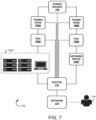
- System 700 includes network devices 702A, 702B, 718 (e.g., a datacenter, server farm, remote terminal unit, computing platform, and/or other internet access device, etc.), which can use a LAN, WAN or internetwork (including the Internet) to communicate over communication network (shown in FIG. 1 ).
- the network devices 702A, 702B, 718 can be coupled to or otherwise connected to, for example, metered and/or unmetered PDUs and/or MDUs 705A, 705B.
- System 700 further includes power nodes 706A, 706B, access point 710, network node 716, and input power source 738 (e.g., utility mains, etc.). It is noted that the system components in FIG. 7 are not shown in any particular positioning.
- System 700 enables smart, power state management at network devices 702A, 702B, 718, PDU/MDUs 705A, 705B, and/or power nodes 706A, 706B by monitoring, at a processing node and/or other cloud-based or external control module (e.g., at a central Remote Monitoring and Management (RMM) tool) configured to communicate with system 700, a power state (e.g., utility mains available, utility mains unavailable, utility mains unreliable, on, off, idle, active, artificial sleep, low-energy mode, hibernating, etc.) of the input power source 738, power nodes 706A, 706B, PDU/MDUs 705A, 705B, network devices 702A, 702B, 718, and/or access point 710 and, when appropriate (e.g., after a grace period, predetermined wait time period, etc.), suspending power to, for example, network loads (e.g., network devices 702A, 702B, 718
- power state management decisions at network devices 702A, 702B, 718, PDU/MDUs 705A, 705B, and/or power nodes 706A, 706B can be determined using startup and/or shutdown rules configured based on the power state of the input power source 738, power nodes 706A, 706B, PDU/MDUs 705A, 705B, network devices 702A, 702B, 718, and/or access point 710 and power availability.
- access point 710 can be configured as a wired and/or wireless router and/or other gateway node. Access point 710 can facilitate receipt, routing, and/or forwarding of network data. Access point 710 can query and/or monitor network data (e.g., using an RMM tool) at set time intervals (e.g., milliseconds, seconds, minutes, hours, days, etc.).
- RMM tool e.g., milliseconds, seconds, minutes, hours, days, etc.
- Access point 710 working in conjunction with power nodes 706A, 706B and/or PDU/MDUs 705A, 705B, can isolate the network data (e.g., by performing deep packet inspection of network protocols, network data traffic, PDU/MDU outlet setup, UPS module outlet setup, memory, hard-drive space, number of open files, open network connections, applications running, number of guest VMs running, etc., associated with, for example, network devices 702A, 702B, PDU/MDUs 705A, 705B, power nodes 706A, 706B, and/or access point 710) and associate the isolated network data with, for example, network loads, and assign priority tags (e.g., redundant, critical, non-critical, etc.) to the isolated network data and/or associated network loads based on the query.
- priority tags e.g., redundant, critical, non-critical, etc.
- power nodes 706A, 706B, PDU/MDUs 705A, 705B, and/or access point 710 On detection of a change in and/or a current power state of input power source 738, power nodes 706A, 706B, PDU/MDUs 705A, 705B, and/or access point 710 and, depending on a current operating mode (e.g., manual or automatic), network devices 702A, 702B, 718, PDU/MDUs 705A, 705B, power nodes 706A, 706B, and/or access point 710 can shed (or trigger suspension of power to) the isolated and/or tagged network data and/or network loads after a grace period for a set duration (e.g., milliseconds, seconds, minutes, hours, days, etc.).
- a set duration e.g., milliseconds, seconds, minutes, hours, days, etc.
- network devices 702A, 702B, 718, PDU/MDUs 705A, 705B, power nodes 706A, 706B, and/or access point 710 can be integrated with (e.g., at a control module and/or the RMM tool) a communication interface 902, user interface 904, and/or processing system 906 (as shown in FIG. 9 ).
- the interfaces 902, 904 and/or processing system 906 can receive input signals that, for example, instruct adjustment, change, and/or control of a current power state of network devices 702A, 702B, 718, PDU/MDUs 705A, 705B, power nodes 706A, 706B, and/or access point 710.
- the interfaces 902, 904 and/or processing system 906 can further generate control signals to adjust, change, and/or control the current power state of network devices 702A, 702B, 718, PDU/MDUs 705A, 705B, power nodes 706A, 706B, and/or access point 710.
- the interfaces 902, 904 and/or processing system 906 can generate output signals to provide haptic, tactile, and/or visual feedback of the adjusted, changed, and/or controlled power state to an end-user, network devices 702A, 702B, 718, PDU/MDUs 705A, 705B, power nodes 706A, 706B, and/or access point 710.
- network devices 702A, 702B, 718, PDU/MDUs 705A, 705B, power nodes 706A, 706B, and/or access point 710 can shed the isolated and/or tagged network data and/or network loads using a switching-off (or shutting-down) function of the power nodes 706A, 706B and/or the idle mode (or standby, artificial sleep, low-energy mode, hibernating mode, etc.) of the power nodes 706A, 706B and/or can instruct PDU/MDUs 705A, 705B, power nodes 706A, 706B, and/or access point 710 to "drop" the isolated and/or tagged network data and/or network loads.
- Alternate embodiments apply principles of the invention during normal runtime operation of a device, such as a UPS.
- management software may enforce an artificial sleep, on some currently unutilized equipment in order to, for example, save power.
- the management software commands power to be applied to the equipment again.
- a group of rules may be created and/or maintained which may be used to locate unneeded and/or underutilized equipment and/or apply/remove power on such equipment until needed. These rules and procedures may use the same mechanisms as described above.
- FIG. 8 a flow diagram of an exemplary method for power state management at a network node is depicted.
- the method can be implemented in the exemplary network system 100 shown in FIGS. 1A and 1B , the exemplary network system 700 shown in FIG. 7 , or with any suitable network system.
- the method for power state management shown in FIG. 8 is discussed with reference to the network system 700 shown in FIG. 7 .
- FIG. 8 depicts steps performed in a particular order for purposes of illustration, the methods should not be taken as limiting to any particular order or arrangement.
- steps of the methods can be omitted, rearranged, combined, and/or adapted in various ways.
- a priority may be configured for a group of network nodes and used to disconnect network nodes for a set duration when a power state of the power node meets a set criteria.
- multiple network devices 702A, 702B e.g., a datacenter, server farm, remote terminal unit, computing platform, and/or other internet access device, etc.
- 718 may be located at a facility (not shown) and supported by PDU/MDUs 705A, 705B, power nodes 706A, 706B, and/or access point 710.
- network devices 702A may be supported by PDU/MDU 705A and/or power node 706A and network devices 702B may be supported by PDU/MDU 706A and/or power node 706B.
- Network devices 702A can include, for example, three servers: (1) configured to run the network and/or mail server for the facility; (2) configured to manage environmental controls and/or security systems for the facility; and (3) configured to perform on-demand internal development testing for the facility.
- Network devices 702B can include, for example, five servers: (1) configured to manage a database server that hosts a website of the facility; (2) - (4) configured to host and/or manage redundant copies of the website hosted at the database server; and (5) configured distribute loads (e.g., load-balancer) across the redundant servers (2) - (4).
- loads e.g., load-balancer
- an end-user can implement a pairing process and, using an interface 902, 904 and/or SmartConnect application hosted at network devices 702A, 702B, 718, migrate a management wizard and a unique identifier to each of the servers of the network devices 702A, 702B.
- the network devices 702, 702B, 718, PDU/MDUs 705A, 705B, power nodes 706A, 706B, and/or access point 710 can validate (e.g., using a key generated based on the unique identifier, etc.) the servers of the network devices 702A, 702B.
- the servers of the network devices 702A, 702B may be added to a graphical user interface (GUI) of, for example, network device 718.
- GUI graphical user interface
- An end-user can configure a layout of the servers of the network devices 702A, 702B using the GUI.
- an end-user can create associations between the servers of the network devices 702A, 702B and PDU/MDUs 705A, 705B, power nodes 706A, 706B, and/or access point 710.
- PDU/MDUs 705A, 705B, power nodes 706A, 706B, and/or access point 710 are supporting (or include) critical servers of the network devices 702A, 702B operating during a configured critical usage window
- the end-user e.g., via an interface 902, 904 and/or SmartConnect application
- servers (1) and (2), supported by network devices 702A, and servers (4) and (8), supported by network devices 702B may be designated as critical servers.
- Server (3), supported by network devices 702A may be designated as a non-critical server and servers (5) - (7), supported by network devices 702B, may be designated as redundant servers.
- servers (1) and (2) may be assigned critical priority tags
- server (3) maybe assigned a non-critical priority tag
- servers (5) - (7) may be assigned redundant priority tags.
- an end-user can configure the servers (5) - (7) as a redundant group and specify (e.g., via an interface 902, 904 and/or SmartConnect application) that only a single server of the redundant group of servers (5) - (7) needs to be in an "on,” "idle,” and/or "active" state during a critical usage window.
- the end-user can further specify that the network data of each server in the redundant group of servers (5) - (7) be measured using, for example, CPU usage and/or a number of open connections, and that a threshold for assignment of a critical priority tag to a server (5) - (7) in the redundant group of servers be greater than, for example, 85 percent for at least one minute.
- the end-user configures a grace period for the critical, non-critical, and/or redundant group of servers such that on detection of a change in and/or current power state of network devices 702A, 702B, PDU/MDUs 705A, 705B, power nodes 706A, 706B, access point 710, and/or input power source 738 and, depending on a current operating mode (e.g., manual or automatic), network devices 702A, 702B, PDU/MDUs 705A, 705B, power nodes 706A, 706B, and/or access point 710 delays shedding of the critical, non-critical and/or redundant servers for a set duration (e.g., milliseconds, seconds, minutes, hours, days, etc.).
- a set duration e.g., milliseconds, seconds, minutes, hours, days, etc.
- network devices 702A, 702B, PDU/MDUs 705A, 705B, power nodes 706A, 706B, access point 710, and/or network node 716 can detect a change in and/or a current power state of, for example, PDU/MDUs 705A, 705B (including PDU/MDU outlets), power nodes 706A, 706B, access point 710, and/or input power source 738.
- power nodes 706A, 706B can receive (or fail to receive) signals at an interface 902, 904 and/or processing system 906 from PDU/MDUs 705A, 705B, access point 710, and/or input power source 738 and use the signals (or lack thereof) to detect loss of: input power source 738, PDU/MDUs 705A, 705B (e.g., including PDU/MDU outlets), power nodes 706A, 706B, and/or access point 710.
- PDU/MDUs 705A, 705B e.g., including PDU/MDU outlets
- PDU/MDUs 705A, 705B e.g., including PDU/MDU outlets
- power nodes 706A, 706B, and/or access point 710 can engage and/or control functions of the power nodes 706A, 706B.
- PDU/MDUs 705A, 705B, power nodes 706A, 706B, and/or access point 710 can engage a discharging function of battery modules to provide regulated, uninterrupted power to servers (1) - (8) supported by network devices 702A, 702B operating in a configured critical usage window.
- the end-user e.g., via an interface 902, 904 and/or SmartConnect application
- the end-user can instruct power nodes 706A, 706B to continue to engage the discharging function of the battery modules to provide regulated, uninterrupted power to PDU/MDUs 705A, 705B (e.g., including PDU/MDU outlets) and/or access point 710 and the servers (1), (2), (4), and (8) assigned a critical priority tag, which servers are supported network devices 702A, 702B, for a duration of the configured critical usage window.
- the end-user can instruct power nodes 706A, 706B to shed (or suspend power to) PDU/MDUs 705A, 705B (e.g., including PDU/MDU outlets) and/or access point 710 and supported servers (3) and (5) - (7) assigned non-critical and/or redundant priority tags using a switching-off (or shutting-down) function of the power nodes 706A, 706B and/or the idle mode (or standby, artificial sleep, low-energy mode, hibernating mode, etc.) and/or can instruct power nodes 706A, 706B to "drop" PDU/MDUs 705A, 705B (e.g., including PDU/MDU outlets) and/or access points 710 and the supported servers (3) and (5) - (7) until one or more of the servers (3) and (5) - (7), network devices 702A, 702B, PDU/MDUs 705A
- PDU/MDUs 705A, 705B e.g.,
- FIG. 9 illustrates an exemplary processing node 900 in a network system.
- Processing node 900 can include a communication interface 902, user interface 904, and processing system 906 in communication with communication interface 902 and user interface 904.
- Processing system 906 includes storage 908, which can comprise a disk drive, flash drive, memory circuitry, or other memory device.
- Storage 908 can store software 910, which is used in the operation of processing node 900.
- Storage 908 includes a disk drive, flash drive, data storage circuitry, or some other memory apparatus.
- Software 910 can include computer programs, firmware, or some other form of machine-readable instructions, including an operating system, utilities, drivers, network interfaces, applications, or some other type of software.
- Processing system 906 can include a microprocessor and other circuitry to retrieve and execute software 910 from storage 908.
- Processing node 900 can further include other components such as a power management unit, a control interface unit, etc., which are omitted for clarity.
- Communication interface 902 permits processing node 900 to communicate with other network elements.
- User interface 904 permits the configuration and control of the operation of processing node 900.
- processing node 900 can include network nodes 116, 716, access points 110, 112, 710, PDU/MDUs 105A, 105B, 705A, 705B, power nodes 106, 108, 706A, 706B, UPS modules 106A - 106N, battery module 140A - 140N, control module 142, and/or conventional power supply modules 136A - 136N.
- Processing node 900 can also be a component of a network element, such as a component of network nodes 116, 716, access points 110, 112, router 710, PDU/MDUs 105A, 105B, 705A, 705B, power nodes 106, 108, 706A, 706B, UPS modules 106A - 106N, battery module 140A - 140N, control module 142, and/or conventional power supply modules 136A - 136N.
- Processing node 900 can also be another network element in a network system. Further, the functionality of processing node 900 can be distributed over multiple network elements of the network system.
- the exemplary methods and systems described can be performed under the control of a processing system executing computer-readable codes embodied on a computer-readable recording medium or signals sent through a transitory medium.
- the computer-readable recording medium can be any data storage device that can store data readable by a processing system and includes both volatile and nonvolatile media, removable and non-removable media, and contemplates media readable by a database, a computer, and various other network devices.
- Examples of the computer-readable recording medium include, but are not limited to, read-only memory (ROM), random-access memory (RAM), erasable electrically programmable ROM (EEPROM), flash memory or other memory technology, holographic media or other optical disc storage, magnetic storage including magnetic tape and magnetic disk, and solid state storage devices.
- ROM read-only memory
- RAM random-access memory
- EEPROM erasable electrically programmable ROM
- flash memory or other memory technology
- holographic media or other optical disc storage magnetic storage including magnetic tape and magnetic disk
- solid state storage devices solid state storage devices.
- the computer-readable recording medium can also be distributed over network-coupled computer systems so that the computer-readable code is stored and executed in a distributed fashion.
- the signals transmitted through a transitory medium may include, for example, modulated signals transmitted through wired or wireless transmission paths.
Landscapes
- Engineering & Computer Science (AREA)
- Computer Networks & Wireless Communication (AREA)
- Signal Processing (AREA)
- Power Engineering (AREA)
- Data Mining & Analysis (AREA)
- Business, Economics & Management (AREA)
- Emergency Management (AREA)
- Environmental & Geological Engineering (AREA)
- Remote Monitoring And Control Of Power-Distribution Networks (AREA)
- Small-Scale Networks (AREA)
- Data Exchanges In Wide-Area Networks (AREA)
Description
- The present disclosure is generally directed to power management. More particularly, the present disclosure relate to methods and systems for power management at a network system.
- The use of power devices or nodes, such as an UPS, to provide regulated, uninterrupted power for sensitive and/or critical loads (e.g., computer systems and/or other data processing systems) when an input power source such as a utility main fails, is known. Many different UPS products are available, including those identified under the trade name SMART-UPS from APC by Schneider Electric, Inc. of West Kingston, RI. Most UPS' use batteries (or other power sources such as electronic circuitry, diesel generators or flywheels, etc.) to provide backup power to critical loads during blackout or brownout conditions (e.g., a critical window). But, because the runtime capacity of an UPS battery is finite and varies tremendously (e.g., due to changes in temperature, battery age, loading, etc.), in some instances, the runtime capacity of the UPS battery may expire during the critical window, suspending backup power to critical loads. Thus, it may be desirable to use, for example, wired and/or wireless technologies and/or computing (coupled with different internet protocols) to enable smart, backup power management at the UPS during these and other conditions. Documents
US2010/001586 ,US2006/028347 ,US2004/075343 ,US2010/016034 andTW201908917 - It is an object of the present disclosure to provide a system and method for power management at a network system. This object can be achieved by the features as defined by the independent claims. Further enhancements are characterised by the dependent claims. The invention is set out in the appended set of claims. The present disclosure solves one or more of the above-mentioned problems and/or demonstrates one or more of the above-mentioned desirable features. Other features and/or advantages may become apparent from the description that follows. Exemplary embodiments described herein are helpful for understanding the claimed invention.
- In accordance with at least one exemplary embodiment, the present disclosure contemplates a method for power management at a power device or node (e.g., an UPS) that includes enabling a first mode of operation at an access point (e.g., a router and/or other gateway node) connected to the power node. The method may further include monitoring a power state of the power node at a user interface and isolating, at the user interface, network devices connected to the access point using a first parameter. When the monitored power state of the power node meets a first criteria, an end-user can disconnect, via the user interface, the isolated network devices for a set duration.
- In accordance with at least another exemplary embodiment, the present disclosure contemplates a method for automatic power state management at an access point that includes configuring a critical usage window at the access point. The method may further include detecting, at an interface, a change in a power state of the access point during the critical usage window. After detecting the change, the power state of the access point can be adjusted for a set duration (e.g., a default time duration), at the interface, using a backup power device or node. The set duration correlates to network usage at variable time instants during the critical usage window.
- In accordance with another exemplary embodiment, the present disclosure contemplates a method where a priority for groups of network devices is at least one of a low priority, medium priority, high priority, redundant, critical, and/or non-critical. The method may further contemplate the power state is at least one of utility mains available, utility mains unavailable, and/or utility mains unreliable.
- In accordance with another exemplary embodiment, the present disclosure contemplates a method for reducing power expenditure at a power device or node that includes querying data associated with network devices (e.g., connected to the network at an access point) at set time intervals. The method may further include assigning numerical gradients or tags to the network devices based on the queried data and detecting a change in the power state of the access point. When one or more numerical gradients or tags assigned to the network devices meets a criteria, the power node can adjust, at an interface, the power state of the access point.
- In accordance with at least another exemplary embodiment, the present disclosure contemplates a network system including an access point and a power device or node. The power device or node collects network data associated with network devices at set intervals, determines a power state of the access point, and provides backup power to the access point when the power state meets a first criteria and the network data meets a second criteria.
- In accordance with another exemplary embodiment, the present disclosure contemplates a network system including a user interface in communication with an access point and a power device or node. The power device or node may be configured to: request a network usage status for network devices connected to the access point; classify the network devices based on the network usage status; and, when a change in a power state of the access point is detected, instruct the access point, at the user interface, to suspend power to network devices classified as non-critical for a set duration.
- In accordance with at least another exemplary embodiment, the present disclosure contemplates a network system including an access point, a power device or node connected to the access point, and a user interface. The user interface may be configured to query a network usage status at the access point, detect a change in a power state of the access point, and, based on the queried network usage status, instruct the power node to provide backup power to the access point.
- Additional objects and advantages will be set forth in part in the description which follows, and in part will be obvious from the description, or may be learned by practice of the present disclosure and/or claims. At least some of these objects and advantages may be realized and attained by the elements and combinations particularly pointed out in the appended claims.
- It is to be understood that both the foregoing general description and the following detailed description are exemplary and explanatory only and are not restrictive of the invention, as disclosed or claimed. The invention is set out by the claims.
- The present disclosure can be understood from the following detailed description either alone or together with the accompanying drawings. The drawings are included to provide a further understanding of the present disclosure, and are incorporated in and constitute a part of this specification. The drawings, which are incorporated in and constitute a part of this specification, illustrate one or more embodiments of the present disclosure and, together with the description, explain certain principles and operation. In the drawings,
-
FIG. 1A is a schematic view of an exemplary network system configured to enable power state management at a network node in accordance with an exemplary embodiment of the present disclosure; -
FIG. 1B is a schematic diagram that shows a portion of the exemplary network system ofFIG. 1A in accordance with an exemplary embodiment of the present disclosure; -
FIG. 2 is a flow diagram depicting a method for power state management at a network node in accordance with an exemplary embodiment of the present disclosure; -
FIG. 3 is a schematic diagram that shows the exemplary network system ofFIGS. 1A and1B enabling a first mode of operation for power state management in accordance with an exemplary embodiment of the present disclosure; -
FIG. 4 is a schematic diagram that shows the exemplary network system ofFIGS. 1A and1B enabling a second mode of operation for power state management in accordance with an exemplary embodiment of the present disclosure; -
FIG. 5 is another flow diagram depicting a method for power state management at a network node in accordance with an exemplary embodiment of the present disclosure; -
FIG. 6 is a flow chart diagram depicting methods for power state management at a network node in accordance with an exemplary embodiment of the present disclosure; -
FIG. 7 is a schematic view of an exemplary network system configured to enable power state management at a network node in accordance with an exemplary embodiment of the present disclosure; -
FIG. 8 is a flow diagram depicting a method for power state management at a network node in accordance with an exemplary embodiment of the present disclosure; and -
FIG. 9 is an exemplary processing node. - This description and the accompanying drawings illustrate exemplary embodiments and should not be taken as limiting, with the claims defining the scope of the present disclosure, including equivalents. Various mechanical, compositional, structural, electrical, and operational changes may be made without departing from the scope of this description and the claims, including equivalents. In some instances, well-known structures and techniques have not been shown or described in detail so as not to obscure the disclosure. Like numbers in two or more figures represent the same or similar elements. Furthermore, elements and their associated aspects that are described in detail with reference to one embodiment may, whenever practical, be included in other embodiments in which they are not specifically shown or described. For example, if an element is described in detail with reference to one embodiment and is not described with reference to a second embodiment, the element may nevertheless be claimed as included in the second embodiment.
- It is noted that, as used in this specification and the appended claims, the singular forms "a," "an," and "the," and any singular use of any word, include plural referents unless expressly and unequivocally limited to one referent. As used herein, the term "include" and its grammatical variants are intended to be non-limiting, such that recitations of items in a list is not to the exclusion of other like items that can be substituted or added to the listed items.
- In accordance with various exemplary embodiments, the present disclosure contemplates methods and systems for smart, power state management at a network node (e.g., an UPS, router, metered and/or unmetered Power Distribution Unit (PDU) or Mains Distribution Unit (MDU), etc.). For example, during a critical window (e.g., during blackout or brownout conditions), a power state of the network node may be monitored at an interface. Various exemplary embodiments may isolate loads at the network node and/or assign numerical gradients or tags to the loads that specify a priority of the loads based on, for example, queried data. On detection of a change in power state of the network node, and depending on a current operating mode, the network node may suspend power to or otherwise shed isolated and/or tagged loads. In various exemplary embodiments, the network node may provide (or enable) machine-learning that predicts loads at the network node during the critical window and preemptively suspends power to or otherwise sheds, for example, isolated and/or tagged loads for a set duration. This enables smart, power state management at the network node by conserving power for sensitive and/or critical loads during the critical window.
- With reference now to
FIG. 1A , a schematic view of anexemplary network system 100 is depicted.System 100 includesnetwork devices communication network 114. Thenetwork devices System 100 further includespower nodes access points network node 116. It is noted that the system components inFIG. 1A are not shown in any particular positioning and can be arranged as desired. -
System 100 enables smart, power state management atpower nodes system 100, a power state (e.g., utility mains available, utility mains unavailable, utility mains unreliable, on, off, idle, active, etc.) of an input power source (e.g., utility mains), PDU/MDUs power nodes access points network devices MDUs power nodes access points 110, 112) for a set duration (e.g., milliseconds, seconds, minutes, hours, days, etc.). -
Communication network 114 can be a wired and/or wireless network that uses, for example, physical and/or wireless data links to carry network data among (or between), for example,network devices MDUs power nodes access points network node 116.Network 114 can support voice, push-to-talk (PTT), broadcast video, and/or network data communications bynetwork devices MDUs power nodes access points network node 116. Wireless network protocols can include, for example, MBMS, CDMA, 1xRTT, GSM, UMTS, HSPA, EV-DO, EV-DO rev. A, 3GPP LTE, WiMAX, NFC, Bluetooth, Zigbee, 6LoWPAN, etc. Wired network protocols can include, for example, Ethernet, Fast Ethernet, Gigabit Ethernet, Local Talk (such as Carrier Sense Multiple Access with collision Avoidance), Token Ring, FDDI, ATM, USB, etc. -
Network node 116 can also use, for example, physical and/or wireless data links to carry network data among (or between), for example,network devices MDUs power nodes access points network node 116.Network node 116 can be a standalone computing device, computing system, or network component. For example,network node 116 may include a Mobility Management Entity (MME), a Home Subscriber Server (HSS), a Policy Control and Charging Rules Function (PCRF), an Authentication, Authorization, and Accounting (AAA) node, a Rights Management Server (RMS), a Subscriber Provisioning Server (SPS), a policy server, etc. - With reference now to
FIG. 1B , a schematic view that shows a portion of theexemplary network system 100 is depicted. As noted above,system 100 is used to enable smart, power state management at, for example,power nodes power node 106 can includeUPS modules 106A - 106N and/or conventionalpower supply modules 136A - 136N. TheUPS modules 106A - 106N can be coupled (electrically or otherwise) to conventionalpower supply modules 136A - 136N. Further,UPS modules 106A - 106N and/or conventionalpower supply modules 136A - 136N can be coupled to or otherwise connected to PDU/MDU 105B and/oraccess point 110, which may be configured as a router and/or other gateway node. As shown inFIG. 1B , conventionalpower supply modules 136A - 136N can be coupled to an input power source 138 (e.g., an external, alternating-current (AC) power source) at, for example, an input port or interface. AC voltage received atinput power source 138 can be converted into a direct-current (DC) voltage at the conventionalpower supply modules 136A - 136N to provide power to PDU/MDU 105B and/oraccess point 110 and, when necessary, to provide charging energy tobattery modules 140A - 140N (or other power sources such as electronic circuitry, diesel generators or flywheels, etc.) ofUPS modules 106A - 106N. - As noted above,
UPS modules 106A - 106N can be coupled to conventionalpower supply modules 136A - 136N.UPS modules 106A - 106N includebattery modules 140A - 140N, which can include rechargeable type batteries such as lead-acid and/or lithium-ion batteries, etc., andcontrol module 142.Control module 142 contains electrical and/or electronic circuits, which may be used to control functions of thebattery modules 140A - 140N of UPS modules' 106A - 106N. For example,control module 142 can use the electrical and/or electronic circuits and integrated circuit components to detect a change in and/or a current power state (e.g., utility mains available, utility mains unavailable, utility mains unreliable, on, off, idle, or active, etc.) of, for example,UPS modules 106A - 106N, conventionalpower supply modules 136A - 136N, PDU/MDU 105B, and/oraccess point 110. Based on the change in and/or current power state,control module 142 can choose to control functions ofUPS modules 106A - 106N such as, for example, chargingbattery modules 140A - 140N, dischargingbattery modules 140A - 140N, switching-off (or shutting-down)battery modules 140A - 140N, and/or causingbattery modules 140A - 140N to enter an idle (or standby) mode. -
Control module 142 can receive signals frominput power source 138, conventionalpower supply modules 136A - 136N, PDU/MDU 105B, and/oraccess point 110.Control module 142 can use the signals to detect loss ofinput power source 138, conventionalpower supply modules 136A - 136N, PDU/MDU 105B, and/oraccess point 110. When loss ofinput power source 138, conventionalpower supply modules 136A - 136N, PDU/MDU 105B, and/oraccess point 110 is detected,control module 142 can engage and/or control one or more functions ofUPS modules 106A - 106N. For example, in one embodiment,control module 142 can engage a discharging function ofbattery modules 140A - 140N to provide regulated, uninterrupted power to PDU/MDU 105B and/oraccess point 110. Further,control module 142 can regulate voltage level(s) used to chargebattery modules 140A - 140N and/or to discharge power to PDU/MDU 105B and/oraccess point 110.Multiple UPS modules 106A - 106N,battery modules 140A - 140N, and/or conventionalpower supply modules 136A - 136N can be installed atpower node 106 to increase charge capacity, power output capacity, and/or to provide hardware redundancy. - With reference now to
FIGS. 1A and1B , as noted above,access points network devices MDUs power nodes UPS modules access points MDUs network devices MDUs power nodes access points 110, 112), associate the isolated network data with, for example, network loads, and assign tags (e.g., low priority, medium priority, high priority, redundant, critical, non-critical, etc.) to the isolated network data and/or associated network loads based on the query. In another exemplary embodiment, using machine-learning,access points 110, 112 (or other network nodes such as, for example,network devices MDUs power nodes network node 116, and/or at other external networks) can generate (or assign) numerical gradients for/to networkdevices MDUs power nodes access points network devices MDUs power nodes access points - On detection of a change in and/or a current power state of
UPS modules 106, 108 (e.g., includingUPS modules 106A - 106N,battery modules 140A - 140N,control module 142, and/or conventionalpower supply modules 136A - 136N), PDU/MDUs access point network devices MDUs power nodes access points - For example, in one embodiment,
network devices MDUs power nodes access points communication interface 902, user interface 904, and/or processing system 906 (as shown inFIG. 9 ). Theinterfaces 902, 904 and/orprocessing system 906 can receive input signals that, for example, instruct adjustment, change, and/or control of a current power state ofnetwork devices MDUs power nodes 106, 108 (e.g., includingUPS modules 106A - 106N,battery modules 140A - 140N,control module 142, and/or conventionalpower supply modules 136A - 136N), and/oraccess points interfaces 902, 904 and/orprocessing system 906 can further generate control signals to adjust, change, and/or control the current power state ofnetwork devices MDUs power nodes 106, 108 (e.g., includingUPS modules 106A - 106N,battery modules 140A - 140N,control module 142, and/or conventionalpower supply modules 136A - 136N), and/oraccess points interfaces 902, 904 and/orprocessing system 906 can generate output signals to provide haptic, tactile, and/or visual feedback of the adjusted, changed, and/or controlled power state to an end-user,network devices MDUs power nodes access points interfaces 902, 904 and/orprocessing system 906,network devices MDUs power nodes access points battery modules 140A - 140N and/or the idle (or standby) mode ofbattery modules 140A - 140N and/or can instruct PDU/MDUs UPS modules access points - With reference now to
FIG. 2 , a flow diagram of an exemplary method for power state management at a network node is depicted. The method can be implemented in theexemplary network system 100 shown inFIGS. 1A and1B , or with any suitable network system. The method for power state management shown inFIG. 2 is discussed with reference to thenetwork system 100 shown inFIGS. 1A and1B . In addition, whileFIG. 2 depicts steps performed in a particular order for purposes of illustration, the methods should not be taken as limiting to any particular order or arrangement. One skilled in the art, together with the description, will appreciate that various steps of the methods can be omitted, rearranged, combined, and/or adapted in various ways. - At
step 202, a critical usage window may be configured at a first node. For example, a machine-learning mechanism can be enabled atnetwork devices MDUs power nodes 106, 108 (e.g., includingUPS modules 106A - 106N,battery modules 140A - 140N,control module 142, and/or conventionalpower supply modules 136A - 136N),access points network node 116 and used to correlate network usage at variable time instants for each ofnetwork devices MDUs power nodes 106, 108 (e.g., includingUPS modules 106A - 106N,battery modules 140A-140N,control module 142, and/or conventionalpower supply modules 136A - 136N), and/oraccess points network devices MDUs power nodes access points network devices MDUs power nodes access points network devices MDUs power nodes access points network device MDUs power node access point network devices MDUs power nodes access points network node 116. - At
step 204,network devices MDUs power nodes access points network node 116 can detect a change in and/or a current power state of, for example, PDU/MDUs power nodes 106, 108 (e.g., includingUPS modules 106A - 106N,battery modules 140A - 140N,control module 142, and/or conventionalpower supply modules 136A - 136N) and/oraccess points power nodes interface 902, 904 and/orprocessing system 906 fromUPS modules 106A - 106N,battery modules 140A - 140N,control module 142, conventionalpower supply modules 136A - 136N, PDU/MDUs access points input power source 138, conventionalpower supply modules 136A - 136N, PDU/MDUs access points MDUs power nodes access points UPS modules 106A - 106N. For example, PDU/MDUs power nodes access points battery modules 140A - 140N to provide regulated, uninterrupted power tonetwork devices MDUs power nodes access points - At
step 206,network devices MDUs power nodes access points network node 116 can dynamically adjust, change, and/or control a current power state of PDU/MDUs power nodes 106, 108 (e.g., includingUPS modules 106A- 106N,battery modules 140A - 140N,control module 142, and/or conventionalpower supply modules 136A - 136N), and/oraccess points step 204,power nodes input power source 138, conventionalpower supply modules 136A - 136N, PDU/MDUs access point power nodes interface 902, 904 and/or application such as, for example, a SmartConnect Personal Application, hosted at network device 118). The notification can include the critical usage window information for "on," "off," "idle," and/or "active"network devices MDUs power nodes access points MDUs network devices power nodes access points MDUs power nodes 106, 108 (e.g., includingUPS modules 106A - 106N,battery modules 140A - 140N,control module 142, and/or conventionalpower supply modules 136A - 136N), and/oraccess points network devices MDUs MDUs access points network devices interface 902, 904 and/or SmartConnect application) can instructpower nodes battery modules 140A - 140N to provide regulated, uninterrupted power to PDU/MDUs access points network devices MDUs access points network devices network devices interface 902, 904 and/or SmartConnect application) can instructpower nodes MDUs access points network devices battery modules 140A - 140N and/or can instructpower nodes MDUs access points network devices MDUs network devices access points - With reference now to
FIG. 3 , a schematic diagram of a network system enabling a first mode of operation for power state management is depicted. The schematic diagram can be implemented in theexemplary network system 100 shown inFIGS. 1A and1B , or with any suitable network system. The schematic diagram shown inFIG. 3 is discussed with reference to thenetwork system 100 shown inFIGS. 1A and1B . One skilled in the art, together with the description, will appreciate that various steps of the schematic diagram be omitted, rearranged, combined, and/or adapted in various ways. - At 302, a manual mode (i.e., a first mode) of operation is enabled at
network devices MDUs power nodes access points network node 116.Power nodes power supply modules 136A - 136N andUPS modules 106A - 106N. Conventionalpower supply modules 136A - 136N can be coupled to aninput power source 138 and provide charging energy tobattery modules 140A - 140N ofUPS modules 106A - 106N, PDU/MDUs access points - At 304,
UPS modules 106A - 106N and/oraccess points power nodes 106, 108 (e.g., includingUPS modules 106A - 106N,battery modules 140A - 140N,control module 142, and/or conventionalpower supply modules 136A - 136N), PDU/MDUs access points UPS modules 106A - 106N receive (or fail to receive) signals from conventionalpower supply modules 136A - 136N, PDU/MDUs access points UPS modules 106A - 106N may use the signals (or lack thereof) to detect loss of: aninput power source 138, conventionalpower supply modules 136A - 136N, PDU/MDUs access points MDUs power nodes access points UPS modules 106A - 106N. For example,power nodes battery modules 140A - 140N to provide regulated, uninterrupted power tonetwork devices MDUs power nodes access points - At 306 - 310, an end-user can be situated at a visitor location (e.g., a first location outside a range of PDU/
MDUs power nodes access points 110, 112). PDU/MDUs power nodes 106, 108 (e.g., includingUPS modules 106A - 106N,battery modules 140A - 140N,control module 142, and/or conventionalpower supply modules 136A - 136N), and/oraccess points interface 902, 904 and/or application such as, for example, a SmartConnect Personal Application, hosted at network device 118). The notification can further inform the end-user of isolated and/or tagged network data and/or loads. For example, before, during, or after the detected loss of power,access points 110, 112 (ornetwork nodes MDUs power nodes network nodes MDUs power nodes interface 902, 904 and/or SmartConnect application) to PDU/MDUs access points network devices battery modules 140A - 140N and/or can request that the end-user instructpower nodes MDUs access points MDUs access points network devices network devices power nodes MDUs access points network devices - At 308, the end-user can dismiss (e.g., via an
interface 902, 904 and/or SmartConnect application) the notification request. For example, if the notification indicates that the isolated and/or tagged network loads are "high-priority" and/or "critical" loads and/or that the network loads are operating during a configured critical usage window, the end-user can dismiss (e.g., via aninterface 902, 904 and/or SmartConnect application) the notification request and continue to provide regulated, uninterrupted power tonetwork devices MDUs power nodes access points battery modules 140A - 140N deplete, PDU/MDUs power nodes 106, 108 (e.g., includingUPS modules 106A - 106N,battery modules 140A - 140N,control module 142, and/or conventionalpower supply modules 136A - 136N), and/oraccess points interface 902, 904 and/or application) that alert the end-user of a current status (e.g., a percentage of charge remaining) ofbattery modules 140A - 140N. Alternatively, the end-user can configure, adjust, and/or specify default alert thresholds (e.g., at 95% of charge remaining, at 50% of charge remaining, at 25% of charge remaining, at 5% of charge remaining, etc.) for a current status of thebattery modules 140A - 140N.Steps - At 310, the end-user can accept (e.g., via an
interface 902, 904 and/or SmartConnect application) the notification request. For example, if the notification indicates that the isolated and/or tagged network loads are "low-priority," "medium priority," "redundant," and/or "non-critical" loads and/or that the network loads are "on," "off," "idle," or "active"network devices MDUs power nodes access points interface 902, 904 and/or SmartConnect application) the notification request. Acceptance of the notification request suspends power tonetwork devices MDUs power nodes access points battery modules 140A - 140N and/or "drops" supportednetwork devices MDUs network devices MDUs power nodes access points interface 902, 904 and/or SmartConnect application) to alert the end-user of the adjusted or changed status. Alternatively, acceptance of the notification request can include a set duration (e.g., milliseconds, seconds, minutes, hours, days, etc.) for suspension of power to networkdevices MDUs power nodes access points battery modules 140A - 140N can be automatically enabled such that power is supplied tonetwork devices MDUs power nodes access points Steps - Steps 306 - 310 can be performed at a home location (e.g., a second location within a range of PDU/
MDUs power nodes access points 110, 112). If the end-user is situated at the home location, the notification request includes a warning that suspending power tonetwork devices MDUs power nodes access points communication network 116. - At 312, at the home location, the end-user can manually cause PDU/
MDUs power nodes 106, 108 (e.g., includingUPS modules 106A - 106N,battery modules 140A - 140N,control module 142, and/or conventionalpower supply modules 136A - 136N), and/oraccess points UPS modules 106A - 106N such as, for example, chargingbattery modules 140A - 140N, dischargingbattery modules 140A - 140N, switching-off (or shutting-down)battery modules 140A - 140N, and/or causingbattery modules 140A - 140N to enter an idle (or standby) mode at, for example, interfaces 902, 904 of a control module associated with the same. In some instances, at step 316, PDU/MDUs power nodes access points battery modules 140A - 140N such thatpower nodes power nodes - At 318 and 320,
power nodes 106, 108 (e.g., includingUPS modules 106A - 106N,battery modules 140A - 140N,control module 142, and/or conventionalpower supply modules 136A - 136N) are coupled to inputpower source 138. When PDU/MDUs power nodes access points input power source 138 and/or conventionalpower supply modules 136A - 136N from "off' or "idle" to "on" or "active," the PDU/MDUs power nodes access points battery modules 140A - 140N) to usinginput power source 138 and/or conventionalpower supply modules 136A - 136N. Conventionalpower supply modules 136A - 136N can provide charging energy tobattery modules 140A - 140N ofUPS modules 106A - 106N. - With reference now to
FIG. 4 , a schematic diagram of a network system enabling a second mode of operation for power state management is depicted. The schematic diagram can be implemented in theexemplary network system 100 shown inFIGS. 1A and1B , or with any suitable network system. The schematic diagram shown inFIG. 4 is discussed with reference to thenetwork system 100 shown inFIGS. 1A and1B One skilled in the art, together with the description, will appreciate that various steps of the schematic diagram be omitted, rearranged, combined, and/or adapted in various ways. - At 402, an automatic (i.e., a second mode) mode of operation is enabled at
network devices MDUs power nodes access points network node 116.Power nodes power supply modules 136A - 136N andUPS modules 106A - 106N. Conventionalpower supply modules 136A - 136N can be coupled to aninput power source 138 and provide charging energy to PDU/MDUs battery modules 140A - 140N ofUPS modules 106A - 106N, and/oraccess points - At 404, PDU/
MDUs UPS modules 106A - 106N, and/oraccess points MDUs power nodes 106, 108 (e.g., includingUPS modules 106A - 106N,battery modules 140A - 140N,control module 142, and/or conventionalpower supply modules 136A - 136N), and/oraccess points UPS modules 106A - 106N receive (or fail to receive) signals from PDU/MDUs power supply modules 136A - 136N, and/oraccess points UPS modules 106A - 106N may use the signals (or lack thereof) to detect loss of: aninput power source 138, conventionalpower supply modules 136A - 136N, PDU/MDUs access points MDUs power nodes access points UPS modules 106A - 106N. For example, PDU/MDUs power nodes access points battery modules 140A - 140N to provide regulated, uninterrupted power tonetwork devices MDUs power nodes access points - At 406, the discharging function of
battery modules 140A - 140N is engaged and an end-user is situated at a visitor location. In automatic mode,network devices MDUs power nodes access points network node 116 can dynamically adjust, change, and/or control a power state of PDU/MDUs power nodes 106, 108 (e.g., includingUPS modules 106A - 106N,battery modules 140A - 140N,control module 142, and/or conventionalpower supply modules 136A - 136N), and/oraccess points - In one exemplary embodiment, a machine-learning mechanism can be executed at
processing node 900 and/or other cloud based or external control modules. The machine-learning mechanism can be used to correlate network usage at variable time instants for each ofnetwork devices MDUs power nodes 106, 108 (e.g., includingUPS modules 106A- 106N,battery modules 140A - 140N,control module 142, and/or conventionalpower supply modules 136A - 136N), and/oraccess points network devices MDUs power nodes access points network devices MDUs power nodes access points network devices MDUs power nodes access points network device 102A's base network usage model may be updated to indicate thatnetwork device 102A is "online" from 1:00 a.m. until 2:00 a.m. rather than "offline". Critical usage windows can be dynamically configured for eachnetwork device MDUs power node access point - At 408, PDU/
MDUs power nodes 106, 108 (e.g., includingUPS modules 106A - 106N,battery modules 140A - 140N,control module 142, and/or conventionalpower supply modules 136A - 136N), and/oraccess points steps 404 and 406) (e.g., via aninterface 902, 904 and/or application such as, for example, a SmartConnect Personal Application, hosted at network device 118). Before, during, and/or after sending the notification, PDU/MDUs power nodes access points network devices MDUs power nodes access points 110, 112) critical usage window information fornetwork devices MDUs power nodes access points MDUs power nodes access points MDUs access points network devices MDUs power nodes access points 110, 112 (e.g., via aninterface 902, 904 and/or SmartConnect application) can alert (e.g., by sending a notification) the end-user that PDU/MDUs power nodes 106, 108 (e.g., includingUPS modules 106A - 106N,battery modules 140A - 140N,control module 142, and/or conventionalpower supply modules 136A - 136N), and/oraccess points battery modules 140A - 140N to provide regulated, uninterrupted power to PDU/MDUs access points network devices - Alternatively, if, after the evaluation, PDU/MDUs 105A, 105B, power nodes 106, 108, and/or access points 110, 112 determine, for example, that PDU/MDUs 105A, 105B (e.g., including PDU/MDU outlets) and/or access points 110, 112 are supporting (or include) "off' or "idle" network devices 102A, 102B, 104A and/or "on" or "active" network devices 102A, 102B, 104A operating during a non-critical usage window, PDU/MDUs 105A, 105B, power nodes 106, 108, and/or access points 110, 112 (e.g., via an interface 902, 904 and/or SmartConnect application) can alert (e.g., by sending a notification) the end-user that PDU/MDUs 105A, 105B (e.g., including PDU/MDU outlets), power nodes 106, 108 (e.g., including UPS modules 106A-106N, battery modules 140A - 140N, control module 142, and/or conventional power supply modules 136A - 136N), and/or access points 110, 112 will suspend power to PDU/MDUs 105A, 105B (e.g., including PDU/MDU outlets) and/or access points 110, 112 and supported network devices 102A, 102B, 104A using a switching-off (or shutting down) function of and/or idle (or standby) mode of battery modules 140A - 140N and/or will "drop" PDU/MDUs 105A, 105B (e.g., including PDU/MDU outlets) and/or access points 110, 112 and supported network devices 102A, 102B, 104A operating outside a configured critical usage window until PDU/MDUs 105A, 105B (e.g., including PDU/MDU outlets) and/or access points 110, 112 and supported network devices 102A, 102B, 104A enter a configured critical usage window. The notification request can include a set duration (e.g., milliseconds, seconds, minutes, hours, days, etc.) for suspension of power to network
devices MDUs power nodes access points battery modules 140A - 140N can be automatically enabled such that power is supplied tonetwork devices MDUs power nodes access points interface 902, 904 and/or SmartConnect application) the automatic mode of operation and continue to provide regulated, uninterrupted power tonetwork devices MDUs power nodes access points - In one exemplary embodiment, PDU/
MDUs power nodes access points process node 900 and/or other cloud-based or external control modules to predict network usage at variable time instants for each ofnetwork devices MDUs power nodes access points processing node 900 and/or other cloud-based or external control modules can collect network traffic data fromnetwork devices MDUs power nodes access points network device MDUs power node access point network devices MDUs power nodes 106, 108 (e.g., includingUPS modules 106A - 106N,battery modules 140A - 140N,control module 142, and/or conventionalpower supply modules 136A - 136N), and/oraccess points MDUs power nodes access points network devices MDUs power nodes access points 110, 112 (e.g., via aninterface 902, 904 and/or an application) can alert (e.g., by sending a notification) the end-user that the rules engine predicts that PDU/MDUs power nodes access points network devices MDUs power nodes access points battery modules 140A - 140N to provide regulated, uninterrupted power to PDU/MDUs access points network devices network device MDUs power node access point battery modules 140A - 140N) can be tracked. The human-aided machine learning mechanism can assign weightings to predictions and update the weightings (e.g., assign an importance coefficient) based on whether or not the end-user accepts and/or dismisses an associated notification. In this manner, machine-learning can be used to predict and/or send more accurate notifications to the end-user. -
Steps MDUs power nodes access points network devices network 116. - At 410, at the home location, the end-user can dismiss the notification and/or manually instruct (e.g., via an
interface 902, 904 and/or SmartConnect application)power nodes network devices MDUs power nodes access points MDUs power nodes access points UPS modules 106A - 106N such as, for example, chargingbattery modules 140A - 140N, dischargingbattery modules 140A - 140N, switching-off (or shutting-down)battery modules 140A - 140N, and/or causingbattery modules 140A - 140N to enter an idle (or standby) mode. In some instances, PDU/MDUs power nodes access points battery modules 140A - 140N such that PDU/MDUs power nodes access points MDUs power nodes access points - At 412 and 414,
power nodes 106, 108 (e.g., includingUPS modules 106A - 106N,battery modules 140A - 140N,control module 142, and/or conventionalpower supply modules 136A - 136N) are coupled to inputpower source 138. When PDU/MDUs power nodes access points input power source 138 and/or conventionalpower supply modules 136A - 136N from "off' or "idle" to "on" or "active," thepower nodes battery modules 140A - 140N) to usinginput power source 138 and/or conventionalpower supply modules 136A - 136N. Conventionalpower supply modules 136A - 136N can provide charging energy tobattery modules 140A - 140N ofUPS modules 106A - 106N. - With reference now to
FIG. 5 , a flow diagram of an exemplary method for power state management at a network node is depicted. The method can be enabled in theexemplary network system 100 shown inFIGS. 1A and1B , or with any suitable network system. The method for power state management shown inFIG. 5 is discussed with reference to thenetwork system 100 shown inFIGS. 1A and1B . In addition, whileFIG. 5 depicts steps performed in a particular order for purposes of illustration, the methods should not be taken as limiting to any particular order or arrangement. One skilled in the art, together with the description, will appreciate that various steps of the methods can be omitted, rearranged, combined, and/or adapted in various ways. - At
steps network devices MDUs power nodes access points network node 116. PDU/MDUs UPS modules 106A - 106N, and/oraccess points MDUs power nodes 106, 108 (e.g., includingUPS modules 106A - 106N,battery modules 140A - 140N,control module 142, and/or conventionalpower supply modules 136A- 136N), and/oraccess points - At
step 506, one or more network devices connected to the first node can be isolated. Before, during, or after monitoring the power state of PDU/MDUs power nodes 106, 108 (e.g., includingUPS modules 106A - 106N,battery modules 140A - 140N,control module 142, and/or conventionalpower supply modules 136A - 136N), and/oraccess points access points 110, 112 (or other network nodes) can query network data of network loads at set time intervals. Access points 110, 112 (or other network nodes) can isolate network data of network loads that meet a set criteria. - At 508, PDU/
MDUs UPS modules 106A - 106N, and/oraccess points MDUs power nodes 106, 108 (e.g., includingUPS modules 106A- 106N,battery modules 140A - 140N,control module 142, and/or conventionalpower supply modules 136A - 136N), and/oraccess points UPS modules 106A - 106N can receive (or fail to receive) signals from conventionalpower supply modules 136A - 136N, PDU/MDUs access points UPS modules 106A - 106N may use the signals (or lack thereof) to detect loss of: aninput power source 138,conventional supply modules 136A - 136N, PDU/MDUs access points power nodes battery modules 140A - 140N to provide regulated, uninterrupted power tonetwork devices MDUs power nodes access points power nodes 106, 108 (e.g., via an interface 702, 704, application, or automatically) can suspend power to PDU/MDUs access points network devices battery modules 140A - 140N and/or can instruct PDU/MDUs access points network devices - With reference now to
FIG. 6 , a flow chart diagram depicting methods for power state management is depicted. The schematic diagram can be enabled in theexemplary network system 100 shown inFIGS. 1A and1B , or with any suitable network system. The flow chart diagram shown inFIG. 6 is discussed with reference to thenetwork system 100 shown inFIGS. 1A and1B One skilled in the art, together with the description, will appreciate that various steps of the schematic diagram be omitted, rearranged, combined, and/or adapted in various ways. - At
step 602, PDU/MDUs power nodes 106, 108 (e.g., includingUPS modules 106A - 106N,battery modules 140A - 140N,control module 142, and/or conventionalpower supply modules 136A - 136N), and/oraccess points MDUs power nodes access points MDUs UPS modules 106A - 106N, and/oraccess points MDUs power nodes access points UPS modules 106A - 106N receive (or fail to receive) signals from conventionalpower supply modules 136A - 136N, PDU/MDUs access points UPS modules 106A - 106N may use the signals (or lack thereof) to detect loss of: aninput power source 138, conventionalpower supply modules 136A - 136N, PDU/MDUs access points power nodes battery modules 140A - 140N to provide regulated, uninterrupted power tonetwork devices MDUs power nodes access points - At step 606, an operating mode of PDU/
MDUs power nodes access points MDUs power nodes access points processing node 900 and/or other cloud-based or external control module. In addition, an end-user can configure and/or adjust, at aninterface 902, 904, the operating mode of PDU/MDUs power nodes access points Processing node 900, other cloud-based or external control modules, PDU/MDUs power nodes access points - If, at step 606, the operating mode is a manual operating mode, then, at
step 608, PDU/MDUs power nodes access points MDUs access points network devices MDUs access points network devices step 608, PDU/MDUs access points network devices step 610, PDU/MDUs power nodes access points interface 902, 904 and/or application such as, for example, a SmartConnect Personal Application, hosted at network device 118) requesting that an end-user suspend power to PDU/MDUs access points network devices battery modules 140A - 140N and/or requests that the end-user instruct PDU/MDUs access points network devices MDUs access points network devices MDUs access points network devices MDUs access points communication network 116. If, however, atstep 608, PDU/MDUs access points network devices MDUs power nodes access points interface 902, 904 and/or application) requesting that an end-user suspend power to PDU/MDUs access points network devices battery modules 140A - 140N. Because PDU/MDUs access points network devices step 614, the end-user can accept the request or, atstep 616, the end-user can dismiss the request. - If, at step 606, the operating mode is an automatic operating mode, then, at
step 618, PDU/MDUs power nodes access points MDUs access points network devices MDUs access points network devices step 618, PDU/MDUs access points network devices step 610, PDU/MDUs power nodes access points interface 902, 904 and/or SmartConnect application) requesting that an end-user suspend power to PDU/MDUs access points network devices battery modules 140A - 140N and/or requests that the end-user instruct PDU/MDUs access points network devices MDUs access points network devices MDUs access points network devices MDUs access points network 116. Atstep 614, the end-user can accept the request or, atstep 616, the end-user can dismiss the request. - If, however, at
step 618, PDU/MDUs access points network devices step 620, PDU/MDUs power nodes access points interface 902, 904 and/or SmartConnect application) alerting the end-user that PDU/MDUs power nodes access points MDUs access points network devices battery modules 140A - 140N after a set duration expires. Atstep 622, the end-user can accept the notification. Atstep 624, the end-user can dismiss the notification and instruct PDU/MDUs power nodes access points - With reference now to
FIG. 7 , a schematic view of anetwork system 700 is depicted.System 700 includesnetwork devices FIG. 1 ). Thenetwork devices MDUs System 700 further includespower nodes access point 710,network node 716, and input power source 738 (e.g., utility mains, etc.). It is noted that the system components inFIG. 7 are not shown in any particular positioning. -
System 700 enables smart, power state management atnetwork devices MDUs power nodes system 700, a power state (e.g., utility mains available, utility mains unavailable, utility mains unreliable, on, off, idle, active, artificial sleep, low-energy mode, hibernating, etc.) of the input power source 738,power nodes MDUs network devices access point 710 and, when appropriate (e.g., after a grace period, predetermined wait time period, etc.), suspending power to, for example, network loads (e.g.,network devices MDUs power nodes network devices MDUs power nodes power nodes MDUs network devices access point 710 and power availability. - In one embodiment,
access point 710 can be configured as a wired and/or wireless router and/or other gateway node.Access point 710 can facilitate receipt, routing, and/or forwarding of network data.Access point 710 can query and/or monitor network data (e.g., using an RMM tool) at set time intervals (e.g., milliseconds, seconds, minutes, hours, days, etc.).Access point 710, working in conjunction withpower nodes MDUs network devices MDUs power nodes - On detection of a change in and/or a current power state of input power source 738,
power nodes MDUs access point 710 and, depending on a current operating mode (e.g., manual or automatic),network devices MDUs power nodes access point 710 can shed (or trigger suspension of power to) the isolated and/or tagged network data and/or network loads after a grace period for a set duration (e.g., milliseconds, seconds, minutes, hours, days, etc.). - For example, in one embodiment,
network devices MDUs power nodes access point 710 can be integrated with (e.g., at a control module and/or the RMM tool) acommunication interface 902, user interface 904, and/or processing system 906 (as shown inFIG. 9 ). Theinterfaces 902, 904 and/orprocessing system 906 can receive input signals that, for example, instruct adjustment, change, and/or control of a current power state ofnetwork devices MDUs power nodes access point 710. Theinterfaces 902, 904 and/orprocessing system 906 can further generate control signals to adjust, change, and/or control the current power state ofnetwork devices MDUs power nodes access point 710. Theinterfaces 902, 904 and/orprocessing system 906 can generate output signals to provide haptic, tactile, and/or visual feedback of the adjusted, changed, and/or controlled power state to an end-user,network devices MDUs power nodes access point 710. Using theinterfaces 902, 904 and/orprocessing system 906,network devices MDUs power nodes access point 710 can shed the isolated and/or tagged network data and/or network loads using a switching-off (or shutting-down) function of thepower nodes power nodes MDUs power nodes access point 710 to "drop" the isolated and/or tagged network data and/or network loads. - Alternate embodiments apply principles of the invention during normal runtime operation of a device, such as a UPS. At this time, management software may enforce an artificial sleep, on some currently unutilized equipment in order to, for example, save power. When the equipment is needed, the management software commands power to be applied to the equipment again. A group of rules may be created and/or maintained which may be used to locate unneeded and/or underutilized equipment and/or apply/remove power on such equipment until needed. These rules and procedures may use the same mechanisms as described above.
- One of many benefits of such embodiments, allows servers which are not running constantly to be unpowered when they are only needed a small percentage of the time. This has the effect of saving energy in both direct power to the devices and in indirect power such as to provide cooling for these devices.
- With reference now to
FIG. 8 , a flow diagram of an exemplary method for power state management at a network node is depicted. The method can be implemented in theexemplary network system 100 shown inFIGS. 1A and1B , theexemplary network system 700 shown inFIG. 7 , or with any suitable network system. The method for power state management shown inFIG. 8 is discussed with reference to thenetwork system 700 shown inFIG. 7 . In addition, whileFIG. 8 depicts steps performed in a particular order for purposes of illustration, the methods should not be taken as limiting to any particular order or arrangement. One skilled in the art, together with the description, will appreciate that various steps of the methods can be omitted, rearranged, combined, and/or adapted in various ways. - At steps 802 - 808, a priority may be configured for a group of network nodes and used to disconnect network nodes for a set duration when a power state of the power node meets a set criteria. For example, in one embodiment,
multiple network devices MDUs power nodes access point 710. In one embodiment,network devices 702A may be supported by PDU/MDU 705A and/orpower node 706A andnetwork devices 702B may be supported by PDU/MDU 706A and/orpower node 706B.Network devices 702A can include, for example, three servers: (1) configured to run the network and/or mail server for the facility; (2) configured to manage environmental controls and/or security systems for the facility; and (3) configured to perform on-demand internal development testing for the facility.Network devices 702B can include, for example, five servers: (1) configured to manage a database server that hosts a website of the facility; (2) - (4) configured to host and/or manage redundant copies of the website hosted at the database server; and (5) configured distribute loads (e.g., load-balancer) across the redundant servers (2) - (4). On configuration, an end-user can implement a pairing process and, using aninterface 902, 904 and/or SmartConnect application hosted atnetwork devices network devices network devices MDUs power nodes access point 710 can validate (e.g., using a key generated based on the unique identifier, etc.) the servers of thenetwork devices network devices network device 718. An end-user can configure a layout of the servers of thenetwork devices network devices MDUs power nodes access point 710. - If PDU/
MDUs power nodes access point 710 are supporting (or include) critical servers of thenetwork devices interface 902, 904 and/or SmartConnect application) can instructpower nodes MDUs access point 710 and the supported servers of thenetwork devices - For example, in one embodiment, servers (1) and (2), supported by
network devices 702A, and servers (4) and (8), supported bynetwork devices 702B, may be designated as critical servers. Server (3), supported bynetwork devices 702A, may be designated as a non-critical server and servers (5) - (7), supported bynetwork devices 702B, may be designated as redundant servers. In other words, atstep 802, servers (1) and (2) may be assigned critical priority tags, server (3) maybe assigned a non-critical priority tag, and servers (5) - (7) may be assigned redundant priority tags. For those servers (5) - (7) assigned redundant priority tags, an end-user can configure the servers (5) - (7) as a redundant group and specify (e.g., via aninterface 902, 904 and/or SmartConnect application) that only a single server of the redundant group of servers (5) - (7) needs to be in an "on," "idle," and/or "active" state during a critical usage window. The end-user can further specify that the network data of each server in the redundant group of servers (5) - (7) be measured using, for example, CPU usage and/or a number of open connections, and that a threshold for assignment of a critical priority tag to a server (5) - (7) in the redundant group of servers be greater than, for example, 85 percent for at least one minute. In one embodiment, the end-user configures a grace period for the critical, non-critical, and/or redundant group of servers such that on detection of a change in and/or current power state ofnetwork devices MDUs power nodes access point 710, and/or input power source 738 and, depending on a current operating mode (e.g., manual or automatic),network devices MDUs power nodes access point 710 delays shedding of the critical, non-critical and/or redundant servers for a set duration (e.g., milliseconds, seconds, minutes, hours, days, etc.). - At
step 804,network devices MDUs power nodes access point 710, and/ornetwork node 716 can detect a change in and/or a current power state of, for example, PDU/MDUs power nodes access point 710, and/or input power source 738. For example,power nodes interface 902, 904 and/orprocessing system 906 from PDU/MDUs access point 710, and/or input power source 738 and use the signals (or lack thereof) to detect loss of: input power source 738, PDU/MDUs power nodes access point 710. On detection of loss, PDU/MDUs power nodes access point 710 can engage and/or control functions of thepower nodes MDUs power nodes access point 710 can engage a discharging function of battery modules to provide regulated, uninterrupted power to servers (1) - (8) supported bynetwork devices - At
steps interface 902, 904 and/or SmartConnect application) can instructpower nodes MDUs access point 710 and the servers (1), (2), (4), and (8) assigned a critical priority tag, which servers are supportednetwork devices interface 902, 904 and/or SmartConnect application) can instructpower nodes MDUs access point 710 and supported servers (3) and (5) - (7) assigned non-critical and/or redundant priority tags using a switching-off (or shutting-down) function of thepower nodes power nodes MDUs access points 710 and the supported servers (3) and (5) - (7) until one or more of the servers (3) and (5) - (7),network devices MDUs access point 710 enters a configured critical usage window. The shedding of supported servers (3) and (5) - (7) can be done simultaneously or staggered at set time intervals. -
FIG. 9 illustrates anexemplary processing node 900 in a network system.Processing node 900 can include acommunication interface 902, user interface 904, andprocessing system 906 in communication withcommunication interface 902 and user interface 904.Processing system 906 includesstorage 908, which can comprise a disk drive, flash drive, memory circuitry, or other memory device.Storage 908 can storesoftware 910, which is used in the operation ofprocessing node 900.Storage 908 includes a disk drive, flash drive, data storage circuitry, or some other memory apparatus.Software 910 can include computer programs, firmware, or some other form of machine-readable instructions, including an operating system, utilities, drivers, network interfaces, applications, or some other type of software.Processing system 906 can include a microprocessor and other circuitry to retrieve and executesoftware 910 fromstorage 908.Processing node 900 can further include other components such as a power management unit, a control interface unit, etc., which are omitted for clarity.Communication interface 902permits processing node 900 to communicate with other network elements. User interface 904 permits the configuration and control of the operation ofprocessing node 900. - Examples of
processing node 900 can includenetwork nodes access points MDUs power nodes UPS modules 106A - 106N,battery module 140A - 140N,control module 142, and/or conventionalpower supply modules 136A - 136N.Processing node 900 can also be a component of a network element, such as a component ofnetwork nodes access points router 710, PDU/MDUs power nodes UPS modules 106A - 106N,battery module 140A - 140N,control module 142, and/or conventionalpower supply modules 136A - 136N.Processing node 900 can also be another network element in a network system. Further, the functionality ofprocessing node 900 can be distributed over multiple network elements of the network system. - The exemplary methods and systems described can be performed under the control of a processing system executing computer-readable codes embodied on a computer-readable recording medium or signals sent through a transitory medium. The computer-readable recording medium can be any data storage device that can store data readable by a processing system and includes both volatile and nonvolatile media, removable and non-removable media, and contemplates media readable by a database, a computer, and various other network devices.
- Examples of the computer-readable recording medium include, but are not limited to, read-only memory (ROM), random-access memory (RAM), erasable electrically programmable ROM (EEPROM), flash memory or other memory technology, holographic media or other optical disc storage, magnetic storage including magnetic tape and magnetic disk, and solid state storage devices. The computer-readable recording medium can also be distributed over network-coupled computer systems so that the computer-readable code is stored and executed in a distributed fashion. The signals transmitted through a transitory medium may include, for example, modulated signals transmitted through wired or wireless transmission paths.
Claims (10)
- A method for power management at a network system, the network system comprising power nodes (106, 108), and a plurality of network nodes (102A, 102B, 104A, 118) coupled to a Power Distribution Unit, PDU, and/or Mains Distribution Unit, MDU, (105A, 105B), and wherein the power nodes (106, 108) comprise a control node (142), the method comprising:configuring, at the control node (142) of the power nodes (106, 108), a priority for the plurality of network nodes (102A, 102B, 104A, 118) of the network system connected to a gateway node based on a parameter,wherein the gateway node is the Power Distribution Unit, PDU, and/or Mains Distribution Unit, MDU, (105A, 105B) configured to support the plurality of network nodes (102A, 102B, 104A, 118);
monitoring, at the control node (142), a current power state of the power node (106, 108), the power node (106, 108) being connected to the gateway node and configured to operate in a first or second mode of operation;wherein the current power state is at least one of: utility mains available, utility mains unavailable, and/or utility mains unreliable;
suspending, after a grace period expires, at least one network node of the plurality of network nodes (102A, 102B, 104A, 118) when the current power state of the power node (106, 108) meets a first criteria and the configured priority of the at least one network node of the plurality of network nodes (102A, 102B, 104A, 118) meets a second criteria;characterising byquerying, at set time intervals, network data at the plurality of network nodes (102A, 102B, 104A, 118); andassigning priority, at the PDU/MDU (105A, 105B), to the plurality of network nodes (102A, 102B, 104A, 118) based on results of deep packet inspection applied to each of the plurality of network nodes (102A, 102B, 104A, 118). - The method of claim 1, wherein the parameter is an assigned tag, including at least one of the following: a low priority tag, medium priority tag, high priority tag, redundant tag, critical tag, and/or non-critical tag.
- The method of claim 1, further comprising:generating, using machine-learning, numerical gradients for the power nodes (106, 108), gateway node, and/or at least one network node (116) using the parameter; andcalculating a criticality for each of the generated numerical gradients; andwhen the calculated criticality exceeds a threshold probability, disconnecting at least one network device of the plurality of network nodes (102A, 102B, 104A, 118).
- The method of claim 1, wherein the power node is an uninterruptible power supply, UPS (106A-106N).
- The method of claim 1, wherein the first mode of operation is a manual mode of operation.
- The method of claim 5, wherein the second mode of operation is an automatic mode of operation.
- The method of claim 5, wherein the power node (106, 108) is configured to switch between the first mode of operation and the second mode of operation.
- A network system, for power management, the network system comprising power nodes (106, 108), and a plurality of network nodes (102A, 102B, 104A, 118) coupled to a Power Distribution Unit, PDU, and/or Mains Distribution Unit, MDU, (105A, 105B), and wherein the power nodes (106, 108) comprise a control node (142), the network system comprising:means for configuring, at the control node (142) of the power nodes (106, 108), a priority for the plurality of network nodes (102A, 102B, 104A, 118) of the network system connected to a gateway node based on a parameter,
wherein the gateway node is the Power Distribution Unit, PDU, and/or Mains Distribution Unit, MDU, (105A, 105B) configured to support the plurality of network nodes (102A, 102B, 104A, 118);means for monitoring, at the control node (142), a current power state of the power node (106, 108), the power node (106, 108) being connected to the gateway node and configured to operate in a first or second mode of operation;wherein the power nodes include:
wherein the current power state is at least one of: utility mains available, utility mains unavailable, and/or utility mains unreliable;means for suspending, after a grace period expires, at least one network node of the plurality of network nodes (102A, 102B, 104A, 118) when the current power state of the power node (106, 108) meets a first criteria and the configured priority of the at least one network node of the plurality of network nodes (102A, 102B, 104A, 118) meets a second criteria;characterized bymeans for querying, at set time intervals, network data at the plurality of network nodes (102A, 102B, 104A, 118); andmeans for assigning priority, at the PDU/MDU (105A, 105B), to the plurality of network nodes (102A, 102B, 104A, 118) based on results of deep packet inspection applied to each of the plurality of network nodes (102A, 102B, 104A, 118);
an uninterruptible power supply, UPS, (106A-106N) configured to be coupled to a router (110, 710), wherein the router (110, 710) is configured to communicate with the UPS (106A-106N) and a user interface (904). - The network system of claim 8, further comprising the router (110, 710).
- A computer program product configured to perform the method of any one of claims 1-7.
Priority Applications (1)
| Application Number | Priority Date | Filing Date | Title |
|---|---|---|---|
| EP23190891.4A EP4246753A3 (en) | 2018-08-21 | 2019-08-20 | Method and network system for power management |
Applications Claiming Priority (1)
| Application Number | Priority Date | Filing Date | Title |
|---|---|---|---|
| US16/106,823 US11256313B2 (en) | 2017-10-10 | 2018-08-21 | Methods and systems for dynamic backup power management at a power node |
Related Child Applications (2)
| Application Number | Title | Priority Date | Filing Date |
|---|---|---|---|
| EP23190891.4A Division-Into EP4246753A3 (en) | 2018-08-21 | 2019-08-20 | Method and network system for power management |
| EP23190891.4A Division EP4246753A3 (en) | 2018-08-21 | 2019-08-20 | Method and network system for power management |
Publications (2)
| Publication Number | Publication Date |
|---|---|
| EP3614526A1 EP3614526A1 (en) | 2020-02-26 |
| EP3614526B1 true EP3614526B1 (en) | 2024-01-03 |
Family
ID=67659524
Family Applications (2)
| Application Number | Title | Priority Date | Filing Date |
|---|---|---|---|
| EP19192644.3A Active EP3614526B1 (en) | 2018-08-21 | 2019-08-20 | Method and network system for power management |
| EP23190891.4A Pending EP4246753A3 (en) | 2018-08-21 | 2019-08-20 | Method and network system for power management |
Family Applications After (1)
| Application Number | Title | Priority Date | Filing Date |
|---|---|---|---|
| EP23190891.4A Pending EP4246753A3 (en) | 2018-08-21 | 2019-08-20 | Method and network system for power management |
Country Status (2)
| Country | Link |
|---|---|
| EP (2) | EP3614526B1 (en) |
| CN (2) | CN117955756A (en) |
Families Citing this family (1)
| Publication number | Priority date | Publication date | Assignee | Title |
|---|---|---|---|---|
| CN114080012A (en) * | 2021-11-16 | 2022-02-22 | 许继集团有限公司 | Wireless communication management method and system based on multitask operating system scheduling mechanism |
Family Cites Families (16)
| Publication number | Priority date | Publication date | Assignee | Title |
|---|---|---|---|---|
| US20040075343A1 (en) * | 2002-09-05 | 2004-04-22 | Paul Wareham | System and method for power load management |
| US7132951B2 (en) * | 2003-07-11 | 2006-11-07 | Liebert Corporation | Apparatus and method for protecting an uninterruptible power supply and critical loads connected thereto |
| US7526541B2 (en) * | 2003-07-29 | 2009-04-28 | Enterasys Networks, Inc. | System and method for dynamic network policy management |
| US7340325B2 (en) * | 2005-08-03 | 2008-03-04 | Texas Instruments Incorporated | Priority powerdown system and method for power distribution systems |
| US7881199B2 (en) * | 2006-01-04 | 2011-02-01 | Alcatel Lucent | System and method for prioritization of traffic through internet access network |
| US8050259B2 (en) * | 2006-06-23 | 2011-11-01 | Alcatel Lucent | Method and apparatus of precedence identification for real time services |
| US8582470B2 (en) * | 2007-03-12 | 2013-11-12 | Telefonaktiebolaget L M Ericsson (Publ) | Arrangement and method relating to network management |
| US7870401B2 (en) * | 2007-08-15 | 2011-01-11 | Broadcom Corporation | System and method for power over Ethernet provisioning for a computing device using a network user profile |
| US20100016034A1 (en) * | 2008-06-10 | 2010-01-21 | Telefonaktiebolaget L M Ericsson (Publ) | Power supply method and apparatus for radio access network nodes/sites |
| US20090310962A1 (en) * | 2008-06-17 | 2009-12-17 | Bernard Marc R | Service based power and battery backup selection in a multiple dwelling unit |
| US20100001586A1 (en) * | 2008-07-02 | 2010-01-07 | Tellabs Vienna, Inc. | Method and system for managing backup power |
| CN101944750B (en) * | 2009-07-04 | 2013-04-10 | 李善伯 | Implementation method of flexible intelligent direct current electric local area network electric power system |
| WO2011134861A1 (en) * | 2010-04-26 | 2011-11-03 | Dong Energy A/S | Dispatch controller for a distributed electrical power system |
| US9294297B2 (en) * | 2010-06-24 | 2016-03-22 | Entropic Communications, LLC. | Node-based quality-of-service management |
| CA2946633A1 (en) * | 2016-10-27 | 2018-04-27 | Distributel Communications Limited | Remote system and internet access |
| US10649512B2 (en) * | 2017-07-25 | 2020-05-12 | Quanta Computer Inc. | High efficient battery backup system |
-
2019
- 2019-08-20 EP EP19192644.3A patent/EP3614526B1/en active Active
- 2019-08-20 EP EP23190891.4A patent/EP4246753A3/en active Pending
- 2019-08-21 CN CN202410119309.6A patent/CN117955756A/en active Pending
- 2019-08-21 CN CN201910773963.8A patent/CN110855450B/en active Active
Also Published As
| Publication number | Publication date |
|---|---|
| CN110855450A (en) | 2020-02-28 |
| CN110855450B (en) | 2024-02-23 |
| EP4246753A2 (en) | 2023-09-20 |
| CN117955756A (en) | 2024-04-30 |
| EP4246753A3 (en) | 2023-12-20 |
| EP3614526A1 (en) | 2020-02-26 |
Similar Documents
| Publication | Publication Date | Title |
|---|---|---|
| US11256313B2 (en) | Methods and systems for dynamic backup power management at a power node | |
| US11126242B2 (en) | Time varying power management within datacenters | |
| EP2770664B1 (en) | Ethernet power supply method, apparatus and system. | |
| EP3531239B1 (en) | Methods and systems for backup power management at a power device | |
| CN101277200A (en) | Method and device for managing multiserver power supply | |
| US11733762B2 (en) | Method to allow for higher usable power capacity in a redundant power configuration | |
| US20130043730A1 (en) | System and method for notifying and for controlling power demand | |
| US11126255B1 (en) | Power throttling based on input voltage monitoring | |
| US11567553B2 (en) | Power supply unit power level protection limits | |
| CN112771754B (en) | System and method for providing network connection flexibility in a power supply device | |
| EP3614526B1 (en) | Method and network system for power management | |
| WO2016082433A1 (en) | Mainframe power management method, apparatus and mainframe system | |
| US10581248B2 (en) | Methods and apparatuses for a microgrid network | |
| CN115543053B (en) | BBU power supply method, system, storage medium and device | |
| CN119356506A (en) | Power supply control method and device for multi-node server | |
| CN117748641A (en) | Charging control method and device for standby power supply of server and storage medium | |
| US11586274B2 (en) | Managing server performance and reliability during reductions in a number of power supply units | |
| CN117806853A (en) | Parameter information adjustment and adjustment instruction sending method and device | |
| US20220100250A1 (en) | Datacenter power management with edge mediation block | |
| US20190155359A1 (en) | Method for automatically managing the electricity consumption of a server farm | |
| US9301232B2 (en) | Management apparatus of controller for communication network | |
| WO2024263660A1 (en) | Provisioning of policies for o-cloud orchestration and management | |
| GB2632641A (en) | Reserve Power Optimisation | |
| WO2025174414A1 (en) | Coordination between o-ru power consumption and external power source in a network | |
| WO2016090187A1 (en) | Power state adjustment |
Legal Events
| Date | Code | Title | Description |
|---|---|---|---|
| PUAI | Public reference made under article 153(3) epc to a published international application that has entered the european phase |
Free format text: ORIGINAL CODE: 0009012 |
|
| STAA | Information on the status of an ep patent application or granted ep patent |
Free format text: STATUS: THE APPLICATION HAS BEEN PUBLISHED |
|
| AK | Designated contracting states |
Kind code of ref document: A1 Designated state(s): AL AT BE BG CH CY CZ DE DK EE ES FI FR GB GR HR HU IE IS IT LI LT LU LV MC MK MT NL NO PL PT RO RS SE SI SK SM TR |
|
| AX | Request for extension of the european patent |
Extension state: BA ME |
|
| STAA | Information on the status of an ep patent application or granted ep patent |
Free format text: STATUS: REQUEST FOR EXAMINATION WAS MADE |
|
| 17P | Request for examination filed |
Effective date: 20200824 |
|
| RBV | Designated contracting states (corrected) |
Designated state(s): AL AT BE BG CH CY CZ DE DK EE ES FI FR GB GR HR HU IE IS IT LI LT LU LV MC MK MT NL NO PL PT RO RS SE SI SK SM TR |
|
| STAA | Information on the status of an ep patent application or granted ep patent |
Free format text: STATUS: EXAMINATION IS IN PROGRESS |
|
| 17Q | First examination report despatched |
Effective date: 20210118 |
|
| REG | Reference to a national code |
Ref country code: DE Ref legal event code: R079 Free format text: PREVIOUS MAIN CLASS: H02J0009060000 Ipc: H02J0013000000 Ref document number: 602019044332 Country of ref document: DE |
|
| GRAP | Despatch of communication of intention to grant a patent |
Free format text: ORIGINAL CODE: EPIDOSNIGR1 |
|
| STAA | Information on the status of an ep patent application or granted ep patent |
Free format text: STATUS: GRANT OF PATENT IS INTENDED |
|
| RIC1 | Information provided on ipc code assigned before grant |
Ipc: H02J 3/14 20060101ALI20230602BHEP Ipc: H02J 9/06 20060101ALI20230602BHEP Ipc: H02J 13/00 20060101AFI20230602BHEP |
|
| INTG | Intention to grant announced |
Effective date: 20230621 |
|
| GRAS | Grant fee paid |
Free format text: ORIGINAL CODE: EPIDOSNIGR3 |
|
| GRAJ | Information related to disapproval of communication of intention to grant by the applicant or resumption of examination proceedings by the epo deleted |
Free format text: ORIGINAL CODE: EPIDOSDIGR1 |
|
| GRAL | Information related to payment of fee for publishing/printing deleted |
Free format text: ORIGINAL CODE: EPIDOSDIGR3 |
|
| STAA | Information on the status of an ep patent application or granted ep patent |
Free format text: STATUS: EXAMINATION IS IN PROGRESS |
|
| GRAP | Despatch of communication of intention to grant a patent |
Free format text: ORIGINAL CODE: EPIDOSNIGR1 |
|
| INTC | Intention to grant announced (deleted) | ||
| STAA | Information on the status of an ep patent application or granted ep patent |
Free format text: STATUS: GRANT OF PATENT IS INTENDED |
|
| GRAA | (expected) grant |
Free format text: ORIGINAL CODE: 0009210 |
|
| STAA | Information on the status of an ep patent application or granted ep patent |
Free format text: STATUS: THE PATENT HAS BEEN GRANTED |
|
| INTG | Intention to grant announced |
Effective date: 20231116 |
|
| RAP3 | Party data changed (applicant data changed or rights of an application transferred) |
Owner name: SCHNEIDER ELECTRIC IT CORPORATION |
|
| AK | Designated contracting states |
Kind code of ref document: B1 Designated state(s): AL AT BE BG CH CY CZ DE DK EE ES FI FR GB GR HR HU IE IS IT LI LT LU LV MC MK MT NL NO PL PT RO RS SE SI SK SM TR |
|
| REG | Reference to a national code |
Ref country code: GB Ref legal event code: FG4D |
|
| REG | Reference to a national code |
Ref country code: CH Ref legal event code: EP |
|
| REG | Reference to a national code |
Ref country code: DE Ref legal event code: R096 Ref document number: 602019044332 Country of ref document: DE |
|
| REG | Reference to a national code |
Ref country code: IE Ref legal event code: FG4D |
|
| REG | Reference to a national code |
Ref country code: LT Ref legal event code: MG9D |
|
| PG25 | Lapsed in a contracting state [announced via postgrant information from national office to epo] |
Ref country code: ES Free format text: LAPSE BECAUSE OF FAILURE TO SUBMIT A TRANSLATION OF THE DESCRIPTION OR TO PAY THE FEE WITHIN THE PRESCRIBED TIME-LIMIT Effective date: 20240103 |
|
| PG25 | Lapsed in a contracting state [announced via postgrant information from national office to epo] |
Ref country code: ES Free format text: LAPSE BECAUSE OF FAILURE TO SUBMIT A TRANSLATION OF THE DESCRIPTION OR TO PAY THE FEE WITHIN THE PRESCRIBED TIME-LIMIT Effective date: 20240103 |
|
| REG | Reference to a national code |
Ref country code: NL Ref legal event code: MP Effective date: 20240103 |
|
| REG | Reference to a national code |
Ref country code: AT Ref legal event code: MK05 Ref document number: 1647791 Country of ref document: AT Kind code of ref document: T Effective date: 20240103 |
|
| PG25 | Lapsed in a contracting state [announced via postgrant information from national office to epo] |
Ref country code: NL Free format text: LAPSE BECAUSE OF FAILURE TO SUBMIT A TRANSLATION OF THE DESCRIPTION OR TO PAY THE FEE WITHIN THE PRESCRIBED TIME-LIMIT Effective date: 20240103 |
|
| PG25 | Lapsed in a contracting state [announced via postgrant information from national office to epo] |
Ref country code: NL Free format text: LAPSE BECAUSE OF FAILURE TO SUBMIT A TRANSLATION OF THE DESCRIPTION OR TO PAY THE FEE WITHIN THE PRESCRIBED TIME-LIMIT Effective date: 20240103 |
|
| PG25 | Lapsed in a contracting state [announced via postgrant information from national office to epo] |
Ref country code: IS Free format text: LAPSE BECAUSE OF FAILURE TO SUBMIT A TRANSLATION OF THE DESCRIPTION OR TO PAY THE FEE WITHIN THE PRESCRIBED TIME-LIMIT Effective date: 20240503 |
|
| PG25 | Lapsed in a contracting state [announced via postgrant information from national office to epo] |
Ref country code: LT Free format text: LAPSE BECAUSE OF FAILURE TO SUBMIT A TRANSLATION OF THE DESCRIPTION OR TO PAY THE FEE WITHIN THE PRESCRIBED TIME-LIMIT Effective date: 20240103 |
|
| PG25 | Lapsed in a contracting state [announced via postgrant information from national office to epo] |
Ref country code: GR Free format text: LAPSE BECAUSE OF FAILURE TO SUBMIT A TRANSLATION OF THE DESCRIPTION OR TO PAY THE FEE WITHIN THE PRESCRIBED TIME-LIMIT Effective date: 20240404 |
|
| PG25 | Lapsed in a contracting state [announced via postgrant information from national office to epo] |
Ref country code: HR Free format text: LAPSE BECAUSE OF FAILURE TO SUBMIT A TRANSLATION OF THE DESCRIPTION OR TO PAY THE FEE WITHIN THE PRESCRIBED TIME-LIMIT Effective date: 20240103 Ref country code: RS Free format text: LAPSE BECAUSE OF FAILURE TO SUBMIT A TRANSLATION OF THE DESCRIPTION OR TO PAY THE FEE WITHIN THE PRESCRIBED TIME-LIMIT Effective date: 20240403 |
|
| PG25 | Lapsed in a contracting state [announced via postgrant information from national office to epo] |
Ref country code: AT Free format text: LAPSE BECAUSE OF FAILURE TO SUBMIT A TRANSLATION OF THE DESCRIPTION OR TO PAY THE FEE WITHIN THE PRESCRIBED TIME-LIMIT Effective date: 20240103 Ref country code: CZ Free format text: LAPSE BECAUSE OF FAILURE TO SUBMIT A TRANSLATION OF THE DESCRIPTION OR TO PAY THE FEE WITHIN THE PRESCRIBED TIME-LIMIT Effective date: 20240103 |
|
| PG25 | Lapsed in a contracting state [announced via postgrant information from national office to epo] |
Ref country code: RS Free format text: LAPSE BECAUSE OF FAILURE TO SUBMIT A TRANSLATION OF THE DESCRIPTION OR TO PAY THE FEE WITHIN THE PRESCRIBED TIME-LIMIT Effective date: 20240403 Ref country code: NO Free format text: LAPSE BECAUSE OF FAILURE TO SUBMIT A TRANSLATION OF THE DESCRIPTION OR TO PAY THE FEE WITHIN THE PRESCRIBED TIME-LIMIT Effective date: 20240403 Ref country code: LT Free format text: LAPSE BECAUSE OF FAILURE TO SUBMIT A TRANSLATION OF THE DESCRIPTION OR TO PAY THE FEE WITHIN THE PRESCRIBED TIME-LIMIT Effective date: 20240103 Ref country code: IS Free format text: LAPSE BECAUSE OF FAILURE TO SUBMIT A TRANSLATION OF THE DESCRIPTION OR TO PAY THE FEE WITHIN THE PRESCRIBED TIME-LIMIT Effective date: 20240503 Ref country code: HR Free format text: LAPSE BECAUSE OF FAILURE TO SUBMIT A TRANSLATION OF THE DESCRIPTION OR TO PAY THE FEE WITHIN THE PRESCRIBED TIME-LIMIT Effective date: 20240103 Ref country code: GR Free format text: LAPSE BECAUSE OF FAILURE TO SUBMIT A TRANSLATION OF THE DESCRIPTION OR TO PAY THE FEE WITHIN THE PRESCRIBED TIME-LIMIT Effective date: 20240404 Ref country code: CZ Free format text: LAPSE BECAUSE OF FAILURE TO SUBMIT A TRANSLATION OF THE DESCRIPTION OR TO PAY THE FEE WITHIN THE PRESCRIBED TIME-LIMIT Effective date: 20240103 Ref country code: BG Free format text: LAPSE BECAUSE OF FAILURE TO SUBMIT A TRANSLATION OF THE DESCRIPTION OR TO PAY THE FEE WITHIN THE PRESCRIBED TIME-LIMIT Effective date: 20240103 Ref country code: AT Free format text: LAPSE BECAUSE OF FAILURE TO SUBMIT A TRANSLATION OF THE DESCRIPTION OR TO PAY THE FEE WITHIN THE PRESCRIBED TIME-LIMIT Effective date: 20240103 |
|
| PG25 | Lapsed in a contracting state [announced via postgrant information from national office to epo] |
Ref country code: PL Free format text: LAPSE BECAUSE OF FAILURE TO SUBMIT A TRANSLATION OF THE DESCRIPTION OR TO PAY THE FEE WITHIN THE PRESCRIBED TIME-LIMIT Effective date: 20240103 Ref country code: PT Free format text: LAPSE BECAUSE OF FAILURE TO SUBMIT A TRANSLATION OF THE DESCRIPTION OR TO PAY THE FEE WITHIN THE PRESCRIBED TIME-LIMIT Effective date: 20240503 |
|
| PG25 | Lapsed in a contracting state [announced via postgrant information from national office to epo] |
Ref country code: SE Free format text: LAPSE BECAUSE OF FAILURE TO SUBMIT A TRANSLATION OF THE DESCRIPTION OR TO PAY THE FEE WITHIN THE PRESCRIBED TIME-LIMIT Effective date: 20240103 Ref country code: PT Free format text: LAPSE BECAUSE OF FAILURE TO SUBMIT A TRANSLATION OF THE DESCRIPTION OR TO PAY THE FEE WITHIN THE PRESCRIBED TIME-LIMIT Effective date: 20240503 Ref country code: PL Free format text: LAPSE BECAUSE OF FAILURE TO SUBMIT A TRANSLATION OF THE DESCRIPTION OR TO PAY THE FEE WITHIN THE PRESCRIBED TIME-LIMIT Effective date: 20240103 Ref country code: LV Free format text: LAPSE BECAUSE OF FAILURE TO SUBMIT A TRANSLATION OF THE DESCRIPTION OR TO PAY THE FEE WITHIN THE PRESCRIBED TIME-LIMIT Effective date: 20240103 |
|
| REG | Reference to a national code |
Ref country code: DE Ref legal event code: R097 Ref document number: 602019044332 Country of ref document: DE |
|
| PG25 | Lapsed in a contracting state [announced via postgrant information from national office to epo] |
Ref country code: DK Free format text: LAPSE BECAUSE OF FAILURE TO SUBMIT A TRANSLATION OF THE DESCRIPTION OR TO PAY THE FEE WITHIN THE PRESCRIBED TIME-LIMIT Effective date: 20240103 |
|
| PG25 | Lapsed in a contracting state [announced via postgrant information from national office to epo] |
Ref country code: SM Free format text: LAPSE BECAUSE OF FAILURE TO SUBMIT A TRANSLATION OF THE DESCRIPTION OR TO PAY THE FEE WITHIN THE PRESCRIBED TIME-LIMIT Effective date: 20240103 |
|
| PG25 | Lapsed in a contracting state [announced via postgrant information from national office to epo] |
Ref country code: EE Free format text: LAPSE BECAUSE OF FAILURE TO SUBMIT A TRANSLATION OF THE DESCRIPTION OR TO PAY THE FEE WITHIN THE PRESCRIBED TIME-LIMIT Effective date: 20240103 |
|
| PG25 | Lapsed in a contracting state [announced via postgrant information from national office to epo] |
Ref country code: SK Free format text: LAPSE BECAUSE OF FAILURE TO SUBMIT A TRANSLATION OF THE DESCRIPTION OR TO PAY THE FEE WITHIN THE PRESCRIBED TIME-LIMIT Effective date: 20240103 |
|
| PG25 | Lapsed in a contracting state [announced via postgrant information from national office to epo] |
Ref country code: SM Free format text: LAPSE BECAUSE OF FAILURE TO SUBMIT A TRANSLATION OF THE DESCRIPTION OR TO PAY THE FEE WITHIN THE PRESCRIBED TIME-LIMIT Effective date: 20240103 Ref country code: SK Free format text: LAPSE BECAUSE OF FAILURE TO SUBMIT A TRANSLATION OF THE DESCRIPTION OR TO PAY THE FEE WITHIN THE PRESCRIBED TIME-LIMIT Effective date: 20240103 Ref country code: RO Free format text: LAPSE BECAUSE OF FAILURE TO SUBMIT A TRANSLATION OF THE DESCRIPTION OR TO PAY THE FEE WITHIN THE PRESCRIBED TIME-LIMIT Effective date: 20240103 Ref country code: EE Free format text: LAPSE BECAUSE OF FAILURE TO SUBMIT A TRANSLATION OF THE DESCRIPTION OR TO PAY THE FEE WITHIN THE PRESCRIBED TIME-LIMIT Effective date: 20240103 Ref country code: DK Free format text: LAPSE BECAUSE OF FAILURE TO SUBMIT A TRANSLATION OF THE DESCRIPTION OR TO PAY THE FEE WITHIN THE PRESCRIBED TIME-LIMIT Effective date: 20240103 |
|
| PLBE | No opposition filed within time limit |
Free format text: ORIGINAL CODE: 0009261 |
|
| STAA | Information on the status of an ep patent application or granted ep patent |
Free format text: STATUS: NO OPPOSITION FILED WITHIN TIME LIMIT |
|
| PG25 | Lapsed in a contracting state [announced via postgrant information from national office to epo] |
Ref country code: IT Free format text: LAPSE BECAUSE OF FAILURE TO SUBMIT A TRANSLATION OF THE DESCRIPTION OR TO PAY THE FEE WITHIN THE PRESCRIBED TIME-LIMIT Effective date: 20240103 |
|
| 26N | No opposition filed |
Effective date: 20241007 |
|
| PG25 | Lapsed in a contracting state [announced via postgrant information from national office to epo] |
Ref country code: IT Free format text: LAPSE BECAUSE OF FAILURE TO SUBMIT A TRANSLATION OF THE DESCRIPTION OR TO PAY THE FEE WITHIN THE PRESCRIBED TIME-LIMIT Effective date: 20240103 |
|
| REG | Reference to a national code |
Ref country code: CH Ref legal event code: PL |
|
| PG25 | Lapsed in a contracting state [announced via postgrant information from national office to epo] |
Ref country code: LU Free format text: LAPSE BECAUSE OF NON-PAYMENT OF DUE FEES Effective date: 20240820 |
|
| PG25 | Lapsed in a contracting state [announced via postgrant information from national office to epo] |
Ref country code: SI Free format text: LAPSE BECAUSE OF FAILURE TO SUBMIT A TRANSLATION OF THE DESCRIPTION OR TO PAY THE FEE WITHIN THE PRESCRIBED TIME-LIMIT Effective date: 20240103 Ref country code: MC Free format text: LAPSE BECAUSE OF FAILURE TO SUBMIT A TRANSLATION OF THE DESCRIPTION OR TO PAY THE FEE WITHIN THE PRESCRIBED TIME-LIMIT Effective date: 20240103 Ref country code: CH Free format text: LAPSE BECAUSE OF NON-PAYMENT OF DUE FEES Effective date: 20240831 |
|
| REG | Reference to a national code |
Ref country code: BE Ref legal event code: MM Effective date: 20240831 |
|
| PG25 | Lapsed in a contracting state [announced via postgrant information from national office to epo] |
Ref country code: BE Free format text: LAPSE BECAUSE OF NON-PAYMENT OF DUE FEES Effective date: 20240831 |
|
| PG25 | Lapsed in a contracting state [announced via postgrant information from national office to epo] |
Ref country code: IE Free format text: LAPSE BECAUSE OF NON-PAYMENT OF DUE FEES Effective date: 20240820 |
|
| PG25 | Lapsed in a contracting state [announced via postgrant information from national office to epo] |
Ref country code: FI Free format text: LAPSE BECAUSE OF FAILURE TO SUBMIT A TRANSLATION OF THE DESCRIPTION OR TO PAY THE FEE WITHIN THE PRESCRIBED TIME-LIMIT Effective date: 20240103 |
|
| PGFP | Annual fee paid to national office [announced via postgrant information from national office to epo] |
Ref country code: DE Payment date: 20250827 Year of fee payment: 7 |
|
| PGFP | Annual fee paid to national office [announced via postgrant information from national office to epo] |
Ref country code: GB Payment date: 20250826 Year of fee payment: 7 |
|
| PGFP | Annual fee paid to national office [announced via postgrant information from national office to epo] |
Ref country code: FR Payment date: 20250825 Year of fee payment: 7 |
|
| PG25 | Lapsed in a contracting state [announced via postgrant information from national office to epo] |
Ref country code: CY Free format text: LAPSE BECAUSE OF FAILURE TO SUBMIT A TRANSLATION OF THE DESCRIPTION OR TO PAY THE FEE WITHIN THE PRESCRIBED TIME-LIMIT; INVALID AB INITIO Effective date: 20190820 |