EP3611722B1 - Controller and method for reducing a peak power consumption of a video image processing pipeline - Google Patents
Controller and method for reducing a peak power consumption of a video image processing pipeline Download PDFInfo
- Publication number
- EP3611722B1 EP3611722B1 EP18188672.2A EP18188672A EP3611722B1 EP 3611722 B1 EP3611722 B1 EP 3611722B1 EP 18188672 A EP18188672 A EP 18188672A EP 3611722 B1 EP3611722 B1 EP 3611722B1
- Authority
- EP
- European Patent Office
- Prior art keywords
- video image
- image processing
- frame rate
- processing pipeline
- bandwidth
- Prior art date
- Legal status (The legal status is an assumption and is not a legal conclusion. Google has not performed a legal analysis and makes no representation as to the accuracy of the status listed.)
- Active
Links
Images


Classifications
-
- G—PHYSICS
- G06—COMPUTING OR CALCULATING; COUNTING
- G06T—IMAGE DATA PROCESSING OR GENERATION, IN GENERAL
- G06T1/00—General purpose image data processing
- G06T1/20—Processor architectures; Processor configuration, e.g. pipelining
-
- G—PHYSICS
- G09—EDUCATION; CRYPTOGRAPHY; DISPLAY; ADVERTISING; SEALS
- G09G—ARRANGEMENTS OR CIRCUITS FOR CONTROL OF INDICATING DEVICES USING STATIC MEANS TO PRESENT VARIABLE INFORMATION
- G09G5/00—Control arrangements or circuits for visual indicators common to cathode-ray tube indicators and other visual indicators
- G09G5/36—Control arrangements or circuits for visual indicators common to cathode-ray tube indicators and other visual indicators characterised by the display of a graphic pattern, e.g. using an all-points-addressable [APA] memory
- G09G5/39—Control of the bit-mapped memory
- G09G5/395—Arrangements specially adapted for transferring the contents of the bit-mapped memory to the screen
-
- H—ELECTRICITY
- H04—ELECTRIC COMMUNICATION TECHNIQUE
- H04N—PICTORIAL COMMUNICATION, e.g. TELEVISION
- H04N23/00—Cameras or camera modules comprising electronic image sensors; Control thereof
- H04N23/60—Control of cameras or camera modules
-
- G—PHYSICS
- G06—COMPUTING OR CALCULATING; COUNTING
- G06F—ELECTRIC DIGITAL DATA PROCESSING
- G06F1/00—Details not covered by groups G06F3/00 - G06F13/00 and G06F21/00
- G06F1/26—Power supply means, e.g. regulation thereof
- G06F1/32—Means for saving power
-
- G—PHYSICS
- G06—COMPUTING OR CALCULATING; COUNTING
- G06T—IMAGE DATA PROCESSING OR GENERATION, IN GENERAL
- G06T1/00—General purpose image data processing
- G06T1/60—Memory management
-
- H—ELECTRICITY
- H04—ELECTRIC COMMUNICATION TECHNIQUE
- H04N—PICTORIAL COMMUNICATION, e.g. TELEVISION
- H04N23/00—Cameras or camera modules comprising electronic image sensors; Control thereof
- H04N23/60—Control of cameras or camera modules
- H04N23/65—Control of camera operation in relation to power supply
-
- H—ELECTRICITY
- H04—ELECTRIC COMMUNICATION TECHNIQUE
- H04N—PICTORIAL COMMUNICATION, e.g. TELEVISION
- H04N23/00—Cameras or camera modules comprising electronic image sensors; Control thereof
- H04N23/80—Camera processing pipelines; Components thereof
-
- H—ELECTRICITY
- H04—ELECTRIC COMMUNICATION TECHNIQUE
- H04N—PICTORIAL COMMUNICATION, e.g. TELEVISION
- H04N23/00—Cameras or camera modules comprising electronic image sensors; Control thereof
- H04N23/80—Camera processing pipelines; Components thereof
- H04N23/81—Camera processing pipelines; Components thereof for suppressing or minimising disturbance in the image signal generation
-
- H—ELECTRICITY
- H04—ELECTRIC COMMUNICATION TECHNIQUE
- H04N—PICTORIAL COMMUNICATION, e.g. TELEVISION
- H04N23/00—Cameras or camera modules comprising electronic image sensors; Control thereof
- H04N23/95—Computational photography systems, e.g. light-field imaging systems
- H04N23/951—Computational photography systems, e.g. light-field imaging systems by using two or more images to influence resolution, frame rate or aspect ratio
-
- G—PHYSICS
- G06—COMPUTING OR CALCULATING; COUNTING
- G06T—IMAGE DATA PROCESSING OR GENERATION, IN GENERAL
- G06T2200/00—Indexing scheme for image data processing or generation, in general
- G06T2200/28—Indexing scheme for image data processing or generation, in general involving image processing hardware
-
- G—PHYSICS
- G09—EDUCATION; CRYPTOGRAPHY; DISPLAY; ADVERTISING; SEALS
- G09G—ARRANGEMENTS OR CIRCUITS FOR CONTROL OF INDICATING DEVICES USING STATIC MEANS TO PRESENT VARIABLE INFORMATION
- G09G2330/00—Aspects of power supply; Aspects of display protection and defect management
- G09G2330/02—Details of power systems and of start or stop of display operation
- G09G2330/021—Power management, e.g. power saving
-
- G—PHYSICS
- G09—EDUCATION; CRYPTOGRAPHY; DISPLAY; ADVERTISING; SEALS
- G09G—ARRANGEMENTS OR CIRCUITS FOR CONTROL OF INDICATING DEVICES USING STATIC MEANS TO PRESENT VARIABLE INFORMATION
- G09G2340/00—Aspects of display data processing
- G09G2340/04—Changes in size, position or resolution of an image
- G09G2340/0407—Resolution change, inclusive of the use of different resolutions for different screen areas
- G09G2340/0435—Change or adaptation of the frame rate of the video stream
-
- G—PHYSICS
- G09—EDUCATION; CRYPTOGRAPHY; DISPLAY; ADVERTISING; SEALS
- G09G—ARRANGEMENTS OR CIRCUITS FOR CONTROL OF INDICATING DEVICES USING STATIC MEANS TO PRESENT VARIABLE INFORMATION
- G09G2350/00—Solving problems of bandwidth in display systems
Definitions
- a video stream is produced by capturing a series of images using an image sensor.
- the series of images may be rendered by an image rendering engine.
- a plurality of processes will start working with it in order for producing a video frame.
- the processes are finalized before a subsequent image, in the series of images, is transferred to the video image processing pipeline.
- the so produced video frames are forming a video stream.
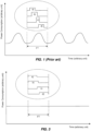
- Fig. 1 An example of the variation of power consumption of the video image processing pipeline is illustrated in Fig. 1 .
- the characteristics of the power consumption of the video image processing pipeline is similar to a sinus wave with the same frequency as the frame rate.
- FT time span of a video frame
- the variation in power consumption of the video image processing pipeline is due to the different power consumption of individual processes of the video image processing pipeline.
- the power consumption of four different individual processes of a video image processing pipeline building up the power consumption illustrated in Fig. 1 is illustrated in the Fig. 1 within the oval insert in the top of the figure as consumption diagrams a)-d).
- Varying power consumption of the video image processing pipeline may have different drawbacks.
- a powering unit powering the video image processing pipeline must be dimensioned according to the peak power consumption. Hence, there is a need for evening out the power consumption of the video image processing pipeline.
- WO 2013/105913 A2 examples are disclosed for adjusting a performance state of a graphics subsystem and/or a processor based on a comparison of an average frame rate to a target frame rate.
- the adjustment of the performance state is made in order to reduce the power consumption in general of the graphics subsystem.
- YUHO JIN ET AL "Peak Power Control for a QoS Capable OnChip Network", PARALLEL PROCESSING, 2005. ICPP 2005. INTERNATIONAL CONFERENCE ON OSLO, NORWAY 14-17 JUNE 2005, PISCATAWAY. NJ. USA.IEEE. 14 June 2005. oaoes 585-592 , discloses a credit-based peak power control scheme for a Network-on-Chip. The disclosed scheme regulates each flow's injection rate at the sender to minimize performance penalty with two different throttling schemes for real-time traffic and best-effort traffic: a rate-based throttling and an energy-budget based throttling, respectively.
- a video image processing pipeline controller is provided according to claim 1.
- the bandwidth available for communication with the system memory is tuned.
- Some or all of the processing functions of the video image processing pipeline communicating with the system memory will be choked. This will result in that the timing of these processing functions will shift or be prolonged.
- the power consumption may be held on a stable level. Hence, the peak power consumption may be lowered.
- the bandwidth is reduced too much, the video processing pipeline will not be able to produce the video stream with the target frame rate.
- the reduction of bandwidth need to be controlled such that the current frame rate does not drop below the target frame rate.
- the controller is configured to reduce the bandwidth as much as possible while maintaining a constant frame rate.
- the controlling algorithm uses two variables, the target frame rate and the current frame rate at which the video processing pipeline is producing the video stream.
- the controlling of the bandwidth in order to reduce the peak power consumption of the video image processing pipeline may run continuously in the background.
- the powering unit powering the video image processing pipeline may be dimensioned to deliver less power.
- the PoE installation may be dimensioned to deliver less power than without the present reduction of peak power.
- the PoE aggregate may be used for powering more cameras.
- the excess power may be used by other processes in a device comprising the video image processing pipeline.
- Increasing the available bandwidth to a bandwidth at which the current frame rate does not drop below the target frame rate may comprise increasing the available bandwidth to a smallest previous bandwidth at which the current frame rate did not drop below the target frame rate.
- the target frame rate may be an original frame rate.
- the original frame rate may be read out from the video source producing the video image data for the video image pipeline.
- the original frame rate may be read out before regulation of the bandwidth.
- the video image processing pipeline controller may further be configured to globally control the bandwidth of a plurality of memory access channels.
- the video image processing pipeline controller may further be configured to individually control the bandwidth in each of a plurality of memory access channels.
- the video image processing pipeline controller may further be configured to individually control the bandwidth in each of a plurality of memory access channels.
- the video image processing pipeline may comprise two or more of the following processing functions: image sensor correction function, noise reduction function, image scaling function, gamma correction function, image enhancement function, color space conversion function, chroma subsampling function, compression function, data storage function and data transmission function.
- a processing function of the video image processing pipeline may be implemented as a computer software portion run on a general purpose processor or on a graphics processing unit, a field-programmable gate array, a fixed-function application-specific integrated circuit, or an analog circuit.
- the image source may be an image sensor.
- the image source may be an image rendering engine.
- the video image processing system may further comprise: an electrical power consuming unit; and an electrical power managing unit configured to monitor electrical power saved by the controlling of the available bandwidth at which the image processing pipeline is allowed to communicate with the system memory, and to distribute at least a fraction of the saved electrical power to the electrical power consuming unit.
- a method of reducing a peak power consumption in a video image processing pipeline is provided according to claim 11.
- Increasing the available bandwidth to a bandwidth at which the current frame rate does not drop below the target frame rate may comprise increasing the bandwidth to a smallest previous available bandwidth at which the current frame rate did not drop below the target frame rate.
- a non-transitory computer readable recording medium having recorded thereon program code which when executed at a device having processing capabilities is configured to perform the method according to the third aspect.
- Fig. 2 illustrates a video image processing system 1.
- the video image processing system 1 comprises a video source 10, a video image processing pipeline 20, a system memory 30, one or more memory access channels 40, and a video image processing pipeline controller 50.
- the video source 10 is configured to provide video image data.
- the video image data may be a series of images.
- the video source 10 may be an image sensor.
- the image sensor is configured to capture the video image data.
- the image sensor may form part of a video camera.
- the video source 10 may be an image rendering engine.
- the image rendering engine is configured to render the video image data.
- the image rendering engine may be configured to render photorealistic or non-photorealistic images from a 2D or 3D model by means of a computer program.
- the video source 10 is configured to transfer the video image data to the video image processing pipeline 20.
- the video image processing pipeline 20 is configured to process the video image data into video frames.
- the video image processing pipeline 20 comprises a plurality of processing functions 25.
- Each processing function 25 is configured to process the video image data.
- Some of the plurality of processing functions 25 may be dependent on each other. Hence, they need to be executed one after another.
- Some of the plurality of processing functions 25 may be independent on each other. Hence, they may be executed in parallel.
- the processes of the plurality of processing functions 25 are typically finalized well before a subsequent image, in the series of images, is transferred to the video image processing pipeline 20.
- the video image processing pipeline 20 comprises two or more of the following processing functions 25: an image sensor correction function, a noise reduction function, an image scaling function, a gamma correction function, an image enhancement function, a color space conversion function, a chroma subsampling function, a compression function, a data storage function, and a data transmission function.
- the image sensor correction function may comprise a Bayer filter.
- the color space conversion function may comprise conversions between different formats, such as RGB, YUV and YCbCr.
- a specific processing function 25 of the video image processing pipeline 20 may be implemented as a computer software portion run on a general purpose processor or on a graphics processing unit, a field-programmable gate array, a fixed-function application-specific integrated circuit, or an analog circuit. Every one of the plurality of processing function 25 may be implemented using the same type of implementation. Different ones of the plurality of processing function 25 may be implemented using different implementations of the processing function 25. A subset of the plurality of processing function 25 may be implemented using the same type of implementation. Accordingly, the processing function 25 of the video image processing pipeline 20 may be implemented as software, dedicated hardware or firmware, or some combination of dedicated hardware, firmware and/or software.
- the system memory 30 is a memory used by the processing function 25 while processing the video image data into video frames.
- the system memory 30 may be a volatile memory, such as a random-access memory, RAM.
- the processing functions 25 of the image processing pipeline 20 are configured to access the system memory 30 via the one or more memory access channels 40.
- the one or more memory access channels may be direct memory access, DMA, channels.
- the processing functions 25 of the image processing pipeline 20 may be configured to access the system memory 30 via a single memory access channel 40.
- the processing functions 25 of the image processing pipeline 20 may be configured to access the system memory 30 via a plurality of memory access channels 40.
- the video image processing pipeline controller 50 is configured to control a bandwidth of the one or more memory access channels 40.
- the video image processing pipeline controller 50 may be configured to control the bandwidth of each memory access channel 40 individually.
- the bandwidth in each memory access channel 40 may be controlled independent from the bandwidths in the other memory access channels 40.
- the actual power consumption may be given by an electrical power managing unit 70.
- the video image processing pipeline controller 50 may be configured to control the bandwidth of the memory access channels 40 globally.
- the bandwidths of the plurality of memory access channels may be controlled together controlling a total bandwidth of the one or more memory access channels 40.
- the video image processing pipeline controller 50 is configured to control the bandwidth at which processing functions 25 of the video image processing pipeline 20 communicates, over the one or more memory access channels 40, with the system memory 30.
- the video image processing pipeline controller 50 is configured to control the bandwidth such that the bandwidth is reduced.
- the controlling of the bandwidth is made based on a current frame rate at which the video image processing pipeline 20 produces the video stream and a target frame rate of the video image processing pipeline 20.
- the target frame rate may be stored in a memory 55 of the video image processing system 1.
- the target frame rate may be an original frame rate of the video stream.
- the original frame rate may be the frame rate at which the video source is producing the series of images.
- the reduction of the bandwidth is controlled such that it is secured that the current frame rate does not drop below the target frame rate.
- the bandwidth may be controlled based on the current frame rate with the original frame rate as target.
- a reduction of a peak power consumption of the video image processing pipeline 20 may be achieved.
- the power consumption can be held on a stable level. Hence, the peak power consumption may be lowered.
- Fig. 3 Within the oval insert in the top of Fig. 3 the power consumption of the four different individual processes of the video image processing pipeline 20 building up the power consumption as illustrated in Fig. 1 are schematically illustrated after a reduction of the bandwidth according to the above scheme.
- the reduction of the bandwidth may result in that an execution of a specific processing function 25 is spread out in time. This may imply that the power consumption for that specific processing function 25 is also spread out in time. This is illustrated in the oval insert in the top of Fig. 3 , wherein the power consumption of the different processes a)-d) related to the different processing functions 25 are spread out in time as compared with a video image processing system run without reducing the bandwidth, the latter is schematically illustrated in Fig. 1 .
- the reduction of the bandwidth may result in that an execution of a specific processing function 25 is shifted in time. This is also illustrated in the oval insert in the top of Fig. 3 , wherein the power consumption of the processes a) and b) are shifted in time as compared with a video image processing system run without reducing the bandwidth, the latter is schematically illustrated in Fig. 1 .
- some of the plurality of processing functions 25 may be dependent on each other.
- processes a) and c) are depended on each other and processes b) and d) are dependent on each other. Hence, they are executed one after another.
- some of the plurality of processing functions 25 may be independent on each other.
- process a) is independent on processes b) and d).
- process a) may be executed in parallel with processes b) and/or d).
- the video image processing pipeline controller 50 may be configured to tune the bandwidth, at which the processing functions 25 of the image processing pipeline 20 communicates, over the one or more memory access channels 40, with the system memory 30, until the peak power is minimized.
- the video image processing pipeline controller 50 may further be configured to decrease the bandwidth, at which the processing functions 25 of the image processing pipeline 20 communicates, over the one or more memory access channels 40, with the system memory 30, in steps.
- the bandwidth may be reduced in steps until the current frame rate drops below the target frame rate.
- the video image processing pipeline controller 50 may be configured to increase the bandwidth to a bandwidth at which the current frame rate does not drop below the target frame rate. This may, for example, be made by increasing the bandwidth to a smallest previous bandwidth at which the current frame rate did not drop below the target frame rate.
- the video image processing system 1 may further comprise an electrical power consuming unit 60 and an electrical power managing unit 70.
- the electrical power consuming unit 60 may be one or more of an illuminator device configured to illuminate a scene viewed by the video source 10, a pan/tilt motor configured to pan/tilt the video source 10, and a cooling arrangement configured to cool one or more components of the system 1.
- the electrical power managing unit 70 is configured to monitor the electrical power saved by the controlling of the bandwidth at which the image processing pipeline 20 communicates, over the one or more memory access channels 40, with the system memory 30.
- the electrical power managing unit 70 may further be configured to distribute at least a fraction of the saved electrical power to the electrical power consuming unit 60.
- the method comprises the following acts. Storing S402 the target frame rate of the video image processing pipeline 20.
- the target frame rate may be stored in the memory 55 of the video image processing system 1.
- Reducing S404 based on a current frame rate at which the video image processing pipeline 20 produces the video stream and the target frame rate, a bandwidth, at which processing functions 25 communicates over the one or more memory access channels 40 with the system memory 30.
- the reducing S404 is performed such that it is secured that the current frame rate does not drop below the target frame rate.
- the act of reducing S404 may be performed by a video image processing pipeline controller 50.
- the act of reducing S404 the bandwidth may comprise decreasing the bandwidth in steps until the current frame rate drops below the target frame rate, and, in response to the current frame rate drops below the target frame rate, increasing the bandwidth to a bandwidth at which the current frame rate does not drop below the target frame rate.
- the act of reducing S404 the bandwidth may further comprise, in response to the current frame rate drops below the target frame rate, increasing the bandwidth to a smallest previous bandwidth at which the current frame rate did not drop below the target frame rate.
- the video image processing system may be implemented in a camera 100. This is illustrated in connection with Fig. 5 .
- the camera 100 may be a monitoring camera.
- the electrical power consuming unit 60 may be one or more of an illuminator device configured to illuminate a scene viewed by the camera 100, a pan/tilt motor configured to pan/tilt the camera 100, and a cooling arrangement configured to cool the camera 100.
Landscapes
- Engineering & Computer Science (AREA)
- Multimedia (AREA)
- Signal Processing (AREA)
- Theoretical Computer Science (AREA)
- Physics & Mathematics (AREA)
- General Physics & Mathematics (AREA)
- Computing Systems (AREA)
- General Engineering & Computer Science (AREA)
- Computer Hardware Design (AREA)
- Studio Devices (AREA)
- Image Processing (AREA)
- Memory System (AREA)
- Television Receiver Circuits (AREA)
Description
- The present invention relates to reduction of peak power consumption in a video image processing pipeline. The present invention also relates to a video image processing pipeline controller and a video image processing system comprising such a controller. The present invention further relates to a method of reducing a peak power consumption in a video image processing pipeline.
- Typically, a video stream is produced by capturing a series of images using an image sensor. Alternatively, the series of images may be rendered by an image rendering engine.
- As an image from the series of images is transferred into a video image processing pipeline a plurality of processes will start working with it in order for producing a video frame. As a rule, the processes are finalized before a subsequent image, in the series of images, is transferred to the video image processing pipeline. The so produced video frames are forming a video stream.
- This will result in a period of idle video image processing pipeline followed by that the video image processing pipeline is running at full capacity. This will result in uneven power consumption. Hence, the power consumption of the video image processing pipeline varies during production of one video frame. An example of the variation of power consumption of the video image processing pipeline is illustrated in
Fig. 1 . As seen, the characteristics of the power consumption of the video image processing pipeline is similar to a sinus wave with the same frequency as the frame rate. InFig. 1 the time span of a video frame is indicated as FT, i.e. frame time. The variation in power consumption of the video image processing pipeline is due to the different power consumption of individual processes of the video image processing pipeline. The power consumption of four different individual processes of a video image processing pipeline building up the power consumption illustrated inFig. 1 is illustrated in theFig. 1 within the oval insert in the top of the figure as consumption diagrams a)-d). - Varying power consumption of the video image processing pipeline may have different drawbacks. For example, a powering unit powering the video image processing pipeline must be dimensioned according to the peak power consumption. Hence, there is a need for evening out the power consumption of the video image processing pipeline.
- In
WO 2013/105913 A2 examples are disclosed for adjusting a performance state of a graphics subsystem and/or a processor based on a comparison of an average frame rate to a target frame rate. The adjustment of the performance state is made in order to reduce the power consumption in general of the graphics subsystem. - BHOJWANI P ET AL: "A Heuristic for Peak Power Constrained Design of Network-on-Chip (NoC) Based Multimode Systems", VLSI DESIGN, 2005. 18TH INTERNATIONAL CONFERENCE ON KOLKATA, INDIA 03-07 JAN. 2005, PISCATAWAY, NJ, USA.IEEE, 3 January 2005, pages 124-129, discloses controlling the peak power of a Network-on-Chip based multimode system by controlling the communication bandwidth between components of the system and the memory. The bandwidth allocation is reduced by scaling down the number of virtual channels that are allocated to the communications.
- YUHO JIN ET AL: "Peak Power Control for a QoS Capable OnChip Network", PARALLEL PROCESSING, 2005. ICPP 2005. INTERNATIONAL CONFERENCE ON OSLO, NORWAY 14-17 JUNE 2005, PISCATAWAY. NJ. USA.IEEE. 14 June 2005. oaoes 585-592, discloses a credit-based peak power control scheme for a Network-on-Chip. The disclosed scheme regulates each flow's injection rate at the sender to minimize performance penalty with two different throttling schemes for real-time traffic and best-effort traffic: a rate-based throttling and an energy-budget based throttling, respectively.
- According to a first aspect a video image processing pipeline controller is provided according to
claim 1. - Accordingly, the bandwidth available for communication with the system memory is tuned. Some or all of the processing functions of the video image processing pipeline communicating with the system memory will be choked. This will result in that the timing of these processing functions will shift or be prolonged. By, in time, shifting and/or prolonging the active time, of some or all of the processing functions of the video image processing pipeline, the power consumption may be held on a stable level. Hence, the peak power consumption may be lowered. If the bandwidth is reduced too much, the video processing pipeline will not be able to produce the video stream with the target frame rate. Hence, the reduction of bandwidth need to be controlled such that the current frame rate does not drop below the target frame rate. In other word, the controller is configured to reduce the bandwidth as much as possible while maintaining a constant frame rate. By controlling the bandwidth of the one or more memory access channels just right, the above can be achieved. The controlling algorithm uses two variables, the target frame rate and the current frame rate at which the video processing pipeline is producing the video stream. The controlling of the bandwidth in order to reduce the peak power consumption of the video image processing pipeline may run continuously in the background.
- By reducing the peak power consumption of the video image processing pipeline the powering unit powering the video image processing pipeline may be dimensioned to deliver less power. For the example of using power over Ethernet, PoE, to power a camera comprising the video image processing pipeline, the PoE installation may be dimensioned to deliver less power than without the present reduction of peak power. Hence, if peak power decreases, the power needed to be delivered by a PoE aggregate may also decrease. Alternatively, the PoE aggregate may be used for powering more cameras.
- Instead of dimensioning down the powering unit, the excess power may be used by other processes in a device comprising the video image processing pipeline.
- Increasing the available bandwidth to a bandwidth at which the current frame rate does not drop below the target frame rate may comprise increasing the available bandwidth to a smallest previous bandwidth at which the current frame rate did not drop below the target frame rate.
- The target frame rate may be an original frame rate. The original frame rate may be read out from the video source producing the video image data for the video image pipeline. The original frame rate may be read out before regulation of the bandwidth.
- The video image processing pipeline controller may further be configured to globally control the bandwidth of a plurality of memory access channels.
- The video image processing pipeline controller may further be configured to individually control the bandwidth in each of a plurality of memory access channels. In order to achieve as good and even control of the power consumption of the video image pipeline as possible, it may be advantageous to control different memory access channels differently. This may possibly be made using an actual measured or estimated power consumption as feedback.
- According to a second aspect a video image processing system is provided. The video image processing system comprises: a video source configured to provide video image data; a video image processing pipeline comprising a plurality of processing functions, wherein each processing function is configured to process the video image data; a system memory, wherein the processing functions of the image processing pipeline are configured to access the system memory via one or more memory access channels; and a video image processing pipeline controller according to the first aspect
The above mentioned features of the video image processing pipeline controller, when applicable, apply to this second aspect as well. In order to avoid undue repetition, reference is made to the above. - The video image processing pipeline may comprise two or more of the following processing functions: image sensor correction function, noise reduction function, image scaling function, gamma correction function, image enhancement function, color space conversion function, chroma subsampling function, compression function, data storage function and data transmission function.
- A processing function of the video image processing pipeline may be implemented as a computer software portion run on a general purpose processor or on a graphics processing unit, a field-programmable gate array, a fixed-function application-specific integrated circuit, or an analog circuit.
- The image source may be an image sensor. The image source may be an image rendering engine.
- The video image processing system may further comprise: an electrical power consuming unit; and an electrical power managing unit configured to monitor electrical power saved by the controlling of the available bandwidth at which the image processing pipeline is allowed to communicate with the system memory, and to distribute at least a fraction of the saved electrical power to the electrical power consuming unit.
- The image processing system may be implemented in a camera. The camera may be a monitoring camera.
- According to a third aspect a method of reducing a peak power consumption in a video image processing pipeline is provided according to claim 11.
- Increasing the available bandwidth to a bandwidth at which the current frame rate does not drop below the target frame rate may comprise increasing the bandwidth to a smallest previous available bandwidth at which the current frame rate did not drop below the target frame rate.
- The above mentioned features of the controller and the system, when applicable, apply to this third aspect as well. In order to avoid undue repetition, reference is made to the above.
- According to a fourth aspect a non-transitory computer readable recording medium having recorded thereon program code which when executed at a device having processing capabilities is configured to perform the method according to the third aspect.
- A further scope of applicability of the present invention will become apparent from the detailed description given below. However, it should be understood that the detailed description and specific examples, while indicating preferred embodiments of the invention, are given by way of illustration only, since various changes and modifications within the scope of the invention will become apparent to those skilled in the art from this detailed description.
- Hence, it is to be understood that this invention is not limited to the particular component parts of the device described or acts of the methods described as such device and method may vary. It is also to be understood that the terminology used herein is for purpose of describing particular embodiments only, and is not intended to be limiting. It must be noted that, as used in the specification and the appended claim, the articles "a," "an," "the," and "said" are intended to mean that there are one or more of the elements unless the context clearly dictates otherwise. Thus, for example, reference to "a unit" or "the unit" may include several devices, and the like. Furthermore, the words "comprising", "including", "containing" and similar wordings does not exclude other elements or steps.
- The above and other aspects of the present invention will now be described in more detail, with reference to appended drawings showing embodiments of the invention. The figures should not be considered limiting the invention to the specific embodiment; instead they are used for explaining and understanding the invention.
- As illustrated in the figures, the sizes of layers and regions may be exaggerated for illustrative purposes and, thus, are provided to illustrate the general structures of embodiments of the present invention. Like reference numerals refer to like elements throughout.
-
Fig. 1 schematically illustrates power consumption of a prior art video image processing pipeline over a plurality of frame times as well as power consumption of four different individual processes of the prior art video image processing pipeline. -
Fig. 2 schematically illustrates a video image processing system. -
Fig. 3 schematically illustrates power consumption of a video image processing pipeline over a plurality of frame times as well as power consumption of four different individual processes of the video image processing pipeline. -
Fig. 4 is a block scheme of a method of reducing a peak power consumption in a video image processing pipeline. -
Fig. 5 schematically illustrates a camera comprising the video image processing system ofFig. 2 . - The present invention will now be described more fully hereinafter with reference to the accompanying drawings, in which currently preferred embodiments of the invention are shown. This invention may, however, be embodied in many different forms and should not be construed as limited to the embodiments set forth herein; rather, these embodiments are provided for thoroughness and completeness, and to fully convey the scope of the invention to the skilled person.
-
Fig. 2 illustrates a videoimage processing system 1. The videoimage processing system 1 comprises avideo source 10, a videoimage processing pipeline 20, asystem memory 30, one or morememory access channels 40, and a video imageprocessing pipeline controller 50. - The
video source 10 is configured to provide video image data. The video image data may be a series of images. Thevideo source 10 may be an image sensor. The image sensor is configured to capture the video image data. The image sensor may form part of a video camera. Alternatively, or in combination, thevideo source 10 may be an image rendering engine. The image rendering engine is configured to render the video image data. The image rendering engine may be configured to render photorealistic or non-photorealistic images from a 2D or 3D model by means of a computer program. Thevideo source 10 is configured to transfer the video image data to the videoimage processing pipeline 20. - The video
image processing pipeline 20 is configured to process the video image data into video frames. The videoimage processing pipeline 20 comprises a plurality of processing functions 25. Eachprocessing function 25 is configured to process the video image data. Some of the plurality of processing functions 25 may be dependent on each other. Hence, they need to be executed one after another. Some of the plurality of processing functions 25 may be independent on each other. Hence, they may be executed in parallel. The processes of the plurality of processing functions 25 are typically finalized well before a subsequent image, in the series of images, is transferred to the videoimage processing pipeline 20. - The video
image processing pipeline 20 comprises two or more of the following processing functions 25: an image sensor correction function, a noise reduction function, an image scaling function, a gamma correction function, an image enhancement function, a color space conversion function, a chroma subsampling function, a compression function, a data storage function, and a data transmission function. The image sensor correction function may comprise a Bayer filter. The color space conversion function may comprise conversions between different formats, such as RGB, YUV and YCbCr. - A
specific processing function 25 of the videoimage processing pipeline 20 may be implemented as a computer software portion run on a general purpose processor or on a graphics processing unit, a field-programmable gate array, a fixed-function application-specific integrated circuit, or an analog circuit. Every one of the plurality ofprocessing function 25 may be implemented using the same type of implementation. Different ones of the plurality ofprocessing function 25 may be implemented using different implementations of theprocessing function 25. A subset of the plurality ofprocessing function 25 may be implemented using the same type of implementation. Accordingly, theprocessing function 25 of the videoimage processing pipeline 20 may be implemented as software, dedicated hardware or firmware, or some combination of dedicated hardware, firmware and/or software. - The
system memory 30 is a memory used by theprocessing function 25 while processing the video image data into video frames. Thesystem memory 30 may be a volatile memory, such as a random-access memory, RAM. - The processing functions 25 of the
image processing pipeline 20 are configured to access thesystem memory 30 via the one or morememory access channels 40. The one or more memory access channels may be direct memory access, DMA, channels. The processing functions 25 of theimage processing pipeline 20 may be configured to access thesystem memory 30 via a singlememory access channel 40. The processing functions 25 of theimage processing pipeline 20 may be configured to access thesystem memory 30 via a plurality ofmemory access channels 40. - The video image
processing pipeline controller 50 is configured to control a bandwidth of the one or morememory access channels 40. In case of a plurality ofmemory access channels 40, the video imageprocessing pipeline controller 50 may be configured to control the bandwidth of eachmemory access channel 40 individually. Hence, the bandwidth in eachmemory access channel 40 may be controlled independent from the bandwidths in the othermemory access channels 40. In order to achieve as good and even control of the power consumption of thevideo image pipeline 20 as possible, it may be advantageous to control different memory access channels differently. This may possibly be made using an actual measured or estimated power consumption as feedback. The actual power consumption may be given by an electricalpower managing unit 70. Alternatively, in case of a plurality ofmemory access channels 40, the video imageprocessing pipeline controller 50 may be configured to control the bandwidth of thememory access channels 40 globally. Hence, the bandwidths of the plurality of memory access channels may be controlled together controlling a total bandwidth of the one or morememory access channels 40. Hence, the video imageprocessing pipeline controller 50 is configured to control the bandwidth at which processing functions 25 of the videoimage processing pipeline 20 communicates, over the one or morememory access channels 40, with thesystem memory 30. The video imageprocessing pipeline controller 50 is configured to control the bandwidth such that the bandwidth is reduced. The controlling of the bandwidth is made based on a current frame rate at which the videoimage processing pipeline 20 produces the video stream and a target frame rate of the videoimage processing pipeline 20. The target frame rate may be stored in amemory 55 of the videoimage processing system 1. The target frame rate may be an original frame rate of the video stream. The original frame rate may be the frame rate at which the video source is producing the series of images. The reduction of the bandwidth is controlled such that it is secured that the current frame rate does not drop below the target frame rate. Hence, the bandwidth may be controlled based on the current frame rate with the original frame rate as target. - By controlling the bandwidth of the one or more
memory access channels 40 in accordance with this scheme a reduction of a peak power consumption of the videoimage processing pipeline 20 may be achieved. This since a reduction in the bandwidth induces a shift in and/or prolongs the active time, within a frame time, of the processing functions 25. By shifting and/or prolonging the active time the power consumption can be held on a stable level. Hence, the peak power consumption may be lowered. This is schematically illustrated in connection withFig. 3 . Within the oval insert in the top ofFig. 3 the power consumption of the four different individual processes of the videoimage processing pipeline 20 building up the power consumption as illustrated inFig. 1 are schematically illustrated after a reduction of the bandwidth according to the above scheme. The reduction of the bandwidth may result in that an execution of aspecific processing function 25 is spread out in time. This may imply that the power consumption for thatspecific processing function 25 is also spread out in time. This is illustrated in the oval insert in the top ofFig. 3 , wherein the power consumption of the different processes a)-d) related to the different processing functions 25 are spread out in time as compared with a video image processing system run without reducing the bandwidth, the latter is schematically illustrated inFig. 1 . Alternatively, or in combination, the reduction of the bandwidth may result in that an execution of aspecific processing function 25 is shifted in time. This is also illustrated in the oval insert in the top ofFig. 3 , wherein the power consumption of the processes a) and b) are shifted in time as compared with a video image processing system run without reducing the bandwidth, the latter is schematically illustrated inFig. 1 . - As mentioned above, some of the plurality of processing functions 25 may be dependent on each other. In the example illustrated in
Figs 1 and 3 processes a) and c) are depended on each other and processes b) and d) are dependent on each other. Hence, they are executed one after another. Further, also as mentioned above, some of the plurality of processing functions 25 may be independent on each other. For example, in the example illustrated inFigs 1 and 3 process a) is independent on processes b) and d). Hence, process a) may be executed in parallel with processes b) and/or d). - The video image
processing pipeline controller 50 may be configured to tune the bandwidth, at which the processing functions 25 of theimage processing pipeline 20 communicates, over the one or morememory access channels 40, with thesystem memory 30, until the peak power is minimized. - The video image
processing pipeline controller 50 may further be configured to decrease the bandwidth, at which the processing functions 25 of theimage processing pipeline 20 communicates, over the one or morememory access channels 40, with thesystem memory 30, in steps. The bandwidth may be reduced in steps until the current frame rate drops below the target frame rate. In response to the current frame rate drops below the target frame rate, the video imageprocessing pipeline controller 50 may be configured to increase the bandwidth to a bandwidth at which the current frame rate does not drop below the target frame rate. This may, for example, be made by increasing the bandwidth to a smallest previous bandwidth at which the current frame rate did not drop below the target frame rate. - The video
image processing system 1 may further comprise an electricalpower consuming unit 60 and an electricalpower managing unit 70. - The electrical
power consuming unit 60 may be one or more of an illuminator device configured to illuminate a scene viewed by thevideo source 10, a pan/tilt motor configured to pan/tilt thevideo source 10, and a cooling arrangement configured to cool one or more components of thesystem 1. - The electrical
power managing unit 70 is configured to monitor the electrical power saved by the controlling of the bandwidth at which theimage processing pipeline 20 communicates, over the one or morememory access channels 40, with thesystem memory 30. The electricalpower managing unit 70 may further be configured to distribute at least a fraction of the saved electrical power to the electricalpower consuming unit 60. - In connection with
Fig. 4 a method of reducing a peak power consumption in the videoimage processing pipeline 20 will be discussed. The method comprises the following acts. Storing S402 the target frame rate of the videoimage processing pipeline 20. The target frame rate may be stored in thememory 55 of the videoimage processing system 1. Reducing S404, based on a current frame rate at which the videoimage processing pipeline 20 produces the video stream and the target frame rate, a bandwidth, at which processing functions 25 communicates over the one or morememory access channels 40 with thesystem memory 30. The reducing S404 is performed such that it is secured that the current frame rate does not drop below the target frame rate. The act of reducing S404 may be performed by a video imageprocessing pipeline controller 50. The act of reducing S404 the bandwidth may comprise decreasing the bandwidth in steps until the current frame rate drops below the target frame rate, and, in response to the current frame rate drops below the target frame rate, increasing the bandwidth to a bandwidth at which the current frame rate does not drop below the target frame rate. The act of reducing S404 the bandwidth may further comprise, in response to the current frame rate drops below the target frame rate, increasing the bandwidth to a smallest previous bandwidth at which the current frame rate did not drop below the target frame rate. - The person skilled in the art realizes that the present invention by no means is limited to the preferred embodiments described above. On the contrary, many modifications and variations are possible within the scope of the appended claims.
- For example, the video image processing system may be implemented in a
camera 100. This is illustrated in connection withFig. 5 . Thecamera 100 may be a monitoring camera. In case the system is implemented in thecamera 100, the electricalpower consuming unit 60 may be one or more of an illuminator device configured to illuminate a scene viewed by thecamera 100, a pan/tilt motor configured to pan/tilt thecamera 100, and a cooling arrangement configured to cool thecamera 100. - Additionally, variations to the disclosed embodiments can be understood and effected by the skilled person in practicing the claimed invention, from a study of the drawings, the disclosure, and the appended claims.
Claims (13)
- A video image processing pipeline controller configured to control an available bandwidth at which processing functions (25) of a video image processing pipeline (20) is allowed to communicate, over one or more memory access channels (40), with a system memory (30),wherein the video image processing pipeline controller is configured to reduce the available bandwidth while securing that the current frame rate does not drop below a target frame rate, at which the video image processing pipeline (20) produces a video stream, thereby inducing a shift in an active time and/or prolonging the active time, within a frame time, of the processing functions (25) such that a peak power consumption of the video image processing pipeline (20) is reduced,wherein the video image processing pipeline controller is configured to reduce the available bandwidth while securing that the current frame rate does not drop below a target frame rate by decreasing the available bandwidth in steps until a current frame rate drops below the target frame rate, and, in response to the current frame rate drops below the target frame rate, increasing the available bandwidth to a bandwidth at which the current frame rate does not drop below the target frame rate.
- The video image processing pipeline controller according to claim 1, wherein increasing the available bandwidth to a bandwidth at which the current frame rate does not drop below the target frame rate comprises increasing the available bandwidth to a smallest previous bandwidth at which the current frame rate did not drop below the target frame rate.
- The video image processing pipeline controller according to claim 1 or 2, wherein the target frame rate is an original frame rate.
- The video image processing pipeline controller according to any one of claims 1-3, further configured to globally control the bandwidth of a plurality of memory access channels (40).
- The video image processing pipeline controller according to any one of claims 1-3, further configured to individually control the bandwidth in each of a plurality of memory access channels.
- A video image processing system comprising:a video source (10) configured to provide video image data;a video image processing pipeline (20) comprising a plurality of processing functions (25), wherein each processing function is configured to process the video image data;a system memory (30), wherein the processing functions (25) of the image processing pipeline (20) are configured to access the system memory (30) via one or more memory access channels (40); anda video image processing pipeline controller (50) according to any one of claims 1-5.
- The video image processing system according to claim 6, wherein a processing function (25) of the video image processing pipeline (20) is implemented as a computer software portion run on a general purpose processor or on a graphics processing unit, a field-programmable gate array, a fixed-function application-specific integrated circuit, or an analog circuit.
- The video image processing system according to claim 6 or 7, wherein the image source (10) is an image sensor or an image rendering engine.
- The video image processing system according to any one of claims 6-8, wherein the video image processing system further comprises:an electrical power consuming unit (60); andan electrical power managing unit (70) configured to monitor electrical power saved by the controlling of the available bandwidth at which the image processing pipeline (20) is allowed to communicate with the system memory (30), and to distribute at least a fraction of the saved electrical power to the electrical power consuming unit (60).
- The video image processing system according to any one of claims 6-9, wherein the image processing system is implemented in a camera (100), such as a monitoring camera.
- A method of reducing a peak power consumption in a video image processing pipeline (20) configured to process video image data into a video stream, the video image processing pipeline (20) comprising a plurality of processing functions (25), wherein each processing function (25) is configured to process video image data, and while processing of video image data, the processing functions (25) are configured to access a system memory (30) over one or more memory access channels (40), the method comprising:reducing, by a video image processing pipeline controller (50), an available bandwidth, at which processing functions (25) are allowed to communicate over the one or more memory access channels with the system memory (30), while securing that the current frame rate does not drop below a target frame rate, at which the video image processing pipeline (20) produces the video stream, thereby inducing a shift in an active time and/or prolonging the active time, within a frame time, of the processing functions (25) such that a peak power consumption of the video image processing pipeline (20) is reduced,wherein the act of reducing the available bandwidth, at which processing functions (25) are allowed to communicate over the one or more memory access channels with the system memory (30), while securing that the current frame rate does not drop below a target frame rate comprises decreasing the available bandwidth in steps until a current frame rate drops below the target frame rate, and, in response to the current frame rate drops below the target frame rate, increasing the available bandwidth to a bandwidth at which the current frame rate does not drop below the target frame rate.
- The method according to claim 11, wherein increasing the available bandwidth to a bandwidth at which the current frame rate does not drop below the target frame rate comprises increasing the available bandwidth to a smallest previous bandwidth at which the current frame rate did not drop below the target frame rate.
- A non-transitory computer readable recording medium having recorded thereon program code which when executed at a device having processing capabilities is configured to perform the method according to claim 11 or 12.
Priority Applications (6)
| Application Number | Priority Date | Filing Date | Title |
|---|---|---|---|
| EP18188672.2A EP3611722B1 (en) | 2018-08-13 | 2018-08-13 | Controller and method for reducing a peak power consumption of a video image processing pipeline |
| KR1020190090836A KR102391869B1 (en) | 2018-08-13 | 2019-07-26 | Controller and method for producing a peak power consumption of a video image processing pipeline |
| JP2019139344A JP7190403B2 (en) | 2018-08-13 | 2019-07-30 | Controller and method for reducing peak power consumption in video image processing pipeline |
| CN201910729139.2A CN110876017B (en) | 2018-08-13 | 2019-08-08 | Controller and method for reducing peak power consumption of video image processing pipeline |
| US16/537,926 US11200635B2 (en) | 2018-08-13 | 2019-08-12 | Controller and method for reducing a peak power consumption of a video image processing pipeline |
| TW108128761A TWI771607B (en) | 2018-08-13 | 2019-08-13 | Controller and method for reducing a peak power consumption of a video image processing pipeline |
Applications Claiming Priority (1)
| Application Number | Priority Date | Filing Date | Title |
|---|---|---|---|
| EP18188672.2A EP3611722B1 (en) | 2018-08-13 | 2018-08-13 | Controller and method for reducing a peak power consumption of a video image processing pipeline |
Publications (3)
| Publication Number | Publication Date |
|---|---|
| EP3611722A1 EP3611722A1 (en) | 2020-02-19 |
| EP3611722B1 true EP3611722B1 (en) | 2024-09-25 |
| EP3611722C0 EP3611722C0 (en) | 2024-09-25 |
Family
ID=63442385
Family Applications (1)
| Application Number | Title | Priority Date | Filing Date |
|---|---|---|---|
| EP18188672.2A Active EP3611722B1 (en) | 2018-08-13 | 2018-08-13 | Controller and method for reducing a peak power consumption of a video image processing pipeline |
Country Status (6)
| Country | Link |
|---|---|
| US (1) | US11200635B2 (en) |
| EP (1) | EP3611722B1 (en) |
| JP (1) | JP7190403B2 (en) |
| KR (1) | KR102391869B1 (en) |
| CN (1) | CN110876017B (en) |
| TW (1) | TWI771607B (en) |
Families Citing this family (3)
| Publication number | Priority date | Publication date | Assignee | Title |
|---|---|---|---|---|
| JP7491006B2 (en) * | 2020-03-23 | 2024-05-28 | 富士フイルムビジネスイノベーション株式会社 | Information processing device and program |
| CN115562469B (en) * | 2022-12-07 | 2023-03-07 | 深流微智能科技(深圳)有限公司 | Power consumption management method and device, image processor and storage medium |
| US12212888B2 (en) | 2023-06-20 | 2025-01-28 | Microsoft Technology Licensing, Llc | Computer system for preprocessing video stream at requested video data rate parameter |
Family Cites Families (32)
| Publication number | Priority date | Publication date | Assignee | Title |
|---|---|---|---|---|
| US6115420A (en) * | 1997-03-14 | 2000-09-05 | Microsoft Corporation | Digital video signal encoder and encoding method |
| US20010043177A1 (en) | 2000-04-14 | 2001-11-22 | Huston James R. | System and method for color and grayscale drive methods for graphical displays utilizing analog controlled waveforms |
| JP3825615B2 (en) * | 2000-08-11 | 2006-09-27 | 株式会社東芝 | Moving picture coding apparatus, moving picture coding method, and medium recording program |
| US6950105B2 (en) * | 2002-06-03 | 2005-09-27 | Ati Technologies Inc. | Power consumption management in a video graphics accelerator |
| JP4228271B2 (en) * | 2002-07-09 | 2009-02-25 | 日本電気株式会社 | Video data compression apparatus and video data compression method |
| JP4676888B2 (en) | 2005-01-25 | 2011-04-27 | パナソニック株式会社 | Data processing device |
| TWI326428B (en) * | 2005-03-18 | 2010-06-21 | Marvell World Trade Ltd | Real-time control apparatus having a multi-thread processor |
| JP2008026761A (en) * | 2006-07-25 | 2008-02-07 | Sony Corp | Power consumption control device, image processing device, self-luminous display device, electronic device, power consumption control method, and computer program |
| US8099583B2 (en) | 2006-08-23 | 2012-01-17 | Axis Semiconductor, Inc. | Method of and apparatus and architecture for real time signal processing by switch-controlled programmable processor configuring and flexible pipeline and parallel processing |
| US20080055318A1 (en) * | 2006-08-31 | 2008-03-06 | Glen David I J | Dynamic frame rate adjustment |
| US7903871B2 (en) * | 2007-04-05 | 2011-03-08 | Arecont Vision, Llc. | System and method for image processing of multi-sensor network cameras |
| US8381215B2 (en) * | 2007-09-27 | 2013-02-19 | Oracle America, Inc. | Method and system for power-management aware dispatcher |
| US8775839B2 (en) | 2008-02-08 | 2014-07-08 | Texas Instruments Incorporated | Global hardware supervised power transition management circuits, processes and systems |
| US8181003B2 (en) | 2008-05-29 | 2012-05-15 | Axis Semiconductor, Inc. | Instruction set design, control and communication in programmable microprocessor cores and the like |
| US8831090B2 (en) * | 2008-11-18 | 2014-09-09 | Avigilon Corporation | Method, system and apparatus for image capture, analysis and transmission |
| WO2010144566A1 (en) * | 2009-06-09 | 2010-12-16 | Wayne State University | Automated video surveillance systems |
| US8964498B2 (en) * | 2011-11-15 | 2015-02-24 | Marvell World Trade Ltd. | Systems and methods for reducing peak power consumption in a solid state drive controller |
| US20140204101A1 (en) * | 2011-11-30 | 2014-07-24 | Murali Ramadoss | Adaptive frame rate control for a graphics subsystem |
| KR20140099295A (en) | 2011-12-28 | 2014-08-11 | 인텔 코포레이션 | Pipelined image processing sequencer |
| US9430242B2 (en) | 2012-04-02 | 2016-08-30 | Nvidia Corporation | Throttling instruction issue rate based on updated moving average to avoid surges in DI/DT |
| US9800781B2 (en) * | 2013-03-15 | 2017-10-24 | Intel Corporation | Method, apparatus, system, and computer readable medium for image processing software module configuration |
| JP6225446B2 (en) * | 2013-03-26 | 2017-11-08 | 富士通株式会社 | Moving image data distribution apparatus, method, program, and system |
| KR102145420B1 (en) | 2013-07-25 | 2020-08-18 | 삼성전자주식회사 | Storage system changing data transfer speed manager and method for changing data transfer speed thereof |
| US9606916B2 (en) * | 2013-09-13 | 2017-03-28 | Samsung Electronics Co., Ltd. | Semiconductor devices including application processor connected to high-bandwidth memory and low-bandwidth memory, and channel interleaving method thereof |
| US9405345B2 (en) | 2013-09-27 | 2016-08-02 | Intel Corporation | Constraining processor operation based on power envelope information |
| US20160227235A1 (en) * | 2015-02-02 | 2016-08-04 | Yaniv Frishman | Wireless bandwidth reduction in an encoder |
| KR102432804B1 (en) * | 2015-06-02 | 2022-08-16 | 한화테크윈 주식회사 | Video capture device using MJPEG |
| US9955191B2 (en) * | 2015-07-01 | 2018-04-24 | At&T Intellectual Property I, L.P. | Method and apparatus for managing bandwidth in providing communication services |
| US20170244894A1 (en) * | 2016-02-22 | 2017-08-24 | Seastar Labs, Inc. | Method and Apparatus for Managing Latency of Remote Video Production |
| KR102519727B1 (en) * | 2016-08-02 | 2023-04-10 | 삼성전자주식회사 | A display driving method and a display driving circuit and an electronic device supporting the same |
| US20180137668A1 (en) * | 2016-11-12 | 2018-05-17 | Intel Corporation | Dynamically selecting optimum graphics frequency and graphics power gating configuration |
| JP6947010B2 (en) * | 2017-12-22 | 2021-10-13 | 富士通株式会社 | Video coding device, video coding method, and computer program for video coding |
-
2018
- 2018-08-13 EP EP18188672.2A patent/EP3611722B1/en active Active
-
2019
- 2019-07-26 KR KR1020190090836A patent/KR102391869B1/en active Active
- 2019-07-30 JP JP2019139344A patent/JP7190403B2/en active Active
- 2019-08-08 CN CN201910729139.2A patent/CN110876017B/en active Active
- 2019-08-12 US US16/537,926 patent/US11200635B2/en active Active
- 2019-08-13 TW TW108128761A patent/TWI771607B/en active
Non-Patent Citations (2)
| Title |
|---|
| BHOJWANI P ET AL: "A Heuristic for Peak Power Constrained Design of Network-on-Chip (NoC) Based Multimode Systems", VLSI DESIGN, 2005. 18TH INTERNATIONAL CONFERENCE ON KOLKATA, INDIA 03-07 JAN. 2005, PISCATAWAY, NJ, USA,IEEE, 3 January 2005 (2005-01-03), pages 124 - 129, XP010769843, ISBN: 978-0-7695-2264-7, DOI: 10.1109/ICVD.2005.12 * |
| YUHO JIN ET AL: "Peak Power Control for a QoS Capable On-Chip Network", PARALLEL PROCESSING, 2005. ICPP 2005. INTERNATIONAL CONFERENCE ON OSLO, NORWAY 14-17 JUNE 2005, PISCATAWAY, NJ, USA,IEEE, 14 June 2005 (2005-06-14), pages 585 - 592, XP010820928, ISBN: 978-0-7695-2380-4 * |
Also Published As
| Publication number | Publication date |
|---|---|
| TWI771607B (en) | 2022-07-21 |
| EP3611722A1 (en) | 2020-02-19 |
| KR20200019084A (en) | 2020-02-21 |
| KR102391869B1 (en) | 2022-04-27 |
| EP3611722C0 (en) | 2024-09-25 |
| TW202020801A (en) | 2020-06-01 |
| US20200051204A1 (en) | 2020-02-13 |
| JP2020061728A (en) | 2020-04-16 |
| CN110876017B (en) | 2022-12-23 |
| CN110876017A (en) | 2020-03-10 |
| US11200635B2 (en) | 2021-12-14 |
| JP7190403B2 (en) | 2022-12-15 |
Similar Documents
| Publication | Publication Date | Title |
|---|---|---|
| US6882361B1 (en) | Imager linked with image processing station | |
| EP3611722B1 (en) | Controller and method for reducing a peak power consumption of a video image processing pipeline | |
| WO2021244341A1 (en) | Picture coding method and apparatus, electronic device and computer readable storage medium | |
| US9813469B2 (en) | Method and devices for negotiating bandwidth in a peer-to-peer network | |
| US10341686B2 (en) | Method for dynamically adapting the encoding of an audio and/or video stream transmitted to a device | |
| JP2020518174A (en) | Video frame coding method, terminal, and storage medium | |
| US20240357138A1 (en) | Human visual system adaptive video coding | |
| KR102500352B1 (en) | System and method for processing super-resolution images based on deep learning and computer program for the same | |
| US20160360148A1 (en) | Imaging apparatus using mjpeg compression method | |
| US20130101043A1 (en) | Encoding apparatus, encoding method and program | |
| CN120017832B (en) | A block optimization method, device and medium based on ultra-high-definition video transmission | |
| CN115984083B (en) | Electronic device and image processing method of electronic device | |
| CN117956167A (en) | Code rate control method and device for video coding and computer readable storage medium | |
| CN118714328A (en) | Adaptive encoding method, device and medium based on GOP scene switching detection | |
| CN114630120A (en) | Video compression method and circuit system based on self-adaptive compression rate | |
| CN118429202A (en) | Video image enhancement method, device and electronic equipment based on neural network | |
| CN114039931B (en) | Method, device, equipment and medium for controlling data transmission | |
| CN112788364B (en) | Code stream dynamic adjustment device, method and computer-readable storage medium | |
| Chen et al. | Improving video coding at scene cuts using attention based adaptive bit allocation | |
| CN116546244B (en) | Methods for video processing and transmission in drone swarm detection, drones and storage media | |
| JPH11196422A (en) | Encode method of image signal | |
| CN119788804A (en) | Video bit rate control method, electronic device and program product | |
| KR102500837B1 (en) | Apparatus and method for image processing | |
| CN116506740A (en) | Image processing method and device for multi-image signal processor of mobile and mooring integrated camera | |
| CN119946261A (en) | Video adaptive encoding method, device, equipment and medium based on dynamic information |
Legal Events
| Date | Code | Title | Description |
|---|---|---|---|
| PUAI | Public reference made under article 153(3) epc to a published international application that has entered the european phase |
Free format text: ORIGINAL CODE: 0009012 |
|
| STAA | Information on the status of an ep patent application or granted ep patent |
Free format text: STATUS: REQUEST FOR EXAMINATION WAS MADE |
|
| 17P | Request for examination filed |
Effective date: 20190308 |
|
| AK | Designated contracting states |
Kind code of ref document: A1 Designated state(s): AL AT BE BG CH CY CZ DE DK EE ES FI FR GB GR HR HU IE IS IT LI LT LU LV MC MK MT NL NO PL PT RO RS SE SI SK SM TR |
|
| AX | Request for extension of the european patent |
Extension state: BA ME |
|
| RAP1 | Party data changed (applicant data changed or rights of an application transferred) |
Owner name: AXIS AB |
|
| STAA | Information on the status of an ep patent application or granted ep patent |
Free format text: STATUS: EXAMINATION IS IN PROGRESS |
|
| 17Q | First examination report despatched |
Effective date: 20210428 |
|
| GRAP | Despatch of communication of intention to grant a patent |
Free format text: ORIGINAL CODE: EPIDOSNIGR1 |
|
| STAA | Information on the status of an ep patent application or granted ep patent |
Free format text: STATUS: GRANT OF PATENT IS INTENDED |
|
| INTG | Intention to grant announced |
Effective date: 20240415 |
|
| GRAS | Grant fee paid |
Free format text: ORIGINAL CODE: EPIDOSNIGR3 |
|
| GRAA | (expected) grant |
Free format text: ORIGINAL CODE: 0009210 |
|
| STAA | Information on the status of an ep patent application or granted ep patent |
Free format text: STATUS: THE PATENT HAS BEEN GRANTED |
|
| AK | Designated contracting states |
Kind code of ref document: B1 Designated state(s): AL AT BE BG CH CY CZ DE DK EE ES FI FR GB GR HR HU IE IS IT LI LT LU LV MC MK MT NL NO PL PT RO RS SE SI SK SM TR |
|
| REG | Reference to a national code |
Ref country code: GB Ref legal event code: FG4D |
|
| REG | Reference to a national code |
Ref country code: CH Ref legal event code: EP |
|
| REG | Reference to a national code |
Ref country code: DE Ref legal event code: R096 Ref document number: 602018074663 Country of ref document: DE |
|
| REG | Reference to a national code |
Ref country code: IE Ref legal event code: FG4D |
|
| U01 | Request for unitary effect filed |
Effective date: 20241024 |
|
| U07 | Unitary effect registered |
Designated state(s): AT BE BG DE DK EE FI FR IT LT LU LV MT NL PT RO SE SI Effective date: 20241105 |
|
| PG25 | Lapsed in a contracting state [announced via postgrant information from national office to epo] |
Ref country code: NO Free format text: LAPSE BECAUSE OF FAILURE TO SUBMIT A TRANSLATION OF THE DESCRIPTION OR TO PAY THE FEE WITHIN THE PRESCRIBED TIME-LIMIT Effective date: 20241225 |
|
| PG25 | Lapsed in a contracting state [announced via postgrant information from national office to epo] |
Ref country code: GR Free format text: LAPSE BECAUSE OF FAILURE TO SUBMIT A TRANSLATION OF THE DESCRIPTION OR TO PAY THE FEE WITHIN THE PRESCRIBED TIME-LIMIT Effective date: 20241226 |
|
| PG25 | Lapsed in a contracting state [announced via postgrant information from national office to epo] |
Ref country code: RS Free format text: LAPSE BECAUSE OF FAILURE TO SUBMIT A TRANSLATION OF THE DESCRIPTION OR TO PAY THE FEE WITHIN THE PRESCRIBED TIME-LIMIT Effective date: 20241225 |
|
| PG25 | Lapsed in a contracting state [announced via postgrant information from national office to epo] |
Ref country code: RS Free format text: LAPSE BECAUSE OF FAILURE TO SUBMIT A TRANSLATION OF THE DESCRIPTION OR TO PAY THE FEE WITHIN THE PRESCRIBED TIME-LIMIT Effective date: 20241225 Ref country code: NO Free format text: LAPSE BECAUSE OF FAILURE TO SUBMIT A TRANSLATION OF THE DESCRIPTION OR TO PAY THE FEE WITHIN THE PRESCRIBED TIME-LIMIT Effective date: 20241225 Ref country code: GR Free format text: LAPSE BECAUSE OF FAILURE TO SUBMIT A TRANSLATION OF THE DESCRIPTION OR TO PAY THE FEE WITHIN THE PRESCRIBED TIME-LIMIT Effective date: 20241226 |
|
| PG25 | Lapsed in a contracting state [announced via postgrant information from national office to epo] |
Ref country code: IS Free format text: LAPSE BECAUSE OF FAILURE TO SUBMIT A TRANSLATION OF THE DESCRIPTION OR TO PAY THE FEE WITHIN THE PRESCRIBED TIME-LIMIT Effective date: 20250125 |
|
| PG25 | Lapsed in a contracting state [announced via postgrant information from national office to epo] |
Ref country code: SM Free format text: LAPSE BECAUSE OF FAILURE TO SUBMIT A TRANSLATION OF THE DESCRIPTION OR TO PAY THE FEE WITHIN THE PRESCRIBED TIME-LIMIT Effective date: 20240925 |
|
| PG25 | Lapsed in a contracting state [announced via postgrant information from national office to epo] |
Ref country code: ES Free format text: LAPSE BECAUSE OF FAILURE TO SUBMIT A TRANSLATION OF THE DESCRIPTION OR TO PAY THE FEE WITHIN THE PRESCRIBED TIME-LIMIT Effective date: 20240925 |
|
| PG25 | Lapsed in a contracting state [announced via postgrant information from national office to epo] |
Ref country code: PL Free format text: LAPSE BECAUSE OF FAILURE TO SUBMIT A TRANSLATION OF THE DESCRIPTION OR TO PAY THE FEE WITHIN THE PRESCRIBED TIME-LIMIT Effective date: 20240925 Ref country code: CZ Free format text: LAPSE BECAUSE OF FAILURE TO SUBMIT A TRANSLATION OF THE DESCRIPTION OR TO PAY THE FEE WITHIN THE PRESCRIBED TIME-LIMIT Effective date: 20240925 |
|
| PG25 | Lapsed in a contracting state [announced via postgrant information from national office to epo] |
Ref country code: SK Free format text: LAPSE BECAUSE OF FAILURE TO SUBMIT A TRANSLATION OF THE DESCRIPTION OR TO PAY THE FEE WITHIN THE PRESCRIBED TIME-LIMIT Effective date: 20240925 |
|
| PLBE | No opposition filed within time limit |
Free format text: ORIGINAL CODE: 0009261 |
|
| STAA | Information on the status of an ep patent application or granted ep patent |
Free format text: STATUS: NO OPPOSITION FILED WITHIN TIME LIMIT |
|
| U20 | Renewal fee for the european patent with unitary effect paid |
Year of fee payment: 8 Effective date: 20250723 |
|
| 26N | No opposition filed |
Effective date: 20250626 |
|
| PGFP | Annual fee paid to national office [announced via postgrant information from national office to epo] |
Ref country code: GB Payment date: 20250724 Year of fee payment: 8 |
|
| PG25 | Lapsed in a contracting state [announced via postgrant information from national office to epo] |
Ref country code: HR Free format text: LAPSE BECAUSE OF FAILURE TO SUBMIT A TRANSLATION OF THE DESCRIPTION OR TO PAY THE FEE WITHIN THE PRESCRIBED TIME-LIMIT Effective date: 20240925 |