EP3586922B1 - Neutron capture therapy system - Google Patents
Neutron capture therapy system Download PDFInfo
- Publication number
- EP3586922B1 EP3586922B1 EP19187968.3A EP19187968A EP3586922B1 EP 3586922 B1 EP3586922 B1 EP 3586922B1 EP 19187968 A EP19187968 A EP 19187968A EP 3586922 B1 EP3586922 B1 EP 3586922B1
- Authority
- EP
- European Patent Office
- Prior art keywords
- movable member
- neutron
- neutron generator
- junction surface
- reflector
- Prior art date
- Legal status (The legal status is an assumption and is not a legal conclusion. Google has not performed a legal analysis and makes no representation as to the accuracy of the status listed.)
- Active
Links
- 238000002560 therapeutic procedure Methods 0.000 title claims description 38
- 238000007493 shaping process Methods 0.000 claims description 34
- 238000006243 chemical reaction Methods 0.000 claims description 9
- 230000005855 radiation Effects 0.000 description 7
- 238000000034 method Methods 0.000 description 6
- 230000008569 process Effects 0.000 description 6
- 239000002245 particle Substances 0.000 description 5
- 238000001959 radiotherapy Methods 0.000 description 4
- 210000004881 tumor cell Anatomy 0.000 description 4
- ZOXJGFHDIHLPTG-UHFFFAOYSA-N Boron Chemical compound [B] ZOXJGFHDIHLPTG-UHFFFAOYSA-N 0.000 description 3
- 229910052796 boron Inorganic materials 0.000 description 3
- 230000033001 locomotion Effects 0.000 description 3
- 230000002105 relative biological effectiveness Effects 0.000 description 3
- WHXSMMKQMYFTQS-UHFFFAOYSA-N Lithium Chemical compound [Li] WHXSMMKQMYFTQS-UHFFFAOYSA-N 0.000 description 2
- 206010028980 Neoplasm Diseases 0.000 description 2
- 201000011510 cancer Diseases 0.000 description 2
- 230000007547 defect Effects 0.000 description 2
- 229910052744 lithium Inorganic materials 0.000 description 2
- 229910052751 metal Inorganic materials 0.000 description 2
- 239000002184 metal Substances 0.000 description 2
- 238000011275 oncology therapy Methods 0.000 description 2
- 230000002285 radioactive effect Effects 0.000 description 2
- 238000002626 targeted therapy Methods 0.000 description 2
- GUTLYIVDDKVIGB-OUBTZVSYSA-N Cobalt-60 Chemical compound [60Co] GUTLYIVDDKVIGB-OUBTZVSYSA-N 0.000 description 1
- 201000010915 Glioblastoma multiforme Diseases 0.000 description 1
- 230000001133 acceleration Effects 0.000 description 1
- 230000009471 action Effects 0.000 description 1
- 230000004913 activation Effects 0.000 description 1
- 230000000712 assembly Effects 0.000 description 1
- 238000000429 assembly Methods 0.000 description 1
- 229910052790 beryllium Inorganic materials 0.000 description 1
- ATBAMAFKBVZNFJ-UHFFFAOYSA-N beryllium atom Chemical compound [Be] ATBAMAFKBVZNFJ-UHFFFAOYSA-N 0.000 description 1
- 238000002512 chemotherapy Methods 0.000 description 1
- 239000003814 drug Substances 0.000 description 1
- 238000010894 electron beam technology Methods 0.000 description 1
- 238000009201 electron therapy Methods 0.000 description 1
- 230000004907 flux Effects 0.000 description 1
- 208000005017 glioblastoma Diseases 0.000 description 1
- 201000001441 melanoma Diseases 0.000 description 1
- 230000035945 sensitivity Effects 0.000 description 1
- 238000011282 treatment Methods 0.000 description 1
Images


Classifications
-
- A—HUMAN NECESSITIES
- A61—MEDICAL OR VETERINARY SCIENCE; HYGIENE
- A61N—ELECTROTHERAPY; MAGNETOTHERAPY; RADIATION THERAPY; ULTRASOUND THERAPY
- A61N5/00—Radiation therapy
- A61N5/10—X-ray therapy; Gamma-ray therapy; Particle-irradiation therapy
- A61N5/1077—Beam delivery systems
-
- A—HUMAN NECESSITIES
- A61—MEDICAL OR VETERINARY SCIENCE; HYGIENE
- A61N—ELECTROTHERAPY; MAGNETOTHERAPY; RADIATION THERAPY; ULTRASOUND THERAPY
- A61N5/00—Radiation therapy
- A61N5/10—X-ray therapy; Gamma-ray therapy; Particle-irradiation therapy
-
- G—PHYSICS
- G21—NUCLEAR PHYSICS; NUCLEAR ENGINEERING
- G21K—TECHNIQUES FOR HANDLING PARTICLES OR IONISING RADIATION NOT OTHERWISE PROVIDED FOR; IRRADIATION DEVICES; GAMMA RAY OR X-RAY MICROSCOPES
- G21K5/00—Irradiation devices
- G21K5/04—Irradiation devices with beam-forming means
-
- H—ELECTRICITY
- H05—ELECTRIC TECHNIQUES NOT OTHERWISE PROVIDED FOR
- H05H—PLASMA TECHNIQUE; PRODUCTION OF ACCELERATED ELECTRICALLY-CHARGED PARTICLES OR OF NEUTRONS; PRODUCTION OR ACCELERATION OF NEUTRAL MOLECULAR OR ATOMIC BEAMS
- H05H3/00—Production or acceleration of neutral particle beams, e.g. molecular or atomic beams
- H05H3/06—Generating neutron beams
-
- A—HUMAN NECESSITIES
- A61—MEDICAL OR VETERINARY SCIENCE; HYGIENE
- A61N—ELECTROTHERAPY; MAGNETOTHERAPY; RADIATION THERAPY; ULTRASOUND THERAPY
- A61N5/00—Radiation therapy
- A61N5/10—X-ray therapy; Gamma-ray therapy; Particle-irradiation therapy
- A61N2005/1085—X-ray therapy; Gamma-ray therapy; Particle-irradiation therapy characterised by the type of particles applied to the patient
- A61N2005/109—Neutrons
-
- A—HUMAN NECESSITIES
- A61—MEDICAL OR VETERINARY SCIENCE; HYGIENE
- A61N—ELECTROTHERAPY; MAGNETOTHERAPY; RADIATION THERAPY; ULTRASOUND THERAPY
- A61N5/00—Radiation therapy
- A61N5/10—X-ray therapy; Gamma-ray therapy; Particle-irradiation therapy
- A61N2005/1092—Details
- A61N2005/1095—Elements inserted into the radiation path within the system, e.g. filters or wedges
Definitions
- the present disclosure relates generally to a neutron capture therapy system, and, more particularly, to a neutron capture therapy system with a replaceable neutron generator.
- a neutron capture therapy system comprising a beam shaping assembly, wherein the beam shaping assembly comprises: a beam inlet; a neutron generator arranged into the beam shaping assembly, wherein the neutron generator has nuclear reaction with an incident proton beam from the beam inlet to produce neutrons; a moderator adjacent to the neutron generator, wherein the neutrons are moderated by the moderator to epithermal neutron energies; a reflector surrounding the neutron generator and the moderator, wherein the reflector leads the deflected neutrons back to enhance the epithermal neutron beam intensity; a beam outlet; and at least one movable member moving away from or close to the neutron generator, wherein the movable member moves between a first position and a second position, wherein when the movable member is at the first position, the neutron generator is replaceable; and when the movable member is at the second position, the neutron generator is irreplaceable.
- radiotherapy As atomics moves ahead, such radiotherapy as Cobalt-60, linear accelerators and electron beams has been one of major means to cancer therapy.
- conventional photon or electron therapy has been undergone physical restrictions of radioactive rays; for example, many normal tissues on a beam path will be damaged as tumor cells are destroyed.
- sensitivity of tumor cells to the radioactive rays differs greatly, so in most cases, conventional radiotherapy falls short of treatment effectiveness on radio resistant malignant tumors (such as glioblastoma multiforme and melanoma).
- BNCT boron neutron capture therapy
- a neutron generator which is used for performing nuclear reaction with proton beams to generate neutron beams, and the neutron generator needs to withstand radiation and radio activation of acceleration protons and is thus damaged to a certain extent. Since the neutron generator has a quite important influence on the quality of the generated neutron beams, the neutron generator must be replaced periodically so as to reduce the influence of the neutron generator on the quality of the neutron beams.
- a moderator for accelerator-based boron neutron capture therapy in the prior art is most cylindrical, the neutron generator is generally arranged in the moderator with a certain depth. When being damaged and needing to be replaced, the neutron generator can be detached only after a large number of steps are taken, so that the neutron generator cannot be replaced easily.
- an aspect of the present disclosure provides a neutron capture therapy system, a neutron capture therapy system, comprising a beam shaping assembly, wherein the beam shaping assembly comprises: a beam inlet; a neutron generator arranged into the beam shaping assembly, wherein the neutron generator has nuclear reaction with an incident proton beam from the beam inlet to produce neutrons; a moderator adjacent to the neutron generator, wherein the neutrons are moderated by the moderator to epithermal neutron energies; a reflector surrounding the neutron generator and the moderator, wherein the reflector leads the deflected neutrons back to enhance the epithermal neutron beam intensity; a beam outlet; and at least one movable member moving away from or close to the neutron generator, wherein the movable member moves between a first position and a second position, wherein when the movable member is at the first position, the neutron generator is replaceable; and when the movable member is at the second position, the neutron generator is irre
- the reflector includes a first connecting part
- the movable member includes a second connecting part, wherein when the movable member is at the first position, the first connecting part and the second connecting part are separated; when the movable member is at the second position, the first connecting part and the second connecting part are connected.
- the movable part is part of the reflector or a combination of part of the reflector and part of the moderator.
- the movable part defines a symmetry plane, the movable member is symmetrical with respect to the symmetry plane; the neutron generator defines an axis, the symmetry plane passes through the axis of the neutron generator, the reflector defines a first linear height, the movable member defines a second linear height, the neutron generator defines a third linear height, and the second linear height is smaller than or equal to the first linear height and is greater than the third linear height.
- the second linear height of the movable member is equal to the first linear height of the reflector, and junction surfaces between the movable member and the reflector are in plane-plane connection, radiation generated in the neutron capture therapy process may be leaked through the junction surfaces.
- the reflector includes a first connecting part which includes a first connecting surface and a first junction surface; the movable part defines a second connecting part which includes a second connecting surface and a second junction surface; and when the second liner height of the movable member is smaller than the first linear height of the reflector and is greater than the third linear height of the neutron generator, the first connecting surface and the first junction surface are overlapped, the second connecting surface and the second junction surface are overlapped, the second junction surface is connected with the first junction surface, and the second junction surface is overlapped with an optional plane where the axis of the neutron generator is in.
- the reflector includes a first connecting part which includes a first connecting surface and a first junction surface;
- the movable member includes a second connecting part which includes a second connecting surface and a second junction surface; and when the second linear height of the movable member is equal to the first linear height of the reflector, the first connecting surface and the first junction surface are connected but are located in different planes, the second connecting surface and the second junction surface are connected but are located in different planes, the first connecting surface and the second connecting surface are connected, and the first junction surface and the second junction surface are connected.
- the neutron capture therapy system further includes a driving assembly;
- the driving assembly includes at least a gate for supporting the movable member, and a guide rail for allowing the gate to move away from or close to the neutron generator; the gate moves away from or close to the beam shaping assembly along the guide rail, and when the gate moves away from the beam shaping assembly, the movable member moves away from the neutron generator; and when the gate moves close to the beam shaping assembly, the movable member moves close to the neutron generator.
- the guide rail is arranged outside the beam shaping assembly
- the driving assembly further includes at least a supporting frame, one end of the supporting frame supports the gate, the other end of the supporting frame moves in the guide rail, and the gate moves away from or close to the beam shaping assembly as the supporting frame moves along the guide rail.
- the neutron capture therapy system further includes a driving assembly;
- the driving assembly includes at least one gate and a rotating member for supporting the gate and allowing the gate to rotate;
- the gate supports the movable member, and when the gate rotates upwards around the rotating member, the movable member moves close to the neutron generator; and when the gate rotates downwards around the rotating member, the movable member moves away from the neutron generator.
- the neutron capture therapy system further includes a driving assembly;
- the driving assembly includes a first connecting rod, a second connecting rod, and a third connecting rod enabling the first connecting rod and the second connecting rod to be connected;
- the first connecting rod is fixed to the outside of the beam shaping assembly; and one end of the second connecting rod is fixed to the movable member while the other end of the second connecting rod is connected to the first connecting rod, the first connecting rod drives the third connecting rod to move, and the third connecting rod drives the second connecting rod to move, so that the movable member moves away from or close to the neutron generator.
- a guide rail is arranged in the reflector, and the movable member is mounted in the beam shaping assembly and moves away from or close to the neutron generator along the guide rail.
- the movable member in present disclosure moves away from or close to the neutron generator so as to simplify the replacement of the neutron generator.
- the structure is simply and can be applied into different fields.
- Neutron capture therapy has been increasingly practiced as an effective cancer curing means in recent years, and BNCT is the most common.
- Neutrons for NCT may be supplied by nuclear reactors or accelerators.
- its principal components include, in general, an accelerator for accelerating charged particles (such as protons and deuterons), a target, a heat removal system and a beam shaping assembly.
- the accelerated charged particles interact with the metal target to produce the neutrons, and suitable nuclear reactions are always determined according to such characteristics as desired neutron yield and energy, available accelerated charged particle energy and current and materialization of the metal target, among which the most discussed two are 7 Li (p, n) 7 Be and 9 Be (p, n) 9 B and both are endothermic reaction.
- the target considered perfect, is supposed to have the advantages of high neutron yield, a produced neutron energy distribution near the epithermal neutron energy range (see details thereinafter), little strong-penetration radiation, safety, low cost, easy accessibility, and high temperature resistance etc. But in reality, no nuclear reactions may satisfy all requests, the neutron generator is certainly damaged after being subjected to the impact and radiation of the accelerated protons, and further, the neutron generator has a quite important influence on the quality of neutron beams, so replacing the neutron generator periodically or according to the damaged condition of the neutron generator is quite necessary.
- a neutron capture therapy system with a replaceable neutron generator is described as below.
- FIG. 1 is a schematic view of the neutron capture therapy system 100 according to the present disclosure.
- the neutron capture therapy system 100 includes a beam shaping assembly 10 and a driving assembly 20.
- the beam shaping assembly 10 includes a beam inlet 11, a neutron generator 12, a moderator 13 adjacent to the neutron generator 12, a reflector 14 surrounding the neutron generator 12 and the moderator 13, and a beam outlet 15.
- the proton beams enter into the beam inlet 11 and have nuclear reaction with the neutron generator 12 to generate neutrons, the moderator 13 moderates the neutrons generated by the neutron generator 12, and the reflector 14 leads deflected neutrons back to the moderator 13 so as to improve the intensity of epithermal neutron beams.
- the reflector 14 includes at least one movable member 16 capable of moving away from or close to the neutron generator 12.
- the movable member 16 moves between a first position L1 and a second position L2 (refer to FIG. 2a and FIG. 2b ).
- the neutron generator 12 is replaceable; and when the movable member 16 is located in the second position L2, the neutron generator 12 is irreplaceable.
- the movable member 16 moves away from the neutron generator 12 to the first position LI, the neutron generator 12 is exposed out of the beam shaping assembly 10, and the neutron generator 12 can be taken out to be replaced; and after a new neutron generator 12 is mounted in the beam shaping assembly 10, the movable member 16 moves close to the neutron generator 12 and located at the second position L2 (the movable member surrounds the neutron generator 12, so that the neutron generator 12 is irreplaceable), and then both the movable member 16 and the reflector 14 lead the deflected neutrons back to the moderator 13 in the subsequent neutron capture therapy process.
- the movable member 16 may be a part of the reflector or a combination of part of the reflector and part of the moderator.
- the neutron generator 12 is arranged in front of the moderator 13 and is surrounded by the reflector 14, the moderator 13 is adjacent to the rear portion of the neutron generator 12, at this moment, only part of the reflector needs to be arranged as a movable structure (named the movable member), and the neutron generator is replaced after the movable member moves away from the neutron generator.
- the movable member 16 When the movable member 16 is a combination of a part of the reflector and a part of the moderator, one part of the neutron generator 12 is located in front of the moderator 13 and is surrounded by the reflector 14, and the other part of the neutron generator 12 is embedded into the moderator 13 and is surrounded by the moderator 13, and at this moment, in order to replace the neutron generator 12, part of the reflector and part of the moderator surrounding neutron generator 12 need to be arranged as movable structure (named the movable member), and the neutron generator 12 is replaceable.
- the movable member 16 is a symmetrical member.
- the symmetrical member is provided with a symmetry plane A, the symmetrical member is symmetric with respect to the symmetry plane A, and the symmetry plane A passes through an axis I of the neutron generator 12.
- the reflector 14 defines a first linear height H1, the movable member 16 defines a second linear height H2, the neutron generator 12 defines a third linear height H3, and the second linear height H2 is smaller than or equal to the first linear height H1 and is greater than the third linear height H3.
- the reflector 14 is further provided with a first connecting part 140, and the movable member 16 is provided with a second connecting part 160.
- the first connecting part 140 is provided with a first connecting surface 141 and a first junction surface 142 connected to the first connecting surface 141
- the second connecting part 160 is provided with a second connecting surface 161 and second junction surface 162 connected with the second connecting surface 161.
- the second linear height H2 is smaller than the first linear height H1 and is greater than the third linear height H3, the first connecting surface 141 and the first junction surface 142 are overlapped, the second connecting surface 161 and the second junction surface 162 are overlapped, the second junction surface 162 is connected with the first junction surface 142 and are overlapped with a optional plane where the axis of the neutron generator 12 is located (please refer to FIG. 3a ).
- the movable member 16 is a part of the reflector 14.
- the movable member 16 When the second linear height H2 of the movable member 16 is equal to the first linear height H1 of the reflector 14, the movable member 16 is half of the reflector 14 surrounding the neutron generator 12.
- the first connecting surface 141 and the first junction surface 142 of the reflector 14 are located in different planes
- the second connecting surface 161 and the second junction surface 162 of the movable member 16 is located in different planes
- the first connecting surface 141 and the second connecting surface 161 are engaged
- the first junction surface 142 and the second junction surface 162 are engaged.
- the first connecting part 140 and the second connecting part 160 are specifically arranged as below (please refer to FIG.
- the second connecting surface 161 is inclined to the second junction surface 162; the first junction surface 142 is inclined to the first connecting surface 141.
- the second connecting surface 161 and the first connecting surface 141 are engaged.
- the first connecting part 140 and the second connecting part 160 are also be arranged as below (please refer to FIG.
- the second junction surface 162 includes a recess concavely formed in the second connecting surface 161
- the first junction surface 142 includes a protrusion protruding out of the first connecting surface 141, and when the movable member 16 surrounds the neutron generator 12, the recess and the protrusion are engaged in a form-fitting manner.
- the structure of the driving assembly 20 is described in detail as below.
- the structure of the movable member 16 is already described above in detail, the description is not repeated hereinafter.
- the structure of the movable member 16 as described above can be combined with the driving assembly 20 described below.
- an embodiment described below is illustrated based on the reflector provided with the two movable members, one movable member can also be used if the one movable member 16 can realize the replacement of the neutron generator 12.
- a first embodiment of the present disclosure is also shown in FIG. 2a and FIG. 2b , and is described based on the reflector 14 provided with the two movable members 16 (namely a first movable member 163 and a second movable member 164) located on the two sides of the neutron generator 12 and mutually connected.
- the driving assembly 20 includes a guide rail 21 arranged outside the beam shaping assembly 10 and gates 22 used for supporting the movable members 16, and the gates 22 move in the guide rail 21 to drive the movable members 16 to move away from or close to the neutron generator 12.
- the movable members 16 include the first movable member 163 and the second movable member 164
- the gates 22 include a first gate 221 and a second gate 222 which can move along the guide rail 21, the first gate 221 supports the first movable member 163, and the second gate 222 supports the second movable member 164.
- the first gate 221 and the second gate 222 move in the guide rail 21 to drive the first movable member 163 and the second movable member 164 to move away from or close to the neutron generator 12 correspondingly.
- both the first gate 221 and the second gate 222 move away from the beam shaping assembly 10 to the first positions LI, the first movable member 163 and the second movable member 164 also move away from the neutron generator 12, and the neutron generator 12 is exposed out of the beam shaping assembly 10 and can be replaced; and when both the first gate 221 and the second gate 222 move close to the neutron generator 12 to the second positions L2, the first movable member 163 and the second movable member 164 also move close to the neutron generator 12 until the first movable member 163 and the second movable member 164 surround the neutron generator 12, and the first movable member 163 and the second movable member 164 are used for leading the deflected neutrons back in the subsequent neutron capture therapy process.
- the first movable member 163 and the second movable member 164 are the same in structure, and the first gate 221 and the second gate 222 are also the same in structure.
- both the first movable member 163 and the second movable member 164 are called the movable member 16, and both the first gate 221 and the second gate 222 are called the gate 22.
- the gates 22 can be of various structures. In the present embodiment, when the second linear height H2 of the movable member 16 is equal to the first linear height H1 of the reflector 14, the gates 22 surround the movable members 16, the movable members 16 can be considered to be embedded into the gates 22, motion of the gates 22 in the guide rail 21 is equivalent to opening-closing motion of the gates 22, and the movable members 16 get away from or close to the neutron generator 12 as the gates 22 are opened and closed.
- the gates 22 are made of concrete. For sure, in order to save space or cost, half or even a smaller part of the movable members 16 can be embedded into the gates 22 (please refer to FIG.
- the gates 22 of this design can support the movable members 16 and can drive the movable members 16 to move away from or close to the neutron generator 12.
- supporting frames 23 can further be arranged between the gates 22 and the guide rail 21 (please refer to FIG. 5b ).
- One ends of the supporting frames 23 are fixed to the gates 22, and the other ends of the supporting frames 23 move in the guide rail 21 to get away from or close to the beam shaping assembly 10.
- the movable members 16 move away from or close to the neutron generator 12 as the gates 22 move along the guide rail 21. That is, the gates 22 are driven to move by means of movement of the supporting frames 23 in the guide rail 21, so that the gates 22 need to be designed into a sufficiently large size to move directly in the guide rail 21 is avoided, and accordingly the size of the gates 22 is reduced.
- FIG. 6 is a schematic view of a second embodiment of the present disclosure.
- a driving assembly 20 includes a rotating member 24 (such as a shaft) and gates 22' fixedly held to the rotating member 24.
- the rotating member 24 is located under a beam shaping assembly 10, and an axis of the rotating member 24 is parallel to that of a neutron generator 12.
- the gates 22' rotate up and down around the rotating member 24.
- the gates 22' move downwards, the gates 22' drive movable members 16 to move away from the neutron generator 12, the neutron generator 12 is exposed out, and the neutron generator 12 can be replaced; and when the gates 22' rotate upwards, the gates 22' drive the movable members 16 to move close to the neutron generator 12, and the movable members 16 surround the neutron generator 12, and is used for leading the deflected neutrons back in the subsequent neutron capture therapy process.
- FIG. 7 is a schematic view of a third embodiment of the present disclosure.
- a driving assembly 20 in the present embodiment includes first connecting rods 25 fixed to the outside of the beam shaping assembly 10, second connecting rods 26 connected to movable members 16, and third connecting rods 27 enable the first connecting rods 25 and the second connecting rods 26 to be connected, the third connecting rods 27 move to drive the second connecting rods 26 to move, and the movable members 16 move away from or close to the neutron generator 12 as the second connecting rods 26 move.
- FIG. 8 is a schematic view of a fourth embodiment of the present disclosure.
- the guide rail 28 can be arranged in the reflector 14, and handles 165 can be arranged on the outer surfaces of the movable members 16, so that the movable members 16 are driven to move along the guide rail 28 to get away from or close to the neutron generator 12 by pulling and pushing the handles 165.
- the driving assemblies in the first embodiment to the third embodiment can also be applied to the fourth embodiment for replacing the handles, which is not described in detail here.
Landscapes
- Health & Medical Sciences (AREA)
- Engineering & Computer Science (AREA)
- Biomedical Technology (AREA)
- General Health & Medical Sciences (AREA)
- Veterinary Medicine (AREA)
- Radiology & Medical Imaging (AREA)
- Life Sciences & Earth Sciences (AREA)
- Animal Behavior & Ethology (AREA)
- Pathology (AREA)
- Public Health (AREA)
- Nuclear Medicine, Radiotherapy & Molecular Imaging (AREA)
- Physics & Mathematics (AREA)
- High Energy & Nuclear Physics (AREA)
- Spectroscopy & Molecular Physics (AREA)
- General Engineering & Computer Science (AREA)
- Plasma & Fusion (AREA)
- Radiation-Therapy Devices (AREA)
Description
- The present disclosure relates generally to a neutron capture therapy system, and, more particularly, to a neutron capture therapy system with a replaceable neutron generator.
- In particular the disclosure relates to a neutron capture therapy system, comprising a beam shaping assembly, wherein the beam shaping assembly comprises: a beam inlet; a neutron generator arranged into the beam shaping assembly, wherein the neutron generator has nuclear reaction with an incident proton beam from the beam inlet to produce neutrons; a moderator adjacent to the neutron generator, wherein the neutrons are moderated by the moderator to epithermal neutron energies; a reflector surrounding the neutron generator and the moderator, wherein the reflector leads the deflected neutrons back to enhance the epithermal neutron beam intensity; a beam outlet; and at least one movable member moving away from or close to the neutron generator, wherein the movable member moves between a first position and a second position, wherein when the movable member is at the first position, the neutron generator is replaceable; and when the movable member is at the second position, the neutron generator is irreplaceable.
- Document
EP 2 612 692 A1 discloses a neutron capture therapy system of the generic type as defined in the preceding paragraph. - As atomics moves ahead, such radiotherapy as Cobalt-60, linear accelerators and electron beams has been one of major means to cancer therapy. However, conventional photon or electron therapy has been undergone physical restrictions of radioactive rays; for example, many normal tissues on a beam path will be damaged as tumor cells are destroyed. On the other hand, sensitivity of tumor cells to the radioactive rays differs greatly, so in most cases, conventional radiotherapy falls short of treatment effectiveness on radio resistant malignant tumors (such as glioblastoma multiforme and melanoma).
- For the purpose of reducing radiation damage to the normal tissue surrounding a tumor site, target therapy in chemotherapy has been employed in the radiotherapy. While for high-radio resistant tumor cells, radiation sources with high RBE (relative biological effectiveness) including such as proton, heavy particle and neutron capture therapy have also developed. Among them, the neutron capture therapy combines the target therapy with the RBE, such as the boron neutron capture therapy (BNCT). By virtue of specific grouping of boronated pharmaceuticals in the tumor cells and precise neutron beam regulation, BNCT is provided as a better cancer therapy choice than conventional radiotherapy.
- According to accelerator-based boron neutron capture therapy, a neutron generator which is used for performing nuclear reaction with proton beams to generate neutron beams, and the neutron generator needs to withstand radiation and radio activation of acceleration protons and is thus damaged to a certain extent. Since the neutron generator has a quite important influence on the quality of the generated neutron beams, the neutron generator must be replaced periodically so as to reduce the influence of the neutron generator on the quality of the neutron beams.
- However, a moderator for accelerator-based boron neutron capture therapy in the prior art is most cylindrical, the neutron generator is generally arranged in the moderator with a certain depth. When being damaged and needing to be replaced, the neutron generator can be detached only after a large number of steps are taken, so that the neutron generator cannot be replaced easily.
- Therefore, for the defects of the prior art, it is necessary to provide a new technical solution so as to solve the foregoing problem.
- In order to overcome the defects of the prior arts, an aspect of the present disclosure provides a neutron capture therapy system, a neutron capture therapy system, comprising a beam shaping assembly, wherein the beam shaping assembly comprises: a beam inlet; a neutron generator arranged into the beam shaping assembly, wherein the neutron generator has nuclear reaction with an incident proton beam from the beam inlet to produce neutrons; a moderator adjacent to the neutron generator, wherein the neutrons are moderated by the moderator to epithermal neutron energies; a reflector surrounding the neutron generator and the moderator, wherein the reflector leads the deflected neutrons back to enhance the epithermal neutron beam intensity; a beam outlet; and at least one movable member moving away from or close to the neutron generator, wherein the movable member moves between a first position and a second position, wherein when the movable member is at the first position, the neutron generator is replaceable; and when the movable member is at the second position, the neutron generator is irreplaceable. In addition the reflector includes a first connecting part, the movable member includes a second connecting part, wherein when the movable member is at the first position, the first connecting part and the second connecting part are separated; when the movable member is at the second position, the first connecting part and the second connecting part are connected.
- More particularly, for the convenience of the replacement of the neutron generator, the movable part is part of the reflector or a combination of part of the reflector and part of the moderator.
- Preferably, to facilitate taking-out of the neutron generator, the movable part defines a symmetry plane, the movable member is symmetrical with respect to the symmetry plane; the neutron generator defines an axis, the symmetry plane passes through the axis of the neutron generator, the reflector defines a first linear height, the movable member defines a second linear height, the neutron generator defines a third linear height, and the second linear height is smaller than or equal to the first linear height and is greater than the third linear height.
- Preferably, when the second linear height of the movable member is equal to the first linear height of the reflector, and junction surfaces between the movable member and the reflector are in plane-plane connection, radiation generated in the neutron capture therapy process may be leaked through the junction surfaces.
- Preferably, the reflector includes a first connecting part which includes a first connecting surface and a first junction surface; the movable part defines a second connecting part which includes a second connecting surface and a second junction surface; and when the second liner height of the movable member is smaller than the first linear height of the reflector and is greater than the third linear height of the neutron generator, the first connecting surface and the first junction surface are overlapped, the second connecting surface and the second junction surface are overlapped, the second junction surface is connected with the first junction surface, and the second junction surface is overlapped with an optional plane where the axis of the neutron generator is in.
- More preferably, the reflector includes a first connecting part which includes a first connecting surface and a first junction surface; the movable member includes a second connecting part which includes a second connecting surface and a second junction surface; and when the second linear height of the movable member is equal to the first linear height of the reflector, the first connecting surface and the first junction surface are connected but are located in different planes, the second connecting surface and the second junction surface are connected but are located in different planes, the first connecting surface and the second connecting surface are connected, and the first junction surface and the second junction surface are connected.
- Preferably, the neutron capture therapy system further includes a driving assembly; the driving assembly includes at least a gate for supporting the movable member, and a guide rail for allowing the gate to move away from or close to the neutron generator; the gate moves away from or close to the beam shaping assembly along the guide rail, and when the gate moves away from the beam shaping assembly, the movable member moves away from the neutron generator; and when the gate moves close to the beam shaping assembly, the movable member moves close to the neutron generator.
- Preferably, the guide rail is arranged outside the beam shaping assembly, the driving assembly further includes at least a supporting frame, one end of the supporting frame supports the gate, the other end of the supporting frame moves in the guide rail, and the gate moves away from or close to the beam shaping assembly as the supporting frame moves along the guide rail.
- Preferably, the neutron capture therapy system further includes a driving assembly; the driving assembly includes at least one gate and a rotating member for supporting the gate and allowing the gate to rotate; the gate supports the movable member, and when the gate rotates upwards around the rotating member, the movable member moves close to the neutron generator; and when the gate rotates downwards around the rotating member, the movable member moves away from the neutron generator.
- More preferably, the neutron capture therapy system further includes a driving assembly; the driving assembly includes a first connecting rod, a second connecting rod, and a third connecting rod enabling the first connecting rod and the second connecting rod to be connected; the first connecting rod is fixed to the outside of the beam shaping assembly; and one end of the second connecting rod is fixed to the movable member while the other end of the second connecting rod is connected to the first connecting rod, the first connecting rod drives the third connecting rod to move, and the third connecting rod drives the second connecting rod to move, so that the movable member moves away from or close to the neutron generator.
- More preferably, when the second linear height of the movable member is smaller than the first linear height of the reflector and is greater than the third linear height of the neutron generator, a guide rail is arranged in the reflector, and the movable member is mounted in the beam shaping assembly and moves away from or close to the neutron generator along the guide rail.
- Compared to the prior art, the movable member in present disclosure moves away from or close to the neutron generator so as to simplify the replacement of the neutron generator. The structure is simply and can be applied into different fields.
-
-
FIG. 1 is a schematic view of a neutron capture therapy system. -
FIG. 2a is a schematic view of a movable member located in a second position. -
FIG. 2b is a schematic view of a movable member located in a first position. -
FIG. 3a is a schematic view of a movable member located in a second position, wherein the second junction surface of the movable member is connected with the first junction surface of a reflector and overlaps with one of the planes where the axis of a neutron generator is located. -
FIG. 3b is a section view of movable member along a symmetry plane A according to the present disclosure. -
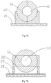
FIG. 4a is a schematic view of a movable member located in a second position, wherein the first connecting surface is inclined to the first junction surface. -
FIG. 4b a schematic view of a movable member located in a second position, wherein a recess of the movable member and a protrusion of the reflector are engaged in a form-fitting manner. -
FIG. 5a is a schematic view of another embodiment of the movable member, wherein the movable member is partially embedded into a gate. -
FIG. 5b is a schematic view of another embodiment of the movable member, wherein a driving assembly includes a supporting frame. -
FIG. 6 is a schematic view of a second embodiment of the present disclosure. -
FIG. 7 is a schematic view of a third embodiment of the present disclosure. -
FIG.8 is a schematic view of a fourth embodiment of the present disclosure. - Neutron capture therapy (NCT) has been increasingly practiced as an effective cancer curing means in recent years, and BNCT is the most common. Neutrons for NCT may be supplied by nuclear reactors or accelerators. Take AB-BNCT for example, its principal components include, in general, an accelerator for accelerating charged particles (such as protons and deuterons), a target, a heat removal system and a beam shaping assembly. The accelerated charged particles interact with the metal target to produce the neutrons, and suitable nuclear reactions are always determined according to such characteristics as desired neutron yield and energy, available accelerated charged particle energy and current and materialization of the metal target, among which the most discussed two are 7Li (p, n) 7Be and 9Be (p, n) 9B and both are endothermic reaction. Their energy thresholds are 1.881MeV and 2.055MeV respectively. Epithermal neutrons at a keV energy level are considered ideal neutron sources for BNCT. Theoretically, bombardment with lithium target using protons with energy slightly higher than the thresholds may produce neutrons relatively low in energy, so the neutrons may be used clinically without many moderations. However, Li (lithium) and Be (beryllium) and protons of threshold energy exhibit not high action cross section. In order to produce sufficient neutron fluxes, high-energy protons are usually selected to trigger the nuclear reactions.
- The target, considered perfect, is supposed to have the advantages of high neutron yield, a produced neutron energy distribution near the epithermal neutron energy range (see details thereinafter), little strong-penetration radiation, safety, low cost, easy accessibility, and high temperature resistance etc. But in reality, no nuclear reactions may satisfy all requests, the neutron generator is certainly damaged after being subjected to the impact and radiation of the accelerated protons, and further, the neutron generator has a quite important influence on the quality of neutron beams, so replacing the neutron generator periodically or according to the damaged condition of the neutron generator is quite necessary. A neutron capture therapy system with a replaceable neutron generator is described as below.
-
FIG. 1 is a schematic view of the neutroncapture therapy system 100 according to the present disclosure. The neutroncapture therapy system 100 includes abeam shaping assembly 10 and a drivingassembly 20. - The
beam shaping assembly 10 includes abeam inlet 11, aneutron generator 12, amoderator 13 adjacent to theneutron generator 12, areflector 14 surrounding theneutron generator 12 and themoderator 13, and abeam outlet 15. The proton beams enter into thebeam inlet 11 and have nuclear reaction with theneutron generator 12 to generate neutrons, themoderator 13 moderates the neutrons generated by theneutron generator 12, and thereflector 14 leads deflected neutrons back to themoderator 13 so as to improve the intensity of epithermal neutron beams. - The
reflector 14 includes at least onemovable member 16 capable of moving away from or close to theneutron generator 12. Themovable member 16 moves between a first position L1 and a second position L2 (refer toFIG. 2a andFIG. 2b ). When themovable member 16 is located in the first position LI, theneutron generator 12 is replaceable; and when themovable member 16 is located in the second position L2, theneutron generator 12 is irreplaceable. Specifically, when themovable member 16 moves away from theneutron generator 12 to the first position LI, theneutron generator 12 is exposed out of thebeam shaping assembly 10, and theneutron generator 12 can be taken out to be replaced; and after anew neutron generator 12 is mounted in thebeam shaping assembly 10, themovable member 16 moves close to theneutron generator 12 and located at the second position L2 (the movable member surrounds theneutron generator 12, so that theneutron generator 12 is irreplaceable), and then both themovable member 16 and thereflector 14 lead the deflected neutrons back to themoderator 13 in the subsequent neutron capture therapy process. - The
movable member 16 may be a part of the reflector or a combination of part of the reflector and part of the moderator. When themovable member 16 is a part of the reflector, theneutron generator 12 is arranged in front of themoderator 13 and is surrounded by thereflector 14, themoderator 13 is adjacent to the rear portion of theneutron generator 12, at this moment, only part of the reflector needs to be arranged as a movable structure (named the movable member), and the neutron generator is replaced after the movable member moves away from the neutron generator. When themovable member 16 is a combination of a part of the reflector and a part of the moderator, one part of theneutron generator 12 is located in front of themoderator 13 and is surrounded by thereflector 14, and the other part of theneutron generator 12 is embedded into themoderator 13 and is surrounded by themoderator 13, and at this moment, in order to replace theneutron generator 12, part of the reflector and part of the moderator surroundingneutron generator 12 need to be arranged as movable structure (named the movable member), and theneutron generator 12 is replaceable. - Referring to
FIG. 3a and FIG. 3b , for the convenience of the replacement of theneutron generator 12, preferably, themovable member 16 is a symmetrical member. The symmetrical member is provided with a symmetry plane A, the symmetrical member is symmetric with respect to the symmetry plane A, and the symmetry plane A passes through an axis I of theneutron generator 12. Thereflector 14 defines a first linear height H1, themovable member 16 defines a second linear height H2, theneutron generator 12 defines a third linear height H3, and the second linear height H2 is smaller than or equal to the first linear height H1 and is greater than the third linear height H3. - Referring to
FIG. 4a and FIG. 4b , thereflector 14 is further provided with a first connectingpart 140, and themovable member 16 is provided with a second connectingpart 160. The first connectingpart 140 is provided with a first connectingsurface 141 and afirst junction surface 142 connected to the first connectingsurface 141, and the second connectingpart 160 is provided with a second connectingsurface 161 andsecond junction surface 162 connected with the second connectingsurface 161. - When the second linear height H2 is smaller than the first linear height H1 and is greater than the third linear height H3, the first connecting
surface 141 and thefirst junction surface 142 are overlapped, the second connectingsurface 161 and thesecond junction surface 162 are overlapped, thesecond junction surface 162 is connected with thefirst junction surface 142 and are overlapped with a optional plane where the axis of theneutron generator 12 is located (please refer toFIG. 3a ). In this example, themovable member 16 is a part of thereflector 14. In this situation, when themovable member 16 moves away from theneutron generator 12 to the first position LI, a notch is formed in thereflector 14 by themovable member 16, and theneutron generator 12 is exposed out of the notch, and theneutron generator 12 is replaced at the notch; and when themovable member 16 moves close to theneutron generator 12 to the second position L2, themovable member 16 surrounds theneutron generator 12, and themovable member 16 and thereflector 14 lead the deflected neutrons back to the moderator in the subsequent neutron capture therapy process. - When the second linear height H2 of the
movable member 16 is equal to the first linear height H1 of thereflector 14, themovable member 16 is half of thereflector 14 surrounding theneutron generator 12. To reduce particles or radiation leaked at the connecting positions of themovable member 16 and thereflector 14 in the subsequent neutron capture therapy process, preferably, the first connectingsurface 141 and thefirst junction surface 142 of thereflector 14 are located in different planes, the second connectingsurface 161 and thesecond junction surface 162 of themovable member 16 is located in different planes, the first connectingsurface 141 and the second connectingsurface 161 are engaged, and thefirst junction surface 142 and thesecond junction surface 162 are engaged. The first connectingpart 140 and the second connectingpart 160 are specifically arranged as below (please refer toFIG. 4a ): the second connectingsurface 161 is inclined to thesecond junction surface 162; thefirst junction surface 142 is inclined to the first connectingsurface 141. When themovable member 16 surrounds theneutron generator 12, thesecond junction surface 162 and thefirst junction surface 142 are engaged, and the second connectingsurface 161 and the first connectingsurface 141 are engaged. The first connectingpart 140 and the second connectingpart 160 are also be arranged as below (please refer toFIG. 4b ): thesecond junction surface 162 includes a recess concavely formed in the second connectingsurface 161, and thefirst junction surface 142 includes a protrusion protruding out of the first connectingsurface 141, and when themovable member 16 surrounds theneutron generator 12, the recess and the protrusion are engaged in a form-fitting manner. - The structure of the driving
assembly 20 is described in detail as below. In addition, since the structure of themovable member 16 is already described above in detail, the description is not repeated hereinafter. During actual application, the structure of themovable member 16 as described above can be combined with the drivingassembly 20 described below. Though an embodiment described below is illustrated based on the reflector provided with the two movable members, one movable member can also be used if the onemovable member 16 can realize the replacement of theneutron generator 12. - A first embodiment of the present disclosure is also shown in
FIG. 2a andFIG. 2b , and is described based on thereflector 14 provided with the two movable members 16 (namely a firstmovable member 163 and a second movable member 164) located on the two sides of theneutron generator 12 and mutually connected. The drivingassembly 20 includes aguide rail 21 arranged outside thebeam shaping assembly 10 andgates 22 used for supporting themovable members 16, and thegates 22 move in theguide rail 21 to drive themovable members 16 to move away from or close to theneutron generator 12. Themovable members 16 include the firstmovable member 163 and the secondmovable member 164, thegates 22 include afirst gate 221 and asecond gate 222 which can move along theguide rail 21, thefirst gate 221 supports the firstmovable member 163, and thesecond gate 222 supports the secondmovable member 164. Thefirst gate 221 and thesecond gate 222 move in theguide rail 21 to drive the firstmovable member 163 and the secondmovable member 164 to move away from or close to theneutron generator 12 correspondingly. When both thefirst gate 221 and thesecond gate 222 move away from thebeam shaping assembly 10 to the first positions LI, the firstmovable member 163 and the secondmovable member 164 also move away from theneutron generator 12, and theneutron generator 12 is exposed out of thebeam shaping assembly 10 and can be replaced; and when both thefirst gate 221 and thesecond gate 222 move close to theneutron generator 12 to the second positions L2, the firstmovable member 163 and the secondmovable member 164 also move close to theneutron generator 12 until the firstmovable member 163 and the secondmovable member 164 surround theneutron generator 12, and the firstmovable member 163 and the secondmovable member 164 are used for leading the deflected neutrons back in the subsequent neutron capture therapy process. - To simplify the structural design, preferably, the first
movable member 163 and the secondmovable member 164 are the same in structure, and thefirst gate 221 and thesecond gate 222 are also the same in structure. To simplify the introduction hereinafter, both the firstmovable member 163 and the secondmovable member 164 are called themovable member 16, and both thefirst gate 221 and thesecond gate 222 are called thegate 22. - The
gates 22 can be of various structures. In the present embodiment, when the second linear height H2 of themovable member 16 is equal to the first linear height H1 of thereflector 14, thegates 22 surround themovable members 16, themovable members 16 can be considered to be embedded into thegates 22, motion of thegates 22 in theguide rail 21 is equivalent to opening-closing motion of thegates 22, and themovable members 16 get away from or close to theneutron generator 12 as thegates 22 are opened and closed. Preferably, thegates 22 are made of concrete. For sure, in order to save space or cost, half or even a smaller part of themovable members 16 can be embedded into the gates 22 (please refer toFIG. 5a ) as long as thegates 22 of this design can support themovable members 16 and can drive themovable members 16 to move away from or close to theneutron generator 12. When the second linear height H2 of themovable members 16 is smaller than the first linear height H1 of thereflector 14, supportingframes 23 can further be arranged between thegates 22 and the guide rail 21 (please refer toFIG. 5b ). One ends of the supportingframes 23 are fixed to thegates 22, and the other ends of the supportingframes 23 move in theguide rail 21 to get away from or close to thebeam shaping assembly 10. Themovable members 16 move away from or close to theneutron generator 12 as thegates 22 move along theguide rail 21. That is, thegates 22 are driven to move by means of movement of the supportingframes 23 in theguide rail 21, so that thegates 22 need to be designed into a sufficiently large size to move directly in theguide rail 21 is avoided, and accordingly the size of thegates 22 is reduced. -
FIG. 6 is a schematic view of a second embodiment of the present disclosure. A drivingassembly 20 includes a rotating member 24 (such as a shaft) and gates 22' fixedly held to the rotatingmember 24. The rotatingmember 24 is located under abeam shaping assembly 10, and an axis of the rotatingmember 24 is parallel to that of aneutron generator 12. The gates 22' rotate up and down around the rotatingmember 24. When the gates 22' move downwards, the gates 22' drivemovable members 16 to move away from theneutron generator 12, theneutron generator 12 is exposed out, and theneutron generator 12 can be replaced; and when the gates 22' rotate upwards, the gates 22' drive themovable members 16 to move close to theneutron generator 12, and themovable members 16 surround theneutron generator 12, and is used for leading the deflected neutrons back in the subsequent neutron capture therapy process. -
FIG. 7 is a schematic view of a third embodiment of the present disclosure. A drivingassembly 20 in the present embodiment includes first connectingrods 25 fixed to the outside of thebeam shaping assembly 10, second connectingrods 26 connected tomovable members 16, and third connectingrods 27 enable the first connectingrods 25 and the second connectingrods 26 to be connected, the third connectingrods 27 move to drive the second connectingrods 26 to move, and themovable members 16 move away from or close to theneutron generator 12 as the second connectingrods 26 move. -
FIG. 8 is a schematic view of a fourth embodiment of the present disclosure. When the second linear height H2 ofmovable members 16 is smaller than a first linear height H1 of the reflector 14 (particularly when the second linear height H2 of themovable members 16 is smaller than a third linear height H3 of a neutron generator 12), theguide rail 28 can be arranged in thereflector 14, and handles 165 can be arranged on the outer surfaces of themovable members 16, so that themovable members 16 are driven to move along theguide rail 28 to get away from or close to theneutron generator 12 by pulling and pushing thehandles 165. Certainly, the driving assemblies in the first embodiment to the third embodiment can also be applied to the fourth embodiment for replacing the handles, which is not described in detail here. - The invention is defined in the following claims; other embodiments, examples etc. being provided for illustrative purposes only.
Claims (11)
- A neutron capture therapy system (100), comprising a beam shaping assembly (10), wherein the beam shaping assembly comprises:a beam inlet (11);a neutron generator (12) arranged into the beam shaping assembly, wherein the neutron generator has nuclear reaction with an incident proton beam from the beam inlet to produce neutrons;a moderator (13) adjacent to the neutron generator, wherein the neutrons are moderated by the moderator to epithermal neutron energies;a reflector (14) surrounding the neutron generator and the moderator, wherein the reflector leads the deflected neutrons back to enhance the epithermal neutron beam intensity;a beam outlet (15); andat least one movable member (16) moving away from or close to the neutron generator, wherein the movable member moves between a first position (L1) and a second position (L2), wherein when the movable member is at the first position, the neutron generator is replaceable; and when the movable member is at the second position, the neutron generator is irreplaceable; characterized in thatthe reflector includes a first connecting part (140), the movable member includes a second connecting part (160), wherein when the movable member is at the first position, the first connecting part and the second connecting part are separated; when the movable member is at the second position, the first connecting part and the second connecting part are connected.
- The neutron capture therapy system according to Claim 1, wherein the movable part is part of the reflector or a combination of part of the reflector and part of the moderator.
- The neutron capture therapy system according to Claim 1, wherein the movable part defines a symmetry plane (A), the movable member is symmetrical with respect to the symmetry plane; the neutron generator defines an axis (I), the symmetry plane passes through the axis of the neutron generator, the reflector defines a first linear height (H1), the movable member defines a second linear height (H2), the neutron generator defines a third linear height (H3), and the second linear height is smaller than or equal to the first linear height and is greater than the third linear height.
- The neutron capture therapy system according to Claim 2, wherein the first connecting part comprises a first connecting surface (141) and a first junction surface (142); the second connecting part comprises a second connecting surface (161) and a second junction surface (162); and when the second linear height of the movable member is smaller than the first linear height of the reflector and is greater than the third linear height of the neutron generator, the first connecting surface and the first junction surface are overlapped, the second connecting surface and the second junction surface are overlapped, the second junction surface is connected with the first junction surface, and the second junction surface is overlapped with an optional plane where the axis of the neutron generator is in.
- The neutron capture therapy system according to Claim 2, wherein the first connecting part comprises a first connecting surface (141) and a first junction surface (142); the second connecting part comprises a second connecting surface (161) and a second junction surface (162); and when the second linear height of the movable member is equal to the first linear height of the reflector, the first connecting surface and the first junction surface are connected but are located in different planes, the second connecting surface and the second junction surface are connected but are located in different planes, the first connecting surface and the second connecting surface are connected, and the first junction surface and the second junction surface are connected.
- The neutron capture therapy system according to Claim 1, further comprising a driving assembly (20); the driving assembly comprises at least one gate (22) for supporting the movable member, and a guide rail (21) for allowing the gate to move away from or close to the neutron generator; wherein the gate moves away from or close to the beam shaping assembly along the guide rail, and when the gate moves away from the beam shaping assembly, the movable member moves away from the neutron generator; and when the gate moves close to the beam shaping assembly, the movable member moves close to the neutron generator.
- The neutron capture therapy system according to Claim 6, wherein the guide rail is arranged outside the beam shaping assembly, the driving assembly further comprises at least a supporting frame (23), one end of the supporting frame supports the gate, the other end of the supporting frame moves in the guide rail, wherein the gate moves away from or close to the beam shaping assembly as the supporting frame moves along the guide rail.
- The neutron capture therapy system according to Claim 1, wherein the neutron capture therapy system further comprises a driving assembly (20); the driving assembly comprises at least one gate (22) and a rotating member (24) for supporting the gate and allowing the gate to rotate; wherein the gate supports the movable member, and wherein when the gate rotates upwards around the rotating member, the movable member moves close to the neutron generator; and when the gate rotates downwards around the rotating member, the movable member moves away from the neutron generator.
- The neutron capture therapy system according to Claim 1, further comprising a driving assembly (20); the driving assembly comprises a first connecting rod (25), a second connecting rod (26), and a third connecting rod (27) enabling the first connecting rod and the second connecting rod to be connected; the first connecting rod is fixed to the outside of the beam shaping assembly; and one end of the second connecting rod is fixed to the movable member while the other end of the second connecting rod is connected to the first connecting rod, the first connecting rod drives the third connecting rod to move, and the third connecting rod drives the second connecting rod to move, so that the movable member moves away from or close to the neutron generator.
- The neutron capture therapy system according to Claim 2, wherein when the second linear height of the movable member is smaller than the first linear height of the reflector and is greater than the third linear height of the neutron generator, a guide rail (28) is arranged in the reflector, and the movable member is mounted in the beam shaping assembly and moves away from or close to the neutron generator along the guide rail.
- The neutron capture therapy system according to Claim 1, wherein the first connecting part comprises a first connecting surface (141) and a first junction surface (142) connected to the first connecting surface; the second connecting part comprises a second connecting surface (161) and a second junction surface (162) connected to the second connecting surface, wherein when the movable member is at the second position, the first connecting surface is connected with the second connecting surface, and the first junction surface is connected with the second junction surface.
Applications Claiming Priority (4)
| Application Number | Priority Date | Filing Date | Title |
|---|---|---|---|
| CN201520901136.XU CN205235192U (en) | 2015-11-12 | 2015-11-12 | Neutron capture treatment system |
| CN201510770609.1A CN106474633B (en) | 2015-11-12 | 2015-11-12 | Neutron capture treatment system |
| EP16863521.7A EP3357536B1 (en) | 2015-11-12 | 2016-10-18 | Neutron capture therapy system |
| PCT/CN2016/102332 WO2017080344A1 (en) | 2015-11-12 | 2016-10-18 | Neutron capture therapy system |
Related Parent Applications (2)
| Application Number | Title | Priority Date | Filing Date |
|---|---|---|---|
| EP16863521.7A Division EP3357536B1 (en) | 2015-11-12 | 2016-10-18 | Neutron capture therapy system |
| EP16863521.7A Division-Into EP3357536B1 (en) | 2015-11-12 | 2016-10-18 | Neutron capture therapy system |
Publications (2)
| Publication Number | Publication Date |
|---|---|
| EP3586922A1 EP3586922A1 (en) | 2020-01-01 |
| EP3586922B1 true EP3586922B1 (en) | 2020-12-09 |
Family
ID=58695891
Family Applications (2)
| Application Number | Title | Priority Date | Filing Date |
|---|---|---|---|
| EP19187968.3A Active EP3586922B1 (en) | 2015-11-12 | 2016-10-18 | Neutron capture therapy system |
| EP16863521.7A Active EP3357536B1 (en) | 2015-11-12 | 2016-10-18 | Neutron capture therapy system |
Family Applications After (1)
| Application Number | Title | Priority Date | Filing Date |
|---|---|---|---|
| EP16863521.7A Active EP3357536B1 (en) | 2015-11-12 | 2016-10-18 | Neutron capture therapy system |
Country Status (6)
| Country | Link |
|---|---|
| US (1) | US10898731B2 (en) |
| EP (2) | EP3586922B1 (en) |
| JP (1) | JP6830483B2 (en) |
| RU (1) | RU2717364C1 (en) |
| TW (1) | TWM541312U (en) |
| WO (1) | WO2017080344A1 (en) |
Families Citing this family (12)
| Publication number | Priority date | Publication date | Assignee | Title |
|---|---|---|---|---|
| JP6722755B2 (en) | 2015-05-06 | 2020-07-15 | ニュートロン・セラピューティクス・インコーポレイテッドNeutron Therapeutics Inc. | Neutron target for boron neutron capture therapy |
| JP6722281B2 (en) * | 2015-09-30 | 2020-07-15 | 南京中硼▲聯▼康医▲療▼科技有限公司Neuboron Medtech Ltd. | Beam shaper used for neutron capture therapy |
| US10462893B2 (en) | 2017-06-05 | 2019-10-29 | Neutron Therapeutics, Inc. | Method and system for surface modification of substrate for ion beam target |
| CN110913953A (en) | 2017-08-15 | 2020-03-24 | 西屋电气有限责任公司 | Neutron flux activated high energy therapeutic charged particle generation system by surgical localization |
| RU2743972C1 (en) | 2017-08-24 | 2021-03-01 | Нойборон Медтех Лтд. | Neutron capture therapy system |
| CN109464749B (en) * | 2017-09-07 | 2024-02-23 | 南京中硼联康医疗科技有限公司 | Neutron capture therapy system |
| EP3708224B1 (en) * | 2017-12-15 | 2022-04-06 | Neuboron Medtech Ltd. | Neutron capture therapy system |
| CN111714786A (en) | 2019-03-18 | 2020-09-29 | 中硼(厦门)医疗器械有限公司 | Neutron capture therapy system |
| CN111821580A (en) * | 2019-04-17 | 2020-10-27 | 中硼(厦门)医疗器械有限公司 | Neutron capture therapy system and beam shaper for neutron capture therapy system |
| US11517769B2 (en) * | 2019-07-10 | 2022-12-06 | Ricoh Company, Ltd. | Neutron beam transmission adjusting device comprising a neutron beam transmission unit including a neutron reactant, method for producing neutron beam transmission adjusting device, and neutron beam adjusting method |
| CN112755406A (en) * | 2019-10-21 | 2021-05-07 | 中硼(厦门)医疗器械有限公司 | Neutron capture therapy system and beam shaper installation method thereof |
| JP2022150626A (en) * | 2021-03-26 | 2022-10-07 | 住友重機械工業株式会社 | Treatment preparation equipment and treatment equipment |
Family Cites Families (13)
| Publication number | Priority date | Publication date | Assignee | Title |
|---|---|---|---|---|
| CN1569275A (en) * | 2004-04-29 | 2005-01-26 | 杭州华源伽玛医疗设备投资有限公司 | Gamma ray radiation device |
| JP4827054B2 (en) * | 2006-03-08 | 2011-11-30 | 三菱重工業株式会社 | Neutron generator and neutron irradiation system |
| JP5054335B2 (en) * | 2006-07-18 | 2012-10-24 | 株式会社日立製作所 | Medical device for boron neutron capture therapy |
| RU2355305C1 (en) * | 2007-08-28 | 2009-05-20 | Николай Викторович Анисимов | Technique for examination of thoracic and abdominal organs by magnetic resonance imaging (mri) procedure |
| JP5178238B2 (en) * | 2008-02-27 | 2013-04-10 | 住友重機械工業株式会社 | Target recovery device |
| JP5490651B2 (en) * | 2010-09-01 | 2014-05-14 | 住友重機械工業株式会社 | Neutron beam irradiation system |
| US20120330084A1 (en) * | 2011-06-27 | 2012-12-27 | Richard Harris Pantell | Neutron Source for Neutron Capture Therapy |
| PL3032926T3 (en) * | 2014-12-08 | 2017-07-31 | Neuboron Medtech Ltd. | A beam shaping assembly for neutron capture therapy |
| WO2016177270A1 (en) * | 2015-05-04 | 2016-11-10 | 南京中硼联康医疗科技有限公司 | Beam shaping body for neutron capture therapy |
| JP6722281B2 (en) * | 2015-09-30 | 2020-07-15 | 南京中硼▲聯▼康医▲療▼科技有限公司Neuboron Medtech Ltd. | Beam shaper used for neutron capture therapy |
| CN205235192U (en) * | 2015-11-12 | 2016-05-18 | 南京中硼联康医疗科技有限公司 | Neutron capture treatment system |
| WO2017088606A1 (en) * | 2015-11-26 | 2017-06-01 | 南京中硼联康医疗科技有限公司 | Beam shaping body for neutron capture therapy |
| JP2019502455A (en) * | 2016-01-08 | 2019-01-31 | 南京中硼▲聯▼康医▲療▼科技有限公司Neuboron Medtech Ltd. | Beam shaped body for neutron capture therapy |
-
2016
- 2016-10-18 RU RU2019113042A patent/RU2717364C1/en active
- 2016-10-18 WO PCT/CN2016/102332 patent/WO2017080344A1/en active Application Filing
- 2016-10-18 EP EP19187968.3A patent/EP3586922B1/en active Active
- 2016-10-18 JP JP2018523819A patent/JP6830483B2/en active Active
- 2016-10-18 EP EP16863521.7A patent/EP3357536B1/en active Active
- 2016-11-10 TW TW105217113U patent/TWM541312U/en unknown
-
2018
- 2018-05-01 US US15/967,727 patent/US10898731B2/en active Active
Non-Patent Citations (1)
| Title |
|---|
| None * |
Also Published As
| Publication number | Publication date |
|---|---|
| JP6830483B2 (en) | 2021-02-17 |
| WO2017080344A1 (en) | 2017-05-18 |
| JP2018534070A (en) | 2018-11-22 |
| EP3357536A4 (en) | 2018-10-17 |
| EP3357536A1 (en) | 2018-08-08 |
| EP3586922A1 (en) | 2020-01-01 |
| TWM541312U (en) | 2017-05-11 |
| EP3357536B1 (en) | 2019-09-11 |
| US20180243587A1 (en) | 2018-08-30 |
| US10898731B2 (en) | 2021-01-26 |
| RU2717364C1 (en) | 2020-03-23 |
Similar Documents
| Publication | Publication Date | Title |
|---|---|---|
| EP3586922B1 (en) | Neutron capture therapy system | |
| EP3395404B1 (en) | Beam shaper for neutron capture therapy | |
| US10898733B2 (en) | Beam shaping assembly for neutron capture therapy | |
| EP3032926B1 (en) | A beam shaping assembly for neutron capture therapy | |
| EP3456382B1 (en) | Neutron therapy device | |
| US11813483B2 (en) | Neutron capture therapy system | |
| US20200147414A1 (en) | Neutron capture therapy system | |
| CN107569781B (en) | Neutron capture therapy system | |
| CN205235192U (en) | Neutron capture treatment system | |
| US9215790B2 (en) | Formation of multiple proton beams using particle accelerator and stripper elements | |
| US20240139546A1 (en) | Neutron capture therapy system | |
| US20220409933A1 (en) | Neutron capture therapy system | |
| CN109925613B (en) | Neutron capture therapeutic device | |
| CN109925611B (en) | Neutron capture therapeutic device | |
| Mokhov | High-intensity beam collimation and targetry | |
| Bauer et al. | The FRG Project for a High-Power Spallation Neutron Source for Fundamental Research | |
| Vetter | NEUTRON SOURCE FOR FUNDAMENTAL RESEARCH |
Legal Events
| Date | Code | Title | Description |
|---|---|---|---|
| PUAI | Public reference made under article 153(3) epc to a published international application that has entered the european phase |
Free format text: ORIGINAL CODE: 0009012 |
|
| STAA | Information on the status of an ep patent application or granted ep patent |
Free format text: STATUS: THE APPLICATION HAS BEEN PUBLISHED |
|
| AC | Divisional application: reference to earlier application |
Ref document number: 3357536 Country of ref document: EP Kind code of ref document: P |
|
| AK | Designated contracting states |
Kind code of ref document: A1 Designated state(s): AL AT BE BG CH CY CZ DE DK EE ES FI FR GB GR HR HU IE IS IT LI LT LU LV MC MK MT NL NO PL PT RO RS SE SI SK SM TR |
|
| STAA | Information on the status of an ep patent application or granted ep patent |
Free format text: STATUS: REQUEST FOR EXAMINATION WAS MADE |
|
| 17P | Request for examination filed |
Effective date: 20200305 |
|
| RBV | Designated contracting states (corrected) |
Designated state(s): AL AT BE BG CH CY CZ DE DK EE ES FI FR GB GR HR HU IE IS IT LI LT LU LV MC MK MT NL NO PL PT RO RS SE SI SK SM TR |
|
| GRAP | Despatch of communication of intention to grant a patent |
Free format text: ORIGINAL CODE: EPIDOSNIGR1 |
|
| STAA | Information on the status of an ep patent application or granted ep patent |
Free format text: STATUS: GRANT OF PATENT IS INTENDED |
|
| INTG | Intention to grant announced |
Effective date: 20200508 |
|
| GRAS | Grant fee paid |
Free format text: ORIGINAL CODE: EPIDOSNIGR3 |
|
| GRAA | (expected) grant |
Free format text: ORIGINAL CODE: 0009210 |
|
| STAA | Information on the status of an ep patent application or granted ep patent |
Free format text: STATUS: THE PATENT HAS BEEN GRANTED |
|
| AC | Divisional application: reference to earlier application |
Ref document number: 3357536 Country of ref document: EP Kind code of ref document: P |
|
| AK | Designated contracting states |
Kind code of ref document: B1 Designated state(s): AL AT BE BG CH CY CZ DE DK EE ES FI FR GB GR HR HU IE IS IT LI LT LU LV MC MK MT NL NO PL PT RO RS SE SI SK SM TR |
|
| REG | Reference to a national code |
Ref country code: GB Ref legal event code: FG4D |
|
| REG | Reference to a national code |
Ref country code: AT Ref legal event code: REF Ref document number: 1342781 Country of ref document: AT Kind code of ref document: T Effective date: 20201215 Ref country code: CH Ref legal event code: EP |
|
| REG | Reference to a national code |
Ref country code: DE Ref legal event code: R096 Ref document number: 602016049713 Country of ref document: DE |
|
| REG | Reference to a national code |
Ref country code: IE Ref legal event code: FG4D |
|
| PG25 | Lapsed in a contracting state [announced via postgrant information from national office to epo] |
Ref country code: GR Free format text: LAPSE BECAUSE OF FAILURE TO SUBMIT A TRANSLATION OF THE DESCRIPTION OR TO PAY THE FEE WITHIN THE PRESCRIBED TIME-LIMIT Effective date: 20210310 Ref country code: NO Free format text: LAPSE BECAUSE OF FAILURE TO SUBMIT A TRANSLATION OF THE DESCRIPTION OR TO PAY THE FEE WITHIN THE PRESCRIBED TIME-LIMIT Effective date: 20210309 Ref country code: RS Free format text: LAPSE BECAUSE OF FAILURE TO SUBMIT A TRANSLATION OF THE DESCRIPTION OR TO PAY THE FEE WITHIN THE PRESCRIBED TIME-LIMIT Effective date: 20201209 Ref country code: FI Free format text: LAPSE BECAUSE OF FAILURE TO SUBMIT A TRANSLATION OF THE DESCRIPTION OR TO PAY THE FEE WITHIN THE PRESCRIBED TIME-LIMIT Effective date: 20201209 |
|
| REG | Reference to a national code |
Ref country code: AT Ref legal event code: MK05 Ref document number: 1342781 Country of ref document: AT Kind code of ref document: T Effective date: 20201209 |
|
| PG25 | Lapsed in a contracting state [announced via postgrant information from national office to epo] |
Ref country code: LV Free format text: LAPSE BECAUSE OF FAILURE TO SUBMIT A TRANSLATION OF THE DESCRIPTION OR TO PAY THE FEE WITHIN THE PRESCRIBED TIME-LIMIT Effective date: 20201209 Ref country code: SE Free format text: LAPSE BECAUSE OF FAILURE TO SUBMIT A TRANSLATION OF THE DESCRIPTION OR TO PAY THE FEE WITHIN THE PRESCRIBED TIME-LIMIT Effective date: 20201209 Ref country code: BG Free format text: LAPSE BECAUSE OF FAILURE TO SUBMIT A TRANSLATION OF THE DESCRIPTION OR TO PAY THE FEE WITHIN THE PRESCRIBED TIME-LIMIT Effective date: 20210309 |
|
| REG | Reference to a national code |
Ref country code: NL Ref legal event code: MP Effective date: 20201209 |
|
| PG25 | Lapsed in a contracting state [announced via postgrant information from national office to epo] |
Ref country code: HR Free format text: LAPSE BECAUSE OF FAILURE TO SUBMIT A TRANSLATION OF THE DESCRIPTION OR TO PAY THE FEE WITHIN THE PRESCRIBED TIME-LIMIT Effective date: 20201209 Ref country code: NL Free format text: LAPSE BECAUSE OF FAILURE TO SUBMIT A TRANSLATION OF THE DESCRIPTION OR TO PAY THE FEE WITHIN THE PRESCRIBED TIME-LIMIT Effective date: 20201209 |
|
| REG | Reference to a national code |
Ref country code: LT Ref legal event code: MG9D |
|
| PG25 | Lapsed in a contracting state [announced via postgrant information from national office to epo] |
Ref country code: EE Free format text: LAPSE BECAUSE OF FAILURE TO SUBMIT A TRANSLATION OF THE DESCRIPTION OR TO PAY THE FEE WITHIN THE PRESCRIBED TIME-LIMIT Effective date: 20201209 Ref country code: SK Free format text: LAPSE BECAUSE OF FAILURE TO SUBMIT A TRANSLATION OF THE DESCRIPTION OR TO PAY THE FEE WITHIN THE PRESCRIBED TIME-LIMIT Effective date: 20201209 Ref country code: SM Free format text: LAPSE BECAUSE OF FAILURE TO SUBMIT A TRANSLATION OF THE DESCRIPTION OR TO PAY THE FEE WITHIN THE PRESCRIBED TIME-LIMIT Effective date: 20201209 Ref country code: CZ Free format text: LAPSE BECAUSE OF FAILURE TO SUBMIT A TRANSLATION OF THE DESCRIPTION OR TO PAY THE FEE WITHIN THE PRESCRIBED TIME-LIMIT Effective date: 20201209 Ref country code: LT Free format text: LAPSE BECAUSE OF FAILURE TO SUBMIT A TRANSLATION OF THE DESCRIPTION OR TO PAY THE FEE WITHIN THE PRESCRIBED TIME-LIMIT Effective date: 20201209 Ref country code: RO Free format text: LAPSE BECAUSE OF FAILURE TO SUBMIT A TRANSLATION OF THE DESCRIPTION OR TO PAY THE FEE WITHIN THE PRESCRIBED TIME-LIMIT Effective date: 20201209 Ref country code: PT Free format text: LAPSE BECAUSE OF FAILURE TO SUBMIT A TRANSLATION OF THE DESCRIPTION OR TO PAY THE FEE WITHIN THE PRESCRIBED TIME-LIMIT Effective date: 20210409 |
|
| PG25 | Lapsed in a contracting state [announced via postgrant information from national office to epo] |
Ref country code: PL Free format text: LAPSE BECAUSE OF FAILURE TO SUBMIT A TRANSLATION OF THE DESCRIPTION OR TO PAY THE FEE WITHIN THE PRESCRIBED TIME-LIMIT Effective date: 20201209 Ref country code: AT Free format text: LAPSE BECAUSE OF FAILURE TO SUBMIT A TRANSLATION OF THE DESCRIPTION OR TO PAY THE FEE WITHIN THE PRESCRIBED TIME-LIMIT Effective date: 20201209 |
|
| REG | Reference to a national code |
Ref country code: DE Ref legal event code: R097 Ref document number: 602016049713 Country of ref document: DE |
|
| PG25 | Lapsed in a contracting state [announced via postgrant information from national office to epo] |
Ref country code: IS Free format text: LAPSE BECAUSE OF FAILURE TO SUBMIT A TRANSLATION OF THE DESCRIPTION OR TO PAY THE FEE WITHIN THE PRESCRIBED TIME-LIMIT Effective date: 20210409 |
|
| PLBE | No opposition filed within time limit |
Free format text: ORIGINAL CODE: 0009261 |
|
| STAA | Information on the status of an ep patent application or granted ep patent |
Free format text: STATUS: NO OPPOSITION FILED WITHIN TIME LIMIT |
|
| PG25 | Lapsed in a contracting state [announced via postgrant information from national office to epo] |
Ref country code: AL Free format text: LAPSE BECAUSE OF FAILURE TO SUBMIT A TRANSLATION OF THE DESCRIPTION OR TO PAY THE FEE WITHIN THE PRESCRIBED TIME-LIMIT Effective date: 20201209 |
|
| 26N | No opposition filed |
Effective date: 20210910 |
|
| PG25 | Lapsed in a contracting state [announced via postgrant information from national office to epo] |
Ref country code: DK Free format text: LAPSE BECAUSE OF FAILURE TO SUBMIT A TRANSLATION OF THE DESCRIPTION OR TO PAY THE FEE WITHIN THE PRESCRIBED TIME-LIMIT Effective date: 20201209 Ref country code: SI Free format text: LAPSE BECAUSE OF FAILURE TO SUBMIT A TRANSLATION OF THE DESCRIPTION OR TO PAY THE FEE WITHIN THE PRESCRIBED TIME-LIMIT Effective date: 20201209 |
|
| PG25 | Lapsed in a contracting state [announced via postgrant information from national office to epo] |
Ref country code: ES Free format text: LAPSE BECAUSE OF FAILURE TO SUBMIT A TRANSLATION OF THE DESCRIPTION OR TO PAY THE FEE WITHIN THE PRESCRIBED TIME-LIMIT Effective date: 20201209 |
|
| REG | Reference to a national code |
Ref country code: CH Ref legal event code: PL |
|
| PG25 | Lapsed in a contracting state [announced via postgrant information from national office to epo] |
Ref country code: IS Free format text: LAPSE BECAUSE OF FAILURE TO SUBMIT A TRANSLATION OF THE DESCRIPTION OR TO PAY THE FEE WITHIN THE PRESCRIBED TIME-LIMIT Effective date: 20210409 |
|
| REG | Reference to a national code |
Ref country code: BE Ref legal event code: MM Effective date: 20211031 |
|
| PG25 | Lapsed in a contracting state [announced via postgrant information from national office to epo] |
Ref country code: MC Free format text: LAPSE BECAUSE OF FAILURE TO SUBMIT A TRANSLATION OF THE DESCRIPTION OR TO PAY THE FEE WITHIN THE PRESCRIBED TIME-LIMIT Effective date: 20201209 |
|
| PG25 | Lapsed in a contracting state [announced via postgrant information from national office to epo] |
Ref country code: LU Free format text: LAPSE BECAUSE OF NON-PAYMENT OF DUE FEES Effective date: 20211018 Ref country code: BE Free format text: LAPSE BECAUSE OF NON-PAYMENT OF DUE FEES Effective date: 20211031 |
|
| PG25 | Lapsed in a contracting state [announced via postgrant information from national office to epo] |
Ref country code: LI Free format text: LAPSE BECAUSE OF NON-PAYMENT OF DUE FEES Effective date: 20211031 Ref country code: CH Free format text: LAPSE BECAUSE OF NON-PAYMENT OF DUE FEES Effective date: 20211031 |
|
| PG25 | Lapsed in a contracting state [announced via postgrant information from national office to epo] |
Ref country code: IE Free format text: LAPSE BECAUSE OF NON-PAYMENT OF DUE FEES Effective date: 20211018 |
|
| PG25 | Lapsed in a contracting state [announced via postgrant information from national office to epo] |
Ref country code: CY Free format text: LAPSE BECAUSE OF FAILURE TO SUBMIT A TRANSLATION OF THE DESCRIPTION OR TO PAY THE FEE WITHIN THE PRESCRIBED TIME-LIMIT Effective date: 20201209 |
|
| PG25 | Lapsed in a contracting state [announced via postgrant information from national office to epo] |
Ref country code: HU Free format text: LAPSE BECAUSE OF FAILURE TO SUBMIT A TRANSLATION OF THE DESCRIPTION OR TO PAY THE FEE WITHIN THE PRESCRIBED TIME-LIMIT; INVALID AB INITIO Effective date: 20161018 |
|
| PG25 | Lapsed in a contracting state [announced via postgrant information from national office to epo] |
Ref country code: MK Free format text: LAPSE BECAUSE OF FAILURE TO SUBMIT A TRANSLATION OF THE DESCRIPTION OR TO PAY THE FEE WITHIN THE PRESCRIBED TIME-LIMIT Effective date: 20201209 |
|
| PG25 | Lapsed in a contracting state [announced via postgrant information from national office to epo] |
Ref country code: TR Free format text: LAPSE BECAUSE OF FAILURE TO SUBMIT A TRANSLATION OF THE DESCRIPTION OR TO PAY THE FEE WITHIN THE PRESCRIBED TIME-LIMIT Effective date: 20201209 |
|
| PG25 | Lapsed in a contracting state [announced via postgrant information from national office to epo] |
Ref country code: MT Free format text: LAPSE BECAUSE OF FAILURE TO SUBMIT A TRANSLATION OF THE DESCRIPTION OR TO PAY THE FEE WITHIN THE PRESCRIBED TIME-LIMIT Effective date: 20201209 |
|
| PGFP | Annual fee paid to national office [announced via postgrant information from national office to epo] |
Ref country code: GB Payment date: 20240923 Year of fee payment: 9 |
|
| PGFP | Annual fee paid to national office [announced via postgrant information from national office to epo] |
Ref country code: DE Payment date: 20241022 Year of fee payment: 9 |
|
| PGFP | Annual fee paid to national office [announced via postgrant information from national office to epo] |
Ref country code: FR Payment date: 20241016 Year of fee payment: 9 |
|
| PGFP | Annual fee paid to national office [announced via postgrant information from national office to epo] |
Ref country code: IT Payment date: 20241031 Year of fee payment: 9 |