EP3547326B1 - Procédé permettant de détecter les particules provenant de la fumée évacuée par un patient, de régler la vitesse de la pompe en fonction des informations détectées et de communiquer les paramètres fonctionnels du système au moyeu - Google Patents
Procédé permettant de détecter les particules provenant de la fumée évacuée par un patient, de régler la vitesse de la pompe en fonction des informations détectées et de communiquer les paramètres fonctionnels du système au moyeu Download PDFInfo
- Publication number
- EP3547326B1 EP3547326B1 EP19165963.0A EP19165963A EP3547326B1 EP 3547326 B1 EP3547326 B1 EP 3547326B1 EP 19165963 A EP19165963 A EP 19165963A EP 3547326 B1 EP3547326 B1 EP 3547326B1
- Authority
- EP
- European Patent Office
- Prior art keywords
- surgical
- smoke
- evacuation system
- sensor
- fluid
- Prior art date
- Legal status (The legal status is an assumption and is not a legal conclusion. Google has not performed a legal analysis and makes no representation as to the accuracy of the status listed.)
- Active
Links
Images


Classifications
-
- G—PHYSICS
- G16—INFORMATION AND COMMUNICATION TECHNOLOGY [ICT] SPECIALLY ADAPTED FOR SPECIFIC APPLICATION FIELDS
- G16H—HEALTHCARE INFORMATICS, i.e. INFORMATION AND COMMUNICATION TECHNOLOGY [ICT] SPECIALLY ADAPTED FOR THE HANDLING OR PROCESSING OF MEDICAL OR HEALTHCARE DATA
- G16H40/00—ICT specially adapted for the management or administration of healthcare resources or facilities; ICT specially adapted for the management or operation of medical equipment or devices
- G16H40/60—ICT specially adapted for the management or administration of healthcare resources or facilities; ICT specially adapted for the management or operation of medical equipment or devices for the operation of medical equipment or devices
- G16H40/63—ICT specially adapted for the management or administration of healthcare resources or facilities; ICT specially adapted for the management or operation of medical equipment or devices for the operation of medical equipment or devices for local operation
Definitions
- Surgical smoke evacuators are configured to evacuate smoke, as well as fluid and/or particulate, from a surgical site. For example, during a surgical procedure involving an energy device, smoke can be generated at the surgical site.
- WO 2015/134749 A2 relates to a waste collection unit with a primary display on which information about the operation of the unit is presented.
- a primary display on which information about the operation of the unit is presented.
- the light assembly emits light of selectively colors or in a selected pattern based on an operation state of the waste collection unit.
- the present disclosure relates to energy devices and intelligent surgical evacuation systems for evacuating smoke and/or other fluids and/or particulates from a surgical site.
- Smoke is often generated during a surgical procedure that utilizes one or more energy devices.
- Energy devices use energy to affect tissue.
- the energy is supplied by a generator.
- Energy devices include devices with tissue-contacting electrodes, such as an electrosurgical device having one or more radio frequency (RF) electrodes, and devices with vibrating surfaces, such as an ultrasonic device having an ultrasonic blade.
- RF radio frequency
- a generator is configured to generate oscillating electric currents to energize the electrodes.
- a generator is configured to generate ultrasonic vibrations to energize the ultrasonic blade. Generators are further described herein.
- Ultrasonic energy can be utilized for coagulation and cutting tissue.
- Ultrasonic energy coagulates and cuts tissue by vibrating an energy-delivery surface (e.g. an ultrasonic blade) in contact with tissue.
- the ultrasonic blade can be coupled to a waveguide that transmits the vibrational energy from an ultrasonic transducer, which generates mechanical vibrations and is powered by a generator. Vibrating at high frequencies (e.g., 55,500 times per second), the ultrasonic blade generates friction and heat between the blade and the tissue, i.e. at the blade-tissue interface, which denatures the proteins in the tissue to form a sticky coagulum. Pressure exerted on the tissue by the blade surface collapses blood vessels and allows the coagulum to form a hemostatic seal.
- the precision of cutting and coagulation can be controlled by the clinician's technique and by adjusting the power level, blade edge, tissue traction, and blade pressure, for example.
- Ultrasonic surgical instruments are finding increasingly widespread applications in surgical procedures by virtue of the unique performance characteristics of such instruments.
- ultrasonic surgical instruments can provide substantially simultaneous cutting of tissue and hemostasis by coagulation, which can desirably minimize patient trauma.
- the cutting action is typically realized by an end effector, or blade tip, at the distal end of the ultrasonic instrument.
- the ultrasonic end effector transmits the ultrasonic energy to tissue brought into contact with the end effector.
- Ultrasonic instruments of this nature can be configured for open surgical use, laparoscopic surgical procedures, or endoscopic surgical procedures, including robotic-assisted procedures, for example.
- An electrosurgical device typically includes a handpiece and an instrument having a distally-mounted end effector (e.g., one or more electrodes).
- the end effector can be positioned against and/or adjacent to the tissue such that electrical current is introduced into the tissue. Electrosurgery is widely-used and offers many advantages including the use of a single surgical instrument for both coagulation and cutting.
- the electrode or tip of the electrosurgical device is small at the point of contact with the patient to produce an RF current with a high current density in order to produce a surgical effect of coagulating and/or cutting tissue through cauterization.
- the return electrode carries the same RF signal back to the electrosurgical generator after it passes through the patient, thus providing a return path for the RF signal.
- Electrosurgical devices can be configured for bipolar or monopolar operation.
- bipolar operation current is introduced into and returned from the tissue by active and return electrodes, respectively, of the end effector.
- monopolar operation current is introduced into the tissue by an active electrode of the end effector and returned through a return electrode (e.g., a grounding pad) separately located on or against a patient's body.
- Heat generated by the current flowing through the tissue may form hemostatic seals within the tissue and/or between tissues and, thus, may be particularly useful for sealing blood vessels, for example.
- the end effector of an electrosurgical device also may include a cutting member that is movable relative to the tissue and the electrodes to transect the tissue.
- an electrosurgical device can transmit low frequency RF current through tissue, which causes ionic agitation, or friction (in effect resistive heating), thereby increasing the temperature of the tissue. Because a boundary is created between the affected tissue and the surrounding tissue, clinicians can operate with a high level of precision and control, without sacrificing un-targeted adjacent tissue.
- the low operating temperature of RF energy is useful for removing, shrinking, or sculpting soft tissue while simultaneously sealing blood vessels.
- RF energy can work particularly well on connective tissue, which is primarily comprised of collagen and shrinks when contacted by heat.
- Other electrosurgical instruments include, without limitation, irreversible and/or reversible electroporation, and/or microwave technologies, among others. The techniques disclosed herein are applicable to ultrasonic, bipolar and/or monopolar RF (electrosurgical), irreversible and/or reversible electroporation, and/or microwave based surgical instruments, among others.
- Electrical energy applied by an electrosurgical device can be transmitted to the instrument from a generator.
- the generator is configured to convert electricity to high frequency waveforms comprised of oscillating electric currents, which are transmitted to the electrodes to affect tissue.
- the current passes through tissue to fulgurate (a form of coagulation in which a current arc over the tissue creates tissue charring), desiccate (a direct energy application that drives water of the cells), and/or cut (an indirect energy application that vaporizes cellular fluid causing cellular explosions) tissue.
- fulgurate a form of coagulation in which a current arc over the tissue creates tissue charring
- desiccate a direct energy application that drives water of the cells
- cut an indirect energy application that vaporizes cellular fluid causing cellular explosions
- the current waveform can be adjusted to affect a different surgical function and/or accommodate tissue of different properties.
- tissue vascular tissue, nerve tissue, muscles, skin, fat and/or bone-can respond differently to the same waveform.
- the electrical energy may be in the form of RF energy that may be in a frequency range described in EN 60601-2-2:2009+A11:2011, Definition 201.3.218-HIGH FREQUENCY.
- the frequencies in monopolar RF applications are typically restricted to less than 5 MHz to minimize the problems associated with high frequency leakage current. Frequencies above 200 kHz can be typically used for monopolar applications in order to avoid the unwanted stimulation of nerves and muscles that would result from the use of low frequency current.
- the frequency can be almost anything. Lower frequencies may be used for bipolar techniques in certain instances, such as if a risk analysis shows that the possibility of neuromuscular stimulation has been mitigated to an acceptable level. It is generally recognized that 10 mA is the lower threshold of thermal effects on tissue. Higher frequencies may also be used in the case of bipolar techniques.
- a generator can be configured to generate an output waveform digitally and provide it to a surgical device such that the surgical device may utilize the waveform for various tissue effects.
- the generator can be a monopolar generator, a bipolar generator, and/or an ultrasonic generator.
- a single generator can supply energy to a monopolar device, a bipolar device, an ultrasonic device, or a combination electrosurgery/ultrasonic device.
- the generator can promote tissue-specific effects via wave-shaping, and/or can drive RF and ultrasonic energy simultaneously and/or sequentially to a single surgical instrument or multiple surgical instruments.
- a surgical system can include a generator and various surgical instruments usable therewith, including an ultrasonic surgical instrument, an RF electrosurgical instrument, and a combination ultrasonic/RF electrosurgical instrument.
- the generator can be configurable for use with the various surgical instruments as further described in U.S. Patent Application No. 15/265,279, titled TECHNIQUES FOR OPERATING GENERATOR FOR DIGITALLY GENERATING ELECTRICAL SIGNAL WAVEFORMS AND SURGICAL INSTRUMENTS, filed September 14, 2016 , now U.S. Patent Application Publication No. 2017/0086914 ,
- RF electrical energy which is produced by a generator and transmitted to a patient's tissue through an electrode that is operated by a clinician.
- the electrode delivers an electrical discharge to cellular matter of the patient's body adjacent to the electrode. The discharge causes the cellular matter to heat up in order to cut tissue and/or cauterize blood vessels.
- thermal necrosis of the tissue adjacent to the electrode can cause thermal necrosis of the tissue adjacent to the electrode.
- the longer time at which tissue is exposed to the high temperatures involved with electrosurgery the more likely it is that the tissue will suffer thermal necrosis.
- thermal necrosis of the tissue can decrease the speed of cutting the tissue and increase post-operative complications, eschar production, and healing time, as well as increasing incidences of heat damage to the tissue positioned away from the cutting site.
- the concentration of the RF energy discharge affects both the efficiency with which the electrode is able to cut tissue and the likelihood of tissue damage away from the cutting site.
- the RF energy tends to be uniformly distributed over a relatively large area adjacent to the intended incision site.
- a generally uniform distribution of the RF energy discharge increases the likelihood of extraneous charge loss into the surrounding tissue, which may increase the likelihood of unwanted tissue damage in the surrounding tissue.
- Typical electrosurgical generators generate various operating frequencies of RF electrical energy and output power levels.
- the specific operating frequency and power output of a generator varies based upon the particular electrosurgical generator used and the needs of the physician during the electrosurgical procedure.
- the specific operating frequency and power output levels can be manually adjusted on the generator by a clinician or other operating room personnel. Properly adjusting these various settings requires great knowledge, skill, and attention from the clinician or other personnel. Once the clinician has made the desired adjustments to the various settings on the generator, the generator can maintain those output parameters during electrosurgery.
- wave generators used for electrosurgery are adapted to produce RF waves with an output power in the range of 1-300 W in a cut mode and 1-120 W in coagulation mode, and a frequency in the range of 300-600 kHz.
- Typical wave generators are adapted to maintain the selected settings during the electrosurgery. For example, if the clinician were to set the output power level of the generator to 50 W and then touch the electrode to the patient to perform electrosurgery, the power level of the generator would quickly rise to and be maintained at 50 W. While setting the power level to a specific setting, such as 50 W, will allow the clinician to cut through the patient's tissue, maintaining such a high power level increases the likelihood of thermal necrosis of the patient's tissue.
- a generator is configured to provide sufficient power to effectively perform electrosurgery in connection with an electrode that increases the concentration of the RF energy discharge, while at the same time limiting unwanted tissue damage, reducing post-operative complications, and facilitating quicker healing.
- the waveform from the generator can be optimized by a control circuit throughout the surgical procedure.
- energy devices delivery mechanical and/or electrical energy to target tissue in order to treat the tissue (e.g. to cut the tissue, cauterize blood vessels and/or coagulate the tissue within and/or near the targeted tissue).
- the cutting, cauterization, and/or coagulation of tissue can result in fluids and/or particulates being released into the air.
- Such fluids and/or particulates emitted during a surgical procedure can constitute smoke, for example, which can comprise carbon particles and/or other particles suspended in air.
- a fluid can comprise smoke and/or other fluidic matter. Approximately 90% of endoscopic and open surgical procedures generate some level of smoke.
- smoke generated during an electrosurgical procedure can contain toxic chemicals including acrolein, acetonitrile, acrylonitrile, acetylene, alkyl benzenes, benzene, butadiene, butene, carbon monoxide, creosols, ethane, ethylene, formaldehyde, free radicals, hydrogen cyanide, isobutene, methane, phenol, polycyclic aromatic hydrocarbons, propene, propylene, pyridene, pyrrole, styrene, toluene, and xylene, as well as dead and live cellular material (including blood fragments), and viruses.
- toxic chemicals including acrolein, acetonitrile, acrylonitrile, acetylene, alkyl benzenes, benzene, butadiene, butene, carbon monoxide, creosols, ethane, ethylene, formaldehyde, free radicals, hydrogen cyan
- the size of particulate matter in surgical smoke can be harmful to the respiratory system of the clinician(s), the assistant(s), and/or the patient(s).
- the particulates can be extremely small. Repeated inhalation of extremely small particulate matter can lead to acute and chronic respiratory conditions in certain instances.
- an evacuation system can be configured to evacuate smoke that is generated during an electrosurgical procedure.
- an evacuation system can be referred to as a "smoke evacuation system” though such evacuation systems can be configured to evacuate more than just smoke from a surgical site.
- the "smoke" evacuated by an evacuation system is not limited to just smoke. Rather, the smoke evacuation systems disclosed herein can be used to evacuate a variety of fluids, including liquids, gases, vapors, smoke, steam, or combinations thereon.
- the fluids can be biologic in origin and/or can be introduced to the surgical site from an external source during a procedure.
- the fluids can include water, saline, lymph, blood, exudate, and/or pyogenic discharge, for example.
- the fluids can include particulates or other matter (e.g. cellular matter or debris) that is evacuated by the evacuation system. For example, such particulates can be suspended in the fluid.
- Evacuation systems often include a pump and a filter.
- the pump creates suction that draws the smoke into the filter.
- suction can be configured to draw smoke from the surgical site into a conduit opening, through an evacuation conduit, and into an evacuator housing of the evacuation system.
- An evacuator housing 50018 for a surgical evacuation system 50000 is shown in FIG. 1 .
- a pump and a filter are positioned within the evacuator housing 50018.
- Smoke drawn into the evacuator housing 50018 travels to the filter via a suction conduit 50036, and harmful toxins and offensive smells are filtered out of the smoke as it moves through the filter.
- the suction conduit can also be referred to as vacuum and/or evacuation conduit and/or tube, for example. Filtered air may then exit the surgical evacuation system as exhaust.
- various evacuation systems disclosed herein can also be configured to deliver fluids to a desired location, such as a surgical site.
- the suction conduit 50036 from the evacuator housing 50018 may terminate at a hand piece, such as the handpiece 50032.
- the handpiece 50032 comprises an electrosurgical instrument that includes an electrode tip 50034 and an evacuation conduit opening near and/or adjacent to the electrode tip 50034.
- the evacuation conduit opening is configured to capture the fluid and/or particulates that are released during a surgical procedure.
- the evacuation system 50000 is integrated into the electrosurgical instrument 50032.
- smoke S is being pulled into the suction conduit 50036.
- the evacuation system 50000 can include a separate surgical tool that comprises a conduit opening and is configured to suck the smoke out into the system.
- a tool comprising the evacuation conduit and opening can be snap fit onto an electrosurgical tool as depicted in FIG. 3 .
- a portion of a suction conduit 51036 can be positioned around (or adjacent to) an electrode tip 51034.
- the suction conduit 51036 can be releasably secured to a handpiece 51032 of an electrosurgical tool comprising the electrode tip 51034 with clips or other fasteners.
- an evacuation system 50500 includes the evacuator housing 50518, a filter 50502, an exhaust mechanism 50520, and a pump 50506.
- the evacuation system 50500 defines a flow path 50504 through the evacuator housing 50518 having an inlet port 50522 and an outlet port 50524.
- the filter 50502, the exhaust mechanism 50520, and the pump 50506 are sequentially arranged in-line with the flow path 50504 through the evacuator housing 50518 between the inlet port 50522 and the outlet port 50524.
- the inlet port 50522 can be fluidically coupled to a suction conduit, such as the suction conduit 50036 in FIG. 1 , for example, which can comprise a distal conduit opening positionable at the surgical site.
- the pump 50506 is configured to produce a pressure differential in the flow path 50504 by a mechanical action.
- the pressure differential is configured to draw smoke 50508 from the surgical site into the inlet port 50522 and along the flow path 50504. After the smoke 50508 has moved through the filter 50502, the smoke 50508 can be considered to be filtered smoke, or air, 50510, which can continue through the flow path 50504 and is expelled through the outlet port 50524.
- the flow path 50504 includes a first zone 50514 and a second zone 50516.
- the first zone 50514 is upstream from the pump 50506; the second zone 50516 is downstream from the pump 50506.
- the pump 50506 is configured to pressurize the fluid in the flow path 50504 so that the fluid in the second zone 50516 has a higher pressure than the fluid in the first zone 50514.
- a motor 50512 drives the pump 50506.
- the exhaust mechanism 50520 is a mechanism that can control the velocity, the direction, and/or other properties of the filtered smoke 50510 exiting the evacuation system 50500 at the outlet port 50524.
- the flow path 50504 through the evacuation system 50500 can be comprised of a tube or other conduit that substantially contains and/or isolates the fluid moving through the flow path 50504 from the fluid outside the flow path 50504.
- the first zone 50514 of the flow path 50504 can comprise a tube through which the flow path 50504 extends between the filter 50502 and the pump 50506.
- the second zone 50516 of the flow path 50504 can also comprise a tube through which the flow path 50504 extends between the pump 50506 and the exhaust mechanism 50520.
- the flow path 50504 also extends through the filter 50502, the pump 50506, and the exhaust mechanism 50520 so that the flow path 50504 extends continuously from the inlet port 50522 to the outlet port 50524.
- the smoke 50508 can flow into the filter 50502 at the inlet port 50522 and can be pumped through the flow path 50504 by the pump 50506 such that the smoke 50508 is drawn into the filter 50502.
- the filtered smoke 50510 can then be pumped through the exhaust mechanism 50520 and out the outlet port 50524 of the evacuation system 50500.
- the filtered smoke 50510 exiting the evacuation system 50500 at the outlet port 50524 is the exhaust, and can consist of filtered gases that have passed through the evacuation system 50500.
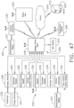
- the evacuation systems disclosed herein can be incorporated into a computer-implemented interactive surgical system, such as the system 100 ( FIG. 39 ) or the system 200 ( FIG. 47 ), for example.
- the computer-implemented surgical system 100 can include at least one hub 106 and a cloud 104.
- the hub 106 includes a smoke evacuation module 126. Operation of the smoke evacuation module 126 can be controlled by the hub 106 based on its situational awareness and/or feedback from the components thereof and/or based on information from the cloud 104.
- the computer-implemented surgical systems 100 and 200, as well as situational awareness therefor, are further described herein.
- Situational awareness encompasses the ability of some aspects of a surgical system to determine or infer information related to a surgical procedure from data received from databases and/or instruments.
- the information can include the type of procedure being undertaken, the type of tissue being operated on, or the body cavity that is the subject of the procedure.
- the surgical system can, for example, improve the manner in which it controls the modular devices (e.g. a smoke evacuation system) that are connected to it and provide contextualized information or suggestions to the clinician during the course of the surgical procedure.
- Situational awareness is further described herein and in U.S. Provisional Patent Application Serial No. 62/611,341, entitled INTERACTIVE SURGICAL PLATFORM, filed December 28, 2017 ,
- FIG. 5 is a schematic representation of an electrosurgical system 50300 including a processor 50308.
- the electrosurgical system 50300 is powered by an AC source 50302, which provides either 120 V or 240 V alternating current.
- the voltage supplied by the AC source 50302 is directed to an AC/DC converter 50304, which converts the 120 V or 240 V of alternating current to 360 V of direct current.
- the 360 V of direct current is then directed to a power converter 50306 (e.g., a buck converter).
- the power converter 50306 is a step-down DC to DC converter.
- the power converter 50306 is adapted to step-down the incoming 360 V to a desired level within a range between 0-150 V.
- the processor 50308 can be programmed to regulate various aspects, functions, and parameters of the electrosurgical system 50300. For instance, the processor 50308 can determine the desired output power level at an electrode tip 50334, which can be similar in many respects to the electrode tip 50034 in FIG. 2 and/or the electrode tip 51034 in FIG. 3 , for example, and direct the power converter 50306 to step-down the voltage to a specified level so as to provide the desired output power.
- the processor 50308 is coupled to a memory 50310 configured to store machine executable instructions to operate the electrosurgical system 50300 and/or subsystems thereof.
- DAC digital-to-analog converter
- the DAC 50312 is adapted to convert a digital code created by the processor 50308 to an analog signal (current, voltage, or electric charge) which governs the voltage step-down performed by the power converter 50306.
- the power converter 50306 steps-down the 360 V to a level that the processor 50308 has determined will provide the desired output power level, the stepped-down voltage is directed to the electrode tip 50334 to effectuate electrosurgical treatment of a patient's tissue and is then directed to a return or ground electrode 50335.
- a voltage sensor 50314 and a current sensor 50316 are adapted to detect the voltage and current present in the electrosurgical circuit and communicate the detected parameters to the processor 50308 so that the processor 50308 can determine whether to adjust the output power level.
- typical wave generators are adapted to maintain the selected settings throughout an electrosurgical procedure.
- the operational parameters of a generator can be optimized during a surgical procedure based on one or more inputs to the processor 5308, such as inputs from a surgical hub, cloud, and/or situational awareness module, for example, as further described herein.
- the processor 50308 is coupled to a communication device 50318 to communicate over a network.
- the communication device includes a transceiver 50320 configured to communicate over physical wires or wirelessly.
- the communication device 50318 may further include one or more additional transceivers.
- the transceivers may include, but are not limited to cellular modems, wireless mesh network transceivers, Wi-Fi ® transceivers, low power wide area (LPWA) transceivers, and/or near field communications transceivers (NFC).
- the communication device 50318 may include or may be configured to communicate with a mobile telephone, a sensor system (e.g., environmental, position, motion, etc.) and/or a sensor network (wired and/or wireless), a computing system (e.g., a server, a workstation computer, a desktop computer, a laptop computer, a tablet computer (e.g., iPad ® , GalaxyTab ® and the like), an ultraportable computer, an ultramobile computer, a netbook computer and/or a subnotebook computer; etc.
- a coordinator node e.g., a coordinator node.
- the transceivers 50320 may be configured to receive serial transmit data via respective UARTs from the processor 50308, to modulate the serial transmit data onto an RF carrier to produce a transmit RF signal and to transmit the transmit RF signal via respective antennas.
- the transceiver(s) are further configured to receive a receive RF signal via respective antennas that includes an RF carrier modulated with serial receive data, to demodulate the receive RF signal to extract the serial receive data and to provide the serial receive data to respective UARTs for provision to the processor.
- Each RF signal has an associated carrier frequency and an associated channel bandwidth. The channel bandwidth is associated with the carrier frequency, the transmit data and/or the receive data.
- Each RF carrier frequency and channel bandwidth are related to the operating frequency range(s) of the transceiver(s) 50320.
- Each channel bandwidth is further related to the wireless communication standard and/or protocol with which the transceiver(s) 50320 may comply.
- each transceiver 50320 may correspond to an implementation of a selected wireless communication standard and/or protocol, e.g., IEEE 802.11 a/b/g/n for Wi-Fi ® and/or IEEE 802.15.4 for wireless mesh networks using Zigbee routing.
- the processor 50308 is coupled to a sensing and intelligent controls device 50324 that is coupled to a smoke evacuator 50326.
- the smoke evacuator 50326 can include one or more sensors 50327, and can also include a pump and a pump motor controlled by a motor driver 50328.
- the motor driver 50328 is communicatively coupled to the processor 50308 and a pump motor in the smoke evacuator 50326.
- the sensing and intelligent controls device 50324 includes sensor algorithms 50321 and communication algorithms 50322 that facilitate communication between the smoke evacuator 50326 and other devices to adapt their control programs.
- the sensing and intelligent controls device 50324 is configured to evaluate extracted fluids, particulates, and gases via an evacuation conduit 50336 to improve smoke extraction efficiency and/or reduce device smoke output, for example, as further described herein.
- the sensing and intelligent controls device 50324 is communicatively coupled to one or more sensors 50327 in the smoke evacuator 50326, one or more internal sensors 50330 and/or one or more external sensors 50332 of the electrosurgical system 50300.
- a processor can be located within an evacuator housing of a surgical evacuation system.
- a processor 50408 and a memory 50410 therefor are positioned within an evacuator housing 50440 of a surgical evacuation system 50400.
- the processor 50408 is in signal communication with a motor driver 50428, various internal sensors 50430, a display 50442, the memory 50410, and a communication device 50418.
- the communication device 50418 is similar in many respects to the communication device 50318 described above with respect to FIG. 5 .
- the communication device 50418 can allow the processor 50408 in the surgical evacuation system 50400 to communicate with other devices within a surgical system.
- the communication device 50418 can allow wired and/or wireless communication to one or more external sensors 50432, one or more surgical devices 50444, one or more hubs 50448, one or more clouds 50446, and/or one or more additional surgical systems and/or tools.
- the surgical evacuation system 50400 of FIG. 6 can be incorporated into the electrosurgical system 50300 of FIG. 5 in certain instances.
- the surgical evacuation system 50400 also includes a pump 50450, including a pump motor 50451 thereof, an evacuation conduit 50436, and an exhaust 50452.
- Various pumps, evacuation conduits and exhausts are further described herein.
- the surgical evacuation system 50400 can also include a sensing and intelligent controls device, which can be similar in many respects to the sensing and intelligent controls device 50324, for example.
- a sensing and intelligent controls device can be in signal communication with the processor 50408 and/or one or more of the sensors 50430 and/or external sensors 50432.
- a processor and sensor system such as the processors 50308 and 50408 and respective sensor systems in communication therewith ( FIGS. 5 and 6 ), are configured to sense the airflow through a vacuum source in order to adjust parameters of the smoke evacuation system and/or external devices and/or systems that are used in tandem with the smoke evacuation system, such as an electrosurgical system, energy device, and/or generator, for example.
- the sensor system may include multiple sensors positioned along the airflow path of the surgical evacuation system. The sensors can measure a pressure differential within the evacuation system, in order to detect a state or status of the system between the sensors.
- the system between two sensors can be a filter, and the pressure differential can be used to increase the speed of the pump motor as flow through the filter is reduced, in order to maintain a flow rate through the system.
- the system can be a fluid trap of the evacuation system, and the pressure differential can be used to determine an airflow path through the evacuation system.
- the system can be the inlet and outlet (or exhaust) of the evacuation system, and the pressure differential can be used to determine the maximum suction load in the evacuation system in order to maintain the maximum suction load below a threshold value.
- a processor and sensor system such as the processors 50308 and 50408 and respective sensor systems in communication therewith ( FIGS. 5 and 6 ), are configured to detect the ratio of an aerosol or carbonized particulate, i.e. smoke, in the fluid extracted from a surgical site.
- the sensing system may include a sensor that detects the size and/or the composition of particles, which is used to select an airflow path through the evacuation system.
- the evacuation system can include a first filtering path, or first filtering state, and a second filtering path, or second filtering state, which can have different properties.
- the first path includes only a particulate filter
- the second path includes both a fluid filter and the particulate filter.
- the first path includes a particulate filter
- the second path includes the particulate filter and a finer particulate filter arranged in series. Additional and/or alternative filtering paths are also envisioned.
- a processor and sensor system such as the processors 50308 and 50408 and respective sensor systems in communication therewith ( FIGS. 5 and 6 ), are configured to perform a chemical analysis on the particles evacuated from within the abdomen cavity of a patient.
- the sensing and intelligent controls device 50324 may sense the particle count and type in order to adjust the power level of the ultrasonic generator in order to induce the ultrasonic blade to produce less smoke.
- the sensor systems may include sensors for detecting the particle count, the temperature, the fluid content, and/or the contamination percentage of the evacuated fluid, and can communicate the detected property or properties to a generator in order to adjust its output.
- the smoke evacuator 50326 and/or the sensing and intelligent controls device 50324 therefor can be configured to adjust the evacuation flow rate and/or the pump's motor speed and, at a predefined particulate level, may operably affect the output power or waveform of the generator to lower the smoke generated by the end effector.
- a processor and sensor system such as the processors 50308 and 50408 and respective sensor systems therewith ( FIGS. 5 and 6 ), are configured to evaluate particle count and contamination in the operating room by evaluating one or more properties in the ambient air and/or the exhaust from the evacuator housing.
- the particle count and/or the air quality can be displayed on the smoke evacuation system, such as on the evacuator housing, for example, in order to communicate the information to a clinician and/or to establish the effectiveness of the smoke evacuation system and filter(s) thereof.
- a processor such as the processor 50308 or the processor 50408 ( FIGS. 5 and 6 ), for example, is configured to compare a sample rate image obtained from an endoscope to the evacuator particle count from the sensing system (e.g. the sensing and intelligent controls device 50324) in order to determine a correlation and/or to adjust the rate of the pump's revolutions-per-minute (RPM).
- the activation of the generator can be communicated to the smoke evacuator such that an anticipated, required rate of smoke evacuation can be implemented.
- the generator activation can be communicated to the surgical evacuation system through a surgical hub, cloud communication system, and/or direct connection, for example.
- sensor systems and algorithms for a smoke evacuation system can be configured to control the smoke evacuator, and can adapt motor parameters thereof to adjust the filtering efficiency of the smoke evacuator based on the needs of the surgical field at a given time.
- an adaptive airflow pump speed algorithm is provided to automatically change the motor pump speed based on the sensed particulate into the inlet of the smoke evacuator and/or out of the outlet or exhaust of the smoke evacuator.
- the sensing and intelligent controls device 50324 FIG. 5
- the airflow through the evacuation system can be scalable based on the smoke into the evacuation system and/or a lack of filtered particles out of the smoke evacuation system.
- the auto-mode speed can provide automatic sensing and compensation for laparoscopic mode in certain instances.
- the evacuation system can include an electrical and communication architecture (see, e.g. FIGS. 5 and 6 ) that provides data collection and communication features, in order to improve interactivity with a surgical hub and a cloud.
- a surgical evacuation system and/or processor therefor such as the processor 50308 ( FIG. 5 ) and the processor 50408 ( FIG. 6 ), for example, can include a segmented control circuit that is energized in a staged method to check for errors, shorts, and/or safety checks of the system.
- the segmented control circuit may also be configured to have a portion energized and a portion not energized until the energized portion performs a first function.
- the segmented control circuit can include circuit elements to identify and display status updates to the user of attached components.
- the segmented control circuit also includes circuit elements for running the motor in a first state, in which the motor is activated by the user, and in a second state, in which the motor has not been activated by the user but runs the pump in a quieter manner and at a slower rate.
- a segmented control circuit can allow the smoke evacuator to be energized in stages, for example.
- the electrical and communication architecture for the evacuation system can also provide interconnectivity of the smoke evacuator with other components within the surgical hub for interactions, as well as communication of data with a cloud.
- Communication of surgical evacuation system parameters to a surgical hub and/or cloud can be provided to affect the output or operation of other attached devices.
- the parameters can be operational or sensed. Operational parameters include airflow, pressure differentials, and air quality. Sensed parameters include particulate concentration, aerosol percentage, and chemical analysis.
- the evacuation system such as the surgical evacuation system 50400, for example, can also include an enclosure and replaceable components, controls, and a display. Circuit elements are provided for communicating the security identification (ID) between such replaceable components. For example, communication between a filter and the smoke evacuation electronics can be provided to verify authenticity, remaining life of the component, to update parameters in the component, to log errors, and/or to limit the number and/or the type of components that can be identified by the system.
- the communication circuit can authenticate features for enabling and/or disabling of configuration parameters.
- the communication circuit can employ encryption and/or error handling schemes to manage security and proprietary relationships between the component and the smoke evacuation electronics. Disposable/re-useable components are included in certain instances.
- the evacuation systems can provide fluid management and extraction filters and airflow configurations.
- a surgical evacuation system including a fluid capture mechanism is provided where the fluid capture mechanism has a first and a second set of extraction or airflow control features, which are in series with each other to extract large and small fluid droplets, respectively.
- the airflow path can contain a recirculation channel or secondary fluid channel back to the primary reservoir from downstream of the exhaust port of the main fluid management chamber.
- An electrosurgical system can includes a signal generator, an electrosurgical instrument, a return electrode, and a surgical evacuation system.
- the generator may be an RF wave generator that produces RF electrical energy.
- Connected to the electrosurgical instrument is a utility conduit.
- the utility conduit includes a cable that communicates electrical energy from the signal generator to the electrosurgical instrument.
- the utility conduit also includes a vacuum hose that conveys captured/collected smoke and/or fluid away from a surgical site.
- FIG. 7 Such an exemplary electrosurgical system 50601 is shown in FIG. 7 . More specifically, the electrosurgical system 50601 includes a generator 50640, an electrosurgical instrument 50630, a return electrode 50646, and an evacuation system 50600.
- the electrosurgical instrument 50630 includes a handle 50632 and a distal conduit opening 50634 that is fluidically coupled to a suction hose 50636 of the evacuation system 50600.
- the electrosurgical instrument 50630 also includes an electrode that is powered by the generator 50640.
- a first electrical connection 50642, e.g., a wire extends from the electrosurgical instrument 50630 to the generator 50640.
- a second electrical connection 50644, e.g., a wire extends from the electrosurgical instrument 50630 to electrode, i.e., the return electrode 50646.
- the electrosurgical instrument 50630 can be a bipolar electrosurgical instrument.
- the distal conduit opening 50634 on the electrosurgical instrument 50630 is fluidically coupled to the suction hose 50636 that extends to a filter end cap 50603 of a filter that is installed in an evacuator housing 50618 of the evacuation system 50600.
- the electrosurgical instrument 50630 is configured to deliver electrical energy to target tissue of a patient to cut the tissue and/or cauterize blood vessels within and/or near the target tissue, as described herein. Specifically, an electrical discharge is provided by the electrode tip to the patient in order to cause heating of cellular matter of the patient that is in close contact with or adjacent to electrode tip. The tissue heating takes place at an appropriately high temperature to allow the electrosurgical instrument 50630 to be used to perform electrosurgery.
- the return electrode 50646 is either applied to or placed in close proximity to the patient (depending on the type of return electrode), in order to complete the circuit and provide a return electrical path to the generator 50640 for energy that passes into the patient's body.
- the evacuation conduit opening 50634 is near the electrode tip, the evacuation system 50600 is configured to capture the smoke that is released during a surgical procedure. Vacuum suction may draw the smoke into the conduit opening 50634, through the electrosurgical instrument 50630, and into the suction hose 50636 toward the evacuator housing 50618 of the evacuation system 50600.
- the evacuator housing 50618 of the evacuation system 50600 ( FIG. 7 ) is depicted.
- the evacuator housing 50618 includes a socket 50620 that is dimensioned and structured to receive a filter.
- the evacuator housing 50618 can completely or partially encompass the internal components of the evacuator housing 50618.
- the socket 50620 includes a first receptacle 50622 and a second receptacle 50624.
- a transition surface 50626 extends between the first receptacle 50622 and the second receptacle 50624.
- Surgical evacuation systems often use filters to remove unwanted pollutants from the smoke before the smoke is released as exhaust.
- the filters can be replaceable.
- the reader will appreciate that the filter 50670 depicted in FIGS. 10 and 11 can be employed in various evacuation systems disclosed herein.
- the filter 50670 can be a replaceable and/or disposable filter.
- the filter 50670 includes a front cap 50672, a back cap 50674, and a filter body 50676 disposed therebetween.
- the front cap 50672 includes a filter inlet 50678, which, in certain instances, is configured to receive smoke directly from the suction hose 50636 ( FIG. 7 ) or other smoke source.
- the front cap 50672 can be replaced by a fluid trap (e.g. the fluid trap 50760 depicted in FIGS. 14-17 ) that directs the smoke directly from the smoke source, and after removing at least a portion of the fluid therefrom, passes the partially processed smoke into the filter body 50676 for further processing.
- the filter inlet 50678 can be configured to receive smoke via a fluid trap exhaust port, such as a port 50766 in a fluid trap 50760 ( FIGS. 14-17 ) to communicate partially processed smoke into the filter 50670.
- the ULPA filtration utilizes a depth filter that is similar to a maze.
- the particulate can be filtered using at least one of the following methods: direct interception (in which particles over 1.0 micron are captured because they are too large to pass through the fibers of the media filter), inertial impaction (in which particles between 0.5 and 1.0 micron collide with the fibers and remain there, and diffusional interception (in which particles less than 0.5 micron are captured by the effect of Brownian random thermal motion as the particles "search out” fibers and adhere to them).
- the filter 50670 includes a coarse media filter layer 50684 followed by a fine particulate filter layer 50686.
- the filter 50670 may consist of a single type of filter.
- the filter 50670 can include more than two filter layers and/or more than two different types of filter layers.
- the smoke is drawn through a carbon reservoir 50688 in the filter 50670 to remove gaseous contaminants within the smoke, such as volatile organic compounds, for example.
- the carbon reservoir 50688 can comprise a charcoal filter.
- the filtered smoke which is now substantially free of particulate matter and gaseous contaminants, is drawn through the filter exhaust 50680 and into the evacuation system 50600 for further processing and/or elimination.
- the filter 50670 includes a plurality of dams between components of the filter body 50676.
- a first dam 50690 is positioned intermediate the filter inlet 50678 ( FIG. 10 ) and a first particulate filter, such as the coarse media filter 50684, for example.
- a second dam 50692 is positioned intermediate a second particulate filter, such as the fine particulate filter 50686, for example, and the carbon reservoir 50688.
- a third dam 50694 is positioned intermediate the carbon reservoir 50688 and the filter exhaust 50680.
- the dams 50690, 50692, and 50694 can comprise a gasket or O-ring, which is configured to prevent movement of the components within the filter body 50676.
- the size and shape of the dams 50690, 50692, and 50694 can be selected to prevent distention of the filter components in the direction of the applied suction.
- the coarse media filter 50684 can include a low-air-resistant filter material, such as fiberglass, polyester, and/or pleated filters that are configured to remove a majority of particulate matter larger than 10 ⁇ m, for example.
- this includes filters that remove at least 85% of particulate matter larger than 10 ⁇ m, greater than 90% of particulate matter larger than 10 ⁇ m, greater than 95% of particular matter larger than 10 ⁇ m, greater than 99% of particular matter larger than 10 ⁇ m, greater than 99.9% particulate matter larger than 10 ⁇ m, or greater than 99.99% particulate matter larger than 10 ⁇ m.
- the fine particulate filter 50686 can include any filter of higher efficiency than the coarse media filter 50684. This includes, for example, filters that are capable of filtering a higher percentage of the same sized particles as the coarse media filter 50684 and/or capable of filtering smaller sized particles than the coarse media filter 50684.
- the fine particulate filter 50686 can include a HEPA filter or an ULPA filter. Additionally or alternatively, the fine particulate filter 50686 can be pleated to increase the surface area thereof.
- the coarse media filter 50684 includes a pleated HEPA filter and the fine particulate filter 50686 includes a pleated ULPA filter.
- the carbon reservoir 50688 is bounded by porous dividers 50696 and 50698 disposed between the intermediate and terminal dams 50692 and 50694, respectively.
- the porous dividers 50696 and 50698 are rigid and/or inflexible and define a constant spatial volume for the carbon reservoir 50688.
- the evacuation system 50500 includes the pump 50506 within the evacuator housing 50518.
- the evacuation system 50600 depicted in FIG. 7 can include a pump located in the evacuator housing 50618, which can generate suction to pull smoke from the surgical site, through the suction hose 50636 and through the filter 50670 ( FIGS. 10 and 11 ).
- the pump can create a pressure differential within the evacuator housing 50618 that causes the smoke to travel into the filter 50670 and out an exhaust mechanism (e.g. exhaust mechanism 50520 in FIG. 4 ) at the outlet of the flow path.
- the filter 50670 is configured to extract harmful, foul, or otherwise unwanted particulates from the smoke.
- the pump can be disposed in-line with the flow path through the evacuator housing 50618 such that the gas flowing through the evacuator housing 50618 enters the pump at one end and exits the pump at the other end.
- the pump can provide a sealed positive displacement flow path.
- the pump can produce the sealed positive displacement flow path by trapping (sealing) a first volume of gas and decreasing that volume to a second smaller volume as the gas moves through the pump. Decreasing the volume of the trapped gas increases the pressure of the gas.
- the second pressurized volume of gas can be released from the pump at a pump outlet.
- the pump can be a compressor.
- the pump can comprise a hybrid regenerative blower, a claw pump, a lobe compressor, and/or a scroll compressor.
- Positive displacement compressors can provide improved compression ratios and operating pressures while limiting vibration and noise generated by the evacuation system 50600.
- the evacuation system 50600 can include a fan for moving fluid therethrough.
- FIG. 12 An example of a positive displacement compressor, e.g. a scroll compressor pump 50650, is depicted in FIG. 12 .
- the scroll compressor pump 50650 includes a stator scroll 50652 and a moving scroll 50654.
- the stator scroll 50652 can be fixed in position while the moving scroll 50654 orbits eccentrically.
- the moving scroll 50654 can orbit eccentrically such that it rotates about the central longitudinal axis of the stator scroll 50652.
- the central longitudinal axes of the stator scroll 50652 and the moving scroll 50654 extend perpendicular to the viewing plane of the scrolls 50652, 50654.
- the stator scroll 50652 and the moving scroll 50654 are interleaved with each other to form discrete sealed compression chambers 50656.
- the evacuation system 50700 can be similar in many respects to the evacuation system 50600 ( FIG. 7 ).
- the evacuation system 50700 includes the evacuator housing 50618 and the suction hose 50636.
- the evacuation system 50600 is configured to produce suction and thereby draw smoke from the distal end of the suction hose 50636 into the evacuator housing 50618 for processing.
- the suction hose 50636 is not connected to the evacuator housing 50618 through the filter end cap 50603 in FIG. 13 .
- suction hose 50636 is connected to the evacuator housing 50618 through the fluid trap 50760.
- a filter similar to the filter 50670 can be positioned within the socket of the evacuator housing 50618 behind the fluid trap 50760.
- the fluid trap 50760 is a first processing point that extracts and retains at least a portion of the fluid (e.g. liquid) from the smoke before relaying the partially-processed smoke to the evacuation system 50700 for further processing and filtration.
- the evacuation system 50700 is configured to process, filter, and otherwise clean the smoke to reduce or eliminate unpleasant odors or other problems associated with smoke generation in the surgical theater (or other operating environment), as described herein.
- the fluid trap 50760 can, among other things, increase the efficiency of the evacuation system 50700 and/or increase the life of filters associated therewith, in certain instances.
- other mechanisms for coupling or joining the suction hose 50636 to the inlet port 50762 can be employed such as a latch-based compression fitting, an O-ring, threadably coupling the suction hose 50636 with the inlet port 50762, for example, and/or other coupling mechanisms.
- a fluid tight and/or airtight fit between the suction hose 50636 and the fluid trap 50760 is configured to prevent fluids and/or other materials in the evacuated smoke from leaking at or near the junction of these components.
- the suction hose 50636 can be associated with the inlet port 50762 through an intermediate coupling device, such as an O-ring and/or adaptor, for example, to further ensure an airtight and/or fluid tight connection between the suction hose 50636 and the fluid trap 50760.
- the fluid trap 50760 includes the exhaust port 50766.
- the exhaust port extends away from a rear cover or surface 50768 of the fluid trap 50760.
- the exhaust port 50766 defines an open channel between an interior chamber 50770 of the fluid trap 50760 and the exterior environment.
- the exhaust port 50766 is sized and shaped to tightly associate with a surgical evacuation system or components thereof.
- the exhaust port 50766 can be sized and shaped to associate with and communicate at least partially processed smoke from the fluid trap 50760 to a filter housed within an evacuator housing 50618 ( FIG. 13 ).
- the exhaust port 50766 can extend away from the front plate, a top surface, or a side surface of the fluid trap 50760.
- the exhaust port 50766 includes a membrane, which spaces the exhaust port 50766 apart from the evacuator housing 50618.
- a membrane can act to prevent water or other liquid collected in the fluid trap 50760 from being passed through the exhaust port 50766 and into the evacuator housing 50618 while permitting air, water and/or vapor to freely pass into the evacuator housing 50618.
- a high flow rate microporous polytetrafluoroethylene (PTFE) can be positioned downstream of the exhaust port 50766 and upstream of a pump to protect the pump or other components of the evacuation system 50700 from damage and/or contamination.
- the fluid trap 50760 also includes a gripping region 50772, which is positioned and dimensioned to assist a user in handling the fluid trap 50760 and/or connecting the fluid trap 50760 with the suction hose 50636 and/or the evacuator housing 50618.
- the gripping region 50772 is depicted as being an elongate recess; however, the reader will readily appreciate that the gripping region 50772 may include at least one recess, groove, protrusion, tassel, and/or ring, for example, which can be sized and shaped to accommodate a user's digits or to otherwise provide a gripping surface.
- the interior chamber 50770 of the fluid trap 50760 is depicted.
- the relative positioning of the inlet port 50762 and the exhaust port 50766 is configured to promote the extraction and the retention of fluid from the smoke as it passes into the fluid trap 50760.
- the inlet port 50762 can comprise a notched cylindrical shape, which can direct the smoke and the accompanying fluid towards a fluid reservoir 50774 of the fluid trap 50760 or otherwise directionally away from the exhaust port 50766.
- An example of such a fluid flow is depicted with arrows A, B, C, D, and E in FIG. 17 .
- the smoke entering the inlet port 50762 is initially directed primarily downward into the fluid reservoir 50774 of the fluid trap 50760 (illustrated by the arrows B).
- the directional flow of smoke through the fluid trap 50760 can ensure that liquids within the smoke are extracted and retained within the lower portion (e.g. the fluid reservoir 50774) of the fluid trap 50760. Furthermore, the relative positioning of the exhaust port 50766 vertically above the inlet port 50762 when the fluid trap 50760 is in an upright position is configured to discourage liquid from inadvertently being carried through the exhaust port 50766 by the flow of smoke while not substantially hindering fluid flow into and out of the fluid trap 50760. Additionally, in certain instances, the configuration of the inlet port 50762 and the outlet port 50766 and/or the size and shape of the fluid trap 50760 itself, can enable the fluid trap 50760 to be spill resistant.
- an evacuation system can include a plurality of sensors and intelligent controls, as further described herein with respect to FIGS. 5 and 6 , for example.
- an evacuation system can include one or more temperatures sensors, one or more fluid detection sensors, one or more pressure sensors, one or more particle sensors, and/or one or more chemical sensors.
- a temperature sensor can be positioned to detect the temperature of a fluid at the surgical site, moving through a surgical evacuation system, and/or being exhaust into a surgical theater from a surgical evacuation system.
- a pressure sensor can be positioned to detect a pressure within the evacuation system, such as within the evacuator housing.
- a pressure sensor can be positioned upstream of the filter, between the filter and the pump, and/or downstream of the pump.
- FIG. 18 An evacuator housing 50818 for an evacuation system 50800 is schematically depicted in FIG. 18 .
- the evacuator housing 50818 can be similar in many respects to the evacuator housings 50018 and/or 50618, for example, and/or can be incorporated into various evacuation systems disclosed herein.
- the evacuator housing 50818 includes numerous sensors, which are further described herein. The reader will appreciate that certain evacuator housings may not include each sensor depicted in FIG. 18 and/or may include additional sensor(s). Similar to the evacuator housings 50018 and 50618 disclosed herein, the evacuator housing 50818 of FIG. 18 includes an inlet 50822 and an outlet 50824. A fluid trap 50860, a filter 50870, and a pump 50806 are sequentially aligned along a flow path 50804 through the evacuator housing 50818 between the inlet 50822 and the outlet 50824.
- An evacuator housing can include modular and/or replaceable components, as further described herein.
- an evacuator housing can include a socket or a receptacle 50871 dimensioned to receive a modular fluid trap and/or a replaceable filter.
- a fluid trap and a filter can be incorporated into a single interchangeable module 50859, as depicted in FIG. 18 .
- the fluid trap 50860 and the filter 50870 form the interchangeable module 50859, which can be modular and/or replaceable, and can be removably installed in the receptacle 50871 in the evacuator housing 50818.
- the fluid trap 50860 and the filter 50870 can be separate and distinct modular components, which can be assembled together and/or separately installed in the evacuator housing 50818.
- the evacuator housing 50818 includes a plurality of sensors for detecting various parameters therein and/or parameters of the ambient environment. Additionally or alternatively, one or more modular components installed in the evacuator housing 50818 can include one or more sensors.
- the interchangeable module 50859 includes a plurality of sensors for detecting various parameters therein.
- the evacuator housing 50818 and/or a modular component(s) compatible with the evacuator housing 50818 can include a processor, such as the processor 50308 and 50408 ( FIGS. 5 and 6 , respectively), which is configured to receive inputs from one or more sensors and/or to communicate outputs to one more systems and/or drivers.
- a processor such as the processor 50308 and 50408 ( FIGS. 5 and 6 , respectively)
- smoke from a surgical site can be drawn into the inlet 50822 to the evacuator housing 50818 via the fluid trap 50860.
- the flow path 50804 through the evacuator housing 50818 in FIG. 18 can comprise a sealed conduit or tube 50805 extending between the various in-line components.
- the smoke can flow past a fluid detection sensor 50830 and a chemical sensor 50832 to a diverter valve 50834, which is further described herein.
- a fluid detection sensor such as the sensor 50830, can detect fluid particles in the smoke.
- the fluid detection sensor 50830 can be a continuity sensor.
- the fluid detection sensor 50830 can include two spaced-apart electrodes and a sensor for detecting the degree of continuity therebetween. When no fluid is present, the continuity can be zero, or substantially zero, for example.
- the chemical sensor 50832 can detect the chemical properties of the smoke.
- fluid can be directed into a condenser 50835 of the fluid trap 50860 and the smoke can continue toward the filter 50870.
- Baffles 50864 are positioned within the condenser 50835 to facilitate the condensation of fluid droplets from the smoke into a reservoir in the fluid trap 50860.
- a fluid detection sensor 50836 can ensure any fluid in the evacuator housing is entirely, or at least substantially, captured within the fluid trap 50860.
- the filtered smoke can flow past a pressure sensor 50846 and can then continue along the flow path 50804 within the evacuator housing 50818 toward the pump 50806.
- the filtered smoke can flow past a particle sensor 50848 and a pressure sensor 50850 at the outlet to the evacuator housing 50818.
- the particle sensor 50848 can comprise a laser particle counter, as further described herein.
- the evacuator housing 50818 in FIG. 18 also includes an air quality particle sensor 50852 and an ambient pressure sensor 50854 to detect various properties of the ambient environment, such as the environment within the surgical theater.
- the air quality particle sensor, or external/ambient air particle sensor, 50852 can comprise a laser particle counter in at least one form.
- the various sensors depicted in FIG. 18 are further described herein.
- alternative sensing means can be utilized in the smoke evacuation systems disclosed herein.
- alternative sensors for counting particles and/or determining particulate concentration in a fluid are further disclosed herein.
- the filter 50870 can include additional and/or fewer filtering levels.
- the filter 50870 can include one or more filtering layers selected from the following group of filters: a course media filter, a fine media filter, and a sorbent-based filter.
- the course media filter can be a low-air-resistant filter, which can be comprised of fiberglass, polyester, and/or pleated filters, for example.
- the fine media filter can be a high efficiency particulate air (HEPA) filter and/or ULPA filter.
- the sorbent-based filter can be an activated-carbon filter, for example.
- the pump 50806 depicted in FIG. 18 can be replaced by and/or used in combination with another compressor and/or pump, such as a hybrid regenerative blower, a claw pump, and/or a lobe compressor, for example.
- a hybrid regenerative blower such as a hybrid regenerative blower, a claw pump, and/or a lobe compressor, for example.
- a lobe compressor such as a hybrid regenerative blower, a claw pump, and/or a lobe compressor, for example.
- various alternative pumping arrangements and geometries can be employed to generate suction within the flow path 50804 to draw smoke into the evacuator housing 50818.
- FIG. 19 another evacuator housing 50918 for an evacuation system 50900 is depicted.
- the evacuator housing 50918 in FIG. 19 can be similar in many respects to the evacuator housing 50818 in FIG. 18 .
- the evacuator housing 50918 defines a flow path 50904 between an inlet 50922 to the evacuator housing 50918 and an outlet 50924 to the evacuator housing 50918.
- a fluid trap 50960, a filter 50970, and a pump 50906 are sequentially arranged.
- the evacuator housing 50918 also includes a centrifugal blower arrangement 50980 and a recirculating valve 50990.
- the recirculating valve 50990 can selectively open and close to recirculate fluid through the fluid trap 50960. For example, if the fluid detection sensor 50836 detects a fluid, the recirculating valve 50990 can be opened such that the fluid is directed back away from the filter 50970 and back into the fluid trap 50960. If the fluid detection sensor 50836 does not detect a fluid, the valve 50990 can be closed such that the smoke is directed into the filter 50970. When fluid is recirculated via the recirculating valve 50990, the fluid can be drawn through a recirculation conduit 50982.
- the centrifugal blower arrangement 50980 is engaged with the recirculation conduit 50982 to generate a recirculating suction force in the recirculation conduit 50982. More specifically, when the recirculating valve 50990 is open and the pump 50906 is activated, the suction force generated by the pump 50906 downstream of the filter 50970 can generate rotation of the first centrifugal blower, or squirrel cage, 50984, which can be transferred to the second centrifugal blower, or squirrel cage, 50986, which draws the recirculated fluid through the recirculating valve 50990 and into the fluid trap 50960.
- control schematics of FIGS. 5 and 6 can be utilized with the various sensor systems and evacuator housings of FIGS. 18 and 19 .
- Smoke evacuated from a surgical site can include liquids, aerosols, and/or gases, and/or can include material of different chemical and/or physical properties, such as particulate matter and particles of different sizes and/or densities, for example.
- the different types of materials evacuated from a surgical site can affect the efficiency of the surgical evacuation system and the pump thereof. Moreover, certain types of material can require the pump to draw excessive power and/or can risk damaging the motor for the pump.
- the power supplied to the pump can be modulated to control the flowrate of smoke through the evacuation system based on input from one or more sensors along the flow path.
- Output from the sensors can be indicative of a state or quality of the smoke evacuation system and/or one or more properties of the evacuated smoke such as the type(s) and ratios of matter, chemical properties, density, and/or size of particulates, for example.
- a pressure differential between two pressure sensors in the evacuation system can indicate the state of the region therebetween such as the state of a filter, a fluid trap, and/or the overall system, for example.
- an operational parameter of the motor for the pump can be adjusted by changing the current supplied to the motor and/or the duty cycle, which is configured to change the motor speed.
- the efficiency of the filter can be improved and/or the motor can be protected from burnout.
- a surgical evacuation system can include one or more particle counters, or particle sensors, for detecting the size and/or concentration of particulate within the smoke.
- particle sensors 50838 and 50848 are depicted.
- a particle sensor can be an optical sensor, a laser sensor, a photoelectric sensor, an ionization sensor, an electrostatic sensor, and/or combinations thereof.
- Various particle sensors are further described herein.
- the speed of the motor and, thus, the speed of the pump can be adjusted based on the particulate concentration detected by the one or more particle sensors in a surgical evacuation system. For example, when the particle sensor(s) detects an increased concentration of particulate in the flow path, which can correspond to an increased quantity of smoke in the flow path, the speed of the motor can be increased to increase the speed of the pump and to draw more fluid into the smoke evacuation system from the surgical site. Similarly, when the particle sensor(s) detects a decreased concentration of particulate in the flow path, which can correspond to a decreased quantity of smoke in the flow path, the speed of the motor can be decreased to decrease the speed of the pump and to reduce suction from the surgical site. Additional and alternative adjustment algorithms for the surgical evacuation system are further described herein. Moreover, in certain instances, based on the sensor data from the smoke evacuation system, a generator in the surgical system can be controlled to adjust the amount of smoke generated at the surgical site, as further described herein.
- the system can include one or more sensors for detecting the particulate concentration in the ambient room, for example, in the operating room or surgical theater.
- the air quality particle sensor 50852 is installed on an external surface of the evacuator housing 50818. Alternative locations for the air quality particle sensor 50852 are also envisioned.
- a particle sensor can be positioned downstream of the filter and, in certain instances, can be positioned at or near the outlet of the filter.
- the particle sensor 50848 is positioned downstream of the filter 50870 and the pump 50806 in the smoke evacuation system 50800 and is positioned downstream of the filter 50970 and the pump 50906 in the smoke evacuation system 50900. Because the particle sensor 50848 is positioned downstream of the filter(s) 50870, 50970, the particle sensor is configured to confirm that the filter(s) 50870, 50970 have removed sufficient particulate from the smoke.
- such a sensor can be adjacent to the exhaust outlet 50824, 50924 of the evacuator housing 50818, 50918, respectively.
- an electrostatic particle sensor can be utilized.
- the exhaust outlet 50824, 50924 can include an electrostatic particulate sensor that the exhaust flows past downstream of the filtration system and prior to being exhaust into the surgical theater.
- the particulate concentration detected by one or more sensors of the surgical evacuation system can be communicated to a clinician in a number of different ways.
- the evacuator housing 50818, 50918 and/or the evacuation device e.g. the electrosurgical instrument 50032 in FIG. 2
- the evacuation device can include an indicator, such as one or more lights and/or display screens.
- an LED on the evacuator housing 50818, 50819 may change color (e.g. from blue to red) depending on the volume of particulate detected by the sensor(s).
- the indicator can include an alarm or warning, which can be tactile, auditory, and/or visual, for example.
- the clinician(s) in the surgical theater can be notified by the indicator(s).
- a surgical evacuation system can include an optical sensor.
- the optical sensor can include an electronic sensor that coverts light, or a change in the light, into an electronic signal.
- the optical sensor can utilize a light scattering method to detect and count particles in the smoke to determine the concentration of particles in the smoke.
- the light is laser-based.
- a laser light source is configured to illuminate particles as the particles move through a detection chamber. As the particles pass through the laser's beam, the light source becomes obscured, redirected, and/or absorbed.
- the scattered light is recorded by a photo detector, and the recorded light is analyzed.
- the recorded light can be converted to an electrical signal indicative of the size and quantity of the particles, which corresponds to the particulate concentration in the smoke.
- the particulate concentration in the smoke can be calculated in real time by a laser optical sensor, for example.
- at least one of the particle sensors 50838, 50848, 50852 are laser optical sensors.
- a photoelectric sensor for detecting particles in the smoke can be a pass-through beam sensor, reflective sensor, or a diffuse sensor.
- a reflective photoelectric sensor 51000 is depicted in FIG. 20 .
- the reflective photoelectric sensor 51000 is a light-scattering sensor in which a light beam 51002 emitted from a light source 51006 through a lens 51012 is offset from a photo detector, or photo cell, 51004.
- the photo detector 51004 in FIG. 20 is 90-degrees offset from the light source 51006.
- the photo detector 51004 converts the light into an electrical signal (current) that corresponds to the particulate concentration in the smoke S.
- the output signal can be provided to a processor 51016, which can be similar in many respects to the processor 50308 and/or 50408 depicted in FIGS. 5 and 6 , respectively, which can affect an operational parameter of the motor based on the electrical signal and corresponding particulate concentration.
- the output signal from the reflective photoelectric sensor 51000 can be an input to a control algorithm for the motor and/or an input to a surgical hub.
- a pass-through photoelectric sensor 51100 is depicted in FIG. 21 .
- a line of sight extends between the light source 51102 and the photo detector 51104.
- the intensity of the light reaching the photo detector 51104 can be converted to an electrical signal (current) that corresponds to the particulate concentration in the smoke S.
- the output signal can be provided to a processor 51106 coupled to a 24 V direct current supply, which can be similar in many respects to the processors 50308 and/or 50408 depicted in FIGS. 5 and 6 .
- the processor 51106 can affect an operational parameter of the motor based on the electrical signal and corresponding particulate concentration.
- the output signal from the photoelectric sensor 51100 can be an input to a control algorithm for the motor and/or an input to a surgical hub.
- the wavelength of the light can be selected to tune the sensor 51000 for specific types of smoke while ignoring other types of smoke.
- multiple sensors and/or multiple wavelengths can be used to dial the sensor 51000 into the right combination(s).
- Water vapor even thick water vapor, absorbs light of a certain wavelength. For example, water vapor absorbs infrared light instead of reflecting it. Due to these absorption properties of water vapor, infrared light can be useful in the presence of water vapor to accurately count particles in the fluid in a surgical evacuation system.
- an ionization sensor can be used to detect particles in smoke.
- An ionization sensor includes two electrodes and radioactive material, which converts air molecules into positive and negative ions. The positive ions move toward the negative electrode, and the negative ions move toward the positive electrode. If smoke passes between the electrodes, the smoke bonds with the ions, which breaks the circuit. Drops in the current through the circuit can be converted into an electrical signal (current) that corresponds to the volume of smoke passing between the electrodes.
- An ionization sensor 51200 is depicted in FIG. 22 .
- the ionization sensor 51200 utilizes Americium-241 to ionize air in a confined area.
- the sensor 51200 includes a small ionization chamber 51202 having two electrodes 51204 spaced apart.
- the ionization chamber 51202 can be made of polyvinylchloride or polystyrene, for example, and the electrodes 51204 can be spaced about 1 cm apart within the ionization chamber 51202, for example.
- An Americium-241 source 51208 can provide the Americium-241 to the ionization chamber 51202.
- Americium-241 can be embedded within a gold foil matrix that is sandwiched between a silver backing and a 2-micro thick layer of palladium laminate, for example.
- the Americium-241 can have a half-life of 432 years and decay by emitting alpha rays 51206.
- the gold foil matrix is configured to retain the radioactive material while still allowing the alpha rays 51206 to pass through.
- alpha rays are preferred over beta rays and gamma waves because they easily ionize air particles, have low penetrative power, and can be easily contained.
- the output signal from the ionization sensor 51200 can be an input to a control algorithm for the motor and/or an input to a surgical hub, as further described herein.
- dual ionization chambers can be used.
- a first chamber which acts as a sensing chamber, can be open to the atmosphere and affected by particulate matter, humidity, and atmospheric pressure.
- a second chamber can be insulated from the smoke and particulate matter. Though positioned outside of the smoke flow path, the second chamber is still affected by humidity and atmospheric pressure.
- humidity and atmospheric pressure changes can be minimized because the output from both chambers are affected equally and cancel each other out. Because humidity and pressure can vary significantly during a surgical procedure-depending on the type of surgical procedure, the surgical device(s) employed, and the type of tissue encountered, for example-a dual ionization chamber can be helpful in a smoke evacuation system to compensate for the changes in pressure and humidity.
- a combination approach can be utilized for determining the particulate concentration in the smoke.
- multiple different types of smoke detectors or sensors can be utilized. Such sensors can be arranged in series in-line with the flow path.
- a plurality of particle sensors can be positioned along the flow path 50804 in FIG. 18 and/or the flow path 50904 in FIG. 19 .
- the various sensors can provide inputs to a pump motor control algorithm, such as the various adjustment algorithms described herein.
- the surgical evacuation system can be configured to tune the sensor parameters to more accurately detect particulate within the smoke. Tuning of the sensor parameters can depend on the type of surgical device, type of surgical procedure, and/or the type of tissue. Surgical devices often create a predictable type of smoke. For example, in certain procedures, a predictable type of smoke can be a smoke with a high water vapor content. In such instances, an infrared photoelectric sensor can be employed because infrared light is substantially absorbed and not reflected by water vapor. Additionally or alternatively, a predictable type of smoke can be a smoke having particles of a certain size or concentration. Based on the expected size of the particles, the sensor can be tuned to more accurately determine particulate concentration in the smoke.
- situational awareness can facilitate tuning of the sensor parameters.
- Information relevant to situational awareness can be provided to a surgical evacuation system by a clinician, intelligent electrosurgical instrument in signal communication with the surgical evacuation system, robotic system, hub, and/or cloud.
- a hub can include a situational awareness module, which can aggregate data from various sensor systems and/or input systems, including a smoke evacuation system, for example.
- Sensors and/or inputs throughout a computer-implemented interactive surgical system can be employed to determine and/or confirm the surgical device utilized in the surgical procedure, the type and/or step of the surgical procedure, and/or the type of tissue, for example.
- situational awareness can predict the type of smoke that will result at a particular time.
- a situational awareness module can determine the type of surgical procedure and the step therein to determine what kind of smoke will likely be produced. Based on the expected type of smoke, the sensors can be tuned.
- a target motor speed 51304 can be predefined and stored in the memory of the processor that is in signal communication with the motor (see, e.g., FIGS. 5 and 6 ).
- the processor can be configured to maintain the target motor speed 51304 under normal operating conditions.
- the target motor speed 51304 can be stored in the memory 50410 ( FIG. 6 ), and the processor 50408 ( FIG. 6 ) can be configured to maintain the target motor speed 51304 under normal operating conditions.
- the motor 50451 can be operated at the target motor speed 51304 and can continue operating at the target motor speed 51304 unless one or more conditions are detected and/or communicated to the processor 50408.
- the processor 50408 can be in signal communication with a particle sensor, which is configured to detect the particulate concentration in the intake smoke in real time.
- a particle sensor which is configured to detect the particulate concentration in the intake smoke in real time.
- particulate concentration sensors such as a laser particle counter sensor, is described herein.
- the particle sensor 50838 FIGS. 18 and 19
- the laser particle sensor 50838 can correspond to one of the sensors 50430 in FIG. 6 .
- the processor 50408 can direct the motor driver 50428 to reduce the speed of the motor 50451. For example, at time t 1 in FIG. 23 , the particle count, or particulate concentration, 51300 drops below the threshold amount 51306. Because the particle count 51300 has dropped below the threshold amount 51306, the motor speed 51302 can be reduced to below the target motor speed 51304. Thereafter, if the particle sensor 50838 ( FIGS. 18 and 19 ) detects that the particulate concentration (e.g. part-per-million of particulate matter in the fluid) drops below a threshold amount 51306, the processor 50408 can direct the motor driver 50428 to reduce the speed of the motor 50451. For example, at time t 1 in FIG. 23 , the particle count, or particulate concentration, 51300 drops below the threshold amount 51306. Because the particle count 51300 has dropped below the threshold amount 51306, the motor speed 51302 can be reduced to below the target motor speed 51304. Thereafter, if the particle sensor 50838 ( FIGS.
- the processor 50408 can direct the motor driver 50428 to increase the speed of the motor 50451 to resume the target motor speed 51304.
- the particulate concentration can correspond to the size of particles in the smoke.
- the smoke can contain smaller particles between time t 1 and time t 2 .
- the suction generated by the pump 50450 can be reduced, which can ensure that smaller particles are not sucked through the filter of the surgical evacuation system 50400.
- reducing the motor speed or reducing the pressure of the pump can ensure the filtration system has adequate time and capacity to capture particulate and ensure the fine media filters can capture the smaller particles. Stated differently, the slower speed can improve the filtering efficiency of the surgical evacuation system 50400.
- the speed of the motor 50451 driving the pump 50450 can be adjusted based on a particle sensor positioned downstream of the filter.
- the particle sensor 50848 is positioned downstream of the filter 50870 in FIG. 18 and downstream of the filter 50970 in FIG. 19 . Because the particle sensor 50848 is positioned downstream of the filter assembly, the particle sensor 50848 is configured to detect particulate in the exhaust from the surgical evacuation system 50800 or evacuation system 50900, for example. In other words, such a particle sensor 50848 is configured to detect particulate that has passed through the evacuator housing 50818, 50918 and is being expelled into the ambient air.
- the particle sensor 50848 is positioned adjacent to the outlet 50824, 50924 to the evacuator housing 50818, 50918, respectively.
- the processor 50308 ( FIG. 5 ) and/or the processor 50408 ( FIG. 6 ) can implement an adjustment to the pump.
- the speed of the motor 50451 can be adjusted to improve the filtering efficiency of the surgical evacuation system 50400.
- the motor speed can be adjusted by limiting the current supplied to the motor and/or changing the duty cycle of the motor.
- a pulse modulation circuit can employ pulse width modulation and/or pulse frequency modulation to adjust the length and/or frequency of the pulses.
- the exhausted fluid can be redirected through one or more filters in the surgical evacuation system if the particle count in the exhaust exceeds a predefined threshold amount that may be dangerous or hazardous to the operator(s) and clinician(s) in the operating room.
- a predefined threshold amount that may be dangerous or hazardous to the operator(s) and clinician(s) in the operating room.
- the processor 50308 ( FIG. 5 ) and/or the processor 50408 ( FIG. 6 ) can open a valve downstream of the filter, which can recirculate the exhaust and inject the recirculated exhaust into the flow path upstream of the filter.
- the valve can inject the recirculated exhaust into an alternative flow path that includes one or more additional and/or different filters, for example.
- the surgical evacuation system can include an override option in which the evacuation system continues to operate and/or continues to operate a predefined power level despite exceeding a set threshold.
- the surgical evacuation system can continue to operate and exhaust particles even if the particle sensor downstream of the filter detects a particulate concentration that exceeds the threshold amount.
- An operator in the surgical theater can activate the override feature or override mode by activating a switch, a toggle, a button, or other actuator on the evacuator housing and/or an input to the surgical hub, for example.
- FIG. 27 a flowchart depicting an adjustment algorithm 52300 for a surgical evacuation system is depicted.
- Various surgical evacuation systems disclosed herein can utilize the adjustment algorithm 52300 of FIG. 27 .
- the adjustment algorithm 52300 can be combined with one or more additional adjustment algorithms described herein in certain instances.
- the adjustments to the surgical evacuation system can be implemented by a processor, which is in signal communication with the motor of the evacuator pump (see, e.g. the processors and pumps in FIGS. 5 and 6 ).
- the processor 50408 can implement the adjustment algorithm 52300.
- Such a processor can also be in signal communication with one or more sensors in the surgical evacuation system.
- a surgical evacuation system can initially operate in a standby mode 52302, as depicted in FIG. 27 , in which the motor is operated at a low power, as indicated in block 52310, in order to sample fluid from the surgical site.
- a standby mode 52302 a small sample of fluid can be evacuated from the surgical site by the surgical evacuation system.
- the standby mode 52302 can be the default mode of the evacuation system.
- the surgical evacuation system can enter an automatic evacuation mode 52304.
- the motor speed can be increased at block 52314 to draw additional smoke from the surgical site.
- the particle count, or particulate concentration may increase above the threshold amount X when an electrosurgical procedure commences or when a particular electrosurgical power level is activated.
- the speed of the motor can be adjusted during the automatic evacuation mode 52304 based on the detected particulate concentration. For example, as the particulate concentration detected by the particle sensor 50838 increases, the motor speed can correspondingly increase.
- predefined motors speeds can correspond to a predefined range of a particulate concentration detected by the particle sensor 50838.
- a particle sensor downstream of the filter detects a particle count, or particulate concentration, that is less than a threshold amount Y at block 52316
- the motor can resume a low power mode at block 52310 and/or be further adjusted at block 52314, as provided herein.
- the downstream particle sensor 50848 detects a particle count, or particulate concentration, that is greater than a threshold amount Y and less than a threshold amount Z at block 52318
- the motor speed can be decreased at block 52320 to improve the efficiency of the filters.
- a particulate concentration detected by the particle sensor 50848 between thresholds Y and Z can correspond to small particles that are passing through the filter of the smoke evacuation system.
- the motor can be turned off at block 52322 to terminate the evacuation procedure and the surgical evacuation system can enter an override mode 52306.
- the threshold Z can correspond to an air quality risk to clinicians and/or other personnel in the surgical theater.
- the operator can selectively override the shutdown function, as further provided herein, such that the motor continues to operate at block 52310.
- the surgical evacuation system can return to the standby mode 52302, in which samples of fluid are evacuated from the surgical site and monitored by the surgical evacuation system.
- the power level of the pump can be a function of a pressure differential across at least a portion of the surgical evacuation system.
- a surgical evacuation system can include at least two pressure sensors.
- the ambient pressure sensor 50854 is configured to detect the pressure in the ambient room.
- the pressure sensor 50840 is configured to detect the pressure in the flow path 50804 intermediate the fluid trap 50860 and the filter, or filtering system, 50870 in FIG. 18 , and to detect the pressure in the flow path 50904 intermediate the fluid trap 50960 and the filter system 50970 in FIG. 19 .
- the pressure sensor 50846 is configured to detect the pressure in the flow path 50804 intermediate the filtering system 50870 and the pump 50806 in FIG.
- the pressure sensor 50850 is configured to detect the pressure in the flow path 50804 and 50904 at the exhaust port or outlet 50824 and 50924, respectively.
- certain smoke evacuation system can include less than or more than the four pressure sensors 50840, 50846, 50850, and 50854 depicted in FIGS. 18 and 19 .
- pressure sensors can be positioned at alternative locations throughout the surgical evacuation system.
- one or more pressure sensors can be positioned in a smoke evacuator device, along the evacuation conduit extending between the evacuator and the housing, and within the housing, such as upstream of the fluid trap and/or intermediate different layers of the filtering system, for example.
- the chemical sensor 50832 can detect the pH of matter in physical contact with the sensor such as fluid splattered onto the sensor 50832, for example. In one aspect of the present disclosure, the chemical sensor 50832 can detect glucose and/or oxygen content in the fluid.
- the chemical sensor 50382 can be configured to detect cancerous byproducts in certain instances. If cancerous byproducts are detected, the parameters of the evacuation system can be adjusted to reduce the likelihood that such byproducts would enter the surgical theater. In one instances, the pump speed can be reduced to improve the efficiency of a filter in the evacuation system, for example. In other instances, the evacuation system can be powered down to ensure the cancerous byproducts are not exhausted into the surgical theater.
- a filter can include one or more filtering layers and, in certain instances, a filtering system can include one or more filters.
- the diverter valve 52934 can include more than two fluid path outlets.
- the fluid paths can bypass/recirculate fluid with respect to a fluid trap and/or direct the smoke along different filtering paths including different arrangements of fluid traps, condensers, and/or particulate filters depending on the detected parameters of the fluid.
- the fluid detection sensor 50830 is configured to detect the presence of aerosol, or the liquid-to-gas ratio, in the smoke.
- the fluid detection sensor 50830 in FIG. 18 is positioned at the inlet 50822 to the evacuator housing 50818.
- the fluid detection sensor 50830 can be positioned near the inlet 50822 and/or at a location upstream of the filter 50870 and/or of a socket for receiving the filter 50870. Examples of fluid detection sensors are further described herein.
- the fluid detection sensor 50830 can include one or more of the particle sensors further disclosed herein. Additionally or alternatively, in one aspect of the present disclosure, the fluid detection sensor 50830 includes a continuity sensor.
- the intake can be diverted into a condenser before entering the particulate filter.
- the condenser can be configured to condense small liquid droplets in the flow path.
- the condenser can include a honey-comb structure.
- the condenser can include a plurality of baffles or other structures, upon which the liquid is configured to condensate. As smoke flows past the condenser, the liquid can condensate on the baffles therein, and can be directed to drip downward into a fluid reservoir.
- the diverter valve 50834 therein is positioned to direct the smoke intake to bypass the condenser 50835 such that the smoke flows directly to the filter 50870.
- the surgical evacuation system 50800 can require less power from the motor that drives the pump (see, e.g. the motor 50451 and the pump 50450 in FIG. 6 ).
- the diverter valve 50934 is positioned to direct the smoke into the condenser 50935 within the fluid trap 50960 before the smoke flows into the filter 50970. Conversely, if the fluid detection sensor 50830 detects a liquid-to-gas ratio below the threshold value, the intake can bypass the condenser 50935 and be directed directly to the filter 50970.
- the fluid detection sensor 50830 can detect the presence of smoke in the flow path.
- the fluid detection sensor 50830 can comprise a particle sensor. Detection of particles, or detection of a particulate concentration above a threshold value, can indicate that smoke is present in the flow path. In certain instances, the fluid detection sensor may not distinguish between solid particles (e.g. carbon) and aerosol particles. In other instances, the fluid detection sensor 50830 can also detect the presence of aerosols.
- the fluid detection sensor can include a continuity sensor, as described herein, which can determine whether the detected particles are aerosol, for example.
- the surgical evacuation system can include additional or alternative flow paths.
- the surgical evacuation system can include a high-particulate flow path and a low-particulate flow path.
- a particle sensor such as the particle sensor 50838 ( FIGS. 18 and 19 )
- the intake smoke can be diverted into a particulate filter.
- the laser particle sensor detects a particulate concentration below the threshold value
- the intake smoke can bypass the particulate filter.
- different flow paths can correspond to different sizes and/or types of particles. For example, if larger particles are detected by the particle sensor 50838, the smoke can be directed along a different path than if smaller particles are detected.
- a surgical evacuation system can include different types of particulate filters (e.g. large media and fine media filters) and can utilize different filtering methods such as direct interception, inertial impaction, and diffusional interception based on the detected size (or size range) of the particles.
- Different flow paths can be selected to optimize fluid extraction and/or particulate filtering of the smoke while minimizing the power draw and/or stress on the motor.
- a default flow path can be a more direct flow path and, upon detecting a fluid parameter that exceeds a threshold limit, the fluid can be diverted to the less direct flow path. The less direct flow path can require more power.
- the motor for the surgical evacuation system can be adjusted based on properties of the intake smoke and/or the filter installed in the surgical evacuation system.
- the processor 50408 is in signal communication with the motor driver 50428, which is coupled to the motor 50451 for the pump 50450.
- the processor 50408 can be configured to adjust the motor 50451 based on the properties of the smoke and/or the installed filter.
- the processor 50408 can receive inputs corresponding to the liquid volume within a flow path including the volume of aerosol suspended within the smoke and/or the volume of liquid droplets in contact with or resting on the tubing of the surgical evacuation system.
- Various sensors for detecting fluid density of the intake smoke such as continuity sensors, for example, are further described herein.
- the liquid-to-gas ratio of the smoke can affect the efficiency of a smoke evacuation pump.
- liquid(s) within the smoke can be less compressible than gas within the smoke, which can affect the efficiency of the pump.
- different types of pumps may perform differently in the presence of aerosols.
- the pump speed can be accelerated and, in other instances, the pump speed can be decelerated.
- the processor can be configured to adjust the motor that drives the pump.
- a control program for the motor can operably adjust the pump speed based on the detected liquid-to-gas ratio in the flow path.
- Certain pumps may efficiently handle fluids having a high liquid-to-gas ratio such that the efficiency of the pump either stays the same or increases.
- certain scroll pumps can handle aerosols in the smoke path.
- the pump's rotational velocity may be decreased with the incompressible (or less compressible) fluids increasing the air handling of the vacuum.
- Other pumps may be more sensitive to fluids with a high liquid-to-gas ratio and, thus, can be slowed down to limit the pressure differential through the fluid trap.
- a sensor can be configured to detect the flow rate through a surgical evacuation system.
- an optical sensor can be configured to measure the flowrate of particles within the surgical evacuation system.
- the detected flow rate through the surgical evacuation system can be utilized to manage the suction rate of the compressor.
- An algorithm can determine the appropriate suction rate based on the flow rate and/or one or more detected parameters of the smoke (e.g. particulate concentration, liquid-to-gas ratio, etc.). For example, when smoke having a high liquid-to-gas ratio enters the surgical evacuation system, the motor speed can be reduced to reduce the flow rate through the surgical evacuation system including the fluid trap thereof such that more liquid can be extracted from the smoke before the smoke enters the pump. Liquid can damage certain pumps. For example, lobe pumps and regenerative blows can be damaged if liquid within the smoke is allowed to enter.
- FIG. 25 depicts a graphical representation of airflow fluid content and duty cycle over time for a surgical evacuation system, such as the surgical evacuation systems 50800 ( FIG. 18 ) and/or 50900 ( FIG. 19 ).
- the fluid content can include aerosol and liquid droplets within the evacuation system, and can be detected by the fluid detection sensors 50830 and 50836 ( FIGS. 18 and 19 ), for example.
- the fluid detection sensors 50830 and 50836 detect the same, or substantially the same, content of fluid in the smoke. Stated differently, the fluid content upstream of the respective fluid trap 50860, 50960 is the same, or substantially the same, as the fluid content downstream of the respective fluid trap 50860, 50960.
- the fluid content detected by both sensors 50830 and 50836 continues to rise as the procedure continues.
- the fluid content detected by both sensors 50830 and 50836 exceeds a fluid content threshold (C T ) 52102 and, to prevent damage to the filtering system, the smoke is redirected through the fluid trap, such as the fluid traps 50860 and/or 50960.
- the fluid content threshold C T 52102 can correspond to a volume or fluid and/or aerosol percentage that would be detrimental to the filtering system.
- the recirculating valve 50990 can be opened (as shown in FIG. 19 ), such that the fluid can be redirected back into the condenser 50935 of the fluid trap 50960 before entering the filter 50970. By recirculating the fluid, additional liquid droplets can be removed therefrom.
- the fluid content detected by the fluid detection sensor 50836, positioned upstream of the filter 50970, can decrease to below the fluid content threshold C T 52102.
- the duty cycle of the motor can be maintained, as shown in FIG. 25 .
- the downstream fluid detection sensor 50836 begins to detect less liquid content in the smoke.
- the upstream fluid detection sensor 50830 continues to detect an increasing amount of liquid in the smoke.
- the downstream fluid detection sensor 50836 again detects a fluid content that exceeds the fluid content threshold C T 52102.
- the duty cycle for the pump motor is decreased at time t 2 to reduce the velocity of the pump, such that more liquid can be extracted from the smoke before the smoke enters the pump.
- the fluid trap can more effectively capture aerosol and/or liquid droplets within the smoke and the fluid content detected by the fluid detection sensor 50836 eventually begins to decrease to below the fluid content threshold C T 52102.
- the volume of fluid in the fluid trap and/or the levelness of the housing can be utilized to determine if the fluid level therein is approaching a threshold limit, which can correspond to reaching the spill-prevention baffles and/or the exit port of the fluid trap to the particulate filter. Liquid can damage the particulate filter and/or reduce the efficiency thereof, as further described herein.
- the processor can adjust the motor to minimize the likelihood of drawing liquid into the particulate filter. For example, when a predefined volume of liquid enters the fluid trap and/or when the liquid within the trap reaches a set marker or level within the housing that exceeds a predefined safe level, the processor can direct the motor to slow down.
- control program for the motor can be further affected by using the pressure differential between pressure sensors in an evacuation system, such as the pressure sensors 50840 and 50846 in the surgical evacuation system 50900 ( FIG. 19 ).
- a processor for the surgical evacuation system 50900 can be configured to predict the actual flowrate through the filter 50970.
- the flowrate can be adjusted (by adjusting the motor speed, for example) to limit the flowrate and reduce the likelihood that fluid will be drawn out of a reservoir in the fluid trap 50960 and into the filter 50970.
- the surgical evacuation system can include one or more sensors configured to detect the presence of aerosol within the smoke (e.g. a liquid-to-gas ratio) and one or more sensors configured to detect the presence of carbonized particulate within the smoke (e.g. a parts-per-million measurement).
- the surgical evacuation system can provide valuable information to a clinician, an intelligent electrosurgical instrument, a robotic system, a hub, and/or a cloud.
- the ratio of steam to smoke can indicate the extent of tissue welding and/or collagen cauterization.
- the energy algorithm of an electrosurgical instrument and generator therefor can be tuned based on the steam-to-smoke ratio.
- a processor can adjust the amplitude and/or power of an ultrasonic generator, such as the generator 800 ( FIG. 58 ).
- an ultrasonic generator such as the generator 800 ( FIG. 58 ).
- a processor for a smoke evacuation system can be communicatively coupled to the generator 800.
- the power level of the generator can be decreased to reduce the generation of steam/aerosols by the energy tool.
- a processor can adjust the power level of the generator. For example, the power level can be decreased for particulate ratios above a threshold value. In certain instances, the voltage can be adjusted to reduce the particulate generated by the energy tool.
- an adjustment algorithm 52200 for a surgical evacuation system is depicted.
- Various surgical evacuation systems disclosed herein can utilize the adjustment algorithm 52200.
- the adjustment algorithm 52200 can be combined with one or more additional adjustment algorithms described herein in certain instances.
- the adjustments to the surgical evacuation system can be implemented by a processor, which is in signal communication with the motor of the evacuator pump (see, e.g. the processors and pumps in FIGS. 5 and 6 ).
- the adjustment algorithm 52200 can be implemented by the processor 50408 in signal communication with the motor driver 50428 and/or a controller for a diverter valve, as further described herein.
- the processor is configured to utilize various sensors to monitor properties of the evacuated smoke. In one aspect of the present disclosure, referring to FIG. 26 , the processor is configured to determine if the intake smoke includes particles and aerosols above a threshold value.
- a standard flowrate can commence at block 52202 and one or more properties of the intake smoke can be monitored at block 52204.
- a sensor can be configured to check for particles in the fluid. If no particles are detected by the sensor, the standard flowrate and/or the power level can be maintained at block 52202. In one instance, the standard flowrate can be a minimum flowrate, or idle flowrate, as further described herein. If particles are detected at block 52206 and the particles are determined not to be aerosol particles at block 52208, a first adjustment to the flowrate and/or the power level can be implemented at block 52210. For example, the flowrate and the power level can be increased to increase the evacuation of the particles, i.e. smoke, from the surgical site. In certain instances, if the particles are determined to be aerosol particles at block 52208, or if a portion of the particles are aerosol particles, a second adjustment can be implemented.
- the second adjustment can depend on the aerosol percentage in the smoke. For example, if the aerosol percentage is determined to be greater than a first threshold amount, such as X% in block 52212 in FIG. 26 , the smoke can be directed to a fluid trap at block 52214. Conversely, if the aerosol concentration in the smoke is less than or equal to the threshold amount X%, the smoke can be directed to bypass the fluid trap at block 52216. Conduits and valves for directing the fluid flow within a smoke evacuation system are further described herein. In certain instances, the flowrate and/or the power level can be adjusted to sufficiently draw the fluid along the selected flow path, such as toward the fluid trap and/or around the fluid trap, for example. In one aspect of the present disclosure, additional power and/or suction can be required to draw the fluid into the fluid trap.
- one or more external sensor(s) 52504 can be positioned on a surgical instrument, robotic tool, and/or an endoscope.
- the internal and external sensors 52502, 52504 can provide information to a situational awareness module or surgical hub, which can provide situational awareness 52506 to the various sensors 52502, 52504.
- the situational awareness 52506 can inform the processor 50308 regarding the various sensor data. Based on the situational awareness 52506 and data from the sensors 52502, 52504, the tissue type can be ascertained by the processor 50308 ( FIG. 5 ) at block 52510.
- energy modality C can be implemented at block 52516 if elastin is detected at block 52510.
- energy modality B can be implemented at block 52514.
- additional and/or alternative energy modalities are envisioned. For example, different modalities can be utilized depending on the specific ratio of elastin-to-collagen and/or based on the surgical procedure being performed and/or step thereof.
- a blend current can be a cutting current in which the time that current is actually flowing is reduced from 100 percent to approximately 50 percent of the time.
- the generator can automatically monitor tissue impedance and adjusts a power output to the energy device in order to reduce tissue damage, resulting in an efficient and accurate cutting effect at the lowest possible setting.
- An additional mode of electrosurgical cutting known as the Advanced Cutting Effect (ACE) provides a clinician with a scalpel-like cutting effect that provides little to no thermal necrosis and no hemostasis.
- ACE Advanced Cutting Effect
- a generator When a generator is placed in the ACE mode, a constant voltage is maintained at the tip of an electrode on an end effector.
- the active electrode on the end of the end effector delivers an RF current from the generator to the surgical site.
- the clinician has the ability to use electrosurgical devices on the skin and achieve equivalent wound healing results often without the use of certain surgical instruments, such as scalpels, needles, and/or any surgical instrument that could cause wounds and/or punctures to the patient and/or any personnel handling them.
- the electrosurgical device comprises an ACE cutting system.
- a processor within the surgical system can store information in a memory that is specific to the amount of smoke and/or contaminants produced when a clinician uses a particular surgical instrument for a specific duration. Such information can be stored directly in the memory of the processor, in a centralized hub, and/or in a cloud. In various instances, the processors and memories depicted in FIGS. 5 and 6 can be employed to store such information.
- the processor can control various motor functions of the smoke evacuation system.
- the processor can adjust the flow rate of the smoke evacuation system by increasing or decreasing the speed of the motor to more efficiently filter the contaminants from the surgical site. For example, if the sensor communicates information to the processor that suggests the particle threshold has been reached, the processor can increase the speed of the motor to draw more fluid, and likely more contaminants, from the surgical site into the smoke evacuation system for filtration.
- the processor can vary the power supplied by the generator to the electrosurgical instrument. For example, if the sensor communicates information to the processor that suggests the particle threshold has been reached, the processor will prevent the generator from supplying any additional requested power to the handheld electrosurgical instrument. When the smoke evacuation system filters the contaminants out of the atmosphere to a level that falls underneath the particle threshold, the processor can then allow the generator to supply the handheld electrosurgical instrument with the requested power.
- a baseline particulate concentration 53304 Prior to the start of a surgical procedure at time t ⁇ t 1 , a baseline particulate concentration 53304 is detected.
- the clinician and/or assistant activates the electrosurgical instrument at time t 1
- the clinician and/or assistant requests a particular power level to be supplied in order to perform a particular function.
- Such functions include dissecting and/or cutting through tissue within a surgical site.
- Application of power to the tissue creates smoke and/or contaminants that can be directed into the smoke evacuation system to improve visibility within the surgical site, for example.
- the generator supplies the requested power.
- the detected particulate concentration is below the threshold C T ; however, the interior particle sensor 50838 begins to detect an increase in particulate concentration at time t 2 after the activation of the electrosurgical instrument at time t 1 .
- FIG. 34 shows a representation of instructions 53400 stored by a memory of a surgical system, such as the memory in FIGS. 5 and 6 , for example.
- the surgical systems disclosed herein can utilize the instructions 53400.
- the instructions 53400 can comprise adjustment algorithms for the surgical systems.
- the instructions 53400 can be combined with one or more additional algorithms and/or instructions described herein in certain instances.
- the instructions 53400 can be implemented by a processor, such as the processor 50308 in FIG. 5 , for example.
- a processor can receive a request from an electrosurgical instrument for power.
- the electrosurgical instrument can comprise a handheld device and/or robotic tool.
- the requested power can be user-provided via controls and/or a control console, for example.
- a sensor is configured to monitor a parameter relating to the fluid passing through the evacuation system. Such a parameter can include, for example, particle size, temperature, fluid content, and/or contamination percentage.
- the processor is configured to receive the monitored parameter from the sensor. In various instances, the processor receives such information in response to interrogating the sensor, as indicated in block 53404. In various instances, the sensor automatically communicates the information upon detection.
- the generator can supply power at a level that will not cause the threshold value to be exceeded. If the threshold value has not been exceeded, the processor is configured to allow the generator to supply the electrosurgical instrument with the requested power at block 53410. In various instances, the processor is configured to receive information from the sensor of the smoke evacuation system throughout the duration of the surgical procedure, or at least as long as the processor is receiving requests from the electrosurgical instrument for the delivery of power.
- radio frequency (RF) power can be used to cut tissue and coagulate bleeding.
- RF power is used to treat tissue, fluids and/or particulates can be released, thereby contaminating the air in and/or around a surgical site.
- the contaminated air inside of the surgical site can be drawn into a smoke evacuation system.
- the suspended fluids and/or particulates can be filtered out of the contaminated air.
- the filtered air ultimately exits the smoke evacuation system through an outlet port and is released into the atmosphere of the operating room.
- the filtered air may still contain fluids and/or particulates when it is released into the operating room atmosphere.
- the remaining contaminants can be, for example, unpleasant to the olfactory senses of the clinician(s), the assistant(s), and/or the patient(s), and the contaminants can be unhealthy to inhale in certain instances.
- the smoke evacuation system can comprise a sensor system configured to monitor the detected size and/or concentration of particulates in the air at various points along the airflow path, including locations that are external to the evacuation system and internal to the evacuation system.
- the smoke evacuation system can determine the efficiency of the evacuation system based on comparing the particulate concentration external to the evacuation system and internal to the evacuation system and/or by monitoring the particulate concentration over time.
- the smoke evacuation system can alert the clinician(s) of contaminated air in the operating room through a display.
- the clinician(s) can be made aware of the level of contaminants, such as fluids and/or particulates, suspended in the atmosphere of the operating room.
- An indication of contaminants in the air can indicate the air quality in the operating room and alert the clinician(s) and/or assistant(s) that the smoke evacuation system requires adjustment and/or maintenance.
- a smoke evacuation system can include a sensor system configured to monitor the size and/or concentration of particles within the air.
- the particle sensor 50838 is an interior sensor that is located at a position along the flow path.
- the particle sensor 50838 is positioned at a point on the flow path 50804 ( FIG. 18 ), 50904 ( FIG. 19 ) prior to filtration; however, the interior particle sensor 50838 can be positioned at any suitable location along the respective flow path 50804, 50904 to monitor the contaminated air flowing in from the surgical site.
- the smoke evacuation system 50800, 50900 can include more than one interior particle sensor 50838 positioned at various locations along the flow path 50804, 50904, respectively.
- the particle sensor 50852 is an exterior sensor that is positioned on an exterior surface of the smoke evacuation system 50800 ( FIG. 18 ), 50900 ( FIG. 19 ).
- the smoke evacuation system 50800, 50900 can include more than one exterior particle sensor 50852.
- the exterior particle sensor 50852 is located within a recess of the housing of the smoke evacuation system 50800, 50900; however, the exterior particle sensor 50852 can be positioned on any suitable surface to detect the air quality in the operating room.
- the exterior particle sensor 50852 is located near the inlet 50822 ( FIG. 18 ), 50922 ( FIG. 19 ) of the smoke evacuation system 50800, 50900, respectively, to ensure that unfiltered air is not leaking into the operating room atmosphere from the surgical site.
- the exterior particle sensor 50852 is located near an outlet port 50824 ( FIG. 18 ), 50924 ( FIG. 19 ) of the smoke evacuation system 50800, 50900, respectively, to analyze the air flowing out of the smoke evacuation system 50800, 50900.
- the exterior particle sensor(s) 50852 can be located at any suitable location to appropriately monitor the atmosphere of the operating room.
- the reader will readily appreciate that various particle measurement means are possible.
- the particle sensor 50852 can be any suitable particulate concentration sensor such as an optical sensor, a laser sensor, a photoelectric sensor, an ionization sensor, an electrostatic sensor, and/or any suitable combinations thereof.
- Various sensors are further described herein.
- a sensor system for the smoke evacuation system is configured to evaluate particle size and/or concentration of the operating room contamination and to display the detected air quality.
- the display of such information can communicate the effectiveness of the smoke evacuation system, for example.
- the communicated information includes detailed information about the filter(s) within the smoke evacuation system, and can prevent contaminated air and/or smoke from accumulating in the atmosphere of the operating room.
- the smoke evacuation system can be configured to sense particulate concentration, temperature, fluid content, and/or contamination percent, for example, and communicate it to a generator to adjust its output, as further described herein.
- the smoke evacuation system may be configured to adjust its flow rate and/or motor speed, and at a predefined particulate level, operably affect the output power or waveform of the generator to reduce the amount of smoke generated by the end effector.
- the sensor system can be used to detect whether the contaminants and/or smoke in the air are being properly and efficiently removed by the filter(s) in the smoke evacuation system.
- the smoke evacuation system By detecting the air quality level(s) of the operating room, the smoke evacuation system is configured to prevent a high level of contamination from accumulating in the operating room atmosphere.
- the parameters monitored by the sensor system can be used to inform a clinician if the smoke evacuation system is functioning and/or performing its intended purpose.
- the monitored parameters can be used by a clinician and/or assistant to determine that a filter within the smoke evacuation system needs to be repaired and/or replaced. For example, if the external sensor 50852 ( FIGS. 18 and 19 ) detects a contaminant particle size and/or concentration above a predetermined and/or acceptable threshold, the clinician is directed to check if a filter within the smoke evacuation system needs to be repaired and/or replaced.
- a processor within the smoke evacuation system compares the detected parameters of the external sensor to the parameters detected by an internal sensor.
- the smoke evacuation system comprises multiple internal sensors located at various points along the flow path, such as after each individual filter, for example. The reader will understand that the internal sensors can be positioned at any point throughout the flow path to provide meaningful comparisons for filter efficiency. Using this detected information, a clinician can determine that a filter at a particular location is failing to effectively remove contaminants and/or smoke from the air. In such instances, the clinician is directed to a precise location of the filter (or filtering layer) that needs attention for repair and/or replacement.
- the sensor system is configured to assess the dilution of the contaminants and/or particles within the atmosphere of the operating room.
- the internal sensor(s) can be located at any suitable position along the flow path. When an internal sensor is located near an outlet port of the smoke evacuation system and downstream of the filter(s), the internal sensor is effectively measuring the size and/or concentration of the particles that are emitted into the atmosphere of the operating system. In other words, the internal sensor is configured to detect the particles and/or contaminants that were not captured during the filtration process.
- the external sensor is configured to monitor the concentration and/or size of particles diluted throughout the atmosphere of the operating room. The differential between readings of the internal sensor and the external sensor may be important to determine the air quality of the particular operating room.
- the size and/or concentration of the particles emitted into the atmosphere can have varying impacts on the air quality in the operating room based on parameters, such as, the size of the operating room and/or ventilation in the operating room, for example.
- the size and/or concentration of particles emitted can have a more detrimental impact on the air quality if emitted in a smaller operating room than if the same size and/or concentration of particles were emitted into a larger operating room.
- the presence and/or efficiency of a ventilation system in the operating room can impact how the air quality fluctuates in response to the emission of particles from the smoke evacuation system. For example, in operating rooms without a ventilation system or operating rooms with an inefficient ventilation system, the emitted particles from the smoke evacuation system can more quickly accumulate to a potentially hazardous level, creating an unsatisfactory air quality within the operating room.
- the information detected by the sensor system can be used to control one or more motor functions of the smoke evacuation system.
- the exterior sensor Prior to the start of a surgical procedure, the exterior sensor can detect an initial air quality level. The air quality is able to be continuously monitored throughout the surgical procedure; however, the reader will understand the air quality can be monitored at any suitable rate.
- the exterior sensor communicates the detected information to a processor (e.g. the processors 50308 and 50408 in FIGS. 5 and 6 , respectively) of the smoke evacuation system.
- the processor uses the initial air quality level as a baseline to compare against the continuously detected air quality levels.
- the processor determines that the air quality level(s) detected by the exterior sensor 50852 exhibits signs of a higher contaminant particle size and/or concentration within the operating room atmosphere, the processor directs the motor to run at a higher level. With the motor running at an increased speed, more contaminated air and/or smoke is pulled into the smoke evacuation system 50800, 50900 from the surgical site for filtering.
- the processor stores instructions to increase the flow rate of contaminated air and/or smoke directed into the smoke evacuation system 50800, 50900 during the procedure when the internal sensor 50838 determines that a cautery device and/or other electrosurgical device that creates smoke is active. By detecting the activation of smoke-creating surgical devices, the smoke evacuation system 50800, 50900 prevents a high level of contamination from accumulating in the operating room atmosphere through motor control.
- the motor speed level is controlled automatically when the processor determines that the operating room atmosphere possesses an unacceptable air quality level. In various instances, the motor speed level is controlled automatically when the processor determines that a smoke-creating surgical device has been activated. For example, when the exterior sensor 50852 detects a level of contamination in the operating room atmosphere that exceeds a predetermined threshold, the processor can automatically direct the motor to operate at a faster speed. Then, when the exterior sensor 50852 detects a level of contamination that dips below the predetermined threshold, the processor automatically decreases the speed of the motor. In various instances, the motor speed level is controlled manually after a clinician is notified of an unacceptable air quality level.
- the motor speed level is controlled manually after a clinician activates a smoke-creating surgical device.
- the reader will understand that any suitable combination of automatic and/or manual controls can be implemented and/or incorporated into a control algorithm for the smoke evacuation systems 50800, 50900.
- the processor of the smoke evacuation system can recognize when the exterior sensor 50852 detects an unacceptable and/or increased contamination level of the operating room atmosphere. Such detection is indicative that the smoke evacuation system 50800, 50900 is inefficient.
- the detected inefficiency can indicate that one or more filters are failing and/or need to be replaced.
- the clinician can ensure that replacement filters are in stock for future maintenance to prevent delay(s).
- a smoke evacuation system can be used in combination with a camera scope during a surgical procedure to efficiently manage contaminant and/or smoke evacuation from a surgical site.
- the smoke evacuation systems 50800, 50900 can be used in combination with the imaging module 238 and endoscope 239 ( FIG. 47 ).
- a surgical hub such as the hub 206 ( FIG. 48 )
- the camera scope is configured to monitor the visual occlusion in the air by capturing a series of images at a particular sample rate. The collected images are sent to a processor (e.g.
- the processor is also configured to receive monitored data from the sensor system, which can include the internal sensor 50838 and/or the external sensor 50852, as described herein.
- the processor is configured to compare the images received from the camera scope with the particulate count and/or concentration received from the sensor system to determine correlation(s) to improve the efficiency of evacuation of smoke and/or contamination from the surgical site and/or the operating room atmosphere.
- the visual occlusion determined by the camera scope and the particulate count and/or concentration determined by the sensor system are compared in order to tune the particle count measure to the speed of the motor of the smoke evacuation system.
- the processor can take any of a number of steps. For example, based on the comparison, the processor can decide to: turn on the smoke evacuation system; increase the motor speed of the smoke evacuation system; decrease the motor speed of the smoke evacuation system; and/or turn off the smoke evacuation system. In various instances, the comparison is done automatically; however, the reader will appreciate that such comparison can occur after manual activation.
- the images captured by the camera scope and the detected particulate count and/or concentration by the sensor system can be stored in a memory as a baseline comparison.
- the clinician and/or assistant can use the images collected by the camera scope alone to confirm a smoke and/or contaminant density.
- the visual occlusion detected by the camera scope is associated with a particular particulate count and/or concentration.
- the processor can take any of a number of steps. For example, based on the analyzed images captured by the camera scope in light of the stored baseline comparison, the processor can decide to: turn on the smoke evacuation system; increase the motor speed of the smoke evacuation system; decrease the motor speed of the smoke evacuation system; and/or turn off the smoke evacuation system.
- situational awareness can further inform the decision making process described herein.
- the images from a scope can be meaningful in the context of a particular surgical procedure and/or step thereof, which can be configured and/or determined based on the situational awareness of a smoke evacuation system and/or hub in communication therewith. More smoke may be expected during certain surgical procedures and/or particular steps thereof and/or when treating particular types of tissue, for example.
- the smoke evacuation system is in wireless communication with other surgical devices and/or hubs located in the operating room to improve the efficiency of smoke evacuation during a surgical procedure.
- activation of a generator of a surgical device can be communicated to a centralized hub that forwards the information on to the smoke evacuation system.
- the centralized hub can detect current through a surgical energy device and/or sense a change in the power draw of the generator for communication to the smoke evacuation system.
- the centralized hub can store information relevant to the surgical procedure and/or the activated surgical device. Such information can include, for example, the anticipated amount of smoke produced during the particular surgical procedure and may use the particular surgical device and/or information relevant to a particular patient's tissue composition to determine the anticipated amount.
- the centralized hub can be a surgical hub, such as the surgical hub 206 ( FIG. 48 ), for example.
- the smoke evacuation system is in wired communication with other surgical devices and/or hubs located in the operating room to improve the efficiency of smoke evacuation during a surgical procedure.
- Such wired communication can be established through a cable interconnection between a generator and the smoke evacuation system for communication of generator activation.
- an activation indication signal cable can be connected between the generator of a surgical device and the smoke evacuation system. When the generator is activated and a signal is received via the wired connection, the smoke evacuation system is automatically activated.
- Wireless and/or wired communication between the generator of a surgical device and/or a centralized hub and/or the smoke evacuation system can include information about the activated surgical device. Such information can include, for example, a current operating mode of the surgical device and/or information regarding the intensity of a particular energy setting and/or delivery. In various instances, once such information is communicated from the surgical device, the memory of the centralized hub and/or the smoke evacuation system is configured to store such information for future use. For example, the centralized hub can store information regarding the surgical device used during a particular procedure and the average smoke and/or contaminant count and/or concentration.
- the centralized hub can communicate such information to the smoke evacuation system prior to a buildup of smoke and/or contaminants.
- the smoke evacuation system is configured to inform a clinician of a detected level of contamination in the atmosphere of the operating room.
- the smoke evacuation system can utilize the sensor system to monitor a differential between a particle size and/or concentration of particles detected by a first interior sensor and a second exterior sensor.
- the monitored parameters of the sensor system can be used to alert a clinician and/or an assistant when a detected level of contamination exceeds a predetermined threshold.
- the processor directs a display to show the parameters monitored by the sensor system.
- the display is located on the exterior of the housing of the smoke evacuation system.
- the processor can also communicate the monitored parameters with other surgical instruments located in the operating room and/or hubs to assist in the situational awareness of the interactive surgical system. In this manner, the other surgical instruments and/or hubs can be used more efficiently together.
- clinicians and/or assistants can see the contamination alert from various displays around the operating room.
- the monitored parameters can be displayed on multiple monitors in the operating room in addition to the display on the smoke evacuation system. The reader will appreciate that any suitable combination of displays can be used to communicate the detected air quality in the operating room.
- FIG. 30 depicts a smoke evacuation system 53000 configured to monitor the air quality of the operating room atmosphere and alert a clinician when the detected air quality surpasses a predetermined threshold and/or becomes potentially harmful.
- the smoke evacuation system 53000 is similar in many respects to the smoke evacuation system 50600 ( FIG. 7 ).
- the smoke evacuation system 53000 includes the generator 50640, the first electrical connection 50642, the surgical instrument 50630, and the suction hose 50636.
- the smoke evacuation system 53000 comprises a display or an air quality index screen 53002.
- the air quality index screen 53002 is configured to display the information detected by a sensor system, such as a sensor system comprising one of more of the sensors 50830, 50832, 50836, 50838, 50840, 50846, 50848, 50850, 50852, which are further described herein and shown in FIGS. 18 and 19 .
- a processor such as the processor 50308 and/or 50408 ( FIGS. 5 and 6 ) can be in signal communication with the sensor system and the air quality index screen 53002.
- the air quality index screen 53002 is configured to display a contaminant particle count monitored by the external sensor 50852 to verify that the contaminants are not being circulated into the operating room atmosphere at a hazardous level.
- the smoke evacuation system 53000 comprises a latch door 53004 accessible by the clinician to replace and/or interchange a filter housed in the evacuator housing of the smoke evacuation system 53000.
- a processor therefor can determine that one or more filters are substantially obstructed and approaching the end of their useful life and, thus, need to be replaced.
- the clinician can open the latch door 53004 to replace the one more filters.
- the specific filter and/or filter(s) that need to be replaced can be identified.
- a processor such as the processor 50308 and/or 50408 ( FIGS. 5 and 6 ), is configured to communicate smoke parameters such as the detected particle size and/or concentration to the display 53002.
- the display 53002 is configured to display such detected information in any suitable manner.
- the display 53002 can show the level of contamination detected by each sensor, internal and external, throughout the sensor system.
- the display 53002 is configured to display information only when the air quality does not meet a predetermined threshold.
- the display 53002 comprises a touch screen that permits the clinician to determine what information is displayed and/or the location where the information is displayed.
- the display 53002 comprises a graphical interface, an LCD screen, and/or a touch screen.
- any suitable means of displaying the detected information and/or combinations thereof can be used in the smoke evacuation system 53000.
- a LED light can be used as the display 53002.
- the processor 50308 and/or 50408 determines that an unacceptable air quality is present in the operating room, the processor 50308 and/or 50408 is configured to activate the LED light.
- FIG. 31 shows a representation of instructions 53100 stored by a memory for a surgical evacuation system, such as the memory 50310 and 50410 in FIGS. 5 and 6 , for example.
- the surgical evacuation systems disclosed herein can utilize the instructions 53100 of FIG. 31 .
- the instructions 53100 of FIG. 31 can be combined with one or more additional algorithms and/or instructions described herein in certain instances.
- the instructions 53100 stored in the memory can be implemented by a processor, such as the processors 50308 and/or 50408 in FIGS. 5 and 6 , for example.
- an internal sensor such as the sensor 50838 ( FIGS. 18 and 19 ) is configured to monitor an internal parameter, such as the particle size and/or concentration of a fluid. As the fluid flows through a flow path, particles and/or contaminants are filtered out prior to the fluid exiting the surgical evacuation system.
- An external sensor such as the sensor 50852 ( FIGS. 18 and 19 ), located on the exterior housing of the surgical evacuation system, is configured to monitor an external parameter as the filtered fluid exits the surgical evacuation system.
- an external parameter includes, for example, the particle size and/or concentration of particles in the atmosphere in an operating room.
- the processor is configured to interrogate the internal sensor and the external sensor for the detected internal parameter and the detected external parameter, respectively. In various instances, the processor continuously interrogates the internal and external sensors for this information; however, any suitable sample rate can be used.
- the processor is then configured to analyze the received information from the internal and external sensors to determine an efficiency level of the surgical evacuation system at block 53104. After determining the efficiency level of the surgical evacuation system, the processor is configured to display the determined efficiency level on a display at block 53106.
- a display can include the raw information received from the internal and external sensors, the efficiency level determined by the processor, and/or an alert to the clinician if the efficiency level falls below a predetermined threshold. Falling below the predetermined threshold can indicate, for example, that a filter needs to be replaced and/or that the particles are not being efficiently filtered out and are accumulating in the atmosphere of the operating room.
- FIG. 32 shows a representation of instructions 53200 stored by a memory for a surgical evacuation system, similar to those represented in FIG. 31 .
- the surgical evacuation systems disclosed herein can utilize the instructions of FIG. 32 .
- the instructions of FIG. 32 can be combined with one or more additional algorithms and/or instructions described herein in certain instances.
- the instructions can be stored in a memory and executed by a processor, such as the memory 50310 and/or 50410 and/or the processors 50308 and/or 50408 in FIGS. 5 and 6 , for example.
- the processor prior to the start of a surgical procedure at block 53202, the processor is configured to interrogate an external sensor, such as the sensor 50852 ( FIGS. 18 and 19 ) for a baseline air quality parameter.
- the baseline air quality parameter is indicative of the air quality of the operating room prior to the surgical procedure.
- the processor is configured to continuously interrogate the internal sensor in order to recognize that the surgical procedure is underway.
- the processor continuously interrogates the external sensor at block 53206.
- the processor determines that the air quality detected by the external sensor is deteriorating, such as at block 53208, for example, the processor is configured to increase the speed of the motor at block 53210 to direct more fluid into the surgical evacuation system.
- the processor is configured to maintain the speed of the motor at block 53214. If the detected air quality has improved from the baseline air quality, such as block 53216, for example, the processor is configured to maintain or decrease the speed of the motor at block 53218. In various instances, the processor continuously interrogates the internal and external sensors for information; however, any suitable sample rate can be used.
- Smoke evacuation systems serve an important role in electrosurgical systems by removing harmful toxins and/or offensive smells from the surgical theater.
- controls and adjustability of certain smoke evacuation systems may be lacking, which can lead to a decreased motor life span and/or poor filter longevity, for example.
- sensors can be positioned and configured to detect a presence of particulate in a fluid moving through various points in a flow path of an evacuation system.
- a control circuit can be utilized to modify a speed of a motor that drives a pump of the evacuation system based on the detected particulate concentration at the various points along the flow path. Additionally or alternatively, the control circuit can be utilized to modify the speed of the motor based on detected pressures at the various points in the flow path.
- the efficient regulation of an evacuation system's motor speed can increase the motor's life span and/or increase filter longevity. Further benefits include potential energy savings and less noise in the surgical theater, for example.
- electrosurgical instruments can deliver energy to target tissue of a patient to cut the tissue and/or cauterize the blood vessels within and/or near the target tissue.
- the cutting and cauterization can result in smoke being released into the air.
- the smoke can be unpleasant, obstructive to the view of a practitioner, and unhealthy to inhale, as further described herein.
- Electrosurgical systems can employ an evacuation system that captures the resulting smoke, directs the captured smoke through one or more filters, and exhausts the filtered smoke. More specifically, the smoke can travel through the evacuation system via a vacuum tube. Harmful toxins and offensive smells can be filtered out of the smoke as it moves through one or more of the filters in the evacuation system. The filtered air can then exit the evacuation system as exhaust through an exhaust port.
- the evacuation system 50500 includes the pump 50506 coupled to and driven by the motor 50512.
- the pump 50506 can be a positive displacement pump such as a reciprocating positive displacement pump, a rotary positive displacement pump, or a linear positive displacement pump, for example.
- the pump 50506 can be a hybrid regenerative blower, a claw pump, a lobe compressor, or a scroll compressor, for example.
- the motor 50512 can be a permanent magnet synchronous direct current (DC) motor. Some aspects can include a brushless DC motor.
- the motor 50512 can be regulated and/or controlled for various reasons including to maintain flow rates, increase motor efficiency, increase motor lifespan, increase pump lifespan, increase filter longevity, and/or conserve energy, for example.
- a control circuit for the evacuation system see e.g. the control schematics in FIGS. 5 and 6
- the control circuit can regulate the motor 50512 to adjust or maintain the flow rate, which may increase motor efficiency, increase motor lifespan, increase pump lifespan, increase filter longevity, and/or conserve energy, for example.
- a processor can be internal to the evacuation system.
- the processor 50408 can be internal to the evacuator housing 50618 in FIG. 7 .
- the processor can by external to the evacuation system 50600.
- the external processor 50308 is depicted in FIG. 5 , for example.
- the external processor can be the processor of a surgical hub.
- an internal processor and an external processor can communicate to cooperatively control the motor 50512.
- the motor 50512 can be regulated by a control circuit to increase motor efficiency.
- the fluid detection sensor 50830 is positioned upstream of the filter(s) and of the filter receptacle.
- the fluid detection sensor 50830 is configured to detect a fluid upstream of the filter(s).
- the fluid detection sensor 50830 is configured to detect whether aerosol or liquid droplets are present in the evacuated smoke.
- the control circuit can adjust a control parameter of the smoke evacuation system, such adjusting valves and/or power to the motor, for example.
- the evacuation system can detect whether a fluid (e.g. smoke) is present in the flow path.
- the fluid detection sensor 50830 can automatically scan for fluid, or a particular type of fluid, when a clinician begins treating patient tissue using an electrosurgical instrument, such as when the electrosurgical instrument 50630 ( FIG. 7 ) is activated by the generator 50640 ( FIG. 7 ), for example.
- a separate sensor can be configured to detect fluid(s) at the surgical site, such as an end effector of a surgical instrument or imaging device, for example. In one instance, the separate sensor can be positioned near the tip of the electrosurgical instrument 50630.
- the control circuit can regulate the motor speed of the pump to a level sufficient to monitor for the presence of a fluid, or a particular type of fluid.
- the motor speed in such instances can be a minimum motor speed, or idle motor speed, that allows an accurate reading at the fluid detection sensor(s).
- the motor speed can be reduced to zero and periodically increased to the minimum motor speed, or idle motor speed, to monitor for the presence of a fluid, or a particular type of fluid.
- the control circuit can regulate the speed of the motor 50512 to a level that is sufficient to fully evacuate the fluid from the surgical site.
- a cloud such as the cloud 104 ( FIG. 39 ) and/or the cloud 204 ( FIG. 46 ), can track and/or store motor speed levels that have been established as sufficient to efficiently evacuate fluids for the same or a similar surgical procedure.
- the control circuit can access and/or reference the historical motor speed levels stored in the cloud when setting an appropriate motor speed level for that surgical procedure.
- the speed of the motor can be adjusted based on a particulate concentration detected along the flow path.
- the evacuation systems 50800 and 50900 include laser particle sensors 50838 and 50848 along the respective flow paths 50804 and 50904.
- the particle sensor 50838 is positioned upstream of the filters 50842, 50844 and the receptacle 50871 in the surgical evacuation system 50800, and upstream of the filters 50942, 50944 and the receptacle 50971 in the surgical evacuation system 50900.
- the particle sensor 50838 is configured to detect and/or count particles upstream of the filter(s).
- the particle sensor 50848 is positioned downstream of the filter(s) 50842, 50844 and the receptacle 50871 in the surgical evacuation system 50800, and downstream of the filter(s) 50942, 50944 and the receptacle 50971 in the surgical evacuation system 50900.
- the particle sensor 50848 is configured to detect and/or count particles downstream of the filter(s).
- the evacuation system 50800, 50900 can detect (e.g., via the laser particle counter sensors) whether a fluid (e.g., a smoke comprising particulate matter) is present.
- a fluid e.g., a smoke comprising particulate matter
- the sensor(s) can detect a particulate concentration in smoke.
- the laser particle counter sensor(s) can automatically scan and count particles when a practitioner begins treating patient tissue using an electrosurgical instrument, such as when the electrosurgical instrument 50630 is activated by the generator 50640, for example.
- the motor 50512 is more efficient because it will either be off (i.e., zero motor speed) or running at a predetermined minimum or idle speed unless a fluid and/or a threshold particulate concentration is detected. In such instances, energy can be saved and noise in the surgical theater can be minimized. Furthermore, if a fluid and/or a threshold particulate concentration is detected, the motor 50512 can be operated at an efficient motor speed, i.e. at a motor speed that is established as being sufficient to efficiently evacuate the fluid and/or particles based on historical data.
- a subjective assessment e.g., a particular clinician's experience
- simply turning an evacuation system on and/or increasing the motor speed levels upon visual and/or olfactory cues e.g., seeing and/or smelling smoke.
- motor parameters such as the speed of the motor, for example, are adaptable to adjust (e.g., increase) the efficiency of an evacuation system and a filter thereof based on the needs at the surgical site.
- the motor speed could be decreased, reduced to zero, or maintained at zero such that the volume of air being filtered by the evacuation box is decreased, reduced to zero, or maintained at zero, respectively.
- a first pressure sensor (e.g., the pressure sensor 50840 in FIGS. 18 and 19 ) can be positioned upstream of the filter receptacle within the flow path and a second pressure sensor (e.g., the pressure sensor 50846 in FIGS. 18 and 19 ) can be positioned downstream of the filter receptacle within the flow path.
- the first pressure sensor is configured to detect a first pressure and transmit a signal indicative of the first pressure to the control circuit.
- the second pressure sensor is configured to detect a second pressure and transmit a signal indicative of the second pressure to the control circuit.
- control circuit receiving the signal indicative of the first pressure and the signal indicative of the second pressure is configured to calculate the pressure differential between the first pressure sensor and the second pressure sensor.
- the control circuit can utilize the computed pressure differential in various ways. In a first instance, the control circuit can adjust the motor speed based on the pressure differential. In a second instance, the control circuit can indicate that maintenance is needed based on the pressure differential. For example, an indicator can appear on an evacuation system interface and/or a surgical hub interface.
- the control circuit can calculate the pressure differential continuously, in real time, periodically, or when system computational resources are available.
- particles that enter the flow path 50504 of the evacuation system 50500 can cause obstructions therein.
- particles can at least partially clog and/or block a portion of the flow path 50504.
- the filter 50502 can become obstructed with particles.
- An obstruction can occur abruptly or over time as the evacuation system is operated. Obstructions within the evacuation system 50500 can cause a pressure differential in the flow path 50504 to rise as flow is impeded.
- the pump 50506 and/or the motor 50512 can require more power and/or an increased speed. However, an increased speed and/or power may diminish the efficiency of the motor 50512 and/or the pump 50506.
- operating the motor 50512 and/or the pump 50506 at an increased speed to compensate for an obstruction may decrease their lifespan.
- the control circuit can adjust the motor 50512, as further described herein.
- control circuit can send a drive signal to supply an adjusted current to the motor 50512.
- the desired supply of current can be accomplished by varying a pulse width modulation duty cycle of an electrical input to the motor 50512.
- increasing the duty cycle of the current input to the motor can increase the motor speed and decreasing the duty cycle of the current input to the motor can decrease the motor speed.
- the evacuation system can comprise a relief valve within the flow path to relieve excessive resistance pressures in the evacuation system.
- the relief valve can be in fluidic communication with the ambient surroundings, for example. Relief of excessive resistance pressures, via such a relief valve, can prevent the motor 50512 from having to, or attempting to, compensate for an excessive resistance pressure.
- such a relief valve is configured to be operated (e.g., opened and/or closed) upon receiving a signal from the control circuit.
- the control circuit can become aware of an obstruction based on sensors positioned within the evacuation system.
- the pressure sensor 50840 is positioned and configured to detect a pressure upstream of one or more filter(s)
- the pressure sensor 50846 is positioned and configured to detect a pressure downstream of the one or more filter(s).
- the pressure sensor 50840 is further configured to transmit a signal indicative of the pressure detected to the control circuit.
- the pressure sensor 50846 is configured to transmit a signal indicative of the pressure detected to the control circuit.
- the control circuit can determine that a portion of the filter assembly is at least partially obstructed based upon the pressure detected at 50846 and/or the pressure differential calculated between 50840 and 50846. In various aspects of the present disclosure, the control circuit can determine that the filter assembly is obstructed if, for example, (A) the pressure detected at the pressure sensor 50846 is above a certain threshold, (B) the calculated pressure differential between the pressure sensor 50840 and the pressure sensor 50846 is above a certain threshold, (C) the pressure detected at the pressure sensor 50846 is above a certain threshold established for the filter(s), and/or (D) the computed pressure differential between the pressure sensor 50840 and the pressure sensor 50846 is above a certain threshold established for the filter(s). In one instance, the control circuit is configured to access and/or reference expected pressures for the filter(s) based on historical data stored in a cloud, such as the cloud 104 ( FIG. 39 ) and/or the cloud 204 ( FIG. 46 ).
- a cloud such as the cloud
- the pressure sensor 50850 is positioned and configured to detect a pressure at or near the outlet of the evacuation system. Additionally, the pressure sensor 50850 is configured to transmit a signal indicative of the pressure detected at or near the outlet to the control circuit. In such instances, the control circuit can determine that the flow path through the evacuation system downstream of the filter(s) is at least partially obstructed based upon the pressure detected at the pressure sensor 50846 and/or a pressure differential calculated between the pressure sensor 50846 and the pressure sensor 50850.
- the control circuit can determine that the flow path is obstructed if, for example, the pressure detected at the pressure sensor 50846 is above a certain threshold and/or the pressure differential between the pressure sensor 50846 and the pressure sensor 50850 is above a certain threshold.
- the pressure differential generated by the pump can be considered when comparing the pressure differential of the pressure sensor 50846 and the pressure sensor 50850.
- the control circuit can access and/or reference expected pressures for the flow path based on historical data stored in a cloud, such as the cloud 104 ( FIG. 39 ) and/or the cloud 204 ( FIG. 46 ).
- the speed of the motor 50512 can correspond to the current being supplied to the motor 50512.
- the control circuit can decrease the pulse width modulation (PWM) duty cycle of the current input to the motor 50512 to decrease the rotational speed of the pump 50506 and/or can increase the PWM duty cycle of the current input to the motor 50512 to increase the rotational speed of the pump 50506.
- PWM pulse width modulation
- the adjustments to the PWM duty cycle can be configured to keep the flow rate substantially constant across a range of inlet pressures (e.g. measured at the pressure sensor 50840) and/or a range of outlet pressures (e.g., measured at the pressure sensor 50850).
- a control circuit can track and/or plot a ratio of the pressure detected at the upstream pressure sensor 50840 to the pressure detected at the downstream pressure sensor 50846 (upstream-to-downstream pressure ratio) over time.
- a control circuit comprising the processor 50308 and/or 50408 ( FIGS. 5 and 6 ) can determine a pressure ratio and implement various adjustments to the surgical evacuation system based on the pressure ratio.
- the pressure differential between the upstream pressure sensor 50840 and the downstream pressure sensor 50846 can increase as the filter becomes occluded.
- the pressure ratio can increase as the downstream pressure measured by the pressure sensor 50846 decreases and/or the upstream pressure measured by the pressure sensor 50840 increases.
- the pressure at the pressure sensor 50840 can be equal to, or substantially equal to, the pressure at the surgical site (e.g. within a patient's body).
- the pressure at the pressure sensor 50846 can be the pressure drawn by the pump.
- An increase of the pressure ratio can correspond to an obstruction between the downstream pressure sensor 50846 and the upstream pressure sensor 50840, such as an obstruction in the filter(s). For example, as the filter becomes occluded, the pressure at the pressure sensor 50840 can remain the same or substantially the same (the pressure at the surgical site) and the pressure at the pressure sensor 50846 can decrease as the pump continues to draw a vacuum.
- the ratio of upstream-to-downstream pressure can be indicative of filter life. For example, a low ratio can indicate that the filter does not need replaced and a high ratio can indicate that the filter needs to be replaced.
- the ratio of upstream-to-downstream pressure begins at a non-zero ratio, which can be due to a baseline pressure difference from air flow through the filter components and materials.
- the ratio remains relatively constant from time t 0 to just before time t 1 .
- the upstream-to-downstream pressure ratio increases at a relatively steady rate with a slope of ⁇ until the upstream-to-downstream pressure ratio reaches a replacement ratio R".
- the control circuit can access and/or reference a replacement ratio R" for a given filter that is installed or positioned in the filter receptacle of the evacuation system via the cloud.
- the replacement ratio R" can be stored in the memory 50410 accessible to the processor 50408 in FIG. 6 .
- the replacement ratio R" can be user-defined and/or based on a history of local and/or global pressure data in the cloud.
- the control circuit can utilize the tracked and/or plotted ratios to display a filter life metric (e.g., 40% remaining) on an evacuation system and/or surgical hub user interface.
- the control circuit can further track and/or plot the pulse width modulation (PWM) duty cycle of the motor of the evacuation system over time.
- PWM pulse width modulation
- the control circuit is configured to increase the PWM duty cycle of the motor at a relatively steady rate with a slope of ⁇ 1 .
- the increased duty cycle can be selected to compensate for the filter blockage. As obstructions in the filter continue to accumulate during use, the duty cycle can correspondingly increase to compensate for the filter blockage.
- the slope ⁇ 1 can track the slope ⁇ as depicted in FIG. 37 .
- the control circuit can access and/or reference a partial blockage ratio associated with a given filter installed in the filter receptacle of the evacuation system via a cloud such as the cloud 104 ( FIG. 39 ) and/or the cloud 204 ( FIG. 46 ).
- the partial blockage ratio can be user-defined and/or based on a history of local and/or global pressure data in the cloud.
- increasing the duty cycle of the motor can increase the pump speed such that the pump draws more air through the evacuation system.
- an increase in the pressure differential across the filter can trigger a corresponding increase the PWM duty cycle of the motor for the pump.
- the pump for the evacuation system is configured to transfer or affect movement of a fluid along the flow path by mechanical action.
- the pump can increase the pressure of that fluid as the fluid is moved.
- the pump can have more than one operating pressure.
- the pump can operate at a first operating pressure resulting in a first flow rate of fluid through the flow path and the pump can operate at a second operating pressure resulting in a second flow rate of fluid through the flow path.
- the first and second flow rates of fluid through the flow path can be the same or substantially similar regardless of the difference in the first and second operating pressures of the pump.
- the pump can operate at a higher operating pressure to maintain a constant flow rate.
- the control circuit can increase the PWM duty cycle of the motor to increase the current supplied to the motor and to increase the operating pressure of the pump.
- the control circuit can adjust the duty cycle based on detected pressure(s), the pressure differential(s), and/or a ratio of detected pressures, for example.
- An increased operating pressure can be configured to compensate for the obstructions, such as the obstructions in the filter beginning around time t 1 in FIG. 37 , while maintaining a constant flow rate of fluid through the flow path. In such instances, the control circuit is able to control the load on the pump as the filter becomes occluded with particles, for example.
- control circuit can increase the current supplied to the motor up to an established motor current threshold.
- control circuit can increase an established motor current threshold to realize a pressure differential required to maintain a desired flow rate. For example, despite obstructions in the flow path, a pressure differential and desired flow rate can be maintained.
- the control circuit can decrease an established motor current threshold for various reasons.
- the control circuit can decrease the established motor current threshold to protect against inadvertent tissue damages at the surgical site.
- the control circuit can reduce the motor current to reduce the pressure in the system and suctioning force applied to the tissue.
- the control circuit can access and/or reference an established motor current threshold via a cloud such as the cloud 104 ( FIG. 39 ) and/or the cloud 204 ( FIG. 46 ).
- the established motor current threshold can be user-defined and/or based on a history of local and/or global data in the cloud.
- the control circuit can provide increased power and/or motor speed for a limited period of time based on feedback from the pressure sensors.
- an indication of the pressure(s) and/or obstructions can be communicated to a user via an interface in the surgical theater, for example.
- a clinician can address the obstruction by clearing the obstruction and/or changing one or more filter(s) in the filter receptacle, for example.
- the limited period of time can be determined based on data stored in the cloud such as historical data regarding run periods at increase power levels and/or speeds before motor and/or pump failure, for example. After the limited period of time, the power and/or speed can be reduced, as further described herein, until the obstruction is appropriately addressed.
- the control circuit for an evacuation system can send a drive signal to supply an increased or decreased current to the motor of the evacuation system in order to adjust the speed of the motor and/or the speed of the pump.
- the control circuit can send a drive signal to realize a burst speed at the startup of the evacuation system and/or when transitioning between power levels.
- the burst speed can be configured to draw the evacuation system up to a specified level at the outset of an active evacuation mode.
- the specified level can correspond to a specified flow rate and/or specified pressure, for example.
- the burst speed can efficiently draw the evacuation system to a specified level in an energy efficient manner.
- the burst speed set via the control circuit is different than a constant run speed set via the control circuit.
- the control circuit can send a drive signal to supply an increased current to the motor to increase the motor speed to a burst speed for a short period of time.
- the burst speed can be a motor speed that is at least 20% higher than the constant motor speed required to realize a desired flow rate, for example. In one aspect of the present disclosure, the burst speed is at least 50% or at least 100% higher than the constant motor speed required to realize the desired flow rate.
- a control circuit for the surgical evacuation systems 50800 and 50900 can adjust the air flow velocity as graphically depicted in FIG. 38 , for example. More specifically, the air flow velocity comprises burst speeds 54302 and 54304 for a motor of the surgical evacuation system.
- the burst speed can be a motor speed that is required to realize an air flow velocity that is higher than the desired air flow velocity over a short period of time. As depicted in FIG.
- the burst speed 54302 can be a motor speed that is required to realize an air flow velocity that is at least 20% higher than the desired air flow velocity V 1 between time t 1 and time t 2 over a fraction (e.g., 1/5) of the period between time t 1 and time t 2 , for example
- the burst speed 54304 can be a motor speed that is required to realize an air flow velocity at least 20% higher than the desired air flow velocity V 2 between time t 2 and time t 3 over a fraction (e.g., 1/4) of the period between time t 2 and time t 3 .
- the air flow velocity can depend on the particle count within the evacuation system, as further described herein.
- a transition of the evacuation system from a first air flow rate to a second air flow rate can be accompanied by an increase in air flow rate directly before or directly after the transition and prior to the adjustment to the second air flow rate.
- the first air flow rate and the second air flow rate can correspond to a constant, or substantially constant, motor speed and correspondingly constant, or substantially constant, air flow speed.
- the air flow velocity is substantially constant between time t 1 and time t 2 and again between time t 2 and time t 3 with the exception of the burst speeds 54302 and 54304 shortly after time t 1 and time t 2 , respectively.
- the substantially constant air flow velocities depicted in FIG. 38 can correspond to respective constant motor speeds in respective operating modes of the evacuation system.
- the air flow velocity can be a non-zero value between V 0 and V 1 , which can correspond to a "quiet" mode 54310 motor speed.
- the evacuation system can be configured to sample fluid from the surgical site. The sampled fluid can by utilized to determine an operating state of the smoke evacuation system, an energy device, and/or another component of the surgical system, for example.
- the evacuation system can enter an "active" mode 54312. In certain instances, the "active" mode 54312 can be triggered by one or more sensors in the evacuation system, as further described herein.
- the increase in air flow velocity to velocity V 1 at time t 1 and/or to velocity V 2 at time t 2 can be accompanied by an additional increase in the air flow velocity directly after the transition or initiation to the new velocity level. More specifically, the air flow velocity spikes shortly after time t 1 and prior to the subsequent adjustment at time t 2 in FIG. 38 . Additionally, the air flow velocity spikes shortly after time t 2 when the air flow transitions from the velocity v 1 to the velocity v 2 in a second "active" mode 54314.
- a reduction in the power level of the evacuation system from a first air flow velocity to a second air flow velocity can be accompanied by an initial increase in the air flow velocity directly before the reduction.
- the air flow velocity can experience an air flow velocity spike similar to those illustrated in FIG. 38 .
- the control circuit can affect an air flow velocity spike directly before returning to a constant "quiet mode" motor speed from an "active mode".
- a burst speed prior to a quiet mode can flush the surgical system and/or the evacuation system of smoke, for example.
- the motor for the evacuation system can run at a constant "quiet" mode 54310 speed between time t 0 and time t 1 .
- at least one particle sensor e.g., the particle sensors 50838 and/or 50848 can be actively counting particles flowing through the evacuation system.
- at least one particle sensor e.g., the particle sensor 50852
- the control circuit can compare particles counted at the particle sensor 50838 and/or the particle sensor 50848 to particles counted at particle sensor 50852.
- the control circuit can determine that the particulate concentration detected by the particle sensor 50838 and/or the particle sensor 50848 exceed a first threshold, such as the threshold C 1 in FIG. 38 , for example.
- the threshold C 1 can correspond to a particulate concentration level and/or to a ratio of particles counted at various sensors along the flow path, for example.
- the control circuit can increase the motor speed from the "quiet" mode 54310 speed associated with a first non-zero air flow velocity to a second motor speed, or "active" mode 54312, associated with a second air flow velocity (e.g., V 1 ) at time t 1 .
- the increase in air flow velocity can be accompanied by an air flow velocity spike or burst 54302 shortly after time t 1 .
- the control circuit In response to the second threshold C 2 being exceeded at time t 2 , the control circuit is configured to increase the motor speed from the motor speed associated with the air flow velocity V 1 , or first "active" mode 54314, to a motor speed associated with an increased air flow velocity V 2 , or second "active" mode 54314. Again, the increase from the air flow velocity V 1 to the air flow velocity V 2 can be accompanied by an air flow velocity spike or burst 54304 shortly after time t 2 .
- the control circuit can alter a first drive signal to a second drive signal based on pressure conditions detected and/or measured within the evacuation system.
- the pressure sensors 50840, 50846, 50850 and 50854 can transmit their respective pressures to the control circuit, which can alter the first drive signal to the second drive signal based on one or more of the detected pressures.
- the actual motor speed may not equal the motor speed selected by the user via the user interface. For example, if a pressure measured within the evacuation system exceeds a threshold pressure, permitting an increased motor speed associated with a user-selected motor speed can damage the motor and/or other components of the evacuation system. As such, the control circuit can override a user-selected motor speed to prevent damage to the evacuation system and components thereof.
- the pressure sensors 50840, 50846, 50850 and 50854 can transmit their respective detected and/or measured pressures to the control circuit. Additionally or alternatively, the particle sensors 50838, 50848 and 50852 can transmit their respective detected and/or measured particle counts to the control circuit.
- an adjustment algorithm 54000 for a surgical evacuation system is depicted.
- Various surgical evacuation systems disclosed herein can utilize the adjustment algorithm 54000 of FIG. 35 .
- the adjustment algorithm 54000 can be combined with one or more additional adjustment algorithms described herein in certain instances.
- the adjustments to the surgical evacuation system can be implemented by a processor, which is in signal communication with the motor of the evacuator pump (see, e.g. the processors and pumps in FIGS. 5 and 6 ).
- the processor 50408 can implement the adjustment algorithm 54000.
- Such a processor can also be in signal communication with one or more sensors in the surgical evacuation system.
- a control circuit 54008 can be communicatively coupled to a first particulate sensor 54010, which can be similar to the particle sensor 50838 in FIGS. 18 and 19 , and can transmit a first signal comprising its detected and/or measured particle count at block 54002. Additionally, the control circuit 54008 can be coupled to a second particulate sensor 54012, which can be similar in many respects to particle sensor 50848 in FIGS. 18 and 19 ), and can transmit a second signal comprising its detected and/or measured particle count to the control circuit at block 54004. The control circuit 54008 can then transmit a drive signal at block 54006 to apply a determined drive current to the evacuation system motor at block 54016.
- control circuit 54008 can be similar in many respects to the control schematics in FIGS. 5 and 6 , and can include a processor communicatively coupled to a memory.
- any combination of sensors 50840, 50846, 50850, 50854, 50838, 50848, and 50852 can transmit their respective detected and/or measured parameters to the control circuit 54008.
- the control circuit can determine an appropriate motor speed based on the internally-measured parameters. In either case, a user interface can display the current motor speed in various instances.
- a user interface can display the selected motor speed.
- the user interface can display the ideal motor speed determined by the control circuit such that the user is informed that a less than (or more than) ideal motor speed and/or flow rate has been set and/or selected.
- the externally-measured parameter supplied to the control circuit can comprise a power level of an electrosurgical signal supplied to an electrosurgical instrument by a generator, such as the electrosurgical instrument 50630 by the generator 50640 in FIG. 6 .
- the control circuit can increase the motor speed in proportion to an increase in the power level.
- various increased power levels can be correlated to increased levels of smoke in a cloud database.
- the control circuit can decrease the motor speed in proportion to a decrease in the power level.
- a motor speed can be set (e.g., automatically and/or manually as discussed herein) at the evacuation system.
- a power level set at the generator 50640 can influence the set motor speed.
- a manually-set motor speed can be altered based on the power level set at the generator 50640.
- an automatically-set motor speed can be altered based on the power level set at the generator 50640.
- FIG. 36 illustrates a graphical display 54100 of particle count, power, voltage, and motor speed for a surgical evacuation system, such as the evacuation systems 50800 and 50900, for example.
- a control circuit for the evacuation system is configured to regulate the motor speed based on an externally-measured parameter and an internally-measured parameter.
- the control circuits in FIGS. 5 and 6 can implement the depicted motor speed adjustments.
- the externally-measured parameter is the power level of an electrosurgical signal supplied to an electrosurgical instrument by a generator (e.g. the electrosurgical instrument 50630 by the generator 50640 in FIG. 7 ) used in a surgical procedure.
- the internally-measured parameter is the particle count detected by the evacuation system, such as the laser particle count counter 50838 in FIGS. 18 and 19 , for example.
- the motor speed can be adjusted based on one of the externally-measured parameter or the internally-measured parameter. In certain instances, additional internal or external parameters can be utilized to adjust the motor speed.
- a first power level is supplied by the generator to an electrosurgical instrument.
- the first power level can correspond to a coagulation mode.
- the control circuit sends a drive signal to supply a startup current to the motor.
- the startup current results in a burst 54102 in motor speed before the motor settles to a baseline (e.g., idle) motor speed 54104 between t 1 and t 2 .
- the baseline motor speed 54104 can correspond to the minimum torque required to turn the pump, for example.
- the motor speed can correspond to a sleep or a quiet mode, in which the smoke evacuator is powered in anticipation of the generation of smoke.
- the particle sensor 50838 does not affect the motor speed.
- the particle sensor 50838 detects a first spike 54106 in particulate concentration, which increases the particle count above a minimum threshold 54110, which corresponds to an "active" mode for smoke evacuation.
- the control circuit sends a second drive signal to supply an increased current to the motor to increase the flow rate through the evacuation system from a "quiet" mode to the "active" mode, for example.
- the particulate concentration counted by the particle sensor 50838 begins to decline between time t 2 and time t 3 .
- the control circuit actively monitors the output from the particle sensor 50838 and, because the particulate concentration declines, sends a third drive signal to supply a reduced current to the motor 50512 in proportion to the decrease particulate concentration detected by the particle sensor 50838.
- the motor speed between time t 2 and time t 3 is proportional to the particulate concentration detected by the particle sensor 50838.
- the first power level supplied by the generator 50640 which remained relatively constant between times t 1 and t 3 , is increased from a first power level 54112 to a second power level 54114.
- the second power level 54114 can correspond to a cutting mode.
- the control circuit sends a third drive signal to supply an increased current to the motor to yet again increase the flow rate through the evacuation system.
- the motor speed can be changed in response to the waveform change at time t 3 .
- the particle sensor 50838 detects a second spike 54108 in particles counted.
- the third drive signal can address the increased particulate concentration in the smoke.
- the control circuit actively monitors the particle sensor 50838 and sends a fourth drive signal to supply a reduced current to the motor in proportion to decreases in particulate concentration detected by the particle sensor 50838.
- the second power level 54114 supplied by the generator which remained relatively constant between times t 3 and t 4 , decreases at a steady rate between times t 4 and t 5 .
- the particulate concentration detected by the particle sensor 50838 also decreases.
- the particulate concentration drops to a level slightly below the minimum threshold 54110 and above a shutoff threshold 54118 between time t 4 and time t 5 and remains relatively constant near the shutoff threshold 54118 through time t 5 . In one instances, this can correspond to the evacuation of residual smoke from the surgical site.
- the control circuit continues to monitor the particle sensor 50838 between times t 4 and t 5 and sends subsequent drive signals to reduce the current to the motor in proportion to the decrease in particulate concentration between time t 4 and time t 5 .
- a third spike 54116 in particulate concentration can be detected by the particle sensor 50838, which again increases the particle count above the minimum threshold 54110.
- additional smoke generated during the surgical procedure and detected by the particle sensor 50838 can be a result of the state of the tissue. For example, as the tissue dries out during the procedure, additional smoke can be generated.
- the generator waveform automatically adjusts to minimize the smoke.
- a third power level can be supplied by the generator.
- the voltage which remained at a relatively constant first level between time t 1 and time t 5 , drops to a relatively constant second level after time t 5 until time t 6 .
- the waveform adjustment 54122 at time t 5 in which the power is increased the voltage is decreased can be configured to generate less smoke in certain instances.
- the particulate concentration detected by the particle sensor 50838 steadily decreases between times t 5 and t 6 .
- the power level and voltage of the generator is decreased to zero corresponding to a powered down state, such as upon the completion of a surgical step, for example.
- the particulate concentration detected by the particle sensor 50838 drops below the shutoff threshold 54118 at time t 6 .
- the control circuit sends a drive signal to supply a reduced current to the motor to reduce the motor speed to the sleep or quiet mode 54120.
- an evacuation system can automatically sense and compensate for laparoscopic use.
- an evacuation system can automatically detect a laparoscopic mode of a surgical system.
- a body cavity of a patient is insufflated with a gas (e.g., carbon dioxide) to inflate the body cavity and create a working and/or viewing space for a practitioner during the surgical procedure. Inflating the body cavity creates a pressurized cavity.
- a gas e.g., carbon dioxide
- an evacuation system as disclosed herein, can be configured to sense the pressurized cavity and adjust a parameter of the evacuation system parameter, such as the motor speed, for example, in response to the pressurized cavity parameters.
- the pressure sensor 50840 can detect a pressure above a certain threshold pressure, which can correspond to pressures conventionally utilized for insufflation.
- the control circuit can initially determine whether the surgical procedure being performed is a laparoscopic surgical procedure.
- a control circuit of the smoke evacuation system e.g. the processors 50308 and/or 50408 in FIGS. 5 and 6
- situational awareness as further described herein, can determine and/or confirm whether a laparoscopic procedure is being performed.
- an external control circuit such as the control circuit associated with a surgical hub, for example, can query a communicatively-coupled cloud.
- a user interface of the evacuation system can receive an input from a practitioner.
- the control circuit can receive a signal from the user interface indicating that the surgical procedure being performed is a laparoscopic surgical procedure. If it is not a laparoscopic surgical procedure, the control circuit can determine whether the filter is clogged and/or partially clogged as described herein. If it is a laparoscopic surgical procedure, the control circuit can adjust the pressure detected at the pressure sensor 50840 by a predetermined amount to realize a laparoscopy-adjusted pressure at sensor 50840.
- This laparoscopy-adjusted pressure at sensor 50840 can be utilized in accordance with the various aspects described herein in lieu of the actual pressure detected at sensor 50840. In such aspects, this can avoid an inappropriate and/or premature indication that the filter is clogged and/or partially clogged. Further, the foregoing adjustment can avoid unnecessary motor speed adjustments.
- the evacuation system can further sense such a pressurized cavity and adjust an evacuation system parameter (e.g., motor speed) in response to a determination that the surgical procedure being performed is a laparoscopic surgical procedure.
- an evacuation system parameter e.g., motor speed
- the control circuit can send a drive signal to change one or more operational parameters of the motor to an effective evacuation rate for laparoscopic procedures.
- a baseline (e.g., idle) motor speed and/or an upper limit motor speed can be adjusted down to compensate for the added pressure supplied by the pressurized cavity (e.g., see FIG.
- the control circuit can set a secondary threshold and/or monitor an established secondary threshold with respect to pressure losses at the pressure sensor.
- the evacuation system can negatively impact the insufflation of the surgical site. For example, adjustments to the motor speed could drop the pressure at the pressure sensor 50840 to below a secondary threshold.
- a separate pressure sensor can be positioned on the electrosurgical instrument (i.e., such that it is within the body cavity during the laparoscopic procedure) to initially detect a pressurized cavity and/or monitor pressures within the body cavity during the laparoscopic surgical procedure. In such an aspect, such a pressure sensor would send signals to the control circuit to appropriately adjust an evacuation system parameter (e.g., motor speed) as described herein.
- a surgical evacuation system can communicate data to a surgical hub, a robotic system, and/or a computer-implanted interactive surgical system and/or can receive data from a surgical hub, robotic system, and/or a computer-implemented interactive surgical system.
- a surgical evacuation system can communicate data to a surgical hub, a robotic system, and/or a computer-implanted interactive surgical system and/or can receive data from a surgical hub, robotic system, and/or a computer-implemented interactive surgical system.
- Various examples of computer-implemented interactive surgical systems, robotic systems, and surgical hubs are further described below.
- a computer-implemented interactive surgical system 100 includes one or more surgical systems 102 and a cloud-based system (e.g., the cloud 104 that may include a remote server 113 coupled to a storage device 105).
- Each surgical system 102 includes at least one surgical hub 106 in communication with the cloud 104 that may include a remote server 113.
- the surgical system 102 includes a visualization system 108, a robotic system 110, and a handheld intelligent surgical instrument 112, which are configured to communicate with one another and/or the hub 106.
- a surgical system 102 may include an M number of hubs 106, an N number of visualization systems 108, an O number of robotic systems 110, and a P number of handheld intelligent surgical instruments 112, where M, N, O, and P are integers greater than or equal to one.
- FIG. 40 depicts an example of a surgical system 102 being used to perform a surgical procedure on a patient who is lying down on an operating table 114 in a surgical operating room 116.
- a robotic system 110 is used in the surgical procedure as a part of the surgical system 102.
- the robotic system 110 includes a surgeon's console 118, a patient side cart 120 (surgical robot), and a surgical robotic hub 122.
- the patient side cart 120 can manipulate at least one removably coupled surgical tool 117 through a minimally invasive incision in the body of the patient while the surgeon views the surgical site through the surgeon's console 118.
- An image of the surgical site can be obtained by a medical imaging device 124, which can be manipulated by the patient side cart 120 to orient the imaging device 124.
- the robotic hub 122 can be used to process the images of the surgical site for subsequent display to the surgeon through the surgeon's console 118.
- the imaging device 124 includes at least one image sensor and one or more optical components.
- Suitable image sensors include, but are not limited to, Charge-Coupled Device (CCD) sensors and Complementary Metal-Oxide Semiconductor (CMOS) sensors.
- CCD Charge-Coupled Device
- CMOS Complementary Metal-Oxide Semiconductor
- the optical components of the imaging device 124 may include one or more illumination sources and/or one or more lenses.
- the one or more illumination sources may be directed to illuminate portions of the surgical field.
- the one or more image sensors may receive light reflected or refracted from the surgical field, including light reflected or refracted from tissue and/or surgical instruments.
- the one or more illumination sources may be configured to radiate electromagnetic energy in the visible spectrum as well as the invisible spectrum.
- the visible spectrum sometimes referred to as the optical spectrum or luminous spectrum, is that portion of the electromagnetic spectrum that is visible to (i.e., can be detected by) the human eye and may be referred to as visible light or simply light.
- a typical human eye will respond to wavelengths in air that are from about 380 nm to about 750 nm.
- the invisible spectrum is that portion of the electromagnetic spectrum that lies below and above the visible spectrum (i.e., wavelengths below about 380 nm and above about 750 nm).
- the invisible spectrum is not detectable by the human eye.
- Wavelengths greater than about 750 nm are longer than the red visible spectrum, and they become invisible infrared (IR), microwave, and radio electromagnetic radiation.
- Wavelengths less than about 380 nm are shorter than the violet spectrum, and they become invisible ultraviolet, x-ray, and gamma ray electromagnetic radiation.
- the imaging device 124 is configured for use in a minimally invasive procedure.
- imaging devices suitable for use with the present disclosure include, but not limited to, an arthroscope, angioscope, bronchoscope, choledochoscope, colonoscope, cytoscope, duodenoscope, enteroscope, esophagogastro-duodenoscope (gastroscope), endoscope, laryngoscope, nasopharyngo-neproscope, sigmoidoscope, thoracoscope, and ureteroscope.
- the imaging device employs multi-spectrum monitoring to discriminate topography and underlying structures.
- a multi-spectral image is one that captures image data within specific wavelength ranges across the electromagnetic spectrum. The wavelengths may be separated by filters or by the use of instruments that are sensitive to particular wavelengths, including light from frequencies beyond the visible light range, e.g., IR and ultraviolet. Spectral imaging can allow extraction of additional information the human eye fails to capture with its receptors for red, green, and blue.
- Multi-spectrum monitoring can be a useful tool in relocating a surgical field after a surgical task is completed to perform one or more of the previously described tests on the treated tissue.
- the sterile field may be considered a specified area, such as within a tray or on a sterile towel, that is considered free of microorganisms, or the sterile field may be considered an area, immediately around a patient, who has been prepared for a surgical procedure.
- the sterile field may include the scrubbed team members, who are properly attired, and all furniture and fixtures in the area.
- the visualization system 108 includes one or more imaging sensors, one or more image processing units, one or more storage arrays, and one or more displays that are strategically arranged with respect to the sterile field, as illustrated in FIG. 40 .
- the visualization system 108 includes an interface for HL7, PACS, and EMR.
- Various components of the visualization system 108 are described under the heading "Advanced Imaging Acquisition Module” in U.S. Provisional Patent Application Serial No. 62/611,341, titled INTERACTIVE SURGICAL PLATFORM, filed December 28, 2017 .
- a primary display 119 is positioned in the sterile field to be visible to an operator at the operating table 114.
- a visualization tower 111 is positioned outside the sterile field.
- the visualization tower 111 includes a first non-sterile display 107 and a second non-sterile display 109, which face away from each other.
- the visualization system 108 guided by the hub 106, is configured to utilize the displays 107, 109, and 119 to coordinate information flow to operators inside and outside the sterile field.
- the hub 106 may cause the visualization system 108 to display a snap-shot of a surgical site, as recorded by an imaging device 124, on a non-sterile display 107 or 109, while maintaining a live feed of the surgical site on the primary display 119.
- the snap-shot on the non-sterile display 107 or 109 can permit a non-sterile operator to perform a diagnostic step relevant to the surgical procedure, for example.
- the hub 106 is also configured to route a diagnostic input or feedback entered by a non-sterile operator at the visualization tower 111 to the primary display 119 within the sterile field, where it can be viewed by a sterile operator at the operating table.
- the input can be in the form of a modification to the snap-shot displayed on the non-sterile display 107 or 109, which can be routed to the primary display 119 by the hub 106.
- a surgical instrument 112 is being used in the surgical procedure as part of the surgical system 102.
- the hub 106 is also configured to coordinate information flow to a display of the surgical instrument 112.
- a diagnostic input or feedback entered by a non-sterile operator at the visualization tower 111 can be routed by the hub 106 to the surgical instrument display 115 within the sterile field, where it can be viewed by the operator of the surgical instrument 112.
- Example surgical instruments that are suitable for use with the surgical system 102 are described under the heading "Surgical Instrument Hardware” and in U.S. Provisional Patent Application Serial No. 62/611,341, titled INTERACTIVE SURGICAL PLATFORM, filed December 28, 2017 , for example.
- a hub 106 is depicted in communication with a visualization system 108, a robotic system 110, and a handheld intelligent surgical instrument 112.
- the hub 106 includes a hub display 135, an imaging module 138, a generator module 140, a communication module 130, a processor module 132, and a storage array 134.
- the hub 106 further includes a smoke evacuation module 126 and/or a suction/irrigation module 128.
- the hub modular enclosure 136 offers a unified environment for managing the power, data, and fluid lines, which reduces the frequency of entanglement between such lines.
- the surgical hub for use in a surgical procedure that involves energy application to tissue at a surgical site.
- the surgical hub includes a hub enclosure and a combo generator module slidably receivable in a docking station of the hub enclosure.
- the docking station includes data and power contacts.
- the combo generator module includes two or more of an ultrasonic energy generator component, a bipolar RF energy generator component, and a monopolar RF energy generator component that are housed in a single unit.
- the combo generator module also includes a smoke evacuation component, at least one energy delivery cable for connecting the combo generator module to a surgical instrument, at least one smoke evacuation component configured to evacuate smoke, fluid, and/or particulates generated by the application of therapeutic energy to the tissue, and a fluid line extending from the remote surgical site to the smoke evacuation component.
- the fluid line is a first fluid line and a second fluid line extends from the remote surgical site to a suction and irrigation module slidably received in the hub enclosure.
- the hub enclosure comprises a fluid interface.
- Certain surgical procedures may require the application of more than one energy type to the tissue.
- One energy type may be more beneficial for cutting the tissue, while another different energy type may be more beneficial for sealing the tissue.
- a bipolar generator can be used to seal the tissue while an ultrasonic generator can be used to cut the sealed tissue.
- the modular surgical enclosure includes a first energy-generator module, configured to generate a first energy for application to the tissue, and a first docking station comprising a first docking port that includes first data and power contacts, wherein the first energy-generator module is slidably movable into an electrical engagement with the power and data contacts and wherein the first energy-generator module is slidably movable out of the electrical engagement with the first power and data contacts.
- the modular surgical enclosure also includes a second energy-generator module configured to generate a second energy, different than the first energy, for application to the tissue, and a second docking station comprising a second docking port that includes second data and power contacts, wherein the second energy-generator module is slidably movable into an electrical engagement with the power and data contacts, and wherein the second energy-generator module is slidably movable out of the electrical engagement with the second power and data contacts.
- a second energy-generator module configured to generate a second energy, different than the first energy, for application to the tissue
- a second docking station comprising a second docking port that includes second data and power contacts
- the modular surgical enclosure also includes a communication bus between the first docking port and the second docking port, configured to facilitate communication between the first energy-generator module and the second energy-generator module.
- a hub modular enclosure 136 that allows the modular integration of a generator module 140, a smoke evacuation module 126, and a suction/irrigation module 128.
- the hub modular enclosure 136 further facilitates interactive communication between the modules 140, 126, 128.
- the generator module 140 can be a generator module with integrated monopolar, bipolar, and ultrasonic components supported in a single housing unit 139 slidably insertable into the hub modular enclosure 136.
- the generator module 140 can be configured to connect to a monopolar device 146, a bipolar device 147, and an ultrasonic device 148.
- the generator module 140 may comprise a series of monopolar, bipolar, and/or ultrasonic generator modules that interact through the hub modular enclosure 136.
- the hub modular enclosure 136 can be configured to facilitate the insertion of multiple generators and interactive communication between the generators docked into the hub modular enclosure 136 so that the generators would act as a single generator.
- the hub modular enclosure 136 comprises a modular power and communication backplane 149 with external and wireless communication headers to enable the removable attachment of the modules 140, 126, 128 and interactive communication therebetween.
- the hub modular enclosure 136 includes docking stations, or drawers, 151, herein also referred to as drawers, which are configured to slidably receive the modules 140, 126, 128.
- FIG. 43 illustrates a partial perspective view of a surgical hub enclosure 136, and a combo generator module 145 slidably receivable in a docking station 151 of the surgical hub enclosure 136.
- a docking port 152 with power and data contacts on a rear side of the combo generator module 145 is configured to engage a corresponding docking port 150 with power and data contacts of a corresponding docking station 151 of the hub modular enclosure 136 as the combo generator module 145 is slid into position within the corresponding docking station 151 of the hub module enclosure 136.
- the combo generator module 145 includes a bipolar, ultrasonic, and monopolar module and a smoke evacuation module integrated together into a single housing unit 139, as illustrated in FIG. 43 .
- the smoke evacuation module 126 includes a fluid line 154 that conveys captured/collected smoke and/or fluid away from a surgical site and to, for example, the smoke evacuation module 126.
- Vacuum suction originating from the smoke evacuation module 126 can draw the smoke into an opening of a utility conduit at the surgical site.
- the utility conduit, coupled to the fluid line, can be in the form of a flexible tube terminating at the smoke evacuation module 126.
- the utility conduit and the fluid line define a fluid path extending toward the smoke evacuation module 126 that is received in the hub enclosure 136.
- the suction/irrigation module 128 is coupled to a surgical tool comprising an aspiration fluid line and a suction fluid line.
- the aspiration and suction fluid lines are in the form of flexible tubes extending from the surgical site toward the suction/irrigation module 128.
- One or more drive systems can be configured to cause irrigation and aspiration of fluids to and from the surgical site.
- the surgical tool includes a shaft having an end effector at a distal end thereof and at least one energy treatment associated with the end effector, an aspiration tube, and an irrigation tube.
- the aspiration tube can have an inlet port at a distal end thereof and the aspiration tube extends through the shaft.
- an irrigation tube can extend through the shaft and can have an inlet port in proximity to the energy deliver implement.
- the energy deliver implement is configured to deliver ultrasonic and/or RF energy to the surgical site and is coupled to the generator module 140 by a cable extending initially through the shaft.
- the irrigation tube can be in fluid communication with a fluid source, and the aspiration tube can be in fluid communication with a vacuum source.
- the fluid source and/or the vacuum source can be housed in the suction/irrigation module 128.
- the fluid source and/or the vacuum source can be housed in the hub enclosure 136 separately from the suction/irrigation module 128.
- a fluid interface can be configured to connect the suction/irrigation module 128 to the fluid source and/or the vacuum source.
- the modules 140, 126, 128 and/or their corresponding docking stations on the hub modular enclosure 136 may include alignment features that are configured to align the docking ports of the modules into engagement with their counterparts in the docking stations of the hub modular enclosure 136.
- the combo generator module 145 includes side brackets 155 that are configured to slidably engage with corresponding brackets 156 of the corresponding docking station 151 of the hub modular enclosure 136. The brackets cooperate to guide the docking port contacts of the combo generator module 145 into an electrical engagement with the docking port contacts of the hub modular enclosure 136.
- the drawers 151 of the hub modular enclosure 136 are the same, or substantially the same size, and the modules are adjusted in size to be received in the drawers 151.
- the side brackets 155 and/or 156 can be larger or smaller depending on the size of the module.
- the drawers 151 are different in size and are each designed to accommodate a particular module.
- the contacts of a particular module can be keyed for engagement with the contacts of a particular drawer to avoid inserting a module into a drawer with mismatching contacts.
- the docking port 150 of one drawer 151 can be coupled to the docking port 150 of another drawer 151 through a communications link 157 to facilitate an interactive communication between the modules housed in the hub modular enclosure 136.
- the docking ports 150 of the hub modular enclosure 136 may alternatively, or additionally, facilitate a wireless interactive communication between the modules housed in the hub modular enclosure 136. Any suitable wireless communication can be employed, such as for example Air Titan-Bluetooth.
- FIG. 44 illustrates individual power bus attachments for a plurality of lateral docking ports of a lateral modular housing 160 configured to receive a plurality of modules of a surgical hub 206.
- the lateral modular housing 160 is configured to laterally receive and interconnect the modules 161.
- the modules 161 are slidably inserted into docking stations 162 of lateral modular housing 160, which includes a backplane for interconnecting the modules 161.
- the modules 161 are arranged laterally in the lateral modular housing 160.
- the modules 161 may be arranged vertically in a lateral modular housing.
- FIG. 45 illustrates a vertical modular housing 164 configured to receive a plurality of modules 165 of the surgical hub 106.
- the modules 165 are slidably inserted into docking stations, or drawers, 167 of vertical modular housing 164, which includes a backplane for interconnecting the modules 165.
- the drawers 167 of the vertical modular housing 164 are arranged vertically, in certain instances, a vertical modular housing 164 may include drawers that are arranged laterally.
- the modules 165 may interact with one another through the docking ports of the vertical modular housing 164.
- a display 177 is provided for displaying data relevant to the operation of the modules 165.
- the vertical modular housing 164 includes a master module 178 housing a plurality of sub-modules that are slidably received in the master module 178.
- the imaging module 138 comprises an integrated video processor and a modular light source and is adapted for use with various imaging devices.
- the imaging device is comprised of a modular housing that can be assembled with a light source module and a camera module.
- the housing can be a disposable housing.
- the disposable housing is removably coupled to a reusable controller, a light source module, and a camera module.
- the light source module and/or the camera module can be selectively chosen depending on the type of surgical procedure.
- the camera module comprises a CCD sensor.
- the camera module comprises a CMOS sensor.
- the camera module is configured for scanned beam imaging.
- the light source module can be configured to deliver a white light or a different light, depending on the surgical procedure.
- the module imaging device of the present disclosure is configured to permit the replacement of a light source module or a camera module midstream during a surgical procedure, without having to remove the imaging device from the surgical field.
- the imaging device comprises a tubular housing that includes a plurality of channels.
- a first channel is configured to slidably receive the camera module, which can be configured for a snap-fit engagement with the first channel.
- a second channel is configured to slidably receive the light source module, which can be configured for a snap-fit engagement with the second channel.
- the camera module and/or the light source module can be rotated into a final position within their respective channels.
- a threaded engagement can be employed in lieu of the snap-fit engagement.
- multiple imaging devices are placed at different positions in the surgical field to provide multiple views.
- the imaging module 138 can be configured to switch between the imaging devices to provide an optimal view.
- the imaging module 138 can be configured to integrate the images from the different imaging device.
- FIG. 46 illustrates a surgical data network 201 comprising a modular communication hub 203 configured to connect modular devices located in one or more operating theaters of a healthcare facility, or any room in a healthcare facility specially equipped for surgical operations, to a cloud-based system (e.g., the cloud 204 that may include a remote server 213 coupled to a storage device 205).
- the modular communication hub 203 comprises a network hub 207 and/or a network switch 209 in communication with a network router.
- the modular communication hub 203 also can be coupled to a local computer system 210 to provide local computer processing and data manipulation.
- the surgical data network 201 may be configured as passive, intelligent, or switching.
- a passive surgical data network serves as a conduit for the data, enabling it to go from one device (or segment) to another and to the cloud computing resources.
- An intelligent surgical data network includes additional features to enable the traffic passing through the surgical data network to be monitored and to configure each port in the network hub 207 or network switch 209.
- An intelligent surgical data network may be referred to as a manageable hub or switch.
- a switching hub reads the destination address of each packet and then forwards the packet to the correct port.
- the surgical data network 201 may be expanded by interconnecting multiple network hubs 207 and/or multiple network switches 209 with multiple network routers 211.
- the modular communication hub 203 may be contained in a modular control tower configured to receive multiple devices 1a-1n/2a-2m.
- the local computer system 210 also may be contained in a modular control tower.
- the modular communication hub 203 is connected to a display 212 to display images obtained by some of the devices 1a-1n/2a-2m, for example during surgical procedures.
- the devices 1a-1n/2a-2m may include, for example, various modules such as an imaging module 138 coupled to an endoscope, a generator module 140 coupled to an energy-based surgical device, a smoke evacuation module 126, a suction/irrigation module 128, a communication module 130, a processor module 132, a storage array 134, a surgical device coupled to a display, and/or a non-contact sensor module, among other modular devices that may be connected to the modular communication hub 203 of the surgical data network 201.
- various modules such as an imaging module 138 coupled to an endoscope, a generator module 140 coupled to an energy-based surgical device, a smoke evacuation module 126, a suction/irrigation module 128, a communication module 130, a processor module 132, a storage array 134, a surgical device coupled to a display, and/or a non-contact sensor module, among other modular devices that may be connected to the modular communication hub 203 of the surgical data network 201.
- the surgical data network 201 may comprise a combination of network hub(s), network switch(es), and network router(s) connecting the devices 1a-1n/2a-2m to the cloud. Any one of or all of the devices 1a-1n/2a-2m coupled to the network hub or network switch may collect data in real time and transfer the data to cloud computers for data processing and manipulation. It will be appreciated that cloud computing relies on sharing computing resources rather than having local servers or personal devices to handle software applications.
- the word “cloud” may be used as a metaphor for "the Internet,” although the term is not limited as such.
- cloud computing may be used herein to refer to "a type of Internet-based computing," where different services-such as servers, storage, and applications-are delivered to the modular communication hub 203 and/or computer system 210 located in the surgical theater (e.g., a fixed, mobile, temporary, or field operating room or space) and to devices connected to the modular communication hub 203 and/or computer system 210 through the Internet.
- the cloud infrastructure may be maintained by a cloud service provider.
- the cloud service provider may be the entity that coordinates the usage and control of the devices 1a-1n/2a-2m located in one or more operating theaters.
- the cloud computing services can perform a large number of calculations based on the data gathered by smart surgical instruments, robots, and other computerized devices located in the operating theater.
- the hub hardware enables multiple devices or connections to be connected to a computer that communicates with the cloud computing resources and storage.
- the surgical data network provides improved surgical outcomes, reduced costs, and improved patient satisfaction.
- At least some of the devices 1a-1n/2a-2m may be employed to view tissue states to assess leaks or perfusion of sealed tissue after a tissue sealing and cutting procedure.
- At least some of the devices 1a-1n/2a-2m may be employed to identify pathology, such as the effects of diseases, using the cloud-based computing to examine data including images of samples of body tissue for diagnostic purposes. This includes localization and margin confirmation of tissue and phenotypes.
- At least some of the devices 1a-1n/2a-2m may be employed to identify anatomical structures of the body using a variety of sensors integrated with imaging devices and techniques such as overlaying images captured by multiple imaging devices.
- the data gathered by the devices 1a-1n/2a-2m, including image data may be transferred to the cloud 204 or the local computer system 210 or both for data processing and manipulation including image processing and manipulation.
- the data may be analyzed to improve surgical procedure outcomes by determining if further treatment, such as the application of endoscopic intervention, emerging technologies, a targeted radiation, targeted intervention, and precise robotics to tissue-specific sites and conditions, may be pursued.
- Such data analysis may further employ outcome analytics processing, and using standardized approaches may provide beneficial feedback to either confirm surgical treatments and the behavior of the surgeon or suggest modifications to surgical treatments and the behavior of the surgeon.
- the operating theater devices 1a-1n may be connected to the modular communication hub 203 over a wired channel or a wireless channel depending on the configuration of the devices 1a-1n to a network hub.
- the network hub 207 may be implemented, in one aspect, as a local network broadcast device that works on the physical layer of the Open System Interconnection (OSI) model.
- the network hub provides connectivity to the devices 1a-1n located in the same operating theater network.
- the network hub 207 collects data in the form of packets and sends them to the router in half duplex mode.
- the network hub 207 does not store any media access control/internet protocol (MAC/IP) to transfer the device data. Only one of the devices 1a-1n can send data at a time through the network hub 207.
- MAC/IP media access control/internet protocol
- the network hub 207 has no routing tables or intelligence regarding where to send information and broadcasts all network data across each connection and to a remote server 213 ( FIG. 47 ) over the cloud 204.
- the network hub 207 can detect basic network errors such as collisions, but having all information broadcast to multiple ports can be a security risk and cause bottlenecks.
- the operating theater devices 2a-2m may be connected to a network switch 209 over a wired channel or a wireless channel.
- the network switch 209 works in the data link layer of the OSI model.
- the network switch 209 is a multicast device for connecting the devices 2a-2m located in the same operating theater to the network.
- the network switch 209 sends data in the form of frames to the network router 211 and works in full duplex mode. Multiple devices 2a-2m can send data at the same time through the network switch 209.
- the network switch 209 stores and uses MAC addresses of the devices 2a-2m to transfer data.
- the network hub 207 and/or the network switch 209 are coupled to the network router 211 for connection to the cloud 204.
- the network router 211 works in the network layer of the OSI model.
- the network router 211 creates a route for transmitting data packets received from the network hub 207 and/or network switch 211 to cloud-based computer resources for further processing and manipulation of the data collected by any one of or all the devices 1a-1n/2a-2m.
- the network router 211 may be employed to connect two or more different networks located in different locations, such as, for example, different operating theaters of the same healthcare facility or different networks located in different operating theaters of different healthcare facilities.
- the network router 211 sends data in the form of packets to the cloud 204 and works in full duplex mode. Multiple devices can send data at the same time.
- the network router 211 uses IP addresses to transfer data.
- the network hub 207 may be implemented as a USB hub, which allows multiple USB devices to be connected to a host computer.
- the USB hub may expand a single USB port into several tiers so that there are more ports available to connect devices to the host system computer.
- the network hub 207 may include wired or wireless capabilities to receive information over a wired channel or a wireless channel.
- a wireless USB short-range, high-bandwidth wireless radio communication protocol may be employed for communication between the devices 1a-1n and devices 2a-2m located in the operating theater.
- the operating theater devices 1a-1n/2a-2m may communicate to the modular communication hub 203 via Bluetooth wireless technology standard for exchanging data over short distances (using short-wavelength UHF radio waves in the ISM band from 2.4 to 2.485 GHz) from fixed and mobile devices and building personal area networks (PANs).
- Bluetooth wireless technology standard for exchanging data over short distances (using short-wavelength UHF radio waves in the ISM band from 2.4 to 2.485 GHz) from fixed and mobile devices and building personal area networks (PANs).
- the operating theater devices 1a-1n/2a-2m may communicate to the modular communication hub 203 via a number of wireless or wired communication standards or protocols, including but not limited to Wi-Fi (IEEE 802.11 family), WiMAX (IEEE 802.16 family), IEEE 802.20, long-term evolution (LTE), and Ev-DO, HSPA+, HSDPA+, HSUPA+, EDGE, GSM, GPRS, CDMA, TDMA, DECT, and Ethernet derivatives thereof, as well as any other wireless and wired protocols that are designated as 3G, 4G, 5G, and beyond.
- the computing module may include a plurality of communication modules.
- a first communication module may be dedicated to shorter-range wireless communications such as Wi-Fi and Bluetooth, and a second communication module may be dedicated to longer-range wireless communications such as GPS, EDGE, GPRS, CDMA, WiMAX, LTE, Ev-DO, and others.
- the modular communication hub 203 may serve as a central connection for one or all of the operating theater devices 1a-1n/2a-2m and handles a data type known as frames. Frames carry the data generated by the devices 1a-1n/2a-2m. When a frame is received by the modular communication hub 203, it is amplified and transmitted to the network router 211, which transfers the data to the cloud computing resources by using a number of wireless or wired communication standards or protocols, as described herein.
- the modular communication hub 203 can be used as a standalone device or be connected to compatible network hubs and network switches to form a larger network.
- the modular communication hub 203 is generally easy to install, configure, and maintain, making it a good option for networking the operating theater devices 1a-1n/2a-2m.
- FIG. 47 illustrates a computer-implemented interactive surgical system 200.
- the computer-implemented interactive surgical system 200 is similar in many respects to the computer-implemented interactive surgical system 100.
- the computer-implemented interactive surgical system 200 includes one or more surgical systems 202, which are similar in many respects to the surgical systems 102.
- Each surgical system 202 includes at least one surgical hub 206 in communication with a cloud 204 that may include a remote server 213.
- the computer-implemented interactive surgical system 200 comprises a modular control tower 236 connected to multiple operating theater devices such as, for example, intelligent surgical instruments, robots, and other computerized devices located in the operating theater. As shown in FIG.
- the modular control tower 236 comprises a modular communication hub 203 coupled to a computer system 210. As illustrated in the example of FIG. 47 , the modular control tower 236 is coupled to an imaging module 238 that is coupled to an endoscope 239, a generator module 240 that is coupled to an energy device 241, a smoke evacuator module 226, a suction/irrigation module 228, a communication module 230, a processor module 232, a storage array 234, a smart device/instrument 235 optionally coupled to a display 237, and a non-contact sensor module 242.
- the operating theater devices are coupled to cloud computing resources and data storage via the modular control tower 236.
- a robot hub 222 also may be connected to the modular control tower 236 and to the cloud computing resources.
- the devices/instruments 235, visualization systems 208, among others, may be coupled to the modular control tower 236 via wired or wireless communication standards or protocols, as described herein.
- the modular control tower 236 may be coupled to a hub display 215 (e.g., monitor, screen) to display and overlay images received from the imaging module, device/instrument display, and/or other visualization systems 208.
- the hub display also may display data received from devices connected to the modular control tower in conjunction with images and overlaid images.
- FIG. 48 illustrates a surgical hub 206 comprising a plurality of modules coupled to the modular control tower 236.
- the modular control tower 236 comprises a modular communication hub 203, e.g., a network connectivity device, and a computer system 210 to provide local processing, visualization, and imaging, for example.
- the modular communication hub 203 may be connected in a tiered configuration to expand the number of modules (e.g., devices) that may be connected to the modular communication hub 203 and transfer data associated with the modules to the computer system 210, cloud computing resources, or both.
- each of the network hubs/switches in the modular communication hub 203 includes three downstream ports and one upstream port.
- the upstream network hub/switch is connected to a processor to provide a communication connection to the cloud computing resources and a local display 217. Communication to the cloud 204 may be made either through a wired or a wireless communication channel.
- the surgical hub 206 employs a non-contact sensor module 242 to measure the dimensions of the operating theater and generate a map of the surgical theater using either ultrasonic or laser-type non-contact measurement devices.
- An ultrasound-based non-contact sensor module scans the operating theater by transmitting a burst of ultrasound and receiving the echo when it bounces off the perimeter walls of an operating theater as described under the heading "Surgical Hub Spatial Awareness Within an Operating Room” in U.S. Provisional Patent Application Serial No. 62/611,341, titled INTERACTIVE SURGICAL PLATFORM, filed December 28, 2017 , in which the sensor module is configured to determine the size of the operating theater and to adjust Bluetooth-pairing distance limits.
- a laser-based non-contact sensor module scans the operating theater by transmitting laser light pulses, receiving laser light pulses that bounce off the perimeter walls of the operating theater, and comparing the phase of the transmitted pulse to the received pulse to determine the size of the operating theater and to adjust Bluetooth pairing distance limits, for example.
- the computer system 210 comprises a processor 244 and a network interface 245.
- the processor 244 is coupled to a communication module 247, storage 248, memory 249, non-volatile memory 250, and input/output interface 251 via a system bus.
- the system bus can be any of several types of bus structure(s) including the memory bus or memory controller, a peripheral bus or external bus, and/or a local bus using any variety of available bus architectures including, but not limited to, 9-bit bus, Industrial Standard Architecture (ISA), Micro-Channel Architecture (MSA), Extended ISA (EISA), Intelligent Drive Electronics (IDE), VESA Local Bus (VLB), Peripheral Component Interconnect (PCI), USB, Advanced Graphics Port (AGP), Personal Computer Memory Card International Association bus (PCMCIA), Small Computer Systems Interface (SCSI), or any other proprietary bus.
- ISA Industrial Standard Architecture
- MSA Micro-Channel Architecture
- EISA Extended ISA
- IDE Intelligent Drive Electronics
- VLB VESA Local Bus
- the processor 244 may be any single-core or multicore processor such as those known under the trade name ARM Cortex by Texas Instruments.
- the processor may be an LM4F230H5QR ARM Cortex-M4F Processor Core, available from Texas Instruments, for example, comprising an on-chip memory of 256 KB single-cycle flash memory, or other non-volatile memory, up to 40 MHz, a prefetch buffer to improve performance above 40 MHz, a 32 KB single-cycle serial random access memory (SRAM), an internal read-only memory (ROM) loaded with StellarisWare ® software, a 2 KB electrically erasable programmable read-only memory (EEPROM), and/or one or more pulse width modulation (PWM) modules, one or more quadrature encoder inputs (QEI) analogs, one or more 12-bit analog-to-digital converters (ADCs) with 12 analog input channels, details of which are available for the product datasheet.
- QEI quadrature encoder inputs
- the processor 244 may comprise a safety controller comprising two controller-based families such as TMS570 and RM4x, known under the trade name Hercules ARM Cortex R4, also by Texas Instruments.
- the safety controller may be configured specifically for IEC 61508 and ISO 26262 safety critical applications, among others, to provide advanced integrated safety features while delivering scalable performance, connectivity, and memory options.
- the system memory includes volatile memory and non-volatile memory.
- the basic input/output system (BIOS) containing the basic routines to transfer information between elements within the computer system, such as during start-up, is stored in non-volatile memory.
- the non-volatile memory can include ROM, programmable ROM (PROM), electrically programmable ROM (EPROM), EEPROM, or flash memory.
- Volatile memory includes random-access memory (RAM), which acts as external cache memory.
- RAM is available in many forms such as SRAM, dynamic RAM (DRAM), synchronous DRAM (SDRAM), double data rate SDRAM (DDR SDRAM), enhanced SDRAM (ESDRAM), Synchlink DRAM (SLDRAM), and direct Rambus RAM (DRRAM).
- the computer system 210 also includes removable/non-removable, volatile/non-volatile computer storage media, such as for example disk storage.
- the disk storage includes, but is not limited to, devices like a magnetic disk drive, floppy disk drive, tape drive, Jaz drive, Zip drive, LS-60 drive, flash memory card, or memory stick.
- the disk storage can include storage media separately or in combination with other storage media including, but not limited to, an optical disc drive such as a compact disc ROM device (CD-ROM), compact disc recordable drive (CD-R Drive), compact disc rewritable drive (CD-RW Drive), or a digital versatile disc ROM drive (DVD-ROM).
- CD-ROM compact disc ROM
- CD-R Drive compact disc recordable drive
- CD-RW Drive compact disc rewritable drive
- DVD-ROM digital versatile disc ROM drive
- a removable or non-removable interface may be employed.
- the computer system 210 includes software that acts as an intermediary between users and the basic computer resources described in a suitable operating environment.
- Such software includes an operating system.
- the operating system which can be stored on the disk storage, acts to control and allocate resources of the computer system.
- System applications take advantage of the management of resources by the operating system through program modules and program data stored either in the system memory or on the disk storage. It is to be appreciated that various components described herein can be implemented with various operating systems or combinations of operating systems.
- a user enters commands or information into the computer system 210 through input device(s) coupled to the I/O interface 251.
- the input devices include, but are not limited to, a pointing device such as a mouse, trackball, stylus, touch pad, keyboard, microphone, joystick, game pad, satellite dish, scanner, TV tuner card, digital camera, digital video camera, web camera, and the like.
- These and other input devices connect to the processor through the system bus via interface port(s).
- the interface port(s) include, for example, a serial port, a parallel port, a game port, and a USB.
- the output device(s) use some of the same types of ports as input device(s).
- a USB port may be used to provide input to the computer system and to output information from the computer system to an output device.
- An output adapter is provided to illustrate that there are some output devices like monitors, displays, speakers, and printers, among other output devices that require special adapters.
- the output adapters include, by way of illustration and not limitation, video and sound cards that provide a means of connection between the output device and the system bus. It should be noted that other devices and/or systems of devices, such as remote computer(s), provide both input and output capabilities.
- the computer system 210 can operate in a networked environment using logical connections to one or more remote computers, such as cloud computer(s), or local computers.
- the remote cloud computer(s) can be a personal computer, server, router, network PC, workstation, microprocessor-based appliance, peer device, or other common network node, and the like, and typically includes many or all of the elements described relative to the computer system. For purposes of brevity, only a memory storage device is illustrated with the remote computer(s).
- the remote computer(s) is logically connected to the computer system through a network interface and then physically connected via a communication connection.
- the network interface encompasses communication networks such as local area networks (LANs) and wide area networks (WANs).
- LAN technologies include Fiber Distributed Data Interface (FDDI), Copper Distributed Data Interface (CDDI), Ethernet/IEEE 802.3, Token Ring/IEEE 802.5 and the like.
- WAN technologies include, but are not limited to, point-to-point links, circuit-switching networks like Integrated Services Digital Networks (ISDN) and variations thereon, packet-switching networks, and Digital Subscriber Lines (DSL).
- ISDN Integrated Services Digital Networks
- DSL Digital Subscriber Lines
- the computer system 210 of FIG. 48 , the imaging module 238 and/or visualization system 208 of FIG. 48 , and/or the processor module 232 of FIGS. 47 and 48 may comprise an image processor, image processing engine, media processor, or any specialized digital signal processor (DSP) used for the processing of digital images.
- the image processor may employ parallel computing with single instruction, multiple data (SIMD) or multiple instruction, multiple data (MIMD) technologies to increase speed and efficiency.
- SIMD single instruction, multiple data
- MIMD multiple instruction, multiple data
- the digital image processing engine can perform a range of tasks.
- the image processor may be a system on a chip with multicore processor architecture.
- the communication connection(s) refers to the hardware/software employed to connect the network interface to the bus. While the communication connection is shown for illustrative clarity inside the computer system, it can also be external to the computer system 210.
- the hardware/software necessary for connection to the network interface includes, for illustrative purposes only, internal and external technologies such as modems, including regular telephone-grade modems, cable modems, and DSL modems, ISDN adapters, and Ethernet cards.
- FIG. 49 illustrates a functional block diagram of one aspect of a USB network hub 300 device, according to one aspect of the present disclosure.
- the USB network hub device 300 employs a TUSB2036 integrated circuit hub by Texas Instruments.
- the USB network hub 300 is a CMOS device that provides an upstream USB transceiver port 302 and up to three downstream USB transceiver ports 304, 306, 308 in compliance with the USB 2.0 specification.
- the upstream USB transceiver port 302 is a differential root data port comprising a differential data minus (DM0) input paired with a differential data plus (DP0) input.
- the three downstream USB transceiver ports 304, 306, 308 are differential data ports where each port includes differential data plus (DP1-DP3) outputs paired with differential data minus (DM1-DM3) outputs.
- the USB network hub 300 device is implemented with a digital state machine instead of a microcontroller, and no firmware programming is required. Fully compliant USB transceivers are integrated into the circuit for the upstream USB transceiver port 302 and all downstream USB transceiver ports 304, 306, 308.
- the downstream USB transceiver ports 304, 306, 308 support both full-speed and low-speed devices by automatically setting the slew rate according to the speed of the device attached to the ports.
- the USB network hub 300 device may be configured either in bus-powered or self-powered mode and includes a hub power logic 312 to manage power.
- the USB network hub 300 device includes a serial interface engine 310 (SIE).
- SIE 310 is the front end of the USB network hub 300 hardware and handles most of the protocol described in chapter 8 of the USB specification.
- the SIE 310 typically comprehends signaling up to the transaction level.
- the functions that it handles could include: packet recognition, transaction sequencing, SOP, EOP, RESET, and RESUME signal detection/generation, clock/data separation, non-return-to-zero invert (NRZI) data encoding/decoding and bit-stuffing, CRC generation and checking (token and data), packet ID (PID) generation and checking/decoding, and/or serial-parallel/parallel-serial conversion.
- NRZI non-return-to-zero invert
- the 310 receives a clock input 314 and is coupled to a suspend/resume logic and frame timer 316 circuit and a hub repeater circuit 318 to control communication between the upstream USB transceiver port 302 and the downstream USB transceiver ports 304, 306, 308 through port logic circuits 320, 322, 324.
- the SIE 310 is coupled to a command decoder 326 via interface logic to control commands from a serial EEPROM via a serial EEPROM interface 330.
- the USB network hub 300 can connect 127 functions configured in up to six logical layers (tiers) to a single computer. Further, the USB network hub 300 can connect to all peripherals using a standardized four-wire cable that provides both communication and power distribution.
- the power configurations are bus-powered and self-powered modes.
- the USB network hub 300 may be configured to support four modes of power management: a bus-powered hub, with either individual-port power management or ganged-port power management, and the self-powered hub, with either individual-port power management or ganged-port power management.
- the USB network hub 300, the upstream USB transceiver port 302 is plugged into a USB host controller, and the downstream USB transceiver ports 304, 306, 308 are exposed for connecting USB compatible devices, and so forth.
- FIG. 50 illustrates a logic diagram of a control system 470 of a surgical instrument or tool in accordance with one or more aspects of the present disclosure.
- the system 470 comprises a control circuit.
- the control circuit includes a microcontroller 461 comprising a processor 462 and a memory 468.
- One or more of sensors 472, 474, 476 for example, provide real-time feedback to the processor 462.
- a tracking system 480 is configured to determine the position of the longitudinally movable displacement member.
- the position information is provided to the processor 462, which can be programmed or configured to determine the position of the longitudinally movable drive member as well as the position of a firing member, firing bar, and I-beam knife element. Additional motors may be provided at the tool driver interface to control I-beam firing, closure tube travel, shaft rotation, and articulation.
- a display 473 displays a variety of operating conditions of the instruments and may include touch screen functionality for data input. Information displayed on the display 473 may be overlaid with images acquired via endoscopic imaging modules.
- the microcontroller 461 may comprise a safety controller comprising two controller-based families such as TMS570 and RM4x, known under the trade name Hercules ARM Cortex R4, also by Texas Instruments.
- the safety controller may be configured specifically for IEC 61508 and ISO 26262 safety critical applications, among others, to provide advanced integrated safety features while delivering scalable performance, connectivity, and memory options.
- the microcontroller 461 may be programmed to perform various functions such as precise control over the speed and position of the knife and articulation systems.
- the microcontroller 461 includes a processor 462 and a memory 468.
- the electric motor 482 may be a brushed direct current (DC) motor with a gearbox and mechanical links to an articulation or knife system.
- a motor driver 492 may be an A3941 available from Allegro Microsystems, Inc. Other motor drivers may be readily substituted for use in the tracking system 480 comprising an absolute positioning system.
- a detailed description of an absolute positioning system is described in U.S. Patent Application Publication No. 2017/0296213, titled SYSTEMS AND METHODS FOR CONTROLLING A SURGICAL STAPLING AND CUTTING INSTRUMENT, which published on October 19, 2017 , which is herein incorporated by reference in its entirety.
- the motor 482 may be controlled by the motor driver 492 and can be employed by the firing system of the surgical instrument or tool.
- the motor 482 may be a brushed DC driving motor having a maximum rotational speed of approximately 25,000 RPM.
- the motor 482 may include a brushless motor, a cordless motor, a synchronous motor, a stepper motor, or any other suitable electric motor.
- the motor driver 492 may comprise an H-bridge driver comprising field-effect transistors (FETs), for example.
- FETs field-effect transistors
- the motor 482 can be powered by a power assembly releasably mounted to the handle assembly or tool housing for supplying control power to the surgical instrument or tool.
- the motor driver 492 may be an A3941 available from Allegro Microsystems, Inc.
- the A3941 492 is a full-bridge controller for use with external N-channel power metal-oxide semiconductor field-effect transistors (MOSFETs) specifically designed for inductive loads, such as brush DC motors.
- the driver 492 comprises a unique charge pump regulator that provides full (>10 V) gate drive for battery voltages down to 7 V and allows the A3941 to operate with a reduced gate drive, down to 5.5 V.
- a bootstrap capacitor may be employed to provide the above battery supply voltage required for N-channel MOSFETs.
- An internal charge pump for the high-side drive allows DC (100% duty cycle) operation.
- the full bridge can be driven in fast or slow decay modes using diode or synchronous rectification.
- current recirculation can be through the high-side or the lowside FETs.
- the power FETs are protected from shoot-through by resistor-adjustable dead time.
- Integrated diagnostics provide indications of undervoltage, overtemperature, and power bridge faults and can be configured to protect the power MOSFETs under most short circuit conditions.
- Other motor drivers may be readily substituted for use in the tracking system 480 comprising an absolute positioning system.
- the tracking system 480 comprises a controlled motor drive circuit arrangement comprising a position sensor 472 according to one aspect of this disclosure.
- the position sensor 472 for an absolute positioning system provides a unique position signal corresponding to the location of a displacement member.
- the displacement member represents a longitudinally movable drive member comprising a rack of drive teeth for meshing engagement with a corresponding drive gear of a gear reducer assembly.
- the displacement member represents the firing member, which could be adapted and configured to include a rack of drive teeth.
- the displacement member represents a firing bar or the I-beam, each of which can be adapted and configured to include a rack of drive teeth.
- the term displacement member is used generically to refer to any movable member of the surgical instrument or tool such as the drive member, the firing member, the firing bar, the I-beam, or any element that can be displaced.
- the longitudinally movable drive member is coupled to the firing member, the firing bar, and the I-beam.
- the absolute positioning system can, in effect, track the linear displacement of the I-beam by tracking the linear displacement of the longitudinally movable drive member.
- the displacement member may be coupled to any position sensor 472 suitable for measuring linear displacement.
- the longitudinally movable drive member, the firing member, the firing bar, or the I-beam, or combinations thereof may be coupled to any suitable linear displacement sensor.
- Linear displacement sensors may include contact or non-contact displacement sensors.
- Linear displacement sensors may comprise linear variable differential transformers (LVDT), differential variable reluctance transducers (DVRT), a slide potentiometer, a magnetic sensing system comprising a movable magnet and a series of linearly arranged Hall effect sensors, a magnetic sensing system comprising a fixed magnet and a series of movable, linearly arranged Hall effect sensors, an optical sensing system comprising a movable light source and a series of linearly arranged photo diodes or photo detectors, an optical sensing system comprising a fixed light source and a series of movable linearly, arranged photo diodes or photo detectors, or any combination thereof.
- LVDT linear variable differential transformers
- DVRT differential variable reluctance transducers
- slide potentiometer a magnetic sensing system comprising a movable magnet and a series of linearly arranged Hall effect sensors
- a magnetic sensing system comprising a fixed magnet and
- a single revolution of the sensor element associated with the position sensor 472 is equivalent to a longitudinal linear displacement d1 of the of the displacement member, where d1 is the longitudinal linear distance that the displacement member moves from point "a" to point "b” after a single revolution of the sensor element coupled to the displacement member.
- the sensor arrangement may be connected via a gear reduction that results in the position sensor 472 completing one or more revolutions for the full stroke of the displacement member.
- the position sensor 472 may complete multiple revolutions for the full stroke of the displacement member.
- a series of switches may be employed alone or in combination with a gear reduction to provide a unique position signal for more than one revolution of the position sensor 472.
- the state of the switches are fed back to the microcontroller 461 that applies logic to determine a unique position signal corresponding to the longitudinal linear displacement d1 + d2 + ... dn of the displacement member.
- the output of the position sensor 472 is provided to the microcontroller 461.
- the position sensor 472 of the sensor arrangement may comprise a magnetic sensor, an analog rotary sensor like a potentiometer, or an array of analog Hall-effect elements, which output a unique combination of position signals or values.
- the position sensor 472 may comprise any number of magnetic sensing elements, such as, for example, magnetic sensors classified according to whether they measure the total magnetic field or the vector components of the magnetic field.
- the techniques used to produce both types of magnetic sensors encompass many aspects of physics and electronics.
- the technologies used for magnetic field sensing include search coil, fluxgate, optically pumped, nuclear precession, SQUID, Hall-effect, anisotropic magnetoresistance, giant magnetoresistance, magnetic tunnel junctions, giant magnetoimpedance, magnetostrictive/piezoelectric composites, magnetodiode, magnetotransistor, fiber-optic, magneto-optic, and microelectromechanical systems-based magnetic sensors, among others.
- the position sensor 472 for the tracking system 480 comprising an absolute positioning system comprises a magnetic rotary absolute positioning system.
- the position sensor 472 may be implemented as an AS5055EQFT single-chip magnetic rotary position sensor available from Austria Microsystems, AG.
- the position sensor 472 is interfaced with the microcontroller 461 to provide an absolute positioning system.
- the position sensor 472 is a low-voltage and low-power component and includes four Hall-effect elements in an area of the position sensor 472 that is located above a magnet.
- a high-resolution ADC and a smart power management controller are also provided on the chip.
- a coordinate rotation digital computer (CORDIC) processor also known as the digit-by-digit method and Volder's algorithm, is provided to implement a simple and efficient algorithm to calculate hyperbolic and trigonometric functions that require only addition, subtraction, bitshift, and table lookup operations.
- the angle position, alarm bits, and magnetic field information are transmitted over a standard serial communication interface, such as a serial peripheral interface (SPI) interface, to the microcontroller 461.
- SPI serial peripheral interface
- the position sensor 472 provides 12 or 14 bits of resolution.
- the position sensor 472 may be an AS5055 chip provided in a small QFN 16-pin 4x4x0.85mm package.
- the tracking system 480 comprising an absolute positioning system may comprise and/or be programmed to implement a feedback controller, such as a PID, state feedback, and adaptive controller.
- a power source converts the signal from the feedback controller into a physical input to the system: in this case the voltage.
- Other examples include a PWM of the voltage, current, and force.
- Other sensor(s) may be provided to measure physical parameters of the physical system in addition to the position measured by the position sensor 472.
- the other sensor(s) can include sensor arrangements such as those described in U.S. Patent No. 9,345,481, titled STAPLE CARTRIDGE TISSUE THICKNESS SENSOR SYSTEM, which issued on May 24, 2016 , which is herein incorporated by reference in its entirety; U.S.
- Patent Application Publication No. 2014/0263552 titled STAPLE CARTRIDGE TISSUE THICKNESS SENSOR SYSTEM, which published on September 18,2014 and U.S. Patent Application Serial No. 15/628,175 , titled TECHNIQUES FOR ADAPTIVE CONTROL OF MOTOR VELOCITY OF A SURGICAL STAPLING AND CUTTING INSTRUMENT, filed June 20, 2017.
- an absolute positioning system is coupled to a digital data acquisition system where the output of the absolute positioning system will have a finite resolution and sampling frequency.
- the absolute positioning system provides an absolute position of the displacement member upon power-up of the instrument, without retracting or advancing the displacement member to a reset (zero or home) position as may be required with conventional rotary encoders that merely count the number of steps forwards or backwards that the motor 482 has taken to infer the position of a device actuator, drive bar, knife, or the like.
- a sensor 474 such as, for example, a strain gauge or a micro-strain gauge, is configured to measure one or more parameters of the end effector, such as, for example, the amplitude of the strain exerted on the anvil during a clamping operation, which can be indicative of the closure forces applied to the anvil.
- the measured strain is converted to a digital signal and provided to the processor 462.
- a sensor 476 such as, for example, a load sensor, can measure the closure force applied by the closure drive system to the anvil.
- the sensor 476 such as, for example, a load sensor, can measure the firing force applied to an I-beam in a firing stroke of the surgical instrument or tool.
- the I-beam is configured to engage a wedge sled, which is configured to upwardly cam staple drivers to force out staples into deforming contact with an anvil.
- the I-beam also includes a sharpened cutting edge that can be used to sever tissue as the I-beam is advanced distally by the firing bar.
- a current sensor 478 can be employed to measure the current drawn by the motor 482.
- the force required to advance the firing member can correspond to the current drawn by the motor 482, for example.
- the measured force is converted to a digital signal and provided to the processor 462.
- the strain gauge sensor 474 can be used to measure the force applied to the tissue by the end effector.
- a strain gauge can be coupled to the end effector to measure the force on the tissue being treated by the end effector.
- a system for measuring forces applied to the tissue grasped by the end effector comprises a strain gauge sensor 474, such as, for example, a micro-strain gauge, that is configured to measure one or more parameters of the end effector, for example.
- the strain gauge sensor 474 can measure the amplitude or magnitude of the strain exerted on a jaw member of an end effector during a clamping operation, which can be indicative of the tissue compression. The measured strain is converted to a digital signal and provided to a processor 462 of the microcontroller 461.
- a load sensor 476 can measure the force used to operate the knife element, for example, to cut the tissue captured between the anvil and the staple cartridge.
- a magnetic field sensor can be employed to measure the thickness of the captured tissue. The measurement of the magnetic field sensor also may be converted to a digital signal and provided to the processor 462.
- a memory 468 may store a technique, an equation, and/or a lookup table which can be employed by the microcontroller 461 in the assessment.
- the control system 470 of the surgical instrument or tool also may comprise wired or wireless communication circuits to communicate with the modular communication hub as shown in FIG. 50 .
- FIG. 51 illustrates a control circuit 500 configured to control aspects of the surgical instrument or tool according to one aspect of this disclosure.
- the control circuit 500 can be configured to implement various processes described herein.
- the control circuit 500 may comprise a microcontroller comprising one or more processors 502 (e.g., microprocessor, microcontroller) coupled to at least one memory circuit 504.
- the memory circuit 504 stores machine-executable instructions that, when executed by the processor 502, cause the processor 502 to execute machine instructions to implement various processes described herein.
- the processor 502 may be any one of a number of single-core or multicore processors known in the art.
- the memory circuit 504 may comprise volatile and non-volatile storage media.
- the processor 502 may include an instruction processing unit 506 and an arithmetic unit 508.
- the instruction processing unit may be configured to receive instructions from the memory circuit 504 ofthis disclosure.
- FIG. 52 illustrates a combinational logic circuit 510 configured to control aspects of the surgical instrument or tool according to one aspect of this disclosure.
- the combinational logic circuit 510 can be configured to implement various processes described herein.
- the combinational logic circuit 510 may comprise a finite state machine comprising a combinational logic 512 configured to receive data associated with the surgical instrument or tool at an input 514, process the data by the combinational logic 512, and provide an output 516.
- FIG. 53 illustrates a sequential logic circuit 520 configured to control aspects of the surgical instrument or tool according to one aspect of this disclosure.
- the sequential logic circuit 520 or the combinational logic 522 can be configured to implement various processes described herein.
- the sequential logic circuit 520 may comprise a finite state machine.
- the sequential logic circuit 520 may comprise a combinational logic 522, at least one memory circuit 524, and a clock 529, for example.
- the at least one memory circuit 524 can store a current state of the finite state machine.
- the sequential logic circuit 520 may be synchronous or asynchronous.
- the combinational logic 522 is configured to receive data associated with the surgical instrument or tool from an input 526, process the data by the combinational logic 522, and provide an output 528.
- the circuit may comprise a combination of a processor (e.g., processor 502, FIG. 51 ) and a finite state machine to implement various processes herein.
- the finite state machine may comprise a combination of a combinational logic circuit (e.g., combinational logic circuit 510, FIG. 52 ) and the sequential logic circuit 520.
- FIG. 54 illustrates a surgical instrument or tool comprising a plurality of motors which can be activated to perform various functions.
- a first motor can be activated to perform a first function
- a second motor can be activated to perform a second function
- a third motor can be activated to perform a third function
- a fourth motor can be activated to perform a fourth function, and so on.
- the plurality of motors of robotic surgical instrument 600 can be individually activated to cause firing, closure, and/or articulation motions in the end effector. The firing, closure, and/or articulation motions can be transmitted to the end effector through a shaft assembly, for example.
- the surgical instrument system or tool may include a firing motor 602.
- the firing motor 602 may be operably coupled to a firing motor drive assembly 604 which can be configured to transmit firing motions, generated by the motor 602 to the end effector, in particular to displace the I-beam element.
- the firing motions generated by the motor 602 may cause the staples to be deployed from the staple cartridge into tissue captured by the end effector and/or the cutting edge of the I-beam element to be advanced to cut the captured tissue, for example.
- the I-beam element may be retracted by reversing the direction of the motor 602.
- the surgical instrument or tool may include a closure motor 603.
- the closure motor 603 may be operably coupled to a closure motor drive assembly 605 which can be configured to transmit closure motions, generated by the motor 603 to the end effector, in particular to displace a closure tube to close the anvil and compress tissue between the anvil and the staple cartridge.
- the closure motions may cause the end effector to transition from an open configuration to an approximated configuration to capture tissue, for example.
- the end effector may be transitioned to an open position by reversing the direction of the motor 603.
- the surgical instrument or tool may include one or more articulation motors 606a, 606b, for example.
- the motors 606a, 606b may be operably coupled to respective articulation motor drive assemblies 608a, 608b, which can be configured to transmit articulation motions generated by the motors 606a, 606b to the end effector.
- the articulation motions may cause the end effector to articulate relative to the shaft, for example.
- the surgical instrument or tool may include a plurality of motors which may be configured to perform various independent functions.
- the plurality of motors of the surgical instrument or tool can be individually or separately activated to perform one or more functions while the other motors remain inactive.
- the articulation motors 606a, 606b can be activated to cause the end effector to be articulated while the firing motor 602 remains inactive.
- the firing motor 602 can be activated to fire the plurality of staples, and/or to advance the cutting edge, while the articulation motor 606 remains inactive.
- the closure motor 603 may be activated simultaneously with the firing motor 602 to cause the closure tube and the I-beam element to advance distally as described in more detail hereinbelow.
- the surgical instrument or tool may include a common control module 610 which can be employed with a plurality of motors of the surgical instrument or tool.
- the common control module 610 may accommodate one of the plurality of motors at a time.
- the common control module 610 can be couplable to and separable from the plurality of motors of the robotic surgical instrument individually.
- a plurality of the motors of the surgical instrument or tool may share one or more common control modules such as the common control module 610.
- a plurality of motors of the surgical instrument or tool can be individually and selectively engaged with the common control module 610.
- the common control module 610 can be selectively switched from interfacing with one of a plurality of motors of the surgical instrument or tool to interfacing with another one of the plurality of motors of the surgical instrument or tool.
- the common control module 610 can be selectively switched between operable engagement with the articulation motors 606a, 606b and operable engagement with either the firing motor 602 or the closure motor 603.
- a switch 614 can be moved or transitioned between a plurality of positions and/or states.
- the switch 614 may electrically couple the common control module 610 to the firing motor 602; in a second position 617, the switch 614 may electrically couple the common control module 610 to the closure motor 603; in a third position 618a, the switch 614 may electrically couple the common control module 610 to the first articulation motor 606a; and in a fourth position 618b, the switch 614 may electrically couple the common control module 610 to the second articulation motor 606b, for example.
- separate common control modules 610 can be electrically coupled to the firing motor 602, the closure motor 603, and the articulations motor 606a, 606b at the same time.
- the switch 614 may be a mechanical switch, an electromechanical switch, a solid-state switch, or any suitable switching mechanism.
- Each of the motors 602, 603, 606a, 606b may comprise a torque sensor to measure the output torque on the shaft of the motor.
- the force on an end effector may be sensed in any conventional manner, such as by force sensors on the outer sides of the jaws or by a torque sensor for the motor actuating the jaws.
- the common control module 610 may comprise a motor driver 626 which may comprise one or more H-Bridge FETs.
- the motor driver 626 may modulate the power transmitted from a power source 628 to a motor coupled to the common control module 610 based on input from a microcontroller 620 (the "controller"), for example.
- the microcontroller 620 can be employed to determine the current drawn by the motor, for example, while the motor is coupled to the common control module 610, as described above.
- the microcontroller 620 may include a microprocessor 622 (the "processor") and one or more non-transitory computer-readable mediums or memory units 624 (the “memory").
- the memory 624 may store various program instructions, which when executed may cause the processor 622 to perform a plurality of functions and/or calculations described herein.
- one or more of the memory units 624 may be coupled to the processor 622, for example.
- the power source 628 can be employed to supply power to the microcontroller 620, for example.
- the power source 628 may comprise a battery (or "battery pack” or “power pack"), such as a lithium-ion battery, for example.
- the battery pack may be configured to be releasably mounted to a handle for supplying power to the surgical instrument 600.
- a number of battery cells connected in series may be used as the power source 628.
- the power source 628 may be replaceable and/or rechargeable, for example.
- the processor 622 may control the motor driver 626 to control the position, direction of rotation, and/or velocity of a motor that is coupled to the common control module 610. In certain instances, the processor 622 can signal the motor driver 626 to stop and/or disable a motor that is coupled to the common control module 610.
- processor includes any suitable microprocessor, microcontroller, or other basic computing device that incorporates the functions of a computer's central processing unit (CPU) on an integrated circuit or, at most, a few integrated circuits.
- the processor is a multipurpose, programmable device that accepts digital data as input, processes it according to instructions stored in its memory, and provides results as output. It is an example of sequential digital logic, as it has internal memory. Processors operate on numbers and symbols represented in the binary numeral system.
- the processor 622 may be any single-core or multicore processor such as those known under the trade name ARM Cortex by Texas Instruments.
- the microcontroller 620 may be an LM 4F230H5QR, available from Texas Instruments, for example.
- the Texas Instruments LM4F230H5QR is an ARM Cortex-M4F Processor Core comprising an on-chip memory of 256 KB single-cycle flash memory, or other non-volatile memory, up to 40 MHz, a prefetch buffer to improve performance above 40 MHz, a 32 KB single-cycle SRAM, an internal ROM loaded with StellarisWare ® software, a 2 KB EEPROM, one or more PWM modules, one or more QEI analogs, one or more 12-bit ADCs with 12 analog input channels, among other features that are readily available for the product datasheet.
- Other microcontrollers may be readily substituted for use with the module 4410. Accordingly, the present disclosure should not be limited in this context.
- the memory 624 may include program instructions for controlling each of the motors of the surgical instrument 600 that are couplable to the common control module 610.
- the memory 624 may include program instructions for controlling the firing motor 602, the closure motor 603, and the articulation motors 606a, 606b.
- Such program instructions may cause the processor 622 to control the firing, closure, and articulation functions in accordance with inputs from algorithms or control programs of the surgical instrument or tool.
- one or more mechanisms and/or sensors such as, for example, sensors 630 can be employed to alert the processor 622 to the program instructions that should be used in a particular setting.
- the sensors 630 may alert the processor 622 to use the program instructions associated with firing, closing, and articulating the end effector.
- the sensors 630 may comprise position sensors which can be employed to sense the position of the switch 614, for example.
- the processor 622 may use the program instructions associated with firing the I-beam of the end effector upon detecting, through the sensors 630 for example, that the switch 614 is in the first position 616; the processor 622 may use the program instructions associated with closing the anvil upon detecting, through the sensors 630 for example, that the switch 614 is in the second position 617; and the processor 622 may use the program instructions associated with articulating the end effector upon detecting, through the sensors 630 for example, that the switch 614 is in the third or fourth position 618a, 618b.
- FIG. 55 is a schematic diagram of a robotic surgical instrument 700 configured to operate a surgical tool described herein according to one aspect of this disclosure.
- the robotic surgical instrument 700 may be programmed or configured to control distal/proximal translation of a displacement member, distal/proximal displacement of a closure tube, shaft rotation, and articulation, either with single or multiple articulation drive links.
- the surgical instrument 700 may be programmed or configured to individually control a firing member, a closure member, a shaft member, and/or one or more articulation members.
- the surgical instrument 700 comprises a control circuit 710 configured to control motor-driven firing members, closure members, shaft members, and/or one or more articulation members.
- the robotic surgical instrument 700 comprises a control circuit 710 configured to control an anvil 716 and an I-beam 714 (including a sharp cutting edge) portion of an end effector 702, a removable staple cartridge 718, a shaft 740, and one or more articulation members 742a, 742b via a plurality of motors 704a-704e.
- a position sensor 734 may be configured to provide position feedback of the I-beam 714 to the control circuit 710.
- Other sensors 738 may be configured to provide feedback to the control circuit 710.
- a timer/counter 731 provides timing and counting information to the control circuit 710.
- An energy source 712 may be provided to operate the motors 704a-704e, and a current sensor 736 provides motor current feedback to the control circuit 710.
- the motors 704a-704e can be operated individually by the control circuit 710 in an open-loop or closed-loop feedback control.
- control circuit 710 may comprise one or more microcontrollers, microprocessors, or other suitable processors for executing instructions that cause the processor or processors to perform one or more tasks.
- a timer/counter 731 provides an output signal, such as the elapsed time or a digital count, to the control circuit 710 to correlate the position of the I-beam 714 as determined by the position sensor 734 with the output of the timer/counter 731 such that the control circuit 710 can determine the position of the I-beam 714 at a specific time (t) relative to a starting position or the time (t) when the I-beam 714 is at a specific position relative to a starting position.
- the timer/counter 731 may be configured to measure elapsed time, count external events, or time external events.
- control circuit 710 may be programmed to control functions of the end effector 702 based on one or more tissue conditions.
- the control circuit 710 may be programmed to sense tissue conditions, such as thickness, either directly or indirectly, as described herein.
- the control circuit 710 may be programmed to select a firing control program or closure control program based on tissue conditions.
- a firing control program may describe the distal motion of the displacement member. Different firing control programs may be selected to better treat different tissue conditions. For example, when thicker tissue is present, the control circuit 710 may be programmed to translate the displacement member at a lower velocity and/or with lower power. When thinner tissue is present, the control circuit 710 may be programmed to translate the displacement member at a higher velocity and/or with higher power.
- a closure control program may control the closure force applied to the tissue by the anvil 716. Other control programs control the rotation of the shaft 740 and the articulation members 742a, 742b.
- the control circuit 710 may generate motor set point signals.
- the motor set point signals may be provided to various motor controllers 708a-708e.
- the motor controllers 708a-708e may comprise one or more circuits configured to provide motor drive signals to the motors 704a-704e to drive the motors 704a-704e as described herein.
- the motors 704a-704e may be brushed DC electric motors.
- the velocity of the motors 704a-704e may be proportional to the respective motor drive signals.
- the motors 704a-704e may be brushless DC electric motors, and the respective motor drive signals may comprise a PWM signal provided to one or more stator windings of the motors 704a-704e.
- the motor controllers 708a-708e may be omitted and the control circuit 710 may generate the motor drive signals directly.
- control circuit 710 may initially operate each of the motors 704a-704e in an open-loop configuration for a first open-loop portion of a stroke of the displacement member. Based on the response of the robotic surgical instrument 700 during the open-loop portion of the stroke, the control circuit 710 may select a firing control program in a closed-loop configuration.
- the response of the instrument may include a translation distance of the displacement member during the open-loop portion, a time elapsed during the open-loop portion, the energy provided to one of the motors 704a-704e during the open-loop portion, a sum of pulse widths of a motor drive signal, etc.
- the motors 704a-704e may receive power from an energy source 712.
- the energy source 712 may be a DC power supply driven by a main alternating current power source, a battery, a super capacitor, or any other suitable energy source.
- the motors 704a-704e may be mechanically coupled to individual movable mechanical elements such as the I-beam 714, anvil 716, shaft 740, articulation 742a, and articulation 742b via respective transmissions 706a-706e.
- the transmissions 706a-706e may include one or more gears or other linkage components to couple the motors 704a-704e to movable mechanical elements.
- a position sensor 734 may sense a position of the I-beam 714.
Landscapes
- Health & Medical Sciences (AREA)
- Engineering & Computer Science (AREA)
- Biomedical Technology (AREA)
- Business, Economics & Management (AREA)
- General Business, Economics & Management (AREA)
- Epidemiology (AREA)
- General Health & Medical Sciences (AREA)
- Medical Informatics (AREA)
- Primary Health Care (AREA)
- Public Health (AREA)
- Surgical Instruments (AREA)
Claims (6)
- Procédé, comprenant :l'utilisation d'un système d'évacuation comprenant un processeur ;l'obtention d'un paramètre indiquant une propriété d'un fluide évacué d'un site chirurgical ;dans lequel le processeur est couplé de manière communicative à un concentrateur chirurgical, et dans lequel le procédé comprend en outre ;la communication du paramètre au concentrateur chirurgical, dans lequel le concentrateur chirurgical comprend un circuit de commande configuré pour :optimiser un paramètre opérationnel d'un dispositif chirurgical couplé de manière communicative au concentrateur chirurgical sur la base du paramètre obtenu ; etcommuniquer le paramètre opérationnel optimisé au dispositif chirurgical, caractérisé en ce que l'obtention du paramètre comprend au moins l'une parmi détection d'une concentration de particules dans le fluide, détection d'un pourcentage d'aérosols dans le fluide, détection d'un pourcentage de contamination dans le fluide, et détection d'une température du fluide, etdans lequel l'optimisation du paramètre opérationnel du dispositif chirurgical comprend la détermination d'une forme d'onde de générateur optimale pour un dispositif électrochirurgical, etdans lequel la forme d'onde du générateur est ajustée pour réduire la fumée produite par le dispositif chirurgical.
- Procédé selon la revendication 1, dans lequel le système d'évacuation comprend en outre une pompe et un moteur conçu de manière opérationnelle pour entraîner la pompe, le procédé comprenant en outre l'ajustement automatique d'une vitesse de la pompe en fonction du paramètre.
- Procédé selon la revendication 2, dans lequel le concentrateur chirurgical comprend un circuit de commande configuré pour :déterminer une vitesse d'ajustement pour la pompe en fonction du paramètre ; etcommuniquer la vitesse d'ajustement au processeur.
- Procédé selon la revendication 3, comprenant en outre :la réception d'une entrée d'opérateur correspondant à une vitesse de pompe demandée ; etle fonctionnement du moteur à la vitesse de pompe demandée, à moins que le paramètre ne dépasse un paramètre seuil.
- Procédé selon l'une quelconque des revendications 2 à 4, comprenant en outre :la surveillance d'un paramètre fonctionnel du moteur ; etla communication du paramètre fonctionnel au concentrateur chirurgical.
- Procédé selon l'une quelconque revendication précédente, comprenant en outre :la réception d'une entrée d'opérateur correspondant à un niveau de puissance demandé pour le dispositif chirurgical ; etle fonctionnement de l'appareil chirurgical au niveau de puissance demandé, à moins que le paramètre ne dépasse un paramètre seuil.
Applications Claiming Priority (56)
| Application Number | Priority Date | Filing Date | Title |
|---|---|---|---|
| US201862649296P | 2018-03-28 | 2018-03-28 | |
| US201862649313P | 2018-03-28 | 2018-03-28 | |
| US201862649323P | 2018-03-28 | 2018-03-28 | |
| US201862649333P | 2018-03-28 | 2018-03-28 | |
| US201862649310P | 2018-03-28 | 2018-03-28 | |
| US201862649302P | 2018-03-28 | 2018-03-28 | |
| US201862649291P | 2018-03-28 | 2018-03-28 | |
| US201862649307P | 2018-03-28 | 2018-03-28 | |
| US201862649315P | 2018-03-28 | 2018-03-28 | |
| US201862649320P | 2018-03-28 | 2018-03-28 | |
| US201862649309P | 2018-03-28 | 2018-03-28 | |
| US201862649294P | 2018-03-28 | 2018-03-28 | |
| US201862649327P | 2018-03-28 | 2018-03-28 | |
| US201862649300P | 2018-03-28 | 2018-03-28 | |
| US201862650887P | 2018-03-30 | 2018-03-30 | |
| US201862650898P | 2018-03-30 | 2018-03-30 | |
| US201862650877P | 2018-03-30 | 2018-03-30 | |
| US201862650882P | 2018-03-30 | 2018-03-30 | |
| US201862659900P | 2018-04-19 | 2018-04-19 | |
| US201862665139P | 2018-05-01 | 2018-05-01 | |
| US201862665129P | 2018-05-01 | 2018-05-01 | |
| US201862665134P | 2018-05-01 | 2018-05-01 | |
| US201862665177P | 2018-05-01 | 2018-05-01 | |
| US201862665192P | 2018-05-01 | 2018-05-01 | |
| US201862665128P | 2018-05-01 | 2018-05-01 | |
| US201862691219P | 2018-06-28 | 2018-06-28 | |
| US201862691257P | 2018-06-28 | 2018-06-28 | |
| US201862691262P | 2018-06-28 | 2018-06-28 | |
| US201862691251P | 2018-06-28 | 2018-06-28 | |
| US201862691230P | 2018-06-28 | 2018-06-28 | |
| US201862691227P | 2018-06-28 | 2018-06-28 | |
| US201862691228P | 2018-06-28 | 2018-06-28 | |
| US201862692748P | 2018-06-30 | 2018-06-30 | |
| US201862692768P | 2018-06-30 | 2018-06-30 | |
| US201862692747P | 2018-06-30 | 2018-06-30 | |
| US201862721994P | 2018-08-23 | 2018-08-23 | |
| US201862721996P | 2018-08-23 | 2018-08-23 | |
| US201862721998P | 2018-08-23 | 2018-08-23 | |
| US201862721995P | 2018-08-23 | 2018-08-23 | |
| US201862721999P | 2018-08-23 | 2018-08-23 | |
| US201862729186P | 2018-09-10 | 2018-09-10 | |
| US201862729182P | 2018-09-10 | 2018-09-10 | |
| US201862729184P | 2018-09-10 | 2018-09-10 | |
| US201862729177P | 2018-09-10 | 2018-09-10 | |
| US201862729183P | 2018-09-10 | 2018-09-10 | |
| US201862729191P | 2018-09-10 | 2018-09-10 | |
| US201862729185P | 2018-09-10 | 2018-09-10 | |
| US201862729176P | 2018-09-10 | 2018-09-10 | |
| US201862729195P | 2018-09-10 | 2018-09-10 | |
| US201862750555P | 2018-10-25 | 2018-10-25 | |
| US201862750529P | 2018-10-25 | 2018-10-25 | |
| US201862750539P | 2018-10-25 | 2018-10-25 | |
| US201862773778P | 2018-11-30 | 2018-11-30 | |
| US201862773741P | 2018-11-30 | 2018-11-30 | |
| US201862773742P | 2018-11-30 | 2018-11-30 | |
| US16/209,433 US12096916B2 (en) | 2017-12-28 | 2018-12-04 | Method of sensing particulate from smoke evacuated from a patient, adjusting the pump speed based on the sensed information, and communicating the functional parameters of the system to the hub |
Publications (3)
| Publication Number | Publication Date |
|---|---|
| EP3547326A1 EP3547326A1 (fr) | 2019-10-02 |
| EP3547326B1 true EP3547326B1 (fr) | 2025-03-19 |
| EP3547326C0 EP3547326C0 (fr) | 2025-03-19 |
Family
ID=65818455
Family Applications (1)
| Application Number | Title | Priority Date | Filing Date |
|---|---|---|---|
| EP19165963.0A Active EP3547326B1 (fr) | 2018-03-28 | 2019-03-28 | Procédé permettant de détecter les particules provenant de la fumée évacuée par un patient, de régler la vitesse de la pompe en fonction des informations détectées et de communiquer les paramètres fonctionnels du système au moyeu |
Country Status (1)
| Country | Link |
|---|---|
| EP (1) | EP3547326B1 (fr) |
Citations (3)
| Publication number | Priority date | Publication date | Assignee | Title |
|---|---|---|---|---|
| US20090036911A1 (en) * | 2007-07-31 | 2009-02-05 | Stulen Foster B | Ultrasonic surgical instrument with modulator |
| US20110152759A1 (en) * | 2009-12-21 | 2011-06-23 | Clymer Jeffrey W | Use of biomarkers and therapeutic agents with surgical devices |
| WO2014142926A1 (fr) * | 2013-03-14 | 2014-09-18 | Empire Technology Development Llc | Identification de fumée chirurgicale |
Family Cites Families (10)
| Publication number | Priority date | Publication date | Assignee | Title |
|---|---|---|---|---|
| US7995045B2 (en) | 2007-04-13 | 2011-08-09 | Ethicon Endo-Surgery, Inc. | Combined SBI and conventional image processor |
| US7982776B2 (en) | 2007-07-13 | 2011-07-19 | Ethicon Endo-Surgery, Inc. | SBI motion artifact removal apparatus and method |
| WO2010088481A1 (fr) | 2009-01-30 | 2010-08-05 | The Trustees Of Columbia University In The City Of New York | Source magnétique commandable pour appareil intracorporel de fixation |
| US8956349B2 (en) | 2009-10-09 | 2015-02-17 | Ethicon Endo-Surgery, Inc. | Surgical generator for ultrasonic and electrosurgical devices |
| US10098527B2 (en) | 2013-02-27 | 2018-10-16 | Ethidcon Endo-Surgery, Inc. | System for performing a minimally invasive surgical procedure |
| US9345481B2 (en) | 2013-03-13 | 2016-05-24 | Ethicon Endo-Surgery, Llc | Staple cartridge tissue thickness sensor system |
| WO2015134749A2 (fr) * | 2014-03-06 | 2015-09-11 | Stryker Corporation | Unité de collecte de déchets médicaux/chirurgicaux comprenant un ensemble lumineux distinct du dispositif d'affichage principal, l'ensemble lumineux présentant des informations sur le fonctionnement du système en émettant une lumière de manière sélective |
| US10422727B2 (en) * | 2014-08-10 | 2019-09-24 | Harry Leon Pliskin | Contaminant monitoring and air filtration system |
| US20170086909A1 (en) | 2015-09-30 | 2017-03-30 | Ethicon Endo-Surgery, Llc | Frequency agile generator for a surgical instrument |
| US11607239B2 (en) | 2016-04-15 | 2023-03-21 | Cilag Gmbh International | Systems and methods for controlling a surgical stapling and cutting instrument |
-
2019
- 2019-03-28 EP EP19165963.0A patent/EP3547326B1/fr active Active
Patent Citations (3)
| Publication number | Priority date | Publication date | Assignee | Title |
|---|---|---|---|---|
| US20090036911A1 (en) * | 2007-07-31 | 2009-02-05 | Stulen Foster B | Ultrasonic surgical instrument with modulator |
| US20110152759A1 (en) * | 2009-12-21 | 2011-06-23 | Clymer Jeffrey W | Use of biomarkers and therapeutic agents with surgical devices |
| WO2014142926A1 (fr) * | 2013-03-14 | 2014-09-18 | Empire Technology Development Llc | Identification de fumée chirurgicale |
Also Published As
| Publication number | Publication date |
|---|---|
| EP3547326A1 (fr) | 2019-10-02 |
| EP3547326C0 (fr) | 2025-03-19 |
Similar Documents
| Publication | Publication Date | Title |
|---|---|---|
| US12053159B2 (en) | Method of sensing particulate from smoke evacuated from a patient, adjusting the pump speed based on the sensed information, and communicating the functional parameters of the system to the hub | |
| US20230200889A1 (en) | Surgical evacuation sensor arrangements | |
| EP3506303B1 (fr) | Détection d'évacuation chirurgicale et commande de moteur | |
| EP3711695B1 (fr) | Détection et affichage d'évacuation chirurgicale | |
| EP3613374B1 (fr) | Détection d'évacuation chirurgicale et de commande de générateur | |
| EP3505132B1 (fr) | Trajets d'écoulement d'évacuation chirurgicale | |
| JP7438951B2 (ja) | 外科用排出感知及びモータ制御 | |
| JP7271555B2 (ja) | 外科用排出流路 | |
| JP7387608B2 (ja) | 外科用排出感知及び発生器制御 | |
| JP7427604B2 (ja) | 患者から排出された煙から微粒子を感知し、感知された情報に基づいてポンプ速度を調節し、システムの機能パラメータをハブに通信する方法 | |
| JP7293235B2 (ja) | 外科用排出感知及び表示 | |
| JP7604228B2 (ja) | 外科用排出センサ機構 | |
| EP3547326B1 (fr) | Procédé permettant de détecter les particules provenant de la fumée évacuée par un patient, de régler la vitesse de la pompe en fonction des informations détectées et de communiquer les paramètres fonctionnels du système au moyeu |
Legal Events
| Date | Code | Title | Description |
|---|---|---|---|
| PUAI | Public reference made under article 153(3) epc to a published international application that has entered the european phase |
Free format text: ORIGINAL CODE: 0009012 |
|
| STAA | Information on the status of an ep patent application or granted ep patent |
Free format text: STATUS: THE APPLICATION HAS BEEN PUBLISHED |
|
| AK | Designated contracting states |
Kind code of ref document: A1 Designated state(s): AL AT BE BG CH CY CZ DE DK EE ES FI FR GB GR HR HU IE IS IT LI LT LU LV MC MK MT NL NO PL PT RO RS SE SI SK SM TR |
|
| AX | Request for extension of the european patent |
Extension state: BA ME |
|
| STAA | Information on the status of an ep patent application or granted ep patent |
Free format text: STATUS: REQUEST FOR EXAMINATION WAS MADE |
|
| 17P | Request for examination filed |
Effective date: 20200330 |
|
| RBV | Designated contracting states (corrected) |
Designated state(s): AL AT BE BG CH CY CZ DE DK EE ES FI FR GB GR HR HU IE IS IT LI LT LU LV MC MK MT NL NO PL PT RO RS SE SI SK SM TR |
|
| STAA | Information on the status of an ep patent application or granted ep patent |
Free format text: STATUS: EXAMINATION IS IN PROGRESS |
|
| 17Q | First examination report despatched |
Effective date: 20210923 |
|
| GRAP | Despatch of communication of intention to grant a patent |
Free format text: ORIGINAL CODE: EPIDOSNIGR1 |
|
| STAA | Information on the status of an ep patent application or granted ep patent |
Free format text: STATUS: GRANT OF PATENT IS INTENDED |
|
| INTG | Intention to grant announced |
Effective date: 20241025 |
|
| RIN1 | Information on inventor provided before grant (corrected) |
Inventor name: GREEP, DARCY W. Inventor name: HORNER, SHAWN K. Inventor name: HARRIS, JASON L. Inventor name: YATES, DAVID C. Inventor name: SHELTON, FREDERICK E., IV, |
|
| GRAS | Grant fee paid |
Free format text: ORIGINAL CODE: EPIDOSNIGR3 |
|
| GRAA | (expected) grant |
Free format text: ORIGINAL CODE: 0009210 |
|
| STAA | Information on the status of an ep patent application or granted ep patent |
Free format text: STATUS: THE PATENT HAS BEEN GRANTED |
|
| AK | Designated contracting states |
Kind code of ref document: B1 Designated state(s): AL AT BE BG CH CY CZ DE DK EE ES FI FR GB GR HR HU IE IS IT LI LT LU LV MC MK MT NL NO PL PT RO RS SE SI SK SM TR |
|
| REG | Reference to a national code |
Ref country code: GB Ref legal event code: FG4D |
|
| REG | Reference to a national code |
Ref country code: CH Ref legal event code: EP |
|
| REG | Reference to a national code |
Ref country code: IE Ref legal event code: FG4D |
|
| REG | Reference to a national code |
Ref country code: DE Ref legal event code: R096 Ref document number: 602019067389 Country of ref document: DE |
|
| U01 | Request for unitary effect filed |
Effective date: 20250417 |
|
| U07 | Unitary effect registered |
Designated state(s): AT BE BG DE DK EE FI FR IT LT LU LV MT NL PT RO SE SI Effective date: 20250424 |
|
| U20 | Renewal fee for the european patent with unitary effect paid |
Year of fee payment: 7 Effective date: 20250425 |
|
| PG25 | Lapsed in a contracting state [announced via postgrant information from national office to epo] |
Ref country code: RS Free format text: LAPSE BECAUSE OF FAILURE TO SUBMIT A TRANSLATION OF THE DESCRIPTION OR TO PAY THE FEE WITHIN THE PRESCRIBED TIME-LIMIT Effective date: 20250619 |
|
| PGFP | Annual fee paid to national office [announced via postgrant information from national office to epo] |
Ref country code: GB Payment date: 20250403 Year of fee payment: 7 |
|
| PG25 | Lapsed in a contracting state [announced via postgrant information from national office to epo] |
Ref country code: NO Free format text: LAPSE BECAUSE OF FAILURE TO SUBMIT A TRANSLATION OF THE DESCRIPTION OR TO PAY THE FEE WITHIN THE PRESCRIBED TIME-LIMIT Effective date: 20250619 |
|
| PG25 | Lapsed in a contracting state [announced via postgrant information from national office to epo] |
Ref country code: HR Free format text: LAPSE BECAUSE OF FAILURE TO SUBMIT A TRANSLATION OF THE DESCRIPTION OR TO PAY THE FEE WITHIN THE PRESCRIBED TIME-LIMIT Effective date: 20250319 |