EP3524581A2 - Glass article and method for producing the same - Google Patents
Glass article and method for producing the same Download PDFInfo
- Publication number
- EP3524581A2 EP3524581A2 EP19156532.4A EP19156532A EP3524581A2 EP 3524581 A2 EP3524581 A2 EP 3524581A2 EP 19156532 A EP19156532 A EP 19156532A EP 3524581 A2 EP3524581 A2 EP 3524581A2
- Authority
- EP
- European Patent Office
- Prior art keywords
- glass
- low
- surface layer
- refractive
- refractive surface
- Prior art date
- Legal status (The legal status is an assumption and is not a legal conclusion. Google has not performed a legal analysis and makes no representation as to the accuracy of the status listed.)
- Pending
Links
- 239000011521 glass Substances 0.000 title claims abstract description 376
- 238000004519 manufacturing process Methods 0.000 title claims abstract description 27
- 239000002344 surface layer Substances 0.000 claims abstract description 167
- 238000000034 method Methods 0.000 claims abstract description 114
- 238000005530 etching Methods 0.000 claims abstract description 84
- 238000004140 cleaning Methods 0.000 claims abstract description 56
- 239000002253 acid Substances 0.000 claims abstract description 30
- 230000006835 compression Effects 0.000 claims description 58
- 238000007906 compression Methods 0.000 claims description 58
- 238000005498 polishing Methods 0.000 claims description 43
- 239000000243 solution Substances 0.000 claims description 30
- HEMHJVSKTPXQMS-UHFFFAOYSA-M Sodium hydroxide Chemical compound [OH-].[Na+] HEMHJVSKTPXQMS-UHFFFAOYSA-M 0.000 claims description 24
- GRYLNZFGIOXLOG-UHFFFAOYSA-N Nitric acid Chemical compound O[N+]([O-])=O GRYLNZFGIOXLOG-UHFFFAOYSA-N 0.000 claims description 8
- 238000007667 floating Methods 0.000 claims description 8
- 229910017604 nitric acid Inorganic materials 0.000 claims description 8
- 239000003929 acidic solution Substances 0.000 claims description 7
- 239000012530 fluid Substances 0.000 claims description 4
- 239000000463 material Substances 0.000 claims description 3
- 230000008569 process Effects 0.000 description 79
- 239000006058 strengthened glass Substances 0.000 description 66
- 238000005342 ion exchange Methods 0.000 description 55
- 239000002585 base Substances 0.000 description 24
- 238000007517 polishing process Methods 0.000 description 18
- 101000693970 Homo sapiens Scavenger receptor class A member 3 Proteins 0.000 description 17
- 102100027192 Scavenger receptor class A member 3 Human genes 0.000 description 17
- 101150084419 CSR2 gene Proteins 0.000 description 16
- VWDWKYIASSYTQR-UHFFFAOYSA-N sodium nitrate Chemical compound [Na+].[O-][N+]([O-])=O VWDWKYIASSYTQR-UHFFFAOYSA-N 0.000 description 16
- 150000003839 salts Chemical class 0.000 description 14
- KRHYYFGTRYWZRS-UHFFFAOYSA-N Fluorane Chemical compound F KRHYYFGTRYWZRS-UHFFFAOYSA-N 0.000 description 13
- 229910001414 potassium ion Inorganic materials 0.000 description 13
- XUIMIQQOPSSXEZ-UHFFFAOYSA-N Silicon Chemical compound [Si] XUIMIQQOPSSXEZ-UHFFFAOYSA-N 0.000 description 11
- 229910052710 silicon Inorganic materials 0.000 description 11
- 239000010703 silicon Substances 0.000 description 11
- 238000005728 strengthening Methods 0.000 description 11
- 230000007935 neutral effect Effects 0.000 description 10
- 239000010410 layer Substances 0.000 description 9
- 230000003287 optical effect Effects 0.000 description 9
- 150000002500 ions Chemical class 0.000 description 8
- FGIUAXJPYTZDNR-UHFFFAOYSA-N potassium nitrate Chemical compound [K+].[O-][N+]([O-])=O FGIUAXJPYTZDNR-UHFFFAOYSA-N 0.000 description 8
- 229910001415 sodium ion Inorganic materials 0.000 description 8
- 235000010344 sodium nitrate Nutrition 0.000 description 8
- 229910052783 alkali metal Inorganic materials 0.000 description 7
- 238000010438 heat treatment Methods 0.000 description 6
- 239000000203 mixture Substances 0.000 description 6
- 239000011148 porous material Substances 0.000 description 6
- 230000007704 transition Effects 0.000 description 6
- XEEYBQQBJWHFJM-UHFFFAOYSA-N Iron Chemical compound [Fe] XEEYBQQBJWHFJM-UHFFFAOYSA-N 0.000 description 5
- ATJFFYVFTNAWJD-UHFFFAOYSA-N Tin Chemical compound [Sn] ATJFFYVFTNAWJD-UHFFFAOYSA-N 0.000 description 5
- 150000001340 alkali metals Chemical class 0.000 description 5
- 230000008859 change Effects 0.000 description 5
- 230000003746 surface roughness Effects 0.000 description 5
- 238000012360 testing method Methods 0.000 description 5
- DGAQECJNVWCQMB-PUAWFVPOSA-M Ilexoside XXIX Chemical compound C[C@@H]1CC[C@@]2(CC[C@@]3(C(=CC[C@H]4[C@]3(CC[C@@H]5[C@@]4(CC[C@@H](C5(C)C)OS(=O)(=O)[O-])C)C)[C@@H]2[C@]1(C)O)C)C(=O)O[C@H]6[C@@H]([C@H]([C@@H]([C@H](O6)CO)O)O)O.[Na+] DGAQECJNVWCQMB-PUAWFVPOSA-M 0.000 description 4
- -1 Li+ Chemical class 0.000 description 4
- FUJCRWPEOMXPAD-UHFFFAOYSA-N Li2O Inorganic materials [Li+].[Li+].[O-2] FUJCRWPEOMXPAD-UHFFFAOYSA-N 0.000 description 4
- 229910052784 alkaline earth metal Inorganic materials 0.000 description 4
- 150000001342 alkaline earth metals Chemical class 0.000 description 4
- 230000007547 defect Effects 0.000 description 4
- XUCJHNOBJLKZNU-UHFFFAOYSA-M dilithium;hydroxide Chemical compound [Li+].[Li+].[OH-] XUCJHNOBJLKZNU-UHFFFAOYSA-M 0.000 description 4
- 230000000694 effects Effects 0.000 description 4
- QPJSUIGXIBEQAC-UHFFFAOYSA-N n-(2,4-dichloro-5-propan-2-yloxyphenyl)acetamide Chemical compound CC(C)OC1=CC(NC(C)=O)=C(Cl)C=C1Cl QPJSUIGXIBEQAC-UHFFFAOYSA-N 0.000 description 4
- 230000009467 reduction Effects 0.000 description 4
- 229910052708 sodium Inorganic materials 0.000 description 4
- 239000011734 sodium Substances 0.000 description 4
- 239000004317 sodium nitrate Substances 0.000 description 4
- QTBSBXVTEAMEQO-UHFFFAOYSA-N Acetic acid Chemical compound CC(O)=O QTBSBXVTEAMEQO-UHFFFAOYSA-N 0.000 description 3
- WMFOQBRAJBCJND-UHFFFAOYSA-M Lithium hydroxide Chemical compound [Li+].[OH-] WMFOQBRAJBCJND-UHFFFAOYSA-M 0.000 description 3
- MUBZPKHOEPUJKR-UHFFFAOYSA-N Oxalic acid Chemical compound OC(=O)C(O)=O MUBZPKHOEPUJKR-UHFFFAOYSA-N 0.000 description 3
- KWYUFKZDYYNOTN-UHFFFAOYSA-M Potassium hydroxide Chemical compound [OH-].[K+] KWYUFKZDYYNOTN-UHFFFAOYSA-M 0.000 description 3
- 239000003637 basic solution Substances 0.000 description 3
- KRKNYBCHXYNGOX-UHFFFAOYSA-N citric acid Chemical compound OC(=O)CC(O)(C(O)=O)CC(O)=O KRKNYBCHXYNGOX-UHFFFAOYSA-N 0.000 description 3
- 230000007423 decrease Effects 0.000 description 3
- 239000002002 slurry Substances 0.000 description 3
- 239000000126 substance Substances 0.000 description 3
- 239000000758 substrate Substances 0.000 description 3
- 238000002834 transmittance Methods 0.000 description 3
- VEXZGXHMUGYJMC-UHFFFAOYSA-N Hydrochloric acid Chemical compound Cl VEXZGXHMUGYJMC-UHFFFAOYSA-N 0.000 description 2
- 241000209094 Oryza Species 0.000 description 2
- 235000007164 Oryza sativa Nutrition 0.000 description 2
- VYPSYNLAJGMNEJ-UHFFFAOYSA-N Silicium dioxide Chemical compound O=[Si]=O VYPSYNLAJGMNEJ-UHFFFAOYSA-N 0.000 description 2
- CDBYLPFSWZWCQE-UHFFFAOYSA-L Sodium Carbonate Chemical compound [Na+].[Na+].[O-]C([O-])=O CDBYLPFSWZWCQE-UHFFFAOYSA-L 0.000 description 2
- QAOWNCQODCNURD-UHFFFAOYSA-N Sulfuric acid Chemical compound OS(O)(=O)=O QAOWNCQODCNURD-UHFFFAOYSA-N 0.000 description 2
- MCMNRKCIXSYSNV-UHFFFAOYSA-N Zirconium dioxide Chemical compound O=[Zr]=O MCMNRKCIXSYSNV-UHFFFAOYSA-N 0.000 description 2
- WPYMKLBDIGXBTP-UHFFFAOYSA-N benzoic acid Chemical compound OC(=O)C1=CC=CC=C1 WPYMKLBDIGXBTP-UHFFFAOYSA-N 0.000 description 2
- 235000013339 cereals Nutrition 0.000 description 2
- 239000004035 construction material Substances 0.000 description 2
- 239000006059 cover glass Substances 0.000 description 2
- 238000010586 diagram Methods 0.000 description 2
- 238000009826 distribution Methods 0.000 description 2
- 150000004679 hydroxides Chemical class 0.000 description 2
- 229910052742 iron Inorganic materials 0.000 description 2
- 239000007788 liquid Substances 0.000 description 2
- BDAGIHXWWSANSR-UHFFFAOYSA-N methanoic acid Natural products OC=O BDAGIHXWWSANSR-UHFFFAOYSA-N 0.000 description 2
- 235000009566 rice Nutrition 0.000 description 2
- 229910001419 rubidium ion Inorganic materials 0.000 description 2
- 238000005507 spraying Methods 0.000 description 2
- 238000003756 stirring Methods 0.000 description 2
- XOLBLPGZBRYERU-UHFFFAOYSA-N tin dioxide Chemical compound O=[Sn]=O XOLBLPGZBRYERU-UHFFFAOYSA-N 0.000 description 2
- 238000005406 washing Methods 0.000 description 2
- OSWFIVFLDKOXQC-UHFFFAOYSA-N 4-(3-methoxyphenyl)aniline Chemical compound COC1=CC=CC(C=2C=CC(N)=CC=2)=C1 OSWFIVFLDKOXQC-UHFFFAOYSA-N 0.000 description 1
- VHUUQVKOLVNVRT-UHFFFAOYSA-N Ammonium hydroxide Chemical compound [NH4+].[OH-] VHUUQVKOLVNVRT-UHFFFAOYSA-N 0.000 description 1
- 239000005711 Benzoic acid Substances 0.000 description 1
- KKCBUQHMOMHUOY-UHFFFAOYSA-N Na2O Inorganic materials [O-2].[Na+].[Na+] KKCBUQHMOMHUOY-UHFFFAOYSA-N 0.000 description 1
- VMHLLURERBWHNL-UHFFFAOYSA-M Sodium acetate Chemical compound [Na+].CC([O-])=O VMHLLURERBWHNL-UHFFFAOYSA-M 0.000 description 1
- 235000011054 acetic acid Nutrition 0.000 description 1
- 239000005358 alkali aluminosilicate glass Substances 0.000 description 1
- PNEYBMLMFCGWSK-UHFFFAOYSA-N aluminium oxide Inorganic materials [O-2].[O-2].[O-2].[Al+3].[Al+3] PNEYBMLMFCGWSK-UHFFFAOYSA-N 0.000 description 1
- 235000011114 ammonium hydroxide Nutrition 0.000 description 1
- 235000010233 benzoic acid Nutrition 0.000 description 1
- 230000005540 biological transmission Effects 0.000 description 1
- 229910001417 caesium ion Inorganic materials 0.000 description 1
- AXCZMVOFGPJBDE-UHFFFAOYSA-L calcium dihydroxide Chemical compound [OH-].[OH-].[Ca+2] AXCZMVOFGPJBDE-UHFFFAOYSA-L 0.000 description 1
- 239000000920 calcium hydroxide Substances 0.000 description 1
- 229910001861 calcium hydroxide Inorganic materials 0.000 description 1
- 150000001768 cations Chemical class 0.000 description 1
- 238000006243 chemical reaction Methods 0.000 description 1
- 238000003426 chemical strengthening reaction Methods 0.000 description 1
- 235000015165 citric acid Nutrition 0.000 description 1
- 229910052681 coesite Inorganic materials 0.000 description 1
- 229910052593 corundum Inorganic materials 0.000 description 1
- 229910052906 cristobalite Inorganic materials 0.000 description 1
- 230000003247 decreasing effect Effects 0.000 description 1
- 238000003280 down draw process Methods 0.000 description 1
- 230000001747 exhibiting effect Effects 0.000 description 1
- 238000002474 experimental method Methods 0.000 description 1
- 235000019253 formic acid Nutrition 0.000 description 1
- 239000012634 fragment Substances 0.000 description 1
- 229910000040 hydrogen fluoride Inorganic materials 0.000 description 1
- JEIPFZHSYJVQDO-UHFFFAOYSA-N iron(III) oxide Inorganic materials O=[Fe]O[Fe]=O JEIPFZHSYJVQDO-UHFFFAOYSA-N 0.000 description 1
- 239000004973 liquid crystal related substance Substances 0.000 description 1
- 238000005259 measurement Methods 0.000 description 1
- 150000007522 mineralic acids Chemical class 0.000 description 1
- 150000007524 organic acids Chemical class 0.000 description 1
- 235000005985 organic acids Nutrition 0.000 description 1
- 230000001151 other effect Effects 0.000 description 1
- 238000007500 overflow downdraw method Methods 0.000 description 1
- 235000006408 oxalic acid Nutrition 0.000 description 1
- 230000003647 oxidation Effects 0.000 description 1
- 238000007254 oxidation reaction Methods 0.000 description 1
- 239000002245 particle Substances 0.000 description 1
- 238000012545 processing Methods 0.000 description 1
- 230000001902 propagating effect Effects 0.000 description 1
- 239000011833 salt mixture Substances 0.000 description 1
- 239000000377 silicon dioxide Substances 0.000 description 1
- 239000001632 sodium acetate Substances 0.000 description 1
- 235000017281 sodium acetate Nutrition 0.000 description 1
- 229910000029 sodium carbonate Inorganic materials 0.000 description 1
- 229910052682 stishovite Inorganic materials 0.000 description 1
- 229910052905 tridymite Inorganic materials 0.000 description 1
- 229910001845 yogo sapphire Inorganic materials 0.000 description 1
Images


Classifications
-
- B—PERFORMING OPERATIONS; TRANSPORTING
- B24—GRINDING; POLISHING
- B24B—MACHINES, DEVICES, OR PROCESSES FOR GRINDING OR POLISHING; DRESSING OR CONDITIONING OF ABRADING SURFACES; FEEDING OF GRINDING, POLISHING, OR LAPPING AGENTS
- B24B7/00—Machines or devices designed for grinding plane surfaces on work, including polishing plane glass surfaces; Accessories therefor
- B24B7/20—Machines or devices designed for grinding plane surfaces on work, including polishing plane glass surfaces; Accessories therefor characterised by a special design with respect to properties of the material of non-metallic articles to be ground
- B24B7/22—Machines or devices designed for grinding plane surfaces on work, including polishing plane glass surfaces; Accessories therefor characterised by a special design with respect to properties of the material of non-metallic articles to be ground for grinding inorganic material, e.g. stone, ceramics, porcelain
- B24B7/24—Machines or devices designed for grinding plane surfaces on work, including polishing plane glass surfaces; Accessories therefor characterised by a special design with respect to properties of the material of non-metallic articles to be ground for grinding inorganic material, e.g. stone, ceramics, porcelain for grinding or polishing glass
- B24B7/242—Machines or devices designed for grinding plane surfaces on work, including polishing plane glass surfaces; Accessories therefor characterised by a special design with respect to properties of the material of non-metallic articles to be ground for grinding inorganic material, e.g. stone, ceramics, porcelain for grinding or polishing glass for plate glass
-
- B—PERFORMING OPERATIONS; TRANSPORTING
- B24—GRINDING; POLISHING
- B24B—MACHINES, DEVICES, OR PROCESSES FOR GRINDING OR POLISHING; DRESSING OR CONDITIONING OF ABRADING SURFACES; FEEDING OF GRINDING, POLISHING, OR LAPPING AGENTS
- B24B1/00—Processes of grinding or polishing; Use of auxiliary equipment in connection with such processes
-
- B—PERFORMING OPERATIONS; TRANSPORTING
- B24—GRINDING; POLISHING
- B24B—MACHINES, DEVICES, OR PROCESSES FOR GRINDING OR POLISHING; DRESSING OR CONDITIONING OF ABRADING SURFACES; FEEDING OF GRINDING, POLISHING, OR LAPPING AGENTS
- B24B37/00—Lapping machines or devices; Accessories
- B24B37/04—Lapping machines or devices; Accessories designed for working plane surfaces
- B24B37/07—Lapping machines or devices; Accessories designed for working plane surfaces characterised by the movement of the work or lapping tool
- B24B37/08—Lapping machines or devices; Accessories designed for working plane surfaces characterised by the movement of the work or lapping tool for double side lapping
-
- B—PERFORMING OPERATIONS; TRANSPORTING
- B32—LAYERED PRODUCTS
- B32B—LAYERED PRODUCTS, i.e. PRODUCTS BUILT-UP OF STRATA OF FLAT OR NON-FLAT, e.g. CELLULAR OR HONEYCOMB, FORM
- B32B17/00—Layered products essentially comprising sheet glass, or glass, slag, or like fibres
- B32B17/06—Layered products essentially comprising sheet glass, or glass, slag, or like fibres comprising glass as the main or only constituent of a layer, next to another layer of a specific material
- B32B17/10—Layered products essentially comprising sheet glass, or glass, slag, or like fibres comprising glass as the main or only constituent of a layer, next to another layer of a specific material of synthetic resin
- B32B17/10005—Layered products essentially comprising sheet glass, or glass, slag, or like fibres comprising glass as the main or only constituent of a layer, next to another layer of a specific material of synthetic resin laminated safety glass or glazing
- B32B17/10009—Layered products essentially comprising sheet glass, or glass, slag, or like fibres comprising glass as the main or only constituent of a layer, next to another layer of a specific material of synthetic resin laminated safety glass or glazing characterized by the number, the constitution or treatment of glass sheets
- B32B17/10128—Treatment of at least one glass sheet
-
- C—CHEMISTRY; METALLURGY
- C03—GLASS; MINERAL OR SLAG WOOL
- C03B—MANUFACTURE, SHAPING, OR SUPPLEMENTARY PROCESSES
- C03B18/00—Shaping glass in contact with the surface of a liquid
- C03B18/02—Forming sheets
-
- C—CHEMISTRY; METALLURGY
- C03—GLASS; MINERAL OR SLAG WOOL
- C03C—CHEMICAL COMPOSITION OF GLASSES, GLAZES OR VITREOUS ENAMELS; SURFACE TREATMENT OF GLASS; SURFACE TREATMENT OF FIBRES OR FILAMENTS MADE FROM GLASS, MINERALS OR SLAGS; JOINING GLASS TO GLASS OR OTHER MATERIALS
- C03C15/00—Surface treatment of glass, not in the form of fibres or filaments, by etching
-
- C—CHEMISTRY; METALLURGY
- C03—GLASS; MINERAL OR SLAG WOOL
- C03C—CHEMICAL COMPOSITION OF GLASSES, GLAZES OR VITREOUS ENAMELS; SURFACE TREATMENT OF GLASS; SURFACE TREATMENT OF FIBRES OR FILAMENTS MADE FROM GLASS, MINERALS OR SLAGS; JOINING GLASS TO GLASS OR OTHER MATERIALS
- C03C19/00—Surface treatment of glass, not in the form of fibres or filaments, by mechanical means
-
- C—CHEMISTRY; METALLURGY
- C03—GLASS; MINERAL OR SLAG WOOL
- C03C—CHEMICAL COMPOSITION OF GLASSES, GLAZES OR VITREOUS ENAMELS; SURFACE TREATMENT OF GLASS; SURFACE TREATMENT OF FIBRES OR FILAMENTS MADE FROM GLASS, MINERALS OR SLAGS; JOINING GLASS TO GLASS OR OTHER MATERIALS
- C03C21/00—Treatment of glass, not in the form of fibres or filaments, by diffusing ions or metals in the surface
- C03C21/001—Treatment of glass, not in the form of fibres or filaments, by diffusing ions or metals in the surface in liquid phase, e.g. molten salts, solutions
- C03C21/002—Treatment of glass, not in the form of fibres or filaments, by diffusing ions or metals in the surface in liquid phase, e.g. molten salts, solutions to perform ion-exchange between alkali ions
-
- C—CHEMISTRY; METALLURGY
- C03—GLASS; MINERAL OR SLAG WOOL
- C03C—CHEMICAL COMPOSITION OF GLASSES, GLAZES OR VITREOUS ENAMELS; SURFACE TREATMENT OF GLASS; SURFACE TREATMENT OF FIBRES OR FILAMENTS MADE FROM GLASS, MINERALS OR SLAGS; JOINING GLASS TO GLASS OR OTHER MATERIALS
- C03C23/00—Other surface treatment of glass not in the form of fibres or filaments
- C03C23/0075—Cleaning of glass
-
- C—CHEMISTRY; METALLURGY
- C03—GLASS; MINERAL OR SLAG WOOL
- C03C—CHEMICAL COMPOSITION OF GLASSES, GLAZES OR VITREOUS ENAMELS; SURFACE TREATMENT OF GLASS; SURFACE TREATMENT OF FIBRES OR FILAMENTS MADE FROM GLASS, MINERALS OR SLAGS; JOINING GLASS TO GLASS OR OTHER MATERIALS
- C03C3/00—Glass compositions
- C03C3/04—Glass compositions containing silica
-
- Y—GENERAL TAGGING OF NEW TECHNOLOGICAL DEVELOPMENTS; GENERAL TAGGING OF CROSS-SECTIONAL TECHNOLOGIES SPANNING OVER SEVERAL SECTIONS OF THE IPC; TECHNICAL SUBJECTS COVERED BY FORMER USPC CROSS-REFERENCE ART COLLECTIONS [XRACs] AND DIGESTS
- Y02—TECHNOLOGIES OR APPLICATIONS FOR MITIGATION OR ADAPTATION AGAINST CLIMATE CHANGE
- Y02P—CLIMATE CHANGE MITIGATION TECHNOLOGIES IN THE PRODUCTION OR PROCESSING OF GOODS
- Y02P40/00—Technologies relating to the processing of minerals
- Y02P40/50—Glass production, e.g. reusing waste heat during processing or shaping
- Y02P40/57—Improving the yield, e-g- reduction of reject rates
Definitions
- the present disclosure relates to a glass article and a method for producing the same.
- Glass articles are widely used in electronic devices or construction materials including display devices.
- glass articles are employed as a substrate for a flat display device such as a liquid-crystal display (LCD), an organic light-emitting display (OLED) and an electrophoretic display (EPD), or a window for protecting it.
- LCD liquid-crystal display
- OLED organic light-emitting display
- EPD electrophoretic display
- aspects of the present disclosure provide a method for producing a glass article having a good strength.
- aspects of the present disclosure also provide a glass article having a good strength.
- a method for producing a glass article including preparing a glass to be processed, the glass comprising a glass bulk and a low-refractive surface layer disposed on the glass bulk, and etching away the low-refractive surface layer to form an etched glass, wherein the etching away the low-refractive surface layer comprises: cleaning the low-refractive surface layer with an acid solution; and cleaning the low-refractive surface layer with a base solution after the cleaning it with the acid solution.
- the low-refractive surface layer is substantially not removed during the cleaning with the acid solution, and is substantially removed during the cleaning with the base solution.
- thickness of the low-refractive surface layer of the glass ranges from 100 to 500 nm.
- the etching away the low-refractive surface layer to form an etched glass comprises removing the low-refractive surface layer completely.
- the thickness of the low-refractive surface layer is less than 100 nm after the etching away the low-refractive surface layer to form an etched glass.
- a refractive index of the low-refractive surface layer is smaller than a refractive index of the glass bulk and is greater than a refractive index of air.
- the glass comprises a compressive region disposed adjacent to a surface thereof and a tensile region disposed inside it, wherein the low-refractive surface layer is disposed in the compressive region, and wherein a thickness of the low-refractive surface layer is smaller than a compression depth of the compressive region.
- a maximum compressive stress of the etched glass is less than a maximum compressive stress of the glass.
- a difference between the maximum compressive stress of the glass and the maximum compressive stress of the etched glass ranges from 10 MPa to 100 MPa.
- a compression depth of the etched glass is substantially equal to the compression depth of the glass.
- a maximum tensile stress (CT1) of the etched glass satisfies CT 1 ⁇ ⁇ 37.6 * ln t + 48.7 where CT1 is expressed in MPa, and t denotes the thickness of the etched glass in mm.
- a maximum tensile stress of the glass satisfies CT 1 ⁇ ⁇ ⁇ 37.6 * ln t ⁇ + 48.7 where CT1' is expressed in MPa, and t' denotes the thickness of the glass in mm.
- the compressive region has the maximum compressive stress at a surface of the low-refractive surface layer.
- a method for producing a glass article including preparing a glass to be processed, the glass comprising a glass bulk and a low-refractive surface layer disposed on the glass bulk, and polishing a surface of the glass to form a polished glass, wherein the polishing the surface of the glass comprises: removing at least partially the low-refractive surface layer.
- the glass comprises a first surface and a second surface opposed to the first surface, and wherein the polishing the surface of the glass comprises: polishing the first surface, and polishing the second surface.
- a thickness of the polished surface ranges from 100 nm to 1,000 nm.
- a roughness of the surface of the polished glass ranges from 0.5 nm to 50 nm.
- a thickness of the low-refractive surface layer of the glass ranges from 100 nm to 500 nm.
- a refractive index of the low-refractive surface layer is smaller than a refractive index of the glass bulk and is greater than a refractive index of air.
- the glass comprises a compressive region disposed adjacent to a surface thereof and a tensile region disposed inside it, wherein the low-refractive surface layer is disposed in the compressive region, and wherein a thickness of the low-refractive surface layer is smaller than a compression depth of the compressive region.
- a maximum compressive stress of the polished glass is less than a maximum compressive stress of the glass.
- a difference between the maximum compressive stress of the glass and the maximum compressive stress of the polished glass ranges from 10 MPa to 100 MPa.
- a compression depth of the polished glass is substantially equal to the compression depth of the glass.
- a maximum tensile stress (CT1) of the polished glass satisfies CT 1 ⁇ ⁇ 37.6 * ln t + 48.7 where CT1 is expressed in MPa, and t denotes the thickness of the polished glass in mm.
- a maximum tensile stress of the glass satisfies CT 1 ⁇ ⁇ ⁇ 37.6 * ln t ⁇ + 48.7 where CT1' is expressed in MPa, and t' denotes the thickness of the glass in mm.
- the compressive region has the maximum compressive stress at a surface of the low-refractive surface layer.
- a method for producing a glass article including preparing a glass to be processed that has a first surface and a second surface opposed to the first surface, wherein the glass has a first maximum compressive stress at the first surface and a second maximum compressive stress at the second surface, and polishing the first surface and/or the second surface to reduce deviations between the first maximum compressive stress and the second maximum compressive stress.
- the glass is produced by a floating technique, and wherein the first surface of the glass comes in contact with a floating fluid, and the second surface of the glass does not come in contact with the floating fluid.
- a glass article comprising a glass comprising glass bulk and a low-refractive surface layer disposed on the glass bulk, the glass comprising a compressive region disposed adjacent to a surface of the glass and a tensile region disposed inside the glass, wherein a refractive index of the low-refractive surface layer is smaller than a refractive index of the glass bulk and is greater than a refractive index of air, wherein the low-refractive surface layer is disposed within the compressive region, and wherein a thickness of the low-refractive surface layer is less than 100 nm and is smaller than a compression depth of the compressive region.
- the compressive region has the maximum compressive stress at a surface of the low-refractive surface layer.
- a glass article comprising a glass comprising a first surface, a second surface opposed to the first surface and side surfaces, wherein the glass comprises a first compressive region having a first compression depth from the first surface, a second compressive region having a second compression depth from the second surface, and a tensile region disposed between the first compressive region and the second compressive region, wherein the glass comprises glass bulk and a side low-refractive surface layer disposed on side surfaces of the glass bulk, and wherein a refractive index of the side low-refractive surface layer is smaller than a refractive index of the glass bulk and greater than a refractive index of air.
- the glass has substantially same refractive index from the first surface to the second surface.
- a thickness of the side low-refractive surface layer ranges from 100 nm to 500 nm.
- the glass article further comprises: a first low-refractive surface layer disposed on the first surface of the glass bulk, wherein the first low-refractive surface layer is made of a same material as the side low-refractive surface layer, and wherein a thickness of the first low-refractive surface layer is smaller than a thickness of the side low-refractive surface layer.
- a roughness of each of the first surface and the second surface ranges from 0.5 nm to 50 nm.
- a method for producing a glass article as set out in claim 1 Preferred features of this aspect are set out in claims 2 and 3 and claims 7 to 12. According to an aspect of the invention, there is provided a method for producing a glass article as set out in claim 4. Preferred features of this aspect are set out in claims 5 to 12. According to an aspect of the invention, there is provided a method for producing a glass article as set out in claim 13. Preferred features of this aspect are set out in claim 14. According to an aspect of the invention, there is provided a glass article as set out in claim 15. Preferred features of this aspect are set out in claim 16. According to an aspect of the invention, there is provided a glass article as set out in claim 17. Preferred features of this aspect are set out claims 18 to 20.
- a glass article can have a high strength which is not easily broken by an external impact. According to an exemplary embodiment of the present disclosure, a glass article having a high strength can be produced by an easy method.
- glass article refers to an article that is entirely or partially made of glass.
- the glass is used as a window for protecting a display, a substrate for a display panel, a substrate for a touch panel, an optical member such as a light guide plate, etc. in electronic devices including a display, such as a tablet PC, a notebook PC, a smart phone, an electronic book, a television and a PC monitor as well as a refrigerator and a cleaning machine including a display screen.
- a display such as a tablet PC, a notebook PC, a smart phone, an electronic book, a television and a PC monitor as well as a refrigerator and a cleaning machine including a display screen.
- Glass may also be employed as a cover glass for an instrument panel in a vehicle, a cover glass for solar cells, interior materials for construction materials, windows for buildings and houses, etc.
- Some glass articles are required to have high strength. For example, when glass is employed as a window, it is desirable to have a small thickness and a high strength that is not easily broken by an external impact since it is required to have a high transmittance and a small weight. Glass having a high strength can be produced by, for example, chemical strengthening or thermal strengthening. Examples of strengthened glass are shown in FIG. 1 .
- FIG. 1 is a perspective view of glass articles according to various exemplary embodiments.
- the glass article 100 may have the shape of a flat sheet or a flat plate.
- the glass articles 200 and 300 may have a three-dimensional shape including bent portions.
- the edge of the flat portion may be curved (e.g., the glass article 200) or the entire surface may be curved (e.g., the glass article 300).
- the shape of the glass articles 100, 200 and 300 may be, but is not limited to being in embodiments of the invention, a rectangle when viewed from the top.
- the glass articles 100, 200 and 300 may have various shapes such as a rounded rectangle, a square, a circle, and an ellipse.
- a glass article having the shape of a rectangular flat plate will be described as an example of the glass article 100. It is, however, to be understood that the embodiments of the present disclosure are not limited thereto.
- FIG. 2 is a cross-sectional view of a glass article having the shape of a flat plate according to an exemplary embodiment of the present disclosure.
- the glass article 100 includes a plurality of surfaces US, RS and SS.
- the surface of the glass article may include a first surface US, a second surface RS and side surfaces SS.
- the first surface US and the second surface RS are main surfaces having a large area (e.g., an upper surface and a lower surface), and side surfaces SS are outer surfaces connecting the first surface US with the second surface RS.
- the first surface US and the second surface RS are opposed to each other in the thickness (t) direction.
- the light may be mainly incident on the first surface US or the second surface RS to exit through the other.
- the thickness t of the glass article 100 is defined as the distance between the first surface US and the second surface RS.
- the thickness t of the glass article 100 may range, but is not limited to in embodiments of the invention, from 0.1 to 2 mm. In an exemplary embodiment, the thickness t of the glass article 100 may be approximately 0.8 mm or less. In another exemplary embodiment, the thickness t of the glass article 100 may be approximately 0.65 mm or less. In yet another exemplary embodiment, the thickness t of the glass article 100 may be approximately 0.55 mm or less. In yet another exemplary embodiment, the thickness t of the glass article 100 may be approximately 0.5 mm or less. In yet another exemplary embodiment, the thickness t of the glass article 100 may be approximately 0.3 mm or less. Although the glass article 100 has the uniform thickness t, it may have different thicknesses for different regions.
- the strengthened glass article 100 includes compressive regions CSR1 and CSR2 and a tensile region CTR.
- the compressive regions CSR1 and CSR2 refer to regions where compressive stress act, and the tensile region CTR refer to a region where tensile stress acts.
- the compressive regions CSR1 and CSR2 are disposed adjacent to the surfaces US, RS and SS of the glass article 100.
- the tensile region CTR is disposed in the inside (or center) of the glass article 100.
- the compressive regions may be disposed adjacent to the side surfaces SS as well as the first surface US and the second surface RS.
- the depths (compression depths) of the compressive regions CSR1 and CSR2 extending in the depth direction from each of the surfaces US, RS and SS may be, but is not limited to being in embodiments of the invention, substantially uniform.
- the tensile region CTR may be surrounded by the compressive regions CSR1 and CSR2.
- FIG. 3 is a graph showing the stress profile of a glass article according to an exemplary embodiment of the present disclosure.
- the x-axis represents the thickness (t) direction of the glass article 100.
- the compressive stress has positive values, while the tensile stress has negative values.
- the magnitude of the compressive/tensile stress means the absolute value regardless of its sign.
- the glass article 100 includes a first compressive region CSR1 that is extended from the first surface US to a first depth (a first compression depth DOL1), and a second compressive region CSR2 that is extended from the second surface RS to a second depth (a second compression depth DOL2).
- a tensile region CTR is disposed between the first compression depth DOL1 and the second compression depth DOL2.
- a compressive region and a tensile region may be disposed between opposed side surfaces SS of the glass article 100 in a similar manner.
- the first compressive region CSR1 and the second compressive region CSR2 are resistant to an external impact, thereby suppressing cracks in the glass article 100 or damage to the glass article 100. It can be said that the larger the maximum compression stresses CS1 and CS2 of the first and second compressive regions CSR1 and CSR2 are, the higher the strength of the glass article 100 is. Since an external impact is usually transmitted through the surfaces US, RS and SS of the glass article 100, it is advantageous to have the maximum compressive stresses CS1 and CS2 at the surfaces US, RS and SS of the glass article 100 in terms of durability.
- the maximum compressive stresses CS1 and CS2 of the first and second compressive regions CSR1 and CSR2 may be 700 MPa or more.
- the maximum compressive stresses CS1 and CS2 of the first and second compressive regions CSR1 and CSR2 may be in the range of 800 MPa to 1,050 MPa.
- the maximum compressive stresses CS1 and CS2 of the first and second compressive regions CSR1 and CSR2 may be in the range of 850 MPa to 1,000 MPa.
- the first compression depth DOL1 and the second compression depth DOL2 suppress cracks or grooves formed in the first and second surfaces US and RS from propagating to the tensile region CTR inside the glass article 100.
- the first and second compression depths DOL1 and DOL2 may be in the range of 20 ⁇ m to 150 ⁇ m. In an exemplary embodiment, the first and second compression depths DOL1 and DOL2 may be in the range of 50 ⁇ m to 100 ⁇ m. In a particular exemplary embodiment, the first and second compression depths DOL1 and DOL2 may range from 70 to 85 ⁇ m.
- the first and second compression depths DOL1 and DOL2 may satisfy the following relationship with respect to the thickness t of the glass article 100, although not limited thereto: DOL 1 , DOL 2 ⁇ 0.1 * t
- the compressive stresses of the first compressive region CSR1 and the second compressive region CSR2 are the largest at the surfaces US and RS (see CS1 and CS2), respectively, and decrease toward the inside.
- Such stress profile may be obtained via an ion exchange process.
- the ion exchange process refers to a process of exchanging ions in the glass article 100 with other ions. By performing the ion exchange process, the ions at or near the surfaces US, RS, SS of the glass article 100 can be replaced or exchanged with larger ions having the same valence or oxidation state.
- the glass article 100 contains a monovalent alkali metal such as Li+, Na+, K+ and Rb+
- the monovalent cation on the surface may be replaced by Na+, K+, Rb+, or Cs+ ions with larger ionic radius.
- FIG. 4 is a schematic diagram illustrating an ion exchange process according to an exemplary embodiment of the present disclosure.
- FIG. 4 shows that sodium ions (Na+) inside the glass are exchanged with potassium ions (K+).
- the glass containing sodium ions when the glass containing sodium ions is exposed to potassium ions by, for example, immersing the glass in a molten salt bath containing potassium nitrate (KNO 3 ), sodium ions in the glass are discharged to the outside and the potassium ions can replace them.
- the exchanged potassium ions generate compressive stress because they have larger ionic radius than sodium ions. The more potassium ions are exchanged, the greater the compressive stress becomes. Since the ion exchange takes place through the surface of the glass, the amount of potassium ions (i.e., density) on the glass surface is the greatest. Although some of the exchanged potassium ions may diffuse into the glass to increase the compression depth, the amount (density) may be generally reduced away from the surface.
- the glass may have the stress profile that has the greatest compressive stress on the surface and decreases toward the inside.
- the exemplary embodiments are not limited to the above examples.
- the stress profile may be modified depending on the temperature, time and the number of the ion exchange process, whether heat treatment is carried out, etc.
- the glass article 100 has a neutral stress (the stress value substantially equal to zero) at the first compression depth DOL1 and the second compression depth DOL2, and has tensile stress on the inner side.
- the tensile stress may be constant or increased toward the center.
- the absolute value of the slope of the compressive stress in the stress profile may be greater than the absolute value of the slope of the tensile stress.
- the width of the section of the tensile region CTR in which the average slope is zero (i.e., the thickness of the glass article) may be, but is not limited to being, larger than the first and second compression depths DOL1 and DOL2.
- the tensile stress in the tensile region CTR may balance the compression stresses of the first and second compressive regions CSR1 and CSR2. That is to say, in the glass article 100, the sum of the compressive stresses may be equal to the sum of tensile stresses.
- the stress profile in the glass article 100 is represented by the function f(x)
- CT 1 CS 1 * DOL 1 / t ⁇ 2 * DOL 1
- CT1 denotes the maximum tensile stress of the tensile region CTR
- CS1 denotes the maximum compressive stress of the first compressive region CSR1.
- the maximum tensile stress that meets the frangibility requirements of the glass article 100 may satisfy the following relationship: CT 1 ⁇ ⁇ 37.6 * ln t + 48.7 where CT1 is expressed in MPa, thickness t is expressed in mm, and ln(t) denotes the natural logarithm with respect to thickness t.
- the compressive stresses CS1 and CS2 and the compression depths DOL1 and DOL2 have large values in order to increase the strength of the glass article 100
- the tensile stress is also increased with the sum of the compressive stresses.
- it is desired to adjust the stress profile such that the maximum compressive stresses CS1 and CS2 and the compression depths DOL1 and DOL2 have large values while the sum of the compressive stresses (e.g., the area of the compressive regions in FIG. 3 ) becomes smaller.
- the stress profile in the glass article 100 can be controlled by an ion exchange process, a heat treatment process, a post-treatment process, or the like. Detailed descriptions on this will be given later on.
- the maximum tensile stress CT1 of the glass article 100 can satisfy the condition of Equation 4 above within the range defined by Equation 5 below: ⁇ 37.6 * ln t + 10 ⁇ CT 1 ⁇ ⁇ 37.6 * ln t + 48
- the glass article 100 may have no low-refractive surface layer on the first surface US and the second surface RS or may have a low-refractive surface layer having a very small thickness (e.g., less than 100 nm). This is in contrast to glass having a low-refractive surface layer with a thickness of 100 nm to 500 nm on the surface via an ion exchange process.
- the glass article 100 according to the exemplary embodiment of the present disclosure may be produced by preparing a strengthened glass including a low-refractive surface layer and removing all or a part of the low-refractive surface layer. Removing the low-refractive surface layer may be carried out by etching or polishing. More detailed description thereon will be given below with respect to the following exemplary embodiments.
- FIG. 5 is a flowchart for illustrating a method for producing a glass article according to an exemplary embodiment of the present disclosure.
- a method for producing a glass article includes preparing a strengthened glass including a low-refractive surface layer (step S11), and etching away the low-refractive surface layer (step S12).
- FIG. 6 is a cross-sectional view of a strengthened glass including a low-refractive surface layer.
- the strengthened glass 101 may be obtained via an ion exchange process. A method for producing the strengthened glass 101 will be described in detail later.
- the ion exchange process can introduce compressive stress in the vicinity of the surface of the glass while forming a low-refractive surface layer 130 on the surface.
- the low-refractive surface layer 130 may be formed on all surfaces (the first surface US, the second surface RS, and the side surfaces SS) of the strengthened glass 101.
- the low-refractive surface layer 130 is located on the surfaces US, RS and SS of the strengthened glass 101 in the compressive regions CSR1 and CSR2.
- the low-refractive surface layer 130 has a thickness less than the compression depth.
- the thickness of the low-refractive surface layer 130 may range from 100 nm to 500 nm.
- the compressive regions CSR1 and CSR2 may have the maximum compressive stress at the surface of the low-refractive surface layer 130.
- the low-refractive surface layer 130 may not be distinguished by naked eyes from the bulk BLK of the strengthened glass 101 (the portion of the strengthened glass except the low-refractive surface layer). That is to say, unlike typical layer structures, the bulk BLK of the strengthened glass 101 may not be distinguished from the low-refractive surface layer 130 by naked eyes. However, the low-refractive surface layer 130 may be distinguishable from the bulk BLK of the strengthened glass 101 by an optical method, by compositions thereof, or the like.
- the low-refractive surface layer 130 has a lower refractive index than the refractive index of the bulk BLK of the strengthened glass 101.
- the refractive index of the low-refractive surface layer 130 is larger than the refractive index of air and smaller than the refractive index of the bulk BLK of the strengthened glass 101.
- the refractive index or the average refractive index of the low-refractive surface layer 130 may be equal to 1.48 or less, equal to 1.45 or less, and in some exemplary embodiments equal to 1.3 or less.
- the low-refractive surface layer 130 may form an optical interface with the bulk BLK of the strengthened glass.
- the low-refractive surface layer 130 may include fine pores or fine grooves therein.
- the fine pores or fine grooves may be filled with the air to lower the average refractive index of the low-refractive surface layer 130.
- the low-refractive surface layer 130 may be a silicon rich layer.
- the low-refractive surface layer 130 may have a silicon content higher than that of the bulk BLK of the strengthened glass 101.
- the silicon content of the low-refractive surface layer 130 is higher because the alkali metal or alkaline earth metal is removed during a high-temperature salt treatment process for ion exchange of the strengthened glass 101.
- the ratio of the silicon content of the low-refractive surface layer 130 to the silicon content of the bulk BLK of the strengthened glass 101 may be, but is not limited to, 1.2 to 1.4.
- the low-refractive surface layer 130 may be a sodium poor layer. Since the low-refractive surface layer 130 is located on the surfaces US, RS and SS of the strengthened glass 101, the sodium may be largely discharged through the ion exchange, such that the sodium content of the low-refractive surface layer 130 may be significantly smaller that the sodium content of the bulk BLK of the strengthened glass 101.
- the low-refractive surface layer 130 may include a fine crack 135.
- the fine crack 135 may be formed by a small friction, impact, or reaction with moisture in the air during the process of producing glass.
- the fine crack 135 may be generated during a process of strengthening the glass and may become larger under high temperature conditions of the strengthening process.
- the low-refractive surface layer 130 is located at the outermost side of the strengthened glass 101 and may include defects such as the fine crack 135. Such defects on the surface may lower the strength of the strengthened glass 101.
- the method for producing glass article includes etching and removing the low-refractive surface layer 130 of the strengthened glass 101 which is to be processed.
- the low-refractive surface layer 130 By removing the low-refractive surface layer 130, it is possible to improve the transmittance of the glass article 100 (see FIG. 2 ), and overcome defects on the surface. As the low-refractive surface layer 130 is removed, the thickness of the glass article 100 (see FIG. 2 ) may be somewhat reduced.
- the etching the low-refractive surface layer 130 may include an acid cleaning process and a base cleaning process.
- the acid cleaning process may be carried out using an acidic solution containing at least one of: inorganic acids such as hydrochloric acid, sulfuric acid, nitric acid and hydrogen fluoride; and organic acids such as formic acid, oxalic acid, citric acid, acetic acid, and benzoic acid.
- the base cleaning process may be carried out using a base solution containing at least one of: hydroxides of alkali metals such as sodium hydroxide, potassium hydroxide and lithium hydroxide; hydroxides of alkaline earth metal such as calcium hydroxide; inorganic alkali metal salts such as sodium carbonate; organic alkali metal salts such as sodium acetate, and ammonia water.
- FIGS. 7 and 8 illustrate an acid cleaning process using an acidic solution containing nitric acid, and a base cleaning process using a basic solution containing sodium hydroxide, respectively.
- FIG. 7 is a cross-sectional view showing an acid cleaning process of the strengthened glass.
- the strengthened glass 101 including the low-refractive surface layer 130 is cleaned with an acidic solution containing nitric acid (HNO 3 ).
- HNO 3 nitric acid
- the acid cleaning process may be carried out by immersing the strengthened glass 101 into an acidic solution to stir it, it may also be carried out by spraying or other methods.
- the content of nitric acid in the acid solution may be, e.g., approximately 6 wt% or less, e.g., approximately 2 wt% to 5 wt%.
- the pH of the acidic solution may range from 1 to 3.
- the acid cleaning process may be carried out at a temperature of 30°C to 50°C for 0.5 to 5 minutes or 2 to 4 minutes.
- the low-refractive surface layer 130 is hardly removed.
- FIG. 8 is a cross-sectional view showing a base cleaning process of strengthened glass.
- the strengthened glass 101 is cleaned with a basic solution containing sodium hydroxide (NaOH).
- a basic solution containing sodium hydroxide NaOH
- the base cleaning process may be carried out by immersing the strengthened glass 101 into a base solution to stir it, it may also be carried out by spraying or other methods.
- the content of sodium hydroxide in the base solution may be, e.g., approximately 6 wt% or less, e.g., approximately 2 wt% to 5 wt%.
- the pH of the base solution may range from 12 to 14.
- the base cleaning process may be carried out at a temperature of 30°C to 50°C for 0.5 to 5 minutes or 2 to 4 minutes.
- the surface of the strengthened glass 101 may be etched to a depth of approximately 500 nm, such that the low-refractive surface layer 130 may be removed.
- the fine crack 135 formed on the surface can also be removed together with the low-refractive surface layer 130.
- a glass article as shown in FIG. 2 can be obtained.
- the glass article 100 of FIG. 2 may have no optical interface throughout the glass article 100 when compared to the strengthened glass 101 of FIG. 6 .
- defects on the surface are overcome and the strength is improved as the low-refractive surface layer 130 has been removed.
- a part of the low-refractive surface layer 130 may remain, in which case the thickness of the low-refractive surface layer 130 is still reduced. Since the fine crack 135 penetrate in the depth direction from the surface, such a fine crack may be removed or reduced if the low-refractive surface layer 130 is removed in the depth direction from the surface by the etching process. Accordingly, even if the low-refractive surface layer 130 remains at a small thickness of less than 100 nm, the strength of the glass article 100 can be enhanced by the etching process.
- the low-refractive surface layer 130 is removed mainly by the base cleaning process.
- the base cleaning process alone is performed without the acid cleaning process, the low-refractive surface layer 130 is not efficiently etched away.
- the acid cleaning process itself does not remove the low-refractive surface layer 130 but serves to transform the low-refractive surface layer 130 into a state that can be easily removed by the base cleaning process. For the same reason, it is preferable to carry out the acid cleaning process first and then the basic cleaning process.
- the etching process including the acid cleaning and base cleaning processes mainly etches the low-refractive surface layer 130.
- the etch rate of the bulk BLK of the strengthened glass 101 with respect to the cleaning solution is lower than the etch rate of the low-refractive surface layer 130.
- the surface of the bulk BLK of the strengthened glass may be exposed to the cleaning solution depending on the concentration of the cleaning solution, time, temperature, etc.
- the etch rate of the bulk BLK of the strengthened glass is low, it is possible to prevent the bulk BLK from being overly etched.
- the stress profile inside it may change as well.
- FIG. 9 is a graph showing the stress profile before and after the etching process. For convenience of illustration, the stress profile is simplified in FIG. 9 .
- the strengthened glass has the maximum compressive stress CS1' at the surface before the etching.
- the maximum compressive stress also changes as the surface of the strengthened glass is removed by the etching process.
- the compressive stress is proportional to the density of the exchanged ions.
- no ion is supplied newly, and the heat energy for diffusing ions is not so large.
- the position of the exchanged ions hardly changes. Therefore, the compressive stress at the surface can be maintained as the original profile, except the portion removed by the etching. If the original profile had a shape that decreased with thickness (depth), it would have the maximum compressive stress CS at the surface of the glass article even after the etching.
- the maximum compressive stress CS1 after the etching is lower than the maximum compressive stress CS1' before the etching.
- the thickness removed by the etching is merely a very small fraction of the compression depth, the reduction rate of the maximum compressive stress may vary depending on the slope of the compressive stress profile. If the slope of the compressive stress profile CS1' near the surface is steep, the maximum compressive stress CS1 may be significantly reduced even if a small thickness of the surface has been etched away.
- the reduction rate of the maximum compressive stress by the etching ((CS1' - CS1)/CS1') may be equal to or less than 10%.
- the reduction in the maximum compressive stress (CS1' - CS1) by the etching may range from 10 MPa to 100 MPa.
- the reduction (CS1' - CS1) may be in the range of 50 MPa to 100 MPa, or in the range of approximately 60 MPa to 70 MPa.
- the sum of the compressive stresses of the compressive regions can also be reduced. Accordingly, the sum of the tensile stresses of the tensile regions can also be reduced to satisfy Equation 2 above.
- the stress profile in the tensile region changes, and the neutral stress point also changes.
- the first compression depth DOL1' before the etching is substantially the same as the first compression depth DOL1 after the etching, without any significant change. This means that the neutral stress point has moved to the inside of the strengthened glass.
- the maximum tensile stress can also be reduced as the sum of the tensile stresses is reduced by the etching. Embodiments of the present disclosure, however, are not limited thereto. The maximum tensile stress may be maintained if it is possible to compensate for the reduced stress only by a change in the neutral stress point and/or a change in the slope of the tensile stress profile.
- the frangibility requirements of the glass article of Equation 4 above is applied to the glass article after the etching.
- the strengthened glass before the etching which is not a complete article yet, may not necessary have to meet the requirements.
- the strengthened glass before the etching and the glass article after the etching may satisfy the following relationship: CT 1 ⁇ ⁇ ⁇ 37.6 * ln t ⁇ + 48.7 , CT 1 ⁇ ⁇ 37.6 * ln t + 48.7 where CT1' denotes the maximum tensile stress before the etching, t' denotes the thickness of the strengthened glass, CT1 denotes the maximum tensile stress after the etching, and t denotes the thickness of the glass article.
- the strengthened glass can be produced under conditions exceeding the frangibility requirements according to Equation 4, and the tensile stresses can be adjusted to satisfy Equation 4 by the etching.
- Embodiments of the present disclosure are not limited thereto.
- the maximum tensile stresses CT1' and CT1 of the strengthened glass before as well as after the etching may satisfy Equation 4.
- FIGS. 10 and 11 are images when viewed from the top for comparing the surfaces of the glass articles according to the etching techniques.
- FIG. 10 is an image of a glass article obtained by performing an etching process on a strengthened glass with hydrofluoric acid (HF), taken by a scanning electron microscope (SEM).
- FIG. 11 is an image of a glass article obtained by performing an etching process on the strengthened glass according to the exemplary embodiments of FIGS. 7 and 11 , taken by a scanning electron microscope (SEM).
- SEM scanning electron microscope
- Hydrofluoric acid can also be effectively used to remove fine cracks on the surface of the strengthened glass.
- a fine crack can be removed by processing the surface of the strengthened glass with hydrofluoric acid (HF), and polishing or etching away the periphery of the fine crack so that a gentle recess is formed around the fine crack.
- HF hydrofluoric acid
- the etching with hydrofluoric acid (HF) leaves recesses in the shape of rice grains on the surface of the glass article as shown in FIG. 10 , the optical characteristics are degraded and the recesses can be seen by a user.
- the glass before it is strengthened may be produced by various techniques such as a floating method, a fusion method, and a slot down-draw method.
- the glass before it is strengthened may be an alkali aluminosilicate glass or the like.
- the compositions of the glass before it is strengthened may include SiO 2 and Al 2 O 3 .
- the compositions of the glass before it is strengthened may further include Na 2 O.
- the compositions of the glass before it is strengthened may include at least one of K 2 O, B 2 O 3 , Li 2 O, MgO, CaO, ZnO, ZrO 2 , Fe 2 O 3 , SnO 2 and P 2 O 5 .
- the glass before it is strengthened may contain substantially no Li 2 O and P 2 O 5 . In some exemplary embodiments, the glass before it is strengthened may contain substantially no Li 2 O, P 2 O 5 and B 2 O 3 . According to the exemplary embodiment, even if the glass article contains no Li 2 O, P 2 O 5 and/or B 2 O 3 , it can have a compressive stress of 700 MPa or higher via the strengthening process and the process of removing the low-refractive surface layer and can have a sufficient depth for satisfying Equation 1 above.
- the glass is strengthened.
- the glass may be strengthened by a first ion exchange process and a second ion exchange process.
- the first ion exchange process may include exposing the glass to a molten salt containing potassium ions (K+).
- the molten salt may be, for example, a salt mixed with sodium nitrate (NaNO3) and potassium nitrate (KNO 3 ).
- the first ion exchange process may be carried out at a temperature of ⁇ 20°C, which is lower than the strain point by 50°C. For example, if the strain point of the glass is approximately 580°C, the first ion exchange process may be carried out at a temperature of approximately 500°C or higher (e.g., 530°C).
- the time for which the first ion exchange process is carried out may range, but is not limited to, 3 hours to 8 hours (e.g., approximately 5 hours).
- potassium ions may enter the glass to introduce compressive stress near the surface of the glass.
- a stress-relieving process may be further carried out.
- the stress-relieving process may be carried out at a temperature of approximately 500°C or higher (e.g., approximately 530°C) for 1 to 3 hours (e.g., approximately 2 hours). Via the stress-relieving process, the maximum compressive stress may be reduced, and the potassium ions diffuse into the inside and the compression depth may be increased.
- the stress-relieving process may be carried out in air or in liquid.
- the stress-relieving process may be carried out in a liquid by immersing it into in a salt mixture of potassium ions and sodium ions to perform heat treatment. The stress-relieving process may be eliminated.
- the second ion exchange process is carried out.
- the second ion exchange process may be carried out by exposing the glass to a molten single salt containing potassium ions.
- the second ion exchange process may be carried out at a lower temperature and for a shorter time than the first ion exchange process.
- the second ion exchange process may be carried out at a temperature from 380 °C to 460°C (e.g., approximately 420°C) for 1 to 3 hours or 1.3 to 2 hours.
- the compressive stress can be increased greatly at a shallow position of the surface of the glass.
- the glass article may have a high surface compressive stresses and a sufficient compression depth.
- the compressive stress profile may have a steep slope near the surface of the glass article, and may have a slope becoming gentler toward the inside of the glass article.
- the compressive stress profile may include a first section having the average slope (absolute value) of 40 MPa/ ⁇ m to 200 MPa/ ⁇ m from the surface to a first point, and a second section more distant from the surface than the first section and having the average slope (absolute value) equal to or less than 2 MPa/ ⁇ m. Both the first section and the second section may lie within the compressive region. The first section may be extended from the surface to a depth exceeding 15 ⁇ m.
- the compressive stress profile may include a point in the compressive region at which the average slope is 0 MPa/ ⁇ m.
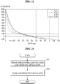
- FIGS. 12 and 13 are graphs illustrating the stress profiles of the glass after being subjected to the second ion exchange process according to various exemplary embodiments.
- a first curve PL11 represents the stress profile of the glass that was subjected to the first ion exchange process and then the second ion exchange process for approximately 30 minutes.
- a second curve PL12 represents the stress profile of the glass that was subjected to the first ion exchange process and then the second ion exchange process for approximately 60 minutes.
- a third curve PL13 represents the stress profile of the glass that was subjected to the first ion exchange process and then the second ion exchange process for approximately 90 minutes.
- a fourth curve PL14 represents the stress profile of the glass that was subjected to the first ion exchange process and then the second ion exchange process for approximately 120 minutes.
- the transition points, at which the slopes change sharply, vary depending on the period of time in which the second ion exchange process is carried out.
- the transition points of the first to fourth curves PL11 to PL14 are 9 ⁇ m, 12 ⁇ m, 15 ⁇ m and 17 ⁇ m, respectively. Accordingly, the depths of the transition points tend to increase as the period of time of the second ion exchange process increases.
- a fifth curve PL21 represents the stress profile of the glass that was subjected to the first ion exchange process, a stress-relieving process and then the second strengthening process for approximately 30 minutes.
- a sixth curve PL22 represents the stress profile of the glass that was subjected to the first ion exchange process, the stress-relieving process and then the second strengthening process for approximately 120 minutes.
- a seventh curve PL23 represents the stress profile of the glass that was subjected to the first ion exchange process, and then the second strengthening process for approximately 60 minutes, without the stress-relieving process.
- An eighth curve PL24 represents the stress profile of the glass that was subjected to the first ion exchange process, and then the second strengthening process for approximately 90 minutes, without the stress-relieving process.
- the transition points can be controlled also by adding the stress-relieving process. Specifically, as can be seen from the fifth curve PL21 and the sixth curve PL22, even if the stress-relieving process is further carried out, the positions of the transition points can be changed by controlling the duration of the second strengthening process. Further, as indicated by the seventh curve PL23 and the eighth curve PL24, the positions of the transition points can be easily controlled by controlling the period of time the second strengthening step even if the stress-relieving process is not further performed.
- FIG. 14 is a flowchart for illustrating a method for producing a glass article according to another exemplary embodiment of the present disclosure.
- a method for producing a glass article includes preparing a strengthened glass including a low-refractive surface layer (step S21), and polishing the low-refractive surface layer (step S22).
- step S21 The preparing the strengthened glass including the low-refractive surface layer (step S21) is identical to that of the exemplary embodiments of FIGS. 5 and 6 ; and, therefore, the redundant description will be omitted.
- the low-refractive surface layer is polished (step S22).
- FIG. 15 is a cross-sectional view showing a polishing process of the strengthened glass.
- the polishing process may be carried out by a chemical mechanical polishing method.
- the first surface US and the second surface RS of the strengthened glass 130 to be processed are polished using a chemical mechanical polishing apparatus 510 and a polishing slurry 520.
- the first surface US and the second surface RS may be polished sequentially as well.
- the strengthened glass 101 may be placed such that the second surface RS faces the stage (not shown) of the chemical mechanical polishing apparatus 510, the first surface US exposed upward is polished, and then the strengthened glass 101 is turned over such that the second surface RS is polished.
- the first surface US or the second surface RS may be subjected to the polishing process.
- the polishing thickness may be adjusted, for example, in the range of 100 nm to 1,000 nm (e.g., approximately 500 nm).
- the first and second surfaces may be polished to the same depth or different depths.
- FIG. 16 is an image showing a cross section of the glass article after the polishing process has been completed.
- the first surface US and the second surface RS of the glass article 102 are removed by polishing the low-refractive surface layer, but the side surfaces SS are not removed in doing so, such that the low-refractive surface layer 131 may remain on the side surfaces SS.
- a first surface US and a second surface RS of a glass article 102 are identical to those of the glass article shown in FIG. 2 .
- side surfaces SS are different in that the side surfaces SS include the low-refractive surface layer 131.
- the thickness of the low-refractive surface layer 131 remaining on the side surfaces SS may range from 100 nm to 500 nm. Even after the polishing process, some portion of the low-refractive surface layer may remain on the first surface US or the second surface RS. The thickness of the low-refractive surface layer remaining on the first surface US or the second surface RS may be smaller than the thickness of the low-refractive surface layer 131 remaining on the side surfaces SS.
- the low-refractive surface layer 131 remains on the side surfaces SS of the glass article 102, there may be fine cracks or variations in optical characteristics.
- the side surfaces SS of the glass article 102 do not contribute greatly to light transmission. Therefore, the fine cracks on the side surfaces SS have little effect on the overall strength of the glass article 102. Therefore, the glass article 102 of FIG. 16 can also have the optical characteristics and strength comparable to those of the exemplary embodiment of FIG. 2 .
- polishing process according to the exemplary embodiment of the present disclosure can also be utilized to achieve the uniform compressive stress characteristics at the first surface and the second surface of the glass article.
- the floating method which is one of the techniques for producing a glass plate, is carried out by flowing glass compositions into a tin bath.
- the surface of the glass plate in contact with the bath may have different compositions from the surface not in contact with the bath.
- the surface of the glass to an appropriate thickness by polishing, it is possible to reduce the deviations in the compressive stresses between the surfaces.
- the polishing process it is possible to select whether or not to polish each surface, and the polishing thickness of the first surface and the second surface can be adjusted differently.
- the compressive stress of the surface in contact with the tin bath and the surface not in contact with the tin bath can be controlled individually. For example, by polishing more the surface with relatively high compressive stress, it is possible to more easily control the deviations in the compressive stress between the surfaces.
- the polishing of the surface of the glass article may be used in combination with the etching.
- the first surface may be polished to reduce the compressive stress at the first surface so that it becomes substantially equal to the compressive stress at the second surface.
- the polishing process may be carried out to reduce deviations in the compressive stress between the surfaces.
- the glass article 102 is polished using the polishing slurry 520, there may be a certain surface roughness depending on the particle size of the polishing slurry 520.
- FIG. 17 is an image of glass article sample 1 when viewed from the top.
- FIG. 18 is an image of glass article sample 2 when viewed from the top.
- FIGS. 17 and 18 It can be seen from FIGS. 17 and 18 that there are fine patterns on the surfaces of both of the samples after the polishing process.
- the value of surface roughness Ra and the values of surface roughness Rz of glass article samples 1 and 2 were obtained.
- the glass article before the polishing had the value of Ra of 0.444 nm and the value of Rz of 7.1297 nm.
- Glass article sample 1 after the polishing had the value of Ra of 1.633 nm and the value of Rz of 44.286 nm.
- Glass article sample 2 after the polishing had the value of Ra of 1.404 nm and the value of Rz of 22.928 nm.
- the roughness was slightly increased by the polishing, it still lies within the range of 0.5 nm to 50 nm, which allows for the transmittance. Thus, it can be seen that the increase in the roughness due to the polishing hardly affects the optical characteristics of the glass article.
- iron ball drop tests were conducted on several glass article samples.
- the iron ball drop tests were carried out by dropping approximately 150 g of an iron (Fe) ball onto the glass article samples to measure the drop height to break the glass article samples. The higher the drop height is, the higher the strength of the glass article sample is, which means that the sample can withstand stronger impact.
- FIGS. 19 to 21 are graphs showing the results of the ball drop tests on the glass articles according to various exemplary embodiments.
- the glass article samples of FIG. 19 had been subjected to a first ion exchange process in a neutral salt consisting of 70 wt% potassium nitrate (KNO 3 ) and approximately 30 wt% sodium nitrate (NaNO3) at a temperature of approximately 530°C, and then a second ion exchange process in a neutral salt consisting of approximately 100 wt% potassium nitrate (KNO 3 ) at a temperature of approximately 420°C.
- KNO 3 potassium nitrate
- NaNO3 sodium nitrate
- the glass article samples of FIG. 20 had been subjected to a first ion exchange process in a neutral salt consisting of 70 wt% potassium nitrate (KNO 3 ) and approximately 30 wt% sodium nitrate (NaNO3) at a temperature of approximately 530°C, heat treatment at a temperature of approximately 530°C, and again a second ion exchange process in a neutral salt consisting of approximately 100 wt% potassium nitrate (KNO 3 ) at a temperature of approximately 420°C.
- a neutral salt consisting of 70 wt% potassium nitrate (KNO 3 ) and approximately 30 wt% sodium nitrate (NaNO3) at a temperature of approximately 530°C
- heat treatment at a temperature of approximately 530°C
- a second ion exchange process in a neutral salt consisting of approximately 100 wt% potassium nitrate (KNO 3 ) at a temperature of approximately 420°C.
- the glass article samples of FIG. 21 had been subjected to a first ion exchange process in a neutral salt consisting of 70 wt% potassium nitrate (KNO 3 ) and approximately 30 wt% sodium nitrate (NaNO3) at a temperature of approximately 530°C, heat treatment at a temperature of approximately 530°C, and again a second ion exchange process in a neutral salt consisting of approximately 100 wt% potassium nitrate (KNO 3 ) at a temperature of approximately 420°C. It is, however, to be noted that the heat treatment was carried out for two times longer than the glass article samples of FIG. 20 .
- breakage heights of the glass article samples before the etching were relatively wide, ranging from approximately 35 cm to about 95 cm. Among them, as can be seen from the valid data (data belonging to the boxes of the drawing), the breakage heights of the samples before the etching were approximately 45 cm to 67 cm. In contrast, the breakage heights of the samples after the etching were uniform, i.e., 110 cm.
- breakage heights of the glass article samples before the etching were relatively wide, ranging from approximately 20 cm to about 90 cm. Among them, as can be seen from the valid data (data belonging to the boxes of the drawing), the breakage heights of the samples before the etching were approximately 35 cm to 60 cm. The breakage heights of the samples after the etching were approximately 100 to 110 cm.
- the breakage heights of the glass article samples before the etching were approximately 70 cm to 90 cm, with respect to the valid data (data belonging to the boxes of the drawing).
- the breakage heights of the samples after the etching were uniform, i.e., 110 cm.
- FIG. 22 is a graph showing the compressive stresses of glass article samples before and after the etching process.
- FIG. 23 is a graph showing the compression depth of the glass article samples before and after the etching process.
- the average of the compressive stresses of the glass article samples before the etching was approximately 957 MPa, while the average of the compressive stresses of the glass article samples after the etching was approximately 890 MPa, which was reduced by 60 MPa to 70 MPa in general. The distribution of the compressive stresses became narrower after the etching.
- the average of the compression depths of the glass article samples before the etching was approximately 78.3 ⁇ m, while the average of the compression depths of the glass article samples after the etching was approximately 78.2 ⁇ m. Considering the measurement errors, it is interpreted that there is no significant difference in the compression depth before and after the etching.
- FIG. 24 is a graph showing the compressive stresses of glass article samples before and after the polishing process.
- FIG. 25 is a graph showing the compressive depth of glass article samples before and after the polishing process.
- the average of the compressive stresses of the glass article samples before the polishing was approximately 928 MPa, while the average of the compressive stresses of the glass article samples after the polishing was approximately 897 MPa, which was reduced by 10 MPa to 50 MPa in general.
- the distribution of the compressive stresses became narrower after the polishing.
- the average of the compression depths of the glass article samples before the polishing was approximately 74 ⁇ m
- the average of the compression depths of the glass article samples after the polishing was approximately 74 ⁇ m, which is almost equal to the average before the polishing.
- embodiments of the invention may provide a method for producing a glass article, the method comprising: preparing glass to be processed, the glass comprising a glass bulk and a low-refractive surface layer disposed on the glass bulk; and etching away the low-refractive surface layer to form an etched glass, wherein the etching away the low-refractive surface layer comprises: cleaning (or washing or immersing) the low-refractive surface layer with an acid solution; and cleaning (or washing or immersing) the low-refractive surface layer with a base solution after the cleaning it with the acid solution.
- the method may comprise forming the low-refractive surface layer using an ion exchange to strengthen the glass.
- the low-refractive surface layer may include fine pores or fine grooves therein. The fine pores or fine grooves may be filled with the air to lower the average refractive index of the low-refractive surface layer.
- the low-refractive surface layer 130 may be a silicon rich layer.
- the low-refractive surface layer may have a silicon content higher than that of the bulk of the strengthened glass.
- the silicon content of the low-refractive surface layer may be higher because the alkali metal or alkaline earth metal is removed during a high-temperature salt treatment process for ion exchange of the strengthened glass.
- the cleaning with the acid solution may be carried out for 0.5 to 5 minutes using an acidic solution containing nitric acid in an amount between 2 wt% and 5 wt%, and the cleaning with the base solution may be carried out for 0.5 to 5 minutes using a base solution containing sodium hydroxide in an amount between 2 wt% and 5 wt%.
- the low-refractive surface layer is substantially not removed during the cleaning with the acid solution, and is substantially removed during the cleaning with the base solution.
- embodiments of the invention may provide a method for producing a glass article, the method comprising: preparing glass to be processed, the glass comprising a glass bulk and a low-refractive surface layer disposed on the glass bulk; and polishing a surface of the glass to form a polished glass, wherein the polishing the surface of the glass comprises: removing at least partially the low-refractive surface layer.
- the method may comprise forming the low-refractive surface layer using an ion exchange to strengthen the glass.
- the low-refractive surface layer may include fine pores or fine grooves therein. The fine pores or fine grooves may be filled with the air to lower the average refractive index of the low-refractive surface layer.
- the low-refractive surface layer 130 may be a silicon rich layer.
- the low-refractive surface layer may have a silicon content higher than that of the bulk of the strengthened glass.
- the silicon content of the low-refractive surface layer may be higher because the alkali metal or alkaline earth metal is removed during a high-temperature salt treatment process for ion exchange of the strengthened glass.
- embodiments of the invention may provide a method for producing a glass article, the method comprising: preparing glass to be processed that has a first surface and a second surface opposed to the first surface, wherein the glass has a first maximum compressive stress at the first surface and a second maximum compressive stress at the second surface; and polishing the first surface and/or the second surface to reduce deviations between the first maximum compressive stress and the second maximum compressive stress.
- embodiments of the invention may provide a glass article comprising a glass comprising glass bulk and a low-refractive surface layer disposed on the glass bulk, the glass comprising a compressive region disposed adjacent to a surface of the glass and a tensile region disposed inside the glass, wherein a refractive index of the low-refractive surface layer is smaller than a refractive index of the glass bulk and is greater than a refractive index of air, wherein the low-refractive surface layer is disposed within the compressive region, and wherein a thickness of the low-refractive surface layer is less than 100 nm and is smaller than a compression depth of the compressive region.
- embodiments of the invention may provide a glass article comprising a glass comprising a first surface, a second surface opposed to the first surface and side surfaces, wherein the glass comprises a first compressive region having a first compression depth from the first surface, a second compressive region having a second compression depth from the second surface, and a tensile region disposed between the first compressive region and the second compressive region, wherein the glass comprises glass bulk and a side low-refractive surface layer disposed on side surfaces of the glass bulk, and wherein a refractive index of the side low-refractive surface layer is smaller than a refractive index of the glass bulk and greater than a refractive index of air.
Landscapes
- Chemical & Material Sciences (AREA)
- Engineering & Computer Science (AREA)
- Materials Engineering (AREA)
- Organic Chemistry (AREA)
- Chemical Kinetics & Catalysis (AREA)
- Geochemistry & Mineralogy (AREA)
- General Chemical & Material Sciences (AREA)
- Life Sciences & Earth Sciences (AREA)
- Mechanical Engineering (AREA)
- Ceramic Engineering (AREA)
- Inorganic Chemistry (AREA)
- Surface Treatment Of Glass (AREA)
- Re-Forming, After-Treatment, Cutting And Transporting Of Glass Products (AREA)
Abstract
Description
- The present disclosure relates to a glass article and a method for producing the same.
- Glass articles are widely used in electronic devices or construction materials including display devices. For example, glass articles are employed as a substrate for a flat display device such as a liquid-crystal display (LCD), an organic light-emitting display (OLED) and an electrophoretic display (EPD), or a window for protecting it.
- As portable electronic devices such as smart phones and tablet PCs prevail, a glass article employed thereby is frequently exposed to external impact. Accordingly, what is required is a glass article that is thin and thus easy to carry and has good strength for withstanding external impact.
- Aspects of the present disclosure provide a method for producing a glass article having a good strength.
- Aspects of the present disclosure also provide a glass article having a good strength.
- It should be noted that objects of the present disclosure are not limited to the above-mentioned object; and other objects of the present invention will be apparent to those skilled in the art from the following descriptions.
- According to an aspect of the present disclosure, there is provided a method for producing a glass article, the method including preparing a glass to be processed, the glass comprising a glass bulk and a low-refractive surface layer disposed on the glass bulk, and etching away the low-refractive surface layer to form an etched glass, wherein the etching away the low-refractive surface layer comprises: cleaning the low-refractive surface layer with an acid solution; and cleaning the low-refractive surface layer with a base solution after the cleaning it with the acid solution.
- In some embodiments, the low-refractive surface layer is substantially not removed during the cleaning with the acid solution, and is substantially removed during the cleaning with the base solution.
- In some embodiments, thickness of the low-refractive surface layer of the glass ranges from 100 to 500 nm.
- In some embodiments, the etching away the low-refractive surface layer to form an etched glass comprises removing the low-refractive surface layer completely.
- In some embodiments, the thickness of the low-refractive surface layer is less than 100 nm after the etching away the low-refractive surface layer to form an etched glass.
- In some embodiments, a refractive index of the low-refractive surface layer is smaller than a refractive index of the glass bulk and is greater than a refractive index of air.
- In some embodiments, the glass comprises a compressive region disposed adjacent to a surface thereof and a tensile region disposed inside it, wherein the low-refractive surface layer is disposed in the compressive region, and wherein a thickness of the low-refractive surface layer is smaller than a compression depth of the compressive region.
- In some embodiments, a maximum compressive stress of the etched glass is less than a maximum compressive stress of the glass.
- In some embodiments, a difference between the maximum compressive stress of the glass and the maximum compressive stress of the etched glass ranges from 10 MPa to 100 MPa.
- In some embodiments, a compression depth of the etched glass is substantially equal to the compression depth of the glass.
- In some embodiments, a maximum tensile stress (CT1) of the etched glass satisfies

- In some embodiments, a maximum tensile stress of the glass satisfies

- In some embodiments, the compressive region has the maximum compressive stress at a surface of the low-refractive surface layer.
- According to another aspect of the present disclosure, there is provided a method for producing a glass article including preparing a glass to be processed, the glass comprising a glass bulk and a low-refractive surface layer disposed on the glass bulk, and polishing a surface of the glass to form a polished glass, wherein the polishing the surface of the glass comprises: removing at least partially the low-refractive surface layer.
- In some embodiments, the glass comprises a first surface and a second surface opposed to the first surface, and wherein the polishing the surface of the glass comprises: polishing the first surface, and polishing the second surface.
- In some embodiments, a thickness of the polished surface ranges from 100 nm to 1,000 nm.
- In some embodiments, a roughness of the surface of the polished glass ranges from 0.5 nm to 50 nm.
- In some embodiments, a thickness of the low-refractive surface layer of the glass ranges from 100 nm to 500 nm.
- In some embodiments, a refractive index of the low-refractive surface layer is smaller than a refractive index of the glass bulk and is greater than a refractive index of air.
- In some embodiments, the glass comprises a compressive region disposed adjacent to a surface thereof and a tensile region disposed inside it, wherein the low-refractive surface layer is disposed in the compressive region, and wherein a thickness of the low-refractive surface layer is smaller than a compression depth of the compressive region.
- In some embodiments, a maximum compressive stress of the polished glass is less than a maximum compressive stress of the glass.
- In some embodiments, a difference between the maximum compressive stress of the glass and the maximum compressive stress of the polished glass ranges from 10 MPa to 100 MPa.
- In some embodiments, a compression depth of the polished glass is substantially equal to the compression depth of the glass.
- In some embodiments, a maximum tensile stress (CT1) of the polished glass satisfies

- In some embodiments, a maximum tensile stress of the glass satisfies

- In some embodiments, the compressive region has the maximum compressive stress at a surface of the low-refractive surface layer.
- According to another aspect of the present disclosure, there is provided a method for producing a glass article including preparing a glass to be processed that has a first surface and a second surface opposed to the first surface, wherein the glass has a first maximum compressive stress at the first surface and a second maximum compressive stress at the second surface, and polishing the first surface and/or the second surface to reduce deviations between the first maximum compressive stress and the second maximum compressive stress.
- In some embodiments, the glass is produced by a floating technique, and wherein the first surface of the glass comes in contact with a floating fluid, and the second surface of the glass does not come in contact with the floating fluid.
- According to an aspect of the present disclosure, there is provided a glass article comprising a glass comprising glass bulk and a low-refractive surface layer disposed on the glass bulk, the glass comprising a compressive region disposed adjacent to a surface of the glass and a tensile region disposed inside the glass, wherein a refractive index of the low-refractive surface layer is smaller than a refractive index of the glass bulk and is greater than a refractive index of air, wherein the low-refractive surface layer is disposed within the compressive region, and wherein a thickness of the low-refractive surface layer is less than 100 nm and is smaller than a compression depth of the compressive region.
- In some embodiments, the compressive region has the maximum compressive stress at a surface of the low-refractive surface layer.
- According to another aspect of the present disclosure, there is provide a glass article comprising a glass comprising a first surface, a second surface opposed to the first surface and side surfaces, wherein the glass comprises a first compressive region having a first compression depth from the first surface, a second compressive region having a second compression depth from the second surface, and a tensile region disposed between the first compressive region and the second compressive region, wherein the glass comprises glass bulk and a side low-refractive surface layer disposed on side surfaces of the glass bulk, and wherein a refractive index of the side low-refractive surface layer is smaller than a refractive index of the glass bulk and greater than a refractive index of air.
- In some embodiments, the glass has substantially same refractive index from the first surface to the second surface.
- In some embodiments, a thickness of the side low-refractive surface layer ranges from 100 nm to 500 nm.
- In some embodiments, the glass article further comprises: a first low-refractive surface layer disposed on the first surface of the glass bulk, wherein the first low-refractive surface layer is made of a same material as the side low-refractive surface layer, and wherein a thickness of the first low-refractive surface layer is smaller than a thickness of the side low-refractive surface layer.
- In some embodiments, a roughness of each of the first surface and the second surface ranges from 0.5 nm to 50 nm.
- According to an aspect of the invention, there is provided a method for producing a glass article as set out in
claim 1. Preferred features of this aspect are set out in claims 2 and 3 and claims 7 to 12. According to an aspect of the invention, there is provided a method for producing a glass article as set out inclaim 4. Preferred features of this aspect are set out in claims 5 to 12. According to an aspect of the invention, there is provided a method for producing a glass article as set out in claim 13. Preferred features of this aspect are set out in claim 14. According to an aspect of the invention, there is provided a glass article as set out inclaim 15. Preferred features of this aspect are set out in claim 16. According to an aspect of the invention, there is provided a glass article as set out in claim 17. Preferred features of this aspect are set out claims 18 to 20. - The details of one or more embodiments of the subject matter described in this specification are set forth in the accompanying drawings and the description below.
- According to an exemplary embodiment of the present disclosure, a glass article can have a high strength which is not easily broken by an external impact. According to an exemplary embodiment of the present disclosure, a glass article having a high strength can be produced by an easy method.
- It should be noted that effects of the present disclosure are not limited to those described above and other effects of the present disclosure will be apparent to those skilled in the art from the following descriptions.
- The above and other aspects and features of the present disclosure will become more apparent by describing in detail exemplary embodiments thereof with reference to the attached drawings, in which:
-
FIG. 1 is a perspective view of glass articles according to various exemplary embodiments; -
FIG. 2 is a cross-sectional view of a glass article having the shape of a flat plate according to an exemplary embodiment of the present disclosure; -
FIG. 3 is a graph showing the stress profile of a glass article according to an exemplary embodiment of the present disclosure; -
FIG. 4 is a schematic diagram illustrating an ion exchange process according to an exemplary embodiment of the present disclosure; -
FIG. 5 is a flowchart for illustrating a method for producing a glass article according to an exemplary embodiment of the present disclosure; -
FIG. 6 is a cross-sectional view of a strengthened glass including a low refractive surface layer; -
FIG. 7 is a cross-sectional view showing an acid cleaning process of the strengthened glass; -
FIG. 8 is a cross-sectional view showing a base cleaning process of strengthened glass; -
FIG. 9 is a graph showing the stress profile before and after the etching process; -
FIGS. 10 and 11 are images when viewed from the top for comparing the surfaces of the glass articles according to the etching techniques; -
FIGS. 12 and13 are graphs illustrating the stress profiles of the glass after being subjected to the second ion exchange process according to various exemplary embodiments; -
FIG. 14 is a flowchart for illustrating a method for producing a glass article according to another exemplary embodiment of the present disclosure; -
FIG. 15 is a cross-sectional view showing a polishing process of the strengthened glass; -
FIG. 16 is an image showing a cross section of the glass article after the polishing process has been completed; -
FIG. 17 is an image ofglass article sample 1 when viewed from the top; -
FIG. 18 is an image of glass article sample 2 when viewed from the top; -
FIGS. 19 to 21 are graphs showing the results of the ball drop tests on the glass articles according to various exemplary embodiments; -
FIG. 22 is a graph showing the compressive stresses of glass article samples before and after the etching process; -
FIG. 23 is a graph showing the compression depth of the glass article samples before and after the etching process; -
FIG. 24 is a graph showing the compressive stresses of glass article samples before and after the polishing process; and -
FIG. 25 is a graph showing the compressive depth of glass article samples before and after the polishing process. - Advantages and features of the present disclosure and methods of accomplishing the same may be understood more readily by reference to the following detailed description of exemplary embodiments and the accompanying drawings. The present disclosure may, however, be embodied in many different forms and should not be construed as being limited to the exemplary embodiments set forth herein. Rather, these exemplary embodiments are provided so that this disclosure will be thorough and complete and will fully convey the concept of the present disclosure to those skilled in the art, and the present disclosure will only be defined within the scope of the appended claims.
- It will be understood that when an element or layer is referred to as being "on", "connected to" or "coupled to" another element or layer, it can be directly on, connected or coupled to the other element or layer or intervening elements or layers may be present. In the drawings, like reference numerals indicate like elements. As used herein, the term "and/or" includes any and all combinations of one or more of the associated listed items.
- As used herein, "glass article" refers to an article that is entirely or partially made of glass.
- Exemplary embodiments of the present disclosure will hereinafter be described with reference to the accompanying drawings.
- The glass is used as a window for protecting a display, a substrate for a display panel, a substrate for a touch panel, an optical member such as a light guide plate, etc. in electronic devices including a display, such as a tablet PC, a notebook PC, a smart phone, an electronic book, a television and a PC monitor as well as a refrigerator and a cleaning machine including a display screen. Glass may also be employed as a cover glass for an instrument panel in a vehicle, a cover glass for solar cells, interior materials for construction materials, windows for buildings and houses, etc.
- Some glass articles are required to have high strength. For example, when glass is employed as a window, it is desirable to have a small thickness and a high strength that is not easily broken by an external impact since it is required to have a high transmittance and a small weight. Glass having a high strength can be produced by, for example, chemical strengthening or thermal strengthening. Examples of strengthened glass are shown in
FIG. 1 . -
FIG. 1 is a perspective view of glass articles according to various exemplary embodiments. - Referring to
FIG. 1 , in an exemplary embodiment, theglass article 100 may have the shape of a flat sheet or a flat plate. In another exemplary embodiment, theglass articles glass articles glass articles glass article 100. It is, however, to be understood that the embodiments of the present disclosure are not limited thereto. -
FIG. 2 is a cross-sectional view of a glass article having the shape of a flat plate according to an exemplary embodiment of the present disclosure. - Referring to
FIG. 2 , theglass article 100 includes a plurality of surfaces US, RS and SS. The surface of the glass article may include a first surface US, a second surface RS and side surfaces SS. In theglass article 100 having the shape of a flat plate, the first surface US and the second surface RS are main surfaces having a large area (e.g., an upper surface and a lower surface), and side surfaces SS are outer surfaces connecting the first surface US with the second surface RS. - The first surface US and the second surface RS are opposed to each other in the thickness (t) direction. When the
glass article 100 serves to transmit light like a window of a display, the light may be mainly incident on the first surface US or the second surface RS to exit through the other. - The thickness t of the
glass article 100 is defined as the distance between the first surface US and the second surface RS. The thickness t of theglass article 100 may range, but is not limited to in embodiments of the invention, from 0.1 to 2 mm. In an exemplary embodiment, the thickness t of theglass article 100 may be approximately 0.8 mm or less. In another exemplary embodiment, the thickness t of theglass article 100 may be approximately 0.65 mm or less. In yet another exemplary embodiment, the thickness t of theglass article 100 may be approximately 0.55 mm or less. In yet another exemplary embodiment, the thickness t of theglass article 100 may be approximately 0.5 mm or less. In yet another exemplary embodiment, the thickness t of theglass article 100 may be approximately 0.3 mm or less. Although theglass article 100 has the uniform thickness t, it may have different thicknesses for different regions. - The strengthened
glass article 100 includes compressive regions CSR1 and CSR2 and a tensile region CTR. The compressive regions CSR1 and CSR2 refer to regions where compressive stress act, and the tensile region CTR refer to a region where tensile stress acts. The compressive regions CSR1 and CSR2 are disposed adjacent to the surfaces US, RS and SS of theglass article 100. The tensile region CTR is disposed in the inside (or center) of theglass article 100. The compressive regions may be disposed adjacent to the side surfaces SS as well as the first surface US and the second surface RS. The depths (compression depths) of the compressive regions CSR1 and CSR2 extending in the depth direction from each of the surfaces US, RS and SS may be, but is not limited to being in embodiments of the invention, substantially uniform. The tensile region CTR may be surrounded by the compressive regions CSR1 and CSR2. -
FIG. 3 is a graph showing the stress profile of a glass article according to an exemplary embodiment of the present disclosure. In the graph ofFIG. 3 , the x-axis represents the thickness (t) direction of theglass article 100. InFIG. 3 , the compressive stress has positive values, while the tensile stress has negative values. Herein, the magnitude of the compressive/tensile stress means the absolute value regardless of its sign. - Referring to
FIGS. 2 and3 , theglass article 100 includes a first compressive region CSR1 that is extended from the first surface US to a first depth (a first compression depth DOL1), and a second compressive region CSR2 that is extended from the second surface RS to a second depth (a second compression depth DOL2). A tensile region CTR is disposed between the first compression depth DOL1 and the second compression depth DOL2. Although not shown inFIG. 3 , a compressive region and a tensile region may be disposed between opposed side surfaces SS of theglass article 100 in a similar manner. - The first compressive region CSR1 and the second compressive region CSR2 are resistant to an external impact, thereby suppressing cracks in the
glass article 100 or damage to theglass article 100. It can be said that the larger the maximum compression stresses CS1 and CS2 of the first and second compressive regions CSR1 and CSR2 are, the higher the strength of theglass article 100 is. Since an external impact is usually transmitted through the surfaces US, RS and SS of theglass article 100, it is advantageous to have the maximum compressive stresses CS1 and CS2 at the surfaces US, RS and SS of theglass article 100 in terms of durability. The maximum compressive stresses CS1 and CS2 of the first and second compressive regions CSR1 and CSR2 may be 700 MPa or more. For example, the maximum compressive stresses CS1 and CS2 of the first and second compressive regions CSR1 and CSR2 may be in the range of 800 MPa to 1,050 MPa. In an exemplary embodiment, the maximum compressive stresses CS1 and CS2 of the first and second compressive regions CSR1 and CSR2 may be in the range of 850 MPa to 1,000 MPa. - The first compression depth DOL1 and the second compression depth DOL2 suppress cracks or grooves formed in the first and second surfaces US and RS from propagating to the tensile region CTR inside the
glass article 100. The larger the first and second compression depths DOL1 and DOL2 are, the better the propagation of cracks and the like can be prevented. - The first and second compression depths DOL1 and DOL2 may be in the range of 20 µm to 150 µm. In an exemplary embodiment, the first and second compression depths DOL1 and DOL2 may be in the range of 50 µm to 100 µm. In a particular exemplary embodiment, the first and second compression depths DOL1 and DOL2 may range from 70 to 85 µm.
- In some exemplary embodiments, the first and second compression depths DOL1 and DOL2 may satisfy the following relationship with respect to the thickness t of the
glass article 100, although not limited thereto:
- In the exemplary embodiment of
FIG. 3 , the compressive stresses of the first compressive region CSR1 and the second compressive region CSR2 are the largest at the surfaces US and RS (see CS1 and CS2), respectively, and decrease toward the inside. Such stress profile may be obtained via an ion exchange process. The ion exchange process refers to a process of exchanging ions in theglass article 100 with other ions. By performing the ion exchange process, the ions at or near the surfaces US, RS, SS of theglass article 100 can be replaced or exchanged with larger ions having the same valence or oxidation state. For example, when theglass article 100 contains a monovalent alkali metal such as Li+, Na+, K+ and Rb+, the monovalent cation on the surface may be replaced by Na+, K+, Rb+, or Cs+ ions with larger ionic radius. -
FIG. 4 is a schematic diagram illustrating an ion exchange process according to an exemplary embodiment of the present disclosure.FIG. 4 shows that sodium ions (Na+) inside the glass are exchanged with potassium ions (K+). - Referring to
FIG. 4 , when the glass containing sodium ions is exposed to potassium ions by, for example, immersing the glass in a molten salt bath containing potassium nitrate (KNO3), sodium ions in the glass are discharged to the outside and the potassium ions can replace them. The exchanged potassium ions generate compressive stress because they have larger ionic radius than sodium ions. The more potassium ions are exchanged, the greater the compressive stress becomes. Since the ion exchange takes place through the surface of the glass, the amount of potassium ions (i.e., density) on the glass surface is the greatest. Although some of the exchanged potassium ions may diffuse into the glass to increase the compression depth, the amount (density) may be generally reduced away from the surface. Thus, the glass may have the stress profile that has the greatest compressive stress on the surface and decreases toward the inside. However, the exemplary embodiments are not limited to the above examples. The stress profile may be modified depending on the temperature, time and the number of the ion exchange process, whether heat treatment is carried out, etc. - Referring again to
FIGS. 2 and3 , theglass article 100 has a neutral stress (the stress value substantially equal to zero) at the first compression depth DOL1 and the second compression depth DOL2, and has tensile stress on the inner side. The tensile stress may be constant or increased toward the center. - The absolute value of the slope of the compressive stress in the stress profile may be greater than the absolute value of the slope of the tensile stress. On the inner side of the
glass article 100, there may be a wide section exhibiting tensile stress and having the average slope of zero. The width of the section of the tensile region CTR in which the average slope is zero (i.e., the thickness of the glass article) may be, but is not limited to being, larger than the first and second compression depths DOL1 and DOL2. - The tensile stress in the tensile region CTR may balance the compression stresses of the first and second compressive regions CSR1 and CSR2. That is to say, in the
glass article 100, the sum of the compressive stresses may be equal to the sum of tensile stresses. When the stress profile in theglass article 100 is represented by the function f(x), the following relationship can be established:
- For the
glass article 100 in which the maximum compression stresses CS1 and CS2 and the compression depths DOL1 and DOL2 of the first compression region CSR1 and the second compression region CSR2 are equal to each other and their profiles approximate a triangular shape, and the profile of the tensile region CTR generally approximates a rectangular shape, the following relationship may be established:
- The larger the tensile stress inside the
glass article 100 is, the more likely the fragments to be vigorously released when theglass article 100 is broken, and the more likely theglass article 100 is to be crushed from the inside. The maximum tensile stress that meets the frangibility requirements of theglass article 100 may satisfy the following relationship:
- Although it is desired that the compressive stresses CS1 and CS2 and the compression depths DOL1 and DOL2 have large values in order to increase the strength of the
glass article 100, the tensile stress is also increased with the sum of the compressive stresses. In order to meet the frangibility requirements while having a high strength, it is desired to adjust the stress profile such that the maximum compressive stresses CS1 and CS2 and the compression depths DOL1 and DOL2 have large values while the sum of the compressive stresses (e.g., the area of the compressive regions inFIG. 3 ) becomes smaller. The stress profile in theglass article 100 can be controlled by an ion exchange process, a heat treatment process, a post-treatment process, or the like. Detailed descriptions on this will be given later on. - According to some exemplary embodiments of the present disclosure, the maximum tensile stress CT1 of the
glass article 100 can satisfy the condition ofEquation 4 above within the range defined by Equation 5 below:
- According to an exemplary embodiment of the present disclosure, the
glass article 100 may have no low-refractive surface layer on the first surface US and the second surface RS or may have a low-refractive surface layer having a very small thickness (e.g., less than 100 nm). This is in contrast to glass having a low-refractive surface layer with a thickness of 100 nm to 500 nm on the surface via an ion exchange process. Theglass article 100 according to the exemplary embodiment of the present disclosure may be produced by preparing a strengthened glass including a low-refractive surface layer and removing all or a part of the low-refractive surface layer. Removing the low-refractive surface layer may be carried out by etching or polishing. More detailed description thereon will be given below with respect to the following exemplary embodiments. -
FIG. 5 is a flowchart for illustrating a method for producing a glass article according to an exemplary embodiment of the present disclosure. - Referring to
FIG. 5 , according to an exemplary embodiment of the present disclosure, a method for producing a glass article includes preparing a strengthened glass including a low-refractive surface layer (step S11), and etching away the low-refractive surface layer (step S12). -
FIG. 6 is a cross-sectional view of a strengthened glass including a low-refractive surface layer. - Referring to
FIG. 6 , the strengthenedglass 101 may be obtained via an ion exchange process. A method for producing the strengthenedglass 101 will be described in detail later. - The ion exchange process can introduce compressive stress in the vicinity of the surface of the glass while forming a low-
refractive surface layer 130 on the surface. The low-refractive surface layer 130 may be formed on all surfaces (the first surface US, the second surface RS, and the side surfaces SS) of the strengthenedglass 101. The low-refractive surface layer 130 is located on the surfaces US, RS and SS of the strengthenedglass 101 in the compressive regions CSR1 and CSR2. The low-refractive surface layer 130 has a thickness less than the compression depth. The thickness of the low-refractive surface layer 130 may range from 100 nm to 500 nm. The compressive regions CSR1 and CSR2 may have the maximum compressive stress at the surface of the low-refractive surface layer 130. - The low-
refractive surface layer 130 may not be distinguished by naked eyes from the bulk BLK of the strengthened glass 101 (the portion of the strengthened glass except the low-refractive surface layer). That is to say, unlike typical layer structures, the bulk BLK of the strengthenedglass 101 may not be distinguished from the low-refractive surface layer 130 by naked eyes. However, the low-refractive surface layer 130 may be distinguishable from the bulk BLK of the strengthenedglass 101 by an optical method, by compositions thereof, or the like. - The low-
refractive surface layer 130 has a lower refractive index than the refractive index of the bulk BLK of the strengthenedglass 101. The refractive index of the low-refractive surface layer 130 is larger than the refractive index of air and smaller than the refractive index of the bulk BLK of the strengthenedglass 101. When the refractive index of the bulk BLK of the strengthenedglass 101 is 1.5, the refractive index or the average refractive index of the low-refractive surface layer 130 may be equal to 1.48 or less, equal to 1.45 or less, and in some exemplary embodiments equal to 1.3 or less. The low-refractive surface layer 130 may form an optical interface with the bulk BLK of the strengthened glass. - The low-
refractive surface layer 130 may include fine pores or fine grooves therein. The fine pores or fine grooves may be filled with the air to lower the average refractive index of the low-refractive surface layer 130. - The low-
refractive surface layer 130 may be a silicon rich layer. The low-refractive surface layer 130 may have a silicon content higher than that of the bulk BLK of the strengthenedglass 101. The silicon content of the low-refractive surface layer 130 is higher because the alkali metal or alkaline earth metal is removed during a high-temperature salt treatment process for ion exchange of the strengthenedglass 101. In an exemplary embodiment, the ratio of the silicon content of the low-refractive surface layer 130 to the silicon content of the bulk BLK of the strengthenedglass 101 may be, but is not limited to, 1.2 to 1.4. - The low-
refractive surface layer 130 may be a sodium poor layer. Since the low-refractive surface layer 130 is located on the surfaces US, RS and SS of the strengthenedglass 101, the sodium may be largely discharged through the ion exchange, such that the sodium content of the low-refractive surface layer 130 may be significantly smaller that the sodium content of the bulk BLK of the strengthenedglass 101. - The low-
refractive surface layer 130 may include afine crack 135. Thefine crack 135 may be formed by a small friction, impact, or reaction with moisture in the air during the process of producing glass. Thefine crack 135 may be generated during a process of strengthening the glass and may become larger under high temperature conditions of the strengthening process. - The low-
refractive surface layer 130 is located at the outermost side of the strengthenedglass 101 and may include defects such as thefine crack 135. Such defects on the surface may lower the strength of the strengthenedglass 101. - Accordingly, according to an exemplary embodiment of the present disclosure, the method for producing glass article includes etching and removing the low-
refractive surface layer 130 of the strengthenedglass 101 which is to be processed. By removing the low-refractive surface layer 130, it is possible to improve the transmittance of the glass article 100 (seeFIG. 2 ), and overcome defects on the surface. As the low-refractive surface layer 130 is removed, the thickness of the glass article 100 (seeFIG. 2 ) may be somewhat reduced. - The etching the low-
refractive surface layer 130 may include an acid cleaning process and a base cleaning process. The acid cleaning process may be carried out using an acidic solution containing at least one of: inorganic acids such as hydrochloric acid, sulfuric acid, nitric acid and hydrogen fluoride; and organic acids such as formic acid, oxalic acid, citric acid, acetic acid, and benzoic acid. The base cleaning process may be carried out using a base solution containing at least one of: hydroxides of alkali metals such as sodium hydroxide, potassium hydroxide and lithium hydroxide; hydroxides of alkaline earth metal such as calcium hydroxide; inorganic alkali metal salts such as sodium carbonate; organic alkali metal salts such as sodium acetate, and ammonia water.FIGS. 7 and8 illustrate an acid cleaning process using an acidic solution containing nitric acid, and a base cleaning process using a basic solution containing sodium hydroxide, respectively. -
FIG. 7 is a cross-sectional view showing an acid cleaning process of the strengthened glass. - Referring to
FIG. 7 , the strengthenedglass 101 including the low-refractive surface layer 130 is cleaned with an acidic solution containing nitric acid (HNO3). Although the acid cleaning process may be carried out by immersing the strengthenedglass 101 into an acidic solution to stir it, it may also be carried out by spraying or other methods. - The content of nitric acid in the acid solution may be, e.g., approximately 6 wt% or less, e.g., approximately 2 wt% to 5 wt%. The pH of the acidic solution may range from 1 to 3. The acid cleaning process may be carried out at a temperature of 30°C to 50°C for 0.5 to 5 minutes or 2 to 4 minutes.
- Even after the above-described acid cleaning process has been completed, the low-
refractive surface layer 130 is hardly removed. -
FIG. 8 is a cross-sectional view showing a base cleaning process of strengthened glass. - After the acid cleaning process, the strengthened
glass 101 is cleaned with a basic solution containing sodium hydroxide (NaOH). Although the base cleaning process may be carried out by immersing the strengthenedglass 101 into a base solution to stir it, it may also be carried out by spraying or other methods. - The content of sodium hydroxide in the base solution may be, e.g., approximately 6 wt% or less, e.g., approximately 2 wt% to 5 wt%. The pH of the base solution may range from 12 to 14. The base cleaning process may be carried out at a temperature of 30°C to 50°C for 0.5 to 5 minutes or 2 to 4 minutes.
- After the base cleaning process has been completed, the surface of the strengthened
glass 101 may be etched to a depth of approximately 500 nm, such that the low-refractive surface layer 130 may be removed. Thefine crack 135 formed on the surface can also be removed together with the low-refractive surface layer 130. After the low-refractive surface layer 130 has been completely removed, a glass article as shown inFIG. 2 can be obtained. Theglass article 100 ofFIG. 2 may have no optical interface throughout theglass article 100 when compared to the strengthenedglass 101 ofFIG. 6 . In addition, defects on the surface are overcome and the strength is improved as the low-refractive surface layer 130 has been removed. - In some implementations, a part of the low-
refractive surface layer 130 may remain, in which case the thickness of the low-refractive surface layer 130 is still reduced. Since thefine crack 135 penetrate in the depth direction from the surface, such a fine crack may be removed or reduced if the low-refractive surface layer 130 is removed in the depth direction from the surface by the etching process. Accordingly, even if the low-refractive surface layer 130 remains at a small thickness of less than 100 nm, the strength of theglass article 100 can be enhanced by the etching process. - As described above, the low-
refractive surface layer 130 is removed mainly by the base cleaning process. However, when the base cleaning process alone is performed without the acid cleaning process, the low-refractive surface layer 130 is not efficiently etched away. It is believed that the acid cleaning process itself does not remove the low-refractive surface layer 130 but serves to transform the low-refractive surface layer 130 into a state that can be easily removed by the base cleaning process. For the same reason, it is preferable to carry out the acid cleaning process first and then the basic cleaning process. - The etching process including the acid cleaning and base cleaning processes mainly etches the low-
refractive surface layer 130. In an exemplary embodiment, the etch rate of the bulk BLK of the strengthenedglass 101 with respect to the cleaning solution is lower than the etch rate of the low-refractive surface layer 130. After the low-refractive surface layer 130 has been completely removed, the surface of the bulk BLK of the strengthened glass may be exposed to the cleaning solution depending on the concentration of the cleaning solution, time, temperature, etc. However, if the etch rate of the bulk BLK of the strengthened glass is low, it is possible to prevent the bulk BLK from being overly etched. - When the surface of the strengthened
glass 101 is etched, the stress profile inside it may change as well. -
FIG. 9 is a graph showing the stress profile before and after the etching process. For convenience of illustration, the stress profile is simplified inFIG. 9 . - Referring to
FIG. 9 , the strengthened glass has the maximum compressive stress CS1' at the surface before the etching. The maximum compressive stress also changes as the surface of the strengthened glass is removed by the etching process. As mentioned earlier, the compressive stress is proportional to the density of the exchanged ions. During the etching process, no ion is supplied newly, and the heat energy for diffusing ions is not so large. Thus, the position of the exchanged ions hardly changes. Therefore, the compressive stress at the surface can be maintained as the original profile, except the portion removed by the etching. If the original profile had a shape that decreased with thickness (depth), it would have the maximum compressive stress CS at the surface of the glass article even after the etching. - Since the surface of the strengthened glass having the maximum compressive stress CS1' before the etching is removed by the etching, the maximum compressive stress CS1 after the etching is lower than the maximum compressive stress CS1' before the etching. Although the thickness removed by the etching is merely a very small fraction of the compression depth, the reduction rate of the maximum compressive stress may vary depending on the slope of the compressive stress profile. If the slope of the compressive stress profile CS1' near the surface is steep, the maximum compressive stress CS1 may be significantly reduced even if a small thickness of the surface has been etched away.
- In an exemplary embodiment, the reduction rate of the maximum compressive stress by the etching ((CS1' - CS1)/CS1') may be equal to or less than 10%. The reduction in the maximum compressive stress (CS1' - CS1) by the etching may range from 10 MPa to 100 MPa. For example, the reduction (CS1' - CS1) may be in the range of 50 MPa to 100 MPa, or in the range of approximately 60 MPa to 70 MPa.
- As the maximum compressive stress CS1 decreases after the etching, the sum of the compressive stresses of the compressive regions can also be reduced. Accordingly, the sum of the tensile stresses of the tensile regions can also be reduced to satisfy Equation 2 above. As the sum of tensile stresses changes, the stress profile in the tensile region changes, and the neutral stress point also changes. As can be seen from results of the experiments, the first compression depth DOL1' before the etching is substantially the same as the first compression depth DOL1 after the etching, without any significant change. This means that the neutral stress point has moved to the inside of the strengthened glass.
- The maximum tensile stress can also be reduced as the sum of the tensile stresses is reduced by the etching. Embodiments of the present disclosure, however, are not limited thereto. The maximum tensile stress may be maintained if it is possible to compensate for the reduced stress only by a change in the neutral stress point and/or a change in the slope of the tensile stress profile.
- In an exemplary embodiment where the maximum tensile stress is reduced by the etching, the frangibility requirements of the glass article of
Equation 4 above is applied to the glass article after the etching. The strengthened glass before the etching, which is not a complete article yet, may not necessary have to meet the requirements. In view of the above, according to some exemplary embodiments of the present disclosure, the strengthened glass before the etching and the glass article after the etching may satisfy the following relationship:
- According to Equation 6 above, the strengthened glass can be produced under conditions exceeding the frangibility requirements according to
Equation 4, and the tensile stresses can be adjusted to satisfyEquation 4 by the etching. Embodiments of the present disclosure, however, are not limited thereto. The maximum tensile stresses CT1' and CT1 of the strengthened glass before as well as after the etching may satisfyEquation 4. -
FIGS. 10 and 11 are images when viewed from the top for comparing the surfaces of the glass articles according to the etching techniques.FIG. 10 is an image of a glass article obtained by performing an etching process on a strengthened glass with hydrofluoric acid (HF), taken by a scanning electron microscope (SEM).FIG. 11 is an image of a glass article obtained by performing an etching process on the strengthened glass according to the exemplary embodiments ofFIGS. 7 and11 , taken by a scanning electron microscope (SEM). - Hydrofluoric acid (HF) can also be effectively used to remove fine cracks on the surface of the strengthened glass. For example, a fine crack can be removed by processing the surface of the strengthened glass with hydrofluoric acid (HF), and polishing or etching away the periphery of the fine crack so that a gentle recess is formed around the fine crack. However, since the etching with hydrofluoric acid (HF) leaves recesses in the shape of rice grains on the surface of the glass article as shown in
FIG. 10 , the optical characteristics are degraded and the recesses can be seen by a user. - In contrast, if the etching is carried out with an acid solution containing nitric acid and a basic solution containing sodium hydroxide, fine cracks can be removed without leaving recesses in the shape of rice grains on the surface of the glass article, to provide a substantially flat surface as shown in
FIG. 11 . - Hereinafter, a method for producing strengthened glass will be described, which is prepared before the etching process of the low-refractive surface layer.
- Initially, the glass is prepared, which is not strengthened yet. The glass before it is strengthened may be produced by various techniques such as a floating method, a fusion method, and a slot down-draw method. The glass before it is strengthened may be an alkali aluminosilicate glass or the like. The compositions of the glass before it is strengthened may include SiO2 and Al2O3. The compositions of the glass before it is strengthened may further include Na2O. The compositions of the glass before it is strengthened may include at least one of K2O, B2O3, Li2O, MgO, CaO, ZnO, ZrO2, Fe2O3, SnO2 and P2O5. In some exemplary embodiments, the glass before it is strengthened may contain substantially no Li2O and P2O5. In some exemplary embodiments, the glass before it is strengthened may contain substantially no Li2O, P2O5 and B2O3. According to the exemplary embodiment, even if the glass article contains no Li2O, P2O5 and/or B2O3, it can have a compressive stress of 700 MPa or higher via the strengthening process and the process of removing the low-refractive surface layer and can have a sufficient depth for
satisfying Equation 1 above. - Subsequently, the glass is strengthened. The glass may be strengthened by a first ion exchange process and a second ion exchange process.
- The first ion exchange process may include exposing the glass to a molten salt containing potassium ions (K+). The molten salt may be, for example, a salt mixed with sodium nitrate (NaNO3) and potassium nitrate (KNO3). The first ion exchange process may be carried out at a temperature of ± 20°C, which is lower than the strain point by 50°C. For example, if the strain point of the glass is approximately 580°C, the first ion exchange process may be carried out at a temperature of approximately 500°C or higher (e.g., 530°C). The time for which the first ion exchange process is carried out may range, but is not limited to, 3 hours to 8 hours (e.g., approximately 5 hours). Through the first ion exchange process, potassium ions may enter the glass to introduce compressive stress near the surface of the glass.
- After the first ion exchange process, a stress-relieving process may be further carried out. The stress-relieving process may be carried out at a temperature of approximately 500°C or higher (e.g., approximately 530°C) for 1 to 3 hours (e.g., approximately 2 hours). Via the stress-relieving process, the maximum compressive stress may be reduced, and the potassium ions diffuse into the inside and the compression depth may be increased. The stress-relieving process may be carried out in air or in liquid. The stress-relieving process may be carried out in a liquid by immersing it into in a salt mixture of potassium ions and sodium ions to perform heat treatment. The stress-relieving process may be eliminated.
- After the stress-relieving process, the second ion exchange process is carried out. The second ion exchange process may be carried out by exposing the glass to a molten single salt containing potassium ions. The second ion exchange process may be carried out at a lower temperature and for a shorter time than the first ion exchange process. For example, the second ion exchange process may be carried out at a temperature from 380 °C to 460°C (e.g., approximately 420°C) for 1 to 3 hours or 1.3 to 2 hours.
- After the second ion exchange process is carried out, the compressive stress can be increased greatly at a shallow position of the surface of the glass.
- After the first ion exchange process, the stress-relieving process and second ion exchange process, the glass article may have a high surface compressive stresses and a sufficient compression depth. The compressive stress profile may have a steep slope near the surface of the glass article, and may have a slope becoming gentler toward the inside of the glass article. For example, the compressive stress profile may include a first section having the average slope (absolute value) of 40 MPa/µm to 200 MPa/µm from the surface to a first point, and a second section more distant from the surface than the first section and having the average slope (absolute value) equal to or less than 2 MPa/µm. Both the first section and the second section may lie within the compressive region. The first section may be extended from the surface to a depth exceeding 15 µm. In some exemplary embodiments, the compressive stress profile may include a point in the compressive region at which the average slope is 0 MPa/µm.
-
FIGS. 12 and13 are graphs illustrating the stress profiles of the glass after being subjected to the second ion exchange process according to various exemplary embodiments. - In the graph shown in
FIG. 12 , a first curve PL11 represents the stress profile of the glass that was subjected to the first ion exchange process and then the second ion exchange process for approximately 30 minutes. A second curve PL12 represents the stress profile of the glass that was subjected to the first ion exchange process and then the second ion exchange process for approximately 60 minutes. A third curve PL13 represents the stress profile of the glass that was subjected to the first ion exchange process and then the second ion exchange process for approximately 90 minutes. A fourth curve PL14 represents the stress profile of the glass that was subjected to the first ion exchange process and then the second ion exchange process for approximately 120 minutes. Referring toFIG. 12 , it can be seen that the transition points, at which the slopes change sharply, vary depending on the period of time in which the second ion exchange process is carried out. In the graph shown inFIG. 12 , the transition points of the first to fourth curves PL11 to PL14 are 9 µm, 12 µm, 15 µm and 17 µm, respectively. Accordingly, the depths of the transition points tend to increase as the period of time of the second ion exchange process increases. - In the graph shown in
FIG. 13 , a fifth curve PL21 represents the stress profile of the glass that was subjected to the first ion exchange process, a stress-relieving process and then the second strengthening process for approximately 30 minutes. A sixth curve PL22 represents the stress profile of the glass that was subjected to the first ion exchange process, the stress-relieving process and then the second strengthening process for approximately 120 minutes. A seventh curve PL23 represents the stress profile of the glass that was subjected to the first ion exchange process, and then the second strengthening process for approximately 60 minutes, without the stress-relieving process. An eighth curve PL24 represents the stress profile of the glass that was subjected to the first ion exchange process, and then the second strengthening process for approximately 90 minutes, without the stress-relieving process. - Referring to
FIG. 13 , it can be seen that the transition points can be controlled also by adding the stress-relieving process. Specifically, as can be seen from the fifth curve PL21 and the sixth curve PL22, even if the stress-relieving process is further carried out, the positions of the transition points can be changed by controlling the duration of the second strengthening process. Further, as indicated by the seventh curve PL23 and the eighth curve PL24, the positions of the transition points can be easily controlled by controlling the period of time the second strengthening step even if the stress-relieving process is not further performed. - A more detailed description and various embodiments of the above-mentioned method for producing strengthened glass are disclosed in Korean Patent Application No.
10-2017-0048080 -
FIG. 14 is a flowchart for illustrating a method for producing a glass article according to another exemplary embodiment of the present disclosure. - Referring to
FIG. 14 , according to the exemplary embodiment of the present disclosure, a method for producing a glass article includes preparing a strengthened glass including a low-refractive surface layer (step S21), and polishing the low-refractive surface layer (step S22). - The preparing the strengthened glass including the low-refractive surface layer (step S21) is identical to that of the exemplary embodiments of
FIGS. 5 and6 ; and, therefore, the redundant description will be omitted. - Subsequently, the low-refractive surface layer is polished (step S22).
-
FIG. 15 is a cross-sectional view showing a polishing process of the strengthened glass. - Referring to
FIG. 15 , the polishing process may be carried out by a chemical mechanical polishing method. Specifically, the first surface US and the second surface RS of the strengthenedglass 130 to be processed are polished using a chemicalmechanical polishing apparatus 510 and a polishingslurry 520. Although it is shown that the first surface US and the second surface RS are polished simultaneously, the first surface US and the second surface RS may be polished sequentially as well. For example, the strengthenedglass 101 may be placed such that the second surface RS faces the stage (not shown) of the chemicalmechanical polishing apparatus 510, the first surface US exposed upward is polished, and then the strengthenedglass 101 is turned over such that the second surface RS is polished. According to another exemplary embodiment of the present disclosure, the first surface US or the second surface RS may be subjected to the polishing process. - The polishing thickness may be adjusted, for example, in the range of 100 nm to 1,000 nm (e.g., approximately 500 nm). The first and second surfaces may be polished to the same depth or different depths.
-
FIG. 16 is an image showing a cross section of the glass article after the polishing process has been completed. - Referring to
FIG. 16 , the first surface US and the second surface RS of theglass article 102 are removed by polishing the low-refractive surface layer, but the side surfaces SS are not removed in doing so, such that the low-refractive surface layer 131 may remain on the side surfaces SS. Specifically, a first surface US and a second surface RS of aglass article 102 are identical to those of the glass article shown inFIG. 2 . However, side surfaces SS are different in that the side surfaces SS include the low-refractive surface layer 131. By removing the low-refractive surface layer from the first surface US and the second surface RS, no optical interface is formed in the thickness direction section from the first surface US to the second surface RS, so that the refractive index can be kept constant. The thickness of the low-refractive surface layer 131 remaining on the side surfaces SS may range from 100 nm to 500 nm. Even after the polishing process, some portion of the low-refractive surface layer may remain on the first surface US or the second surface RS. The thickness of the low-refractive surface layer remaining on the first surface US or the second surface RS may be smaller than the thickness of the low-refractive surface layer 131 remaining on the side surfaces SS. - As the low-
refractive surface layer 131 remains on the side surfaces SS of theglass article 102, there may be fine cracks or variations in optical characteristics. However, unlike the first surface US or the second surface RS, the side surfaces SS of theglass article 102 do not contribute greatly to light transmission. Therefore, the fine cracks on the side surfaces SS have little effect on the overall strength of theglass article 102. Therefore, theglass article 102 ofFIG. 16 can also have the optical characteristics and strength comparable to those of the exemplary embodiment ofFIG. 2 . - The polishing process according to the exemplary embodiment of the present disclosure can also be utilized to achieve the uniform compressive stress characteristics at the first surface and the second surface of the glass article.
- For example, the floating method, which is one of the techniques for producing a glass plate, is carried out by flowing glass compositions into a tin bath. In doing so, the surface of the glass plate in contact with the bath may have different compositions from the surface not in contact with the bath. As a result, after the process of strengthening the glass, there may be deviations in the compressive stress of approximately 40 MPa between the surface in contact with the tin bath (e.g., the first surface) and the surface not in contact with the tin bath (e.g., the second surface). In this regard, by removing the surface of the glass to an appropriate thickness by polishing, it is possible to reduce the deviations in the compressive stresses between the surfaces. For example, it is possible to reduce the deviations in the compressive stresses to 20 MPa or less, or 10 MPa or less. In the polishing process, it is possible to select whether or not to polish each surface, and the polishing thickness of the first surface and the second surface can be adjusted differently. Thus, the compressive stress of the surface in contact with the tin bath and the surface not in contact with the tin bath can be controlled individually. For example, by polishing more the surface with relatively high compressive stress, it is possible to more easily control the deviations in the compressive stress between the surfaces.
- The polishing of the surface of the glass article may be used in combination with the etching. For example, if the compressive stress at the first surface is greater or is expected to be greater than the compressive stress at the second surface after the etching of the glass article, the first surface may be polished to reduce the compressive stress at the first surface so that it becomes substantially equal to the compressive stress at the second surface. On the contrary, prior to the etching the glass article, the polishing process may be carried out to reduce deviations in the compressive stress between the surfaces.
- On the other hand, if the
glass article 102 is polished using the polishingslurry 520, there may be a certain surface roughness depending on the particle size of the polishingslurry 520. - To find out the effects of the polishing process on the surface roughness of the
glass article 102, two glass article samples that had been subjected to the polishing process were prepared. -
FIG. 17 is an image ofglass article sample 1 when viewed from the top.FIG. 18 is an image of glass article sample 2 when viewed from the top. - It can be seen from
FIGS. 17 and 18 that there are fine patterns on the surfaces of both of the samples after the polishing process. - To meausre the surface roughness, the value of surface roughness Ra and the values of surface roughness Rz of
glass article samples 1 and 2 were obtained. The glass article before the polishing had the value of Ra of 0.444 nm and the value of Rz of 7.1297 nm.Glass article sample 1 after the polishing had the value of Ra of 1.633 nm and the value of Rz of 44.286 nm. Glass article sample 2 after the polishing had the value of Ra of 1.404 nm and the value of Rz of 22.928 nm. Although the roughness was slightly increased by the polishing, it still lies within the range of 0.5 nm to 50 nm, which allows for the transmittance. Thus, it can be seen that the increase in the roughness due to the polishing hardly affects the optical characteristics of the glass article. - To evaluate the effects of the etching processes on the strength of the glass articles according to the exemplary embodiments, iron ball drop tests were conducted on several glass article samples. The iron ball drop tests were carried out by dropping approximately 150 g of an iron (Fe) ball onto the glass article samples to measure the drop height to break the glass article samples. The higher the drop height is, the higher the strength of the glass article sample is, which means that the sample can withstand stronger impact.
-
FIGS. 19 to 21 are graphs showing the results of the ball drop tests on the glass articles according to various exemplary embodiments. - The glass article samples of
FIG. 19 had been subjected to a first ion exchange process in a neutral salt consisting of 70 wt% potassium nitrate (KNO3) and approximately 30 wt% sodium nitrate (NaNO3) at a temperature of approximately 530°C, and then a second ion exchange process in a neutral salt consisting of approximately 100 wt% potassium nitrate (KNO3) at a temperature of approximately 420°C. - The glass article samples of
FIG. 20 had been subjected to a first ion exchange process in a neutral salt consisting of 70 wt% potassium nitrate (KNO3) and approximately 30 wt% sodium nitrate (NaNO3) at a temperature of approximately 530°C, heat treatment at a temperature of approximately 530°C, and again a second ion exchange process in a neutral salt consisting of approximately 100 wt% potassium nitrate (KNO3) at a temperature of approximately 420°C. - Similarly to the samples of
FIG. 20 , the glass article samples ofFIG. 21 had been subjected to a first ion exchange process in a neutral salt consisting of 70 wt% potassium nitrate (KNO3) and approximately 30 wt% sodium nitrate (NaNO3) at a temperature of approximately 530°C, heat treatment at a temperature of approximately 530°C, and again a second ion exchange process in a neutral salt consisting of approximately 100 wt% potassium nitrate (KNO3) at a temperature of approximately 420°C. It is, however, to be noted that the heat treatment was carried out for two times longer than the glass article samples ofFIG. 20 . - All of the tests of
FIGS. 19 to 21 were performed on 14 glass article samples before and after the etching process. In the etching process, the acid cleaning process was carried out first and then the base cleaning process was carried out. - Referring to
FIG. 19 , breakage heights of the glass article samples before the etching were relatively wide, ranging from approximately 35 cm to about 95 cm. Among them, as can be seen from the valid data (data belonging to the boxes of the drawing), the breakage heights of the samples before the etching were approximately 45 cm to 67 cm. In contrast, the breakage heights of the samples after the etching were uniform, i.e., 110 cm. - Referring to
FIG. 20 , breakage heights of the glass article samples before the etching were relatively wide, ranging from approximately 20 cm to about 90 cm. Among them, as can be seen from the valid data (data belonging to the boxes of the drawing), the breakage heights of the samples before the etching were approximately 35 cm to 60 cm. The breakage heights of the samples after the etching were approximately 100 to 110 cm. - Referring to
FIG. 21 , the breakage heights of the glass article samples before the etching were approximately 70 cm to 90 cm, with respect to the valid data (data belonging to the boxes of the drawing). In addition, the breakage heights of the samples after the etching were uniform, i.e., 110 cm. - It can be seen that the breakage heights of all the samples of
FIGS. 19 to 21 were improved and became uniform after the etching. - In order to evaluate how the compressive stress and compressive depth vary with the etching process (the acid cleaning process and then the base cleaning process), compressive stress and compression depth before and after the etching were measured for 21 glass article samples. The results are shown in Table 1 and in the graphs of
FIGS. 22 and23 .[Table 1] Before Etching After Etching CS(MPa) DOL(µm) CS(MPa) DOL(µm) 982.8 75.4 904.5 75.2 950.1 82.5 891.6 77 948.2 81.5 899.8 77.4 963.8 76.6 834.5 81.5 947.4 78.2 858.9 79.4 930 78.2 853.9 78.2 955.9 78.9 842.7 78.9 968.3 78.3 879.8 77.6 958.4 78.6 893.9 78.6 959.7 76.5 874.2 81.1 947.1 79 875.5 80.6 937.5 79.2 862.3 78.8 949.1 82 850.7 80.4 964.7 80.5 844.7 80.9 937.7 80.9 867.3 81.4 955.9 80.9 895.2 80.1 943.2 81.3 885.1 80.4 944.8 78 853.5 80 926.4 81.6 895.5 76.7 944 80.4 865.8 80.3 950.7 79.4 871.5 79.2 -
FIG. 22 is a graph showing the compressive stresses of glass article samples before and after the etching process.FIG. 23 is a graph showing the compression depth of the glass article samples before and after the etching process. - Referring to Table 1 and
FIG. 22 , the average of the compressive stresses of the glass article samples before the etching was approximately 957 MPa, while the average of the compressive stresses of the glass article samples after the etching was approximately 890 MPa, which was reduced by 60 MPa to 70 MPa in general. The distribution of the compressive stresses became narrower after the etching. - Referring to Table 1 and
FIG. 23 , the average of the compression depths of the glass article samples before the etching was approximately 78.3 µm, while the average of the compression depths of the glass article samples after the etching was approximately 78.2 µm. Considering the measurement errors, it is interpreted that there is no significant difference in the compression depth before and after the etching. - Next, in order to evaluate how the compressive stress and compressive depth vary with the polishing process, the compression stress and compression depth before and after the etching were measured for 38 glass article samples. The results are shown in Table 2 and in the graphs of
FIGS. 24 and25 .[Table 2] Before Polishing After Polishing CS(MPa) DOL(µm) CS(MPa) DOL(µm) 907 75 874 75.6 935 74 893 73.7 902 74 880 75.7 946 72 896 73.5 912 75 878 75.4 940 73 906 73.4 916 75 878 75.7 945 72 906 73.2 910 75.3 877 75.8 935 72.4 898 73.6 910 76.2 873 75.6 947 73.2 906 72.7 918 75.6 880 72.7 942 73.8 903 73.5 908 75.8 895 71.7 934 73.4 877 74.5 904 73.8 891 74.9 940 73.4 895 73.7 907 75.4 898 72.7 930 71.4 888 73.6 905 75.4 890 74.6 933 74.6 904 73.4 910 74.8 900 72.7 938 71.9 892 74.3 902 75.1 897 77 927 72.8 915 73.1 896 76.1 933 72.3 932 71.7 920 75 924 73.7 898 72.7 895 75.3 888 73.6 897 75.2 890 74.6 928 73 904 73.4 900 75.1 900 72.7 928 74 892 74.3 932 72.9 897 77 902 75.1 915 73.1 936 72.7 933 72.3 903 75.7 920 75 -
FIG. 24 is a graph showing the compressive stresses of glass article samples before and after the polishing process.FIG. 25 is a graph showing the compressive depth of glass article samples before and after the polishing process. - Referring to Table 2 and
FIG. 24 , the average of the compressive stresses of the glass article samples before the polishing was approximately 928 MPa, while the average of the compressive stresses of the glass article samples after the polishing was approximately 897 MPa, which was reduced by 10 MPa to 50 MPa in general. The distribution of the compressive stresses became narrower after the polishing. - Referring to Table 2 and
FIG. 25 , the average of the compression depths of the glass article samples before the polishing was approximately 74 µm, and the average of the compression depths of the glass article samples after the polishing was approximately 74 µm, which is almost equal to the average before the polishing. - As discussed, embodiments of the invention may provide a method for producing a glass article, the method comprising: preparing glass to be processed, the glass comprising a glass bulk and a low-refractive surface layer disposed on the glass bulk; and etching away the low-refractive surface layer to form an etched glass, wherein the etching away the low-refractive surface layer comprises: cleaning (or washing or immersing) the low-refractive surface layer with an acid solution; and cleaning (or washing or immersing) the low-refractive surface layer with a base solution after the cleaning it with the acid solution.
- The method may comprise forming the low-refractive surface layer using an ion exchange to strengthen the glass. The low-refractive surface layer may include fine pores or fine grooves therein. The fine pores or fine grooves may be filled with the air to lower the average refractive index of the low-refractive surface layer. The low-
refractive surface layer 130 may be a silicon rich layer. The low-refractive surface layer may have a silicon content higher than that of the bulk of the strengthened glass. The silicon content of the low-refractive surface layer may be higher because the alkali metal or alkaline earth metal is removed during a high-temperature salt treatment process for ion exchange of the strengthened glass. - The cleaning with the acid solution may be carried out for 0.5 to 5 minutes using an acidic solution containing nitric acid in an amount between 2 wt% and 5 wt%, and the cleaning with the base solution may be carried out for 0.5 to 5 minutes using a base solution containing sodium hydroxide in an amount between 2 wt% and 5 wt%. In some embodiments, the low-refractive surface layer is substantially not removed during the cleaning with the acid solution, and is substantially removed during the cleaning with the base solution.
- As discussed, embodiments of the invention may provide a method for producing a glass article, the method comprising: preparing glass to be processed, the glass comprising a glass bulk and a low-refractive surface layer disposed on the glass bulk; and polishing a surface of the glass to form a polished glass, wherein the polishing the surface of the glass comprises: removing at least partially the low-refractive surface layer.
- The method may comprise forming the low-refractive surface layer using an ion exchange to strengthen the glass. The low-refractive surface layer may include fine pores or fine grooves therein. The fine pores or fine grooves may be filled with the air to lower the average refractive index of the low-refractive surface layer. The low-
refractive surface layer 130 may be a silicon rich layer. The low-refractive surface layer may have a silicon content higher than that of the bulk of the strengthened glass. The silicon content of the low-refractive surface layer may be higher because the alkali metal or alkaline earth metal is removed during a high-temperature salt treatment process for ion exchange of the strengthened glass. - As discussed, embodiments of the invention may provide a method for producing a glass article, the method comprising: preparing glass to be processed that has a first surface and a second surface opposed to the first surface, wherein the glass has a first maximum compressive stress at the first surface and a second maximum compressive stress at the second surface; and polishing the first surface and/or the second surface to reduce deviations between the first maximum compressive stress and the second maximum compressive stress.
- As discussed, embodiments of the invention may provide a glass article comprising a glass comprising glass bulk and a low-refractive surface layer disposed on the glass bulk, the glass comprising a compressive region disposed adjacent to a surface of the glass and a tensile region disposed inside the glass, wherein a refractive index of the low-refractive surface layer is smaller than a refractive index of the glass bulk and is greater than a refractive index of air, wherein the low-refractive surface layer is disposed within the compressive region, and wherein a thickness of the low-refractive surface layer is less than 100 nm and is smaller than a compression depth of the compressive region.
- As discussed, embodiments of the invention may provide a glass article comprising a glass comprising a first surface, a second surface opposed to the first surface and side surfaces, wherein the glass comprises a first compressive region having a first compression depth from the first surface, a second compressive region having a second compression depth from the second surface, and a tensile region disposed between the first compressive region and the second compressive region, wherein the glass comprises glass bulk and a side low-refractive surface layer disposed on side surfaces of the glass bulk, and wherein a refractive index of the side low-refractive surface layer is smaller than a refractive index of the glass bulk and greater than a refractive index of air.
- While exemplary embodiments are described above, it is not intended that these embodiments describe all possible forms of the inventive concept of the present disclosure. Rather, the words used in the specification are words of description rather than limitation, and it is understood that various changes may be made without departing from the scope of the inventive concept of the present disclosure. Additionally, the features of various implementing embodiments may be combined to form further exemplary embodiments of the present disclosure.
Claims (20)
- A method for producing a glass article, the method comprising:preparing glass to be processed, the glass comprising a glass bulk and a low-refractive surface layer disposed on the glass bulk; andetching away the low-refractive surface layer to form an etched glass,wherein the etching away the low-refractive surface layer comprises:cleaning the low-refractive surface layer with an acid solution; andcleaning the low-refractive surface layer with a base solution after the cleaning it with the acid solution.
- The method of claim 1, wherein the cleaning with the acid solution is carried out for 0.5 to 5 minutes using an acidic solution containing nitric acid in an amount between 2 wt% and 5 wt%, and wherein the cleaning with the base solution is carried out for 0.5 to 5 minutes using a base solution containing sodium hydroxide in an amount between 2 wt% and 5 wt%;
optionally wherein the low-refractive surface layer is substantially not removed during the cleaning with the acid solution, and is substantially removed during the cleaning with the base solution. - The method of claim 1 or 2, wherein the thickness of the low-refractive surface layer is less than 100 nm after the etching away the low-refractive surface layer to form an etched glass; or
wherein the etching away the low-refractive surface layer to form an etched glass comprises removing the low-refractive surface layer completely. - A method for producing a glass article, the method comprising:preparing glass to be processed, the glass comprising a glass bulk and a low-refractive surface layer disposed on the glass bulk; andpolishing a surface of the glass to form a polished glass,wherein the polishing the surface of the glass comprises: removing at least partially the low-refractive surface layer.
- The method of claim 4, wherein the glass comprises a first surface and a second surface opposed to the first surface, and
wherein the polishing the surface of the glass comprises: polishing the first surface, and polishing the second surface. - The method of claim 4 or 5, wherein a thickness of the polished surface ranges from 100 nm to 1,000 nm;
optionally wherein a roughness of the surface of the polished glass ranges from 0.5 nm to 50 nm. - The method of any one of claims 1 to 6, wherein a thickness of the low-refractive surface layer of the glass ranges from 100 nm to 500 nm.
- The method of any one of claims 1 to 7, wherein a refractive index of the low-refractive surface layer is smaller than a refractive index of the glass bulk and is greater than a refractive index of air.
- The method of any one of claims 1 to 8, wherein the glass comprises a compressive region disposed adjacent to a surface thereof and a tensile region disposed inside it, wherein the low-refractive surface layer is disposed in the compressive region, and wherein a thickness of the low-refractive surface layer is smaller than a compression depth of the compressive region;
optionally wherein a maximum compressive stress of the polished glass is less than a maximum compressive stress of the glass, further optionally wherein a difference between the maximum compressive stress of the glass and the maximum compressive stress of the polished glass ranges from 10 MPa to 100 MPa. - The method of claim 9, wherein a compression depth of the polished glass is substantially equal to the compression depth of the glass.
- The method of claim 9 or 10, wherein a maximum tensile stress (CT1) of the polished glass satisfies


- The method of any one of claims 9 to 11, wherein the compressive region has the maximum compressive stress at a surface of the low-refractive surface layer.
- A method for producing a glass article, the method comprising:preparing glass to be processed that has a first surface and a second surface opposed to the first surface, wherein the glass has a first maximum compressive stress at the first surface and a second maximum compressive stress at the second surface; andpolishing the first surface and/or the second surface to reduce deviations between the first maximum compressive stress and the second maximum compressive stress.
- The method of claim 13, wherein the glass is produced by a floating technique, and
wherein the first surface of the glass comes in contact with a floating fluid, and the second surface of the glass does not come in contact with the floating fluid. - A glass article comprising a glass comprising glass bulk and a low-refractive surface layer disposed on the glass bulk, the glass comprising a compressive region disposed adjacent to a surface of the glass and a tensile region disposed inside the glass,
wherein a refractive index of the low-refractive surface layer is smaller than a refractive index of the glass bulk and is greater than a refractive index of air,
wherein the low-refractive surface layer is disposed within the compressive region, and
wherein a thickness of the low-refractive surface layer is less than 100 nm and is smaller than a compression depth of the compressive region. - The glass article of claim 15, wherein the compressive region has the maximum compressive stress at a surface of the low-refractive surface layer.
- A glass article comprising a glass comprising a first surface, a second surface opposed to the first surface and side surfaces,
wherein the glass comprises a first compressive region having a first compression depth from the first surface, a second compressive region having a second compression depth from the second surface, and a tensile region disposed between the first compressive region and the second compressive region,
wherein the glass comprises glass bulk and a side low-refractive surface layer disposed on side surfaces of the glass bulk, and
wherein a refractive index of the side low-refractive surface layer is smaller than a refractive index of the glass bulk and greater than a refractive index of air. - The glass article of claim 17, wherein the glass has substantially same refractive index from the first surface to the second surface.
- The glass article of claim 18 or 18, wherein a thickness of the side low-refractive surface layer ranges from 100 nm to 500 nm;
optionally further comprising: a first low-refractive surface layer disposed on the first surface of the glass bulk, wherein the first low-refractive surface layer is made of a same material as the side low-refractive surface layer, and wherein a thickness of the first low-refractive surface layer is smaller than a thickness of the side low-refractive surface layer. - The glass article of any one of claims 17 to 19, wherein a roughness of each of the first surface and the second surface ranges from 0.5 nm to 50 nm.
Applications Claiming Priority (1)
| Application Number | Priority Date | Filing Date | Title |
|---|---|---|---|
| KR1020180016742A KR102584366B1 (en) | 2018-02-12 | 2018-02-12 | Glass article and method for fabricating the same |
Publications (2)
| Publication Number | Publication Date |
|---|---|
| EP3524581A2 true EP3524581A2 (en) | 2019-08-14 |
| EP3524581A3 EP3524581A3 (en) | 2019-11-20 |
Family
ID=65409002
Family Applications (1)
| Application Number | Title | Priority Date | Filing Date |
|---|---|---|---|
| EP19156532.4A Pending EP3524581A3 (en) | 2018-02-12 | 2019-02-11 | Glass article and method for producing the same |
Country Status (6)
| Country | Link |
|---|---|
| US (2) | US11708301B2 (en) |
| EP (1) | EP3524581A3 (en) |
| JP (2) | JP7301546B2 (en) |
| KR (2) | KR102584366B1 (en) |
| CN (1) | CN110156337B (en) |
| TW (1) | TWI815861B (en) |
Families Citing this family (10)
| Publication number | Priority date | Publication date | Assignee | Title |
|---|---|---|---|---|
| CN109987858B (en) * | 2017-12-29 | 2022-09-09 | 深圳市欢太科技有限公司 | Method for preparing tempered glass, tempered glass and electronic device |
| KR102584366B1 (en) * | 2018-02-12 | 2023-10-04 | 삼성디스플레이 주식회사 | Glass article and method for fabricating the same |
| CN115611528B (en) * | 2018-07-23 | 2024-02-20 | 康宁公司 | Automotive interior and cover glass article with improved head impact performance and visibility after breakage |
| KR102604565B1 (en) * | 2019-01-10 | 2023-11-23 | 삼성디스플레이 주식회사 | Window and method of manufacturing the same |
| CN113840810A (en) * | 2019-05-17 | 2021-12-24 | 康宁股份有限公司 | Method of modifying textured glass substrates having regions under compressive stress to increase glass substrate strength |
| US12030805B2 (en) | 2019-09-09 | 2024-07-09 | Corning Incorporated | Textured, antiglare glass articles and methods of making the same |
| KR20210073691A (en) * | 2019-12-10 | 2021-06-21 | 삼성디스플레이 주식회사 | Window manufacturing method |
| KR102766394B1 (en) * | 2019-12-24 | 2025-02-11 | 삼성디스플레이 주식회사 | Device for manufacturing of glass article, method for manufacturing of glass article, glass article, and display device including the same |
| KR20210154278A (en) * | 2020-06-11 | 2021-12-21 | 삼성디스플레이 주식회사 | Glass article, display device including the glass article, and method of manufacturing for the glass article |
| US12006252B2 (en) * | 2020-09-09 | 2024-06-11 | AGC Inc. | Chemically strengthened glass with a film and method for measuring surface stress of chemically strengthened glass |
Citations (1)
| Publication number | Priority date | Publication date | Assignee | Title |
|---|---|---|---|---|
| KR20170048080A (en) | 2015-10-26 | 2017-05-08 | 주식회사 선익시스템 | Evaporation source having insulation wall and method for manufacturing insulation wall of evaporation source |
Family Cites Families (32)
| Publication number | Priority date | Publication date | Assignee | Title |
|---|---|---|---|---|
| US2713286A (en) * | 1949-10-22 | 1955-07-19 | Minnesota Mining & Mfg | Reflex light reflectors and glass bead elements thereof |
| US4080188A (en) | 1976-11-22 | 1978-03-21 | Corning Glass Works | Durable substrates having porous antireflection coatings |
| WO2009133624A1 (en) * | 2008-05-02 | 2009-11-05 | 東洋佐々木ガラス株式会社 | Glass article |
| JP2010168270A (en) * | 2008-12-26 | 2010-08-05 | Hoya Corp | Glass substrate and method for manufacturing the same |
| KR101872536B1 (en) * | 2010-01-07 | 2018-06-28 | 코닝 인코포레이티드 | Impact-Damage-Resistant Glass Sheet |
| KR101930100B1 (en) * | 2010-11-30 | 2018-12-17 | 코닝 인코포레이티드 | Glass with surface and central regions under compression |
| JP5391220B2 (en) * | 2011-03-22 | 2014-01-15 | Hoya株式会社 | Manufacturing method of glass substrate for information recording medium |
| WO2013047675A1 (en) | 2011-09-29 | 2013-04-04 | セントラル硝子株式会社 | Chemically strengthened glass and method for producing same |
| KR101214524B1 (en) | 2011-10-07 | 2012-12-21 | 주식회사 지디 | Method of surface treatment of glass for anti-glare |
| CN103999140B (en) | 2011-12-16 | 2015-12-23 | 旭硝子株式会社 | The manufacture method of display cover glass, display cover glass |
| US9828278B2 (en) * | 2012-02-28 | 2017-11-28 | Electro Scientific Industries, Inc. | Method and apparatus for separation of strengthened glass and articles produced thereby |
| US9359251B2 (en) | 2012-02-29 | 2016-06-07 | Corning Incorporated | Ion exchanged glasses via non-error function compressive stress profiles |
| US9938186B2 (en) * | 2012-04-13 | 2018-04-10 | Corning Incorporated | Strengthened glass articles having etched features and methods of forming the same |
| TWI592382B (en) * | 2012-05-30 | 2017-07-21 | 宸鴻科技控股有限公司 | Rigid substrate, touch panel, and processing method of rigid substrate |
| EP2858820B1 (en) * | 2012-06-01 | 2018-06-13 | Corning Incorporated | Glass laminate construction for optimized breakage performance |
| US20140087193A1 (en) | 2012-09-26 | 2014-03-27 | Jeffrey Scott Cites | Methods for producing ion exchanged glass and resulting apparatus |
| WO2014084096A1 (en) | 2012-11-30 | 2014-06-05 | 旭硝子株式会社 | Reinforced glass and method for manufacturing same |
| KR101821902B1 (en) | 2013-07-19 | 2018-01-24 | 아사히 가라스 가부시키가이샤 | Chemically strengthened glass |
| WO2015008760A1 (en) | 2013-07-19 | 2015-01-22 | 旭硝子株式会社 | Chemically strengthened glass and method for producing chemically strengthened glass |
| US11079309B2 (en) | 2013-07-26 | 2021-08-03 | Corning Incorporated | Strengthened glass articles having improved survivability |
| EP3057915B1 (en) | 2013-10-14 | 2022-04-20 | Corning Incorporated | Ion exchange processes and chemically strengthened glass substrates resulting therefrom |
| US10118858B2 (en) | 2014-02-24 | 2018-11-06 | Corning Incorporated | Strengthened glass with deep depth of compression |
| JP5935931B2 (en) | 2014-07-16 | 2016-06-15 | 旭硝子株式会社 | cover glass |
| EP3189017B1 (en) * | 2014-09-05 | 2022-11-16 | Corning Incorporated | Glass articles and methods for improving the reliability of glass articles |
| JP6544043B2 (en) | 2015-05-26 | 2019-07-17 | Agc株式会社 | Method of producing chemically strengthened glass |
| CN205384625U (en) * | 2015-06-05 | 2016-07-13 | 旭硝子株式会社 | Glass substrate , protection glass and key fob |
| JP2017075078A (en) | 2015-10-16 | 2017-04-20 | 旭硝子株式会社 | Glass member and manufacturing method of glass member |
| WO2017091482A1 (en) | 2015-11-23 | 2017-06-01 | Corning Incorporated | Removal of inorganic coatings from glass substrates |
| KR20180103972A (en) * | 2016-01-13 | 2018-09-19 | 코닝 인코포레이티드 | Ultra-Thin, Non-Vulnerable Glass and Manufacturing Method Thereof |
| WO2018008359A1 (en) | 2016-07-08 | 2018-01-11 | 日本電気硝子株式会社 | Method for manufacturing reinforced glass plate |
| KR102565702B1 (en) * | 2018-02-07 | 2023-08-10 | 삼성디스플레이 주식회사 | Strengthened glass substrate manufacturing method and strengthened glass substrate |
| KR102584366B1 (en) * | 2018-02-12 | 2023-10-04 | 삼성디스플레이 주식회사 | Glass article and method for fabricating the same |
-
2018
- 2018-02-12 KR KR1020180016742A patent/KR102584366B1/en active Active
- 2018-10-16 US US16/162,321 patent/US11708301B2/en active Active
-
2019
- 2019-01-25 CN CN201910071631.5A patent/CN110156337B/en active Active
- 2019-02-04 JP JP2019017926A patent/JP7301546B2/en active Active
- 2019-02-11 EP EP19156532.4A patent/EP3524581A3/en active Pending
- 2019-02-12 TW TW108104674A patent/TWI815861B/en active
-
2023
- 2023-06-05 US US18/205,593 patent/US20230303435A1/en active Pending
- 2023-06-21 JP JP2023101978A patent/JP7530482B2/en active Active
- 2023-09-25 KR KR1020230128145A patent/KR102758328B1/en active Active
Patent Citations (1)
| Publication number | Priority date | Publication date | Assignee | Title |
|---|---|---|---|---|
| KR20170048080A (en) | 2015-10-26 | 2017-05-08 | 주식회사 선익시스템 | Evaporation source having insulation wall and method for manufacturing insulation wall of evaporation source |
Also Published As
| Publication number | Publication date |
|---|---|
| TW201936536A (en) | 2019-09-16 |
| JP7530482B2 (en) | 2024-08-07 |
| US11708301B2 (en) | 2023-07-25 |
| KR102758328B1 (en) | 2025-01-22 |
| KR102584366B1 (en) | 2023-10-04 |
| KR20190098281A (en) | 2019-08-22 |
| EP3524581A3 (en) | 2019-11-20 |
| US20190248702A1 (en) | 2019-08-15 |
| JP2023112091A (en) | 2023-08-10 |
| JP2019137603A (en) | 2019-08-22 |
| JP7301546B2 (en) | 2023-07-03 |
| CN110156337A (en) | 2019-08-23 |
| CN110156337B (en) | 2023-04-07 |
| KR20230145953A (en) | 2023-10-18 |
| TWI815861B (en) | 2023-09-21 |
| US20230303435A1 (en) | 2023-09-28 |
Similar Documents
| Publication | Publication Date | Title |
|---|---|---|
| US20230303435A1 (en) | Glass article and method for producing the same | |
| JP6312722B2 (en) | Method for producing impact-resistant glass sheet | |
| CN106277840B (en) | The manufacturing method of chemically reinforced glass | |
| JP6352246B2 (en) | Tempered glass article having shaped edges and manufacturing method | |
| US8771532B2 (en) | Glass having anti-glare surface and method of making | |
| WO2018102332A1 (en) | Strengthened glass-based articles and methods for reducing warp in strengthened glass-based articles | |
| TW201934515A (en) | Textured glass-based articles with scratch resistance and methods of making the same | |
| JP7056652B2 (en) | Chemically tempered glass | |
| JP2012218995A (en) | Method for manufacturing tempered glass plate and cover glass, and cover glass | |
| US20190292095A1 (en) | Glass article | |
| CN110423021A (en) | The manufacturing method of chemically reinforced glass | |
| WO2019108826A1 (en) | Method of increasing iox processability on glass articles with multiple thicknesses | |
| JP6919658B2 (en) | Manufacturing method of chemically strengthened glass | |
| KR102289741B1 (en) | Chemically strengthened anti-glare glass and glass for anti-glare treatment | |
| CN118666492A (en) | Chemically tempered glass plate and production method thereof | |
| WO2022196046A1 (en) | Tempered glass plate and method for producing tempered glass plate | |
| EP3901112B1 (en) | Glass article and display device including the same | |
| JP2013040086A (en) | Method for manufacturing tempered glass plate and cover glass, and cover glass | |
| US20230278915A1 (en) | Chemically strengthened glass and method for manufacturing the same | |
| WO2025018071A1 (en) | Touch panel cover glass, touch panel, and method for producing touch panel cover glass |
Legal Events
| Date | Code | Title | Description |
|---|---|---|---|
| PUAI | Public reference made under article 153(3) epc to a published international application that has entered the european phase |
Free format text: ORIGINAL CODE: 0009012 |
|
| STAA | Information on the status of an ep patent application or granted ep patent |
Free format text: STATUS: THE APPLICATION HAS BEEN PUBLISHED |
|
| AK | Designated contracting states |
Kind code of ref document: A2 Designated state(s): AL AT BE BG CH CY CZ DE DK EE ES FI FR GB GR HR HU IE IS IT LI LT LU LV MC MK MT NL NO PL PT RO RS SE SI SK SM TR |
|
| AX | Request for extension of the european patent |
Extension state: BA ME |
|
| PUAL | Search report despatched |
Free format text: ORIGINAL CODE: 0009013 |
|
| AK | Designated contracting states |
Kind code of ref document: A3 Designated state(s): AL AT BE BG CH CY CZ DE DK EE ES FI FR GB GR HR HU IE IS IT LI LT LU LV MC MK MT NL NO PL PT RO RS SE SI SK SM TR |
|
| AX | Request for extension of the european patent |
Extension state: BA ME |
|
| RIC1 | Information provided on ipc code assigned before grant |
Ipc: B32B 17/10 20060101ALN20191017BHEP Ipc: B24B 1/00 20060101ALI20191017BHEP Ipc: C03C 21/00 20060101ALN20191017BHEP Ipc: C03C 15/00 20060101AFI20191017BHEP |
|
| STAA | Information on the status of an ep patent application or granted ep patent |
Free format text: STATUS: REQUEST FOR EXAMINATION WAS MADE |
|
| 17P | Request for examination filed |
Effective date: 20200520 |
|
| RBV | Designated contracting states (corrected) |
Designated state(s): AL AT BE BG CH CY CZ DE DK EE ES FI FR GB GR HR HU IE IS IT LI LT LU LV MC MK MT NL NO PL PT RO RS SE SI SK SM TR |
|
| STAA | Information on the status of an ep patent application or granted ep patent |
Free format text: STATUS: EXAMINATION IS IN PROGRESS |
|
| 17Q | First examination report despatched |
Effective date: 20200710 |
|
| STAA | Information on the status of an ep patent application or granted ep patent |
Free format text: STATUS: EXAMINATION IS IN PROGRESS |
|
| RAP3 | Party data changed (applicant data changed or rights of an application transferred) |
Owner name: SAMSUNG DISPLAY CO., LTD. |
|
| P01 | Opt-out of the competence of the unified patent court (upc) registered |
Effective date: 20230516 |